Post Syndicated from Rachel Zheng original https://aws.amazon.com/blogs/compute/the-attendees-guide-to-hybrid-cloud-and-edge-computing-at-aws-reinvent-2025/
AWS re:Invent 2025 returns to Las Vegas, Nevada, from December 1–5, 2025. This year, we’re offering a comprehensive lineup of sessions and booth activities to help you build resilient, performant, and scalable applications wherever you need them—in the cloud, on premises, or at the edge.
Session types
These sessions are available in the following formats. Most of the sessions are under the topic of Hybrid Cloud and Multicloud (HMC) in the event catalog. If you plan to attend in person, lightning talks and theater sessions are walk-up only. For all other session types, you can reserve your seat through the event portal (login required) or join as a walk-up based on availability.
- Breakout sessions – Lecture-style 60-minute presentations led by AWS experts and customers.
- Lightning talks – 20-minute content on specific topics. Each Hybrid Cloud lightning talk features a real-world customer implementation.
- Chalk talks – 60-minute interactive sessions where AWS experts lead discussions and whiteboard in real time.
- Code talks – 60-minute sessions featuring coding demonstrations and technical implementations.
- Workshops – Hands-on, 120-minute sessions where you work directly with AWS services in a guided environment.
- Theater sessions – 15-minute quick sessions on the Expo floor, typically featuring partner solutions.
Our Hybrid Cloud sessions explore how you can extend AWS infrastructure, services, and tools to distributed locations for low latency, data residency, and local processing needs. These sessions focus on AWS Local Zones, AWS Outposts, and AWS Dedicated Local Zones. We’ve curated the following sessions by theme to help you navigate re:Invent and find content most relevant to your needs.
Leadership session
HMC202 | Breakout Session | AWS wherever you need it: From the cloud to the edge
Wednesday, Dec 3 | 2:30 PM – 3:30 PM PST
Wynn | Convention Promenade | Lafite 7 | Content Hub | Turquoise Theater
Presented by our engineering and product management leaders, Spencer Dillard and Madhura Kale, this session provides an overview of all our latest innovations for hybrid cloud and edge computing, and how they help you address infrastructure requirements in digital sovereignty, generative AI with local data processing needs, and migration and modernization with on-premises dependencies.
Theme 1: Generative AI and agentic AI with local data processing
As you scale generative AI implementations from pilots to production, you need to balance speed of innovation with data sovereignty requirements, low-latency edge inference needs, and space, power, and cost efficiency. In the following sessions, you will learn how to address these challenges.
HMC308 | Breakout session | Build generative and agentic AI applications on-premises and at the edge
Thursday, Dec 4 | 2:30 PM – 3:30 PM PST
Wynn | Upper Convention Promenade | Cristal 7
This session shares reference architectures, best practices, and demos for running small language models (SLMs), Retrieval Augmented Generation (RAG), and agentic AI with AWS Hybrid and Edge services. Gain insights into strategies for model selection and optimization.
HMC324 | Lightning talk | BCC: Hybrid architecture for generative AI to meet regulatory needs
Monday, Dec 1 | 10:00AM – 10:20AM PST
Mandalay Bay | Oceanside C | Content Hub | Lightning Theater
Learn how Bank CenterCredit (BCC) implemented two generative AI use cases: anonymizing personally identifiable information (PII) in customer service calls with Outposts before sending it to the parent AWS Region for foundation model (FM) fine-tuning, and implementing local RAG with regulated data to improve HR efficiency.
HMC311 | Chalk talk | Developing end-to-end SLM pipelines from the cloud to the edge
Thursday, Dec 4 | 11:30AM – 12:30 PM PST
MGM | Level 3 | Chairman’s 362
This session presents a comprehensive approach to deploying SLMs to Local Zones and Outposts using Amazon SageMaker and Amazon EKS. Learn how to deliver domain-specific, fine-tuned SLMs from Regions to edge locations for low-latency inference.
HMC312 | Chalk talk | Implement RAG while meeting data residency requirements
Wednesday, Dec 3 | 5:30PM – 6:30 PM PST
Mandalay Bay | Level 3 South | South Seas A
This session explores how to implement RAG with on-premises and edge data to help you meet data residency and digital sovereignty needs.
HMC317 | Code talk | Implement Agentic AI at the edge for industrial automation
Monday, Dec 1 | 10:30AM – 11:30AM PST
Mandalay Bay | Level 3 South | Jasmine H
Manufacturing and industrial operations demand real-time, intelligent decision-making in low-connectivity environments. Learn how to deploy SmolVLMs (small vision language models) and AI agents to automate site operations using Outposts and Strands Agents.
HMC302 | Workshop | Implementing agentic AI solutions on-premises and at the edge
Wednesday, Dec 3 | 4:00PM – 6:00PM PST
MGM | Level 3 | Chairman’s 368
In this workshop, learn how to extend Amazon Bedrock AgentCore to Outposts and Local Zones to build distributed agentic applications using Model Context Protocol (MCP) and agent-to-agent (A2A) communication with on-premises data.
HMC305 | Workshop | Low-latency SLM deployment: Optimizing inference on AWS Hybrid and Edge services
Monday, Dec 1 | 08:00AM – 10:00AM PST
MGM | Level 1 | Grand 117
This workshop demonstrates a fully local deployment approach for running SLMs at the edge using Local Zones and Outposts. The implementation focuses on achieving low-latency inference and enabling data sovereignty compliance through RAG within local infrastructure.
Theme 2: Migration and modernization with on-premises or edge dependencies
Certain workloads need to stay on-premises or closer to end users. These can be driven by data residency and digital sovereignty requirements or the need to access legacy on-premises systems at a low latency. When a Region is not close enough to meet these needs, AWS brings AWS infrastructure and AWS services closer to where you need them to accelerate migration and modernization.
HMC309 | Breakout session | Migrating your VMware workloads with on-premises dependencies
Thursday, Dec 4 | 11:30AM – 12:30PM PST
Caesars Forum | Level 1 | Summit 212 | Content Hub | Orange Theater
Learn how AWS can help you migrate VMware-based workloads while addressing data residency requirements and latency-sensitive application interdependencies. Gain insights from a real-world implementation at Caesars Entertainment.
HMC217 | Lightning talk | Rivian: Modernize mission-critical manufacturing applications with AWS
Wednesday, Dec 3 | 2:30PM – 2:50PM PST
Mandalay Bay | Level 2 South | Oceanside C | Content Hub | Lightning Theater
Manufacturing applications like Ignition, SCADA, MES, and robotic control require low-latency connectivity to on-premises manufacturing equipment. Learn how Rivian is modernizing mission-critical and latency-sensitive manufacturing applications with Outposts.
HMC313 | Chalk talk | Extend Amazon EKS clusters for on-premises and edge use cases
Wednesday, Dec 3 | 4:00PM – 5:00PM PST
MGM | Level 3 | Chairman’s 356
Dive deep into strategies for modernizing distributed applications with Amazon EKS across Regions, Local Zones, and Outposts.
HMC303 | Workshop | Migrate and modernize VMware workloads with on-premises dependencies
Tuesday, Dec 2 | 12:30PM – 2:30PM PST
Wynn | Convention Promenade | Margaux 2
This workshop guides you through migrating VMware and other on-premises applications to Outposts while modernizing them through containerization.
Theater session | Deploying robust disaster recovery for mission-critical workloads
Wednesday, Dec 3 | 1:00PM – 1:15PM PST
The Venetian | Level 2 | Expo Hall B | NetApp Booth (#1039)
With Outposts third-party storage integration, you can modernize right inside your data centers while leveraging your investment in on-premises storage solutions. Join this session to learn how you can implement a robust disaster recovery solution for mission-critical workloads using Amazon FSx for NetApp ONTAP and on-premises ONTAP with Outposts. Learn how to perform real-time SnapMirror replication between Regions and on-premises environments and monitor replication status and RPO metrics.
Theme 3: Data residency and digital sovereignty
As organizations scale innovative solutions globally, they need to navigate complex digital sovereignty requirements. Learn how AWS Hybrid and Edge services help you adopt a consistent approach to security, monitoring, management, and auditing across jurisdictions while meeting regulatory obligations.
HMC310 | Breakout session | Digital sovereignty and data residency with AWS Hybrid and Edge services
Tuesday, Dec 2 | 4:30PM – 5:30PM PST
Caesars Forum | Level 1 | Summit 212 | Content Hub | Yellow Theater
This session examines best practices for data residency, security controls, and operational consistency across distributed locations. Hear how AWS helped Geidea, a leading fintech company, accelerate business expansion in the Middle East while meeting country-specific data residency requirements.
Wednesday, Dec 3 | 2:00PM – 2:20PM PST
Mandalay Bay | Level 2 South | Oceanside C | Content Hub | Lightning Theater
Learn how DraftKings built a scalable edge strategy using Regions and Local Zones to meet Federal Wire Act requirements while accelerating expansion into 26 US states.
HMC316 | Chalk talk | Address digital sovereignty with hybrid cloud solutions
Monday, Dec 1 | 1:30PM – 2:30PM PST
Mandalay Bay | Lower Level North | South Pacific D
Learn how to choose the best AWS infrastructure option for your sovereign needs and architect applications for data residency and resiliency. Discover how to implement security controls to regulate how data can be stored, processed, and transferred, and how to prevent unauthorized data access.
Theme 4: Optimizing for low and ultra-low latency
Systems like online ticketing, real-time threat detection, manufacturing control, and financial trading require network latency ranging from double-digit milliseconds to low double-digit microseconds. The Hybrid Cloud track discusses how AWS brings cloud services closer to end users and data generation points to satisfy various latency profiles.
Thursday, Dec 4 | 2:30PM – 3:30PM PST
Caesars Forum | Level 1 | Sports Forum | Mainstage
Discover how Ticketmaster delivers superior live event experiences by bringing its online ticket sales platform closer to fans using Local Zones.
Tuesday, Dec 2 | 3:30PM – 3:50PM PST
Mandalay Bay | Level 2 South | Oceanside C | Content Hub | Lightning Theater
Learn how LSEG is transforming its global PriceStream FX trading platform, implementing a sophisticated architecture for ultra-low latency with managed services. Additionally, explore how LSEG is modernizing clearing systems as critical national infrastructure, balancing regulatory compliance, operational excellence, and business continuity with strict RPO/RTO requirements.
Tuesday, Dec 2 | 3:00PM – 3:20PM PST
Mandalay Bay | Level 2 South | Oceanside C | Content Hub | Lightning Theater
Discover how AWS Hybrid and Edge solutions transform how organizations deliver low-latency applications at the edge. Learn how Local Zones extends Regions and services closer to population centers, fitting use cases from media streaming to real-time gaming and financial trading.
HMC213 | Lightning talk | AWS Local Zones & Outposts: Verifone’s Global Edge Computing Strategy
Tuesday, Dec 2 | 11:30AM – 11:50AM PST
Mandalay Bay | Level 2 South | Oceanside C | Content Hub | Lightning Theater
Hear from Verifone on how it transformed its global payment ecosystem, managing 35 million terminals with innovative edge computing. Dive into strategies for deploying point-of-sale (POS) software using multi-tier architectures.
HMC402 | Chalk talk | Meet ultra-low latency and high throughput needs with AWS Outposts
Wednesday, Dec 3 | 10:00AM – 11:00AM PST
Mandalay Bay | Level 2 South | Lagoon G
Dive deep into the new category of accelerated networking Amazon EC2 instances on Outposts, purpose-built for modernizing ultra-low latency and high-throughput mission-critical workloads.
Theme 5: Architecture considerations for hybrid cloud
Running applications outside of Regions requires special architectural considerations to address space, power, and networking constraints. We will share best practices and implementation guidance on improving security, resiliency, and availability.
HMC327 | Lightning talk | Nasdaq: Build resilient infrastructure for global financial services
Tuesday, Dec 2 | 11:00AM – 11:20AM PST
Mandalay Bay | Level 2 South | Oceanside C | Content Hub | Lightning Theater
This session discusses how Nasdaq modernizes its mission-critical capital markets infrastructure while upholding the highest level of resiliency. Learn how Nasdaq integrates Outposts and multi-Region deployments into its core trading and surrounding systems, balancing cloud flexibility with performance and reliability.
HMC328 | Lightning talk | Build resilient and low-latency hybrid telecom infrastructure at scale
Thursday, Dec 4 | 5:00PM – 5:20PM PST
Mandalay Bay | Level 2 South | Oceanside C | Content Hub | Lightning Theater
Discover how Liberty Latin America (LLA) built telecom infrastructure in a hybrid cloud architecture for millions of subscribers. Learn how LLA created a resilient, low-latency network with over 180 VPCs.
Monday, Dec 1 | 1:30PM – 2:30PM PST
MGM | Level 1 | Boulevard 169
In this chalk talk, learn how to plan and implement resilient deployments to deliver high availability and disaster recovery, especially for business-critical or mission-critical workloads.
HMC315 | Chalk talk | Deep dive on AWS hybrid and edge networking architectures
Tuesday, Dec 2 | 1:30PM – 2:30PM PST
MGM | Level 1 | Boulevard 156
This chalk talk covers patterns such as private vs. public connectivity, service link and on-premises connectivity, and designing resilient Multi-AZ architecture across Outposts and Local Zones.
HMC403 | Code talk | Build and optimize edge architecture for resiliency with AI
Wednesday, Dec 3 | 2:30PM – 3:30PM PST
MGM | Level 3 | Chairman’s 356
This live coding session explores how to automate edge infrastructure operations with AI. Discover how to build resilient architectures with the latest Outposts and Local Zones APIs and Strands Agents.
HMC301 | Workshop | Build and operate resilient and performant distributed applications [REPEAT]
HMC301-R: Monday, Dec 1 | 3:00PM – 5:00PM PST | MGM | Grand 117
HMC301-R1: Thursday, Dec 4 | 3:00PM – 5:00PM PST | MGM | Premier 318
This workshop explores how to design and implement applications for multi-geo operations while meeting data residency and performance requirements. You will learn how to design fault-tolerant, latency-sensitive applications across distributed locations with limited hardware resources.
Activities in the Expo
Beyond sessions, join us in the re:Invent Expo (The Venetian, Level 2, Hall B) to meet with AWS experts and learn through interactive demos.
AWS Village (Booth #750)
Connect with AWS experts in the Hybrid Cloud kiosk and AWS Global Infrastructure kiosk to discuss your hybrid cloud and edge computing needs. Watch demos on the following topics and ask questions:
- Consistent Amazon EKS experience across distributed locations and how it can simplify GPU resource orchestration
- How to optimize and deploy SLMs locally for AI inference with low latency or data residency needs
- How to build agentic AI workflows at the edge for manufacturing automation
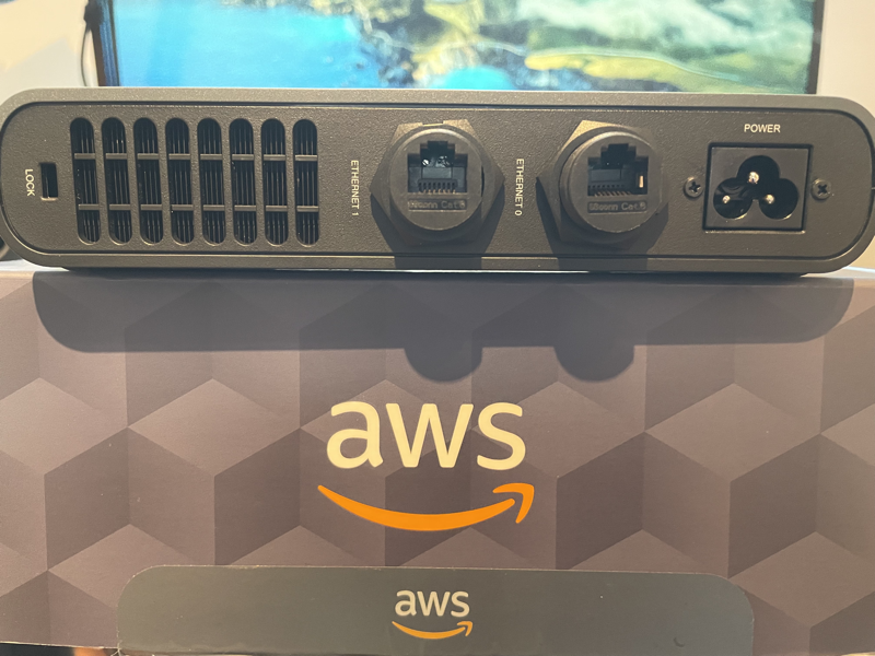
Stop by the Migration & Modernization area of the AWS Village to see hardware innovations inside the latest generation of Outposts up close and personal.
AWS for Industries Pavillion (Booth #111)
Explore how AWS Hybrid and Edge services unlock new use cases and improve operational efficiency across multiple industries through immersive experiences:
- AWS for Telecom – Modernizing telecom infrastructure while meeting data sovereignty and performance requirements
- AWS for Public Sector – Accelerating tactical edge deployments to improve mission outcomes
- AWS for Automotive – Advancing global R&D of embedded hardware and software
Partner booths
Discover how AWS Hybrid and Edge services and AWS Partner solutions unlock additional use cases through demos:
- Pure Storage (Booth #1756) – Simplifying cloud migration with on-premises dependencies through Outposts integration with Pure Storage FlashArray
- Intel (Booth #1010): – Powering physical AI and agentic systems for real-time operations in manufacturing
- Seagate (Booth #159) – Facilitating data ingestion and pre-processing at the edge
Ready for re:Invent 2025?
We hope this guide to hybrid cloud and edge computing helps you maximize your learning experience at re:Invent. Not able to attend in-person? Register for the virtual-only event offered at no additional cost to livestream keynotes and innovation talks, and access on-demand session content. See you in Las Vegas or virtually!