Post Syndicated from Patrick O'Connor original https://aws.amazon.com/blogs/big-data/build-efficient-cross-regional-i-o-intensive-workloads-with-dask-on-aws/
Welcome to the era of data. The sheer volume of data captured daily continues to grow, calling for platforms and solutions to evolve. Services such as Amazon Simple Storage Service (Amazon S3) offer a scalable solution that adapts yet remains cost-effective for growing datasets. The Amazon Sustainability Data Initiative (ASDI) uses the capabilities of Amazon S3 to provide a no-cost solution for you to store and share climate science workloads across the globe. Amazon’s Open Data Sponsorship Program allows organizations to host free of charge on AWS.
Over the last decade, we’ve seen a surge in data science frameworks coming to fruition, along with mass adoption by the data science community. One such framework is Dask, which is powerful for its ability to provision an orchestration of worker compute nodes, thereby accelerating complex analysis on large datasets.
In this post, we show you how to deploy a custom AWS Cloud Development Kit (AWS CDK) solution that extends Dask’s functionality to work inter-Regionally across Amazon’s global network. The AWS CDK solution deploys a network of Dask workers across two AWS Regions, connecting into a client Region. For more information, refer to Guidance for Distributed Computing with Cross Regional Dask on AWS and the GitHub repo for open-source code.
After deployment, the user will have access to a Jupyter notebook, where they can interact with two datasets from ASDI on AWS: Coupled Model Intercomparison Project 6 (CMIP6) and ECMWF ERA5 Reanalysis. CMIP6 focuses on the sixth phase of global coupled ocean-atmosphere general circulation model ensemble; ERA5 is the fifth generation of ECMWF atmospheric reanalyses of the global climate, and the first reanalysis produced as an operational service.
This solution was inspired by work with a key AWS customer, the UK Met Office. The Met Office was founded in 1854 and is the national meteorological service for the UK. They provide weather and climate predictions to help you make better decisions to stay safe and thrive. A collaboration between the Met Office and EUMETSAT, detailed in Data Proximate Computation on a Dask Cluster Distributed Between Data Centres, highlights the growing need to develop a sustainable, efficient, and scalable data science solution. This solution achieves this by bringing compute closer to the data, rather than forcing the data to come closer to compute resources, which adds cost, latency, and energy.
Solution overview
Each day, the UK Met Office produces up to 300 TB of weather and climate data, a portion of which is published to ASDI. These datasets are distributed across the world and hosted for public use. The Met Office would like to enable consumers to make the more of their data to help inform critical decisions on addressing issues such as better preparation for climate change-induced wildfires and floods, and reducing food insecurity through better crop yield analysis.
Traditional solutions in use today, particularly with climate data, are time consuming and unsustainable, replicating datasets cross Regions. Unnecessary data transfer on the petabyte scale is costly, slow, and consumes energy.
We estimated that if this practice were adopted by the Met Office users, the equivalent of 40 homes’ daily power consumption could be saved every day, and they could also reduce the transfer of data between regions.
The following diagram illustrates the solution architecture.

The solution can be broken into three major segments: client, workers, and network. Let’s dive into each and see how they come together.
Client
The client represents the source Region where data scientists connect. This Region (Region A in the diagram) contains an Amazon SageMaker notebook, an Amazon OpenSearch Service domain, and a Dask scheduler as key components. System administrators have access to the built-in Dask dashboard exposed via an Elastic Load Balancer.
Data scientists have access to the Jupyter notebook hosted on SageMaker. The notebook is able to connect and run workloads on the Dask scheduler. The OpenSearch Service domain stores metadata on the datasets connected at the Regions. Notebook users can query this service to retrieve details such as the correct Region of Dask workers without needing to know the data’s Regional location beforehand.
Worker
Each of the worker Regions (Regions B and C in the diagram) is comprised of an Amazon Elastic Container Service (Amazon ECS) cluster of Dask workers, an Amazon FSx for Lustre file system, and a standalone Amazon Elastic Compute Cloud (Amazon EC2) instance. FSx for Lustre allows Dask workers to access and process Amazon S3 data from a high-performance file system by linking your file systems to S3 buckets. It provides sub-millisecond latencies, up to hundreds of GBs/s of throughput, and millions of IOPS. A key feature of Lustre is that only the file system’s metadata is synced. Lustre manages the balance of files to be loaded in and kept warm, based on demand.
Worker clusters scale based on CPU usage, provision additional workers in extended periods of demand, and scale down as resources become idle.
Each night at 0:00 UTC, a data sync job prompts the Lustre file system to resync with the attached S3 bucket, and pulls an up-to-date metadata catalog of the bucket. Subsequently, the standalone EC2 instance pushes these updates into OpenSearch Service respective to that Region’s index. OpenSearch Service provides the necessary information to the client as to which pool of workers should be called upon for a particular dataset.
Network
Networking forms the crux of this solution, utilizing Amazon’s internal backbone network. By using AWS Transit Gateway, we’re able to connect each of the Regions to each other without needing to traverse the public internet. Each of the workers are able to connect dynamically into the Dask scheduler, allowing data scientists to run inter-regional queries through Dask.
Prerequisites
The AWS CDK package uses the TypeScript programming language. Follow the steps in Getting Started for AWS CDK to set up your local environment and bootstrap your development account (you’ll need to bootstrap all Regions specified in the GitHub repo).
For a successful deployment, you’ll need Docker installed and running on your local machine.
Deploy the AWS CDK package
Deploying an AWS CDK package is straightforward. After you install the prerequisites and bootstrap your account, you can proceed with downloading the code base.
- Download the GitHub repository:
# Command to clone the repository
git clone https://github.com/aws-solutions-library-samples/distributed-compute-on-aws-with-cross-regional-dask.git
cd distributed-compute-on-aws-with-cross-regional-dask
- Install node modules:
- Deploy the AWS CDK:
The stack can take over an hour and a half to deploy.
Code walkthrough
In this section, we inspect some of the key features of the code base. If you’d like to inspect the full code base, refer to the GitHub repository.
Configure and customize your stack
In the file bin/variables.ts, you’ll find two variable declarations: one for the client and one for workers. The client declaration is a dictionary with a reference to a Region and CIDR range. Customizing these variables will change both the Region and CIDR range of where client resources will deploy.
The worker variable copies this same functionality; however, it’s a list of dictionaries to accommodate adding or subtracting datasets the user wishes to include. Additionally, each dictionary contains the added fields of dataset and lustreFileSystemPath. Dataset is used to specify the connecting S3 URI for Lustre to connect to. The lustreFileSystemPath variable is used as a mapping for how the user wants that dataset to map locally on the worker file system. See the following code:
export const client: IClient = { region: "eu-west-2", cidr: "10.0.0.0/16" };

export const workers: IWorker[] = [
  {
    region: "us-east-1",
    cidr: "10.1.0.0/16",
    // The public s3 dataset on https://registry.opendata.aws/ you wish to connect to
    dataset: "s3://era5-pds",
    lustreFileSystemPath: "era5-pds",
  },
...]
Dynamically publish the scheduler IP
A challenge inherent to the cross-Regional nature of this project was maintaining a dynamic connection between the Dask workers and the scheduler. How could we publish an IP address, which is capable of changing, across AWS Regions? We were able to accomplish this through the use of AWS Cloud Map and associate-vpc-with-hosted-zone. The service abstracts allowing AWS to manage this DNS namespace privately. See the following code:
    /**
     * Below we initialise a private namespace which will keep track of the changing schedulers IP
     * The workers will need this IP to connect to, so instead of tracking it statically, they can
     * Simply reference the DNS which will resolve to the IP every time
     */
    const PrivateNP = new PrivateDnsNamespace(this, "local-dask", {
      name: "local-dask",
      vpc: this.vpc,
    });
    // Other regions will have to associate-vpc-with-hosted-zone to access this namespace
    new StringParameter(this, "PrivateNP Param", {
      parameterName: `privatenp-hostedid-param-${this.region}`,
      stringValue: PrivateNP.namespaceHostedZoneId,
    });
    this.schedulerDisovery = new Service(this, "Scheduler Discovery", {
      name: "Dask-Scheduler",
      namespace: PrivateNP,
    });
Jupyter notebook UI
The Jupyter notebook hosted on SageMaker provides scientists with a ready-made environment for deployment to easily connect and experiment on the loaded datasets. We used a lifecycle configuration script to provision the notebook with a preconfigured developer environment and example code base. See the following code:
  // The Sagemaker Notebook
  new CfnNotebookInstance(this, "Dask Notebook", {
    notebookInstanceName: "Dask-Notebook",
    rootAccess: "Disabled",
    directInternetAccess: "Disabled",
    defaultCodeRepository: repo.repositoryCloneUrlHttp,
    instanceType: "ml.t3.2xlarge",
    roleArn: role.roleArn,
    subnetId: this.vpc.privateSubnets[0].subnetId,
    securityGroupIds: [SagemakerSec.securityGroupId],
    lifecycleConfigName: lifecycle.notebookInstanceLifecycleConfigName,
    kmsKeyId: nbKey.keyId,
    platformIdentifier: "notebook-al2-v1",
    volumeSizeInGb: 50,
  });
Dask worker nodes
When it comes to the Dask workers, greater customizability is provided, more specifically on instance type, threads per container, and scaling alarms. By default, the workers provision on instance type m5d.4xlarge, mount to the Lustre file system on launch, and subdivide its workers and threads dynamically to ports. All this is optionally customizable. See the following code:
capacity: {
  instanceType: new InstanceType("m5d.4xlarge"),
  minCapacity: 0,
  maxCapacity: 12,
  vpcSubnets: {
    subnetType: SubnetType.PRIVATE_WITH_EGRESS,
  },
},

command: [
  "bin/sh",
  "-c",
  `pip3 install --upgrade xarray[complete] intake_esm s3fs eccodes git+https://github.com/gjoseph92/dask-worker-pools.git@main && dask worker Dask-Scheduler.local-dask:8786 --worker-port 9000:${
    9000 + NWORKERS - 1
  } --nanny-port ${9000 + NWORKERS}:${
    9000 + NWORKERS * 2 - 1
  } --resources pool-${
    this.region
  }=1 --nworkers ${NWORKERS} --nthreads ${THREADS} --no-dashboard`,
],
Performance
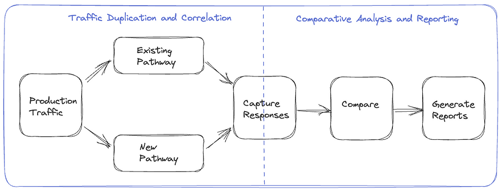
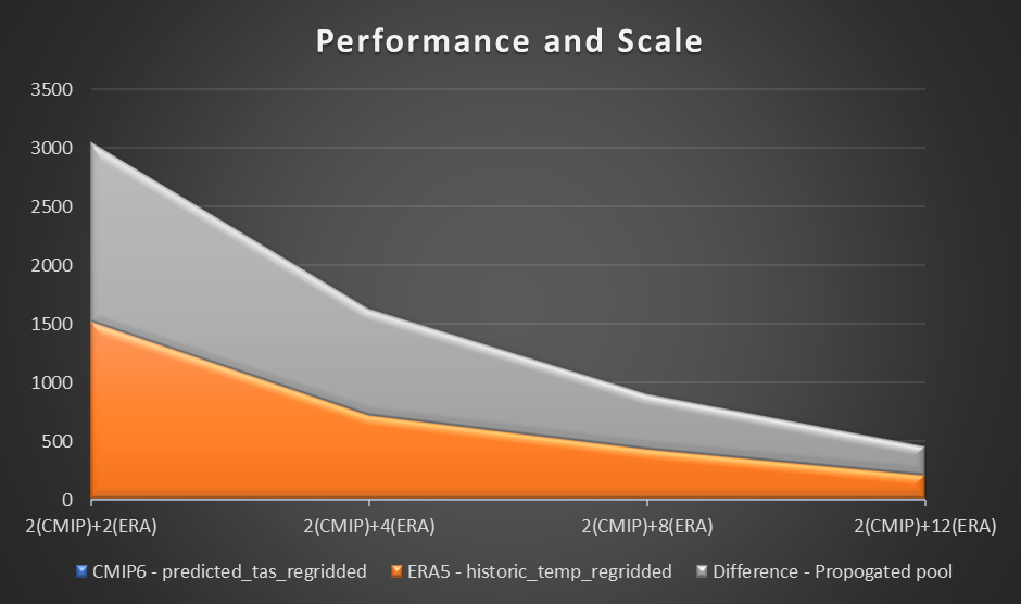
To assess performance, we use a sample computation and plotting of air temperature at 2 meters based on the difference between CMIP6 prediction for a month and ERA5 mean air temperature for 10 years. We set a benchmark of two workers in each Region and assess the difference in time reduction as additional workers were added. In theory, as the solution scales, there should be a productive material difference in reducing overall time.
The following table summarizes our dataset details.
| Dataset |
Variables |
Disk Size |
Xarray Dataset Size |
Region |
| ERA5 |
2011–2020 (120 netcdf files) |
53.5GB |
364.1 GB |
us-east-1 |
| CMIP6 |
variable_ids = ['tas'] # tas is air temperature at 2m above surface
table_id = 'Amon' # Monthly data from Atmosphere
grid = 'gn'
experiment_id = 'ssp245'
activity_ids = ['ScenarioMIP', 'CMIP']
institution_id = 'MOHC'
|
1.13GB |
0.11 GB |
us-west-2 |
The following table shows the results collected, showcasing the time (in seconds) for each computation and prediction in three stages in computing CMIP6 prediction, ERA5, and difference.
| . |
. |
Number of Workers |
| Compute |
Region |
2(CMIP) + 2(ERA) |
2(CMIP) + 4(ERA) |
2(CMIP) + 8(ERA) |
2(CMIP)
+ 12(ERA)
|
CMIP6 (predicted_tas_regridded) |
us-west-2 |
11.8 |
11.5 |
11.2 |
11.6 |
ERA5 (historic_temp_regridded) |
us-east-1 |
1512 |
711 |
427 |
202 |
Difference (propogated pool) |
us-west-2 and us-east-1 |
1527 |
906 |
469 |
251 |
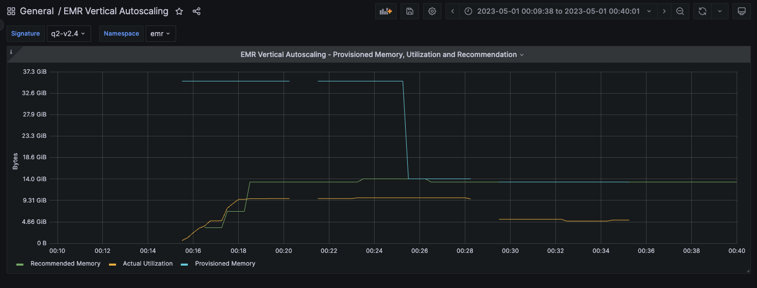
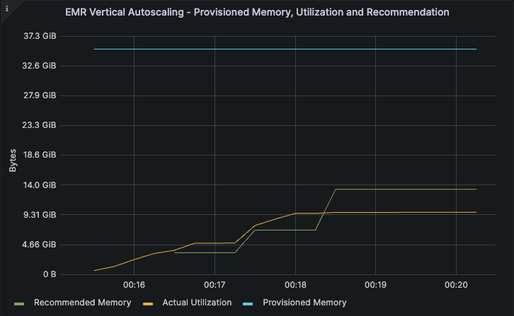
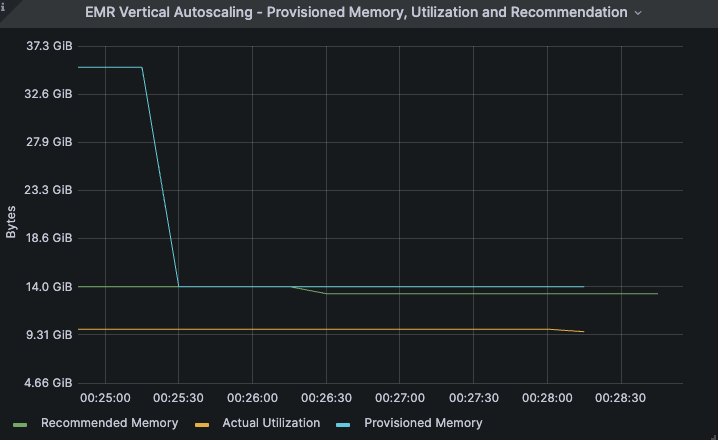
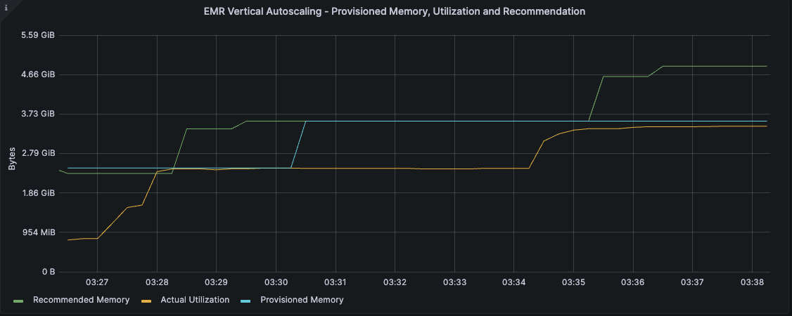
The following graph visualizes the performance and scale.

From our experiment, we observed a linear improvement on computation for the ERA5 dataset as the number of workers increased. As the numbers of workers increased, computation times were at times halved.
Jupyter notebook
As part of the solution launch, we deploy a preconfigured Jupyter notebook to help test the cross-Regional Dask solution. The notebook demonstrates the removed worry of needing to know the Regional location of datasets, instead querying a catalog through a series of Jupyter notebooks running in the background.
To get started, follow the instructions in this section.
The code for the notebooks can be found in lib/SagemakerCode with the primary notebook being ux_notebook.ipynb. This notebook calls upon other notebooks, triggering helper scripts. ux_notebook is designed to be the entry point for scientists, without the need for going elsewhere.
To get started, open this notebook in SageMaker after you have deployed the AWS CDK. The AWS CDK creates a notebook instance with all of the files in the repository loaded and backed up to an AWS CodeCommit repository.
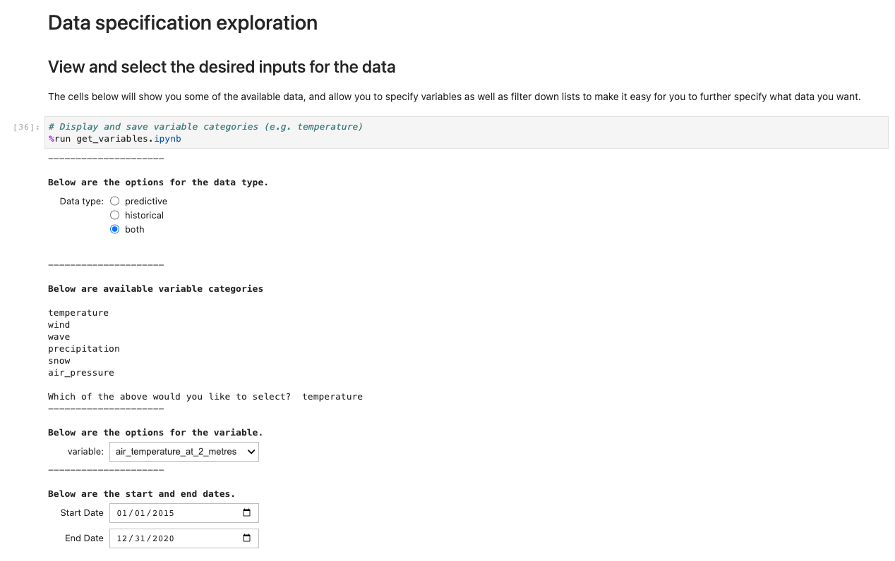
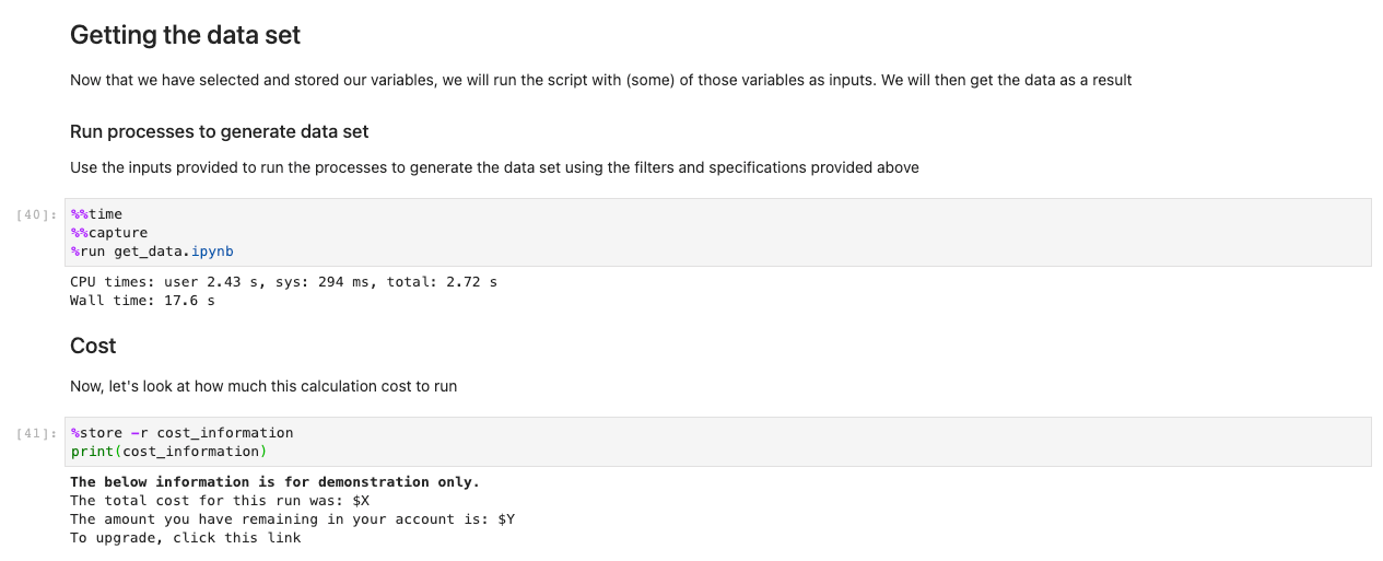
To run the application, open and run the first cell of ux_notebook. This cell runs the get_variables notebook in the background, which prompts you for an input for the data you would like to select. We include an example; however, note that questions will only appear after the previous option has been selected. This is intentional in limiting the drop-down choices and is optionally configurable by editing the get_variables notebook.

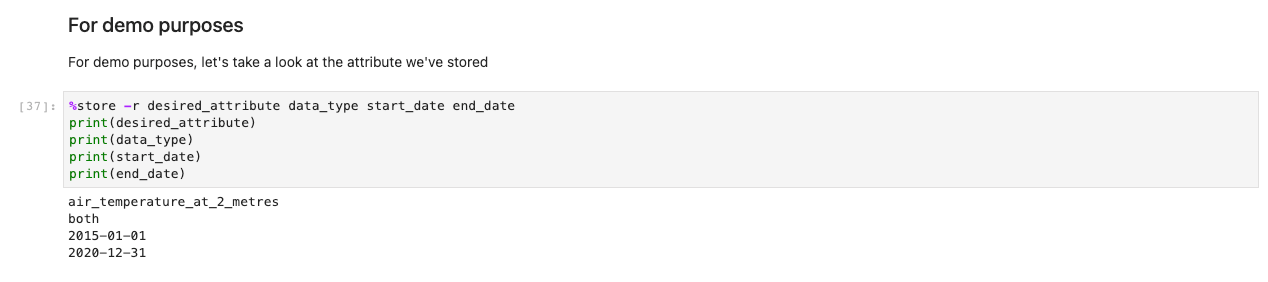
The preceding code stores variables globally so that other notebooks can retrieve and load your selection of choices. For demonstration, the next cell should output the save variables from before.

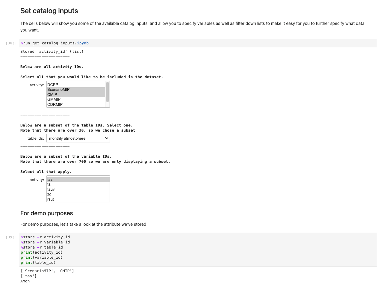
Next, a prompt for further data specifications appears. This cell refines the data you’re after by presenting the IDs of tables in human-readable format. Users select as if it were a form, but the titles map to tables in the background that help the system retrieve the appropriate datasets.

After you have stored all your choices and selection cells, load the data into the Regions by running the cell in the Getting the data set section. The %%capture command will suppress unnecessary outputs from the get_data notebook. Note you may remove this to inspect outputs from the other notebooks. Data is then retrieved in the backend.
While other notebooks are being run in the background, the only touchpoint for the user is the ux_notebook. This is to abstract the tedious process of importing data into a format any user is able to follow with ease.

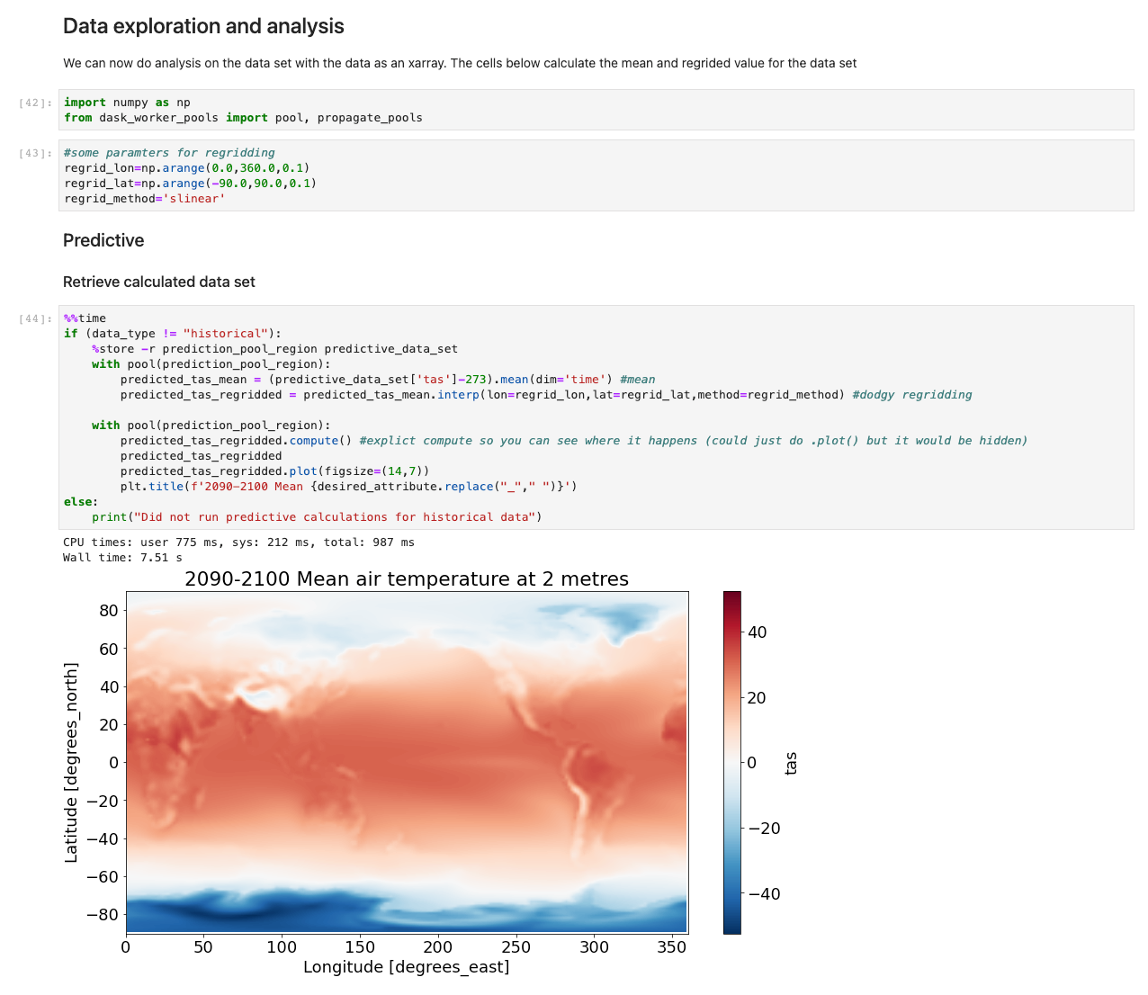
With the data now loaded, we can start interacting with it. The following cells are examples of calculations you may run on weather data. Using xarrays, we import, calculate, and then plot those datasets.
Our sample illustrates a plot of predictive data retrieving data, running the computation, and plotting the results in under 7.5 seconds—orders of magnitude faster than a typical approach.

Under the hood
The notebooks get_catalog_input and get_variables use the library ipywidgets to display widgets such as drop-downs and multi-box selections. These options are saved globally using the %%store command so that they can be accessed from the ux_notebook. One of the options prompts you on whether you want historical data, predictive data, or both. This variable is passed to the get_data notebook to determine which subsequent notebooks to run.
The get_data notebook first retrieves the shared OpenSearch Service domain saved to AWS Systems Manager Parameter Store. This domain allows our notebook to run a query on collecting information that will indicate where the selected datasets are stored Regionally. With those datasets located Regionally, the notebook will make a connection attempt to the Dask scheduler, passing the information collected from OpenSearch Service. The Dask scheduler in turn will be able to call on workers in the correct Regions.
How to customize and continue development
These notebooks are meant to be an example of how you can create a way for users to interface and interact with the data. The notebook in this post serves as an illustration for what’s possible, and we invite you to continue building upon the solution to further improve user engagement. The core part of this solution is the backend technology, but without some mechanism to interact with that backend, users won’t realize the full potential of the solution.
Clean up
To avoid incurring future charges, delete the resources. Let’s destroy our deployed solution with the following command:
Conclusion
This post showcases the extension of Dask inter-Regionally on AWS, and a possible integration with public datasets on AWS. The solution was built as a generic pattern, and further datasets can be loaded in to accelerate high I/O analyses on complex data.
Data is transforming every field and every business. However, with data growing faster than most companies can keep track of, collecting data and getting value out of that data is challenging. A modern data strategy can help you create better business outcomes with data. AWS provides the most complete set of services for the end-to-end data journey to help you unlock value from your data and turn it into insight.
To learn more about the various ways to use your data on the cloud, visit the AWS Big Data Blog. We further invite you to comment with your thoughts on this post, and whether this is a solution you plan on trying out.
About the Authors
 Patrick O’Connor is a WWSO Prototyping Engineer based in London. He is a creative problem-solver, adaptable across a wide range of technologies, such as IoT, serverless tech, 3D spatial tech, and ML/AI, along with a relentless curiosity on how technology can continue to evolve everyday approaches.
 Chakra Nagarajan is a Principal Machine Learning Prototyping SA with 21 years of experience in machine learning, big data, and high-performance computing. In his current role, he helps customers solve real-world complex business problems by building prototypes with end-to-end AI/ML solutions in cloud and edge devices. His ML specialization includes computer vision, natural language processing, time series forecasting, and personalization.
Val Cohen is a senior WWSO Prototyping Engineer based in London. A problem solver by nature, Val enjoys writing code to automate processes, build customer obsessed tools, and create infrastructure for various applications for her global customer base. Val has experience across a wide variety of technologies, such as front-end web development, backend work, and AI/ML.
Niall Robinson is Head of product futures at the UK Met Office. He and his team explore new ways the Met Office can provide value through product innovation and strategic partnerships. He’s had a varied career, leading a multidisciplinary informatics R&D team, academic research in data science, and field scientist along with climate modeler expertise.


 (@yavorsky_)


![[Below] On this site on May 12th, 2023, I finally learned how to use the masonry bit for my drill.](https://imgs.xkcd.com/comics/commemorative_plaque.png "[Below] On this site on May 12th, 2023, I finally learned how to use the masonry bit for my drill.")


 Hari Thatavarthy is a Senior Solutions Architect on the AWS Data Lab team. He helps customers design and build solutions in the data and analytics space. He believes in data democratization and loves to solve complex data processing-related problems. In his spare time, he loves to play table tennis.
 Krishna Maddileti is a Senior Solutions Architect on the AWS Data Lab team. He partners with customers on their AWS journey and helps them with data engineering, data lakes, and analytics. In his spare time, he enjoys spending time with his family and playing video games with his 7-year-old.
 Yadukishore Tatavarthi is a Senior Partner Solutions Architect at AWS. He works closely with global system integrator partners to enable and support customers moving their workloads to AWS.
 Manish Kola is a Solutions Architect on the AWS Data Lab team. He partners with customers on their AWS journey.
 Noritaka Sekiyama is a Principal Big Data Architect on the AWS Glue team. He is responsible for building software artifacts to help customers. In his spare time, he enjoys cycling with his new road bike.