Post Syndicated from Donnie Prakoso original https://aws.amazon.com/blogs/aws/aws-fargate-enables-faster-container-startup-using-seekable-oci/
While developing with containers is becoming an increasingly popular way for deploying and scaling applications, there are still areas where improvements can be made. One of the main issues with scaling containerized applications is the long startup time, especially during scale up when newer instances need to be added. This issue can have a negative impact on the customer experience, for example when a website needs to scale out to serve additional traffic.
A research paper shows that container image downloads account for 76 percent of container startup time, but on average only 6.4 percent of the data is needed for the container to start doing useful work. Starting and scaling out containerized applications requires downloading container images from a remote container registry. This may introduce a non-trivial latency, as the entire image must be downloaded and unpacked before the applications can be started.
One solution to this problem is lazy loading (also known as asynchronous loading) container images. This approach downloads data from the container registry in parallel with the application startup, such as stargz-snapshotter, a project that aims to improve the overall container start time.
Last year, we introduced Seekable OCI (SOCI), a technology open sourced by Amazon Web Services (AWS) that enables container runtimes to implement lazy loading the container image to start applications faster without modifying the container images. As part of that effort, we open sourced SOCI Snapshotter, a snapshotter plugin that enables lazy loading with SOCI in containerd.
AWS Fargate Support for SOCI
Today, I’m excited to share that AWS Fargate now supports Seekable OCI (SOCI), which helps applications deploy and scale out faster by enabling containers to start without waiting to download the entire container image. At launch, this new capability is available for Amazon Elastic Container Service (Amazon ECS) applications running on AWS Fargate.
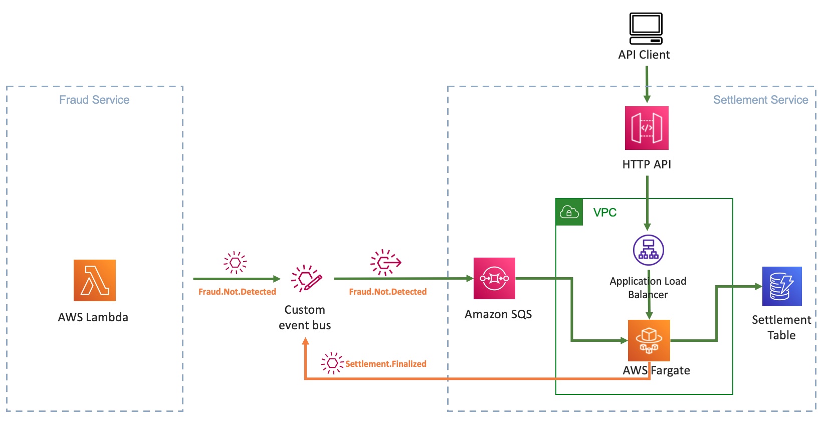
Here’s a quick look to show how AWS Fargate support for SOCI works:

SOCI works by creating an index (SOCI index) of the files within an existing container image. This index is a key enabler to launching containers faster, providing the capability to extract an individual file from a container image without having to download the entire image. Your applications no longer need to wait to complete pulling and unpacking a container image before your applications start running. This allows you to deploy and scale out applications more quickly and reduce the rollout time for application updates.
A SOCI index is generated and stored separately from the container images. This means that your container images don’t need to be converted to use SOCI, therefore not breaking secure hash algorithm (SHA)-based security, such as container image signing. The index is then stored in the registry alongside the container image. At release, AWS Fargate support for SOCI works with Amazon Elastic Container Registry (Amazon ECR).
When you use Amazon ECS with AWS Fargate to run your SOCI-indexed containerized images, AWS Fargate automatically detects if a SOCI index for the image exists and starts the container without waiting for the entire image to be pulled. This also means that AWS Fargate will still continue to run container images that don’t have SOCI indexes.
Let’s Get Started
There are two ways to create SOCI indexes for container images.
- Use AWS SOCI Index Builder – AWS SOCI Index Builder is a serverless solution for indexing container images in the AWS Cloud. This AWS CloudFormation stack deploys an Amazon EventBridge rule to identify Amazon ECR action events and invoke an AWS Lambda function to match the defined filter. Then, another AWS Lambda function generates and pushes SOCI indexes to repositories in the Amazon ECR registry.
- Create SOCI indexes manually – This approach provides more flexibility on in how the SOCI indexes are created, including for existing container images in Amazon ECR repositories. To create SOCI indexes, you can use the
sociCLI provided by the soci-snapshotter project.
The AWS SOCI Index Builder provides you with an automated process to get started and build SOCI indexes for your container images. The sociCLI provides you with more flexibility around index generation and the ability to natively integrate index generation in your CI/CD pipelines.
In this article, I manually generate SOCI indexes using the soci CLI from the soci-snapshotter project.
Create a Repository and Push Container Images
First, I create an Amazon ECR repository called pytorch-socifor my container image using AWS CLI.
$ aws ecr create-repository --region us-east-1 --repository-name pytorch-sociI keep the Amazon ECR URI output and define it as a variable to make it easier for me to refer to the repository in the next step.
$ ECRSOCIURI=xyz.dkr.ecr.us-east-1.amazonaws.com/pytorch-soci:latestFor the sample application, I use a PyTorch training (CPU-based) container image from AWS Deep Learning Containers. I use the nerdctl CLI to pull the container image because, by default, the Docker Engine stores the container image in the Docker Engine image store, not the containerd image store.
$ SAMPLE_IMAGE="763104351884.dkr.ecr.us-east-1.amazonaws.com/pytorch-training:1.5.1-cpu-py36-ubuntu16.04"
$ aws ecr get-login-password --region us-east-1 | sudo nerdctl login --username AWS --password-stdin xyz.dkr.ecr.ap-southeast-1.amazonaws.com
$ sudo nerdctl pull --platform linux/amd64 $SAMPLE_IMAGE
Then, I tag the container image for the repository that I created in the previous step.
$ sudo nerdctl tag $SAMPLE_IMAGE $ECRSOCIURINext, I need to push the container image into the ECR repository.
$ sudo nerdctl push $ECRSOCIURIAt this point, my container image is already in my Amazon ECR repository.

Create SOCI Indexes
Next, I need to create SOCI index.
A SOCI index is an artifact that enables lazy loading of container images. A SOCI index consists of 1) a SOCI index manifest and 2) a set of zTOCs. The following image illustrates the components in a SOCI index manifest, and how it refers to a container image manifest.
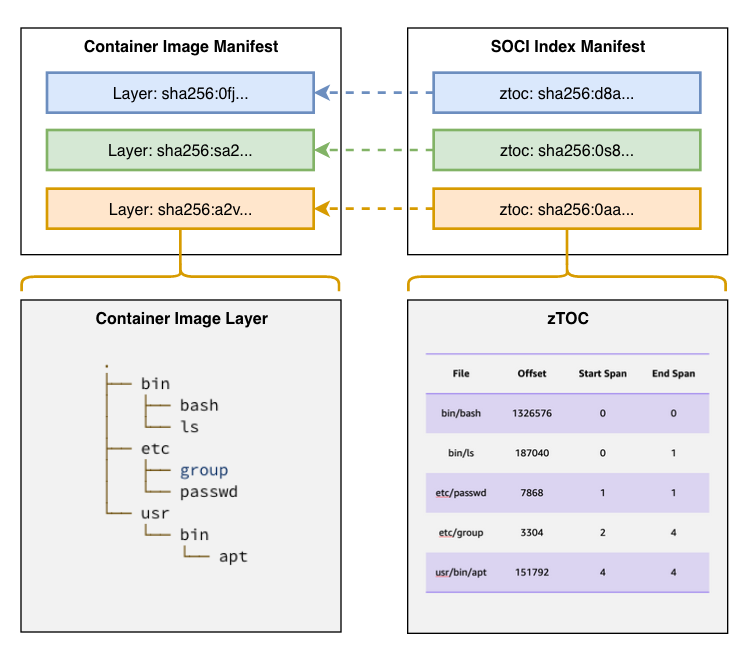
The SOCI index manifest contains the list of zTOCs and a reference to the image for which the manifest was generated. A zTOC, or table of contents for compressed data, consists of two parts:
- TOC, a table of contents containing file metadata and the corresponding offset in the decompressed TAR archive.
- zInfo, a collection of checkpoints representing the state of the compression engine at various points in the layer.
To learn more about the concept and term, please visit soci-snapshotter Terminology page.
Before I can create SOCI indexes, I need to install the sociCLI. To learn more about how to install the soci, visit Getting Started with soci-snapshotter.
To create SOCI indexes, I use the soci create command.
$ sudo soci create $ECRSOCIURI
layer sha256:4c6ec688ebe374ea7d89ce967576d221a177ebd2c02ca9f053197f954102e30b -> ztoc skipped
layer sha256:ab09082b308205f9bf973c4b887132374f34ec64b923deef7e2f7ea1a34c1dad -> ztoc skipped
layer sha256:cd413555f0d1643e96fe0d4da7f5ed5e8dc9c6004b0731a0a810acab381d8c61 -> ztoc skipped
layer sha256:eee85b8a173b8fde0e319d42ae4adb7990ed2a0ce97ca5563cf85f529879a301 -> ztoc skipped
layer sha256:3a1b659108d7aaa52a58355c7f5704fcd6ab1b348ec9b61da925f3c3affa7efc -> ztoc skipped
layer sha256:d8f520dcac6d926130409c7b3a8f77aea639642ba1347359aaf81a8b43ce1f99 -> ztoc skipped
layer sha256:d75d26599d366ecd2aa1bfa72926948ce821815f89604b6a0a49cfca100570a0 -> ztoc skipped
layer sha256:a429d26ed72a85a6588f4b2af0049ae75761dac1bb8ba8017b8830878fb51124 -> ztoc skipped
layer sha256:5bebf55933a382e053394e285accaecb1dec9e215a5c7da0b9962a2d09a579bc -> ztoc skipped
layer sha256:5dfa26c6b9c9d1ccbcb1eaa65befa376805d9324174ac580ca76fdedc3575f54 -> ztoc skipped
layer sha256:0ba7bf18aa406cb7dc372ac732de222b04d1c824ff1705d8900831c3d1361ff5 -> ztoc skipped
layer sha256:4007a89234b4f56c03e6831dc220550d2e5fba935d9f5f5bcea64857ac4f4888 -> ztoc sha256:0b4d78c856b7e9e3d507ac6ba64e2e2468997639608ef43c088637f379bb47e4
layer sha256:089632f60d8cfe243c5bc355a77401c9a8d2f415d730f00f6f91d44bb96c251b -> ztoc sha256:f6a16d3d07326fe3bddbdb1aab5fbd4e924ec357b4292a6933158cc7cc33605b
layer sha256:f18dd99041c3095ade3d5013a61a00eeab8b878ba9be8545c2eabfbca3f3a7f3 -> ztoc sha256:95d7966c964dabb54cb110a1a8373d7b88cfc479336d473f6ba0f275afa629dd
layer sha256:69e1edcfbd217582677d4636de8be2a25a24775469d677664c8714ed64f557c3 -> ztoc sha256:ac0e18bd39d398917942c4b87ac75b90240df1e5cb13999869158877b400b865
From the above output, I can see that sociCLI created zTOCs for four layers, which and this means only these four layers will be lazily pulled and the other container image layers will be downloaded in full before the container image starts. This is because there is less of a launch time impact in lazy loading very small container image layers. However, you can configure this behavior using the --min-layer-size flag when you run soci create.
Verify and Push SOCI Indexes
The soci CLI also provides several commands that can help you to review the SOCI Indexes that have been generated.
To see a list of all index manifests, I can run the following command.
$ sudo soci index list

DIGEST                                                                     SIZE    IMAGE REF                                                                                   PLATFORM       MEDIA TYPE                                    CREATED
sha256:ea5c3489622d4e97d4ad5e300c8482c3d30b2be44a12c68779776014b15c5822    1931    xyz.dkr.ecr.us-east-1.amazonaws.com/pytorch-soci:latest                                     linux/amd64    application/vnd.oci.image.manifest.v1+json    10m4s ago
sha256:ea5c3489622d4e97d4ad5e300c8482c3d30b2be44a12c68779776014b15c5822    1931    763104351884.dkr.ecr.us-east-1.amazonaws.com/pytorch-training:1.5.1-cpu-py36-ubuntu16.04    linux/amd64    application/vnd.oci.image.manifest.v1+json    10m4s ago
While optional, if I need to see the list of zTOC, I can use the following command.
$ sudo soci ztoc list
DIGEST                                                                     SIZE        LAYER DIGEST
sha256:0b4d78c856b7e9e3d507ac6ba64e2e2468997639608ef43c088637f379bb47e4    2038072     sha256:4007a89234b4f56c03e6831dc220550d2e5fba935d9f5f5bcea64857ac4f4888
sha256:95d7966c964dabb54cb110a1a8373d7b88cfc479336d473f6ba0f275afa629dd    11442416    sha256:f18dd99041c3095ade3d5013a61a00eeab8b878ba9be8545c2eabfbca3f3a7f3
sha256:ac0e18bd39d398917942c4b87ac75b90240df1e5cb13999869158877b400b865    36277264    sha256:69e1edcfbd217582677d4636de8be2a25a24775469d677664c8714ed64f557c3
sha256:f6a16d3d07326fe3bddbdb1aab5fbd4e924ec357b4292a6933158cc7cc33605b    10152696    sha256:089632f60d8cfe243c5bc355a77401c9a8d2f415d730f00f6f91d44bb96c251b
This series of zTOCs contains all of the information that SOCI needs to find a given file in a layer. To review the zTOC for each layer, I can use one of the digest sums from the preceding output and use the following command.
$ sudo soci ztoc info sha256:0b4d78c856b7e9e3d507ac6ba64e2e2468997639608ef43c088637f379bb47e4
{
  "version": "0.9",
  "build_tool": "AWS SOCI CLI v0.1",
  "size": 2038072,
  "span_size": 4194304,
  "num_spans": 33,
  "num_files": 5552,
  "num_multi_span_files": 26,
  "files": [
    {
      "filename": "bin/",
      "offset": 512,
      "size": 0,
      "type": "dir",
      "start_span": 0,
      "end_span": 0
    },
    {
      "filename": "bin/bash",
      "offset": 1024,
      "size": 1037528,
      "type": "reg",
      "start_span": 0,
      "end_span": 0
    }

---Trimmed for brevity---
Now, I need to use the following command to push all SOCI-related artifacts into the Amazon ECR.
$ PASSWORD=$(aws ecr get-login-password --region us-east-1)
$ sudo soci push --user AWS:$PASSWORD $ECRSOCIURI
If I go to my Amazon ECR repository, I can verify the index is created. Here, I can see that two additional objects are listed alongside my container image: a SOCI Index and an Image index. The image index allows AWS Fargate to look up SOCI indexes associated with my container image.

Understanding SOCI Performance
The main objective of SOCI is to minimize the required time to start containerized applications. To measure the performance of AWS Fargate lazy loading container images using SOCI, I need to understand how long it takes for my container images to start with SOCI and without SOCI.
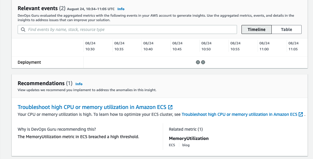
To understand the duration needed for each container image to start, I can use metrics available from the DescribeTasks API on Amazon ECS. The first metric is createdAt, the timestamp for the time when the task was created and entered the PENDING state. The second metric is startedAt, the time when the task transitioned from the PENDING state to the RUNNING state.
For this, I have created another Amazon ECR repository using the same container image but without generating a SOCI index, called pytorch-without-soci. If I compare these container images, I have two additional objects in pytorch-soci(an image index and a SOCI index) that don’t exist in pytorch-without-soci.

Deploy and Run Applications
To run the applications, I have created an Amazon ECS cluster called demo-pytorch-soci-cluster, a VPC and the required ECS task execution role. If you’re new to Amazon ECS, you can follow Getting started with Amazon ECS to be more familiar with how to deploy and run your containerized applications.
Now, let’s deploy and run both the container images with FARGATE as the launch type. I define five tasks for each pytorch-sociand pytorch-without-soci.
$ aws ecs \
    --region us-east-1 \
    run-task \
    --count 5 \
    --launch-type FARGATE \
    --task-definition arn:aws:ecs:us-east-1:XYZ:task-definition/pytorch-soci \
    --cluster socidemo

$ aws ecs \
    --region us-east-1 \
    run-task \
    --count 5 \
    --launch-type FARGATE \
    --task-definition arn:aws:ecs:us-east-1:XYZ:task-definition/pytorch-without-soci \
    --cluster socidemo
After a few minutes, there are 10 running tasks on my ECS cluster.

After verifying that all my tasks are running, I run the following script to get two metrics: createdAt and startedAt.
#!/bin/bash
CLUSTER=<CLUSTER_NAME>
TASKDEF=<TASK_DEFINITION>
REGION="us-east-1"
TASKS=$(aws ecs list-tasks \
    --cluster $CLUSTER \
    --family $TASKDEF \
    --region $REGION \
    --query 'taskArns[*]' \
    --output text)

aws ecs describe-tasks \
    --tasks $TASKS \
    --region $REGION \
    --cluster $CLUSTER \
    --query "tasks[] | reverse(sort_by(@, &createdAt)) | [].[{startedAt: startedAt, createdAt: createdAt, taskArn: taskArn}]" \
    --output table
Running the above command for the container image without SOCI indexes — pytorch-without-soci— produces following output:
-------------------------------------------------------------------------------------------------------------------------------------------------------------------------------------
|                                                                                   DescribeTasks                                                                                   |
+----------------------------------+-----------------------------------+------------------------------------------------------------------------------------------------------------+
|             createdAt            |             startedAt             |                                                  taskArn                                                   |
+----------------------------------+-----------------------------------+------------------------------------------------------------------------------------------------------------+
|  2023-07-07T17:43:59.233000+00:00|  2023-07-07T17:46:09.856000+00:00 |  arn:aws:ecs:ap-southeast-1:xyz:task/demo-pytorch-soci-cluster/dcdf19b6e66444aeb3bc607a3114fae0   |
|  2023-07-07T17:43:59.233000+00:00|  2023-07-07T17:46:09.459000+00:00 |  arn:aws:ecs:ap-southeast-1:xyz:task/demo-pytorch-soci-cluster/9178b75c98ee4c4e8d9c681ddb26f2ca   |
|  2023-07-07T17:43:59.233000+00:00|  2023-07-07T17:46:21.645000+00:00 |  arn:aws:ecs:ap-southeast-1:xyz:task/demo-pytorch-soci-cluster/7da51e036c414cbab7690409ce08cc99   |
|  2023-07-07T17:43:59.233000+00:00|  2023-07-07T17:46:00.606000+00:00 |  arn:aws:ecs:ap-southeast-1:xyz:task/demo-pytorch-soci-cluster/5ee8f48194874e6dbba75a5ef753cad2   |
|  2023-07-07T17:43:59.233000+00:00|  2023-07-07T17:46:02.461000+00:00 |  arn:aws:ecs:ap-southeast-1:xyz:task/demo-pytorch-soci-cluster/58531a9e94ed44deb5377fa997caec36   |
+----------------------------------+-----------------------------------+------------------------------------------------------------------------------------------------------------+
From the average aggregated delta time (between startedAt and createdAt) for each task, the pytorch-without-soci (without SOCI indexes) successfully ran after 129 seconds.
Next, I’m running same command but for pytorch-sociwhich comes with SOCI indexes.
-------------------------------------------------------------------------------------------------------------------------------------------------------------------------------------
|                                                                                   DescribeTasks                                                                                   |
+----------------------------------+-----------------------------------+------------------------------------------------------------------------------------------------------------+
|             createdAt            |             startedAt             |                                                  taskArn                                                   |
+----------------------------------+-----------------------------------+------------------------------------------------------------------------------------------------------------+
|  2023-07-07T17:43:53.318000+00:00|  2023-07-07T17:44:51.076000+00:00 |  arn:aws:ecs:ap-southeast-1:xyz:task/demo-pytorch-soci-cluster/c57d8cff6033494b97f6fd0e1b797b8f   |
|  2023-07-07T17:43:53.318000+00:00|  2023-07-07T17:44:52.212000+00:00 |  arn:aws:ecs:ap-southeast-1:xyz:task/demo-pytorch-soci-cluster/6d168f9e99324a59bd6e28de36289456   |
|  2023-07-07T17:43:53.318000+00:00|  2023-07-07T17:45:05.443000+00:00 |  arn:aws:ecs:ap-southeast-1:xyz:task/demo-pytorch-soci-cluster/4bdc43b4c1f84f8d9d40dbd1a41645da   |
|  2023-07-07T17:43:53.318000+00:00|  2023-07-07T17:44:50.618000+00:00 |  arn:aws:ecs:ap-southeast-1:xyz:task/demo-pytorch-soci-cluster/43ea53ea84154d5aa90f8fdd7414c6df   |
|  2023-07-07T17:43:53.318000+00:00|  2023-07-07T17:44:50.777000+00:00 |  arn:aws:ecs:ap-southeast-1:xyz:task/demo-pytorch-soci-cluster/0731bea30d42449e9006a5d8902756d5   |
+----------------------------------+-----------------------------------+------------------------------------------------------------------------------------------------------------+
Here, I see my container image with SOCI-enabled — pytorch-soci — was started 60 seconds after being created.
This means that running my sample application with SOCI indexes on AWS Fargate is approximately 50 percent faster compared to running without SOCI indexes.
It’s recommended to benchmark the startup and scaling-out time of your application with and without SOCI. This helps you to have a better understanding of how your application behaves and if your applications benefit from AWS Fargate support for SOCI.
Customer Voices
During the private preview period, we heard lots of feedback from our customers about AWS Fargate support for SOCI. Here’s what our customers say:
![]()
Autodesk provides critical design, make, and operate software solutions across the architecture, engineering, construction, manufacturing, media, and entertainment industries. “SOCI has given us a 50% improvement in startup performance for our time-sensitive simulation workloads running on Amazon ECS with AWS Fargate. This allows our application to scale out faster, enabling us to quickly serve increased user demand and save on costs by reducing idle compute capacity. The AWS Partner Solution for creating the SOCI index is easy to configure and deploy.” – Boaz Brudner, Head of Innovyze SaaS Engineering, AI and Architecture, Autodesk.
![]()
Flywire is a global payments enablement and software company, on a mission to deliver the world’s most important and complex payments. “We run multi-step deployment pipelines on Amazon ECS with AWS Fargate which can take several minutes to complete. With SOCI, the total pipeline duration is reduced by over 50% without making any changes to our applications, or the deployment process. This allowed us to drastically reduce the rollout time for our application updates. For some of our larger images of over 750MB, SOCI improved the task startup time by more than 60%.”, Samuel Burgos, Sr. Cloud Security Engineer, Flywire.

Virtuoso is a leading software corporation that makes functional UI and end-to-end testing software. “SOCI has helped us reduce the lag between demand and availability of compute. We have very bursty workloads which our customers expect to start as fast as possible. SOCI helps our ECS tasks spin-up 40% faster, allowing us to quickly scale our application and reduce the pool of idle compute capacity, enabling us to deliver value more efficiently. Setting up SOCI was really easy. We opted to use the quick-start AWS Partner’s solution with which we could leave our build and deployment pipelines untouched.”, Mathew Hall, Head of Site Reliability Engineering, Virtuoso.
Things to Know
Availability — AWS Fargate support for SOCI is available in all AWS Regions where Amazon ECS, AWS Fargate, and Amazon ECR are available.
Pricing — AWS Fargate support for SOCI is available at no additional cost and you will only be charged for storing the SOCI indexes in Amazon ECR.
Get Started — Learn more about benefits and how to get started on the AWS Fargate Support for SOCI page.
Happy building.
— Donnie


 Hari Ohm Prasath is a Senior Modernization Architect at AWS, helping customers with their modernization journey to become cloud native. Hari loves to code and actively contributes to the open source initiatives. You can find him in Medium, Github & Twitter @hariohmprasath.
 Ballu Singh is a Principal Solutions Architect at AWS. He lives in the San Francisco Bay area and helps customers architect and optimize applications on AWS. In his spare time, he enjoys reading and spending time with his family.


![Architecture Diagram showing the service “Test” using the container “brickwall-maker” with a desired count of two. The two ECS Task’s vended metrics are then processed by CloudWatch Container Insights. Both, CloudWatch Container Insights and CloudTrail, are ingested by Amazon DevOps Guru which then makes detected insights available to the user. [Image: DevOpsGuruBlog1.png]V1: DevOpsGuruBlog1.drawio (https://api.quip-amazon.com/2/blob/fbe9AAT37Ge/LdkTqbmlZ8uNj7A44pZbnw?name=DevOpsGuruBlog1.drawio&s=cVbmAWsXnynz) V2: DevOpsGuruBlog1.drawio (https://api.quip-amazon.com/2/blob/fbe9AAT37Ge/SvsNTJLEJOHHBls_kV7EwA?name=DevOpsGuruBlog1.drawio&s=cVbmAWsXnynz) V3: DevOpsGuruBlog1.drawio (https://api.quip-amazon.com/2/blob/fbe9AAT37Ge/DqKTxtQvmOLrzM3KcF_oTg?name=DevOpsGuruBlog1.drawio&s=cVbmAWsXnynz)](https://d2908q01vomqb2.cloudfront.net/7719a1c782a1ba91c031a682a0a2f8658209adbf/2021/10/29/DevOpsGuruBlog1-1-1.png)