Tag Archives: Amazon Elastic Container Service

An elastic deployment of Stable Diffusion with Discord on AWS

Post Syndicated from Steven Warren original https://aws.amazon.com/blogs/architecture/an-elastic-deployment-of-stable-diffusion-with-discord-on-aws/

Stable Diffusion is a state-of-the-art text-to-image model that generates images from text. Deploying text-to-image models such as Stable Diffusion can be difficult. Currently, Stable Diffusion requires specific computer hardware known as graphical processing units (GPUs). You can lower the bar to entry by offloading the text-to-image generation onto Amazon Web Services (AWS).

Discord is a popular voice, video, and text communication service. It provides a user interface that people can use to make text-to-image requests. When deployed, all members of a Discord server can create images by using Discord Slash Commands.

In this post, we discuss how to deploy a highly available solution on AWS. This solution will perform text-to-image generation with Stable Diffusion and use Discord as the user interface.

Solution architecture

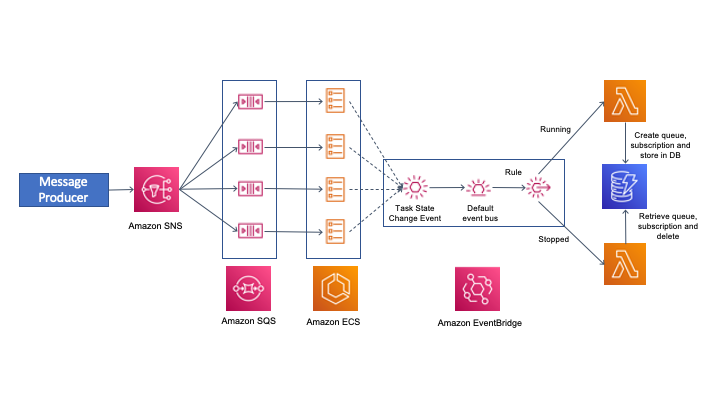
Many of the services selected are serverless, which will offer many benefits. At the time of writing, Stable Diffusion requires a GPU for inference. Amazon Elastic Compute Cloud (Amazon EC2) was selected because it provides GPUs. The solution architecture is shown in the Figure 1.

Solution architecture diagram

Figure 1. Solution architecture diagram

Let us walk through the architecture of this solution.

Auto scaling with custom metrics

To properly scale the system, a custom Amazon CloudWatch metric is created. This custom CloudWatch metric calculates the number of Amazon Elastic Container Service (Amazon ECS) tasks required to adequately handle the amount of Amazon Simple Queue Service (Amazon SQS) messages. You should have a high-resolution CloudWatch metric to scale up quickly. For this use case, a high-resolution CloudWatch metric of every 10 seconds was implemented.

Next, let’s create the custom CW metric. Amazon EventBridge rules provide a serverless solution for starting actions on a schedule. Here we use an Amazon EventBridge rule, which initiates an AWS Step Function Express Workflow every minute. With the Express Workflow, we can create serverless workflows that take less than five minutes, which helps us avoid long running AWS Lambda functions. The Express Workflow runs a Lambda function every 10 seconds over a one-minute period, which generates the custom CloudWatch metric.

Two high-resolution CloudWatch alarms scale the system up and down, and are initiated by the custom CloudWatch metric. One CloudWatch alarm increases the ECS tasks and EC2 machines. The other alarm decreases the ECS tasks and EC2 machines.

Handling Discord requests

Someone on Discord sends a request. The Amazon API Gateway HTTP API receives the request and passes the information to an AWS Lambda function. The HTTP API provides a cost-effective option compared to REST APIs and provides tools for authentication and authorization. The HTTP API uses cross-origin resource sharing (CORS), which provides security because it only allows discord.com as an origin.

The AWS Lambda function provides a serverless solution for responding to the HTTP API requests. It transforms the HTTP API request and sends a message to the SQS First-In-First-Out (FIFO) queue. SQS seamelessly decouples the architecture between user requests and backend processing. A FIFO queue ensures that user requests are processed in the order they were requested. The AWS Lambda function sends a response back to the HTTP API within three seconds, which is a requirement of Discord Slash Commands.

When scaling up, an EC2 instance is registered with the ECS cluster. The EC2 instance type was selected because it provides GPU instances. ECS provides a repeatable solution to deploy the container across a variety of instance types. This solution currently only uses the g4dn.xlarge instance type. The ECS service will then place an ECS task onto the eligible EC2 instance. The ECS task will use the Amazon Elastic Container Registry (Amazon ECR) private registry to pull the image,  perform text-to-image processing, and respond to the Discord request. The ECR private registry is a managed container registry that manages the image.

Once there is an ECS task running on an Amazon EC2 instance, the ECS task will consume messages from the queue using long polling. This reduces the amount of ReceiveMessage requests the ECS task needs to send. When the ECS task receives a message from the queue, it will then processes the request.

Estimated monthly cost

The example assumes 1,000 requests per month and each request takes 16 seconds to complete. Extra EC2 time was added for the time to begin processing messages (seven minutes) and auto scaling cooldown time (30 minutes). You can adjust the pricing calculations with the AWS Pricing Calculator to reflect your usage and estimated cost.

Prerequisites

This blog assumes familiarity with Terraform, Docker, Discord, Amazon EC2Amazon Elastic Block Store (Amazon EBS)Amazon Virtual Private Cloud (Amazon VPC), AWS Identity and Access Management (IAM), Amazon API Gateway, AWS Lambda, Amazon SQS, Amazon Elastic Container Registry (Amazon ECR), Amazon ECS, Amazon EventBridge, AWS Step Functions, and Amazon CloudWatch.

For this walkthrough, you should have the following prerequisites:

  • Access to an AWS account, with permissions to create the resources described in the installation steps section
  • A virtual private cloud (VPC) with public subnets that is associated with an internet gateway in the region you are deploying into
    We suggest using the default VPC. The subnets will need the tag of key: Tier and value: Public and be attached to the VPC. If you decided to create your own VPC with subnets, make sure that auto-assign IP settings is enabled.
  • An IAM user with the required permissions to deploy the infrastructure
  • A new Discord application that is registered to a Discord server you own with the scope applications.command. Use this tutorial if you need a starting point on creating a Discord application.
    • Discord Bot token
    • Discord Application ID
    • Discord Public Key
  • A Hugging Face account
  • A computer with the following packages installed:

Walkthrough

Complete the following steps to deploy this solution on AWS.

Increase EC2 limits

This solution uses the g4dn.xlarge instance type, which might require you to request an EC2 limit increase. Check your current limit of Running On-Demand All G and VT instances. Make sure you have more than 4 vCPU; a single g4dn.xlarge requires 4 vCPU. We suggest requesting 8 vCPU so that you can access 2 g4dn.xlarge instances.

Deploy the infrastructure

  1. Ensure you have at least 60 GB of storage available and you’re running on a 64-bit x86 architecture system.
  2. Open a command line on the machine you will be deploying from.
  3. Log in as your AWS user through the AWS CLI with the command aws configure. If you are using an EC2 instance, create and use an instance profile rather than using the AWS CLI.
    The region you select will be the one you will deploy into.
  4. Clone the Terraform repository:
    git clone https://github.com/aws-samples/amazon-scalable-infra-discord-diffusion.git
  5. Navigate into the Terraform repository:
    cd amazon-scalable-infra-discord-diffusion
  6. Customize the variables in terraform.tfvars to match your deployment.
  7. Export the following secrets to the command line:
    • export TF_VAR_discord_bot_secret='DISCORD_BOT_SECRET_HERE'
    • export TF_VAR_huggingface_password='HUGGINGFACE_PASSWORD_HERE'
  8. Initialize the repository:
    terraform init
  9. Apply the infrastructure (this takes about 2 minutes):
    terraform apply
  10. Save the outputs for future use.

Set up Discord

This setup adds the Discord interactions URL to your Discord application. After terraform apply comes back successfully, move onto these steps.

  1. Open Discord Application Page -> General Information.
  2. Copy and paste the value from discord_interactions_endpoint_url into the Interactions Endpoint URL, and then save the changes.

If successful, there should be a green box with All your edits have been carefully recorded.

Docker image and Amazon Elastic Container Registry

In this section, you will create a docker image with the Stable Diffusion model.

  1. Exit the terraform repository:
    cd ..
  2. Clone the Docker build repository:
    git clone https://github.com/aws-samples/amazon-scalable-discord-diffusion.git
  3. Navigate to the Docker repository:
    cd amazon-scalable-discord-diffusion
  4. Build and push the docker image to ECR. This requires docker to be installed on the machine and actively running.
    You can find the commands for your deployment from the Amazon ECR repository.

    View push commands for Amazon ECR

    Figure 2. View push commands for Amazon ECR

This is a large image (10GB) and can take over 20 minutes to push depending on your machine’s internet connection.

Request an image with Discord Slash Commands

This section will describe how to request a text to image response with Discord.

  1. Log in to Discord and navigate to the server with your Discord application deployed.
  2. Navigate to a text channel.
  3. Type the command /sparkle.
    A box with COMMANDS MATCHING /sparkle will appear. Select the /sparkle command box.
    Depending on how you customized your Discord Application, the avatar image shown in Figure 3 might be different from what you have.

    Writing a Discord Slash Command

    Figure 3. Writing a Discord Slash Command

  4. Type in a prompt such as a corgi, style of monet.
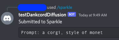
    A response from YourBotName should appear with the response Submitted to Sparkle: YourPromptHere, as shown in Figure 4.

    First response from AWS Lambda function

    Figure 4. First response from AWS Lambda function

    It will take 10 minutes for an EC2 instance to start with an ECS Task running on the instance. Once an ECS Task is running on the instance, inference times should reduce to under 30 seconds, depending on the request.
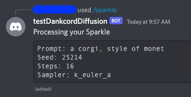
    When an ECS Task is running your request, you will see a Processing your Sparkle message, as shown in Figure 5.

    Amazon ECS task processing a request

    Figure 5. Amazon ECS task processing a request

    The message is complete when it says Completed your Sparkle! as shown in Figure 6.

    Amazon ECS task returning the final response

    Figure 6. Amazon ECS task returning the final response

Cleaning up

To avoid incurring future charges, delete the resources created by the Terraform script.

  1. Return to the directory where you deployed your terraform script.
  2. To destroy the infrastructure in AWS, run the command terraform destroy.
  3. When prompted to confirm that you want to destroy the infrastructure, type yes and press Enter.

Conclusion

In summary, we created a solution that allows members of a Discord server to create images from text with a Stable Diffusion model. With this implementation, the deployment can scale to many Discord Servers and handle over one hundred requests per second.

Create projects on AWS that lower the bar to entry for people wanting to try text to image models.

New – Amazon ECS Service Connect Enabling Easy Communication Between Microservices

Post Syndicated from Channy Yun original https://aws.amazon.com/blogs/aws/new-amazon-ecs-service-connect-enabling-easy-communication-between-microservices/

Microservices architectures are a well-known software development approach to make applications composed of small independent services that communicate over well-defined application programming interfaces (APIs). Customers faced challenges when they started breaking down their monolith applications into microservices, as it required specialized networking knowledge to communicate internally with other microservices.

Amazon Elastic Container Services (Amazon ECS) customers have several solutions for service-to-service, but each one comes with some challenges and complications: 1) Elastic Load Balancing (ELB) needs to carefully plan for configuring infrastructure for high availability and incur additional infrastructure cost. 2) Using Amazon ECS Service Discovery often requires developers to write custom application code for collecting traffic metrics and for making network calls resilient. 3) Service mesh solutions such as AWS App Mesh run outside of Amazon ECS despite having advanced traffic monitoring and routing features between services.

Today, we are announcing the general availability of Amazon ECS Service Connect, a new capability that simplifies building and operating resilient distributed applications. ECS Service Connect provides an easy network setup and seamless service communication deployed across multiple ECS clusters and virtual private clouds (VPCs). You can add a layer of resilience to your ECS service communication and get traffic insights with no changes to your application code.

With ECS Service Connect, you can refer and connect to your services by logical names using a namespace provided by AWS Cloud Map and automatically distribute traffic between ECS tasks without deploying and configuring load balancers. You can set some safe defaults for traffic resilience, such as health checking, automatic retries for 503 errors, and connection draining, for each of your ECS services. Additionally, the Amazon ECS console provides easy-to-use dashboards with real-time network traffic metrics for operational convenience and simplified debugging.

Getting Started with Amazon ECS Service Connect
To get started with the ECS Service Connect, you can specify a namespace as part of creating an ECS cluster or create one in the Cloud Map. A namespace represents a way to structure your services and can span across multiple ECS clusters residing in different VPCs. All ECS services that belong to a specific namespace can communicate with existing services in the namespaces, provided existing network-level connectivity.

You can also see a list of Cloud Map namespaces in Namespaces in the left navigation pane of the Amazon ECS console. When you select a namespace, it shows a list of services with the same namespace from two different ECS clusters with database services (db-mysql, db-redis) and backend services (webui, appserver).

When you create an ECS cluster, you can select one of the namespaces in the Default namespaces of the Networking setting. ECS Service Connect is enabled for all new ECS services running in both AWS Fargate and Amazon EC2 instances. To enable all existing services, you would need to redeploy with either a new version of ECS-optimized Amazon Machine Image (AMI), or with a new Fargate Agent that supports ECS Service Connect.

Or, you can simply create a cluster via AWS Command Line Interface (AWS CLI) with serviceConnect parameter and a default Cloud Map namespace name for service discovery purposes.

$ aws ecs create-cluster
     --cluster "svc-cluster-2"
     --serviceConnect {
       "defaultNamespace": "svc-namespace"
}

This command will create an ECS cluster with the namespace on AWS’s behalf. If you would like to use an already existing Cloud Map namespace, you can simply pass the name of the existing namespace here.

Next, let’s create a service with a task definition and expose your web user-interface server using ECS Service Connect.

$ aws ecs create-service
--cluster "svc-cluster-2"
--service-name "webui"
--task-definition "webui-svc-cluster"
--serviceConnect {
  "enabled": true,
  "namespace": "svc-namespace",
  "services":
   [
      {
         "portName": "webui-port",
         "discoveryName": "webui-svc",
         "clientAliases": [
           {
              "port": 80, // *Required *//
              "dnsName": "webui-svc-domain" // * Optional *//
            }
        }
     ]
   ]
}

In this command, portName represents a reference to the container port, and clientAliases assigns the port number and DNS name, overriding the discovery name that is used in the endpoint. Each service has an endpoint URL that contains the protocol, a DNS name, and the port. You can select the protocol and port name in the task definition or the ECS service configuration. For example, an endpoint could be http://webui:80, grpc://appserver:8080, or http://db-redis:8888.

In the ECS console, you can see this configuration of ECS Service Connect for the webui service in the svc-cluster-2 cluster.

As you can see, you can run the same workloads across different clusters with the same clientAlias and namespace name for high availability. ECS Service Connect will intelligently load balance the traffic to the ECS tasks. To connect to services running in different ECS clusters, you need to specify the same namespace name for all your ECS services that need to talk to each other. ECS Service Connect will make your services discoverable to all other services in the same namespace.

Improving Service Resilience with Observability Data
You can collect traffic metrics with ECS Service Connect observability capabilities. By default, for each ECS service, you can see the number of healthy and unhealthy endpoints, along with inbound and outbound traffic volume.

ECS Service Connect supports HTTP/1, HTTP/2, gRPC, and TCP protocols. So, you can collect the number of requests, number of HTTP errors, and average call latency. For gRPC and TCP, you can see the total number of active connections. All of these metrics are pushed to Amazon CloudWatch or other AWS analytics services via custom log routing

In the Advanced menu, you can publish ECS Service Connect Agent logs for help in debugging in case of issues.

These metrics are only visible in the original interface of the CloudWatch console. When you use the CloudWatch console, switch to the original interface to see the additional metric dimensions of “discovery name” and “target discovery name” under the ECS grouping.

The default settings provide you with a starting point for building resilient applications, and you can fine-tune parameters to limit the impact of failures, latency spikes, and network fluctuations on your application behavior using AWS Management Console or dedicated ECS APIs.

Now Available
Amazon ECS Service Connect is available in all commercial Regions, except China, where Amazon ECS is available. ECS Service Connect is fully supported in AWS CloudFormation, AWS CDK, AWS Copilot, and AWS Proton for infrastructure provisioning, code deployments, and monitoring of your services. To learn more, see the Amazon ECS Service Connect Developer Guide.

My colleagues, Hemanth AVS, Senior Container Specialist SA, and Satya Vajrapu, Senior DevOps Consultant, prepared a hands-on workshop to demonstrate an example of the ECS Service Connect. Join CON303 Networking, service mesh, and service discovery with Amazon ECS when you attend AWS re:Invent 2022.

Give it a try, and please send feedback to AWS re:Post for Amazon ECS or through your usual AWS support contacts.

Channy

AWS Week in Review – November 21, 2022

Post Syndicated from Danilo Poccia original https://aws.amazon.com/blogs/aws/aws-week-in-review-november-21-2022/

This post is part of our Week in Review series. Check back each week for a quick roundup of interesting news and announcements from AWS!

A new week starts, and the News Blog team is getting ready for AWS re:Invent! Many of us will be there next week and it would be great to meet in person. If you’re coming, do you know about PeerTalk? It’s an onsite networking program for re:Invent attendees available through the AWS Events mobile app (which you can get on Google Play or Apple App Store) to help facilitate connections among the re:Invent community.

If you’re not coming to re:Invent, no worries, you can get a free online pass to watch keynotes and leadership sessions.

Last Week’s Launches
It was a busy week for our service teams! Here are the launches that got my attention:

AWS Region in Spain – The AWS Region in Aragón, Spain, is now open. The official name is Europe (Spain), and the API name is eu-south-2.

Amazon Athena – You can now apply AWS Lake Formation fine-grained access control policies with all table and file format supported by Amazon Athena to centrally manage permissions and access data catalog resources in your Amazon Simple Storage Service (Amazon S3) data lake. With fine-grained access control, you can restrict access to data in query results using data filters to achieve column-level, row-level, and cell-level security.

Amazon EventBridge – With these additional filtering capabilities, you can now filter events by suffix, ignore case, and match if at least one condition is true. This makes it easier to write complex rules when building event-driven applications.

AWS Controllers for Kubernetes (ACK) – The ACK for Amazon Elastic Compute Cloud (Amazon EC2) is now generally available and lets you provision and manage EC2 networking resources, such as VPCs, security groups and internet gateways using the Kubernetes API. Also, the ACK for Amazon EMR on EKS is now generally available to allow you to declaratively define and manage EMR on EKS resources such as virtual clusters and job runs as Kubernetes custom resources. Learn more about ACK for Amazon EMR on EKS in this blog post.

Amazon HealthLake – New analytics capabilities make it easier to query, visualize, and build machine learning (ML) models. Now HealthLake transforms customer data into an analytics-ready format in near real-time so that you can query, and use the resulting data to build visualizations or ML models. Also new is Amazon HealthLake Imaging (preview), a new HIPAA-eligible capability that enables you to easily store, access, and analyze medical images at any scale. More on HealthLake Imaging can be found in this blog post.

Amazon RDS – You can now transfer files between Amazon Relational Database Service (RDS) for Oracle and an Amazon Elastic File System (Amazon EFS) file system. You can use this integration to stage files like Oracle Data Pump export files when you import them. You can also use EFS to share a file system between an application and one or more RDS Oracle DB instances to address specific application needs.

Amazon ECS and Amazon EKS – We added centralized logging support for Windows containers to help you easily process and forward container logs to various AWS and third-party destinations such as Amazon CloudWatch, S3, Amazon Kinesis Data Firehose, Datadog, and Splunk. See these blog posts for how to use this new capability with ECS and with EKS.

AWS SAM CLI – You can now use the Serverless Application Model CLI to locally test and debug an AWS Lambda function defined in a Terraform application. You can see a walkthrough in this blog post.

AWS Lambda – Now supports Node.js 18 as both a managed runtime and a container base image, which you can learn more about in this blog post. Also check out this interesting article on why and how you should use AWS SDK for JavaScript V3 with Node.js 18. And last but not least, there is new tooling support to build and deploy native AOT compiled .NET 7 applications to AWS Lambda. With this tooling, you can enable faster application starts and benefit from reduced costs through the faster initialization times and lower memory consumption of native AOT applications. Learn more in this blog post.

AWS Step Functions – Now supports cross-account access for more than 220 AWS services to process data, automate IT and business processes, and build applications across multiple accounts. Learn more in this blog post.

AWS Fargate – Adds the ability to monitor the utilization of the ephemeral storage attached to an Amazon ECS task. You can track the storage utilization with Amazon CloudWatch Container Insights and ECS Task Metadata endpoint.

AWS Proton – Now has a centralized dashboard for all resources deployed and managed by AWS Proton, which you can learn more about in this blog post. You can now also specify custom commands to provision infrastructure from templates. In this way, you can manage templates defined using the AWS Cloud Development Kit (AWS CDK) and other templating and provisioning tools. More on CDK support and AWS CodeBuild provisioning can be found in this blog post.

AWS IAM – You can now use more than one multi-factor authentication (MFA) device for root account users and IAM users in your AWS accounts. More information is available in this post.

Amazon ElastiCache – You can now use IAM authentication to access Redis clusters. With this new capability, IAM users and roles can be associated with ElastiCache for Redis users to manage their cluster access.

Amazon WorkSpaces – You can now use version 2.0 of the WorkSpaces Streaming Protocol (WSP) host agent that offers significant streaming quality and performance improvements, and you can learn more in this blog post. Also, with Amazon WorkSpaces Multi-Region Resilience, you can implement business continuity solutions that keep users online and productive with less than 30-minute recovery time objective (RTO) in another AWS Region during disruptive events. More on multi-region resilience is available in this post.

Amazon CloudWatch RUM – You can now send custom events (in addition to predefined events) for better troubleshooting and application specific monitoring. In this way, you can monitor specific functions of your application and troubleshoot end user impacting issues unique to the application components.

AWS AppSync – You can now define GraphQL API resolvers using JavaScript. You can also mix functions written in JavaScript and Velocity Template Language (VTL) inside a single pipeline resolver. To simplify local development of resolvers, AppSync released two new NPM libraries and a new API command. More info can be found in this blog post.

AWS SDK for SAP ABAP – This new SDK makes it easier for ABAP developers to modernize and transform SAP-based business processes and connect to AWS services natively using the SAP ABAP language. Learn more in this blog post.

AWS CloudFormation – CloudFormation can now send event notifications via Amazon EventBridge when you create, update, or delete a stack set.

AWS Console – With the new Applications widget on the Console home, you have one-click access to applications in AWS Systems Manager Application Manager and their resources, code, and related data. From Application Manager, you can view the resources that power your application and your costs using AWS Cost Explorer.

AWS Amplify – Expands Flutter support (developer preview) to Web and Desktop for the API, Analytics, and Storage use cases. You can now build cross-platform Flutter apps with Amplify that target iOS, Android, Web, and Desktop (macOS, Windows, Linux) using a single codebase. Learn more on Flutter Web and Desktop support for AWS Amplify in this post. Amplify Hosting now supports fully managed CI/CD deployments and hosting for server-side rendered (SSR) apps built using Next.js 12 and 13. Learn more in this blog post and see how to deploy a NextJS 13 app with the AWS CDK here.

Amazon SQS – With attribute-based access control (ABAC), you can define permissions based on tags attached to users and AWS resources. With this release, you can now use tags to configure access permissions and policies for SQS queues. More details can be found in this blog.

AWS Well-Architected Framework – The latest version of the Data Analytics Lens is now available. The Data Analytics Lens is a collection of design principles, best practices, and prescriptive guidance to help you running analytics on AWS.

AWS Organizations – You can now manage accounts, organizational units (OUs), and policies within your organization using CloudFormation templates.

For a full list of AWS announcements, be sure to keep an eye on the What’s New at AWS page.

Other AWS News
A few more stuff you might have missed:

Introducing our final AWS Heroes of the year – As the end of 2022 approaches, we are recognizing individuals whose enthusiasm for knowledge-sharing has a real impact with the AWS community. Please meet them here!

The Distributed Computing ManifestoWerner Vogles, VP & CTO at Amazon.com, shared the Distributed Computing Manifesto, a canonical document from the early days of Amazon that transformed the way we built architectures and highlights the challenges faced at the end of the 20th century.

AWS re:Post – To make this community more accessible globally, we expanded the user experience to support five additional languages. You can now interact with AWS re:Post also using Traditional Chinese, Simplified Chinese, French, Japanese, and Korean.

For AWS open-source news and updates, here’s the latest newsletter curated by Ricardo to bring you the most recent updates on open-source projects, posts, events, and more.

Upcoming AWS Events
As usual, there are many opportunities to meet:

AWS re:Invent – Our yearly event is next week from November 28 to December 2. If you can’t be there in person, get your free online pass to watch live the keynotes and the leadership sessions.

AWS Community DaysAWS Community Day events are community-led conferences to share and learn together. Join us in Sri Lanka (on December 6-7), Dubai, UAE (December 10), Pune, India (December 10), and Ahmedabad, India (December 17).

That’s all from me for this week. Next week we’ll focus on re:Invent, and then we’ll take a short break. We’ll be back with the next Week in Review on December 12!

Danilo

How Launchmetrics improves fashion brands performance using Amazon EC2 Spot Instances

Post Syndicated from Ivo Pinto original https://aws.amazon.com/blogs/architecture/how-launchmetrics-improves-fashion-brands-performance-using-amazon-ec2-spot-instances/

Launchmetrics offers its Brand Performance Cloud tools and intelligence to help fashion, luxury, and beauty retail executives optimize their global strategy. Launchmetrics initially operated their whole infrastructure on-premises; however, they wanted to scale their data ingestion while simultaneously providing improved and faster insights for their clients. These business needs led them to build their architecture in AWS cloud.

In this blog post, we explain how Launchmetrics’ uses Amazon Web Services (AWS) to crawl the web for online social and print media. Using the data gathered, Launchmetrics is able to provide prescriptive analytics and insights to their clients. As a result, clients can understand their brand’s momentum and interact with their audience, successfully launching their products.

Architecture overview

Launchmetrics’ platform architecture is represented in Figure 1 and composed of three tiers:

  1. Crawl
  2. Data Persistence
  3. Processing
Launchmetrics backend architecture

Figure 1. Launchmetrics backend architecture

The Crawl tier is composed of several Amazon Elastic Compute Cloud (Amazon EC2) Spot Instances launched via Auto Scaling groups. Spot Instances take advantage of unused Amazon EC2 capacity at a discounted rate compared with On-Demand Instances, which are compute instances that are billed per-hour or -second with no long-term commitments. Launchmetrics heavily leverages Spot Instances. The Crawl tier is responsible for retrieving, processing, and storing data from several media sources (represented in Figure 1 with the number 1).

The Data Persistence tier consists of two components: Amazon Kinesis Data Streams and Amazon Simple Queue Service (Amazon SQS). Kinesis Data Streams stores data that the Crawl tier collects, while Amazon SQS stores the metadata of the whole process. In this context, metadata helps Launchmetrics gain insight into when the data is collected and if it has started processing. This is key information if a Spot Instance is interrupted, which we will dive deeper into later.

The third tier, Processing, also makes use of Spot Instances and is responsible for pulling data from the Data Persistence tier (represented in Figure 1 with the number 2). It then applies proprietary algorithms, both analytics and machine learning models, to create consumer insights. These insights are stored in a data layer (not depicted) that consists of an Amazon Aurora cluster and an Amazon OpenSearch Service cluster.

By having this separation of tiers, Launchmetrics is able to use a decoupled architecture, where each component can scale independently and is more reliable. Both the Crawl and the Data Processing tiers use Spot Instances for up to 90% of their capacity.

Data processing using EC2 Spot Instances

When Launchmetrics decided to migrate their workloads to the AWS cloud, Spot Instances were one of the main drivers. As Spot Instances offer large discounts without commitment, Launchmetrics was able to track more than 1200 brands, translating to 1+ billion end users. Daily, this represents tracking upwards of 500k influencer profiles, 8 million documents, and around 70 million social media comments.

Aside from the cost-savings with Spot Instances, Launchmetrics incurred collateral benefits in terms of architecture design: building stateless, decoupled, elastic, and fault-tolerant applications. In turn, their stack architecture became more loosely coupled, as well.

All Launchmetrics Auto Scaling groups have the following configuration:

  • Spot allocation strategy: cost-optimized
  • Capacity rebalance: true
  • Three availability zones
  • A diversified list of instance types

By using Auto Scaling groups, Launchmetrics is able to scale worker instances depending on how many items they have in the SQS queue, increasing the instance efficiency. Data processing workloads like the ones Launchmetrics’ platform have, are an exemplary use of multiple instance types, such as M5, M5a, C5, and C5a. When adopting Spot Instances, Launchmetrics considered other instance types to have access to spare capacity. As a result, Launchmetrics found out that workload’s performance improved, as they use instances with more resources at a lower cost.

By decoupling their data processing workload using SQS queues, processes are stopped when an interruption arrives. As the Auto Scaling group launches a replacement Spot Instance, clients are not impacted and data is not lost. All processes go through a data checkpoint, where a new Spot Instance resumes processing any pending data. Spot Instances have resulted in a reduction of up to 75% of related operational costs.

To increase confidence in their ability to deal with Spot interruptions and service disruptions, Launchmetrics is exploring using AWS Fault Injection Simulator to simulate faults on their architecture, like a Spot interruption. Learn more about how this service works on the AWS Fault Injection Simulator now supports Spot Interruptions launch page.

Reporting data insights

After processing data from different media sources, AWS aided Launchmetrics in producing higher quality data insights, faster: the previous on-premises architecture had a time range of 5-6 minutes to run, whereas the AWS-driven architecture takes less than 1 minute.

This is made possible by elasticity and availability compute capacity that Amazon EC2 provides compared with an on-premises static fleet. Furthermore, offloading some management and operational tasks to AWS by using AWS managed services, such as Amazon Aurora or Amazon OpenSearch Service, Launchmetrics can focus on their core business and improve proprietary solutions rather than use that time in undifferentiated activities.

Building continuous delivery pipelines

Let’s discuss how Launchmetrics makes changes to their software with so many components.

Both of their computing tiers, Crawl and Processing, consist of standalone EC2 instances launched via Auto Scaling groups and EC2 instances that are part of an Amazon Elastic Container Service (Amazon ECS) cluster. Currently, 70% of Launchmetrics workloads are still running with Auto Scaling groups, while 30% are containerized and run on Amazon ECS. This is important because for each of these workload groups, the deployment process is different.

For workloads that run on Auto Scaling groups, they use an AWS CodePipeline to orchestrate the whole process, which includes:

I.  Creating a new Amazon Machine Image (AMI) using AWS CodeBuild
II. Deploying the newly built AMI using Terraform in CodeBuild

For containerized workloads that run on Amazon ECS, Launchmetrics also uses a CodePipeline to orchestrate the process by:

III. Creating a new container image, and storing it in Amazon Elastic Container Registry
IV. Changing the container image in the task definition, and updating the Amazon ECS service using CodeBuild

Conclusion

In this blog post, we explored how Launchmetrics is using EC2 Spot Instances to reduce costs while producing high-quality data insights for their clients. We also demonstrated how decoupling an architecture is important for handling interruptions and why following Spot Instance best practices can grant access to more spare capacity.

Using this architecture, Launchmetrics produced faster, data-driven insights for their clients and increased their capacity to innovate. They are continuing to containerize their applications and are projected to have 100% of their workloads running on Amazon ECS with Spot Instances by the end of 2023.

To learn more about handling EC2 Spot Instance interruptions, visit the AWS Best practices for handling EC2 Spot Instance interruptions blog post. Likewise, if you are interested in learning more about AWS Fault Injection Simulator and how it can benefit your architecture, read Increase your e-commerce website reliability using chaos engineering and AWS Fault Injection Simulator.

AWS Week in Review – September 19, 2022

Post Syndicated from Jeff Barr original https://aws.amazon.com/blogs/aws/aws-week-in-review-september-19-2022/

Things are heating up in Seattle, with preparation for AWS re:Invent 2022 well underway. Later this month the entire News Blog team will participate in our now-legendary “speed storming” event. Over the course of three or four days, each of the AWS service teams with a launch in the works for re:Invent will give us an overview and share their PRFAQ (Press Release + FAQ) with us. After the meetings conclude, we’ll divvy up the launches and get to work on our blog posts!

Last Week’s Launches
Here are some of the launches that caught my eye last week:

Amazon Lex Visual Conversation Builder – This new tool makes bot design easier than ever. You get a complete view of the conversation in one place, and you can manage complex conversations that have dynamic paths. To learn more and see the builder in action, read Announcing Visual Conversation Builder for Amazon Lex on the AWS Machine Learning Blog.

AWS Config Conformance Pack Price Reduction – We have reduced the price for evaluation of AWS Config Conformance Packs by up to 58%. These packs contain AWS Config rules and remediation actions that can be deployed as a single entity in account and a region, or across an entire organization. The price reduction took effect September 14, 2022; it lowers the cost per evaluation and decreases the number of evaluations needed to reach each pricing tier.

CDK (Cloud Development Kit) Tree View – The AWS CloudFormation console now includes a Constructs tree view that automatically organizes the resources that were synthesized by AWS CDK constructs. The top level of the tree view includes the named constructs and the second level includes all of the resources generated by the named construct. Read the What’s New to learn more!

AWS Incident Detection and ResponseAWS Enterprise Support customers now have access to proactive monitoring and incident management for selected workloads running on AWS. As part of the onboarding process, AWS experts review workloads for reliability and operational excellence, and work with the customer to identify critical metrics and associated alarms. Incident Management Engineers then monitor the workloads, detect critical incidents, and initiate a call bridge to accelerate recovery. Read the AWS Incident Detection and Response page and the What’s New to learn more.

ECS Cluster Scale-In Speed – Auto-Scaled ECS clusters can now scale-in (reduce capacity) faster than ever before. Previously, each scale-in would reduce the capacity within an Auto Scaling Group (ASG) by 5% at a time. Now, capacity can be reduced by up to 50%. This change makes scaling more responsive to workload changes while still maintaining availability for spiky traffic patterns. Read Faster Scaling-In for Amazon ECS Cluster Auto Scaling and the What’s New to learn more.

AWS Outposts Rack Networking – AWS Outposts racks now support local gateway ingress routing to redirect incoming traffic to an Elastic Network Interface (ENI) attached to an EC2 instance before traffic reaches workloads running on the Outpost; read Deploying Local Gateway Ingress Routing on AWS Outposts to learn more. Outposts racks now also support direct VPC routing to simplify the process of communicating with your on-premises network; read the What’s New to learn more.

Amazon SWF Console Experience Updated – The new console experience for Amazon Simple Workflow Service (SWF) gives you better visibility of your SWF domains along with additional information about your workflow executions and events. You can efficiently manage high-volume workloads and quickly find the detailed information that helps you to operate at peak efficiency. Read the What’s New to learn more.

Dynamic Intermediate Certificate Authorities – According to a post on the AWS Security Blog, public certificates issued through AWS Certificate Manager (ACM) will soon (October 11, 2022) be issued from one of several intermediate certificate authorities managed by Amazon. This change will be transparent to most customers and applications, except those that make use of certificate pinning. In some cases, older browsers will need to be updated in order to properly trust the Amazon Trust Services CAs.

X in Y – We launched existing AWS services and instance types in additional regions:

Other AWS News
AWS Open Source – Check out Installment #127 of the AWS Open Source News and Updates Newsletter to learn about new tools for AWS CloudFormation, AWS Lambda, Terraform / EKS, AWS Step Functions, AWS Identity and Access Management (IAM), and more.

New Case Study – Read this new case study to learn how the Deep Data Research Computing Center at Stanford University is creating tools designed to bridge the gap between biology and computer science in order to help researchers in precision medicine deliver tangible medical solutions.

Application Management – The AWS DevOps Blog showed you how to Implement Long-Running Deployments with AWS CloudFormation Custom Resources Using AWS Step Functions.

Architecture – The AWS Architecture Blog showed you how to Maintain Visibility Over the Use of Cloud Architecture Patterns.

Big Data – The AWS Big Data Blog showed you how to Optimize Amazon EMR Costs for Legacy and Spark Workloads.

Migration – In a two-part series on the AWS Compute Blog, Marcia showed you how to Lift and Shift a Web Application to AWS Serverless (Part 1, Part 2).

Mobile – The AWS Mobile Blog showed you how to Build Your Own Application for Route Optimization and Tracking using AWS Amplify and Amazon Location Service.

Security – The AWS Security Blog listed 10 Reasons to Import a Certificate into AWS Certificate Manager and 154 AWS Services that have achieved HITRUST Certificiation.

Training and Certification – The AWS Training and Certification Blog talked about The Value of Data and Pursuing the AWS Certified Data Analytics – Specialty Certification.

Containers – The AWS Containers Blog encouraged you to Achieve Consistent Application-Level Tagging for Cost Tracking in AWS.

Upcoming AWS Events
Check your calendar and sign up for an AWS event in your locale:

AWS Summits – Come together to connect, collaborate, and learn about AWS. Registration is open for the following in-person AWS Summits: Mexico City (September 21–22), Bogotá (October 4), and Singapore (October 6).

AWS Community DaysAWS Community Day events are community-led conferences to share and learn with one another. In September, the AWS community in the US will run events in Arlington, Virginia (September 30). In Europe, Community Day events will be held in October. Join us in Amersfoort, Netherlands (October 3), Warsaw, Poland (October 14), and Dresden, Germany (October 19).

AWS Fest – This third-party event will feature AWS influencers, community heroes, industry leaders, and AWS customers, all sharing AWS optimization secrets (September 29th), register here.

Stay Informed
I hope that you have enjoyed this look back at some of what took place in AWS-land last week! To better keep up with all of this news, please check out the following resources:

Jeff;

Choosing an AWS container service to run your modern application

Post Syndicated from Lewis Tang original https://aws.amazon.com/blogs/architecture/choosing-an-aws-container-service-to-run-your-modern-application/

Businesses want to innovate quickly and deliver value even faster. To achieve these goals, the platform needs to enable teams to focus on delivering applications that are reliable, secure, highly available, cost-efficient, and scalable to required sizes.

Consider including containers on AWS in your platform, whether you are trying containers for the first time, spinning out parts of an on-premises solution to microservices in the cloud, or are new to the cloud. Containers can help you achieving a range of business benefits, including increased scalability, agility, flexibility, and cost efficiency.

In this post, we discuss three sets of builder expectations and how AWS container services can help to meet with your application delivery requirements and choose the appropriate container platform service on AWS.

Decrease container platform operations management overhead

If managing a platform is not your business’s strategic focus (for example, if most of your engineers are code developers), it can be preferable to only manage application development.

Amazon Lightsail containers offer a simple way for developers to deploy their containers to the cloud. With a Docker image you provide for your containers, AWS automatically deploys containerized workloads for you.

Lightsail assigns an HTTPS endpoint that is ready to serve your web application running in the cloud container. It automatically sets up a load-balanced Transport Layer Security (TLS) endpoint and takes care of the TLS certificate. This service replaces unresponsive containers for you automatically; by assigning a Domain Name System to your endpoint, Lightsail maintains the old version until the new version is healthy and ready to go live (Figure 1).

Amazon Lightsail containers

Figure 1. Amazon Lightsail containers

Another simple way to build and run your containerized web application in AWS is using AWS App Runner, which provides a fully managed container-native service.

Without orchestrators to configure, build pipelines to set up, or load balancers to optimize, you can bring existing containers or use the integrated container build service to go directly from the code repository to deployed application.

The build service can connect to a GitHub repository, providing a Git push workflow that deploys changes automatically. App Runner orchestration workflow take cares of the build, deployment, and configuration tasks, such as host, runtime patching, monitoring load balancing, and auto scaling (Figure 2). Explore AWS App Runner documentation and workshop for more details about the service.

AWS App Runner

Figure 2. AWS App Runner

When designing an application, you often start with a whiteboard or mental model that has representations of each service and lines for how they interact with each other. When considering an application’s platform architecture, the cloud components are not limited to virtual private cloud (VPC) subnets, load balancers, deployment pipelines, and durable storage for your application’s stateful data. Bringing all underlying cloud components together and making sure the design is well architected can be challenging.

AWS Copilot can provide guided best practices when deploying a microservice architecture that includes multiple services deployed as containers. You can use Copliot to handle cloud component details for you. By providing a container image, Copilot works with App Runner or Amazon Elastic Container Service (Amazon ECS) to provision cloud components, like VPC and having Copilot handle high-availability deployment, load balancer creation, and configuration.

To automate application deployment and new version release, Copilot can create a deployment pipeline so that the latest version of your application is automatically deployed every time you push a new commit to your code repository (as demonstrated in Figure 3).

AWS Copilot pipeline

Figure 3. AWS Copilot pipeline

Full-control application deployment with container orchestration

As business grows, your application portfolio grows. Some applications may require the selection of Microsoft Windows containers or deep customizations on container-resource scheduling, monitoring, and logging. To accommodate this, you need the flexibility of configuring the required underlying container services while still using the efficient container orchestrator to automate the common processes to achieve operation efficiency. This is where Amazon ECS and Amazon Elastic Kubernetes Service (Amazon EKS) can help.

Using Amazon ECS

As demonstrated in Figure 4, Amazon ECS is a highly scalable, high-performance container management service that supports containers and allows you to easily run applications on a managed cluster of Amazon Elastic Compute Cloud instances with Amazon Fargate (a serverless compute engine for containers). With this, you can launch and stop containerized applications and query the complete state of your cluster. You have the ability to access and configure many familiar features, like security groups and Elastic Load Balancing (ELB), by sending simple API calls.

Amazon ECS can be used to schedule container placement across your cluster based on resource needs and availability requirements. You can also integrate your own scheduler or third-party schedulers to meet business- or application-specific requirements.

Amazon ECS using AWS Fargate

Figure 4. Amazon ECS using AWS Fargate

Using Amazon EKS

Amazon EKS is a managed service that can be used to run Kubernetes on AWS, without installing, operating, and maintaining your own Kubernetes control plane or nodes. For many developers who have experience using Kubernetes, running Amazon EKS for application container workload is a preferred option because Amazon EKS provides the flexibility of Kubernetes with the scalability, security and resiliency of being an AWS managed service.

Amazon EKS runs and automatically scales the Kubernetes control plane across multiple AWS availability zones to ensure high availability, as in Figure 5. The control plane instances are automatically scaled based on load. Amazon EKS detects and replaces unhealthy control plane instances and provides automated version updates and patching. Amazon EKS enables developers to run up-to-date versions of the open-source Kubernetes software, the existing or new third-party plugins, and tooling. This means you can more easily migrate any standard Kubernetes application to Amazon EKS without code modification.

Scalability and security are essential to your business-critical workloads. Amazon EKS is integrated with many AWS services, including Amazon Elastic Container Registry for container images, ELB for load distribution, IAM for authentication, and Amazon Virtual Private Cloud for isolation.

Amazon EKS scales Kubernetes across multiple availability zones

Figure 5. Amazon EKS scales Kubernetes across multiple availability zones

Conclusion

To innovate and respond to changes faster, businesses need to build modern applications quickly and manage them efficiently. AWS provides container services to run your most sensitive, secure, and business-critical workloads reliably and to-scale.

With little-to-no prior container experience, developers can use Lightsail containers to run web application container workloads with easy-to-use interface. App Runner simplifies application deployment and management down into one particular service for running web applications. With Copilot, you can get step-by-step best practice guidance when you need to deploy microservice architecture with multiple services deployed as containers. Amazon ECS and Amazon EKS give the flexibility of configuring container workloads while maintaining the application deployment and operational efficiency.

Further reading

Coordinating large messages across accounts and Regions with Amazon SNS and SQS

Post Syndicated from Mrudhula Balasubramanyan original https://aws.amazon.com/blogs/architecture/coordinating-large-messages-across-accounts-and-regions-with-amazon-sns-and-sqs/

Many organizations have applications distributed across various business units. Teams in these business units may develop their applications independent of each other to serve their individual business needs. Applications can reside in a single Amazon Web Services (AWS) account or be distributed across multiple accounts. Applications may be deployed to a single AWS Region or span multiple Regions.

Irrespective of how the applications are owned and operated, these applications need to communicate with each other. Within an organization, applications tend to be part of a larger system, therefore, communication and coordination among these individual applications is critical to overall operation.

There are a number of ways to enable coordination among component applications. It can be done either synchronously or asynchronously:

  • Synchronous communication uses a traditional request-response model, in which the applications exchange information in a tightly coupled fashion, introducing multiple points of potential failure.
  • Asynchronous communication uses an event-driven model, in which the applications exchange messages as events or state changes and are loosely coupled. Loose coupling allows applications to evolve independently of each other, increasing scalability and fault-tolerance in the overall system.

Event-driven architectures use a publisher-subscriber model, in which events are emitted by the publisher and consumed by one or more subscribers.

A key consideration when implementing an event-driven architecture is the size of the messages or events that are exchanged. How can you implement an event-driven architecture for large messages, beyond the default maximum of the services? How can you architect messaging and automation of applications across AWS accounts and Regions?

This blog presents architectures for enhancing event-driven models to exchange large messages. These architectures depict how to coordinate applications across AWS accounts and Regions.

Challenge with application coordination

A challenge with application coordination is exchanging large messages. For the purposes of this post, a large message is defined as an event payload between 256 KB and 2 GB. This stems from the fact that Amazon Simple Notification Service (Amazon SNS) and Amazon Simple Queue Service (Amazon SQS) currently have a maximum event payload size of 256 KB. To exchange messages larger than 256 KB, an intermediate data store must be used.

To exchange messages across AWS accounts and Regions, set up the publisher access policy to allow subscriber applications in other accounts and Regions. In the case of large messages, also set up a central data repository and provide access to subscribers.

Figure 1 depicts a basic schematic of applications distributed across accounts communicating asynchronously as part of a larger enterprise application.

Asynchronous communication across applications

Figure 1. Asynchronous communication across applications

Architecture overview

The overview covers two scenarios:

  1. Coordination of applications distributed across AWS accounts and deployed in the same Region
  2. Coordination of applications distributed across AWS accounts and deployed to different Regions

Coordination across accounts and single AWS Region

Figure 2 represents an event-driven architecture, in which applications are distributed across AWS Accounts A, B, and C. The applications are all deployed to the same AWS Region, us-east-1. A single Region simplifies the architecture, so you can focus on application coordination across AWS accounts.

Application coordination across accounts and single AWS Region

Figure 2. Application coordination across accounts and single AWS Region

The application in Account A (Application A) is implemented as an AWS Lambda function. This application communicates with the applications in Accounts B and C. The application in Account B is launched with AWS Step Functions (Application B), and the application in Account C runs on Amazon Elastic Container Service (Application C).

In this scenario, Applications B and C need information from upstream Application A. Application A publishes this information as an event, and Applications B and C subscribe to an SNS topic to receive the events. However, since they are in other accounts, you must define an access policy to control who can access the SNS topic. You can use sample Amazon SNS access policies to craft your own.

If the event payload is in the 256 KB to 2 GB range, you can use Amazon Simple Storage Service (Amazon S3) as the intermediate data store for your payload. Application A uses the Amazon SNS Extended Client Library for Java to upload the payload to an S3 bucket and publish a message to an SNS topic, with a reference to the stored S3 object. The message containing the metadata must be within the SNS maximum message limit of 256 KB. Amazon EventBridge is used for routing events and handling authentication.

The subscriber Applications B and C need to de-reference and retrieve the payloads from Amazon S3. The SQS queue in Account B and Lambda function in Account C subscribe to the SNS topic in Account A. In Account B, a Lambda function is used to poll the SQS queue and read the message with the metadata. The Lambda function uses the Amazon SQS Extended Client Library for Java to retrieve the S3 object referenced in the message.

The Lambda function in Account C uses the Payload Offloading Java Common Library for AWS to get the referenced S3 object.

Once the S3 object is retrieved, the Lambda functions in Accounts B and C process the data and pass on the information to downstream applications.

This architecture uses Amazon SQS and Lambda as subscribers because they provide libraries that support offloading large payloads to Amazon S3. However, you can use any Java-enabled endpoint, such as an HTTPS endpoint that uses Payload Offloading Java Common Library for AWS to de-reference the message content.

Coordination across accounts and multiple AWS Regions

Sometimes applications are spread across AWS Regions, leading to increased latency in coordination. For existing applications, it could take substantive effort to consolidate to a single Region. Hence, asynchronous coordination would be a good fit for this scenario. Figure 3 expands on the architecture presented earlier to include multiple AWS Regions.

Application coordination across accounts and multiple AWS Regions

Figure 3. Application coordination across accounts and multiple AWS Regions

The Lambda function in Account C is in the same Region as the upstream application in Account A, but the Lambda function in Account B is in a different Region. These functions must retrieve the payload from the S3 bucket in Account A.

To provide access, configure the AWS Lambda execution role with the appropriate permissions. Make sure that the S3 bucket policy allows access to the Lambda functions from Accounts B and C.

Considerations

For variable message sizes, you can specify if payloads are always stored in Amazon S3 regardless of their size, which can help simplify the design.

If the application that publishes/subscribes large messages is implemented using the AWS Java SDK, it must be Java 8 or higher. Service-specific client libraries are also available in Python, C#, and Node.js.

An Amazon S3 Multi-Region Access Point can be an alternative to a centralized bucket for the payloads. It has not been explored in this post due to the asynchronous nature of cross-region replication.

In general, retrieval of data across Regions is slower than in the same Region. For faster retrieval, workloads should be run in the same AWS Region.

Conclusion

This post demonstrates how to use event-driven architectures for coordinating applications that need to exchange large messages across AWS accounts and Regions. The messaging and automation are enabled by the Payload Offloading Java Common Library for AWS and use Amazon S3 as the intermediate data store. These components can simplify the solution implementation and improve scalability, fault-tolerance, and performance of your applications.

Ready to get started? Explore SQS Large Message Handling.

Modernization pathways for a legacy .NET Framework monolithic application on AWS

Post Syndicated from Ramakant Joshi original https://aws.amazon.com/blogs/architecture/modernization-pathways-for-a-legacy-net-framework-monolithic-application-on-aws/

Organizations aim to deliver optimal technological solutions based on their customers’ needs. Although they may be at any stage in their cloud adoption journey, businesses often end up managing and building monolithic applications. However, there are many challenges to this solution. The internal structure of a monolithic application makes it difficult for developers to maintain code. This creates a steep learning curve for new developers and increases costs. Monoliths require multiple teams to coordinate a single large release, which increases the collaboration and knowledge transfer burden. As a business grows, a monolithic application may struggle to meet the demands of an expanding user base. To address these concerns, customers should evaluate their readiness to modernize their applications in the AWS Cloud to meet their business and technical needs.

We will discuss an approach to modernizing a monolithic three-tier application (MVC pattern): a web tier, an application tier using a .NET Framework, and a data tier with a Microsoft SQL (MSSQL) Server relational database. There are three main modernization pathways for .NET applications: rehosting, replatforming, and refactoring. We recommend following this decision matrix to assess and decide on your migration path, based on your specific requirements. For this blog, we will focus on a replatform and refactor strategy to design loosely coupled microservices, packaged as lightweight containers, and backed by a purpose-built database.

Your modernization journey

The outcomes of your organization’s approach to modernization gives you the ability to scale optimally with your customers’ demands. Let’s dive into a guided approach that achieves your goals of a modern architecture, and at the same time addresses scalability, ease of maintenance, rapid deployment cycles, and cost optimization.

This involves four steps:

  1. Break down the monolith
  2. Containerize your application
  3. Refactor to .NET 6
  4. Migrate to a purpose-built, lower-cost database engine.

1. Break down the monolith

Migration to the Amazon Web Services (AWS) Cloud has many advantages. These can include increased speed to market and business agility, new revenue opportunities, and cost savings. To take full advantage, you should continuously modernize your organization’s applications by refactoring your monolithic applications into microservices.

Decomposing a monolithic application into microservices presents technical challenges that require a solid understanding of the existing code base and context of the business domains. Several patterns are useful to incrementally transform a monolithic application into microservices and other distributed designs. However, the process of refactoring the code base is manual, risky, and time consuming.

To help developers accelerate the transformation, AWS introduced AWS Microservice Extractor for .NET. This helps breakdown architecting and refactoring applications into smaller code projects. Read how AWS Microservice Extractor for .NET helped our partner, Kloia, accelerate the modernization journey of their customers and decompose a monolith.

The next modernization pathway is to containerize your application.

2. Containerize

Why should you move to containers? Containers offer a way to help you build, test, deploy, and redeploy applications on multiple environments. Specifically, Docker Containers provide you with a reliable way to gather your application components and package them together into one build artifact. This is important because modern applications are often composed of a variety of pieces besides code, such as dependencies, binaries, or system libraries. Moving legacy .NET Framework applications to containers helps to optimize operating system utilization and achieve runtime consistency.

To accelerate this process, containerize these applications to Windows containers with AWS App2Container (A2C). A2C is a command line tool for modernizing .NET and java applications into containerized applications. A2C analyzes and builds an inventory of all applications running in virtual machines, on-premises, or in the cloud. Select the application that you want to containerize and A2C packages the application artifact and identified dependencies into container images. Here is a step-by-step article and self-paced workshop to get you started using A2C.
Once your app is containerized, you can choose to self-manage by using Amazon EC2 to host Docker with Windows containers. You can also use Amazon Elastic Container Service (ECS) or Amazon Elastic Kubernetes Service (Amazon EKS). These are fully managed container orchestration services that frees you to focus on building and managing applications instead of your underlying infrastructure. Read Amazon ECS vs Amazon EKS: making sense of AWS container services.

In the next section, we’ll discuss two primary aspects to optimizing costs in our modernization scenario:

  1. Licensing costs of running workloads on Windows servers.
  2. SQL Server licensing cost.

3. Refactor to .NET 6

To address Windows licensing costs, consider moving to a Linux environment by adopting .NET Core and using the Dockerfile for a Linux Container. Customers such as GoDataFeed benefit by porting .NET Framework applications to more recent .NET 6 and running them on AWS. The .NET team has significantly improved performance with .NET 6, including a 30–40% socket performance improvement on Linux. They have added ARM64-specific optimizations in the .NET libraries, which enable customers to run on AWS Graviton.

You may also choose to switch to a serverless option using AWS Lambda (which supports .NET 6 runtime), or run your containers on ECS with Fargate, a serverless, pay-as-you-go compute engine. AWS Fargate powered by AWS Graviton2 processors can reduce cost by up to 20%, and increase performance by up to 40% versus x86 Intel-based instances. If you need full control over an application’s underlying virtual machine (VM), operating system, storage, and patching, run .NET 6 applications on Amazon EC2 Linux instances. These are powered by the latest-generation Intel and AMD processors.

To help customers port their application to .NET 6 faster, AWS added .NET 6 support to Porting Assistant for .NET. Porting Assistant is an analysis tool that scans .NET Framework (3.5+) applications to generate a target .NET Core or .NET 6 compatibility assessment. This helps you to prioritize applications for porting based on effort required. It identifies incompatible APIs and packages from your .NET Framework applications, and finds known replacements. You can refer to a demo video that explains this process.

4. Migrate from SQL Server to a lower-cost database engine

AWS advocates that you build use case-driven, highly scalable, distributed applications suited to your specific needs. From a database perspective, AWS offers 15+ purpose-built engines to support diverse data models. Furthermore, microservices architectures employ loose coupling, so each individual microservice can independently store and retrieve information from its own data store. By deploying the database-per-service pattern, you can choose the most optimal data stores (relational or non-relational databases) for your application and business requirements.

For the purpose of this blog, we will focus on a relational database alternate for SQL Server. To address the SQL Server licensing costs, customers can consider a move to an open-source relational database engine. Amazon Relational Database Service (Amazon RDS) supports MySQL, MariaDB, and PostgreSQL. We will focus on PostgreSQL with a well-defined migration path. Amazon RDS supports two types of Postgres databases: Amazon RDS for PostgreSQL and Amazon Aurora PostgreSQL-Compatible Edition. To help you choose, read Is Amazon RDS for PostgreSQL or Amazon Aurora PostgreSQL a better choice for me?

Once you’ve decided on the Amazon RDS flavor, the next question would be “what’s the right migration strategy for me?” Consider the following:

  1. Convert your schema
  2. Migrate the data
  3. Refactor your application

Schema conversion

AWS Schema Conversion Tool (SCT) is a free tool that can help you convert your existing database from one engine to another. AWS SCT supports a number of source databases, including Microsoft SQL Server, Oracle, and MySQL. You can choose from target database engines such as Amazon Aurora PostgreSQL-Compatible Edition, or choose to set up a data lake using Amazon S3. AWS SCT provides a graphical user interface that directly connects to the source and target databases to fetch the current schema objects. When connected, you can generate a database migration assessment report to get a high-level summary of the conversion effort and action items.

Data migration

When the schema migration is complete, you can move your data from the source database to the target database. Depending on your application availability requirements, you can run a straightforward extraction job that performs a one-time copy of the source data into the new database. Or, you can use a tool that copies the current data and continues to replicate all changes until you are ready to cut over to the new database. One such tool is AWS Database Migration Service (AWS DMS) that helps you migrate relational databases, data warehouses, NoSQL databases, and other types of data stores.

With AWS DMS, you can perform one-time migrations, and you can replicate ongoing changes to keep sources and targets in sync. When the source and target databases are in sync, you can take your database offline and move your operations to the target database. Read Microsoft SQL Server To Amazon Aurora with PostgreSQL Compatibility for a playbook or use this self-guided workshop to migrate to a PostgreSQL compatible database using SCT and DMS.

Application refactoring

Each database engine has its differences and nuances, and moving to a new database engine such as PostgreSQL from MSSQL Server will require code refactoring. After the initial database migration is completed, manually rewriting application code, switching out database drivers, and verifying that the application behavior hasn’t changed requires significant effort. This involves potential risk of errors when making extensive changes to the application code.

AWS built Babelfish for Aurora PostgreSQL to simplify migrating applications from SQL Server to Amazon Aurora PostgreSQL-Compatible Edition. Babelfish for Aurora PostgreSQL is a new capability for Amazon Aurora PostgreSQL-Compatible Edition that enables Aurora to understand commands from applications written for Microsoft SQL Server. With Babelfish, Aurora PostgreSQL now understands T-SQL, Microsoft SQL Server’s proprietary SQL dialect. It supports the same communications protocol, so your apps that were originally written for SQL Server can now work with Aurora. Read about how to migrate from SQL Server to Babelfish for Aurora PostgreSQL. Make sure you run the Babelfish Compass tool to determine whether the application contains any SQL features not currently supported by Babelfish.

Figure 1 shows the before and after state for your application based on the modernization path described in this blog. The application tier consists of microservices running on Amazon ECS Fargate clusters (or AWS Lambda functions), and the data tier runs on Amazon Aurora (PostgreSQL flavor).

Figure 1. A modernized microservices-based rearchitecture

Figure 1. A modernized microservices-based rearchitecture

Summary

In this post, we showed a migration path for a monolithic .NET Framework application to a modern microservices-based stack on AWS. We discussed AWS tools to break the monolith into microservices, and containerize the application. We also discussed cost optimization strategies by moving to Linux-based systems, and using open-source database engines. If you’d like to know more about modernization strategies, read this prescriptive guide.

Migrating a self-managed message broker to Amazon SQS

Post Syndicated from Vikas Panghal original https://aws.amazon.com/blogs/architecture/migrating-a-self-managed-message-broker-to-amazon-sqs/

Amazon Payment Services is a payment service provider that operates across the Middle East and North Africa (MENA) geographic regions. Our mission is to provide online businesses with an affordable and trusted payment experience. We provide a secure online payment gateway that is straightforward and safe to use.

Amazon Payment Services has regional experts in payment processing technology in eight countries throughout the Gulf Cooperation Council (GCC) and Levant regional areas. We offer solutions tailored to businesses in their international and local currency. We are continuously improving and scaling our systems to deliver with near-real-time processing capabilities. Everything we do is aimed at creating safe, reliable, and rewarding payment networks that connect the Middle East to the rest of the world.

Our use case of message queues

Our business built a high throughput and resilient queueing system to send messages to our customers. Our implementation relied on a self-managed RabbitMQ cluster and consumers. Consumer is a software that subscribes to a topic name in the queue. When subscribed, any message published into the queue tagged with the same topic name will be received by the consumer for processing. The cluster and consumers were both deployed on Amazon Elastic Compute Cloud (Amazon EC2) instances. As our business scaled, we faced challenges with our existing architecture.

Challenges with our message queues architecture

Managing a RabbitMQ cluster with its nodes deployed inside Amazon EC2 instances came with some operational burdens. Dealing with payments at scale, managing queues, performance, and availability of our RabbitMQ cluster introduced significant challenges:

  • Managing durability with RabbitMQ queues. When messages are placed in the queue, they persist and survive server restarts. But during a maintenance window they can be lost because we were using a self-managed setup.
  • Back-pressure mechanism. Our setup lacked a back-pressure mechanism, which resulted in flooding our customers with huge number of messages in peak times. All messages published into the queue were getting sent at the same time.
  • Customer business requirements. Many customers have business requirements to delay message delivery for a defined time to serve their flow. Our architecture did not support this delay.
  • Retries. We needed to implement a back-off strategy to space out multiple retries for temporarily failed messages.
Figure 1. Amazon Payment Services’ previous messaging architecture

Figure 1. Amazon Payment Services’ previous messaging architecture

The previous architecture shown in Figure 1 was able to process a large load of messages within a reasonable delivery time. However, when the message queue built up due to network failures on the customer side, the latency of the overall flow was affected. This required manually scaling the queues, which added significant human effort, time, and overhead. As our business continued to grow, we needed to maintain a strict delivery time service level agreement (SLA.)

Using Amazon SQS as the messaging backbone

The Amazon Payment Services core team designed a solution to use Amazon Simple Queue Service (SQS) with AWS Fargate (see Figure 2.) Amazon SQS is a fully managed message queuing service that enables customers to decouple and scale microservices, distributed systems, and serverless applications. It is a highly scalable, reliable, and durable message queueing service that decreases the complexity and overhead associated with managing and operating message-oriented middleware.

Amazon SQS offers two types of message queues. SQS standard queues offer maximum throughput, best-effort ordering, and at-least-once delivery. SQS FIFO queues provide that messages are processed exactly once, in the exact order they are sent. For our application, we used SQS FIFO queues.

In SQS FIFO queues, messages are stored in partitions (a partition is an allocation of storage replicated across multiple Availability Zones within an AWS Region). With message distribution through message group IDs, we were able to achieve better optimization and partition utilization for the Amazon SQS queues. We could offer higher availability, scalability, and throughput to process messages through consumers.

Figure 2. Amazon Payment Services’ new architecture using Amazon SQS, Amazon ECS, and Amazon SNS

Figure 2. Amazon Payment Services’ new architecture using Amazon SQS, Amazon ECS, and Amazon SNS

This serverless architecture provided better scaling options for our payment processing services. This helps manage the MENA geographic region peak events for the customers without the need for capacity provisioning. Serverless architecture helps us reduce our operational costs, as we only pay when using the services. Our goals in developing this initial architecture were to achieve consistency, scalability, affordability, security, and high performance.

How Amazon SQS addressed our needs

Migrating to Amazon SQS helped us address many of our requirements and led to a more robust service. Some of our main issues included:

Losing messages during maintenance windows

While doing manual upgrades on RabbitMQ and the hosting operating system, we sometimes faced downtimes. By using Amazon SQS, messaging infrastructure became automated, reducing the need for maintenance operations.

Handling concurrency

Different customers handle messages differently. We needed a way to customize the concurrency by customer. With SQS message group ID in FIFO queues, we were able to use a tag that groups messages together. Messages that belong to the same message group are always processed one by one, in a strict order relative to the message group. Using this feature and a consistent hashing algorithm, we were able to limit the number of simultaneous messages being sent to the customer.

Message delay and handling retries

When messages are sent to the queue, they are immediately pulled and received by customers. However, many customers ask to delay their messages for preprocessing work, so we introduced a message delay timer. Some messages encounter errors that can be resubmitted. But the window between multiple retries must be delayed until we receive delivery confirmation from our customer, or until the retries limit is exceeded. Using SQS, we were able to use the ChangeMessageVisibility operation, to adjust delay times.

Scalability and affordability

To save costs, Amazon SQS FIFO queues and Amazon ECS Fargate tasks run only when needed. These services process data in smaller units and run them in parallel. They can scale up efficiently to handle peak traffic loads. This will satisfy most architectures that handle non-uniform traffic without needing additional application logic.

Secure delivery

Our service delivers messages to the customers via host-to-host secure channels. To secure this data outside our private network, we use Amazon Simple Notification Service (SNS) as our delivery mechanism. Amazon SNS provides HTTPS endpoint delivery of messages coming to topics and subscriptions. AWS enables at-rest and/or in-transit encryption for all architectural components. Amazon SQS also provides AWS Key Management Service (KMS) based encryption or service-managed encryption to encrypt the data at rest.

Performance

To quantify our product’s performance, we monitor the message delivery delay. This metric evaluates the time between sending the message and when the customer receives it from Amazon payment services. Our goal is to have the message sent to the customer in near-real time once the transaction is processed. The new Amazon SQS/ECS architecture enabled us to achieve 200 ms with p99 latency.

Summary

In this blog post, we have shown how using Amazon SQS helped transform and scale our service. We were able to offer a secure, reliable, and highly available solution for businesses. We use AWS services and technologies to run Amazon Payment Services payment gateway, and infrastructure automation to deliver excellent customer service. By using Amazon SQS and Amazon ECS Fargate, Amazon Payment Services can offer secure message delivery at scale to our customers.

How Ribbon Communications Built a Scalable, Resilient Robocall Mitigation Platform

Post Syndicated from Siva Rajamani original https://aws.amazon.com/blogs/architecture/how-ribbon-communications-built-a-scalable-resilient-robocall-mitigation-platform/

Ribbon Communications provides communications software, and IP and optical networking end-to-end solutions that deliver innovation, unparalleled scale, performance, and agility to service providers and enterprise.

Ribbon Communications is helping customers modernize their networks. In today’s data-hungry, 24/7 world, this equates to improved competitive positioning and business outcomes. Companies are migrating from on-premises equipment for telephony services and looking for equivalent as a service (aaS) offerings. But these solutions must still meet the stringent resiliency, availability, performance, and regulatory requirements of a telephony service.

The telephony world is inundated with robocalls. In the United States alone, there were an estimated 50.5 billion robocalls in 2021! In this blog post, we describe the Ribbon Identity Hub – a holistic solution for robocall mitigation. The Ribbon Identity Hub enables services that sign and verify caller identity, which is compliant to the ATIS standards under the STIR/SHAKEN framework. It also evaluates and scores calls for the probability of nuisance and fraud.

Ribbon Identity Hub is implemented in Amazon Web Services (AWS). It is a fully managed service for telephony service providers and enterprises. The solution is secure, multi-tenant, automatic scaling, and multi-Region, and enables Ribbon to offer managed services to a wide range of telephony customers. Ribbon ensures resiliency and performance with efficient use of resources in the telephony environment, where load ratios between busy and idle time can exceed 10:1.

Ribbon Identity Hub

The Ribbon Identity Hub services are separated into a data (call-transaction) plane, and a control plane.

Data plane (call-transaction)

The call-transaction processing is typically invoked on a per-call-setup basis where availability, resilience, and performance predictability are paramount. Additionally, due to high variability in load, automatic scaling is a prerequisite.

Figure 1. Data plane architecture

Figure 1. Data plane architecture

Several AWS services come together in a solution that meets all these important objectives:

  1. Amazon Elastic Container Service (ECS): The ECS services are set up for automatic scaling and span two Availability Zones. This provides the horizontal scaling capability, the self-healing capacity, and the resiliency across Availability Zones.
  2. Elastic Load Balancing – Application Load Balancer (ALB): This provides the ability to distribute incoming traffic to ECS services as the target. In addition, it also offers:
    • Seamless integration with the ECS Auto Scaling group. As the group grows, traffic is directed to the new instances only when they are ready. As traffic drops, traffic is drained from the target instances for graceful scale down.
    • Full support for canary and linear upgrades with zero downtime. Maintains full-service availability without any changes or even perception for the client devices.
  3. Amazon Simple Storage Service (S3): Transaction detail records associated with call-related requests must be securely and reliably maintained for over a year due to billing and other contractual obligations. Amazon S3 simplifies this task with high durability, lifecycle rules, and varied controls for retention.
  4. Amazon DynamoDB: Building resilient services is significantly easier when the compute processing can be stateless. Amazon DynamoDB facilitates such stateless architectures without compromise. Coupled with the availability of the Amazon DynamoDB Accelerator (DAX) caching layer, the solution can meet the extreme low latency operation requirements.
  5. AWS Key Management Service (KMS): Certain tenant configuration is highly confidential and requires elevated protection. Furthermore, the data is part of the state that must be recovered across Regions in disaster recovery scenarios. To meet the security requirements, the KMS is used for envelope encryption using per-tenant keys. Multi-Region KMS keys facilitates the secure availability of this state across Regions without the need for application-level intervention when replicating encrypted data.
  6. Amazon Route 53: For telephony services, any non-transient service failure is unacceptable. In addition to providing high degree of resiliency through Multi-AZ architecture, Identity Hub also provides Regional level high availability through its multi-Region active-active architecture. Route 53 with health checks provides for dynamic rerouting of requests within minutes to alternate Regions.

Control plane

The Identity Hub control plane is used for customer configuration, status, and monitoring. The API is REST-based. Since this is not used on a call-by-call basis, the requirements around latency and performance are less stringent, though the requirements around high resiliency and dynamic scaling still apply. In this area, ease of implementation and maintainability are key.

Figure 2. Control plane architecture

Figure 2. Control plane architecture

The following AWS services implement our control plane:

  1. Amazon API Gateway: Coupled with a custom authenticator, the API Gateway handles all the REST API credential verification and routing. Implementation of an API is transformed into implementing handlers for each resource, which is the application core of the API.
  2. AWS Lambda: All the REST API handlers are written as Lambda functions. By using the Lambda’s serverless and concurrency features, the application automatically gains self-healing and auto-scaling capabilities. There is also a significant cost advantage as billing is per millisecond of actual compute time used. This is significant for a control plane where usage is typically sparse and unpredictable.
  3. Amazon DynamoDB: A stateless architecture with Lambda and API Gateway, all persistent state must be stored in an external database. The database must match the resilience and auto-scaling characteristics of the rest of the control plane. DynamoDB easily fits the requirements here.

The customer portal, in addition to providing the user interface for control plane REST APIs, also delivers a rich set of user-customizable dashboards and reporting capability. Here again, the availability of various AWS services simplifies the implementation, and remains non-intrusive to the central call-transaction processing.

Services used here include:

  1. AWS Glue: Enables extraction and transformation of raw transaction data into a format useful for reporting and dashboarding. AWS Glue is particularly useful here as the data available is regularly expanding, and the use cases for the reporting and dashboarding increase.
  2. Amazon QuickSight: Provides all the business intelligence (BI) functionality, including the ability for Ribbon to offer separate author and reader access to their users, and implements tenant-based access separation.

Conclusion

Ribbon has successfully deployed Identity Hub to enable cloud hosted telephony services to mitigate robocalls. Telephony requirements around resiliency, performance, and capacity were not compromised. Identity Hub offers the benefits of a 24/7 fully managed service requiring no additional customer on-premises equipment.

Choosing AWS services for Identity Hub gives Ribbon the ability to scale and meet future growth. The ability to dynamically scale the service in and out also brings significant cost advantages in telephony applications where busy hour traffic is significantly higher than idle time traffic. In addition, the availability of global AWS services facilitates the deployment of services in customer-local geographic locations to meet performance requirements or local regulatory compliance.

Unify log aggregation and analytics across compute platforms

Post Syndicated from Hari Ohm Prasath original https://aws.amazon.com/blogs/big-data/unify-log-aggregation-and-analytics-across-compute-platforms/

Our customers want to make sure their users have the best experience running their application on AWS. To make this happen, you need to monitor and fix software problems as quickly as possible. Doing this gets challenging with the growing volume of data needing to be quickly detected, analyzed, and stored. In this post, we walk you through an automated process to aggregate and monitor logging-application data in near-real time, so you can remediate application issues faster.

This post shows how to unify and centralize logs across different computing platforms. With this solution, you can unify logs from Amazon Elastic Compute Cloud (Amazon EC2), Amazon Elastic Container Service (Amazon ECS), Amazon Elastic Kubernetes Service (Amazon EKS), Amazon Kinesis Data Firehose, and AWS Lambda using agents, log routers, and extensions. We use Amazon OpenSearch Service (successor to Amazon Elasticsearch Service) with OpenSearch Dashboards to visualize and analyze the logs, collected across different computing platforms to get application insights. You can deploy the solution using the AWS Cloud Development Kit (AWS CDK) scripts provided as part of the solution.

Customer benefits

A unified aggregated log system provides the following benefits:

  • A single point of access to all the logs across different computing platforms
  • Help defining and standardizing the transformations of logs before they get delivered to downstream systems like Amazon Simple Storage Service (Amazon S3), Amazon OpenSearch Service, Amazon Redshift, and other services
  • The ability to use Amazon OpenSearch Service to quickly index, and OpenSearch Dashboards to search and visualize logs from its routers, applications, and other devices

Solution overview

In this post, we use the following services to demonstrate log aggregation across different compute platforms:

  • Amazon EC2 – A web service that provides secure, resizable compute capacity in the cloud. It’s designed to make web-scale cloud computing easier for developers.
  • Amazon ECS – A web service that makes it easy to run, scale, and manage Docker containers on AWS, designed to make the Docker experience easier for developers.
  • Amazon EKS – A web service that makes it easy to run, scale, and manage Docker containers on AWS.
  • Kinesis Data Firehose – A fully managed service that makes it easy to stream data to Amazon S3, Amazon Redshift, or Amazon OpenSearch Service.
  • Lambda – A compute service that lets you run code without provisioning or managing servers. It’s designed to make web-scale cloud computing easier for developers.
  • Amazon OpenSearch Service – A fully managed service that makes it easy for you to perform interactive log analytics, real-time application monitoring, website search, and more.

The following diagram shows the architecture of our solution.

The architecture uses various log aggregation tools such as log agents, log routers, and Lambda extensions to collect logs from multiple compute platforms and deliver them to Kinesis Data Firehose. Kinesis Data Firehose streams the logs to Amazon OpenSearch Service. Log records that fail to get persisted in Amazon OpenSearch service will get written to AWS S3. To scale this architecture, each of these compute platforms streams the logs to a different Firehose delivery stream, added as a separate index, and rotated every 24 hours.

The following sections demonstrate how the solution is implemented on each of these computing platforms.

Amazon EC2

The Kinesis agent collects and streams logs from the applications running on EC2 instances to Kinesis Data Firehose. The agent is a standalone Java software application that offers an easy way to collect and send data to Kinesis Data Firehose. The agent continuously monitors files and sends logs to the Firehose delivery stream.

BDB-1742-Ec2

The AWS CDK script provided as part of this solution deploys a simple PHP application that generates logs under the /etc/httpd/logs directory on the EC2 instance. The Kinesis agent is configured via /etc/aws-kinesis/agent.json to collect data from access_logs and error_logs, and stream them periodically to Kinesis Data Firehose (ec2-logs-delivery-stream).

Because Amazon OpenSearch Service expects data in JSON format, you can add a call to a Lambda function to transform the log data to JSON format within Kinesis Data Firehose before streaming to Amazon OpenSearch Service. The following is a sample input for the data transformer:

46.99.153.40 - - [29/Jul/2021:15:32:33 +0000] "GET / HTTP/1.1" 200 173 "-" "Mozilla/5.0 (Windows NT 6.1; WOW64) AppleWebKit/537.36 (KHTML, like Gecko) Chrome/51.0.2704.103 Safari/537.36"

The following is our output:

{
    "logs" : "46.99.153.40 - - [29/Jul/2021:15:32:33 +0000] \"GET / HTTP/1.1\" 200 173 \"-\" \"Mozilla/5.0 (Windows NT 6.1; WOW64) AppleWebKit/537.36 (KHTML, like Gecko) Chrome/51.0.2704.103 Safari/537.36\"",
}

We can enhance the Lambda function to extract the timestamp, HTTP, and browser information from the log data, and store them as separate attributes in the JSON document.

Amazon ECS

In the case of Amazon ECS, we use FireLens to send logs directly to Kinesis Data Firehose. FireLens is a container log router for Amazon ECS and AWS Fargate that gives you the extensibility to use the breadth of services at AWS or partner solutions for log analytics and storage.

BDB-1742-ECS

The architecture hosts FireLens as a sidecar, which collects logs from the main container running an httpd application and sends them to Kinesis Data Firehose and streams to Amazon OpenSearch Service. The AWS CDK script provided as part of this solution deploys a httpd container hosted behind an Application Load Balancer. The httpd logs are pushed to Kinesis Data Firehose (ecs-logs-delivery-stream) through the FireLens log router.

Amazon EKS

With the recent announcement of Fluent Bit support for Amazon EKS, you no longer need to run a sidecar to route container logs from Amazon EKS pods running on Fargate. With the new built-in logging support, you can select a destination of your choice to send the records to. Amazon EKS on Fargate uses a version of Fluent Bit for AWS, an upstream conformant distribution of Fluent Bit managed by AWS.

BDB-1742-EKS

The AWS CDK script provided as part of this solution deploys an NGINX container hosted behind an internal Application Load Balancer. The NGINX container logs are pushed to Kinesis Data Firehose (eks-logs-delivery-stream) through the Fluent Bit plugin.

Lambda

For Lambda functions, you can send logs directly to Kinesis Data Firehose using the Lambda extension. You can deny the records being written to Amazon CloudWatch.

BDB-1742-Lambda

After deployment, the workflow is as follows:

  1. On startup, the extension subscribes to receive logs for the platform and function events. A local HTTP server is started inside the external extension, which receives the logs.
  2. The extension buffers the log events in a synchronized queue and writes them to Kinesis Data Firehose via PUT records.
  3. The logs are sent to downstream systems.
  4. The logs are sent to Amazon OpenSearch Service.

The Firehose delivery stream name gets specified as an environment variable (AWS_KINESIS_STREAM_NAME).

For this solution, because we’re only focusing on collecting the run logs of the Lambda function, the data transformer of the Kinesis Data Firehose delivery stream filters out the records of type function ("type":"function") before sending it to Amazon OpenSearch Service.

The following is a sample input for the data transformer:

[
   {
      "time":"2021-07-29T19:54:08.949Z",
      "type":"platform.start",
      "record":{
         "requestId":"024ae572-72c7-44e0-90f5-3f002a1df3f2",
         "version":"$LATEST"
      }
   },
   {
      "time":"2021-07-29T19:54:09.094Z",
      "type":"platform.logsSubscription",
      "record":{
         "name":"kinesisfirehose-logs-extension-demo",
         "state":"Subscribed",
         "types":[
            "platform",
            "function"
         ]
      }
   },
   {
      "time":"2021-07-29T19:54:09.096Z",
      "type":"function",
      "record":"2021-07-29T19:54:09.094Z\tundefined\tINFO\tLoading function\n"
   },
   {
      "time":"2021-07-29T19:54:09.096Z",
      "type":"platform.extension",
      "record":{
         "name":"kinesisfirehose-logs-extension-demo",
         "state":"Ready",
         "events":[
            "INVOKE",
            "SHUTDOWN"
         ]
      }
   },
   {
      "time":"2021-07-29T19:54:09.097Z",
      "type":"function",
      "record":"2021-07-29T19:54:09.097Z\t024ae572-72c7-44e0-90f5-3f002a1df3f2\tINFO\tvalue1 = value1\n"
   },   
   {
      "time":"2021-07-29T19:54:09.098Z",
      "type":"platform.runtimeDone",
      "record":{
         "requestId":"024ae572-72c7-44e0-90f5-3f002a1df3f2",
         "status":"success"
      }
   }
]

Prerequisites

To implement this solution, you need the following prerequisites:

Build the code

Check out the AWS CDK code by running the following command:

mkdir unified-logs && cd unified-logs
git clone https://github.com/aws-samples/unified-log-aggregation-and-analytics .

Build the lambda extension by running the following command:

cd lib/computes/lambda/extensions
chmod +x extension.sh
./extension.sh
cd ../../../../

Make sure to replace default AWS region specified under the value of firehose.endpoint attribute inside lib/computes/ec2/ec2-startup.sh.

Build the code by running the following command:

yarn install && npm run build

Deploy the code

If you’re running AWS CDK for the first time, run the following command to bootstrap the AWS CDK environment (provide your AWS account ID and AWS Region):

cdk bootstrap \
    --cloudformation-execution-policies arn:aws:iam::aws:policy/AdministratorAccess \
    aws://<AWS Account Id>/<AWS_REGION>

You only need to bootstrap the AWS CDK one time (skip this step if you have already done this).

Run the following command to deploy the code:

cdk deploy --requires-approval

You get the following output:

 ✅  CdkUnifiedLogStack

Outputs:
CdkUnifiedLogStack.ec2ipaddress = xx.xx.xx.xx
CdkUnifiedLogStack.ecsloadbalancerurl = CdkUn-ecsse-PY4D8DVQLK5H-xxxxx.us-east-1.elb.amazonaws.com
CdkUnifiedLogStack.ecsserviceLoadBalancerDNS570CB744 = CdkUn-ecsse-PY4D8DVQLK5H-xxxx.us-east-1.elb.amazonaws.com
CdkUnifiedLogStack.ecsserviceServiceURL88A7B1EE = http://CdkUn-ecsse-PY4D8DVQLK5H-xxxx.us-east-1.elb.amazonaws.com
CdkUnifiedLogStack.eksclusterClusterNameCE21A0DB = ekscluster92983EFB-d29892f99efc4419bc08534a3d253160
CdkUnifiedLogStack.eksclusterConfigCommand515C0544 = aws eks update-kubeconfig --name ekscluster92983EFB-d29892f99efc4419bc08534a3d253160 --region us-east-1 --role-arn arn:aws:iam::xxx:role/CdkUnifiedLogStack-clustermasterroleCD184EDB-12U2TZHS28DW4
CdkUnifiedLogStack.eksclusterGetTokenCommand3C33A2A5 = aws eks get-token --cluster-name ekscluster92983EFB-d29892f99efc4419bc08534a3d253160 --region us-east-1 --role-arn arn:aws:iam::xxx:role/CdkUnifiedLogStack-clustermasterroleCD184EDB-12U2TZHS28DW4
CdkUnifiedLogStack.elasticdomainarn = arn:aws:es:us-east-1:xxx:domain/cdkunif-elasti-rkiuv6bc52rp
CdkUnifiedLogStack.s3bucketname = cdkunifiedlogstack-logsfailederrcapturebucket0bcc-xxxxx
CdkUnifiedLogStack.samplelambdafunction = CdkUnifiedLogStack-LambdatransformerfunctionFA3659-c8u392491FrW

Stack ARN:
arn:aws:cloudformation:us-east-1:xxxx:stack/CdkUnifiedLogStack/6d53ef40-efd2-11eb-9a9d-1230a5204572

AWS CDK takes care of building the required infrastructure, deploying the sample application, and collecting logs from different sources to Amazon OpenSearch Service.

The following is some of the key information about the stack:

  • ec2ipaddress – The public IP address of the EC2 instance, deployed with the sample PHP application
  • ecsloadbalancerurl – The URL of the Amazon ECS Load Balancer, deployed with the httpd application
  • eksclusterClusterNameCE21A0DB – The Amazon EKS cluster name, deployed with the NGINX application
  • samplelambdafunction – The sample Lambda function using the Lambda extension to send logs to Kinesis Data Firehose
  • opensearch-domain-arn – The ARN of the Amazon OpenSearch Service domain

Generate logs

To visualize the logs, you first need to generate some sample logs.

  1. To generate Lambda logs, invoke the function using the following AWS CLI command (run it a few times):
aws lambda invoke \
--function-name "<<samplelambdafunction>>" \
--payload '{"payload": "hello"}' /tmp/invoke-result \
--cli-binary-format raw-in-base64-out \
--log-type Tail

Make sure to replace samplelambdafunction with the actual Lambda function name. The file path needs to be updated based on the underlying operating system.

The function should return "StatusCode": 200, with the following output:

{
    "StatusCode": 200,
    "LogResult": "<<Encoded>>",
    "ExecutedVersion": "$LATEST"
}
  1. Run the following command a couple of times to generate Amazon EC2 logs:
curl http://ec2ipaddress:80

Make sure to replace ec2ipaddress with the public IP address of the EC2 instance.

  1. Run the following command a couple of times to generate Amazon ECS logs:
curl http://ecsloadbalancerurl:80

Make sure to replace ecsloadbalancerurl with the public ARN of the AWS Application Load Balancer.

We deployed the NGINX application with an internal load balancer, so the load balancer hits the health checkpoint of the application, which is sufficient to generate the Amazon EKS access logs.

Visualize the logs

To visualize the logs, complete the following steps:

  1. On the Amazon OpenSearch Service console, choose the hyperlink provided for the OpenSearch Dashboard 7URL.
  2. Configure access to the OpenSearch Dashboard.
  3. Under OpenSearch Dashboard, on the Discover menu, start creating a new index pattern for each compute log.

We can see separate indexes for each compute log partitioned by date, as in the following screenshot.

BDB-1742-create-index

The following screenshot shows the process to create index patterns for Amazon EC2 logs.

BDB-1742-ec2

After you create the index pattern, we can start analyzing the logs using the Discover menu under OpenSearch Dashboard in the navigation pane. This tool provides a single searchable and unified interface for all the records with various compute platforms. We can switch between different logs using the Change index pattern submenu.

BDB-1742-unified

Clean up

Run the following command from the root directory to delete the stack:

cdk destroy

Conclusion

In this post, we showed how to unify and centralize logs across different compute platforms using Kinesis Data Firehose and Amazon OpenSearch Service. This approach allows you to analyze logs quickly and the root cause of failures, using a single platform rather than different platforms for different services.

If you have feedback about this post, submit your comments in the comments section.

Resources

For more information, see the following resources:


About the author

HariHari Ohm Prasath is a Senior Modernization Architect at AWS, helping customers with their modernization journey to become cloud native. Hari loves to code and actively contributes to the open source initiatives. You can find him in Medium, Github & Twitter @hariohmprasath.

balluBallu Singh is a Principal Solutions Architect at AWS. He lives in the San Francisco Bay area and helps customers architect and optimize applications on AWS. In his spare time, he enjoys reading and spending time with his family.

Modernize your Penetration Testing Architecture on AWS Fargate

Post Syndicated from Conor Walsh original https://aws.amazon.com/blogs/architecture/modernize-your-penetration-testing-architecture-on-aws-fargate/

Organizations in all industries are innovating their application stack through modernization. Developers have found that modular architecture patterns, serverless operational models, and agile development processes provide great benefits. They offer faster innovation, reduced risk, and reduction in total cost of ownership.

Security organizations must evolve and innovate as well. But security practitioners often find themselves stuck between using powerful yet inflexible open-source tools with little support, and monolithic software with expensive and restrictive licenses.

This post describes how you can use modern cloud technologies to build a scalable penetration testing platform, with no infrastructure to manage.

The penetration testing monolith

AWS operates under the shared responsibility model, where AWS is responsible for the security of the cloud, and the customer is responsible for securing workloads in the cloud. This includes validating the security of your internal and external attack surface. Following the AWS penetration testing policy, customers can run tests against their AWS accounts, except for denial of service (DoS).

A legacy model commonly involves a central server for running a scanning application among the team. The server must be powerful enough for peak load and likely runs 24/7. Common licensing for scanner software is capped on the number of targets you can scan. This model does not scale, and incurs cost when no assessments are being performed.

Penetration testers must constantly reinvent their toolkit. Many one-off tools or scripts are built during engagements when encountering a unique problem. These tools and their environments are often customized, making standardization between machines and software difficult. Building, maintaining, and testing UI/UX and platform compatibility can be expensive and difficult to scale. This often leads to these tools being discarded and the value lost when the analyst moves on to the next engagement. Later, other analysts may run into the same scenario and need to rebuild the tool all over again, resulting in duplicated effort.

Network security scanning using modern cloud infrastructure

By using modern cloud container technologies, we can redesign this monolithic architecture to one that scales to meet increased demand, yet incurs no cost when idle. Containerization provides flexibility and secure isolation.

Figure 1. Overview of the serverless security scanning architecture

Figure 1. Overview of the serverless security scanning architecture

Scanning task flow

This workflow is based on the architecture shown in Figure 1:

  1. User authenticates to Amazon Cognito with their organization’s SSO.
  2. User makes authorized request to Amazon API Gateway.
  3. Request is forwarded to an AWS Lambda function that pulls configuration from Amazon Simple Storage Service (S3).
  4. Lambda function validates parameters, incorporates them into the task definition, and calls Amazon Elastic Container Service (ECS).
  5. ECS orchestrates worker nodes using AWS Fargate compute engine and initiates task.
  6. ECS asynchronously returns the task configuration to Lambda, which sanitizes sensitive data and sends response through API Gateway.
  7. The ECS task launches one or more containers, which run the tool.
  8. Scan results are stored in the ephemeral storage provided by Fargate.
  9. Final container in the ECS task copies the scan report to S3.

Now we’ll describe the different components of the architecture shown in Figure 1. Start by packaging one’s favorite tool into a container, and publish it to Amazon Elastic Container Registry (ECR). ECR provides your containers additional layers of security assurance with built-in dependency vulnerability scans.

AWS Fargate is a serverless compute engine powering Amazon ECS to orchestrate container tasks. Fargate scales up capacity to support the current load, and scales down once complete to reduce cost. By default, Fargate offers 20 GB of ephemeral storage to each ECS task for shared storage between containers as volume mounts.

Task input and output can be processed with custom code running on the serverless computing service AWS Lambda. For multi-stage Lambda functionality, you can use AWS Step Functions.

Amazon API Gateway can forward incoming requests to these Lambda functions. API Gateway provides serverless REST endpoints to handle requests processed by Lambda functions. Amazon Cognito authorizes users through API Gateway or your organization’s single-sign on (SSO) provider.

The final step of the ECS task can upload any resulting files to an Amazon S3 bucket. Amazon S3 offers industry-leading scalability, data availability, security, and performance with integration into other AWS services. This means that the results of your data can be consumed by other AWS services for processing, analytics, machine learning, and security controls.

Amazon CloudWatch Events are used to build an event-based workflow. The S3 upload initiates a CloudWatch Event, which can then invoke a Lambda function to process the file, or launch another ECS task.

This solution is completely serverless. It will scale on demand, yet cost nothing when not in use. This architecture can support anything that can be run in a container, regardless of tool function.

Network Mapper workflow

Figure 2. Network Mapper scanner task workflow

Figure 2. Network Mapper scanner task workflow

The example in Figure 2 was based on using a tool called Network Mapper, or Nmap. However, a variety of tools can be used, including nslookup/dig, Selenium, Nikto, recon-ng, SpiderFoot, Greenbone Vulnerability Manager (GVM), or OWASP ZAP. You can use anything that runs in a container! With some additional work, findings could be fed into AWS security services like AWS Security Hub, or Amazon GuardDuty. You can also use AWS Partner Network services like Splunk and Datadog, or open source frameworks like Metasploit and DefectDojo. The flexibility to add additional applications that integrate with AWS services means that this architecture can be easily deployed into a variety of AWS environments.

Remember, installation and use of software not included in an AWS-supported Amazon Machine Image (AMI) or container, falls into the customer side of the shared responsibility model. Make sure to do your due diligence in securing any software you decide to use in this or any workload. To reduce blast radius, run this in an isolated account and only provide least privilege access to targets.

Conclusion

In this blog post, we showed how to run a penetration testing workload on a modern platform, powered with serverless, and container-based services. Amazon API Gateway is the entry point for your architecture, which calls on AWS Lambda. Lambda builds a task definition to launch a fully orchestrated, on-demand container workload using AWS Fargate and Amazon ECS. The final stage of the ECS task copies the results of the scan to Amazon S3. This can be accessed by security analysts or other downstream containers, tools, or services.

We encourage you to go build this architecture in your own environment, and begin conducting your own tests! Construct your Nmap container and store it in Amazon ECR or use securecodebox/nmap, a Docker container built for the Open Web Application Security Project® (OWASP) SecureCodeBox project. Make sure to spend time securing this workload, especially when using open-source software you’re not familiar with. Now go get scanning!

Applying Federated Learning for ML at the Edge

Post Syndicated from Randy DeFauw original https://aws.amazon.com/blogs/architecture/applying-federated-learning-for-ml-at-the-edge/

Federated Learning (FL) is an emerging approach to machine learning (ML) where model training data is not stored in a central location. During ML training, we typically need to access the entire training dataset on a single machine. For purposes of performance scaling, we divide the training data between multiple CPUs, multiple GPUs, or a cluster of machines. But in actuality, the training data is available in a single place. This poses challenges when we gather data from many distributed devices, like mobile phones or industrial sensors. For privacy reasons, we may not be able to collect training data from mobile phones. In an industrial setting, we may not have the network connectivity to push a large volume of sensor data to a central location. In addition, raw sensor data may contain sensitive information about a plant’s operation.

In this blog, we will demonstrate a working example of federated learning on AWS. We’ll also discuss some design challenges you may face when implementing FL for your own use case.

Federated learning challenges

In FL, all data stays on the devices. A training coordinator process invokes a training round or epoch, and the devices update a local copy of the model using local data. When complete, the devices each send their updated copy of the model weights to the coordinator. The coordinator combines these weights using an approach like federated averaging, and sends the new weights to each device. Figures 1 and 2 compare traditional ML with federated learning.

Traditional ML training:

Figure 1. Traditional ML training

Figure 1. Traditional ML training

Federated Learning:

Figure 2. Federated learning. Note that in federated learning, all data stays on the devices, as compared to traditional ML.

Figure 2. Federated learning. Note that in federated learning, all data stays on the devices, as compared to traditional ML.

Compared to traditional ML, federated learning poses several challenges.

Unpredictable training participants. Mobile and industrial devices may have intermittent connectivity. We may have thousands of devices, and the communication with these devices may be asynchronous. The training coordinator needs a way to discover and communicate with these devices.

Asynchronous communication. As previously noted, devices like IoT sensors may use communication protocols like MQTT, and rely on IoT frameworks with asynchronous pub/sub messaging. For example, the training coordinator cannot simply make a synchronous call to a device to send updated weights.

Passing large messages. The model weights can be several MB in size, making them too large for typical MQTT payloads. This can be problematic when network connections are not high bandwidth.

Emerging frameworks. Deep learning frameworks like TensorFlow and PyTorch do not yet fully support FL. Each has emerging options for edge-oriented ML, but they are not yet production-ready, and are intended mostly for simulation work.

Solving for federated learning challenges

Let’s begin by discussing the framework used for FL. This framework should work with any of the major deep learning systems like PyTorch and TensorFlow. It should clearly separate what happens on the training coordinator versus what happens on the devices. The Flower framework satisfies these requirements. In the simplest cases, Flower only requires that a device or client implement four methods: get model weights, set model weights, run a training round, and return metrics (like accuracy). Flower provides a default weight combination strategy, federated averaging, although we could design our own.

Next, let’s consider the challenges of devices and coordinator-to-device communication. Here it helps to have a specific use case in mind. Let’s focus on an industrial use case using the AWS IoT services. The IoT services will provide device discovery and asynchronous messaging tools. Running Flower code in tasks running on Amazon ECS on AWS Fargate containers orchestrated by an AWS Step Functions workflow, bridges the gap between the synchronous training process and the asynchronous device communication.

Devices: Our devices are registered with the AWS IoT Core, which gives access to MQTT communication. We use an AWS IoT Greengrass device, which lets us push AWS Lambda functions on the core device to run the actual ML training code. Greengrass also provides access to other AWS services and provides a streaming capability for pushing large payloads to the AWS Lambdacloud. Devices publish heartbeat messages to an MQTT topic to facilitate device discovery by the training coordinator.

Flower processes: The Flower framework requires a server and one or more clients. The clients communicate with the server synchronously over gRPC, so we cannot directly run the Flower client code on the devices. Rather, we use Amazon ECS Fargate containers to run the Flower server and client code. The client container acts as a proxy and communicates with the devices using MQTT messaging, Greengrass streaming, and direct Amazon S3 file transfer. Since the devices cannot send responses directly to the proxy containers, we use IoT rules to push responses to an Amazon DynamoDB bookkeeping table.

Orchestration: We use a Step Functions workflow to launch a training run. It performs device discovery, launches the server container, and then launches one proxy client container for each Greengrass core.

Metrics: The Flower server and proxy containers emit useful data to logs. We use Amazon CloudWatch log metric filters to collect this information on a CloudWatch dashboard.

Figure 3 shows the high-level design of the prototype.

Figure 3. FL prototype deployed on Amazon ECS Fargate containers and AWS IoT Greengrass cores.

Figure 3. FL prototype deployed on Amazon ECS Fargate containers and AWS IoT Greengrass cores

Production considerations

As you move into production with FL, you must design for a new set of challenges compared to traditional ML.

What type of devices do you have? Mobile and IoT devices are the most common candidates for FL.

How do the devices communicate with the coordinator? Devices come and go, and don’t always support synchronous communication. How will you discover devices that are available for FL and manage asynchronous communication? IoT frameworks are designed to work with large fleets of devices with intermittent connectivity. But mobile devices will find it easier to push results back to a training coordinator using regular API endpoints.

How will you integrate FL into your ML practice? As you saw in this example, we built a working FL prototype using AWS IoT, container, database, and application integration services. A data science team is likely to work in Amazon SageMaker or an equivalent ML environment that provides model registries, experiment tracking, and other features. How will you bridge this gap? (We may need to invent a new term – “MLEdgeOps.”)

Conclusion

In this blog, we gave a working example of federated learning in an IoT scenario using the Flower framework. We discussed the challenges involved in FL compared to traditional ML when building your own FL solution. As FL is an important and emerging topic in edge ML scenarios, we invite you to try our GitHub sample code. Please give us feedback as GitHub issues, particularly if you see additional federated learning challenges that we haven’t covered yet.

Migrate your Applications to Containers at Scale

Post Syndicated from John O'Donnell original https://aws.amazon.com/blogs/architecture/migrate-your-applications-to-containers-at-scale/

AWS App2Container is a command line tool that you can install on a server to automate the containerization of applications. This simplifies the process of migrating a single server to containers. But if you have a fleet of servers, the process of migrating all of them could be quite time-consuming. In this situation, you can automate the process using App2Container. You’ll then be able to leverage configuration management tools such as Chef, Ansible, or AWS Systems Manager. In this blog, we will illustrate an architecture to scale out App2Container, using AWS Systems Manager.

Why migrate to containers?

Organizations can move to secure, low-touch services with Containers on AWS. A container is a lightweight, standalone collection of software that includes everything needed to run an application. This can include code, runtime, system tools, system libraries, and settings. Containers provide logical isolation and will always run the same, regardless of the host environment.

If you are running a .NET application hosted on Windows Internet Information Server (IIS), when it reaches end of life (EOL) you have two options. Either migrate entire server platforms, or re-host websites on other hosting platforms. Both options require manual effort and are often too complex to implement for legacy workloads. Once workloads have been migrated, you must still perform costly ongoing patching and maintenance.

Modernize with AWS App2Container

Containers can be used for these legacy workloads via AWS App2Container. AWS App2Container is a command line interface (CLI) tool for modernizing .NET and Java applications into containerized applications. App2Container analyzes and builds an inventory of all applications running in virtual machines, on-premises, or in the cloud. App2Container reduces the need to migrate the entire server OS, and moves only the specific workloads needed.

After you select the application you want to containerize, App2Container does the following:

  • Packages the application artifact and identified dependencies into container images
  • Configures the network ports
  • Generates the infrastructure, Amazon Elastic Container Service (ECS) tasks, and Kubernetes pod definitions

App2Container has a specific set of steps and requirements you must follow to create container images:

  1. Create an Amazon Simple Storage Service (S3) bucket to store your artifacts generated from each server.
  2. Create an AWS Identity and Access Management (IAM) user that has access to the Amazon S3 buckets and a designated Amazon Elastic Container Registry (ECR).
  3. Deploy a worker node as an Amazon Elastic Compute Cloud (Amazon EC2) instance. This will include a compatible operating system, which will take the artifacts and convert them into containers.
  4. Install the App2Container agent on each server that you want to migrate.
  5. Run a set of commands on each server for each application that you want to convert into a container.
  6. Run the commands on your worker node to perform the containerization and deployment.

Following, we will introduce a way to automate App2Container to reduce the time needed to deploy and scale this functionality throughout your environment.

Scaling App2Container

AWS App2Container streamlines the process of containerizing applications on a single server. For each server you must install the App2Container agent, initialize it, run an inventory, and run an analysis. But you can save time when containerizing a fleet of machines by automation, using AWS Systems Manager. AWS Systems Manager enables you to create documents with a set of command line steps that can be applied to one or more servers.

App2Container also supports setting up a worker node that can consume the output of the App2Container analysis step. This can be deployed to the new containerized version of the applications. This allows you to follow the security best practice of least privilege. Only the worker node will have permissions to deploy containerized applications. The migrating servers will need permissions to write the analysis output into an S3 bucket.

Separate the App2Container process into two parts to use the worker node.

  • Analysis. This runs on the target server we are migrating. The results are output into S3.
  • Deployment. This runs on the worker node. It pushes the container image to Amazon ECR. It can deploy a running container to either Amazon ECS or Amazon Elastic Kubernetes Service (EKS).
Figure 1. App2Container scaling architecture overview

Figure 1. App2Container scaling architecture overview

Architectural walkthrough

As you can see in Figure 1, we need to set up an Amazon EC2 instance as the worker node, an S3 bucket for the analysis output, and two AWS Systems Manager documents. The first document is run on the target server. It will install App2Container and run the analysis steps. The second document is run on the worker node and handles the deployment of the container image.
The AWS Systems Manager targets one or many hosts, enabling you to run the analysis step in parallel for multiple servers. Results and artifacts such as files or .Net assembly code, are sent to the preconfigured Amazon S3 bucket for processing as shown in Figure 2.

Figure 2. Container migration target servers

Figure 2. Container migration target servers

After the artifacts have been generated, a second document can be run against the worker node. This scans all files in the Amazon S3 bucket, and workloads are automatically containerized. The resulting images are pushed to Amazon ECR, as shown in Figure 3.

Figure 3. Container migration conversion

Figure 3. Container migration conversion

When this process is completed, you can then choose how to deploy these images, using Amazon ECS and/or Amazon EKS. Once the images and deployments are tested and the migration is completed, target servers and migration factory resources can be safely decommissioned.

This architecture demonstrates an automated approach to containerizing .NET web applications. AWS Systems Manager is used for discovery, package creation, and posting to an Amazon S3 bucket. An EC2 instance converts the package into a container so it is ready to use. The final step is to push the converted container to a scalable container repository (Amazon ECR). This way it can easily be integrated into our container platforms (ECS and EKS).

Summary

This solution offers many benefits to migrating legacy .Net based websites directly to containers. This proposed architecture is powered by AWS App2Container and automates the tooling on many targets in a secure manner. It is important to keep in mind that every customer portfolio and application requirements are unique. Therefore, it’s essential to validate and review any migration plans with business and application owners. With the right planning, engagement, and implementation, you should have a smooth and rapid journey to AWS Containers.

If you have any questions, post your thoughts in the comments section.

For further reading:

Generating DevOps Guru Proactive Insights for Amazon ECS

Post Syndicated from Trishanka Saikia original https://aws.amazon.com/blogs/devops/generate-devops-guru-proactive-insights-in-ecs-using-container-insights/

Monitoring is fundamental to operating an application in production, since we can only operate what we can measure and alert on. As an application evolves, or the environment grows more complex, it becomes increasingly challenging to maintain monitoring thresholds for each component, and to validate that they’re still set to an effective value. We not only want monitoring alarms to trigger when needed, but also want to minimize false positives.

Amazon DevOps Guru is an AWS service that helps you effectively monitor your application by ingesting vended metrics from Amazon CloudWatch. It learns your application’s behavior over time and then detects anomalies. Based on these anomalies, it generates insights by first combining the detected anomalies with suspected related events from AWS CloudTrail, and then providing the information to you in a simple, ready-to-use dashboard when you start investigating potential issues. Amazon DevOpsGuru makes use of the CloudWatch Containers Insights to detect issues around resource exhaustion for Amazon ECS or Amazon EKS applications. This helps in proactively detecting issues like memory leaks in your applications before they impact your users, and also provides guidance as to what the probable root-causes and resolutions might be.

This post will demonstrate how to simulate a memory leak in a container running in Amazon ECS, and have it generate a proactive insight in Amazon DevOps Guru.

Solution Overview

The following diagram shows the environment we’ll use for our scenario. The container “brickwall-maker” is preconfigured as to how quickly to allocate memory, and we have built this container image and published it to our public Amazon ECR repository. Optionally, you can build and host the docker image in your own private repository as described in step 2 & 3.

After creating the container image, we’ll utilize an AWS CloudFormation template to create an ECS Cluster and an ECS Service called “Test” with a desired count of two. This will create two tasks using our “brickwall-maker” container image. The stack will also enable Container Insights for the ECS Cluster. Then, we will enable resource coverage for this CloudFormation stack in Amazon DevOpsGuru in order to start our resource analysis.

Architecture Diagram showing the service “Test” using the container “brickwall-maker” with a desired count of two. The two ECS Task’s vended metrics are then processed by CloudWatch Container Insights. Both, CloudWatch Container Insights and CloudTrail, are ingested by Amazon DevOps Guru which then makes detected insights available to the user. [Image: DevOpsGuruBlog1.png]V1: DevOpsGuruBlog1.drawio (https://api.quip-amazon.com/2/blob/fbe9AAT37Ge/LdkTqbmlZ8uNj7A44pZbnw?name=DevOpsGuruBlog1.drawio&s=cVbmAWsXnynz) V2: DevOpsGuruBlog1.drawio (https://api.quip-amazon.com/2/blob/fbe9AAT37Ge/SvsNTJLEJOHHBls_kV7EwA?name=DevOpsGuruBlog1.drawio&s=cVbmAWsXnynz) V3: DevOpsGuruBlog1.drawio (https://api.quip-amazon.com/2/blob/fbe9AAT37Ge/DqKTxtQvmOLrzM3KcF_oTg?name=DevOpsGuruBlog1.drawio&s=cVbmAWsXnynz)

Source provided on GitHub:

  • DevOpsGuru.yaml
  • EnableDevOpsGuruForCfnStack.yaml
  • Docker container source

Steps:

1. Create your IDE environment

In the AWS Cloud9 console, click Create environment, give your environment a Name, and click Next step. On the Environment settings page, change the instance type to t3.small, and click Next step. On the Review page, make sure that the Name and Instance type are set as intended, and click Create environment. The environment creation will take a few minutes. After that, the AWS Cloud9 IDE will open, and you can continue working in the terminal tab displayed in the bottom pane of the IDE.

Install the following prerequisite packages, and ensure that you have docker installed:

sudo yum install -y docker
sudo service docker start 
docker --version
Clone the git repository in order to download the required CloudFormation templates and code:

git clone https://github.com/aws-samples/amazon-devopsguru-brickwall-maker

Change to the directory that contains the cloned repository

cd amazon-devopsguru-brickwall-maker

2. Optional : Create ECR private repository

If you want to build your own container image and host it in your own private ECR repository, create a new repository with the following command and then follow the steps to prepare your own image:

aws ecr create-repository —repository-name brickwall-maker

3. Optional: Prepare Docker Image

Authenticate to Amazon Elastic Container Registry (ECR) in the target region

aws ecr get-login-password --region ap-northeast-1 | \
    docker login --username AWS --password-stdin \
    123456789012.dkr.ecr.ap-northeast-1.amazonaws.com

In the above command, as well as in the following shown below, make sure that you replace 123456789012 with your own account ID.

Build brickwall-maker Docker container:

docker build -t brickwall-maker .

Tag the Docker container to prepare it to be pushed to ECR:

docker tag brickwall-maker:latest 123456789012.dkr.ecr.ap-northeast-1.amazonaws.com/brickwall-maker:latest

Push the built Docker container to ECR

docker push 123456789012.dkr.ecr.ap-northeast-1.amazonaws.com/brickwall-maker:latest

4. Launch the CloudFormation template to deploy your ECS infrastructure

To deploy your ECS infrastructure, run the following command (replace your own private ECR URL or use our public URL) in the ParameterValue) to launch the CloudFormation template :

aws cloudformation create-stack --stack-name myECS-Stack \
--template-body file://DevOpsGuru.yaml \
--capabilities CAPABILITY_IAM CAPABILITY_NAMED_IAM \
--parameters ParameterKey=ImageUrl,ParameterValue=public.ecr.aws/p8v8e7e5/myartifacts:brickwallv1

5. Enable DevOps Guru to monitor the ECS Application

Run the following command to enable DevOps Guru for monitoring your ECS application:

aws cloudformation create-stack \
--stack-name EnableDevOpsGuruForCfnStack \
--template-body file://EnableDevOpsGuruForCfnStack.yaml \
--parameters ParameterKey=CfnStackNames,ParameterValue=myECS-Stack

6. Wait for base-lining of resources

This step lets DevOps Guru complete the baselining of the resources and benchmark the normal behavior. For this particular scenario, we recommend waiting two days before any insights are triggered.

Unlike other monitoring tools, the DevOps Guru dashboard would not present any counters or graphs. In the meantime, you can utilize CloudWatch Container Insights to monitor the cluster-level, task-level, and service-level metrics in ECS.

7. View Container Insights metrics

  • Open the CloudWatch console.
  • In the navigation pane, choose Container Insights.
  • Use the drop-down boxes near the top to select ECS Services as the resource type to view, then select DevOps Guru as the resource to monitor.
  • The performance monitoring view will show you graphs for several metrics, including “Memory Utilization”, which you can watch increasing from here. In addition, it will show the list of tasks in the lower “Task performance” pane showing the “Avg CPU” and “Avg memory” metrics for the individual tasks.

8. Review DevOps Guru insights

When DevOps Guru detects an anomaly, it generates a proactive insight with the relevant information needed to investigate the anomaly, and it will list it in the DevOps Guru Dashboard.

You can view the insights by clicking on the number of insights displayed in the dashboard. In our case, we expect insights to be shown in the “proactive insights” category on the dashboard.

Once you have opened the insight, you will see that the insight view is divided into the following sections:

  • Insight Overview with a basic description of the anomaly. In this case, stating that Memory Utilization is approaching limit with details of the stack that is being affected by the anomaly.
  • Anomalous metrics consisting of related graphs and a timeline of the predicted impact time in the future.
  • Relevant events with contextual information, such as changes or updates made to the CloudFormation stack’s resources in the region.
  • Recommendations to mitigate the issue. As seen in the following screenshot, it recommends troubleshooting High CPU or Memory Utilization in ECS along with a link to the necessary documentation.

The following screenshot illustrates an example insight detail page from DevOps Guru

 An example of an ECS Service’s Memory Utilization approaching a limit of 100%. The metric graph shows the anomaly starting two days ago at about 22:00 with memory utilization increasing steadily until the anomaly was reported today at 18:08. The graph also shows a forecast of the memory utilization with a predicted impact of reaching 100% the next day at about 22:00.

Potentially related events on a timeline and below them a list of recommendations. Two deployment events are shown without further details on a timeline. The recommendations table links to one document on how to troubleshoot high CPU or memory utilization in Amazon ECS.

Conclusion

This post describes how DevOps Guru continuously monitors resources in a particular region in your AWS account, as well as proactively helps identify problems around resource exhaustion such as running out of memory, in advance. This helps IT operators take preventative actions even before a problem presents itself, thereby preventing downtime.

Cleaning up

After walking through this post, you should clean up and un-provision the resources in order to avoid incurring any further charges.

  1. To un-provision the CloudFormation stacks, on the AWS CloudFormation console, choose Stacks. Select the stack name, and choose Delete.
  2. Delete the AWS Cloud9 environment.
  3. Delete the ECR repository.

About the authors

Trishanka Saikia

Trishanka Saikia is a Technical Account Manager for AWS. She is also a DevOps enthusiast and works with AWS customers to design, deploy, and manage their AWS workloads/architectures.

Gerhard Poul

Gerhard Poul is a Senior Solutions Architect at Amazon Web Services based in Vienna, Austria. Gerhard works with customers in Austria to enable them with best practices in their cloud journey. He is passionate about infrastructure as code and how cloud technologies can improve IT operations.

Building dynamic Amazon SNS subscriptions for auto scaling container workloads 

Post Syndicated from James Beswick original https://aws.amazon.com/blogs/compute/building-dynamic-amazon-sns-subscriptions-for-auto-scaling-container-workloads/

This post is written by Mithun Mallick, Senior Specialist Solutions Architect, App Integration.

Amazon Simple Notification Service (SNS) is a serverless publish subscribe messaging service. It supports a push-based subscriptions model where subscribers must register an endpoint to receive messages. Amazon Simple Queue Service (SQS) is one such endpoint, which is used by applications to receive messages published on an SNS topic.

With containerized applications, the container instances poll the queue and receive the messages. However, containerized applications can scale out for a variety of reasons. The creation of an SQS queue for each new container instance creates maintenance overhead for customers. You must also clean up the SNS-SQS subscription once the instance scales in.

This blog walks through a dynamic subscription solution, which automates the creation, subscription, and deletion of SQS queues for an Auto Scaling group of containers running in Amazon Elastic Container Service (ECS).

Overview

The solution is based on the use of events to achieve the dynamic subscription pattern. ECS uses the concept of tasks to create an instance of a container. You can find more details on ECS tasks in the ECS documentation.

This solution uses the events generated by ECS to manage the complete lifecycle of an SNS-SQS subscription. It uses the task ID as the name of the queue that is used by the ECS instance for pulling messages. More details on the ECS task ID can be found in the task documentation.

This also uses Amazon EventBridge to apply rules on ECS events and trigger an AWS Lambda function. The first rule detects the running state of an ECS task and triggers a Lambda function, which creates the SQS queue with the task ID as queue name. It also grants permission to the queue and creates the SNS subscription on the topic.

As the container instance starts up, it can send a request to its metadata URL and retrieve the task ID. The task ID is used by the container instance to poll for messages. If the container instance terminates, ECS generates a task stopped event. This event matches a rule in Amazon EventBridge and triggers a Lambda function. The Lambda function retrieves the task ID, deletes the queue, and deletes the subscription from the SNS topic. The solution decouples the container instance from any overhead in maintaining queues, applying permissions, or managing subscriptions. The security permissions for all SNS-SQS management are handled by the Lambda functions.

This diagram shows the solution architecture:

Solution architecture

Events from ECS are sent to the default event bus. There are various events that are generated as part of the lifecycle of an ECS task. You can find more on the various ECS task states in ECS task documentation. This solution uses ECS as the container orchestration service but you can also use Amazon Elastic Kubernetes Service.(EKS). For EKS, you must apply the rules for EKS task state events.

Walkthrough of the implementation

The code snippets are shortened for brevity. The full source code of the solution is in the GitHub repository. The solution uses AWS Serverless Application Model (AWS SAM) for deployment.

SNS topic

The SNS topic is used to send notifications to the ECS tasks. The following snippet from the AWS SAM template shows the definition of the SNS topic:

  SNSDynamicSubsTopic:
    Type: AWS::SNS::Topic
    Properties:
      TopicName: !Ref DynamicSubTopicName

Container instance

The container instance subscribes to the SNS topic using an SQS queue. The container image is a Java class that reads messages from an SQS queue and prints them in the logs. The following code shows some of the message processor implementation:

AmazonSQS sqs = AmazonSQSClientBuilder.defaultClient();
AmazonSQSResponder responder = AmazonSQSResponderClientBuilder.standard()
        .withAmazonSQS(sqs)
        .build();

SQSMessageConsumer consumer = SQSMessageConsumerBuilder.standard()
        .withAmazonSQS(responder.getAmazonSQS())
        .withQueueUrl(queue_url)
        .withConsumer(message -> {
            System.out.println("The message is " + message.getBody());
            sqs.deleteMessage(queue_url,message.getReceiptHandle());

        }).build();
consumer.start();

The queue_url highlighted is the task ID of the ECS task. It is retrieved in the constructor of the class:

String metaDataURL = map.get("ECS_CONTAINER_METADATA_URI_V4");

HttpGet request = new HttpGet(metaDataURL);
CloseableHttpResponse response = httpClient.execute(request);

HttpEntity entity = response.getEntity();
if (entity != null) {
    String result = EntityUtils.toString(entity);
    String taskARN = JsonPath.read(result, "$['Labels']['com.amazonaws.ecs.task-arn']").toString();
    String[] arnTokens = taskARN.split("/");
    taskId = arnTokens[arnTokens.length-1];
    System.out.println("The task arn : "+taskId);
}

queue_url = sqs.getQueueUrl(taskId).getQueueUrl();

The queue URL is constructed from the task ID of the container. Each queue is dedicated to each of the tasks or the instances of the container running in ECS.

EventBridge rules

The following event pattern on the default event bus captures events that match the start of the container instance. The rule triggers a Lambda function:

      EventPattern:
        source:
          - aws.ecs
        detail-type:
          - "ECS Task State Change"
        detail:
          desiredStatus:
            - "RUNNING"
          lastStatus:  
            - "RUNNING"

The start rule routes events to a Lambda function that creates a queue with the name as the task ID. It creates the subscription to the SNS topic and grants permission on the queue to receive messages from the topic.

This event pattern matches STOPPED events of the container task. It also triggers a Lambda function to delete the queue and the associated subscription:

      EventPattern:
        source:
          - aws.ecs
        detail-type:
          - "ECS Task State Change"
        detail:
          desiredStatus:
            - "STOPPED"
          lastStatus:  
            - "STOPPED"

Lambda functions

There are two Lambda functions that perform the queue creation, subscription, authorization, and deletion.

The SNS-SQS-Subscription-Service

The following code creates the queue based on the task id, applies policies, and subscribes it to the topic. It also stores the subscription ARN in a Amazon DynamoDB table:

# get the task id from the event
taskArn = event['detail']['taskArn']
taskArnTokens = taskArn.split('/')
taskId = taskArnTokens[len(taskArnTokens)-1]

create_queue_resp = sqs_client.create_queue(QueueName=queue_name)

response = sns.subscribe(TopicArn=topic_arn, Protocol="sqs", Endpoint=queue_arn)

ddbresponse = dynamodb.update_item(
    TableName=SQS_CONTAINER_MAPPING_TABLE,
    Key={
        'id': {
            'S' : taskId.strip()
        }
    },
    AttributeUpdates={
        'SubscriptionArn':{
            'Value': {
                'S': subscription_arn
            }
        }
    },
    ReturnValues="UPDATED_NEW"
)

The cleanup service

The cleanup function is triggered when the container instance is stopped. It fetches the subscription ARN from the DynamoDB table based on the taskId. It deletes the subscription from the topic and deletes the queue. You can modify this code to include any other cleanup actions or trigger a workflow. The main part of the function code is:

taskId = taskArnTokens[len(taskArnTokens)-1]

ddbresponse = dynamodb.get_item(TableName=SQS_CONTAINER_MAPPING_TABLE,Key={'id': { 'S' : taskId}})
snsresp = sns.unsubscribe(SubscriptionArn=subscription_arn)

queuedelresp = sqs_client.delete_queue(QueueUrl=queue_url)

Conclusion

This blog shows an event driven approach to handling dynamic SNS subscription requirements. It relies on the ECS service events to trigger appropriate Lambda functions. These create the subscription queue, subscribe it to a topic, and delete it once the container instance is terminated.

The approach also allows the container application logic to focus only on consuming and processing the messages from the queue. It does not need any additional permissions to subscribe or unsubscribe from the topic or apply any additional permissions on the queue. Although the solution has been presented using ECS as the container orchestration service, it can be applied for EKS by using its service events.

For more serverless learning resources, visit Serverless Land.

Migrate Resources Between AWS Accounts

Post Syndicated from Ashok Srirama original https://aws.amazon.com/blogs/architecture/migrate-resources-between-aws-accounts/

Have you ever wondered how to move resources between Amazon Web Services (AWS) accounts? You can really view this as a migration of resources. Migrating resources from one AWS account to another may be desired or required due to your business needs. Following are a few scenarios where this may be of benefit:

  1. When you acquire, sell, or merge overseas operations from other businesses.
  2. When you move regional operations from one Managed Service Provider (MSP) to another.
  3. When you reorganize your AWS account and organizational structure.

This process may involve migrating the infrastructure either partially or completely.

In this blog, we will discuss various approaches to migrating resources based on type, configuration, and workload needs. Usually, the first consideration is infrastructure. What’s in your environment? What are the interdependencies? How will you migrate each resource?

Using this information, you can outline a plan on how you will approach migrating each of the resources in your portfolio, and in what order.

Here are some considerations to address for a typical migration:

Let’s look at each of these considerations in detail.

Migrating infrastructure

To migrate infrastructure that includes ephemeral resources, you can use one of the following Infrastructure as Code (IaC) approaches, shown in Figure 1. IaC templates are like programming scripts that automate the provisioning of IT resources.

Figure 1. Approaches to migrate infrastructure using IaC

Figure 1. Approaches to migrate infrastructure using IaC

1. If you are already using AWS CloudFormation templates, you can easily import the existing templates to the target AWS account.

AWS CloudFormation simplifies provisioning and management on AWS. You can create templates for quick and reliable provisioning of services or applications (called “stacks”).

2. You can use tools like Former2 to templatize your existing resources in the source AWS account and deploy them in the target account.

Former2 is an open-source project that allows you to generate IaC templates. For example, AWS CloudFormation or HashiCorp Terraform can be generated from the existing resources within your AWS account. Read Accelerate infrastructure as code development with open source Former2 for step-by-step guidance.

Migrating compute resources

To migrate compute resources that have a persistent state, you can use one of the following approaches, shown in Figure 2. These provide a virtual computing environment, allowing you to launch instances with a variety of operating systems.

Figure 2. Approaches to migrate compute resources

Figure 2. Approaches to migrate compute resources

1. If you are already using AWS Backup service and AWS Organizations to centrally manage backup policies, you can enable AWS Backup cross-account management feature. This manages, monitors, restores your backup, and copies jobs across AWS accounts. Ensure you have both accounts in same AWS Organization. Once the backups are available in the target account, you can restore EC2 instances. Follow detailed instructions at Creating backup copies across AWS accounts.

AWS Backup is a fully managed data protection service that centralizes and automates data across AWS services, in the cloud, and on-premises. You can configure backup policies and monitor activity for your AWS resources. You can automate and consolidate backup tasks that were previously performed service-by-service. This removes the need to create custom scripts and use manual processes.

2. Create an Amazon Machine Image of your EC2 instances and share it with the target account. You can launch new EC2 instances using the shared AMI. Follow step-by-step instructions: How do I transfer an Amazon EC2 instance or AMI to a different AWS account?

Amazon Machine Image (AMI) provides the information required to launch an instance. Specify an AMI and then launch multiple instances from a single AMI with the same configuration. You can use different AMIs to launch instances when you need instances with different configurations.

For migrating non-persistent compute resources, refer Migrating Infrastructure section.

Migrating storage resources

AWS offers various storage services including object, file, and block storage. To migrate objects from a S3 bucket, you can take the following approaches, shown in Figure 3a.

Figure 3a. Approaches to migrate S3 buckets

Figure 3a. Approaches to migrate S3 buckets

1. Use Amazon S3 command line interface (CLI) commands to copy the initial load of objects from the source account to the target account. Read How can I copy S3 objects from another AWS account? After the initial copy, you can enable Amazon S3 replication feature to continuously replicate object changes across accounts. Add a bucket policy to grant source bucket permission to replicate objects in destination bucket. Read this walkthrough on how to configure replications.

2. If the S3 bucket contains large number of objects, use Amazon S3 Batch operations to copy objects across AWS accounts in bulk. Read Cross-account bulk transfer of files using Amazon S3 Batch Operations.

To migrate files from an Amazon EFS file system, you can take the following approach, shown in Figure 3b.

Figure 3b. Approach to migrate EFS file systems

Figure 3b. Approach to migrate EFS file systems

Use AWS DataSync agent to transfer data from one EFS file system to another. AWS DataSync is an online transfer service that simplifies moving, copying, and synchronizing large amounts of data between on-premises storage systems and AWS storage services. Read Transferring file data across AWS Regions and accounts using AWS DataSync for step-by-step guidance.

Migrating database resources

AWS offers various purpose-built database engines. These include relational, key-value, document, in-memory, graph, time series, wide column, and ledger databases. To migrate relational databases, you can take one of the following approaches, shown in Figure 4.

Figure 4. Approaches to migrate relational database resources

Figure 4. Approaches to migrate relational database resources

1. If you want to continuously replicate data changes, use AWS Database Migration Service (AWS DMS) to replicate your data across AWS accounts with high availability. The source database remains fully operational during the migration, minimizing downtime to applications that rely on the database. You can set up a DMS task for either one-time migration or on-going replication. An on-going replication task keeps your source and target databases in sync. Once set up, the on-going replication task will continuously apply source changes to the target with minimal latency. Learn how to Set Up AWS DMS for Cross-Account Migration.

AWS DMS is a cloud service that streamlines the migration of relational databases, data warehouses, NoSQL databases, and other types of data stores. You can use AWS DMS to migrate your data into the AWS Cloud or between combinations of cloud and on-premises setups.

2. Use RDS Snapshots to create and share database backups across AWS accounts. Use the shared snapshots to launch new Amazon Relational Database Service (RDS) instances in the target account. Read step-by-step instructions: How can I share an encrypted Amazon RDS DB snapshot with another account?

3. Use AWS Backup to create backup policies that automatically back up your AWS resources. Use AWS Backup cross-account management feature to manage and monitor your backup, restore, and copy jobs across AWS accounts. Once the backups are available in the target account, you can restore RDS instances. Learn about Creating backup copies across AWS accounts.

In this section, we discussed relational databases migration. You can also use AWS DMS for migrating other databases. Read supported AWS DMS source and target databases.

Conclusion

In this blog post, we discussed various approaches you can take to migrate resources from one account to another depending upon the resource type and configuration. Additionally, you can also explore CloudEndure Migration for continuous data replication. Learn more about Migrating workloads across AWS Regions with CloudEndure Migration.

Scaling Data Analytics Containers with Event-based Lambda Functions

Post Syndicated from Brian Maguire original https://aws.amazon.com/blogs/architecture/scaling-data-analytics-containers-with-event-based-lambda-functions/

The marketing industry collects and uses data from various stages of the customer journey. When they analyze this data, they establish metrics and develop actionable insights that are then used to invest in customers and generate revenue.

If you’re a data scientist or developer in the marketing industry, you likely often use containers for services like collecting and preparing data, developing machine learning models, and performing statistical analysis. Because the types and amount of marketing data collected are quickly increasing, you’ll need a solution to manage the scale, costs, and number of required data analytics integrations.

In this post, we provide a solution that can perform and scale with dynamic traffic and is cost optimized for on-demand consumption. It uses synchronous container-based data science applications that are deployed with asynchronous container-based architectures on AWS Lambda. This serverless architecture automates data analytics workflows utilizing event-based prompts.

Synchronous container applications

Data science applications are often deployed to dedicated container instances, and their requests are routed by an Amazon API Gateway or load balancer. Typically, an Amazon API Gateway routes HTTP requests as synchronous invocations to instance-based container hosts.

The target of the requests is a container-based application running a machine learning service (SciLearn). The service container is configured with the required dependency packages such as scikit-learn, pandas, NumPy, and SciPy.

Containers are commonly deployed on different targets such as on-premises, Amazon Elastic Container Service (Amazon ECS), Amazon Elastic Compute Cloud (Amazon EC2), and AWS Elastic Beanstalk. These services run synchronously and scale through Amazon Auto Scaling groups and a time-based consumption pricing model.

Figure 1. Synchronous container applications diagram

Figure 1. Synchronous container applications diagram

Challenges with synchronous architectures

When using a synchronous architecture, you will likely encounter some challenges related to scale, performance, and cost:

  • Operation blocking. The sender does not proceed until Lambda returns, and failure processing, such as retries, must be handled by the sender.
  • No native AWS service integrations. You cannot use several native integrations with other AWS services such as Amazon Simple Storage Service (Amazon S3), Amazon EventBridge, and Amazon Simple Queue Service (Amazon SQS).
  • Increased expense. A 24/7 environment can result in increased expenses if resources are idle, not sized appropriately, and cannot automatically scale.

The New for AWS Lambda – Container Image Support blog post offers a serverless, event-based architecture to address these challenges. This approach is explained in detail in the following section.

Benefits of using Lambda Container Image Support

In our solution, we refactored the synchronous SciLearn application that was deployed on instance-based hosts as an asynchronous event-based application running on Lambda. This solution includes the following benefits:

  • Easier dependency management with Dockerfile. Dockerfile allows you to install native operating system packages and language-compatible dependencies or use enterprise-ready container images.
  • Similar tooling. The asynchronous and synchronous solutions use Amazon Elastic Container Registry (Amazon ECR) to store application artifacts. Therefore, they have the same build and deployment pipeline tools to inspect Dockerfiles. This means your team will likely spend less time and effort learning how to use a new tool.
  • Performance and cost. Lambda provides sub-second autoscaling that’s aligned with demand. This results in higher availability, lower operational overhead, and cost efficiency.
  • Integrations. AWS provides more than 200 service integrations to deploy functions as container images on Lambda, without having to develop it yourself so it can be deployed faster.
  • Larger application artifact up to 10 GB. This includes larger application dependency support, giving you more room to host your files and packages in oppose to hard limit of 250 MB of unzipped files for deployment packages.

Scaling with asynchronous events

AWS offers two ways to asynchronously scale processing independently and automatically: Elastic Beanstalk worker environments and asynchronous invocation with Lambda. Both options offer the following:

  • They put events in an SQS queue.
  • They can be designed to take items from the queue only when they have the capacity available to process a task. This prevents them from becoming overwhelmed.
  • They offload tasks from one component of your application by sending them to a queue and process them asynchronously.

These asynchronous invocations add default, tunable failure processing and retry mechanisms through “on failure” and “on success” event destinations, as described in the following section.

Integrations with multiple destinations

“On failure” and “on success” events can be logged in an SQS queue, Amazon Simple Notification Service (Amazon SNS) topic, EventBridge event bus, or another Lambda function. All four are integrated with most AWS services.

“On failure” events are sent to an SQS dead-letter queue because they cannot be delivered to their destination queues. They will be reprocessed them as needed, and any problems with message processing will be isolated.

Figure 2 shows an asynchronous Amazon API Gateway that has placed an HTTP request as a message in an SQS queue, thus decoupling the components.

The messages within the SQS queue then prompt a Lambda function. This runs the machine learning service SciLearn container in Lambda for data analysis workflows, which are integrated with another SQS dead letter queue for failures processing.

Figure 2. Example asynchronous-based container applications diagram

Figure 2. Example asynchronous-based container applications diagram

When you deploy Lambda functions as container images, they benefit from the same operational simplicity, automatic scaling, high availability, and native integrations. This makes it an appealing architecture for our data analytics use cases.

Design considerations

The following can be considered when implementing Docker Container Images with Lambda:

  • Lambda supports container images that have manifest files that follow these formats:
    • Docker image manifest V2, schema 2 (Docker version 1.10 and newer)
    • Open Container Initiative (OCI) specifications (v1.0.0 and up)
  • Storage in Lambda:
  • On create/update, Lambda will cache the image to speed up the cold start of functions during execution. Cold starts occur on an initial request to Lambda, which can lead to longer startup times. The first request will maintain an instance of the function for only a short time period. If Lambda has not been called during that period, the next invocation will create a new instance
  • Fine grain role policies are highly recommended for security purposes
  • Container images can use the Lambda Extensions API to integrate monitoring, security and other tools with the Lambda execution environment.

Conclusion

We were able to architect this synchronous service based on a previously deployed on instance-based hosts and design it to become asynchronous on Amazon Lambda.

By using the new support for container-based images in Lambda and converting our workload into an asynchronous event-based architecture, we were able to overcome these challenges:

  • Performance and security. With batch requests, you can scale asynchronous workloads and handle failure records using SQS Dead Letter Queues and Lambda destinations. Using Lambda to integrate with other services (such as EventBridge and SQS) and using Lambda roles simplifies maintaining a granular permission structure. When Lambda uses an Amazon SQS queue as an event source, it can scale up to 60 more instances per minute, with a maximum of 1,000 concurrent invocations.
  • Cost optimization. Compute resources are a critical component of any application architecture. Overprovisioning computing resources and operating idle resources can lead to higher costs. Because Lambda is serverless, it only incurs costs on when you invoke a function and the resources allocated for each request.

Use Amazon ECS Fargate Spot with CircleCI to deploy and manage applications in a cost-effective way

Post Syndicated from Pritam Pal original https://aws.amazon.com/blogs/devops/deploy-apps-cost-effective-way-with-ecs-fargate-spot-and-circleci/

This post is written by Pritam Pal, Sr EC2 Spot Specialist SA & Dan Kelly, Sr EC2 Spot GTM Specialist

Customers are using Amazon Web Services (AWS) to build CI/CD pipelines and follow DevOps best practices in order to deliver products rapidly and reliably. AWS services simplify infrastructure provisioning and management, application code deployment, software release processes automation, and application and infrastructure performance monitoring. Builders are taking advantage of low-cost, scalable compute with Amazon EC2 Spot Instances, as well as AWS Fargate Spot to build, deploy, and manage microservices or container-based workloads at a discounted price.

Amazon EC2 Spot Instances let you take advantage of unused Amazon Elastic Compute Cloud (Amazon EC2) capacity at steep discounts as compared to on-demand pricing. Fargate Spot is an AWS Fargate capability that can run interruption-tolerant Amazon Elastic Container Service (Amazon ECS) tasks at up to a 70% discount off the Fargate price. Since tasks can still be interrupted, only fault tolerant applications are suitable for Fargate Spot. However, for flexible workloads that can be interrupted, this feature enables significant cost savings over on-demand pricing.

CircleCI provides continuous integration and delivery for any platform, as well as your own infrastructure. CircleCI can automatically trigger low-cost, serverless tasks with AWS Fargate Spot in Amazon ECS. Moreover, CircleCI Orbs are reusable packages of CircleCI configuration that help automate repeated processes, accelerate project setup, and ease third-party tool integration. Currently, over 1,100 organizations are utilizing the CircleCI Amazon ECS Orb to power/run 250,000+ jobs per month.

Customers are utilizing Fargate Spot for a wide variety of workloads, such as Monte Carlo simulations and genomic processing. In this blog, I utilize a python code with the Tensorflow library that can run as a container image in order to train a simple linear model. It runs the training steps in a loop on a data batch and periodically writes checkpoints to S3. If there is a Fargate Spot interruption, then it restores the checkpoint from S3 (when a new Fargate Instance occurs) and continues training. We will deploy this on AWS ECS Fargate Spot for low-cost, serverless task deployment utilizing CircleCI.

Concepts

Before looking at the solution, let’s revisit some of the concepts we’ll be using.

Capacity Providers: Capacity providers let you manage computing capacity for Amazon ECS containers. This allows the application to define its requirements for how it utilizes the capacity. With capacity providers, you can define flexible rules for how containerized workloads run on different compute capacity types and manage the capacity scaling. Furthermore, capacity providers improve the availability, scalability, and cost of running tasks and services on Amazon ECS. In order to run tasks, the default capacity provider strategy will be utilized, or an alternative strategy can be specified if required.

AWS Fargate and AWS Fargate Spot capacity providers don’t need to be created. They are available to all accounts and only need to be associated with a cluster for utilization. When a new cluster is created via the Amazon ECS console, along with the Networking-only cluster template, the FARGATE and FARGATE_SPOT capacity providers are automatically associated with the new cluster.

CircleCI Orbs: Orbs are reusable CircleCI configuration packages that help automate repeated processes, accelerate project setup, and ease third-party tool integration. Orbs can be found in the developer hub on the CircleCI orb registry. Each orb listing has usage examples that can be referenced. Moreover, each orb includes a library of documented components that can be utilized within your config for more advanced purposes. Since the 2.0.0 release, the AWS ECS Orb supports the capacity provider strategy parameter for running tasks allowing you to efficiently run any ECS task against your new or existing clusters via Fargate Spot capacity providers.

Solution overview

Fargate Spot helps cost-optimize services that can handle interruptions like Containerized workloads, CI/CD, or Web services behind a load balancer. When Fargate Spot needs to interrupt a running task, it sends a SIGTERM signal. It is best practice to build applications capable of responding to the signal and shut down gracefully.

This walkthrough will utilize a capacity provider strategy leveraging Fargate and Fargate Spot, which mitigates risk if multiple Fargate Spot tasks get terminated simultaneously. If you’re unfamiliar with Fargate Spot, capacity providers, or capacity provider strategies, read our previous blog about Fargate Spot best practices here.

Prerequisites

Our walkthrough will utilize the following services:

  • GitHub as a code repository
  • AWS Fargate/Fargate Spot for running your containers as ECS tasks
  • CircleCI for demonstrating a CI/CD pipeline. We will utilize CircleCI Cloud Free version, which allows 2,500 free credits/week and can run 1 job at a time.

We will run a Job with CircleCI ECS Orb in order to deploy 4 ECS Tasks on Fargate and Fargate Spot. You should have the following prerequisites:

  1. An AWS account
  2. A GitHub account

Walkthrough

Step 1: Create AWS Keys for Circle CI to utilize.

Head to AWS IAM console, create a new user, i.e., circleci, and select only the Programmatic access checkbox. On the set permission page, select Attach existing policies directly. For the sake of simplicity, we added a managed policy AmazonECS_FullAccess to this user. However, for production workloads, employ a further least-privilege access model. Download the access key file, which will be utilized to connect to CircleCI in the next steps.

Step 2: Create an ECS Cluster, Task definition, and ECS Service

2.1 Open the Amazon ECS console

2.2 From the navigation bar, select the Region to use

2.3 In the navigation pane, choose Clusters

2.4 On the Clusters page, choose Create Cluster

2.5 Create a Networking only Cluster ( Powered by AWS Fargate)

Amazon ECS Create Cluster

This option lets you launch a cluster in your existing VPC to utilize for Fargate tasks. The FARGATE and FARGATE_SPOT capacity providers are automatically associated with the cluster.

2.6 Click on Update Cluster to define a default capacity provider strategy for the cluster, then add FARGATE and FARGATE_SPOT capacity providers each with a weight of 1. This ensures Tasks are divided equally among Capacity providers. Define other ratios for splitting your tasks between Fargate and Fargate Spot tasks, i.e., 1:1, 1:2, or 3:1.

ECS Update Cluster Capacity Providers

2.7 Here we will create a Task Definition by using the Fargate launch type, give it a name, and specify the task Memory and CPU needed to run the task. Feel free to utilize any Fargate task definition. You can use your own code, add the code in a container, or host the container in Docker hub or Amazon ECR. Provide a name and image URI that we copied in the previous step and specify the port mappings. Click Add and then click Create.

We are also showing an example of a python code using the Tensorflow library that can run as a container image in order to train a simple linear model. It runs the training steps in a loop on a batch of data, and it periodically writes checkpoints to S3. Please find the complete code here. Utilize a Dockerfile to create a container from the code.

Sample Docker file to create a container image from the code mentioned above.

FROM ubuntu:18.04
WORKDIR /app
COPY . /app
RUN pip install -r requirements.txt EXPOSE 5000 CMD python tensorflow_checkpoint.py

Below is the Code Snippet we are using for Tensorflow to Train and Checkpoint a Training Job.


def train_and_checkpoint(net, manager):
  ckpt.restore(manager.latest_checkpoint).expect_partial()
  if manager.latest_checkpoint:
    print("Restored from {}".format(manager.latest_checkpoint))
  else:
    print("Initializing from scratch.")
  for _ in range(5000):
    example = next(iterator)
    loss = train_step(net, example, opt)
    ckpt.step.assign_add(1)
    if int(ckpt.step) % 10 == 0:
        save_path = manager.save()
        list_of_files = glob.glob('tf_ckpts/*.index')
        latest_file = max(list_of_files, key=os.path.getctime)
        upload_file(latest_file, 'pythontfckpt', object_name=None)
        list_of_files = glob.glob('tf_ckpts/*.data*')
        latest_file = max(list_of_files, key=os.path.getctime)
        upload_file(latest_file, 'pythontfckpt', object_name=None)
        upload_file('tf_ckpts/checkpoint', 'pythontfckpt', object_name=None)

2.8 Next, we will create an ECS Service, which will be used to fetch Cluster information while running the job from CircleCI. In the ECS console, navigate to your Cluster, From Services tab, then click create. Create an ECS service by choosing Cluster default strategy from the Capacity provider strategy dropdown. For the Task Definition field, choose webapp-fargate-task, which is the one we created earlier, enter a service name, set the number of tasks to zero at this point, and then leave everything else as default. Click Next step, select an existing VPC and two or more Subnets, keep everything else default, and create the service.

Step 3: GitHub and CircleCI Configuration

Create a GitHub repository, i.e., circleci-fargate-spot, and then create a .circleci folder and a config file config.yml. If you’re unfamiliar with GitHub or adding a repository, check the user guide here.

For this project, the config.yml file contains the following lines of code that configure and run your deployments.

version: '2.1'
orbs:
  aws-ecs: circleci/[email protected]
  aws-cli: circleci/[email protected]
  orb-tools: circleci/[email protected]
  shellcheck: circleci/[email protected]
  jq: circleci/[email protected]

jobs:  

  test-fargatespot:
      docker:
        - image: cimg/base:stable
      steps:
        - aws-cli/setup
        - jq/install
        - run:
            name: Get cluster info
            command: |
              SERVICES_OBJ=$(aws ecs describe-services --cluster "${ECS_CLUSTER_NAME}" --services "${ECS_SERVICE_NAME}")
              VPC_CONF_OBJ=$(echo $SERVICES_OBJ | jq '.services[].networkConfiguration.awsvpcConfiguration')
              SUBNET_ONE=$(echo "$VPC_CONF_OBJ" |  jq '.subnets[0]')
              SUBNET_TWO=$(echo "$VPC_CONF_OBJ" |  jq '.subnets[1]')
              SECURITY_GROUP_IDS=$(echo "$VPC_CONF_OBJ" |  jq '.securityGroups[0]')
              CLUSTER_NAME=$(echo "$SERVICES_OBJ" |  jq '.services[].clusterArn')
              echo "export SUBNET_ONE=$SUBNET_ONE" >> $BASH_ENV
              echo "export SUBNET_TWO=$SUBNET_TWO" >> $BASH_ENV
              echo "export SECURITY_GROUP_IDS=$SECURITY_GROUP_IDS" >> $BASH_ENV=$SECURITY_GROUP_IDS=$SECURITY_GROUP_IDS" >> $BASH_ENV" >> $BASH_ENV
              echo "export CLUSTER_NAME=$CLUSTER_NAME" >> $BASH_ENV
        - run:
            name: Associate cluster
            command: |
              aws ecs put-cluster-capacity-providers \
                --cluster "${ECS_CLUSTER_NAME}" \
                --capacity-providers FARGATE FARGATE_SPOT  \
                --default-capacity-provider-strategy capacityProvider=FARGATE,weight=1 capacityProvider=FARGATE_SPOT,weight=1\                --region ${AWS_DEFAULT_REGION}
        - aws-ecs/run-task:
              cluster: $CLUSTER_NAME
              capacity-provider-strategy: capacityProvider=FARGATE,weight=1 capacityProvider=FARGATE_SPOT,weight=1
              launch-type: ""
              task-definition: webapp-fargate-task
              subnet-ids: '$SUBNET_ONE, $SUBNET_TWO'
              security-group-ids: $SECURITY_GROUP_IDS
              assign-public-ip : ENABLED
              count: 4

workflows:
  run-task:
    jobs:
      - test-fargatespot

Now, Create a CircleCI account. Choose Login with GitHub. Once you’re logged in from the CircleCI dashboard, click Add Project and add the project circleci-fargate-spot from the list shown.

When working with CircleCI Orbs, you will need the config.yml file and environment variables under Project Settings.

The config file utilizes CircleCI version 2.1 and various Orbs, i.e., AWS-ECS, AWS-CLI, and JQ.  We will use a job test-fargatespot, which uses a Docker image, and we will setup the environment. In config.yml we are using the jq tool to parse JSON and fetch the ECS cluster information like VPC config, Subnets, and Security Groups needed to run an ECS task. As we are utilizing the capacity-provider-strategy, we will set the launch type parameter to an empty string.

In order to run a task, we will demonstrate how to override the default Capacity Provider strategy with Fargate & Fargate Spot, both with a weight of 1, and to divide tasks equally among Fargate & Fargate Spot. In our example, we are running 4 tasks, so 2 should run on Fargate and 2 on Fargate Spot.

Parameters like ECS_SERVICE_NAME, ECS_CLUSTER_NAME and other AWS access specific details are added securely under Project Settings and can be utilized by other jobs running within the project.

Add the following environment variables under Project Settings

    • AWS_ACCESS_KEY_ID – From Step 1
    • AWS_SECRET_ACCESS_KEY – From Step 1
    • AWS_DEFAULT_REGION – i.e. : – us-west-2
    • ECS_CLUSTER_NAME – From Step 2
    • ECS_SERVICE_NAME – From Step 2
    • SECURITY_GROUP_IDS – Security Group that will be used to run the task

Circle CI Environment Variables


Step 4: Run Job

Now in the CircleCI console, navigate to your project, choose the branch, and click Edit Config to verify that config.xml is correctly populated. Check for the ribbon at the bottom. A green ribbon means that the config file is valid and ready to run. Click Commit & Run from the top-right menu.

Click build Status to check its progress as it runs.

CircleCI Project Dashboard


A successful build should look like the one below. Expand each section to see the output.


CircleCI Job Configuration

Return to the ECS console, go to the Tasks Tab, and check that 4 new tasks are running. Click each task for the Capacity provider details. Two tasks should have run with FARGATE_SPOT as a Capacity provider, and two should have run with FARGATE.

Congratulations!

You have successfully deployed ECS tasks utilizing CircleCI on AWS Fargate and Fargate Spot. If you have used any sample web applications, then please use the public IP address to see the page. If you have used the sample code that we provided, then you should see Tensorflow training jobs running on Fargate instances. If there is a Fargate Spot interruption, then it restores the checkpoint from S3 when a new Fargate Instance comes up and continues training.

Cleaning up

In order to avoid incurring future charges, delete the resources utilized in the walkthrough. Go to the ECS console and Task tab.

  • Delete any running Tasks.
  • Delete ECS cluster.
  • Delete the circleci user from IAM console.

Cost analysis in Cost Explorer

In order to demonstrate a cost breakdown between the tasks running on Fargate and Fargate Spot, we left the tasks running for a day. Then, we utilized Cost Explorer with the following filters and groups in order discover the savings by running Fargate Spot.

Apply a filter on Service for ECS on the right-side filter, set Group by to Usage Type, and change the time period to the specific day.

Cost analysis in Cost Explorer

The cost breakdown demonstrates how Fargate Spot usage (indicated by “SpotUsage”) was significantly less expensive than non-Spot Fargate usage. Current Fargate Spot Pricing can be found here.

Conclusion

In this blog post, we have demonstrated how to utilize CircleCI to deploy and manage ECS tasks and run applications in a cost-effective serverless approach by using Fargate Spot.

Author bio

Pritam is a Sr. Specialist Solutions Architect on the EC2 Spot team. For the last 15 years, he evangelized DevOps and Cloud adoption across industries and verticals. He likes to deep dive and find solutions to everyday problems.
Dan is a Sr. Spot GTM Specialist on the EC2 Spot Team. He works closely with Amazon Partners to ensure that their customers can optimize and modernize their compute with EC2 Spot.


Queue Integration with Third-party Services on AWS

Post Syndicated from Rostislav Markov original https://aws.amazon.com/blogs/architecture/queue-integration-with-third-party-services-on-aws/

Commercial off-the-shelf software and third-party services can present an integration challenge in event-driven workflows when they do not natively support AWS APIs. This is even more impactful when a workflow is subject to unpredicted usage spikes, and you want to increase decoupling and fault tolerance. Given the third-party nature of services, polling an Amazon Simple Queue Service (SQS) queue and having built-in AWS API handling logic may not be an immediate option.

In such cases, AWS Lambda helps out-task the Amazon SQS queue integration and AWS API handling to an additional layer. The success of this depends on how well exception handling is implemented across the different interacting services. In this blog post, we outline issues to consider when adopting this design pattern. We also share a reusable solution.

Design pattern for third-party integration with SQS

With this design pattern, one or more services (producers) asynchronously invoke other third-party downstream consumer services. They publish messages to an Amazon SQS queue, which acts as buffer for requests. Producers provide all commands and other parameters required for consumer service execution with the message.

As messages are written to the queue, the queue is configured to invoke a message broker (implemented as AWS Lambda) for each message. AWS Lambda can interact natively with target AWS services such as Amazon EC2, Amazon Elastic Container Service (ECS), or Amazon Elastic Kubernetes Service (EKS). It can also be configured to use an Amazon Virtual Private Cloud (VPC) interface endpoint to establish a connection to VPC resources without traversing the internet. The message broker assigns the tasks to consumer services by invoking the RunTask API of Amazon ECS and AWS Fargate (see Figure 1.)

Figure 1. On-premises and AWS queue integration for third-party services using AWS Lambda

Figure 1. On-premises and AWS queue integration for third-party services using AWS Lambda

The message broker asynchronously invokes the API in ‘fire-and-forget’ mode. Therefore, error handling must be built in to respond to API invocation errors. In an event-driven scenario, an error will be invoked if you asynchronously call the third-party service hundreds or thousands of times and reach Service Quotas. This is a potential issue with RunTask API actions, or a large volume of concurrent tasks running on AWS Fargate. Two mechanisms can help implement troubleshooting API request errors.

  1. API retries with exponential backoff. The message broker retries for a number of times with configurable sleep intervals and exponential backoff in-between. This enforces progressively longer waits between retries for consecutive error responses. If the RunTask API fails to process the request and initiate the third-party service, the message remains in the queue for a subsequent retry. The AWS General Reference provides further guidance.
  2. API error handling. Error handling and consequent logging should be implemented at every step. Since there are several services working together in tandem, crucial debugging information from errors may be lost. Additionally, error handling also provides opportunity to define automated corrective actions or notifications on event occurrence. The message broker can publish failure notifications including the root cause to an Amazon Simple Notification Service (SNS) topic.

SNS topic subscription can be configured via different protocols. You can email a distribution group for active monitoring and processing of errors. If persistence is required for messages that failed to process, error handling can be associated directly with SQS by configuring a dead letter queue.

Reference implementation for third-party integration with SQS

We implemented the design pattern in Figure 1, with Broad Institute’s Cell Painting application workflow. This is for morphological profiling from microscopy cell images running on Amazon EC2. It interacts with CellProfiler version 3.0 cell image analysis software as the downstream consumer hosted on ECS/Fargate. Every invocation of CellProfiler required approximately 1,500 tasks for a single processing step.

Resource constraints determined the rate of scale-out. In this case, it was for an Amazon ECS task creation. Address space for Amazon ECS subnets should be large enough to prevent running out of available IPs within your VPC. If Amazon ECS Service Quotas provide further constraints, a quota increase can be requested.

Exceptions must be handled both when validating and initiating requests. As part of the validation workflow, exceptions are captured as follows, also shown in Figure 2.

1. Invalid arguments exception. The message broker validates that the SQS message contains all the needed information to initiate the ECS task. This information includes subnets, security groups and container names required to start the ECS task, and else raises exception.

2. Retry limit exception. On each iteration, the message broker will evaluate whether the SQS retry limit has been reached, before invoking the RunTask API. It will then exit, by sending failure notification to SNS when the retry limit is reached.

Figure 2. Exception handling flow during request validation

Figure 2. Exception handling flow during request validation

As part of the initiation workflow, exceptions are handled as follows, shown in Figure 3:

1. ECS/Fargate API and concurrent execution limitations. The message broker catches API exceptions when calling the API RunTask operation. These exceptions can include:

    • When the call to the launch tasks exceeds the maximum allowed API request limit for your AWS account
    • When failing to retrieve security group information
    • When you have reached the limit on the number of tasks you can run concurrently

With each of the preceding exceptions, the broker will increase the retry count.

2. Networking and IP space limitations. Network interface timeouts received after initiating the ECS task set off an Amazon CloudWatch Events rule, causing the message broker to re-initiate the ECS task.

Figure 3. Exception handling flow during request initiation

Figure 3. Exception handling flow during request initiation

While we specifically address downstream consumer services running on ECS/Fargate, this solution can be adjusted for third-party services running on Amazon EC2 or EKS. With EC2, the message broker must be adjusted to interact with the RunInstances API, and include troubleshooting API request errors. Integration with downstream consumers on Amazon EKS requires that the AWS Lambda function is associated via the IAM role with a Kubernetes service account. A Python client for Kubernetes can be used to simplify interaction with the Kubernetes REST API and AWS Lambda would invoke the run API.

Conclusion

This pattern is useful when queue polling is not an immediate option. This is typical with event-driven workflows involving third-party services and vendor applications subject to unpredictable, intermittent load spikes. Exception handling is essential for these types of workflows. Offloading AWS API handling to a separate layer orchestrated by AWS Lambda can improve the resiliency of such third-party services on AWS. This pattern represents an incremental optimization until the third party provides native SQS integration. It can be achieved with the initial move to AWS, for example as part of the V1 AWS design strategy for third-party services.

Some limitations should be acknowledged. While the pattern enables graceful failure, it does not prevent the overloading of the ECS RunTask API. By invoking Amazon ECS RunTask API in ‘fire-and-forget’ mode, it does not monitor service execution once a task was successfully invoked. Therefore, it should be adopted when direct queue polling is not an option. In our example, Broad Institute’s CellProfiler application enabled direct queue polling with its subsequent product version of Distributed CellProfiler.

Further reading

The referenced deployment with consumer services on Amazon ECS can be accessed via AWSLabs.