Tag Archives: event driven architecture

Democratizing Machine Learning at Netflix: Building the Model Lifecycle Graph

Post Syndicated from Netflix Technology Blog original https://netflixtechblog.com/democratizing-machine-learning-at-netflix-building-the-model-lifecycle-graph-5cc6d5828bb1

Saish Sali, Nipun Kumar, Sura Elamurugu

Introduction

As Netflix has grown, machine learning continues to support our ability to deliver value to members and drive excellence across multiple areas of our business. When Netflix began investing in machine learning over a decade ago, it was primarily focused on a single domain: personalization. Scala was the industry standard, our ML teams were relatively small, and optimizing member engagement was our primary use case. Fast forward to today, and machine learning has become the backbone of Netflix’s business transformation. We now apply ML across various business domains, including:

  • Personalization: Optimizing engagement and helping members discover content they’ll love
  • Studio: Pre and post-production workflows
  • Payments: Fraud detection, payment routing, and recurring billing optimization
  • Ads: Our newest domain, requiring real-time decisioning and targeting

… and a growing number of additional use cases across the company

Each domain operates with a different tech stack, different business metrics, and a distinct organizational structure. While this diversity is a testament to how machine learning has evolved to drive value across many verticals at Netflix, this growth introduces a new challenge: enabling cross-pollination of models and data across domains.

The Challenge: A Fragmented ML Landscape

As our ML investments scaled across these domains, a critical problem emerged: the models produced largely became black boxes. Without any discovery infrastructure, ML practitioners couldn’t easily collaborate or share work across business verticals.

Consider a concrete example: content embeddings. Our Studio teams create sophisticated embeddings that identify scene boundaries, detect visual transitions, and understand content structure. These embeddings were originally built for production workflows.

But those same embeddings could be incredibly valuable elsewhere. Ads could hypothetically use content embeddings for context matching (ensuring advertisements align with the tone and content of what’s currently playing). Personalization could leverage them for episodic merchandising and recommendations (matching the topic or mood of an episode with a user’s preferred viewing preferences). Yet making this cross-pollination happen is extraordinarily difficult.

Why? Our ML tools exist in silos, each with its own backend services and user interface. The model registry is unaware of which A/B tests were using its models, and the pipeline orchestrator is unaware of downstream model dependencies. ML practitioners have to traverse multiple systems to answer basic questions about their work. Finding a model requires opening the model registry, understanding its lineage means switching to the pipeline orchestrator, and tracking which A/B tests use that model requires navigating to the experimentation platform. This fragmentation prevents practitioners from answering critical questions:

  • Discovery: What features exist? What data sources are available for generating features for a model?
  • Lineage: Which pipeline is generating data for a specific model? What data sources feed those features?
  • Impact: Which A/B tests are running this model? Which models will break if I change this feature? Who owns each piece of this chain?

The Hard Problem: Connecting everything

The real challenge wasn’t just building a consolidated UI. We needed to connect the different pieces of infrastructure our ML practitioners were using to perform different parts of the ML lifecycle.

Our ML ecosystem generates metadata from dozens of sources:

  • Pipeline orchestration systems emit execution details, stage dependencies, and data transformations
  • Deployed model registry tracks model versions, artifacts, staleness, and deployment history
  • Experimentation platform manages A/B tests and their configurations
  • Feature store catalog feature definitions and usage
  • AI Dataset platform tracks the creation, management, discovery, and loading of datasets.
  • Identity platform maintains user, team, and organization metadata

Each system employs different formats, identifiers, and mental models. The hard technical problem we had to solve was: How do we collect this heterogeneous metadata, transform it into a unified entity model, and build a connected graph that enables true exploration and collaboration across business domains?

The Solution: Metadata Service and the Model Lifecycle Graph

Our answer was the Metadata Service (MDS), which builds a Model Lifecycle Graph that indexes and connects ML-related entities across Netflix. MDS is optimized for real-time ingestion of ML metadata (e.g., models, features, pipelines, experiments, datasets) and to answer cross-domain questions such as “Which experiments are running this model?” or “Which models share these features?” It is the foundation that enables discovery, ingesting events from diverse sources, enriching them with context, and materializing relationships across entities.

Our vision: to make every ML asset at Netflix discoverable, understandable, and reusable by every ML practitioner, regardless of their team or domain.

Core Abstractions: The Vocabulary of the System

Before diving into the technical implementation, it’s helpful to understand the conceptual model that underpins MDS. This vocabulary enables consistent communication across teams and systems:

Component: Any object that is uniquely addressable using an AI Platform’s (AIP) Uniform Resource Identifier (URI). An AIP URI follows the formataip://<componentType>/<platformId>/<resourceId>, ensuring global uniqueness. For example:

  • Models: aip://model/registry/ranking-v5
  • Users: aip://user/identity/alice
  • Pipelines: aip://pipeline/orchestrator/weekly-training

Entity: A component within the ML ecosystem, characterized by additional properties such as name, description, creation date, and owners. Entities represent ML-specific assets, such as models, features, and pipelines.

Entity Type: A group of entities that share the same data shape. A data shape is a set of property constraints that specify the attributes and relationships an entity must have.

Domain: A functional grouping of related entity types that defines the abstract interface for a category of ML assets. For example, the Models domain defines what a Model and Model Instance look like, while the Pipelines domain defines Schedules, Requests, and Executions.

Provider: A concrete implementation of a domain, backed by a specific source system. For example, the Models domain is currently backed by our internal model registry. This separation allows MDS to support multiple providers for the same domain. If a new model registry were introduced, it could be added as an additional provider without changing the domain interface.

We can summarize these concepts with a concrete example:
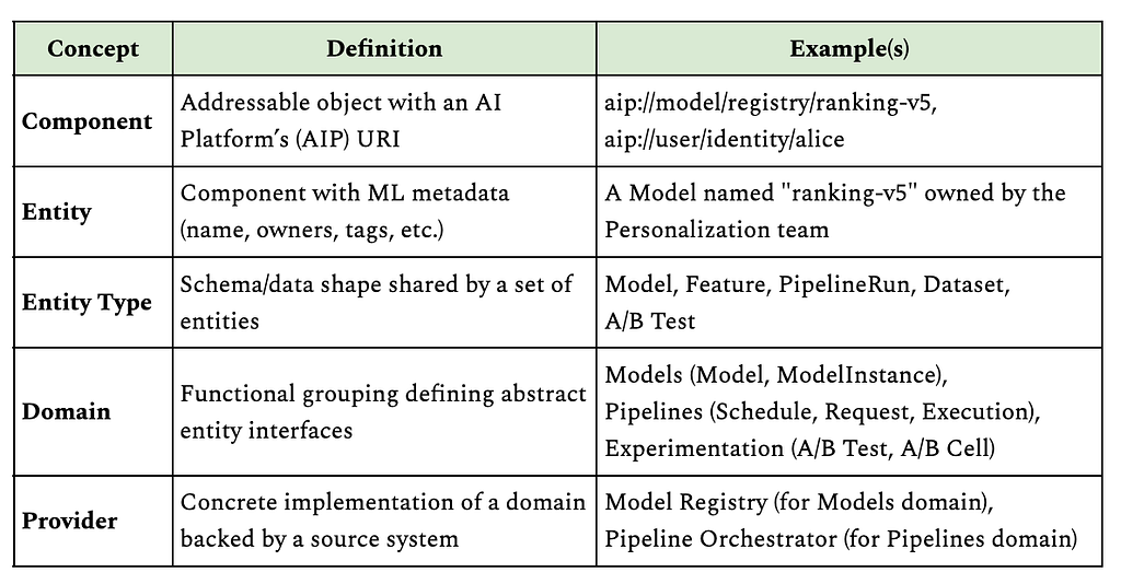
This URI-based addressing scheme is crucial as it allows any service to reference any ML asset with a single string, and MDS can resolve that reference back to rich, connected metadata.

From Events to Entities to Graph
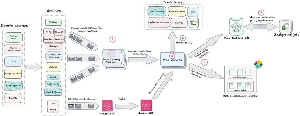
The journey from raw system events to a queryable graph happens in stages. Let’s walk through each with a concrete example: connecting a model to its A/B tests through relationship inference.

1 Event Ingestion

MDS integrates with various source systems via Kafka and AWS SNS/SQS, consuming events in real-time. Source systems emit thin events that include an identifier and an event type.

Example event:

{
"event_type": "model_instance_created",
"instance_id": "ranking-model-v5-20XX0101",
...
}

This design keeps producers simple. Source systems only need to announce that a change occurred, without building complete payloads or understanding downstream requirements.

Each source system has dedicated event handlers in MDS:

  • Pipeline Orchestration: Ingests pipeline execution events, including node definitions, schedules, requests, and job attempts
  • Model Registry: Captures model deployments, configurations, and version updates
  • Feature Store: Tracks feature definitions and their versions
  • Experimentation Platform: Monitors A/B test configurations and allocations
  • Datasets: Tracks ML datasets and their versions
  • Identity Platform: Maintains ownership and team membership information

2 Entity Enrichment

MDS implements a hydration contract for each event type. When an event arrives, MDS:

  1. Validates the event schema
  2. Calls the source system’s API to fetch the complete, current state
  3. Transforms the response into a normalized entity

This design has a crucial property: the order of events doesn’t matter. MDS always fetches the latest facts from the source of truth. This pattern decouples the event stream from state consistency. If the event bus drops a message or delivers it out of order, the next event corrects the state. The event stream becomes a notification of change rather than a log of changes.

This notification of change pattern has a few important tradeoffs. On the plus side, it keeps producers simple, makes us robust to out-of-order or dropped events, and ensures that MDS can always reconcile to the latest state by reading from the source of truth. The tradeoff is that we place additional read load on source systems during hydration and need to be deliberate about rate limiting, caching, and backoff in our enrichment workers so that we don’t overload them.

For our ranking model example, when the model_instance_created event arrives, MDS calls the Model Registry API: GET /api/v1/instances/ranking-model-v5-20XX0101

The registry responds with a full descriptor. Example response (key fields only):

{
"id": "ranking-model-v5-20XX0101",
"pipeline_run_id": "train-weekly-ranking-20XX0101",
"owner_emails": ["[email protected]"],
"labels": [{"key": "team", "value": "personalization"}],
...
}

3 Data Transformation and Normalization

Raw events are heterogeneous and each source system has its own schema and semantics. MDS workers transform these events into a unified entity model with standardized fields.

Without normalization, downstream consumers would need to understand every source system’s schema. Normalization creates a consistent interface, allowing queries and relationships to work across all entity types. Here is an example.

Normalized MDS entity:

{
"id": "aip://model/registry/ranking-model-v5-20XX0101",
"pipeline_run": "aip://pipeline-run/orchestrator/train-weekly-ranking-20XX0101",
"entity_type": "ModelInstance",
"owners": ["aip://user/identity/alice"],
"tags": [{"tag": "team", "value": "personalization"}],
...
}

The normalization process standardizes field names and formats. For example, platform-specific IDs become global AIP URIs, owner_emails becomes owners with resolved user URIs, and labels become tags. Foreign keys like pipeline_run_id are transformed into entity references. However, there’s still no reference to which A/B tests are using this model. The Model Registry doesn’t track experiments, and the Experimentation Platform doesn’t track which pipeline produced a given model. This is where knowledge enrichment becomes critical.

4 Storage and Indexing

Once normalized, entities are persisted to Datomic and immediately indexed in Elasticsearch. This happens synchronously within the event processing flow.

Datomic for Caching and Relationships
Normalized entities are first written to Datomic, which serves as both a local cache and a graph database.

Why Datomic? Datomic serves as both the system of record for MDS and the working dataset for enrichment processes. Its immutable fact model means we can continuously add relationships without losing the original entity state.

What we store:

  • All entity attributes as facts
  • Entity references (foreign keys that may point to entities not yet fully resolved)
  • All relationships as reified edges (added by enrichment processes)
  • Entity lifecycle state (tracking which entities are fully enriched vs awaiting hydration)

This enables:

  • Complex graph traversals: Navigate from a model to its features to their data sources in a single query
  • Entity relationships: Join across multiple domains without N+1 query problems
  • Flexible schema evolution: Easy to add new entity types and attributes as the catalog grows
  • Progressive enrichment: Background jobs efficiently identify and process entities requiring additional hydration, enabling gradual graph completion without reprocessing fully enriched entities

In practice, we use Datomic for relationship-heavy, navigational queries such as:

  • Starting from this model instance, show me all upstream datasets and downstream experiments.
  • Given this feature, list all consuming models and their owning teams.

These queries often span multiple hops in the graph and benefit from Datomic’s immutable fact model and efficient joins across entity relationships.

Elasticsearch for Discovery
Immediately after writing to Datomic, entities are indexed in Elasticsearch to power fast, full-text search across the catalog.

What we index:

  • Primary fields: Entity name, description, entity type, owner names
  • Relationship metadata: Names of related entities (e.g., a model’s features, pipelines, A/B tests) stored in the related field
  • Tags: Domain-specific metadata stored as key-value pairs (e.g., team::personalization, env::production, model.state::released)

Index structure:

  • Single entities index: All entity types (models, features, pipelines, etc.) are indexed in one unified index, differentiated by the entityType field
  • Separate owners index: Dedicated index for users and groups to enable cross-entity owner searches
  • Relevance boosting: Exact name matches score higher than other relevant matches

This enables:

  • Multi-field text search across entity names, descriptions, tags, and related metadata
  • Relevance ranking with boosting (exact name matches score significantly higher)
  • Complex filtering by entity type, ownership, tags, and domain-specific attributes (stored as tags)
  • Fuzzy matching to handle typos and partial queries

Elasticsearch powers the entry point into the system: users typically start with a free-text search in the AIP Portal (for a model name, a team, or a domain term), and then switch to graph navigation once they land on an entity page. Indexing happens in near real-time as part of the ingestion and enrichment workflows, so changes are usually visible in the Portal with a short delay that is acceptable for interactive use.

5 Knowledge Enrichment and Graph Formation

Once entity metadata is persisted in Datomic, scheduled background processes take over to discover and materialize relationships. These enrichment jobs run periodically, scanning for uncached or partially resolved entities (entities that exist only as references without full metadata).

The enrichment workflow:

  • Identify candidates: Find entities marked as uncached or with unresolved references
  • Hydrate relationships: Query source-of-truth systems to fetch related entity details
  • Materialize edges: Write discovered relationships back to Datomic
  • Re-index: Trigger Elasticsearch indexing for updated entities
  • Mark as enriched: Update entity status to prevent redundant processing

This asynchronous approach allows MDS to handle the computational cost of graph formation without blocking real-time event ingestion. It also enables retry logic and gradual enrichment as new entities become available.

Because enrichment is asynchronous, newly discovered relationships may appear with a short delay after the underlying entities are created (typically minutes rather than seconds). We track when each entity was last enriched and surface this timestamp in the AIP Portal, so practitioners can reason about staleness and know when it’s safe to rely on a particular relationship for debugging or impact analysis.

Why enrich? Source systems are purpose-built and don’t know about entities in other domains. Enrichment discovers and materializes cross-system relationships that enable powerful lineage and impact queries.

Example: Connecting Models to A/B Tests

When MDS processes a new model instance, background enrichment jobs discover relationships through multi-hop inference:

Step 1: Direct link to pipeline

The model references a pipeline_run_id. An enrichment job hydrates the pipeline and discovers its A/B test associations: GET /api/v1/pipeline-runs/train-weekly-ranking-20XX0101

Response:

{
"run_id": "train-weekly-ranking-20XX0101", "pipeline": "weekly-ranking-trainer",
"ab_test_cells": [
{"test_id": "12345","cell_number": 2,"cell_name": "treatment_ranking_v5"}
]
...
}

Step 2: Discover A/B test context
The enrichment job discovers the pipeline ran for A/B test cell #2 and queries the Experimentation Platform for test details: GET /api/v1/tests/12345

{
"test_id": "12345",
"name": "Ranking Model v5 vs v4",
"status": "ACTIVE",
"cells": [{"cell_number": 1, "name": "control_ranking_v4"}],
...
}

Step 3: Infer transitive relationships
The enrichment job now has the complete chain:

  • Model Instance was produced by Pipeline Run
  • Pipeline Run was executed for A/B Test Cell #2
  • The A/B Test Cell #2 belongs to A/B Test “Ranking Model v5 vs v4”
  • Model Instance now gets associated with this A/B Test

The job writes the inferred relationship back to Datomic and triggers re-indexing, and materializes these edges in the graph. MDS doesn’t just store what it’s told; it derives new knowledge by walking the graph in the background.

Why this matters: Without MDS, answering “Which A/B tests are using this model?” requires:

  1. Looking up the model in the Model Registry
  2. Finding which pipeline produced it
  3. Checking the Pipeline Orchestrator for A/B test tags
  4. Querying the Experimentation Platform for test details

With the model lifecycle graph, it’s a single query:

query {
model(id: "aip://model/registry/ranking-model-v5-20XX0101") {
name
owners { name }
currentInstance {
version
pipeline {
name
owners { name }
}
features {
edges {
node {
name
data { edges { node { name } } }
}
}
}
associatedAbTests {
name
cells { number name }
}
}
}
}

The reverse query also works: “What models are being tested in experiment 12345?”

Enabling Exploration, Not Just Search
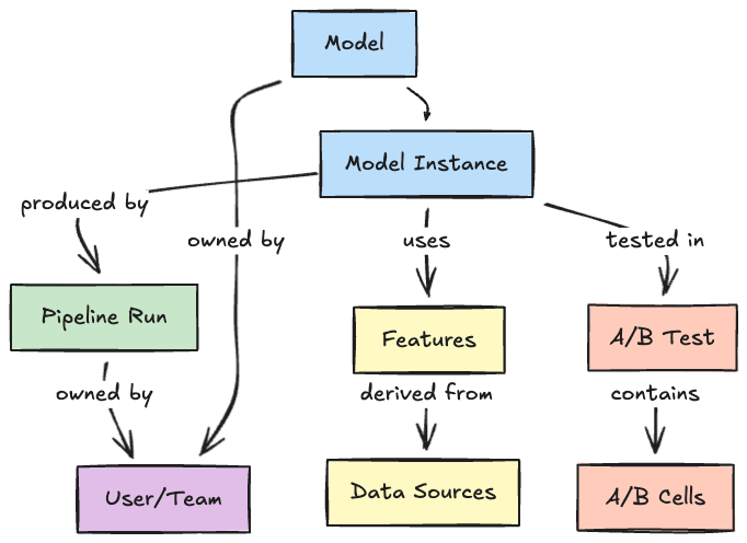
With the Model Lifecycle Graph in place, we shift from entity search to entity exploration. Discovery isn’t just about finding a model; It’s about traversing relationships:

  • Start with a model, explore its features
  • From features, navigate to the core data driving them
  • From the data, trace back to the pipelines generating it
  • From pipelines, see which teams own and depend on them
  • From experiments, understand which models are being tested

For example, imagine an engineer investigating a degraded engagement metric for a personalization model. They might:

  1. Start with the model instance powering the affected recommendations in the AIP Portal.
  2. Inspect the model’s features and follow a suspicious feature to its upstream dataset.
  3. From the dataset page, see that its pipeline recently had failed runs and identify the owning team.
  4. Confirm which A/B tests are currently running this model instance to understand which members and surfaces are impacted.

Before MDS and the Model Lifecycle Graph, this required manual checks across multiple tools (model registry, pipeline orchestrator, experiment platform). Now it’s a contiguous journey in a single interface.

This graph-based exploration answers questions that were previously impossible:

  • Lineage queries: What is the complete lineage of this model, from training data to production experiments?
  • Impact analysis: Which models will be affected if I change this feature?
  • Usage discovery: Which A/B tests are using this model?
  • Dependency mapping: What data sources does my pipeline transitively depend on?
  • Deprecation planning: Which entities are no longer being used and can be retired?

Every entity has deep context: its creation time, ownership, update history, and most importantly, its relationships to other entities.

The Model Lifecycle Graph is surfaced to practitioners through the AIP Portal, a unified interface that provides full-text search across all entity types, detailed entity pages with navigable relationships, and personalized views for teams and individuals.

A typical interaction in the AIP Portal looks like:

  • Search: Type a model, feature, dataset, or team name into the single search box backed by Elasticsearch.
  • Inspect: Land on an entity page that shows key metadata (description, owners, domains, tags) alongside a relationships panel.
  • Explore: Click through to related entities (upstream datasets, downstream experiments, and sibling model versions) to navigate the Model Lifecycle Graph without leaving the portal.

When new entity types are introduced into MDS, the portal automatically provides baseline search, entity pages, and relationship navigation, and we can then layer on domain-specific visualizations (such as model deployment history or dataset version timelines) over time.

The Road Ahead: Open Challenges

Building the ML lifecycle graph is an ongoing journey. Significant challenges remain, and these represent the future opportunities for us:

  • Tool Proliferation: As new ML tools emerge, we need robust integration patterns that scale. How do we design plugin architectures that make adding new sources seamless? If we don’t keep up with new tools, practitioners will be forced back into fragmented views, and the Model Lifecycle Graph will lose coverage and trust.
  • Domain-Specific Visualizations: Different entity types require distinct visualization experiences. Model pages should display deployment history, A/B test associations, and performance metrics. Feature pages should highlight data lineage and consuming models. Pipeline pages must show execution history, dependencies, and schedules. Dataset pages require versioning timelines and downstream consumers. How do we design a flexible UI framework that allows each entity type to have its own tailored experience while maintaining consistent navigation and interaction patterns across the portal? Without rich, domain-specific experiences, the portal risks becoming a generic catalog rather than a tool that ML practitioners rely on in their daily workflows.
  • Metadata Quality: Today, MDS ensures data consistency through source-of-truth hydration and schema validation at ingestion. Background enrichment jobs continuously infer relationships and materialize entities from source systems. However, challenges remain in ensuring completeness and timeliness at scale. When source systems fail to emit events, when ownership information becomes stale, or when entities lack descriptions and contextual metadata, the graph’s utility degrades. How do we build automated validation and enrichment systems to detect metadata anomalies, suggest missing relationships, and maintain quality benchmarks across millions of entities? Poor or stale metadata erodes practitioner trust: if the graph is incomplete or incorrect, teams will revert to ad hoc knowledge and one-off integrations rather than using MDS as their source of truth.
  • Advanced Relationship Inference: Beyond explicit relationships declared in source systems, how do we infer implicit connections? Can we detect that two models serve similar purposes based on shared features? Can we recommend features based on usage patterns from similar pipelines? We are in the early stages of exploring these ideas. Done well, they would turn MDS from a passive catalog into an active recommendation engine for ML assets, accelerating reuse and reducing duplicate work across domains.

Acknowledgments

This work represents the collective effort of stunning colleagues across the AI Platform organization: Emma Carney, Megan Ren, Nadeem Ahmad, Pat Olenik, Prateek Agarwal, Tigran Hakobyan, Yinglao Liu


Democratizing Machine Learning at Netflix: Building the Model Lifecycle Graph was originally published in Netflix TechBlog on Medium, where people are continuing the conversation by highlighting and responding to this story.
Physics on AWS: Optimizing wind turbine performance using OpenFAST in a digital twin

Post Syndicated from Marco Masciola original https://aws.amazon.com/blogs/architecture/physics-on-aws-optimizing-wind-turbine-performance-using-openfast-in-a-digital-twin/

Wind energy plays a crucial role in global decarbonization efforts by generating emission-free power from an abundant resource. In 2022, wind energy produced 2100 terawatt-hours (TWh) globally, or over 7% of global electricity, with expectations to reach 7400 TWh by 2030.

Despite its potential, several challenges must be addressed to help meet grid decarbonization targets. As wind energy adoption grows, issues like gearbox fatigue and leading-edge erosion need to be resolved to ensure a predictable supply of energy. For example, in the United States, wind turbines underperform by as much as 10% after 11 years of operation, despite expectations for the machine to operate at full potential for 25 years.

This blog reveals a digital twin architecture using the National Renewable Energy Laboratory’s (NREL) OpenFAST, an open-source multi-physics wind turbine simulation tool, to characterize operational anomalies and continuously improve wind farm performance. This approach can be used to support an overall maintenance strategy to optimize performance and profitability while reducing risk.

While a digital twin can take many forms, this architecture represents it with a physical wind turbine connected to the cloud using IoT devices to monitor performance and augmented knowledge using on-demand simulations. The insight gained from simulations can update the physical asset control system in near real-time to balance operational performance.

Why build this?

This digital twin can catch reliability assessment discrepancies by benchmarking real-world time series with simulations. Aeroelastic simulators like OpenFAST define operational envelopes as part of wind turbine design and certification in accordance with IEC 61400-1 and 61400-3. However, subtle, unanticipated changes in environmental conditions not accounted for in the initial design certification, such as higher turbulence intensity, accelerate degradation.

This architecture can be used to validate if a controller change can limit gradual performance damage before the controller changes are deployed by using the same simulation software for wind turbine design. This example scenario, one that operators currently struggle with, is threaded in the next section.

Digital twin architecture

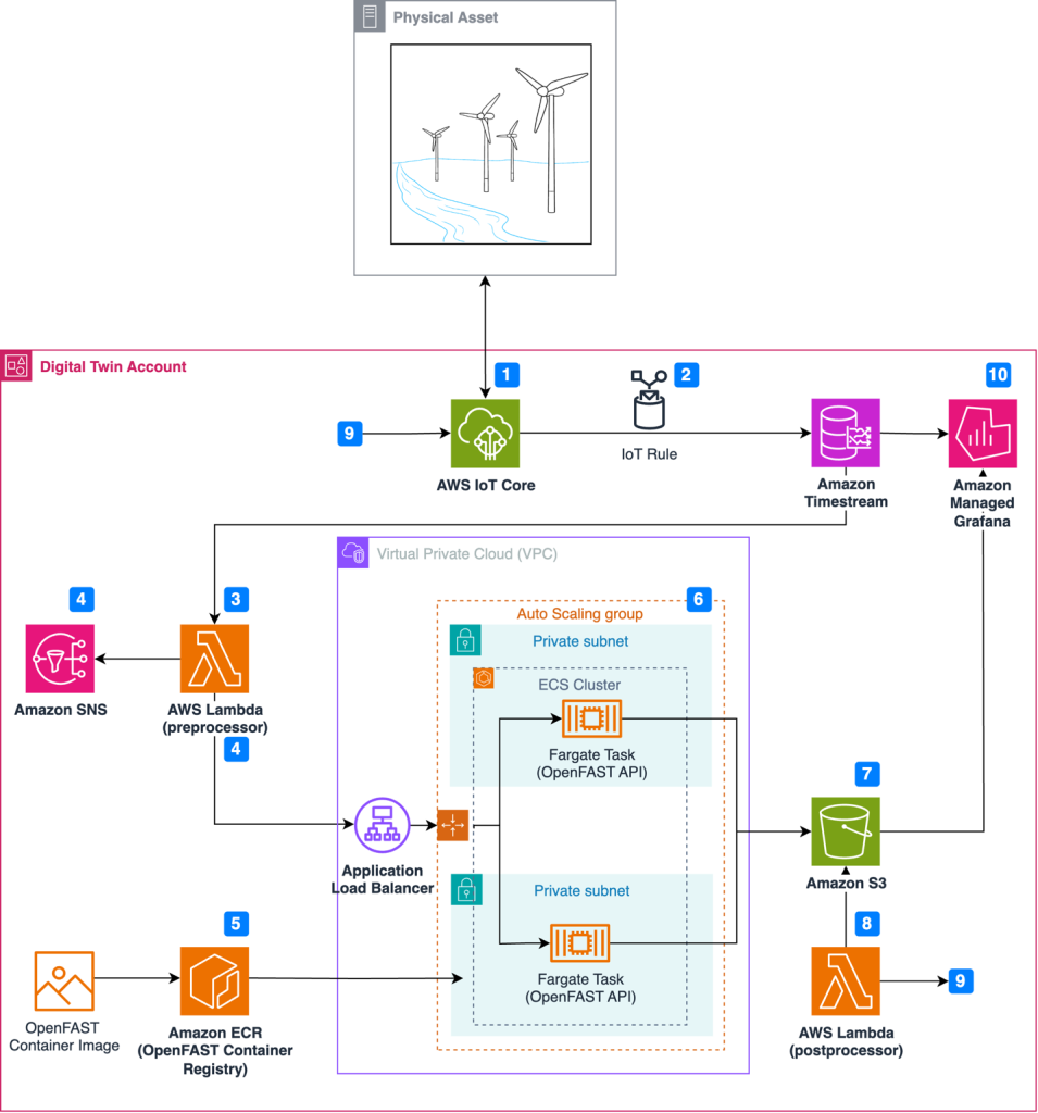
Figure 1 illustrates the event-driven architecture in which resources launch on-demand simulations as anomalies occur.

Architecture for wind turbine digital twin solution

Figure 1. Architecture for wind turbine digital twin solution

Simulation and real-world results can feed into a calculation engine to update the wind turbine controller software and improve operational performance through this workflow:

  1. Wind turbine sensors are connected to the AWS cloud using AWS IoT Core.
  2. An IoT rule forwards sensor data to Amazon Timestream, a purpose-built time series database.
  3. A scheduled AWS Lambda function queries Timestream to detect anomalies in time-series data.
  4. Upon anomaly detection, Amazon Simple Notification Service (Amazon SNS) publishes notifications and OpenFAST simulation input files are prepared in the Lambda preprocessor.
  5. Simulations are executed on demand, where the latest OpenFAST simulation is pulled from Amazon Elastic Container Registry (Amazon ECR).
  6. Simulations are dispatched through RESTful API and run using AWS Fargate.
  7. Simulation results are uploaded to Amazon Simple Storage Service (Amazon S3).
  8. Simulation time-series data is processed using AWS Lambda, where a decision is made to update the controller software based on the anomaly.
  9. The Lambda post-processer initiates a wind turbine controller software update, which is communicated to the wind turbine through AWS IoT Core.
  10. Results are visualized in Amazon Managed Grafana.

An example of an anomaly in step 3 is a controller overspeed alarm. Simple rule-based anomaly detection can be used to detect exceedance thresholds. You can also incorporate more sophisticated forms of anomaly detection using machine learning through Amazon SageMaker. The workflow above preserves four elements to create a digital twin. We will explore these four elements in the next section:

Event-driven architecture

Event-driven architectures enable decoupled systems and asynchronous communications between services. An event-driven workflow is initiated automatically as events occur. An event might be an active alarm or an OpenFAST output file uploaded to Amazon S3. This means that the number of actively monitored wind turbines can scale from one to 100 (or more) without allocating new resources.

AWS Lambda provides instant scaling to increase the number of OpenFAST simulations available for processing. Additionally, Fargate removes the need to provision or manage the underlying OpenFAST compute instances. Leveraging serverless compute services removes the need to manage underlying infrastructure, provides demand-based scaling, and reduces costs compared to statically provisioned infrastructure.

In practice, event-driven architecture provides teams with flexibility to automatically prepare input files, dispatch simulations, and post-process results without manually provisioning resources.

Containerization

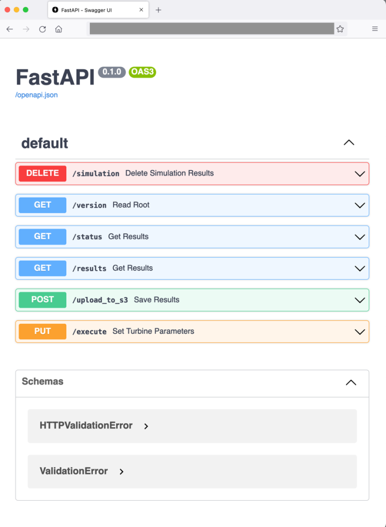
Containerization is a process to deploy an application with libraries needed for execution. Docker creates a container image that bundles the OpenFAST executable. FastAPI is also included in the OpenFAST container so that simulations can be dispatched through a web RESTful API, as demonstrated in Figure 2. Note that OpenFAST and FastAPI are independent projects. The RESTful API for OpenFAST is provisioned with commands to:

  • Run the simulation with initial conditions (PUT: /execute)
  • Upload simulation results to Amazon S3 (POST: /upload_to_s3)
  • Provide simulation status (GET: /status)
  • Delete simulation results (DELETE: /simulation)

This setup enables engineering teams to pull an OpenFAST simulation version aligned with physical wind turbines in operation without manual configuration.

Web frontend showing the RESTfulAPI commands available for dispatching OpenFAST simulations

Figure 2. Web frontend showing the RESTfulAPI commands available for dispatching OpenFAST simulations

Load balancing and auto scaling

The architecture uses Amazon EC2 Auto Scaling and an ALB to manage fluctuating processing demands and enable concurrent OpenFAST simulations. EC2 Auto Scaling dynamically scales the number of OpenFAST containers based on the volume of simulation requests and offers cost savings to avoid idle resources. Paired with an ALB, this setup evenly distributes simulation requests across OpenFAST containers, ensuring desired performance levels and high availability.

Data visualization

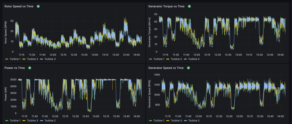
Amazon Timestream collects and archives real-time metrics from physical wind turbines. Timestream can store any metric from the physical asset collected through IoT Core, including rotor speed, generator power, generator speed, generator torque, or wind turbine control system alarms, as shown in Figure 3. One distinctive Timestream feature is scheduled queries that can regularly perform automated tasks like measuring 10-minute average wind speeds or tracking down units with controller alarms.

This provides operations teams the ability to view granular insights in real time or query historical data using SQL. Amazon Managed Grafana is also connected to OpenFAST results stored in Amazon S3 to compare simulation results with real-world operational data and view the response of simulated components. Engineering teams benefit from Amazon Managed Grafana because it provides a window into how the simulation responds to controller changes. Engineers can then verify whether the physical machine responds in the expected manner.

Example Amazon Managed Grafana dashboard

Figure 3. Example Amazon Managed Grafana dashboard

Conclusion

The AWS Cloud offers services and infrastructure to provide organization resources to process data and build digital twins. Organizations can leverage open-source models to improve operational performance and physics-based simulations to improve accuracy. By integrating technology paradigms such as event-drive architectures, wind turbine operators can make data-driven decisions in real time. Organizations can create virtual replicas of physical wind turbines to diagnose the source of alarms and adopt strategies to limit excessive wear before permanent damage occurs.

Top Architecture Blog Posts of 2023

Post Syndicated from Andrea Courtright original https://aws.amazon.com/blogs/architecture/top-architecture-blog-posts-of-2023/

2023 was a rollercoaster year in tech, and we at the AWS Architecture Blog feel so fortunate to have shared in the excitement. As we move into 2024 and all of the new technologies we could see, we want to take a moment to highlight the brightest stars from 2023.

As always, thanks to our readers and to the many talented and hardworking Solutions Architects and other contributors to our blog.

I give you our 2023 cream of the crop!

#10: Build a serverless retail solution for endless aisle on AWS

In this post, Sandeep and Shashank help retailers and their customers alike in this guided approach to finding inventory that doesn’t live on shelves.

Building endless aisle architecture for order processing

Figure 1. Building endless aisle architecture for order processing

Check it out!

#9: Optimizing data with automated intelligent document processing solutions

Who else dreads wading through large amounts of data in multiple formats? Just me? I didn’t think so. Using Amazon AI/ML and content-reading services, Deependra, Anirudha, Bhajandeep, and Senaka have created a solution that is scalable and cost-effective to help you extract the data you need and store it in a format that works for you.

AI-based intelligent document processing engine

Figure 2: AI-based intelligent document processing engine

Check it out!

#8: Disaster Recovery Solutions with AWS managed services, Part 3: Multi-Site Active/Passive

Disaster recovery posts are always popular, and this post by Brent and Dhruv is no exception. Their creative approach in part 3 of this series is most helpful for customers who have business-critical workloads with higher availability requirements.

Warm standby with managed services

Figure 3. Warm standby with managed services

Check it out!

#7: Simulating Kubernetes-workload AZ failures with AWS Fault Injection Simulator

Continuing with the theme of “when bad things happen,” we have Siva, Elamaran, and Re’s post about preparing for workload failures. If resiliency is a concern (and it really should be), the secret is test, test, TEST.

Architecture flow for Microservices to simulate a realistic failure scenario

Figure 4. Architecture flow for Microservices to simulate a realistic failure scenario

Check it out!

#6: Let’s Architect! Designing event-driven architectures

Luca, Laura, Vittorio, and Zamira weren’t content with their four top-10 spots last year – they’re back with some things you definitely need to know about event-driven architectures.

Let's Architect

Figure 5. Let’s Architect artwork

Check it out!

#5: Use a reusable ETL framework in your AWS lake house architecture

As your lake house increases in size and complexity, you could find yourself facing maintenance challenges, and Ashutosh and Prantik have a solution: frameworks! The reusable ETL template with AWS Glue templates might just save you a headache or three.

Reusable ETL framework architecture

Figure 6. Reusable ETL framework architecture

Check it out!

#4: Invoking asynchronous external APIs with AWS Step Functions

It’s possible that AWS’ menagerie of services doesn’t have everything you need to run your organization. (Possible, but not likely; we have a lot of amazing services.) If you are using third-party APIs, then Jorge, Hossam, and Shirisha’s architecture can help you maintain a secure, reliable, and cost-effective relationship among all involved.

Invoking Asynchronous External APIs architecture

Figure 7. Invoking Asynchronous External APIs architecture

Check it out!

#3: Announcing updates to the AWS Well-Architected Framework

The Well-Architected Framework continues to help AWS customers evaluate their architectures against its six pillars. They are constantly striving for improvement, and Haleh’s diligence in keeping us up to date has not gone unnoticed. Thank you, Haleh!

Well-Architected logo

Figure 8. Well-Architected logo

Check it out!

#2: Let’s Architect! Designing architectures for multi-tenancy

The practically award-winning Let’s Architect! series strikes again! This time, Luca, Laura, Vittorio, and Zamira were joined by Federica to discuss multi-tenancy and why that concept is so crucial for SaaS providers.

Let's Architect

Figure 9. Let’s Architect

Check it out!

And finally…

#1: Understand resiliency patterns and trade-offs to architect efficiently in the cloud

Haresh, Lewis, and Bonnie revamped this 2022 post into a masterpiece that completely stole our readers’ hearts and is among the top posts we’ve ever made!

Resilience patterns and trade-offs

Figure 10. Resilience patterns and trade-offs

Check it out!

Bonus! Three older special mentions

These three posts were published before 2023, but we think they deserve another round of applause because you, our readers, keep coming back to them.

Thanks again to everyone for their contributions during a wild year. We hope you’re looking forward to the rest of 2024 as much as we are!

Let’s Architect! Multi-tenant SaaS architectures

Post Syndicated from Luca Mezzalira original https://aws.amazon.com/blogs/architecture/lets-architect-multi-tenant-saas-architectures/

In a multi-tenant architecture multiple instances of an application run on a shared infrastructure. With this type of approach, each tenant is isolated from others, typically through logical separation, while utilizing a shared infrastructure. This allows multiple tenants to use the same application and maintain their data security, privacy, and customization requirements.

Understanding architectural patterns for multi-tenancy has become crucial for architects and developers aiming to deliver scalable, secure, and cost-effective solutions. Isolating tenant data is a fundamental responsibility for Software as a Service (SaaS) providers. In this edition of Let’s Architect!, we talk about comprehensive exploration of multi-tenant architectures, covering various aspects, such as SaaS microservices, SaaS serverless, SaaS EKS, and an insightful whitepaper.

SaaS microservices deep dive: Simplifying multi-tenant development

In this session, Michael Beardsley, Principal Solutions Architect at AWS, takes a deep dive into the realm of multi-tenant microservices, exploring various patterns and strategies that enable the seamless implementation of multi-tenant microservices, all while ensuring that additional complexity is not imposed upon the SaaS builders. He shares practical patterns to simplify the development process by addressing crucial aspect, such as authorization, data access, tenant isolation, metrics, billing, logging, and a plethora of other considerations; this is irrespective of the chosen compute platform (like Amazon Elastic Container Service, Amazon Elastic Kubernetes Service [Amazon EKS], or AWS Lambda) or database solution.

There is another session available that highlights specific techniques and architecture strategies that can directly impact the success of a SaaS business. If you’re interested in learning more about optimizing multi-tenant SaaS architecture, this session is a great opportunity.

Take me to this video!

SaaS multi-tenant microservices

SaaS multi-tenant microservices

Building a Multi-Tenant SaaS Solution Using AWS Serverless Services

In this AWS Partner Network (APN) Blog post, you will explore a reference solution that presents a comprehensive perspective on a functional multi-tenant serverless SaaS environment. This solution effectively showcases various essential components required to construct a multi-tenant SaaS solution using serverless services, including onboarding processes, tenant isolation mechanisms, data partitioning techniques, a tenant deployment pipeline, and robust observability measures.

By delving into these aspects, you can gain valuable insights into the architecture and design considerations involved in creating a successful multi-tenant SaaS solution.

Take me to this AWS APN blogpost!

Tenant registration flow

Tenant registration flow

Amazon EKS SaaS deep dive: A multi-tenant EKS SaaS solution

In this re:Invent 2021 presentation, Tod Golding, Principal Partner Solutions Architect, chats about a SaaS reference solution that addresses fundamental multi-tenant considerations, examining its approach to core SaaS topics, including tenant isolation, identity, onboarding, tenant administration, and data partitioning. The goal is to explore an Amazon EKS SaaS architecture through the lens of working code and highlight the key architectural strategies that were used in this reference environment.

There is also valuable information available on Github regarding EKS multi-tenancy. Exploring the Github repositories related to EKS multi-tenancy can provide further insights, resources, and practical examples for implementing multi-tenant architectures on EKS. This presentation is an engaging way to dive deeper into this topic and gain a more comprehensive understanding of best practices and real-world implementations.

Take me to this video!

Tenant deployment model

Tenant deployment model

Saas Storage Strategies

Storage represents a challenging aspect of building and delivering multi-tenant software solutions. There are different strategies that can be used to partition tenant data, each with a unique set of trade-offs for implementing separation between tenants. This whitepaper covers different storage models for multi-tenancy; in particular, you can learn about the:

  • Silo model (data from the tenant is fully isolated)
  • Pool model (all the tenants use the same database and table)
  • Bridge model (single database but a different table for each tenant)

For each of these models, the whitepaper describes in detail how they can be implemented, as well as the different trade-offs in terms of isolation and agility. You can also discover how these tenancy models can be implemented specifically on databases, such as Amazon DynamoDB and Amazon Relational Database Service, thus covering both NoSQL and SQL scenarios.

Take me to this whitepaper!

Partitioning model tradeoffs

Partitioning model tradeoffs

See you next time!

Thanks for joining our conversation on multi-tenant SaaS architectures! Next time, we’ll talk about open-source technologies.

To find all the blogs from this series, you can check out the Let’s Architect! list of content on the AWS Architecture Blog.

Let’s Architect! Designing microservices architectures

Post Syndicated from Luca Mezzalira original https://aws.amazon.com/blogs/architecture/lets-architect-designing-microservices-architectures/

In 2022, we published Let’s Architect! Architecting microservices with containers. We covered integrations patterns and some approaches for implementing microservices using containers. In this Let’s Architect! post, we want to drill down into microservices only, by focusing on the main challenges that software architects and engineers face while working on large distributed systems structured as a set of independent services.

There are many considerations to cover in detail within a broad topic like microservices. We should reflect on the organizational structure, automation pipelines, multi-account strategy, testing, communication, and many other areas. With this post we dive deep into the topic by analyzing the options for discoverability and connectivity available through Amazon VPC Lattice; then, we focus on architectural patterns for communication, mainly on asynchronous communication, as it fits very well into the paradigm. Finally, we explore how to work with serverless microservices and analyze a case study from Amazon, coming directly from the Amazon Builder’s Library.

AWS Container Day featuring Kubernetes

Modern applications are often built using a microservice distributed approach, which involves dividing the application into smaller, specialized services. Each of these services implement their own subset of functionalities or business logic. To facilitate communication between these services, it is essential to have a method to authorize, route, and monitor network traffic. It is also important, in case of issues, to have the ability of identifying the root cause of an issue, whether it originates at the application, service, or network level.

Amazon VPC Lattice can offer a consistent way to connect, secure, and monitor communication between instances, containers, and serverless functions. With Amazon VPC Lattice, you can define policies for traffic management, network access, advanced routing, implement discoverability, and, at the same time, monitor how the traffic is flowing inside complex applications in near real time.

Take me to this video!

Amazon VPC Lattice service gives you a consistent way to connect, secure, and monitor communication between your services

Amazon VPC Lattice service gives you a consistent way to connect, secure, and monitor communication between your services

Application integration patterns for microservices

Loosely coupled integration can help you design independent systems that can be developed and operated individually, plus increase the availability and reliability of the overall system landscape—particularly by using asynchronous communication. While there are many approaches for integration and conversation scenarios, it’s not always clear which approach is best for a given situation.

Join this re:Invent 2022 session to learn about foundational patterns for integration and conversation scenarios with an emphasis on loose coupling and asynchronous communication. Explore real-world use cases architected with cloud-native and serverless services, and receive guidance on choosing integration technology.

Take me to this re:Invent 2022 video!

Loosely coupled integration can help you design independent systems that can be developed and operated individually and can also increase the availability and reliability of the overall system

Loosely coupled integration can help you design independent systems that can be developed and operated individually and can also increase the availability and reliability of the overall system

Design patterns for success in serverless microservices

Software engineers love patterns—proven approaches to well-known problems that make software development easier and set our projects up for success. In complex, distributed systems, such as microservices, patterns like CQRS and Event Sourcing help decouple and scale systems.

The first part of the video is all about introducing architectural patterns and their applications, while the second part contains a set of demos and examples from the AWS console.
In this session, we examine at some typical patterns for building robust and performant serverless microservices, and how data access patterns can drive polyglot persistence.

Take me to this AWS Summit video!

With Event Sourcing data is stored as a series of events, instead of direct updates to data stores. Microservices replay events from an event store to compute the appropriate state of their own data stores

With event sourcing data is stored as a series of events, instead of direct updates to data stores; microservices replay events from an event store to compute the appropriate state of their own data stores

Avoiding overload in distributed systems by putting the smaller service in control

If we don’t pay attention to the relative scale of a service and its clients, distributed systems with microservices can be at risk of overload. A common architecture pattern adopted by many AWS services consists of splitting the system in a control plane and a data plane.

This article drills down into this scenario to understand what could happen if the data plane fleet exceeds the scale of the control plane fleet by a factor of 100 or more. This can happen in a microservices-based architecture when service X recovers from an outage and starts sending a large amount of request to service Y. Without careful fine-tuning, this shift in behavior can overwhelm the smaller callee. With this resource, we want to share some mental models and design strategies that are beneficial for distributed systems and teams working on microservices architectures.

Take me to the Amazon Builders’ Library!

To stay up to date on the data plane’s operational state, the control plane can poll an Amazon S3 bucket into which data plane servers periodically write that information

To stay updated on the data plane’s operational state, the control plane can poll an Amazon S3 bucket into which data plane servers periodically write that information

See you next time!

Thanks for stopping by! Join us in two weeks when we’ll discuss multi-tenancy and patterns for SaaS on AWS.

To find all the blogs from this series, you can check out the Let’s Architect! list of content on the AWS Architecture Blog.

Let’s Architect! Designing serverless solutions

Post Syndicated from Luca Mezzalira original https://aws.amazon.com/blogs/architecture/lets-architect-designing-serverless-solutions/

During his re:Invent 2022 keynote, Werner Vogels, AWS Vice President and Chief Technology Officer, emphasized the asynchronous nature of our world and the challenges associated with incorporating asynchronicity into our architectures. AWS serverless services can help users concentrate on the asynchronous aspects of their workloads, easing the execution of event-driven architectures and enabling the adoption of effective integration patterns for communication both within and beyond a bounded context.

In this edition of Let’s Architect!, we offer an in-depth exploration of the architecture of serverless AWS services, such as AWS Lambda. We also present a new workshop centered on design patterns employing serverless AWS services, which ultimately delivers valuable insights on implementing event-driven architectures within systems.

A closer look at AWS Lambda

This video is the perfect companion for those seeking to learn and master a Lambda architecture, empowering you to effectively leverage its capabilities in your workloads.

With the knowledge gained from this video, you will be well-equipped to design your functions’ code in a highly optimized manner, ensuring efficient performance and resource utilization. Furthermore, a comprehensive understanding of Lambda functions can help identify and apply the most suitable approach to cloud workloads, resulting in an agile and robust cloud infrastructure that meets a project’s unique requirements.

Take me to this video!

Discover how AWS Lambda functions work under the hood

Discover how AWS Lambda functions work under the hood

Implementing an event-driven serverless story generation application with ChatGPT and DALL-E

This example of an event-driven serverless architecture showcases the power of leveraging AWS services and AI technologies to develop innovative solutions. Built upon a foundation of serverless services, including Amazon EventBridge, Amazon DynamoDB, Lambda, Amazon Simple Storage Service, and managed artificial intelligence (AI ) services like Amazon Polly, this architecture demonstrates the seamless capacity to create daily stories with a scheduled launch. By utilizing EventBridge scheduler, an Lambda function is initiated every night to generate new content. The integration of AI services, like ChatGPT and DALL-E, further elevates the solution, as their compatibility with the serverless model enables efficient and dynamic content creation. This case serves as a testament to the potential of combining event-driven serverless architectures, with cutting-edge AI technologies for inventive and impactful applications.

Take me to this Compute Blog post!

How to build an event-driven architecture with serverless AWS services integrating ChatGPT and DALL-E

How to build an event-driven architecture with serverless AWS services integrating ChatGPT and DALL-E

AWS Workshop Studio: Serverless Patterns

The AWS Serverless Patterns workshop offers a comprehensive learning experience to enhance your understanding of architectural patterns applicable to serverless projects. Throughout the workshop, participants will delve into various patterns, such as synchronous and asynchronous implementations, tailored to meet the demands of modern serverless applications. This hands-on approach ensures a production-ready understanding, encompassing crucial topics like testing serverless workloads, establishing automation pipelines, and more. Take this workshop to elevate your serverless architecture knowledge!

Take me to the serverless workshop!

The high-level architecture of the workshops modules

The high-level architecture of the workshops modules

Building Serverlesspresso: Creating event-driven architectures

Serverlesspresso is an event-driven, serverless workload that uses EventBridge and AWS Step Functions to coordinate events across microservices and support thousands of orders per day. This comprehensive session delves into design considerations, development processes, and valuable lessons learned from creating a production-ready solution. Discover practical patterns and extensibility options that contribute to a robust, scalable, and cost-effective application. Gain insights into combining EventBridge and Step Functions to address complex architectural challenges in larger applications.

Take me to this video!

How to leverage AWS Step Functions for orchestrating your workflows

How to leverage AWS Step Functions for orchestrating your workflows

See you next time!

Thanks for joining our conversation on serverless solutions! We’ll see you next time when we talk about AWS microservices.

Can’t get enough of the Let’s Architect! series? Visit the Let’s Architect! page of the AWS Architecture Blog!

Let’s Architect! Designing event-driven architectures

Post Syndicated from Luca Mezzalira original https://aws.amazon.com/blogs/architecture/lets-architect-designing-event-driven-architectures/

During the design of distributed systems, we have to identify a communication strategy to exchange information between different services while keeping the evolutionary nature of the architecture in mind. Event-driven architectures are based on events (facts that happened in a system), which are asynchronously exchanged to implement communication across different services while having a high degree of decoupling. This paradigm also allows us to run code in response to events, with benefits like cost optimization and sustainability for the entire infrastructure.

In this edition of Let’s Architect!, we share architectural resources to introduce event-driven architectures, how to build them on AWS, and how to approach the design phase.

AWS re:Invent 2022 – Keynote with Dr. Werner Vogels

re:Invent 2022 may be finished, but the keynote given by Amazon’s Chief Technology Officer, Dr. Werner Vogels, will not be forgotten. Vogels not only covered the announcements of new services but also event-driven architecture foundations in conjunction with customers’ stories on how this architecture helped to improve their systems.

Take me to this re:Invent 2022 video!

Dr. Werner Vogels presenting an example of architecture where Amazon EventBridge is used as event bus

Dr. Werner Vogels presenting an example of architecture where Amazon EventBridge is used as event bus

Benefits of migrating to event-driven architecture

In this blog post, we enumerate clearly and concisely the benefits of event-driven architectures, such as scalability, fault tolerance, and developer velocity. This is a great post to start your journey into the event-driven architecture style, as it explains the difference from request-response architecture.

Take me to this Compute Blog post!

Two common options when building applications are request-response and event-driven architecture

Two common options when building applications are request-response and event-driven architectures

Building next-gen applications with event-driven architectures

When we build distributed systems or migrate from a monolithic to a microservices architecture, we need to identify a communication strategy to integrate the different services. Teams who are building microservices often find that integration with other applications and external services can make their workloads tightly coupled.

In this re:Invent 2022 video, you learn how to use event-driven architectures to decouple and decentralize application components through asynchronous communication. The video introduces the differences between synchronous and asynchronous communications before drilling down into some key concepts for designing and building event-driven architectures on AWS.

Take me to this re:Invent 2022 video!

How to use choreography to exchange information across services plus implement orchestration for managing operations within the service boundaries

How to use choreography to exchange information across services plus implement orchestration for managing operations within the service boundaries

Designing events

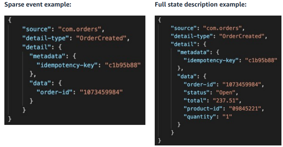
When starting on the journey to event-driven architectures, a common challenge is how to design events: “how much data should an event contain?” is a typical first question we encounter.

In this pragmatic post, you can explore the different types of events, watch a video that explains even further how to use event-driven architectures, and also go through the new event-driven architecture section of serverlessland.com.

Take me to Serverless Land!

An example of events with sparse and full state description

An example of events with sparse and full state description

See you next time!

Thanks for reading our first blog of 2023! Join us next time, when we’ll talk about architecture and sustainability.

To find all the blogs from this series, visit the Let’s Architect! section of the AWS Architecture Blog.

Building Multi-partner integration on AWS using Event-Driven Architecture

Post Syndicated from Vivek Kant original https://aws.amazon.com/blogs/architecture/building-multi-partner-integration-on-aws-using-event-driven-architecture/

Summary

Finserv MARKETS enables customers to buy financial services products such as credit cards, loans, insurance, and investments from various partners. Finserv integrates with a large number of partners in real time to provide services to customers.

Each partner has their own semantic APIs which can pose a challenge. There are also issues of latency and failures. We’ll show how our solution based on Event Driven Architecture (EDA) on AWS with Reactive design offers a solution to address these challenges.

Challenges with multi-partner integration

  • Latency – Making API calls to multiple partners increases latency of a service even in the scenario in which the calls are made in parallel.
  • Timeouts – If a partner’s APIs time out, this could impact overall service performance and availability.
  • Failures – A partner API failure could lead to the failure or major performance degradation of the overall service.
  • Customer Experience – Preserving the customer experience when depending on partner integration is a challenge, considering these technical issues.

Conceptual solution

In order to build this multi-partner platform, we discussed using traditional command-driven synchronous architecture. We also considered adopting an Event-Driven Architecture (EDA). Building our solution on EDA enabled us to deliver consistent customer experience while addressing failures and performance issues from partner APIs.

The diagram following shows a conceptual view of the solution:

Event Driven Conceptual view

Figure 1 – Conceptual View of Our Solution

The key components of the solution are:

1. User Interface: It is the single page application running on the user’s browser. For example, the UI makes an API call to business services to calculate insurance premiums with required parameters and receives a unique identifier. This enables the UI to be reactive and display the responses from the partner as they arrive.

2. Business Service: A microservice which provides APIs for:

• The user interface to submit and generate events for request for partner offer

• A callback to submit the response from the partner integration service in a reactive manner

3. Event Bus: The event bus infrastructure enables transportation, routing, and delivery of events to the right services. The business service raises a set of events to the event bus for a quote request. There is one event for each partner that is listened to by the reactive services.

4. Reactive Services: Services that consume events and call partner integration services for the calling partner API. On receiving the partner response, it calls the callback API on the business service. These services are organized by product domain (for example Motor Insurance).

5. Partner Integration Service: This service is responsible for integration with partners. The service translates the canonical request to partner-specific API calls. The service implements partner-specific security and error handling. There is one partner integration service per partner.

Realizing this solution on AWS

Amazon Web Services (AWS) offers cloud-native services enabling us to realize this solution.

Event Driven Architecture

Figure 2 – Realizing our solution on AWS

We used the following services to implement this architecture:

User Interface
We built the load balancing interface in Angular and host it on Apache Web Servers running Amazon Elastic Container Service (Amazon ECS). Elastic Load Balancing (ELB) distributes traffic evenly across the containers. Running a container gives us the required flexibility and scalability needed.

Business Service
The business service is a microservice built using Spring Boot and running on Amazon ECS containers. It uses an ELB used for service load balancing. The choice of Spring Boot and Amazon ECS gives flexibility and scalability through cluster auto scaling.

Data Store
We use polyglot architecture for data storage. For different product journeys and depending on data lifecycle, we choose either Amazon Aurora Postgres or Amazon ElastiCache for Redis. This gives us the right mix of performance and required durability for each business use case.

Event Bus
We evaluated Amazon Kinesis and Amazon Simple Notification Service (Amazon SNS) and came to the conclusion that for our volume and use cases, Amazon SNS offers the right capability. We implemented this by defining topics, for example, a four-wheeler insurance quote. This topic is subscribed by reactive services for each partner integration, where the partner service is called and a quote is generated. For downstream functionality where the API is to be called of the selected partner (for example, insurance policy issuance or credit card application submission), we chose Amazon Simple Queue Service (SQS). Amazon SQS provides simple queuing for asynchronous processing.

Reactive Services
These services are built using two different technologies. Spring Boot microservice running in an Amazon ECS container and AWS Lambda functions. Spring Boot is chosen due to our team’s familiarity of this technology; however, our plan is to move completely towards usage of Lambda functions for all asynchronous reactive services.

Partner Integration Service
Partner integration services provides the abstraction layer between partner API and canonical API, and is called by reactive services synchronously. In some cases, the error is passed back to reactive service to decide on retry. In other cases, for example, a policy issuance API retry is built into this service using exponential backoff strategy.

Partner API tracking
Partner API tracking gives us the right way of tracking the partner request and proactively address failures. We use Amazon Elasticsearch Service and Kibana for tracking. We can implement a circuit breaker pattern to shut down any partner for a period of time should failures reach a given threshold.

How this solution addresses multi-partner integration

This solution is built on the foundation of Event Driven Architecture with reactive design and is able to address the following challenges:

Latency
Since the user interface asynchronously polls for the response, it receives the partner response as soon as it arrives. This makes the response latency on the fastest partner API rather than slowest.

Timeout
Timeouts are set in the UI for polling, so if a partner API doesn’t respond, we time it out without any degradation. These timeouts are set based on the established user experience benchmarks. For example, how long do we let a user wait to see all insurance quotes before degrading their experience?

Failures
In case of an API failure, the UI will time out. Our API tracking can also enable a circuit breaker pattern to take a partner offline in the event of persistent failures.

Customer Experience
The solution gives a consistent experience to the user. Users can make their choice from the partner quotes/offers in a reactive way as received, rather than waiting for all offers to be shown. This design meets our customer requirements, derived from our Voice of Customer (VoC) study sessions.

Conclusion

In the digital space, APIs are the most common mechanism for system integration. Building a solution that is scalable, resilient, and provides the best customer experience is challenging. Event Driven Architecture with Reactive design offers a solution to address these issues. We process over 5000+ requests every day in Insurance and Credit domains. We’ve been able to achieve required availability of over 99.9%, while maintaining a positive customer experience on this platform.