Post Syndicated from original https://lwn.net/Articles/885966/
The LWN.net Weekly Edition for March 3, 2022 is available.
Post Syndicated from original https://lwn.net/Articles/885966/
The LWN.net Weekly Edition for March 3, 2022 is available.
Post Syndicated from Scott Sanders original https://github.blog/2022-03-02-github-availability-report-february-2022/
In February, we experienced one incident resulting in significant impact and degraded state of availability for GitHub.com, issues, pull requests, GitHub Actions, and GitHub Codespaces services.
As mentioned in our January report, our service monitors detected a high rate of errors affecting a number of GitHub services.
Upon further investigation of this incident, we found that a routine deployment failed to generate the complete set of integrity hashes needed for Subresource Integrity. The resulting output was missing values needed to securely serve Javascript assets on GitHub.com.
As a safety protocol, our default behavior is to error rather than rendering script tags without integrities, if a hash cannot be found in the integrities file. In this case, that means that github.com started serving 500 error pages to all web users. As soon as the errors were detected, we rolled back to the previous deployment and resolved the incident. Throughout the incident, only browser-based access to GitHub.com was impacted, with API and Git access remaining healthy.
Since this incident, we have added additional checks to our build process to ensure that the integrities are accurate and complete. We’ve also added checks for our main Javascript resources to the health check for our deployment containers, and adjusted the build pipeline to ensure the integrity generation process is more robust and will not fail in a similar way in the future.
Every month, we share an update on GitHub’s availability, including a description of any incidents that may have occurred and an update on how we are evolving our engineering systems and practices in response. Whether in these reports or via our engineering blog, we look forward to keeping you updated on the progress and investments we’re making to ensure the reliability of our services.
You can also follow our status page for the latest on our availability.
Post Syndicated from Sébastien Stormacq original https://aws.amazon.com/blogs/aws/amazon-rds-multi-az-db-cluster/
Today, we are announcing a new Amazon Relational Database Service (RDS) Multi-AZ deployment option with up to 2x faster transaction commit latency, automated failovers typically under 35 seconds, and readable standby instances.
Amazon RDS offers two replication options to enhance availability and performance:
INSERT, UPDATE, and DELETE) to the primary database, and read requests (SELECT) can be load balanced across read replicas. In case of failure of the primary node, you can manually promote a read replica to become the new primary database.Multi-AZ deployments and read replicas serve different purposes. Multi-AZ deployments give your application high availability, durability, and automatic failover. Read replicas give your applications read scalability.
But what about applications that require both high availability with automatic failover and read scalability?
Introducing the New Amazon RDS Multi-AZ Deployment Option With Two Readable Standby Instances.
Starting today, we’re adding a new option to deploy RDS databases. This option combines automatic failover and read replicas: Amazon RDS Multi-AZ with two readable standby instances. This deployment option is available for MySQL and PostgreSQL databases. This is a database cluster with one primary and two readable standby instances. It provides up to 2x faster transaction commit latency and automated failovers, typically under 35 seconds.
The following diagram illustrates such a deployment:
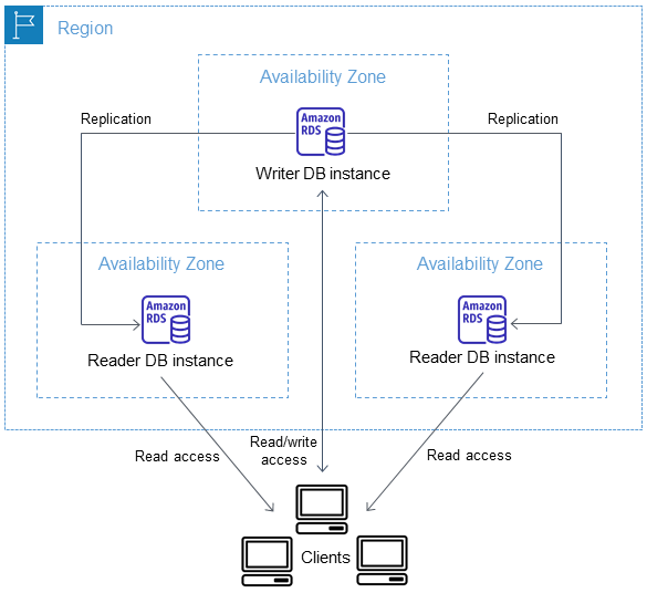
When the new Multi-AZ DB cluster deployment option is enabled, RDS configures a primary database and two read replicas in three distinct Availability Zones. It then monitors and enables failover in case of failure of the primary node.
Just like with traditional read replicas, the database engine replicates data between the primary node and the read replicas. And just like with the Multi-AZ one standby deployment option, RDS automatically detects and manages failover for high availability.
You do not have to choose between high availability or scalability; Multi-AZ DB cluster with two readable standby enables both.
What Are the Benefits?
This new deployment option offers you four benefits over traditional multi-AZ deployments: improved commit latency, faster failover, readable standby instances, and optimized replications.
First, write operations are faster when using Multi-AZ DB cluster. The new Multi-AZ DB cluster instances leverage M6gd and R6gd instance types. These instances are powered by AWS Graviton2 processors. They are equipped with fast NVMe SSD for local storage, ideal for high speed and low-latency storage. They deliver up to 40 percent better price performance and 50 percent more local storage GB per vCPU over comparable x86-based instances.
Multi-AZ DB instances use Amazon Elastic Block Store (EBS) to store the data and the transaction log. The new Multi-AZ DB cluster instances use local storage provided by the instances to store the transaction log. Local storage is optimized to deliver low-latency, high I/O operations per second (IOPS) to applications. Write operations are first written to the local storage transaction log, then flushed to permanent storage on database storage volumes.
Second, failover operations are typically faster than in the Multi-AZ DB instance scenario. The read replicas created by the new Multi-AZ DB cluster are full-fledged database instances. The system is designed to fail over as quickly as 35 seconds, plus the time to apply any pending transaction log. In case of failover, the system is fully automated to promote a new primary and reconfigure the old primary as a new reader instance.
Third, the two standby instances are hot standbys. Your applications may use the cluster reader endpoint to send their read requests (SELECT) to these standby instances. It allows your application to spread the database read load equally between the instances of the database cluster.
And finally, leveraging local storage for transaction log optimizes replication. The existing Multi-AZ DB instance replicates all changes at storage-level. The new Multi-AZ DB cluster replicates only the transaction log and uses a quorum mechanism to confirm at least one standby acknowledged the change. Database transactions are committed synchronously when one of the secondary instances confirms the transaction log is written on its local disk.
Migrating Existing Databases
For those of you having existing RDS databases and willing to take advantage of this new Multi-AZ DB cluster deployment option, you may take a snapshot of your database to create a storage-level backup of your existing database instance. Once the snapshot is ready, you can create a new database cluster, with Multi-AZ DB cluster deployment option, based on this snapshot. Your new Multi-AZ DB cluster will be a perfect copy of your existing database.
Let’s See It in Action
To get started, I point my browser to the AWS Management Console and navigate to RDS. The Multi-AZ DB cluster deployment option is available for MySQL version 8.0.28 or later and PostgreSQL version 13.4 R1 and 13.5 R1. I select either database engine, and I ensure the version matches the minimum requirements. The rest of the procedure is the same as a standard Amazon RDS database launch.
Under Deployment options, I select PostgreSQL, version 13.4 R1, and under Availability and Durability, I select Multi-AZ DB cluster.

If required, I may choose the set of Availability Zones RDS uses for the cluster. To do so, I create a DB subnet group and assign the cluster to this subnet group.
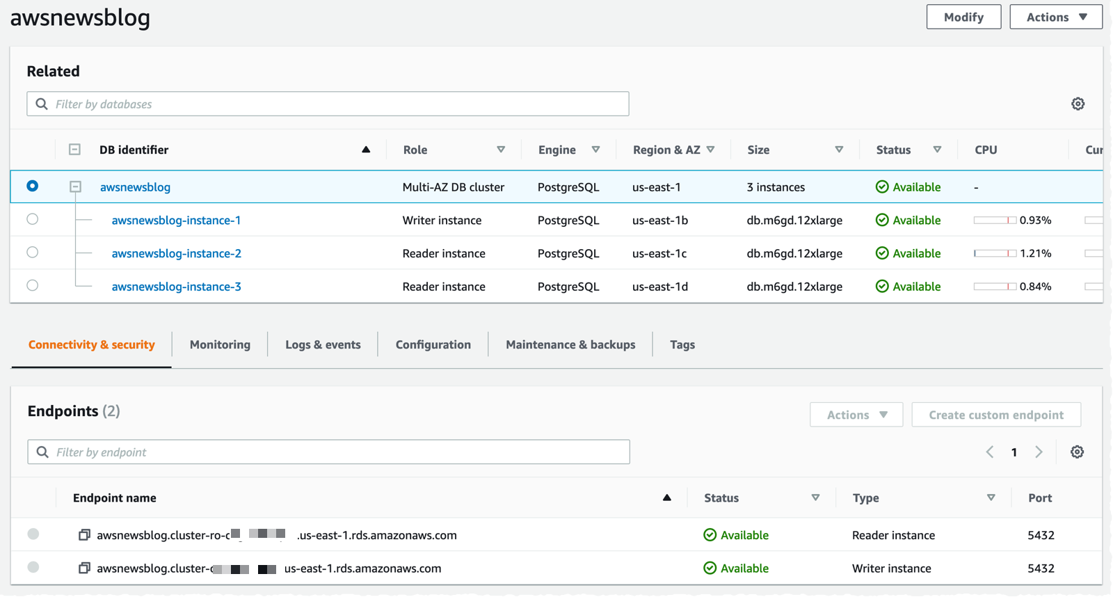
Once launched, I verify that three DB instances have been created. I also take note of the two endpoints provided by Amazon RDS: the primary endpoint and one load-balanced endpoint for the two readable standby instances.
To test the new cluster, I create an Amazon Linux 2 EC2 instance in the same VPC, within the same security group as the database, and I make sure I attach an IAM role containing the AmazonSSMManagedInstanceCore managed policy. This allows me to connect to the instance using SSM instead of SSH.
Once the instance is started, I use SSM to connect to the instance. I install PostgreSQL client tools.
sudo amazon-linux-extras enable postgresql13
sudo yum clean metadata
sudo yum install postgresql
I connect to the primary DB. I create a table and INSERT a record.
psql -h awsnewsblog.cluster-c1234567890r.us-east-1.rds.amazonaws.com -U postgres

postgres=> create table awsnewsblogdemo (id int primary key, name varchar);
CREATE TABLE

postgres=> insert into awsnewsblogdemo (id,name) values (1, 'seb');
INSERT 0 1

postgres=> exit
To verify the replication works as expected, I connect to the read-only replica. Notice the -ro- in the endpoint name. I check the table structure and enter a SELECT statement to confirm the data have been replicated.
psql -h awsnewsblog.cluster-ro-c1234567890r.us-east-1.rds.amazonaws.com -U postgres

postgres=> \dt

              List of relations
 Schema |      Name       | Type  |  Owner
--------+-----------------+-------+----------
 public | awsnewsblogdemo | table | postgres
(1 row)

postgres=> select * from awsnewsblogdemo;
 id | name
----+------
  1 | seb
(1 row)

postgres=> exit
In the scenario of a failover, the application will be disconnected from the primary database instance. In that case, it is important that your application-level code try to reestablish network connection. After a short period of time, the DNS name of the endpoint will point to the standby instance, and your application will be able to reconnect.
To learn more about Multi-AZ DB clusters, you can refer to our documentation.
Pricing and Availability
Amazon RDS Multi-AZ deployments with two readable standbys is generally available in the following Regions: US East (N. Virginia), US West (Oregon), and Europe (Ireland). We will add more regions to this list.
You can use it with MySQL version 8.0.28 or later, or PostgreSQL version 13.4 R1 or 13.5 R1.
Pricing depends on the instance type. In US regions, on-demand pricing starts at $0.522 per hour for M6gd instances and $0.722 per hour for R6gd instances. As usual, the Amazon RDS pricing page has the details for MySQL and PostgreSQL.
Post Syndicated from original https://lwn.net/Articles/886516/
Perhaps February was “compiler modernization” month. The Linux kernel
recently decided to move to the C11 standard
for its code; Python has just undergone a similar process for
determining which flavor of C to use for building its
CPython reference implementation. A calculation in the CPython interpreter
went awry when built with a pre-release version of the upcoming GCC 12; that
regression led down a path that ended up with the adoption of C11 for CPython as well.
Post Syndicated from original http://www.gatchev.info/blog/?p=2427
Професор Андрей Зубов е журналист в руския вестник „Новая газета“. Историк и религиевед, той е работил преди това като професор в МГИМО, завеждащ катедра в Руския православен университет, главен научен сътрудник в Института по изтоковедение на Руската академия на науките, доцент в Московската духовна академия… Чрез Огнян Минчев се натъкнах на великолепната му статия „Что ждет нас теперь“. И най-безсрамно я открадвам и превеждам на български тук:
—-
КАКВО НИ ОЧАКВА СЕГА
2 март 2022 г.
Откъсвайки се от всички тези ужаси, които достигат до нас от театъра на братоубийствената Руско-украинска война (именно под това име тя ще влезе в историята), и от страховете, които ежеминутно ни терзаят у дома, ми се иска да проанализирам ситуацията, така да се каже, от птичи полет.
Всяко общество прилича на пирамида по близостта си към властта и способността си да влияе на властта. В демокрациите обаче тази пирамида е полегата, с остри ъгли в основата и тъп връх, а в личностните автокрации (абсолютни монархии, тирании) е с много остър връх и ъгли при основата, твърде близки до 90 градуса. Нашето общество е характерен пример за втория тип, автократската пирамида.
„Дълбините на народа“ представляват около 80% от нея. Те са основата на пирамидата. Като правило хора, които живеят небогато или дори бедно и предпочитат телевизора пред Интернет за съставяне на картината си за света. Те или изобщо не са стъпвали зад граница, или са се задоволявали с охраняемите плажове на Турция, Египет, Тунис или Хайнан. Те са стихийни антиамериканисти, въпреки че никога не са били в Америка. Антиамериканизмът им е последствие от комплекса на завистта на фон на непросветеност. Често в главите им картината на света е омотана в теория на заговорите, псевдоистория и други странни представи. Те са пасивни и сега, макар и недоволни от живота, и са послушни на властта.
В сегашната ситуация повечето от тези хора (около 70%) поддържат войната на Путин по украинските полета и вярват в кръвожадни антируски „бандеровци“ и злобен Запад, които противостоят на Русия. Вършат го обаче без фанатизъм. Своите деца няма да искат да пратят на война и предпочитат да си спестят нейните трудности. Фанатиците сред тях са съвсем малко. Тези, които биха отишли да воюват като доброволци, ще го направят повече от нищета и отчаяние заради неуредения си живот.
Второто ниво на пирамидата са 18-19%. Това са интелигентни и културни хора, които широко използват интернет, ходят зад граница и познават добре света. Много от тях имат независими от властта източници на доходи. Други – напротив, работят в държавни корпорации или в бюрокрацията, обслужват властта, но нямат достъп до нея. Тези хора често, но не винаги живеят прилично. Могат даже да имат жилище в Латвия или България, или дори апартаментче на Лазурния. Сред тях преобладава ясното разбиране на картината на света, много имат силни нравствени принципи и ценят свободата. Други – напротив, продават таланта си на властта, и срещу мълчанието си получават нелоши заплати в университетите, бюрокроцията и близкия до властта бизнес. Немалък брой представители на тази група, потресени от последните събития, и в момента сменят лоялността си към властта с морално противопоставяне, подават си оставките от държавни служби и медии, и т.н. Но така постъпват далеч не всички лоялисти. Пример за протестното мнозинство сред тази група може да бъде актрисата Чулпан Хаматова, а на лоялното малцинство – Гергиев.
Най-сетне, върхът на пирамидата – 1-2% от населението – са бенефициентите на сегашната руска система. Това са хора изцяло предадени на властта, също образовани и разбиращи всичко. Имащи на Запад не апартаментчета, а вили, солидни влогове в западни банки (от Швейцария до ОАЕ), участващи в международния бизнес. Това са чиновници от най-висок ранг, ръководители на държавни корпорации, така наречените депутати в Думата и Съвета на Федерацията, губернатори, многозвездни генерали от армията, ФСБ и ГРУ. Те са продали свободата си на Путин и са получили в замяна богат и привилегирован живот. Те са безпрекословни изпълнители на волята му, но не по идейни, а по абсолютно користни съображения. Идеолози от сорта на Дугин или Вайно сред тях също има, но са малко. И, най-важното, идеите им са най-различни, общо е само че се опитват да ги осъществят чрез „достъп до тялото“.
Сега в тази елитна група царят ужас и фрустрация. Най-често чуваният израз в кабинетите и на Кремъл, и на Лубянка, и на Старая площадь е „той ни измами“. С Руско-украинската война Путин занули целия им сладък живот, направи недостъпни за тях парите им и вилите им в най-хубавите места по света, и на всичкото отгоре изисква от тях още повече лоялност, без да му пука, че съучастието в тази война прави много от тях поименно военни престъпници и обекти на трибунала в Хага. Такава договорка с Путин те нямат. Освен това пред тях започна да се мержелее и призракът на Големия терор, ако отхвърленият от целия свят режим продължи военната си агресия. А по-нататък ги чака и перспективата от тях да остане само ядрена пепел. Пък тая перспектива хич не е интересна за собствениците на океански яхти, колекции ролс-ройсове и ламборджинита, шедьоври на живописта и уютни вили сред тосканските лозя.
Тези хора престават да са лоялни на Путин. Защо да губят всичко накрадено, че и живота си в добавка? А без тях Путин вече е не велик тиранин, а просто стар човек, който се крие в бункер. Даже прословутият „червен бутон“, така майсторски изобразен в „Шарли Ебдо“, той вече може да натисне, ама никой няма да се задейства от това. Няколкото му фанатици не се броят. Те просто ще бъдат изолирани, заедно с направилия грешка тиранин.
Путин не може да се обърне и към по-долния етаж от пирамидата. Той или е против него, или му е лоялен по същата причина, както и „елитът“, и ще му обърне гръб заедно с елита. А към дълбините на народа съвсем не може да се обърне. Той е всичко друго, но не и народен вожд. Пък и този народ, дори да му съчувства, няма да тръгне след него. Вече е научен на пасивност и оцеляване пред телевизора, а не на народна революция.
Ако Путин беше спечелил войната в Украйна за два дни, а Западът не беше приел съкрушителни санкции, щеше да продължи да се радва на лоялността и на пълната поддръжка на народа. Даже на мистичен възторг от страна на елита, като Хитлер през 1939-41 г. Интелигенцията щеше да бъде разцепена и изолирана… Но Путин изгуби войната, не успя с блицкрига, затъна в мартенската кал на украинските черноземи. И санкциите се оказаха наистина съкрушителни, както и обеща старият президент Байдън.
И Путин остана сам. Тук не е Иран, където режимът на аятоласите се утвърди в резултат на народна религиозна революция (както и режимът на болшевиките в Русия през 1917-22 г.). Не е и Северна Корея, където в деспотизъм прерасна също народна антиколониална война. В Русия вече трийсет години царува скучна и безидейна клептократия, приела от ръцете на болшевизма смазания от него народ.
Путин занули клептократията, вече няма как да бъде неин лидер. Опозори се пред целия свят и стана за човечеството особено опасен военнопрестъпник с признаци на лудост. До няколко дни ще го отпишат. Не той, а нов лидер ще трябва да връща на върха на пирамидата „красивия живот“, да възстанови отношенията със Запада, да измоли разблокиране на банковите сметки в чуждестранните банки, да издейства отмяна на запорите върху имущества… Това ще трябва да бъде човек, неопетнен от сегашните престъпления, в идеалния случай даже осъдил ги на пълен глас, но произхождащ от техните среди. Човек, с когото те могат да се договорят.
Затова не ни грози нито нов сталинизъм, нито ирански път, нито севернокорейски. Масите в Русия са безмълвни, народна революция няма да има. Ще има, и то много-много скоро, вътрешен за върхушката преврат, подобен на смъкването на Хрушчов през 1964 г., или смъртта на император Павел на 11 септември 1801 г., или странната смърт на Сталин през март 1953 г. Но за да възстанови отношенията със Запада той ще трябва да се опира на средният, активният етаж от пирамидата, да има неговата морална поддръжка и да възстанови демокрацията и гражданските свободи. И можем да го очакваме в близките дни, най-много седмици. Оставам оптимист, господа.
Post Syndicated from Kanti Chalasani original https://aws.amazon.com/blogs/big-data/how-the-georgia-data-analytics-center-built-a-cloud-analytics-solution-from-scratch-with-the-aws-data-lab/
This is a guest post by Kanti Chalasani, Division Director at Georgia Data Analytics Center (GDAC). GDAC is housed within the Georgia Office of Planning and Budget to facilitate governed data sharing between various state agencies and departments.
The Office of Planning and Budget (OPB) established the Georgia Data Analytics Center (GDAC) with the intent to provide data accountability and transparency in Georgia. GDAC strives to support the state’s government agencies, academic institutions, researchers, and taxpayers with their data needs. Georgia’s modern data analytics center will help to securely harvest, integrate, anonymize, and aggregate data.
In this post, we share how GDAC created an analytics platform from scratch using AWS services and how GDAC collaborated with the AWS Data Lab to accelerate this project from design to build in record time. The pre-planning sessions, technical immersions, pre-build sessions, and post-build sessions helped us focus on our objectives and tangible deliverables. We built a prototype with a modern data architecture and quickly ingested additional data into the data lake and the data warehouse. The purpose-built data and analytics services allowed us to quickly ingest additional data and deliver data analytics dashboards. It was extremely rewarding to officially release the GDAC public website within only 4 months.
A combination of clear direction from OPB executive stakeholders, input from the knowledgeable and driven AWS team, and the GDAC team’s drive and commitment to learning played a huge role in this success story. GDAC’s partner agencies helped tremendously through timely data delivery, data validation, and review.
We had a two-tiered engagement with the AWS Data Lab. In the first tier, we participated in a Design Lab to discuss our near-to-long-term requirements and create a best-fit architecture. We discussed the pros and cons of various services that can help us meet those requirements. We also had meaningful engagement with AWS subject matter experts from various AWS services to dive deeper into the best practices.
The Design Lab was followed by a Build Lab, where we took a smaller cross section of the bigger architecture and implemented a prototype in 4 days. During the Build Lab, we worked in GDAC AWS accounts, using GDAC data and GDAC resources. This not only helped us build the prototype, but also helped us gain hands-on experience in building it. This experience also helped us better maintain the product after we went live. We were able to continually build on this hands-on experience and share the knowledge with other agencies in Georgia.
Our Design and Build Lab experiences are detailed below.
We wanted to stand up a platform that can meet the data and analytics needs for the Georgia Data Analytics Center (GDAC) and potentially serve as a gold standard for other government agencies in Georgia. Our objective with the AWS Data Design Lab was to come up with an architecture that meets initial data needs and provides ample scope for future expansion, as our user base and data volume increased. We wanted each component of the architecture to scale independently, with tighter controls on data access. Our objective was to enable easy exploration of data with faster response times using Tableau data analytics as well as build data capital for Georgia. This would allow us to empower our policymakers to make data-driven decisions in a timely manner and allow State agencies to share data and definitions within and across agencies through data governance. We also stressed on data security, classification, obfuscation, auditing, monitoring, logging, and compliance needs. We wanted to use purpose-built tools meant for specialized objectives.
Over the course of the 2-day Design Lab, we defined our overall architecture and picked a scaled-down version to explore. The following diagram illustrates the architecture of our prototype.
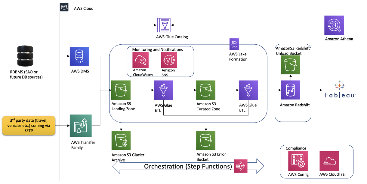
The architecture contains the following key components:
We started with planning sessions to build foundational components of our infrastructure: AWS accounts, Amazon Elastic Compute Cloud (Amazon EC2) instances, an Amazon Redshift cluster, a virtual private cloud (VPC), route tables, security groups, encryption keys, access rules, internet gateways, a bastion host, and more. Additionally, we set up AWS Identity and Access Management (IAM) roles and policies, AWS Glue connections, dev endpoints, and notebooks. Files were ingested via secure FTP, or from a database to Amazon S3 using AWS Command Line Interface (AWS CLI). We crawled Amazon S3 via AWS Glue crawlers to build Data Catalog schemas and tables for quick SQL access in Athena.
The GDAC team participated in Immersion Days for training in AWS Glue, AWS Lake Formation, and Amazon Redshift in preparation for the Build Lab.
We defined the following as the success criteria for the Build Lab:
Following a series of implementation sessions with our architect, we formed the GDAC data lake and organized downstream data pulls for the data warehouse with governed data access. Data was ingested in the raw data landing lake and then curated into a staging lake, where data was compressed and partitioned in Parquet format.
It was empowering for us to build PySpark Extract Transform Loads (ETL) AWS Glue jobs with our meticulous AWS Data Lab architect. We built reusable glue jobs for the data ingestion and curation using the code snippets provided. The days were rigorous and long, but we were thrilled to see our centralized data repository come into fruition so rapidly. Cataloging data and using Athena queries proved to be a fast and cost-effective way for data exploration and data wrangling.
The serverless orchestration with Step Functions allowed us to put AWS Glue jobs into a simple readable data workflow. We spent time designing for performance and partitioning data to minimize cost and increase efficiency.
Database access from Tableau and SQL Workbench/J were set up for my team. Our excitement only grew as we began building data analytics and dashboards using our dimensional data models.
During our post-Build Lab session, we closed several loose ends and built additional AWS Glue jobs for initial and historic loads and append vs. overwrite strategies. These strategies were picked based on the nature of the data in various tables. We returned for a second Build Lab to work on building data migration tasks from Oracle Database via VPC peering, file processing using AWS Glue DataBrew, and AWS CloudFormation for automated AWS Glue job generation. If you have a team of 4–8 builders looking for a fast and easy foundation for a complete data analytics system, I would highly recommend the AWS Data Lab.
All in all, with a very small team we were able to set up a sustainable framework on AWS infrastructure with elastic scaling to handle future capacity without compromising quality. With this framework in place, we are moving rapidly with new data feeds. This would not have been possible without the assistance of the AWS Data Lab team throughout the project lifecycle. With this quick win, we decided to move forward and build AWS Control Tower with multiple accounts in our landing zone. We brought in professionals to help set up infrastructure and data compliance guardrails and security policies. We are thrilled to continually improve our cloud infrastructure, services and data engineering processes. This strong initial foundation has paved the pathway to endless data projects in Georgia.
 Kanti Chalasani serves as the Division Director for the Georgia Data Analytics Center (GDAC) at the Office of Planning and Budget (OPB). Kanti is responsible for GDAC’s data management, analytics, security, compliance, and governance activities. She strives to work with state agencies to improve data sharing, data literacy, and data quality through this modern data engineering platform. With over 26 years of experience in IT management, hands-on data warehousing, and analytics experience, she thrives for excellence.
 Vishal Pathak is an AWS Data Lab Solutions Architect. Vishal works with customers on their use cases, architects solutions to solve their business problems, and helps them build scalable prototypes. Prior to his journey with AWS, Vishal helped customers implement BI, data warehousing, and data lake projects in the US and Australia.
Post Syndicated from Home Assistant original https://www.youtube.com/watch?v=l2ppksDTq_w
Post Syndicated from Home Assistant original https://www.youtube.com/watch?v=jIsEbQI6Ih4
Post Syndicated from Rohin Bhargava original https://aws.amazon.com/blogs/big-data/improved-performance-with-aws-graviton2-instances-on-amazon-opensearch-service/
Amazon OpenSearch Service (successor to Amazon Elasticsearch Service) is a fully managed service at AWS for OpenSearch. It’s an open-source search and analytics suite used for a broad set of use cases, like real-time application monitoring, log analytics, and website search.
While running an OpenSearch Service domain, you can choose from a variety of instances for your primary nodes and data nodes suitable for your workload: general purpose, compute optimized, memory optimized, or storage optimized. With the release of each new generation, Amazon OpenSearch Service has brought even better price performance.
Amazon OpenSearch Service now supports AWS Graviton2 instances: general purpose (M6g), compute optimized (C6g), memory optimized (R6g), and memory optimized with attached disk (R6gd). These instances offer up to a 38% improvement in indexing throughput, 50% reduction in indexing latency, and 40% improvement in query performance depending upon the instance family and size compared to the corresponding intel-based instances from the current generation (M5, C5, R5).
The AWS Graviton2 instance family includes several new performance optimizations, such as larger caches per core, higher Amazon Elastic Block Store (Amazon EBS) throughput than comparable x86 instances, fully encrypted RAM, and many others. You can benefit from these optimizations with minimal effort by provisioning or migrating your OpenSearch Service instances today.
We conducted tests using the AWS Graviton2 instances against the fifth-generation intel-based instances and measured performance improvements. Our setup included two six-node domains with three dedicated primary nodes and three data nodes and running Elasticsearch 7.10. For the intel-based setup, we used c5.xlarge for the primary nodes and r5.xlarge for the data nodes. Similarly on the AWS Graviton2-based setup, we used c6g.xlarge for the primary nodes and r6g.xlarge for the data nodes. Both domains were three Availability Zone enabled and VPC enabled, with advanced security and 512 GB of EBS volume attached to each node. Each index had six shards with a single replica.
The dataset contained 2,000 documents with a flat document structure. Each document had 20 fields: 1 date field, 16 text fields, 1 float field, and 2 long fields. Documents were generated on the fly using random samples so that the corpus was infinite.
For ingestion, we used a load generation host where each bulk request had a 4 MB payload (approximately 2,048 documents per request) and nine clients.
We used one query generation host with one client. We ran a mix of low-latency queries (approximately 10 milliseconds), medium-latency queries (100 milliseconds) , and high-latency queries (1,000 milliseconds):
We ran 60 minutes of burn-in time followed by 3 hours of 90/10 ingest to query workloads with a mix of 20% low-latency, 50% medium-latency, and 30% high-latency queries. The amount of load sent to the clusters was identical.
When ingesting documents at the same throughput, the AWS Graviton2 domain shows a much lower latency than the intel-based domain, as shown in the following graph. Even at p99 latency, the AWS Graviton2 domain is consistently lower than the p50 latency of the intel-based domains. In addition, AWS Graviton2 latencies are more consistent than intel-based instances, providing for a more predictable user experience.

When querying documents at the same throughput, the AWS Graviton2 domain outperforms the intel-based instances. The p50 latency of AWS Graviton2 is better than the p50 latency of intel-based.

Similarly, the p99 latency of AWS Graviton2 is better than that of the intel-based instances. Note in the following graph that the increase in latency over time is due to the growing corpus size.

As demonstrated in our performance analysis, the new AWS Graviton2-based instances consistently yield better performance compared to the fifth-generation intel-based instances. Try these new instances out and let us know how they perform for you!
As usual, let us know your feedback.
 Rohin Bhargava is a Sr. Product Manager with the Amazon OpenSearch Service team. His passion at AWS is to help customers find the correct mix of AWS services to achieve success for their business goals.
 Chase Engelbrecht is a Software Engineer working with the Amazon OpenSearch Service team. He is interested in performance tuning and optimization of OpenSearch running on Amazon OpenSearch Service.
Post Syndicated from Jason Pedreza original https://aws.amazon.com/blogs/big-data/etl-orchestration-using-the-amazon-redshift-data-api-and-aws-step-functions-with-aws-sdk-integration/
Extract, transform, and load (ETL) serverless orchestration architecture applications are becoming popular with many customers. These applications offers greater extensibility and simplicity, making it easier to maintain and simplify ETL pipelines. A primary benefit of this architecture is that we simplify an existing ETL pipeline with AWS Step Functions and directly call the Amazon Redshift Data API from the state machine. As a result, the complexity for the ETL pipeline is reduced.
As a data engineer or an application developer, you may want to interact with Amazon Redshift to load or query data with a simple API endpoint without having to manage persistent connections. The Amazon Redshift Data API allows you to interact with Amazon Redshift without having to configure JDBC or ODBC connections. This feature allows you to orchestrate serverless data processing workflows, design event-driven web applications, and run an ETL pipeline asynchronously to ingest and process data in Amazon Redshift, with the use of Step Functions to orchestrate the entire ETL or ELT workflow.
This post explains how to use Step Functions and the Amazon Redshift Data API to orchestrate the different steps in your ETL or ELT workflow and process data into an Amazon Redshift data warehouse.
AWS Lambda is typically used with Step Functions due to its flexible and scalable compute benefits. An ETL workflow has multiple steps, and the complexity may vary within each step. However, there is an alternative approach with AWS SDK service integrations, a feature of Step Functions. These integrations allow you to call over 200 AWS services’ API actions directly from your state machine. This approach is optimal for steps with relatively low complexity compared to using Lambda because you no longer have to maintain and test function code. Lambda functions have a maximum timeout of 15 minutes; if you need to wait for longer-running processes, Step Functions standard workflows allows a maximum runtime of 1 year.
You can replace steps that include a single process with a direct integration between Step Functions and AWS SDK service integrations without using Lambda. For example, if a step is only used to call a Lambda function that runs a SQL statement in Amazon Redshift, you may remove the Lambda function with a direct integration to the Amazon Redshift Data API’s SDK API action. You can also decouple Lambda functions with multiple actions into multiple steps. An implementation of this is available later in this post.
We created an example use case in the GitHub repo ETL Orchestration using Amazon Redshift Data API and AWS Step Functions that provides an AWS CloudFormation template for setup, SQL scripts, and a state machine definition. The state machine directly reads SQL scripts stored in your Amazon Simple Storage Service (Amazon S3) bucket, runs them in your Amazon Redshift cluster, and performs an ETL workflow. We don’t use Lambda in this use case.
In this scenario, we simplify an existing ETL pipeline that uses Lambda to call the Data API. AWS SDK service integrations with Step Functions allow you to directly call the Data API from the state machine, reducing the complexity in running the ETL pipeline.
The entire workflow performs the following steps:

The following architecture diagram highlights the end-to-end solution:
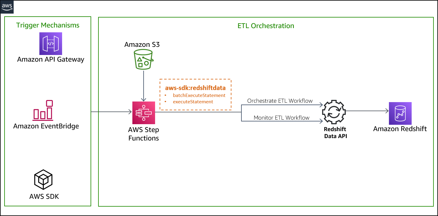
We run the state machine via the Step Functions console, but you can run this solution in several ways:
You can deploy the solution with the provided CloudFormation template, which creates the following resources:
customer_address recordsitem recordscustomercustomer_addressdate_dimitemstore_salesStateMachineExecutionRole for Step Functions to allow the following permissions:
getClusterCredentials permission avoiding password credentialsRedshiftETLStepFunction, which contains the steps used to run the ETL workflow of the sample sales data pipelineAs a prerequisite for deploying the solution, you need to set up an Amazon Redshift cluster and associate it with an IAM role. For more information, see Authorizing Amazon Redshift to access other AWS services on your behalf. If you don’t have a cluster provisioned in your AWS account, refer to Getting started with Amazon Redshift for instructions to set it up.
When the Amazon Redshift cluster is available, perform the following steps:
ETLScriptS3Path input parameter.etl-orchestration-with-stepfunctions-and-redshift-data-api.yaml).

When the stack is complete, you can view the outputs, as shown in the following screenshot:

After you deploy the CloudFormation template, navigate to the stack detail page. On the Resources tab, choose the link for RedshiftETLStepFunction to be redirected to the Step Functions console.

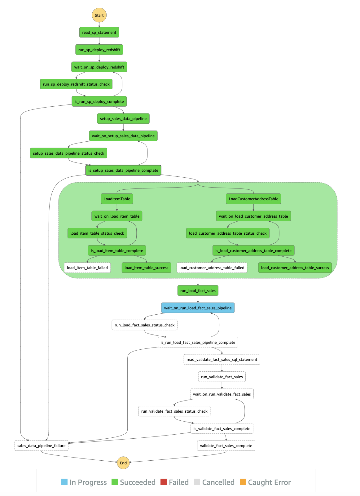
The RedshiftETLStepFunction state machine runs automatically, as outlined in the following workflow:
sp_statements.sql from Amazon S3 to get the stored procedure.batch-execute-statement API to run in the Amazon Redshift cluster.describeStatement to get the status of the API call.sales_data_pipeline_failure step and fail the ETL workflow.wait_on_sp_deploy_redshift step to wait for the SQL statements to finish.setup stored procedure that was previously created in the Amazon Redshift cluster.describeStatement to get the status of the API call.customer_address and item) and one fact table (sales).sales_data_pipeline_failure step and fail the ETL workflow.wait_on_setup_sales_data_pipeline step to wait for the SQL statements to finish.LoadItemTable and LoadCustomerAddressTable are two parallel workflows that Step Functions runs at the same time. The workflows run the stored procedures that were previously created. The stored procedure loads the data into the item and customer_address tables. All other steps in the parallel sessions follow the same concept as described previously. When both parallel workflows are complete, run_load_fact_sales runs.store_sales table that was created in the initial stored procedure.validate_sql_statement.sql) and runs the two SQL statements using the batch_execute_statement method.The implementation of the ETL workflow is idempotent. If it fails, you can retry the job without any cleanup. For example, it recreates the stg_store_sales table each time, then deletes the target table store_sales with the data for the particular refresh date each time.
The following diagram illustrates the state machine workflow:
In this example, we use the task state resource arn:aws:states:::aws-sdk:redshiftdata:[apiAction] to call the corresponding Data API action. The following table summarizes the Data API actions and their corresponding AWS SDK integration API actions.
| Amazon Redshift Data API Actions | AWS SDK Integrations API Actions |
| BatchExecuteStatement | batchExecuteStatement |
| ExecuteStatement | executeStatement |
| DescribeStatement | describeStatement |
| CancelStatement | cancelStatement |
| GetStatementResult | getStatementResult |
| DescribeTable | describeTable |
| ListDatabases | listDatabases |
| ListSchemas | listSchemas |
| ListStatements | listStatements |
| ListTables | listTables |
To use AWS SDK integrations, you specify the service name and API call, and, optionally, a service integration pattern. The AWS SDK action is always camel case, and parameter names are Pascal case. For example, you can use the Step Functions action batchExecuteStatement to run multiple SQL statements in a batch as a part of a single transaction on the Data API. The SQL statements can be SELECT, DML, DDL, COPY, and UNLOAD.
The entire ETL workflow takes approximately 1 minute to run. The following screenshot shows that the ETL workflow completed successfully.

When the entire sales data pipeline is complete, you may go through the entire execution event history, as shown in the following screenshot.

After you validate the sales data pipeline, you may opt to run the data pipeline on a daily schedule. You can accomplish this with Amazon EventBridge.
RedshiftETLStepFunction state machine daily.
RedshiftETLStepFunction state machine on a schedule, choose Schedule and define the appropriate frequency needed to run the sales data pipeline.
RedshiftETLStepFunction and choose Create.
You can confirm the schedule on the rule details page.

Clean up the resources created by the CloudFormation template to avoid unnecessary cost to your AWS account. You can delete the CloudFormation stack by selecting the stack on the AWS CloudFormation console and choosing Delete. This action deletes all the resources it provisioned. If you manually updated a template-provisioned resource, you may see some issues during cleanup; you need to clean these up independently.
The Data API and Step Functions AWS SDK integration offers a robust mechanism to build highly distributed ETL applications within minimal developer overhead. Consider the following limitations when using the Data API and Step Functions:
In this post, we demonstrated how to build an ETL orchestration using the Amazon Redshift Data API and Step Functions with AWS SDK integration.
To learn more about the Data API, see Using the Amazon Redshift Data API to interact with Amazon Redshift clusters and Using the Amazon Redshift Data API.
 Jason Pedreza is an Analytics Specialist Solutions Architect at AWS with over 13 years of data warehousing experience. Prior to AWS, he built data warehouse solutions at Amazon.com. He specializes in Amazon Redshift and helps customers build scalable analytic solutions.
 Bipin Pandey is a Data Architect at AWS. He loves to build data lake and analytics platforms for his customers. He is passionate about automating and simplifying customer problems with the use of cloud solutions.
 David Zhang is an AWS Solutions Architect who helps customers design robust, scalable, and data-driven solutions across multiple industries. With a background in software development, David is an active leader and contributor to AWS open-source initiatives. He is passionate about solving real-world business problems and continuously strives to work from the customer’s perspective. Feel free to connect with him on LinkedIn.
Post Syndicated from Nate Crampton original https://blog.rapid7.com/2022/03/02/insightappsec-github-integration-keeps-risky-code-from-reaching-production/

We’ve all been there. The software development life cycle (SDLC) is moving at a mile a minute. Developers are writing code, updating features, and all the while attempting to keep everything introduced into production as safe and secure as possible. GitHub Actions are essential to automation and allow you to build, test, and deploy your code right from GitHub, faster than ever.
But it comes with risks.
How can you be sure your running applications aren’t vulnerable to exploitation? How will we know it’s problematic before it gets into production? Can we realistically perform kick-off, test, and provide feedback to development not using automation?
A DevSecOps mindset is needed, with security baked into the SDLC — and now, GitHub Actions makes this easier than ever. This new integration — offered completely free to InsightAppSec customers — allows security and development teams to automate dynamic application security testing (DAST) as part of the CI/CD build pipeline workflow. For example, you can easily configure the integration to scan your team’s work for vulnerabilities, and if high-severity vulnerabilities are found, you can have it notify and/or block risky code before it reaches production environments.
Here’s how it works:
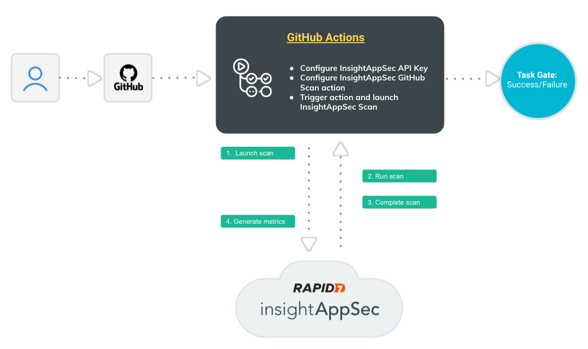
All this happens automatically, so your team isn’t spending time finding and communicating application risk — they’re focusing on building a great application security program.
That’s not where the benefits end, however.
1) It helps integrate DevOps into the Security workflow: In order to help build a Dev SecOps mindset across teams, this integration allows DevOps and Security teams to work together earlier in the lifecycle, improving cross-team outcomes and making your organization safer.
2) Automate DAST as part of your CI/CD workflow: This integration fits in seamlessly with what you’re already doing, and automatically provides the vulnerability information your teams need to stay aware of risk and keep unsafe code out of your prod environments.
3) Quick and easy setup: Simply add the IAS Scan steps to your build pipeline as defined in the insightappsec-scan-github-action repo (assuming you have valid Github and InsightAppSec licenses).
And it is all for free. We’re continuously working to make InsightAppSec the easiest and most powerful security platform for your web applications and teaming with Github will supercharge your development lifecycle in the safest way possible, automatically.
Want to learn more? Here’s what you need to know about this integration.
Additional reading:
Post Syndicated from Talks at Google original https://www.youtube.com/watch?v=rBwegbUoNpQ
Post Syndicated from Lillie Atkins original https://aws.amazon.com/blogs/big-data/announcing-the-new-amazon-quicksight-community/
On February 22, 2022, we launched our new Amazon QuickSight Community. Here you can ask and answer questions, network with and learn from other Business Intelligence (BI) users from across the globe, access learning content, and stay up to date with what’s new on Amazon QuickSight—all in one place!
In this post, we discuss some of the features of the QuickSight Community and show you how to sign up, start posting, create a profile and set up notifications.
The QuickSight Community has three main sections:


This QuickSight Community does not require any login to search or browse existing content. You only need to create an account if you want to interact with the community (such as liking posts, replying to posts, and posting your own questions).
This is a public community, so be careful not to post any confidential or private information.
To sign up, complete the following steps:


You can now contribute to the Community. Welcome!
You need to be logged in with an account to start asking questions. Before you post a question, search the recommended questions to make sure your question hasn’t already been answered.
To post a question, complete the following steps:


To view your profile and change the settings, complete the following steps:


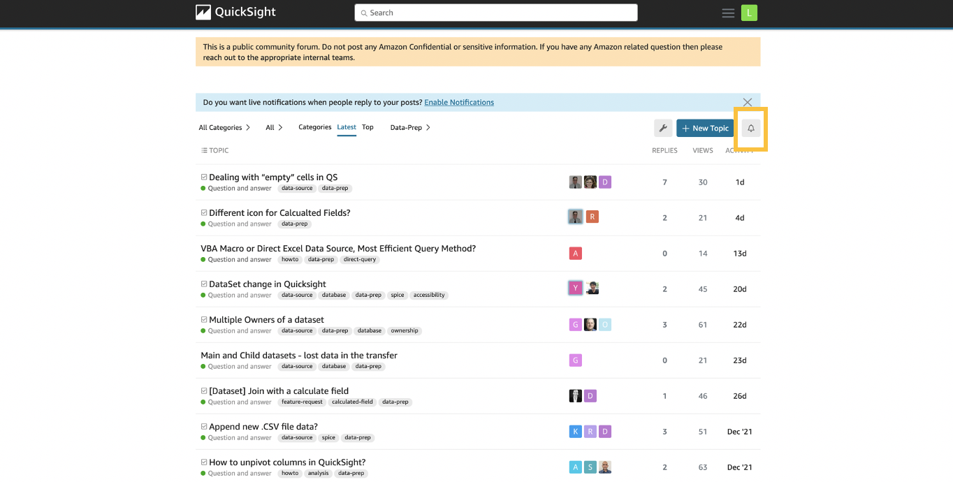
You can set up notification preferences to be alerted on a specific post, channel, or tag.
To set up notifications on a post, choose the post and then choose the notification icon to set your notification preferences.
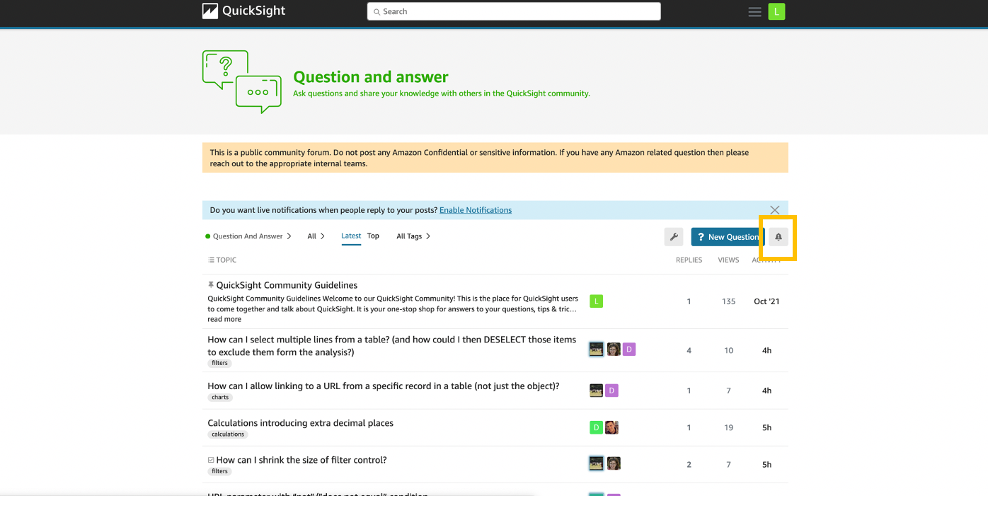
To get notified on a specific channel, go to the channel (in this case the Question and answer channel) and choose the notification bell to set your notification preferences.
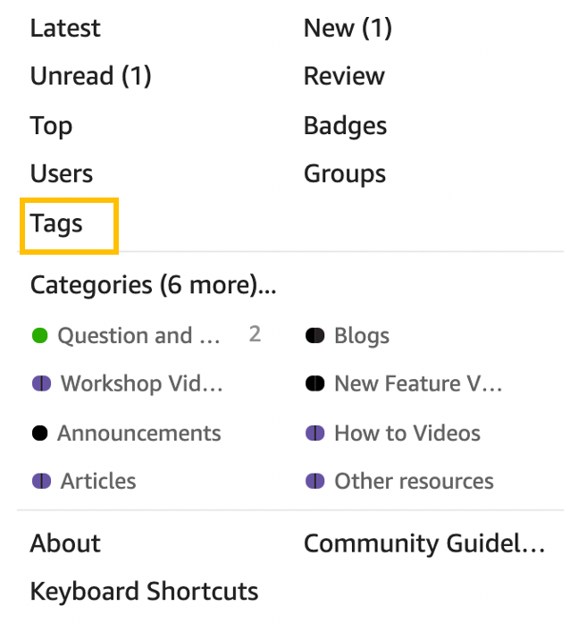
To get notified on a specific tag, complete the following steps:


In this post, we discussed the new Amazon QuickSight Community, and how you can sign up for it, create a post, edit your profile, and set up notifications. The QuickSight Community is a one-stop shop for all of your QuickSight learning needs, and a place to network with other BI users from around the globe. Start exploring today!
 Lillie Atkins is a Product Manager for Amazon QuickSight, Amazon Web Service’s cloud-native, fully managed BI service.
 Mia Heard is a Product Marketing Manager for Amazon QuickSight, AWS’ cloud-native, fully managed BI service.
Post Syndicated from BeardedTinker original https://www.youtube.com/watch?v=H7b7ohX4lgM
Post Syndicated from Sai Parthasaradhi original https://aws.amazon.com/blogs/architecture/disaster-recovery-approaches-for-db2-databases-on-aws/
As you migrate your critical enterprise workloads from an IBM Db2 on-premises database to the AWS Cloud, it’s critical to have a reliable and effective disaster recovery (DR) strategy. This helps the database applications operate with little or no disruption from unexpected events like a natural disaster.
Recovery point objective (RPO), recovery time objective (RTO), and cost, are three key metrics to consider when developing your DR strategy, (see Figure 1.) Based on these metrics, you can define your DR strategy for Db2 databases on AWS. It can be either an on-demand backup restore approach or nearly continuous replication method.

Figure 1. Disaster recovery strategies
In this post, we show an overview of active/passive cross-Region disaster recovery options for the Db2 database on Amazon Elastic Compute Cloud (Amazon EC2). This solution uses native Db2 features and AWS services such as Amazon Simple Storage Service (Amazon S3), Amazon Elastic File System (Amazon EFS), and Amazon VPC Peering connection.
In this approach, the transactional log files produced by the primary database are made available to the standby database via a log archive location. The transaction logs from the archive location can be replayed on the standby database by manually applying the Rollforward command, or by setting up user exit programs.
We can use Amazon S3 or Amazon EFS as the log archive location to share the logs with the standby database hosted in a secondary AWS Region.
Using Amazon S3:
Starting Db2 11.5.7, we can specify DB2REMOTE Amazon S3 storage for LOGARCHMETH1 and LOGARCHMETH2 database log archive method configuration parameters. This enables us to archive/retrieve transaction logs to/from Amazon S3.
In Figure 2, we enable Amazon S3 Cross-Region Replication (CRR) between the S3 buckets in the primary and the DR AWS Regions. This permits the transaction logs to be replicated into the S3 bucket in the DR Region.
We set up an AWS Lambda function to tell AWS Systems Manager (SSM) to run a command document. This document runs a bash script containing Rollforward command on the standby database instance. The Lambda function can be invoked based on the S3 bucket events in the DR Region.

Figure 2. Db2 log shipping using S3 Cross-Region Replication
This approach works as follows:
Using Amazon EFS:
In this approach, we configure the database parameter LOGARCHMETH1 with Amazon EFS as an archive location for transaction logs using the DISK option. It will push the transaction logs to a directory on Amazon EFS.
As shown in Figure 3, we configure a Replication for Amazon EFS to automatically replicate the database archive logs to the EFS in the DR Region. This can be mounted on the standby database.

Figure 3. Db2 log shipping using Amazon EFS replication
This approach replicates transaction logs to EFS. We can schedule a script for every few minutes that runs the Rollforward command to replay the logs on the standby database.
Alternatively, we can use the user exit programs provided along with the Db2 installation. This automatically applies the logs with the log archive method LOGARCHMETH1 with the parameter value set to USEREXIT.
This approach has the following advantages:
Limitations of this approach are as follows:
In this approach, we set up Db2 Highly Available and Disaster Recovery (HADR) to deploy an auxiliary Db2 standby database in a secondary or DR AWS Region.
The architecture for this approach is shown in Figure 4, and works as follows:

Figure 4. Db2 HADR with auxiliary standby database
This approach has the following advantages:
Limitations of this approach are as follows:
In this post, we discussed how to set up a disaster recovery Db2 database using database native features and AWS services. We discussed the advantages and restrictions for each. You can use this post as a reference for setting up the right disaster recovery approach for your database to minimize data loss and maintain business continuity. Let us know your comments, we always love your feedback!
For further reading:
Post Syndicated from original https://lwn.net/Articles/886560/
Security updates have been issued by Fedora (mingw-expat and seamonkey), openSUSE (mc, mysql-connector-java, nodejs12, and sphinx), Red Hat (kernel and kpatch-patch), SUSE (cyrus-sasl, kernel, nodejs12, and php74), and Ubuntu (glibc).
Post Syndicated from Rustam Lalkaka original https://blog.cloudflare.com/icloud-private-relay/

iCloud Private Relay is a new Internet privacy service from Apple that allows users with iOS 15, iPadOS 15, or macOS Monterey on their devices and an iCloud+ subscription, to connect to the Internet and browse with Safari in a more secure and private way. Cloudflare is proud to work with Apple to operate portions of Private Relay infrastructure.
In this post, we’ll explain how website operators can ensure the best possible experience for end users using iCloud Private Relay. Additional material is available from Apple, including “Set up iCloud Private Relay on all your devices”, and “Prepare Your Network or Web Server for iCloud Private Relay” which covers network operator scenarios in detail.
The design of the iCloud Private Relay system ensures that no single party handling user data has complete information on both who the user is and what they are trying to access.
To do this, Private Relay uses modern encryption and transport mechanisms to relay traffic from user devices through Apple and partner infrastructure before sending traffic to the destination website.
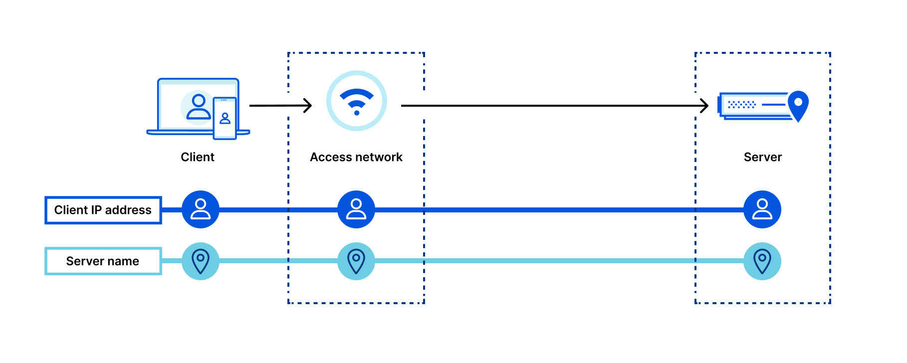
Here’s a diagram depicting what connection metadata is available to who when not using Private Relay to browse the Internet:
Let’s look at what happens when we add Private Relay to the mix:
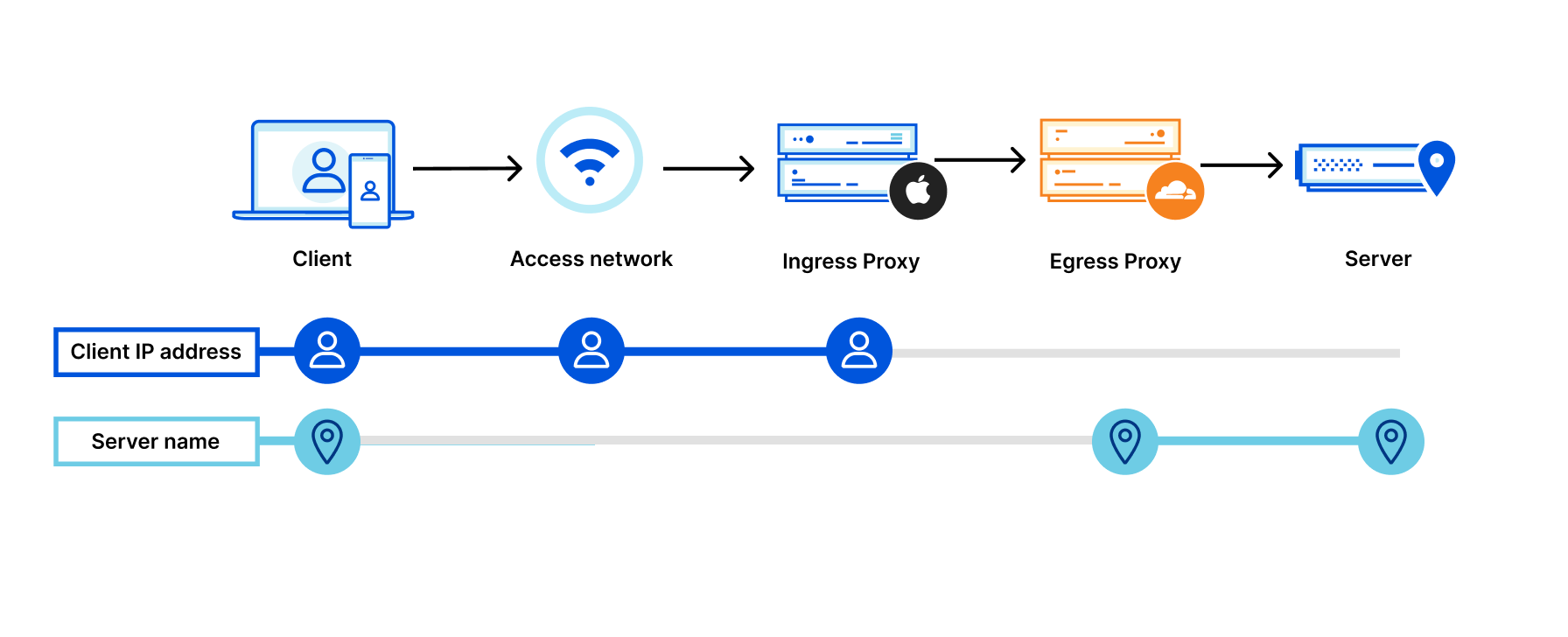
By adding two “relays” (labeled “Ingress Proxy” and “Egress Proxy” above), connection metadata is split:
The first relay hands encrypted data to a second relay (e.g. Cloudflare), but is unable to see “inside” the traffic to Cloudflare.
Splitting connections in this way prevents websites from seeing user IP addresses and minimizes how much information entities “on path” can collect on user behavior.
Much more extensive information on how Private Relay works is available from Apple, including in the whitepaper “iCloud Private Relay Overview” (pdf).
As mentioned above, Cloudflare functions as a second relay in the iCloud Private Relay system. We’re well suited to the task — Cloudflare operates one of the largest, fastest networks in the world. Our infrastructure makes sure traffic reaches every network in the world quickly and reliably, no matter where in the world a user is connecting from.
We’re also adept at building and working with modern encryption and transport protocols, including TLS 1.3 and QUIC. QUIC, and closely related MASQUE, are the technologies that enable Private Relay to efficiently move data between multiple relay hops without incurring performance penalties.
The same building blocks that power Cloudflare products were used to build support for Private Relay: our network, 1.1.1.1, Cloudflare Workers, and software like quiche, our open-source QUIC (and now MASQUE) protocol handling library, which now includes proxy support.
We’ve gone out of our way to ensure the use of iCloud Private Relay does not have any noticeable impact on your websites, APIs, and other content you serve on the web.
IP addresses are often used by website operators to “geolocate” users, with user locations being used to show content specific to certain locations (e.g. search results) or to otherwise customize user experiences. Private Relay is designed to preserve IP address to geolocation mapping accuracy, even while preventing tracking and fingerprinting.
Preserving the ability to derive rough user location ensures that users with Private Relay enabled are able to:
One of the key “acceptance tests” we think about when thinking about geolocating users is the “local pizza test”: with location services disabled, are the results returned for the search term “pizza near me” geographically relevant? Because of the geography preserving and IP address management systems we operate, they are!
At a high-level, here’s how it works:
In most parts of the world, Private Relay supports geolocation to the nearest city by default. If users prefer to be located at more coarse location granularity, the option to locate based on country and timezone is available in Private Relay settings.
If your website relies on geolocation of client IP addresses to power or modify user experiences, please ensure your geolocation database is kept up to date. Apple and Cloudflare work directly with every major IP to geolocation provider to ensure they have an accurate mapping of Private Relay egress IP addresses (which present to your server as the client IP address) to geography. These mappings may change from time to time. Using the most up-to-date version of your provider’s database will ensure the most accurate geolocation results for all users, including those using Private Relay.
In addition to making sure your geolocation databases are up-to-date, even greater location accuracy and precision can be obtained by ensuring your origin is reachable via IPv6. Private Relay egress nodes prefer IPv6 whenever AAAA DNS records are available, and use IPv6 egress IP addresses that are geolocated with greater precision than their IPv4 equivalents. This means you can geolocate users to more specific locations (without compromising user privacy) and deliver more relevant content to users as a result.
If you’re a website operator using Cloudflare to protect and accelerate your site, no action is needed from you. Our geolocation feeds used to enrich client requests with location metadata are kept up-to-date and include the information needed to geolocate users using iCloud Private Relay.
One of the more counterintuitive things about performance on the Internet is that adding intermediate network “hops” between a user and a server can often speed up overall network performance, rather than slow it down, if those intermediate hops are well-connected and tuned for speed.
The networks that power iCloud Private Relay are exceptionally well-connected to other networks around the world, and we spend considerable effort squeezing every last ounce of performance out of our systems every day. We even have automated systems, like Argo Smart Routing, that take data on how the Internet is performing and find the best paths across it to ensure consistent performance even in the face of Internet congestion and other “weather”.
Using Private Relay to reach websites instead of going directly to the origin server can result in significant, measured decreases in page load time for clients using Private Relay vs those that are not. That’s pretty neat: increased privacy does not come at the price of reduced page load and render performance when using Private Relay.
To ensure that iCloud Private Relay users have good experiences interacting with your website, you should ensure that any systems that rely on IP address as a signal or way of indexing users properly accommodate many users originating from one or a handful of addresses.
Private Relay’s concentration of users behind a given IP address is similar to commonly deployed enterprise web gateways or carrier grade network address translation (CG-NAT) systems.
As explained in Apple technical documentation, “Private Relay is designed to ensure only valid Apple devices and accounts in good standing are allowed to use the service. Websites that use IP addresses to enforce fraud prevention and anti-abuse measures can trust that connections through Private Relay have been validated at the account and device level by Apple.” Because of these advanced device and user authorization steps, you might consider allowlisting Private Relay IP addresses explicitly. Should you wish to do so, Private Relay’s egress IP addresses are available in CSV form here.
If you as a server operator are interested in managing traffic from users using systems like iCloud Private Relay or similar NAT infrastructure, consider constructing rules using user level identifiers like cookies, and other metadata present including geography.
For Cloudflare customers, our rate limiting and bot management capabilities are well suited to handle traffic from systems like Private Relay. Cloudflare automatically detects when IP addresses are likely to be used by multiple users, tuning our machine learning and other security heuristics accordingly. Additionally, our WAF includes functionality specifically designed to manage traffic originating from shared IP addresses.
As discussed above, IP addresses used by iCloud Private Relay are specific to the service. However, network and server operators (including Cloudflare customers) studying their traffic and logs may notice large amounts of user traffic arriving from Cloudflare’s network, AS13335. These traffic flows originating from AS13335 include forward proxied traffic from iCloud Private Relay, our enterprise web gateway products, and other products including WARP, our consumer VPN.
In the case of Cloudflare customers, traffic traversing our network to reach your Cloudflare proxied property is included in all usage and billing metrics as traffic from any Internet user would be.
CIOs and network administrators may have questions about how iCloud Private Relay interacts with their corporate networks, and how they might be able to use similar technologies to make their networks more secure. Apple’s document, “Prepare Your Network or Web Server for iCloud Private Relay” covers network operator scenarios in detail.
Most enterprise networks will not have to do anything to support Private Relay traffic. If the end-to-end encrypted nature of the system creates compliance challenges, local networks can block the use of Private Relay for devices connected to them.
Corporate customers of Cloudflare One services can put in place the name resolution blocks needed to disable Private Relay through their DNS filtering dashboard. Cloudflare One, Cloudflare’s corporate network security suite, includes Gateway, built on the same network and codebase that powers iCloud Private Relay.
iCloud Private Relay is an exciting step forward in preserving user privacy on the Internet, without forcing compromises in performance.
If you’re an iCloud+ subscriber you can enable Private Relay in iCloud Settings on your iPhone, iPad, or Mac on iOS15, iPadOS15, or macOS Monterey.
Post Syndicated from Pat Patterson original https://www.backblaze.com/blog/building-a-multiregion-origin-store-with-backblaze-b2-fastly-computeedge/
Backblaze B2 Cloud Storage customers have long leveraged our partner Fastly’s Deliver@Edge CDN as an essential component of a modern, scalable web architecture. Complementing Deliver@Edge, Compute@Edge is a serverless computing environment built on the same caching platform to provide a general-purpose compute layer between the cloud and end users. Today, we’re excited to celebrate Fastly’s announcement of its Compute@Edge partner ecosystem.
Serverless computing is quickly gaining popularity among developers for its simplicity, agility, and functionality. In the serverless model, cloud providers allocate resources to applications on demand, managing the compute infrastructure on behalf of their customers. The term, “serverless,” is a little misleading: The servers are actually still there, but customers don’t have to get involved in their provisioning, configuration, maintenance, or scaling.
Fastly’s Compute@Edge represents the next generation of serverless computing—purpose-built for better performance, reduced latency, and enhanced visibility and security. Using Fastly’s tools, a developer can create an edge application, test it locally, then with one command, deploy it to the Compute@Edge platform. When a request for that application reaches any of Fastly’s global network of edge servers, the application is launched and running in microseconds and can instantly scale to tens of thousands of requests per second.
It’s difficult to overstate the power and flexibility this puts in your hands as a developer—your application can be running on every edge server, with access to every attribute of its incoming requests, assembling responses in any way you choose. For an idea of the possibilities, check out the Compute@Edge demos, in particular, the implementation of the video game classic, “Doom.”
We don’t have space in a single blog post to explore an edge application of that magnitude, but read on for a simple example of how you can combine Fastly’s Compute@Edge with Backblaze B2 to improve your website’s user experience, directing requests to the optimal origin store end point based on the user’s location.
Although the CDN caches resources to improve performance, if a requested resource is not present in the edge server cache, it must be fetched from the origin store. When the edge server is close to the origin store, the increase in latency is minimal. If, on the other hand, the edge server is on a different continent from the origin store, it can take significantly longer to retrieve uncached content. In most cases, this additional delay is hardly noticeable, but for websites with many resources that are frequently updated, it can add up to a sluggish experience for users. A solution is for the origin store to maintain multiple copies of a website’s content, each at an end point in a different region. This approach can dramatically reduce the penalty for cache misses, improving the user experience.
There is a problem here, though: How do we ensure that a given CDN edge server directs requests to the “best” end point? The answer: build an application that uses the edge server’s location to select the end point. I’ll explain how I did just that, creating a Fastly Compute@Edge application to proxy requests to Backblaze B2 buckets.
The Fastly Compute@Edge developer documentation did a great job of walking me through creating a Compute@Edge application. As part of the process, I had to choose a starter kit—a simple working application targeting a specific use case. The Static Content starter kit was the ideal basis for my application—it demonstrates many useful techniques, such as generating an AWS V4 Signature and manipulating the request’s Host HTTP header to match the origin store.
The core of the application is just a few lines written in the Rust programming language:
#[fastly::main]


fn main(mut req: Request) -> Result<Response, Error> {

    // 1. Where is the application running?

    let pop = get_pop(&req);
// 2. Choose the origin based on the edge server (pop) -
// default to US if there is no match on the pop
let origin = POP_ORIGIN.get(pop.as_str()).unwrap_or(&US_ORIGIN);
// 3. Remove the query string to improve cache hit ratio
req.remove_query();
// 4. Set the `Host` header to the bucket name + host rather than
// our Compute@Edge endpoint
let host = format!("{}.{}", origin.bucket_name, origin.endpoint);
req.set_header(header::HOST, &host);
// 5. Copy the modified client request to form the backend request
let mut bereq = req.clone_without_body();
// 6. Set the AWS V4 authentication headers
set_authentication_headers(&mut bereq, &origin);
// 7. Send the request to the backend and assign its response to `beresp`
let mut beresp = bereq.send(origin.backend_name)?;
// 8. Set a response header indicating the origin that we used
beresp.set_header("X-B2-Host", &host);
// 9. Return the response to the client
return Ok(beresp);
}
In step one, the get_pop function returns the three-letter abbreviation for the edge server, or point of presence (POP). For the purposes of testing, you can specify a POP as a query parameter in your HTTP request. For example, https://three.interesting.words.edgecompute.app/image.png?pop=AMS will simulate the application running on the Amsterdam POP. Next, in step two, the application looks up the POP in a mapping of POPs to Backblaze B2 end points. There are about a hundred Fastly POPs spread around the world; I simply took the list generated by running the Fastly command-line tool with the POPs argument, and assigned POPs to Backblaze B2 end points based on their location:
I won’t step through the rest of the logic in detail here—the comments in the code sample above cover the basics; feel free to examine the code in detail on GitHub if you’d like a closer look.
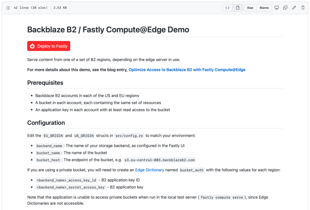
As you can see in the screenshot above, Fastly has implemented a Deploy to Fastly button. You can use this to create your own copy of the Backblaze B2 Compute@Edge demo application in just a couple of minutes. You’ll need to gather a few prerequisites before you start:
To create your second account, go to the Sign Up page, and click the Region drop-down on the right under the big, red Sign Up button:
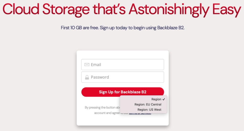
Pick the region in which you don’t already have an account, and enter an email and password. Remember, your new account comes with 10GB of storage, free of charge, so there’s no need to enter your credit card details.
Note: You’ll need to use a different email address from your existing account. If you don’t have a second email address, you can use the plus trick (officially known as sub-addressing) and reuse an existing email address. For example, if you used [email protected] for your existing B2 Cloud Storage account in the U.S. region, you can use [email protected] for your new EU account. Mail will be routed to the same inbox, and Backblaze B2 will be satisfied that it’s a different email address. This technique isn’t limited to Gmail, by the way, it works with many email providers.
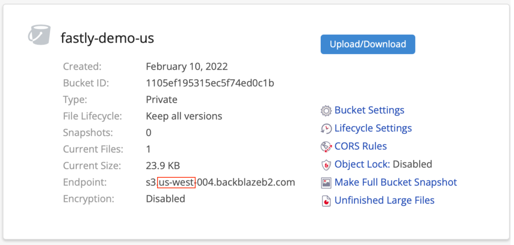
src/config.rs and hit the pencil icon near the top right to edit the file. Change the origin configuration in lines 18-31 to match your buckets and their end points. Alternatively, you can, of course, clone the repository to your local machine, edit it there, and push the changes back to GitHub.Once you have your accounts and buckets created, it takes just a few minutes to deploy the application. Watch me walk through the process:
My simple demo application only scratches the surfaces of Compute@Edge. How could you combine Fastly’s edge computing platform with Backblaze B2 to create a new capability for your website? Check out Fastly’s collection of over 100 Compute@Edge code samples for inspiration. If you come up with something neat and share it on GitHub, let me know in the comments and I’ll round up a bundle of Backblaze-branded goodies, just for you!
The post Building a Multiregion Origin Store With Backblaze B2 + Fastly Compute@Edge appeared first on Backblaze Blog | Cloud Storage & Cloud Backup.
Post Syndicated from The History Guy: History Deserves to Be Remembered original https://www.youtube.com/watch?v=sv7bhfVRzLY