Fedora 35 released

Post Syndicated from original https://lwn.net/Articles/874767/rss

The Fedora 35
release
has been announced.

No matter what variant of Fedora you use, you’re getting the latest
the open source world has to offer. Following our “First”
foundation, we’ve updated key programming language and system
library packages, including Python 3.10, Perl 5.34, and PHP
8.0. Fedora Linux 35 also includes the 1.0 release of firewalld,
the modern firewall service.

Choosing between storage mechanisms for ML inferencing with AWS Lambda

Post Syndicated from James Beswick original https://aws.amazon.com/blogs/compute/choosing-between-storage-mechanisms-for-ml-inferencing-with-aws-lambda/

This post is written by Veda Raman, SA Serverless, Casey Gerena, Sr Lab Engineer, Dan Fox, Principal Serverless SA.

For real-time machine learning inferencing, customers often have several machine learning models trained for specific use-cases. For each inference request, the model must be chosen dynamically based on the input parameters.

This blog post walks through the architecture of hosting multiple machine learning models using AWS Lambda as the compute platform. There is a CDK application that allows you to try these different architectures in your own account. Finally, it then discusses the different storage options for hosting the models and the benefits of each.

Overview

The serverless architecture for inferencing uses AWS Lambda and API Gateway. The machine learning models are stored either in Amazon S3 or Amazon EFS. Alternatively, they are part of the Lambda function deployed as a container image and stored in Amazon ECR.

All three approaches package and deploy the machine learning inference code as Lambda function along with the dependencies as a container image. More information on how to deploy Lambda functions as container images can be found here.

Solution architecture

  1. A user sends a request to Amazon API Gateway requesting a machine learning inference.
  2. API Gateway receives the request and triggers Lambda function with the necessary data.
  3. Lambda loads the container image from Amazon ECR. This container image contains the inference code and business logic to run the machine learning model. However, it does not store the machine learning model (unless using the container hosted option, see step 6).
  4. Model storage option: For S3, when the Lambda function is triggered, it downloads the model files from S3 dynamically and performs the inference.
  5. Model storage option: For EFS, when the Lambda function is triggered, it accesses the models via the local mount path set in the Lambda file system configuration and performs the inference.
  6. Model storage option: If using the container hosted option, you must package the model in Amazon ECR with the application code defined for the Lambda function in step 3. The model runs in the same container as the application code. In this case, choosing the model happens at build-time as opposed to runtime.
  7. Lambda returns the inference prediction to API Gateway and then to the user.

The storage option you choose, either Amazon S3, Amazon EFS, or Amazon ECR via Lambda OCI deployment, to host the models influences the inference latency, cost of the infrastructure and DevOps deployment strategies.

Comparing single and multi-model inference architectures

There are two types of ML inferencing architectures, single model and multi-model. In single model architecture, you have a single ML inference model that performs the inference for all incoming requests. The model is stored either in S3, ECR (via OCI deployment with Lambda), or EFS and is then used by a compute service such as Lambda.

The key characteristic of a single model is that each has its own compute. This means that for every Lambda function there is a single model associated with it. It is a one-to-one relationship.

Multi-model inferencing architecture is where there are multiple models to be deployed and the model to perform the inference should be selected dynamically based on the type of request. So you may have four different models for a single application and you want a Lambda function to choose the appropriate model at invocation time. It is a many-to-one relationship.

Regardless of whether you use single or multi-model, the models must be stored in S3, EFS, or ECR via Lambda OCI deployments.

Should I load a model outside the Lambda handler or inside?

It is a general best practice in Lambda to load models and anything else that may take a longer time to process outside of the Lambda handler. For example, loading a third-party package dependency. This is due to cold start invocation times – for more information on performance, read this blog.

However, if you are running a multi-model inference, you may want to load inside the handler so you can load a model dynamically. This means you could potentially store 100 models in EFS and determine which model to load at the time of invocation of the Lambda function.

In these instances, it makes sense to load the model in the Lambda handler. This can increase the processing time of your function, since you are loading the model at the time of request.

Deploying the solution

The example application is open-sourced. It performs NLP question/answer inferencing using the HuggingFace BERT model using the PyTorch framework (expanding upon previous work found here). The inference code and the PyTorch framework are packaged as a container image and then uploaded to ECR and the Lambda service.

The solution has three stacks to deploy:

  • MlEfsStack – Stores the inference models inside of EFS and loads two models inside the Lambda handler, the model is chosen at invocation time.
  • MlS3Stack – Stores the inference model inside of S3 and loads a single model outside of the Lambda handler.
  • MlOciStack – Stores the inference models inside of the OCI container loads two models outside of the Lambda handler, the model is chosen at invocation time.

To deploy the solution, follow along the README file on GitHub.

Testing the solution

To test the solution, you can either send an inference request through API Gateway or invoke the Lambda function through the CLI. To send a request to the API, run the following command in a terminal (be sure to replace with your API endpoint and Region):

curl --location --request POST 'https://asdf.execute-api.us-east-1.amazonaws.com/develop/' --header 'Content-Type: application/json' --data-raw '{"model_type": "nlp1","question": "When was the car invented?","context": "Cars came into global use during the 20th century, and developed economies depend on them. The year 1886 is regarded as the birth year of the modern car when German inventor Karl Benz patented his Benz Patent-Motorwagen. Cars became widely available in the early 20th century. One of the first cars accessible to the masses was the 1908 Model T, an American car manufactured by the Ford Motor Company. Cars were rapidly adopted in the US, where they replaced animal-drawn carriages and carts, but took much longer to be accepted in Western Europe and other parts of the world."}'

General recommendations for model storage

For single model architectures, you should always load the ML model outside of the Lambda handler for increased performance on subsequent invocations after the initial cold start, this is true regardless of the model storage architecture that is chosen.

For multi-model architectures, if possible, load your model outside of the Lambda handler; however, if you have too many models to load in advance then load them inside of the Lambda handler. This means that a model will be loaded at every invocation of Lambda, increasing the duration of the Lambda function.

Recommendations for model hosting on S3

S3 is a good option if you need a simpler, low-cost storage option to store models. S3 is recommended when you cannot predict your application traffic volume for inference.

Additionally, if you must retrain the model, you can upload the retrained model to the S3 bucket without redeploying the Lambda function.

Recommendations for model hosting on EFS

EFS is a good option if you have a latency-sensitive workload for inference or you are already using EFS in your environment for other machine learning related activities (for example, training or data preparation).

With EFS, you must VPC-enable the Lambda function to mount the EFS filesystem, which requires an additional configuration.

For EFS, it’s recommended that you perform throughput testing with both EFS burst mode and provisioned throughput modes. Depending on inference request traffic volume, if the burst mode is not able to provide the desired performance, you must provision throughput for EFS. See the EFS burst throughput documentation for more information.

Recommendations for container hosted models

This is the simplest approach since all the models are available in the container image uploaded to Lambda. This also has the lowest latency since you are not downloading models from external storage.

However, it requires that all the models are packaged into the container image. If you have too many models that cannot fit into the 10 GB of storage space in the container image, then this is not a viable option.

One drawback of this approach is that anytime a model changes, you must re-package the models with the inference Lambda function code.

This approach is recommended if your models can fit in the 10 GB limit for container images and you are not re-training models frequently.

Cleaning up

To clean up resources created by the CDK templates, run “cdk destroy <StackName>”

Conclusion

Using a serverless architecture for real-time inference can scale your application for any volume of traffic while removing the operational burden of managing your own infrastructure.

In this post, we looked at the serverless architecture that can be used to perform real-time machine learning inference. We then discussed single and multi-model architectures and how to load the models in the Lambda function. We then looked at the different storage mechanisms available to host the machine learning models. We compared S3, EFS, and container hosting for storing models and provided our recommendations of when to use each.

For more learning resources on serverless, visit Serverless Land.

A Matter of Perspective: Agent-Based and Agentless Approaches to Cloud Security, Part 2

Post Syndicated from Amit Bawer original https://blog.rapid7.com/2021/11/02/a-matter-of-perspective-agent-based-and-agentless-approaches-to-cloud-security-part-2-2/

A Matter of Perspective: Agent-Based and Agentless Approaches to Cloud Security, Part 2

In our previous blog on this topic, we discussed some of the considerations when choosing between agent-based and agentless cloud security approaches. The following table provides a summary of these considerations.

Aspect Agent-based Agentless
Deployment – Deployed on every asset independently

– Can add potential friction; may require some special access permissions per asset

– Deployment has to scale up with additional assets

– Can be resource-intensive for the monitored asset

– Deployed externally to assets being monitored, usually at the cluster level

– Relies on the provider’s inherent access role schemes and APIs

– Processing and data collection are independent of assets

– Can be resource-consuming at the provider’s billing level

Monitoring – Tailored for asset specifications (must be aware of and compatible with OS, kernel, and architecture of the layer in which it operates)

– Can be used over a variety of different cloud providers

– Has access to unexposed asset information, but requires elevated permissions, which may turn into a security consideration of its own

– Has a specific view per monitored asset; higher-level correlation has to be done externally

– Missing or malfunctioning deployment may result in blind spots

– May require different inspection methods for different types of assets

– Agnostic to asset specifications

– Relies on cloud provider’s API and its data collection facilities

– No access to unexposed provider information

– Has a cluster-level view of asset activities, usually from a single collection point; easy to make correlations between different cluster asset activities

– Malfunctioning deployment may result in cluster-level blindness

– Unified access to all asset information via a common API and data collection facility

Enforcement – Needs an in-band access to medium for taking an action

– May interfere with uncorrelated provider operations

– Integrates to and correlates with provider’s automations and enforcement tools

– Cannot go beyond provider’s limitations

Hybrid approach

Neither the agent-based nor agentless approach is strictly considered better than the other. In some cases, it could be beneficial to join forces and have both flavors of security scooped into the same cone, so each can cover for the shortcomings of its counterpart. For example, agentless solutions are usually shortsighted when it comes to a workload’s confined information, such as the activity of processes executed within the workload space. Therefore, you might choose to augment your agentless solution with an agent-based deployment for this purpose.

As a counter-example, agent-based solutions could be disruptive or resource-consuming for network monitoring tasks. You could instead carry out these tasks over the already existing provider facilities by adding an agentless solution, which could then catch all cluster network activity information within a single collection point.

So, what’s the right answer?

In this post, we have covered some of the key aspects that differentiate agentless and agent-based approaches to cloud security. We can conclude that neither is necessarily preferable over the other, but each can cover the shortcomings of its counterpart, depending on your organization’s needs. Agent-based solutions can potentially provide a more in-depth perspective of a protected asset’s internal activities. Provider-integrated agentless solutions are usually agnostic to the containerized internal activities, but they can excel at a broader scale when making correlations between different sources of information, while still minimizing the friction per asset.

Essentially, there’s no right or wrong answer for cloud security. To keep your assets secure, just pick the approach — or mix of approaches — that makes sense for you and your organization.

NEVER MISS A BLOG

Get the latest stories, expertise, and news about security today.

Field Notes: Extending the Baseline in AWS Control Tower to Accelerate the Transition from AWS Landing Zone

Post Syndicated from MinWoo Lee original https://aws.amazon.com/blogs/architecture/field-notes-extending-the-baseline-in-aws-control-tower-to-accelerate-the-transition-from-aws-landing-zone/

Customers who adopt and operate the AWS Landing Zone solution as a scalable multi-account environment are starting to migrate to the AWS Control Tower service. They are doing so to enjoy the added benefits of managed services such as stability, feature enhancement, and operational efficiency. Customers who fully use the baseline for governance control provided by AWS Landing Zone for their member accounts may want to apply the baseline of the same feature without omission even when transitioning to AWS Control Tower. To baseline an account is to set up common blueprints and guardrails required for an organization to enable governance at the start of the account.

As shown in Table 1, AWS Control Tower provides most of the features that are mapped with the baseline of the AWS Landing Zone solution through the baseline stacks, guardrails, and account factory, but some features are unique to AWS Landing Zone.

Table 1. AWS Landing Zone and
AWS Control Tower Baseline mapping
AWS Landing Zone baseline stack AWS Control Tower baseline stack
AWS-Landing-Zone-Baseline-EnableCloudTrail AWSControlTowerBP-BASELINE-CLOUDTRAIL
AWS-Landing-Zone-Baseline-SecurityRoles AWSControlTowerBP-BASELINE-ROLES
AWS-Landing-Zone-Baseline-EnableConfig AWSControlTowerBP-BASELINE-CLOUDWATCH
AWSControlTowerBP-BASELINE-CONFIG
AWSControlTowerBP-BASELINE-SERVICE-ROLES
AWS-Landing-Zone-Baseline-ConfigRole AWSControlTowerBP-BASELINE-SERVICE-ROLES
AWS-Landing-Zone-Baseline-EnableConfigRule Guardrails – Enable guardrail on OU
(AWSControlTowerGuardrailAWS-GR-xxxxx)
AWS-Landing-Zone-Baseline-EnableConfigRulesGlobal Guardrails – Enable guardrail on OU
(AWSControlTowerGuardrailAWS-GR-xxxxx)
AWS-Landing-Zone-Baseline-PrimaryVPC Account Factory – Network Configuration
AWS-Landing-Zone-Baseline-IamPasswordPolicy –
AWS-Landing-Zone-Baseline-EnableNotifications –

The baselines uniquely provided by AWS Landing Zone are as follows:

  • AWS-Landing-Zone-Baseline-IamPasswordPolicy
    • AWS Lambda to configure AWS Identity and Access Management (IAM) custom password policy (such as minimum password length, password expires period, password complexity, and password history in member accounts).
  • AWS-Landing-Zone-Baseline-EnableNotifications
    • Amazon CloudWatch alarms deliver CloudTrail application programming interface (API) activity such as Security Group changes, Network ACL changes, and Amazon Elastic Compute Cloud (Amazon EC2) instance type changes to the security administrator.

AWS provides the AWS Control Tower lifecycle events and Customizations for AWS Control Tower as a way to add features that are not included by default in AWS Control Tower. Customizations for AWS Control Tower is an AWS solution that allows you to easily add customizations using AWS CloudFormation templates and service control polices.

This blog post explains how to modify and deploy the code to apply AWS Landing Zone specific baselines such as IamPasswordPolicy and EnableNotifications into AWS Control Tower using Customizations for the AWS Control Tower.

Overview of solution

Adhering to the package folder structure of Customizations for AWS Control Tower, modify the AWS Landing Zone IamPasswordPolicy, EnableNotifications template, parameter file, and manifest file to match the AWS Control Tower deployment environment.

When the modified package is uploaded to the source repository, contents of the package are validated and built by launching AWS CodePipeline. The AWS Landing Zone specific baseline is deployed in member accounts through AWS CloudFormation StackSets in the AWS Control Tower management account.

When a new or existing account is enrolled in AWS Control Tower, the same AWS Landing Zone specific baseline is automatically applied to that account by the lifecycle event (CreateManagedAccount status is SUCCEEDED).

Figure 1 shows how the default baseline of AWS Control Tower and the specific baseline of AWS Landing Zone are applied to member accounts.

Figure 1. Default and custom baseline deployment in AWS Control Tower

Figure 1. Default and custom baseline deployment in AWS Control Tower

Walkthrough

This solution follows these steps:

  1. Download and extract the latest version of the AWS Landing Zone Configuration source package. The package contains several functional components including baseline of IamPasswordPolicy, EnableNotifications for applying to accounts in AWS Landing Zone environment. If you are transitioning from AWS Landing Zone to AWS Control Tower, you may use the AWS Landing Zone configuration source package that exists in your management account.
  2. Download and extract the configuration source package of your Customizations for AWS Control Tower.
  3. Create templates and parameters folder structure for customizing configuration package source of Customizations for AWS Control Tower.
  4.  Copy the template and parameter files of the IamPasswordPolicy baseline from the AWS Landing Zone configuration source to the Customizations for AWS Control Tower configuration source.
    1. Open the parameter file (JSON), and modify the parameter value to match your organization’s password policy.
  1. Copy the template and parameter files of the EnableNotifications baseline from the AWS Landing Zone configuration source to the Customizations for AWS Control Tower configuration source.
    1. Open the parameter file (JSON), and change the LogGroupName parameter value to the CloudWatch log group name of your AWS Control Tower environment. Select whether or not to use each alarm in the parameter value.
    2. Open the template file (YAML), and modify the AlarmActions properties of all CloudWatch alarms to refer to the security topic of the Amazon Simple Notification Service (Amazon SNS) that exists in your AWS Control Tower environment.
  1. Open the manifest (YAML) file in the configuration source of Customizations for AWS Control Tower, and update with the modified IamPasswordPolicy and EnableNotifications parameter, template file path, and organizational unit to be applied.
    1. If you have customizations which have already been deployed and operated through Customizations for AWS Control Tower, do not remove existing contents, and consecutively add customized resource in resources section.
  1. Compress the completed source package, and upload it to the source repository of Customizations for AWS Control Tower.
  2. Check the results for applying this solution in AWS Control Tower.
    1. In the management account, wait for all AWS CodePipeline steps in Customizations for AWS Control Tower to be completed.
    2. In the management account, check that the CloudFormation IamPasswordPolicy and EnableNotifications StackSet is deployed.
    3. In a member account, check that the custom password policy is configured in Account Settings of IAM.
    4. In a member account, check that alarms are created in All Alarms of CloudWatch.

Prerequisites

For this walkthrough, you should have the following prerequisites:

  • AWS Control Tower deployment.
  • An AWS Control Tower member account.
  • Customizations for AWS Control Tower solution deployment.
  • IAM user and roles, and permission to allow use of ‘CustomControlTowerKMSKey’ in AWS Key Management Service Key Policy to access Amazon Simple Storage Service (Amazon S3) as the configuration source.
    • This is not required in case of using CodeCommit as source repository, but it assumes that Amazon S3 is used for this solution.
  • If the IamPasswordPolicy and EnableNotifications baseline for the AWS Landing Zone service has been deployed in the AWS Control Tower environment, it is necessary to delete stack instances and StackSet associated with the following CloudFormation StackSets:
    • AWS-Landing-Zone-Baseline-IamPasswordPolicy
    • AWS-Landing-Zone-Baseline-EnableNotifications
  • An IAM or AWS Single Sign-On (AWS SSO) account with the following settings:
    • Permission with AdministratorAccess
    • Access type with Programmatic access and AWS Management Console access
  • AWS Command Line Interface (AWS CLI) and Linux Zip package installation in work environment.
  • An IAM or AWS SSO user for member account (optional).

Prepare the work environment

Download the AWS Landing Zone configuration package and Customizations for AWS Control Tower configuration package, and create a folder structure.

  1. Open your terminal AWS Command Line Interface (AWS CLI).

Note: Confirm that AWS Config and credentials for the AWS Command Line Interface (AWS CLI) are properly set as access method (IAM or AWS SSO user) you are using in management account.

  1. Change to home directory and download the aws-landing-zone-configuration.zip file.
cd ~
wget https://s3.amazonaws.com/solutions-reference/aws-landing-zone/latest/aws-landing-zone-configuration.zip
  1.  Extract AWS Landing Zone configuration file to new directory (Named alz).
unzip aws-landing-zone-configuration.zip -d ~/alz
  1. Download _custom-control-tower-configuration.zip file in Customizations for AWS Control Tower configuration’s S3 bucket. Use your AWS Account Id and home Region in S3 bucket name.

Note: If you have already used the Customizations for AWS Control Tower configuration package, or have the Auto Build parameter set to true, use custom-control-tower-configuration.zip instead of _custom-control-tower-configuration.zip.

aws s3 cp s3://custom-control-tower-configuration-<AWS Account Id >-<AWS Region>/_custom-control-tower-configuration.zip ~/

Figure 2. Downloading source package of Customizations for AWS Control Tower

  1. Extract Customizations for AWS Control Tower configuration file to new directory (Named cfct).
unzip _custom-control-tower-configuration.zip -d ~/cfct
  1. Create templates and parameters directory under Customizations for AWS Control Tower configuration directory.
cd ~/cfct
mkdir templates parameters

Now you will see directories and files under Customizations for AWS Control Tower configuration directory.

Note: example-configuration is just an example, and will not be used in this blog post.

 Figure 3. Directory structure of Customizations for AWS Control Tower

Figure 3. Directory structure of Customizations for AWS Control Tower

Customize to include AWS Landing Zone specific baseline

Start customization work by integrating the AWS Landing Zone IamPasswordPolicy and EnableNotifications baseline related files into the structure of Customizations for AWS Control Tower configuration package.

  1. Copy the IamPasswordPolicy baseline template and parameter file into the Customizations for AWS Control Tower configuration directory.
cp ~/alz/templates/aws_baseline/aws-landing-zone-iam-password-policy.template ~/cfct/templates/
cp ~/alz/parameters/aws_baseline/aws-landing-zone-iam-password-policy.json ~/cfct/parameters/
  1. Open the copied aws-landing-zone-iam-password-policy.json, then adjust it to be compliant with your optional password policy requirement.
  2. Copy the EnableNotifications baseline template and parameter file into the Customizations for AWS Control Tower configuration directory.
cp ~/alz/templates/aws_baseline/aws-landing-zone-notifications.template ~/cfct/templates/
cp ~/alz/parameters/aws_baseline/aws-landing-zone-notifications.json ~/cfct/parameters/
  1. Open the copied aws-landing-zone-notifications.template.

Remove the following four lines from the SNSNotificationTopic parameter:

SNSNotificationTopic:
    Type: AWS::SSM::Parameter::Value<String>
    Default: /org/member/local_sns_arn
    Description: "Local Admin SNS Topic for Landing Zone"

Modify AlarmActions under Properties for each of 11 CloudWatch alarms as follows:

AlarmActions:
      - !Sub 'arn:aws:sns:${AWS::Region}:${AWS::AccountId}:aws-controltower-SecurityNotifications'
  1. Open aws-landing-zone-notifications.json.

Remove the following five lines from the SNSNotificationTopic parameter key, and parameter value at the bottom of file. Make sure to remove the including comma preceding the JSON syntax.

  ,
  {
    "ParameterKey": "SNSNotificationTopic",
    "ParameterValue": "/org/member/local_sns_arn"
  }

     Modify the parameter value of LogGroupName parameter key as follows:

{
"ParameterKey": "LogGroupName",
"ParameterValue": "aws-controltower/CloudTrailLogs"
},

6. Open the manifest.yaml under root of the Customizations for AWS Control Tower configuration directory, then modify it to include IamPasswordPolicy and EnableNotifications baseline. If there are customizations that  have been previously used in the manifest file of Customizations for AWS Control Tower, add them at the end.

7. Properly adjust region, resource_file, parameter_file, and organizational_units for your AWS Control Tower environment.

Note: Choose the proper organizational units because Customizations for AWS Control Tower will try to deploy customization resources to all AWS accounts within operational units defined in organizational_units property. If you want to select specific accounts, consider using accounts property instead of organizational_units property.

Review the following sample manifest file:

---
#Default region for deploying Custom Control Tower: Code Pipeline, Step functions, Lambda, SSM parameters, and StackSets
region: ap-northeast-2
version: 2021-03-15

# Control Tower Custom Resources (Service Control Policies or CloudFormation)
resources:
  - name: IamPasswordPolicy
    resource_file: templates/aws-landing-zone-iam-password-policy.template
    parameter_file: parameters/aws-landing-zone-iam-password-policy.json
    deploy_method: stack_set
    deployment_targets:
      organizational_units:
        - Security
        - Infrastructure
        - app-services
        - app-reports

  - name: EnableNotifications
    resource_file: templates/aws-landing-zone-notifications.template
    parameter_file: parameters/aws-landing-zone-notifications.json
    deploy_method: stack_set
    deployment_targets:
      organizational_units:
        - Security
        - Infrastructure
        - app-services
        - app-reports
  1. Compress all files within the root of the Customizations for AWS Control Tower configuration directory into the custom-control-tower-configuration.zip file.
cd ~/cfct/
zip -r custom-control-tower-configuration.zip ./
  1. Upload the custom-control-tower-configuration.zip file into the Customizations for AWS Control Tower configuration S3 bucket. Use your AWS Account Id and Home Region in the S3 bucket name.
aws s3 cp ~/cfct/custom-control-tower-configuration.zip s3://custom-control-tower-configuration-<AWS Account Id>-<AWS Region>/

Figure 4. Uploading source package of Customizations for AWS Control Tower

Verify solution

Now, you can verify the results for applying this solution.

  1. Log in to your AWS Control Tower management account.
  2.  Navigate to AWS CodePipeline service, then select Custom-Control-Tower-CodePipeline.
  3. Wait for all pipeline stages to complete.
  4. Go to AWS CloudFormation, then choose StackSets.
  5.  Search with the keyword custom. This will result in two custom StackSets.

Figure 5. Custom StackSet of Customizations for AWS Control Tower

  1. Log in to your AWS Control Tower member account.

Note: You need an IAM or AWS SSO user, or simply switch the role to AWSControlTowerExecution in the member account.

  1. Go to IAM, then choose Account settings. You will see a configured custom password policy.
Figure 6. IAM custom password policy of member account

Figure 6. IAM custom password policy of member account

  1. Go to Amazon CloudWatch, then choose All alarms. You will see 11 configured alarms.

Figure 7. Amazon CloudWatch alarms of member account

Cleaning up

Resources deployed to member accounts by this solution can be removed through the CloudFormation Stack function in the management account.

Run Delete stack from StackSet, followed by Delete StackSet, for the following two StackSets.

  • CustomControlTower-IamPasswordPolicy
  • CustomControlTower-EnableNotifications

Conclusion

In this blog post, you learned how to extend the baseline in AWS Control Tower to include the baseline specific to AWS Landing Zone. The principal idea is to use Customizations for AWS Control Tower, and additionally add guardrails, such as AWS Config rule and service control policy, which are not included by default in AWS Control Tower. This helps the transition of AWS Landing Zone to the AWS Control Tower, and enhances the governance control capability of the enterprise.

Related reading: Seamless Transition from an AWS Landing Zone to AWS Control Tower

Field Notes provides hands-on technical guidance from AWS Solutions Architects, consultants, and technical account managers, based on their experiences in the field solving real-world business problems for customers.

How we build software at Cloudflare

Post Syndicated from Nick Wood original https://blog.cloudflare.com/building-software-at-cloudflare/

How we build software at Cloudflare

How we build software at Cloudflare

Cloudflare provides a broad range of products — ranging from security, to performance and serverless compute — which are used by millions of Internet properties worldwide. Often, these products are built by multiple teams in close collaboration and delivering them can be a complex task. So ever wondered how we do so consistently and safely at scale?

Software delivery consists of all the activities to get working software into the hands of customers. It’s usual to talk about software delivery with reference to a model, or framework. These provide the scaffolding for most modern software delivery models, although in order to minimise operational friction it’s usual for a company to tailor their approach to suit their business context and culture.

For example, a company that designs the autopilot systems for passenger aircraft will require very strict tolerances, as a failure could cost hundreds of lives. They would want a different process to a cutting edge tech startup, who may value time to market over system uptime or stability.

Before outlining the approach we use at Cloudflare it’s worth quickly running through a couple of commonly used delivery models.

The Waterfall Approach

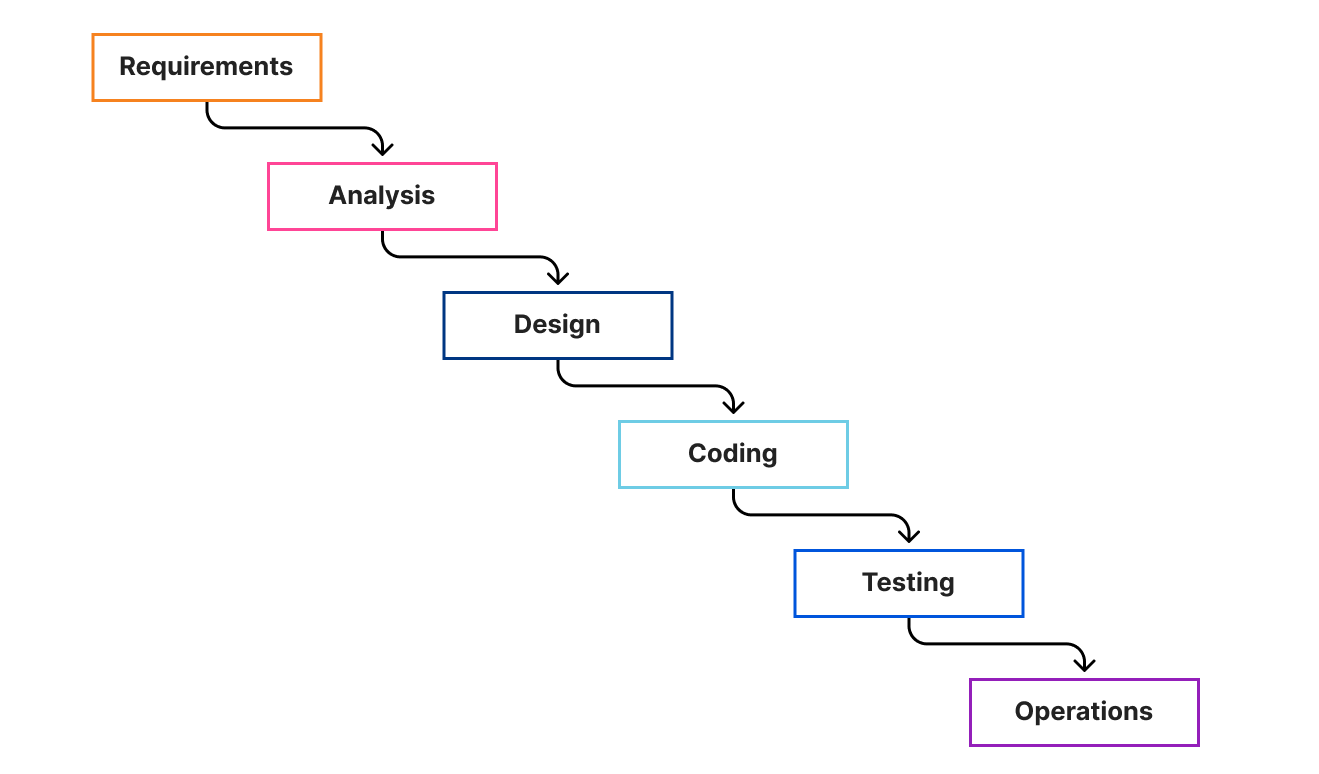
Waterfall has its foundations (pun intended) in construction and manufacturing. It breaks a project up into phases and presumes that each phase is completed before the next begins. Each phase “cascades” into the next bit like a waterfall, hence the name.

How we build software at Cloudflare

The main criticism of waterfall approaches arises when flaws are discovered downstream, which may necessitate a return to earlier phases — though this can be managed through governance processes that allows for adjusting scope, budgets or timelines.

More recently there are a number of modified waterfall models which have been developed as a response to its perceived inflexibility. Some notable examples are the Rational Unified Process (RUP), which encourages iteration within phases, and Sashimi which provides partial overlap between phases.

Despite falling out of favour in recent years, waterfall still has a place in modern technology companies. It tends to be reserved for projects where the scope and requirements can be defined upfront and are unlikely to change. At Cloudflare, we use it for infrastructure rollouts, for example. It also has a place in very large projects with complex dependencies to manage.

Agile Approaches

Agile isn’t a single well-defined process, rather a family of approaches which share similar philosophies — those of the agile manifesto. Implementations vary, but most agile flavours tend to share a number of common traits:

  • Short release cycles, such that regular feedback (ideally from real users) can be incorporated.
  • Teams maintain a prioritized to-do list of upcoming work (often called a ‘backlog’), with the most valuable items are at the top.
  • Teams should be self-organizing, and work at a sustainable pace.
  • A philosophy of Continuous Improvement, where teams seek to improve their ways of working over time.

Continuous improvement is very much the heart of agile, meaning these approaches are less about nailing down “the correct process” and focus more on regular reflection and change. This means variances between any two teams is expected, and encouraged.

Agile approaches can be divided into two main branches — iterative and flow-based. Scrum is probably the most prevalent of the iterative agile methods. In Scrum a team aims to build shippable increments of code at regular intervals called sprints (or “iterations”). Flow-based approaches on the other hand (such as Kanban) instead pick up new items from their backlog on an ad hoc basis. They use a number of techniques to try and minimise work in progress across the team.

The main differences between the two branches can be typified by looking at two example teams:

  • The “Green” Team has a set of products they support and wants to update them regularly, production issues for them are rare and there is very little ad-hoc work. An iterative approach allows them to make long term plans whilst also being able to incorporate feedback from users with some regularity.
  • The “Blue” Team meanwhile is an operational team, where a big part of their role is to monitor production systems and investigate issues as they arise. For them, a flow based approach is much more appropriate, so they can update their plans on the fly as new items arise.

Which approach does Cloudflare follow?

Cloudflare comprises dozens of globally distributed engineering teams each with their own unique challenges and contexts. A team usually has an Engineering Manager, a Product Manager and less than 10 engineers, who all focus on a singular product or mission. The DDoS team for example is one such team.

A team that supports a newly released product will likely want to rapidly incorporate feedback from customers, whereas a team that manages shared internal platforms will prize platform stability over speed of innovation. There is a spectrum of different contexts within Cloudflare which makes it impossible to define a single software delivery method for all teams to follow.

Instead, we take a more nuanced approach where we allow teams to decide which methodology they wish to follow within the team, whilst also defining a number of high-level concepts and language that are common to all teams. In other words, we are more concerned with macro-management than micro-management.

“SHIP”s and “Epic”s

At the highest level, our unit of work is called a “SHIP”  — this is a change to a service or product which we intend to ship to customers, hence the name. All live SHIPs are published on our internal roadmap, called our “SHIP-board”. Transparency and collaboration are part of our DNA at Cloudflare, so for us, it’s important that anyone in Cloudflare can view the SHIP-board.

Individual SHIPs are sized such that they can be comfortably delivered within a month or two, though we have a strong preference towards shorter timescales. We’d much rather deliver three small feature sets monthly than one big launch every quarter.

A single SHIP might need work from multiple teams in order for customers to use it. We manage this by ensuring there is an EPIC within the SHIP for each team contributing. To prevent circular dependencies, a SHIP can’t contain another SHIP. SHIPs are owned by their Product Manager, and EPICs are usually owned by an Engineering Manager. We also allow for EPICs to be created that don’t deliver against SHIPs — this is where technical improvement initiatives are typically managed.

Below the level of EPICs we don’t enforce any strict delivery model on teams, though teams will usually link their contributory work to the EPIC for ease of tracking. Teams are free to use whichever delivery framework they wish.

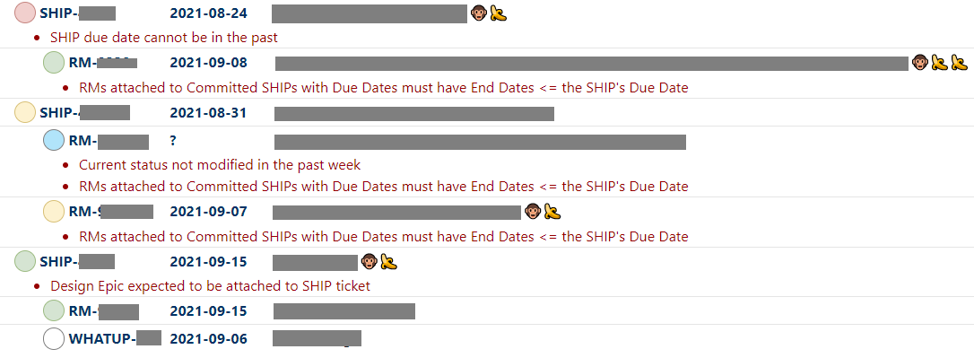
Within the Product Engineering organisation, all Product Managers and Engineering managers meet weekly to discuss progress and blockers of their live SHIPs/EPICs. Due to the number of people involved, this is a very rapid fire meeting facilitated by our automated “SHIP-board”. This has a built-in linter to highlight potential issues, to be updated prior to the meeting. We run through each team one by one, starting with the team with the most outstanding lints.

There’s also a few icons which let us visualise the status of a SHIP or EPIC at a glance. For example, a monkey means the target date for an item moved in the last week. Bananas count the total number of times the date has “slipped”, i.e. changed. A typical fragment of the SHIP-board is shown below.

How we build software at Cloudflare

Planning

Planning takes place every quarter. This lets us deliver aggressively, without having to change plans too frequently. It also forces us to make conscious choices about what to include and exclude from a SHIP so that extraneous work is minimised.

About a month before quarter-end, product managers will begin to compile the SHIPs that would deliver the most value to customers. They’ll work with their engineering teams to understand how the work might be done, and what work is required of other teams (e.g. the UI team might need to build a frontend whilst another team builds the API).

The team will likely estimate the work at this stage (though the exact mechanism is left up to them). Where work is required of other teams we’ll also begin to reach out to them, so they can factor it into their work for the quarter, and estimate their effort too. It’s also important at this stage to understand what kind of dependency this is — do we need one piece to fully complete before the other, or can they be done in parallel and integrated towards the end? Usually the latter.

The final aspect of planned work are unlinked EPICs — these are things that don’t necessarily contribute meaningfully to a SHIP, but the team would still like to get them completed. Examples of this are performance improvements, or changes/fixes to backend tooling.

We deliver continuously through the quarter to avoid a scramble of deployment at once, and our target dates will reflect that. We also allow anything delivered in the first two weeks of the following quarter to still count as being on-time — stability of the network is more important than hitting arbitrary dates.

We also take a fairly pragmatic approach towards target dates. A natural part of software delivery is that as we begin to explore the solution space we may uncover additional complexity. As long as we can justify a change of date it’s perfectly acceptable to amend the dates of SHIPs/EPICs to reflect the latest information. The exception to this is where we’ve made an external commitment to deliver something, so changing the delivery dates is subject to greater scrutiny.

Keeping us safe

You might think that letting teams set their own process might lead to chaos, but in my experience the opposite is true. By allowing teams to define their own methods we are empowering them to make better decisions and understand their own context within Cloudflare. We explicitly define the interfaces we use between teams, and that allows teams the flexibility to do what works best for them.

We don’t go as far as to say “there are no rules”. Last quarter Cloudflare blocked an average of 87 billion cyber threats each day, and in July 2021 we blocked the largest DDoS attack ever recorded. If we have an outage, our customers feel it, and we feel it too. To manage this we have strict, though simple, rules governing how code reaches our data centers. For example, we mandate a minimum number of reviews for each piece of code, and our deployments are phased so that changes are tested on a subset of live traffic, so any issues can be localised.

The main takeaway is to find the right balance between freedom and rules, and appreciate that this may vary for different teams within the organisation. Enforcing an unnecessarily strict process can cause a lot of friction in teams, and that’s a shortcut to losing great people. Our ideal process is one that minimises red tape, such that our team can focus on the hard job of protecting our customers.

P.S. — we’re hiring!

Do you want to come and work on advanced technologies where every code push impacts millions of Internet properties? Join our team!

България ще бъде различна

Post Syndicated from Bozho original https://blog.bozho.net/blog/3855

В последната година и половина в България се промениха много неща. Те не са очевидни в ежедневнието, но са значителни и са важно начало. Ще опитам да дам моя „вътрешен“ поглед на ситуацията и по-важното – какво предстои. Смятам, че има четири етапа не тези промени.

До средата на 2020 г. всичко изглеждаше монотонно и предрешено – ГЕРБ щеше да спечели още един мандат, социологията от май месец даваше сравнително високо доверие за Борисов и кабинета, а на хоризонта нямаше алтернатива. Тогава се случи събитие, което „разбърка“ нещата. Росенец.

На Росенец Христо Иванов и съмишленици осветиха преплитането на власт, икономически и лични интереси; осветиха влиянието и безнаказаността на ДПС и демаскираха зависимостите на ГЕРБ. Тогава написах, че Росенец е начало. И макар в момента много хората да опитват да омаловажат това събитие, мисля, че историците след много години ще го анализират и ще му отдадат необходимата важност.

След Росенец последва неизбежния отговор на президента заради подопечната му НСО, в който той атакува ДПС, Доган и Борисов. Последва и контраатака на зависимата от ДПС прокуратура, която влезе в президентството. Двете събития доведоха до протести, които промениха коренно картината и макар да не свалиха Борисов, предвещаха края на управлението му.

Росенец даде началото на първия етап. Вторият етап започна с парламентарните избори през април. До тях много хора все още не вярваха, че ГЕРБ няма да управлява и че няма да бъде отпусната тяхната хватка над властови и икономически влияния. Но изборният резултат и последващата твърдост на „партиите на протеста“ размагьоса избирателите – вече беше ясно, че ерата „Борисов“ свършва. ГЕРБ се сви до едно ядро избиратели, което е много различно от това, което ги държа на власт толкова време. Изборите дадоха начало на отпускането на властовите инструменти от ГЕРБ и ДПС, доведоха до служебно правителство, което разрови доста схеми, за които медии и опозиция говореха отдавна, но те си продължаваха и се разрастваха.

„Партиите на протеста“ станаха „партии на промяната“, но кабинет така и не беше сформиран. Причините са много, но могат да се обобщят с това, че се беше случила важна промяна в политическия пейзаж – вече нямаше един голям, който да определя условията. Това ще бъде трайната политическа ситуация, с която партиите трябва да свикват – ще има 5-6 средни по големина партии, които трябва да се научат на коалиционна култура, за да може да има управление.

Третият етап започва на 14 ноември. След изборите има шанс партиите на промяната да направят коалиционно управление, което да управлява с експертност и приличие; с прозрачност и отговорност; управление, което да реши затлачвани с години проблеми в правосъдие, образование, здравеопазване, инфраструктура, а и на практика всяка сфера. Такова управление не е гарантирано, а заявките, които ГЕРБ, ДПС и БСП дадоха в края на предния парламент за съвместни действия, продължени от действията на техните представители в ЦИК в тази предизборна кампания, са плашеща алтернатива – „още от същото, но дори по-грозно“.

Ако това не се случи и все пак партиите на промяната постигнат достатъчно висок резултат, в средносрочен план предстои четвъртата стъпка – промяна на мисленето. Мисленето, че сме аутсайдери, че нищо не зависи от нас, че е окей да сме последни, че е нормално всичко да е корумпирано. Да спрем да се дърпаме надолу в казана. Да водим, а не да догонваме.

Смятам, че последните година и половина и следващите две-три години са от историческа важност за България. И затова влагам усилията си в политическа кауза, каквато е Да, България и Демократична България. При всички рискове и негативи от това. България ще излезе различна от този период и зависи от всеки едни от нас да е към по-добро.

Материалът България ще бъде различна е публикуван за пръв път на БЛОГодаря.

Cat Lamin on building a global educator family | Hello World #17

Post Syndicated from Gemma Coleman original https://www.raspberrypi.org/blog/global-staffroom-mental-health-hello-world-17/

Cat Lamin.

In Hello World issue 17, Raspberry Pi Certified Educator Cat Lamin talks about how building connections and sharing the burden can help make us better educators, even in times of great stress:

“I felt like I needed to play my part”

In March 2020, the world suddenly changed. For educators, we jumped from face-to-face teaching to a stark new landscape, with no idea of how the future would look. As generous teachers pushed out free resources, I felt like I needed to play my part. Suddenly, an idea struck me. In September 2017, I had decided to be brave and submit a talk to PyConUK to discuss my mental health. Afterwards, several people in the audience shared their own stories with me or let me know that it helped them just to hear that someone else struggled too. I realised that in times of pressure, we need a chance to talk and we had lost these outlets. In school, we would pop to the staffroom or a friend’s classroom for a quick vent, but that wasn’t an option anymore. People were feeling isolated, scared, stressed and didn’t have anyone to turn to.

I realised that in times of pressure, we need a chance to talk, and we had lost these outlets.

Cat Lamin

Thus, the first Global Google Educator Group Staffroom: Mental Health Matters was launched on 14 March 2020, which coincided with the US government announcing school closures and UK teachers still waiting anxiously to hear when doors would close. The aim of Staffroom was to give teachers a safe space to talk about how they’re feeling under the overwhelming weight of school closures. To say it was a success would be an understatement, with teachers joining the calls from Australia, Malaysia, the USA, Colombia, Mexico, Brazil, Europe and more!

Pily Perfil.

“Staffroom for me is a place and time to connect with other teachers from around the world. I remember seeing the calendar invites by mail and I kept thinking I should join but was afraid to do it. The first time I did it, I listened first and it made me realize that my struggles during pandemic online teaching were the same struggles as everywhere else.” – Pily Hernandez, Monterrey, Mexico

Which William are you today?

In those early days, we just gave teachers a chance to talk. The format of our meetings was simple: what’s your name, where are you from, and then an ice breaker question like ‘What colour do you feel like?’ or ‘What song represents your current mood?’ It wasn’t long before we hit upon a winning formula by making our own ‘Which image are you today?’ picture scale (see the ‘Which William’ image below!). Using the picture scales allowed people to really express how they felt. Often someone who had been happily chatting would explain that they were actually struggling to keep their head above water because a silly image allowed them to be honest.

A grid of photos of the same toddler expressing different emotions.
Which William are you today?

One of the most important messages from Staffroom was that many people involved with technology in schools were feeling alone. After years of suggesting teachers use technology, suddenly they were blamed for schools not being properly prepared. They were struggling with not necessarily knowing what to suggest to teachers with technology difficulties, as they were grappling with their own personal lockdown situations. Hearing that other people, all around the world, were experiencing something similar was hugely eye-opening and took a great amount of weight off their shoulders.

Abid Patel.

“As someone who thrived from having in person connections and networking opportunities, lockdown hit me hard. Staffroom really helped to keep those connections going and has developed into such a lovely safe space to talk and connect with others.” – Abid Patel, London, UK

We varied the tone of the sessions depending on the needs of the attendees. In the first few months, we shared our lockdown situations and our different experiences across the world. We could share advice and tips, as well as best practice for delivering content and things that had gone terribly wrong since switching to remote teaching. Or we’d discuss food in different countries around the world (did you know that in Australia, fish and chips is made from shark?) or joke about whether Vegemite was actually an edible product (it’s ok, I tried it live on camera during one Staffroom). Other days, we would discuss how difficult we were finding teaching, isolation or life in general during a pandemic.

An honest environment

One of the things that people continuously mentioned was that Staffroom was a safe place where they felt they could share, be listened to, and be understood. We made it clear that no one had to speak unless they wanted to. I made a point of always being completely honest about my own mental health. As a person who had suffered from depression and anxiety in the past, it was no surprise to me when I was diagnosed with both near the end of 2020, and I was fortunate enough to get virtual therapy. I shared my story with the group, which allowed attendees to feel more comfortable being open and talking about their own struggles, in some cases leading to their own diagnosis and getting much-needed support.

Frederick Ballew.

“Staffroom has been the best ‘out of my comfort zone’ leap that I have ever taken. I have met educators from all over the world and learned that there are more things that unite us than divide us in this world of education.” – Frederick Ballew, Minnesota, USA

People would join Staffroom to share new jobs, engagements, even cross-country moves, but equally they would join after losing a loved one or hearing of a pupil sick in hospital. Staffroom became a safe haven for teachers, coaches, IT directors, and pretty much anyone involved in technology within education. It is a place where we could bond over shared experience, share a joke, ask questions, get ideas, and even plan our futures.

Do not underestimate the power of connections, and of sharing your story.

Cat Lamin

Alongside Staffroom, I also built a website to allow teachers to share their mental health stories and to feel a little less alone (mentalhealthineducation.com). I continue to host regular Staffrooms, although less frequently. 18 months ago, we needed a chance to talk three times a week, but now we meet two or three times a month instead. You can find current Staffroom dates at www.globalgeg.org/events. If you take one thing away from this article, however, it is this: do not underestimate the power of connections, and of sharing your story.

Cat Lamin is a Raspberry Pi Certified Educator, CAS Master Teacher, and Google Certified Innovator who works as a freelance trainer and coach, supporting schools with digital strategy and enabling educators to use technology more effectively. For running this regular mental health staffroom, she was awarded a Mental Health Champion Award from Edufuturist.

Share your thoughts about Hello World with me!

Your insights are invaluable to help us make Hello World as useful as it can be for computing educators around the globe. Hello World is a magazine for educators from educators — so if you are interested in having a 20-minute chat with me about what you like about the magazine, and what you would like to change, then please sign up here. I look forward to speaking with you.

Download Hello World for free

The brand-new issue of our free Hello World magazine for computing educators focuses on all things health and well-being.

Cover of issue 17 of Hello World.

It is full of inspiring stories and practical ideas for teaching your learners about computing in this context, and supporting them to use digital technologies in beneficial ways.

Download the new issue of Hello World for free today:

To never miss a new issue, you can subscribe to Hello World for free. Also check out the first-ever special edition of Hello World, The Big Book of Pedagogy. It focuses on approaches to teaching computing in the classroom, and you can download the special edition for free.

Wherever you are in the world, you can listen to our Hello World podcast too! Each episode, we explore a new topic with some of the computing educators who’ve written for the magazine.

The post Cat Lamin on building a global educator family | Hello World #17 appeared first on Raspberry Pi.

Deep Dive on Amazon EC2 VT1 Instances

Post Syndicated from Rick Armstrong original https://aws.amazon.com/blogs/compute/deep-dive-on-amazon-ec2-vt1-instances/

This post is written by:  Amr Ragab, Senior Solutions Architect; Bryan Samis, Principal Elemental SSA; Leif Reinert, Senior Product Manager

Introduction

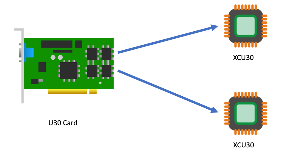
We at AWS are excited to announce that new Amazon Elastic Compute Cloud (Amazon EC2) VT1 instances are now generally available in the US-East (N. Virginia), US-West (Oregon), Europe (Ireland), and Asia Pacific (Tokyo) Regions. This instance family provides dedicated video transcoding hardware in Amazon EC2 and offers up to 30% lower cost per stream as compared to G4dn GPU based instances or 60% lower cost per stream as compared to C5 CPU based instances. These instances are powered by Xilinx Alveo U30 media accelerators with up to eight U30 media accelerators per instance in the vt1.24xlarge. Each U30 accelerator comes with two XCU30 Zynq UltraScale+ SoCs, totaling 16 addressable devices in the vt1.24xlarge instance with H.264/H.265 Video Codec Units (VCU) cores.

Each U30 accelerator card comes with two XCU30 Zynq UltraScale+ SoCs

Currently, the VT1 family consists of three sizes, as summarized in the following:

Instance Type vCPUs RAM U30 accelerator cards Addressable XCU30 SoCs 
vt1.3xlarge 12 24 1 2
vt1.6xlarge 24 48 2 8
vt1.24xlarge 96 182 8 16

Each addressable XCU30 SoC device supports:

  • Codec: MPEG4 Part 10 H.264, MPEG-H Part 2 HEVC H.265
  • Resolutions: 128×128 to 3840×2160
  • Flexible rate control: Constant Bitrate (CBR), Variable Bitrate(VBR), and Constant Quantization Parameter(QP)
  • Frame Scan Types: Progressive H.264/H.265
  • Input Color Space: YCbCr 4:2:0, 8-bit per color channel.

The following table outlines the number of transcoding streams per addressable device and instance type:

Transcoding Each XCU30 SoC vt1.3xlarge vt1.6xlarge vt1.24xlarge
3840x2160p60 1 2 4 16
3840x2160p30 2 4 8 32
1920x1080p60 4 8 16 64
1920x1080p30 8 16 32 128
1280x720p30 16 32 64 256
960x540p30 24 48 92 384

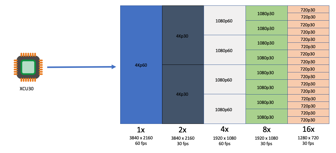
Each XCU30 SoC can support the following stream densities: 1x 4kp60, 2x 4kp30, 4x 1080p60, 8x 1080p30, 16x 720p30

Customers with applications such as live broadcast, video conferencing and just-in-time transcoding can now benefit from a dedicated instance family devoted to video encoding and decoding with rescaling optimizations at the lowest cost per stream. This dedicated instance family lets customers run batch, real-time, and faster than real-time transcoding workloads.

Deployment and Quick Start

To get started, you launch a VT1 instance with prebuilt VT1 Amazon Machine Images (AMIs), available on the AWS Marketplace. However, if you have AMI hardening requirements or other requirements that require you to install the Xilinx software stack, you can reference the Xilinx Video SDK documentation for VT1.

The software stack utilizes a driver suite that is a combination of the driver stack as well as management and client tools. The following terminology will be used in this instance family:

  • XRT – Xilinx Runtime Library
  • XRM – Xilinx Runtime Management Library
  • XCDR – Xilinx Video Transcoding SDK
  • XMA – Xilinx Media Accelerator API and Samples
  • XOCL – Xilinx driver (xocl)

To run workloads directly on Amazon EC2 instances, you must load both the XRT and XRM stack. These are conveniently provided by loading the XCDR environment. To load the devices, run the following:

source /opt/xilinx/xcdr/setup.sh

With the output:

-----Source Xilinx U30 setup files-----
XILINX_XRT        : /opt/xilinx/xrt
PATH              : /opt/xilinx/xrt/bin:/usr/local/sbin:/sbin:/bin:/usr/sbin:/usr/bin:/root/bin
LD_LIBRARY_PATH   : /opt/xilinx/xrt/lib:
PYTHONPATH        : /opt/xilinx/xrt/python:
XILINX_XRM      : /opt/xilinx/xrm
PATH            : /opt/xilinx/xrm/bin:/opt/xilinx/xrt/bin:/usr/local/sbin:/sbin:/bin:/usr/sbin:/usr/bin:/root/bin
LD_LIBRARY_PATH : /opt/xilinx/xrm/lib:/opt/xilinx/xrt/lib:
Number of U30 devices found : 16  

Running Containerized Workloads on Amazon ECS and Amazon EKS

To help build AMIs for Amazon Linux2, Ubuntu 18/20, Amazon ECS and Amazon Elastic Kubernetes Service (Amazon EKS), we have provided a Github project in order to simplify the build process utilizing Packer:

https://github.com/aws-samples/aws-vt-baseami-pipeline

At the time of writing, Xilinx does not have an officially supported container runtime. However, it is possible to pass the specific devices in the docker run ... stanza, and in order to set this environment download this specific script. The following example is the output for vt1.24xlarge:

[ec2-user@ip-10-0-254-236 ~]$ source xilinx_aws_docker_setup.sh
XILINX_XRT : /opt/xilinx/xrt
PATH : /opt/xilinx/xrt/bin:/usr/local/bin:/usr/bin:/usr/local/sbin:/usr/sbin:/home/ec2-user/.local/bin:/home/ec2-user/bin
LD_LIBRARY_PATH  : /opt/xilinx/xrt/lib:
PYTHONPATH : /opt/xilinx/xrt/python:
XILINX_AWS_DOCKER_DEVICES : --device=/dev/dri/renderD128:/dev/dri/renderD128
--device=/dev/dri/renderD129:/dev/dri/renderD129
--device=/dev/dri/renderD130:/dev/dri/renderD130
--device=/dev/dri/renderD131:/dev/dri/renderD131
--device=/dev/dri/renderD132:/dev/dri/renderD132
--device=/dev/dri/renderD133:/dev/dri/renderD133
--device=/dev/dri/renderD134:/dev/dri/renderD134
--device=/dev/dri/renderD135:/dev/dri/renderD135
--device=/dev/dri/renderD136:/dev/dri/renderD136
--device=/dev/dri/renderD137:/dev/dri/renderD137
--device=/dev/dri/renderD138:/dev/dri/renderD138
--device=/dev/dri/renderD139:/dev/dri/renderD139
--device=/dev/dri/renderD140:/dev/dri/renderD140
--device=/dev/dri/renderD141:/dev/dri/renderD141
--device=/dev/dri/renderD142:/dev/dri/renderD142
--device=/dev/dri/renderD143:/dev/dri/renderD143
--mount type=bind,source=/sys/bus/pci/devices/0000:00:1d.0,target=/sys/bus/pci/devices/0000:00:1d.0 --mount type=bind,source=/sys/bus/pci/devices/0000:00:1e.0,target=/sys/bus/pci/devices/0000:00:1e.0

Once the devices have been enumerated, start the workload by running:

docker run -it $XILINX_AWS_DOCKER_DEVICES <image:tag>

Amazon EKS Setup

To launch an EKS cluster with VT1 instances, create the AMI from the scripts provided in the repo earlier.

https://github.com/aws-samples/aws-vt-baseami-pipeline

Once the AMI is created, launch an EKS cluster:

eksctl create cluster --region us-east-1 --without-nodegroup --version 1.19 \
       --zones us-east-1c,us-east-1d

Once the cluster is created, substitute the values for the cluster name, subnets, and AMI IDs in the following template.

apiVersion: eksctl.io/v1alpha5
kind: ClusterConfig

metadata:
  name: <cluster-name>
  region: us-east-1

vpc:
  id: vpc-285eb355
  subnets:
    public:
      endpoint-one:
        id: subnet-5163b237
      endpoint-two:
        id: subnet-baff22e5

managedNodeGroups:
  - name: vt1-ng-1d
    instanceType: vt1.3xlarge
    volumeSize: 200
    instancePrefix: vt1-ng-1d-worker
    ami: <ami-id>
    iam:
      withAddonPolicies:
        imageBuilder: true
        autoScaler: true
        ebs: true
        fsx: true
        cloudWatch: true
    ssh:
      allow: true
      publicKeyName: amrragab-aws
    subnets:
    - endpoint-one
    minSize: 1
    desiredCapacity: 1
    maxSize: 4
    overrideBootstrapCommand: |
      #!/bin/bash
      /etc/eks/bootstrap.sh <cluster-name>

Save this file, and then deploy the nodegroup.

eksctl create nodegroup -f vt1-managed-ng.yaml

Once deployed, apply the FPGA U30 device plugin. The daemonset container is available on the Amazon Elastic Container Registry (ECR) public gallery. You can also access the daemonset deployment file.

kubectl apply -f xilinx-device-plugin.yml

Confirm that the Xilinx U30 device(s) are seen by K8s API server and can be allocatable in your job.

Capacity:
  attachable-volumes-aws-ebs:                  39
  cpu:                                         12
  ephemeral-storage:                           209702892Ki
  hugepages-1Gi:                               0
  hugepages-2Mi:                               0
  memory:                                      23079768Ki
  pods:                                        15
  xilinx.com/fpga-xilinx_u30_gen3x4_base_1-0:  1
Allocatable:
  attachable-volumes-aws-ebs:                  39
  cpu:                                         11900m
  ephemeral-storage:                           192188443124
  hugepages-1Gi:                               0
  hugepages-2Mi:                               0
  memory:                                      22547288Ki
  pods:                                        15
  xilinx.com/fpga-xilinx_u30_gen3x4_base_1-0:  1

Video Quality Analysis

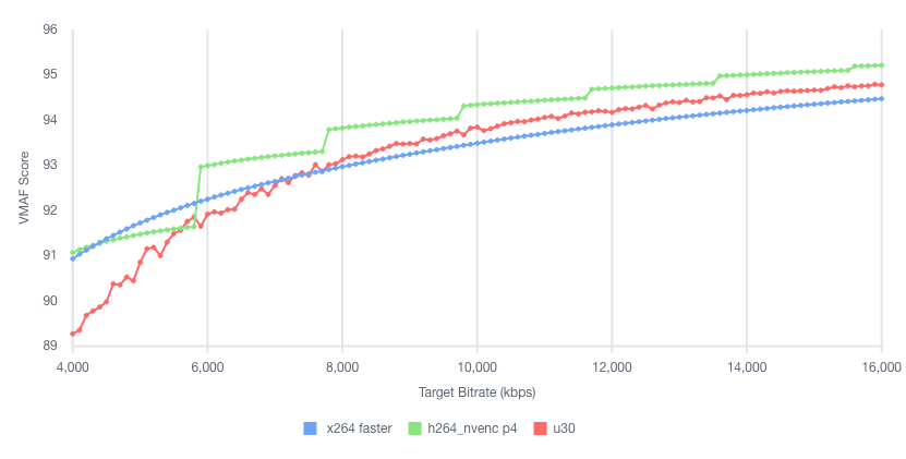
The video quality produced by the U30 is roughly equivalent to the “faster” profile in the x264 and x265 codecs, or the “p4” preset using the nvenc codec on G4dn. For example, in the following test we encoded the same UHD (4K) video at multiple bitrates into H264, and then compared Video Multimethod Assessment Fusion (VMAF) scores:

Plotting VMAF and bitrate we see comparable quality across x264 faster, h264_nvenc p4 and u30

Stream Density and Encoding Performance

To illustrate the VT1 instance family stream density and encoding performance, let’s look at the smallest instance, the vt1.3xlarge, which can encode up to eight simultaneous 1080p60 streams into H.264. We chose a set of similar instances at a close price point, and then compared how many 1080p60 H264 streams they could encode simultaneously to an equivalent quality:

Column 1 Column 2 Column 3 Column 4 Column 5
Instance Codec us-east-1 Hourly Price* 1080p60 Streams / Instance Hourly Cost / Stream
c5.4xlarge x264 $0.680 2 $0.340
c6g.4xlarge x264 $0.544 2 $0.272
c5a.4xlarge x264 $0.616 3 $0.205
g4dn.xlarge nvenc $0.526 4 $0.132
vt1.3xlarge xma $0.650 8 $0.081

* Prices accurate as of the publishing date of this article.

As you can see, the vt1.3xlarge instance can encode four times as many streams as the c5.4xlarge, and at a lower hourly cost. It can also encode two times the number of streams as a g4dn.xlarge instance. Thus, yielding in this example a cost per stream reduction of up to 76% over c5.4xlarge, and up to 39% compared to g4dn.xlarge.

Faster than Real-time Transcoding

In addition to encoding multiple live streams in parallel, VT1 instances can also be utilized to encode file-based content at faster-than-real-time performance. This can be done by over-provisioning resources on a single XCU30 device so that more resources are dedicated to transcoding than are necessary to maintain real-time.

For example, running the following command (specifying -cores 4) will utilize all resources on a single XCU30 device, and yield an encode speed of approximately 177 FPS, or 2.95 times faster than real-time for a 60 FPS source:

$ ffmpeg -c:v mpsoc_vcu_h264 -i input_1920x1080p60_H264_8Mbps_AAC_Stereo.mp4 -f mp4 -b:v 5M -c:v mpsoc_vcu_h264 -cores 4 -slices 4 -y /tmp/out.mp4
frame=43092 fps=177 q=-0.0 Lsize= 402721kB time=00:11:58.92 bitrate=4588.9kbits/s speed=2.95x

To maximize FPS further, utilize the “split and stitch” operation to break the input file into segments, and then transcode those in parallel across multiple XCU30 chips or even multiple U30 cards in an instance. Then, recombine the file at the output. For more information, see the Xilinx Video SDK documentation on Faster than Real-time transcoding.

Using the provided example script on the same 12-minute source file as the preceding example on a vt1.3xlarge, we can utilize both addressable devices on the U30 card at once in order to yield an effective encode speed of 512 fps, or 8.5 times faster than real-time.

$ python3 13_ffmpeg_transcode_only_split_stitch.py -s input_1920x1080p60_H264_8Mbps_AAC_Stereo.mp4 -d /tmp/out.mp4 -i h264 -o h264 -b 5.0

There are 1 cards, 2 chips in the system
...
Time from start to completion : 84 seconds (1 minute and 24 seconds)
This clip was processed 8.5 times faster than realtime

This clip was effectively processed at 512.34 FPS

Conclusion

We are excited to launch VT1, our first EC2 instance with dedicated hardware acceleration for video transcoding, which provides up to 30% lower cost per stream as compared to G4dn or 60% lower cost per stream as compared to G5. With up to eight Xilinx Alveo U30 media accelerators, you can parallelize up to 16 4K UHD streams, for batch, real-time, and faster than real-time transcoding. If you have any questions, reach out to your account team. Now, go power up your video transcoding workloads with Amazon EC2 VT1 instances.

Folios merged for 5.16

Post Syndicated from original https://lwn.net/Articles/874684/rss

The long-running and sometimes acrimonious discussion on the memory folio patch set has come to an end:
the folio patches were the first thing pulled into the mainline repository
for the 5.16 development cycle. Now the developers involved just have to
do all of the other work identified as necessary to clean up the
memory-management subsystem and isolate it from other parts of the kernel.

Building ARM64 applications on AWS Graviton2 using the AWS CDK and Self-Hosted Runners for GitHub Actions

Post Syndicated from Rick Armstrong original https://aws.amazon.com/blogs/compute/building-arm64-applications-on-aws-graviton2-using-the-aws-cdk-and-self-hosted-runners-for-github-actions/

This post is written by Frank Dallezotte, Sr. Technical Account Manager, and Maxwell Moon, Sr. Solutions Architect

AWS Graviton2 processors are custom built by AWS using the 64-bit Arm Neoverse cores to deliver great price performance for workloads running in Amazon Elastic Compute Cloud (Amazon EC2). These instances are powered by 64 physical core AWS Graviton2 processors utilizing 64-bit Arm Neoverse N1 cores and custom silicon designed by AWS, built using advanced 7-nanometer manufacturing technology.

Customers are migrating their applications to AWS Graviton2 based instance families in order to take advantage of up to 40% better price performance over comparable current generation x86-based instances for a broad spectrum of workloads. This migration includes updating continuous integration and continuous deployment (CI/CD) pipelines in order to build applications for ARM64.

One option for running CI/CD workflows is GitHub Actions, a GitHub product that lets you automate tasks within your software development lifecycle. Customers utilizing GitHub Actions today can host their own runners and customize the environment used to run jobs in GitHub Actions workflows, allowing you to build ARM64 applications. GitHub recommends that you only use self-hosted runners with private repositories.

This post will teach you to set up an AWS Graviton2 instance as a self-hosted runner for GitHub Actions. We will verify the runner is added to the default runner group for a GitHub Organization, which can only be used by private repositories by default. Then, we’ll walk through setting up a continuous integration workflow in GitHub Actions that runs on the self-hosted Graviton2 runner and hosted x86 runners.

Overview

This post will cover the following:

  • Network configurations for deploying a self-hosted runner on EC2.
  • Generating a GitHub token for a GitHub organization, and then storing the token and organization URL in AWS Systems Manager Parameter Store.
  • Configuring a self-hosted GitHub runner on EC2.
  • Deploying the network and EC2 resources by using the AWS Cloud Development Kit (AWS CDK).
  • Adding Graviton2 self-hosted runners to a workflow for GitHub Actions to an example Python application.
  • Running the workflow.

Prerequisites

  1. An AWS account with permissions to create the necessary resources.
  2. A GitHub account: This post assumes that you have the required permissions as a GitHub organization admin to configure your GitHub organization, as well as create workflows.
  3. Familiarity with the AWS Command Line Interface (AWS CLI).
  4. Access to AWS CloudShell.
  5. Access to an AWS account with administrator or PowerUser (or equivalent) AWS Identity and Access Management (IAM) role policies attached.
  6. Account capacity for two Elastic IPs for the NAT gateways.
  7. An IPv4 CIDR block for a new Virtual Private Cloud (VPC) that is created as part of the AWS CDK stack.

Security

We’ll be adding the self-hosted runner at the GitHub organization level. This makes the runner available for use by the private repositories belonging to the GitHub organization. When new runners are created for an organization, they are automatically assigned to the default self-hosted runner group, which, by default, cannot be utilized by public repositories.

You can verify that your self-hosted runner group is only available to private repositories by navigating to the Actions section of your GitHub Organization’s settings. Select the “Runner Groups” submenu then the Default runner group and confirm that “Allow public repositories” is not checked.

GitHub recommends only utilizing self-hosted runners with private repositories. Allowing self-hosted runners on public repositories and allowing workflows on public forks introduces a significant security risk. More information about the risks can be found in self-hosted runner security with public repositories.

In this post, we verified that for the default runner group, allowing public repositories is not enabled.

AWS CDK

To model and deploy our architecture, we use the AWS CDK. The AWS CDK lets us design components for a self-hosted runner that are customizable and shareable in several popular programming languages.

Our AWS CDK application is defined by two stacks (VPC and EC2) that we’ll use to create the networking resources and our self-hosted runner on EC2.

Network Configuration

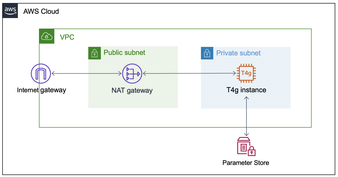
This section will walk through the networking resources that the CDK stack will create in order to support this architecture. We are deploying our self-hosted runner in a private subnet. A NAT gateway in a public subnet lets the runner make requests to GitHub, but not direct access to the instance from the internet.

  • Virtual Private Cloud – Defines a VPC across two Availability Zones with an IPv4 CIDR block that you set.
  • Public Subnet – A NAT Gateway will be created in each public subnet for outbound traffic through the VPC’s internet gateway.
  • Private Subnet – Contains the EC2 instance for the self-hosted runner that routes internet bound traffic through a NAT gateway in the public subnet.

AWS architecture diagram for self-hosted runner.

Configuring the GitHub Runner on EC2

To successfully provision the instance, we must  supply the GitHub organization URL and token. To accomplish this, we’ll create two AWS Systems Manager Parameter Store values (gh-url and gh-token), which will be accessed via the EC2 instance user data script when the CDK application deploys the EC2 stack. The EC2 instance will only be accessible through AWS Systems Manager Session Manager.

Get a Token From GitHub

The following steps are based on these instructions for adding self-hosted runners – GitHub Docs.

  1. Navigate to the private GitHub organization where you’d like to configure a custom GitHub Action Runner.
  2. Under your repository name, organization, or enterprise, click Settings.
  3. In the left sidebar, click Actions, then click Runners.
  4. Under “Runners”, click Add runner.
  5. Copy the token value under the “Configure” section.

NOTE: this is an automatically generated time-limited token for authenticating the request.

Create the AWS Systems Manager Parameter Store Values

Next, launch an AWS CloudShell environment, and then create the following AWS Systems Manager Parameter Store values in the AWS account where you’ll be deploying the AWS CDK stack.

The names gh-url and gh-token, and types String and SecureString, respectively, are required for this integration:

#!/bin/bash
aws ssm put-parameter --name gh-token --type SecureString --value ABCDEFGHIJKLMNOPQRSTUVWXYZABC
aws ssm put-parameter --name gh-url --type String --value https://github.com/your-url

Self-Hosted Runner Configuration

The EC2 instance user data script will install all required packages, and it will register the GitHub Runner application using the gh-url and gh-token parameters from the AWS Systems Manager Parameter Store. These parameters are stored as variables (TOKEN and REPO) in order to configure the runner.

This script runs automatically when the EC2 instance is launched, and it is included in the GitHub repository. We’ll utilize Amazon Linux 2 for the operating system on the runner instance.

#!/bin/bash
yum update -y
# Download and build a recent version of International Components for Unicode.
# https://github.com/actions/runner/issues/629
# https://github.com/dotnet/core/blob/main/Documentation/linux-prereqs.md
# Install jq for parsing parameter store
yum install -y libicu60 jq
# Get the latest runner version
VERSION_FULL=$(curl -s https://api.github.com/repos/actions/runner/releases/latest | jq -r .tag_name)
RUNNER_VERSION="${VERSION_FULL:1}"


# Create a folder
mkdir /home/ec2-user/actions-runner && cd /home/ec2-user/actions-runner || exit
# Download the latest runner package
curl -o actions-runner-linux-arm64-${RUNNER_VERSION}.tar.gz -L https://GitHub.com/actions/runner/releases/download/v${RUNNER_VERSION}/actions-runner-linux-arm64-${RUNNER_VERSION}.tar.gz
# Extract the installer
tar xzf ./actions-runner-linux-arm64-${RUNNER_VERSION}.tar.gz
chown -R ec2-user /home/ec2-user/actions-runner
REGION=$(curl -s http://169.254.169.254/latest/meta-data/placement/region)
INSTANCE_ID=$(curl -s http://169.254.169.254/latest/meta-data/instance-id)
TOKEN=$(aws ssm get-parameter --region "${REGION}" --name gh-token --with-decryption | jq -r '.Parameter.Value')
REPO=$(aws ssm get-parameter --region "${REGION}" --name gh-url | jq -r '.Parameter.Value')
sudo -i -u ec2-user bash << EOF
/home/ec2-user/actions-runner/config.sh --url "${REPO}" --token "${TOKEN}" --name gh-g2-runner-"${INSTANCE_ID}" --work /home/ec2-user/actions-runner --unattended
EOF
./svc.sh install
./svc.sh start

Deploying the Network Resources and Self-Hosted Runner

In this section, we’ll deploy the network resources and EC2 instance for the self-hosted GitHub runner using the AWS CDK.

From the same CloudShell environment, run the following commands in order to deploy the AWS CDK application:

#!/bin/bash
sudo npm install aws-cdk -g
git clone https://github.com/aws-samples/cdk-graviton2-gh-sh-runner.git
cd cdk-graviton2-gh-sh-runner
python3 -m venv .venv
source .venv/bin/activate
python -m pip install -r requirements.txt
export VPC_CIDR="192.168.0.0/24" # Set your CIDR here.
export AWS_ACCOUNT=`aws sts get-caller-identity | jq -r '.Account'`
cdk bootstrap aws://$AWS_ACCOUNT/$AWS_REGION
cdk deploy --all
# Note: Before the EC2 stack deploys you will be prompted for approval
# The message states 'This deployment will make potentially sensitive changes according to your current security approval level (--require-approval broadening).' and prompts for y/n

These steps will deploy an EC2 instance self-hosted runner that is added to your GitHub organization (as previously specified by the gh-url parameter). Confirm the self-hosted runner has been successfully added to your organization by navigating to the Settings tab for your GitHub organization, selecting the Actions options from the left-hand panel, and then selecting Runners.

Default runner group including an ARM64 self-hosted runner.

Extending a Workflow to use the self-hosted Runner

This section will walk through setting up a GitHub Actions workflow to extend a test pipeline for an example application. We’ll define a workflow that runs a series of static code checks and unit tests on both x86 and ARM.

Our example application is an online bookstore where users can find books, add them to their cart, and create orders. The application is written in Python using the Flask framework, and it uses Amazon DynamoDB for data storage.

Actions expect the workflow to be defined in the folder .github/workflows and the extension of either .yaml or .yml. We’ll create the directory, as well as an empty file inside the directory called main.yml.

#!/bin/bash
mkdir -p .github/workflows
touch .github/workflows/main.yml

First, we must define when our workflow will run. We’ll define the workflow to run when pull requests are created, synchronized (new commits are pushed), or re-opened, and then on push to the main branch.

# main.yml
on:
  pull_request:
    types: [opened, synchronize, reopened]
  push:
    branches:
      - main

Next, define the workflow by adding jobs. Each job can have one or more steps to run. A step defines a command, set up task, or action that will be run. You can also create custom Actions with user-defined steps and repeatable modules.

Next, we’ll define a single job test to include every step of our workflow, as well as a strategy for the job to run the workflow on both x86 and the Graviton2 self-hosted runner. We’ll specify both ubuntu-latest, a hosted runner, and self-hosted for our Graviton2 runner. This lets our workflow run in parallel on two different CPUs, and it is not disruptive of existing processes.

# main.yml
jobs:
  test:
    runs-on: ${{ matrix.os }}
    strategy:
      fail-fast: false
      matrix:
        os: [ubuntu-latest, self-hosted]

Now we can add steps that each runner will run. We’ll be using custom Actions that we create for each step, as well as the pre-built action checkout for pulling down the latest changes to each runner.

GitHub Actions expects all custom actions to be defined in .github/actions/<name of action>/action.yml. We’ll define four custom Actions – check_system_deps, check_and_install_app_deps, run_static_checks, and run_unit_tests.

#!/bin/bash
for action in check_system_deps check_and_install_app_deps run_static_checks run_unit_tests; do \
    mkdir -p .github/actions/${action} && \
    touch .github/actions/${action}/action.yml; \
    done

We define an Action with a series of steps to ensure that the runner is prepared to run our tests and checks:

  1. Check that Python3 is installed
  2. Check that pipenv is installed

Our using statement specifies “composite” to run all steps as a single action.

# .github/actions/check_system_deps/action.yml
name: "Check System Deps"
description: "Check for Python 3.x, list version, Install pipenv if it is not installed"
runs:
  using: "composite"
  steps:
    - name: Check For Python3.x
      run: |
        which python3
        VERSION=$(python3 --version | cut -d ' ' -f 2)
        VERSION_PATCH=$(echo ${VERSION} | cut -d '.' -f 2)
        [ $VERSION_PATCH -ge 8 ]
      shell: bash
    - name: Install Pipenv
      run: python3 -m pip install pipenv --user
      shell: bash

Now that we have the correct version of Python and a package manager installed, we’ll create an action to install our application dependencies:

# .github/actions/check_and_install_app_deps/action.yml
name: "Install deps"
description: "Install application dependencies"
runs:
  using: "composite"
  steps:
    - name: Install deps
      run: python3 -m pipenv install --dev
      shell: bash

Next, we’ll create an action to run all of our static checks. For our example application, we want to perform the following checks:

  1. Check for security vulnerabilities using Bandit
  2. Check the cyclomatic complexity using McCabe
  3. Check for code that has no references using Vulture
  4. Perform a static type check using MyPy
  5. Check for open CVEs in dependencies using Safety
# .github/actions/run_static_checks/action.yml
name: "Run Static Checks"
description: "Run static checks for the python app"
runs:
  using: "composite"
  steps:
    - name: Check common sense security issues
      run: python3 -m pipenv run bandit -r graviton2_gh_runner_flask_app/
      shell: bash
    - name: Check Cyclomatic Complexity
      run: python3 -m pipenv run flake8 --max-complexity 10 graviton2_gh_runner_flask_app
      shell: bash
    - name: Check for dead code
      run: python3 -m pipenv run vulture graviton2_gh_runner_flask_app --min-confidence 100
      shell: bash
    - name: Check static types
      run: python3 -m pipenv run mypy graviton2_gh_runner_flask_app
      shell: bash
    - name: Check for CVEs
      run: python3 -m pipenv check
      shell: bash

We’ll create an action to run the unit tests using PyTest.

# .github/actions/run_unit_tests/action.yml
name: "Run Unit Tests"
description: "Run unit tests for python app"
runs:
  using: "composite"
  steps:
    - name: Run PyTest
      run: python3 -m pipenv run pytest -sv tests
      shell: bash

Finally, we’ll bring all of these actions into our steps in main.yml in order to define every step that will be run on each runner any time that our workflow is run.

# main.yml
steps:
   - name: Checkout Code
     uses: actions/checkout@v2
   - name: Check System Deps
     uses: ./.github/actions/check_system_deps
   - name: Install deps
     uses: ./.github/actions/check_and_install_app_deps
   - name: Run Static Checks
     uses: ./.github/actions/run_static_checks
   - name: Run PyTest
     uses: ./.github/actions/run_unit_tests

Save the file.

Running the Workflow

The workflow will run on the runners when you commit and push your changes. To demonstrate, we’ll create a PR to update the README of our example app in order to kick off the workflow.

After the change is pushed, see the status of your workflow by navigating to your repository in the browser. Select the Actions tab. Select your workflow run from the list of All Workflows. This opens the Summary page for the workflow run.

Successful run of jobs on hosted Ubuntu and self-hosted ARM64 runners.

As each step defined in the workflow job runs, view their details by clicking the job name on the left-hand panel or on the graph representation. The following images are screenshots of the jobs, and example outputs of each step. First, we have check_system_deps.

Successful run of a custom action checking for required system dependencies.

We’ve excluded a screenshot of check_and_install_app_deps that shows the output of pipenv install. Next, we can see that our change passes for our run_static_checks Action (first), and unit tests for our run_unit_tests Action (second).

Successful run of a custom action checking for required system dependencies.

Successful run of a custom action running unit tests with PyTest.

Finally, our workflow completes successfully!

Successful run of jobs on hosted and self-hosted runners.

Clean up

To delete the AWS CDK stacks, launch CloudShell and enter the following commands:

#!/bin/bash
cd cdk-graviton2-gh-sh-runner
source .venv/bin/activate
# Re-set the environment variables again if required
# export VPC_CIDR="192.168.0.0/24" # Set your CIDR here.
cdk destroy --all

Conclusion

This post covered the configuring of a self-hosted GitHub Runner on an EC2 instance with a Graviton2 processor, the required network resources, and a workflow that will run on the Runner on each repository push or pull request for the example application. The Runner is configured at the Organization level, which by default only allows access by private repositories. Lastly, we showed an example run of the workflow after creating a pull request for our example app.

Self-hosted runners on Graviton2 for GitHub Actions lets you add ARM64 to your CICD workflows, accelerating migrations to take advantage of the price and performance of Graviton2. In this blog we’ve utilized a strategy to create a build matrix to run jobs on hosted and self-hosted runners.

We could further extend this workflow by automating deployment with AWS CodeDeploy or sending a build status notification to Slack. To reduce the cost of idle resources during periods without builds, you can set up an Amazon CloudWatch Event to schedule a stop and start of the instance during business hours.

Github Actions also supports ephemeral self-hosted runners, which automatically unregister runners from the service. Ephemeral runners are a good choice for self-managed environments where you need each job to run on a clean image.

For more examples of how to create development environments using AWS Graviton2 and AWS CDK, reference Building an ARM64 Rust development environment using AWS Graviton2 and AWS CDK.

The Five Ws episode 2: Data Classification whitepaper

Post Syndicated from Jana Kay original https://aws.amazon.com/blogs/security/the-five-ws-episode-2-data-classification-whitepaper/

AWS whitepapers are a great way to expand your knowledge of the cloud. Authored by Amazon Web Services (AWS) and the AWS community, they provide in-depth content that often addresses specific customer situations.

We’re featuring some of our whitepapers in a new video series, The Five Ws. These short videos outline the who, what, when, where, and why of each whitepaper so you can decide whether to dig into it further.

The second whitepaper we’re featuring is Data Classification: Secure Cloud Adoption. This paper provides insight into data classification categories for organizations to consider when moving data to the cloud—and how implementing a data classification program can simplify cloud adoption and management. It outlines a process to build a data classification program, shares examples of data and the corresponding category the data may fall into, and outlines practices and models currently implemented by global first movers and early adopters. The paper also includes data classification and privacy considerations. Note: It’s important to use internationally recognized standards and frameworks when developing your own data classification rules. For more details on the Five Ws of Data Classification: Security Cloud Adoption, check out the video.

If you have feedback about this post, submit comments in the Comments section below.

Want more AWS Security how-to content, news, and feature announcements? Follow us on Twitter.

Author

Jana Kay

Since 2018, Jana Kay has been a cloud security strategist with the AWS Security Growth Strategies team. She develops innovative ways to help AWS customers achieve their objectives, such as security table top exercises and other strategic initiatives. Previously, she was a cyber, counter-terrorism, and Middle East expert for 16 years in the Pentagon’s Office of the Secretary of Defense.

Parallel and dynamic SaaS deployments with AWS CDK Pipelines

Post Syndicated from Jani Muuriaisniemi original https://aws.amazon.com/blogs/devops/parallel-and-dynamic-saas-deployments-with-cdk-pipelines/

Software as a Service (SaaS) is an increasingly popular business model for independent software vendors (ISVs), including benefits such as a pay-as-you-go pricing model, scalability, and availability.

SaaS services can be built by using numerous architectural models. The silo model provides each tenant with dedicated resources and a shared-nothing architecture. Silo deployments also provide isolation between tenants’ compute resources and their data, and they help eliminate the noisy-neighbor problem. On the other hand, the pool model offers several benefits, such as lower maintenance overhead, simplified management and operations, and cost-saving opportunities, all due to a more efficient utilization of computing resources and capacity. In the bridge model, both silo and pool models are utilized side-by-side. The bridge model is a hybrid model, where parts of the system can be in a silo model, and parts in a pool.

End-customers benefit from SaaS delivery in numerous ways. For example, the service can be available from multiple locations, letting the customer choose what is best for them. The tenant onboarding process is often real-time and frictionless. To realize these benefits for their end-customers, SaaS providers need methods for reliable, fast, and multi-region capable provisioning and software lifecycle management.

This post will describe a deployment system for automating the provision and lifecycle management of workload components in pool or silo deployment models by using AWS Cloud Development Kit (AWS CDK) and CDK Pipelines. We will explore the system’s dynamic and database driven deployment model, as well as its multi-account and multi-region capabilities, and we will provision demo deployments of workload components in both the silo and pool models.

AWS Cloud Development Kit and CDK Pipelines

For this solution, we utilized AWS Cloud Development Kit (AWS CDK) and its CDK Pipelines construct library. AWS CDK is an open-source software development framework for modeling and provisioning cloud application resources by using familiar programming languages. AWS CDK lets you define your infrastructure as code and provision it through AWS CloudFormation.

CDK Pipelines is a high-level construct library with an opinionated implementation of a continuous deployment pipeline for your CDK applications. It is powered by AWS CodePipeline, a fully managed continuous delivery service that helps automate your release pipelines for fast and reliable application as well as infrastructure updates. No servers need to be provisioned or setup, and you only pay for what you use. This solution utilizes the recently released and stable CDK Pipelines modern API.

Business Scenario

As a baseline use case, we have selected the consideration of a fictitious ISV called Unicorn that wants to implement an SaaS business model.

Unicorn operates in several countries, and requires the storing of customer data within the customers’ chosen region. Currently, Unicorn needs two regions in order to satisfy its main customer base: one in EU and one in US. Unicorn expects rapid growth, and it needs a solution that can scale to thousands of tenants. Unicorn plans to have different tenant tiers with different isolation requirements. Their planned deployment model has the majority of tenants in shared pool instances, but they also plan to support dedicated silo instances for the tenants requiring it. The solution must also be easily extendable to new Regions as Unicorn’s business expands.

Unicorn is starting small with just a single development team responsible for currently the only component in their SaaS workload architecture. Following industry best practices, Unicorn has designed its workload architecture so that each component has a clear technical ownership boundary. The chosen solution must grow together with Unicorn, and support multiple independently developed and deployed components in the future.

Solution Overview

Today, many customers utilize AWS CodePipeline to build, test, and deploy their cloud applications. For an SaaS provider such as Unicorn, considering utilizing a single pipeline for managing every deployment presented concerns. At the scale that Unicorn requires, a single pipeline with potentially hundreds of actions runs the risk of becoming throughput limited. Moreover, a single pipeline would offer Unicorn limited control over how changes are released.

Our solution addresses this problem by having a separate dynamically provisioned pipeline for each pool and silo deployment. The solution is designed to manage multiple deployments of Unicorn’s single workload component, thereby aligning with their current needs — and with small changes, including future needs.

CDK Best Practices state that an AWS CDK application maps to a component as defined by the AWS Well-Architected Framework. A component is the code, configuration, and AWS Resources that together deliver against a workload requirement. And this is typically the unit of technical ownership. A component usually includes logical units (e.g., api, database), and can have a continuous deployment pipeline.

Utilizing CDK Pipelines provides a significant benefit: with no additional code, we can deploy cross-account and cross-region just as easily as we would to a single account and region. CDK Pipelines automatically creates and manages the required cross-account encryption keys and cross-region replication buckets. Furthermore, we only need to establish a trust relationship between the accounts during the CDK bootstrapping process.

The following diagram illustrates the solution architecture:

Solution Architecture Diagram

Figure 1: Solution architecture

Let’s look closer at the two primary high level solution flows: silo and pool pipeline provisioning (1 and 2), and component code deployment (3 and 4).

Provisioning is separated into a dedicated flow, so that code deployments do not interfere with tenant onboarding, and vice versa. At the heart of the provisioning flow is the deployment database (1), which is implemented by using an Amazon DynamoDB table.

Utilizing DynamoDB Streams and AWS Lambda Triggers, a new AWS CodeBuild provisioning project build (2) is automatically started after a record is inserted into the deployment database. The provisioning project directly provisions new silo and pool pipelines by using the “cdk deploy” command. Provisioning events are processed in parallel, so that the solution can handle possible bursts in Unicorn’s tenant onboarding volumes.

CDK best practices suggest that infrastructure and runtime code live in the same package. A single AWS CodeCommit repository (3) contains everything needed: the CI/CD pipeline definitions as well as the workload component code. This repository is the source artifact for every CodePipeline pipeline and CodeBuild project. The chapter “Managing application resources as code” describes related implementation details.

The CI/CD pipeline (4) is a CDK Pipelines pipeline, and it is responsible for the component’s Software Development Life Cycle (SDLC) activities. In addition to implementing the update release process, it is expected that most SaaS providers will also implement additional activities. This includes a variety of tests and pre-production environment deployments. The chapter “Controlling deployment updates” dives deeper into this topic.

Deployments have two parts: The pipeline (5) and the component resource stack(s) (6) that it manages. The pipelines are deployed to the central toolchain account and region, whereas the component resources are deployed to the AWS Account and Region, as specified in the deployments’ record in the deployment database.

Sample code for the solution is available in GitHub. The sample code is intended for utilization in conjunction with this post. Our solution is implemented in TypeScript.

Deployment Database

Our deployment database is an Amazon DynamoDB table, with the following structure:

Table structure explained in post.

Figure 2: DynamoDB table

  • ‘id’ is a unique identifier for each deployment.
  • ‘account’ is the AWS account ID for the component resources.
  • ‘region’ is the AWS region ID for the component resources.
  • ‘type’ is either ‘silo’ or ‘pool’, which defines the deployment model.

This design supports tenant deployment to multiple silo and pool deployments. Each of these can target any available and bootstrapped AWS Account and Region. For example, different pools can support tenants in different regions, with select tenants deployed to dedicated silos. As pools may be limited to how many tenants they can serve, the design also supports having multiple pools within a region, and it can easily be extended with an additional attribute to support the tiers concept.

Note that the deployment database does not contain tenant information. It is expected that such mapping is maintained in a separate tenant database, where each tenant record can map to the ID of the deployment that it is associated with.

Now that we have looked at our solution design and architecture, let’s move to the hands-on section, starting with the deployment requirements for the solution.

Prerequisites

The following tools are required to deploy the solution:

To follow this tutorial completely, you should have administrator access to at least one, but preferably two AWS accounts:

  • Toolchain: Account for the SDLC toolchain: the pipelines, the provisioning project, the repository, and the deployment database.
  • Workload (optional): Account for the component resources.

If you have only a single account, then the toolchain account can be used for both purposes. Credentials for the account(s) are assumed to be configured in AWS CLI profile(s).

The instructions in this post use the following placeholders, which you must replace with your specific values:

  • <TOOLCHAIN_ACCOUNT_ID>: The AWS Account ID for the toolchain account
  • <TOOLCHAIN_PROFILE_NAME>: The AWS CLI profile name for the toolchain account credentials
  • <WORKLOAD_ACCOUNT_ID>: The AWS Account ID for the workload account
  • <WORKLOAD_PROFILE_NAME>: The AWS CLI profile name for the workload account credentials

Bootstrapping

The toolchain account, and all workload account(s), must be bootstrapped prior to first-time deployment.

AWS CDK and our solutions’ dependencies must be installed to start with. The easiest way to do this is to install them locally with npm. First, we need to download our sample code, so that the we have the package.json configuration file available for npm.

Note that throughout these instructions, many commands are broken over multiple lines for readability. Take care to execute the commands completely. It is always safe to execute each code block as a whole.

Clone the sample code repository from GitHub, and then install the dependencies by using npm:

git clone https://github.com/aws-samples/aws-saas-parallel-deployments
cd aws-saas-parallel-deployments
npm ci 

CDK Pipelines requires use of modern bootstrapping. To ensure that this is enabled, start by setting the related environment variable:

export CDK_NEW_BOOTSTRAP=1

Then, bootstrap the toolchain account. You must bootstrap both the region where the toolchain stack is deployed, as well as every target region for component resources. Here, we will first bootstrap only the us-east-1 region, and later you can optionally bootstrap additional region(s).

To bootstrap, we use npx to execute the locally installed version of AWS CDK:

npx cdk bootstrap <TOOLCHAIN_ACCOUNT_ID>/us-east-1 --profile <TOOLCHAIN_PROFILE_NAME>

If you have a workload account that is separate from the toolchain account, then that account must also be bootstrapped. When bootstrapping the workload account, we will establish a trust relationship with the toolchain account. Skip this step if you don’t have a separate workload account.

The workload account boostrappings follows the security best practice of least privilege. First create an execution policy with the minimum permissions required to deploy our demo component resources. We provide a sample policy file in the solution repository for this purpose. Then, use that policy as the execution policy for the trust relationship between the toolchain account and the workload account

aws iam create-policy \
  --profile <WORKLOAD_PROFILE_NAME> \
  --policy-name CDK-Exec-Policy \
  --policy-document file://policies/workload-cdk-exec-policy.json
npx cdk bootstrap <WORKLOAD_ACCOUNT_ID>/us-east-1 \
  --profile <WORKLOAD_PROFILE_NAME> \
  --trust <TOOLCHAIN_ACCOUNT_ID> \
  --cloudformation-execution-policies arn:aws:iam::<WORKLOAD_ACCOUNT_ID>:policy/CDK-Exec-Policy

Toolchain deployment

Prior to being able to deploy for the first time, you must create an AWS CodeCommit repository for the solution. Create this repository in the toolchain account:

aws codecommit create-repository \
  --profile <TOOLCHAIN_PROFILE_NAME> \
  --region us-east-1 \
  --repository-name unicorn-repository

Next, you must push the contents to the CodeCommit repository. For this, use the git command together with the git-remote-codecommit extension in order to authenticate to the repository with your AWS CLI credentials. Our pipelines are configured to use the main branch.

git remote add unicorn codecommit::us-east-1://<TOOLCHAIN_PROFILE_NAME>@unicorn-repository
git push unicorn main

Now we are ready to deploy the toolchain stack:

export AWS_REGION=us-east-1
npx cdk deploy --profile <TOOLCHAIN_PROFILE_NAME>

Workload deployments

At this point, our CI/CD pipeline, provisioning project, and deployment database have been created. The database is initially empty.

Note that the DynamoDB command line interface demonstrated below is not intended to be the SaaS providers provisioning interface for production use. SaaS providers typically have online registration portals, wherein the customer signs up for the service. When new deployments are needed, then a record should automatically be inserted into the solution’s deployment database.

To demonstrate the solution’s capabilities, first we will provision two deployments, with an optional third cross-region deployment:

  1. A silo deployment (silo1) in the us-east-1 region.
  2. A pool deployment (pool1) in the us-east-1 region.
  3. A pool deployment (pool2) in the eu-west-1 region (optional).

To start, configure the AWS CLI environment variables:

export AWS_REGION=us-east-1
export AWS_PROFILE=<TOOLCHAIN_PROFILE_NAME>

Add the deployment database records for the first two deployments:

aws dynamodb put-item \
  --table-name unicorn-deployments \
  --item '{
    "id": {"S":"silo1"},
    "type": {"S":"silo"},
    "account": {"S":"<WORKLOAD_ACCOUNT_ID>"},
    "region": {"S":"us-east-1"}
  }'
aws dynamodb put-item \
  --table-name unicorn-deployments \
  --item '{
    "id": {"S":"pool1"},
    "type": {"S":"pool"},
    "account": {"S":"<WORKLOAD_ACCOUNT_ID>"},
    "region": {"S":"us-east-1"}
  }'

This will trigger two parallel builds of the provisioning CodeBuild project. Use the CodeBuild Console in order to observe the status and progress of each build.

Cross-region deployment (optional)

Optionally, also try a cross-region deployment. Skip this part if a cross-region deployment is not relevant for your use case.

First, you must bootstrap the target region in the toolchain and the workload accounts. Bootstrapping of eu-west-1 here is identical to the bootstrapping of the us-east-1 region earlier. First bootstrap the toolchain account:

npx cdk bootstrap <TOOLCHAIN_ACCOUNT_ID>/eu-west-1 --profile <TOOLCHAIN_PROFILE_NAME>

If you have a separate workload account, then we must also bootstrap it for the new region. Again, please skip this if you have only a single account:

npx cdk bootstrap <WORKLOAD_ACCOUNT_ID>/eu-west-1 \
  --profile <WORKLOAD_PROFILE_NAME> \
  --trust <TOOLCHAIN_ACCOUNT_ID> \
  --cloudformation-execution-policies arn:aws:iam::<WORKLOAD_ACCOUNT_ID>:policy/CDK-Exec-Policy

Then, add the cross-region deployment:

aws dynamodb put-item \
  --table-name unicorn-deployments \
  --item '{
    "id": {"S":"pool2"},
    "type": {"S":"pool"},
    "account": {"S":"<WORKLOAD_ACCOUNT_ID>"},
    "region": {"S":"eu-west-1"}
  }'

Validation of deployments

After the builds have completed, use the CodePipeline console to verify that the deployment pipelines were successfully created in the toolchain account:

CodePipeline console showing Pool-pool2-pipeline, Pool-pool1-pipeline and Silo-silo1-pipeline all Succeeded most recent execution.

Figure 3: CodePipeline console

Similarly, in the workload account, stacks containing your component resources will have been deployed to each configured region for the deployments. In this demo, we are deploying a single “hello world” container application utilizing AWS App Runner as runtime environment. Successful deployment can be verified by using CloudFormation Console:

Console showing Pool-pool1-resources with status of CREATE_COMPLETE

Figure 4: CloudFormation console

Now that we have successfully finished with our demo deployments, let’s look at how updates to the pipelines and the component resources can be managed.

Managing application resources as code

As highlighted earlier in the Solution Overview, every aspect of our solution shares a single source repository. With all of our code in a single source, we can easily deliver complex changes impacting multiple aspects of our solution. And all of this can be packaged, tested, and released as a single change set. For example, a change can introduce a new stage to the CI/CD pipeline, modify an existing stage in the silo and pool pipelines, and/or make code and resource changes to the component resources.

Managing the pipeline definitions is made simple by the self-mutate capability of the CDK Pipelines. Once initially deployed, each CDK Pipelines pipeline can update its own definition. This is implemented by using a separate SelfMutate stage in the pipeline definition. This stage is executed before any deployment actions, thereby ensuring that the pipeline always executes the latest version that is defined by the source code.

Managing how and when the pipelines trigger to execute also required attention. CDK Pipelines configures pipelines by default to utilize event-based polling of the source repository. While this is a reasonable default, and it is great for the CI/CD pipeline, it is undesired for our silo and pool pipelines. If all of these pipelines would execute automatically on code commits to the source repository, the CI/CD pipeline could not manage the release flow. To address this, we have configured the silo and pool pipelines with the trigger in the CodeCommitSourceOptions to NONE.

Controlling deployment updates

A key aspect of SaaS delivery is controlling how you roll out changes to tenants. Significant business risk can arise if changes are released to all tenants all-at-once in a single big bang.

This risk can be managed by utilizing a combination of silo and pool deployments. Reduce your risk by spreading tenants into multiple pools, and gradually rolling out your changes to these pools. Based on business needs and/or risk assessment, select customers can be provisioned into dedicated silo deployments, thereby allowing update control for those customers separately. Note that while all of a pool’s tenants get the same underlying update simultaneously, you can utilize feature flags to selectively enable new features only for specific tenants in the deployment.

In the demo solution, the CI/CD pipeline contains only a single custom stage “UpdateDeployments”. This CodeBuild action implements a simple “one-at-a-time” strategy. The code has been purposely written so that it is simple and provides you with a starting point to implement your own more complex strategy, as based on your unique business needs. In the default implementation, every silo and pool pipeline tracks the same “main” branch of the repository. Releases are governed by controlling when each pipeline executes to update its resources.

When designing your release strategy, look into how the planned process helps implement releases and changes with high quality and frequency. A typical starting point is a CI/CD pipeline with continuous automated deployments via multiple test and staging environments in order to validate your changes prior to deployment to any production tenants.

Furthermore, consider if utilizing a canary release strategy would help identify potential issues with your changes prior to rolling them out across all deployments in production. In a canary release, each change is first deployed only to a small subset of your deployments. Once you are satisfied with the change quality, then the change can either automatically or manually be released to the rest of your deployments. As an example, an AWS Step Functions state machine could be combined with the solution, and then utilized to control the release flow, execute validation tests, implement approval steps (either manual or automatic), and even conduct rollback if necessary.

Further considerations

The example in this post provisions every silo and pool deployment to a single AWS account. However, the solution is not limited to a single account, and it can deploy equally easily to multiple AWS accounts. When operating at scale, it is best-practice to spread your workloads to several accounts. The Organizing Your AWS Environment using Multiple Accounts whitepaper has in-depth guidance on strategies for spreading your workloads.

If combined with an AWS account-vending machine implementation, such as an AWS Control Tower Landing Zone, then the demo solution could be adapted so that new AWS accounts are provisioned automatically. This would be useful if your business requires full account-level deployment isolation, and you also want automated provisioning.

To meet Unicorn’s future needs for spreading their solution architecture over multiple separate components, the deployment database and associated lambda function could be decoupled from the rest of the toolchain components in order to provide a central deployment service. When provisioned as standalone, and amended with Amazon Simple Notification Service-based notifications sent to the component deployment systems for example, this central deployment service could be utilized for managing the deployments for multiple components.

In addition, you should analyze your deployment lifecycle transitions, and then consider what action should be taken when a tenant is disabled and/or deleted. Implementing a deployment archival/deletion process is not in the scope of this post.

Cleanup

To cleanup every resource deployed in this post, conduct the following actions:

  1. In the workload account:
    1. In us-east-1 Region, delete CloudFormation stacks named “pool-pool1-resources” and “silo-silo1-resources” and the CDK bootstrap stack “CDKToolKit”.
    2. In eu-west-1 Region, delete CloudFormation stack named “pool-pool2-resources” and the CDK Bootstrap stack “CDKToolKit”
  2. In the toolchain account:
    1. In us-east-1 Region, delete CloudFormation stacks “toolchain”, “pool-pool1-pipeline”, “pool-pool2-pipeline”, “silo-silo1-pipeline” and the CDK bootstrap stack “CDKToolKit”.
    2. In eu-west-1 Region, delete CloudFormation stack “pool-pool2-pipeline-support-eu-west-1” and the CDK bootstrap stack “CDKToolKit”
    3. Cleanup and delete S3 buckets “toolchain-*”, “pool-pool1-pipeline-*”, “pool-pool2-pipeline-*”, and “silo-silo1-pipeline-*”.

Conclusion

This solution demonstrated an implementation of an automated SaaS application component deployment factory. We covered how an ISV venturing into the SaaS model can utilize AWS CDK and CDK Pipelines in order to avoid a multitude of undifferentiated heavy lifting by leveraging and combining AWS CDK’s cross-region and cross-account capabilities with CDK Pipelines’ self-mutating deployment pipelines. Furthermore, we demonstrated how all of this can be written, managed, and released just like any other code you write. We also demonstrated how a single dynamic provisioning system can be utilized to operate in a mixed mode, with both silo and pool deployments.

Visit the AWS SaaS Factory Program page for further information on how AWS can help you on your SaaS journey — regardless of the stage you are currently in.

About the authors
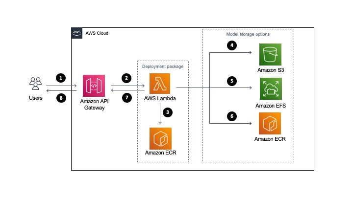
Jani Muuriaisniemi

Jani is a Principal Solutions Architect at Amazon Web Services based out of Helsinki, Finland. With more than 20 years of industry experience, he works as a trusted advisor with a broad range of customers across different industries and segments, helping the customers on their cloud journey.

Jose Juhala

Jose is a Solutions Architect at Amazon Web Services based out of Tampere, Finland. He works with customers in Nordic and Baltic, from different industries, and guides them in their technical implementations architectural questions.

Solving the Access Goldilocks Problem: RBAC for InsightAppSec Is Here

Post Syndicated from Tom Caiazza original https://blog.rapid7.com/2021/11/01/solving-the-access-goldilocks-problem-rbac-for-insightappsec-is-here/

Solving the Access Goldilocks Problem: RBAC for InsightAppSec Is Here

We’re all familiar with the story of Goldilocks and the Three Bears. Goldilocks starts a new job as a security specialist on the security team at Three Bears’ Porridge, Inc. and is given access to their application security platform.

At first, the access she’s given is far too broad. It causes problems, and she has access to more data than she needs to do her job. By the end of the day, it’s impacted the entire system. The next day, she’s given too little access, preventing her from fully completing her tasks and creating more work for Hansel, Gretel, and the rest of the security team. Finally, after several rounds of granting and restricting permissions, they eventually land on an access level that’s just right.

Does this famous yarn hit a little too close to home?

Getting access control just right

Providing the right access levels to different teams and individual team members is a critical component of managing any security program, but it can be time-consuming, cumbersome, and rife with constant back-and-forth.

That’s why we’re excited to announce a new feature standard for InsightAppSec called Role-Based Access Control (RBAC). Our RBAC system gives you the flexibility to provide the right levels of access to the InsightAppSec platform needed for each role on your security team. By identifying users through groups, you can grant access and permissions quickly and easily, reducing back-and-forth setting up access that may have caused your team more than one porridge hangover.

The InsightAppSec RBAC feature works under a simple premise: scalability. RBAC allows you to create groups with bespoke levels of access based on what they need to actually do their jobs. The role a user is given will govern what they can see in the product in terms of features — for example, can they see the scan configs or vulnerabilities areas? — but their data access will define if they can actually see any data within those areas.

It doesn’t matter if you have a department of 10 or 20 — everyone assigned to designated groups will have the right access parameters to successfully carry out their tasks. Those parameters are easily updated to roll with changes as needed, and they’re fully customizable. With a few clicks, RBAC lets you set the access levels your entire security team needs to operate.

Go for the Goldilocks zone

So, why is this so important? Well, on day one, Goldilocks had far too much access and nearly brought the operation to a screeching halt. Having too many team members with unneeded access invites risk, and cleaning up that mess can be time-consuming and difficult. Similarly, day 2 wasn’t much better. Goldilocks didn’t have the permissions she needed and couldn’t contribute to the team (through no fault of her own). That meant the slack needed to be picked up somewhere, putting stress on the entire team and slowing the operation down.

If Three Bears’ Porridge, Inc. had the new RBAC, Goldilocks and the other members of her team or in her group would have had the permissions they needed from day 1, saving time, headaches, and money.

But the conveniences go further than that. InsightAppSec’s RBAC feature allows you to better partner with the dev team, providing them direct access to their application vulnerability details and context. That means less back-and-forth, less time lost, and a system that will scale with your business.

The RBAC feature allows you to do more than create custom roles. You can control access to applications in bulk with just a few clicks — and with our prebuilt roles, you can use the feature right out of the proverbial box (and customize from there).

This is one of the many features we’ve been working on this year to make your life at work just a little bit safer, more streamlined, and efficient. Current InsightAppSec customers will see that they may already have access to RBAC, and it will be rolled out for other parts of the Insight platform in the coming months. If you’d like to learn more, check out this handy video:

Solving the Access Goldilocks Problem: RBAC for InsightAppSec Is Here

As for Goldilocks, she’s been promoted to security administrator and is dreaming of becoming a CISO. And they lived happily ever after.

NEVER MISS A BLOG

Get the latest stories, expertise, and news about security today.

Има нещо гнило в Банкя

Post Syndicated from original https://bivol.bg/%D0%B8%D0%BC%D0%B0-%D0%BD%D0%B5%D1%89%D0%BE-%D0%B3%D0%BD%D0%B8%D0%BB%D0%BE-%D0%B2-%D0%B1%D0%B0%D0%BD%D0%BA%D1%8F.html

понеделник 1 ноември 2021


Гледайки как се развива предизборната надпревара, оставам с впечатление, че повечето партии, които се обявяват открито срещу банкенския специалист по корелациите между класическите италианска и английска литератури, забравят нещо много…

FSF: Free Software Awards nominations sought

Post Syndicated from original https://lwn.net/Articles/874637/rss

The Free Software Foundation has opened
nominations
for the Free Software
Awards
. Nominations are open until November 30.

The dedication of the developers, documentation writers, community
organizers, and volunteers of the free software movement is what has helped
us all live
liberation
in the years the free software movement has been
active. Just using free software makes you part of our collective journey
to freedom, but some go above and beyond in their dedication to the free
software movement. Now, it’s time for us to show those community members
and projects that we appreciate their vital work.

[…] Maybe you’ve been inspired by the work of a particular member of the free software community, or have been impressed by the great strides made by a project that incorporates free software into their platform for social change.

The collective thoughts of the interwebz