Implementing network traffic inspection on AWS Outposts rack

Post Syndicated from Art Baudo original https://aws.amazon.com/blogs/compute/implementing-network-traffic-inspection-on-aws-outposts-rack-2/

This post is written by Arun Kumar N C, Technical Account Manager; Debapriyo Jogi, Technical Account Manager; and Ashish Nagaraj, Cloud Support Engineer 2

Organizations are increasingly adopting hybrid cloud architectures that combine the scalability of cloud computing with the control and compliance benefits of on-premises infrastructure. AWS Outposts extends AWS infrastructure, AWS services, APIs, and tools to on-premises locations for workloads that require low latency, local data processing, or data residency. Outposts comes in a variety of form factors, from 42U Outposts racks to 1U and 2U Outposts servers. This post will focus on implementing network traffic inspection on Outposts rack.

Comprehensive security is critical for organizations deploying production workloads on Outposts. Network traffic inspection serves as a crucial security control, protecting against threats while enabling secure communication between different network segments. This post provides guidance on how to implement effective network traffic inspection across your hybrid cloud infrastructure using Outposts rack.

Overview

In the coming sections we will cover strategies for network traffic inspection on Outposts rack, focusing on outbound internet access and communication with on-premises networks. We explore AWS native services and third-party tools, offering a comprehensive overview of your options. We will cover architectural patterns, implementation guides, and best practices to help build a strong security posture for your hybrid cloud environment.

Securing internet-facing applications

Securing internet-facing applications on Outposts requires a robust, multi-layered approach for high availability and comprehensive security. We will explore two key architectural patterns that ensure enterprise-grade security for your workloads below.

Amazon CloudFront with AWS WAF integration

This architecture uses multiple AWS services including AWS Shield and AWS WAF for multi-layered security, Amazon CloudFront for global content delivery, and an Application Load Balancer (ALB) on Outposts for on-premises traffic management. Applications are deployed on Outposts, with CloudFront as the content delivery network. AWS WAF rules on CloudFront protect against web exploits, while the ALB distributes requests to application instances within Outposts.

This diagram illustrates AWS CloudFront with WAF integration connecting AWS cloud services to a customer data center through the internet. The setup includes CloudFront protected by WAF and Shield, EC2 instances in a VPC, and an Outpost deployment in the customer data center with ALB and EC2 instances.

Figure 1 – Amazon CloudFront with AWS WAF integration

  1. User sends a request via web browser or mobile app to access the application.
  2. The request is received by the CloudFront in AWS Edge Location, performing content-based routing.
  3. CloudFront integrates with AWS WAF to filter web traffic and block common attack patterns.
  4. ALB routes it to the appropriate targets.
  5. The application on Outposts processes the request and generates a response.

This flow ensures secure and efficient handling of user requests using both cloud and on-premises resources.

ALB with AWS WAF


This architecture offers more control over traffic routing while using AWS WAF for security. Applications are deployed on Outposts, but the ALB is in the parent Region, as AWS WAF cannot be associated with Outposts ALBs. The regional ALB handles incoming traffic, with AWS WAF providing firewall capabilities. After passing through AWS WAF, traffic is routed to Outposts applications. This configuration allows advanced WAF features but may introduce latency, as traffic must first reach the regional ALB. This trade-off between security and latency should be considered based on application needs.

Note: A critical dependency exists on the service link connection, as application traffic routing relies on the regional ALB. Service link failures will disrupt workload operations, making connection resilience essential for this architecture.

Figure 2 – ALB with AWS WAF

  1. User sends a request via web browser or mobile app for a webpage, API call, or service.
  2. The ALB in the AWS Region receives the request and performs Layer 7 content-based routing.
  3. ALB integrates with AWS WAF for security inspection.
  4. If the request passes, ALB routes it to the appropriate target in Outposts, selecting a specific instance or service.
  5. The application on Outposts processes the request, generates a response, and returns it.
  6. The response travels back through Outposts ALB to the regional ALB, which forwards it to the user’s browser or app.

Inspection between the Outpost subnet and regional subnet

Network traffic inspection between the Outpost and regional subnets is vital for security in hybrid cloud deployments. It makes sure traffic between Outposts and the parent Region complies with security policies and requirements. Two main architectural approaches exist for implementing this inspection:

  1. Using a third-party firewall in the Outpost subnet.
  2. Using AWS Network Firewall in an AWS Region.

Both approaches support various connectivity (service link) options between Outposts and the Region, including AWS Direct Connect.

Using third-party firewall in the Outpost subnet

This architecture uses a third-party firewall in the Outposts subnet, routing all traffic between the Outposts and regio0nal subnets through it. This setup enables local traffic inspection, reducing latency while enforcing security policies before traffic leaves the Outposts.

This diagram illustrates AWS Region and customer data center connected via service-linked VPN. Outpost deployment includes third-party firewall EC2 instance and target EC2 instances in Outpost subnet.

Figure 3 – Third-party firewall in the Outpost subnet

Traffic can originate from either Outposts or AWS regional subnet.

  1. Traffic originating from the Outpost to AWS Region:

a. Traffic is sent to the third-party firewall in the Outpost.
b. The firewall inspects the traffic and applies security policies.
c. If allowed, the firewall forwards traffic to the Region.
d. Traffic travels via service link connectivity (Direct Connect or public internet) to the regional subnet.

  1. Traffic originating from AWS Region to the Outpost:

a. Traffic originates in the regional subnet.
b. Traffic travels via service link connectivity (Direct Connect or public internet).
c. Upon reaching the Outpost, the traffic is sent to the third-party firewall.
d. The firewall inspects packets and applies security policies.
e. If allowed, the firewall forwards traffic to the Outpost subnet destination.

Using AWS Network Firewall in an AWS Region

In this architecture, a Network Firewall is deployed in the regional VPC, routing all traffic between the Outpost and regional subnets through it. This centralized approach ensures consistent policy enforcement with AWS native tools. The firewall inspects all traffic between Outposts and the AWS infrastructure in the Region.

This diagram illustrates AWS Network Firewall in a Region connected to customer data center via service-linked VPN. Includes VPC with Network Firewall, and EC2 in Outpost routing the traffic through the AWS Network Firewall endpoint.

Figure 4 – AWS Network Firewall in an AWS Region

Traffic can originate from either the Outposts subnet or AWS regional subnet.

All traffic is routed to the Network Firewall in the AWS Region.

  1. The firewall applies configured rules, including:
  • Custom rules for specific security needs.
  • Managed AWS rule groups for common threats.
  • Third-party rule groups for specialized protection.
  1. If traffic passes all rules, it is forwarded to its destination (Outpost or Region).
  2. Return traffic follows the same path, all traffic is inspected by the Network Firewall.

Inspection between on-premises and Outposts through Local Gateway

Network traffic inspection between on-premises networks and Outposts via Local Gateway (LGW) is essential for securing hybrid environments. It helps you make sure safe communication is happening between Outposts workloads and on-premises infrastructure.
Two primary architectural approaches are available explained below. The choice depends on infrastructure, security needs, and operational preferences.

Using third-party firewall on Outposts

For more details on implementing network traffic inspection between on-premises networks and Outposts via LGW, refer to Implementing network traffic inspection on AWS Outposts rack.

This post expands on the preceding blog by offering detailed guidance on architectural options and traffic flows for inspecting network traffic between on-premises environments and Outposts via LGW.

Using your on-premises router/firewall

This approach uses the existing firewall capabilities of your on-premises router/firewall. The network is configured to route all traffic between the on-premises environment and Outposts through this router/firewall. The LGW on your Outpost connects directly to your router/firewall, which handles the firewall functions. This setup uses the on-premises security infrastructure and policies, ensuring continuity in security management while integrating Outposts into the broader network security strategy.

Traffic flow:

  1. Traffic originates from on-premises network
  2. Passes through your router with the firewall
  3. Router inspects the traffic
  4. If allowed, traffic is sent to Outposts through the LGW
  5. Outbound inspection to the internet from Outposts instances

Outbound inspection to the internet from Outposts instances

Outbound internet traffic inspection for Outposts instances is useful for security and controlling access to external resources. Three architectural approaches are available for implementing this inspection, which are discussed in the following sections.

Using Customer-Owned IP (CoIP) with on-premises firewall

In this architecture, Outposts instances are assigned Customer-Owned IP (CoIP) addresses, with all outbound internet traffic routed through the on-premises network and firewall. The LGW connects the Outposts environment to the on-premises network. This setup enables organizations to leverage existing on-premises security and internet connectivity while ensuring consistent IP addressing across their hybrid environment.

This diagram illustrates Customer-Owned IP (CoIP) implementation in a customer data center, where Outpost EC2 instances use CoIP addresses, routing through LGW to an on-premises firewall for inspection.

Figure 5 – Customer-Owned IP (CoIP) with on-premises firewall

  1. An Outposts instance with a CoIP address initiates outbound internet traffic.
  2. The traffic is routed to the LGW on the Outpost.
  3. The LGW forwards the traffic to the on-premises network.
  4. The traffic reaches the on-premises firewall and inspects the traffic, applying security policies and rules.
  5. If allowed, the firewall forwards the traffic to the internet through the on-premises connection.
  6. Return traffic follows the reverse path, being inspected by the firewall before reaching the Outposts instance.

Using CoIP with third-party firewalls on Outposts

Using this configuration, you would assign a CoIP addresses to your Outposts instances and deploy a third-party firewall appliance directly on the Outposts rack. Outbound internet traffic from these instances is routed through the local firewall running on EC2 before reaching the internet via the LGW. This approach ensures local traffic inspection while preserving the advantages of CoIP addressing, enabling seamless integration with existing IP management systems.

This diagram illustrates third-party firewalls on Outposts as EC2 instances. Customer data center contains Outpost subnet with EC2 instances using CoIP, connected to LGW. Traffic routes through Customer Edge Router/Firewall before reaching Internet

Figure 6 – CoIP with third-party firewalls on Outposts

  • An Outposts instance with a CoIP address initiates outbound internet traffic.
  • The traffic is routed to the third-party firewall deployed on the Outpost.
  • The firewall performs deep packet inspection, applying security policies and rules.
  • If allowed, the firewall forwards the traffic to the LGW.
  • The LGW sends the traffic to the internet through the on-premises connection.
  • Return traffic follows the reverse path, being inspected by the firewall before reaching the Outposts instance.

Using Internet Gateway (IGW) with Network Firewall in the Region

This architecture provides secure outbound internet access for Outposts workloads by using services in the parent Region. The VPC extends to include the Outposts rack, with internet-bound traffic routed via the service link to the AWS Region. In the Region, the Network Firewall inspects the traffic before forwarding it to the Internet Gateway (IGW) for internet access.

Traffic flow:

  1. Traffic is sent to the parent Region via the service link.
  2. In the Region, traffic is routed to the Network Firewall.
  3. The Network Firewall inspects the traffic and applies rules.
  4. If allowed, traffic is forwarded to the IGW via the NAT Gateway.
  5. The IGW sends the traffic to the internet.
  6. Return traffic follows the reverse path, inspected before reaching Outposts.

Conclusion

Implementing effective network traffic inspection for AWS Outposts requires a strategic approach balancing security, efficiency, and architectural complexity. We’ve explored multiple architectural patterns for implementing network traffic inspection with Outposts rack.

Reach out to your AWS account team or AWS support to learn more about inspection in Outpost.

[$] OSI election ends with unsatisfying results

Post Syndicated from jzb original https://lwn.net/Articles/1014603/

The Open Source Initiative
(OSI) has announced
the results of its recent board of directors election. Ruth Suehle and
McCoy Smith are new to the board, while Carlo Piana will serve another
term. The results, however, seem tainted in the eyes of some
participants and observers. The election has been plagued by missteps
from the beginning. It has culminated with the exclusion of three
candidates for failing to meet a requirement to sign the OSI board agreement, which was added after the election was over and before results were tallied or announced.

Friday Squid Blogging: A New Explanation of Squid Camouflage

Post Syndicated from Bruce Schneier original https://www.schneier.com/blog/archives/2025/03/friday-squid-blogging-a-new-explanation-of-squid-camouflage.html

New research:

An associate professor of chemistry and chemical biology at Northeastern University, Deravi’s recently published paper in the Journal of Materials Chemistry C sheds new light on how squid use organs that essentially function as organic solar cells to help power their camouflage abilities.

As usual, you can also use this squid post to talk about the security stories in the news that I haven’t covered.

Improving email security with Amazon SES Mail Manager and Hornetsecurity’s Vade Advanced Email Security Add On

Post Syndicated from Zip Zieper original https://aws.amazon.com/blogs/messaging-and-targeting/improving-email-security-with-amazon-ses-mail-manager-and-hornetsecuritys-vade-advanced-email-security-add-on/

Email continues to be a critical communication channel for businesses, powering essential communications across time zones and locations. But as cyber threats grow more sophisticated, how can organizations protect their most vulnerable communication channel? With the increasing complexity of email-based security risks, businesses need robust solutions to safeguard their digital communications. Today, we’re excited to announce the launch of Hornetsecurity’s Vade Advanced Email Security Add On for Amazon Simple Email Service (SES) Mail Manager, a powerful new tool in the fight against email-borne threats.

Amazon SES: Powering email communication at scale

Amazon SES is a cloud-based email service that helps you automate high-volume email communications seamlessly. In May 2024, we launched Mail Manager, introducing email relay and gateway features that help you manage email traffic, ensure compliance and enforce corporate policies. The launch also included an introduction to Mail Manager Email Add Ons which provides optional access to a collection of powerful security tools from certified providers that help you manage and filter incoming emails. Add Ons from our partners deliver advanced email security with flexible, meter-based pricing that is easily activated and integrated into your email workflows directly from the Mail Manager console or Mail Manager APIs.

In this blog, we’ll introduce Hornetsecurity’s Vade Email Add On for Amazon SES Mail Manager, and demonstrate how to enable its advanced email security capabilities to help protect your critical email communications.

Introducing the Vade Email Add On by Hornet Security

Hornetsecurity, a global leader in email security, produces next-generation cloud-based security, compliance, backup, and security awareness solutions that help companies and organizations of all sizes around the world. Its email filters process billions of emails daily, using a vast global email database to power their artificial intelligence (AI) engine. This approach allows the Vade Email Add On to continuously refine and adapt to the latest email threats and filter-bypassing techniques.

The Vade Email Add On brings Vade’s expertise directly to you, providing a seamless and powerful email security solution within the familiar AWS environment:

“Enhance your email service with advanced cybersecurity capabilities by integrating Vade Email Security’s state-of-the-art filtering solution. This Add On empowers users with automated, real-time defense against spam, malware, and phishing—ensuring safer communication. Vade’s AI-powered technology employs a multi-layered approach—combining heuristics, behavioral analysis, and natural language processing—to analyze messages in real time. Strengthen your platform by ensuring ongoing protection against evolving cyber threats.”

Advanced Email Security with the Vade Add On for Mail Manager

Hornetsecurity’s Vade Add On for Mail Manager provides automated, real-time defense against spam, malware, and phishing, which help ensure safer communication, including:

  • Advanced Threat Detection: Identifies and blocks sophisticated phishing attempts, malware, and ransomware, providing comprehensive protection against a wide range of cyber threats.
  • Behavioral Analysis: Examines the behavior patterns of message senders and content based on over 130 potential data points in each message to detect anomalies and potential threats.
  • Patented AI Technology: Leverages proprietary AI algorithms to analyze communication patterns and detect misuse of your service’s digital assets. This technology is powered by our global network of over 1 billion protected mailboxes.
  • Real-Time Scanning: Instantly analyze attachments without delaying delivery, thanks to its real time code interpreter.
  • Ease of Use: Seamless integration with Mail Manager rules, scanning only messages that meet specific criteria.

The Vade Email Add-On integrates with Mail Manager’s rules engine. This engine routes messages based on Vade’s scan results and optional detailed verdicts. These verdicts enable precise categorization and handling of incoming emails, improving security and email management.

Configure the Vade Email Add On

In the following example, we’ll walk thru the steps needed to subscribe and configure a rule set with two rules that are processed in priority order:

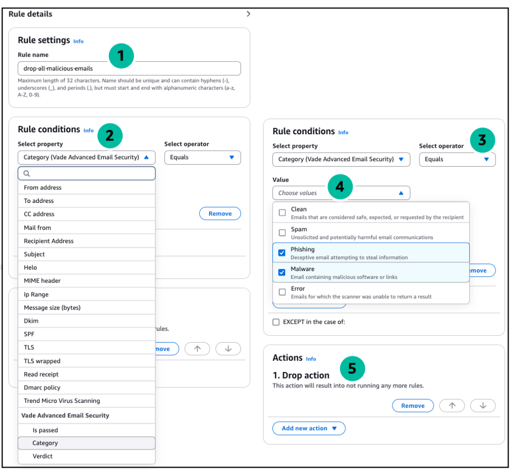
  • Rule 1 – drop-all-malicious-emails This rule has a condition that uses Vade to scan all incoming email and identify messages that are malicious (contain malware or phishing). These messages are then processed by Rule 1’s “Drop action“. Messages that are deemed “safe” are passed to Rule 2 after automatically being inspected and marked as “likely to be spam”, or “not-spam”.
  • Rule 2 – forward-to-mailbox Messages passed into Rule 2 are immediately forwarded to the user’s mailbox. In our example, we’re using Amazon WorkMail and Mail Manager’s built-in “Deliver to mailbox” action.
    • The Vade Add On also distinguishes between spam and clean email, and automatically adds a corresponding header to each message (see below) that can be used to route spam into the user’s “junk” folder.
      • X-SES-Vade-Advanced-Email-Security-AddonVerdict: spam:high
    • Thanks to the seamless integration between Mail Manager Add Ons and WorkMail, messages marked as spam are automatically sent to the user’s Junk folder, enhancing both security and user experience.

Vade Email Add On workflow

Follow the steps below to configure the Vade Email Add On using the Amazon SES console for the simple mail flow described above (note – the SES Mail Manager API can be used in lieu of the console).

  1. Open the Amazon SES console and in the left navigation rail, expand Mail Manager and click Email Add Ons.
  2. Select the Vade Add On, read the description. Click Subscribe and read the Terms and Conditions. Click Subscribe again to activate the Vade Advanced Email Security Add On in your SES account.
    • Pricing is detailed in the Email Add On description page. When this blog was published the price per 1,000 emails processed = $0.415 USD (subject to change, please refer to SES Pricing for the most up to date information).

Vade Email Add On

  1. In the left navigation rail under Mail Manager, click Rule Sets.
  2. Create a new Rule set ( process-via-vade ) (or modify an existing Rule set).
    1. Create a rule ( drop-all-malicious-emails )
    2. Under Rule conditions, click select property and select Vade Advanced Email Security Category from the drop-down menu (note the property modifiers allow for increasingly detailed inspection / results for the scan).
    3. Click the Select operator drop-down and select Equals from the menu.
    4. Click the Value drop-down and select Phishing and Malware.
    5. Under Actions, select Drop action to stop processing and discard messages that are found to be malicious.

Rule 1 - drop-all-malicious-emails

  1. Create rule ( forward-to-mailbox ) to process messages that were passed along by Rule 1.
  2. Under Actions, select Deliver to mailbox (note – if not using Amazon WorkMail, you would select a previously configured SMTPRelay action to send messages to your inbox provider. See this blog for more info).
    1. Provide your WorkMail ARN
    2. Select an IAM role that has permission for SES Mail Manager to access to your WorkMail mailbox

Rule 2 - forward-to-mailbox

  1. Save the Rule set (it will look like this):

New Vade Rule Set

  1. To use this new Rule set, add it to an active Mail Manager Ingress endpoint. When you click save, the Ingress endpoint will begin using the new Rule set immediately.

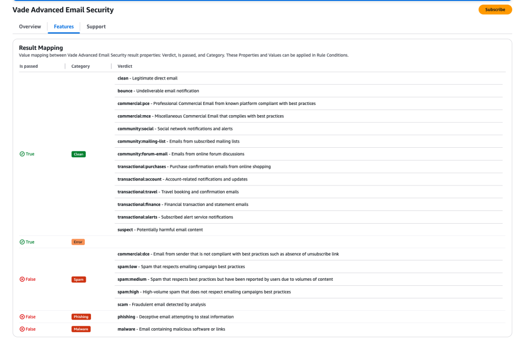
The Vade Add-On’s rule conditions (below) enable granular control of email routing. When combined with customizable actions, these rules create an automated email handling system that matches your business needs.

VADE result mapping

Conclusion

Hornetsecurity’s Vade Email Add On for Amazon SES Mail Manager represents a significant step forward in email security for Amazon SES Mail Manager customers. By combining an advanced artificial intelligence (AI)-driven security engine with the powerful management capabilities of Mail Manager, you can enhance your defense against email-borne threats while maintaining precise control over your email workflows.

Get started today and take your email security to the next level with the Vade Add On for Amazon SES Mail Manager

We encourage you to try the Vade Add On for Amazon SES Mail Manager and experience the benefits of enhanced email security firsthand. To learn more about implementation details and best practices, please visit:

Join the Conversation:
Connect with other administrators and security professionals on the AWS re:Post community to share insights and learn best practices.

Optimizing network footprint in serverless applications

Post Syndicated from Chris McPeek original https://aws.amazon.com/blogs/compute/optimizing-network-footprint-in-serverless-applications/

This post is authored by Anton Aleksandrov, Principal Solution Architect, AWS Serverless and Daniel Abib, Senior Specialist Solutions Architect, AWS

Serverless application developers may commonly encounter scenarios where they need to transport large payloads, especially when building modern cloud applications that need rich data. Examples include analytics services with detailed reports, e-commerce platforms with extensive product catalogs, healthcare applications transmitting patient records, or financial services aggregating transactional data.

Many serverless services have a well-defined maximum payload size. For example, AWS Lambda maximum request/response payload size is 6 MB, and Amazon Simple Queue Service (Amazon SQS) and Amazon EventBridge maximum message size is 256 KB. In this post, you will learn how to use data compression techniques to reduce your network footprint and transport larger payloads under existing constraints.

Overview

Cloud applications evolve continuously and need to be adjusted frequently for new requirements, such as new business features or new Service Level Objectives (SLO) for higher throughput and lower latency. As new use cases and data patterns are added, it is common to see request and response payload sizes increase. At some point, you might hit the maximum service payload size limits, such as 6 MB for synchronous Lambda function invokes, 10 MB for Amazon API Gateway, and 256 KB for Amazon SQS, EventBridge, and asynchronous Lambda invokes.

There are several techniques you can apply when dealing with large payloads. If your payloads are tens of MBs or more, or you need to transport large binary objects with API Gateway, you can store the payload on Amazon Simple Storage Service (Amazon S3) and use pre-signed URLs for clients to directly upload and download from S3.

A sample of architecture for handling large payloads.

Figure 1. A sample of architecture for handling large payloads

Lambda function URLs response streaming supports up to 20 MB responses. For handling large messages with services such as SQS or EventBridge, you can store the message in S3 and pass a reference. The downstream consumer will use the reference to download the message directly from S3. One common characteristic of these techniques is that they introduce architectural complexity and may necessitate modifications to your existing solution architecture and data flow patterns.

Furthermore, as your payloads grow in size, you will see increased data transfer costs, especially if your solution is transporting data through Amazon Virtual Private Cloud (VPC) NAT Gateways, VPC endpoints, or sending data across AWS Regions. For example, it is common for VPC-based solutions to have Lambda functions in their architecture. A container running on Amazon Elastic Kubernetes Service (Amazon EKS) might need to invoke a Lambda function, or a VPC-attached Lambda function might need to reach out to the public internet.

Examples of using virtual network appliances with serverless applications.

Figure 2. Examples of using virtual network appliances with serverless applications

Both NAT Gateway and VPC Endpoint are billed per GB of data processed, which makes data compression a valuable optimization technique. Go to NAT Gateway pricing and VPC Endpoint pricing for details.

The following sections explore data compression techniques and demonstrate how to apply them in your serverless applications. You can learn how to send larger payloads within the existing payload size boundaries and reduce your network footprint without significant architectural changes. This post discusses compression techniques in the context of Lambda and API Gateway, but the same principles can be applied to other services, such as SQS, EventBridge, and AWS AppSync. Understanding compression concepts better equips you to optimize your application’s data-handling capabilities.

What is data compression?

Compression is a widely used approach to reduce data size in order to improve cost-effectiveness and performance for data storage and transmission. Many tools and frameworks incorporate data compression techniques, such as gzip or zstd. It is thoroughly documented in the official IANA specification and IETF RFC 9110. Browsers such as Chrome and Firefox, HTTP toolkits such as curl and Postman, and runtimes such as Node.js and Python natively handle compression, often without user involvement.

Consider HTTP protocol. When a client wants to send a compressed payload, it specifies it in the Content-Type header. To receive a compressed response, the client specifies supported compression methods in the Accept-Encoding request header.

Accept-Encoding request header specifying supported compression methods.

Figure 3. Accept-Encoding request header specifying supported compression methods

The server compresses the response payload using one of the supported methods and uses the Content-Encoding response header to indicate the method to the client.

Content-Encoding response header specifying compression method.

Figure 4. Content-Encoding response header specifying compression method

This mechanism can accelerate client-server communications by reducing the number of bytes transmitted over the network. Compression efficiency depends on the data type. Text-based formats like JSON, XML, HTML, and YAML compress well, while binary data such as PDF and JPEG generally compress less effectively.

Data compression with API Gateway

API Gateway provides built-in compression support. Use the minimumCompressionSize configuration to set the smallest payload size to compress automatically. The value can be between 0 bytes to 10 MB. Compressing very small payloads might actually increase the final payload size, and you should always test with your real payload patterns to determine the optimal threshold.

Handling data compression in API Gateway.

Figure 5. Handling data compression in API Gateway

API Gateway enables clients to interact with your API using compressed payloads through supported content encodings. The compression mechanism works bi-directionally. For JSON payloads, API Gateway seamlessly handles compression and decompression, maintaining compatibility with mapping templates. It decompresses incoming payloads before applying request mapping templates and compresses outgoing responses after applying response mapping templates. This automated compression optimizes data transfer:

  • When sending compressed data, clients supply the appropriate Content-Encoding header. API Gateway handles the decompression and applies configured mapping templates before forwarding the request to the integration.
  • When API Gateway receives an integration response and compression is enabled, it compresses the response payload and returns it to the client, provided that the client has included a matching Accept-Encoding header.

A sample test using the compression technique with API Gateway and JSON payload yielded the following results.

  • Compression disabled. Response size = 1 MB, response latency = 660 ms
  • Compression enabled. Response size = 220 KB, response latency = 550 ms

Compressing data resulted in 78% network footprint reduction and improved latency by 110 ms.

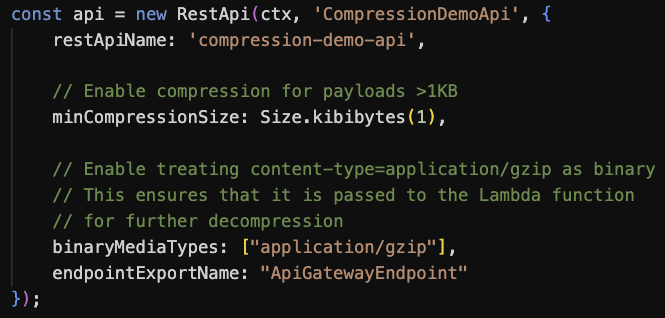
This configuration-based technique uses the API Gateway native compression. However, payloads are decompressed before being delivered to downstream integrations, thus they still remain subject to Lambda’s 6 MB max payload size. To address this, you can configure binaryMediaTypes in the API Gateway to pass compressed payloads to Lambda directly, enabling the function to handle decompression.

CDK code to configure API Gateway for data compression and binary data passthrough.

Figure 6. CDK code to configure API Gateway for data compression and binary data passthrough

Handling compressed data in Lambda functions

The Lambda Invoke API supports payloads in plain-text formats, such as JSON. The maximum payload size is 6 MB for synchronous invocations and 256 KB for asynchronous. Although the Invoke API supports uncompressed text-based payloads, you can introduce data compression in your function code and use API Gateway or Function URLs to facilitate content conversion, as illustrated in the following figure.

Transporting compressed payloads in a serverless applications.

Figure 7. Transporting compressed payloads in a serverless applications

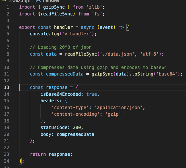
Handling data compression in your Lambda function code can be done through libraries commonly embedded in the runtime. The following code snippet shows the compressing response payload using Node.js. Similar techniques can be applied to other runtimes.

Sample code implementing response payload compression in a Lambda function.

Figure 8. Sample code implementing response payload compression in a Lambda function

  • Line 1: Import gzip functionality from the zlib module.
  • Lines 11: Compress and Base64-encode data. Gzip compression, similar to many other compression methods, produces a binary stream. Base64 encoding converts it to the text-based format expected by the Lambda service
  • Lines 13-21: Response object is created with isBase64Encoded=true and response headers telling the client that the response is a gzip-encoded JSON object.

The following screenshot shows the result: 20 MB uncompressed JSON returned from a Lambda function as a 2.5 MB compressed response body. Network footprint reduced by over 80%.

A screenshot from Postman showing the original and compressed payload size.

Figure 9. A screenshot from Postman showing the original and compressed payload size

Using this technique, you can reduce your network footprint and transport payload sizes several times higher than the Lambda maximum payload size.

Using Function URLs with compressed payloads

Transporting compressed payloads through Lambda Function URLs doesn’t necessitate any extra configuration. For handler responses, your code needs to compress and Base64-encode the data as shown in the preceding figure. For invocation requests, the Function URL endpoint recognizes the incoming compressed payload as binary and passes it to your handler as a Base64 encoded string in the event body.

Sample code implementing request payload decompression in a Lambda function.

Figure 10. Sample code implementing request payload decompression in a Lambda function

Trade-offs and testing results

Compressing data in function code is a CPU-intensive activity, potentially increasing invocation duration and, as a result, function cost. This, however, can be balanced by the benefits of data compression. As you’ve seen in previous sections, while compressing data adds compute latency, transporting smaller payloads over the network reduces network latency. The following section summarizes a series of tests performed to estimate the impact of data compression on Lambda function invocation duration, Lambda function invocation cost, and data transfer savings with both NAT Gateway and VPC Endpoint. The tests were performed with several assumptions and randomly generated JSON data. You can see full testing results in the sample GitHub.com repo.

Test results demonstrated that the impact on function latency and cost primarily depends on two key factors: payload size and allocated memory (which determines vCPU capacity). Using a Node.js runtime with ARM architecture as an example, compressing a 1 MB JSON object in a function with 1 GB of allocated memory resulted in 124 ms of added processing time on average. For 10 million invocations, this extra processing time adds approximately $16. At the same time, the compression yielded a 70% reduction in payload size. With the same number of invocations, this translates to approximately $300 in savings when using NAT Gateway and $70 in savings when using VPC Endpoints (depending on the number of Availability Zones (AZs)).

AWS Service pricing is updated regularly, you should always consult the respective pricing pages for the latest information. Moreover, you should conduct your own performance and cost estimates using payloads that represent your workloads. Compression effectiveness varies significantly depending on the data type: payloads with low compression rates might not benefit from this technique.

Sample application

Follow the instructions in this GitHub repository to provision the sample in your AWS account. The project creates two Lambda functions to demonstrate receiving and returning compressed JSON using Function URLs and API Gateway.

The sample shows how to GET and POST JSON payloads using gzip compression to reduce the network footprint by over 80%.

A screenshot from Postman showing the original and compressed payload size.

Figure 11. A screenshot from Postman showing the original and compressed payload size

Conclusion

Data compression enables larger payload transfers and reduces network footprint. It can help to lower network latencies and optimize data transfer costs. When implementing compression within Lambda functions, it is important to consider its CPU-bound nature, which may increase function duration and costs. You should always evaluate the added compute cost against potential data transfer savings to make sure the technique benefits your use case.

Compression is most effective for handling large text-based payloads and when a slight increase in compute latency balanced by reduced network latency is acceptable.

To learn more about Serverless architectures and asynchronous Lambda invocation patterns, see Serverless Land.

Metasploit Wrap-Up 03/21/2025

Post Syndicated from Simon Janusz original https://blog.rapid7.com/2025/03/21/metasploit-wrap-up-03-21-2025/

SMB to LDAP Relay

Metasploit Wrap-Up 03/21/2025

This week, the Metasploit team have added an exciting relay module that has been in the works for a long time. This relay module is used to host an SMB server, and execute an SMB to LDAP relay attack against a Domain controller with an LDAP server when NTLMv1 is being used as the SMB authentication method. PetitPotam can be used to coerce authentication on the victim system and relay it to the Domain Controller.
The module automatically takes care of removing the relevant flags to bypass signing.
This module supports the usage of SMBv2 and SMBv3, and captures NTLMv1 and NTLMv2 hashes which can be used for a pass-the-hash attack, or cracked locally to retrieve raw passwords.
When successful, this attack can also open a Metasploit Framework LDAP session. This session can then be leveraged to set up a Resource-Based Constrained Delegation (RBCD) on the Domain Controller to get remote code execution on the victim system.

New module content (1)

Microsoft Windows SMB to LDAP Relay

Authors: Christophe De La Fuente and Spencer McIntyre
Type: Auxiliary
Pull request: #19832 contributed by cdelafuente-r7
Path: server/relay/smb_to_ldap

Description: Adds a module that runs an SMB capture server that relays the credentials to one or more LDAP servers, verifies the credentials, and can establish an LDAP session with the relayed authentication.

Bugs fixed (1)

  • #19960 from jheysel-r7 – This fix adds more reliable check method and takes into account the revision number when running the Windows Kernel Time of Check Time of Use LPE (CVE-2024-30038) module.

Documentation

You can find the latest Metasploit documentation on our docsite at docs.metasploit.com.

Get it

As always, you can update to the latest Metasploit Framework with msfupdate
and you can get more details on the changes since the last blog post from
GitHub:

If you are a git user, you can clone the Metasploit Framework repo (master branch) for the latest.
To install fresh without using git, you can use the open-source-only Nightly Installers or the
commercial edition Metasploit Pro

My Writings Are in the LibGen AI Training Corpus

Post Syndicated from Bruce Schneier original https://www.schneier.com/blog/archives/2025/03/my-writings-are-in-the-libgen-ai-training-corpus.html

The Atlantic has a search tool that allows you to search for specific works in the “LibGen” database of copyrighted works that Meta used to train its AI models. (The rest of the article is behind a paywall, but not the search tool.)

It’s impossible to know exactly which parts of LibGen Meta used to train its AI, and which parts it might have decided to exclude; this snapshot was taken in January 2025, after Meta is known to have accessed the database, so some titles here would not have been available to download.

Still…interesting.

Searching my name yields 199 results: all of my books in different versions, plus a bunch of shorter items.

[$] The guaranteed contiguous memory allocator

Post Syndicated from corbet original https://lwn.net/Articles/1015000/

As a system runs and its memory becomes fragmented, allocating large,
physically contiguous regions of memory becomes increasingly difficult.
Much effort over the years has gone into avoiding the need to make such
allocations whenever possible, but there are times when they simply cannot
be avoided. The kernel’s contiguous memory
allocator
(CMA) subsystem attempts to make such allocations possible,
but it has never been a perfect solution. Suren Baghdasaryan is is trying
to improve that situation with the guaranteed
contiguous memory allocator patch set
, which includes work from Minchan
Kim as well.

Julien Malka proposes method for detecting XZ-like backdoors

Post Syndicated from daroc original https://lwn.net/Articles/1015095/

Julien Malka has

called
for the NixOS project to use build-reproducibility to detect when a program has a maintainer-generated tarball that results in a different artifact than building from source. There are good reasons for projects to release maintainer-generated tarballs, but since the materials included in them are usually documentation, extra build scripts, and so on, it makes sense to check that they don’t influence the final build output. While this would not have stopped

last year’s XZ backdoor
, it would have made it harder to hide.

People are often convinced that OSS is more trustworthy than closed-source software because the code can be audited by practitioners and security professionals in order to detect vulnerabilities or backdoors. In this instance, this procedure has been made difficult by the fact that part of the code activating the backdoor was not included in the sources available within the git repository but was instead present in the maintainer-provided tarball. While this was used to hide the backdoor out of sight of most investigating eyes, this is also an opportunity for us to improve our software supply chain security processes.

[$] Multiple memory classes for address-space isolation

Post Syndicated from daroc original https://lwn.net/Articles/1014440/

Brendan Jackman has been working to try to get ahead of the next hardware CPU
vulnerability
before it gets discovered. In January, he posted the second version of

a patch set
that introduces

address-space isolation
(ASI) as a way of
preventing future CPU vulnerabilities from leaking important
information. The core concept is to ensure that data that is not currently
needed is not present in memory, so that speculative execution cannot leak it.
The work is nowhere near ready to be incorporated into the mainline
kernel — not least of all because it has a large performance impact in its
current form — but it is likely to once again be a topic of discussion at the
2025

Linux Filesystem, Memory Management, and BPF Summit
.

Connect, share, and query where your data sits using Amazon SageMaker Unified Studio

Post Syndicated from Lakshmi Nair original https://aws.amazon.com/blogs/big-data/connect-share-and-query-where-your-data-sits-using-amazon-sagemaker-unified-studio/

The ability for organizations to quickly analyze data across multiple sources is crucial for maintaining a competitive advantage. Imagine a scenario where the retail analytics team is trying to answer a simple question: Among customers who purchased summer jackets last season, which customers are likely to be interested in the new spring collection?

While the question is straightforward, getting the answer requires piecing together data across multiple data sources such as customer profiles stored in Amazon Simple Storage Service (Amazon S3) from customer relationship management (CRM) systems, historical purchase transactions in an Amazon Redshift data warehouse, and current product catalog information in Amazon DynamoDB. Traditionally, answering this question would involve multiple data exports, complex extract, transform, and load (ETL) processes, and careful data synchronization across systems.

In this blog post, we will demonstrate how business units can use Amazon SageMaker Unified Studio to discover, subscribe to, and analyze these distributed data assets. Through this unified query capability, you can create comprehensive insights into customer transaction patterns and purchase behavior for active products without the traditional barriers of data silos or the need to copy data between systems.

SageMaker Unified Studio provides a unified experience for using data, analytics, and AI capabilities. You can use familiar AWS services for model development, generative AI, data processing, and analytics—all within a single, governed environment. To strike a fine balance of democratizing data and AI access while maintaining strict compliance and regulatory standards, Amazon SageMaker Data and AI Governance is built into SageMaker Unified Studio. With Amazon SageMaker Catalog, teams can collaborate through projects, discover, and access approved data and models using semantic search with generative AI-created metadata, or you can use natural language to ask Amazon Q to find your data. Within SageMaker Unified Studio, organizations can implement a single, centralized permission model with fine-grained access controls, facilitating seamless data and AI asset sharing through streamlined publishing and subscription workflows. Teams can also query the data directly from sources such as Amazon S3 and Amazon Redshift, through Amazon SageMaker Lakehouse.

SageMaker Lakehouse streamlines connecting to, cataloging, and managing permissions on data from multiple sources. Built on AWS Glue Data Catalog and AWS Lake Formation, it organizes data through catalogs that can be accessed through an open, Apache Iceberg REST API to help ensure secure access to data with consistent, fine-grained access controls. SageMaker Lakehouse organizes data access through two types of catalogs: federated catalogs and managed catalogs (shown in the following figure). A catalog is a logical container that organizes objects from a data store, such as schemas, tables, views, or materialized views such as from Amazon Redshift. You can also create nested catalogs to mirror the hierarchical structure of your data sources within SageMaker Lakehouse.

  • Federated catalogs: Through SageMaker Unified Studio, you can create connections to external data sources such as Amazon DynamoDB. See Data connections in Amazon SageMaker Lakehouse for all the supported external data sources. These connections are stored in the AWS Glue Data Catalog (Data Catalog) and registered with Lake Formation, allowing you to create a federated catalog for each available data source.
  • Managed catalogs: A managed catalog refers to the data that resides on Amazon S3 or Redshift Managed Storage (RMS).

The existing Data Catalog becomes the Default catalog (identified by the AWS account number) and is readily available in SageMaker Lakehouse.

If the business units don’t have a data warehouse but need the benefits of one—such as a query result cache and query rewrite optimizations—then, they can create an RMS managed catalog in SageMaker Unified Studio. This is a SageMaker Lakehouse managed catalog backed by RMS storage. The table metadata is managed by Data Catalog. When you create an RMS managed catalog, it deploys an Amazon Redshift managed serverless workgroup. Users can write data to managed RMS tables using Iceberg APIs, Amazon Redshift, or Zero-ETL ingestion from supported data sources.

Functional working model

In SageMaker Unified Studio, the infrastructure team will enable the blueprints and configure the project profiles for tools and technologies to the respective business units to build and monitor their pipelines. They will also onboard the teams to SageMaker Unified Studio, enabling them to build the data products in a single integrated, governed environment. To enforce standardization within the organization, the central governance team can also create hierarchical representations of business units through domain units and dictate certain actions that these teams can perform under a domain unit. Global policies such as data dictionaries (business glossaries), data classification tags, and additional information with metadata forms can be created by the governance team to ensure standardization and consistency within the organization.

Individual business units will use these project profiles based on their needs to process the data using the authorized tool of their choice and create data products. Business units can enjoy the full flexibility to process and consume the data without worrying about the maintenance of the underlying infrastructure. Depending on the nature of the workloads, business units can choose a storage solution that best fits their use case. You can use SageMaker Lakehouse to unify the data across different data sources.

To share the data outside the business unit, the teams will publish the metadata of their data to a SageMaker catalog and make it discoverable and accessible to other business units. Amazon SageMaker Catalog serves as a central repository hub to store both technical and business catalog information of the data product. To establish trust between the data producers and data consumers, SageMaker Catalog also integrates the data quality metrics and data lineage events to track and drive transparency in data pipelines. While sharing the data, data producers of these business units can apply fine grained access control permissions at row and column level to these assets during subscription approval workflows. SageMaker Unified Studio automatically grants subscription access to the subscribed data assets after the subscription request is approved by the data producer. As shown in the following figure, the data sharing capability highlights that the data remains at its origin with the data producer, while consumers from other business units can consume and analyze it using their own compute resources. This approach eliminates any data duplication or data movement.

Solution overview

In this post, we explore two scenarios for sharing data between different teams (retail, marketing, and data analysts). The solution in this post gives you the implementation for a single account use case.

Scenario 1

The retail team needs to create a comprehensive view of customer behavior to optimize their spring collection launch. Their data landscape is diverse:

  • Customer profiles stored in Amazon S3 (default Data Catalog)
  • Historical purchase transactions stored in RMS (SageMaker Lakehouse managed RMS catalog)
  • Inventory information of the product in DynamoDB. (federated catalog)

The team needs to share this unified view with their regional data analysts while maintaining strict data governance protocols. Data analysts discover the data and subscribe to the data. We will also walk through the publishing and subscription workflow as part of the data sharing process. To get a unified view of the customer sales transactions for active products, the data analysts will use Amazon Athena.

Here are the high level steps of the solution implementation as shown in the preceding diagram:

  1. In this post, we take an example of two teams who participate in the collaboration. The retail team has created a project retailsales-sql-project and the data analysts team has created a project dataanalyst-sql-project within SageMaker Unified Studio.
  2. The retail team creates and stores their data in various sources:
    1. customer data in Amazon S3 (contains customer data)
    2. inventory data in a DynamoDB table (contains product catalog information)
    3. store_sales_lakehouse in SageMaker Lakehouse managed RMS (contains purchase history)
  3. The retail team publishes the assets to the project catalog to make them discoverable to other domain members within the organization.
  4. The data analysts team discovers the data and subscribes to the data assets.
  5. An incoming request is sent to the retail team, who then approves the subscription request. After the subscription is approved, data analysts use Athena to create a unified query from all the subscribed data assets to get insights into the data.

In this scenario, we will review how SageMaker Catalog manages the subscription grants to Data Catalog assets (both federated and managed).

For this scenario, we assume that the retail team doesn’t have their own data warehouse and they want to create and manage Amazon Redshift tables using Data Catalog.

Scenario 2

The marketing team needs access to transaction data for campaign optimization. They have campaign performance data stored in an Amazon Redshift data warehouse. However, to have improved campaign ROI and better resource allocation, they need data from the retail team to understand actual customer purchase behavior. To improve the campaign ROI, they need answers to crucial questions such as:

  • What is the true conversion rate across different customer segments?
  • Which customers should be targeted for upcoming promotions?
  • How do seasonal buying patterns affect campaign success?

Here the retail team shares the purchase history data store_sales to the marketing team. In this scenario, shown in the preceding figure, we assume that the retail team has their own data warehouse and uses Amazon Redshift to store the purchase history data.

The high level steps of the solution implementation for this scenario are:

  1. The marketing team has created the project marketing-sql-project within SageMaker Unified Studio.
  2. The retail team has store_sales in Amazon Redshift data warehouse (contains purchase history)
  3. The retail team has published the assets to the project catalog
  4. The marketing team discovers the data and subscribes to the data assets.
  5. An incoming request is sent to the retail team, who then approves the subscription request. After the subscription is approved, the marketing team uses Amazon Redshift to consume the purchase history and identify high-value customer segments.

In this scenario, we will review the process of how SageMaker Catalog grants access to managed Amazon Redshift assets.

Prerequisites

To follow the step by step guide, you must complete the following prerequisites:

Note that the default SQL analytics project profile provides you with a RedshiftServerless blueprint. However, in this post, we want to showcase the data sharing capabilities of different types of SageMaker Lakehouse catalogs (managed and federated).

For the simplicity, we chose the SQL analytics project profile. However, you can also test this by using the Custom project profile by selecting specific blueprints such as LakehouseCatalog and LakeHouseDatabase for scenarios where the business unit doesn’t have their own data warehouse.

Solution walkthrough (Scenario 1)

The first step focuses on preparing the data for each data source for unified access.

Data preparation

In this section, you will create the following data sets:

  • customer data in Amazon S3 (default Data Catalog)
  • inventory data in a DynamoDB table (federated catalog)
  • store_sales_lakehouse in SageMaker Lakehouse managed RMS (managed catalog)
  1. Sign in to SageMaker Unified Studio as a member of the retail team and select the project retailsales-sql-project.
  2. On the top menu, choose Build, and under DATA ANALYSIS & INTEGRATION, select Query Editor.

  1. Select the following options:
    1. Under CONNECTIONS, select Athena (Lakehouse).
    2. Under CATALOGS, select AwsDataCatalog.
    3. Under DATABASES, select glue_db_<environmentid> or the customer glue database name you provided during project creation.
    4. After the options are selected, choose Choose.

When users select a project profile within SageMaker Unified Studio, the system automatically triggers the relevant AWS CloudFormation stack (DataZone-Env-<environmentid>) and deploys the necessary infrastructure resources in the form of environments. Environments are the actual data infrastructure behind a project.

  1. Run the following SQL:
CREATE TABLE customer AS
SELECT 13251813 cust_id,'Joyce Deaton'   cust_name,'Greece'   cust_country, '[email protected]'   cust_email
UNION
SELECT 1581546  ,'Daniel Dow'  ,'India'  , '[email protected]'  
UNION
SELECT 1581536  ,'Marie Lange'  ,'Canada'  , '[email protected]'  
UNION
SELECT 1827661  ,'Wesley Harris'  ,'Rome'  , '[email protected]'  
UNION
SELECT 1581536  ,'Alexander Salyer'  ,'Germany'  , '[email protected]'  
UNION
SELECT 3581536  ,'Jerry Tracy'  ,'Swiss'  , '[email protected]' 
  1. After the SQL is executed, you will find that the customer table has been created in the Lakehouse section under Lakehouse/AwsDataCatalog/glue_db_<environmentid>.

  1. The product catalog is stored in DynamoDB. You can create a new table named inventory in DynamoDB with partition key prod_id through AWS CloudShell with the following command:
aws dynamodb create-table \
    --table-name inventory\
    --attribute-definitions \
AttributeName=prod_id,AttributeType=N \
    --key-schema \
AttributeName=prod_id,KeyType=HASH \
    --provisioned-throughput \
ReadCapacityUnits=5,WriteCapacityUnits=5 \
    --table-class STANDARD
  1. Populate the DynamoDB table using the following commands:
aws dynamodb put-item --table-name inventory --item '{"prod_id": {"N": "1"}, "prod_name": {"S": "Widget A"},"active": {"S": "Y"}}' 

aws dynamodb put-item --table-name inventory --item '{"prod_id": {"N": "2"}, "prod_name": {"S": "Gadget B"},"active": {"S": "Y"}}'

aws dynamodb put-item --table-name inventory --item '{"prod_id": {"N": "3"}, "prod_name": {"S": "Item C"},"active": {"S": "N"}}' 
  1. To use the DynamoDB table in SageMaker Unified Studio, you need to configure a resource-based policy that allows the appropriate actions for the project role.
    1. To create the resource-based policy, navigate to the DynamoDB console and choose Tables from the navigation pane.
    2. Select the Permissions table and choose Create table policy.

  1. The following is an example policy that allows connecting to DynamoDB tables as a federated source. Replace the <aws_region> with the Region you are working on, <aws_account_id> with the AWS Account ID where DynamoDB is deployed, <dynamodb_table> with the DynamoDB table (in this case inventory) that you intend to query from Amazon SageMaker Unified Studio and <datazone_usr_role_xxxxxxxxxxxxxx_yyyyyyyyyyyyyy> with the Project role Amazon Resource Name (ARN) in SageMaker Unified Studio portal. You can get the project role ARN by navigating to the project in SageMaker Unified Studio and then to Project overview.

{
    "Version": "2012-10-17",
    "Statement": [
        {
            "Effect": "Allow",
            "Principal": "*",
            "Action": [
                "dynamodb:Query",
                "dynamodb:Scan",
                "dynamodb:DescribeTable",
                "dynamodb:PartiQLSelect",
                "dynamodb:BatchWriteItem"
            ],
            "Resource": "arn:aws:dynamodb:<aws_region>:<aws_accountid>:table/<dynamodb_table>",
            "Condition": {
                "ArnEquals": {
                    "aws:PrincipalArn": "arn:aws:iam::<aws_accountid>:role/<datazone_usr_role_xxxxxxxxxxxxxx_yyyyyyyyyyyyyy>"
                }
            }
        }
    ]
}

After the policies are incorporated on the DynamoDB table, create an SageMaker Lakehouse connection within SageMaker Unified Studio. As shown in the example, dynamodb-connection-catalogs is created.

  1. After the connection is successfully established, you will see the DynamoDB table inventory under Lakehouse.

The next step is to create a managed catalog for RMS objects using SageMaker Lakehouse.

  1. Choose Data in the navigation pane.
  2. In the data explorer, choose the plus icon to add a data source.
  3. Select Create Lakehouse catalog.
  4. Choose Next.

  1. Enter the name of the catalog. The catalog name provided in the example is redshift-lakehouse-connection-catalogs. Choose Add data.

  1. After the connection is created, you will see the catalog under Lakehouse.

  1. This creates a managed Amazon Redshift Serverless workgroup in your AWS account. You will see a new database dev@<redshift-catalog-name> in the managed Amazon Redshift Serverless workgroup.
    1. On the top menu, choose Build, and under DATA ANALYSIS & INTEGRATION, select Query Editor.
    2. Select Redshift (Lakehouse) from CONNECTIONS, dev@<redshift-catalog-name> from DATABASES and public from SCHEMAS

  1. Run the following SQL in order. The SQL creates the store_sales_lakehouse table in the dev database in the public schema. The retail team inserts data into the store_sales_lakehouse table.
CREATE TABLE public.store_sales_lakehouse (
    sale_id INTEGER IDENTITY(1,1) PRIMARY KEY,
    cust_id INTEGER NOT NULL,
    sale_date DATE NOT NULL,
    sale_amount DECIMAL(10, 2) NOT NULL,
    prod_id INTEGER  NOT NULL,
    last_purchase_date DATE
);
INSERT INTO public.store_sales_lakehouse (cust_id, sale_date, sale_amount, prod_id, last_purchase_date)
VALUES
(13251813, '2023-01-15', 150.00, 1, '2023-01-15'),
(29033279, '2023-01-20', 200.00, 4, '2023-01-20'),
(12755125, '2023-02-01', 75.50, 3, '2023-02-01'),
(26009249, '2023-02-10', 300.00, 2, '2023-02-10'),
(3270685, '2023-02-15', 125.00, 2, '2023-02-15'),
(6520539, '2023-03-01', 100.00, 2, '2023-03-01'),
(10251183, '2023-03-10', 250.00, 1, '2023-03-10'),
(10251283, '2023-03-15', 180.00, 1, '2023-03-15'),
(10251383, '2023-04-01', 90.00, 2, '2023-04-01'),
(10251483, '2023-04-10', 220.00, 3, '2023-04-10'),
(10251583, '2023-04-15', 175.00, 3, '2023-04-15'),
(10251683, '2023-05-01', 130.00, 1, '2023-05-01'),
(10251783, '2023-05-10', 280.00, 1, '2023-05-10'),
(10251883, '2023-05-15', 195.00, 4, '2023-05-15'),
(10251983, '2023-06-01', 110.00, 2, '2023-06-01'),
(10251083, '2023-06-10', 270.00, 1, '2023-06-10'),
(10252783, '2023-06-15', 185.00, 2, '2023-06-15'),
(10253783, '2023-07-01', 95.00, 3, '2023-07-01'),
(10254783, '2023-07-10', 240.00, 1, '2023-07-10'),
(10255783, '2023-07-15', 160.00, 3, '2023-07-15');
  1. On successful creation of the table, you should now be able to query the data. Select the table store_sales_lakehouse and select Query with Redshift.

Import assets to the project catalog from various data sources

To share your assets outside your own project to other business units, you must first bring your metadata to SageMaker Catalog. To import the assets into the project’s inventory, you need to create a data source in the project catalog. In this section, we show you how to import the technical metadata from AWS Glue data catalogs. Here, you will import data assets from various sources that you have created as part of your data preparation.

  1. Sign in to SageMaker Unified Studio as a member of the retail team. Select the project retailsales-sql-project, under Project catalog. Choose Data sources and import the assets by choosing Run.

  1. To import the federated catalog, create a new data source and choose Run. This will import the metadata of the inventory data from DynamoDB table.

  1. After successful run of all the data sources, choose Assets under Project catalog in the navigation plane. You will find all the assets in the Inventory of Project catalog.

Publish the assets

To make the assets discoverable to the data analysts team, the retail team must publish their assets.

  1. In the project retailsales-sql-project, choose Project catalog and select Assets.
  2. Select each asset in the INVENTORY tab, enrich the asset with the automated metadata generation and PUBLISH ASSET.

Discover the assets

SageMaker Catalog within SageMaker Unified Studio enables efficient data asset discovery and access management. The data analysts team signs in to SageMaker Unified Studio and selects the project dataanalyst-sql-project. The data analysts team then locates the desired assets in SageMaker Catalog and initiates the subscription request.

In this section, members of dataanalyst-sql-project browse the catalog and find the assets. There are multiple ways to find the desired assets.

  • Sign in to SageMaker Unified Studio as a member of the data analysts team. Choose Discover in the top navigation bar and select Catalog. Find the desired asset by browsing or entering the name of the asset into the search bar.
  • Search for the asset through a conversational interface using Amazon Q.
  • Use the faceted filter search by selecting the desired project in the BROWSE CATALOG.

The data analysts team selects the project retailsales-sql-project.

Subscribe to the assets

The data analysts team submits a subscription request with an appropriate justification for each of these assets.

  1. For each asset, choose SUBSCRIBE.
  2. Select dataanalyst-sql-project in Project.
  3. Provide the Reason for request as “need this data for analysis”.

Note that during the subscription process, the requester sees a message that the asset access control and fulfillment will be Managed. This means that SageMaker Unified Studio automatically manages subscription access grants and permissions for these assets.

Subscription approval workflow

To approve the subscription request, you must be a member of the retail team and select the project that has published the asset.

  1. Sign in to SageMaker Unified Studio as a member of the retail team and select the project retailsales-sql-project.
  2. In the navigation pane, choose Project catalog and then select Subscription requests.
  3. In INCOMING REQUESTS, choose the REQUESTED tab and select View request for each asset to see detailed information of the subscription request.

  • REQUEST DETAILS provides information about the subscribing project, the requestor, and the justification to access the asset.
  • RESPONSE DETAILS provides an option to approve the subscription with full access to the data (Full access) or restricted access to the data (Approve with row or column filters). With restricted access to data, the subscription approval workflow process offers granular access control for sensitive data through row-level filtering and column-level filtering. Using row filters, approvers can restrict access to specific records based on defined criteria. Using column filters, approvers can control access to specific columns within the data sets. This allows excluding sensitive fields while sharing the relevant data. Approvers can implement these filters during the approval process, helping to ensure that the data access aligns with the organization’s security requirements and compliance policies. For this post, select Full access in the RESPONSE DETAILS
  • (Optional) Decision comment is where you can add a comment about accepting or rejecting the subscription request.
  • Choose APPROVE.

  1. Repeat the subscription approval workflow process for all the requested assets.
  2. After all the subscription requests are approved, choose the APPROVED tab to view all the approved assets.

Subscription fulfillment methods

After subscription approval, a fulfillment process manages access to the assets. SageMaker Unified Studio provides fulfillment methods for managed assets and unmanaged assets.

  • Managed assets: SageMaker Unified Studio automatically manages the fulfillment and permissions for assets such as AWS Glue tables and Amazon Redshift tables and views.
  • Unmanaged assets: For unmanaged assets, permissions are handled externally. SageMaker Unified Studio publishes standard events for actions such as approvals through Amazon EventBridge, enabling integration with other AWS services or third-party solutions for custom integrations.

In this scenario 1, because the assets are Data Catalogs, SageMaker Unified Studio grants and manages access to these managed assets on your behalf through Lake Formation. See the SageMaker Unified Studio subscription workflow for updates on sharing options.

Analyze the data

The data analysts team uses the subscribed data assets from varied sources to get unified insights.

  1. As a data analyst, sign in to SageMaker Unified Studio and select the project dataanalyst-sql-project. In the navigation pane, choose Project catalog and select Assets.
  2. Choose the SUBSCRIBED tab to find all the subscribed assets from the retailsales-sql-project.
  3. The status under each asset is Asset accessible. This indicates that the subscription grants are fulfilled and the data analysts team can now consume the assets with the compute of their choice.

Query using Athena (subscription grants fulfilled using Lake Formation)

As a member of the data analysts team, create a unified view to get purchase history with customer information for active products.

  1. In the dataanalyst-sql-project project, go to Build and select Query Editor.
  2. Use the following sample query to get the required information. Replace glue_db_<environmentid> with your subscribed glue database.
select * from "redshift-lakehouse-connection-catalogs/dev"."public"."store_sales_lakehouse" sales 
 left  join "awsdatacatalog"."glue_db_<environmentid>"."customer" customer
 on sales.cust_id=customer.cust_id
 inner  join "dynamodb-connection-catalogs"."default"."inventory" inventory
 on sales.prod_id = inventory.prod_id
 where inventory.active ='Y'

Solution walk-through (Scenario 2)

In this scenario, we assume that the retail team stores the purchase history data in their Amazon Redshift data warehouse. Because you’re using the default SQL analytics project profile to create the project, you will use a Redshift Serverless compute (project.redshift). The purchase history data is shared with the marketing team for enhanced campaign performance.

  1. Sign in to SageMaker Unified Studio as a member of the retail team and select the project retailsales-sql-project.
  2. On the top menu, choose Build, and under DATA ANALYSIS & INTEGRATION, select Query Editor
  3. Select the following options:
    • Under CONNECTIONS, select Redshift(Lakehouse).
    • Under CATALOGS, select dev.
    • Under DATABASES, select public.
  4. Run the following SQL:
CREATE TABLE public.store_sales (
sale_id INTEGER IDENTITY(1,1) PRIMARY KEY,
cust_id INTEGER NOT NULL,
sale_date DATE NOT NULL,
sale_amount DECIMAL(10, 2) NOT NULL,
prod_id INTEGER  NOT NULL,
last_purchase_date DATE
);
INSERT INTO public.store_sales (cust_id, sale_date, sale_amount, prod_id, last_purchase_date)
VALUES
(13251813, '2023-01-15', 150.00, 1, '2023-01-15'),
(29033279, '2023-01-20', 200.00, 4, '2023-01-20'),
(12755125, '2023-02-01', 75.50, 3, '2023-02-01'),
(26009249, '2023-02-10', 300.00, 2, '2023-02-10'),
(3270685, '2023-02-15', 125.00, 2, '2023-02-15'),
(6520539, '2023-03-01', 100.00, 2, '2023-03-01'),
(10251183, '2023-03-10', 250.00, 1, '2023-03-10'),
(10251283, '2023-03-15', 180.00, 1, '2023-03-15'),
(10251383, '2023-04-01', 90.00, 2, '2023-04-01'),
(10251483, '2023-04-10', 220.00, 3, '2023-04-10'),
(10251583, '2023-04-15', 175.00, 3, '2023-04-15'),
(10251683, '2023-05-01', 130.00, 1, '2023-05-01'),
(10251783, '2023-05-10', 280.00, 1, '2023-05-10'),
(10251883, '2023-05-15', 195.00, 4, '2023-05-15'),
(10251983, '2023-06-01', 110.00, 2, '2023-06-01'),
(10251083, '2023-06-10', 270.00, 1, '2023-06-10'),
(10252783, '2023-06-15', 185.00, 2, '2023-06-15'),
(10253783, '2023-07-01', 95.00, 3, '2023-07-01'),
(10254783, '2023-07-10', 240.00, 1, '2023-07-10'),
(10255783, '2023-07-15', 160.00, 3, '2023-07-15');

5. On successful execution of the query, you will see store_sales under Redshift in the navigation pane.

Import the asset to the project catalog inventory

To share your assets outside your own project to other marketing business units, you must first share your metadata to SageMaker Catalog. To import the assets into the project’s inventory, you need to run the data source in the project catalog.

In the project retailsales-sql-project, under Project catalog, select Data sources and import the asset store-sales. Select the highlighted data source and choose Run as shown in the screenshot.

Publish the asset

To make the assets discoverable to the marketing team, the retail team must publish their asset.

  1. Go to the navigation pane and choose Project catalog, and then select Assets.
  2. Select store-sales in the INVENTORY tab, enrich the asset with the automated metadata generation and PUBLISH ASSET as illustrated in the screenshot.

Discover and subscribe the asset

The marketing team discovers and subscribes to the store-sales asset.

  1. Sign in to SageMaker Unified Studio as a member of the marketing team and select marketing-sql-project.
  2. Navigate to the Discover menu in the top navigation bar and choose Catalog. Find the desired asset by browsing or entering the name of the asset into the search bar.
  3. Select the asset and choose SUBSCRIBE.
  4. Enter a justification in Reason for request and choose REQUEST.

Subscription approval workflow

The retail team gets an incoming request in their project to approve the subscription request.

  1. Sign in to the SageMaker Unified Studio and select the project retailsales-sql-project as a member of the retail team. Under Project catalog, select Subscription requests.
  2. In the INCOMING REQUESTS, under the REQUESTED tab, select View request for store-sales.

  1. You will see detailed information for the subscription request.
  2. Select Full access in the RESPONSE DETAILS and choose APPROVE.

Analyze the data

Sign in to SageMaker Unified Studio as a member of the marketing team and select marketing-sql-project.

  1. In the Project catalog, select Assets and choose the SUBSCRIBED tab to find all the subscribed assets from the retailsales-sql-project.
  2. Notice the status under the asset marked as Asset accessible. This indicates that the subscription grants are fulfilled and the marketing team can now consume the asset with the compute of their choice.

Query using Amazon Redshift (subscription grants fulfilled using native Amazon Redshift data sharing)

To query the shared data with Amazon Redshift compute, select Build and then Query Editor. Select the following options

  1. Under CONNECTIONS, select Redshift(Lakehouse).
  2. Under CATALOGS, select dev.
  3. Under DATABASES, select project.
select * from "dev"."project"."store_sales" sales  

When a subscription to an Amazon Redshift table or view is approved, SageMaker Unified Studio automatically adds the subscribed asset to the consumer’s Amazon Redshift Serverless workgroup for the project. Notice the subscribed asset is shared under the folder project. In the Redshift navigation pane, you can also see the datashare created between the source and the target cluster. In this case, because the data is shared in the same account but between different clusters, SageMaker Unified Studio creates a view in the target database and permissions are granted on the view. See Grant access to managed Amazon Redshift assets in Amazon SageMaker Unified Studio for information about data sharing options within Amazon Redshift.

Clean up

Make sure you remove the SageMaker Unified Studio resources to avoid any unexpected costs. Start by deleting the connections, catalogs, underlying data sources, projects, databases, and domain that you created for this post. For additional details, see the Amazon SageMaker Unified Studio Administrator Guide.

Conclusion

In this post, we explored two distinct approaches to data sharing and analytics.

Business units without an existing data warehouse can use a SageMaker Lakehouse managed RMS catalog. In the first scenario, we showcased subscription fulfillment of AWS Glue Data Catalogs using AWS Lake Formation for federated and managed catalogs. The data analysts team was able to connect and subscribe to the data shared by the retail team that resided in Amazon S3, Amazon Redshift, and other data sources such as DynamoDB through SageMaker Lakehouse.

In the second scenario, we demonstrated the native data-sharing capabilities of Amazon Redshift. In this scenario, we assume that the retail team has sales transactions stored in an Amazon Redshift data warehouse. Using the data sharing feature of Amazon Redshift, the asset was shared to the marketing team using Amazon SageMaker Unified Studio.

Both approaches enable unified querying across varied data sources with teams able to efficiently discover, publish, and subscribe to data assets while maintaining strict access controls through Amazon SageMaker Data and AI Governance. Subscription fulfillment is automated, reducing the administrative overhead. Using the query-in-place approach eliminates data redundancy and maintains data consistency while allowing unified analysis across data sources through a single integrated experience.

To learn more, see the Amazon SageMaker Unified Studio Administrator Guide and the following resources:


About the authors

Lakshmi Nair is a Senior Analytics Specialist Solutions Architect at AWS. She specializes in designing advanced analytics systems across industries. She focuses on crafting cloud-based data platforms, enabling real-time streaming, big data processing, and robust data governance. She can be reached through LinkedIn

Ramkumar Nottath is a Principal Solutions Architect at AWS focusing on Analytics services. He enjoys working with various customers to help them build scalable, reliable big data and analytics solutions. His interests extend to various technologies such as analytics, data warehousing, streaming, data governance, and machine learning. He loves spending time with his family and friends. 

Introducing rpi-image-gen for customized Raspberry Pi images

Post Syndicated from jzb original https://lwn.net/Articles/1015059/

Raspberry Pi has
announced rpi-image-gen,
a tool to create custom software images for its devices.

rpi-image-gen is a Bash orientated scripting engine capable of
producing software images with different on-disk partition layouts,
file systems and profiles using collections of metadata and a defined
flow of execution. It provides the means to create a highly customised
software image for your Raspberry Pi device. rpi-image-gen is human
readable, auditable and easy to use.

The Git repository for rpi-image-gen has a number of examples
to help users get started making their own custom images.

An Asahi Linux 6.14 progress report

Post Syndicated from corbet original https://lwn.net/Articles/1015058/

The Asahi Linux project, working to support Linux on Apple hardware, has
published a
progress report
to coincide with the 6.14 kernel release.

Now that Rust for Linux abstractions are starting to be merged at a
healthy pace, we are faced with an emerging challenge. It is rare
for any kernel patch to survive the mailing list without at least a
couple of non-trivial changes, and Rust abstractions are no
exception. Every time an abstraction used by our driver is merged,
we must drop our downstream version and rebase the driver atop the
version accepted upstream. This is grueling, menial, and
unpleasant work, and Janne has our deepest gratitude for
volunteering his time to get through it.

Security updates for Friday

Post Syndicated from daroc original https://lwn.net/Articles/1015055/

Security updates have been issued by Debian (chromium), Fedora (fluent-bit, openssh, php, and webkitgtk), Mageia (freerdp), Oracle (libreoffice and webkit2gtk3), Red Hat (kernel-rt), Slackware (libarchive), SUSE (apptainer, gitea-tea, libxml2, tomcat, webkit2gtk3, and wpa_supplicant), and Ubuntu (libxslt and pam-pkcs11).

Rapid7 MDR Supports AWS GuardDuty’s New Attack Sequence Alerts

Post Syndicated from Rapid7 original https://blog.rapid7.com/2025/03/21/rapid7-mdr-supports-aws-guarddutys-new-attack-sequence-alerts/

Rapid7 MDR Supports AWS GuardDuty's New Attack Sequence Alerts

Co-authored by Yaron Kaplan and Gil Shamgar.

AWS GuardDuty has introduced two powerful new alerts that enhance its threat detection capabilities: “Potential Credential Compromise” and “Potential S3 Data Compromise.” These alerts go beyond traditional threat detection by focusing on attack sequences, providing deeper insights into suspicious activities that may indicate credential misuse or unauthorized data access.

Unlike single-event alerts, these new notifications correlate multiple signals across different timeframes and contexts, helping organizations detect sophisticated attack strategies such as persistence, privilege escalation, and data exfiltration. These advanced alerts represent a significant shift in cloud security, enabling users to take faster, more informed actions against potential threats.

Rapid7’s Managed Threat Complete supports third party cloud security tools, includingAWS GuardDuty alerts, by providing critical capabilities such as alert triage, remediation recommendations, and response actions, helping SOC analysts reduce response time and improve operational efficiency for customers. The Rapid7 SOC has increased their coverage for these new AWS alerts, let’s take a look at each of them and how they work.

AttackSequence:IAM/CompromisedCredentials – Detecting IAM Credential Abuse

The IAM Compromised Credentials alert identifies potential credential theft and abuse within AWS environments by correlating multiple suspicious activities, such as:

  • Connection attempts from known malicious IP addresses (e.g., Tor exit nodes)
  • High-risk API calls, including attempts to disable security controls
  • Actions aligning with multiple MITRE ATT&CK tactics and techniques
  • Suspicious privilege escalation attempts

This alert tracks the progression of an attack from initial access attempts to defense evasion techniques like CloudTrail deletions. It provides detailed information about the affected IAM entities, specific API calls made, and geographic origins of suspicious connections, enabling security teams to assess and respond rapidly to potential threats.

AttackSequence:S3/CompromisedData – Protecting Your S3 Data

The S3 Compromised Data alert focuses on detecting potential data breach attempts targeting S3 buckets. This detection mechanism monitors for activity sequences that indicate an attacker attempting to locate, access, or exfiltrate sensitive data. Key aspects of this alert include:

  • Identification of suspicious S3 bucket enumeration activities
  • Detection of unusual data access patterns
  • Monitoring of security control modifications
  • Tracking of potential data exfiltration attempts

By correlating various activities such as ListBuckets, GetObject, and DeleteObject operations—especially when performed from suspicious IP addresses or in conjunction with bucket access modifications—this alert helps security teams identify and respond to potential data breaches before significant damage occurs.

Both of these new alert types represent a major advancement in AWS security monitoring, providing teams with more context-aware and actionable insights. Implementing these alerts allows organizations to better protect their AWS environments from sophisticated attack sequences and potential data breaches.

Rapid7 Managed SOC Powered by CDR & ICS

Rapid7’s expert-driven cloud-ready MDR solution offers 24/7 monitoring and continuous tracking and response to cloud threats in real-time. Rapid7 Exposure Command automatically enriches alerts from third-party detection engines, such as AWS GuardDuty and Azure Microsoft Defender for Cloud, to accelerate SOC investigation and response, ensuring threats are contextualized effectively.

With a proactive approach, Rapid7 SOC analysts manage critical incidents to minimize risk and enhance cloud security by reducing response time through enriched insights provided by ICS. InsightCloudSec delivers comprehensive cloud security, helping organizations:

  • Stay compliant by enforcing security policies and addressing security gaps
  • Reduce attack surface by identifying and fixing risky IAM roles, misconfigurations, and unused resources
  • Eliminate risks by identifying issues early to minimize vulnerabilities and strengthen the cloud environment

Contact us to learn more about how Managed Threat Complete and InsightCloudSec brings enhanced cloud detection and response to help customers command their attack surface.

RDP without the risk: Cloudflare’s browser-based solution for secure third-party access

Post Syndicated from Ann Ming Samborski original https://blog.cloudflare.com/browser-based-rdp/

Short-lived SSH access made its debut on Cloudflare’s SASE platform in October 2024. Leveraging the knowledge gained through the BastionZero acquisition, short-lived SSH access enables organizations to apply Zero Trust controls in front of their Linux servers. That was just the beginning, however, as we are thrilled to announce the release of a long-requested feature: clientless, browser-based support for the Remote Desktop Protocol (RDP). Built on top of Cloudflare’s modern proxy architecture, our RDP proxy offers a secure and performant solution that, critically, is also easy to set up, maintain, and use.

Security challenges of RDP 

Remote Desktop Protocol (RDP) was born in 1998 with Windows NT 4.0 Terminal Server Edition. If you have never heard of that Windows version, it’s because, well, there’s been 16 major Windows releases since then. Regardless, RDP is still used across thousands of organizations to enable remote access to Windows servers. It’s a bit of a strange protocol that relies on a graphical user interface to display screen captures taken in very close succession in order to emulate the interactions on the remote Windows server. (There’s more happening here beyond the screen captures, including drawing commands, bitmap updates, and even video streams. Like we said — it’s a bit strange.) Because of this complexity, RDP can be computationally demanding and poses a challenge for running at high performance over traditional VPNs.

Beyond its quirks, RDP has also had a rather unsavory reputation in the security industry due to early vulnerabilities with the protocol. The two main offenders are weak user sign-in credentials and unrestricted port access. Windows servers are commonly protected by passwords, which often have inadequate security to start, and worse still, may be shared across multiple accounts. This leaves these RDP servers open to brute force or credential stuffing attacks. 

Bad actors have abused RDP’s default port, 3389, to carry out on-path attacks. One of the most severe RDP vulnerabilities discovered is called BlueKeep. Officially known as CVE-2019-0708, BlueKeep is a vulnerability that allows remote code execution (RCE) without authentication, as long as the request adheres to a specific format and is sent to a port running RDP. Worse still, it is wormable, meaning that BlueKeep can spread to other machines within the network with no user action. Because bad actors can compromise RDP to gain unauthorized access, attackers can then move laterally within the network, escalating privileges, and installing malware. RDP has also been used to deploy ransomware such as Ryuk, Conti, and DoppelPaymer, earning it the nickname “Ransomware Delivery Protocol.” 

This is a subset of vulnerabilities in RDP’s history, but we don’t mean to be discouraging. Thankfully, due to newer versions of Windows, CVE patches, improved password hygiene, and better awareness of privileged access, many organizations have reduced their attack surface. However, for as many secured Windows servers that exist, there are still countless unpatched or poorly configured systems online, making them easy targets for ransomware and botnets. 

The need for a browser-based RDP solution

Despite its security risks, RDP remains essential for many organizations, particularly those with distributed workforces and third-party contractors. It provides value for compute-intensive tasks that require high-powered Windows servers with CPU/GPU resources greater than users’ machines can offer. For security-focused organizations, RDP grants better visibility into who is accessing Windows servers and what actions are taken during those sessions. 

Because issuing corporate devices to contractors is costly and cumbersome, many organizations adopt a bring-your-own-device (BYOD) policy. This decision instead requires organizations to provide contractors with a means to RDP to a Windows server with the necessary corporate resources to fulfill their role.

Traditional RDP requires client software on user devices, so this is not an appropriate solution for contractors (or any employees) using personal machines or unmanaged devices. Previously, Cloudflare customers had to rely on self-hosted third-party tools like Apache Guacamole or Devolutions Gateway to enable browser-based RDP access. This created several operational pain points:

  • Infrastructure complexity: Deploying and maintaining RDP gateways increases operational overhead.

  • Maintenance burden: Commercial and open-source tools may require frequent updates and patches, sometimes even necessitating custom forks.

  • Compliance challenges: Third-party software requires additional security audits and risk management assessments, particularly for regulated industries.

  • Redundancy, but not the good kind – Customers come to Cloudflare to reduce the complexity of maintaining their infrastructure, not add to it.

We’ve been listening. Cloudflare has architectured a high-performance RDP proxy that leverages the modern security controls already part of our Zero Trust Network Access (ZTNA) service. We feel that the “security/performance tradeoff” the industry commonly touts is a dated mindset. With the right underlying network architecture, we can help mitigate RDP’s most infamous challenges.

Introducing browser-based RDP with Access

Cloudflare’s browser-based RDP solution is the newest addition to Cloudflare Access alongside existing clientless SSH and VNC offerings, enabling secure, remote Windows server access without VPNs or RDP clients. Built natively within Cloudflare’s global network, it requires no additional infrastructure.

Our browser-based RDP access combines the power of self-hosted Access applications with the additional flexibility of targets, introduced with Access for Infrastructure. Administrators can enforce:

  • Authentication: Control how users authenticate to your internal RDP resources with SSO, MFA, and device posture.

  • Authorization: Use policy-based access control to determine who can access what target and when. 

  • Auditing: Provide Access logs to support regulatory compliance and visibility in the event of a security breach.

Users only need a web browser — no native RDP client is necessary! RDP servers are accessed through our app connector, Cloudflare Tunnel, using a common deployment model of existing Access customers. There is no need to provision user devices to access particular RDP servers, making for minimal setup to adopt this new functionality.


How it works

The client

Cloudflare’s implementation leverages IronRDP, a high-performance RDP client that runs in the browser. It was selected because it is a modern, well-maintained, RDP client implementation that offers an efficient and responsive experience. Unlike Java-based Apache Guacamole, another popular RDP client implementation, IronRDP is built with Rust and integrates very well with Cloudflare’s development ecosystem.

While selecting the right tools can make all the difference, using a browser to facilitate an RDP session faces some challenges. From a practical perspective, browsers just can’t send RDP messages. RDP relies directly on the Layer 4 Transmission Control Protocol (TCP) for communication, and while browsers can use TCP as the underlying protocol, they do not expose APIs that would let apps build protocol support directly on raw TCP sockets.

Another challenge is rooted in a security consideration: the username and password authentication mechanism that is native to RDP leaves a lot to be desired in the modern world of Zero Trust.

In order to tackle both of these challenges, the IronRDP client encapsulates the RDP session in a WebSocket connection. Wrapping the Layer 4 TCP traffic in HTTPS enables the client to use native browser APIs to communicate with Cloudflare’s RDP proxy. Additionally, it enables Cloudflare Access to secure the entire session using identity-aware policies. By attaching a Cloudflare Access authorization JSON Web Token (JWT) via cookie to the WebSocket connection, every inter-service hop of the RDP session is verified to be coming from the authenticated user.  

A brief aside into how security and performance is optimized: in conventional client-based RDP traffic, the client and server negotiate a TLS connection to secure and verify the session. However, because the browser WebSocket connection is already secured with TLS to Cloudflare, we employ IronRDP’s RDCleanPath protocol extension to eliminate this second encapsulation of traffic. Removing this redundancy avoids unnecessary performance degradation and increased complexity during session handshakes.

The server

The IronRDP client initiates a WebSocket connection to a dedicated WebSocket proxy, which is responsible for authenticating the client, terminating the WebSocket connection, and proxying tunneled RDP traffic deeper into Cloudflare’s infrastructure to facilitate connectivity. The seemingly simple task of determining how this WebSocket proxy should be built turned out to be the most challenging decision in the development process. 

Our initial proposal was to develop a new service that would run on every server within our network. While this was feasible, operating a new service would introduce a non-trivial maintenance burden, which ultimately turned out to be more overhead than value-add in this case. The next proposal was to build it into Front Line (FL), one of Cloudflare’s oldest services that is responsible for handling tens of millions of HTTP requests per second. This approach would have sidestepped the need to expose new IP addresses and benefitted from the existing scaffolding to let the team move quickly. Despite being promising at first, this approach was decided against because FL is undergoing significant investment, and the team didn’t want to build on shifting sands.

Finally, we identified a solution that implements the proxy service using Cloudflare Workers! Fortunately, Workers automatically scales to massive request rates, which eliminates some of the groundwork we’d lay if we had chosen to build a new service. Candidly, this approach was not initially preferred due to some ambiguities around how Workers communicates with internal Cloudflare services, but with support from the Workers team, we found a path forward. 

From the WebSocket proxy Worker, the tunneled RDP connection is sent to the Apollo service, which is responsible for routing traffic between on-ramps and off-ramps for Cloudflare Zero Trust. Apollo centralizes and abstracts these complexities to let other services focus on application-specific functionality. Apollo determines which Cloudflare colo is closest to the target Cloudflare Tunnel and establishes a connection to an identical Apollo instance running in that colo. The egressing Apollo instance can then facilitate the final connection to the Cloudflare Tunnel. By using Cloudflare’s global network to traverse the distance between the ingress colo and the target Cloudflare Tunnel, network disruptions and congestion is managed.

Apollo connects to the RDP server and passes the ingress and egress connections to Oxy-teams, the service responsible for inspecting and proxying the RDP traffic. It functions as a pass-through (strictly enabling traffic connectivity) as the web client authenticates to the RDP server. Our initial release makes use of NT Lan Manager (NTLM) authentication, a challenge-response authentication protocol requiring username and password entry. Once the client has authenticated with the server, Oxy-teams is able to proxy all subsequent RDP traffic!

This may sound like a lot of hops, but every server in our network runs every service. So believe it or not, this complex dance takes place on a single server and by using UNIX domain sockets for communication, we also minimize any performance impact. If any of these servers become overloaded, experience a network fault, or have a hardware problem, the load is automatically shifted to a neighboring server with the help of Unimog, Cloudflare’s L4 load balancer.

Putting it all together

  1. User initiation: The user selects an RDP server from Cloudflare’s App Launcher (or accesses it via a direct URL). Each RDP server is associated with a public hostname secured by Cloudflare. 

  2. Ingress: This request is received by the closest data center within Cloudflare’s network. 

  3. Authentication: Cloudflare Access authenticates the session by validating that the request contains a valid JWT. This token certifies that the user is authorized to access the selected RDP server through the specified domain.

  4. Web client delivery: Cloudflare Workers serves the IronRDP web client to the user’s browser.

  5. Secure tunneling: The client tunnels RDP traffic from the user’s browser over a TLS-secured WebSocket to another Cloudflare Worker. 

  6. Traffic routing: The Worker that receives the IronRDP connection terminates the WebSocket and initiates a connection to Apollo. From there, Apollo creates a connection to the RDP server.

  7. Authentication relay: With a connection established, Apollo relays RDP authentication messages between the web client and the RDP server. 

  8. Connection establishment: Upon successful authentication, Cloudflare serves as an RDP proxy between the web browser and the RDP server, connecting the user to the RDP server with free-flowing traffic. 

  9. Policy enforcement: Cloudflare’s secure web gateway, Oxy-teams, applies Layer 4 policy enforcement and logging of the RDP traffic.


Key benefits of this architecture:

  • No additional software: Access Windows servers directly from a browser.

  • Low latency: Cloudflare’s global network minimizes performance overhead.

  • Enhanced security: RDP access is protected by Access policies, preventing lateral movement.

  • Integrated logging and monitoring: Administrators can observe and control RDP traffic.

To learn more about Cloudflare’s proxy capabilities, take a look at our related blog post explaining our proxy framework.

Selective, modern RDP authentication

Cloudflare’s browser-based RDP solution exclusively supports modern RDP authentication mechanisms, enforcing best practices for secure access. Our architecture ensures that RDP traffic using outdated or weak legacy security features from older versions of the RDP standard, such as unsecured password-based authentication or RC4 encryption, are never allowed to reach customer endpoints.

Cloudflare supports secure session negotiation using the following principles:

  1. TLS-based WebSocket connection for transport security.

  2. Fine-grained policies that enforce single sign on (SSO), multi-factor authentication (MFA), and dynamic authorization.

  3. Integration with enterprise identity providers via SAML (Security Assertion Markup Language) and OIDC (OpenID Connect).

Every RDP session that passes through Cloudflare’s network is encrypted and authenticated.

What’s next? 

This is only the beginning for our browser-based RDP solution! We have already identified a few areas for continued focus:

  • Enhanced visibility and control for administrators: Because RDP traffic passes through Cloudflare Workers and proxy services, browser-based RDP will expand to include session monitoring. We are also evaluating data loss prevention (DLP) support, such as restricting actions like file transfers and clipboard use, to prevent unauthorized data exfiltration without compromising performance. 

  • Advanced authentication: Long-lived credentials are a thing of the past. Future iterations of browser-based RDP will include passwordless functionality, eliminating the need for end users to remember passwords and administrators from having to manage them. To that end, we are evaluating methods such as client certificate authentication, passkeys and smart cards, and integration with third-party authentication providers via Access.

Compliance and FedRAMP High certification

We plan to include browser-based RDP in our FedRAMP High offering for enterprise and government organizations, a high-priority initiative we announced in early February. This certification will validate that our solution meets the highest standards for:

  • Data protection

  • Identity and access management

  • Continuous monitoring

  • Incident response

Seeking FedRAMP High compliance demonstrates Cloudflare’s commitment to securing sensitive environments, such as those in the federal government, healthcare, and financial sectors.

By enforcing a modern, opinionated, and secure implementation of RDP, Cloudflare provides a secure, scalable, and compliant solution tailored to the needs of organizations with critical security and compliance mandates.

Get started today

At Cloudflare, we are committed to providing the most comprehensive solution for ZTNA, which now also includes privileged access to sensitive infrastructure like Windows servers over browser-based RDP. Cloudflare’s browser-based RDP solution is in closed beta with new customers being onboarded each week. You can request access here to try out this exciting new feature.

In the meantime, check out our Access for Infrastructure documentation to learn more about how Cloudflare protects privileged access to sensitive infrastructure. Access for Infrastructure is currently available free to teams of under 50 users, and at no extra cost to existing pay-as-you-go and Contract plan customers through an Access or Zero Trust subscription. Stay tuned as we continue to natively rebuild BastionZero’s technology into Cloudflare’s Access for Infrastructure service!

The collective thoughts of the interwebz