Post Syndicated from Kirankumar Chandrashekar original https://aws.amazon.com/blogs/devops/boosting-unit-test-automation-at-audible-with-amazon-q-developer/
Audible, an Amazon company, is a leading producer and provider of audio storytelling. With a vast library of over 1,000,000 titles including audiobooks, podcasts, and Audible Originals with specific curated offerings available in each marketplace, Audible makes it easy to transform everyday moments into extraordinary opportunities for learning, imagination, and entertainment through immersive audio experiences. Robust testing is critical to ensure millions of end users enjoy a seamless experience across devices.
Remember the last time you inherited a software application codebase with minimal test coverage? Or perhaps you’ve written code in a rush to meet a deadline, promising yourself you’d add tests “later”? We’ve all been there. Testing is crucial but can often gets deprioritized when deadlines loom. That’s where Amazon Q Developer‘s agentic workflows come in, transforming the way developers approach test generation. This blog explores how Audible used Amazon Q Developer to boost their unit test coverage.
Business Use Case for Software Testing
In high velocity development environments, testing cycles can often times get compressed under tight deadlines, increasing quality risks. Amazon Q Developer transforms this paradigm by accelerating testing while maintaining comprehensive standards. Through automated test generation, edge case identification, and fix suggestions, teams execute thorough testing in reduced timeframes, delivering expedited releases, optimized QA resources, and enhanced production readiness.
Each function that does not have the appropriate testing implemented, represents the potential for a rework, bugs, and maintenance challenges. Additionally, inherited codebases present particular challenges: developers must choose between spending weeks writing tests for existing functionality or continuing the cycle of untested code.
Amazon Q Developer addresses these challenges by reducing the time and effort required for proper test coverage, transforming testing from a burdensome chore into a streamlined process that allows teams to focus on delivering new features while helping to ensure code quality.
Amazon Q Developer: Expanding test coverage for your codebase
Amazon Q Developer introduces an advanced approach to software testing generation through its agentic workflows. Unlike traditional test generation tools that produce generic tests, Amazon Q Developer analyzes your code’s intent, business logic, and edge cases. It doesn’t just generate tests; it creates meaningful test suites that validate your code’s behavior comprehensively.
Beyond the dedicated test generation workflow we’ll explore today, Amazon Q Developer offers multiple ways to assist with testing. You can use conversational prompts for test plan generation, request test improvements for existing code, or even pair-program with Amazon Q Developer as you write tests. The flexibility to integrate AI assistance throughout your testing workflow makes Amazon Q Developer a versatile companion for developers.
Amazon Q Developer workflow architecture
The following architecture diagram illustrates how Audible leveraged Amazon Q Developer for both test generation and code transformation:
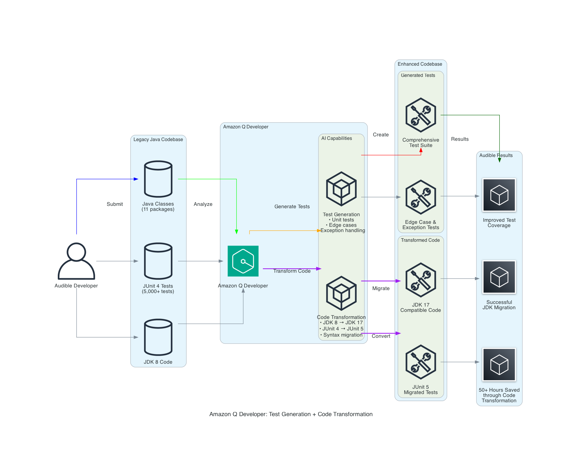
The Amazon Q Developer workflow demonstrates two key capabilities:
- Test Generation: Amazon Q Developer analyzes Java classes and creates comprehensive test suites including unit tests, edge case tests, and exception handling tests.
- Code Transformation: Amazon Q Developer performs automated migration tasks including
JDK 8toJDK 17/21upgrades, handling language version compatibility,JUnit 4toJUnit 5conversion, modernizing test framework syntax and annotations, syntax migration, updating deprecated APIs and code patterns.
What makes this workflow particularly powerful is how it combines AI capabilities with human expertise, allowing expert developers to leverage AI in their day-to-day workflow. Amazon Q Developer analyzes your codebase and uses it as a context, identifies edge cases, and performs automated transformations, while developers apply their domain knowledge to ensure the outputs align with business requirements and expected behavior.
Audible’s Approach to harness the potential of Amazon Q Developer
The Audible teams followed the below steps to harness Amazon Q Developer to boost test coverage.
Code Submission: The Audible team leveraged Amazon Q Developer to enhance their test coverage by generating additional unit tests for Java classes, including static methods and methods with existing test cases. This approach complemented their robust testing strategy. Amazon Q Developer has the ability to examine classes, methods, parameters, return types, and exceptions. Amazon Q Developer is helpful in automatically identifying unit tests to cover edge cases that can easily be overlooked, such as null input checks and empty string checks.
Targeted Requests: The Audible team specifically asked Amazon Q Developer to provide:
- Suggestions for unit tests to cover the given method within a Java class
- Recommendations for unit tests targeting untested edge cases
- Recommendations for test cases addressing error handling and exception scenarios
The Audible team achieved significant improvements using Amazon Q Developer for both test generation and code transformation. The key to their success was providing rich context along with targeted prompts in a systematic workflow.
Developer Workflow
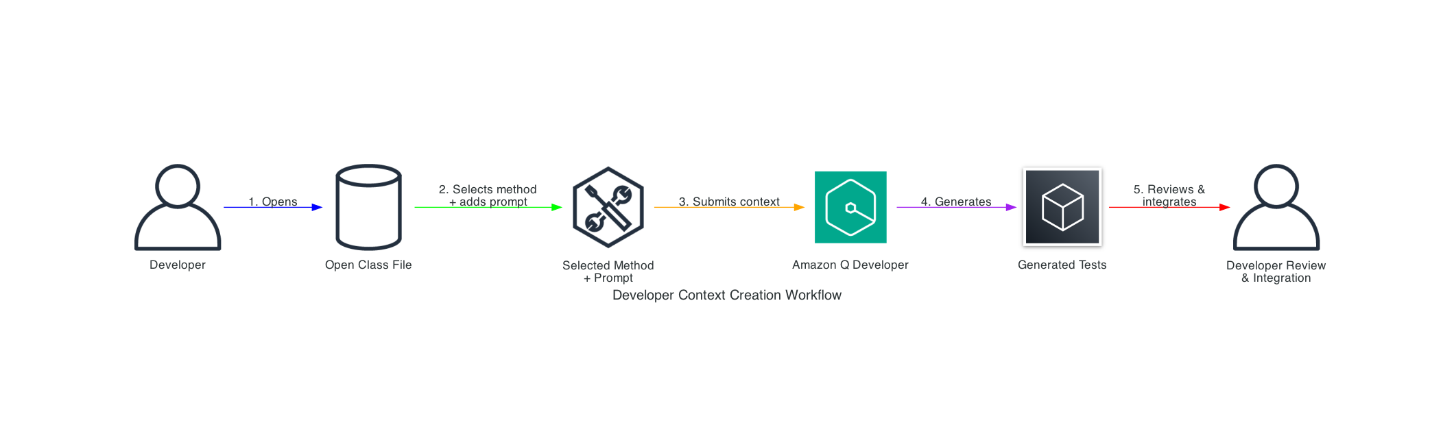
Audible adopts a human in the loop approach to review the output from automation tools. The above workflow shows the complete process: (1) open a class file in their IDE, (2) select a specific method and add their prompt, (3) submit this combined context to Amazon Q Developer, (4) receive generated tests, and (5) review and integrate the tests into their codebase.
Effective Prompts and Approach
The Audible team followed a structured approach, using targeted requests that Amazon Q Developer could act upon:
Code Submission: The team provided Java classes to Amazon Q Developer with code to generate tests for individual methods, including static methods and those that already had some tests but lacked full coverage. Amazon Q Developer examined classes, methods, parameters, return types, and exceptions, automatically identifying unit tests to cover edge cases like null input checks and empty string checks.
Below are generic Sample Prompts for Specific Requests:
Basic Test Generation:
Generate unit tests for the following Java method. Focus on covering all possible input scenarios and edge cases:

[method code here]

Please include tests for:
- Valid input scenarios
- Null input checks
- Empty string validations
- Exception handling
Edge Case Focus:
I have this method that processes user input. Can you suggest unit tests that cover edge cases I might have missed? Pay special attention to boundary conditions and error scenarios:

[method code here]
Manual Framework Migration (via Q Developer Chat):
Convert this JUnit 4 test to JUnit 5 format. Make sure to update annotations and use modern JUnit 5 features where appropriate:

[JUnit 4 test code here]
Note: While Amazon Q Developer’s code transformation feature can handle
JUnit4toJUnit5migration automatically across entire codebases, Audible also used the conversational interface for manual, targeted conversions as shown above. Both approaches are available. Refer to documentation for automated transformation details.
Test Generation: Based on the team’s requests, Amazon Q Developer generated specific test suggestions addressing these areas with appropriate assertions and test methods.
Implementation: The development team implemented the suggested tests after review.
Documentation: Amazon Q Developer has the ability to add comments to explain the purpose of the test, area of the functionality that the test is covering. In addition, Amazon Q Developer also has the ability to generate documentation related to other aspects like read-me files and project documentation.
Quantifiable Results
By leveraging Amazon Q Developer, the Audible team achieved:
- Over 10 key packages received comprehensive unit test coverage
- ~1 hour saved per test class (typically containing 8-10 individual tests)
- 5,000+ test cases successfully migrated from
JUnit4toJUnit5using both Amazon Q Developer’s code transformation and manual conversational assistance - 50+ hours of manual work saved during the
JDK8toJDK17migration using Amazon Q Developer’s code transformation - Reduced human errors through AI-assisted transformations
Key Capabilities Demonstrated
Amazon Q Developer excelled in several areas that can be overlooked in manual testing:
Comprehensive Exception Testing: Beyond standard null input checks and empty string validations, it automatically suggested tests for IllegalArgumentException, NullPointerException, and custom business exceptions, including verification of both exception throwing and specific error messages. This systematic approach made test coverage more complete and error handling more robust.
Automated Edge Case Detection: Amazon Q Developer made inline suggestions for null pointer exception handling without prompting, making the process smoother and faster.
Manual Framework Migration with AI Assistance: Amazon Q Developer’s pattern recognition accelerated the migration process through conversational assistance. The team could ask Amazon Q Developer through the chat to convert test syntax from JUnit4 to JUnit5 manually. For example, their previous setup had JUnit4 syntax with @UseDataProvider and @DataProvider annotations. All they had to do was highlight the code block, Send to Prompt, and ask Amazon Q Developer to make the test JUnit5 compatible. Within seconds, it generated a reliable JUnit5 test with ParameterizedTest annotation and Stream of Arguments that they could manually implement.
Contextual Analysis: Amazon Q Developer analyzes the existing codebase and recognized patterns and generated tests that matched the team’s coding style and testing conventions.
Conclusion
Amazon Q Developer transforms the test generation process from a time-consuming chore into a streamlined workflow, enabling teams to achieve comprehensive test coverage with minimal effort. This allows developers to focus on higher-value activities while improving code quality and reliability.
The business impact is substantial: As testing becomes less burdensome, teams naturally adopt better testing practices, creating a positive feedback loop that enhances overall code quality, and creates an opportunity for faster development cycles, and reduced time spent on maintenance.
To learn more about Amazon Q Developer’s features and pricing details, visit the Amazon Q Developer product page.
About the Authors

Kirankumar Chandrashekar is a Generative AI Specialist Solutions Architect at AWS, focusing on Next Generation Developer Experience tools like Q Developer, Kiro and Developer Productivity using AI. Bringing deep expertise in AWS cloud services, DevOps, modernization, and infrastructure as code, he helps customers accelerate their development cycles and elevate developer productivity through innovative AI-powered solutions. By leveraging Amazon Q Developer, he enables teams to build applications faster, automate routine tasks, and streamline development workflows. Kirankumar is dedicated to enhancing developer efficiency while solving complex customer challenges, and enjoys music, cooking, and traveling.

Alex Torres is a Senior Solutions Architect at AWS, supporting Amazon.com in architecting, designing, and building applications on AWS. With deep expertise in security, governance, and Agentic AI for developers, he helps customers leverage cutting-edge cloud technology to create products that shape people’s lives. Passionate about empowering teams to solve complex challenges through innovative AWS solutions, Alex is dedicated to driving customer success while maintaining the highest standards of security and governance. Outside of work, he enjoys cooking and hiking.

GK is a Senior Customer Solutions Manager and strategic customer advisor supporting Amazon as a customer of AWS. Over her four years at AWS, she has focused on improving developer productivity and advocating for Amazon’s needs across AWS services to enhance user experience and drive deeper alignment between the two organizations. Her work with advanced Amazon teams helps deliver solutions that ultimately benefit both internal and external AWS customers. GK is particularly interested in how GenAI is bridging the gap between developers and non-developers, and she spends much of her time solving challenges in GenAI and security. She is based in the San Francisco Bay Area and enjoys hiking and camping.

Aditi Joshi is a Software Engineer at Audible, working on expanding Audible’s presence across Amazon platforms. As a full-stack developer, she primarily works with web technologies, cloud services, and programming languages like JavaScript and Java to build and enhance cross-platform integration features, including recent projects like introducing Audible purchase capabilities in the Amazon iOS app. With expertise in user interface development, responsive design, and web technologies, she focuses on showcasing Audible offers and growing Audible’s visibility across Amazon’s ecosystem. Aditi is passionate about software architecture and user experience, focusing on building scalable systems with clean, efficient code. When not coding, Aditi enjoys traveling, practicing yoga, and listening to music.

Sam Park is a Software Development Engineer at Audible, focused on building Audible features across Amazon platforms. He has played a key role in enabling Audible purchases through Amazon Cart, as well as expanding Audible’s visibility within the Amazon iOS and Android apps. His work spans multiple touchpoints within the Amazon ecosystem, including Search, Product pages, Checkout, and Cart experiences. Sam is passionate about developing solutions that create intuitive customer experiences and leveraging GenAI to boost development efficiency and productivity. Outside of work, he enjoys traveling, playing basketball, and cheering on the Cleveland Cavaliers.


 Stella Hie is a Sr. Product Manager Technical for AWS Infrastructure as Code. She focuses on proactive control and governance space, working on delivering the best experience for customers to use AWS solutions safely. Outside of work, she enjoys hiking, playing piano, and watching live shows.


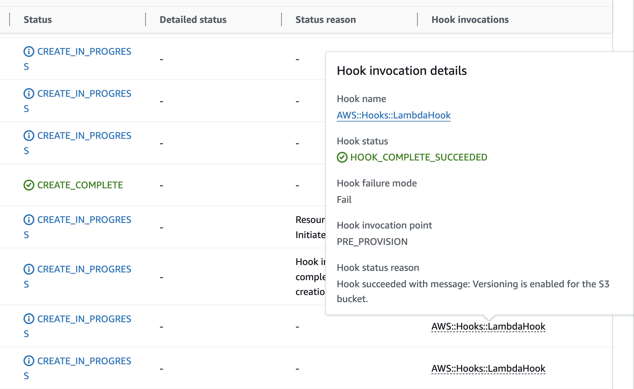
 Diagram 4: S3 Bucket creation success with hooks execution