Post Syndicated from Zaidoon Abd Al Hadi original http://blog.cloudflare.com/rethinking-cache-purge-architecture/

In Part 1: Rethinking Cache Purge, Fast and Scalable Global Cache Invalidation, we outlined the importance of cache invalidation and the difficulties of purging caches, how our existing purge system was designed and performed, and we gave a high level overview of what we wanted our new Cache Purge system to look like.
It’s been a while since we published the first blog post and it’s time for an update on what we’ve been working on. In this post we’ll be talking about some of the architecture improvements we’ve made so far and what we’re working on now.
Cache Purge end to end
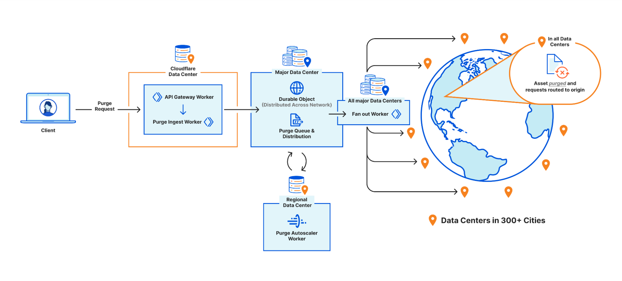
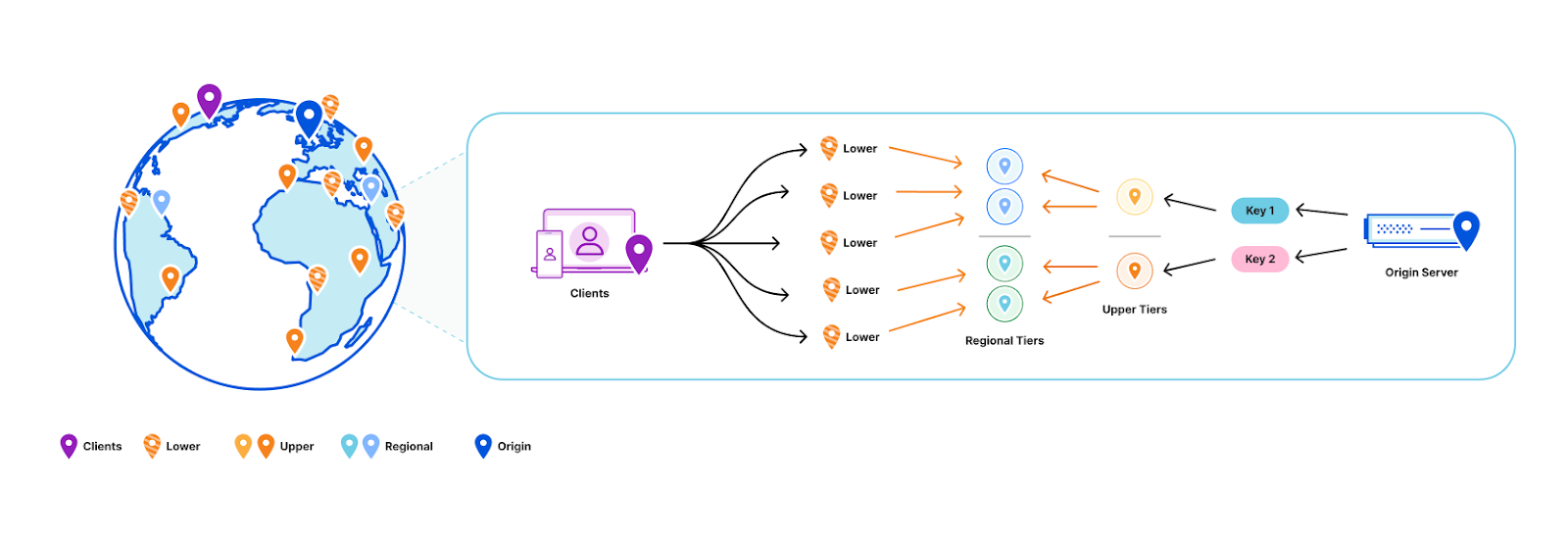
We touched on the high level design of what we called the “coreless” purge system in part 1, but let’s dive deeper into what that design encompasses by following a purge request from end to end:
Step 1: Request received locally
An API request to Cloudflare is routed to the nearest Cloudflare data center and passed to an API Gateway worker. This worker looks at the request URL to see which service it should be sent to and forwards the request to the appropriate upstream backend. Most endpoints of the Cloudflare API are currently handled by centralized services, so the API Gateway worker is often just proxying requests to the nearest “core” data center which have their own gateway services to handle authentication, authorization, and further routing. But for endpoints which aren’t handled centrally the API Gateway worker must handle authentication and route authorization, and then proxy to an appropriate upstream. For cache purge requests that upstream is a Purge Ingest worker in the same data center.
Step 2: Purges tested locally
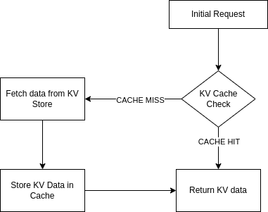
The Purge Ingest worker evaluates the purge request to make sure it is processible. It scans the URLs in the body of the request to see if they’re valid, then attempts to purge the URLs from the local data center’s cache. This concept of local purging was a new step introduced with the coreless purge system allowing us to capitalize on existing logic already used in every data center.
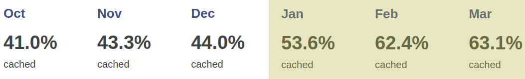
By leveraging the same ownership checks our data centers use to serve a zone’s normal traffic on the URLs being purged, we can determine if those URLs are even cacheable by the zone. Currently more than 50% of the URLs we’re asked to purge can’t be cached by the requesting zones, either because they don’t own the URLs (e.g. a customer asking us to purge https://cloudflare.com) or because the zone’s settings for the URL prevent caching (e.g. the zone has a “bypass” cache rule that matches the URL). All such purges are superfluous and shouldn’t be processed further, so we filter them out and avoid broadcasting them to other data centers freeing up resources to process more legitimate purges.
On top of that, generating the cache key for a file isn’t free; we need to load zone configuration options that might affect the cache key, apply various transformations, et cetera. The cache key for a given file is the same in every data center though, so when we purge the file locally we now return the generated cache key to the Purge Ingest worker and broadcast that key to other data centers instead of making each data center generate it themselves.
Step 3: Purges queued for broadcasting
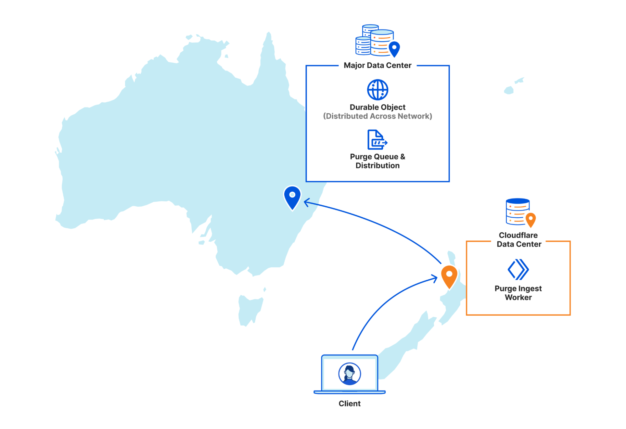
Once the local purge is done the Purge Ingest worker forwards the purge request with the cache key obtained from the local cache to a Purge Queue worker. The queue worker is a Durable Object worker using its persistent state to hold a queue of purges it receives and pointers to how far along in the queue each data center in our network is in processing purges.
The queue is important because it allows us to automatically recover from a number of scenarios such as connectivity issues or data centers coming back online after maintenance. Having a record of all purges since an issue arose lets us replay those purges to a data center and “catch up”.
But Durable Objects are globally unique, so having one manage all global purges would have just moved our centrality problem from a core data center to wherever that Durable Object was provisioned. Instead we have dozens of Durable Objects in each region, and the Purge Ingest worker looks at the load balancing pool of Durable Objects for its region and picks one (often in the same data center) to forward the request to. The Durable Object will write the purge request to its queue and immediately loop through all the data center pointers and attempt to push any outstanding purges to each.
While benchmarking our performance we found our particular workload exhibited a “goldilocks zone” of throughput to a given Durable Object. On script startup we have to load all sorts of data like network topology and data center health–then refresh it continuously in the background–and as long as the Durable Object sees steady traffic it stays active and we amortize those startup costs. But if you ask a single Durable Object to do too much at once like send or receive too many requests, the single-threaded runtime won’t keep up. Regional purge traffic fluctuates a lot depending on local time of day, so there wasn’t a static quantity of Durable Objects per region that would let us stay within the goldilocks zone of enough requests to each to keep them active but not too many to keep them efficient. So we built load monitoring into our Durable Objects, and a Regional Autoscaler worker to aggregate that data and adjust load balancing pools when we start approaching the upper or lower edges of our efficiency goldilocks zone.
Step 4: Purges broadcast globally
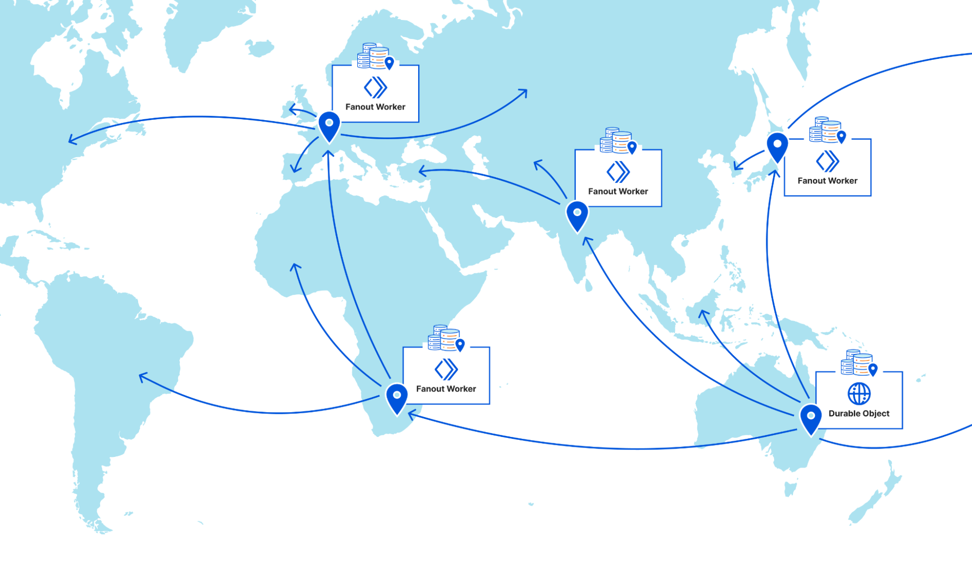
Once a purge request is queued by a Purge Queue worker it needs to be broadcast to the rest of Cloudflare’s data centers to be carried out by their caches. The Durable Objects will broadcast purges directly to all data centers in their region, but when broadcasting to other regions they pick a Purge Fanout worker per region to take care of their region’s distribution. The fanout workers manage queues of their own as well as pointers for all of their region’s data centers, and in fact they share a lot of the same logic as the Purge Queue workers in order to do so. One key difference is fanout workers aren’t Durable Objects; they’re normal worker scripts, and their queues are purely in memory as opposed to being backed by Durable Object state. This means not all queue worker Durable Objects are talking to the same fanout worker in each region. Fanout workers can be dropped and spun up again quickly by any metal in the data center because they aren’t canonical sources of state. They maintain queues and pointers for their region but all of that info is also sent back downstream to the Durable Objects who persist that data themselves, reliably.
But what does the fanout worker get us? Cloudflare has hundreds of data centers all over the world, and as we mentioned above we benefit from keeping the number of incoming and outgoing requests for a Durable Object fairly low. Sending purges to a fanout worker per region means each Durable Object only has to make a fraction of the requests it would if it were broadcasting to every data center directly, which means it can process purges faster.
On top of that, occasionally a request will fail to get where it was going and require retransmission. When this happens between data centers in the same region it’s largely unnoticeable, but when a Durable Object in Canada has to retry a request to a data center in rural South Africa the cost of traversing that whole distance again is steep. The data centers elected to host fanout workers have the most reliable connections in their regions to the rest of our network. This minimizes the chance of inter-regional retries and limits the latency imposed by retries to regional timescales.
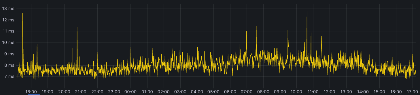
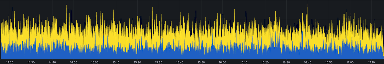
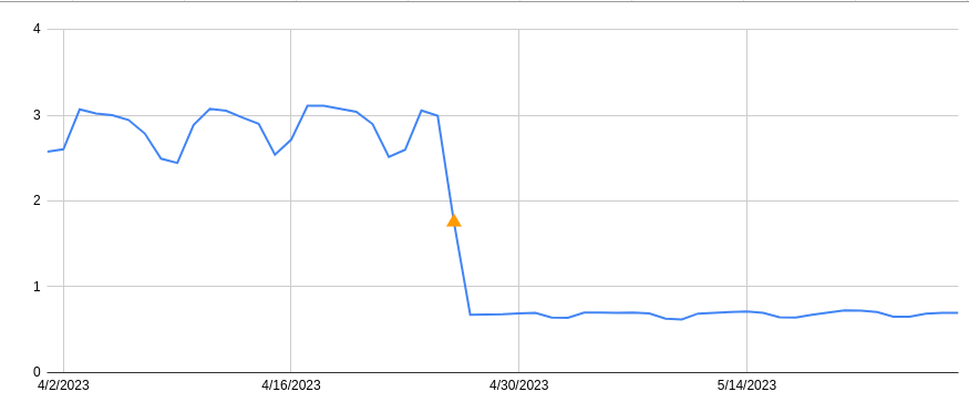
The introduction of the Purge Fanout worker was a massive improvement to our distribution system, reducing our end-to-end purge latency by 50% on its own and increasing our throughput threefold.
Current status of coreless purge
We are proud to say our new purge system has been in production serving purge by URL requests since July 2022, and the results in terms of latency improvements are dramatic. In addition, flexible purge requests (purge by tag/prefix/host and purge everything) share and benefit from the new coreless purge system’s entrypoint workers before heading to a core data center for fulfillment.
The reason flexible purge isn’t also fully coreless yet is because it’s a more complex task than “purge this object”; flexible purge requests can end up purging multiple objects–or even entire zones–from cache. They do this through an entirely different process that isn’t coreless compatible, so to make flexible purge fully coreless we would have needed to come up with an entirely new multi-purge mechanism on top of redesigning distribution. We chose instead to start with just purge by URL so we could focus purely on the most impactful improvements, revamping distribution, without reworking the logic a data center uses to actually remove an object from cache.
This is not to say that the flexible purges haven’t benefited from the coreless purge project. Our cache purge API lets users bundle single file and flexible purges in one request, so the API Gateway worker and Purge Ingest worker handle authorization, authentication and payload validation for flexible purges too. Those flexible purges get forwarded directly to our services in core data centers pre-authorized and validated which reduces load on those core data center auth services. As an added benefit, because authorization and validity checks all happen at the edge for all purge types users get much faster feedback when their requests are malformed.
Next steps
While coreless cache purge has come a long way since the part 1 blog post, we’re not done. We continue to work on reducing end-to-end latency even more for purge by URL because we can do better. Alongside improvements to our new distribution system, we’ve also been working on the redesign of flexible purge to make it fully coreless, and we’re really excited to share the results we’re seeing soon. Flexible cache purge is an incredibly popular API and we’re giving its refresh the care and attention it deserves.


")


 Chaitanya Shah is a Sr. Technical Account Manager(TAM) with AWS, based out of New York. He has over 22 years of experience working with enterprise customers. He loves to code and actively contributes to the AWS solutions labs to help customers solve complex problems. He provides guidance to AWS customers on best practices for their AWS Cloud migrations. He is also specialized in AWS data transfer and the data and analytics domain.