Tag Archives: AWS Step Functions

Introducing AWS X-Ray new integration with AWS Step Functions

Post Syndicated from Benjamin Smith original https://aws.amazon.com/blogs/compute/introducing-aws-x-ray-new-integration-with-aws-step-functions/

AWS Step Functions now integrates with AWS X-Ray to provide a comprehensive tracing experience for serverless orchestration workflows.

Step Functions allows you to build resilient serverless orchestration workflows with AWS services such as AWS Lambda, Amazon SNS, Amazon DynamoDB, and more. Step Functions provides a history of executions for a given state machine in the AWS Management Console or with Amazon CloudWatch Logs.

AWS X-Ray is a distributed tracing system that helps developers analyze and debug their applications. It traces requests as they travel through the individual services and resources that make up an application. This provides an end-to-end view of how an application is performing.

What is new?

The new Step Functions integration with X-Ray provides an additional workflow monitoring experience. Developers can now view maps and timelines of the underlying components that make up a Step Functions workflow. This helps to discover performance issues, detect permission problems, and track requests made to and from other AWS services.

The Step Functions integration with X-Ray can be analyzed in three constructs:

Service map: The service map view shows information about a Step Functions workflow and all of its downstream services. This enables developers to identify services where errors are occurring, connections with high latency, or traces for requests that are unsuccessful among the large set of services within their account. The service map aggregates data from specific time intervals from one minute through six hours and has a 30-day retention.

Trace map view: The trace map view shows in-depth information from a single trace as it moves through each service. Resources are listed in the order in which they are invoked.

Trace timeline: The trace timeline view shows the propagation of a trace through the workflow and is paired with a time scale called a latency distribution histogram. This shows how long it takes for a service to complete its requests. The trace is composed of segments and sub-segments. A segment represents the Step Functions execution. Subsegments each represent a state transition.

Getting Started

X-Ray tracing is enabled using AWS Serverless Application Model (AWS SAM), AWS CloudFormation or from within the AWS Management Console. To get started with Step Functions and X-Ray using the AWS Management Console:

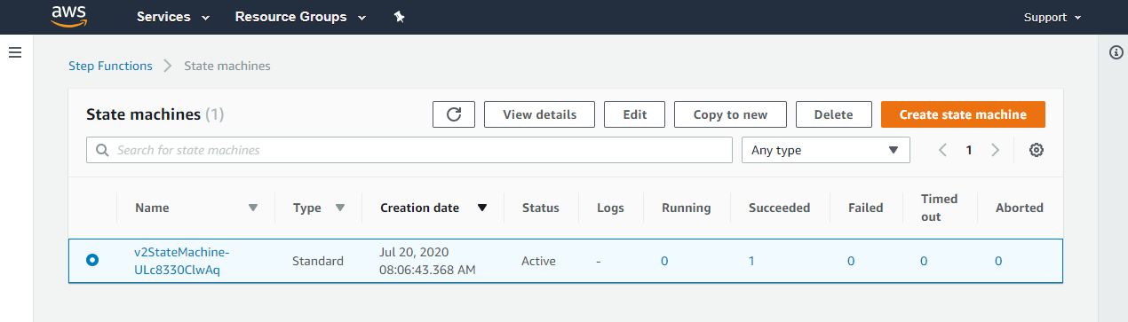
  1. Go to the Step Functions page of the AWS Management Console.
  2. Choose Get Started, review the Hello World example, then choose Next.
  3. Check Enable X-Ray tracing from the Tracing section.

Workflow visibility

The following Step Functions workflow example is invoked via Amazon EventBridge when a new file is uploaded to an Amazon S3 bucket. The workflow uses Amazon Textract to detect text from an image file. It translates the text into multiple languages using Amazon Translate and saves the results into an Amazon DynamoDB table. X-Ray has been enabled for this workflow.

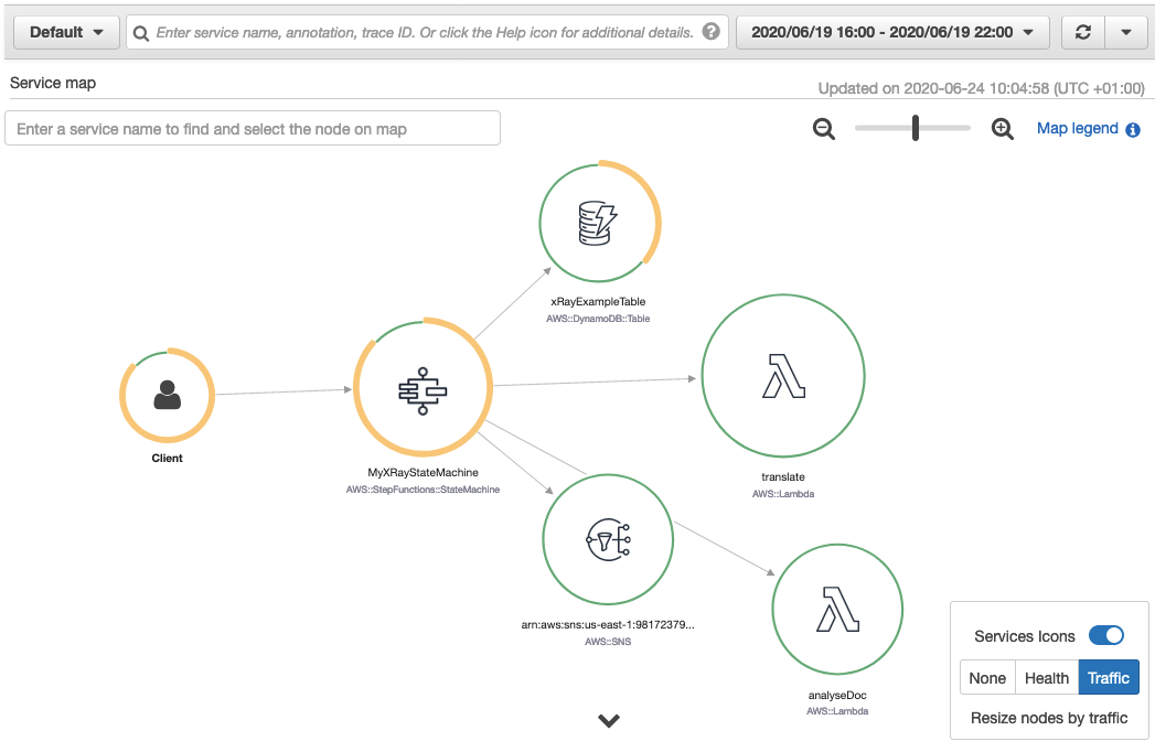
To view the X-Ray service map for this workflow, I choose the X-Ray trace map link at the top of the Step Functions Execution details page:

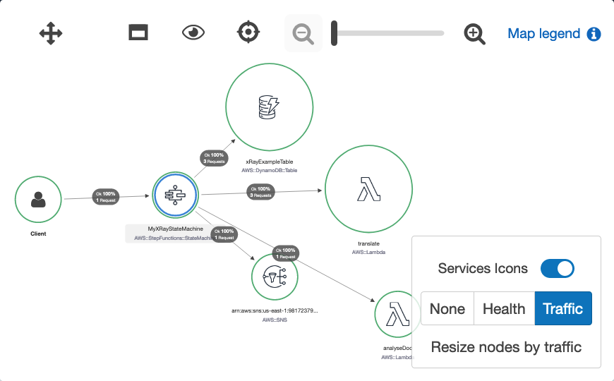
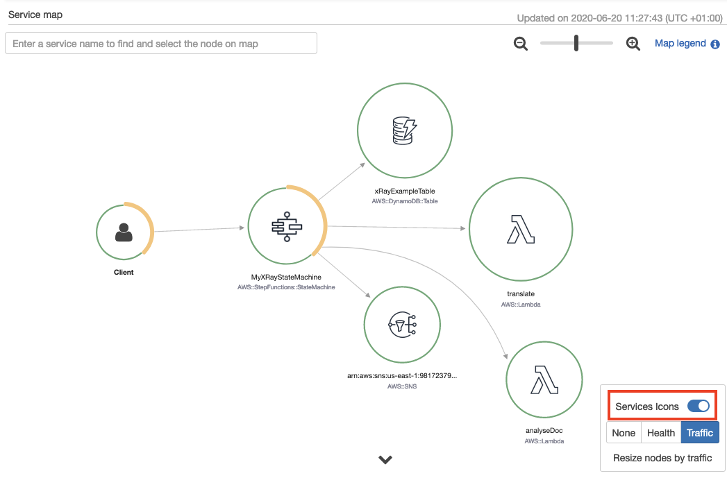
The service map is generated from trace data sent through the workflow. Toggling the Service Icons displays each individual service in this workload. The size of each node is weighted by traffic or health, depending on the selection.

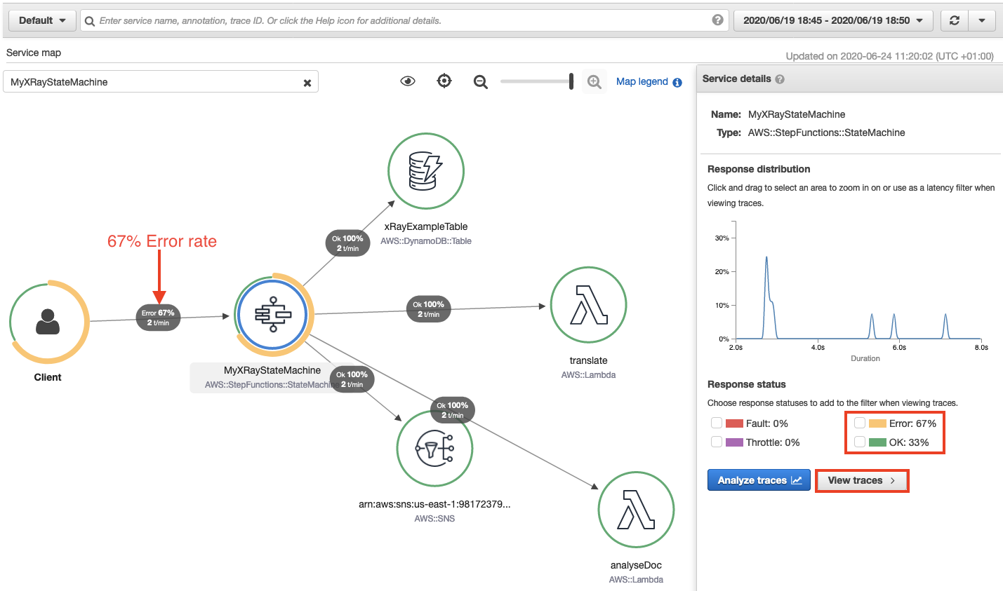
This shows the error percentage and average response times for each downstream service. T/min is the number of traces sent per minute in the selected time range. The following map shows a 67% error rate for the Step Functions workflow.

Accelerated troubleshooting

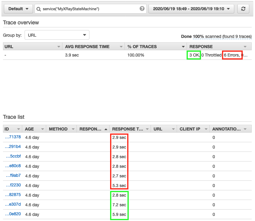
By drilling down through the service map, to the individual trace map, I quickly pinpoint the error in this workflow. I choose the Step Functions service from the trace map. This opens the service details panel. I then choose View traces. The trace data shows that from a group of nine responses, 3 completed successfully and 6 completed with error. This correlates with the response times listed for each individual trace. Three traces complete in over 5 seconds, while 6 took less than 3 seconds.

Choosing one of the faster traces opens the trace timeline map. This illustrates the aggregate response time for the workflow and each of its states. It shows a state named Read text from image invoked by a Lambda Function. This takes 2.3 seconds of the workflow’s total 2.9 seconds to complete.

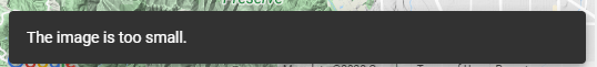
A warning icon indicates that an error has occurred in this Lambda function. Hovering the curser over the icon, reveals that the property “Blocks” is undefined. This shows that an error occurred within the Lambda function (no text was found within the image). The Lambda function did not have sufficient error handling to manage this error gracefully, so the workflow exited.

Here’s how that same state execution failure looks in the Step Functions Graph inspector.

Performance profiling

The visualizations provided in the service map are useful for estimating the average latency in a workflow, but issues are often indicated by statistical outliers. To help investigate these, the Response distribution graph shows a distribution of latencies for each state within a workflow, and its downstream services.

Latency is the amount of time between when a request starts and when it completes. It shows duration on the x-axis, and the percentage of requests that match each duration on the y-axis. Additional filters are applied to find traces by duration or status code. This helps to discover patterns and to identify specific cases and clients with issues at a given percentile.

Sampling

X-Ray applies a sampling algorithm to determine which requests to trace. A sampling rate of 100% is used for state machines with an execution rate of less than one per second. State machines running at a rate greater than one execution per second default to a 5% sampling rate. Configure the sampling rate to determine what percentage of traces to sample. Enable trace sampling with the AWS Command Line Interface (AWS CLI) using the CreateStateMachine and UpdateStateMachine APIs with the enable-Trace-Sampling attribute:

--enable-trace-sampling true

It can also be configured in the AWS Management Console.

Trace data retention and limits

X-Ray retains tracing data for up to 30 days with a single trace holding up to 7 days of execution data. The current minimum guaranteed trace size is 100Kb, which equates to approximately 80 state transitions.   The actual number of state transitions supported will depend on the upstream and downstream calls and duration of the workflow. When the trace size limit is reached, the trace cannot be updated with new segments or updates to existing segments. The traces that have reached the limit are indicated with a banner in the X-Ray console.

For a full service comparison of X-Ray trace data and Step Functions execution history, please refer to the documentation.

Conclusion

The Step Functions integration with X-Ray provides a single monitoring dashboard for workflows running at scale. It provides a high-level system overview of all workflow resources and the ability to drill down to view detailed timelines of workflow executions. You can now use the orchestration capabilities of Step Functions with the tracing, visualization, and debug capabilities of AWS X-Ray.

This enables developers to reduce problem resolution times by visually identifying errors in resources and viewing error rates across workflow executions. You can profile and improve application performance by identifying outliers while analyzing and debugging high latency and jitter in workflow executions.

This feature is available in all Regions where both AWS Step Functions and AWS X-Ray are available. View the AWS Regions table to learn more. For pricing information, see AWS X-Ray pricing.

To learn more about Step Functions, read the Developer Guide. For more serverless learning resources, visit https://serverlessland.com.

Introducing larger state payloads for AWS Step Functions

Post Syndicated from Rob Sutter original https://aws.amazon.com/blogs/compute/introducing-larger-state-payloads-for-aws-step-functions/

AWS Step Functions allows you to create serverless workflows that orchestrate your business processes. Step Functions stores data from workflow invocations as application state. Today we are increasing the size limit of application state from 32,768 characters to 256 kilobytes of data per workflow invocation. The new limit matches payload limits for other commonly used serverless services such as Amazon SNS, Amazon SQS, and Amazon EventBridge. This means you no longer need to manage Step Functions payload limitations as a special case in your serverless applications.

Faster, cheaper, simpler state management

Previously, customers worked around limits on payload size by storing references to data, such as a primary key, in their application state. An AWS Lambda function then loaded the data via an SDK call at runtime when the data was needed. With larger payloads, you now can store complete objects directly in your workflow state. This removes the need to persist and load data from data stores such as Amazon DynamoDB and Amazon S3. You do not pay for payload size, so storing data directly in your workflow may reduce both cost and execution time of your workflows and Lambda functions. Storing data in your workflow state also reduces the amount of code you need to write and maintain.

AWS Management Console and workflow history improvements

Larger state payloads mean more data to visualize and search. To help you understand that data, we are also introducing changes to the AWS Management Console for Step Functions. We have improved load time for the Execution History page to help you get the information you need more quickly. We have also made backwards-compatible changes to the GetExecutionHistory API call. Now if you set includeExecutionData to false, GetExecutionHistory excludes payload data and returns only metadata. This allows you to debug your workflows more quickly.

Doing more with dynamic parallelism

A larger payload also allows your workflows to process more information. Step Functions workflows can process an arbitrary number of tasks concurrently using dynamic parallelism via the Map State. Dynamic parallelism enables you to iterate over a collection of related items applying the same process to each item. This is an implementation of the map procedure in the MapReduce programming model.

When to choose dynamic parallelism

Choose dynamic parallelism when performing operations on a small collection of items generated in a preliminary step. You define an Iterator, which operates on these items individually. Optionally, you can reduce the results to an aggregate item. Unlike with parallel invocations, each item in the collection is related to the other items. This means that an error in processing one item typically impacts the outcome of the entire workflow.

Example use case

Ecommerce and line of business applications offer many examples where dynamic parallelism is the right approach. Consider an order fulfillment system that receives an order and attempts to authorize payment. Once payment is authorized, it attempts to lock each item in the order for shipment. The available items are processed and their total is taken from the payment authorization. The unavailable items are marked as pending for later processing.

The following Amazon States Language (ASL) defines a Map State with a simplified Iterator that implements the order fulfillment steps described previously.


    "Map": {
      "Type": "Map",
      "ItemsPath": "$.orderItems",
      "ResultPath": "$.packedItems",
      "MaxConcurrency": 40,
      "Next": "Print Label",
      "Iterator": {
        "StartAt": "Lock Item",
        "States": {
          "Lock Item": {
            "Type": "Pass",
            "Result": "Item locked!",
            "Next": "Pull Item"
          },
          "Pull Item": {
            "Type": "Pass",
            "Result": "Item pulled!",
            "Next": "Pack Item"
          },
          "Pack Item": {
            "Type": "Pass",
            "Result": "Item packed!",
            "End": true
          }
        }
      }
    }

The following image provides a visualization of this workflow. A preliminary state retrieves the collection of items from a data store and loads it into the state under the orderItems key. The triple dashed lines represent the Map State which attempts to lock, pull, and pack each item individually. The result of processing each individual item impacts the next state, Print Label. As more items are pulled and packed, the total weight increases. If an item is out of stock, the total weight will decrease.

A visualization of a portion of an AWS Step Functions workflow that implements dynamic parallelism

Dynamic parallelism or the “Map State”

Larger state payload improvements

Without larger state payloads, each item in the $.orderItems object in the workflow state would be a primary key to a specific item in a DynamoDB table. Each step in the “Lock, Pull, Pack” workflow would need to read data from DynamoDB for every item in the order to access detailed item properties.

With larger state payloads, each item in the $.orderItems object can be a complete object containing the required fields for the relevant items. Not only is this faster, resulting in a better user experience, but it also makes debugging workflows easier.

Pricing and availability

Larger state payloads are available now in all commercial and AWS GovCloud (US) Regions where Step Functions is available. No changes to your workflows are required to use larger payloads, and your existing workflows will continue to run as before. The larger state is available however you invoke your Step Functions workflows, including the AWS CLI, the AWS SDKs, the AWS Step Functions Data Science SDK, and Step Functions Local.

Larger state payloads are included in existing Step Functions pricing for Standard Workflows. Because Express Workflows are priced by runtime and memory, you may see more cost on individual workflows with larger payloads. However, this increase may also be offset by the reduced cost of Lambda, DynamoDB, S3, or other AWS services.

Conclusion

Larger Step Functions payloads simplify and increase the efficiency of your workflows by eliminating function calls to persist and retrieve data. Larger payloads also allow your workflows to process more data concurrently using dynamic parallelism.

With larger payloads, you can minimize the amount of custom code you write and focus on the business logic of your workflows. Get started building serverless workflows today!

Using serverless backends to iterate quickly on web apps – part 3

Post Syndicated from James Beswick original https://aws.amazon.com/blogs/compute/using-serverless-backends-to-iterate-quickly-on-web-apps-part-3/

This series is about building flexible backends for web applications. The example is Happy Path, a web app that allows park visitors to upload and share maps and photos, to help replace printed materials.

In part 1, I show how the application works and walk through the backend architecture. In part 2, you deploy a basic image-processing workflow. To do this, you use an AWS Serverless Application Model (AWS SAM) template to create an AWS Step Functions state machine.

In this post, I show how to deploy progressively more complex workflow functionality while using minimal code. This solution in this web app is designed for 100,000 monthly active users. Using this approach, you can introduce more sophisticated workflows without affecting the existing backend application.

The code and instructions for this application are available in the GitHub repo.

Introducing image moderation

In the first version, users could upload any images to parks on the map. One of the most important feature requests is to enable moderation, to prevent inappropriate images from appearing on the app. To handle a large number of uploaded images, using human moderation would be slow and labor-intensive.

In this section, you use Amazon ML services to automate analyzing the images for unsafe content. Amazon Rekognition provides an API to detect if an image contains moderation labels. These labels are categorized into different types of unsafe content that would not be appropriate for this app.

Version 2 of the workflow uses this API to automate the process of checking images. To install version 2:

  1. From a terminal window, delete the v1 workflow stack:
    aws cloudformation delete-stack --stack-name happy-path-workflow-v1
  2. Change directory to the version 2 AWS SAM template in the repo:
    cd .\workflows\templates\v2
  3. Build and deploy the solution:
    sam build
    sam deploy --guided
  4. The deploy process prompts you for several parameters. Enter happy-path-workflow-v2 as the Stack Name. The other values are the outputs from the backend deployment process, detailed in the repo’s README. Enter these to complete the deployment.

From VS Code, open the v2 state machine in the repo from workflows/statemachines/v2.asl.json. Choose the Render graph option in the CodeLens to see the workflow visualization.

Serverless workflow visualization

This new workflow introduces a Moderator step. This invokes a Moderator Lambda function that uses the Amazon Rekognition API. If this API identifies any unsafe content labels, it returns these as part of the function output.

The next step in the workflow is a Moderation result choice state. This evaluates the output of the previous function – if the image passes moderation, the process continues to the Resizer function. If it fails, execution moves to the RecordFailState step.

Step Functions integrates directly with some AWS services so that you can call and pass parameters into the APIs of those services. The RecordFailState uses an Amazon DynamoDB service integration to write the workflow failure to the application table, using the arn:aws:states:::dynamodb:updateItem resource.

Testing the workflow

To test moderation, I use an unsafe image with suggestive content. This is an image that is not considered appropriate for this application. To test the deployed v2 workflow:

  1. Open the frontend application at https://localhost:8080 in your browser.
  2. Select a park location, choose Show Details, and then choose Upload images.
  3. Select an unsafe image to upload.
  4. Navigate to the Step Functions console. This shows the v2StateMachine with one successful execution:State machine result
  5. Select the state machine, and choose the execution to display more information. Scroll down to the Visual workflow panel.Visual workflow panel

This shows that the moderation failed and the path continued to log the failed state in the database. If you open the Output resource, this displays more details about why the image is considered unsafe.

Checking the image size and file type

The upload component in the frontend application limits file selection to JPG images but there is no check to reject images that are too small. It’s prudent to check and enforce image types and sizes on the backend API in addition to the frontend. This is because it’s possible to upload images via the API without using the frontend.

The next version of the workflow enforces image sizes and file types. To install version 3:

  1. From a terminal window, delete the v2 workflow stack:
    aws cloudformation delete-stack --stack-name happy-path-workflow-v2
  2. Change directory to the version 3 AWS SAM template in the repo:
    cd .\workflows\templates\v3
  3. Build and deploy the solution:
    sam build
    sam deploy --guided
  4. The deploy process prompts you for several parameters. Enter happy-path-workflow-v3 as the Stack Name. The other values are the outputs from the backend deployment process, detailed in the repo’s README. Enter these to complete the deployment.

From VS Code, open the v3 state machine in the repo from workflows/statemachines/v3.asl.json. Choose the Render graph option in the CodeLens to see the workflow visualization.

v3 state machine

This workflow changes the starting point of the execution, introducing a Check Dimensions step. This invokes a Lambda function that checks the size and types of the Amazon S3 object using the image-size npm package. This function uses environment variables provided by the AWS SAM template to compare against a minimum size and allowed type array.

The output is evaluated by the Dimension Result choice state. If the image is larger than the minimum size allowed, execution continues to the Moderator function as before. If not, it passes to the RecordFailState step to log the result in the database.

Testing the workflow

To test, I use an image that’s narrower than the mixPixels value. To test the deployed v3 workflow:

  1. Open the frontend application at https://localhost:8080 in your browser.
  2. Select a park location, choose Show Details, and then choose Upload images.
  3. Select an image with a width smaller than 800 pixels. After a few seconds, a rejection message appears:"Image is too small" message
  4. Navigate to the Step Functions console. This shows the v3StateMachine with one successful execution. Choose the execution to show more detail.Execution output

The execution shows that the Check Dimension step added the image dimensions to the event object. Next, the Dimensions Result choice state rejected the image, and logged the result at the RecordFailState step. The application’s DynamoDB table now contains details about the failed upload:

DynamoDB item details

Pivoting the application to a new concept

Until this point, the Happy Path web application is designed to help park visitors share maps and photos. This is the development team’s original idea behind the app. During the product-market fit stage of development, it’s common for applications to pivot substantially from the original idea. For startups, it can be critical to have the agility to modify solutions quickly to meet the needs of customers.

In this scenario, the original idea has been less successful than predicted, and park visitors are not adopting the app as expected. However, the business development team has identified a new opportunity. Restaurants would like an app that allows customers to upload menus and food photos. How can the development team create a new proof-of-concept app for restaurant customers to test this idea?

In this version, you modify the application to work for restaurants. While features continue to be added to the parks workflow, it now supports business logic specifically for the restaurant app.

To create the v4 workflow and update the frontend:

  1. From a terminal window, delete the v3 workflow stack:
    aws cloudformation delete-stack --stack-name happy-path-workflow-v3
  2. Change directory to the version 4 AWS SAM template in the repo:
    cd .\workflows\templates\v4
  3. Build and deploy the solution:
    sam build
    sam deploy --guided
  4. The deploy process prompts you for several parameters. Enter happy-path-workflow-v4 as the Stack Name. The other values are the outputs from the backend deployment process, detailed in the repo’s README. Enter these to complete the deployment.
  5. Open frontend/src/main.js and update the businessType variable on line 63. Set this value to ‘restaurant’.Change config to restaurants
  6. Start the local development server:
    npm run serve
  7. Open the application at http://localhost:8080. This now shows restaurants in the local area instead of parks.

In the Step Functions console, select the v4StateMachine to see the latest workflow, then open the Definition tab to see the visualization:

Workflow definition

This workflow starts with steps that apply to both parks and restaurants – checking the image dimensions. Next, it determines the place type from the placeId record in DynamoDB. Depending on place type, it now follows a different execution path:

  • Parks continue to run the automated moderator process, then resizer and publish the result.
  • Restaurants now use Amazon Rekognition to determine the labels in the image. Any photos containing people are rejected. Next, the workflow continues to the resizer and publish process.
  • Other business types go to the RecordFailState step since they are not supported.

Testing the workflow

To test the deployed v4 workflow:

  1. Open the frontend application at https://localhost:8080 in your browser.
  2. Select a restaurant, choose Show Details, and then choose Upload images.
  3. Select an image from the test photos dataset. After a few seconds, you see a message confirming the photo has been added.
  4. Next, select an image that contains one or more people. The new restaurant workflow rejects this type of photo:"Image rejected" message
  5. In the Step Functions console, select the last execution for the v4StateMachine to see how the Check for people step rejected the image:v4 workflow

If other business types are added later to the application, you can extend the Step Functions workflow accordingly. The cost of Step Functions is based on the number of transitions in a workflow, not the number of total steps. This means you can branch by business type in the Happy Path application. This doesn’t affect the overall cost of running an execution, if the total transitions are the same per execution.

Conclusion

Previously in this series, you deploy a simple workflow for processing image uploads in the Happy Path web application. In this post, you add progressively more complex functionality by deploying new versions of workflows.

The first iteration introduces image moderation using Amazon Rekognition, providing the ability to automate the evaluation of unsafe content. Next, the workflow is modified to check image size and file type. This allows you to reject any images that are too small or do not meet the type requirements. Finally, I show how to expand the logic further to accept other business types with their own custom workflows.

To learn more about building serverless web applications, see the Ask Around Me series.

Building storage-first serverless applications with HTTP APIs service integrations

Post Syndicated from Eric Johnson original https://aws.amazon.com/blogs/compute/building-storage-first-applications-with-http-apis-service-integrations/

Over the last year, I have been talking about “storage first” serverless patterns. With these patterns, data is stored persistently before any business logic is applied. The advantage of this pattern is increased application resiliency. By persisting the data before processing, the original data is still available, if or when errors occur.

Common pattern for serverless API backend

Common pattern for serverless API backend

Using Amazon API Gateway as a proxy to an AWS Lambda function is a common pattern in serverless applications. The Lambda function handles the business logic and communicates with other AWS or third-party services to route, modify, or store the processed data. One option is to place the data in an Amazon Simple Queue Service (SQS) queue for processing downstream. In this pattern, the developer is responsible for handling errors and retry logic within the Lambda function code.

The storage first pattern flips this around. It uses native error handling with retry logic or dead-letter queues (DLQ) at the SQS layer before any code is run. By directly integrating API Gateway to SQS, developers can increase application reliability while reducing lines of code.

Storage first pattern for serverless API backend

Storage first pattern for serverless API backend

Previously, direct integrations require REST APIs with transformation templates written in Velocity Template Language (VTL). However, developers tell us they would like to integrate directly with services in a simpler way without using VTL. As a result, HTTP APIs now offers the ability to directly integrate with five AWS services without needing a transformation template or code layer.

The first five service integrations

This release of HTTP APIs direct integrations includes Amazon EventBridge, Amazon Kinesis Data Streams, Simple Queue Service (SQS), AWS System Manager’s AppConfig, and AWS Step Functions. With these new integrations, customers can create APIs and webhooks for their business logic hosted in these AWS services. They can also take advantage of HTTP APIs features like authorizers, throttling, and enhanced observability for securing and monitoring these applications.

Amazon EventBridge

HTTP APIs service integration with Amazon EventBridge

HTTP APIs service integration with Amazon EventBridge

The HTTP APIs direct integration for EventBridge uses the PutEvents API to enable client applications to place events on an EventBridge bus. Once the events are on the bus, EventBridge routes the event to specific targets based upon EventBridge filtering rules.

This integration is a storage first pattern because data is written to the bus before any routing or logic is applied. If the downstream target service has issues, then EventBridge implements a retry strategy with incremental back-off for up to 24 hours. Additionally, the integration helps developers reduce code by filtering events at the bus. It routes to downstream targets without the need for a Lambda function as a transport layer.

Use this direct integration when:

  • Different tasks are required based upon incoming event details
  • Only data ingestion is required
  • Payload size is less than 256 kb
  • Expected requests per second are less than the Region quotas.

Amazon Kinesis Data Streams

HTTP APIs service integration with Amazon Kinesis Data Streams

HTTP APIs service integration with Amazon Kinesis Data Streams

The HTTP APIs direct integration for Kinesis Data Streams offers the PutRecord integration action, enabling client applications to place events on a Kinesis data stream. Kinesis Data Streams are designed to handle up to 1,000 writes per second per shard, with payloads up to 1 mb in size. Developers can increase throughput by increasing the number of shards in the data stream. You can route the incoming data to targets like an Amazon S3 bucket as part of a data lake or a Kinesis data analytics application for real-time analytics.

This integration is a storage first option because data is stored on the stream for up to seven days until it is processed and routed elsewhere. When processing stream events with a Lambda function, errors are handled at the Lambda layer through a configurable error handling strategy.

Use this direct integration when:

  • Ingesting large amounts of data
  • Ingesting large payload sizes
  • Order is important
  • Routing the same data to multiple targets

Amazon SQS

HTTP APIs service integration with Amazon SQS

HTTP APIs service integration with Amazon SQS

The HTTP APIs direct integration for Amazon SQS offers the SendMessage, ReceiveMessage, DeleteMessage, and PurgeQueue integration actions. This integration differs from the EventBridge and Kinesis integrations in that data flows both ways. Events can be created, read, and deleted from the SQS queue via REST calls through the HTTP API endpoint. Additionally, a full purge of the queue can be managed using the PurgeQueue action.

This pattern is a storage first pattern because the data remains on the queue for four days by default (configurable to 14 days), unless it is processed and removed. When the Lambda service polls the queue, the messages that are returned are hidden in the queue for a set amount of time. Once the calling service has processed these messages, it uses the DeleteMessage API to remove the messages permanently.

When triggering a Lambda function with an SQS queue, the Lambda service manages this process internally. However, HTTP APIs direct integration with SQS enables developers to move this process to client applications without the need for a Lambda function as a transport layer.

Use this direct integration when:

  • Data must be received as well as sent to the service
  • Downstream services need reduced concurrency
  • The queue requires custom management
  • Order is important (FIFO queues)

AWS AppConfig

HTTP APIs service integration with AWS Systems Manager AppConfig

HTTP APIs service integration with AWS Systems Manager AppConfig

The HTTP APIs direct integration for AWS AppConfig offers the GetConfiguration integration action and allows applications to check for application configuration updates. By exposing the systems parameter API through an HTTP APIs endpoint, developers can automate configuration changes for their applications. While this integration is not considered a storage first integration, it does enable direct communication from external services to AppConfig without the need for a Lambda function as a transport layer.

Use this direct integration when:

  • Access to AWS AppConfig is required.
  • Managing application configurations.

AWS Step Functions

HTTP APIs service integration with AWS Step Functions

HTTP APIs service integration with AWS Step Functions

The HTTP APIs direct integration for Step Functions offers the StartExecution and StopExecution integration actions. These actions allow for programmatic control of a Step Functions state machine via an API. When starting a Step Functions workflow, JSON data is passed in the request and mapped to the state machine. Error messages are also mapped to the state machine when stopping the execution.

This pattern provides a storage first integration because Step Functions maintains a persistent state during the life of the orchestrated workflow. Step Functions also supports service integrations that allow the workflows to send and receive data without needing a Lambda function as a transport layer.

Use this direct integration when:

  • Orchestrating multiple actions.
  • Order of action is required.

Building HTTP APIs direct integrations

HTTP APIs service integrations can be built using the AWS CLI, AWS SAM, or through the API Gateway console. The console walks through contextual choices to help you understand what is required for each integration. Each of the integrations also includes an Advanced section to provide additional information for the integration.

Creating an HTTP APIs service integration

Creating an HTTP APIs service integration

Once you build an integration, you can export it as an OpenAPI template that can be used with infrastructure as code (IaC) tools like AWS SAM. The exported template can also include the API Gateway extensions that define the specific integration information.

Exporting the HTTP APIs configuration to OpenAPI

Exporting the HTTP APIs configuration to OpenAPI

OpenAPI template

An example of a direct integration from HTTP APIs to SQS is located in the Sessions With SAM repository. This example includes the following architecture:

AWS SAM template resource architecture

AWS SAM template resource architecture

The AWS SAM template creates the HTTP APIs, SQS queue, Lambda function, and both Identity and Access Management (IAM) roles required. This is all generated in 58 lines of code and looks like this:

AWSTemplateFormatVersion: '2010-09-09'
Transform: AWS::Serverless-2016-10-31
Description: HTTP API direct integrations

Resources:
  MyQueue:
    Type: AWS::SQS::Queue
    
  MyHttpApi:
    Type: AWS::Serverless::HttpApi
    Properties:
      DefinitionBody:
        'Fn::Transform':
          Name: 'AWS::Include'
          Parameters:
            Location: './api.yaml'
          
  MyHttpApiRole:
    Type: "AWS::IAM::Role"
    Properties:
      AssumeRolePolicyDocument:
        Version: "2012-10-17"
        Statement:
          - Effect: "Allow"
            Principal:
              Service: "apigateway.amazonaws.com"
            Action: 
              - "sts:AssumeRole"
      Policies:
        - PolicyName: ApiDirectWriteToSQS
          PolicyDocument:
            Version: '2012-10-17'
            Statement:
              Action:
              - sqs:SendMessage
              Effect: Allow
              Resource:
                - !GetAtt MyQueue.Arn
                
  MyTriggeredLambda:
    Type: AWS::Serverless::Function
    Properties:
      CodeUri: src/
      Handler: app.lambdaHandler
      Runtime: nodejs12.x
      Policies:
        - SQSPollerPolicy:
            QueueName: !GetAtt MyQueue.QueueName
      Events:
        SQSTrigger:
          Type: SQS
          Properties:
            Queue: !GetAtt MyQueue.Arn

Outputs:
  ApiEndpoint:
    Description: "HTTP API endpoint URL"
    Value: !Sub "https://${MyHttpApi}.execute-api.${AWS::Region}.amazonaws.com"

The OpenAPI template handles the route definitions for the HTTP API configuration and configures the service integration. The template looks like this:

openapi: "3.0.1"
info:
  title: "my-sqs-api"
paths:
  /:
    post:
      responses:
        default:
          description: "Default response for POST /"
      x-amazon-apigateway-integration:
        integrationSubtype: "SQS-SendMessage"
        credentials:
          Fn::GetAtt: [MyHttpApiRole, Arn]
        requestParameters:
          MessageBody: "$request.body.MessageBody"
          QueueUrl:
            Ref: MyQueue
        payloadFormatVersion: "1.0"
        type: "aws_proxy”
        connectionType: "INTERNET"
x-amazon-apigateway-importexport-version: "1.0"

Because the OpenAPI template is included in the AWS SAM template via a transform, the API Gateway integration can reference the roles and services created within the AWS SAM template.

Conclusion

This post covers the concept of storage first integration patterns and how the new HTTP APIs direct integrations can help. I cover the five current integrations and possible use cases for each. Additionally, I demonstrate how to use AWS SAM to build and manage the integrated applications using infrastructure as code.

Using the storage first pattern with direct integrations can help developers build serverless applications that are more durable with fewer lines of code. A Lambda function is no longer required to transport data from the API endpoint to the desired service. Instead, use Lambda function invocations for differentiating business logic.

To learn more join us for the HTTP API service integrations session of Sessions With SAM! 

#ServerlessForEveryone

Fundbox: Simplifying Ways to Query and Analyze Data by Different Personas

Post Syndicated from Annik Stahl original https://aws.amazon.com/blogs/architecture/fundbox-simplifying-ways-to-query-and-analyze-data-by-different-personas/

Fundbox is a leading technology platform focused on disrupting the $21 trillion B2B commerce market by building the world’s first B2B payment and credit network. With Fundbox, sellers of all sizes can quickly increase average order volumes (AOV) and improve close rates by offering more competitive net terms and payment plans to their SMB buyers. With heavy investments in machine learning and the ability to quickly analyze the transactional data of SMB’s, Fundbox is reimagining B2B payments and credit products in new category-defining ways.

Learn how how the company simplified the way different personas in the organization query and analyze data by building a self-service data orchestration platform. The platform architecture is entirely serverless, which simplifies the ability to scale and adopt to unpredictable demand. The platform was built using AWS Step Functions, AWS Lambda, Amazon API Gateway, Amazon DynamoDB, AWS Fargate, and other AWS Serverless managed services.

For more content like this, subscribe to our YouTube channels This is My Architecture, This is My Code, and This is My Model, or visit the This is My Architecture on AWS, which has search functionality and the ability to filter by industry, language, and service.

Using serverless backends to iterate quickly on web apps – part 2

Post Syndicated from James Beswick original https://aws.amazon.com/blogs/compute/using-serverless-backends-to-iterate-quickly-on-web-apps-part-2/

This series is about building flexible solutions that can adapt as user requirements change. One of the challenges of building modern web applications is that requirements can change quickly. This is especially true for new applications that are finding their product-market fit. Many development teams start building a product with one set of requirements, and quickly find they must build a product with different features.

For both start-ups and enterprises, it’s often important to find a development methodology and architecture that allows flexibility. This is the surest way to keep up with feature requests in evolving products and innovate to delight your end-users. In this post, I show how to build sophisticated workflows using minimal custom code.

Part 1 introduces the Happy Path application that allows park visitors to share maps and photos with other users. In that post, I explain the functionality, how to deploy the application, and walk through the backend architecture.

The Happy Path application accepts photo uploads from users’ smartphones. The application architecture must support 100,000 monthly active users. These binary uploads are typically 3–9 MB in size and must be resized and optimized for efficient distribution.

Using a serverless approach, you can develop a robust low-code solution that can scale to handle millions of images. Additionally, the solution shown here is designed to handle complex changes that are introduced in subsequent versions of the software. The code and instructions for this application are available in the GitHub repo.

Architecture overview

After installing the backend in the previous post, the architecture looks like this:

In this design, the API, storage, and notification layers exist as one application, and the business logic layer is a separate application. These two applications are deployed using AWS Serverless Application Model (AWS SAM) templates. This architecture uses Amazon EventBridge to pass events between the two applications.

In the business logic layer:

  1. The workflow starts when events are received from EventBridge. Each time a new object is uploaded by an end-user, the PUT event in the Amazon S3 Upload bucket triggers this process.
  2. After the workflow is completed successfully, processed images are stored in the Distribution bucket. Related metadata for the object is also stored in the application’s Amazon DynamoDB table.

By separating the architecture into two independent applications, you can replace the business logic layer as needed. Providing that the workflow accepts incoming events and then stores processed images in the S3 bucket and DynamoDB table, the workflow logic becomes interchangeable. Using the pattern, this workflow can be upgraded to handle new functionality.

Introducing AWS Step Functions for workflow management

One of the challenges in building distributed applications is coordinating components. These systems are composed of separate services, which makes orchestrating workflows more difficult than working with a single monolithic application. As business logic grows more complex, if you attempt to manage this in custom code, it can become quickly convoluted. This is especially true if it handles retries and error handling logic, and it can be hard to test and maintain.

AWS Step Functions is designed to coordinate and manage these workflows in distributed serverless applications. To do this, you create state machine diagrams using Amazon States Language (ASL). Step Functions renders a visualization of your state machine, which makes it simpler to see the flow of data from one service to another.

Each state machine consists of a series of steps. Each step takes an input and produces an output. Using ASL, you define how this data progresses through the state machine. The flow from step to step is called a transition. All state machines transition from a Start state towards an End state.

The Step Functions service manages the state of individual executions. The service also supports versioning, which makes it easier to modify state machines in production systems. Executions continue to use the version of a state machine when they were started, so it’s possible to have active executions on multiple versions.

For developers using VS Code, the AWS Toolkit extension provides support for writing state machines using ASL. It also renders visualizations of those workflows. Combined with AWS Serverless Application Model (AWS SAM) templates, this provides a powerful way to deploy and maintain applications based on Step Functions. I refer to this IDE and AWS SAM in this walkthrough.

Version 1: Image resizing

The Happy Path application uses Step Functions to manage the image-processing part of the backend. The first version of this workflow resizes the uploaded image.

To see this workflow:

  1. In VS Code, open the workflows/statemachines folder in the Explorer panel.
  2. Choose the v1.asl.sjon file.v1 state machine
  3. Choose the Render graph option in the CodeLens. This opens the workflow visualization.CodeLens - Render graph

In this basic workflow, the state machine starts at the Resizer step, then progresses to the Publish step before ending:

  • In the top-level attributes in the definition, StartsAt sets the Resizer step as the first action.
  • The Resizer step is defined as a task with an ARN of a Lambda function. The Next attribute determines that the Publish step is next.
  • In the Publish step, this task defines a Lambda function using an ARN reference. It sets the input payload as the entire JSON payload. This step is set as the End of the workflow.

Deploying the Step Functions workflow

To deploy the state machine:

  1. In the terminal window, change directory to the workflows/templates/v1 folder in the repo.
  2. Execute these commands to build and deploy the AWS SAM template:
    sam build
    sam deploy –guided
  3. The deploy process prompts you for several parameters. Enter happy-path-workflow-v1 as the Stack Name. The other values are the outputs from the backend deployment process, detailed in the repo’s README. Enter these to complete the deployment.
  4. SAM deployment output

Testing and inspecting the deployed workflow

Now the workflow is deployed, you perform an integration test directly from the frontend application.

To test the deployed v1 workflow:

  1. Open the frontend application at https://localhost:8080 in your browser.
  2. Select a park location, choose Show Details, and then choose Upload images.
  3. Select an image from the sample photo dataset.
  4. After a few seconds, you see a pop-up message confirming that the image has been added:Upload confirmation message
  5. Select the same park location again, and the information window now shows the uploaded image:Happy Path - park with image data

To see how the workflow processed this image:

  1. Navigate to the Steps Functions console.
  2. Here you see the v1StateMachine with one execution in the Succeeded column.Successful execution view
  3. Choose the state machine to display more information about the start and end time.State machine detail
  4. Select the execution ID in the Executions panel to open details of this single instance of the workflow.

This view shows important information that’s useful for understanding and debugging an execution. Under Input, you see the event passed into Step Functions by EventBridge:

Event detail from EventBridge

This contains detail about the S3 object event, such as the bucket name and key, together with the placeId, which identifies the location on the map. Under Output, you see the final result from the state machine, shows a successful StatusCode (200) and other metadata:

Event output from the state machine

Using AWS SAM to define and deploy Step Functions state machines

The AWS SAM template defines both the state machine, the trigger for executions, and the permissions needed for Step Functions to execute. The AWS SAM resource for a Step Functions definition is AWS::Serverless::StateMachine.

Definition permissions in state machines

In this example:

  • DefinitionUri refers to an external ASL definition, instead of embedding the JSON in the AWS SAM template directly.
  • DefinitionSubstitutions allow you to use tokens in the ASL definition that refer to resources created in the AWS SAM template. For example, the token ${ResizerFunctionArn} refers to the ARN of the resizer Lambda function.
  • Events define how the state machine is invoked. Here it defines an EventBridge rule. If an event matches this source and detail-type, it triggers an execution.
  • Policies: the Step Functions service must have permission to invoke the services that perform tasks in the state machine. AWS SAM policy templates provide a convenient shorthand for common execution policies, such as invoking a Lambda function.

This workflow application is separate from the main backend template. As more functionality is added to the workflow, you deploy the subsequent AWS SAM templates in the same way.

Conclusion

Using AWS SAM, you can specify serverless resources, configure permissions, and define substitutions for the ASL template. You can deploy a standalone Step Functions-based application using the AWS SAM CLI, separately from other parts of your application. This makes it easier to decouple and maintain larger applications. You can visualize these workflows directly in the VS Code IDE in addition to the AWS Management Console.

In part 3, I show how to build progressively more complex workflows and how to deploy these in-place without affecting the other parts of the application.

To learn more about building serverless web applications, see the Ask Around Me series.