Tag Archives: AWS Step Functions

Automate Document Processing in Logistics using AI

Post Syndicated from Manikanth Pasumarti original https://aws.amazon.com/blogs/architecture/automate-document-processing-in-logistics-using-ai/

Multi-modal transportation is one of the biggest developments in the logistics industry. There has been a successful collaboration across different transportation partners in supply chain freight forwarding for many decades. But there’s still a considerable overhead of paperwork processing for each leg of the trip. Tens of billions of documents are processed in ocean freight forwarding alone. Using manual labor to process these documents (purchase orders, invoices, bills of lading, delivery receipts, and more) is both expensive and error-prone.

In this blog post, we’ll address how to automate the document processing in the logistics industry. We’ll also show you how to integrate it with a centralized workflow management.

Automated document processing architecture

Figure 1. Architecture of document processing workflow

Figure 1. Architecture of document processing workflow

The solution workflow shown in Figure 1 is as follows:

  1. Documents that belong to the same transaction are collected in an S3 bucket
  2. The document processing workflow is initiated
  3. The workflow orchestration is as follows:
    • Document is processed via automation
    • Relevant entities are extracted
    • Extracted data is reviewed
    • Order data is consolidated

This architecture uses Amazon Simple Storage Service (S3) for document storage, and Amazon Simple Queue Service (SQS) for workflow initiation. Amazon Textract is used for text extraction, Amazon Comprehend for entity extraction, and Amazon Augmented AI (A2I) for human review. This will ensure correct results in cases of low confidence predictions.

We use AWS Step Functions for the orchestration of document processing workflow. Step functions also help to improve the application resiliency with less code.

AWS Lambda functions are used to:

  • Detect if all required documents for a given transaction are available in Amazon S3
  • Kick off the process by creating an Amazon SQS message
  • Detect a new processing job from a generated SQS message
  • Extract text from PDFs using a Step Function
  • Extract entities from generated text using a Step Function
  • Control data completeness and accuracy
  • Initiate a human loop when needed using a Step Function
  • Consolidate the data collected from documents
  • Store the data into the database

Document ingestion and classification

There are several data ingestion options available such as AWS Transfer Family, AWS DataSync, and Amazon Kinesis Data Firehose. Choose the appropriate ingestion blueprints based on the type of data sources. Typical real-time ingestion blueprints include AWS Lambda processing and an Amazon CloudWatch event. The batch pipeline can leverage AWS Step Functions. This can be used to orchestrate the Lambda function that initiates the document processing workflow.

Here are some things to consider when building your document ingestion and storage solution:

  • Choose your bucket strategy. Amazon S3 is an object store. Analyze your data pipeline ingestion carefully and choose the correct S3 bucket strategy for each document type (bills, supplier invoices, and others.)
  • Organize your data. The data is organized in S3 buckets by layers: Raw, Staging, and Processed. Each has their own respective bucket policy and access control.
  • Build a creation tool. This is an automated data lake bucket/folder structure tool, based on your data ingestion requirements. You can use this same structure for user-created data.
  • Define data security requirements. Do this before you begin the ingestion process. Before ingesting new or current data sources into AWS, secure access to the data.
  • Review security credentials needed for access. After copying these credentials into AWS Systems Manager (SSM), apply an AWS Key Management Service (KMS) key to encrypt the file. This encrypted key string is stored in SSM to use for authentication.

Document processing workflow

Overview

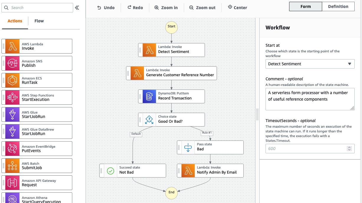
The workflow checks the input buckets until it detects all the documents types necessary for a complete dataset. In our case, it is the invoice document and customs authorization form. Once both are detected, it generates a job request as a message in Amazon SQS. A Lambda function then processes the message and kicks off the Step Function flow (see Figure 2). The state machine then initiates the document processing, text extraction, and optional human review steps. AWS Step Functions are well suited for our use case due to its ability to manage long-running workflows.

Figure 2. Visual workflow of document processing in AWS Step Functions

Figure 2. Visual workflow of document processing in AWS Step Functions

Entity extraction

For each document, entities are extracted using Amazon Textract and Amazon Comprehend. These entities can include date, company, address, bill of materials, total cost, and invoice number.

Following is a sample invoice document that is fed to Amazon Textract, which extracts the form data and creates key-value pairs.

Figure 3. Highlighted different entities in the sample invoice document

Figure 3. Highlighted different entities in the sample invoice document

See Figure 4 for an example of the key-value pairs extracted for the sample invoice. The keys here represent the form labels (“SHIP TO”) and the values represent form values (shipping address).

Figure 4. Key-value pairs of the invoice data, extracted by Amazon Textract

Figure 4. Key-value pairs of the invoice data, extracted by Amazon Textract

Amazon Textract also generates a raw text output that contains the entire text, as shown in Figure 5 following.

Figure 5. Raw text output of the invoice data extracted by Amazon Textract

Figure 5. Raw text output of the invoice data extracted by Amazon Textract

To achieve a higher degree of confidence, Amazon Comprehend is used to identify and extract the custom entities. Amazon Comprehend is a natural language processing (NLP) service that uses machine learning (ML) to identify and extracts insights and entities from text data. You can train Amazon Comprehend to identify entities relevant to your organization. These can be product names, part numbers, department names, or other entities. You can also train Amazon Comprehend to categorize documents or assign relevant labels to text.

An Amazon Comprehend entity recognizer comes with a set of pre-built entity types. Amazon Comprehend can introduce custom entities to match our specific business needs. Some of the entities we want to identify are address and company name. We trained a custom recognizer to detect company names and addresses, see Figure 6.

Figure 6. Training details of custom entity recognizer

Figure 6. Training details of custom entity recognizer

Figure 7 shows the resulting output from Amazon Comprehend:

Figure 7. Amazon Comprehend entity recognition output

Figure 7. Amazon Comprehend entity recognition output

The document is processed top-down, from left to right, from the sample invoice in Figure 3. We know that the first company and first address belongs to the Billing Company. And the second set belongs to the Shipment recipient. Along with detecting custom entities, Amazon Comprehend also outputs the confidence score of the extracted result.

Confidence scores can vary depending on how close training data is to actual data. In the example preceding, the first company entity came back with a score of 0.941. Let’s assume that we have set a minimum confidence score of 0.95. Anything below that threshold should be reviewed by a human. The following section describes the last step of our workflow.

Human review

Amazon Augmented AI (A2I) allows you to create and manage human loops. A human loop is a manual review task that gets assigned to a workforce. The workforce can be public, such as Mechanical Turk, or private, such as internal team or a paid contractor. In our example, we created a private workforce to review the entities we were not confident about. Figure 8 shows an example of the user interface that the reviewers use to assign entities to the proper text sections.

Figure 8. Manual review interface of Amazon A2I

Figure 8. Manual review interface of Amazon A2I

Review tasks can be automatically submitted to the workforce based on dynamic criteria, after both AI-related steps are completed. It can be used to review the text detected by Amazon Textract when key data elements are missing (such as order amount or quantity). It can also review entities after invoking Amazon Comprehend.

Figure 9. Consolidated dataset of processed invoice and customs authorization data

Figure 9. Consolidated dataset of processed invoice and customs authorization data

After the manual review step, data can be consolidated (as shown in Figure 9) and stored into a relational database. It can also be shared with other business units such as Accounting or Customer Services. You can apply the same process to other document types such as custom forms, which are linked to the same transaction. This allows us to process and combine information that comes from disparate paper sources more efficiently.

Conclusion

This post demonstrates how document processing can be automated to process business documentation by using Amazon Textract, Amazon Comprehend and Amazon Augmented AI.

Deploying an automated solution in the logistics industry takes away the undifferentiated heavy lifting involved in manual document processing. This helps to cut down the delivery delays and track any missed deliveries. By providing a comprehensive view of the shipment, it increases the efficiency of back-office processing. It can also further simplify the data collection for audit purposes.

To learn more:

Building well-architected serverless applications: Building in resiliency – part 2

Post Syndicated from Julian Wood original https://aws.amazon.com/blogs/compute/building-well-architected-serverless-applications-building-in-resiliency-part-2/

This series of blog posts uses the AWS Well-Architected Tool with the Serverless Lens to help customers build and operate applications using best practices. In each post, I address the serverless-specific questions identified by the Serverless Lens along with the recommended best practices. See the introduction post for a table of contents and explanation of the example application.

Reliability question REL2: How do you build resiliency into your serverless application?

This post continues part 1 of this reliability question. Previously, I cover managing failures using retries, exponential backoff, and jitter. I explain how DLQs can isolate failed messages. I show how to use state machines to orchestrate long running transactions rather than handling these in application code.

Required practice: Manage duplicate and unwanted events

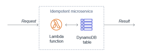
Duplicate events can occur when a request is retried or multiple consumers process the same message from a queue or stream. A duplicate can also happen when a request is sent twice at different time intervals with the same parameters. Design your applications to process multiple identical requests to have the same effect as making a single request.

Idempotency refers to the capacity of an application or component to identify repeated events and prevent duplicated, inconsistent, or lost data. This means that receiving the same event multiple times does not change the result beyond the first time the event was received. An idempotent application can, for example, handle multiple identical refund operations. The first refund operation is processed. Any further refund requests to the same customer with the same payment reference should not be processes again.

When using AWS Lambda, you can make your function idempotent. The function’s code must properly validate input events and identify if the events were processed before. For more information, see “How do I make my Lambda function idempotent?

When processing streaming data, your application must anticipate and appropriately handle processing individual records multiple times. There are two primary reasons why records may be delivered more than once to your Amazon Kinesis Data Streams application: producer retries and consumer retries. For more information, see “Handling Duplicate Records”.

Generate unique attributes to manage duplicate events at the beginning of the transaction

Create, or use an existing unique identifier at the beginning of a transaction to ensure idempotency. These identifiers are also known as idempotency tokens. A number of Lambda triggers include a unique identifier as part of the event:

You can also create your own identifiers. These can be business-specific, such as transaction ID, payment ID, or booking ID. You can use an opaque random alphanumeric string, unique correlation identifiers, or the hash of the content.

A Lambda function, for example can use these identifiers to check whether the event has been previously processed.

Depending on the final destination, duplicate events might write to the same record with the same content instead of generating a duplicate entry. This may therefore not require additional safeguards.

Use an external system to store unique transaction attributes and verify for duplicates

Lambda functions can use Amazon DynamoDB to store and track transactions and idempotency tokens to determine if the transaction has been handled previously. DynamoDB Time to Live (TTL) allows you to define a per-item timestamp to determine when an item is no longer needed. This helps to limit the storage space used. Base the TTL on the event source. For example, the message retention period for SQS.

Using DynamoDB to store idempotent tokens

Using DynamoDB to store idempotent tokens

You can also use DynamoDB conditional writes to ensure a write operation only succeeds if an item attribute meets one of more expected conditions. For example, you can use this to fail a refund operation if a payment reference has already been refunded. This signals to the application that it is a duplicate transaction. The application can then catch this exception and return the same result to the customer as if the refund was processed successfully.

Third-party APIs can also support idempotency directly. For example, Stripe allows you to add an Idempotency-Key: <key> header to the request. Stripe saves the resulting status code and body of the first request made for any given idempotency key, regardless of whether it succeeded or failed. Subsequent requests with the same key return the same result.

Validate events using a pre-defined and agreed upon schema

Implicitly trusting data from clients, external sources, or machines could lead to malformed data being processed. Use a schema to validate your event conforms to what you are expecting. Process the event using the schema within your application code or at the event source when applicable. Events not adhering to your schema should be discarded.

For API Gateway, I cover validating incoming HTTP requests against a schema in “Implementing application workload security – part 1”.

Amazon EventBridge rules match event patterns. EventBridge provides schemas for all events that are generated by AWS services. You can create or upload custom schemas or infer schemas directly from events on an event bus. You can also generate code bindings for event schemas.

SNS supports message filtering. This allows a subscriber to receive a subset of the messages sent to the topic using a filter policy. For more information, see the documentation.

JSON Schema is a tool for validating the structure of JSON documents. There are a number of implementations available.

Best practice: Consider scaling patterns at burst rates

Load testing your serverless application allows you to monitor the performance of an application before it is deployed to production. Serverless applications can be simpler to load test, thanks to the automatic scaling built into many of the services. For more information, see “How to design Serverless Applications for massive scale”.

In addition to your baseline performance, consider evaluating how your workload handles initial burst rates. This ensures that your workload can sustain burst rates while scaling to meet possibly unexpected demand.

Perform load tests using a burst strategy with random intervals of idleness

Perform load tests using a burst of requests for a short period of time. Also introduce burst delays to allow your components to recover from unexpected load. This allows you to future-proof the workload for key events when you do not know peak traffic levels.

There are a number of AWS Marketplace and AWS Partner Network (APN) solutions available for performance testing, including Gatling FrontLine, BlazeMeter, and Apica.

In regulating inbound request rates – part 1, I cover running a performance test suite using Gatling, an open source tool.

Gatling performance results

Gatling performance results

Amazon does have a network stress testing policy that defines which high volume network tests are allowed. Tests that purposefully attempt to overwhelm the target and/or infrastructure are considered distributed denial of service (DDoS) tests and are prohibited. For more information, see “Amazon EC2 Testing Policy”.

Review service account limits with combined utilization across resources

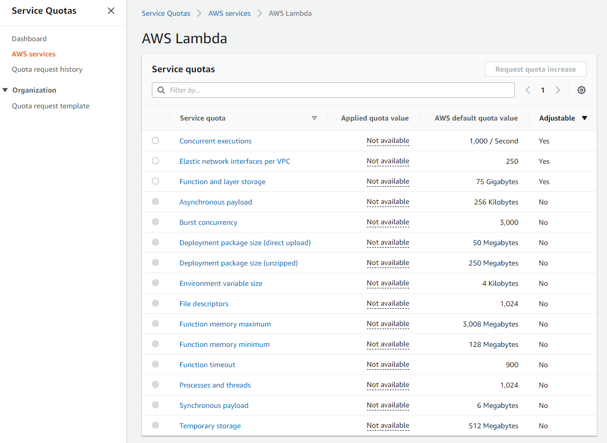
AWS accounts have default quotas, also referred to as limits, for each AWS service. These are generally Region-specific. You can request increases for some limits while other limits cannot be increased. Service Quotas is an AWS service that helps you manage your limits for many AWS services. Along with looking up the values, you can also request a limit increase from the Service Quotas console.

Service Quotas dashboard

Service Quotas dashboard

As these limits are shared within an account, review the combined utilization across resources including the following:

  • Amazon API Gateway: number of requests per second across all APIs. (link)
  • AWS AppSync: throttle rate limits. (link)
  • AWS Lambda: function concurrency reservations and pool capacity to allow other functions to scale. (link)
  • Amazon CloudFront: requests per second per distribution. (link)
  • AWS IoT Core message broker: concurrent requests per second. (link)
  • Amazon EventBridge: API requests and target invocations limit. (link)
  • Amazon Cognito: API limits. (link)
  • Amazon DynamoDB: throughput, indexes, and request rates limits. (link)

Evaluate key metrics to understand how workloads recover from bursts

There are a number of key Amazon CloudWatch metrics to evaluate and alert on to understand whether your workload recovers from bursts.

  • AWS Lambda: Duration, Errors, Throttling, ConcurrentExecutions, UnreservedConcurrentExecutions. (link)
  • Amazon API Gateway: Latency, IntegrationLatency, 5xxError, 4xxError. (link)
  • Application Load Balancer: HTTPCode_ELB_5XX_Count, RejectedConnectionCount, HTTPCode_Target_5XX_Count, UnHealthyHostCount, LambdaInternalError, LambdaUserError. (link)
  • AWS AppSync: 5XX, Latency. (link)
  • Amazon SQS: ApproximateAgeOfOldestMessage. (link)
  • Amazon Kinesis Data Streams: ReadProvisionedThroughputExceeded, WriteProvisionedThroughputExceeded, GetRecords.IteratorAgeMilliseconds, PutRecord.Success, PutRecords.Success (if using Kinesis Producer Library), GetRecords.Success. (link)
  • Amazon SNS: NumberOfNotificationsFailed, NumberOfNotificationsFilteredOut-InvalidAttributes. (link)
  • Amazon Simple Email Service (SES): Rejects, Bounces, Complaints, Rendering Failures. (link)
  • AWS Step Functions: ExecutionThrottled, ExecutionsFailed, ExecutionsTimedOut. (link)
  • Amazon EventBridge: FailedInvocations, ThrottledRules. (link)
  • Amazon S3: 5xxErrors, TotalRequestLatency. (link)
  • Amazon DynamoDB: ReadThrottleEvents, WriteThrottleEvents, SystemErrors, ThrottledRequests, UserErrors. (link)

Conclusion

This post continues from part 1 and looks at managing duplicate and unwanted events with idempotency and an event schema. I cover how to consider scaling patterns at burst rates by managing account limits and show relevant metrics to evaluate

Build resiliency into your workloads. Ensure that applications can withstand partial and intermittent failures across components that may only surface in production. In the next post in the series, I cover the performance efficiency pillar from the Well-Architected Serverless Lens.

For more serverless learning resources, visit Serverless Land.

Classifying Millions of Amazon items with Machine Learning, Part I: Event Driven Architecture

Post Syndicated from Mahmoud Abid original https://aws.amazon.com/blogs/architecture/classifying-millions-of-amazon-items-with-machine-learning-part-i-event-driven-architecture/

As part of AWS Professional Services, we work with customers across different industries to understand their needs and supplement their teams with specialized skills and experience.

Some of our customers are internal teams from the Amazon retail organization who request our help with their initiatives. One of these teams, the Global Environmental Affairs team, identifies the number of electronic products sold. Then they classify these products according to local laws and accurately report this data to regulators. This process covers the products’ end-of-life costs and ensures a high quality of recycling.

These electronic products have classification codes that differ from country to country, and these codes change according to each country’s latest regulations. This poses a complex technical problem. How do we automate our compliance teams’ work to efficiently and accurately classify over three million product classifications every month, in more than 38 countries, while also complying with evolving classification regulations?

To solve this problem, we used Amazon Machine Learning (Amazon ML) capabilities to build a resilient architecture. It ingests and processes data, trains ML models, and predicts (also known as inference workflow) monthly sales data for all countries concurrently.

In this post, we outline how we used AWS Lambda, Amazon EventBridge, and AWS Step Functions to build a scalable and cost-effective solution. We’ll also show you how to keep the data secure while processing it in Amazon ML flows.

Solution overview

Our solution consists of three main parts, which are summarized here and detailed in the following sections:

  1. Training the ML models
  2. Evaluating their performance
  3. Using them to run an inference workflow (in other words, label) the sold items with the correct classification codes

Training the Amazon ML model

For training our Amazon ML model, we use the architecture in Figure 1. It starts with a periodic query against the Amazon.com data warehouse in Amazon Redshift.

Training workflow

Figure 1. Training workflow

  1. A labeled dataset containing pre-recorded classification codes is extracted from Amazon Redshift. This dataset is stored in an Amazon Simple Storage Service (Amazon S3) bucket and split up by country. The data is encrypted at rest with server-side encryption using an AWS Key Management Service (AWS KMS) key. This is also known as server-side encryption with AWS KMS (SSE-KMS). The extraction query uses the AWS KMS key to encrypt the data when storing it in the S3 bucket.
  2. Each time a country’s dataset is uploaded to the S3 bucket, a message is sent to an Amazon Simple Queue Service (Amazon SQS) queue. This prompts a Lambda function. We use Amazon SQS to ensure resiliency. If the Lambda function fails, the message will be tried again automatically. Overall, the message is either processed successfully, or ends up in a dead letter queue that we monitor (not displayed in Figure 1).
  3. If the message is processed successfully, the Lambda function generates necessary input parameters. Then it starts a Step Functions workflow execution for the training process.
  4. The training process involves orchestrating Amazon SageMaker Processing jobs to prepare the data. Once the data is prepared, a hyperparameter optimization job invokes multiple training jobs. These run in parallel with different values from a range of hyperparameters. The model that performs the best is chosen to move forward.
  5. After the model is trained successfully, an EventBridge event is prompted, which will be used to invoke the performance comparison process.

Comparing performance of Amazon ML models

Because Amazon ML models are automatically trained periodically, we want to assess their performance automatically too. Newly created models should perform better than their predecessors. To measure this, we use the flow in Figure 2.

Model performance comparison workflow

Figure 2. Model performance comparison workflow

  1. The flow is activated by the EventBridge event at the end of the training flow.
  2. A Lambda function gathers the necessary input parameters and uses them to start an inference workflow, implemented as a Step Function.
  3. The inference workflow use SageMaker Processing jobs to prepare a new test dataset. It performs predictions using SageMaker Batch Transform jobs with the new model. The test dataset is a labeled subset that was not used in model training. Its prediction gives an unbiased estimation of the model’s performance, proving that the model can generalize.
  4. After the inference workflow is completed and the results are stored on Amazon S3, an EventBridge event is performed, which prompts another Lambda function. This function runs the performance comparison Step Function.
  5. The performance comparison workflow uses a SageMaker Processing job to analyze the inference results and calculate its performance score based on ground truth. For each country, the job compares the performance of the new model with the performance of the last used model to determine which one was best, otherwise known as the “winner model.” The metadata of the winner model is saved in an Amazon DynamoDB table so it can be queried and used in the next production inference job.
  6. At the end of the performance comparison flow, an informational notification is sent to an Amazon Simple Notification Service (Amazon SNS) topic, which will be received by the MLOps team.

Running inference

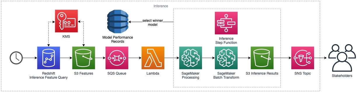
The inference flow starts with a periodic query against the Amazon.com data warehouse in Amazon Redshift, as shown in Figure 3.

Inference workflow

Figure 3. Inference workflow

  1. As with training, the dataset is extracted from Amazon Redshift, split up by country, and stored in an S3 bucket and encrypted at rest using the AWS KMS key.
  2. Every country dataset upload prompts a message to an SQS queue, which invokes a Lambda function.
  3. The Lambda function gathers necessary input parameters and starts a workflow execution for the inference process. This is the same Step Function we used in the performance comparison. Now it runs against the real dataset instead of the test set.
  4. The inference Step Function orchestrates the data preparation and prediction using the winner model for each country, as stored in the model performance DynamoDB table. The predictions are uploaded back to the S3 bucket to be further consumed for reporting.
  5. Lastly, an Amazon SNS message is sent to signal completion of the inference flow, which will be received by different stakeholders.

Data encryption

One of the key requirements of this solution was to provide least privilege access to all data. To achieve this, we use AWS KMS to encrypt all data as follows:

Restriction of data decryption permissions

Figure 4. Restriction of data decryption permissions

Conclusion

In this post, we outline how we used a serverless architecture to handle the end-to-end flow of data extraction, processing, and storage. We also talk about how we use this data for model training and inference.

With this solution, our customer team onboarded 38 countries and brought 60 Amazon ML models to production to classify 3.3 million items on a monthly basis.

In the next post, we show you how we use AWS Developer Tools to build a comprehensive continuous integration/continuous delivery (CI/CD) pipeline that safeguards the code behind this solution.


Building well-architected serverless applications: Building in resiliency – part 1

Post Syndicated from Julian Wood original https://aws.amazon.com/blogs/compute/building-well-architected-serverless-applications-building-in-resiliency-part-1/

This series of blog posts uses the AWS Well-Architected Tool with the Serverless Lens to help customers build and operate applications using best practices. In each post, I address the serverless-specific questions identified by the Serverless Lens along with the recommended best practices. See the introduction post for a table of contents and explanation of the example application.

Reliability question REL2: How do you build resiliency into your serverless application?

Evaluate scaling mechanisms for serverless and non-serverless resources to meet customer demand. Build resiliency into your workload to make your serverless application resilient to withstand partial and intermittent failures across components that may only surface in production.

Required practice: Manage transaction, partial, and intermittent failures

Whenever one service or system calls another, there is a chance that failures can happen. Services or systems often don’t fail as a single unit, but rather suffer partial or transient failures. Applications should be designed to handle component failures as part of the architecture. The system should be designed to detect failure and, ideally, automatically heal itself.

Transaction failures can occur when a component is unavailable or under high load. Partial failures can occur when a percentage of requests succeeds, including during batch processing. Intermittent failures might occur when a request fails for a short period of time due to network or other transient issues.

AWS serverless services, including AWS Lambda, are fault-tolerant and designed to handle failures. If a service invokes a Lambda function and there is a service disruption, Lambda invokes the function in a different Availability Zone.

When you invoke a function directly, you determine the strategy for handling errors. You can retry, send the event to a destination or queue for debugging, or ignore the error. Clients such as the AWS Command Line Interface (CLI) and the AWS SDK retry on client timeouts, throttling errors (429), and other errors that are not caused by a bad request.

When you invoke a function indirectly, you must be aware of the retry behavior of the invoker and any service that the request encounters along the way. For more information, see “Error handling and automatic retries in AWS Lambda”. You can configure Maximum Retry Attempts and Maximum Event Age for asynchronous invocations.

When reading from Amazon Kinesis Data Streams and Amazon DynamoDB Streams, Lambda retries the entire batch of items. Retries continue until the records expire or exceed the maximum age that you configure on the event source mapping. You can also configure the event source mapping to split a failed batch into two batches. Retrying with smaller batches isolates bad records and works around timeout issues.

Partial failures can occur in non-atomic operations. PutRecords for Kinesis and BatchWriteItem for DynamoDB return a successful response if at least one record is ingested successfully. Always inspect the response when using such operations and programmatically deal with partial failures.

Use exponential backoff with jitter

The simplest technique for dealing with failures in a networked environment is to retry calls until they succeed. This technique increases the reliability of the application and reduces operational costs for the developer.

However, it is not always safe to retry. A retry can further increase the load on the system being called if the system is already failing due to an overload. To avoid this problem, use backoff. Instead of retrying immediately and aggressively, the client waits some amount of time between tries. The most common pattern is an exponential backoff, which uses exponentially longer wait times between retries. This is typically capped to a maximum delay and number of retries.

If all backoff retries are still happening at the same time, this can still overload a system or cause contention. To avoid this problem, use jitter. Jitter adds some amount of randomness to the backoff to spread the retries around in time. This can help prevent large bursts by spreading out the rate when clients connect. For more information see the Amazon Builders’ Library article “Timeouts, retries, and backoff with jitter” and AWS Architecture blog post “Exponential Backoff And Jitter”.

Exponential backoff and jitter

Exponential backoff and jitter

When your application responds to callers in fail-fast scenarios and when performance is degraded, inform the caller via headers or metadata when they can retry.

Each AWS SDK implements automatic retry logic including exponential backoff. For downstream calls, you can adjust AWS and third-party SDK retries, backoffs, TCP, and HTTP timeouts. This helps you decide when to stop retrying. For more information, see the documentation and troubleshooting steps for Lambda and the AWS SDK.

Use a dead-letter queue mechanism to retain, investigate and retry failed transactions

There are a number of ways to handle message failures including destinations and dead-letter queues.

You can configure Lambda to send records of asynchronous invocations to another destination service. These include Amazon Simple Queue Service (SQS), Amazon Simple Notification Service (SNS), Lambda, and Amazon EventBridge. You can configure separate destinations for events that fail processing and events that are successfully processed. The invocation record contains details about the event, the response, and the reason that the record was sent.

The following example shows a function that sends a record of a successful invocation to an EventBridge event bus. When an event fails all processing attempts, Lambda sends an invocation record to an SQS queue. It includes the function’s response in the invocation record.

AWS Lambda destinations for asynchronous invocation

AWS Lambda destinations for asynchronous invocation

SNS, SQS, Lambda, and EventBridge support dead-letter queues (DLQs). DLQs make your applications more resilient and durable by storing messages or events that can’t be processed correctly into a dedicated SQS queue. This helps you debug your application by isolating the problematic messages to determine why their processing failed. One you have resolved the issue, re-process the failed message. For more information, see “When should I use a dead-letter queue?” There is an example serverless application to redrive the messages from an SQS DLQ back to its source SQS queue.

For Lambda, DLQs provide an alternative to a failure destination. Lambda destinations is preferable for asynchronous invocations.

Good practice: Orchestrate long-running transactions

Long-running transactions can be processed by one or multiple components. Consider implementing the saga pattern using state machines for these types of transactions.

The saga pattern coordinates transactions between multiple microservices as part of a state machine. Each service that performs a transaction publishes an event to trigger the next transaction in the saga. This continues until the transaction chain is complete. If a transaction fails, saga orchestrates a series of compensating transactions that undo the changes that were made by the preceding transactions.

This is preferable to handling complex or long-running transactions within application code. State machines prevent cascading failures and avoid tightly coupling components with orchestrating logic and business logic.

Use a state machine to visualize distributed transactions, and to separate business logic from orchestration logic.

AWS Step Functions lets you coordinate multiple AWS services into serverless workflows via state machines. Within Step Functions, you can set separate retries, backoff rates, max attempts, intervals, and timeouts. These are set for every step of your state machine using a declarative language.

In the serverless airline example used in this series, Step Functions is used to orchestrate the Booking microservice. The ProcessBooking state machine handles all the necessary steps to create bookings, including payment.

Booking service Step Functions state machine

Booking service Step Functions state machine

The state machine uses a combination of service integrations using DynamoDB, SQS, and Lambda functions to coordinate transactions and handle failures.

For example, the Reserve Booking task invokes a Lambda function. The task has retry and error handling configured as part of the task definition.

"Reserve Booking": {
	"Type": "Task",
	"Resource": "${ReserveBooking.Arn}",
	"TimeoutSeconds": 5,
	"Retry": [
		{
			"ErrorEquals": [
				"BookingReservationException"
			],
			"IntervalSeconds": 1,
			"BackoffRate": 2,
			"MaxAttempts": 2
		}
	],
	"Catch": [
		{
			"ErrorEquals": [
				"States.ALL"
			],
			"ResultPath": "$.bookingError",
			"Next": "Cancel Booking"
		}
	],
	"ResultPath": "$.bookingId",
	"Next": "Collect Payment"
},

Step Functions supports direct service integrations, including DynamoDB. The Reserve Flight task directly updates the flightTable without requiring a Lambda function.

"Reserve Flight": {
	"Type": "Task",
	"Resource": "arn:aws:states:::dynamodb:updateItem",
	"Parameters": {
		"TableName.$": "$.flightTable",
		"Key": {
			"id": {
				"S.$": "$.outboundFlightId"
			}
		},
		"UpdateExpression": "SET seatCapacity = seatCapacity - :dec",
		"ExpressionAttributeValues": {
			":dec": {
				"N": "1"
			},
			":noSeat": {
				"N": "0"
			}
		},
		"ConditionExpression": "seatCapacity > :noSeat"
	},

By default, when a state reports an error, Step Functions causes the execution to fail entirely.

Utilize dead-letter queues in response to failed state machine executions

Any state within the Step Functions workflow can encounter runtime errors. These include state machine definition issues, task failures such as Lambda function exceptions, or transient issues such as network connectivity issues. For more information, see “Error handling in Step Functions”.

Use the Step Functions service integration with SQS to send failed transactions to a DLQ as the final step. This adds a higher level of durability within your state machines.

For example, the airline Notify Failed Booking final task catches failed states from four previous steps. It sends the results to the Booking DLQ.

Booking service Step Functions DLQ

Booking service Step Functions DLQ

The message includes the output of the previous failed states for further troubleshooting.

"Booking DLQ": {
	"Type": "Task",
	"Resource": "arn:aws:states:::sqs:sendMessage",
	"Parameters": {
		"QueueUrl": "${BookingsDLQ}",
		"MessageBody.$": "$"
	},
	"ResultPath": "$.deadLetterQueue",
	"Next": "Booking Failed"
},

The Step Functions documentation has more information on calling SQS.

Conclusion

Build resiliency into your workloads. This makes sure that your application can withstand partial and intermittent failures across components that may only surface in production.

In this post, I cover managing failures using retries, exponential backoff, and jitter. I explain how DLQs can isolate failed messages. I show how to use state machines to orchestrate long running transactions rather than handling these in application code.

This well-architected question continues in part 2 where I look at managing duplicate and unwanted events with idempotency and an event schema. I cover how to consider scaling patterns at burst rates by managing account limits and show relevant metrics to evaluate.

For more serverless learning resources, visit Serverless Land.

Building a serverless multiplayer game that scales: Part 2

Post Syndicated from James Beswick original https://aws.amazon.com/blogs/compute/building-a-serverless-multiplayer-game-that-scales-part-2/

This post is written by Vito De Giosa, Sr. Solutions Architect and Tim Bruce, Sr. Solutions Architect, Developer Acceleration.

This series discusses solutions for scaling serverless games, using the Simple Trivia Service, a game that relies on user-generated content. Part 1 describes the overall architecture, how to deploy to your AWS account, and different communications methods.

This post discusses how to scale via automation and asynchronous processes. You can use automation to minimize the need to scale personnel to review player-generated content for acceptability. It also introduces asynchronous processing, which allows you to run non-critical processes in the background and batch data together. This helps to improve resource usage and game performance. Both scaling techniques can also reduce overall spend.

To set up the example, see the instructions in the GitHub repo and the README.md file. This example uses services beyond the AWS Free Tier and incurs charges. Instructions to remove the example application from your account are also in the README.md file.

Technical implementation

Games require a mechanism to support auto-moderated avatars. Specifically, this is an upload process to allow the player to send the content to the game. There is a content moderation process to remove unacceptable content and a messaging process to provide players with a status regarding their content.

Here is the architecture for this feature in Simple Trivia Service, which is combined within the avatar workflow:

Architecture diagram

This architecture processes images uploaded to Amazon S3 and notifies the user of the processing result via HTTP WebPush. This solution uses AWS Serverless services and the Amazon Rekognition moderation API.

Uploading avatars

Players start the process by uploading avatars via the game client. Using presigned URLs, the client allows players to upload images directly to S3 without sharing AWS credentials or exposing the bucket publicly.

The URL embeds all the parameters of the S3 request. It includes a SignatureV4 generated with AWS credentials from the backend allowing S3 to authorize the request.

S3 upload process

  1. The front end retrieves the presigned URL invoking an AWS Lambda function through an Amazon API Gateway HTTP API endpoint.
  2. The front end uses the URL to send a PUT request to S3 with the image.

Processing avatars

After the upload completes, the backend performs a set of activities. These include content moderation, generating the thumbnail variant, and saving the image URL to the player profile. AWS Step Functions orchestrates the workflow by coordinating tasks and integrating with AWS services, such as Lambda and Amazon DynamoDB. Step Functions enables creating workflows without writing code and handles errors, retries, and state management. This enables traffic control to avoid overloading single components when traffic surges.

The avatar processing workflow runs asynchronously. This allows players to play the game without being blocked and enables you to batch the requests. The Step Functions workflow is triggered from an Amazon EventBridge event. When the user uploads an image to S3, an event is published to EventBridge. The event is routed to the avatar processing Step Functions workflow.

The single avatar feature runs in seconds and uses Step Functions Express Workflows, which are ideal for high-volume event-processing use cases. Step Functions can also support longer running processes and manual steps, depending on your requirements.

To keep performance at scale, the solution adopts four strategies. First, it moderates content automatically, requiring no human intervention. This is done via Amazon Rekognition moderation API, which can discover inappropriate content in uploaded avatars. Developers do not need machine learning expertise to use this API. If it identifies unacceptable content, the Step Functions workflow deletes the uploaded picture.

Second, it uses avatar thumbnails on the top navigation bar and on leaderboards. This speeds up page loading and uses less network bandwidth. Image-editing software runs in a Lambda function to modify the uploaded file and store the result in S3 with the original.

Third, it uses Amazon CloudFront as a content delivery network (CDN) with the S3 bucket hosting images. This improves performance by implementing caching and serving static content from locations closer to the player. Additionally, using CloudFront allows you to keep the bucket private and provide greater security for the content stored within S3.

Finally, it stores profile picture URLs in DynamoDB and replicates the thumbnail URL in an Amazon Cognito user attribute named picture. This allows the game to retrieve the avatar URL as part of the login process, saving an HTTP GET request for the player profile.

The last step of the workflow publishes the result via an event to EventBridge for downstream systems to consume. The service routes the event to the notification component to inform the player about the moderation status.

Notifying users of the processing result

The result of the avatar workflow to the player is important but not urgent. Players want to know the result but not impact their gameplay experience. A solution for this challenge is to use HTTP web push. It uses the HTTP protocol and does not require a constant communication channel between backend and front end. This allows players to play games without being blocked or by introducing latency to the game communications channel.

Applications requiring low latency fully bidirectional communication, such as highly interactive multi-player games, typically use WebSockets. This creates a persistent two-way channel for front end and backend to exchange information. The web push mechanism can provide non-urgent data and messages to the player without interrupting the WebSockets channel.

The web push protocol describes how to use a consolidated push service as a broker between the web-client and the backend. It accepts subscriptions from the client and receives push message delivery requests from the backend. Each browser vendor provides a push service implementation that is compliant with the W3C Push API specification and is external to both client and backend.

The web client is typically a browser where a JavaScript application interacts with the push service to subscribe and listen for incoming notifications. The backend is the application that notifies the front end. Here is an overview of the protocol with all the parties involved.

Notification process

  1. A component on the client subscribes to the configured push service by sending an HTTP POST request. The client keeps a background connection waiting for messages.
  2. The push service returns a URL identifying a push resource that the client distributes to backend applications that are allowed to send notifications.
  3. Backend applications request a message delivery by sending an HTTP POST request to the previously distributed URL.
  4. The push service forwards the information to the client.

This approach has four advantages. First, it reduces the effort to manage the reliability of the delivery process by off-loading it to an external and standardized component. Second, it minimizes cost and resource consumption. This is because it doesn’t require the backend to keep a persistent communication channel or compute resources to be constantly available. Third, it keeps complexity to a minimum because it relies on HTTP only without requiring additional technologies. Finally, HTTP web push addresses concepts such as message urgency and time-to-live (TTL) by using a standard.

Serverless HTTP web push

The implementation of the web push protocol requires the following components, per the Push API specification. First, the front end is required to create a push subscription. This is implemented through a service worker, a script running in the origin of the application. The service worker exposes operations to access the push service either creating subscriptions or listening for push events.

Serverless HTTP web push

  1. The client uses the service worker to subscribe to the push service via the Push API.
  2. The push service responds with a payload including a URL, which is the client’s push endpoint. The URL is used to create notification delivery requests.
  3. The browser enriches the subscription with public cryptographic keys, which are used to encrypt messages ensuring confidentiality.
  4. The backend must receive and store the subscription for when a delivery request is made to the push service. This is provided by API Gateway, Lambda, and DynamoDB. API Gateway exposes an HTTP API endpoint that accepts POST requests with the push service subscription as payload. The payload is stored in DynamoDB alongside the player identifier.

This front end code implements the process:

//Once service worker is ready
navigator.serviceWorker.ready
  .then(function (registration) {
    //Retrieve existing subscription or subscribe
    return registration.pushManager.getSubscription()
      .then(async function (subscription) {
        if (subscription) {
          console.log('got subscription!', subscription)
          return subscription;
        }
        /*
         * Using Public key of our backend to make sure only our
         * application backend can send notifications to the returned
         * endpoint
         */
        const convertedVapidKey = self.vapidKey;
        return registration.pushManager.subscribe({
          userVisibleOnly: true,
          applicationServerKey: convertedVapidKey
        });
      });
  }).then(function (subscription) {
    //Distributing the subscription to the application backend
    console.log('register!', subscription);
    const body = JSON.stringify(subscription);
    const parms = {jwt: jwt, playerName: playerName, subscription: body};
    //Call to the API endpoint to save the subscription
    const res = DataService.postPlayerSubscription(parms);
    console.log(res);
  });


Next, the backend reacts to the avatar workflow completed custom event to create a delivery request. This is accomplished with EventBridge and Lambda.

Backend process after avater workflow completed

  1. EventBridge routes the event to a Lambda function.
  2. The function retrieves the player’s agent subscriptions, including push endpoint and encryption keys, from DynamoDB.
  3. The function sends an HTTP POST to the push endpoint with the encrypted message as payload.
  4. When the push service delivers the message, the browser activates the service worker updating local state and displaying the notification.

The push service allows creating delivery requests based on the knowledge of the endpoint and the front end allows the backend to deliver messages by distributing the endpoint. HTTPS provides encryption for data in transit while DynamoDB encrypts all your data at rest to provide confidentiality and security for the endpoint.

Security of WebPush can be further improved by using Voluntary Application Server Identification (VAPID). With WebPush, the clients authenticate messages at delivery time. VAPID allows the push service to perform message authentication on behalf of the web client avoiding denial-of-service risk. Without the additional security of VAPID, any application knowing the push service endpoint might successfully create delivery requests with an invalid payload. This can cause the player’s agent to accept messages from unauthorized services and, possibly, cause a denial-of-service to the client by overloading its capabilities.

VAPID requires backend applications to own a key pair. In Simple Trivia Service, a Lambda function, which is an AWS CloudFormation custom resource, generates the key pair when deploying the stack. It securely saves values in AWS System Manager (SSM) Parameter Store.

Here is a representation of VAPID in action:

VAPID process architecture

  1. The front end specifies which backend the push service can accept messages from. It does this by including the public key from VAPID in the subscription request.
  2. When requesting a message delivery, the backend self-identifies by including the public key and a token signed with the private key in the HTTP Authorization header. If the keys match and the client uses the public key at subscription, the message is sent. If not, the message is blocked by the push service.

The Lambda function that sends delivery requests to the push service reads the key values from SSM. It uses them to generate the Authorization header to include in the request, allowing for successful delivery to the client endpoint.

Conclusion

This post shows how you can add scaling support for a game via automation. The example uses Amazon Rekognition to check images for unacceptable content and uses asynchronous architecture patterns with Step Functions and HTTP WebPush. These scaling approaches can help you to maximize your technical and personnel investments.

For more serverless learning resources, visit Serverless Land.

Building well-architected serverless applications: Regulating inbound request rates – part 1

Post Syndicated from Julian Wood original https://aws.amazon.com/blogs/compute/building-well-architected-serverless-applications-regulating-inbound-request-rates-part-1/

This series of blog posts uses the AWS Well-Architected Tool with the Serverless Lens to help customers build and operate applications using best practices. In each post, I address the serverless-specific questions identified by the Serverless Lens along with the recommended best practices. See the introduction post for a table of contents and explanation of the example application.

Reliability question REL1: How do you regulate inbound request rates?

Defining, analyzing, and enforcing inbound request rates helps achieve better throughput. Regulation helps you adapt different scaling mechanisms based on customer demand. By regulating inbound request rates, you can achieve better throughput, and adapt client request submissions to a request rate that your workload can support.

Required practice: Control inbound request rates using throttling

Throttle inbound request rates using steady-rate and burst rate requests

Throttling requests limits the number of requests a client can make during a certain period of time. Throttling allows you to control your API traffic. This helps your backend services maintain their performance and availability levels by limiting the number of requests to actual system throughput.

To prevent your API from being overwhelmed by too many requests, Amazon API Gateway throttles requests to your API. These limits are applied across all clients using the token bucket algorithm. API Gateway sets a limit on a steady-state rate and a burst of request submissions. The algorithm is based on an analogy of filling and emptying a bucket of tokens representing the number of available requests that can be processed.

Each API request removes a token from the bucket. The throttle rate then determines how many requests are allowed per second. The throttle burst determines how many concurrent requests are allowed. I explain the token bucket algorithm in more detail in “Building well-architected serverless applications: Controlling serverless API access – part 2

Token bucket algorithm

Token bucket algorithm

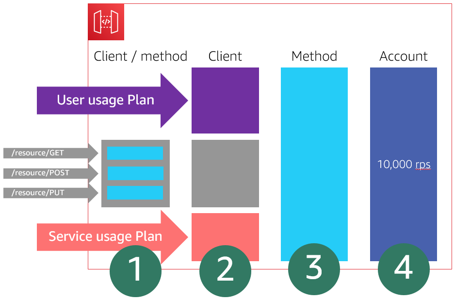
API Gateway limits the steady-state rate and burst requests per second. These are shared across all APIs per Region in an account. For further information on account-level throttling per Region, see the documentation. You can request account-level rate limit increases using the AWS Support Center. For more information, see Amazon API Gateway quotas and important notes.

You can configure your own throttling levels, within the account and Region limits to improve overall performance across all APIs in your account. This restricts the overall request submissions so that they don’t exceed the account-level throttling limits.

You can also configure per-client throttling limits. Usage plans restrict client request submissions to within specified request rates and quotas. These are applied to clients using API keys that are associated with your usage policy as a client identifier. You can add throttling levels per API route, stage, or method that are applied in a specific order.

For more information on API Gateway throttling, see the AWS re:Invent presentation “I didn’t know Amazon API Gateway could do that”.

API Gateway throttling

API Gateway throttling

You can also throttle requests by introducing a buffering layer using Amazon Kinesis Data Stream or Amazon SQS. Kinesis can limit the number of requests at the shard level while SQS can limit at the consumer level. For more information on using SQS as a buffer with Amazon Simple Notification Service (SNS), read “How To: Use SNS and SQS to Distribute and Throttle Events”.

Identify steady-rate and burst rate requests that your workload can sustain at any point in time before performance degraded

Load testing your serverless application allows you to monitor the performance of an application before it is deployed to production. Serverless applications can be simpler to load test, thanks to the automatic scaling built into many of the services. During a load test, you can identify quotas that may act as a limiting factor for the traffic you expect and take action.

Perform load testing for a sustained period of time. Gradually increase the traffic to your API to determine your steady-state rate of requests. Also use a burst strategy with no ramp up to determine the burst rates that your workload can serve without errors or performance degradation. There are a number of AWS Marketplace and AWS Partner Network (APN) solutions available for performance testing, Gatling Frontline, BlazeMeter, and Apica.

In the serverless airline example used in this series, you can run a performance test suite using Gatling, an open source tool.

To deploy the test suite, follow the instructions in the GitHub repository perf-tests directory. Uncomment the deploy.perftest line in the repository Makefile.

Perf-test makefile

Perf-test makefile

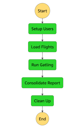
Once the file is pushed to GitHub, AWS Amplify Console rebuilds the application, and deploys an AWS CloudFormation stack. You can run the load tests locally, or use an AWS Step Functions state machine to run the setup and Gatling load test simulation.

Performance test using Step Functions

Performance test using Step Functions

The Gatling simulation script uses constantUsersPerSec and rampUsersPerSec to add users for a number of test scenarios. You can use the test to simulate load on the application. Once the tests run, it generates a downloadable report.

Gatling performance results

Gatling performance results

Artillery Community Edition is another open-source tool for testing serverless APIs. You configure the number of requests per second and overall test duration, and it uses a headless Chromium browser to run its test flows. For Artillery, the maximum number of concurrent tests is constrained by your local computing resources and network. To achieve higher throughput, you can use Serverless Artillery, which runs the Artillery package on Lambda functions. As a result, this tool can scale up to a significantly higher number of tests.

For more information on how to use Artillery, see “Load testing a web application’s serverless backend”. This runs tests against APIs in a demo application. For example, one of the tests fetches 50,000 questions per hour. This calls an API Gateway endpoint and tests whether the AWS Lambda function, which queries an Amazon DynamoDB table, can handle the load.

Artillery performance test

Artillery performance test

This is a synchronous API so the performance directly impacts the user’s experience of the application. This test shows that the median response time is 165 ms with a p95 time of 201 ms.

Performance test API results

Performance test API results

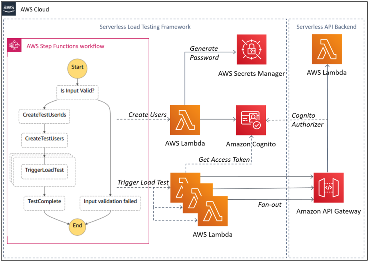
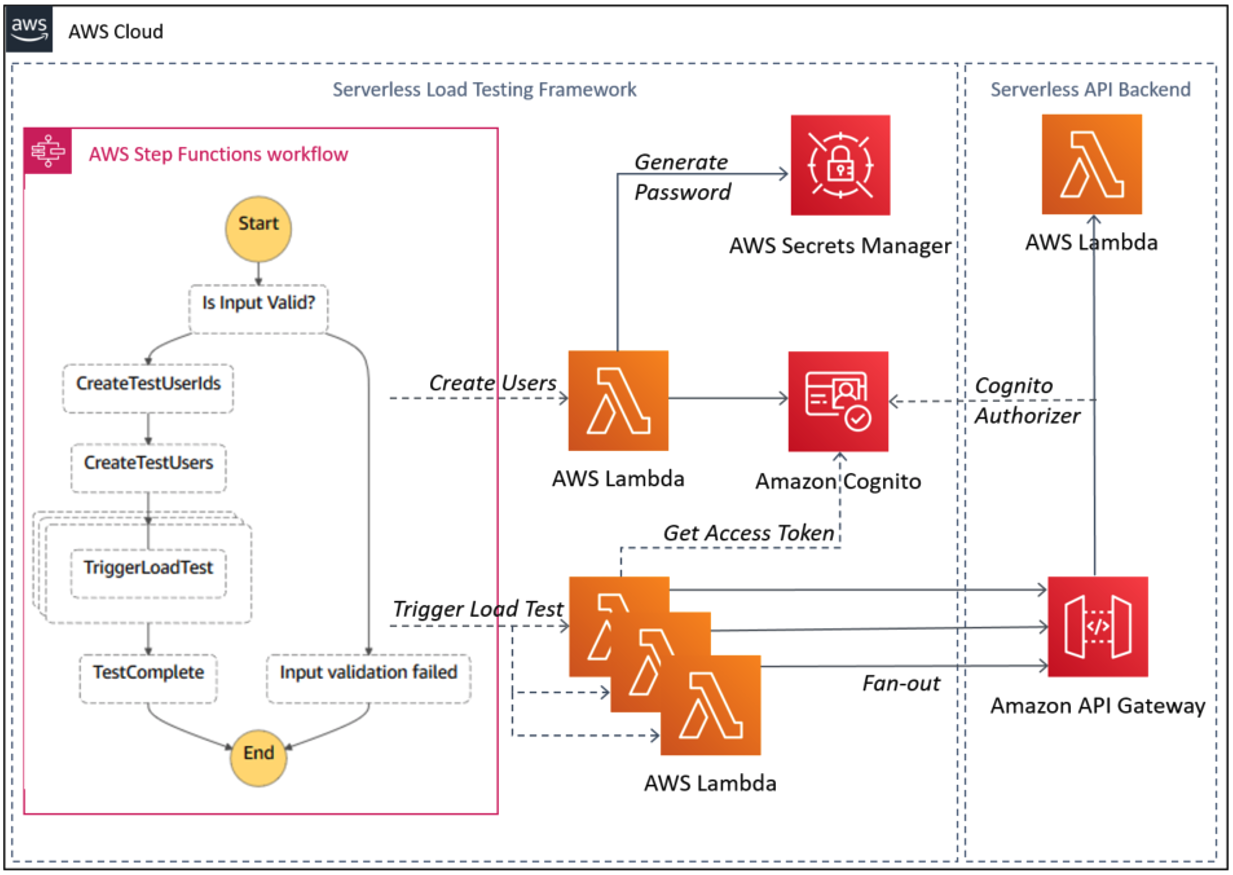
Another consideration for API load testing is whether the authentication and authorization service can handle the load. For more information on load testing Amazon Cognito and API Gateway using Step Functions, see “Using serverless to load test Amazon API Gateway with authorization”.

API load testing with authentication and authorization

API load testing with authentication and authorization

Conclusion

Regulating inbound requests helps you adapt different scaling mechanisms based on customer demand. You can achieve better throughput for your workloads and make them more reliable by controlling requests to a rate that your workload can support.

In this post, I cover controlling inbound request rates using throttling. I show how to use throttling to control steady-rate and burst rate requests. I show some solutions for performance testing to identify the request rates that your workload can sustain before performance degradation.

This well-architected question will be continued where I look at using, analyzing, and enforcing API quotas. I cover mechanisms to protect non-scalable resources.

For more serverless learning resources, visit Serverless Land.

Architecting a Highly Available Serverless, Microservices-Based Ecommerce Site

Post Syndicated from Senthil Kumar original https://aws.amazon.com/blogs/architecture/architecting-a-highly-available-serverless-microservices-based-ecommerce-site/

The number of ecommerce vendors is growing globally—they often handle large traffic at different times of the day and different days of the year. This, in addition to building, managing, and maintaining IT infrastructure on-premises data centers can present challenges to ecommerce businesses’ scalability and growth.

This blog provides you a Serverless on AWS solution that offloads the undifferentiated heavy lifting of managing resources and ensures your businesses’ architecture can handle peak traffic.

Common architecture set up versus serverless solution

The following sections describe a common monolithic architecture and our suggested alternative approach: setting up microservices-based order submission and product search modules. These modules are independently deployable and scalable.

Typical monolithic architecture

Figure 1 shows how a typical on-premises ecommerce infrastructure with different tiers is set up:

  • Web servers serve static assets and proxy requests to application servers
  • Application servers process ecommerce business logic and authentication logic
  • Databases store user and other dynamic data
  • Firewall and load balancers provide network components for load balancing and network security
Monolithic on-premises ecommerce infrastructure with different tiers

Figure 1. Monolithic on-premises ecommerce infrastructure with different tiers

Monolithic architecture tightly couples different layers of the application. This prevents them from being independently deployed and scaled.

Microservices-based modules

Order submission workflow module

This three-layer architecture can be set up in the AWS Cloud using serverless components:

  • Static content layer (Amazon CloudFront and Amazon Simple Storage Service (Amazon S3)). This layer stores static assets on Amazon S3. By using CloudFront in front of the S3 storage cache, you can deliver assets to customers globally with low latency and high transfer speeds.
  • Authentication layer (Amazon Cognito or customer proprietary layer). Ecommerce sites deliver authenticated and unauthenticated content to the user. With Amazon Cognito, you can manage users’ sign-up, sign-in, and access controls, so this authentication layer ensures that only authenticated users have access to secure data.
  • Dynamic content layer (AWS Lambda and Amazon DynamoDB). All business logic required for the ecommerce site is handled by the dynamic content layer. Using Lambda and DynamoDB ensures that these components are scalable and can handle peak traffic.

As shown in Figure 2, the order submission workflow is split into two sections: synchronous and asynchronous.

By splitting the order submission workflow, you allow users to submit their order details and get an orderId. This makes sure that they don’t have to wait for backend processing to complete. This helps unburden your architecture during peak shopping periods when the backend process can get busy.

Microservices-based order submission workflow

Figure 2. Microservices-based order submission workflow

The details of the order, such as credit card information in encrypted form, shipping information, etc., are stored in DynamoDB. This action invokes an asynchronous workflow managed by AWS Step Functions.

Figure 3 shows sample step functions from the asynchronous process. In this scenario, you are using external payment processing and shipping systems. When both systems get busy, step functions can manage long-running transactions and also the required retry logic. It uses a decision-based business workflow, so if a payment transaction fails, the order can be canceled. Or, once payment is successful, the order can proceed.

Amazon Simple Notification Service (Amazon SNS) notifies users whenever their order status changes. You can even extend Step Functions to have it react based on status of shipping.

Sample AWS Step Functions asynchronous workflow that uses external payment processing service and shipping system

Figure 3. Sample AWS Step Functions asynchronous workflow that uses external payment processing service and shipping system

Product search module

Our product search module is set up using the following serverless components:

  • Amazon Elasticsearch Service (Amazon ES) stores product data, which is updated whenever product-related data changes.
  • Lambda formats the data.
  • Amazon API Gateway allows users to search without authentication. As shown in Figure 4, searching for products on the ecommerce portal does not require users to log in. All traffic via API Gateway is unauthenticated.
Microservices-based product search workflow module with dynamic traffic through API Gateway

Figure 4. Microservices-based product search workflow module with dynamic traffic through API Gateway

Replicating data across Regions

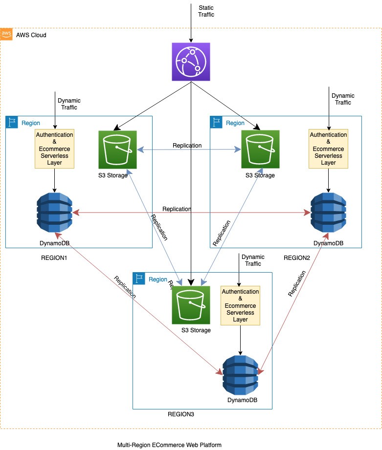
If your ecommerce application runs on multiple Regions, it may require the content and data to be replicated. This allows the application to handle local traffic from that Region and also act as a failover option if the application fails in another Region. The content and data are replicated using the multi-Region replication features of Amazon S3 and DynamoDB global tables.

Figure 5 shows a multi-Region ecommerce site built on AWS with serverless services. It uses the following features to make sure that data between all Regions are in sync for data/assets that do not need data residency compliance:

  • Amazon S3 multi-Region replication keeps static assets in sync for assets.
  • DynamoDB global tables keeps dynamic data in sync across Regions.

Assets that are specific to their Region are stored in Regional specific buckets.

Data replication for a multi-Region ecommerce website built using serverless components

Figure 5. Data replication for a multi-Region ecommerce website built using serverless components

Amazon Route 53 DNS web service manages traffic failover from one Region to another. Route 53 provides different routing policies, and depending on your business requirement, you can choose the failover routing policy.

Best practices

Now that we’ve shown you how to build these applications, make sure you follow these best practices to effectively build, deploy, and monitor the solution stack:

  • Infrastructure as Code (IaC). A well-defined, repeatable infrastructure is important for managing any solution stack. AWS CloudFormation allows you to treat your infrastructure as code and provides a relatively easy way to model a collection of related AWS and third-party resources.
  • AWS Serverless Application Model (AWS SAM). An open-source framework. Use it to build serverless applications on AWS.
  • Deployment automation. AWS CodePipeline is a fully managed continuous delivery service that automates your release pipelines for fast and reliable application and infrastructure updates.
  • AWS CodeStar. Allows you to quickly develop, build, and deploy applications on AWS. It provides a unified user interface, enabling you to manage all of your software development activities in one place.
  • AWS Well-Architected Framework. Provides a mechanism for regularly evaluating your workloads, identifying high risk issues, and recording your improvements.
  • Serverless Applications Lens. Documents how to design, deploy, and architect serverless application workloads.
  • Monitoring. AWS provides many services that help you monitor and understand your applications, including Amazon CloudWatch, AWS CloudTrail, and AWS X-Ray.

Conclusion

In this blog post, we showed you how to architect a highly available, serverless, and microservices-based ecommerce website that operates in multiple Regions.

We also showed you how to replicate data between different Regions for scaling and if your workload fails. These serverless services reduce the burden of building and managing physical IT infrastructure to help you focus more on building solutions.

Related information

Should I Run my Containers on AWS Fargate, AWS Lambda, or Both?

Post Syndicated from Rob Solomon original https://aws.amazon.com/blogs/architecture/should-i-run-my-containers-on-aws-fargate-aws-lambda-or-both/

Containers have transformed how companies build and operate software. Bundling both application code and dependencies into a single container image improves agility and reduces deployment failures. But what compute platform should you choose to be most efficient, and what factors should you consider in this decision?

With the release of container image support for AWS Lambda functions (December 2020), customers now have an additional option for building serverless applications using their existing container-oriented tooling and DevOps best practices. In addition, a single container image can be configured to run on both of these compute platforms: AWS Lambda (using serverless functions) or AWS Fargate (using containers).

Three key factors can influence the decision of what platform you use to deploy your container: startup time, task runtime, and cost. That decision may vary each time a task is initiated, as shown in the three scenarios following.

Design considerations for deploying a container

Total task duration consists of startup time and runtime. The startup time of a containerized task is the time required to provision the container compute resource and deploy the container. Task runtime is the time it takes for the application code to complete.

Startup time: Some tasks must complete quickly. For example, when a user waits for a web response, or when a series of tasks is completed in sequential order. In those situations, the total duration time must be minimal. While the application code may be optimized to run faster, startup time depends on the chosen compute platform as well. AWS Fargate container startup time typically takes from 60 to 90 seconds. AWS Lambda initial cold start can take up to 5 seconds. Following that first startup, the same containerized function has negligible startup time.

Task runtime: The amount of time it takes for a task to complete is influenced by the compute resources allocated (vCPU and memory) and application code. AWS Fargate lets you select vCPU and memory size. With AWS Lambda, you define the amount of allocated memory. Lambda then provisions a proportional quantity of vCPU. In both AWS Fargate and AWS Lambda uses, increasing the amount of compute resources may result in faster completion time. However, this will depend on the application. While the additional compute resources incur greater cost, the total duration may be shorter, so the overall cost may also be lower.

AWS Lambda has a maximum limit of 15 minutes of runtime. Lambda shouldn’t be used for these tasks to avoid the likelihood of timeout errors.

Figure 1 illustrates the proportion of startup time to total duration. The initial steepness of each line shows a rapid decrease in startup overhead. This is followed by a flattening out, showing a diminishing rate of efficiency. Startup time delay becomes less impactful as the total job duration increases. Other factors (such as cost) become more significant.

Figure 1. Ratio of startup time as a function to overall job duration for each service

Figure 1. Ratio of startup time as a function to overall job duration for each service

Cost: When making the choice between Fargate and Lambda, it is important to understand the different pricing models. This way, you can make the appropriate selection for your needs.

Figure 2 shows a cost analysis of Lambda vs Fargate. This is for the entire range of configurations for a runtime task. For most of the range of configurable memory, AWS Lambda is more expensive per second than even the most expensive configuration of Fargate.

Figure 2. Total cost for both AWS Lambda and AWS Fargate based on task duration

Figure 2. Total cost for both AWS Lambda and AWS Fargate based on task duration

From a cost perspective, AWS Fargate is more cost-effective for tasks running for several seconds or longer. If cost is the only factor at play, then Fargate would be the better choice. But the savings gained by using Fargate may be offset by the business value gained from the shorter Lambda function startup time.

Dynamically choose your compute platform

In the following scenarios, we show how a single container image can serve multiple use cases. The decision to run a given containerized application on either AWS Lambda or AWS Fargate can be determined at runtime. This decision depends on whether cost, speed, or duration are the priority.

In Figure 3, an image-processing AWS Batch job runs on a nightly schedule, processing tens of thousands of images to extract location information. When run as a batch job, image processing may take 1–2 hours. The job pulls images stored in Amazon Simple Storage Service (S3) and writes the location metadata to Amazon DynamoDB. In this case, AWS Fargate provides a good combination of compute and cost efficiency. An added benefit is that it also supports tasks that exceed 15 minutes. If a single image is submitted for real-time processing, response time is critical. In that case, the same image-processing code can be run on AWS Lambda, using the same container image. Rather than waiting for the next batch process to run, the image is processed immediately.

Figure 3. One-off invocation of a typically long-running batch job

Figure 3. One-off invocation of a typically long-running batch job

In Figure 4, a SaaS application uses an AWS Lambda function to allow customers to submit complex text search queries for files stored in an Amazon Elastic File System (EFS) volume. The task should return results quickly, which is an ideal condition for AWS Lambda. However, a small percentage of jobs run much longer than the average, exceeding the maximum duration of 15 minutes.

A straightforward approach to avoid job failure is to initiate an Amazon CloudWatch alarm when the Lambda function times out. CloudWatch alarms can automatically retry the job using Fargate. An alternate approach is to capture historical data and use it to create a machine learning model in Amazon SageMaker. When a new job is initiated, the SageMaker model can predict the time it will take the job to complete. Lambda can use that prediction to route the job to either AWS Lambda or AWS Fargate.

Figure 4. Short duration tasks with occasional outliers running longer than 15 minutes

Figure 4. Short duration tasks with occasional outliers running longer than 15 minutes

In Figure 5, a customer runs a containerized legacy application that encompasses many different kinds of functions, all related to a recurring data processing workflow. Each function performs a task of varying complexity and duration. These can range from processing data files, updating a database, or submitting machine learning jobs.

Using a container image, one code base can be configured to contain all of the individual functions. Longer running functions, such as data preparation and big data analytics, are routed to Fargate. Shorter duration functions like simple queries can be configured to run using the container image in AWS Lambda. By using AWS Step Functions as an orchestrator, the process can be automated. In this way, a monolithic application can be broken up into a set of “Units of Work” that operate independently.

Figure 5. Heterogeneous function orchestration

Figure 5. Heterogeneous function orchestration

Conclusion

If your job lasts milliseconds and requires a fast response to provide a good customer experience, use AWS Lambda. If your function is not time-sensitive and runs on the scale of minutes, use AWS Fargate. For tasks that have a total duration of under 15 minutes, customers must decide based on impacts to both business and cost. Select the service that is the most effective serverless compute environment to meet your requirements. The choice can be made manually when a job is scheduled or by using retry logic to switch to the other compute platform if the first option fails. The decision can also be based on a machine learning model trained on historical data.

Using serverless to load test Amazon API Gateway with authorization

Post Syndicated from Eric Johnson original https://aws.amazon.com/blogs/compute/using-serverless-to-load-test-amazon-api-gateway-with-authorization/

This post was written by Ashish Mehra, Sr. Solutions Architect and Ramesh Chidirala, Solutions Architect

Many customers design their applications to use Amazon API Gateway as the front door and load test their API endpoints before deploying to production. Customers want to simulate the actual usage scenario, including authentication and authorization. The load test ensures that the application works as expected under high traffic and spiky load patterns.

This post demonstrates using AWS Step Functions for orchestration, AWS Lambda to simulate the load and Amazon Cognito for authentication and authorization. There is no need to use any third-party software or containers to implement this solution.

The serverless load test solution shown here can scale from 1,000 to 1,000,000 calls in a few minutes. It invokes API Gateway endpoints but you can reuse the solution for other custom API endpoints.

Overall architecture

Overall architecture diagram

Overall architecture diagram

Solution design 

The serverless API load test framework is built using Step Functions that invoke Lambda functions using a fan-out design pattern. The Lambda function obtains the user specific JWT access token from Amazon Cognito user pool and invokes the API Gateway authenticated route..

The solution contains two workflows.

1. Load test workflow

The load test workflow comprises a multi-step process that includes a combination of sequential and parallel steps. The sequential steps include user pool configuration, user creation, and access token generation followed by API invocation in a fan-out design pattern. Step Functions provides a reliable way to build and run such multi-step workflows with support for logging, retries, and dynamic parallelism.

Step Functions workflow diagram for load test

Step Functions workflow diagram for load test

The Step Functions state machine orchestrates the following workflow:

  1. Validate input parameters.
  2. Invoke Lambda function to create a user ID array in the series loadtestuser0, loadtestuser1, and so on. This array is passed as an input to subsequent Lambda functions.
  3. Invoke Lambda to create:
    1. Amazon Cognito user pool
    2. Test users
    3. App client configured for admin authentication flow.
  4. Invoke Lambda functions in a fan-out pattern using dynamic parallelism support in Step Functions. Each function does the following:
    1. Retrieves an access token (one token per user) from Amazon Cognito
    2. Sends an HTTPS request to the specified API Gateway endpoint by passing an access token in the header.

For testing purposes, users can configure mock integration or use Lambda integration for the backend.

2. Cleanup workflow

Step Functions workflow diagram for cleanup

Step Functions workflow diagram for cleanup

As part of the cleanup workflow, the Step Functions state machine invokes a Lambda function to delete the specified number of users from the Amazon Cognito user pool.

Prerequisites to implement the solution

The following prerequisites are required for this walk-through:

  1. AWS account
  2. AWS SAM CLI
  3. Python 3.7
  4. Pre-existing non-production API Gateway HTTP API deployed with a JWT authorizer that uses Amazon Cognito as an identity provider. Refer to this video from the Twitch series #SessionsWithSAM which provides a walkthough for building and deploying a simple HTTP API with JWT authorizer.

Since this solution involves modifying API Gateway endpoint’s authorizer settings, it is recommended to load test non-production environments or production comparable APIs. Revert these settings after the load test is complete. Also, first check Lambda and Amazon Cognito Service Quotas in the AWS account you plan to use.

Step-by-step instructions

Use the AWS CloudShell to deploy the AWS Serverless Application Model (AWS SAM) template. AWS CloudShell is a browser-based shell pre-installed with common development tools. It includes 1 GB of free persistent storage per Region pre-authenticated with your console credentials. You can also use AWS Cloud9 or your preferred IDE. You can check for AWS CloudShell supported Regions here. Depending on your load test requirements, you can specify the total number of unique users to be created. You can also specify the number of API Gateway requests to be invoked per user every time you run the load test. These factors influence the overall test duration, concurrency and cost. Refer to the cost optimization section of this post for tips on minimizing the overall cost of the solution. Refer to the cleanup section of this post for instructions to delete the resources to stop incurring any further charges.

  1. Clone the repository by running the following command:
    git clone https://github.com/aws-snippets/sam-apiloadtest.git
  2. Change to the sam-apiloadtest directory and run the following command to build the application source:
    sam build
  3. Run the following command to package and deploy the application to AWS, with a series of prompts. When prompted for apiGatewayUrl, provide the API Gateway URL route you intend to load test.
    sam deploy --guided

    Example of SAM deploy

    Example of SAM deploy

  4. After the stack creation is complete, you should see UserPoolID and AppClientID in the outputs section.

    Example of stack outputs

    Example of stack outputs

  5. Navigate to the API Gateway console and choose the HTTP API you intend to load test.
  6. Choose Authorization and select the authenticated route configured with a JWT authorizer.

    API Gateway console display after stack is deployed

    API Gateway console display after stack is deployed

  7. Choose Edit Authorizer and update the IssuerURL with Amazon Cognito user pool ID and audience app client ID with the corresponding values from the stack output section in step 4.

    Editing the issuer URL

    Editing the issuer URL

  8. Set authorization scope to aws.cognito.signin.user.admin.

    Setting the authorization scopes

    Setting the authorization scopes

  9. Open the Step Functions console and choose the state machine named apiloadtestCreateUsersAndFanOut-xxx.
  10. Choose Start Execution and provide the following JSON input. Configure the number of users for the load test and the number of calls per user:
    {
      "users": {
        "NumberOfUsers": "100",
        "NumberOfCallsPerUser": "100"
      }
    }
  11. After the execution, you see the status updated to Succeeded.


Checking the load test results

The load test’s primary goal is to achieve high concurrency. The main metric to check the test’s effectiveness is the count of successful API Gateway invocations. While load testing your application, find other metrics that may identify potential bottlenecks. Refer to the following steps to inspect CloudWatch Logs after the test is complete:

  1. Navigate to API Gateway service within the console, choose Monitor → Logging, select the $default stage, and choose the Select button.
  2. Choose View Logs in CloudWatch to navigate to the CloudWatch Logs service, which loads the log group and displays the most recent log streams.
  3. Choose the “View in Logs Insights” button to navigate to the Log Insights page. Choose Run Query.
  4. The query results appear along with a bar graph showing the log group’s distribution of log events. The number of records indicates the number of API Gateway invocations.

    Histogram of API Gateway invocations

    Histogram of API Gateway invocations

  5. To visualize p95 metrics, navigate to CloudWatch metrics, choose ApiGateway → ApiId → Latency.
  6. Choose the “Graphed metrics (1)” tab.

    Addig latency metric

    Addig latency metric

  7. Select p95 from the Statistic dropdown.

    Setting the p95 value

    Setting the p95 value

  8. The percentile metrics help visualize the distribution of latency metrics. It can help you find critical outliers or unusual behaviors, and discover potential bottlenecks in your application’s backend.

    Example of the p95 data

    Example of the p95 data

Cleanup 

  1. To delete Amazon Cognito users, run the Step Functions workflow apiloadtestDeleteTestUsers. Provide the following input JSON with the same number of users that you created earlier:
    {
    “NumberOfUsers”: “100”
    }
  2. Step Functions invokes the cleanUpTestUsers Lambda function. It is configured with the test Amazon Cognito user pool ID and app client ID environment variables created during the stack deployment. The users are deleted from the test user pool.
  3. The Lambda function also schedules the corresponding KMS keys for deletion after seven days, the minimum waiting period.
  4. After the state machine is finished, navigate to Cognito → Manage User Pools → apiloadtest-loadtestidp → Users and Groups. Refresh the page to confirm that all users are deleted.
  5. To delete all the resources permanently and stop incurring cost, navigate to the CloudFormation console, select aws-apiloadtest-framework stack, and choose Delete → Delete stack.

Cost optimization

The load test workflow is repeatable and can be reused multiple times for the same or different API Gateway routes. You can reuse Amazon Cognito users for multiple tests since Amazon Cognito pricing is based on the monthly active users (MAUs). Repeatedly deleting and recreating users may exceed the AWS Free Tier or incur additional charges.

Customizations

You can change the number of users and number of calls per user to adjust the API Gateway load. The apiloadtestCreateUsersAndFanOut state machine validation step allows a maximum value of 1,000 for input parameters NumberOfUsers and NumberOfCallsPerUser.

You can customize and increase these values within the Step Functions input validation logic based on your account limits. To load test a different API Gateway route, configure the authorizer as per the step-by-step instructions provided earlier. Next, modify the api_url environment variable within aws-apiloadtest-framework-triggerLoadTestPerUser Lambda function. You can then run the load test using the apiloadtestCreateUsersAndFanOut state machine.

Conclusion

The blog post shows how to use Step Functions and its features to orchestrate a multi-step load test solution. I show how changing input parameters could increase the number of calls made to the API Gateway endpoint without worrying about scalability. I also demonstrate how to achieve cost optimization and perform clean-up to avoid any additional charges. You can modify this example to load test different API endpoints, identify bottlenecks, and check if your application is production-ready.

For more serverless learning resources, visit Serverless Land.

Field Notes: Orchestrating and Monitoring Complex, Long-running Workflows Using AWS Step Functions

Post Syndicated from Max Winter original https://aws.amazon.com/blogs/architecture/field-notes-orchestrating-and-monitoring-complex-long-running-workflows-using-aws-step-functions/

Situation:

IHS Markit’s Wall Street Office (WSO) offers financial reports to hundreds of clients worldwide. When IHS Markit completed the migration of WSO’s SaaS software to AWS, it unlocked the power and agility to deliver new product features monthly, as opposed to a multi-year release cycle. This migration also presented a great opportunity to further enhance the customer experience by automating the WSO reporting team’s own Continuous Integration and Continuous Deployment (CI/CD) workflow. WSO then offered the same migration workflow to its on-prem clients, who needed the ability to upgrade quickly in order to meet a regulatory LIBOR reporting deadline. This rapid upgrade was enabled by fully automating regression testing of new software versions.

In this blog post, I outline the architectures created in collaboration with WSO to orchestrate and monitor the complex, long-running reconciliation workflows in their environment by leveraging the power of AWS Step Functions. To enable each client’s migration to AWS, WSO needed to ensure that the new, AWS version of the reporting application produced identical outputs to the previous, on-premises version. For a single migration, the process is as follows:

  • spin up the old version of the SQL Server and reporting engine on Windows servers,
  • run reports,
  • repeat the process with the new version,
  • compare the outputs and review the differences.

The problem came with scaling this process.  IHS Markit provides financial solutions and tools to numerous clients. To enable these clients to transition away from LIBOR, the WSO team was tasked with migrating over 80 instances of the application, and reconciling hundreds of reports for each migration. During upgrades, customers must manually validate custom extracts created in the WSO Reporting application against current and next version, which limits upgrade frequency and increases the resourcing cost of these validations. Without automation, upgrading all clients would have taken an entire new Operations team, and cost the firm over 700 developer-hours to meet the regulatory LIBOR cessation deadline.

WSO was able to save over 4,000 developer-hours by making this process repeatable so it can be used as an automated regression test as part of the regular Systems Development Lifecycle process  The following diagram shows the reconciliation workflow steps enabled as part of this automated process.

Reconciliation Workflow Steps

Figure 1 – Reconciliation Workflow Steps

Complication:

The team quickly realized that a Serverless and event-driven solution would be required to make this process manageable. The initial approach was to use AWS Lambda functions to call PowerShell scripts to perform each step in the reconciliation process. They also used Amazon SNS to invoke the next Lambda function when the previous step completed.

The problem came when the Operations team tried to monitor these Lambda functions, with multiple parallel reconciliations running concurrently. The Lambda outputs became mixed together in shared Amazon Cloud Watch log groups, and there was no way to quickly see the overall progress of any given reconciliation workflow. It was also difficult to figure out how to recover from errors.

Furthermore, the team found that some steps in this process, such as database restoration, ran longer than the 15 minute Lambda timeout limit. As a result, they were forced to look for alternatives to manage these long-running steps. Following is an architecture diagram showing the serverless component used to automate and scale the process.

Initial Orchestration Architecture

Figure 2 – Initial Orchestration Architecture

Solution:

Enter Step Functions and AWS Systems Manager (formerly known as SSM) Automation. To address the problem of orchestrating the many sequential and parallel steps in our workflow, AWS Solutions Architects suggested replacing Amazon SNS with AWS Step Functions.

The Step Functions state machine controls the order in which the steps are invoked, including successful and error state transitions. The service is integrated with 14 other AWS services (Lambda function, SSM Automation, Amazon ECS, and more.), and can invoke them, as well as manual actions. These calls can be synchronous or run via steps that wait for an event. A state machine instance is long-lived and can support processes that take up to a year to complete.

Step Function Designer UI

Figure 3 – Step Function Designer UI

This immediately gave the Development team a holistic, visual way to design our workflow, and offered Operations a graphical user interface (UI) to monitor ongoing reconciliations in real time. The Step Functions console lists out all running and past reconciliations, including their status, and allows the operator to drill down into the detailed state diagram of any given reconciliation. The operator can then see how far it’s progressed or where it encountered an error.

The UI also provides Amazon CloudWatch links for any given step, isolating the logs of that particular Lambda execution, eliminating the need to search through the CloudWatch log group manually. The screenshot below illustrates what an in-progress Step Function looks to an operator, with each step listed out with its own status and a link to its log.

Step Function Execution Monitor

Figure 4 – Step Function Execution Monitor


Figure 5 - Step Function Execution Detail Viewer

Figure 5 – Step Function Execution Detail Viewer


Figure 6 -Step Function Log Group in CloudWatch

Figure 6 -Step Function Log Group in Amazon CloudWatch

The team also used the Step Function state machine as a container for metadata about each particular reconciliation process instance (like the environment ID and the database and Amazon EC2 instances associated with that environment), reducing the need to pass this data between Lambda functions.

To solve the problem of long-running PowerShell scripts, AWS Solutions Architects suggested using SSM Automation. Unlike Lambda functions, SSM Automation is meant to run operational scripts, with no maximum time limit. They also have native PowerShell integration, which you can use to call the existing scripts and capture their output.


SSM Automation UI for Monitoring Long-running Tasks and Manual Approval Steps

Figure 7 – SSM Automation UI for Monitoring Long-running Tasks and Manual Approval Steps

To save time running hundreds of reports, the team looked into the ‘Map State’ feature of Step Functions. Map takes an array of input data, then creates an instance of the step (in this case a Lambda call) for each item in this array.  It waits for them all to complete before proceeding.

This is recommended to implement as a fan-out pattern with almost no orchestration code. The Map State step also gives Operations users the option to limit the level of parallelism, in this case letting only 5 reports run simultaneously. This prevents overloading our reporting applications and databases.

Figure 8 – Map State is used to Fan Out the “CompareReport” Step as Multiple Parallel Steps

To deal with errors in any of the workflow steps, the Development team introduced a manual review step, which you can model in Step Functions. The manual step notifies a mailing list of the error, then waits for a reply to tell it whether to retry or abort the workflow.

The only challenge the Development team found was the mechanism for re-running an individual failed step. At this time, any failure needs to have an explicit state transition within the Step Function’s state diagram. While the Step Function can auto-retry a step, the team wanted to insert a wait-for-human-investigation step before retrying the more expensive and complex steps.

This presented 2 options:

  1. add wait-and-loop-back steps around every step we may want to retry,
  2. route all failures to a single wait-for-investigation step.

The former added significant complexity to the state machine, so AWS Solutions Architects raised this as a product feature that should be added to the Step Functions UI.

The proposed enhancement would allow any failed step to be manually rerun or skipped via UI controls, without adding explicit steps to each state machine to model this. In the meantime, the Dev team went with the latter approach, and had the human error review step loop back to the top of the state machine to retry the entire workflow. To avoid re-running long steps, they created a check within the step Lambda function to query the Step Functions API and determine whether that step had already succeeded before the loop-back, and complete it instantly if it had.


Human Intervention Steps Used to Allow Time to Review Results or Resolve Errors Before Retrying Failed Steps

Figure 9 – Human Intervention Steps Used to Allow Time to Review Results or Resolve Errors Before Retrying Failed Steps

Conclusion:

Within 6 weeks, WSO was able to run the first reconciliations and begin the LIBOR migration on time. The Step Function Designer instantly gave the Developer team an operator UI and workflow orchestration engine. Normally, this would have required the creation of an entire 3-tier stack, scheduler and logging infrastructure.

Instead, using Step Functions allowed the developers to spend their time on the reconciliation logic that makes their application unique. The report compare tool developed by the WSO team provides clients with automated artifacts confirming that customer report data remained identical between current version and next version of WSO. The new testing artifacts provide clients with robust and comprehensive testing of critical data extracts.

The Completed Step Function which Orchestrates an Entire Reconciliation Process

Figure 10 -The Completed Step Function which Orchestrates an Entire Reconciliation Process


We hope that this blog post provided useful insights to help determine if using AWS Step Functions are a good fit for you.

Field Notes provides hands-on technical guidance from AWS Solutions Architects, consultants, and technical account managers, based on their experiences in the field solving real-world business problems for customers.


ICYMI: Serverless Q2 2021

Post Syndicated from James Beswick original https://aws.amazon.com/blogs/compute/icymi-serverless-q2-2021/

Welcome to the 14th edition of the AWS Serverless ICYMI (in case you missed it) quarterly recap. Every quarter, we share all of the most recent product launches, feature enhancements, blog posts, webinars, Twitch live streams, and other interesting things that you might have missed!

Q2 calendar

In case you missed our last ICYMI, check out what happened last quarter here.

AWS Step Functions

Step Functions launched Workflow Studio, a new visual tool that provides a drag-and-drop user interface to build Step Functions workflows. This exposes all the capabilities of Step Functions that are available in Amazon States Language (ASL). This makes it easier to build and change workflows and build definitions in near-real time.

For more:

Workflow Studio

The new data flow simulator in the Step Functions console helps you evaluate the inputs and outputs passed through your state machine. It allows you to simulate each of the fields used to process data and updates in real time. It can help accelerate development with workflows and help visualize JSONPath processing.

For more:

Data flow simulator

Also, Amazon API Gateway can now invoke synchronous Express Workflows using REST APIs.

Amazon EventBridge

EventBridge now supports cross-Region event routing from any commercial AWS Region to a list of supported Regions. This feature allows you to centralize global events for auditing and monitoring or replicate events across Regions.

EventBridge cross-Region routing

The service now also supports bus-to-bus event routing in the same Region and in the same AWS account. This can be useful for centralizing events related to a single project, application, or team within your organization.

EventBridge bus-to-bus

You can now use EventBridge as a resource within Step Functions workflows. This provides a direct service integration for both standard and Express Workflows. You can publish events directly to a specified event bus using either a request-response or wait-for-callback pattern.

EventBridge added a new target for rules – Amazon SageMaker Pipelines. This allows you to use a rule to trigger a continuous integration and continuous deployment (CI/CD) service for your machine learning workloads.

AWS Lambda

Lambda Extensions

AWS Lambda extensions are now generally available including some performance and functionality improvements. Lambda extensions provide a new way to integrate your chosen monitoring, observability, security, and governance tools with AWS Lambda. These use the Lambda Runtime Extensions API to integrate with the execution environment and provide hooks into the Lambda lifecycle.

To help build your own extensions, there is an updated GitHub repository with example code.

To learn more:

  • Watch a Tech Talk with Julian Wood.
  • Watch the 8-episode Learning Path series covering all aspects of extensions.

Extensions available today

Amazon CloudWatch Lambda Insights support for Lambda container images is now generally available.

Amazon SNS

Amazon SNS has expanded the set of filter operators available to include IP address matching, existence of an attribute key, and “anything-but” matching.

The service has also introduced an SMS sandbox to help developers testing workloads that send text messages.

To learn more:

Amazon DynamoDB

DynamoDB announced CloudFormation support for several features. First, it now supports configuring Kinesis Data Streams using CloudFormation. This allows you to use infrastructure as code to set up Kinesis Data Streams instead of DynamoDB streams.

The service also announced that NoSQL Workbench now supports CloudFormation, so you can build data models and configure table capacity settings directly from the tool. Finally, you can now create and manage global tables with CloudFormation.

Learn how to use the recently launched Serverless Patterns Collection to configure DynamoDB as an event source for Lambda.

AWS Amplify

Amplify Hosting announced support for server-side rendered (SSR) apps built with the Next.js framework. This provides a zero configuration option for developers to deploy and host their Next.js-based applications.

The Amplify GLI now allows developers to make multiple DynamoDB GSI updates in a single deployment. This can help accelerate data model iterations. Additionally, the data management experience in the Amplify Admin UI launched at AWS re:Invent 2020 is now generally available.

AWS Serverless Application Model (AWS SAM)

AWS SAM has a public preview of support for local development and testing of AWS Cloud Development Kit (AWS CDK) projects.

To learn more:

Serverless blog posts

Operating Lambda

The “Operating Lambda” blog series includes the following posts in this quarter:

Streaming data

The “Building serverless applications with streaming data” blog series shows how to use Lambda with Kinesis.

Getting started with serverless for developers

Learn how to build serverless applications from your local integrated development environment (IDE).

April

May

June

Tech Talks & Events

We hold AWS Online Tech Talks covering serverless topics throughout the year. These are listed in the Serverless section of the AWS Online Tech Talks page. We also regularly deliver talks at conferences and events around the world, speak on podcasts, and record videos you can find to learn in bite-sized chunks.

Here are some from Q2:

Serverless Live was a day of talks held on May 19, featuring the serverless developer advocacy team, along with Adrian Cockroft and Jeff Barr. You can watch a replay of all the talks on the AWS Twitch channel.

Videos

YouTube ServerlessLand channel

Serverless Office Hours – Tues 10 AM PT / 1PM EST

Weekly live virtual office hours. In each session we talk about a specific topic or technology related to serverless and open it up to helping you with your real serverless challenges and issues. Ask us anything you want about serverless technologies and applications.

YouTube: youtube.com/serverlessland
Twitch: twitch.tv/aws

April

May

June

DynamoDB Office Hours

Are you an Amazon DynamoDB customer with a technical question you need answered? If so, join us for weekly Office Hours on the AWS Twitch channel led by Rick Houlihan, AWS principal technologist and Amazon DynamoDB expert. See upcoming and previous shows

Learning Path – AWS Lambda Extensions: The deep dive

Are you looking for a way to more easily integrate AWS Lambda with your favorite monitoring, observability, security, governance, and other tools? Welcome to AWS Lambda extensions: The deep dive, a learning path video series that shows you everything about augmenting Lambda functions using Lambda extensions.

There are also other helpful videos covering serverless available on the Serverless Land YouTube channel.

Still looking for more?

The Serverless landing page has more information. The Lambda resources page contains case studies, webinars, whitepapers, customer stories, reference architectures, and even more Getting Started tutorials.

You can also follow the Serverless Developer Advocacy team on Twitter to see the latest news, follow conversations, and interact with the team.

Prototyping at speed with AWS Step Functions new Workflow Studio

Post Syndicated from Benjamin Smith original https://aws.amazon.com/blogs/compute/prototyping-at-speed-with-aws-step-functions-new-workflow-studio/

AWS recently introduced Workflow Studio for AWS Step Functions. This is a new visual builder for creating Step Functions workflows in the AWS Management Console. This post shows how to use the Workflow Studio for rapid workflow prototyping. It also explains how to transition to local development, integrating the prototype with your infrastructure as code templates.

Since its release in December 2016, developers have been building Step Functions workflows with Amazon States Language (ASL) to orchestrate multiple services into business-critical applications. Developers wanted faster ways to prototype and build orchestration workflows without writing custom code or using additional services.

­­­­­­

What’s new?

The new Step Functions Workflow Studio provides an additional workflow building experience. Developers and business users can now build prototype workflows quickly with a graphical user interface in the Step Functions console.

These workflo­­­ws can include all the same workflow states, patterns, and service integrations available when building with ASL. Each state is configured using editable forms. The workflow ASL definition can be exported for further editing in the console or in your local integrated development environment (IDE). Workflow Studio can build new workflows or edit a pre-existing workflow. To get started with Workflow Studio, see this introduction video.

Business users

Workflow Studio provides new opportunities for a more diverse range of users to build step functions workflows. Business users and those in non-technical roles can quickly create workflow prototypes. This can help to reason about and understand business processes before passing to a developer to add business logic and configure service integrations.

Rapid workflow prototyping

Workflow Studio allows you to create placeholders for AWS Lambda functions and other service integrations using the ‘drag-and-drop’ interface. This means that resources do not need to exist before designing the workflow. Once a workflow is prototyped you can save and continue to edit in the console or copy the ASL definition to your local IDE. You can then incorporate the workflow with application resources and infrastructure as code templates.

In the following steps, I use Workflow Studio to build the workflow described in this post. The full application template is found in this GitHub repository. The workflow analyzes web form submissions for negative sentiment. It generates a case reference number and saves the data in an Amazon DynamoDB table. The workflow returns the case reference number and message sentiment score.

To start fast prototyping for this workflow with the visual studio:

  1. Log into the Step Functions console and choose Create state machine.
  2. Choose Design your workflow visually from the authoring method section. This opens up Workflow Studio.
  3. Choose AWS Lambda Invoke from the Actions menu and drag it into the workflow.
  4. Choose the Configuration tab from the Form panel and enter the name Detect Sentiment in the State name field.
  5. In the function name field, choose Enter Function Name.
  6. Enter ${DetectSentiment} into the function name parameters field. This is a dynamic reference to a value that is provided by an Infrastructure-as-code template.

    The Workflow Studio provides an interface to add input and output path processing configurations to the workflow.
  7. Choose the Output tab and select Combine input and result with ResultPath. Selecting this option uses the ResultPath filter to add the result into the original state input. The specified path indicates where to add the result.
  8. Enter $.SentimentResults into the path ResultsPath text input.
  9. View the workflow ASL definition by choosing Definition from the top menu. This shows:
    1. The state is named Detect Sentiment.
    2. The Lambda function name uses a dynamic reference to ${DetectSentiment}. This is provided by the infrastructure-as-code template, explained in the following steps.
    3. A default retry configuration is defined.
    4. The ResultPath is configured.

Continue building the workflow this way, adding more Task and Flow states. A completed workflow looks as follows:

Transitioning to local development

Once the workflow is created in the Workflow Studio, you can export the ASL definition to a local IDE to incorporate into an infrastructure as code template. The template describes all the AWS resources that make up the application:

  1. To copy the ASL definition, choose the Definition button in the top navigation, and copy the entire ASL workflow definition to the clipboard.
  2. Create a new directory in your local filesystem named statemachine and save the definition to a file in this directory named sfn-template.asl.json. The following screenshot shows how the workflow appears in your IDE when rendered with the AWS Toolkit for Visual Studio Code.

  3. AWS Serverless Application Model (AWS SAM) is an open-source infrastructure as code framework for building serverless applications.
  4. Create an AWS SAM template named template.yaml to describe the application resources. A completed version of this file is found in this GitHub repository.
  5. Create a directory for each Lambda function. Within each directory, save the function code to a file called app.js. The function code, can be found in this GitHub repository. The final application file directory looks as follows:
    root
    ┣ LambdaFunctions/
    ┃ ┣ GenerateReferenceNumber/
    ┃ ┃ ┗ app.js
    ┃ ┣ detectSentiment/
    ┃ ┃ ┗ app.js
    ┃ ┗ sendEmailConfirmation/
    ┃   ┗ app.js
    ┣ statemachine/
    ┃ ┗ sfn-template.asl.json
    ┗ template.yaml

The full application can be found in this GitHub repository.

The AWS SAM template describes the Step Functions workflow’s security permissions and allows for dynamic referencing of the resources described within the template such as the Lambda functions and DynamoDB table:

##########################################################################
#   STEP FUNCTION                                                        #
##########################################################################

  ProcessFormStateMachineExpressSync:
    Type: AWS::Serverless::StateMachine # More info about State Machine Resource: https://docs.aws.amazon.com/serverless-application-model/latest/developerguide/sam-resource-statemachine.html
    Properties:
      DefinitionUri: statemachine/sfn-template.asl.json
      DefinitionSubstitutions:
        NotifyAdminWithSES: !Ref NotifyAdminWithSES
        GenerateRefernceNumber: !Ref GenerateRefernceNumber
        DetectSentiment: !Ref DetectSentiment
        DDBTable: !Ref FormDataTable
      Policies: # Find out more about SAM policy templates: https://docs.aws.amazon.com/serverless-application-model/latest/developerguide/serverless-policy-templates.html
        - LambdaInvokePolicy:
            FunctionName: !Ref NotifyAdminWithSES
        - LambdaInvokePolicy:
            FunctionName: !Ref DetectSentiment
        - LambdaInvokePolicy:
            FunctionName: !Ref GenerateRefernceNumber
        - DynamoDBWritePolicy:
            TableName: !Ref FormDataTable
      Type: EXPRESS
  • The DefinitionURI value provides the location of the ASL definition that is exported from the Workflow Studio, in statemachine/sfn-template.asl.json.
  • The DefinitionSubstitutions values provide the names of the resources used within the workflow. Here you see $.DetectSentiment Lambda function name passed to the workflow definition. This was entered into the Workflow Studio in the previous steps.

The application is deployed using the AWS SAM CLI. Follow these steps in the GitHub repository to deploy the application.

Once the application is deployed, the workflow can be edited by updating the ASL definition in the Step Functions console or the local template file. It can also be edited from the drag-and-snap interface in the Workflow Studio. Any edits made in the AWS Management Console should be copied back to the local template file.

Conclusion

The AWS Step Functions Workflow Studio is a new visual builder for creating Step Functions workflows in the AWS Management Console. The drag-and-drop interface can be used to build new or edit existing workflows quickly. Each state is configured using editable forms, with the ASL definition visible and available for export as you build.

This post shows how to use the Workflow Studio for rapid workflow prototyping. It explains how to export the ASL definition to your local IDE and integrate it with your infrastructure as code application templates.

The Workflow Studio is included in Step Functions pricing at no additional fee and is available in all regions where Step Functions is available. To get started, visit https://aws.amazon.com/stepfunctions.

New – AWS Step Functions Workflow Studio – A Low-Code Visual Tool for Building State Machines

Post Syndicated from Marcia Villalba original https://aws.amazon.com/blogs/aws/new-aws-step-functions-workflow-studio-a-low-code-visual-tool-for-building-state-machines/

AWS Step Functions allow you to build scalable, distributed applications using state machines. Until today, building workflows on Step Functions required you to learn and understand Amazon State Language (ASL). Today, we are launching Workflow Studio, a low-code visual tool that helps you learn Step Functions through a guided interactive interface and allows you to prototype and build workflows faster.

In December 2016, when Step Functions was launched, I was in the middle of a migration to serverless. My team moved all the business logic from applications that were built for a traditional environment to a serverless architecture. Although we tried to have functions that did one thing and one thing only, when we put all the state management from our applications into the functions, they became very complex. When I saw that Step Functions was launched, I realized they would reduce the complexity of the serverless application we were building. The downside was that I spent a lot of time learning and writing state machines using ASL, learning how to invoke different AWS services, and performing the flow operations the state machine required. It took weeks of work and lots of testing to get it right.

Step Functions is amazing for visualizing the processes inside your distributed applications, but developing those state machines is not a visual process. Workflow Studio makes it easy for developers to build serverless workflows. It empowers developers to focus on their high-value business logic while reducing the time spent writing configuration code for workflow definitions and building data transformations.

Workflow Studio is great for developers who are new to Step Functions, because it reduces the time to build their first workflow and provides an accelerated learning path where developers learn by doing. Workflow Studio is also useful for developers who are experienced in building workflows, because they can now develop them faster using a visual tool. For example, you can use Workflow Studio to do prototypes of the workflows and share them with your stakeholders quickly. Or you can use Workflow Studio to design the boilerplate of your state machine. When you use Workflow Studio, you don’t need to have all the resources deployed in your AWS account. You can build the state machines and start completing them with the different actions as they get ready.

Workflow Studio simplifies the building of enterprise applications such as ecommerce platforms, financial transaction processing systems, or e-health services. It abstracts away the complexities of building fault-tolerant, scalable applications by assembling AWS services into workflows. Because Workflow Studio exposes many of the capabilities of AWS services in a visual workflow, it’s easy to sequence and configure calls to AWS services and APIs and transform the data flowing through a workflow.

Build a workflow using Workflow Studio
Imagine that you need to build a system that validates data when an account is created. If the input data is correct, the system saves the record in persistent storage and an email is sent to the administrator to confirm the account was created successfully. If the account cannot be created due to a validation error, the data is not stored and an email is sent to notify the administrator that there was a problem with the creation of the account.

There are many ways to solve this problem, but if you want to make the application with the least amount of code, and take advantage of all the managed services that AWS provides, you should use Workflow Studio to design the state machine and build the integrations with all the managed services.

Architectural diagram of what we are building

Let me show you how easy is to create a state machine using Workflow Studio. To get started, go to the Step Functions console and create a state machine. You will see an option to start designing the new state machine visually with Workflow Studio.

Creating a new state machine

You can start creating state machines in Workflow Studio. In the left pane, the States Browser, you can view and search the available actions and flow states. Actions are operations you can perform using AWS services, like invoking an AWS Lambda function, making a request with Amazon API Gateway, and sending a message to an Amazon Simple Notification Service (SNS) topic. Flows are the state types you can use to make a workflow appropriate for your use case.

Here are some of the available flow states:

  • Choice: Adds if-then-else logic.
  • Parallel: Adds parallel branches.
  • Map: Adds a for-each loop.
  • Wait: Delays for a specific time.

In the center of the page, you can see the state machine you are currently working on.

Screenshot of Studio workflow first view

To build the account validator workflow, you need:

  • One task that invokes a Lambda function that validates the data provided to create the account.
  • One task that puts an item into a DynamoDB table.
  • Two tasks that put a message to an SNS topic.
  • One choice flow state, to decide which action to take, depending on the results of a Lambda function.

When creating the workflow, you don’t need to have all the AWS resources in advance to start working on the state machine. You can build the state machine and then you can add the definitions to the resources later. Or, as we are going to do in this blog post, you can have all your AWS resources deployed in your AWS account before you start working on your state machine. You can deploy the required resources into your AWS account from this Serverless Application Model template. After you create and deploy those resources, you can continue with the other steps in this post.

Configure the Lambda function
The first step in your workflow is the Lambda function. To add it to your state machine, just drag an Invoke action from the Actions list into the center of Workflow Studio, as shown in step 1. You can edit the configuration of your function in the right pane. For example, you can change the name (as shown in step 2). You can also edit which Lambda function should be invoked from the list of functions deployed in this account, as shown in step 3. When you’re done, you can edit the output for this task, as shown in step 4.

Steps for adding a new Lambda function to the state machine

Configuring the output of the task is very important, because these values will be passed to the next state as input. We will construct a result object with just the information we need (in this case, if the account is valid). First, clear Filter output with OutputPath, as shown in step 1. Then you can select Transform result with Result Selector, and add the JSON shown in step 2. Then, to combine the input of this current state with the output, and send it to the next state as input, select Combine input and result with ResultPath, as shown in step 3. We need the input of this state, because the input is the account information. If the validation is successful, we need to store that data in a DynamoDB table.

If need help understanding what each of the transformations does, choose the Info links in each of the transformations.

Screenshot of configuration for the Lambda output

Configure the choice state
After you configure the Lambda function, you need to add a choice state. A choice will validate the input using choice rules. Based on the result of applying those rules, the state machine will direct the execution to a different path.

The following figure shows the workflow for adding a choice state. In step 1, you drag it from the flow menu. In step 2, you enter a name for it. In step 3, you can define the rules. For this use case, you will have one rule with a specific condition.

Screenshot of configuring a choice state

The condition for this rule compares the results of the output of the previous state against a boolean constant. If the previous state operation returns a value of true, the rule is executed. This is your happy path. In this example, you want to validate the result of the Lambda function. If the function validates the input data, it returns validated is equals to true, as shown here.

Configuring the rule

If the rule doesn’t apply, the choice state makes the default branch run. This is your error path.

Configure the error path
When there is an error, you want to send an email to let the administrator know that the account couldn’t be created. You should have created an SNS topic earlier in the post. Make sure that the email address you configured in the SNS topic accepts the email subscription for this topic.

To add the SNS task of publishing a message, first search for SNS:Publish task as shown in step 1, and then drag it to the state machine, as shown in step 2. Drag a Fail state flow to the state machine, as shown in step 3, so that when this branch of execution is complete, the state machine is in a fail state.

One nice feature of Workflow Studio is that you can drag the different states around in the state machine and place them in different parts of the worklow.

Now you can configure the SNS task for publishing a message. First, change the state name, as shown in step 4. Choose the topic from the ones deployed in your AWS account, as shown in step 5. Finally, change the message that will be sent in the email to something appropriate for your use case, as shown in step 6.

Steps for configuring the error path

Configure the happy path
For the happy path, you want to store the account information in a DynamoDB table and then send an email using the SNS topic you deployed earlier. To do that, add the DynamoDB:PutItem task, as shown in step 1, and the SNS:Publish task, as shown in step 2, into the state machine. You configure the SNS:Publish task in a similar way to the error path. You just send a different message. For that, you can duplicate the state from the error path, drag it to the right place, and just modify it with the new message.

The DynamoDB:PutItem task puts an item into a DynamoDB table. This is a very handy task because we don’t need to execute this operation inside a Lambda function. To configure this task, you first change its name, as shown in step 3. Then, you need to configure the API parameters, as shown in step 4, to put the right data into the DynamoDB table.

Steps for configuring the happy path

These are the API parameters to use for this particular item (an account):

{
  "TableName": "<THE NAME OF YOUR TABLE>",
  "Item": {
    "id": {
      "S.$": "$.Name"
    },
    "mail": {
      "S.$": "$.Mail"
    },
    "work": {
      "S.$": "$.Work"
    }
  }
}

Save and execute the state machine
Workflow Studio created the ASL definition of the state machine for you, but you can always edit the ASL definition and return to the visual editor whenever you want to edit the state machine.

Now that your state machine is ready, you can run the first execution. Save it and start a new execution. When you start a new execution, a message will be displayed, asking for the input event to the state machine. Make sure that the attributes for this event are named Name, Mail and Work, because the execution of the state machine depends on those.

Starting the execution After you run your state machine, you see a visualization for the execution. It shows you all the steps that the execution ran. In each step, you see the step input and step output. This is very useful for debugging and fine-tuning the state machine.

Execution results

Available Now

There are a lot of great features on our roadmap for Workflow Studio. Although the details may change, we are currently working to give you the power to visually create, run, and even debug workflow executions. Stay tuned for more information, and please feel free to send us feedback.

Workflow Studio is available now in all the AWS Regions where Step Functions is available.

Try it and learn more.

Marcia

How ERGO implemented an event-driven security remediation architecture on AWS

Post Syndicated from Adam Sikora original https://aws.amazon.com/blogs/architecture/how-ergo-implemented-an-event-driven-security-remediation-architecture-on-aws/

ERGO is one of the major insurance groups in Germany and Europe. Within the ERGO Group, ERGO Technology & Services S.A. (ET&S), a part of ET&SM holding, has competencies in digital transformation, know-how in creating and implementing complex IT systems with focus on the quality of solutions and a portfolio aligned with the entire value chain of the insurance market.

Business Challenge and Solution

ERGO has a multi-account AWS environment where each project team subscribes to a set of AWS accounts that conforms to workload requirements and security best practices. As ERGO began its cloud journey, CIS Foundations Benchmark Standard was used as the key indicator for measuring compliance. The report showed significant room for security posture improvements. ERGO was looking for a solution that could enable the management of security events at scale. At the same time, they needed to centralize the event response and remediation in near-real time. The goal was to improve the CIS compliance metric and overall security posture.

Architecture

ERGO uses AWS Organizations to centrally govern the multi-account AWS environment. Integration of AWS Security Hub with AWS Organizations enables ERGO to designate ERGO’s Security Account as the Security Hub administrator/primary account. Other organization accounts are automatically registered as Security Hub member accounts to send events to the Security Account.

An important aspect of the workflow is to maintain segregation of duties and separation of environments. ERGO uses two separate AWS accounts to implement automatic finding remediation:

  • Security Account – this is the primary account with Security Hub where security alerts (findings) from all the AWS accounts of the project are gathered.
  • Service Account – this is the account that can take action on target project (member) AWS accounts. ERGO uses AWS Lambda functions to run remediation actions through AWS Identity and Access Management (IAM) permissions, VPC resources actions, and more.

Within the Security Account, AWS Security Hub serves as the event aggregation solution that gathers multi-account findings from AWS services such as Amazon GuardDuty. ERGO was able to centralize the security findings. But they still needed to develop a solution that routed the filtered, actionable events to the Service Account. The solution had to automate the response to these events based on ERGO’s security policy. ERGO built this solution with the help of Amazon CloudWatch, AWS Step Functions, and AWS Lambda.

ERGO used the integration of AWS Security Hub with Amazon CloudWatch to send all the security events to CloudWatch. The filtering logic of events was managed at two levels. At the first level, ERGO used CloudWatch Events rules that match event patterns to refine the types of events ERGO wanted to focus on.

The second level of filtering logic was more nuanced and related to the remediation action ERGO wanted to take on a detected event. ERGO chose AWS Step Functions to build a workflow that enabled them to further filter the events, in addition to matching them to the suitable remediation action.

Choosing AWS Step Functions enabled ERGO to orchestrate multiple steps. They could also respond to errors in the overall workflow. For example, one of the issues that ERGO encountered was the sporadic failure of the Archival Lambda function. This was due to the Security Hub API Rate Throttling.

ERGO evaluated several workarounds to deal with this situation. They considered using the automatic retries capability of the AWS SDK to make the API call in the Archival function. However, the built-in mechanism was not sufficient in this case. Another option for dealing with rate limit was to throttle the Archival Lambda functions by applying a low reserved concurrency. Another possibility was to batch the events to be SUPPRESSED and process them as one batch at a time. The benefit was in making a single API call at a time, over several parameters.

After much consideration, ERGO decided to use the “retry on error” mechanism of the Step Function to circumvent this problem. This allowed ERGO to manage the error handling directly in the workflow logic. It wasn’t necessary to change the remediation and archival logic of the Lambda functions. This was a huge advantage. Writing and maintaining error handling logic in each one of the Lambda functions would have been time-intensive and complicated.

Additionally, the remediation actions had to be configured and run from the Service Account. That means the Step Function in the Security Account had to trigger a cross-account resource. ERGO had to find a way to integrate the Remediation Lambda in the Service Account with the state machine of the Security Account. ERGO achieved this integration using a Proxy Lambda in the Security Account.

The Proxy Lambda resides in the Security Account and is initiated by the Step Function. It takes as its argument, the function name and function version to start the Remediation function in the service account.

The Remediation functions in the Service Account have permission to take action on Project accounts. As the next step, the Remediation function is invoked on the impacted accounts. This is filtered by the Step Function, which passes the Account ID to Proxy Lambda, which in turn passes this argument to Remediation Lambda. The Remediation function runs the actions on the Project accounts and returns the output to the Proxy Lambda. This is then passed back to the Step Function.

The role that Lambda assumes using the AssumeRole mechanism, is an Organization Level role. It is deployed on every account and has proper permission to perform the remediation.

ERGO Architecture

Figure 1. Technical Solution implementation

  1. Security Hub service in ERGO Project accounts sends security findings to Administrative Account.
  2. Findings are aggregated and sent to CloudWatch Events for filtering.
  3. CloudWatch rules invoke Step Functions as the target. Step Functions process security events based on the event type and treatment required as per CIS Standards.
  4. For events that need to be suppressed without any dependency on the Project Accounts, the Step Function invokes a Lambda function to archive the findings.
  5. For events that need to be executed on the Project accounts, a Step Function invokes a Proxy Lambda with required parameters.
  6. Proxy Lambda in turn, invokes a cross-account Remediation function in Service Account. This has the permissions to run actions in Project accounts.
  7. Based on the event type, corresponding remediation action is run on the impacted Project Account.
  8. Remediation function passes the execution result back to Proxy Lambda to complete the Security event workflow.

Failed remediations are manually resolved in exceptional conditions.

Summary

By implementing this event-driven solution, ERGO was able to increase and maintain automated compliance with CIS AWS Foundation Benchmark Standard to about 95%. The remaining findings were evaluated on case basis, per specific Project requirements. This measurable improvement in ERGO compliance posture was achieved with an end-to-end serverless workflow. This offloaded any on-going platform maintenance efforts from the ERGO cloud security team. Working closely with our AWS account and service teams, ERGO will continue to evaluate and make improvements to our architecture.

Using AWS X-Ray tracing with Amazon EventBridge

Post Syndicated from James Beswick original https://aws.amazon.com/blogs/compute/using-aws-x-ray-tracing-with-amazon-eventbridge/

AWS X-Ray allows developers to debug and analyze distributed applications. It can be useful for tracing transactions through microservices architectures, such as those typically used in serverless applications. Amazon EventBridge allows you to route events between AWS services, integrated software as a service (SaaS) applications, and your own applications. EventBridge can help decouple applications and produce more extensible, maintainable architectures.

EventBridge now supports trace context propagation for X-Ray, which makes it easier to trace transactions through event-based architectures. This means you can potentially trace a single request from an event producer through to final processing by an event consumer. These may be decoupled application stacks where the consumer has no knowledge of how the event is produced.

This blog post explores how to use X-Ray with EventBridge and shows how to implement tracing using the example application in this GitHub repo.

How it works

X-Ray works by adding a trace header to requests, which acts as a unique identifier. In the case of a serverless application using multiple AWS services, this allows X-Ray to group service interactions together as a single trace. X-Ray can then produce a service map of the transaction flow or provide the raw data for a trace:

X-Ray service map

When you send events to EventBridge, the service uses rules to determine how the events are routed from the event bus to targets. Any event that is put on an event bus with the PutEvents API can now support trace context propagation.

The trace header is provided as internal metadata to support X-Ray tracing. The header itself is not available in the event when it’s delivered to a target. For developers using the EventBridge archive feature, this means that a trace ID is not available for replay. Similarly, it’s not available on events sent to a dead-letter queue (DLQ).

Enabling tracing with EventBridge

To enable tracing, you don’t need to change the event structure to add the trace header. Instead, you wrap the AWS SDK client in a call to AWSXRay.captureAWSClient and grant IAM permissions to allow tracing. This enables X-Ray to instrument the call automatically with the X-Amzn-Trace-Id header.

For code using the AWS SDK for JavaScript, this requires changes to the way that the EventBridge client is instantiated. Without tracing, you declare the AWS SDK and EventBridge client with:

const AWS = require('aws-sdk')
const eventBridge = new AWS.EventBridge()

To use tracing, this becomes:

const AWSXRay = require('aws-xray-sdk')
const AWS = AWSXRay.captureAWS(require('aws-sdk'))
const eventBridge = new AWS.EventBridge()

The interaction with the EventBridge client remains the same but the calls are now instrumented by X-Ray. Events are put on the event bus programmatically using a PutEvents API call. In a Node.js Lambda function, the following code processes an event to send to an event bus, with tracing enabled:

const AWSXRay = require('aws-xray-sdk')
const AWS = AWSXRay.captureAWS(require('aws-sdk'))
const eventBridge = new AWS.EventBridge()

exports.handler = async (event) => {

  let myDetail = { "name": "Alice" }

  const myEvent = { 
    Entries: [{
      Detail: JSON.stringify({ myDetail }),
      DetailType: 'myDetailType',
      Source: 'myApplication',
      Time: new Date
    }]
  }

  // Send to EventBridge
  const result = await eventBridge.putEvents(myEvent).promise()

  // Log the result
  console.log('Result: ', JSON.stringify(result, null, 2))
}

You can also define a custom tracing header using the new TraceHeader attribute on the PutEventsRequestEntry API model. The unique value you provide overrides any trace header on the HTTP header. The value is also validated by X-Ray and discarded if it does not pass validation. See the X-Ray Developer Guide to learn about generating valid trace headers.

Deploying the example application

The example application consists of a webhook microservice that publishes events and target microservices that consume events. The generated event contains a target attribute to determine which target receives the event:

Example application architecture

To deploy these microservices, you must have the AWS SAM CLI and Node.js 12.x installed. to To complete the deployment, follow the instructions in the GitHub repo.

EventBridge can route events to a broad range of target services in AWS. Targets that support active tracing for X-Ray can create comprehensive traces from the event source. The services offering active tracing are AWS Lambda, AWS Step Functions, and Amazon API Gateway. In each case, you can trace a request from the producer to the consumer of the event.

The GitHub repo contains examples showing how to use active tracing with EventBridge targets. The webhook application uses a query string parameter called target to determine which events are routed to these targets.

For X-Ray to detect each service in the webhook, tracing must be enabled on both the API Gateway stage and the Lambda function. In the AWS SAM template, the Tracing: Active property turns on active tracing for the Lambda function. If an IAM role is not specified, the AWS SAM CLI automatically adds the arn:aws:iam::aws:policy/AWSXrayWriteOnlyAccess policy to the Lambda function’s execution role. For the API definition, adding TracingEnabled: True enables tracing for this API stage.

When you invoke the webhook’s API endpoint, X-Ray generates a trace map of the request, showing each of the services from the REST API call to putting the event on the bus:

X-Ray trace map with EventBridge

The CloudWatch Logs from the webhook’s Lambda function shows the event that has been put on the event bus:

CloudWatch Logs from a webhook

Tracing with a Lambda target

In the targets-lambda example application, the Lambda function uses the X-Ray SDK and has active tracing enabled in the AWS SAM template:

Resources:
  ConsumerFunction:
    Type: AWS::Serverless::Function
    Properties:
      CodeUri: src/
      Handler: app.handler
      MemorySize: 128
      Timeout: 3
      Runtime: nodejs12.x
      Tracing: Active

With these two changes, the target Lambda function propagates the tracing header from the original webhook request. When the webhook API is invoked, the X-Ray trace map shows the entire request through to the Lambda target. X-Ray shows two nodes for Lambda – one is the Lambda service and the other is the Lambda function invocation:

Downstream service node in service map

Tracing with an API Gateway target

Currently, active tracing is only supported by REST APIs but not HTTP APIs. You can enable X-Ray tracing from the AWS CLI or from the Stages menu in the API Gateway console, in the Logs/Tracing tab:

Enable X-Ray tracing in API Gateway

You cannot currently create an API Gateway target for EventBridge using AWS SAM. To invoke an API endpoint from the EventBridge console, create a rule and select the API as a target. The console automatically creates the necessary IAM permissions for EventBridge to invoke the endpoint.

Setting API Gateway as an EventBridge target

If the API invokes downstream services with active tracing available, these services also appear as nodes in the X-Ray service graph. Using the webhook application to invoke the API Gateway target, the trace shows the entire request from the initial API call through to the second API target:

API Gateway node in X-Ray service map

Tracing with a Step Functions target

To enable tracing for a Step Functions target, the state machine must have tracing enabled and have permissions to write to X-Ray. The AWS SAM template can enable tracing, define the EventBridge rule and the AWSXRayDaemonWriteAccess policy in one resource:

  WorkFlowStepFunctions:
    Type: AWS::Serverless::StateMachine
    Properties:
      DefinitionUri: definition.asl.json
      DefinitionSubstitutions:
        LoggerFunctionArn: !GetAtt LoggerFunction.Arn
      Tracing:
        Enabled: True
      Events:
        UploadComplete:
          Type: EventBridgeRule
          Properties:
            Pattern:
              account: 
                - !Sub '${AWS::AccountId}'
              source:
                - !Ref EventSource
              detail:
                apiEvent:
                  target:
                    - 'sfn'

      Policies: 
        - AWSXRayDaemonWriteAccess
        - LambdaInvokePolicy:
            FunctionName: !Ref LoggerFunction

If the state machine uses services that support active tracing, these also appear in the trace map for individual requests. Using the webhook to invoke this target, X-Ray now shows the request trace to the state machine and the Lambda function it contains:

Step Functions in X-Ray service map

Adding X-Ray tracing to existing Lambda targets

To wrap the SDK client, you must enable active tracing and include the AWS X-Ray SDK in the Lambda function’s deployment package. Unlike the AWS SDK, the X-Ray SDK is not included in the Lambda execution environment.

Another option is to include the X-Ray SDK as a Lambda layer. You can build this layer by following the instructions in the GitHub repo. Once deployed, you can attach the X-Ray layer to any Lambda function either via the console or the CLI:

Adding X-Ray tracing a Lambda function

To learn more about using Lambda layers, read “Using Lambda layers to simplify your development process”.

Conclusion

X-Ray is a powerful tool for providing observability in serverless applications. With the launch of X-Ray trace context propagation in EventBridge, this allows you to trace requests across distributed applications more easily.

In this blog post, I walk through an example webhook application with three targets that support active tracing. In each case, I show how to enable tracing either via the console or using AWS SAM and show the resulting X-Ray trace map.

To learn more about how to use tracing with events, read the X-Ray Developer Guide or see the Amazon EventBridge documentation for this feature.

For more serverless learning resources, visit Serverless Land.

Field Notes: Stopping an Automatically Started Database Instance with Amazon RDS

Post Syndicated from Islam Ghanim original https://aws.amazon.com/blogs/architecture/field-notes-stopping-an-automatically-started-database-instance-with-amazon-rds/

Customers needing to keep an Amazon Relational Database Service (Amazon RDS) instance stopped for more than 7 days, look for ways to efficiently re-stop the database after being automatically started by Amazon RDS. If the database is started and there is no mechanism to stop it; customers start to pay for the instance’s hourly cost. Moreover, customers with database licensing agreements could incur penalties for running beyond their licensed cores/users.

Stopping and starting a DB instance is faster than creating a DB snapshot, and then restoring the snapshot. However, if you plan to keep the Amazon RDS instance stopped for an extended period of time, it is advised to terminate your Amazon RDS instance and recreate it from a snapshot when needed.

This blog provides a step-by-step approach to automatically stop an RDS instance once the auto-restart activity is complete. This saves any costs incurred once the instance is turned on. The proposed architecture is fully serverless and requires no management overhead. It relies on AWS Step Functions and a set of Lambda functions to monitor RDS instance state and stop the instance when required.

Architecture overview

Given the autonomous nature of the architecture and to avoid management overhead, the architecture leverages serverless components.

  • The architecture relies on RDS event notifications. Once a stopped RDS instance is started by AWS due to exceeding the maximum time in the stopped state; an event (RDS-EVENT-0154) is generated by RDS.
  • The RDS event is pushed to a dedicated SNS topic rds-event-notifications-topic.
  • The Lambda function start-statemachine-execution-lambda is subscribed to the SNS topic rds-event-notifications-topic.
    • The function filters messages with event code: RDS-EVENT-0154. In order to restrict the ‘force shutdown’ activity further, the function validates that the RDS instance is tagged with auto-restart-protection and that the tag value is set to ‘yes’.
    • Once all conditions are met, the Lambda function starts the AWS Step Functions state machine execution.
  • The AWS Step Functions state machine integrates with two Lambda functions in order to retrieve the instance state, as well as attempt to stop the RDS instance.
    • In case the instance state is not ‘available’, the state machine waits for 5 minutes and then re-checks the state.
    • Finally, when the Amazon RDS instance state is ‘available’; the state machine will attempt to stop the Amazon RDS instance.

Prerequisites

In order to implement the steps in this post, you need an AWS account as well as an IAM user with permissions to provision and delete resources of the following AWS services:

  • Amazon RDS
  • AWS Lambda
  • AWS Step Functions
  • AWS CloudFormation
  • AWS SNS
  • AWS IAM

Architecture implementation

You can implement the architecture using the AWS Management Console or AWS CLI.  For faster deployment, the architecture is available on GitHub. For more information on the repo, visit GitHub.

The steps below explain how to build the end-to-end architecture from within the AWS Management Console:

Create an SNS topic

  • Open the Amazon SNS console.
  • On the Amazon SNS dashboard, under Common actions, choose Create Topic.
  • In the Create new topic dialog box, for Topic name, enter a name for the topic (rds-event-notifications-topic).
  • Choose Create topic.
  • Note the Topic ARN for the next task (for example, arn:aws:sns:us-east-1:111122223333:my-topic).

Configure RDS event notifications

Amazon RDS uses Amazon Simple Notification Service (Amazon SNS) to provide notification when an Amazon RDS event occurs. These notifications can be in any notification form supported by Amazon SNS for an AWS Region, such as an email, a text message, or a call to an HTTP endpoint.

For this architecture, RDS generates an event indicating that instance has automatically restarted because it exceed the maximum duration to remain stopped. This specific RDS event (RDS-EVENT-0154) belongs to ‘notification’ category. For more information, visit Using Amazon RDS Event Notification.

To subscribe to an RDS event notification

  • Sign in to the AWS Management Console and open the Amazon RDS console.
  • In the navigation pane, choose Event subscriptions.
  • In the Event subscriptions pane, choose Create event subscription.
  • In the Create event subscription dialog box, do the following:
    • For Name, enter a name for the event notification subscription (RdsAutoRestartEventSubscription).
    • For Send notifications to, choose the SNS topic created in the previous step (rds-event-notifications-topic).
    • For Source type, choose ‘Instances’. Since our source will be RDS instances.
    • For Instances to include, choose ‘All instances’. Instances are included or excluded based on the tag, auto-restart-protection. This is to keep the architecture generic and to avoid regular configurations moving forward.
    • For Event categories to include, choose ‘Select specific event categories’.
    • For Specific event, choose ‘notification’. This is the category under which the RDS event of interest falls. For more information, review Using Amazon RDS Event Notification.
    •  Choose Create.
    • The Amazon RDS console indicates that the subscription is being created.

Create Lambda functions

Following are the three Lambda functions required for the architecture to work:

  1. start-statemachine-execution-lambda, the function will subscribe to the newly created SNS topic (rds-event-notifications-topic) and starts the AWS Step Functions state machine execution.
  2. retrieve-rds-instance-state-lambda, the function is triggered by AWS Step Functions state machine to retrieve an RDS instance state (example, available or stopped)
  3. stop-rds-instance-lambda, the function is triggered by AWS Step Functions state machine in order to attempt to stop an RDS instance.

First, create the Lambda functions’ execution role.

To create an execution role

  • Open the roles page in the IAM console.
  • Choose Create role.
  • Create a role with the following properties.
    • Trusted entity – Lambda.
    • Permissions – AWSLambdaBasicExecutionRole.
    • Role namerds-auto-restart-lambda-role.
    • The AWSLambdaBasicExecutionRole policy has the permissions that the function needs to write logs to CloudWatch Logs.

Now, create a new policy and attach to the role in order to allow the Lambda function to: start an AWS StepFunctions state machine execution, stop an Amazon RDS instance, retrieve RDS instance status, list tags and add tags.

Use the JSON policy editor to create a policy

  • Sign in to the AWS Management Console and open the IAM console.
  • In the navigation pane on the left, choose Policies.
  • Choose Create policy.
  • Choose the JSON tab.
  • Paste the following JSON policy document:
{
    "Version": "2012-10-17",
    "Statement": [
        {
            "Sid": "VisualEditor0",
            "Effect": "Allow",
            "Action": [
                "rds:AddTagsToResource",
                "rds:ListTagsForResource",
                "rds:DescribeDBInstances",
                "states:StartExecution",
                "rds:StopDBInstance"
            ],
            "Resource": "*"
        }
    ]
}
  • When you are finished, choose Review policy. The Policy Validator reports any syntax errors.
  • On the Review policy page, type a Name (rds-auto-restart-lambda-policy) and a Description (optional) for the policy that you are creating. Review the policy Summary to see the permissions that are granted by your policy. Then choose Create policy to save your work.

To link the new policy to the AWS Lambda execution role

  • Sign in to the AWS Management Console and open the IAM console.
  • In the navigation pane, choose Policies.
  • In the list of policies, select the check box next to the name of the policy to attach. You can use the Filter menu and the search box to filter the list of policies.
  • Choose Policy actions, and then choose Attach.
  • Select the IAM role created for the three Lambda functions. After selecting the identities, choose Attach policy.

Given the principle of least privilege, it is recommended to create 3 different roles restricting a function’s access to the needed resources only. 

Repeat the following step 3 times to create 3 new Lambda functions. Differences between the 3 Lambda functions are: (1) code and (2) triggers:

  • Open the Lambda console.
  • Choose Create function.
  • Configure the following settings:
    • Name
      • start-statemachine-execution-lambda
      • retrieve-rds-instance-state-lambda
      • stop-rds-instance-lambda
    • Runtime – Python 3.8.
    • Role – Choose an existing role.
    • Existing role – rds-auto-restart-lambda-role.
    • Choose Create function.
    • To configure a test event, choose Test.
    • For Event name, enter test.
  • Choose Create.
  • For the Lambda function —  start-statemachine-execution-lambda, use the following Python 3.8 sample code:
import json
import boto3
import logging
import os

#Logging
LOGGER = logging.getLogger()
LOGGER.setLevel(logging.INFO)

#Initialise Boto3 for RDS
rdsClient = boto3.client('rds')

def lambda_handler(event, context):

    #log input event
    LOGGER.info("RdsAutoRestart Event Received, now checking if event is eligible. Event Details ==> ", event)

    #Input event from the SNS topic originated from RDS event notifications
    snsMessage = json.loads(event['Records'][0]['Sns']['Message'])
    rdsInstanceId = snsMessage['Source ID']
    stepFunctionInput = {"rdsInstanceId": rdsInstanceId}
    rdsEventId = snsMessage['Event ID']

    #Retrieve RDS instance ARN
    db_instances = rdsClient.describe_db_instances(DBInstanceIdentifier=rdsInstanceId)['DBInstances']
    db_instance = db_instances[0]
    rdsInstanceArn = db_instance['DBInstanceArn']

    # Filter on the Auto Restart RDS Event. Event code: RDS-EVENT-0154. 

    if 'RDS-EVENT-0154' in rdsEventId:

        #log input event
        LOGGER.info("RdsAutoRestart Event detected, now verifying that instance was tagged with auto-restart-protection == yes")

        #Verify that instance is tagged with auto-restart-protection tag. The tag is used to classify instances that are required to be terminated once started. 

        tagCheckPass = 'false'
        rdsInstanceTags = rdsClient.list_tags_for_resource(ResourceName=rdsInstanceArn)
        for rdsInstanceTag in rdsInstanceTags["TagList"]:
            if 'auto-restart-protection' in rdsInstanceTag["Key"]:
                if 'yes' in rdsInstanceTag["Value"]:
                    tagCheckPass = 'true'
                    #log instance tags
                    LOGGER.info("RdsAutoRestart verified that the instance is tagged auto-restart-protection = yes, now starting the Step Functions Flow")
                else:
                    tagCheckPass = 'false'


        #log instance tags
        LOGGER.info("RdsAutoRestart Event detected, now verifying that instance was tagged with auto-restart-protection == yes")

        if 'true' in tagCheckPass:

            #Initialise StepFunctions Client
            stepFunctionsClient = boto3.client('stepfunctions')

            # Start StepFunctions WorkFlow
            # StepFunctionsArn is stored in an environment variable
            stepFunctionsArn = os.environ['STEPFUNCTION_ARN']
            stepFunctionsResponse = stepFunctionsClient.start_execution(
            stateMachineArn= stepFunctionsArn,
            name=event['Records'][0]['Sns']['MessageId'],
            input= json.dumps(stepFunctionInput)

        )

    else:

        LOGGER.info("RdsAutoRestart Event detected, and event is not eligible")

    return {
            'statusCode': 200
        }

And then, configure an SNS source trigger for the function start-statemachine-execution-lambda. RDS event notifications will be published to this SNS topic:

  • In the Designer pane, choose Add trigger.
  • In the Trigger configurations pane, select SNS as a trigger.
  • For SNS topic, choose the SNS topic previously created (rds-event-notifications-topic)
  • For Enable trigger, keep it checked.
  • Choose Add.
  • Choose Save.

For the Lambda function — retrieve-rds-instance-state-lambda, use the following Python 3.8 sample code:

import json
import logging
import boto3

#Logging
LOGGER = logging.getLogger()
LOGGER.setLevel(logging.INFO)

#Initialise Boto3 for RDS
rdsClient = boto3.client('rds')


def lambda_handler(event, context):
    

    #log input event
    LOGGER.info(event)
    
    #rdsInstanceId is passed as input to the lambda function from the AWS StepFunctions state machine.  
    rdsInstanceId = event['rdsInstanceId']
    db_instances = rdsClient.describe_db_instances(DBInstanceIdentifier=rdsInstanceId)['DBInstances']
    db_instance = db_instances[0]
    rdsInstanceState = db_instance['DBInstanceStatus']
    return {
        'statusCode': 200,
        'rdsInstanceState': rdsInstanceState,
        'rdsInstanceId': rdsInstanceId
    }

Choose Save.

For the Lambda function, stop-rds-instance-lambda, use the following Python 3.8 sample code:

import json
import logging
import boto3

#Logging
LOGGER = logging.getLogger()
LOGGER.setLevel(logging.INFO)

#Initialise Boto3 for RDS
rdsClient = boto3.client('rds')


def lambda_handler(event, context):
    
    #log input event
    LOGGER.info(event)
    
    rdsInstanceId = event['rdsInstanceId']
    
    #Stop RDS instance
    rdsClient.stop_db_instance(DBInstanceIdentifier=rdsInstanceId)
    
    #Tagging
    
    
    return {
        'statusCode': 200,
        'rdsInstanceId': rdsInstanceId
    }

Choose Save.

Create a Step Function

AWS Step Functions will execute the following service logic:

  1. Retrieve RDS instance state by calling Lambda function, retrieve-rds-instance-state-lambda. The Lambda function then returns the parameter, rdsInstanceState.
  2. If the rdsInstanceState parameter value is ‘available’, then the state machine will step into the next action calling the Lambda function, stop-rds-instance-lambda. If the rdsInstanceState is not ‘available’, the state machine will then wait for 5 minutes and then re-check the RDS instance state again.
  3. Stopping an RDS instance is an asynchronous operation and accordingly the state machine will keep polling the instance state once every 5 minutes until the rdsInstanceState parameter value becomes ‘stopped’. Only then, the state machine execution will complete successfully.

  • An RDS instance path to ‘available’ state may vary depending on the various maintenance activities scheduled for the instance.
  • Once the RDS notification event is generated, the instance will go through multiple states till it becomes ‘available’.
  • The use of the 5 minutes timer is to make sure that the automation flow will keep attempting to stop the instance once it becomes available.
  • The second part will make sure that the flow doesn’t end till the instance status is changed to ‘stopped’ and hence notifying the system administrator.

To create an AWS Step Functions state machine

  • Sign in to the AWS Management Console and open the Amazon RDS console.
  • In the navigation pane, choose State machines.
  • In the State machines pane, choose Create state machine.
  • On the Define state machine page, choose Author with code snippets. For Type, choose Standard.
  • Enter a Name for your state machine, stop-rds-instance-statemachine.
  • In the State machine definition pane, add the following state machine definition using the ARNs of the two Lambda function created earlier, as shown in the following code sample:
{
  "Comment": "stop-rds-instance-statemachine: Automatically shutting down RDS instance after a forced Auto-Restart",
  "StartAt": "retrieveRdsInstanceState",
  "States": {
    "retrieveRdsInstanceState": {
      "Type": "Task",
      "Resource": "retrieve-rds-instance-state-lambda Arn",
      "Next": "isInstanceAvailable"
    },
    "isInstanceAvailable": {
      "Type": "Choice",
      "Choices": [
        {
          "Variable": "$.rdsInstanceState",
          "StringEquals": "available",
          "Next": "stopRdsInstance"
        }
      ],
      "Default": "waitFiveMinutes"
    },
    "waitFiveMinutes": {
      "Type": "Wait",
      "Seconds": 300,
      "Next": "retrieveRdsInstanceState"
    },
    "stopRdsInstance": {
      "Type": "Task",
      "Resource": "stop-rds-instance-lambda Arn",
      "Next": "retrieveRDSInstanceStateStopping"
    },
    "retrieveRDSInstanceStateStopping": {
      "Type": "Task",
      "Resource": "retrieve-rds-instance-state-lambda Arn",
      "Next": "isInstanceStopped"
    },
    "isInstanceStopped": {
      "Type": "Choice",
      "Choices": [
        {
          "Variable": "$.rdsInstanceState",
          "StringEquals": "stopped",
          "Next": "notifyDatabaseAdmin"
        }
      ],
      "Default": "waitFiveMinutesStopping"
    },
    "waitFiveMinutesStopping": {
      "Type": "Wait",
      "Seconds": 300,
      "Next": "retrieveRDSInstanceStateStopping"
    },
    "notifyDatabaseAdmin": {
      "Type": "Pass",
      "Result": "World",
      "End": true
    }
  }
}

This is a definition of the state machine written in Amazon States Language which is used to describe the execution flow of an AWS Step Function.

Choose Next.

  • In the Name pane, enter a name for your state machine, stop-rds-instance-statemachine.
  • In the Permissions pane, choose Create new role. Take note of the the new role’s name displayed at the bottom of the page (example, StepFunctions-stop-rds-instance-statemachine-role-231ffecd).
  • Choose Create state machine
  • By default, the created role only grants the state machine access to CloudWatch logs. Since the state machine will have to make Lambda calls, then another IAM policy has to be associated with the new role.

Use the JSON policy editor to create a policy

  • Sign in to the AWS Management Console and open the IAM console.
  • In the navigation pane on the left, choose Policies.
  • Choose Create policy.
  • Choose the JSON tab.
  • Paste the following JSON policy document:
{
"Version": "2012-10-17",
"Statement": [
{
"Sid": "VisualEditor0",
"Effect": "Allow",
"Action": "lambda:InvokeFunction",
"Resource": "*"
}
]
}
  • When you are finished, choose Review policy. The Policy Validator reports any syntax errors.
  • On the Review policy page, type a Name rds-auto-restart-stepfunctions-policy and a Description (optional) for the policy that you are creating. Review the policy Summary to see the permissions that are granted by your policy.
  • Choose Create policy to save your work.

To link the new policy to the AWS Step Functions execution role

  • Sign in to the AWS Management Console and open the IAM console.
  • In the navigation pane, choose Policies.
  • In the list of policies, select the check box next to the name of the policy to attach. You can use the Filter menu and the search box to filter the list of policies.
  • Choose Policy actions, and then choose Attach.
  • Select the IAM role create for the state machine (example, StepFunctions-stop-rds-instance-statemachine-role-231ffecd). After selecting the identities, choose Attach policy.


Testing the architecture

In order to test the architecture, create a test RDS instance, tag it with auto-restart-protection tag and set the tag value to yes. While the RDS instance is still in creation process, test the Lambda function —  start-statemachine-execution-lambda with a sample event that simulates that the instance was started as it exceeded the maximum time to remain stopped (RDS-EVENT-0154).

To invoke a function

  • Sign in to the AWS Management Console and open the Lambda console.
  • In navigation pane, choose Functions.
  • In Functions pane, choose start-statemachine-execution-lambda.
  • In the upper right corner, choose Test.
  • In the Configure test event page, choose Create new test event and in Event template, leave the default Hello World option.
    {
    "Records": [
        {
        "EventSource": "aws:sns",
        "EventVersion": "1.0",
        "EventSubscriptionArn": "<RDS Event Subscription Arn>",
        "Sns": {
            "Type": "Notification",
            "MessageId": "10001-2d55da-9a73-5e42d46748c0",
            "TopicArn": "<SNS Topic Arn>",
            "Subject": "RDS Notification Message",
            "Message": "{\"Event Source\":\"db-instance\",\"Event Time\":\"2020-07-09 15:15:03.031\",\"Identifier Link\":\"https://console.aws.amazon.com/rds/home?region=<region>#dbinstance:id=<RDS instance id>\",\"Source ID\":\"<RDS instance id>\",\"Event ID\":\"http://docs.amazonwebservices.com/AmazonRDS/latest/UserGuide/USER_Events.html#RDS-EVENT-0154\",\"Event Message\":\"DB instance started\"}",
            "Timestamp": "2020-07-09T15:15:03.991Z",
            "SignatureVersion": "1",
            "Signature": "YsuM+L6N8rk+pBPBWoWeRcSuYqo/BN5v9D2lyoSg0B0uS46Q8NZZSoZWaIQi25TXfHY3RYXCXF9WbVGXiWa4dJs2Mjg46anM+2j6z9R7BDz0vt25qCrCyWhmWtc7yeETrlwa0jCtR/wxXFFexRwynqlZeDfvQpf/x+KNLrnJlT61WZ2FMTHYs124RwWU8NY3pm1Os0XOIvm8rfv3ywm1ccZfP4rF7Lfn+2EK6a0635Z/5aiyIlldNZxbgRYTODJYroO9INTlF7NPzVV1Y/K0E9aaL/wQgLZNquXQGCAxPFWy5lxJKeyUocOWcG48KJGIBUC36JJaqVdIilbZ9HvxTg==",
            "SigningCertUrl": "https://sns.<region>.amazonaws.com/SimpleNotificationService-a86cb10b4e1f29c941702d737128f7b6.pem",
            "UnsubscribeUrl": "https://sns.<region>.amazonaws.com/?Action=Unsubscribe&SubscriptionArn=<arn>",
            "MessageAttributes": {}
        }
        }
    ]
    }
start-statemachine-execution-lambda uses the SNS MessageId parameter as name for the AWS Step Functions execution. The name field is unique for a certain period of time, accordingly, with every test run the MessageId parameter value must be changed. 
  • Choose Create and then choose Test. Each user can create up to 10 test events per function. Those test events are not available to other users.
  • AWS Lambda executes your function on your behalf. The handler in your Lambda function receives and then processes the sample event.
  • Upon successful execution, view results in the console.
  • The Execution result section shows the execution status as succeeded and also shows the function execution results, returned by the return statement. Following is a sample response of the test execution:

Now, verify the execution of the AWS Step Functions state machine:

  • Sign in to the AWS Management Console and open the Amazon RDS console.
  • In navigation pane, choose State machines.
  • In the State machine pane, choose stop-rds-instance-statemachine.
  • In the Executions pane, choose the execution with the Name value passed in the test event MessageId parameter.
  • In the Visual workflow pane, the real-time execution status is displayed:

  • Under the Step details tab, all details related to inputs, outputs and exceptions are displayed:

Monitoring

It is recommended to use Amazon CloudWatch to monitor all the components in this architecture. You can use AWS Step Functions to log the state of the execution, inputs and outputs of each step in the flow. So when things go wrong, you can diagnose and debug problems quickly.

Cost

When you build the architecture using serverless components, you pay for what you use with no upfront infrastructure costs. Cost will depend on the number of RDS instances tagged to be protected against an automatic start.

Architectural considerations

This architecture has to be deployed per AWS Account per Region.

Conclusion

The blog post demonstrated how to build a fully serverless architecture that monitors and stops RDS instances restarted by AWS. This helps to avoid falling behind on any required maintenance updates. This architecture helps you save cost incurred by started instances’ running hours and licensing implications.  Feel free to submit enhancements to the GitHub repository or provide feedback in the comments.

Field Notes provides hands-on technical guidance from AWS Solutions Architects, consultants, and technical account managers, based on their experiences in the field solving real-world business problems for customers

Scaling up a Serverless Web Crawler and Search Engine

Post Syndicated from Jack Stevenson original https://aws.amazon.com/blogs/architecture/scaling-up-a-serverless-web-crawler-and-search-engine/

Introduction

Building a search engine can be a daunting undertaking. You must continually scrape the web and index its content so it can be retrieved quickly in response to a user’s query. The goal is to implement this in a way that avoids infrastructure complexity while remaining elastic. However, the architecture that achieves this is not necessarily obvious. In this blog post, we will describe a serverless search engine that can scale to crawl and index large web pages.

A simple search engine is composed of two main components:

  • A web crawler (or web scraper) to extract and store content from the web
  • An index to answer search queries

Web Crawler

You may have already read “Serverless Architecture for a Web Scraping Solution.” In this post, Dzidas reviews two different serverless architectures for a web scraper on AWS. Using AWS Lambda provides a simple and cost-effective option for crawling a website. However, it comes with a caveat: the Lambda timeout capped crawling time at 15 minutes. You can tackle this limitation and build a serverless web crawler that can scale to crawl larger portions of the web.

A typical web crawler algorithm uses a queue of URLs to visit. It performs the following:

  • It takes a URL off the queue
  • It visits the page at that URL
  • It scrapes any URLs it can find on the page
  • It pushes the ones that it hasn’t visited yet onto the queue
  • It repeats the preceding steps until the URL queue is empty

Even if we parallelize visiting URLs, we may still exceed the 15-minute limit for larger websites.

Breaking Down the Web Crawler Algorithm

AWS Step Functions is a serverless function orchestrator. It enables you to sequence one or more AWS Lambda functions to create a longer running workflow. It’s possible to break down this web crawler algorithm into steps that can be run in individual Lambda functions. The individual steps can then be composed into a state machine, orchestrated by AWS Step Functions.

Here is a possible state machine you can use to implement this web crawler algorithm:

Figure 1: Basic State Machine

Figure 1: Basic State Machine

1. ReadQueuedUrls – reads any non-visited URLs from our queue
2. QueueContainsUrls? – checks whether there are non-visited URLs remaining
3. CrawlPageAndQueueUrls – takes one URL off the queue, visits it, and writes any newly discovered URLs to the queue
4. CompleteCrawl – when there are no URLs in the queue, we’re done!

Each part of the algorithm can now be implemented as a separate Lambda function. Instead of the entire process being bound by the 15-minute timeout, this limit will now only apply to each individual step.

Where you might have previously used an in-memory queue, you now need a URL queue that will persist between steps. One option is to pass the queue around as an input and output of each step. However, you may be bound by the maximum I/O sizes for Step Functions. Instead, you can represent the queue as an Amazon DynamoDB table, which each Lambda function may read from or write to. The queue is only required for the duration of the crawl. So you can create the DynamoDB table at the start of the execution, and delete it once the crawler has finished.

Scaling up

Crawling one page at a time is going to be a bit slow. You can use the Step Functions “Map state” to run the CrawlPageAndQueueUrls to scrape multiple URLs at once. You should be careful not to bombard a website with thousands of parallel requests. Instead, you can take a fixed-size batch of URLs from the queue in the ReadQueuedUrls step.

An important limit to consider when working with Step Functions is the maximum execution history size. You can protect against hitting this limit by following the recommended approach of splitting work across multiple workflow executions. You can do this by checking the total number of URLs visited on each iteration. If this exceeds a threshold, you can spawn a new Step Functions execution to continue crawling.

Step Functions has native support for error handling and retries. You can take advantage of this to make the web crawler more robust to failures.

With these scaling improvements, here’s our final state machine:

Figure 2: Final State Machine

Figure 2: Final State Machine

This includes the same steps as before (1-4), but also two additional steps (5 and 6) responsible for breaking the workflow into multiple state machine executions.

Search Index

Deploying a scalable, efficient, and full-text search engine that provides relevant results can be complex and involve operational overheads. Amazon Kendra is a fully managed service, so there are no servers to provision. This makes it an ideal choice for our use case. Amazon Kendra supports HTML documents. This means you can store the raw HTML from the crawled web pages in Amazon Simple Storage Service (S3). Amazon Kendra will provide a machine learning powered search capability on top, which gives users fast and relevant results for their search queries.

Amazon Kendra does have limits on the number of documents stored and daily queries. However, additional capacity can be added to meet demand through query or document storage bundles.

The CrawlPageAndQueueUrls step writes the content of the web page it visits to S3. It also writes some metadata to help Amazon Kendra rank or present results. After crawling is complete, it can then trigger a data source sync job to ensure that the index stays up to date.

One aspect to be mindful of while employing Amazon Kendra in your solution is its cost model. It is priced per index/hour, which is more favorable for large-scale enterprise usage, than for smaller personal projects. We recommend you take note of the free tier of Amazon Kendra’s Developer Edition before getting started.

Overall Architecture

You can add in one more DynamoDB table to monitor your web crawl history. Here is the architecture for our solution:

Figure 3: Overall Architecture

Figure 3: Overall Architecture

A sample Node.js implementation of this architecture can be found on GitHub.

In this sample, a Lambda layer provides a Chromium binary (via chrome-aws-lambda). It uses Puppeteer to extract content and URLs from visited web pages. Infrastructure is defined using the AWS Cloud Development Kit (CDK), which automates the provisioning of cloud applications through AWS CloudFormation.

The Amazon Kendra component of the example is optional. You can deploy just the serverless web crawler if preferred.

Conclusion

If you use fully managed AWS services, then building a serverless web crawler and search engine isn’t as daunting as it might first seem. We’ve explored ways to run crawler jobs in parallel and scale a web crawler using AWS Step Functions. We’ve utilized Amazon Kendra to return meaningful results for queries of our unstructured crawled content. We achieve all this without the operational overheads of building a search index from scratch. Review the sample code for a deeper dive into how to implement this architecture.

Scaling Neuroscience Research on AWS

Post Syndicated from Konrad Rokicki original https://aws.amazon.com/blogs/architecture/scaling-neuroscience-research-on-aws/

HHMI’s Janelia Research Campus in Ashburn, Virginia has an integrated team of lab scientists and tool-builders who pursue a small number of scientific questions with potential for transformative impact. To drive science forward, we share our methods, results, and tools with the scientific community.

Introduction

Our neuroscience research application involves image searches that are computationally intensive but have unpredictable and sporadic usage patterns. The conventional on-premises approach is to purchase a powerful and expensive workstation, install and configure specialized software, and download the entire dataset to local storage. With 16 cores, a typical search of 50,000 images takes 30 seconds. A serverless architecture using AWS Lambda allows us to do this job in seconds for a few cents per search, and is capable of scaling to larger datasets.

Parallel Computation in Neuroscience Research

Basic research in neuroscience is often conducted on fruit flies. This is because their brains are small enough to study in a meaningful way with current tools, but complex enough to produce sophisticated behaviors. Conducting such research nonetheless requires an immense amount of data and computational power. Janelia Research Campus developed the NeuronBridge tool on AWS to accelerate scientific discovery by scaling computation in the cloud.

Color Depth Search Example fly brains

Figure 1: A “mask image” (on the left) is compared to many different fly brains (on the right) to find matching neurons. (Janella Research Campus)

The fruit fly (Drosophila melanogaster) has about 100,000 neurons and its brain is highly stereotyped. This means that the brain of one fruit fly is similar to the next one. Using electron microscopy (EM), the FlyEM project has reconstructed a wiring diagram of a fruit fly brain. This connectome includes the structure of the neurons and the connectivity between them. But EM is only half of the picture. Once scientists know the structure and connectivity, they must perform experiments to find what purpose the neurons serve.

Flies can be genetically modified to reproducibly express a fluorescent protein in certain neurons, causing those neurons to glow under a light microscope (LM). By iterating through many modifications, the FlyLight project has created a vast genetic driver library. This allows scientists to target individual neurons for experiments. For example, blocking a particular neuron of a fly from functioning, and then observing its behavior, allows a scientist to understand the function of that neuron. Through the course of many such experiments, scientists are currently uncovering the function of entire neuronal circuits.

We developed NeuronBridge, a tool available for use by neuroscience researchers around the world, to bridge the gap between the EM and LM data. Scientists can start with EM structure and find matching fly lines in LM. Or they may start with a fly line and find the corresponding neuronal circuits in the EM connectome.

Both EM and LM produce petabytes of 3D images. Image processing and machine learning algorithms are then applied to discern neuron structure. We also developed a computational shortcut called color depth MIP to represent depth as color. This technique compresses large 3D image stacks into smaller 2D images that can be searched efficiently.

Image search is an embarrassingly parallel problem ideally suited to parallelization with simple functions. In a typical search, the scientist will create a “mask image,” which is a color depth image featuring only the neuron they want to find. The search algorithm must then compare this image to hundreds of thousands of other images. The paradigm of launching many short-lived cloud workers, termed burst-parallel compute, was originally suggested by a group at UCSD. To scale NeuronBridge, we decided to build a serverless AWS-native implementation of burst-parallel image search.

The Architecture

Our main reason for using a serverless approach was that our usage patterns are unpredictable and sporadic. The total number of researchers who are likely to use our tool is not large, and only a small fraction of them will need the tool at any given time. Furthermore, our tool could go unused for weeks at a time, only to get a flood of requests after a new dataset is published. A serverless architecture allows us to cope with this unpredictable load. We can keep costs low by only paying for the compute time we actually use.

One challenge of implementing a burst-parallel architecture is that each Lambda invocation requires a network call, with the ensuing network latency. Spawning several thousands of functions from a single manager function can take many seconds. The trick to minimizing this latency is to parallelize these calls by recursively spawning concurrent managers in a tree structure. Each leaf in this tree spawns a set of worker functions to do the work of searching the imagery. Each worker reads a small batch of images from Amazon Simple Storage Service (S3). They are then compared to the mask image, and the intermediate results are written to Amazon DynamoDB, a serverless NoSQL database.

Serverless architecture for burst-parallel search

Figure 2: Serverless architecture for burst-parallel search

Search state is monitored by an AWS Step Functions state machine, which checks DynamoDB once per second. When all the results are ready, the Step Functions state machine runs another Lambda function to combine and sort the results. The state machine addresses error conditions and timeouts, and updates the browser when the asynchronous search is complete. We opted to use AWS AppSync to notify a React web client, providing an interactive user experience while remaining entirely serverless.

As we scaled to 3,000 concurrent Lambda functions reading from our data bucket, we reached Amazon S3’s limit of 5,500 GETs per second per prefix. The fix was to create numbered prefix folders and then randomize our key list. Each worker could then search a random list of images across many prefixes. This change distributed the load from our highly parallel functions across a number of S3 shards, and allowed us to run with much higher parallelism.

We also addressed cold-start latency. Infrequently used Lambda functions take longer to start than recently used ones, and our unpredictable usage patterns meant that we were experiencing many cold starts. In our Java functions, we found that most of the cold-start time was attributed to JVM initialization and class loading. Although many mitigations for this exist, our worker logic was small enough that rewriting the code to use Node.js was the obvious choice. This immediately yielded a huge improvement, reducing cold starts from 8-10 seconds down to 200 ms.

With all of these insights, we developed a general-purpose parallel computation framework called burst-compute. This AWS-native framework runs as a serverless application to implement this architecture. It allows you to massively scale your own custom worker functions and combiner functions. We used this new framework to implement our image search.

Conclusion

The burst-parallel architecture is a powerful new computation paradigm for scientific computing. It takes advantage of the enormous scale and technical innovation of the AWS Cloud to provide near-interactive on-demand compute without expensive hardware maintenance costs. As scientific computing capability matures for the cloud, we expect this kind of large-scale parallel computation to continue becoming more accessible. In the future, the cloud could open doors to entirely new types of scientific applications, visualizations, and analysis tools.

We would like to express our thanks to AWS Solutions Architects Scott Glasser and Ray Chang, for their assistance with design and prototyping, and to Geoffrey Meissner for reviewing drafts of this write-up. 

Source Code

All of the application code described in this article is open source and licensed for reuse:

The data and imagery are shared publicly on the Registry of Open Data on AWS.

Building complex workflows with Amazon MWAA, AWS Step Functions, AWS Glue, and Amazon EMR

Post Syndicated from Dipankar Ghosal original https://aws.amazon.com/blogs/big-data/building-complex-workflows-with-amazon-mwaa-aws-step-functions-aws-glue-and-amazon-emr/

Amazon Managed Workflows for Apache Airflow (Amazon MWAA) is a fully managed service that makes it easy to run open-source versions of Apache Airflow on AWS and build workflows to run your extract, transform, and load (ETL) jobs and data pipelines.

You can use AWS Step Functions as a serverless function orchestrator to build scalable big data pipelines using services such as Amazon EMR to run Apache Spark and other open-source applications on AWS in a cost-effective manner, and use AWS Glue for a serverless environment to prepare (extract and transform) and load large amounts of datasets from a variety of sources for analytics and data processing with Apache Spark ETL jobs

For production pipelines, a common use case is to read data originating from a variety of sources. This data requires transformation to extract business value and generate insights before sending to downstream applications, such as machine learning algorithms, analytics dashboards, and business reports.

This post demonstrates how to use Amazon MWAA as a primary workflow management service to create and run complex workflows and extend the directed acyclic graph (DAG) to start and monitor a state machine created using Step Functions. In Airflow, a DAG is a collection of all the tasks you want to run, organized in a way that reflects their relationships and dependencies.

Architectural overview

The following diagram illustrates the architectural overview of the components involved in the orchestration of the workflow. This workflow uses Amazon EMR to preprocess data and starts a Step Functions state machine. The state machine transforms data using AWS Glue.

The state machine transforms data using AWS Glue.

The workflow includes the following core components:

  1. Airflow Scheduler triggers the DAG based on a schedule or manually.
  2. DAG uses PythonOperator to create an EMR cluster and waits for the cluster creation process to complete.
  3. DAG uses a custom operator EmrSubmitAndMonitorStepOperator to submit and monitor the Amazon EMR step.
  4. DAG uses PythonOperator to stop the EMR cluster when the preprocessing tasks are complete.
  5. DAG starts a Step Functions state machine and monitors it for completion using PythonOperator.

You can build complex ETL pipelines with Step Functions separately and trigger them from an Airflow DAG.

Prerequisites

Before starting, create an Amazon MWAA environment. If this is your first time using Amazon MWAA, see Introducing Amazon Managed Workflows for Apache Airflow (MWAA).

Take a note of the Amazon Simple Storage Service (Amazon S3) bucket that stores the DAGs. It’s located on the environment details page on the Amazon MWAA console.

Take a note of the Amazon Simple Storage Service (Amazon S3) bucket that stores the DAGs.

Also note the AWS Identity and Access Management (IAM) execution role. This role should be modified to allow MWAA to read and write from your S3 bucket, submit an Amazon EMR step, start a Step Functions state machine, and read from the AWS Systems Manager Parameter Store. The IAM role is available in the Permissions section of the environment details.

The IAM role is available in the Permissions section of the environment details.

The solution references Systems Manager parameters in an AWS CloudFormation template and scripts. For information on adding and removing IAM identity permissions, see Adding and removing IAM identity permissions. A sample IAM policy is also provided in the GitHub repository amazon-mwaa-complex-workflow-using-step-functions.

For this post, we use the MovieLens dataset. We concurrently convert the MovieLens CSV files to Parquet format and save them to Amazon S3 as part of preprocessing.

Setting up the state machine using Step Functions

Our solution extends the ETL pipeline to run a Step Functions state machine from the Airflow DAG. Step Functions lets you build visual workflows that enable fast translation of business requirements into technical requirements. With Step Functions, you can set up dependency management and failure handling using a JSON-based template. A workflow is a series of steps, such as tasks, choices, parallel runs, and timeouts with the output of one step acting as input into the next. For more information about other use cases, see AWS Step Functions Use Cases.

The following diagram shows the ETL process set up through a Step Functions state machine.

The following diagram shows the ETL process set up through a Step Functions state machine.

In the workflow, the Process Data step runs an AWS Glue job, and the Get Job Status step periodically checks for the job completion. The AWS Glue job reads the input datasets and creates output data for the most popular movies and top-rated movies. After the job is complete, the Run Glue Crawler step runs an AWS Glue crawler to catalog the data. The workflow also allows you to monitor and respond to failures at any stage.

Creating resources

Create your resources by following the installation instructions provided in the amazon-mwaa-complex-workflow-using-step-functions README.md.

Running the ETL workflow

To run your ETL workflow, complete the following steps:

  1. On the Amazon MWAA console, choose Open Airflow UI.
  2. Locate the mwaa_movielens_demo DAG.
  3. Turn on the DAG.

Turn on the DAG.

  1. Select the mwaa_movielens_demo DAG and choose Graph View.

This displays the overall ETL pipeline managed by Airflow.

This displays the overall ETL pipeline managed by Airflow.

  1. To view the DAG code, choose Code.

To view the DAG code, choose Code.

The code for the custom operator can be found in the amazon-mwaa-complex-workflow-using-step-functions GitHub repo. 

  1. From the Airflow UI, select the mwaa_movielens_demo DAG and choose Trigger DAG.
  2. Leave the Optional Configuration JSON box blank.

Leave the Optional Configuration JSON box blank.

When the Airflow DAG runs, the first task calls the PythonOperator to create an EMR cluster using Boto3. Boto is the AWS SDK for Python. It enables Python developers to create, configure, and manage AWS services, such as Amazon Elastic Compute Cloud (Amazon EC2) and Amazon S3. Boto provides object-oriented API, as well as low-level access to AWS services.

The second task waits until the EMR cluster is ready and in the Waiting state. As soon as the cluster is ready, the data load task runs, followed by the data preprocessing tasks, which are started in parallel using EmrSubmitAndMonitorStepOperator. Concurrency in the current Airflow DAG is set to 3, which runs three tasks in parallel. You can change the concurrency of Amazon EMR to run multiple Amazon EMR steps in parallel.

When the data preprocessing tasks are complete, the EMR cluster is stopped and the DAG starts the Step Functions state machine to initiate data transformation.

The final task in the DAG monitors the completion of the Step Functions state machine.

The DAG run should complete in approximately 10 minutes.

Verifying the DAG run

While the DAG is running, you can view the task logs.

  1. From Graph View, select any task and choose View Log.

From Graph View, select any task and choose View Log.

  1. When the DAG starts the Step Functions state machine, verify the status on the Step Functions console.

When the DAG starts the Step Functions state machine, verify the status on the Step Functions console.

  1. You can also monitor ETL process completion from the Airflow UI.

You can also monitor ETL process completion from the Airflow UI.

  1. On the Airflow UI, verify the completion from the log entries.

On the Airflow UI, verify the completion from the log entries.

Querying the data

After the successful completion of the Airflow DAG, two tables are created in the AWS Glue Data Catalog. To query the data with Amazon Athena, complete the following steps:

  1. On the Athena console, choose Databases.
  2. Select the mwaa-movielens-demo-db database.

You should see the two tables. If the tables aren’t listed, verify that the AWS Glue crawler run is complete and that the console is showing the correct Region.

  1. Run the following query:
    SELECT * FROM "mwaa-movielens-demo-db"."most_popular_movies" limit 10;

The following screenshot shows the output.

The following screenshot shows the output.

Cleaning up

To clean up the resources created as part of our CloudFormation template, delete the mwaa-demo-foundations stack. You can either use the AWS CloudFormation console or the AWS Command Line Interface (AWS CLI).

Conclusion

In this post, we used Amazon MWAA to orchestrate an ETL pipeline on Amazon EMR and AWS Glue with Step Functions. We created an Airflow DAG to demonstrate how to run data processing jobs concurrently and extended the DAG to start a Step Functions state machine to build a complex ETL pipeline. A custom Airflow operator submitted and then monitored the Amazon EMR steps synchronously.

If you have comments or feedback, please leave them in the comments section.


About the Author

Dipankar GhosalDipankar Ghosal is a Sr Data Architect at Amazon Web Services and is based out of Minneapolis, MN. He has a focus in analytics and enjoys helping customers solve their unique use cases. When he’s not working, he loves going hiking with his wife and daughter.

Multi-tenant processing pipelines with AWS DMS, AWS Step Functions, and Apache Hudi on Amazon EMR

Post Syndicated from Francisco Oliveira original https://aws.amazon.com/blogs/big-data/multi-tenant-processing-pipelines-with-aws-dms-aws-step-functions-and-apache-hudi-on-amazon-emr/

Large enterprises often provide software offerings to multiple customers by providing each customer a dedicated and isolated environment (a software offering composed of multiple single-tenant environments). Because the data is in various independent systems, large enterprises are looking for ways to simplify data processing pipelines. To address this, you can create data lakes to bring your data to a single place.

Typically, a replication tool such as AWS Database Migration Service (AWS DMS) can replicate the data from your source systems to Amazon Simple Storage Service (Amazon S3). When the data is in Amazon S3, you process it based on your requirements. A typical requirement is to sync the data in Amazon S3 with the updates on the source systems. Although it’s easy to apply updates on a relational database management system (RDBMS) that backs an online source application, it’s tough to apply this change data capture (CDC) process on your data lakes. Apache Hudi is a good way to solve this problem. You can use Hudi on Amazon EMR to create Hudi tables (for more information, see Hudi in the Amazon EMR Release Guide).

This post introduces a pipeline that loads data and its ongoing changes (change data capture) from multiple single-tenant tables from different databases to a single multi-tenant table in an Amazon S3-backed data lake, simplifying data processing activities by creating multi-tenant datasets.

Architecture overview

At a high level, this architecture consolidates multiple single-tenant environments into a single multi-tenant dataset so data processing pipelines can be centralized. For example, suppose that your software offering has two tenants, each with their dedicated and isolated environment, and you want to maintain a single multi-tenant table that includes data of both tenants. Moreover, you want any ongoing replication (CDC) in the sources for tenant 1 and tenant 2 to be synchronized (compacted or reconciled) when an insert, delete, or update occurs in the source systems of the respective tenant.

In the past, to support record-level updates or inserts (called upserts) and deletes on an Amazon S3-backed data lake, you relied on either having an Amazon Redshift cluster or an Apache Spark job that reconciled the update, deletes, and inserts with existing historical data.

The architecture for our solution uses Hudi to simplify incremental data processing and data pipeline development by providing record-level insert, update, upsert, and delete capabilities. For more information, see Apache Hudi on Amazon EMR.

Moreover, the architecture for our solution uses the following AWS services:

  • AWS DMS – AWS DMS is a cloud service that makes it easy to migrate relational databases, data warehouses, NoSQL databases, and other types of data stores. For more information, see What is AWS Database Migration Service?
  • AWS Step FunctionsAWS Step Functions is a web service that enables you to coordinate the components of distributed applications and microservices using visual workflows. For more information, see What Is AWS Step Functions?
  • Amazon EMR – Amazon EMR is a managed cluster platform that simplifies running big data frameworks, such as Apache Hadoop and Apache Spark, on AWS to process and analyze vast amounts of data. For more information, see Overview of Amazon EMR Architecture and Overview of Amazon EMR.
  • Amazon S3 – Data is stored in Amazon S3, an object storage service with scalable performance, ease-of-use features, and native encryption and access control capabilities. For more details on Amazon S3, see Amazon S3 as the Data Lake Storage Platform.

Architecture deep dive

The following diagram illustrates our architecture.

This architecture relies on AWS Database Migration Service (AWS DMS) to transfer data from specific tables into an Amazon S3 location organized by tenant-id.

Although AWS DMS performs the migration and the ongoing replication—also known as change data capture (CDC)—it applies a data transformation that adds a custom column named tenant-id and populates it with the tenant-id value defined in the AWS DMS migration task configuration. The AWS DMS data transformations allow you to modify a schema, table, or column or, in this case, add a column with the tenant-id so data transferred to Amazon S3 is grouped by tenant-id.

AWS DMS is also configured to add an additional column with timestamp information. For a full load, each row of this timestamp column contains a timestamp for when the data was transferred from the source to the target by AWS DMS. For ongoing replication, each row of the timestamp column contains the timestamp for the commit of that row in the source database.

We use an AWS Step Functions workflow to move the files AWS DMS wrote to Amazon S3 into an Amazon S3 location that is organized by table name and holds all the tenant’s data. Files in this location all have the new column tenant-id, and the respective tenant-id value is configured in the AWS DMS task configuration.

Next, the Hudi DeltaStreamer utility runs on Amazon EMR to process the multi-tenant source data and create or update the Hudi dataset on Amazon S3.

You can pass to the Hudi DeltaStreamer utility a field in the data that has each record’s timestamp. The Hudi DeltaStreamer utility uses this to ensure records are processed in the proper chronological order. You can also provide the Hudi DeltaStreamer utility one or more SQL transforms, which the utility applies in a sequence as records are read and before the datasets are persisted on Amazon S3 as an Hudi Parquet dataset. We highlight the SQL transform later in this post.

Depending on your downstream consumption patterns, you might require a partitioned dataset. We discuss the process to choose a partition within Hudi DeltaStreamer later in this post. 

For this post, we use the Hudi DeltaStreamer utility instead of the Hudi DataSource due to its operational simplicity. However, you can also use Hudi DataSource with this pattern.

When to use and not use this architecture

This architecture is ideal for the workloads that are processed in batches and can tolerate the latency associated with the time required to capture the changes in the sources, write those changes into objects in Amazon S3, and run the Step Functions workflow that aggregates the objects per tenant and creates the multi-tenant Hudi dataset.

This architecture uses and applies to Hudi COPY_ON_WRITE tables. This architecture is not recommended for latency-sensitive applications and does not support MERGE_ON_READ tables. For more information, see the section Analyzing the properties provided to the command to run the Hudi DeltaStreamer utility.

This architecture pattern is also recommended for workloads that have update rates to the same record (identified by a primary key) that are separated by, at most, microseconds or microsecond precision. The reason behind this is that Hudi uses a field, usually a timestamp, to break ties between records with the same key. If the field used to break ties can capture each individual update, data stored in the Hudi dataset on Amazon S3 is exactly the same as in the source system.

The precision of timestamp fields in your table depends on the database engine at the source. We strongly recommended that as you evaluate adopting this pattern, you also evaluate the support that AWS DMS provides to your current source engines, and understand the rate of updates in your source and the respective timestamp precision requirements that the source needs to support or currently supports. For example: AWS DMS writes any timestamp column values that are written to Amazon S3 as part of an ongoing replication with second precision if the data source is MySQL, and with microsecond precision if the data source is PostgreSQL. See the section Timestamp precision considerations for additional details.

This architecture assumes that all tables in every source database have the same schema and that any changes to a table’s schema is performed to each data source at the same time. Moreover, this architecture pattern assumes that any schema changes are backward compatible—you only append new fields and don’t delete any existing fields. Hudi supports schema evolutions that are backward compatible.

If you’re expecting constant schema changes to the sources, it might be beneficial to consider performing full snapshots instead of ingesting and processing the CDC. If performing full snapshots isn’t practical and you are expecting constant schema changes that are not compatible with Hudi’s schema evolution support, you can use the Hudi DataWriter API with your Spark jobs and address schema changes within the code by casting and adding columns as required to keep backward compatibility.

See the Schema evolution section for more details on the process for schema evolution with AWS DMS and Hudi.

Although it’s out of scope to evaluate the consumption tools available downstream to the Hudi dataset, you can consume Hudi datasets stored on Amazon S3 from Apache Hive, Spark, and Presto on Amazon EMR. Moreover, you can consume Hudi datasets stored on Amazon S3 from Amazon Redshift Spectrum and Amazon Athena.

Solution overview

This solution uses an AWS CloudFormation template to create the necessary resources.

You trigger the Step Functions workflow via the AWS Management Console. The workflow uses AWS Lambda for processing tasks that are part of the logic. Moreover, the workflow submits jobs to an EMR cluster configured with Hudi.

To perform the database migration, the CloudFormation template deploys one AWS DMS replication instance and configures two AWS DMS replications tasks, one per tenant. The AWS DMS replication tasks connect to the source data stores, read the source data, apply any transformations, and load the data into the target data store.

You access an Amazon SageMaker notebook to generate changes (updates) to the sources. Moreover, you connect into the Amazon EMR master node via AWS Systems Manager Session Manager to run Hive or Spark queries in the Hudi dataset backed by Amazon S3. Session Manager provides secure and auditable instance management without the need to open inbound ports, maintain bastion hosts, or manage SSH keys.

The following diagram illustrates the solution architecture.

The orchestration in this demo code currently supports processing at most 25 sources (tables within a database or distributed across multiple databases) per run and is not preventing concurrent runs of the same tenant-id, database-name, or table-name triplet by keeping track of the tenant-id, database-name, or table-name triplet being processed or already processed. Preventing concurrent runs avoids duplication of work. Moreover, the orchestration in this demo code doesn’t prevent the Hudi DeltaStreamer job to run with the output of both an AWS DMS full load task and an AWS DMS CDC load task. For production environments, we recommend that you keep track of the existing tenant_id in the multi-tenant Hudi dataset. This way, if an existing AWS DMS replication task is mistakenly restarted to perform a full load instead of continuing the ongoing replication, your solution can adequately prevent any downstream impact to the datasets. Moreover, we recommend that you keep track of the schema changes in the source and guarantee that the Hudi DeltaStreamer utility only processes files with the same schema.

For details on considerations related to the Step Functions workflows, see Best Practices for Step Functions. For more information about considerations when running AWS DMS at scale, see Best practices for AWS Database Migration Service. Finally, for details on how to tune Hudi, see Performance and Tuning Guide.

Next, we walk you through several key areas of the solution.

Prerequisites

Before getting started, you must create a S3 bucket, unzip and upload the blog artifacts to the S3 bucket and store the database passwords in AWS Systems Manager Parameter Store.

Creating and storing admin passwords in AWS Systems Manager Parameter Store

This solution uses AWS Systems Manager Parameter Store to store the passwords used in the configuration scripts. With Parameter Store, you can create secure string parameters, which are parameters that have a plaintext parameter name and an encrypted parameter value. Parameter Store uses AWS Key Management Service (AWS KMS) to encrypt and decrypt the parameter values of secure string parameters. With Parameter Store, you improve your security posture by separating your data from your code and by controlling and auditing access at granular levels. There is no charge from Parameter Store to create a secure string parameter, but charges for using AWS KMS do apply. For information, see AWS Key Management Service pricing.

Before deploying the CloudFormation templates, run the following AWS Command Line Interface (AWS CLI) commands. These commands create Parameter Store parameters to store the passwords for the RDS master user for each tenant.

aws ssm put-parameter --name "/HudiStack/RDS/Tenant1Settings" --type SecureString --value "ch4ng1ng-s3cr3t" --region Your-AWS-Region

aws ssm put-parameter --name "/HudiStack/RDS/Tenant2Settings" --type SecureString --value "ch4ng1ng-s3cr3t" --region Your-AWS-Region

AWS DMS isn’t integrated with Parameter Store, so you still need to set the same password as in the CloudFormation template parameter DatabasePassword (see the following section).

Creating an S3 bucket for the solution and uploading the solution artifacts to Amazon S3

This solution uses Amazon S3 to store all artifacts used in the solution. Before deploying the CloudFormation templates, create an Amazon S3 bucket and download the artifacts required by the solution.

Unzip the artifacts and upload all folders and files in the .zip file to the S3 bucket you just created.

The following screenshot uses the root location hudistackbucket.

Keep a record of the Amazon S3 root path because you add it as a parameter to the CloudFormation template later.

Creating the CloudFormation stack

To launch the entire solution, choose Launch Stack:

The template requires the following parameters. You can accept the default values for any parameters not in the table. For the full list of parameters, see the CloudFormation template.

  • S3HudiArtifacts – The bucket name that holds the solution artifacts (Lambda function Code, Amazon EMR step artifacts, Amazon SageMaker notebook, Hudi job configuration file template). You created this bucket in the previous step. For this post, we use hudistackbucket.
  • DatabasePassword – The database password. This value needs to be the same as the one configured via Parameter Store. The CloudFormation template uses this value to configure the AWS DMS endpoints.
  • emrLogUri – The Amazon S3 location to store Amazon EMR cluster logs. For example, s3://replace-with-your-bucket-name/emrlogs/.

Testing database connectivity

To test connectivity, complete the following steps:

  1. On the Amazon SageMaker Console, choose Notebook instances.
  2. Locate the notebook instance you created and choose Open Jupyter.
  3. In the new window, choose Runmev5.ipynb.

This opens the notebook for this post. We use the notebook to generate changes and updates to the databases used in the post.

  1. Run all cells of the notebook until the section Triggering the AWS DMS full load tasks for tenant 1 and tenant 2.

Analyzing the AWS DMS configuration

In this section, we examine the data transformation configuration and other AWS DMS configurations.

Data transformation configuration

To support the conversion from single-tenant to multi-tenant pipelines, the CloudFormation template applied a data transformation to the AWS DMS replication task. Specifically, the data transformation adds a new column named tenant_id to the Amazon S3 AWS DMS target. Adding the tenant_id column helps with downstream activities organize the datasets per tenant_id. For additional details on how to set up AWS DMS data transformation, see Transformation Rules and Actions. For reference, the following code is the data transformation we use for this post:

{
    "rules": [
        {
            "rule-type": "selection",
            "rule-id": "1",
            "rule-name": "1",
            "object-locator": {
                "schema-name": "salesdb",
                "table-name": "sales_order_detail"
            },
            "rule-action": "include",
            "filters": []
        },
        {
            "rule-type": "transformation",
            "rule-id": "2",
            "rule-name": "2",
            "rule-action": "add-column",
            "rule-target": "column",
            "object-locator": {
                "schema-name": "salesdb",
                "table-name": "sales_order_detail"
            },
            "value": "tenant_id",
            "expression": "1502",
            "data-type": {
                "type": "string",
                "length": 50
            }
        }
    ]
}

Other AWS DMS configurations

When using Amazon S3 as a target, AWS DMS accepts several configuration settings that provide control on how the files are written to Amazon S3. Specifically, for this use case, AWS DMS uses Parquet as the value for the configuration property DataFormat. For additional details on the S3 settings used by AWS DMS, see S3Settings. For reference, we use the following code:

DataFormat=parquet;TimestampColumnName=timestamp;

Timestamp precision considerations

By default, AWS DMS writes timestamp columns in a Parquet format with a microsecond precision, should the source engine support that precision. If the rate of updates you’re expecting is high, it’s recommended that you use a source that has support for microsecond precision, such as PostgreSQL.

Moreover, if the rate of updates is high, you might want to use a data source with microsecond precision and the AR_H_TIMESTAMP internal header column, which captures the timestamp of when the changes were made instead of the timestamp indicating the time of the commit. See Replicating source table headers using expressions for more details, specifically the details on the AR_H_TIMESTAMP internal header column. When you set TimestampColumnName=timestamp as we mention earlier, the new timestamp column captures the time of the commit.

If you need to use the AR_H_TIMESTAMP internal header column with a data source that supports microsecond precision such as PostgreSQL, we recommend using the Hudi DataSource writer job instead of the Hudi DeltaStreamer utility. The reason for this is that although the AR_H_TIMESTAMP internal header column (in a source that supports microsecond precision) has microsecond precision, the actual value written by AWS DMS on Amazon S3 has a nanosecond format (microsecond precision with the nanosecond dimension set to 0). By using the Hudi  DataSource writer job, you can convert the AR_H_TIMESTAMP internal header column to a timestamp datatype in Spark with microsecond precision and use that new value as the PARTITIONPATH_FIELD_OPT_KEY. See Datasource Writer for more details.

Triggering the AWS DMS full load tasks for Tenant 1 and Tenant 2

In this step, we run a full load of data from both databases to Amazon S3 using AWS DMS. To accomplish this, perform the following steps:

  1. On the AWS DMS console, under Migration, choose Database migration tasks.
  2. Select the replication task for Tenant 1 (dmsreplicationtasksourcetenant1-xxxxxxxxxxxxxxx).
  3. From the Actions menu, choose Restart/Resume.
  4. Repeat these steps for the Tenant 2 replication task.

You can monitor the progress of this task by choosing the task link.

Triggering the Step Functions workflow

Next, we start a Step Functions workflow that automates the end-to-end process of processing the files loaded by AWS DMS to Amazon S3 and creating a multi-tenant Amazon S3-backed table using Hudi.

To trigger the Step Functions workflow, perform the following steps:

  1. On the Step Functions console, choose State machines.
  2. Choose the MultiTenantProcessing workflow.
  3. In the new window, choose Start execution.
  4. Edit the following JSON code and replace the values as needed. You can find the emrClusterId on the Outputs tab of the Cloudformation template.
{
  "hudiConfig": {
    "emrClusterId": "[REPLACE]",
    "targetBasePath": "s3://hudiblog-[REPLACE-WITH-YOUR-ACCOUNT-ID]/transformed/multitenant/huditables/sales_order_detail_mt",
"targetTable": "sales_order_detail_mt",
"sourceOrderingField": "timestamp",
"blogArtifactBucket": "[REPLACE-WITH-BUCKETNAME-WITH-BLOG-ARTIFACTS]",
"configScriptPath": "s3://[REPLACE-WITH-BUCKETNAME-WITH-BLOG-ARTIFACTS]/emr/copy_apache_hudi_deltastreamer_command_properties.sh",
"propertiesFilename": "dfs-source.properties"
},
  "copyConfig":{
            "srcBucketName": "hudiblog-[REPLACE-WITH-YOUR-ACCOUNT-ID]",
            "srcPrefix": "raw/singletenant/",
            "destBucketName": "hudiblog-[REPLACE-WITH-YOUR-ACCOUNT-ID]",
            "destPrefix": "raw/multitenant/salesdb/sales_order_detail_mt/"},
      "sourceConfig":{
            "databaseName": "salesdb",
            "tableName": "sales_order_detail"},  
  "workflowConfig":{
            "ddbTableName": "WorkflowTimestampRegister",
            "ddbTimestampFieldName": "T"},
  "tenants":{
    "array": [
              {
            "tenantId": "1502"
        },           {
            "tenantId": "1501"
        }
    ]
  }
}    
  1. Submit the edited JSON as the input to the workflow.

If you scroll down, you should see an ExecutionSucceeded message in the last line of the event history (see the following screenshot).

  1. On the Amazon S3 console, search for the bucket name used in this post (hudiblog-[account-id]) and then for the prefix raw/multitenant/salesdb/sales_order_detail_mt/.

You should see two files.

  1. Navigate to the prefix transformed/multitenant/salesdb/sales_order_detail_mt/.

You should see the Hudi table Parquet format.

Analyzing the properties provided to the command to run the Hudi DeltaStreamer utility

If the MultitenantProcessing workflow was successful, the files that AWS DMS loaded into Amazon S3 are now available in a multi-tenant table on Amazon S3. This table is now ready to process changes to the databases for each tenant.

In this step, we go over the command the workflow triggers to create a table with Hudi.

The Step Functions workflow for this post runs all the steps except the tasks in the Amazon Sagemaker notebook that you trigger. The following section is just for your reference and discussion purposes.

On the Amazon EMR console, choose the cluster created by the CloudFormation and choose the Steps view of the cluster to obtain the full command used by the workflow.

The command has two sets of properties: one defined directly in the command, and another defined on a configuration file, dfs-source.properties, which is updated automatically by the Step Functions workflow.

The following are some of the properties defined directly in the command:

  • –table-type – The Hudi table type, for this use case, COPY_ON_WRITE. The reason COPY_ON_WRITE is preferred for this use case relates to the fact that the ingestion is done in batch mode, access to the changes in the data are not required in real time, and the downstream workloads are read-heavy. Moreover, with this storage type, you don’t need to handle compactions because updates create a new Parquet file with the impacted rows being updated. Given that the ingestion is done in batch mode, using the COPY_ON_WRITE table type efficiently keeps track of the latest record change, triggering a new write to update the Hudi dataset with the latest value of the record.
    • This post requires that you use the COPY_ON_WRITE table type.
    • For reference, if your requirement is to ingest write- or change-heavy workloads and make the changes available as fast as possible for downstream consumption, Hudi provides the MERGE_ON_READ table type. In this table type, data is stored using a combination of columnar (Parquet) and row-based (Avro) formats. Updates are logged to row-based delta files and are compacted as needed to create new versions of the columnar files. For more details on the two table types provided by Hudi, see Understanding Dataset Storage Types: Copy on Write vs. Merge on Read and Considerations and Limitations for Using Hudi on Amazon EMR.
  • –source-ordering-field – The field in the source dataset that the utility uses to order the records. For this use case, we configured AWS DMS to add a timestamp column to the data. The utility uses that column to order the records and break ties between records with the same key. This field needs to exist in the data source and can’t be the result of a transformation.
  • –source-class – AWS DMS writes to the Amazon S3 destination in Apache Parquet. Use apache.hudi.utilities.sources.ParquetDFSSource as the value for this property.
  • –target-base-path – The destination base path that the utility writes.
  • –target-table – The table name of the table the utility writes to.
  • –transformer-class – This property indicates the transformer classes that the utility is applied to the input records. For this use case, we use the AWSDmsTransformer plus the SqlQueryBasedTransformer. The transformers are applied in the order they are identified in this property.
  • –payload-class – Set to org.apache.hudi.payload.AWSDmsAvroPayload.
  • –props – The path of the file with additional configurations. For example, file:///home/hadoop/dfs-source.properties.
    • The file /home/hadoop/dfs-source.properties has additional configurations passed to Hudi DeltaStreamer. You can view that file by logging in to your Amazon EMR master node and running cat /home/hadoop/dfs-source.properties.

The following code is the configuration file. By setting the properties in the file, we configure Hudi to write the dataset in a partitioned way and applying a SQL transform before persisting the dataset into the Amazon S3 location.

===Start of Configuration File ===
hoodie.datasource.write.keygenerator.class=org.apache.hudi.keygen.ComplexKeyGenerator
hoodie.datasource.write.partitionpath.field=tenant_id,year,month
hoodie.deltastreamer.transformer.sql=SELECT a.timestamp, a.line_id, a.line_number, a.order_id, a.product_id,  a.quantity, a.unit_price, a.discount, a.supply_cost, a.tax, string(year(to_date(a.order_date))) as year, string(month(to_date(a.order_date))) as month, a.Op, a.tenant_id FROM <SRC> a
hoodie.datasource.write.recordkey.field=tenant_id,line_id
hoodie.datasource.write.hive_style_partitioning=true
# DFS Source
hoodie.deltastreamer.source.dfs.root=s3://hudiblog-xxxxxxxxxxxxxx/raw/multitenant/salesdb/sales_order_detail_mt/xxxxxxxxxxxxxxxxxxxxx
===End of Configuration File ===

Some configurations in this file include the following:

  • hoodie.datasource.write.operation=upsert – This property defines if the write operation is an insert, upsert, or bulkinsert. If you have a large initial import, use bulkinsert to load new data into a table, and on the next loads use upsert or insert. The default value for this property is upsert. For this post, the default is accepted because the dataset is small. When you run the solution with larger datasets, you can perform the initial import with bulkinsert and then use upsert for the next loads. For more details on the three modes, see Write Operations.
  • hoodie.datasource.write.hive_style_partitioning=true – This property generates Hive style partitioning—partitions of the form partition_key=partition_values. See the property hoodie.datasource.write.partitionpath.field for more details.
  • hoodie.datasource.write.partitionpath.field=tenant_id,year,month – This property identifies the fields that Hudi uses to extract the partition fields.
  • hoodie.datasource.write.keygenerator.class=org.apache.hudi.keygen.ComplexKeyGenerator – This property allows you to combine multiple fields and use the combination of fields as the record key and partition key.
  • hoodie.datasource.write.recordkey.field=tenant_id,line_id – This property indicates the fields in the dataset that Hudi uses to identify a record key. The source table has line_id as the primary key. Given that the Hudi dataset is multi-tenant, tenant_id is also part of the record key.
  • hoodie.deltastreamer.source.dfs.root=s3://hudiblog-your-account-id/raw/multitenant/salesdb/sales_order_detail_mt/xxxxxxxxx – This property indicates the Amazon S3 location with the source files that the Hudi DeltaStreamer utility consumes. This is the location that the MultiTenantProcessing state machine created and includes files from both tenants.
  • hoodie.deltastreamer.transformer.sql=SELECT a.timestamp, a.line_id, a.line_number, a.order_id, a.product_id, a.quantity, a.unit_price, a.discount, a.supply_cost, a.tax, year(string(a.order_date)) as year, month(string(a.order_date)) as month, a.Op, a.tenant_id FROM a – This property indicates that the Hudi DeltaStreamer applies a SQL transform before writing the records as a Hudi dataset in Amazon S3. For this use case, we create new fields from the RBDMS table’s field order_date.

A change to the schema of the source RDBMS tables requires the respective update to the SQL transformations. As mentioned before, this use case requires that schema changes to a source schema occur in every table for every tenant.

For additional details on Hudi, see Apply record level changes from relational databases to Amazon S3 data lake using Hudi on Amazon EMR and AWS DMS.

Although the Hudi multi-tenant table is partitioned, you should only have one job (Hudi DeltaStreamer utility or Spark data source) writing to the Hudi dataset. If you’re expecting specific tenants to produce more changes than others, you can consider prioritizing some tenants over others or use dedicated tables for the most active tenants to avoid any impact to tenants that produce a smaller amount of changes.

Schema evolution

Hudi supports schema evolutions that are backward compatible—you only append new fields and don’t delete any existing fields.

By default, Hudi handles schema changes of type by appending new fields to the end of the table.

New fields that you add have to either be nullable or have a default value. For example, as you add a new field to the source database, the records that generate a change have a value for that field in the Hudi dataset, but older records have a null value for that same field in the dataset.

If you require schema changes that are not supported by Hudi, you need to use either a SQL transform or the Hudi DataSource API to handle those changes before writing to the Hudi dataset. For example, if you need to delete a field from the source, you need to use a SQL transform before writing the Hudi dataset to ensure the deleted column is populated by a constant or dummy value, or use the Hudi DataSource API to do so.

Moreover, AWS DMS with Amazon S3 targets support only the following DDL commands: Truncate Table, Drop Table, and Create Table. See Limitations to using Amazon S3 as a target for more details.

This means that when you issue an Alter Table command, the AWS DMS replication tasks don’t capture those changes until you restart the task.

As you implement this architecture pattern, it’s recommended that you automate the schema evolution process and apply the schema changes in a maintenance window when the source isn’t serving requests and the AWS DMS replication CDC tasks aren’t running.

Simulating random updates to the source databases

In this step, you perform some random updates to the data. Navigate back to the Runmev5.ipynb Jupyter notebook and run the cells under the section Simulate random updates for tenant 1 and tenant 2.

Triggering the Step Functions workflow to process the ongoing replication

In this step, you rerun the MultitenantProcessing workflow to process the files generated during the ongoing replication.

  1. On the Step Functions console, choose State machines.
  2. Choose the MultiTenantProcessing workflow
  3. In the new window, choose Start execution.
  4. Use the same JSON as the JSON used when you first ran the workflow.
  5. Submit the edited JSON as the input to the workflow.

Querying the Hudi multi-tenant table with Spark

To query your table with Spark, complete the following steps:

  1. On the Session Manager console, select the instance HudiBlog Spark EMR Cluster.
  2. Choose Start session.

Session Manager creates a secure session to the Amazon EMR master node.

  1. Switch to the Hadoop user and then to the home directory of the Hadoop user.

You’re now ready to run the commands described in the next sections.

  1. Run the following command in the command line:
    spark-shell  --conf "spark.serializer=org.apache.spark.serializer.KryoSerializer" --conf "spark.sql.hive.convertMetastoreParquet=false" --jars /usr/lib/hudi/hudi-spark-bundle.jar,/usr/lib/spark/external/lib/spark-avro.jar 


  1. When the spark-shell is available, enter the following code:
    import scala.collection.JavaConversions._
    import org.apache.spark.sql.SaveMode._
    import org.apache.hudi.DataSourceReadOptions._
    
    val tableName = "sales_order_detail_mt"
    
    val basePath = "s3://hudiblog-[REPLACE-WITH-YOUR-ACCOUNT-ID]/transformed/multitenant/huditables/"+tableName+"/"
    
    spark.read.format("org.apache.hudi").load(basePath + "/*/*/*/*").createOrReplaceTempView(tableName)
    
    val sqlDF = spark.sql("SELECT * FROM "+tableName)
    sqlDF.show(20,false)

Updating the source table schema

In this section, you change the schema of the source tables.

  1. On the AWS DMS management console, stop the AWS DMS replication tasks for Tenant 1 and Tenant 2.
  2. Make sure the Amazon SageMaker notebook isn’t writing to the database.
  3. Navigate back to the Jupyter notebook and run the cells under the section Updating the source table schema.
  4. On the AWS DMS console, resume (not restart) the AWS DMS replication tasks for both tenants.
  5. Navigate back to the Jupyter notebook and run the cells under the section Simulate random updates for tenant 1 after the schema change.

Analyzing the changes to the configuration file for the Hudi DeltaStreamer utility

Because there was a change to the schema of the sources and a new field needs to be propagated to the Hudi dataset, the property hoodie.deltastreamer.transformer.sql is updated with the following value:

hoodie.deltastreamer.transformer.sql=SELECT a.timestamp, a.line_id, a.line_number, a.order_id, a.product_id,  a.quantity, a.unit_price, a.discount, a.supply_cost, a.tax, string(year(to_date(a.order_date))) as year, string(month(to_date(a.order_date))) as month, a.Op, a.tenant_id, a.critical FROM <SRC> a

The field a.critical is added to the end, after a.tenant_id.

Triggering the Step Functions workflow to process the ongoing replication after the schema change

In this step, you rerun the MultitenantProcessing workflow to process the files produced by AWS DMS during the ongoing replication.

  1. On the Step Functions console, choose State machines.
  2. Choose the MultiTenantProcessing
  3. In the new window, choose Start execution.
  4. Update the JSON document used when you first ran the workflow by replacing the field propertiesFilename with the following value:

    "propertiesFilename": "dfs-source-new_schema.properties"

  1. Submit the edited JSON as the input to the workflow.

Querying the Hudi multi-tenant table after the schema change

We can now query the multi-tenant table again.

Using Hive

If using Hive when the workflow completes, go back to the terminal window opened by Session Manager and run the following hive-sync command:

/usr/lib/hudi/bin/run_sync_tool.sh  --table sales_order_detail_mt  --partitioned-by tenant_id,year,month  --database default --base-path s3://hudiblog-[REPLACE-WITH-YOUR-ACCOUNT-ID]/transformed/multitenant/huditables/sales_order_detail_mt    --jdbc-url jdbc:hive2:\/\/localhost:10000 --user hive   --partition-value-extractor org.apache.hudi.hive.MultiPartKeysValueExtractor --pass passnotenforced

For this post, we run the hive-sync command manually. You can also add the flag --enable-hive-sync to the Hudi DeltaStreamer utility command showed in section Analyzing the properties provided to the command to run the Hudi DeltaStreamer utility.

After the hive-sync updates the table schema, the new column is visible from Hive. Start Hive in the command line and run the following query:

select `timestamp`, quantity, critical,  order_id, tenant_id from sales_order_detail_mt where order_id=4668 and tenant_id=1502;

Using Spark

If you just want to use Spark to read the Hudi datasets on Amazon S3, after the schema change, you can use the same code in Querying the Hudi multi-tenant table with Spark and add the following line to the code:

spark.conf.set("spark.sql.parquet.mergeSchema", "true")

Cleaning up

To avoid incurring future charges, stop the AWS DMS replication tasks, delete the contents in the S3 bucket for the solution, and delete the CloudFormation stack.

Conclusion

This post explained how to use AWS DMS, Step Functions, and Hudi on Amazon EMR to convert a single-tenant pipeline to a multi-tenant pipeline.

With this solution, your software offerings that use dedicate sources for each tenant can offload some of the common tasks across all the tenants to a pipeline backed by Hudi datasets stored on Amazon S3. Moreover, by using Hudi on Amazon EMR, you can easily apply inserts, updates, and deletes of the source databases to the datasets in Amazon S3. Moreover, you can easily support schema evolution that is backward compatible.

Follow these steps and deploy the CloudFormation templates in your account to further explore the solution. If you have any questions or feedback, please leave a comment.

The author would like to thank Radhika Ravirala and Neil Mukerje for the dataset and the functions on the notebook.


About the Author

Francisco Oliveira is a senior big data solutions architect with AWS. He focuses on building big data solutions with open source technology and AWS. In his free time, he likes to try new sports, travel and explore national parks.