Tag Archives: Amazon Redshift

Find the best Amazon Redshift configuration for your workload using Redshift Test Drive

Post Syndicated from Sathiish Kumar original https://aws.amazon.com/blogs/big-data/find-the-best-amazon-redshift-configuration-for-your-workload-using-redshift-test-drive/

Amazon Redshift is a widely used, fully managed, petabyte-scale cloud data warehouse. Tens of thousands of customers use Amazon Redshift to process exabytes of data every day to power their analytics workloads. With the launch of Amazon Redshift Serverless and the various deployment options Amazon Redshift provides (such as instance types and cluster sizes), customers are looking for tools that help them determine the most optimal data warehouse configuration to support their Redshift workload.

In this post, we answer that question by using Redshift Test Drive, an open-source tool that lets you evaluate which different data warehouse configurations options are best suited for your workload. We created Redshift Test Drive from SimpleReplay and redshift-config-compare (see Compare different node types for your workload using Amazon Redshift for more details) to provide a single entry point for finding the best Amazon Redshift configuration for your workload. Redshift Test Drive also provides additional features such as a self-hosted analysis UI and the ability to replicate external objects that a Redshift workload may interact with.

Amazon Redshift RA3 with managed storage is the newest instance type for Provisioned clusters. It allows you to scale and pay for compute and storage independently, as well as use advanced features such as cross-cluster data sharing and cross-Availability Zone cluster relocation. Many customers using previous generation instance types want to upgrade their clusters to RA3 instance types. In this post, we show you how to use Redshift Test Drive to evaluate the performance of an RA3 cluster configuration for your Redshift workloads.

Solution overview

At its core, Redshift Test Drive replicates a workload by extracting queries from the source Redshift data warehouse logs (shown as Workload Extractor in the following figure) and replays the extracted workload against the target Redshift data warehouses (Workload Replayer).

If these workloads interact with external objects via Amazon Redshift Spectrum (such as the AWS Glue Data Catalog) or COPY commands, Redshift Test Drive offers an external object replicator utility to clone these objects to facilitate replay.

Workload replicator architecture

Redshift Test Drive uses this process of workload replication for two main functionalities: comparing configurations and comparing replays.

Compare Amazon Redshift configurations

Redshift Test Drive’s ConfigCompare utility (based on redshift-config-compare tool) helps you find the best Redshift data warehouse configuration by using your workload to run performance and functional tests on different configurations in parallel. This utility’s automation starts by creating a new AWS CloudFormation stack based on this CloudFormation template. The CloudFormation stack creates an AWS Step Function state machine, which internally uses AWS Lambda functions to trigger AWS Batch jobs to run workload comparison across different Redshift instance types. These jobs extract the workload from the source Redshift data warehouse log location across the specified workload time (as provided in the config parameters) and then replays the extracted workload against a list of different target Redshift data warehouse configurations as provided in the configuration file. When the replay is complete, the Step Functions state machine uploads the performance stats for the target configurations to an Amazon Simple Storage Service (Amazon S3) bucket and creates external schemas that can then be queried from any Redshift target to identify a target configuration that meets your performance requirements.

The following diagram illustrates the architecture of this utility.

Architecture of ConfigCompare utility

Compare replay performance

Redshift Test Drive also provides the ability to compare the replay runs visually using a self-hosted UI tool. This tool reads the stats generated by the workload replicator (stored in Amazon S3) and helps compare the replay runs across key performance indicators such as longest running queries, error distribution, queries with most deviation of latency across runs, and more.

The following diagram illustrates the architecture for the UI.

Replay Performance analysis UI architecture

Walkthrough overview

In this post, we provide a step-by-step walkthrough of using Redshift Test Drive to automatically replay your workload against different Amazon Redshift configurations with the ConfigCompare utility. Subsequently, we use the self-hosted analysis UI utility to analyze the output of ConfigCompare for determining the optimal target warehouse configuration to migrate or upgrade. The following diagram illustrates the workflow.

Walkthrough Steps

Prerequisites

The following prerequisites should be addressed before we run the ConfigCompare utility:

  • Enable audit logging and user-activity logging in your source cluster.
  • Take a snapshot of the source Redshift data warehouse.
  • Export your source parameter group and WLM configurations to Amazon S3. The parameter group can be exported using the AWS Command Line Interface (AWS CLI), for example, using CloudShell, by running the following code:
    aws redshift describe-cluster-parameters —parameter-group-name <YOUR-SOURCE-CLUSTER-PARAMETER-GROUP-NAME> —output json >> param_group_src.json
    
    aws s3 cp param_group_src.json s3://<YOUR-BUCKET-NAME>/param_group_src.json

  • The WLM configurations can be copied as JSON in the console, from where you can enter them into a file and upload it to Amazon S3. If you want to test any alternative WLM configurations (such as comparing manual vs. auto WLM or enabling concurrency scaling), you can create a separate file with that target configuration and upload it to Amazon S3 as well.
  • Identify the target configurations you want to test. If you’re upgrading from DC2 to RA3 node types, refer to Upgrading to RA3 node types for recommendations.

For this walkthrough, let’s assume you have an existing Redshift data warehouse configuration with a two-node dc2.8xlarge provisioned cluster. You want to validate whether upgrading your current configuration to a decoupled architecture using the RA3 provisioned node type or Redshift Serverless would meet your workload price/performance requirements.

The following table summarizes the Redshift data warehouse configurations that are evaluated as part of this test.

Warehouse Type Number of Nodes/Base RPU Option
dc2.8xlarge 2 default auto WLM
ra3.4xlarge 4 default auto WLM
Redshift Serverless 64 auto scaling
Redshift Serverless 128 auto scaling

Run the ConfigCompare utility

Before you run the utility, customize the details of the workload to replay, including the time period and the target warehouse configurations to test, in a JSON file. Upload this file to Amazon S3 and copy the S3 URI path to use as an input parameter for the CloudFormation template that deploys the resources for the remaining orchestration.

You can read more about the individual components and inputs of JSON file in the Readme.

For our use case, we use the following JSON file as an input to the utility:

{
   "SNAPSHOT_ID": "redshift-cluster-manual-snapshot",
   "SNAPSHOT_ACCOUNT_ID": "123456789012",

   "PARAMETER_GROUP_CONFIG_S3_PATH": "s3://nodeconfig-artifacts/pg_config.json",

   "DDL_AND_COPY_SCRIPT_S3_PATH": "N/A",
   "SQL_SCRIPT_S3_PATH":"N/A",
   "NUMBER_OF_PARALLEL_SESSIONS_LIST": "N/A",
   "SIMPLE_REPLAY_LOG_LOCATION":"s3://redshift-logging-xxxxxxxx/RSLogs/",
   "SIMPLE_REPLAY_EXTRACT_START_TIME":"2023-01-28T15:45:00+00:00",
   "SIMPLE_REPLAY_EXTRACT_END_TIME":"2023-01-28T16:15:00+00:00",

   "SIMPLE_REPLAY_EXTRACT_OVERWRITE_S3_PATH":"N/A",
   "SIMPLE_REPLAY_OVERWRITE_S3_PATH":"N/A",

   "SIMPLE_REPLAY_UNLOAD_STATEMENTS": "true",

   "AUTO_PAUSE": true,
   "DATABASE_NAME": "database_name",

   "CONFIGURATIONS": [
    	{
      	"TYPE": "Provisioned",
      	"NODE_TYPE": "dc2.8xlarge",
      	"NUMBER_OF_NODES": "6",
      	"WLM_CONFIG_S3_PATH": "s3://nodeconfig-artifacts/wlm.json"
     },
     {
      	"TYPE": "Provisioned",
      	"NODE_TYPE": "ra3.4xlarge",
      	"NUMBER_OF_NODES": "12",
      	"WLM_CONFIG_S3_PATH": "s3://nodeconfig-artifacts/wlm.json"
     },
     {
      	"TYPE": "Serverless",
      	"BASE_RPU": "128"
     },
     {
      	"TYPE": "Serverless",
      	"BASE_RPU": "64"
     }
   ]
}

The utility deploys all the data warehouse configurations included in the CONFIGURATIONS section of the JSON file. A replica of the source configuration is also included to be used for a baseline of the existing workload performance.

After this file is fully configured and uploaded to Amazon S3, navigate to the AWS CloudFormation console and create a new stack based on the this CloudFormation template and specify the relevant parameters. For more details on the individual parameters, refer to the GitHub repo. The following screenshot shows the parameters used for this walkthrough.

Configuration parameters for Cloudformation Template

After this is updated, proceed with the subsequent steps on the AWS CloudFormation console to launch a new stack.

When the stack is fully created, select the stack and open the Resources tab. Here, you can search for the term StepFunctions and choose the hyperlink next to the RedshiftConfigTestingStepFunction physical ID to open the Step Functions state machine to run the utility.

Searching for ConfigTestingStepFunction

On the Step Functions page that opens, choose Start execution. Leave the default values and choose Start execution to trigger the run. Monitor the progress of the state machine’s run on the graph view of the page. The full run will take approximately the same time as the time window that was specified in the JSON configuration file.

StepFunction Execution example

When the status of the run changes from Running to Succeeded, the run is complete.

Analyze the results

When the Step Functions state machine run is complete, the performance metrics are uploaded to the S3 bucket created by the CloudFormation template initially. To analyze the performance of the workload across different configurations, you can use the self-hosted UI tool that comes with Redshift Test Drive. Set up this tool for your workload by following the instructions provided in this Readme.

After you point the UI to the S3 location that has the stats from the ConfigCompare run, the Replays section will populate with the analysis for replays found in the input S3 location. Select the target configurations you want to compare and choose Analysis to navigate to the comparisons page.

AnalysisUI example list of replays

You can use the Filter Results section to denote which query types, users, and time frame to compare, and the Analysis section will expand to a section providing analysis of all the selected replays. Here you can see a comparison of the SELECT queries run by the ad hoc user of the replay.

AnalysisUI filter results

The following screenshot shows an example of the analysis of a replay. These results show the distribution of queries completed over the full run for a given user and query type, allowing us to identify periods of high and low activity. We can also see runtimes of these queries, aggregated as percentiles, average, and standard deviation. For example, the P50 value indicates that 50% of queries ran within 26.564 seconds. The parameters used to filter for specific users, query types, and runtimes can be dynamically updated to allow the results and comparisons to be comprehensively investigated according to the specific performance requirements each individual use case demands.

AnalysisUI compare throughput example

Troubleshooting

As shown in the solution architecture, the main moving parts in the ConfigCompare automation are AWS CloudFormation, Step Functions (internally using Lambda), and AWS Batch.

If any resource in the CloudFormation stack fails to deploy, we recommend troubleshooting the issue based on the error shown on the AWS CloudFormation console.

To troubleshoot errors with the Step Functions state machine, locate the Amazon CloudWatch logs for a step by navigating to the state machine’s latest run on the Step Functions console and choosing CloudWatch Logs for the failed Step Functions step. After resolving the error, you can restart the state machine by choosing New execution.

Troubleshooting Step Function

For AWS Batch errors, locate the AWS Batch logs by navigating to the AWS CloudFormation console and choosing the Resources tab in the CloudFormation stack. On this tab, search for LogGroup to find the AWS Batch run logs.

Troubleshooting Cloudwatch logs

For more information about common errors and their solutions, refer to the Test Drive Readme.

Clean up

When you have completed the evaluation, we recommend manually deleting the deployed Redshift warehouses to avoid any on-demand charges that could accrue. After this, you can delete the CloudFormation stack to clean up other resources.

Limitations

Some of the limitations for the WorkloadReplicator (the core utility supporting the ConfigCompare tool) are outlined in the Readme.

Conclusion

In this post, we demonstrated the process of finding the right Redshift data warehouse configuration using Redshift Test Drive. The utility offers an easy-to-use tool to replicate the workload of your choice against customizable data warehouse configurations. It also provides a self-hosted analysis UI to help you dive deeper into the stats generated during the replication process.

Get started with Test Drive today by following the instructions provided in the Readme. For an in-depth overview of the config compare automation, refer to Compare different node types for your workload using Amazon Redshift. If you’re migrating from DC2 or DS2 node types to RA3, refer to our recommendations on node count and type as a benchmark.


About the Authors

Sathiish Kumar is a Software Development Manager at Amazon Redshift and has worked on building end-to-end applications using different database and technology solutions over the last 10 years. He is passionate about helping his customers find the quickest and the most optimized solution to their problems by leveraging open-source technologies.

Julia Beck is an Analytics Specialist Solutions Architect at AWS. She supports customers in validating analytics solutions by architecting proof of concept workloads designed to meet their specific needs.

Ranjan Burman is an Analytics Specialist Solutions Architect at AWS. He specializes in Amazon Redshift and helps customers build scalable analytical solutions. He has more than 16 years of experience in different database and data warehousing technologies. He is passionate about automating and solving customer problems with cloud solutions.

Near-real-time analytics using Amazon Redshift streaming ingestion with Amazon Kinesis Data Streams and Amazon DynamoDB

Post Syndicated from Poulomi Dasgupta original https://aws.amazon.com/blogs/big-data/near-real-time-analytics-using-amazon-redshift-streaming-ingestion-with-amazon-kinesis-data-streams-and-amazon-dynamodb/

Amazon Redshift is a fully managed, scalable cloud data warehouse that accelerates your time to insights with fast, easy, and secure analytics at scale. Tens of thousands of customers rely on Amazon Redshift to analyze exabytes of data and run complex analytical queries, making it the widely used cloud data warehouse. You can run and scale analytics in seconds on all your data without having to manage your data warehouse infrastructure.

You can use the Amazon Redshift streaming ingestion capability to update your analytics databases in near-real time. Amazon Redshift streaming ingestion simplifies data pipelines by letting you create materialized views directly on top of data streams. With this capability in Amazon Redshift, you can use SQL (Structured Query Language) to connect to and directly ingest data from data streams, such as Amazon Kinesis Data Streams or Amazon Managed Streaming for Apache Kafka (Amazon MSK) data streams, and pull data directly to Amazon Redshift.

In this post, we discuss a solution that uses Amazon Redshift streaming ingestion to provide near-real-time analytics.

Overview of solution

We walk through an example pipeline to ingest data from an Amazon DynamoDB source table in near-real time using Kinesis Data Streams in combination with Amazon Redshift streaming ingestion. We also walk through using PartiQL in Amazon Redshift to unnest nested JSON documents and build fact and dimension tables that are used in your data warehouse refresh. The solution uses Kinesis Data Streams to capture item-level changes from an application DynamoDB table.

As shown in the following reference architecture, DynamoDB table data changes are streamed into Amazon Redshift through Kinesis Data Streams and Amazon Redshift streaming ingestion for near-real-time analytics dashboard visualization using Amazon QuickSight.

The process flow includes the following steps:

  1. Create a Kinesis data stream and turn on the data stream from DynamoDB to capture item-level changes in your DynamoDB table.
  2. Create a streaming materialized view in your Amazon Redshift cluster to consume live streaming data from the data stream.
  3. The streaming data gets ingested into a JSON payload. Use a combination of a PartiQL statement and dot notation to unnest the JSON document into data columns of a staging table in Amazon Redshift.
  4. Create fact and dimension tables in the Amazon Redshift cluster and keep loading the latest data at regular intervals from the staging table using transformation logic.
  5. Establish connectivity between a QuickSight dashboard and Amazon Redshift to deliver visualization and insights.

Prerequisites

You must have the following:

Set up a Kinesis data stream

To configure your Kinesis data stream, complete the following steps:

  1. Create a Kinesis data stream called demo-data-stream. For instructions, refer to Step 1 in Set up streaming ETL pipelines.

Configure the stream to capture changes from the DynamoDB table.

  1. On the DynamoDB console, choose Tables in the navigation pane.
  2. Open your table.
  3. On the Exports and streams tab, choose Turn on under Amazon Kinesis data stream details.

  1. For Destination Kinesis data stream, choose demo-data-stream.
  2. Choose Turn on stream.

Item-level changes in the DynamoDB table should now be flowing to the Kinesis data stream.

  1. To verify if the data is entering the stream, on the Kinesis Data Streams console, open demo-data-stream.
  2. On the Monitoring tab, find the PutRecord success – average (Percent) and PutRecord – sum (Bytes) metrics to validate record ingestion.

Set up streaming ingestion

To set up streaming ingestion, complete the following steps:

  1. Set up the AWS Identity and Access Management (IAM) role and trust policy required for streaming ingestion. For instructions, refer to Steps 1 and 2 in Getting started with streaming ingestion from Amazon Kinesis Data Streams.
  2. Launch the Query Editor v2 from the Amazon Redshift console or use your preferred SQL client to connect to your Amazon Redshift cluster for the next steps.
  3. Create an external schema:
CREATE EXTERNAL SCHEMA demo_schema
FROM KINESIS
IAM_ROLE { default | 'iam-role-arn' };
  1. To use case-sensitive identifiers, set enable_case_sensitive_identifier to true at either the session or cluster level.
  2. Create a materialized view to consume the stream data and store stream records in semi-structured SUPER format:
CREATE MATERIALIZED VIEW demo_stream_vw AS
    SELECT approximate_arrival_timestamp,
    partition_key,
    shard_id,
    sequence_number,
    json_parse(kinesis_data) as payload    
    FROM demo_schema."demo-data-stream";
  1. Refresh the view, which triggers Amazon Redshift to read from the stream and load data into the materialized view:
REFRESH MATERIALIZED VIEW demo_stream_vw;

You can also set your streaming materialized view to use auto refresh capabilities. This will automatically refresh your materialized view as data arrives in the stream. See CREATE MATERIALIZED VIEW for instructions on how to create a materialized view with auto refresh.

Unnest the JSON document

The following is a sample of a JSON document that was ingested from the Kinesis data stream to the payload column of the streaming materialized view demo_stream_vw:

{
  "awsRegion": "us-east-1",
  "eventID": "6d24680a-6d12-49e2-8a6b-86ffdc7306c1",
  "eventName": "INSERT",
  "userIdentity": null,
  "recordFormat": "application/json",
  "tableName": "sample-dynamoDB",
  "dynamodb": {
    "ApproximateCreationDateTime": 1657294923614,
    "Keys": {
      "pk": {
        "S": "CUSTOMER#CUST_123"
      },
      "sk": {
        "S": "TRANSACTION#2022-07-08T23:59:59Z#CUST_345"
      }
    },
    "NewImage": {
      "completionDateTime": {
        "S": "2022-07-08T23:59:59Z"
      },
      "OutofPockPercent": {
        "N": 50.00
      },
      "calculationRequirements": {
        "M": {
          "dependentIds": {
            "L": [
              {
                "M": {
                  "sk": {
                    "S": "CUSTOMER#2022-07-08T23:59:59Z#CUST_567"
                  },
                  "pk": {
                    "S": "CUSTOMER#CUST_123"
                  }
                }
              },
              {
                "M": {
                  "sk": {
                    "S": "CUSTOMER#2022-07-08T23:59:59Z#CUST_890"
                  },
                  "pk": {
                    "S": "CUSTOMER#CUST_123"
                  }
                }
              }
            ]
          }
        }
      },
      "Event": {
        "S": "SAMPLE"
      },
      "Provider": {
        "S": "PV-123"
      },
      "OutofPockAmount": {
        "N": 1000
      },
      "lastCalculationDateTime": {
        "S": "2022-07-08T00:00:00Z"
      },
      "sk": {
        "S": "CUSTOMER#2022-07-08T23:59:59Z#CUST_567"
      },
      "OutofPockMax": {
        "N": 2000
      },
      "pk": {
        "S": "CUSTOMER#CUST_123"
      }
    },
    "SizeBytes": 694
  },
  "eventSource": "aws:dynamodb"
}

We can use dot notation to unnest the JSON document. But in addition to that, we should use a PartiQL statement to handle arrays if applicable. For example, in the preceding JSON document, there is an array under the element:

"dynamodb"."NewImage"."calculationRequirements"."M"."dependentIds"."L".

The following SQL query uses a combination of dot notation and a PartiQL statement to unnest the JSON document:

select 
substring(a."payload"."dynamodb"."Keys"."pk"."S"::varchar, position('#' in "payload"."dynamodb"."Keys"."pk"."S"::varchar)+1) as Customer_ID,
substring(a."payload"."dynamodb"."Keys"."sk"."S"::varchar, position('#TRANSACTION' in "payload"."dynamodb"."Keys"."sk"."S"::varchar)+1) as Transaction_ID,
substring(b."M"."sk"."S"::varchar, position('#CUSTOMER' in b."M"."sk"."S"::varchar)+1) Dependent_ID,
a."payload"."dynamodb"."NewImage"."OutofPockMax"."N"::int as OutofPocket_Max,
a."payload"."dynamodb"."NewImage"."OutofPockPercent"."N"::decimal(5,2) as OutofPocket_Percent,
a."payload"."dynamodb"."NewImage"."OutofPockAmount"."N"::int as OutofPock_Amount,
a."payload"."dynamodb"."NewImage"."Provider"."S"::varchar as Provider,
a."payload"."dynamodb"."NewImage"."completionDateTime"."S"::timestamptz as Completion_DateTime,
a."payload"."eventName"::varchar Event_Name,
a.approximate_arrival_timestamp
from demo_stream_vw a
left outer join a."payload"."dynamodb"."NewImage"."calculationRequirements"."M"."dependentIds"."L" b on true;

The query unnests the JSON document to the following result set.

Precompute the result set using a materialized view

Optionally, to precompute and store the unnested result set from the preceding query, you can create a materialized view and schedule it to refresh at regular intervals. In this post, we maintain the preceding unnested data in a materialized view called mv_demo_super_unnest, which will be refreshed at regular intervals and used for further processing.

To capture the latest data from the DynamoDB table, the Amazon Redshift streaming materialized view needs to be refreshed at regular intervals, and then the incremental data should be transformed and loaded into the final fact and dimension table. To avoid reprocessing the same data, a metadata table can be maintained at Amazon Redshift to keep track of each ELT process with status, start time, and end time, as explained in the following section.

Maintain an audit table in Amazon Redshift

The following is a sample DDL of a metadata table that is maintained for each process or job:

create table MetaData_ETL
(
JobName varchar(100),
StartDate timestamp, 
EndDate timestamp, 
Status varchar(50)
);

The following is a sample initial entry of the metadata audit table that can be maintained at job level. The insert statement is the initial entry for the ELT process to load the Customer_Transaction_Fact table:

insert into MetaData_ETL 
values
('Customer_Transaction_Fact_Load', current_timestamp, current_timestamp,'Ready' );

Build a fact table with the latest data

In this post, we demonstrate the loading of a fact table using specific transformation logic. We are skipping the dimension table load, which uses similar logic.

As a prerequisite, create the fact and dimension tables in a preferred schema. In following example, we create the fact table Customer_Transaction_Fact in Amazon Redshift:

CREATE TABLE public.Customer_Transaction_Fact (
Transaction_ID character varying(500),
Customer_ID character varying(500),
OutofPocket_Percent numeric(5,2),
OutofPock_Amount integer,
OutofPocket_Max integer,
Provider character varying(500),
completion_datetime timestamp
);

Transform data using a stored procedure

We load this fact table from the unnested data using a stored procedure. For more information, refer to Creating stored procedures in Amazon Redshift.

Note that in this sample use case, we are using transformation logic to identify and load the latest value of each column for a customer transaction.

The stored procedure contains the following components:

  • In the first step of the stored procedure, the job entry in the MetaData_ETL table is updated to change the status to Running and StartDate as the current timestamp, which indicates that the fact load process is starting.
  • Refresh the materialized view mv_demo_super_unnest, which contains the unnested data.
  • In the following example, we load the fact table Customer_Transaction_Fact using the latest data from the streaming materialized view based on the column approximate_arrival_timestamp, which is available as a system column in the streaming materialized view. The value of approximate_arrival_timestamp is set when a Kinesis data stream successfully receives and stores a record.
  • The following logic in the stored procedure checks if the approximate_arrival_timestamp in mv_demo_super_unnest is greater than the EndDate timestamp in the MetaData_ETL audit table, so that it can only process the incremental data.
  • Additionally, while loading the fact table, we identify the latest non-null value of each column for every Transaction_ID depending on the order of the approximate_arrival_timestamp column using the rank and min
  • The transformed data is loaded into the intermediate staging table
  • The impacted records with the same Transaction_ID values are deleted and reloaded into the Customer_Transaction_Fact table from the staging table
  • In the last step of the stored procedure, the job entry in the MetaData_ETL table is updated to change the status to Complete and EndDate as the current timestamp, which indicates that the fact load process has completed successfully.

See the following code:

CREATE OR REPLACE PROCEDURE SP_Customer_Transaction_Fact()
AS $$
BEGIN

set enable_case_sensitive_identifier to true;

--Update metadata audit table entry to indicate that the fact load process is running
update MetaData_ETL
set status = 'Running',
StartDate = getdate()
where JobName = 'Customer_Transaction_Fact_Load';

refresh materialized view mv_demo_super_unnest;

drop table if exists Customer_Transaction_Fact_Stg;

--Create latest record by Merging records based on approximate_arrival_timestamp
create table Customer_Transaction_Fact_Stg as
select 
m.Transaction_ID,
min(case when m.rank_Customer_ID =1 then m.Customer_ID end) Customer_ID,
min(case when m.rank_OutofPocket_Percent =1 then m.OutofPocket_Percent end) OutofPocket_Percent,
min(case when m.rank_OutofPock_Amount =1 then m.OutofPock_Amount end) OutofPock_Amount,
min(case when m.rank_OutofPocket_Max =1 then m.OutofPocket_Max end) OutofPocket_Max,
min(case when m.rank_Provider =1 then m.Provider end) Provider,
min(case when m.rank_Completion_DateTime =1 then m.Completion_DateTime end) Completion_DateTime
from
(
select *,
rank() over(partition by Transaction_ID order by case when mqp.Customer_ID is not null then 1 end, approximate_arrival_timestamp desc ) rank_Customer_ID,
rank() over(partition by Transaction_ID order by case when mqp.OutofPocket_Percent is not null then 1 end, approximate_arrival_timestamp desc ) rank_OutofPocket_Percent,
rank() over(partition by Transaction_ID order by case when mqp.OutofPock_Amount is not null then 1 end, approximate_arrival_timestamp  desc )  rank_OutofPock_Amount,
rank() over(partition by Transaction_ID order by case when mqp.OutofPocket_Max is not null then 1 end, approximate_arrival_timestamp desc ) rank_OutofPocket_Max,
rank() over(partition by Transaction_ID order by case when mqp.Provider is not null then 1 end, approximate_arrival_timestamp  desc ) rank_Provider,
rank() over(partition by Transaction_ID order by case when mqp.Completion_DateTime is not null then 1 end, approximate_arrival_timestamp desc )  rank_Completion_DateTime
from mv_demo_super_unnest mqp
where upper(mqp.event_Name) <> 'REMOVE' and mqp.approximate_arrival_timestamp > (select mde.EndDate from MetaData_ETL mde where mde.JobName = 'Customer_Transaction_Fact_Load') 
) m
group by m.Transaction_ID 
order by m.Transaction_ID
;

--Delete only impacted Transaction_ID from Fact table
delete from Customer_Transaction_Fact  
where Transaction_ID in ( select mqp.Transaction_ID from Customer_Transaction_Fact_Stg mqp);

--Insert latest records from staging table to Fact table
insert into Customer_Transaction_Fact
select * from Customer_Transaction_Fact_Stg; 

--Update metadata audit table entry to indicate that the fact load process is completed
update MetaData_ETL
set status = 'Complete',
EndDate = getdate()
where JobName = 'Customer_Transaction_Fact_Load';
END;
$$ LANGUAGE plpgsql;

Additional considerations for implementation

There are several additional capabilities that you could utilize to modify this solution to meet your needs. Many customers utilize multiple AWS accounts, and it’s common that the Kinesis data stream may be in a different AWS account than the Amazon Redshift data warehouse. If this is the case, you can utilize an Amazon Redshift IAM role that assumes a role in the Kinesis data stream AWS account in order to read from the data stream. For more information, refer to Cross-account streaming ingestion for Amazon Redshift.

Another common use case is that you need to schedule the refresh of your Amazon Redshift data warehouse jobs so that the data warehouse’s data is continuously updated. To do this, you can utilize Amazon EventBridge to schedule the jobs in your data warehouse to run on a regular basis. For more information, refer to Creating an Amazon EventBridge rule that runs on a schedule. Another option is to use Amazon Redshift Query Editor v2 to schedule the refresh. For details, refer to Scheduling a query with query editor v2.

If you have a requirement to load data from a DynamoDB table with existing data, refer to Loading data from DynamoDB into Amazon Redshift.

For more information on Amazon Redshift streaming ingestion capabilities, refer to Real-time analytics with Amazon Redshift streaming ingestion.

Clean up

To avoid unnecessary charges, clean up any resources that you built as part of this architecture that are no longer in use. This includes dropping the materialized view, stored procedure, external schema, and tables created as part of this post. Additionally, make sure you delete the DynamoDB table and delete the Kinesis data stream.

Conclusion

After following the solution in this post, you’re now able to build near-real-time analytics using Amazon Redshift streaming ingestion. We showed how you can ingest data from a DynamoDB source table using a Kinesis data stream in order to refresh your Amazon Redshift data warehouse. With the capabilities presented in this post, you should be able to increase the refresh rate of your Amazon Redshift data warehouse in order to provide the most up-to-date data in your data warehouse for your use case.


About the authors

Poulomi Dasgupta is a Senior Analytics Solutions Architect with AWS. She is passionate about helping customers build cloud-based analytics solutions to solve their business problems. Outside of work, she likes travelling and spending time with her family.

Matt Nispel is an Enterprise Solutions Architect at AWS. He has more than 10 years of experience building cloud architectures for large enterprise companies. At AWS, Matt helps customers rearchitect their applications to take full advantage of the cloud. Matt lives in Minneapolis, Minnesota, and in his free time enjoys spending time with friends and family.

Dan Dressel is a Senior Analytics Specialist Solutions Architect at AWS. He is passionate about databases, analytics, machine learning, and architecting solutions. In his spare time, he enjoys spending time with family, nature walking, and playing foosball.

Top Announcements of the AWS Summit in New York, 2023

Post Syndicated from AWS News Blog Team original https://aws.amazon.com/blogs/aws/top-announcements-of-the-aws-summit-in-new-york-2023/

It’ll be a full house as the AWS Summit gets underway in New York City on Wednesday, July 26, 2023. The cloud event has something for everyone including a keynote, breakout sessions, opportunities to network, and of course, to learn about the latest exciting AWS product announcements.

Today, we’re sharing a selection of announcements to get the fun started. We’ll also share major updates from Wednesday’s keynote, so check back for more exciting news to come soon.

If you want to attend the event virtually, you can still register for the keynote livestream.

(This post was last updated: 5:35 p.m. PST, July 25, 2023.)

AWS product announcements from July 25, 2023

Introducing AWS HealthImaging — purpose-built for medical imaging at scale
This new HIPAA-eligible service empowers healthcare providers and their software partners to store, analyze, and share medical imaging data at petabyte scale.

Amazon Redshift now supports querying Apache Iceberg tables (preview)
Apache Iceberg, one of the most recent open table formats, has been used by many customers to simplify data processing on rapidly expanding and evolving tables stored in data lakes.

AWS Glue Studio now supports Amazon Redshift Serverless
Before this launch, developers using Glue Studio only had access to Redshift tables in Redshift clusters. Now, those same developers can connect to Redshift Serverless tables directly without manual configuration.

Snowflake connectivity for AWS Glue for Apache Spark is now generally available
AWS Glue for Apache Spark now supports native connectivity to Snowflake, which enables users to read and write data without the need to install or manage Snowflake connector libraries.

AWS Glue jobs can now include AWS Glue DataBrew Recipes
The new integration makes it simpler to deploy and scale DataBrew jobs and gives DataBrew users access to AWS Glue features not available in DataBrew.

Configure monitoring, limits, and alarms in Amazon Redshift Serverless to keep costs predictable

Post Syndicated from Satesh Sonti original https://aws.amazon.com/blogs/big-data/configure-monitoring-limits-and-alarms-in-amazon-redshift-serverless-to-keep-costs-predictable/

Amazon Redshift Serverless makes it simple to run and scale analytics in seconds. It automatically provisions and intelligently scales data warehouse compute capacity to deliver fast performance, and you pay only for what you use. Just load your data and start querying right away in the Amazon Redshift Query Editor or in your favorite business intelligence (BI) tool. Redshift Serverless measures data warehouse capacity in Redshift Processing Units (RPUs), and you can configure base RPUs anywhere between 8–512. You can start with your preferred RPU capacity or defaults and adjust anytime later.

In this post, we share how you can monitor your workloads running on Redshift Serverless through three approaches: the Redshift Serverless console, Amazon CloudWatch, and system views. We also show how to set up guardrails via alerts and limits for Redshift Serverless to keep your costs predictable.

Method 1: Monitor through the Redshift Serverless console

You can view all user queries, including Data Manipulation Language (DML) statements, Data Definition Language (DDL) statements, and Data Control Language (DCL), through the Redshift Serverless console. You can also view the RPU consumption to run these workloads on a single page. You can also apply filters based on time, database, users, and type of queries.

Prerequisites for monitoring access

A superuser has access to monitor all workloads and resource consumption by default. If other users need monitoring access through the Redshift Serverless console, then the superuser can provide necessary access by performing the following steps:

  1. Create a policy with necessary privileges and assign this policy to required users or roles.
  2. Grant query monitoring permission to the user or role.

For more information, refer to Granting access to monitor queries.

Query monitoring

In this section, we walk through the Redshift Serverless console to see query history, database performance, and resource usage. We also go through monitoring options and how to set filters to narrow down results using filter attributes.

  1. On the Redshift Serverless console, under Monitoring in the navigation pane, choose Query and database monitoring.
  2. Open the workgroup you want to monitor.
  3. In the Metric filters section, expand Additional filtering options.
  4. You can set filters for time range, aggregation time interval, database, query category, SQL, and users.

Query and database monitoring

Two tabs are available, Query history and Database performance. Use the Query history tab for obtaining details at a per-query level, and the Database performance tab for reviewing performance aggregated across queries. Both these tabs are filtered based off the selections you made.

Under Query history, you will see the Query runtime graph. Use this graph to look into query concurrency (queries that are running in the same time frame). You can choose a query to view more query run details, for example, queries that took longer to run than you expected.

Query runtime monitoring dashbaord

In the Queries and loads section, you can see all queries by default, but you can also filter by status to view completed, running, and failed queries.

Query history screen

Navigate to the Database Performance tab in the Query and database monitoring section to view the following:

  • Queries completed per second – Average number of queries completed per second
  • Queries duration –Average amount of time to complete a query
  • Database connections – Number of active database connections
  • Running and Queued queries – Total number of running and queued queries at a Resource monitoring

To monitor your resources, complete the following steps:

  1. On the Redshift Serverless console, choose Resource monitoring under Monitoring in the navigation pane.

The default workgroup will be selected by default, but you can choose the workgroup you would like to monitor.

  1. In the Metric filters section, expand Additional filtering options.
  2. Choose a 1-minute time interval (for example) and review the results.

You can also try different ranges to see the results.

Screen to apply metric filters

On the RPU capacity used graph, you can see how Redshift Serverless is able to scale RPUs in a matter of minutes. This gives a visual representation of peaks and lows in your consumption over your chosen period of time.

RPU capacity consumption

You also see the actual compute usage in terms of RPU-seconds for the workload you ran.
RPU Seconds consumed

Method 2: Monitor metrics in CloudWatch

Redshift Serverless publishes serverless endpoint performance metrics to CloudWatch. The Amazon Redshift CloudWatch metrics are data points for operational monitoring. These metrics enable you to monitor performance of your serverless workgroups (compute) and usage of namespaces (data). CloudWatch allows you to centrally monitor your serverless endpoints in one AWS account, or also cross-account and cross-Region.

  • On the CloudWatch console, under Metrics in the navigation pane, choose All metrics.
  • On the Browse tab, choose AWS/Redshift-Serverless to get to a collection of metrics for Redshift Serverless usage.

Redshift Serverless in Amazon CloudWatch

  • Choose Workgroup to view workgroup-related metrics.

Workgroups and Namespaces

From the list, you can check your particular workgroup and the metrics available (in this example, ComputeSeconds and ComputeCapacity). You should see the graph is updated and charting your data.

Redshift Serverless Workgroup Metrics

  • To name the graph, choose the pencil icon next to the graph title and enter a graph name (for example, dataanalytics-serverless), then choose Apply.

Rename CloudWatch Graph

  • On the Browse tab, choose AWS/Redshift-Serverless and choose Namespace this time.
  • Select the namespace you want to monitor and the metrics of interest.

Redshift Serverless Namespace Metrics

You can add additional metrics to your graph. To centralize monitoring, you can add these metrics to an existing CloudWatch dashboard or a new dashboard.

  • On the Actions menu, choose Add to dashboard.

Redshift Serverless Namespace Metrics

Method 3: Granular monitoring using system views

System views in Redshift Serverless are used to monitor workload performance and RPU usage at a granular level over a period of time. These query monitoring system views have been simplified to include monitoring for DDL, DML, COPY, and UNLOAD queries. For a complete list of system views and their uses, refer to Monitoring views.

SQL Notebook

You can download the SQL notebook with most used system views queries. These queries help to answer most frequently asked monitoring questions listed below.

  • How to monitor queries based on status?
  • How to monitor specific query elapsed time breakdown details?
  • How to monitor workload breakdown by query count, and percentile run time?
  • How to monitor detailed steps involved in query execution?
  • How to monitor Redshift serverless usage cost by day?
  • How to monitor data loads (copy commands)?
  • How to monitor number of sessions, and connections?

You can import this in Query Editor V2.0 and run the queries connecting to the Redshift Serverless workgroup you would like to monitor.

Set limits to control costs

When you are creating your serverless endpoint, the base capacity is defaulted to 128 RPUs. However, you can change it at creation time or later via the Redshift Serverless console.

  1. On the details page of your serverless workgroup, choose the Limits tab.
  2. In the Base capacity section, choose Edit.
  3. You can specify Base capacity from 8–512 RPUs, in increments of 8.

Each RPU provides 16 GB memory, so the lowest base 8 RPU is compute with 128 GB memory, and highest base 512 RPU is compute with 8 TB memory.

Edit base RPU capacity

Usage limits

To configure usage capacity limits to limit your overall Redshift Serverless bill, complete the following steps:

  1. In the Usage limits section, choose Manage usage limits.
  2. To control RPU usage, set the maximum RPU-hours by frequency. You can set Frequency to Daily, Weekly, and Monthly.
  3. For Usage limit (RPU hours), enter your preferred value.
  4. For Action, choose Alert, Log to system table, or Turn off user queries.

Set RPU usage limit

Optionally, you can select an existing Amazon Simple Notification Service (Amazon SNS) topic or create a new SNS topic, and subscribe via email to this SNS topic to be notified when usage limits have been met.

Query monitoring rules for Redshift Serverless

To prevent wasteful resource utilization and runaway costs caused by poorly rewritten queries, you can implement query monitoring rules via query limits on your Redshift Serverless workgroup. For more information, refer to WLM query monitoring rules. The query monitoring rules in Redshift Serverless stop queries that meet the limit that has been set up in the rule. To receive notifications and automate notifications on Slack, refer to Automate notifications on Slack for Amazon Redshift query monitoring rule violations.

To set up query limits, complete the following steps:

  1. On the Redshift Serverless console, choose Workgroup configuration in the navigation pane.
  2. Choose a workgroup to monitor.
  3. On the workgroup details page, under Query monitoring rules, choose Manage query limits.

You can add up to 10 query monitoring rules to each serverless workgroup.

Set query limits

The serverless workgroup will go to a Modifying state each time you add or remove a limit.

Let’s take an example where you have to create a serverless workgroup for your dashboards. You know that dashboard queries typically complete in under a minute. If any dashboard query takes more than a minute, it could indicate a poorly written query or a query that hasn’t been tested well, and has incorrectly been released to production.

For this use case, we set a rule with Limit type as Query execution time and Limit (seconds) as 60.

Set required limit

The following screenshot shows the Redshift Serverless metrics available for setting up query monitoring rules.

Query Monitoring Metrics on CloudWatch

Configure alarms

Alarms are very useful because they enable you to make proactive decisions about your Redshift Serverless endpoint. Any usage limits that you set up will automatically show as alarms on the Redshift Serverless console, and are created as CloudWatch alarms.

Additionally, you can set up one or more CloudWatch alarms on any of the metrics listed in Amazon Redshift Serverless metrics.

For example, setting an alarm for DataStorage over a threshold value would keep track of the storage space that your serverless namespace is using for your data.

To create an alarm for your Redshift Serverless instance, complete the following steps:

  1. On the Redshift Serverless console, under Monitoring in the navigation pane, choose Alarms.
  2. Choose Create alarm.

Set Alarms from console

  1. Choose your level of metrics to monitor:
    • Workgroup
    • Namespace
    • Snapshot storage

If we select Workgroup, we can choose from the workgroup-level metrics shown in the following screenshot.

Workgroup Level Metrics

The following screenshot shows how we can set up alarms at the namespace level along with various metrics that are available to use.

Namespace Level Metrics

The following screenshot shows the metrics available at the snapshot storage level.

Snapshot level metrics

If you are starting new, then please start with most commonly used metrics listed below. Please also Create a billing alarm to monitor your estimated AWS charges.

  • ComputeSeconds
  • ComputeCapacity
  • DatabaseConnections
  • EstimatedCharges
  • DataStorage
  • QueriesFailed

Notifications

After you define your alarm, provide a name and a description, and choose to enable notifications.

Amazon Redshift uses an SNS topic to send alarm notifications. For instructions to create an SNS topic, refer to Creating an Amazon SNS topic. You must subscribe to the topic to receive the messages published to it. For instructions, refer to Subscribing to an Amazon SNS topic.

You can also monitor event notifications to be aware of the changes in your Redshift Serverless Datawarehouse. Please refer Amazon Redshift Serverless event notifications with Amazon EventBridge for further details.

Clean up

To clean up your resources, delete the workgroup and namespace you used for trying the monitoring approaches discussed in this post.

Cleanup

Conclusion

In this post, we covered how to perform monitoring activities on Redshift Serverless through the Redshift Serverless console, system views, and CloudWatch, and how to keep costs predictable. Try the monitoring approaches discussed in this post and let us know your feedback in the comments.


About the Authors

Satesh Sonti is a Sr. Analytics Specialist Solutions Architect based out of Atlanta, specialized in building enterprise data platforms, data warehousing, and analytics solutions. He has over 17 years of experience in building data assets and leading complex data platform programs for banking and insurance clients across the globe.

Harshida Patel is a Specialist Principal Solutions Architect, Analytics with AWS.

Raghu Kuppala is an Analytics Specialist Solutions Architect experienced working in the databases, data warehousing, and analytics space. Outside of work, he enjoys trying different cuisines and spending time with his family and friends.

Ashish Agrawal is a Sr. Technical Product Manager with Amazon Redshift, building cloud-based data warehouses and analytics cloud services. Ashish has over 24 years of experience in IT. Ashish has expertise in data warehouses, data lakes, and platform as a service. Ashish has been a speaker at worldwide technical conferences.

Enable data analytics with Talend and Amazon Redshift Serverless

Post Syndicated from Tamara Astakhova original https://aws.amazon.com/blogs/big-data/enable-data-analytics-with-talend-and-amazon-redshift-serverless/

This is a guest post co-written with Cameron Davie from Talend.

Today, in order to accelerate and scale data analytics, companies are looking for an approach to minimize infrastructure management and predict computing needs for different types of workloads, including spikes and ad hoc analytics.

The integration of Talend Cloud and Talend Stitch with Amazon Redshift Serverless can help you achieve successful business outcomes without data warehouse infrastructure management.

In this post, we demonstrate how Talend easily integrates with Redshift Serverless to help you accelerate and scale data analytics with trusted data.

About Redshift Serverless

Redshift Serverless makes it simple to run and scale analytics without having to manage your data warehouse infrastructure. Data scientists, developers, and data analysts can access meaningful insights and build data-driven applications with zero maintenance. Redshift Serverless automatically provisions and intelligently scales data warehouse capacity to deliver fast performance for even the most demanding and unpredictable workloads, and you pay only for what you use. You can load your data and start querying in your favorite business intelligence (BI) tools, build machine learning (ML) models in SQL, or combine your data with third-party data for new insights because Redshift Serverless seamlessly integrates with your data landscape. Existing Amazon Redshift customers can migrate their Redshift clusters to Redshift Serverless using the Amazon Redshift console or API without making changes to their applications and have the advantage of using this capability.

About Talend

Talend is an AWS ISV Partner with the Amazon Redshift Ready Product designation and AWS Competencies in both Data and Analytics and Migration. Talend Cloud combines data integration, data integrity, and data governance in a single, unified platform that makes it easy to collect, transform, clean, govern, and share your data. Talend Stitch is fully managed, scalable service that helps replicate data into your cloud data warehouse and quickly access analytics to make better, faster decisions.

Solution overview

The integration of Talend with Amazon Redshift adds new features and capabilities. As of this writing, Talend has 14 distinct native connectivity and configuration components for Amazon Redshift, which are fully documented in the Talend Help Center.

From the Talend Studio interface, there are no differences or changes required to support or access a Redshift Serverless instance or provisioned cluster.

In the following sections, we detail the steps to integrate the Talend Studio interface with Redshift Serverless.

Prerequisites

To complete the integration, you need a Redshift Serverless data warehouse. For setup instructions, see the Getting Started Guide. You also need a Talend Cloud account and Talend Studio. For setup instructions, see the Talend Cloud installation guide.

Integrate Talend Studio with Redshift Serverless

In the Talend Studio interface, you first create and establish a connection to Redshift Serverless. Then you add an output component to standard loading from your desired source into your Redshift Serverless data warehouse, using the established connection. The alternative step is to use a bulk loading component to load large amounts of data directly to your Redshift Serverless data warehouse, using the tRedshiftBulkExec component. Complete the following steps:

  1. Configure a tRedshiftConnection component to connect to Redshift Serverless:
    • For Database, choose Amazon Redshift.
    • Leave the values for Property Type and Driver version as default.
    • For Host, enter the Redshift Serverless endpoint’s host URL.
    • For Port, enter 5349.
    • For Database, enter your database name.
    • For Schema, enter your preferred schema.
    • For Username and Password, enter your user name and password, respectively.

Follow security best practices by using a strong password policy and regular password rotation to reduce the risk of password-based attacks or exploits.

For more information on how to connect to a database, refer to tDBConnection.

After you create the connection object, you can add an output component to your Talend Studio job. The output component defines that the data being processed in the job’s workflow will land in Redshift Serverless. The following examples show standard output and bulk loading output.

  1. Add a tRedshiftOutput database component.

tRedshiftOutput database component

  1. Configure the tRedshiftOutput database component to write, update, make changes to the connected Redshift Serverless data warehouse.
  2. When using the tRedshiftOutput component, select Use an existing component and choose the connection you created.

This step makes sure that this component is pre-configured.

tDBOutput component

For more information on how to set up a tDBOutput component, see tDBOutput.

  1. Alternatively, you can configure a tRedshiftBulkExec database component to run the insert operations on the connected Redshift Serverless data warehouse.

Using the tRedshiftBulkExec database component allows you to mass load data files directly from Amazon Simple Storage Service (Amazon S3) into Redshift Serverless as tables. The following screenshot illustrates that Talend is able to use connection information in a job across multiple components, saving time and effort when establishing connections to both Amazon Redshift and Amazon S3.

  1. When using the tRedshiftBulkExec component, select Use an existing component for Database settings and choose the connection you created.

This makes sure that this component is preconfigured.

  1. For S3 Setting, select Use an existing S3 connection and enter your existing connection that you will configure separately.

tDBBulkExec component

For more information on how to set up a tDBBulkExec component, see tDBBulkExec.

As well as Talend Cloud for enterprise-level data transformation needs, you could also use Talend Stitch to handle data ingestion and data replication to Redshift Serverless. All configuration for ingestion or replicating data from your desired sources to Redshift Serverless is done in a single input screen.

  1. Provide the following parameters:
    • For Display Name, enter your preferred display name for this connection.
    • For Description, enter a description of the connection. This is optional.
    • For Host, enter the Redshift Serverless endpoint’s host URL.
    • For Port, enter 5349.
    • For Database, enter your database name.
    • For Username and Password, enter your user name and password, respectively.

All support documents and information (including diagrams, steps, and screenshots) can be found in the Talend Cloud and Talend Stitch documentation.

Summary

In this post, we demonstrated how the integration of Talend with Redshift Serverless helps you quickly integrate multiple data sources into a fully managed, secure platform and immediately enable business-wide analytics.

Check out AWS Marketplace and sign up for a free trial with Talend. For more information about Redshift Serverless, refer to the Getting Started Guide.


About the Authors

Tamara Astakhova is a Sr. Partner Solutions Architect in Data and Analytics at AWS. She has over 18 years of experience in the architecture and development of large-scale data analytics systems. Tamara is working with strategic partners helping them build complex AWS-optimized architectures.

Cameron Davie is a Principal Solutions Engineer for the Tech Alliances team. He oversees the technical responsibilities of Talend’s most strategic ISV partnerships. Cameron has been with Talend for 6 years in this role, working directly as the primary technical resource for partners such as AWS, Snowflake, and more. Cameron’s role at Talend is primarily focused on technical enablement and evangelism. This includes showcasing key capabilities of our partners’ solution internally as well as demonstrating Talend’s core technical capabilities with the technical sellers at Talend’s strategic ISV partners. Cameron is a veteran of ISV partnerships and enterprise software, with over 23 years of experience. Before Talend, he spent 14 years at SAP on their OEM/Embedded Solutions partnership team.

Maneesh Sharma is a Senior Database Engineer at AWS with more than a decade of experience designing and implementing large-scale data warehouse and analytics solutions. He collaborates with various Amazon Redshift Partners and customers to drive better integration.

AWS Week in Review – Redshift+Forecast, CodeCatalyst+GitHub, Lex Analytics, Llama 2, and Much More – July 24, 2023

Post Syndicated from Jeff Barr original https://aws.amazon.com/blogs/aws/aws-week-in-review-redshiftforecast-codecatalystgithub-lex-analytics-llama-2-and-much-more-july-24-2023/

Summer is in full swing here in Seattle and we are spending more time outside and less at the keyboard. Nevertheless, the launch machine is running at full speed and I have plenty to share with you today. Let’s dive in and take a look!

Last Week’s Launches
Here are some launches that caught my eye:

Amazon Redshift – Amazon Redshift ML can now make use of an integrated connection to Amazon Forecast. You can now use SQL statements of the form CREATE MODEL to create and train forecasting models from your time series data stored in Redshift, and then use these models to make forecasts for revenue, inventory, demand, and so forth. You can also define probability metrics and use them to generate forecasts. To learn more, read the What’s New and the Developer’s Guide.

Amazon CodeCatalyst – You can now trigger Amazon CodeCatalyst workflows from pull request events in linked GitHub repositories. The workflows can perform build, test, and deployment operations, and can be triggered when the pull requests in the linked repositories are opened, revised, or closed. To learn more, read Using GitHub Repositories with CodeCatalyst.

Amazon Lex – You can now use the Analytics on Amazon Lex dashboard to review data-driven insights that will help you to improve the performance of your Lex bots. You get a snapshot of your key metrics, and the ability to drill down for more. You can use conversational flow visualizations to see how users navigate across intents, and you can review individual conversations to make qualitative assessments. To learn more, read the What’s New and the Analytics Overview.

Llama2 Foundation Models – The brand-new Llama 2 foundation models from Meta are now available in Amazon SageMaker JumpStart. The Llama 2 model is available in three parameter sizes (7B, 13B, and 70B) with pretrained and fine-tuned variations. You can deploy and use the models with a few clicks in Amazon SageMaker Studio, and you can also use the SageMaker Python SDK (code and docs) to access them programmatically. To learn more, read Llama 2 Foundation Models from Meta are Now Available in Amazon SageMaker JumpStart and the What’s New.

X in Y – We launched some existing services and instances types in additional AWS Regions:

For a full list of AWS announcements, be sure to keep an eye on the What’s New at AWS page.

Other AWS News
Here are some additional blog posts and news items that you might find interesting:

AWS Open Source News and Updates – My colleague Ricardo has published issue 166 of his legendary and highly informative AWS Open Source Newsletter!

CodeWhisperer in Action – My colleague Danilo wrote an interesting post to show you how to Reimagine Software Development With CodeWhisperer as Your AI Coding Companion.

News Blog Survey – If you have read this far, please consider taking the AWS Blog Customer Survey. Your responses will help us to gauge your satisfaction with this blog, and will help us to do a better job in the future. This survey is hosted by an external company, so the link does not lead to our web site. AWS handles your information as described in the AWS Privacy Notice.

CDK Integration Tests – The AWS Application Management Blog wrote a post to show you How to Write and Execute Integration Tests for AWS CDK Applications.

Event-Driven Architectures – The AWS Architecture Blog shared some Best Practices for Implementing Event-Driven Architectures in Your Organization.

Amazon Connect – The AWS Contact Center Blog explained how to Manage Prompts Programmatically with Amazon Connect.

Rodents – The AWS Machine Learning Blog showed you how to Analyze Rodent Infestation Using Amazon SageMaker Geospatial Capabilities.

Secrets Migration – The AWS Security Blog published a two-part series that discusses migrating your secrets to AWS Secrets Manager (Part 1: Discovery and Design, Part 2: Implementation).

Upcoming AWS Events
Check your calendar and sign up for these AWS events:

AWS Storage Day – Join us virtually on August 9th to learn about how to prepare for AI/ML, deliver holistic data protection, and optimize storage costs for your on-premises and cloud data. Register now.

AWS Global Summits – Attend the upcoming AWS Summits in New York (July 26), Taiwan (August 2 & 3), São Paulo (August 3), and Mexico City (August 30).

AWS Community Days – Attend upcoming AWS Community Days in The Philippines (July 29-30), Colombia (August 12), and West Africa (August 19).

re:Invent – Register now for re:Invent 2023 in Las Vegas (November 27 to December 1).

That’s a Wrap
And that’s about it for this week. I’ll be sharing additional news this coming Friday on AWS on Air – tune in and say hello!

— Jeff;

Implement tag-based access control for your data lake and Amazon Redshift data sharing with AWS Lake Formation

Post Syndicated from Praveen Kumar original https://aws.amazon.com/blogs/big-data/implement-tag-based-access-control-for-your-data-lake-and-amazon-redshift-data-sharing-with-aws-lake-formation/

Data-driven organizations treat data as an asset and use it across different lines of business (LOBs) to drive timely insights and better business decisions. Many organizations have a distributed tools and infrastructure across various business units. This leads to having data across many instances of data warehouses and data lakes using a modern data architecture in separate AWS accounts.

Amazon Redshift data sharing allows you to securely share live, transactionally consistent data in one Amazon Redshift data warehouse with another Redshift data warehouse within the same AWS account, across accounts, and across Regions, without needing to copy or move data from one cluster to another. Customers want to be able to manage their permissions in a central place across all of their assets. Previously, the management of Redshift datashares was limited to only within Amazon Redshift, which made it difficult to manage your data lake permissions and Amazon Redshift permissions in a single place. For example, you had to navigate to an individual account to view and manage access information for Amazon Redshift and the data lake on Amazon Simple Storage Service (Amazon S3). As an organization grows, administrators want a mechanism to effectively and centrally manage data sharing across data lakes and data warehouses for governance and auditing, and to enforce fine-grained access control.

We recently announced the integration of Amazon Redshift data sharing with AWS Lake Formation. With this feature, Amazon Redshift customers can now manage sharing, apply access policies centrally, and effectively scale the permission using LF-Tags.

Lake Formation has been a popular choice for centrally governing data lakes backed by Amazon S3. Now, with Lake Formation support for Amazon Redshift data sharing, it opens up new design patterns and broadens governance and security posture across data warehouses. With this integration, you can use Lake Formation to define fine-grained access control on tables and views being shared with Amazon Redshift data sharing for federated AWS Identity and Access Management (IAM) users and IAM roles. Lake Formation also provides tag-based access control (TBAC), which can be used to simplify and scale governance of data catalog objects such as databases and tables.

In this post, we discuss this new feature and how to implement TBAC for your data lake and Amazon Redshift data sharing on Lake Formation.

Solution overview

Lake Formation tag-based access control (LF-TBAC) allows you to group similar AWS Glue Data Catalog resources together and define the grant or revoke permissions policy by using an LF-Tag expression. LF-Tags are hierarchical in that when a database is tagged with an LF-Tag, all tables in that database inherit the tag, and when a LF-Tag is applied to a table, all the columns within that table inherit the tag. Inherited tags then can be overridden if needed. You then can create access policies within Lake Formation using LF-Tag expressions to grant principals access to tagged resources using an LF-Tag expression. See Managing LF-Tags for metadata access control for more details.

To demonstrate LF-TBAC with central data access governance capability, we use the scenario where two separate business units own particular datasets and need to share data across teams.

We have a customer care team who manages and owns the customer information database including customer demographics data. And have a marketing team who owns a customer leads dataset, which includes information on prospective customers and contact leads.

To be able to run effective campaigns, the marketing team needs access to the customer data. In this post, we demonstrate the process of sharing this data that is stored in the data warehouse and giving the marketing team access. Furthermore, there are personally identifiable information (PII) columns within the customer dataset that should only be accessed by a subset of power users on a need-to-know basis. This way, data analysts within marketing can only see non-PII columns to be able to run anonymous customer segment analysis, but a group of power users can access PII columns (for example, customer email address) to be able to run campaigns or surveys for specific groups of customers.

The following diagram shows the structure of the datasets that we work with in this post and a tagging strategy to provide fine-grained column-level access.

Beyond our tagging strategy on the data resources, the following table gives an overview of how we should grant permissions to our two personas via tags.

IAM Role Persona Resource Type Permission LF-Tag expression
marketing-analyst A data analyst in the marketing team DB describe (department:marketing OR department:customer) AND classification:private
. Table select (department:marketing OR department:customer) AND classification:private
. . . . .
marketing-poweruser A privileged user in the marketing team DB describe (department:marketing OR department:customer) AND classification: private
. Table (Column) select (department:marketing OR department:customer) AND (classification:private OR classification:pii-sensitive)

The following diagram gives a high-level overview of the setup that we deploy in this post.

The following is a high-level overview of how to use Lake Formation to control datashare permissions:

Producer Setup:

  1. In the producers AWS account, the Amazon Redshift administrator that owns the customer database creates a Redshift datashare on the producer cluster and grants usage to the AWS Glue Data Catalog in the same account.
  2. The producer cluster administrator authorizes the Lake Formation account to access the datashare.
  3. In Lake Formation, the Lake Formation administrator discovers and registers the datashares. They must discover the AWS Glue ARNs they have access to and associate the datashares with an AWS Glue Data Catalog ARN. If you’re using the AWS Command Line Interface (AWS CLI), you can discover and accept datashares with the Redshift CLI operations describe-data-shares and associate-data-share-consumer. To register a datashare, use the Lake Formation CLI operation register-resource.
  4. The Lake Formation administrator creates a federated database in the AWS Glue Data Catalog; assigns tags to the databases, tables, and columns; and configures Lake Formation permissions to control user access to objects within the datashare. For more information about federated databases in AWS Glue, see Managing permissions for data in an Amazon Redshift datashare.

Consumer Setup:

  1. On the consumer side (marketing), the Amazon Redshift administrator discovers the AWS Glue database ARNs they have access to, creates an external database in the Redshift consumer cluster using an AWS Glue database ARN, and grants usage to database users authenticated with IAM credentials to start querying the Redshift database.
  2. Database users can use the views SVV_EXTERNAL_TABLES and SVV_EXTERNAL_COLUMNS to find all the tables or columns within the AWS Glue database that they have access to; then they can query the AWS Glue database’s tables.

When the producer cluster administrator decides to no longer share the data with the consumer cluster, the producer cluster administrator can revoke usage, deauthorize, or delete the datashare from Amazon Redshift. The associated permissions and objects in Lake Formation are not automatically deleted.

Prerequisites:

To follow the steps in this post, you must satisfy the following prerequisites:

Deploy environment including producer and consumer Redshift clusters

To follow along the steps outlined in this post, deploy following AWS CloudFormation stack that includes necessary resources to demonstrate the subject of this post:

  1. Choose Launch stack to deploy a CloudFormation template.
  2. Provide an IAM role that you have already configured as a Lake Formation administrator.
  3. Complete the steps to deploy the template and leave all settings as default.
  4. Select I acknowledge that AWS CloudFormation might create IAM resources, then choose Submit.

This CloudFormation stack creates the following resources:

  • Producer Redshift cluster – Owned by the customer care team and has customer and demographic data on it.
  • Consumer Redshift cluster – Owned by the marketing team and is used to analyze data across data warehouses and data lakes.
  • S3 data lake – Contains the web activity and leads datasets.
  • Other necessary resources to demonstrate the process of sharing data – For example, IAM roles, Lake Formation configuration, and more. For a full list of resources created by the stack, examine the CloudFormation template.

After you deploy this CloudFormation template, resources created will incur cost to your AWS account. At the end of the process, make sure that you clean up resources to avoid unnecessary charges.

After the CloudFormation stack is deployed successfully (status shows as CREATE_COMPLETE), take note of the following items on the Outputs tab:

  • Marketing analyst role ARN
  • Marketing power user role ARN
  • URL for Amazon Redshift admin password stored in AWS Secrets Manager

Create a Redshift datashare and add relevant tables

On the AWS Management Console, switch to the role that you nominated as Lake Formation admin when deploying the CloudFormation template. Then go to Query Editor v2. If this is the first time using Query Editor V2 in your account, follow these steps to configure your AWS account.

The first step in Query Editor is to log in to the customer Redshift cluster using the database admin credentials to make your IAM admin role a DB admin on the database.

  1. Choose the options menu (three dots) next to the lfunified-customer-dwh cluster and choose Create connection.

  2. Select Database user name and password.
  3. Leave Database as dev.
  4. For User name, enter admin.
  5. For Password, complete the following steps:
    1. Go to the console URL, which is the value of the RedShiftClusterPassword CloudFormation output in previous step. The URL is the Secrets Manager console for this password.
    2. Scroll down to the Secret value section and choose Retrieve secret value.
    3. Take note of the password to use later when connecting to the marketing Redshift cluster.
    4. Enter this value for Password.
  6. Choose Create connection.

Create a datashare using a SQL command

Complete the following steps to create a datashare in the data producer cluster (customer care) and share it with Lake Formation:

  1. On the Amazon Redshift console, in the navigation pane, choose Editor, then Query editor V2.
  2. Choose (right-click) the cluster name and choose Edit connection or Create connection.
  3. For Authentication, select Temporary credentials using your IAM identity.

Refer to Connecting to an Amazon Redshift database to learn more about the various authentication methods.

  1. For Database, enter a database name (for this post, dev).
  2. Choose Create connection to connect to the database.
  3. Run the following SQL commands to create the datashare and add the data objects to be shared:
    create datashare customer_ds;
    ALTER DATASHARE customer_ds ADD SCHEMA PUBLIC;
    ALTER DATASHARE customer_ds ADD TABLE customer;

  4. Run the following SQL command to share the customer datashare to the current account via the AWS Glue Data Catalog:
    GRANT USAGE ON DATASHARE customer_ds TO ACCOUNT '<aws-account-id>' via DATA CATALOG;

  5. Verify the datashare was created and objects shared by running the following SQL command:
    DESC DATASHARE customer_ds;

Take note of the datashare producer cluster name space and account ID, which will be used in the following step. You can complete the following actions on the console, but for simplicity, we use AWS CLI commands.

  1. Go to CloudShell or your AWS CLI and run the following AWS CLI command to authorize the datashare to the Data Catalog so that Lake Formation can manage them:
    aws redshift authorize-data-share \
    --data-share-arn 'arn:aws:redshift:<aws-region>:<aws-account-id>:datashare:<producer-cluster-namespace>/customer_ds' \
    --consumer-identifier DataCatalog/<aws-account-id>

The following is an example output:

 {
    "DataShareArn": "arn:aws:redshift:us-east-2:<aws-account-id>:datashare:cd8d91b5-0c17-4567-a52a-59f1bdda71cd/customer_ds",
    "ProducerArn": "arn:aws:redshift:us-east-2:<aws-account-id>:namespace:cd8d91b5-0c17-4567-a52a-59f1bdda71cd",
    "AllowPubliclyAccessibleConsumers": false,
    "DataShareAssociations": [{
        "ConsumerIdentifier": "DataCatalog/<aws-account-id>XX",
        "Status": "AUTHORIZED",
        "CreatedDate": "2022-11-09T21:10:30.507000+00:00",
        "StatusChangeDate": "2022-11-09T21:10:50.932000+00:00"
    }]
}

Take note of your datashare ARN that you used in this command to use in the next steps.

Accept the datashare in the Lake Formation catalog

To accept the datashare, complete the following steps:

  1. Run the following AWS CLI command to accept and associate the Amazon Redshift datashare to the AWS Glue Data Catalog:
    aws redshift associate-data-share-consumer --data-share-arn 'arn:aws:redshift:<aws-region>:<aws-account-id>:datashare:<producer-cluster-namespace>/customer_ds' \
    --consumer-arn arn:aws:glue:<aws-region>:<aws-account-id>:catalog

The following is an example output:

{
 "DataShareArn": "arn:aws:redshift:us-east-2:<aws-account-id>:datashare:cfd5fcbd-3492-42b5-9507-dad5d87f7427/customer_ds",
 "ProducerArn": "arn:aws:redshift:us-east-2:<aws-account-id>:namespace:cfd5fcbd-3492-42b5-9507-dad5d87f7427",
 "AllowPubliclyAccessibleConsumers": false,
 "DataShareAssociations": [
 {
 "ConsumerIdentifier": "arn:aws:glue:us-east-2:<aws-account-id>:catalog",
 "Status": "ACTIVE",
 "ConsumerRegion": "us-east-2",
 "CreatedDate": "2023-05-18T12:25:11.178000+00:00",
 "StatusChangeDate": "2023-05-18T12:25:11.178000+00:00"
 }
 ]
}
  1. Register the datashare in Lake Formation:
    aws lakeformation register-resource \
     --resource-arn arn:aws:redshift:<aws-region>:<producer-aws-account-id>:datashare:<producer-cluster-namespace>/customer_ds

  2. Create the AWS Glue database that points to the accepted Redshift datashare:
    aws glue create-database --region <aws-region> --cli-input-json '{
        "CatalogId": "<aws-account-id>",
        "DatabaseInput": {
            "Name": "customer_db_shared",
            "FederatedDatabase": {
                "Identifier": "arn:aws:redshift:<aws-region>:<producer-aws-account-id>:datashare:<producer-cluster-namespace>/customer_ds",
                "ConnectionName": "aws:redshift"
            }
        }
    }'

  3. To verify, go to the Lake Formation console and check that the database customer_db_shared is created.

Now the data lake administrator can view and grant access on both the database and tables to the data consumer team (marketing) personas using Lake Formation TBAC.

Assign Lake Formation tags to resources

Before we grant appropriate access to the IAM principals of the data analyst and power user within the marketing team, we have to assign LF-tags to tables and columns of the customer_db_shared database. We then grant these principals permission to appropriate LF-tags.

To assign LF-tags, follow these steps:

  1. Assign the department and classification LF-tag to customer_db_shared (Redshift datashare) based on the tagging strategy table in the solution overview. You can run the following actions on the console, but for this post, we use the following AWS CLI command:
    aws lakeformation add-lf-tags-to-resource --cli-input-json '{
        "CatalogId": "<aws-account-id>",
        "Resource": {
        "Database": {
        "CatalogId": "<aws-account-id>",
        "Name": "customer_db_shared"
        }
        },
        "LFTags": [
        {
        "CatalogId": "<aws-account-id>",
        "TagKey": "department",
        "TagValues": [
        "customer"]
        },
        {
        "CatalogId": "<aws-account-id>",
        "TagKey": "classification",
        "TagValues": [
        "private"]
        }
        ]
        }'

If the command is successful, you should get a response like the following:

{
"Failures": []
}
  1. Assign the appropriate department and classification LF-tag to marketing_db (on the S3 data lake):
    aws lakeformation add-lf-tags-to-resource --cli-input-json '{
        "CatalogId": "<aws-account-id>",
        "Resource": {
        "Database": {
        "CatalogId": "<aws-account-id>",
        "Name": "lfunified_marketing_dl_db"
        }
        },
        "LFTags": [
        {
        "CatalogId": "<aws-account-id>",
        "TagKey": "department",
        "TagValues": [
        "marketing"]
        },
        {
        "CatalogId": "<aws-account-id>",
        "TagKey": "classification",
        "TagValues": [
        "private"]
        }
        ]
        }'

Note that although you only assign the department and classification tag on the database level, it gets inherited by the tables and columns within that database.

  1. Assign the classification pii-sensitive LF-tag to PII columns of the customer table to override the inherited value from the database level:
    aws lakeformation add-lf-tags-to-resource --cli-input-json '{
        "CatalogId": "<aws-account-id>",
        "Resource": {
        "TableWithColumns": {
        "CatalogId": "<aws-account-id>",
        "DatabaseName": "customer_db_shared",
        "Name": "public.customer",
        "ColumnNames":["c_first_name","c_last_name","c_email_address"]
        }
        },
        "LFTags": [
        {
        "CatalogId": "<aws-account-id>",
        "TagKey": "classification",
        "TagValues": [
        "pii-sensitive"]
        }
        ]
        }'

Grant permission based on LF-tag association

Run the following two AWS CLI commands to allow the marketing data analyst access to the customer table excluding the pii-sensitive (PII) columns. Replace the value for DataLakePrincipalIdentifier with the MarketingAnalystRoleARN that you noted from the outputs of the CloudFormation stack:

aws lakeformation grant-permissions --cli-input-json '{
    "CatalogId": "<aws-account-id>",
    "Principal": {"DataLakePrincipalIdentifier" : "<MarketingAnalystRoleARN-from-CloudFormation-Outputs>"},
    "Resource": {
    "LFTagPolicy": {
    "CatalogId": "<aws-account-id>",
    "ResourceType": "DATABASE",
    "Expression": [{"TagKey": "department","TagValues": ["marketing","customer"]},{"TagKey": "classification","TagValues": ["private"]}]
    }
    },
    "Permissions": [
    "DESCRIBE"
    ],
    "PermissionsWithGrantOption": []
}'
aws lakeformation grant-permissions --cli-input-json '{
    "CatalogId": "<aws-account-id>",
    "Principal": {"DataLakePrincipalIdentifier" : "<MarketingAnalystRoleARN-from-CloudFormation-Outputs>"},
    "Resource": {
    "LFTagPolicy": {
    "CatalogId": "<aws-account-id>",
    "ResourceType": "TABLE",
    "Expression": [{"TagKey": "department","TagValues": ["marketing","customer"]},{"TagKey": "classification","TagValues": ["private"]}]
    }
    },
    "Permissions": [
    "SELECT"
    ],
    "PermissionsWithGrantOption": []
}'

We have now granted marketing analysts access to the customer database and tables that are not pii-sensitive.

To allow marketing power users access to table columns with restricted LF-tag (PII columns), run the following AWS CLI command:

aws lakeformation grant-permissions --cli-input-json '{
    "CatalogId": "<aws-account-id>",
    "Principal": {"DataLakePrincipalIdentifier" : "<MarketingPowerUserRoleARN-from-CloudFormation-Outputs>"},
    "Resource": {
    "LFTagPolicy": {
    "CatalogId": "<aws-account-id>",
    "ResourceType": "DATABASE",
    "Expression": [{"TagKey": "department","TagValues": ["marketing","customer"]},{"TagKey": "classification","TagValues": ["private"]}]
    }
    },
    "Permissions": [
    "DESCRIBE"
    ],
    "PermissionsWithGrantOption": []
}'
aws lakeformation grant-permissions --cli-input-json '{
    "CatalogId": "<aws-account-id>",
    "Principal": {"DataLakePrincipalIdentifier" : "<MarketingPowerUserRoleARN-from-CloudFormation-Outputs>"},
    "Resource": {
    "LFTagPolicy": {
    "CatalogId": "<aws-account-id>",
    "ResourceType": "TABLE",
    "Expression": [{"TagKey": "department","TagValues": ["marketing","customer"]},{"TagKey": "classification","TagValues": ["private", "pii-sensitive"]}]
    }
    },
    "Permissions": [
    "SELECT"
    ],
    "PermissionsWithGrantOption": []
}'

We can combine the grants into a single batch grant permissions call:

aws lakeformation batch-grant-permissions --region us-east-1 --cli-input-json '{
    "CatalogId": "<aws-account-id>",
 "Entries": [
 {  "Id": "1",
    "Principal": {"DataLakePrincipalIdentifier" : "arn:aws:iam:: <aws-account-id>:role/Blog-MarketingAnalystRole-1CYV6JSNN14E3"},
    "Resource": {
    "LFTagPolicy": {
    "CatalogId": "<aws-account-id>",
    "ResourceType": "DATABASE",
    "Expression": [{"TagKey": "department","TagValues": ["marketing","customer"]},{"TagKey": "classification","TagValues": ["private"]}]
    }
    },
    "Permissions": [
    "DESCRIBE"
    ],
    "PermissionsWithGrantOption": []
    },
    {  "Id": "2",
    "Principal": {"DataLakePrincipalIdentifier" : "arn:aws:iam:: <aws-account-id>:role/Blog-MarketingAnalystRole-1CYV6JSNN14E3"},
    "Resource": {
    "LFTagPolicy": {
    "CatalogId": "<aws-account-id>",
    "ResourceType": "TABLE",
    "Expression": [{"TagKey": "department","TagValues": ["marketing","customer"]},{"TagKey": "classification","TagValues": ["private"]}]
    }
    },
    "Permissions": [
    "SELECT"
    ],
    "PermissionsWithGrantOption": []
    },
     {  "Id": "3",
    "Principal": {"DataLakePrincipalIdentifier" : "arn:aws:iam:: <aws-account-id>:role/Blog-MarketingPoweruserRole-RKKM0TWQBP0W"},
    "Resource": {
    "LFTagPolicy": {
    "CatalogId": "<aws-account-id>",
    "ResourceType": "DATABASE",
    "Expression": [{"TagKey": "department","TagValues": ["marketing","customer"]},{"TagKey": "classification","TagValues": ["private", "pii-sensitive"]}]
    }
    },
    "Permissions": [
    "DESCRIBE"
    ],
    "PermissionsWithGrantOption": []
    },
    {  "Id": "4",
    "Principal": {"DataLakePrincipalIdentifier" : "arn:aws:iam:: <aws-account-id>:role/Blog-MarketingPoweruserRole-RKKM0TWQBP0W"},
    "Resource": {
    "LFTagPolicy": {
    "CatalogId": "<aws-account-id>",
    "ResourceType": "TABLE",
    "Expression": [{"TagKey": "department","TagValues": ["marketing","customer"]},{"TagKey": "classification","TagValues": ["private", "pii-sensitive"]}]
    }
    },
    "Permissions": [
    "SELECT"
    ],
    "PermissionsWithGrantOption": []
    }
    ]
 }'

Validate the solution

In this section, we go through the steps to test the scenario.

Consume the datashare in the consumer (marketing) data warehouse

To enable the consumers (marketing team) to access the customer data shared with them via the datashare, first we have to configure Query Editor v2. This configuration is to use IAM credentials as the principal for the Lake Formation permissions. Complete the following steps:

  1. Sign in to the console using the admin role you nominated in running the CloudFormation template step.
  2. On the Amazon Redshift console, go to Query Editor v2.
  3. Choose the gear icon in the navigation pane, then choose Account settings.
  4. Under Connection settings, select Authenticate with IAM credentials.
  5. Choose Save.

Now let’s connect to the marketing Redshift cluster and make the customer database available to the marketing team.

  1. Choose the options menu (three dots) next to the Serverless:lfunified-marketing-wg cluster and choose Create connection.
  2. Select Database user name and password.
  3. Leave Database as dev.
  4. For User name, enter admin.
  5. For Password, enter the same password you retrieved from Secrets Manger in an earlier step.
  6. Choose Create connection.
  7. Once successfully connected, choose the plus sign and choose Editor to open a new Query Editor tab.
  8. Make sure that you specify the Serverless: lfunified-marketing-wg workgroup and dev database.
  9. To create the Redshift database from the shared catalog database, run the following SQL command on the new tab:
    CREATE DATABASE ext_customerdb_shared FROM ARN 'arn:aws:glue:<aws-region>:<aws-account-id>:database/customer_db_shared' WITH DATA CATALOG SCHEMA "customer_db_shared"

  10. Run the following SQL commands to create and grant usage on the Redshift database to the IAM roles for the power users and data analyst. You can get the IAM role names from the CloudFormation stack outputs:
    CREATE USER IAMR:"lf-redshift-ds-MarketingAnalystRole-XXXXXXXXXXXX" password disable;
    GRANT USAGE ON DATABASE ext_customerdb_shared to IAMR:"lf-redshift-ds-MarketingAnalystRole-XXXXXXXXXXXX";
    
    CREATE USER IAMR:"lf-redshift-ds-MarketingPoweruserRole-YYYYYYYYYYYY" password disable;
    GRANT USAGE ON DATABASE ext_customerdb_shared to IAMR:"lf-redshift-ds-MarketingPoweruserRole-YYYYYYYYYYYY";

Create the data lake schema in AWS Glue and allow the marketing power role to query the lead and web activity data

Run the following SQL commands to make the lead data in the S3 data lake available to the marketing team:

create external schema datalake from data catalog
database 'lfunified_marketing_dl_db' 
iam_role 'SESSION'
catalog_id '<aws-account-id>';
GRANT USAGE ON SCHEMA datalake TO IAMR:"lf-redshift-ds-MarketingAnalystRole-XXXXXXXXXXXX";
GRANT USAGE ON SCHEMA datalake TO IAMR:"lf-redshift-ds-MarketingPoweruserRole-YYYYYYYYYYYY";

Query the shared dataset as a marketing analyst user

To validate that the marketing team analysts (IAM role marketing-analyst-role) have access to the shared database, perform the following steps:

  1. Sign in to the console (for convenience, you can use a different browser) and switch your role to lf-redshift-ds-MarketingAnalystRole-XXXXXXXXXXXX.
  2. On the Amazon Redshift console, go to Query Editor v2.
  3. To connect to the consumer cluster, choose the Serverless: lfunified-marketing-wg consumer data warehouse in the navigation pane.
  4. When prompted, for Authentication, select Federated user.
  5. For Database, enter the database name (for this post, dev).
  6. Choose Save.
  7. Once you’re connected to the database, you can validate the current logged-in user with the following SQL command:
    select current_user;

  8. To find the federated databases created on the consumer account, run the following SQL command:
    SHOW DATABASES FROM DATA CATALOG ACCOUNT '<aws-account-id>';

  9. To validate permissions for the marketing analyst role, run the following SQL command:
    select * from ext_customerdb_shared.public.customer limit 10;

As you can see in the following screenshot, the marketing analyst is able to successfully access the customer data but only the non-PII attributes, which was our intention.

  1. Now let’s validate that the marketing analyst doesn’t have access to the PII columns of the same table:
    select c_customer_email from ext_customerdb_shared.public.customer limit 10;

Query the shared datasets as a marketing power user

To validate that the marketing power users (IAM role lf-redshift-ds-MarketingPoweruserRole-YYYYYYYYYYYY) have access to pii-sensetive columns in the shared database, perform the following steps:

  1. Sign in to the console (for convenience, you can use a different browser) and switch your role to lf-redshift-ds-MarketingPoweruserRole-YYYYYYYYYYYY.
  2. On the Amazon Redshift console, go to Query Editor v2.
  3. To connect to the consumer cluster, choose the Serverless: lfunified-marketing-wg consumer data warehouse in the navigation pane.
  4. When prompted, for Authentication, select Federated user.
  5. For Database, enter the database name (for this post, dev).
  6. Choose Save.
  7. Once you’re connected to the database, you can validate the current logged-in user with the following SQL command:
    select current_user;

  8. Now let’s validate that the marketing power role has access to the PII columns of the customer table:
    select c_customer_id, c_first_name, c_last_name,c_customer_email from customershareddb.public.customer limit 10;

  9. Validate that the power users within the marketing team can now run a query to combine data across different datasets that they have access to in order to run effective campaigns:
    SELECT
        emailaddress as emailAddress,  customer.c_first_name as firstName, customer.c_last_name as lastName, leadsource, contactnotes, usedpromo
    FROM
        "dev"."datalake"."lead" as lead
    JOIN ext_customerdb_shared.public.customer as customer
    ON lead.emailaddress = customer.c_email_address
    WHERE lead.donotreachout = 'false'

Clean up

After you complete the steps in this post, to clean up resources, delete the CloudFormation stack:

  1. On the AWS CloudFormation console, select the stack you deployed in the beginning of this post.
  2. Choose Delete and follow the prompts to delete the stack.

Conclusion

In this post, we showed how you can use Lake Formation tags and manage permissions for your data lake and Amazon Redshift data sharing using Lake Formation. Using Lake Formation LF-TBAC for data governance helps you manage your data lake and Amazon Redshift data sharing permissions at scale. Also, it enables data sharing across business units with fine-grained access control. Managing access to your data lake and Redshift datashares in a single place enables better governance, helping with data security and compliance.

If you have questions or suggestions, submit them in the comments section.

For more information on Lake Formation managed Amazon Redshift data sharing and tag-based access control, refer to Centrally manage access and permissions for Amazon Redshift data sharing with AWS Lake Formation and Easily manage your data lake at scale using AWS Lake Formation Tag-based access control.


About the Authors

Praveen Kumar is an Analytics Solution Architect at AWS with expertise in designing, building, and implementing modern data and analytics platforms using cloud-native services. His areas of interests are serverless technology, modern cloud data warehouses, streaming, and ML applications.

Srividya Parthasarathy is a Senior Big Data Architect on the AWS Lake Formation team. She enjoys building data mesh solutions and sharing them with the community.

Paul Villena is an Analytics Solutions Architect in AWS with expertise in building modern data and analytics solutions to drive business value. He works with customers to help them harness the power of the cloud. His areas of interests are infrastructure as code, serverless technologies, and coding in Python.

Mostafa Safipour is a Solutions Architect at AWS based out of Sydney. He works with customers to realize business outcomes using technology and AWS. Over the past decade, he has helped many large organizations in the ANZ region build their data, digital, and enterprise workloads on AWS.

Dimensional modeling in Amazon Redshift

Post Syndicated from Bernard Verster original https://aws.amazon.com/blogs/big-data/dimensional-modeling-in-amazon-redshift/

Amazon Redshift is a fully managed and petabyte-scale cloud data warehouse that is used by tens of thousands of customers to process exabytes of data every day to power their analytics workload. You can structure your data, measure business processes, and get valuable insights quickly can be done by using a dimensional model. Amazon Redshift provides built-in features to accelerate the process of modeling, orchestrating, and reporting from a dimensional model.

In this post, we discuss how to implement a dimensional model, specifically the Kimball methodology. We discuss implementing dimensions and facts within Amazon Redshift. We show how to perform extract, transform, and load (ELT), an integration process focused on getting the raw data from a data lake into a staging layer to perform the modeling. Overall, the post will give you a clear understanding of how to use dimensional modeling in Amazon Redshift.

Solution overview

The following diagram illustrates the solution architecture.

In the following sections, we first discuss and demonstrate the key aspects of the dimensional model. After that, we create a data mart using Amazon Redshift with a dimensional data model including dimension and fact tables. Data is loaded and staged using the COPY command, the data in the dimensions is loaded using the MERGE statement, and facts will be joined to the dimensions where insights are derived from. We schedule the loading of the dimensions and facts using the Amazon Redshift Query Editor V2. Lastly, we use Amazon QuickSight to gain insights on the modeled data in the form of a QuickSight dashboard.

For this solution, we use a sample dataset (normalized) provided by Amazon Redshift for event ticket sales. For this post, we have narrowed down the dataset for simplicity and demonstration purposes. The following tables show examples of the data for ticket sales and venues.

According to the Kimball dimensional modeling methodology, there are four key steps in designing a dimensional model:

  1. Identify the business process.
  2. Declare the grain of your data.
  3. Identify and implement the dimensions.
  4. Identify and implement the facts.

Additionally, we add a fifth step for demonstration purposes, which is to report and analyze business events.

Prerequisites

For this walkthrough, you should have the following prerequisites:

Identify the business process

In simple terms, identifying the business process is identifying a measurable event that generates data within an organization. Usually, companies have some sort of operational source system that generates their data in its raw format. This is a good starting point to identify various sources for a business process.

The business process is then persisted as a data mart in the form of dimensions and facts. Looking at our sample dataset mentioned earlier, we can clearly see the business process is the sales made for a given event.

A common mistake made is using departments of a company as the business process. The data (business process) needs to be integrated across various departments, in this case, marketing can access the sales data. Identifying the correct business process is critical—getting this step wrong can impact the entire data mart (it can cause the grain to be duplicated and incorrect metrics on the final reports).

Declare the grain of your data

Declaring the grain is the act of uniquely identifying a record in your data source. The grain is used in the fact table to accurately measure the data and enable you to roll up further. In our example, this could be a line item in the sales business process.

In our use case, a sale can be uniquely identified by looking at the transaction time when the sale took place; this will be the most atomic level.

Identify and implement the dimensions

Your dimension table describes your fact table and its attributes. When identifying the descriptive context of your business process, you store the text in a separate table, keeping the fact table grain in mind. When joining the dimensions table to the fact table, there should only be a single row associated to the fact table. In our example, we use the following table to be separated into a dimensions table; these fields describe the facts that we will measure.

When designing the structure of the dimensional model (the schema), you can either create a star or snowflake schema. The structure should closely align with the business process; therefore, a star schema is best fit for our example. The following figure shows our Entity Relationship Diagram (ERD).

In the following sections, we detail the steps to implement the dimensions.

Stage the source data

Before we can create and load the dimensions table, we need source data. Therefore, we stage the source data into a staging or temporary table. This is often referred to as the staging layer, which is the raw copy of the source data. To do this in Amazon Redshift, we use the COPY command to load the data from the dimensional-modeling-in-amazon-redshift public S3 bucket located on the us-east-1 Region. Note that the COPY command uses an AWS Identity and Access Management (IAM) role with access to Amazon S3. The role needs to be associated with the cluster. Complete the following steps to stage the source data:

  1. Create the venue source table:
CREATE TABLE public.venue (
    venueid bigint,
    venuename character varying(100),
    venuecity character varying(30),
    venuestate character(2),
    venueseats bigint
) DISTSTYLE AUTO
        SORTKEY
    (venueid);
  1. Load the venue data:
COPY public.venue
FROM 's3://redshift-blogs/dimensional-modeling-in-amazon-redshift/venue.csv'
IAM_ROLE '<Your IAM role arn>'
DELIMITER ','
REGION 'us-east-1'
IGNOREHEADER 1
  1. Create the sales source table:
CREATE TABLE public.sales (
    salesid integer,
    venueid character varying(256),
    saletime timestamp without time zone,
    qtysold BIGINT,
    commission numeric(18,2),
    pricepaid numeric(18,2)
) DISTSTYLE AUTO;
  1. Load the sales source data:
COPY public.sales
FROM 's3://redshift-blogs/dimensional-modeling-in-amazon-redshift/sales.csv'
IAM_ROLE '<Your IAM role arn>'
DELIMITER ','
REGION 'us-east-1'
IGNOREHEADER 1
  1. Create the calendar table:
CREATE TABLE public.DimCalendar(
    dateid smallint,
        caldate date,
        day varchar(20),
        week smallint,
        month varchar(20),
        qtr varchar(20),
        year smallint,
        holiday boolean
) DISTSTYLE AUTO
SORTKEY
    (dateid);
  1. Load the calendar data:
COPY public.DimCalendar
FROM 's3://redshift-blogs/dimensional-modeling-in-amazon-redshift/date.csv'
IAM_ROLE '<Your IAM role arn>'
DELIMITER ',' 
REGION 'us-east-1'
IGNOREHEADER 1

Create the dimensions table

Designing the dimensions table can depend on your business requirement—for example, do you need to track changes to the data over time? There are seven different dimension types. For our example, we use type 1 because we don’t need to track historical changes. For more about type 2, refer to Simplify data loading into Type 2 slowly changing dimensions in Amazon Redshift. The dimensions table will be denormalized with a primary key, surrogate key, and a few added fields to indicate changes to the table. See the following code:

create schema SalesMart;
CREATE TABLE SalesMart.DimVenue( 
    "VenueSkey" int IDENTITY(1,1) primary key
    ,"VenueId" VARCHAR NOT NULL
    ,"VenueName" VARCHAR NULL
    ,"VenueCity" VARCHAR NULL
    ,"VenueState" VARCHAR NULL
    ,"VenueSeats" INT NULL
    ,"InsertedDate" DATETIME NOT NULL
    ,"UpdatedDate" DATETIME NOT NULL
) 
diststyle AUTO;

A few notes on creating the dimensions table creation:

  • The field names are transformed into business-friendly names
  • Our primary key is VenueID, which we use to uniquely identify a venue at which the sale took place
  • Two additional rows will be added, indicating when a record was inserted and updated (to track changes)
  • We are using an AUTO distribution style to give Amazon Redshift the responsibility to choose and adjust the distribution style

Another important factor to consider in dimensional modelling is the usage of surrogate keys. Surrogate keys are artificial keys that are used in dimensional modelling to uniquely identify each record in a dimension table. They are typically generated as a sequential integer, and they don’t have any meaning in the business domain. They offer several benefits, such as ensuring uniqueness and improving performance in joins, because they’re typically smaller than natural keys and as surrogate keys they don’t change over time. This allows us to be consistent and join facts and dimensions more easily.

In Amazon Redshift, surrogate keys are typically created using the IDENTITY keyword. For example, the preceding CREATE statement creates a dimension table with a VenueSkey surrogate key. The VenueSkey column is automatically populated with unique values as new rows are added to the table. This column can then be used to join the venue table to the FactSaleTransactions table.

A few tips for designing surrogate keys:

  • Use a small, fixed-width data type for the surrogate key. This will improve performance and reduce storage space.
  • Use the IDENTITY keyword, or generate the surrogate key using a sequential or GUID value. This will ensure that the surrogate key is unique and can’t be changed.

Load the dim table using MERGE

There are numerous ways to load your dim table. Certain factors need to be considered—for example, performance, data volume, and perhaps SLA loading times. With the MERGE statement, we perform an upsert without needing to specify multiple insert and update commands. You can set up the MERGE statement in a stored procedure to populate the data. You then schedule the stored procedure to run programmatically via the query editor, which we demonstrate later in the post. The following code creates a stored procedure called SalesMart.DimVenueLoad:

CREATE OR REPLACE PROCEDURE SalesMart.DimVenueLoad()
AS $$
BEGIN
MERGE INTO SalesMart.DimVenue USING public.venue as MergeSource
ON SalesMart.DimVenue.VenueId = MergeSource.VenueId
WHEN MATCHED
THEN
UPDATE
SET VenueName = ISNULL(MergeSource.VenueName, 'Unknown')
, VenueCity = ISNULL(MergeSource.VenueCity, 'Unknown')
, VenueState = ISNULL(MergeSource.VenueState, 'Unknown')
, VenueSeats = ISNULL(MergeSource.VenueSeats, -1)
, UpdatedDate = GETDATE()
WHEN NOT MATCHED
THEN
INSERT (
VenueId
, VenueName
, VenueCity
, VenueState
, VenueSeats
, UpdatedDate
, InsertedDate
)
VALUES (
ISNULL(MergeSource.VenueId, -1)
, ISNULL(MergeSource.VenueName, 'Unknown')
, ISNULL(MergeSource.VenueCity, 'Unknown')
, ISNULL(MergeSource.VenueState, 'Unknown')
, ISNULL(MergeSource.VenueSeats, -1)
, ISNULL(GETDATE() , '1900-01-01')
);
END;
$$
LANGUAGE plpgsql;

A few notes on the dimension loading:

  • When a record in inserted for the first time, the inserted date and updated date will be populated. When any values change, the data is updated and the updated date reflects the date when it was changed. The inserted date remains.
  • Because the data will be used by business users, we need to replace NULL values, if any, with more business-appropriate values.

Identify and implement the facts

Now that we have declared our grain to be the event of a sale that took place at a specific time, our fact table will store the numeric facts for our business process.

We have identified the following numerical facts to measure:

  • Quantity of tickets sold per sale
  • Commission for the sale

Implementing the Fact

There are three types of fact tables (transaction fact table, periodic snapshot fact table, and accumulating snapshot fact table). Each serves a different view of the business process. For our example, we use a transaction fact table. Complete the following steps:

  1. Create the fact table
CREATE TABLE SalesMart.FactSaleTransactions( 
    CalendarDate date NOT NULL
    ,SaleTransactionTime DATETIME NOT NULL
    ,VenueSkey INT NOT NULL
    ,QuantitySold BIGINT NOT NULL
    ,SaleComission NUMERIC NOT NULL
    ,InsertedDate DATETIME DEFAULT GETDATE()
) diststyle AUTO;

An inserted date with a default value is added, indicating if and when a record was loaded. You can use this when reloading the fact table to remove the already loaded data to avoid duplicates.

Loading the fact table consists of a simple insert statement joining your associated dimensions. We join from the DimVenue table that was created, which describes our facts. It’s best practice but optional to have calendar date dimensions, which allow the end-user to navigate the fact table. Data can either be loaded when there is a new sale, or daily; this is where the inserted date or load date comes in handy.

We load the fact table using a stored procedure and use a date parameter.

  1. Create the stored procedure with the following code. To keep the same data integrity that we applied in the dimension load, we replace NULL values, if any, with more business appropriate values:
create or replace procedure SalesMart.FactSaleTransactionsLoad(loadate datetime)
language plpgsql
as
    $$
begin
--------------------------------------------------------------------
/*** Delete records loaded for the day, should there be any ***/
--------------------------------------------------------------------
Delete from SalesMart.FactSaleTransactions
where cast(InsertedDate as date) = CAST(loadate as date);
RAISE INFO 'Deleted rows for load date: %', loadate;
--------------------------------------------------------------------
/*** Insert records ***/
--------------------------------------------------------------------
INSERT INTO SalesMart.FactSaleTransactions (
CalendarDate    
,SaleTransactionTime    
,VenueSkey  
,QuantitySold  
,Salecomission
)
SELECT DISTINCT
    ISNULL(c.caldate, '1900-01-01') as CalendarDate
    ,ISNULL(a.saletime, '1900-01-01') as SaleTransactionTime
    ,ISNULL(b.VenueSkey, -1) as VenueSkey
    ,ISNULL(a.qtysold, 0) as QuantitySold
    ,ISNULL(a.commission, 0) as SaleComission
FROM
    public.sales as a
 
LEFT JOIN SalesMart.DimVenue as b
on a.venueid = b.venueid
 
LEFT JOIN public.DimCalendar as c
on to_char(a.saletime,'YYYYMMDD') = to_char(c.caldate,'YYYYMMDD');
--Optional filter, should you want to load only the latest data from source
--where cast(a.saletime as date) = cast(loadate as date);
  
end;
$$;
  1. Load the data by calling the procedure with the following command:
call SalesMart.FactSaleTransactionsLoad(getdate())

Schedule the data load

We can now automate the modeling process by scheduling the stored procedures in Amazon Redshift Query Editor V2. Complete the following steps:

  1. We first call the dimension load and after the dimension load runs successfully, the fact load begins:
BEGIN;
----Insert Dim Loads
call SalesMart.DimVenueLoad();

----Insert Fact Loads. They will only run if the DimLoad is successful
call SalesMart.FactSaleTransactionsLoad(getdate());
END;

If the dimension load fails, the fact load will not run. This ensures consistency in the data because we don’t want to load the fact table with outdated dimensions.

  1. To schedule the load, choose Schedule in Query Editor V2.

  1. We schedule the query to run every day at 5:00 AM.
  2. Optionally, you can add failure notifications by enabling Amazon Simple Notification Service (Amazon SNS) notifications.

Report and analysis the data in Amazon Quicksight

QuickSight is a business intelligence service that makes it easy to deliver insights. As a fully managed service, QuickSight lets you easily create and publish interactive dashboards that can then be accessed from any device and embedded into your applications, portals, and websites.

We use our data mart to visually present the facts in the form of a dashboard. To get started and set up QuickSight, refer to Creating a dataset using a database that’s not autodiscovered.

After you create your data source in QuickSight, we join the modeled data (data mart) together based on our surrogate key skey. We use this dataset to visualize the data mart.

Our end dashboard will contain the insights of the data mart and answer critical business questions, such as total commission per venue and dates with the highest sales. The following screenshot shows the final product of the data mart.

Clean up

To avoid incurring future charges, delete any resources you created as part of this post.

Conclusion

We have now successfully implemented a data mart using our DimVenue, DimCalendar, and FactSaleTransactions tables. Our warehouse is not complete; as we can expand the data mart with more facts and implement more marts, and as the business process and requirements grow over time, so will the data warehouse. In this post, we gave an end-to-end view on understanding and implementing dimensional modeling in Amazon Redshift.

Get started with your Amazon Redshift dimensional model today.


About the Authors

Bernard Verster is an experienced cloud engineer with years of exposure in creating scalable and efficient data models, defining data integration strategies, and ensuring data governance and security. He is passionate about using data to drive insights, while aligning with business requirements and objectives.

Abhishek Pan is a WWSO Specialist SA-Analytics working with AWS India Public sector customers. He engages with customers to define data-driven strategy, provide deep dive sessions on analytics use cases, and design scalable and performant analytical applications. He has 12 years of experience and is passionate about databases, analytics, and AI/ML. He is an avid traveler and tries to capture the world through his camera lens.

Configure end-to-end data pipelines with Etleap, Amazon Redshift, and dbt

Post Syndicated from Zygimantas Koncius original https://aws.amazon.com/blogs/big-data/configure-end-to-end-data-pipelines-with-etleap-amazon-redshift-and-dbt/

This blog post is co-written with Zygimantas Koncius from Etleap.

Organizations use their data to extract valuable insights and drive informed business decisions. With a wide array of data sources, including transactional databases, log files, and event streams, you need a simple-to-use solution capable of efficiently ingesting and transforming large volumes of data in real time, ensuring data cleanliness, structural integrity, and data team collaboration.

In this post, we explain how data teams can quickly configure low-latency data pipelines that ingest and model data from a variety of sources, using Etleap’s end-to-end pipelines with Amazon Redshift and dbt. The result is robust and flexible data products with high scalability and best-in-class query performance.

Introduction to Amazon Redshift

Amazon Redshift is a fast, fully-managed, self-learning, self-tuning, petabyte-scale, ANSI-SQL compatible, and secure cloud data warehouse. Thousands of customers use Amazon Redshift to analyze exabytes of data and run complex analytical queries. Amazon Redshift Serverless makes it straightforward to run and scale analytics in seconds without having to manage the data warehouse. It automatically provisions and scales the data warehouse capacity to deliver high performance for demanding and unpredictable workloads, and you only pay for the resources you use. Amazon Redshift helps you break down the data silos and allows you to run unified, self-service, real-time, and predictive analytics on all data across your operational databases, data lake, data warehouse, and third-party datasets with built-in governance. Amazon Redshift delivers up to five times better price performance than other cloud data warehouses out of the box and helps you keep costs predictable.

Introduction to dbt

dbt is a SQL-based transformation workflow that is rapidly emerging as the go-to standard for data analytics teams. For straightforward use cases, dbt provides a simple yet robust SQL transformation development pattern. For more advanced scenarios, dbt models can be expanded using macros created with the Jinja templating language and external dbt packages, providing additional functionality.

One of the key advantages of dbt is its ability to foster seamless collaboration within and across data analytics teams. A strong emphasis on version control empowers teams to track and review the history of changes made to their models. A comprehensive testing framework ensures that your models consistently deliver accurate and reliable data, while modularity enables faster development via component reusability. Combined, these features can improve your data team’s velocity, ensure higher data quality, and empower team members to assume ownership.

dbt is popular for transforming big datasets, so it’s important that the data warehouse that runs the transformations provide a lot of computational capacity at the lowest possible cost. Amazon Redshift is capable of fulfilling both of these requirements, with features such as concurrency scaling, RA3 nodes, and Redshift Serverless.

To take advantage of dbt’s capabilities, you can use dbt Core, an open-source command-line tool that serves as the interface to using dbt. By running dbt Core along with dbt’s Amazon Redshift adapter, you can compile and run your models directly within your Amazon Redshift data warehouse.

Introduction to Etleap

Etleap is an AWS Advanced Technology Partner with the AWS Data & Analytics Competency and Amazon Redshift Service Ready designation. Etleap simplifies the data pipeline building experience. A cloud-native platform that seamlessly integrates with AWS infrastructure, Etleap consolidates data without the need for coding. Automated issue detection pinpoints problems so data teams can stay focused on analytics initiatives, not data pipelines. Etleap integrates key Amazon Redshift features into its product, such as streaming ingestion, Redshift Serverless, and data sharing.

In Etleap, pre-load transformations are primarily used for cleaning and structuring data, whereas post-load SQL transformations enable multi-table joins and dataset aggregations. Bridging the gap between data ingestion and SQL transformations comes with multiple challenges, such as dependency management, scheduling issues, and monitoring the data flow. To help you address these challenges, Etleap introduced end-to-end pipelines that use dbt Core models to combine data ingestion with modeling.

Etleap end-to-end data pipelines

The following diagram illustrates Etleap’s end-to-end pipeline architecture and an example data flow.

Etleap end-to-end data pipelines combine data ingestion with modeling in the following way: a cron schedule first triggers ingestion of data required by the models. Once all the ingestion is complete, a user-defined dbt build is run, which performs post-load SQL transformations and aggregations on the data that has just been ingested by ingestion pipelines.

End-to-end pipelines offer several advantages over running dbt workflows in isolation, including dependency management, scheduling and latency, Amazon Redshift workload synchronization, and managed infrastructure.

Dependency management

In a typical dbt use case, the data that dbt performs SQL transformations on is ingested by an extract, transform, and load (ETL) tool such as Etleap. Tables ingested by ETL processes in dbt projects are usually referenced as dbt sources. Those source references need to be maintained either manually or using custom solutions. This is often a laborious and error-prone process. Etleap eliminates these processes by automatically keeping your dbt source list up to date. Additionally, any changes made to the dbt project or ingestion pipeline will be validated by Etleap, ensuring that the changes are compatible and won’t disrupt your dbt builds.

Scheduling and latency

End-to-end pipelines allow you to monitor and minimize end-to-end latency. This is achieved by using a single end-to-end pipeline schedule, which eliminates the need for an independent ingestion pipeline and dbt job-level schedules. When the schedule triggers the end-to-end pipeline, the ingestion processes will run. The dbt workflow will start only after the data for every table used in the dbt SQL models is up to date. This removes the need for additional scheduling components outside of Etleap, which reduces data stack complexity. It also ensures that all data involved in dbt transformations is at least as recent as the scheduled trigger time. Consequently, data in all the final tables or views will be up to date as of the scheduled trigger time.

Amazon Redshift workload synchronization

Due to pipelines and dbt builds running on the same schedule and triggering only the required parts of data ingestion and dbt transformations, higher workload synchronization is achieved. This means that customers using Redshift Serverless can further minimize their compute usage, driving their costs down further.

Managed infrastructure

One of the challenges when using dbt Core is the need to set up and maintain your own infrastructure in which the dbt jobs can be run efficiently and securely. As a software as a service (SaaS) provider, Etleap provides highly scalable and secure dbt Core infrastructure out of the box, so there’s no infrastructure management required by your data teams.

Solution overview

To illustrate how end-to-end pipelines can address a data analytics team’s needs, we use an example based on Etleap’s own customer success dashboard.

For Etleap’s customer success team, it’s important to track changes in the number of ingestion pipelines customers have. To meet the team’s requirements, the data analyst needs to ingest the necessary data from internal systems into an Amazon Redshift cluster. They then need to develop dbt models and schedule an end-to-end pipeline. This way, Etleap’s customer success team has dashboard-ready data that is consistently up to date.

Ingest data from the sources

In Etleap’s case, the internal entities are stored in a MySQL database, and customer relationships are managed via HubSpot. Therefore, the data analyst must first ingest all data from the MySQL user and pipeline tables as well as the companies entity from HubSpot into their Amazon Redshift cluster. They can achieve this by logging into Etleap and configuring ingestion pipelines through the UI.

Develop the dbt models

After the data has been loaded into Amazon Redshift, the data analyst can begin creating dbt models by using queries that join the HubSpot data with internal entities. The first model, user_pipelines.sql, joins the users table with the pipelines table based on the foreign key user_id stored in the pipelines table, as shown in the following code. Note the use of source notation to reference the source tables, which were ingested using ingestion pipelines.

select u.domain, p.name, p.create_date
from {{source('mysql', 'users')}} u
join {{source('mysql', 'pipelines')}} p on p.user_id = u.id
user_pipelines.sql model

The second model, company_pipelines.sql, joins the HubSpot companies table with the user_pipelines table, which is created by the first dbt model, based on the email domain. Note the usage of ref notation to reference the first model:

select c.name as company_name, up.name as user_name, up.create_date as pipeline_create_date
from {{source('hubspot', 'companies')}} hc
join {{ref('user_pipelines')}} up on up.domain = hc.domain
company_pipelines.sql model

After creating these models in the dbt project, the data analyst will have achieved the data flow summarized in the following figure.

Test the dbt workflow

Finally, the data analyst can define a dbt selector to select the newly created models and run the dbt workflow locally. This creates the views and tables defined by the models in their Amazon Redshift cluster.

The resulting company_pipelines table enables the team to track metrics, such as the number of pipelines created by each customer or the number of pipelines created on any particular day.

Schedule an end-to-end pipeline in Etleap

After the data analyst has developed the initial models and queries, they can schedule an Etleap end-to-end pipeline by choosing the selector and defining a desired cron schedule. The end-to-end pipeline matches the sources to pipelines and takes care of running the ingestion pipelines as well as dbt builds on a defined schedule, ensuring high freshness of the data.

The following screenshot of the Etleap UI shows the configuration of an end-to-end pipeline, including its cron schedule, which models are included in the dbt build, and the mapping of inferred dbt sources to Etleap pipelines.

Summary

In this post, we described how Etleap’s end-to-end pipelines enable data teams to simplify their data integration and transformation workflows as well as achieve higher data freshness. In particular, we illustrated how data teams can use Etleap with dbt and Amazon Redshift to run their data ingestion pipelines with post-load SQL transformations with minimal effort required by the team.

Start using Amazon Redshift or Amazon Redshift Serverless to take advantage of their powerful SQL transformations. To get started with Etleap, start a free trial or request a tailored demo.


About the authors

Zygimantas Koncius is an engineer at Etleap with 3 years of experience in developing robust and performant ETL software. In addition to development work, he maintains Etleap infrastructure and provides deep-level technical customer support.

Sudhir Gupta is a Principal Partner Solutions Architect, Analytics Specialist at AWS with over 18 years of experience in Databases and Analytics. He helps AWS partners and customers design, implement, and migrate large-scale data & analytics (D&A) workloads. As a trusted advisor to partners, he enables partners globally on AWS D&A services, builds solutions/accelerators, and leads go-to-market initiatives.

Centralize near-real-time governance through alerts on Amazon Redshift data warehouses for sensitive queries

Post Syndicated from Rajdip Chaudhuri original https://aws.amazon.com/blogs/big-data/centralize-near-real-time-governance-through-alerts-on-amazon-redshift-data-warehouses-for-sensitive-queries/

Amazon Redshift is a fully managed, petabyte-scale data warehouse service in the cloud that delivers powerful and secure insights on all your data with the best price-performance. With Amazon Redshift, you can analyze your data to derive holistic insights about your business and your customers. In many organizations, one or multiple Amazon Redshift data warehouses run daily for data and analytics purposes. Therefore, over time, multiple Data Definition Language (DDL) or Data Control Language (DCL) queries, such as CREATE, ALTER, DROP, GRANT, or REVOKE SQL queries, are run on the Amazon Redshift data warehouse, which are sensitive in nature because they could lead to dropping tables or deleting data, causing disruptions or outages. Tracking such user queries as part of the centralized governance of the data warehouse helps stakeholders understand potential risks and take prompt action to mitigate them following the operational excellence pillar of the AWS Data Analytics Lens. Therefore, for a robust governance mechanism, it’s crucial to alert or notify the database and security administrators on the kind of sensitive queries that are run on the data warehouse, so that prompt remediation actions can be taken if needed.

To address this, in this post we show you how you can automate near-real-time notifications over a Slack channel when certain queries are run on the data warehouse. We also create a simple governance dashboard using a combination of Amazon DynamoDB, Amazon Athena, and Amazon QuickSight.

Solution overview

An Amazon Redshift data warehouse logs information about connections and user activities taking place in databases, which helps monitor the database for security and troubleshooting purposes. These logs can be stored in Amazon Simple Storage Service (Amazon S3) buckets or Amazon CloudWatch. Amazon Redshift logs information in the following log files, and this solution is based on using an Amazon Redshift audit log to CloudWatch as a destination:

  • Connection log – Logs authentication attempts, connections, and disconnections
  • User log – Logs information about changes to database user definitions
  • User activity log – Logs each query before it’s run on the database

The following diagram illustrates the solution architecture.

Solution Architecture

The solution workflow consists of the following steps:

  1. Audit logging is enabled in each Amazon Redshift data warehouse to capture the user activity log in CloudWatch.
  2. Subscription filters on CloudWatch capture the required DDL and DCL commands by providing filter criteria.
  3. The subscription filter triggers an AWS Lambda function for pattern matching.
  4. The Lambda function processes the event data and sends the notification over a Slack channel using a webhook.
  5. The Lambda function stores the data in a DynamoDB table over which a simple dashboard is built using Athena and QuickSight.

Prerequisites

Before starting the implementation, make sure the following requirements are met:

  • You have an AWS account.
  • The AWS Region used for this post is us-east-1. However, this solution is relevant in any other Region where the necessary AWS services are available.
  • Permissions to create Slack a workspace.

Create and configure an Amazon Redshift cluster

To set up your cluster, complete the following steps:

  1. Create a provisioned Amazon Redshift data warehouse.

For this post, we use three Amazon Redshift data warehouses: demo-cluster-ou1, demo-cluster-ou2, and demo-cluster-ou3. In this post, all the Amazon Redshift data warehouses are provisioned clusters. However, the same solution applies for Amazon Redshift Serverless.

  1. To enable audit logging with CloudWatch as the log delivery destination, open an Amazon Redshift cluster and go to the Properties tab.
  2. On the Edit menu, choose Edit audit logging.

Redshift edit audit logging

  1. Select Turn on under Configure audit logging.
  2. Select CloudWatch for Log export type.
  3. Select all three options for User log, Connection log, and User activity log.
  4. Choose Save changes.

  1. Create a parameter group for the clusters with enable_user_activity_logging set as true for each of the clusters.
  2. Modify the cluster to attach the new parameter group to the Amazon Redshift cluster.

For this post, we create three custom parameter groups: custom-param-grp-1, custom-param-grp-2, and custom-param-grp-3 for three clusters.

Note, if you enable only the audit logging feature, but not the associated parameter, the database audit logs log information for only the connection log and user log, but not for the user activity log.

  1. On the CloudWatch console, choose Log groups under Logs in the navigation pane.
  2. Search for /aws/redshift/cluster/demo.

This will show all the log groups created for the Amazon Redshift clusters.

Create a DynamoDB audit table

To create your audit table, complete the following steps:

  1. On the DynamoDB console, choose Tables in the navigation pane.
  2. Choose Create table.
  3. For Table name, enter demo_redshift_audit_logs.
  4. For Partition key, enter partKey with the data type as String.

  1. Keep the table settings as default.
  2. Choose Create table.

Create Slack resources

Slack Incoming Webhooks expect a JSON request with a message string corresponding to a "text" key. They also support message customization, such as adding a user name and icon, or overriding the webhook’s default channel. For more information, see Sending messages using Incoming Webhooks on the Slack website.

The following resources are created for this post:

  • A Slack workspace named demo_rc
  • A channel named #blog-demo in the newly created Slack workspace
  • A new Slack app in the Slack workspace named demo_redshift_ntfn (using the From Scratch option)
  • Note down the Incoming Webhook URL, which will be used in this post for sending the notifications

Create an IAM role and policy

In this section, we create an AWS Identity and Access Management (IAM) policy that will be attached to an IAM role. The role is then used to grant a Lambda function access to a DynamoDB table. The policy also includes permissions to allow the Lambda function to write log files to Amazon CloudWatch Logs.

  1. On the IAM console, choose Policies in navigation pane.
  2. Choose Create policy.
  3. In the Create policy section, choose the JSON tab and enter the following IAM policy. Make sure you replace your AWS account ID in the policy (replace XXXXXXXX with your AWS account ID).
{
    "Version": "2012-10-17",
    "Statement": [
        {
            "Sid": "ReadWriteTable",
            "Effect": "Allow",
            "Action": [
                "dynamodb:BatchGetItem",
                "dynamodb:BatchWriteItem",
                "dynamodb:PutItem",
                "dynamodb:GetItem",
                "dynamodb:Scan",
                "dynamodb:Query",
                "dynamodb:UpdateItem",
                "logs:PutLogEvents"
            ],
            "Resource": [
                "arn:aws:dynamodb:us-east-1:XXXXXXXX:table/demo_redshift_audit_logs",
                "arn:aws:logs:*:XXXXXXXX:log-group:*:log-stream:*"
            ]
        },
        {
            "Sid": "WriteLogStreamsAndGroups",
            "Effect": "Allow",
            "Action": [
                "logs:CreateLogStream",
                "logs:CreateLogGroup"
            ],
            "Resource": "arn:aws:logs:*:XXXXXXXX:log-group:*"
        }
    ]
}
  1. Choose Next: Tags, then choose Next: Review.
  2. Provide the policy name demo_post_policy and choose Create policy.

To apply demo_post_policy to a Lambda function, you first have to attach the policy to an IAM role.

  1. On the IAM console, choose Roles in the navigation pane.
  2. Choose Create role.
  3. Select AWS service and then select Lambda.
  4. Choose Next.

  1. On the Add permissions page, search for demo_post_policy.
  2. Select demo_post_policy from the list of returned search results, then choose Next.

  1. On the Review page, enter demo_post_role for the role and an appropriate description, then choose Create role.

Create a Lambda function

We create a Lambda function with Python 3.9. In the following code, replace the slack_hook parameter with the Slack webhook you copied earlier:

import gzip
import base64
import json
import boto3
import uuid
import re
import urllib3

http = urllib3.PoolManager()
dynamodb = boto3.resource('dynamodb')
table = dynamodb.Table("demo_redshift_audit_logs")
slack_hook = "https://hooks.slack.com/services/xxxxxxx"

def exe_wrapper(data):
    cluster_name = (data['logStream'])
    for event in data['logEvents']:
        message = event['message']
        reg = re.match(r"'(?P<ts>\d{4}-\d\d-\d\dT\d\d:\d\d:\d\dZ).*?\bdb=(?P<db>\S*).*?\buser=(?P<user>\S*).*?LOG:\s+(?P<query>.*?);?$", message)
        if reg is not None:
            filter = reg.groupdict()
            ts = filter['ts']
            db = filter['db']
            user = filter['user']
            query = filter['query']
            query_type = ' '.join((query.split(" "))[0 : 2]).upper()
            object = query.split(" ")[2]
            put_dynamodb(ts,cluster_name,db,user,query,query_type,object,message)
            slack_api(cluster_name,db,user,query,query_type,object)
            
def put_dynamodb(timestamp,cluster,database,user,sql,query_type,object,event):
    table.put_item(Item = {
        'partKey': str(uuid.uuid4()),
        'redshiftCluster': cluster,
        'sqlTimestamp' : timestamp,
        'databaseName' : database,
        'userName': user,
        'sqlQuery': sql,
        'queryType' : query_type,
        'objectName': object,
        'rawData': event
        })
        
def slack_api(cluster,database,user,sql,query_type,object):
    payload = {
	'channel': '#blog-demo',
	'username': 'demo_redshift_ntfn',
	'blocks': [{
			'type': 'section',
			'text': {
				'type': 'mrkdwn',
				'text': 'Detected *{}* command\n *Affected Object*: `{}`'.format(query_type, object)
			}
		},
		{
			'type': 'divider'
		},
		{
			'type': 'section',
			'fields': [{
					'type': 'mrkdwn',
					'text': ':desktop_computer: *Cluster Name:*\n{}'.format(cluster)
				},
				{
					'type': 'mrkdwn',
					'text': ':label: *Query Type:*\n{}'.format(query_type)
				},
				{
					'type': 'mrkdwn',
					'text': ':card_index_dividers: *Database Name:*\n{}'.format(database)
				},
				{
					'type': 'mrkdwn',
					'text': ':technologist: *User Name:*\n{}'.format(user)
				}
			]
		},
		{
			'type': 'section',
			'text': {
				'type': 'mrkdwn',
				'text': ':page_facing_up: *SQL Query*\n ```{}```'.format(sql)
			}
		}
	]
	}
    encoded_msg = json.dumps(payload).encode('utf-8')
    resp = http.request('POST',slack_hook, body=encoded_msg)
    print(encoded_msg) 

def lambda_handler(event, context):
    print(f'Logging Event: {event}')
    print(f"Awslog: {event['awslogs']}")
    encoded_zipped_data = event['awslogs']['data']
    print(f'data: {encoded_zipped_data}')
    print(f'type: {type(encoded_zipped_data)}')
    zipped_data = base64.b64decode(encoded_zipped_data)
    data = json.loads(gzip.decompress(zipped_data))
    exe_wrapper(data)

Create your function with the following steps:

  1. On the Lambda console, choose Create function.
  2. Select Author from scratch and for Function name, enter demo_function.
  3. For Runtime, choose Python 3.9.
  4. For Execution role, select Use an existing role and choose demo_post_role as the IAM role.
  5. Choose Create function.

  1. On the Code tab, enter the preceding Lambda function and replace the Slack webhook URL.
  2. Choose Deploy.

Create a CloudWatch subscription filter

We need to create the CloudWatch subscription filter on the useractivitylog log group created by the Amazon Redshift clusters.

  1. On the CloudWatch console, navigate to the log group /aws/redshift/cluster/demo-cluster-ou1/useractivitylog.
  2. On the Subscription filters tab, on the Create menu, choose Create Lambda subscription filter.

  1. Choose demo_function as the Lambda function.
  2. For Log format, choose Other.
  3. Provide the subscription filter pattern as ?create ?alter ?drop ?grant ?revoke.
  4. Provide the filter name as Sensitive Queries demo-cluster-ou1.
  5. Test the filter by selecting the actual log stream. If it has any queries with a match pattern, then you can see some results. For testing, use the following pattern and choose Test pattern.
'2023-04-02T04:18:43Z UTC [ db=dev user=awsuser pid=100 userid=100 xid=100 ]' LOG: alter table my_table alter column string type varchar(16);
'2023-04-02T04:06:08Z UTC [ db=dev user=awsuser pid=100 userid=100 xid=200 ]' LOG: create user rs_user with password '***';

  1. Choose Start streaming.

  1. Repeat the same steps for /aws/redshift/cluster/demo-cluster-ou2/useractivitylog and /aws/redshift/cluster/demo-cluster-ou3/useractivitylog by giving unique subscription filter names.
  2. Complete the preceding steps to create a second subscription filter for each of the Amazon Redshift data warehouses with the filter pattern ?CREATE ?ALTER ?DROP ?GRANT ?REVOKE, ensuring uppercase SQL commands are also captured through this solution.

Test the solution

In this section, we test the solution in the three Amazon Redshift clusters that we created in the previous steps and check for the notifications of the commands on the Slack channel as per the CloudWatch subscription filters as well as data getting ingested in the DynamoDB table. We use the following commands to test the solution; however, this is not restricted to these commands only. You can check with other DDL commands as per the filter criteria in your Amazon Redshift cluster.

create schema sales;
create schema marketing;
create table dev.public.demo_test_table_1  (id int, string varchar(10));
create table dev.public.demo_test_table_2  (empid int, empname varchar(100));
alter table dev.public.category alter column catdesc type varchar(65);
drop table dev.public.demo_test_table_1;
drop table dev.public.demo_test_table_2;

In the Slack channel, details of the notifications look like the following screenshot.

To get the results in DynamoDB, complete the following steps:

  1. On the DynamoDB console, choose Explore items under Tables in the navigation pane.
  2. In the Tables pane, select demo_redshift_audit_logs.
  3. Select Scan and Run to get the results in the table.

Athena federation over the DynamoDB table

The Athena DynamoDB connector enables Athena to communicate with DynamoDB so that you can query your tables with SQL. As part of the prerequisites for this, deploy the connector to your AWS account using the Athena console or the AWS Serverless Application Repository. For more details, refer to Deploying a data source connector or Using the AWS Serverless Application Repository to deploy a data source connector. For this post, we use the Athena console.

  1. On the Athena console, under Administration in the navigation pane, choose Data sources.
  2. Choose Create data source.

  1. Select the data source as Amazon DynamoDB, then choose Next.

  1. For Data source name, enter dynamo_db.
  2. For Lambda function, choose Create Lambda function to open a new window with the Lambda console.

  1. Under Application settings, enter the following information:
    • For Application name, enter AthenaDynamoDBConnector.
    • For SpillBucket, enter the name of an S3 bucket.
    • For AthenaCatalogName, enter dynamo.
    • For DisableSpillEncryption, enter false.
    • For LambdaMemory, enter 3008.
    • For LambdaTimeout, enter 900.
    • For SpillPrefix, enter athena-spill-dynamo.

  1. Select I acknowledge that this app creates custom IAM roles and choose Deploy.
  2. Wait for the function to deploy, then return to the Athena window and choose the refresh icon next to Lambda function.
  3. Select the newly deployed Lambda function and choose Next.

  1. Review the information and choose Create data source.
  2. Navigate back to the query editor, then choose dynamo_db for Data source and default for Database.
  3. Run the following query in the editor to check the sample data:
SELECT partkey,
       redshiftcluster,
       databasename,
       objectname,
       username,
       querytype,
       sqltimestamp,
       sqlquery,
       rawdata
FROM dynamo_db.default.demo_redshift_audit_logs limit 10;

Visualize the data in QuickSight

In this section, we create a simple governance dashboard in QuickSight using Athena in direct query mode to query the record set, which is persistently stored in a DynamoDB table.

  1. Sign up for QuickSight on the QuickSight console.
  2. Select Amazon Athena as a resource.
  3. Choose Lambda and select the Lambda function created for DynamoDB federation.

  1. Create a new dataset in QuickSight with Athena as the source.
  2. Provide the name of the data source name as demo_blog.
  3. Choose dynamo_db for Catalog, default for Database, and demo_redshift_audit_logs for Table.
  4. Choose Edit/Preview data.

  1. Choose String in the sqlTimestamp column and choose Date.

  1. In the dialog box that appears, enter the data format yyyy-MM-dd'T'HH:mm:ssZZ.
  2. Choose Validate and Update.

  1. Choose PUBLISH & VISUALIZE.
  2. Choose Interactive sheet and choose CREATE.

This will take you to the visualization page to create the analysis on QuickSight.

  1. Create a governance dashboard with the appropriate visualization type.

Refer to the Amazon QuickSight learning videos in QuickSight community for basic to advanced level of authoring. The following screenshot is a sample visualization created on this data.

Clean up

Clean up your resources with the following steps:

  1. Delete all the Amazon Redshift clusters.
  2. Delete the Lambda function.
  3. Delete the CloudWatch log groups for Amazon Redshift and Lambda.
  4. Delete the Athena data source for DynamoDB.
  5. Delete the DynamoDB table.

Conclusion

Amazon Redshift is a powerful, fully managed data warehouse that can offer significantly increased performance and lower cost in the cloud. In this post, we discussed a pattern to implement a governance mechanism to identify and notify sensitive DDL/DCL queries on an Amazon Redshift data warehouse, and created a quick dashboard to enable the DBA and security team to take timely and prompt action as required. Additionally, you can extend this solution to include DDL commands used for Amazon Redshift data sharing across clusters.

Operational excellence is a critical part of the overall data governance on creating a modern data architecture, as it’s a great enabler to drive our customers’ business. Ideally, any data governance implementation is a combination of people, process, and technology that organizations use to ensure the quality and security of their data throughout its lifecycle. Use these instructions to set up your automated notification mechanism as sensitive queries are detected as well as create a quick dashboard on QuickSight to track the activities over time.


About the Authors

Rajdip Chaudhuri is a Senior Solutions Architect with Amazon Web Services specializing in data and analytics. He enjoys working with AWS customers and partners on data and analytics requirements. In his spare time, he enjoys soccer and movies.

Dhiraj Thakur is a Solutions Architect with Amazon Web Services. He works with AWS customers and partners to provide guidance on enterprise cloud adoption, migration, and strategy. He is passionate about technology and enjoys building and experimenting in the analytics and AI/ML space.

Getting started guide for near-real time operational analytics using Amazon Aurora zero-ETL integration with Amazon Redshift

Post Syndicated from Rohit Vashishtha original https://aws.amazon.com/blogs/big-data/getting-started-guide-for-near-real-time-operational-analytics-using-amazon-aurora-zero-etl-integration-with-amazon-redshift/

Amazon Aurora zero-ETL integration with Amazon Redshift was announced at AWS re:Invent 2022 and is now available in public preview for Amazon Aurora MySQL-Compatible Edition 3 (compatible with MySQL 8.0) in regions us-east-1, us-east-2, us-west-2, ap-northeast-1 and eu-west-1. For more details, refer to the What’s New Post.

In this post, we provide step-by-step guidance on how to get started with near-real time operational analytics using this feature.

Challenges

Customers across industries today are looking to increase revenue and customer engagement by implementing near-real time analytics use cases like personalization strategies, fraud detection, inventory monitoring, and many more. There are two broad approaches to analyzing operational data for these use cases:

  • Analyze the data in-place in the operational database (e.g. read replicas, federated query, analytics accelerators)
  • Move the data to a data store optimized for running analytical queries such as a data warehouse

The zero-ETL integration is focused on simplifying the latter approach.

A common pattern for moving data from an operational database to an analytics data warehouse is via extract, transform, and load (ETL), a process of combining data from multiple sources into a large, central repository (data warehouse). ETL pipelines can be expensive to build and complex to manage. With multiple touchpoints, intermittent errors in ETL pipelines can lead to long delays, leaving applications that rely on this data to be available in the data warehouse with stale or missing data, further leading to missed business opportunities.

For customers that need to run unified analytics across data from multiple operational databases, solutions that analyze data in-place may work great for accelerating queries on a single database, but such systems have a limitation of not being able to aggregate data from multiple operational databases.

Zero-ETL

At AWS, we have been making steady progress towards bringing our zero-ETL vision to life. With Aurora zero-ETL integration with Amazon Redshift, you can bring together the transactional data of Aurora with the analytics capabilities of Amazon Redshift. It minimizes the work of building and managing custom ETL pipelines between Aurora and Amazon Redshift. Data engineers can now replicate data from multiple Aurora database clusters into the same or a new Amazon Redshift instance to derive holistic insights across many applications or partitions. Updates in Aurora are automatically and continuously propagated to Amazon Redshift so the data engineers have the most recent information in near-real time. Additionally, the entire system can be serverless and can dynamically scale up and down based on data volume, so there’s no infrastructure to manage.

When you create an Aurora zero-ETL integration with Amazon Redshift, you continue to pay for Aurora and Amazon Redshift usage with existing pricing (including data transfer). The Aurora zero-ETL integration with Amazon Redshift feature is available at no additional cost.

With Aurora zero-ETL integration with Amazon Redshift, the integration replicates data from the source database into the target data warehouse. The data becomes available in Amazon Redshift within seconds, allowing users to use the analytics features of Amazon Redshift and capabilities like data sharing, workload optimization autonomics, concurrency scaling, machine learning, and many more. You can perform real-time transaction processing on data in Aurora while simultaneously using Amazon Redshift for analytics workloads such as reporting and dashboards.

The following diagram illustrates this architecture.

Solution overview

Let’s consider TICKIT, a fictional website where users buy and sell tickets online for sporting events, shows, and concerts. The transactional data from this website is loaded into an Aurora MySQL 3.03.1 (or higher version) database. The company’s business analysts want to generate metrics to identify ticket movement over time, success rates for sellers, and the best-selling events, venues, and seasons. They would like to get these metrics in near-real time using a zero-ETL integration.

The integration is set up between Amazon Aurora MySQL-Compatible Edition 3.03.1 (source) and Amazon Redshift (destination). The transactional data from the source gets refreshed in near-real time on the destination, which processes analytical queries.

You can use either the provisioned or serverless option for both Amazon Aurora MySQL-Compatible Edition as well as Amazon Redshift. For this illustration, we use a provisioned Aurora database and an Amazon Redshift Serverless data warehouse. For the complete list of public preview considerations, please refer to the feature AWS documentation.

The following diagram illustrates the high-level architecture.

The following are the steps needed to set up zero-ETL integration. For complete getting started guides, refer to the following documentation links for Aurora and Amazon Redshift.

  1. Configure the Aurora MySQL source with a customized DB cluster parameter group.
  2. Configure the Amazon Redshift Serverless destination with the required resource policy for its namespace.
  3. Update the Redshift Serverless workgroup to enable case-sensitive identifiers.
  4. Configure the required permissions.
  5. Create the zero-ETL integration.
  6. Create a database from the integration in Amazon Redshift.

Configure the Aurora MySQL source with a customized DB cluster parameter group

To create an Aurora MySQL database, complete the following steps:

  1. On the Amazon RDS console, create a DB cluster parameter group called zero-etl-custom-pg.

Zero-ETL integrations require specific values for the Aurora DB cluster parameters that control binary logging (binlog). For example, enhanced binlog mode must be turned on (aurora_enhanced_binlog=1).

  1. Set the following binlog cluster parameter settings:
    1. binlog_backup=0
    2. binlog_replication_globaldb=0
    3. binlog_format=ROW
    4. aurora_enhanced_binlog=1
    5. binlog_row_metadata=FULL
    6. binlog_row_image=FULL
  2. Choose Save changes.
  3. Choose Databases in the navigation pane, then choose Create database.
  4. For Available versions, choose Aurora MySQL 3.03.1 (or higher).
  5. For Templates, select Production.
  6. For DB cluster identifier, enter zero-etl-source-ams.
  7. Under Instance configuration, select Memory optimized classes and choose a suitable instance size (the default is db.r6g.2xlarge).
  8. Under Additional configuration, for DB cluster parameter group, choose the parameter group you created earlier (zero-etl-custom-pg).
  9. Choose Create database.

In a couple of minutes, it should spin up an Aurora MySQL database as the source for zero-ETL integration.

Configure the Redshift Serverless destination

For our use case, create a Redshift Serverless data warehouse by completing the following steps:

  1. On the Amazon Redshift console, choose Serverless dashboard in the navigation pane.
  2. Choose Create preview workgroup.
  3. For Workgroup name, enter zero-etl-target-rs-wg.
  4. For Namespace, select Create a new namespace and enter zero-etl-target-rs-ns.
  5. Navigate to the namespace zero-etl-target-rs-ns and choose the Resource policy tab.
  6. Choose Add authorized principals.
  7. Enter either the Amazon Resource Name (ARN) of the AWS user or role, or the AWS account ID (IAM principals) that are allowed to create integrations in this namespace.

An account ID is stored as an ARN with root user.

  1. Add an authorized integration source to the namespace and specify the ARN of the Aurora MySQL DB cluster that’s the data source for the zero-ETL integration.
  2. Choose Save changes.

You can get the ARN for the Aurora MySQL source on the Configuration tab as shown in the following screenshot.

Update the Redshift Serverless workgroup to enable case-sensitive identifiers

Use the AWS Command Line Interface (AWS CLI) to run the update-workgroup action:

aws redshift-serverless update-workgroup --workgroup-name zero-etl-target-rs-wg --config-parameters parameterKey=enable_case_sensitive_identifier,parameterValue=true --region us-east-1

You can use AWS CloudShell or another interface like Amazon Elastic Compute Cloud (Amazon EC2) with an AWS user configuration that can update the Redshift Serverless parameter group. The following screenshot illustrates how to run this on CloudShell.

The following screenshot shows how to run the update-workgroup command on Amazon EC2.

Configure required permissions

To create a zero-ETL integration, your user or role must have an attached identity-based policy with the appropriate AWS Identity and Access Management (IAM) permissions. The following sample policy allows the associated principal to perform the following actions:

  • Create zero-ETL integrations for the source Aurora DB cluster.
  • View and delete all zero-ETL integrations.
  • Create inbound integrations into the target data warehouse. This permission is not required if the same account owns the Amazon Redshift data warehouse and this account is an authorized principal for that data warehouse. Also note that Amazon Redshift has a different ARN format for provisioned and serverless:
    • Provisioned cluster – arn:aws:redshift:{region}:{account-id}:namespace:namespace-uuid
    • Serverless – arn:aws:redshift-serverless:{region}:{account-id}:namespace/namespace-uuid

Complete the following steps to configure the permissions:

  1. On the IAM console, choose Policies in the navigation pane.
  2. Choose Create policy.
  3. Create a new policy called rds-integrations using the following JSON:
    {
        "Version": "2012-10-17",
        "Statement": [{
            "Effect": "Allow",
            "Action": [
                "rds:CreateIntegration"
            ],
            "Resource": [
                "arn:aws:rds:{region}:{account-id}:cluster:source-cluster",
                "arn:aws:rds:{region}:{account-id}:integration:*"
            ]
        },
        {
            "Effect": "Allow",
            "Action": [
                "rds:DescribeIntegration"
            ],
            "Resource": ["*"]
        },
        {
            "Effect": "Allow",
            "Action": [
                "rds:DeleteIntegration"
            ],
            "Resource": [
                "arn:aws:rds:{region}:{account-id}:integration:*"
            ]
        },
        {
            "Effect": "Allow",
            "Action": [
                "redshift:CreateInboundIntegration"
            ],
            "Resource": [
                "arn:aws:redshift:{region}:{account-id}:cluster:namespace-uuid"
            ]
        }]
    }

Policy preview:

If you see IAM policy warnings for the RDS policy actions, this is expected because the feature is in public preview. These actions will become part of IAM policies when the feature is generally available. It’s safe to proceed.

  1. Attach the policy you created to your IAM user or role permissions.

Create the zero-ETL integration

To create the zero-ETL integration, complete the following steps:

  1. On the Amazon RDS console, choose Zero-ETL integrations in the navigation pane.
  2. Choose Create zero-ETL integration.
  3. For Integration name, enter a name, for example zero-etl-demo.
  4. For Aurora MySQL source cluster, browse and choose the source cluster zero-etl-source-ams.
  5. Under Destination, for Amazon Redshift data warehouse, choose the Redshift Serverless destination namespace (zero-etl-target-rs-ns).
  6. Choose Create zero-ETL integration.

To specify a target Amazon Redshift data warehouse that’s in another AWS account, you must create a role that allows users in the current account to access resources in the target account. For more information, refer to Providing access to an IAM user in another AWS account that you own.

Create a role in the target account with the following permissions:

{
   "Version":"2012-10-17",
   "Statement":[
      {
         "Effect":"Allow",
         "Action":[
            "redshift:DescribeClusters",
            "redshift-serverless:ListNamespaces"
         ],
         "Resource":[
            "*"
         ]
      }
   ]
}

The role must have the following trust policy, which specifies the target account ID. You can do this by creating a role with a trusted entity as an AWS account ID in another account.

{
   "Version":"2012-10-17",
   "Statement":[
      {
         "Effect":"Allow",
         "Principal":{
            "AWS": "arn:aws:iam::{external-account-id}:root"
         },
         "Action":"sts:AssumeRole"
      }
   ]
}

The following screenshot illustrates creating this on the IAM console.

Then while creating the zero-ETL integration, choose the destination account ID and the name of the role you created to proceed further, for Specify a different account option.

You can choose the integration to view the details and monitor its progress. It takes a few minutes to change the status from Creating to Active. The time varies depending on size of the dataset already available in the source.

Create a database from the integration in Amazon Redshift

To create your database, complete the following steps:

  1. On the Redshift Serverless dashboard, navigate to the zero-etl-target-rs-ns namespace.
  2. Choose Query data to open Query Editor v2.
  3. Connect to the preview Redshift Serverless data warehouse by choosing Create connection.
  4. Obtain the integration_id from the svv_integration system table:

    select integration_id from svv_integration; ---- copy this result, use in the next sql

  5. Use the integration_id from the previous step to create a new database from the integration:
    CREATE DATABASE aurora_zeroetl FROM INTEGRATION '<result from above>';

The integration is now complete, and an entire snapshot of the source will reflect as is in the destination. Ongoing changes will be synced in near-real time.

Analyze the near-real time transactional data

Now we can run analytics on TICKIT’s operational data.

Populate the source TICKIT data

To populate the source data, complete the following steps:

  1. Connect to your Aurora MySQL cluster and create a database/schema for the TICKIT data model, verify that the tables in that schema have a primary key, and initiate the load process:
    mysql -h <amazon_aurora_mysql_writer_endpoint> -u admin -p

You can use the script from the following HTML file to create the sample database demodb (using the tickit.db model) in Amazon Aurora MySQL-Compatible edition.

  1. Run the script to create the tickit.db model tables in the demodb database/schema:
  2. Load data from Amazon Simple Storage Service (Amazon S3), record the finish time for change data capture (CDC) validations at destination, and observe how active the integration was.

The following are common errors associated with load from Amazon S3:

  • For the current version of the Aurora MySQL cluster, we need to set the aws_default_s3_role parameter in the DB cluster parameter group to the role ARN that has the necessary Amazon S3 access permissions.
  • If you get an error for missing credentials (for example, Error 63985 (HY000): S3 API returned error: Missing Credentials: Cannot instantiate S3 Client), you probably haven’t associated your IAM role to the cluster. In this case, add the intended IAM role to the source Aurora MySQL cluster.

Analyze the source TICKIT data in the destination

On the Redshift Serverless dashboard, open Query Editor v2 using the database you created as part of the integration setup. Use the following code to validate the seed or CDC activity:

SELECT * FROM SYS_INTEGRATION_ACTIVITY;

Choose the cluster or workgroup and database created from integration on the drop-down menu and run tickit.db sample analytic queries.

Monitoring

You can query the following system views and tables in Amazon Redshift to get information about your Aurora zero-ETL integrations with Amazon Redshift:

In order to view the integration-related metrics published to Amazon CloudWatch, navigate to Amazon Redshift console. Choose Zero-ETL integrations from left navigation pane and click on the integration links to display activity metrics.

Available metrics on the Redshift console are Integration metrics and table statistics, with table statistics providing details of each table replicated from Aurora MySQL to Amazon Redshift.

Integration metrics contains table replication success/failure counts and lag details:

Clean up

When you delete a zero-ETL integration, Aurora removes it from your Aurora cluster. Your transactional data isn’t deleted from Aurora or Amazon Redshift, but Aurora doesn’t send new data to Amazon Redshift.

To delete a zero-ETL integration, complete the following steps:

  1. On the Amazon RDS console, choose Zero-ETL integrations in the navigation pane.
  2. Select the zero-ETL integration that you want to delete and choose Delete.
  3. To confirm the deletion, choose Delete.

Conclusion

In this post, we showed you how to set up Aurora zero-ETL integration from Amazon Aurora MySQL-Compatible Edition to Amazon Redshift. This minimizes the need to maintain complex data pipelines and enables near-real time analytics on transactional and operational data.

To learn more about Aurora zero-ETL integration with Amazon Redshift, visit documentation for Aurora and Amazon Redshift.


About the Authors

Rohit Vashishtha is a Senior Analytics Specialist Solutions Architect at AWS based in Dallas, Texas. He has 17 years of experience architecting, building, leading, and maintaining big data platforms. Rohit helps customers modernize their analytic workloads using the breadth of AWS services and ensures that customers get the best price/performance with utmost security and data governance.

Vijay Karumajji is a Database Solutions Architect with Amazon Web Services. He works with AWS customers to provide guidance and technical assistance on database projects, helping them improve the value of their solutions when using AWS.

BP Yau is a Sr Partner Solutions Architect at AWS. He is passionate about helping customers architect big data solutions to process data at scale. Before AWS, he helped Amazon.com Supply Chain Optimization Technologies migrate its Oracle data warehouse to Amazon Redshift and build its next generation big data analytics platform using AWS technologies.

Jyoti Aggarwal is a Product Manager on the Amazon Redshift team based in Seattle. She has spent the last 10 years working on multiple products in the data warehouse industry.

Adam Levin is a Product Manager on the Amazon Aurora team based in California. He has spent the last 10 years working on various cloud database services.

Enable business users to analyze large datasets in your data lake with Amazon QuickSight

Post Syndicated from Eliad Maimon original https://aws.amazon.com/blogs/big-data/enable-business-users-to-analyze-large-datasets-in-your-data-lake-with-amazon-quicksight/

This blog post is co-written with Ori Nakar from Imperva.

Imperva Cloud WAF protects hundreds of thousands of websites and blocks billions of security events every day. Events and many other security data types are stored in Imperva’s Threat Research Multi-Region data lake.

Imperva harnesses data to improve their business outcomes. To enable this transformation to a data-driven organization, Imperva brings together data from structured, semi-structured, and unstructured sources into a data lake. As part of their solution, they are using Amazon QuickSight to unlock insights from their data.

Imperva’s data lake is based on Amazon Simple Storage Service (Amazon S3), where data is continually loaded. Imperva’s data lake has a few dozen different datasets, in the scale of petabytes. Each day, TBs of new data is added to the data lake, which is then transformed, aggregated, partitioned, and compressed.

In this post, we explain how Imperva’s solution enables users across the organization to explore, visualize, and analyze data using Amazon Redshift Serverless, Amazon Athena, and QuickSight.

Challenges and needs

A modern data strategy gives you a comprehensive plan to manage, access, analyze, and act on data. AWS provides the most complete set of services for the entire end-to-end data journey for all workloads, all types of data, and all desired business outcomes. In turn, this makes AWS the best place to unlock value from your data and turn it into insight.

Redshift Serverless is a serverless option of Amazon Redshift that allows you to run and scale analytics without having to provision and manage data warehouse clusters. Redshift Serverless automatically provisions and intelligently scales data warehouse capacity to deliver high performance for all your analytics. You just need to load and query your data, and you only pay for the compute used for the duration of the workloads on a per-second basis. Redshift Serverless is ideal when it’s difficult to predict compute needs such as variable workloads, periodic workloads with idle time, and steady-state workloads with spikes.

Athena is an interactive query service that makes it easy to analyze data in Amazon S3 using standard SQL. Athena is serverless, straightforward to use, and makes it simple for anyone with SQL skills to quickly analyze large-scale datasets in multiple Regions.

QuickSight is a cloud-native business intelligence (BI) service that you can use to visually analyze data and share interactive dashboards with all users in the organization. QuickSight is fully managed and serverless, requires no client downloads for dashboard creation, and has a pay-per-session pricing model that allows you to pay for dashboard consumption. Imperva uses QuickSight to enable users with no technical expertise, from different teams such as marketing, product, sales, and others, to extract insight from the data without the help of data or research teams.

QuickSight offers SPICE, an in-memory, cloud-native data store that allows end-users to interactively explore data. SPICE provides consistently fast query performance and automatically scales for high concurrency. With SPICE, you save time and cost because you don’t need to retrieve data from the data source (whether a database or data warehouse) every time you change an analysis or update a visual, and you remove the load of concurrent access or analytical complexity off the underlying data source with the data.

In order for QuickSight to consume data from the data lake, some of the data undergoes additional transformations, filters, joins, and aggregations. Imperva cleans their data by filtering incomplete records, reducing the number of records by aggregations, and applying internal logic to curate millions of security incidents out of hundreds of millions of records.

Imperva had the following requirements for their solution:

  • High performance with low query latency to enable interactive dashboards
  • Continuously update and append data to queryable sources from the data lake
  • Data freshness of up to 1 day
  • Low cost
  • Engineering efficiency

The challenge faced by Imperva and many other companies is how to create a big data extract, transform, and load (ETL) pipeline solution that fits these requirements.

In this post, we review two approaches Imperva implemented to address their challenges and meet their requirements. The solutions can be easily implemented while maintaining engineering efficiency, especially with the introduction of Redshift Serverless.

Imperva’s solutions

Imperva needed to have the data lake’s data available through QuickSight continuously. The following solutions were chosen to connect the data lake to QuickSight:

  • QuickSight caching layer, SPICE – Use Athena to query the data into a QuickSight SPICE dataset
  • Redshift Serverless – Copy the data to Redshift Serverless and use it as a data source

Our recommendation is to use a solution based on the use case. Each solution has its own advantages and challenges, which we discuss as part of this post.

The high-level flow is the following:

  • Data is continuously updated from the data lake into either Redshift Serverless or the QuickSight caching layer, SPICE
  • An internal user can create an analysis and publish it as a dashboard for other internal or external users

The following architecture diagram shows the high-level flow.

High-level flow

In the following sections, we discuss the details about the flow and the different solutions, including a comparison between them, which can help you choose the right solution for you.

Solution 1: Query with Athena and import to SPICE

QuickSight provides inherent capabilities to upload data using Athena into SPICE, which is a straightforward approach that meets Imperva’s requirements regarding simple data management. For example, it suits stable data flows without frequent exceptions, which may result in SPICE full refresh.

You can use Athena to load data into a QuickSight SPICE dataset, and then use the SPICE incremental upload option to load new data to the dataset. A QuickSight dataset will be connected to a table or a view accessible by Athena. A time column (like day or hour) is used for incremental updates. The following table summarizes the options and details.

Option Description Pros/Cons
Existing table Use the built-in option by QuickSight. Not flexible—the table is imported as is in the data lake.
Dedicated view

A view will let you better control the data in your dataset. It allows joining data, aggregation, or choosing a filter like the date you want to start importing data from.

Note that QuickSight allows building a dataset based on custom SQL, but this option doesn’t allow incremental updates.

Large Athena resource consumption on a full refresh.
Dedicated ETL

Create a dedicated ETL process, which is similar to a view, but unlike the view, it allows reuse of the results in case of a full refresh.

In case your ETL or view contains grouping or other complex operations, you know that these operations will be done only by the ETL process, according to the schedule you define.

Most flexible, but requires ETL development and implementation and additional Amazon S3 storage.

The following architecture diagram details the options for loading data by Athena into SPICE.

Architecture diagram details the options for loading data by Athena into SPICE

The following code provides a SQL example for a view creation. We assume the existence of two tables, customers and events, with one join column called customer_id. The view is used to do the following:

  • Aggregate the data from daily to weekly, and reduce the number of rows
  • Control the start date of the dataset (in this case, 30 weeks back)
  • Join the data to add more columns (customer_type) and filter it
CREATE VIEW my_dataset AS
SELECT DATE_ADD('day', -DAY_OF_WEEK(day) + 1, day) AS first_day_of_week,
       customer_type, event_type, COUNT(events) AS total_events
FROM my_events INNER JOIN my_customers USING (customer_id)
WHERE customer_type NOT IN ('Reseller')
      AND day BETWEEN DATE_ADD('DAY',-7 * 30 -DAY_OF_WEEK(CURRENT_DATE) + 1, CURRENT_DATE)
      AND DATE_ADD('DAY', -DAY_OF_WEEK(CURRENT_DATE), CURRENT_DATE)
GROUP BY 1, 2, 3

Solution 2: Load data into Redshift Serverless

Redshift Serverless provides full visibility to the data, which can be viewed or edited at any time. For example, if there is a delay in adding data to the data lake or the data isn’t properly added, with Redshift Serverless, you can edit data using SQL statements or retry data loading. Redshift Serverless is a scalable solution that doesn’t have a dataset size limitation.

Redshift Serverless is used as a serving layer for the datasets that are to be used in QuickSight. The pricing model for Redshift Serverless is based on storage utilization and the run of queries; idle compute resources have no associated cost. Setting up a cluster is simple and doesn’t require you to choose node types or amount of storage. You simply load the data to tables you create and start working.

To create a new dataset, you need to create an Amazon Redshift table and run the following process every time data is added:

  1. Transform the data using an ETL process (optional):
    • Read data from the tables.
    • Transform to the QuickSight dataset schema.
    • Write the data to an S3 bucket and load it to Amazon Redshift.
  2. Delete old data if it exists to avoid duplicate data.
  3. Load the data using the COPY command.

The following architecture diagram details the options to load data into Redshift Serverless with or without an ETL process.

Architecture diagram details the options to load data into Redshift Serverless with or without an ETL process

The Amazon Redshift COPY command is simple and fast. For example, to copy daily partition Parquet data, use the following code:

COPY my_table
FROM 's3://my_bucket/my_table/day=2022-01-01'
IAM_ROLE 'my_role' 
FORMAT AS PARQUET

Use the following COPY command to load the output file of the ETL process. Values will be truncated according to Amazon Redshift column size. The column truncation is important because, unlike in the data lake, in Amazon Redshift, the column size must be set. This option prevents COPY failures:

COPY my_table
FROM 's3://my_bucket/my_table/day=2022-01-01'
IAM_ROLE 'my_role' 
FORMAT AS JSON GZIP TRUNCATECOLUMNS

The Amazon Redshift COPY operation provides many benefits and options. It supports multiple formats as well as column mapping, escaping, and more. It also allows more control over data format, object size, and options to tune the COPY operation for improved performance. Unlike data in the data lake, Amazon Redshift has column length specifications. We use TRUNCATECOLUMNS to truncates the data in columns to the appropriate number of characters so that it fits the column specification.

Using this method provides full control over the data. In case of a problem, we can repair parts of the table by deleting old data and loading the data again. It’s also possible to use the QuickSight dataset JOIN option, which is not available in SPICE when using incremental update.

Additional benefit of this approach is that the data is available for other clients and services looking to use the same data, such as SQL clients or notebooks servers such as Apache Zeppelin.

Conclusion

QuickSight allows Imperva to expose business data to various departments within an organization. In the post, we explored approaches for importing data from a data lake to QuickSight, whether continuously or incrementally.

However, it’s important to note that there is no one-size-fits-all solution; the optimal approach will depend on the specific use case. Both options—continuous and incremental updates—are scalable and flexible, with no significant cost differences observed for our dataset and access patterns.

Imperva found incremental refresh to be very useful and uses it for simple data management. For more complex datasets, Imperva has benefitted from the greater scalability and flexibility provided by Redshift Serverless.

In cases where a higher degree of control over the datasets was required, Imperva chose Redshift Serverless so that data issues could be addressed promptly by deleting, updating, or inserting new records as necessary.

With the integration of dashboards, individuals can now access data that was previously inaccessible to them. Moreover, QuickSight has played a crucial role in streamlining our data distribution processes, enabling data accessibility across all departments within the organization.

To learn more, visit Amazon QuickSight.


About the Authors

Eliad Maimon is a Senior Startups Solutions Architect at AWS in Tel-Aviv with over 20 years of experience in architecting, building, and maintaining software products. He creates architectural best practices and collaborates with customers to leverage cloud and innovation, transforming businesses and disrupting markets. Eliad is specializing in machine learning on AWS, with a focus in areas such as generative AI, MLOps, and Amazon SageMaker.

Ori Nakar is a principal cyber-security researcher, a data engineer, and a data scientist at Imperva Threat Research group. Ori has many years of experience as a software engineer and engineering manager, focused on cloud technologies and big data infrastructure.

Accelerate onboarding and seamless integration with ThoughtSpot using Amazon Redshift partner integration

Post Syndicated from Antony Prasad Thevaraj original https://aws.amazon.com/blogs/big-data/accelerate-onboarding-and-seamless-integration-with-thoughtspot-using-amazon-redshift-partner-integration/

Amazon Redshift is a fast, petabyte-scale cloud data warehouse that makes it simple and cost-effective to analyze all of your data using standard SQL. Tens of thousands of customers today rely on Amazon Redshift to analyze exabytes of data and run complex analytical queries, making it the most widely used cloud data warehouse. You can run and scale analytics in seconds on all your data without having to manage your data warehouse infrastructure.

Today, we are excited to announce ThoughtSpot as a new BI partner available through Amazon Redshift partner integration. You can onboard with ThoughtSpot in minutes directly from the Amazon Redshift console and gain faster data-driven insights. Businesses typically look at ways to derive business insights. This is where modern analytics providers such as ThoughtSpot provide value. With its powerful AI-based search, live visualizations, and developer tools and APIs for sharing embedded analytics, ThoughtSpot democratizes access to data by providing self-service tools for all users.

In this post, you will learn how to integrate seamlessly with ThoughtSpot from the Amazon Redshift console. With the loosely coupled nature of the modern data stack, it’s simple to connect Amazon Redshift with ThoughtSpot. No data movement or replication is required.

ThoughtSpot: Live analytics for your modern data stack

Static dashboards cannot deliver consistent and reliable insights at the speed and global scale that customers demand. They lack the following:

  • Opportunities for collaboration
  • Discovery and reusability
  • Secure remote data and insight access
  • Rapid use case development with single-touch insight provisioning

ThoughtSpot empowers everyone to create, consume, and operationalize data-driven insights. ThoughtSpot consumer-grade search and AI technology delivers true self-service analytics that anyone can use, while its developer-friendly platform ThoughtSpot Everywhere makes it easy to build interactive data apps that integrate with your existing cloud provider.

As organizations increasingly move to the cloud, ThoughtSpot helps them quickly unlock value from their investment. ThoughtSpot’s simple search functionality enables you to easily ask and answer data questions in seconds to unearth impactful insights directly in Amazon Redshift. ThoughtSpot for AWS provides enterprises with more freedom and flexibility by eliminating the need to move data between cloud sources so that businesses can immediately benefit from data-driven decision-making.

ThoughtSpot is an AWS Data and Analytics Competency Partner with the Amazon Redshift Ready product designation. ThoughtSpot is also part of the Powered by Amazon Redshift program.

Integrate ThoughtSpot using Amazon Redshift partner integration

Complete the following steps to integrate ThoughtSpot with Amazon Redshift:

  1. On the Amazon Redshift console, choose Clusters in the navigation pane.
  2. Select your cluster and on the Actions menu, choose Add AWS Partner integration.

Alternatively, you can choose your individual cluster and on its details page, choose Add partner integration.

  1. Select ThoughtSpot as your desired BI partner.
  2. Choose Next.

  1. Choose Add partner.

  1. Log in on the ThoughtSpot landing page.

  1. Select Continue to Setup.

  1. On the Amazon Redshift connection details page, enter your Amazon Redshift database password for Password.
  2. Choose Continue.

To connect to your Amazon Redshift cluster, make sure to enable the Publicly accessible option and allow list the ThoughtSpot IP in your Amazon Redshift cluster’s security group.

  1. Select your desired tables and choose Update.
  2. If a prompt appears, choose Update again.

After you have successfully integrated with ThoughtSpot, you will see an Active status in the Integrations section on the Amazon Redshift console.

Congratulations! You’re now ready to start visualizing data using ThoughtSpot. The following example shows you trends in sales growth YTD, current sales trends across regions, and a comparison between product type sales between the current year and the previous year. You can slice and dice the dataset based on the granularity defined by the user.

Partner feedback

“ThoughtSpot is thrilled to expand our long-time cooperation with AWS with the announcement of our Amazon Redshift partner integration. Leading organizations are already extracting value from their data using AI-powered analytics on Amazon Redshift, and today we are making it even more frictionless for Amazon Redshift users to launch ThoughtSpot’s free trial to solve real problems quickly.”

– Kuntal Vahalia, SVP of WW Partners & APAC

Conclusion

In this post, we discussed how Amazon Redshift partner integration provides a fast-onboarding experience and allows you to create valuable business insights by integrating with ThoughtSpot. ThoughtSpot enables you to unlock the value of your modern data stack by empowering your entire organization with live analytics and data search, while Amazon Redshift provides a modern data warehouse experience for you to manage analytics at scale.

If you’re an AWS Partner and would like to integrate your product into the Amazon Redshift console, contact [email protected] for additional information and guidance. This console partner integration functionality is available to new and existing customers at no additional cost. To get started and learn more, see Integrating Amazon Redshift with an AWS Partner.


About the Authors

Antony Prasad Thevaraj is a Sr. Partner Solutions Architect in Data and Analytics at AWS. He has over 12 years of experience as a Big Data Engineer, and has worked on building complex ETL and ELT pipelines for various business units.

Maneesh Sharma is a Senior Database Engineer at AWS with more than a decade of experience designing and implementing large-scale data warehouse and analytics solutions. He collaborates with various Amazon Redshift Partners and customers to drive better integration.

Build an Amazon Redshift data warehouse using an Amazon DynamoDB single-table design

Post Syndicated from Altaf Hussain original https://aws.amazon.com/blogs/big-data/build-an-amazon-redshift-data-warehouse-using-an-amazon-dynamodb-single-table-design/

Amazon DynamoDB is a fully managed NoSQL service that delivers single-digit millisecond performance at any scale. It’s used by thousands of customers for mission-critical workloads. Typical use cases for DynamoDB are an ecommerce application handling a high volume of transactions, or a gaming application that needs to maintain scorecards for players and games. In traditional databases, we would model such applications using a normalized data model (entity-relation diagram). This approach comes with a heavy computational cost in terms of processing and distributing the data across multiple tables while ensuring the system is ACID-compliant at all times, which can negatively impact performance and scalability. If these entities are frequently queried together, it makes sense to store them in a single table in DynamoDB. This is the concept of single-table design. Storing different types of data in a single table allows you to retrieve multiple, heterogeneous item types using a single request. Such requests are relatively straightforward, and usually take the following form:

SELECT * FROM TABLE WHERE Some_Attribute = 'some_value'

In this format, some_attribute is a partition key or part of an index.

Nonetheless, many of the same customers using DynamoDB would also like to be able to perform aggregations and ad hoc queries against their data to measure important KPIs that are pertinent to their business. Suppose we have a successful ecommerce application handling a high volume of sales transactions in DynamoDB. A typical ask for this data may be to identify sales trends as well as sales growth on a yearly, monthly, or even daily basis. These types of queries require complex aggregations over a large number of records. A key pillar of AWS’s modern data strategy is the use of purpose-built data stores for specific use cases to achieve performance, cost, and scale. Deriving business insights by identifying year-on-year sales growth is an example of an online analytical processing (OLAP) query. These types of queries are suited for a data warehouse.

The goal of a data warehouse is to enable businesses to analyze their data fast; this is important because it means they are able to gain valuable insights in a timely manner. Amazon Redshift is fully managed, scalable, cloud data warehouse. Building a performant data warehouse is non-trivial because the data needs to be highly curated to serve as a reliable and accurate version of the truth.

In this post, we walk through the process of exporting data from a DynamoDB table to Amazon Redshift. We discuss data model design for both NoSQL databases and SQL data warehouses. We begin with a single-table design as an initial state and build a scalable batch extract, load, and transform (ELT) pipeline to restructure the data into a dimensional model for OLAP workloads.

DynamoDB table example

We use an example of a successful ecommerce store allowing registered users to order products from their website. A simple ERD (entity-relation diagram) for this application will have four distinct entities: customers, addresses, orders, and products. For customers, we have information such as their unique user name and email address; for the address entity, we have one or more customer addresses. Orders contain information regarding the order placed, and the products entity provides information about the products placed in an order. As we can see from the following diagram, a customer can place one or more orders, and an order must contain one or more products.

We could store each entity in a separate table in DynamoDB. However, there is no way to retrieve customer details alongside all the orders placed by the customer without making multiple requests to the customer and order tables. This is inefficient from both a cost and performance perspective. A key goal for any efficient application is to retrieve all the required information in a single query request. This ensures fast, consistent performance. So how can we remodel our data to avoid making multiple requests? One option is to use single-table design. Taking advantage of the schema-less nature of DynamoDB, we can store different types of records in a single table in order to handle different access patterns in a single request. We can go further still and store different types of values in the same attribute and use it as a global secondary index (GSI). This is called index overloading.

A typical access pattern we may want to handle in our single table design is to get customer details and all orders placed by the customer.

To accommodate this access pattern, our single-table design looks like the following example.

By restricting the number of addresses associated with a customer, we can store address details as a complex attribute (rather than a separate item) without exceeding the 400 KB item size limit of DynamoDB.

We can add a global secondary index (GSIpk and GSIsk) to capture another access pattern: get order details and all product items placed in an order. We use the following table.

We have used generic attribute names, PK and SK, for our partition key and sort key columns. This is because they hold data from different entities. Furthermore, the values in these columns are prefixed by generic terms such as CUST# and ORD# to help us identify the type of data we have and ensure that the value in PK is unique across all records in the table.

A well-designed single table will not only reduce the number of requests for an access pattern, but will service many different access patterns. The challenge comes when we need to ask more complex questions of our data, for example, what was the year-on-year quarterly sales growth by product broken down by country?

The case for a data warehouse

A data warehouse is ideally suited to answer OLAP queries. Built on highly curated structured data, it provides the flexibility and speed to run aggregations across an entire dataset to derive insights.

To house our data, we need to define a data model. An optimal design choice is to use a dimensional model. A dimension model consists of fact tables and dimension tables. Fact tables store the numeric information about business measures and foreign keys to the dimension tables. Dimension tables store descriptive information about the business facts to help understand and analyze the data better. From a business perspective, a dimension model with its use of facts and dimensions can present complex business processes in a simple-to-understand manner.

Building a dimensional model

A dimensional model optimizes read performance through efficient joins and filters. Amazon Redshift automatically chooses the best distribution style and sort key based on workload patterns. We build a dimensional model from the single DynamoDB table based on the following star schema.

We have separated each item type into individual tables. We have a single fact table (Orders) containing the business measures price and numberofitems, and foreign keys to the dimension tables. By storing the price of each product in the fact table, we can track price fluctuations in the fact table without continually updating the product dimension. (In a similar vein, the DynamoDB attribute amount is a simple derived measure in our star schema: amount is the summation of product prices per orderid).

By splitting the descriptive content of our single DynamoDB table into multiple Amazon Redshift dimension tables, we can remove redundancy by only holding in each dimension the information pertinent to it. This allows us the flexibility to query the data under different contexts; for example, we may want to know the frequency of customer orders by city or product sales by date. The ability to freely join dimensions and facts when analyzing the data is one of the key benefits of dimensional modeling. It’s also good practice to have a Date dimension to allow us to perform time-based analysis by aggregating the fact by year, month, quarter, and so forth.

This dimensional model will be built in Amazon Redshift. When setting out to build a data warehouse, it’s a common pattern to have a data lake as the source of the data warehouse. The data lake in this context serves a number of important functions:

  • It acts as a central source for multiple applications, not just exclusively for data warehousing purposes. For example, the same dataset could be used to build machine learning (ML) models to identify trends and predict sales.
  • It can store data as is, be it unstructured, semi-structured, or structured. This allows you to explore and analyze the data without committing upfront to what the structure of the data should be.
  • It can be used to offload historical or less-frequently-accessed data, allowing you to manage your compute and storage costs more effectively. In our analytic use case, if we are analyzing quarterly growth rates, we may only need a couple of years’ worth of data; the rest can be unloaded into the data lake.

When querying a data lake, we need to consider user access patterns in order to reduce costs and optimize query performance. This is achieved by partitioning the data. The choice of partition keys will depend on how you query the data. For example, if you query the data by customer or country, then they are good candidates for partition keys; if you query by date, then a date hierarchy can be used to partition the data.

After the data is partitioned, we want to ensure it’s held in the right format for optimal query performance. The recommended choice is to use a columnar format such as Parquet or ORC. Such formats are compressed and store data column-wise, allowing for fast retrieval times, and are parallelizable, allowing for fast load times when moving the data into Amazon Redshift. In our use case, it makes sense to store the data in a data lake with minimal transformation and formatting to enable easy querying and exploration of the dataset. We partition the data by item type (Customer, Order, Product, and so on), and because we want to easily query each entity in order to move the data into our data warehouse, we transform the data into the Parquet format.

Solution overview

The following diagram illustrates the data flow to export data from a DynamoDB table to a data warehouse.

We present a batch ELT solution using AWS Glue for exporting data stored in DynamoDB to an Amazon Simple Storage Service (Amazon S3) data lake and then a data warehouse built in Amazon Redshift. AWS Glue is a fully managed extract, transform, and load (ETL) service that allows you to organize, cleanse, validate, and format data for storage in a data warehouse or data lake.

The solution workflow has the following steps:

  1. Move any existing files from the raw and data lake buckets into corresponding archive buckets to ensure any fresh export from DynamoDB to Amazon S3 isn’t duplicating data.
  2. Begin a new DynamoDB export to the S3 raw layer.
  3. From the raw files, create a data lake partitioned by item type.
  4. Load the data from the data lake to landing tables in Amazon Redshift.
  5. After the data is loaded, we take advantage of the distributed compute capability of Amazon Redshift to transform the data into our dimensional model and populate the data warehouse.

We orchestrate the pipeline using an AWS Step Functions workflow and schedule a daily batch run using Amazon EventBridge.

For simpler DynamoDB table structures you may consider skipping some of these steps by either loading data directly from DynamoDB to Redshift or using Redshift’s auto-copy or copy command to load data from S3.

Prerequisites

You must have an AWS account with a user who has programmatic access. For setup instructions, refer to AWS security credentials.

Use the AWS CloudFormation template cf_template_ddb-dwh-blog.yaml to launch the following resources:

  • A DynamoDB table with a GSI and point-in-time recovery enabled.
  • An Amazon Redshift cluster (we use two nodes of RA3.4xlarge).
  • Three AWS Glue database catalogs: raw, datalake, and redshift.
  • Five S3 buckets: two for the raw and data lake files; two for their respective archives, and one for the Amazon Athena query results.
  • Two AWS Identity and Access Management (IAM) roles: An AWS Glue role and a Step Functions role with the requisite permissions and access to resources.
  • A JDBC connection to Amazon Redshift.
  • An AWS Lambda function to retrieve the s3-prefix-list-id for your Region. This is required to allow traffic from a VPC to access an AWS service through a gateway VPC endpoint.
  • Download the following files to perform the ELT:
    • The Python script to load sample data into our DynamoDB table: load_dynamodb.py.
    • The AWS Glue Python Spark script to archive the raw and data lake files: archive_job.py.
    • The AWS Glue Spark scripts to extract and load the data from DynamoDB to Amazon Redshift: GlueSparkJobs.zip.
    • The DDL and DML SQL scripts to create the tables and load the data into the data warehouse in Amazon Redshift: SQL Scripts.zip.

Launch the CloudFormation template

AWS CloudFormation allows you to model, provision, and scale your AWS resources by treating infrastructure as code. We use the downloaded CloudFormation template to create a stack (with new resources).

  1. On the AWS CloudFormation console, create a new stack and select Template is ready.
  2. Upload the stack and choose Next.

  1. Enter a name for your stack.
  2. For MasterUserPassword, enter a password.
  3. Optionally, replace the default names for the Amazon Redshift database, DynamoDB table, and MasterUsername (in case these names are already in use).
  4. Reviewed the details and acknowledge that AWS CloudFormation may create IAM resources on your behalf.
  5. Choose Create stack.

Load sample data into a DynamoDB table

To load your sample data into DynamoDB, complete the following steps:

  1. Create an AWS Cloud9 environment with default settings.
  2. Upload the load DynamoDB Python script. From the AWS Cloud9 terminal, use the pip install command to install the following packages:
    1. boto3
    2. faker
    3. faker_commerce
    4. numpy
  3. In the Python script, replace all placeholders (capital letters) with the appropriate values and run the following command in the terminal:
python load_dynamodb.py

This command loads the sample data into our single DynamoDB table.

Extract data from DynamoDB

To extract the data from DynamoDB to our S3 data lake, we use the new AWS Glue DynamoDB export connector. Unlike the old connector, the new version uses a snapshot of the DynamoDB table and doesn’t consume read capacity units of your source DynamoDB table. For large DynamoDB tables exceeding 100 GB, the read performance of the new AWS Glue DynamoDB export connector is not only consistent but also significantly faster than the previous version.

To use this new export connector, you need to enable point-in-time recovery (PITR) for the source DynamoDB table in advance. This will take continuous backups of the source table (so be mindful of cost) and ensures that each time the connector invokes an export, the data is fresh. The time it takes to complete an export depends on the size of your table and how uniformly the data is distributed therein. This can range from a few minutes for small tables (up to 10 GiB) to a few hours for larger tables (up to a few terabytes). This is not a concern for our use case because data lakes and data warehouses are typically used to aggregate data at scale and generate daily, weekly, or monthly reports. It’s also worth noting that each export is a full refresh of the data, so in order to build a scalable automated data pipeline, we need to archive the existing files before beginning a fresh export from DynamoDB.

Complete the following steps:

  1. Create an AWS Glue job using the Spark script editor.
  2. Upload the archive_job.py file from GlueSparkJobs.zip.

This job archives the data files into timestamped folders. We run the job concurrently to archive the raw files and the data lake files.

  1. In Job details section, give the job a name and choose the AWS Glue IAM role created by our CloudFormation template.
  2. Keep all defaults the same and ensure maximum concurrency is set to 2 (under Advanced properties).

Archiving the files provides a backup option in the event of disaster recovery. As such, we can assume that the files will not be accessed frequently and can be kept in Standard_IA storage class so as to save up to 40% on costs while providing rapid access to the files when needed.

This job typically runs before each export of data from DynamoDB. After the datasets have been archived, we’re ready to (re)-export the data from our DynamoDB table.

We can use AWS Glue Studio to visually create the jobs needed to extract the data from DynamoDB and load into our Amazon Redshift data warehouse. We demonstrate how to do this by creating an AWS Glue job (called ddb_export_raw_job) using AWS Glue Studio.

  1. In AWS Glue Studio, create a job and select Visual with a blank canvas.
  2. Choose Amazon DynamoDB as the data source.

  1. Choose our DynamoDB table to export from.
  2. Leave all other options as is and finish setting up the source connection.

We then choose Amazon S3 as our target. In the target properties, we can transform the output to a suitable format, apply compression, and specify the S3 location to store our raw data.

  1. Set the following options:
    1. For Format, choose Parquet.
    2. For Compression type, choose Snappy.
    3. For S3 Target Location, enter the path for RawBucket (located on the Outputs tab of the CloudFormation stack).
    4. For Database, choose the value for GlueRawDatabase (from the CloudFormation stack output).
    5. For Table name, enter an appropriate name.

  1. Because our target data warehouse requires data to be in a flat structure, verify that the configuration option dynamodb.unnestDDBJson is set to True on the Script tab.

  1. On the Job details tab, choose the AWS Glue IAM role generated by the CloudFormation template.
  2. Save and run the job.

Depending on the data volumes being exported, this job may take a few minutes to complete.

Because we’ll be adding the table to our AWS Glue Data Catalog, we can explore the output using Athena after the job is complete. Athena is a serverless interactive query service that makes it simple to analyze data directly in Amazon S3 using standard SQL.

  1. In the Athena query editor, choose the raw database.

We can see that the attributes of the Address structure have been unnested and added as additional columns to the table.

  1. After we export the data into the raw bucket, create another job (called raw_to_datalake_job) using AWS Glue Studio (select Visual with a blank canvas) to load the data lake partitioned by item type (customer, order, and product).
  2. Set the source as the AWS Glue Data Catalog raw database and table.

  1. In the ApplyMapping transformation, drop the Address struct because we have already unnested these attributes into our flattened raw table.

  1. Set the target as our S3 data lake.

  1. Choose the AWS Glue IAM role in the job details, then save and run the job.

Now that we have our data lake, we’re ready to build our data warehouse.

Build the dimensional model in Amazon Redshift

The CloudFormation template launches a two-node RA3.4xlarge Amazon Redshift cluster. To build the dimensional model, complete the following steps:

  1. In Amazon Redshift Query Editor V2, connect to your database (default: salesdwh) within the cluster using the database user name and password authentication (MasterUserName and MasterUserPassword from the CloudFormation template).
  2. You may be asked to configure your account if this is your first time using Query Editor V2.
  3. Download the SQL scripts SQL Scripts.zip to create the following schemas and tables (run the scripts in numbered sequence).

In the landing schema:

  • address
  • customer
  • order
  • product

In the staging schema:

  • staging.address
  • staging.address_maxkey
  • staging.addresskey
  • staging.customer
  • staging.customer_maxkey
  • staging.customerkey
  • staging.date
  • staging.date_maxkey
  • staging.datekey
  • staging.order
  • staging.order_maxkey
  • staging.orderkey
  • staging.product
  • staging.product_maxkey
  • staging.productkey

In the dwh schema:

  • dwh.address
  • dwh.customer
  • dwh.order
  • dwh.product

We load the data from our data lake to the landing schema as is.

  1. Use the JDBC connector to Amazon Redshift to build an AWS Glue crawler to add the landing schema to our Data Catalog under the ddb_redshift database.

  1. Create an AWS Glue crawler with the JDBC data source.

  1. Select the JDBC connection you created and choose Next.

  1. Choose the IAM role created by the CloudFormation template and choose Next.

  1. Review your settings before creating the crawler.

The crawler adds the four landing tables in our AWS Glue database ddb_redshift.

  1. In AWS Glue Studio, create four AWS Glue jobs to load the landing tables (these scripts are available to download, and you can use the Spark script editor to upload these scripts individually to create the jobs):
    1. land_order_job
    2. land_product_job
    3. land_customer_job
    4. land_address_job

Each job has the structure as shown in the following screenshot.

  1. Filter the S3 source on the partition column type:
    1. For product, filter on type=‘product’.
    2. For order, filter on type=‘order’.
    3. For customer and address, filter on type=‘customer’.

  1. Set the target for the data flow as the corresponding table in the landing schema in Amazon Redshift.
  2. Use the built-in ApplyMapping transformation in our data pipeline to drop columns and, where necessary, convert the data types to match the target columns.

For more information about built-in transforms available in AWS Glue, refer to AWS Glue PySpark transforms reference.

The mappings for our four jobs are as follows:

  • land_order_job:
    mappings=[
    ("pk", "string", "pk", "string"),
    ("orderid", "string", "orderid", "string"),
    ("numberofitems", "string", "numberofitems", "int"),
    ("orderdate", "string", "orderdate", "timestamp"),
    ]

  • land_product_job:
    mappings=[
    ("orderid", "string", "orderid", "string"),
    ("category", "string", "category", "string"),
    ("price", "string", "price", "decimal"),
    ("productname", "string", "productname", "string"),
    ("productid", "string", "productid", "string"),
    ("color", "string", "color", "string"),
    ]

  • land_address_job:
    mappings=[
    ("username", "string", "username", "string"),
    ("email", "string", "email", "string"),
    ("fullname", "string", "fullname", "string"),
    ]

  • land_customer_job:
    mappings=[
    ("username", "string", "username", "string"),
    ("email", "string", "email", "string"),
    ("fullname", "string", "fullname", "string"),
    ]

  1. Choose the AWS Glue IAM role, and under Advanced properties, verify the JDBC connector to Amazon Redshift as a connection.
  2. Save and run each job to load the landing tables in Amazon Redshift.

Populate the data warehouse

From the landing schema, we move the data to the staging layer and apply the necessary transformations. Our dimensional model has a single fact table, the orders table, which is the largest table and as such needs a distribution key. The choice of key depends on how the data is queried and the size of the dimension tables being joined to. If you’re unsure of your query patterns, you can leave the distribution keys and sort keys for your tables unspecified. Amazon Redshift automatically assigns the correct distribution and sort keys based on your queries. This has the advantage that if and when query patterns change over time, Amazon Redshift can automatically update the keys to reflect the change in usage.

In the staging schema, we keep track of existing records based on their business key (the unique identifier for the record). We create key tables to generate a numeric identity column for each table based on the business key. These key tables allow us to implement an incremental transformation of the data into our dimensional model.

CREATE TABLE IF NOT EXISTS staging.productkey ( 
    productkey integer identity(1,1), 
    productid character varying(16383), 
    CONSTRAINT products_pkey PRIMARY KEY(productkey));   

When loading the data, we need to keep track of the latest surrogate key value to ensure that new records are assigned the correct increment. We do this using maxkey tables (pre-populated with zero):

CREATE TABLE IF NOT EXISTS staging.product_maxkey ( 
    productmaxkey integer);

INSERT INTO staging.product_maxkey
select 0;    

We use staging tables to store our incremental load, the structure of which will mirror our final target model in the dwh schema:

---staging tables to load data from data lake 
   
CREATE TABLE IF NOT EXISTS staging.product ( 
    productkey integer,
    productname character varying(200), 
    color character varying(50), 
    category character varying(100),
    PRIMARY KEY (productkey));
---dwh tables to load data from staging schema
     
CREATE TABLE IF NOT EXISTS dwh.product ( 
    productkey integer,
    productname character varying(200), 
    color character varying(50), 
    category character varying(100),
    PRIMARY KEY (productkey)); 

Incremental processing in the data warehouse

We load the target data warehouse using stored procedures to perform upserts (deletes and inserts performed in a single transaction):

CREATE OR REPLACE PROCEDURE staging.load_order() LANGUAGE plpgsql AS $$
DECLARE
BEGIN

TRUNCATE TABLE staging.order;

--insert new records to get new ids
insert into staging.orderkey
(
orderid
)
select
c.orderid
from landing.order c
LEFT JOIN staging.orderkey i
ON c.orderid=i.orderid
where i.orderid IS NULL;

--update the max key
update staging.order_maxkey
set ordermaxkey = (select max(orderkey) from staging.orderkey);


insert into staging.order
(
orderkey,
customerkey,
productkey,
addresskey,
datekey,
numberofitems,
price
)
select
xid.orderkey,
cid.customerkey,
pid.productkey,
aid.addresskey,
d.datekey,
o.numberofitems,
p.price
from
landing.order o
join staging.orderkey xid on o.orderid=xid.orderid
join landing.customer c on substring(o.pk,6,length(o.pk))=c.username   ---order table needs username
join staging.customerkey cid on cid.username=c.username
join landing.address a on a.username=c.username
join staging.addresskey aid on aid.pk=a.buildingnumber::varchar+'||'+a.postcode  ---maybe change pk to addressid
join staging.datekey d on d.orderdate=o.orderdate
join landing.product p on p.orderid=o.orderid
join staging.productkey pid on pid.productid=p.productid;

COMMIT;

END;
$$ 
CREATE OR REPLACE PROCEDURE dwh.load_order() LANGUAGE plpgsql AS $$
DECLARE
BEGIN

---delete old records 
delete from dwh.order
using staging.order as stage
where dwh.order.orderkey=stage.orderkey;

--insert new and modified
insert into dwh.order
(
orderkey,
customerkey,  
productkey,
addresskey,
price,
datekey  
)
select
orderkey,
customerkey,  
productkey,
addresskey,
price,
datekey
from staging.order;

COMMIT;
END;
$$

Use Step Functions to orchestrate the data pipeline

So far, we have stepped through each component in our workflow. We now need to stitch them together to build an automated, idempotent data pipeline. A good orchestration tool must manage failures, retries, parallelization, service integrations, and observability, so developers can focus solely on the business logic. Ideally, the workflow we build is also serverless so there is no operational overhead. Step Functions is an ideal choice to automate our data pipeline. It allows us to integrate the ELT components we have built on AWS Glue and Amazon Redshift and conduct some steps in parallel to optimize performance.

  1. On the Step Functions console, create a new state machine.
  2. Select Write your workflow in code.

  1. Enter the stepfunction_workflow.json code into the definition, replacing all placeholders with the appropriate values:
    1. [REDSHIFT-CLUSTER-IDENTIFIER] – Use the value for ClusterName (from the Outputs tab in the CloudFormation stack).
    2. [REDSHIFT-DATABASE] – Use the value for salesdwh (unless changed, this is the default database in the CloudFormation template).

We use the Step Functions IAM role from the CloudFormation template.

This JSON code generates the following pipeline.

Starting from the top, the workflow contains the following steps:

  1. We archive any existing raw and data lake files.
  2. We add two AWS Glue StartJobRun tasks that run sequentially: first to export the data from DynamoDB to our raw bucket, then from the raw bucket to our data lake.
  3. After that, we parallelize the landing of data from Amazon S3 to Amazon Redshift.
  4. We transform and load the data into our data warehouse using the Amazon Redshift Data API. Because this is asynchronous, we need to check the status of the runs before moving down the pipeline.
  5. After we move the data load from landing to staging, we truncate the landing tables.
  6. We load the dimensions of our target data warehouse (dwh) first, and finally we load our single fact table with its foreign key dependency on the preceding dimension tables.

The following figure illustrates a successful run.

After we set up the workflow, we can use EventBridge to schedule a daily midnight run, where the target is a Step Functions StartExecution API calling our state machine. Under the workflow permissions, choose Create a new role for this schedule and optionally rename it.

Query the data warehouse

We can verify the data has been successfully loaded into Amazon Redshift with a query.

After we have the data loaded into Amazon Redshift, we’re ready to answer the query asked at the start of this post: what is the year-on-year quarterly sales growth by product and country? The query looks like the following code (depending on your dataset, you may need to select alternative years and quarters):

with sales2021q2
as
(
  select d.year, d.quarter,a.country,p.category,sum(o.price) as revenue2021q2
  from dwh.order o
  join dwh.date d on o.datekey=d.datekey
  join dwh.product p on o.productkey=p.productkey
  join dwh.address a on a.addresskey=o.addresskey
  where d.year=2021 and d.quarter=2
  group by d.year, d.quarter,a.country,p.category
  ),
sales2022q2
as
(
  select d.year, d.quarter,a.country,p.category,sum(o.price) as revenue2022q2
  from dwh.order o
  join dwh.date d on o.datekey=d.datekey
  join dwh.product p on o.productkey=p.productkey
  join dwh.address a on a.addresskey=o.addresskey
  where d.year=2022 and d.quarter=2
  group by d.year, d.quarter,a.country,p.category
  )

select a.country,a.category, ((revenue2022q2 - revenue2021q2)/revenue2021q2)*100 as quarteronquartergrowth
from sales2022q2 a
join sales2021q2 b on a.country=b.country and a.category=b.category
order by a.country,a.category

We can visualize the results in Amazon Redshift Query Editor V2 by toggling the chart option and setting Type as Pie, Values as quarteronquartergrowth, and Labels as category.

Cost considerations

We give a brief outline of the indicative costs associated with the key services covered in our solution based on us-east-1 Region pricing using the AWS Pricing Calculator:

  • DynamoDB – With on-demand settings for 1.5 million items (average size of 355 bytes) and associated write and read capacity plus PITR storage, the cost of DynamoDB is approximately $2 per month.
  • AWS Glue DynamoDB export connector – This connector utilizes the DynamoDB export to Amazon S3 feature. This has no hourly cost—you only pay for the gigabytes of data exported to Amazon S3 ($0.11 per GiB).
  • Amazon S3 – You pay for storing objects in your S3 buckets. The rate you’re charged depends on your objects’ size, how long you stored the objects during the month, and the storage class. In our solution, we used S3 Standard for our data lake and S3 Standard – Infrequent Access for archive. Standard-IA storage is $0.0125 per GB/month; Standard storage is $0.023 per GB/month.
  • AWS Glue Jobs – With AWS Glue, you only pay for the time your ETL job takes to run. There are no resources to manage, no upfront costs, and you are not charged for startup or shutdown time. AWS charges you an hourly rate based on the number of Data Processing Units (DPUs) used to run your ETL job. A single DPU provides 4 vCPU and 16 GB of memory. Every one of our nine Spark jobs uses 10 DPUs and has an average runtime of 3 minutes. This gives an approximate cost of $0.29 per job.
  • Amazon Redshift – We provisioned two RA3.4xlarge nodes for our Amazon Redshift cluster. If run on-demand, each node costs $3.26 per hour. If utilized 24/7, our monthly cost would be approximately $4,759.60. You should evaluate your workload to determine what cost savings can be achieved by using Amazon Redshift Serverless or using Amazon Redshift provisioned reserved instances.
  • Step Functions – You are charged based on the number of state transitions required to run your application. Step Functions counts a state transition as each time a step of your workflow is run. You’re charged for the total number of state transitions across all your state machines, including retries. The Step Functions free tier includes 4,000 free state transitions per month. Thereafter, it’s $0.025 per 1,000 state transitions.

Clean up

Remember to delete any resources created through the CloudFormation stack. You first need to manually empty and delete the S3 buckets. Then you can delete the CloudFormation stack using the AWS CloudFormation console or AWS Command Line Interface (AWS CLI). For instructions, refer to Clean up your “hello, world!” application and related resources.

Summary

In this post, we demonstrated how you can export data from DynamoDB to Amazon S3 and Amazon Redshift to perform advanced analytics. We built an automated data pipeline that you can use to perform a batch ELT process that can be scheduled to run daily, weekly, or monthly and can scale to handle very large workloads.

Please leave your feedback or comments in the comments section.


About the Author

Altaf Hussain is an Analytics Specialist Solutions Architect at AWS. He helps customers around the globe design and optimize their big data and data warehousing solutions.


Appendix

To extract the data from DynamoDB and load it into our Amazon Redshift database, we can use the Spark script editor and upload the files from GlueSparkJobs.zip to create each individual job necessary to perform the extract and load. If you choose to do this, remember to update, where appropriate, the account ID and Region placeholders in the scripts. Also, on the Job details tab under Advanced properties, add the Amazon Redshift connection.

Migrate from Google BigQuery to Amazon Redshift using AWS Glue and Custom Auto Loader Framework

Post Syndicated from Tahir Aziz original https://aws.amazon.com/blogs/big-data/migrate-from-google-bigquery-to-amazon-redshift-using-aws-glue-and-custom-auto-loader-framework/

Amazon Redshift is a widely used, fully managed, petabyte-scale cloud data warehouse. Tens of thousands of customers use Amazon Redshift to process exabytes of data every day to power their analytic workloads. Customers are looking for tools that make it easier to migrate from other data warehouses, such as Google BigQuery, to Amazon Redshift to take advantage of the service price-performance, ease of use, security, and reliability.

In this post, we show you how to use AWS native services to accelerate your migration from Google BigQuery to Amazon Redshift. We use AWS Glue, a fully managed, serverless, ETL (extract, transform, and load) service, and the Google BigQuery Connector for AWS Glue (for more information, refer to Migrating data from Google BigQuery to Amazon S3 using AWS Glue custom connectors). We also add automation and flexibility to simplify migration of multiple tables to Amazon Redshift using the Custom Auto Loader Framework.

Solution overview

The solution provides a scalable and managed data migration workflow to migrate data from Google BigQuery to Amazon Simple Storage Service (Amazon S3), and then from Amazon S3 to Amazon Redshift. This pre-built solution scales to load data in parallel using input parameters.

The following architecture diagram shows how the solution works. It starts with setting up the migration configuration to connect to Google BigQuery, then converts the database schemas, and finally migrates the data to Amazon Redshift.

Architecture diagram showing how the solution works. It starts with setting-up the migration configuration to connect to Google BigQuery, then convert the database schemas, and finally migrate the data to Amazon Redshift.

The workflow contains the following steps:

  1. A configuration file is uploaded to an S3 bucket you have chosen for this solution. This JSON file contains the migration metadata, namely the following:
    • A list of Google BigQuery projects and datasets.
    • A list of all tables to be migrated for each project and dataset pair.
  2. An Amazon EventBridge rule triggers an AWS Step Functions state machine to start migrating the tables.
  3. The Step Functions state machine iterates on the tables to be migrated and runs an AWS Glue Python shell job to extract the metadata from Google BigQuery and store it in an Amazon DynamoDB table used for tracking the tables’ migration status.
  4. The state machine iterates on the metadata from this DynamoDB table to run the table migration in parallel, based on the maximum number of migration jobs without incurring limits or quotas on Google BigQuery. It performs the following steps:
    • Runs the AWS Glue migration job for each table in parallel.
    • Tracks the run status in the DynamoDB table.
    • After the tables have been migrated, checks for errors and exits.
  5. The data exported from Google BigQuery is saved to Amazon S3. We use Amazon S3 (even though AWS Glue jobs can write directly to Amazon Redshift tables) for a few specific reasons:
    • We can decouple the data migration and the data load steps.
    • It offers more control on the load steps, with the ability to reload the data or pause the process.
    • It provides fine-grained monitoring of the Amazon Redshift load status.
  6. The Custom Auto Loader Framework automatically creates schemas and tables in the target database and continuously loads data from Amazon S3 to Amazon Redshift.

A few additional points to note:

  • If you have already created the target schema and tables in the Amazon Redshift database, you can configure the Custom Auto Loader Framework to not automatically detect and convert the schema.
  • If you want more control over converting the Google BigQuery schema, you can use the AWS Schema Conversion Tool (AWS SCT). For more information, refer to Migrate Google BigQuery to Amazon Redshift using AWS Schema Conversion tool (SCT).
  • As of this writing, neither the AWS SCT nor Custom Auto Loader Framework support the conversion of nested data types (record, array and struct). Amazon Redshift supports semistructured data using the Super data type, so if your table uses such complex data types, then you need to create the target tables manually.

To deploy the solution, there are two main steps:

  1. Deploy the solution stack using AWS CloudFormation.
  2. Deploy and configure Custom Auto Loader Framework to load files from Amazon S3 to Amazon Redshift.

Prerequisites

Before getting started, make sure you have the following:

In this example, we named the file bq-mig-config.json

    1. Configure your Google account.
    2. Create an IAM role for AWS Glue (and note down the name of the IAM role).
    3. Subscribe to and activate the Google BigQuery Connector for AWS Glue.

Deploy the solution using AWS CloudFormation

To deploy the solution stack using AWS CloudFormation, complete the following steps:

  1. Choose Launch Stack:

This template provisions the AWS resources in the us-east-1 Region. If you want to deploy to a different Region, download the template bigquery-cft.yaml and launch it manually: on the AWS CloudFormation console, choose Create stack with new resources and upload the template file you downloaded.

The list of provisioned resources is as follows:

    • An EventBridge rule to start the Step Functions state machine on the upload of the configuration file.
    • A Step Functions state machine that runs the migration logic. The following diagram illustrates the state machine.
      Diagram representing the state machine deployed by the solution stack.
    • An AWS Glue Python shell job used to extract the metadata from Google BigQuery. The metadata will be stored in an DynamoDB table, with a calculated attribute to prioritize the migration job. By default, the connector creates one partition per 400 MB in the table being read (before filtering). As of this writing, the Google BigQuery Storage API has a maximum quota for parallel read streams, so we set the limit for worker nodes for tables larger than 400 GB. We also calculate the max number of jobs that can run in parallel based on those values.
    • An AWS Glue ETL job used to extract the data from each Google BigQuery table and saves it in Amazon S3 in Parquet format.
    • A DynamoDB table (bq_to_s3_tracking) used to store the metadata for each table to be migrated (size of the table, S3 path used to store the migrated data, and the number of workers needed to migrate the table).
    • A DynamoDB table (bq_to_s3_maxstreams) used to store the maximum number of streams per state machine run. This helps us minimize job failures due to limits or quotas. Use the Cloud Formation template to customize the name of the DynamoDB table. The prefix for the DynamoDB table is bq_to_s3.
    • The IAM roles needed by the state machine and AWS Glue jobs.
  1. Choose Next.

Screen caption showing the AWS Cloudformation Create stack page.

  1. For Stack name, enter a name.
  2. For Parameters, enter the parameters listed in the following table, then choose Create.
CloudFormation Template Parameter Allowed Values Description
InputBucketName S3 bucket name

The S3 bucket where the AWS Glue job stores the migrated data.

The data will be actually stored in a folder named s3-redshift-loader-source, which is used by the Custom Auto Loader Framework.

InputConnectionName AWS Glue connection name, the default is glue-bq-connector-24 The name of the AWS Glue connection that is created using the Google BigQuery connector.
InputDynamoDBTablePrefix DynamoDB table name prefix, the default is bq_to_s3 The prefix that will be used when naming the two DynamoDB tables created by the solution.
InputGlueETLJob AWS Glue ETL job name, the default is bq-migration-ETL The name you want to give to the AWS Glue ETL job. The actual script is saved in the S3 path specified in the parameter InputGlueS3Path.
InputGlueMetaJob AWS Glue Python shell job name, the default is bq-get-metadata The name you want to give to AWS Glue Python shell job. The actual script is saved in the S3 path specified in the parameter InputGlueS3Path.
InputGlueS3Path S3 path, the default is s3://aws-glue-scripts-${AWS::Account}-${AWS::Region}/admin/ This is the S3 path in which the stack will copy the scripts for AWS Glue jobs. Remember to replace: ${AWS::Account} with the actual AWS account ID and ${AWS::Region} with the Region you plan to use, or provide your own bucket and prefix in a complete path.
InputMaxParallelism Number of parallel migration jobs to run, the default is 30 The maximum number of tables you want to migrate concurrently.
InputBQSecret AWS Secrets Manager secret name The name of the AWS Secrets Manager secret in which you stored the Google BigQuery credential.
InputBQProjectName Google BigQuery project name The name of your project in Google BigQuery in which you want to store temporary tables; you will need write permissions on the project.
StateMachineName

Step Functions state machine name, the default is

bq-to-s3-migration-state-machine

The name of the Step Functions state machine.
SourceS3BucketName S3 bucket name, the default is aws-blogs-artifacts-public

The S3 bucket where the artifacts for this post are stored.

Do not change the default.

Deploy and configure the Custom Auto Loader Framework to load files from Amazon S3 to Amazon Redshift

The Custom Auto Loader Framework utility makes data ingestion to Amazon Redshift simpler and automatically loads data files from Amazon S3 to Amazon Redshift. The files are mapped to the respective tables by simply dropping files into preconfigured locations on Amazon S3. For more details about the architecture and internal workflow, refer to Custom Auto Loader Framework.

To set up the Custom Auto Loader Framework, complete the following steps:

  1. Choose Launch Stack to deploy the CloudFormation stack in the us-east-1 Region:

  1. On the AWS CloudFormation console, choose Next.
  2. Provide the following parameters to help ensure the successful creation of resources. Make sure you have collected these values beforehand.
Parameter Name Allowed Values Description
CopyCommandSchedule cron(0/5 * ? * * *) The EventBridge rules KickoffFileProcessingSchedule and QueueRSProcessingSchedule are triggered based on this schedule. The default is 5 minutes.
DatabaseName dev The Amazon Redshift database name.
DatabaseSchemaName public The Amazon Redshift schema name.
DatabaseUserName demo The Amazon Redshift user name who has access to run COPY commands on the Amazon Redshift database and schema.
RedshiftClusterIdentifier democluster The Amazon Redshift cluster name.
RedshiftIAMRoleARN arn:aws:iam::7000000000:role/RedshiftDemoRole The Amazon Redshift cluster attached role, which has access to the S3 bucket. This role is used in COPY commands.
SourceS3Bucket Your-bucket-name The S3 bucket where data is located. Use the same bucket you used to store the migrated data as indicated in the previous stack.
CopyCommandOptions delimiter '|' gzip

Provide the additional COPY command data format parameters as follows:

delimiter '|' dateformat 'auto' TIMEFORMAT 'auto'

InitiateSchemaDetection Yes The setting to dynamically detect the schema prior to file upload.

The following screenshot shows an example of our parameters.

Screen capture showing the stack detailes page with the input parameters filled with example values

  1. Choose Create.
  2. Monitor the progress of the Stack creation and wait until it is complete.
  3. To verify the Custom Auto Loader Framework configuration, log in to the Amazon S3 console and navigate to the S3 bucket you provided as a value to the SourceS3Bucket parameter.

You should see a new directory called s3-redshift-loader-source is created.

Screen caption of the Amazon S3 console showing the folder you should be able to see in your S3 bucket.

Test the solution

To test the solution, complete the following steps:

  1. Create the configuration file based on the prerequisites. You can also download the demo file.
  2. To set up the S3 bucket, on the Amazon S3 console, navigate to the folder bq-mig-config in the bucket you provided in the stack.
  3. Upload the config file into it.
  4. To enable EventBridge notifications to the bucket, open the bucket on the console and on the Properties tab, locate Event notifications.
  5. In the Amazon EventBridge section, choose Edit.
  6. Select On, then choose Save changes.

  1. On AWS Step Function console, monitor the run of the state machine.
  2. Monitor the status of the loads in Amazon Redshift. For instructions, refer to Viewing Current Loads.
  3. Open the Amazon Redshift Query Editor V2 and query your data.

Pricing considerations

You might have egress charges for migrating data out of Google BigQuery into Amazon S3. Review and calculate the cost for moving your data on your Google cloud billing console. As of this writing, AWS Glue 3.0 or later charges $0.44 per DPU-hour, billed per second, with a 1-minute minimum for Spark ETL jobs. For more information, see AWS Glue Pricing. With auto scaling enabled, AWS Glue automatically adds and removes workers from the cluster depending on the parallelism at each stage or microbatch of the job run.

Clean up

To avoid incurring future charges, clean up your resources:

  1. Delete the CloudFormation solution stack.
  2. Delete the CloudFormation Custom Auto Loader Framework stack.

Conclusion

In this post, we demonstrated how to build a scalable and automated data pipeline to migrate your data from Google BigQuery to Amazon Redshift. We also highlighted how the Custom Auto Loader framework can automate the schema detection, create tables for your S3 files, and continuously load the files into your Amazon Redshift warehouse. With this approach, you can automate the migration of entire projects (even multiple projects at the time) in Google BigQuery to Amazon Redshift. This helps improve data migration times into Amazon Redshift significantly through the automatic table migration parallelization.

The auto-copy feature in Amazon Redshift simplifies automatic data loading from Amazon S3 with a simple SQL command, users can easily automate data ingestion from Amazon S3 to Amazon Redshift using the Amazon Redshift auto-copy preview feature

For more information about the performance of the Google BigQuery Connector for AWS Glue, refer to Migrate terabytes of data quickly from Google Cloud to Amazon S3 with AWS Glue Connector for Google BigQuery and learn how to migrate a large amount of data (1.9 TB) into Amazon S3 quickly (about 8 minutes).

To learn more about AWS Glue ETL jobs, see Simplify data pipelines with AWS Glue automatic code generation and workflows and Making ETL easier with AWS Glue Studio.


About the Authors

Tahir Aziz is an Analytics Solution Architect at AWS. He has worked with building data warehouses and big data solutions for over 13 years. He loves to help customers design end-to-end analytics solutions on AWS. Outside of work, he enjoys traveling and cooking.

Ritesh Kumar Sinha is an Analytics Specialist Solutions Architect based out of San Francisco. He has helped customers build scalable data warehousing and big data solutions for over 16 years. He loves to design and build efficient end-to-end solutions on AWS. In his spare time, he loves reading, walking, and doing yoga.

Fabrizio Napolitano is a Principal Specialist Solutions Architect for DB and Analytics. He has worked in the analytics space for the last 20 years, and has recently and quite by surprise become a Hockey Dad after moving to Canada.

Manjula Nagineni is a Senior Solutions Architect with AWS based in New York. She works with major financial service institutions, architecting and modernizing their large-scale applications while adopting AWS Cloud services. She is passionate about designing big data workloads cloud-natively. She has over 20 years of IT experience in software development, analytics, and architecture across multiple domains such as finance, retail, and telecom.

Sohaib Katariwala is an Analytics Specialist Solutions Architect at AWS. He has over 12 years of experience helping organizations derive insights from their data.

AWS Week in Review – AWS Wickr, Amazon Redshift, Generative AI, and More – May 29, 2023

Post Syndicated from Donnie Prakoso original https://aws.amazon.com/blogs/aws/aws-week-in-review-aws-wickr-amazon-redshift-generative-ai-and-more-may-29-2023/

This edition of Week in Review marks the end of the month of May. In addition, we just finished all of the in-person AWS Summits in Asia-Pacific and Japan starting from AWS Summit Sydney and AWS Summit Tokyo in April to AWS Summit ASEAN, AWS Summit Seoul, and AWS Summit Mumbai in May.

Thank you to everyone who attended our AWS Summits in APJ, especially the AWS Heroes, AWS Community Builders, and AWS User Group leaders, for your collaboration in supporting activities at AWS Summit events.

Last Week’s Launches
Here are some launches that caught my attention last week:

AWS Wickr is now HIPAA eligible — AWS Wickr is an end-to-end encrypted enterprise messaging and collaboration tool that enables one-to-one and group messaging, voice and video calling, file sharing, screen sharing, and location sharing, without increasing organizational risk. With this announcement, you can now use AWS Wickr for workloads that are within the scope of HIPAA. Visit AWS Wickr to get started.

Amazon Redshift announces support for auto-commit statements in stored procedure — If you’re using stored procedures in Amazon Redshift, you now have enhanced transaction controls that enable you to automatically commit the statements inside the procedure. This new NONATOMIC mode can be used to handle exceptions inside a stored procedure. You can also use the new PL/pgSQL statement RAISE to programmatically raise the exception, which helps prevent disruptions in applications due to an error inside a stored procedure. For more information on using this feature, refer to Managing transactions.

AWS Chatbot supports access to Amazon CloudWatch dashboards and logs insights in chat channels — With this launch, you now can receive Amazon CloudWatch alarm notifications for an incident directly in your chat channel, analyze the diagnostic data from the dashboards, and remediate directly from the chat channel without switching context. Visit the AWS Chatbot page to learn more.

For a full list of AWS announcements, be sure to keep an eye on the What’s New at AWS page.

AWS Open Source Updates
As always, my colleague Ricardo has curated the latest updates for open source news at AWS. Here are some of the highlights:

OpenEMR on AWS Fargate — OpenEMR is a popular Electronic Health and Medical Practice management solution. If you’re looking to deploy OpenEMR on AWS, then this repo will help you to get your OpenEMR up and running on AWS Fargate using Amazon ECS.

Cloud-Radar — If you’re working with AWS Cloudformation and looking for performing unit tests, then you might want to try Cloud-Radar. You can also perform functional testing with Cloud-Radar as this tool also acts a wrapper around Taskcat.

Amazon and Generative AI
Using generative AI to improve extreme multilabel classification — In their research on extreme multilabel classification (XMC), Amazon scientists explored a generative approach, in which a model generates a sequence of labels for input sequences of words. The generative models with clustering consistently outperformed them. This demonstrates the effectiveness of incorporating hierarchical clustering in improving XMC performance.

Upcoming AWS Events
Don’t miss upcoming AWS-led events happening soon:

Also, let’s learn from our fellow builders and give them support by attending AWS Community Days:

That’s all for this week. Check back next Monday for another Week in Review!

Happy building
— Donnie

This post is part of our Week in Review series. Check back each week for a quick roundup of interesting news and announcements from AWS!

AWS Week in Review – AWS Documentation Updates, Amazon EventBridge is Faster, and More – May 22, 2023

Post Syndicated from Danilo Poccia original https://aws.amazon.com/blogs/aws/aws-week-in-review-aws-documentation-updates-amazon-eventbridge-is-faster-and-more-may-22-2023/

AWS Data Hero Anahit Pogosova keynote at CloudConf 2023Here are your AWS updates from the previous 7 days. Last week I was in Turin, Italy for CloudConf, a conference I’ve had the pleasure to participate in for the last 10 years. AWS Hero Anahit Pogosova was also there sharing a few serverless tips in front of a full house. Here’s a picture I took from the last row during her keynote.

On Thursday, May 25, I’ll be at the AWS Community Day in Dublin to celebrate the 10 years of the local AWS User Group. Say hi if you’re there!

Last Week’s Launches
Last week was packed with announcements! Here are the launches that got my attention:

Amazon SageMaker – Geospatial capabilities are now generally available with security updates and more use case samples.

Amazon Detective – Simplify the investigation of AWS Security Findings coming from new sources such as AWS IAM Access Analyzer, Amazon Inspector, and Amazon Macie.

Amazon EventBridge – EventBridge now delivers events up to 80% faster than before, as measured by the time an event is ingested to the first invocation attempt. No change is required on your side.

AWS Control Tower – The service has launched 28 new proactive controls that allow you to block non-compliant resources before they are provisioned for services such as AWS OpenSearch Service, AWS Auto Scaling, Amazon SageMaker, Amazon API Gateway, and Amazon Relational Database Service (Amazon RDS). Check out the original posts from when proactive controls were launched.

Amazon CloudFront – CloudFront now supports two new control directives to help improve performance and availability: stale-while-revalidate (to immediately deliver stale responses to users while it revalidates caches in the background) and the stale-if-error cache (to define how long stale responses should be reused if there’s an error).

Amazon Timestream – Timestream now enables to export query results to Amazon S3 in a cost-effective and secure manner using the new UNLOAD statement.

AWS Distro for OpenTelemetry – The tail sampling and the group-by-trace processors are now generally available in the AWS Distro for OpenTelemetry (ADOT) collector. For example, with tail sampling, you can define sampling policies such as “ingest 100% of all error cases and 5% of all success cases.”

AWS DataSync – You can now use DataSync to copy data to and from Amazon S3 compatible storage on AWS Snowball Edge Compute Optimized devices.

AWS Device Farm – Device Farm now supports VPC integration for private devices, for example, when an unreleased version of an app is accessing a staging environment and tests are accessing internal packages only accessible via private networking. Read more at Access your private network from real mobile devices using AWS Device Farm.

Amazon Kendra – Amazon Kendra now helps you search across different content repositories with new connectors for Gmail, Adobe Experience Manager Cloud, Adobe Experience Manager On-Premise, Alfresco PaaS, and Alfresco Enterprise. There is also an updated Microsoft SharePoint connector.

Amazon Omics – Omics now offers pre-built bioinformatic workflows, synchronous upload capability, integration with Amazon EventBridge, and support for Graphical Processing Units (GPUs). For more information, check out New capabilities make it easier for healthcare and life science customers to get started, build applications, and scale-up on Amazon Omics.

Amazon Braket – Braket now supports Aria, IonQ’s largest and highest fidelity publicly available quantum computing device to date. To learn more, read Amazon Braket launches IonQ Aria whith built-in error mitigation.

For a full list of AWS announcements, be sure to keep an eye on the What’s New at AWS page.

Other AWS News
A few more news items and blog posts you might have missed:

AWS Documentation home page screenshot.AWS Documentation – The AWS Documentation home page has been redesigned. Leave your feedback there to let us know what you think or to suggest future improvements. Last week we also announced that we are retiring the AWS Documentation GitHub repo to focus our resources to directly improve the documentation and the website.

Peloton case study – Peloton embraces Amazon Redshift to unlock the power of data during changing times.

Zoom case study – Learn how Zoom implemented streaming log ingestion and efficient GDPR deletes using Apache Hudi on Amazon EMR.

Nice solution – Introducing an image-to-speech Generative AI application using SageMaker and Hugging Face.

For AWS open-source news and updates, check out the latest newsletter curated by Ricardo to bring you the most recent updates on open-source projects, posts, events, and more.

Upcoming AWS Events
Here are some opportunities to meet and learn:

AWS Data Insights Day (May 24) – A virtual event to discover how to innovate faster and more cost-effectively with data. This event focuses on customer voices, deep-dive sessions, and best practices of Amazon Redshift. You can register here.

AWS Silicon Innovation Day (June 21) – AWS has designed and developed purpose-built silicon specifically for the cloud. Join to learn AWS innovations in custom-designed Amazon EC2 chips built for high performance and scale in the cloud. Register here.

AWS re:Inforce (June 13–14) – You can still register for AWS re:Inforce. This year it is taking place in Anaheim, California.

AWS Global Summits – Sign up for the AWS Summit closest to where you live: Hong Kong (May 23), India (May 25), Amsterdam (June 1), London (June 7), Washington, DC (June 7-8), Toronto (June 14), Madrid (June 15), and Milano (June 22). If you want to meet, I’ll be at the one in London.

AWS Community Days – Join these community-led conferences where event logistics and content is planned, sourced, and delivered by community leaders: Dublin, Ireland (May 25), Shenzhen, China (May 28), Warsaw, Poland (June 1), Chicago, USA (June 15), and Chile (July 1).

That’s all from me for this week. Come back next Monday for another Week in Review!

— Danilo

This post is part of our Week in Review series. Check back each week for a quick roundup of interesting news and announcements from AWS!

Peloton embraces Amazon Redshift to unlock the power of data during changing times

Post Syndicated from Phil Goldstein original https://aws.amazon.com/blogs/big-data/peloton-embraces-amazon-redshift-to-unlock-the-power-of-data-during-changing-times/

Jerry Wang, Peloton’s Director of Data Engineering (left), and Evy Kho, Peloton's Manager of Subscription Analytics, discuss how the company has benefited from using Amazon Redshift.

Credit: Phil Goldstein
Jerry Wang, Peloton’s Director of Data Engineering (left), and Evy Kho, Peloton’s Manager of Subscription Analytics, discuss how the company has benefited from using Amazon Redshift.

New York-based Peloton, which aims to help people around the world reach their fitness goals through its connected fitness equipment and subscription-based classes, saw booming growth in the early stage of the COVID-19 pandemic. In 2020, as gyms shuttered and people looked for ways to stay active from the safety of their homes, the company’s annual revenue soared from $915 million in 2019 to $4 billion in 2021. Meanwhile, the company’s subscribers jumped from around 360,000 in 2019 to 2.76 million at the end of 2022.

As Peloton’s business continued to evolve amid a changing macroeconomic environment, it was essential that it could make smart business decisions quickly, and one of the best ways to do that was to harness insights from the huge amount of data that it had been gathering over recent years.

During that same time, AWS has been focused on helping customers manage their ever-growing volumes of data with tools like Amazon Redshift, the first fully managed, petabyte-scale cloud data warehouse. The service has grown into a multifaceted service used by tens of thousands of customers to process exabytes of data on a daily basis (1 exabyte is equivalent to 119 billion song downloads). With Amazon Redshift, you get access to a modern data architecture that helps you break down internal data silos, share data securely and seamlessly, and support multiple users who don’t have specialized data and analytics skills.

When Jerry Wang, Peloton’s director of data engineering, joined the company in 2019, he needed to make sure the service would handle the company’s massive and growing amounts of data. He also needed to ensure Amazon Redshift could help the company efficiently manage the wide variety of data and the users who would need to access it, and deliver insights on that data at high velocity—all while being cost-effective and secure.

Wang was delighted to see that as Peloton experienced its massive growth and change, AWS continued to release new Amazon Redshift features and associated capabilities that would perfectly suit his company’s needs at just the right time.

“Over the years, I’ve always been in the stage where I hope Redshift can have a new, specific feature,” Wang says, “and then, in a very limited amount of time, AWS releases that kind of feature.”

Peloton’s data volumes soar as the business grows

Man working out with a weight while viewing a Peloton class on his TV in a living room.

Credit: Peloton

As Peloton’s business has evolved, the amount of data it is generating and analyzing has grown exponentially. From 2019 to now, Wang reports the amount of data the company holds has grown by a factor of 20. In fact, a full 95% of the total historical data the company has generated has come in the last 4 years. This growth has been driven both by surges in the number of users on Peloton’s platform and the variety of data the company is collecting.

Peloton collects reams of data on its sales of internet-connected exercise equipment like stationary bikes and treadmills. The company also collects data on customers’ workouts, which it then provides back to them in various reports such as a monthly summary, giving them insights into how often they worked out, their best output, trends in their workouts, the instructor they used the most, how many calories they burned, and more. All of this data helps Peloton make strategic business decisions, refine its operations to become more efficient, adjust its programming, and drive subscriber engagement and growth.

In 2019 and into 2020, as Peloton’s business boomed, the company needed an analytics system that could help it manage an explosion of data, both from users and related to its business. The company embraced Amazon Redshift because of the service’s versatility, ease of use, price-performance at scale, continuous pace of innovation, and ability to handle concurrent queries from dozens of internal data teams.

Wang said that when he joined the company, there were two kinds of users who were performing daily data operations in Peloton’s Amazon Redshift data warehouse. One group performed extract, transform, and load (ETL) operations to take raw data and make it available for analysis. The other was a group of business users who, each morning, would perform queries to generate local data visualizations, creating a surge of capacity on the Amazon Redshift data warehouse. “So, when these two loads ran together, the performance suffered directly,” Wang says.

One of the features Peloton adopted was Amazon Redshift Concurrency Scaling, which provides consistent and fast query performance even across thousands of concurrent users and concurrent queries. This helped solve the problem by automatically adding query processing power in seconds and processing queries without delays. When the workload demand subsided, the extra processing power was automatically removed, so Peloton only had to pay for the time when Concurrency Scaling data warehouses were in use. Wang says Peloton was running about 10 hours of Concurrency Scaling on a consistent daily basis to deal with the congestion, which, he says, “solved my problem at that moment.”

In 2020, as the pandemic inspired hoards to hop on bikes in their living rooms, Wang also upgraded Amazon Redshift with the newly introduced Amazon Redshift RA3 instances with managed storage (RMS). These represented a new generation of compute instances with managed, analytics-optimized storage designed for high-transaction, fast query performance and lower costs.

“The new instance … was a great feature for us,” Wang says. “It solved our concern about moving from terabyte scale to petabyte scale.”

Peloton’s business is driven by a variety of data for a wide range of users

Man watching a female Peloton biking instructor through a touch screen display on his Peloton bike.

Credit: Peloton

Peloton’s business model is driven by a wide variety of large volumes of data. In addition to selling bikes, treadmills, and indoor rowing machines, and expanding its subscription platform to include non-equipment-based workouts, the company has dozens of instructors in five countries, and it licenses music from three major music licensors. In 2022, it began renting bikes as well as selling them. Internally, Peloton employees working in finance, accounting, marketing, supply chain operations, music and content, and more are using data to track subscriber growth, content engagement, and which sales channels are leading to the most net new subscriptions.

“There was a time when we were just a bike company, and now we’re so much more than that,” says Evy Kho, manager of subscription analytics at Peloton.

There is also a much wider range of sales channels for Peloton equipment than just a few years ago. In the past, Peloton customers could only purchase bikes through the Peloton website or secondhand. Now, customers can purchase hardware from third-party sites like Amazon. That introduced “a really interesting data problem” for Peloton, says Kho, as it strives to determine how to link subscription signups back to exercise equipment sales.

In the face of this variability, complexity, and need for instant access to data to inform business decision-makers, Peloton embraced Amazon Redshift Serverless as an early adopter after AWS introduced the feature in late 2021. Redshift Serverless allows companies to quickly run and scale analytics capacity without database managers and data engineers needing to manage data warehouse infrastructure.

Redshift Serverless also has the ability to quickly spin up analytics capacity for different users, or personas, within an organization. This allows different teams across Peloton to perform analytics on the same datasets at the same time to generate insights on their individual parts of the business. It’s “incredibly important in terms of assessing what’s been good for our business,” Kho says.

Wang also says Peloton is considering supporting specific personas for those who need analytics around financial information governed by securities regulations, and another for users who need to perform analytics on data governed by regulations around personally identifiable information (PII).

Wang points out that Redshift Serverless also allows him to spin up Amazon Redshift data warehouses to handle special usage patterns. For example, ETL loads are often high I/O but require low CPU resources, and are very predictable because Peloton controls the process. However, when internal users want to perform data analytics or machine learning, the company doesn’t have control over the demand for those queries, and the load on Amazon Redshift data warehouses can be variable, with some queries more CPU-intensive than others. Previously, any provisioned data warehouse would have a fixed cost, and it would have to be provisioned to cope with the highest possible workloads even if the utilization rates turned out to be low. Now, for these different scenarios, Wang creates different Amazon Redshift instances to handle that variability without those heavy, fixed costs.

As Peloton’s use of Amazon Redshift has evolved and matured, its costs have gone down, according to Wang. “If you look at Serverless, the amount … that we spend on the Serverless is actually much smaller than we did previously, compared to the Concurrency Scaling cost.”

In a serverless environment, there is no upfront cost to Peloton. “I can set it up as quickly as I can and we pay as we need it,” Wang says. “It scales up when the load goes up. So, it’s a perfect fit.”

Peloton uses Amazon Redshift to get to insights faster

Women running on a Peloton treadmill with a touch screen display

Credit: Peloton

Peloton’s focus on efficiency and sustainable growth has meant that it needs to act more quickly than ever to make sound, data-informed business decisions. Peloton, Wang notes, is long past the stage where all it cared about was growth. “We are a mature company now, so operational efficiency is very important; it’s key to the business,” he says.

When Peloton launches new products, for example, two things typically happen, Wang says. One is that there is a spike in data volumes, both in traffic to its website and the number of sales transactions it’s processing. The second is that the company’s management team will want real-time updates and analysis of how sales are performing.

Redshift Serverless and data sharing lets users quickly start performing real-time analytics and build reporting and dashboard applications without any additional engineering required. Wang confirms this benefit, especially in the example of a new product launch, saying it “will scale up by itself without me having to intervene. I don’t need to allocate a budget. I don’t need to change any configurations.”

In the past, when Peloton only offered its fitness equipment through its own website, it was easy to associate fulfillment data on orders with subscriptions. However, as those channels grew and became more complex, Peloton turned to the data sharing capabilities of Amazon Redshift to share data quickly and easily across teams. Peloton’s teams for subscriber analytics, supply chain, accounting, and more need fast access to fulfillment data to ensure they can track it accurately, respond if changes are needed, and determine how fulfillment data aligns with subscriptions and revenue.

“Getting them those results even faster has been incredibly helpful, and is only becoming more important as we have become far more data-driven than I think you could argue we were before,” Kho says.

Amazon Redshift marries data security, governance, and compliance with innovation

Like all customers, Peloton is concerned about data security, governance, and compliance. With security features like dynamic data masking, role-based access control, and row-level security, Amazon Redshift protects customers’ data with granular authorization features and comprehensive identity management.

Customers also are able to easily provide authorizations for the right users or groups. These features are available out of the box, within the standard pricing model.

Wang notes that Amazon Redshift’s security model is based on a traditional database model, which is a well-understood and robust model. “So for us, to provision access on that model is quite straightforward,” Wang says.

At every stage of Peloton’s evolution over the last 4 years, the company has been able to turn to AWS and Amazon Redshift to help it effectively manage that growth and complexity.

“When I started,” Wang says, “I said, OK, I need a temporary boost in capacity. Then came Concurrency Scaling. And then I said, I need cheaper storage, and [RA3] comes along. And then the ultimate challenge [was], I’m no longer satisfied with a monolithic Redshift instance. Serverless solved that issue.”

Join AWS Data Insights Day 2023

If you want to learn how your company can use Amazon Redshift to analyze large volumes of data in an easy-to-use, scalable, cost-effective, and secure way, don’t miss AWS Data Insights Day on May 24, 2023. During the day-long virtual event, learn from AWS leaders, experts, partners, and customers—including Peloton, Gilead, McDonald’s, Global Foundries, Schneider Electric, and Flutter Entertainment—how Amazon Redshift and features like Amazon Redshift ML are helping drive business innovation, optimization, and cost savings, especially in today’s uncertain economic times.

Register Now for a calendar reminder.

To learn more about Amazon Redshift, see Amazon Redshift and Amazon Redshift: Ten years of continuous reinvention.


About the author

Phil Goldstein is a copywriter and editor with AWS product marketing. He has 15 years of technology writing experience, and prior to joining AWS was a senior editor at a content marketing agency and a business journalist covering the wireless industry.

Single sign-on with Amazon Redshift Serverless with Okta using Amazon Redshift Query Editor v2 and third-party SQL clients

Post Syndicated from Maneesh Sharma original https://aws.amazon.com/blogs/big-data/single-sign-on-with-amazon-redshift-serverless-with-okta-using-amazon-redshift-query-editor-v2-and-third-party-sql-clients/

Amazon Redshift Serverless makes it easy to run and scale analytics in seconds without the need to set up and manage data warehouse clusters. With Redshift Serverless, users such as data analysts, developers, business professionals, and data scientists can get insights from data by simply loading and querying data in the data warehouse.

Customers use their preferred SQL clients to analyze their data in Redshift Serverless. They want to use an identity provider (IdP) or single sign-on (SSO) credentials to connect to Redshift Serverless to reuse existing using credentials and avoid additional user setup and configuration. When you use AWS Identity and Access Management (IAM) or IdP-based credentials to connect to a serverless data warehouse, Amazon Redshift automatically creates a database user for the end-user. You can simplify managing user privileges by using role-based access control. Admins can use a database-role mapping for SSO with the IAM roles that users are assigned to get their database privileges automatically. With this integration, organizations can simplify user management because they no longer need to create users and map them to database roles manually. You can define the mapped database roles as a principal tag for the IdP groups or IAM role, so Amazon Redshift database roles and users who are members of those IdP groups are granted to the database roles automatically.

In this post, we focus on Okta as the IdP and provide step-by-step guidance to integrate Redshift Serverless with Okta using the Amazon Redshift Query Editor V2 and with SQL clients like SQL Workbench/J. You can use this mechanism with other IdP providers such as Azure Active Directory or Ping with any applications or tools using Amazon’s JDBC/ODBC/Python driver.

Solution overview

The following diagram illustrates the authentication flow of Okta with Redshift Serverless using federated IAM roles and automatic database-role mapping.

The workflow contains the following steps:

  1. Either the user chooses an IdP app in their browser, or the SQL client initiates a user authentication request to the IdP (Okta).
  2. Upon a successful authentication, Okta submits a request to the AWS federation endpoint with a SAML assertion containing the PrincipalTags.
  3. The AWS federation endpoint validates the SAML assertion and invokes the AWS Security Token Service (AWS STS) API AssumeRoleWithSAML. The SAML assertion contains the IdP user and group information that is stored in the RedshiftDbUser and RedshiftDbRoles principal tags, respectively. Temporary IAM credentials are returned to the SQL client or, if using the Query Editor v2, the user’s browser is redirected to the Query Editor v2 console using the temporary IAM credentials.
  4. The temporary IAM credentials are used by the SQL client or Query Editor v2 to call the Redshift Serverless GetCredentials API. The API uses the principal tags to determine the user and database roles that the user belongs to. An associated database user is created if the user is signing in for the first time and is granted the matching database roles automatically. A temporary password is returned to the SQL client.
  5. Using the database user and temporary password, the SQL client or Query Editor v2 connects to Redshift Serverless. Upon login, the user is authorized based on the Amazon Redshift database roles that were assigned in Step 4.

To set up the solution, we complete the following steps:

  1. Set up your Okta application:
    • Create Okta users.
    • Create groups and assign groups to users.
    • Create the Okta SAML application.
    • Collect Okta information.
  2. Set up AWS configuration:
    • Create the IAM IdP.
    • Create the IAM role and policy.
  3. Configure Redshift Serverless role-based access.
  4. Federate to Redshift Serverless using the Query Editor V2.
  5. Configure the SQL client (for this post, we use SQL Workbench/J).
  6. Optionally, implement MFA with SQL Client and Query Editor V2.

Prerequisites

You need the following prerequisites to set up this solution:

Set up Okta application

In this section, we provide the steps to configure your Okta application.

Create Okta users

To create your Okta users, complete the following steps:

  1. Sign in to your Okta organization as a user with administrative privileges.
  2. On the admin console, under Directory in the navigation pane, choose People.
  3. Choose Add person.
  4. For First Name, enter the user’s first name.
  5. For Last Name, enter the user’s last name.
  6. For Username, enter the user’s user name in email format.
  7. Select I will set password and enter a password.
  8. Optionally, deselect User must change password on first login if you don’t want the user to change their password when they first sign in. Choose Save.

Create groups and assign groups to users

To create your groups and assign them to users, complete the following steps:

  1. Sign in to your Okta organization as a user with administrative privileges.
  2. On the admin console, under Directory in the navigation pane, choose Groups.
  3. Choose Add group.
  4. Enter a group name and choose Save.
  5. Choose the recently created group and then choose Assign people.
  6. Choose the plus sign and then choose Done.
  7. Repeat Steps 1–6 to add more groups.

In this post, we create two groups: sales and finance.

Create an Okta SAML application

To create your Okta SAML application, complete the following steps:

  1. Sign in to your Okta organization as a user with administrative privileges.
  2. On the admin console, under Applications in the navigation pane, choose Applications.
  3. Choose Create App Integration.
  4. Select SAML 2.0 as the sign-in method and choose Next.
  5. Enter a name for your app integration (for example, redshift_app) and choose Next.
  6. Enter following values in the app and leave the rest as is:
    • For Single Sign On URL, enter https://signin.aws.amazon.com/saml.
    • For Audience URI (SP Entity ID), enter urn:amazon:webservices.
    • For Name ID format, enter EmailAddress.
  7. Choose Next.
  8. Choose I’m an Okta customer adding an internal app followed by This is an internal app that we have created.
  9. Choose Finish.
  10. Choose Assignments and then choose Assign.
  11. Choose Assign to groups and then select Assign next to the groups that you want to add.
  12. Choose Done.

Set up Okta advanced configuration

After you create the custom SAML app, complete the following steps:

  1. On the admin console, navigate to General and choose Edit under SAML settings.
  2. Choose Next.
  3. Set Default Relay State to the Query Editor V2 URL, using the format https://<region>.console.aws.amazon.com/sqlworkbench/home. For this post, we use https://us-west-2.console.aws.amazon.com/sqlworkbench/home.
  4. Under Attribute Statements (optional), add the following properties:
    • Provide the IAM role and IdP in comma-separated format using the Role attribute. You’ll create this same IAM role and IdP in a later step when setting up AWS configuration.
    • Set user.login for RoleSessionName. This is used as an identifier for the temporary credentials that are issued when the role is assumed.
    • Set the DB roles using PrincipalTag:RedshiftDbRoles. This uses the Okta groups to fill the principal tags and map them automatically with the Amazon Redshift database roles. Its value must be a colon-separated list in the format role1:role2.
    • Set user.login for PrincipalTag:RedshiftDbUser. This uses the user name in the directory. This is a required tag and defines the database user that is used by Query Editor V2.
    • Set the transitive keys using TransitiveTagKeys. This prevents users from changing the session tags in case of role chaining.

The preceding tags are forwarded to the GetCredentials API to get temporary credentials for your Redshift Serverless instance and map automatically with Amazon Redshift database roles. The following table summarizes their attribute statements configuration.

Name Name Format Format Example
https://aws.amazon.com/SAML/Attributes/Role Unspecified arn:aws:iam::<yourAWSAccountID>:role/role-name,arn:aws:iam:: <yourAWSAccountID>:saml-provider/provider-name arn:aws:iam::112034567890:role/oktarole,arn:aws:iam::112034567890:saml-provider/oktaidp
https://aws.amazon.com/SAML/Attributes/RoleSessionName Unspecified user.login user.login
https://aws.amazon.com/SAML/Attributes/PrincipalTag:RedshiftDbRoles Unspecified String.join(":", isMemberOfGroupName("group1") ? 'group1' : '', isMemberOfGroupName("group2") ? 'group2' : '') String.join(":", isMemberOfGroupName("sales") ? 'sales' : '', isMemberOfGroupName("finance") ? 'finance' : '')
https://aws.amazon.com/SAML/Attributes/PrincipalTag:RedshiftDbUser Unspecified user.login user.login
https://aws.amazon.com/SAML/Attributes/TransitiveTagKeys Unspecified Arrays.flatten("RedshiftDbUser", "RedshiftDbRoles") Arrays.flatten("RedshiftDbUser", "RedshiftDbRoles")
  1. After you add the attribute claims, choose Next followed by Finish.

Your attributes should be in similar format as shown in the following screenshot.

Collect Okta information

To gather your Okta information, complete the following steps:

  1. On the Sign On tab, choose View SAML setup instructions.
  2. For Identity Provider Single Sign-on URL, Use this URL when connecting with any third-party SQL client such as SQL Workbench/J.
  3. Use the IdP metadata in block 4 and save the metadata file in .xml format (for example, metadata.xml).

Set up AWS configuration

In this section, we provide the steps to configure your IAM resources.

Create the IAM IdP

To create your IAM IdP, complete the following steps:

  1. On the IAM console, under Access management in the navigation pane, choose Identity providers.
  2. Choose Add provider.
  3. For Provider type¸ select SAML.
  4. For Provider name¸ enter a name.
  5. Choose Choose file and upload the metadata file (.xml) you downloaded earlier.
  6. Choose Add provider.

Create the IAM Amazon Redshift access policy

To create your IAM policy, complete the following steps:

  1. On the IAM console, choose Policies.
  2. Choose Create policy.
  3. On the Create policy page, choose the JSON tab.
  4. For the policy, enter the JSON in following format:
    {
        "Version": "2012-10-17",
        "Statement": [
            {
                "Sid": "VisualEditor0",
                "Effect": "Allow",
                "Action": "redshift-serverless:GetCredentials",
                "Resource": "<Workgroup ARN>"
            },
            {
                "Sid": "VisualEditor1",
                "Effect": "Allow",
                "Action": "redshift-serverless:ListWorkgroups",
                "Resource": "*"
            }
        ]
    }

The workgroup ARN is available on the Redshift Serverless workgroup configuration page.

The following example policy includes only a single Redshift Serverless workgroup; you can modify the policy to include multiple workgroups in the Resource section:

{
    "Version": "2012-10-17",
    "Statement": [
        {
            "Sid": "VisualEditor0",
            "Effect": "Allow",
            "Action": "redshift-serverless:GetCredentials",
            "Resource": "arn:aws:redshift-serverless:us-west-2:123456789012:workgroup/4a4f12vc-123b-2d99-fd34-a12345a1e87f"
        },
        {
            "Sid": "VisualEditor1",
            "Effect": "Allow",
            "Action": "redshift-serverless:ListWorkgroups",
            "Resource": "*"
        }
    ]
}

  1. Choose Next: Tags.
  2. Choose Next: Review.
  3. In the Review policy section, for Name, enter the name of your policy; for example, OktaRedshiftPolicy.
  4. For Description, you can optionally enter a brief description of what the policy does.
  5. Choose Create policy.

Create the IAM role

To create your IAM role, complete the following steps:

  1. On the IAM console, choose Roles in the navigation pane.
  2. Choose Create role.
  3. For Trusted entity type, select SAML 2.0 federation.
  4. For SAML 2.0-based provider, choose the IdP you created earlier.
  5. Select Allow programmatic and AWS Management Console access.
  6. Choose Next.
  7. Choose the policy you created earlier.
  8. Also, add the policy AmazonRedshiftQueryEditorV2ReadSharing.
  9. Choose Next.
  10. In the Review section, for Role Name, enter the name of your role; for example, oktarole.
  11. For Description, you can optionally enter a brief description of what the role does.
  12. Choose Create role.
  13. Navigate to the role that you just created and choose Trust Relationships.
  14. Choose Edit trust policy and choose TagSession under Add actions for STS.

When using session tags, trust policies for all roles connected to the IdP passing tags must have the sts:TagSession permission. For roles without this permission in the trust policy, the AssumeRole operation fails.

  1. Choose Update policy.

The following screenshot shows the role permissions.

The following screenshot shows the trust relationships.

Update the advanced Okta Role Attribute

Complete the following steps:

  1. Switch back to Okta.com.
  2. Navigate to the application which you created earlier.
  3. Navigate to General and click Edit under SAML settings.
  4. Under Attribute Statements (optional), update the value for the attribute – https://aws.amazon.com/SAML/Attributes/Role, using the actual role and identity provider arn values from the above step. For example, arn:aws:iam::123456789012:role/oktarole,arn:aws:iam::123456789012:saml-provider/oktaidp.

Configure Redshift Serverless role-based access

In this step, we create database roles in Amazon Redshift based on the groups that you created in Okta. Make sure the role name matches with the Okta Group name.

Amazon Redshift roles simplify managing privileges required for your end-users. In this post, we create two database roles, sales and finance, and grant them access to query tables with sales and finance data, respectively. You can download this sample SQL Notebook and import into Redshift Query Editor v2 to run all cells in the notebook used in this example. Alternatively, you can copy and enter the SQL into your SQL client.

The following is the syntax to create a role in Redshift Serverless:

create role <IdP groupname>;

For example:

create role sales;
create role finance;

Create the sales and finance database schema:

create schema sales_schema;
create schema finance_schema;

Create the tables:

CREATE TABLE IF NOT EXISTS finance_schema.revenue
(
account INTEGER   ENCODE az64
,customer VARCHAR(20)   ENCODE lzo
,salesamt NUMERIC(18,0)   ENCODE az64
)
DISTSTYLE AUTO
;

insert into finance_schema.revenue values (10001, 'ABC Company', 12000);
insert into finance_schema.revenue values (10002, 'Tech Logistics', 175400);
insert into finance_schema.revenue values (10003, 'XYZ Industry', 24355);
insert into finance_schema.revenue values (10004, 'The tax experts', 186577);

CREATE TABLE IF NOT EXISTS sales_schema.store_sales
(
ID INTEGER   ENCODE az64,
Product varchar(20),
Sales_Amount INTEGER   ENCODE az64
)
DISTSTYLE AUTO
;

Insert into sales_schema.store_sales values (1,'product1',1000);
Insert into sales_schema.store_sales values (2,'product2',2000);
Insert into sales_schema.store_sales values (3,'product3',3000);
Insert into sales_schema.store_sales values (4,'product4',4000);

The following is the syntax to grant permission to the Redshift Serverless role:

GRANT { { SELECT | INSERT | UPDATE | DELETE | DROP | REFERENCES } [,...]| ALL [ PRIVILEGES ] } ON { [ TABLE ] table_name [, ...] | ALL TABLES IN SCHEMA schema_name [, ...] } TO role <IdP groupname>;

Grant relevant permission to the role as per your requirements. In the following example, we grant full permission to the role sales on sales_schema and only select permission on finance_schema to the role finance:

grant usage on schema sales_schema to role sales;
grant select on all tables in schema sales_schema to role sales;

grant usage on schema finance_schema to role finance;
grant select on all tables in schema finance_schema to role finance;

Federate to Redshift Serverless using Query Editor V2

The RedshiftDbRoles principal tag and DBGroups are both mechanisms that can be used to integrate with an IdP. However, federating with the RedshiftDbRoles principal has some clear advantages when it comes to connecting with an IdP because it provides automatic mapping between IdP groups and Amazon Redshift database roles. Overall, RedshiftDbRoles is more flexible, easier to manage, and more secure, making it the better option for integrating Amazon Redshift with your IdP.

Now you’re ready to connect to Redshift Serverless using the Query Editor V2 and federated login:

  1. Use the SSO URL you collected earlier and log in to your Okta account with your user credentials. For this demo, we log in with user Ethan.
  2. In the Query Editor v2, choose your Redshift Serverless instance (right-click) and choose Create connection.
  3. For Authentication, select Federated user.
  4. For Database, enter the database name you want to connect to.
  5. Choose Create Connection.

User Ethan will be able to access sales_schema tables. If Ethan tries to access the tables in finance_schema, he will get a permission denied error.

Configure the SQL client (SQL Workbench/J)

To set up SQL Workbench/J, complete the following steps:

  1. Create a new connection in SQL Workbench/J and choose Redshift Serverless as the driver.
  2. Choose Manage drivers and add all the files from the downloaded AWS JDBC driver pack .zip file (remember to unzip the .zip file).
  3. For Username and Password, enter the values that you set in Okta.
  4. Capture the values for app_id, app_name, and idp_host from the Okta app embed link, which can be found on the General tab of your application.
  5. Set the following extended properties:
    • For app_id, enter the value from app embed link (for example, 0oa8p1o1RptSabT9abd0/avc8k7abc32lL4izh3b8).
    • For app_name, enter the value from app embed link (for example, dev-123456_redshift_app_2).
    • For idp_host, enter the value from app embed link (for example, dev-123456.okta.com).
    • For plugin_name, enter com.amazon.redshift.plugin.OktaCredentialsProvider. The following screenshot shows the SQL Workbench/J extended properties.

      1. Choose OK.
      2. Choose Test from SQL Workbench/J to test the connection.
      3. When the connection is successful, choose OK.
      4. Choose OK to sign in with the users created.

User Ethan will be able to access the sales_schema tables. If Ethan tries to access the tables in the finance_schema, he will get a permission denied error.

Congratulations! You have federated with Redshift Serverless and Okta with SQL Workbench/J using RedshiftDbRoles.

[Optional] Implement MFA with SQL Client and Query Editor V2

Implementing MFA poses an additional challenge because the nature of multi-factor authentication is an asynchronous process between initiating the login (the first factor) and completing the login (the second factor). The SAML response will be returned to the appropriate listener in each scenario; the SQL Client or the AWS console in the case of QEV2. Depending on which login options you will be giving your users, you may need an additional Okta application. See below for the different scenarios:

  1. If you are ONLY using QEV2 and not using any other SQL client, then you can use MFA with Query Editor V2 with the above application. There are no changes required in the custom SAML application which we have created above.
  2. If you are NOT using QEV2 and only using third party SQL client (SQL Workbench/J etc), then you need to modify the above custom SAML app as mentioned below.
  3. If you want to use QEV2 and third-party SQL Client with MFA, then you need create an additional custom SAML app as mentioned below.

Prerequisites for MFA

Each identity provider (IdP) has step for enabling and managing MFA for your users. In the case of Okta, see the following guides on how to enable MFA using the Okta Verify application and by defining an authentication policy.

Steps to create/update SAML application which supports MFA for a SQL Client

  1. If creating a second app, follow all the steps which are described under section 1 (Create Okta SAML application).
  2. Open the custom SAML app and select General.
  3. Select Edit under SAML settings
  4. Click Next in General Settings
  5. Under General, update the Single sign-on URL to http://localhost:7890/redshift/
  6. Select Next followed by Finish.

Below is the screenshot from the MFA App after making above changes:

Configure SQL Client for MFA

To set up SQL Workbench/J, complete the following steps:

  1. Follow all the steps which are described under (Configure the SQL client (SQL Workbench/J))
  2. Modify your connection updating the extended properties:
    • login_url – Get the Single Sign-on URL as shown in section -Collect Okta information. (For example, https://dev-123456.okta.com/app/dev-123456_redshiftapp_2/abc8p6o5psS6xUhBJ517/sso/saml)
    • plugin_name – com.amazon.redshift.plugin.BrowserSamlCredentialsProvider
  3. Choose OK
  4. Choose OK from SQL Workbench/J. You’re redirected to the browser to sign in with your Okta credentials.
  5. After that, you will get prompt for MFA. Choose either Enter a code or Get a push notification.
  6. Once authentication is successful, log in to be redirected to a page showing the connection as successful.
  7. With this connection profile, run the following query to return federated user name.

Troubleshooting

If your connection didn’t work, consider the following:

  • Enable logging in the driver. For instructions, see Configure logging.
  • Make sure to use the latest Amazon Redshift JDBC driver version.
  • If you’re getting errors while setting up the application on Okta, make sure you have admin access.
  • If you can authenticate via the SQL client but get a permission issue or can’t see objects, grant the relevant permission to the role, as detailed earlier in this post.

Clean up

When you’re done testing the solution, clean up the resources to avoid incurring future charges:

  1. Delete the Redshift Serverless instance by deleting both the workgroup and the namespace.
  2. Delete the IAM roles, IAM IdPs, and IAM policies.

Conclusion

In this post, we provided step-by-step instructions to integrate Redshift Serverless with Okta using the Amazon Redshift Query Editor V2 and SQL Workbench/J with the help of federated IAM roles and automatic database-role mapping. You can use a similar setup with any other SQL client (such as DBeaver or DataGrip) or business intelligence tool (such as Tableau Desktop). We also showed how Okta group membership is mapped automatically with Redshift Serverless roles to use role-based authentication seamlessly.

For more information about Redshift Serverless single sign-on using database roles, see Defining database roles to grant to federated users in Amazon Redshift Serverless.


About the Authors

Maneesh Sharma is a Senior Database Engineer at AWS with more than a decade of experience designing and implementing large-scale data warehouse and analytics solutions. He collaborates with various Amazon Redshift Partners and customers to drive better integration.

Debu-PandaDebu Panda is a Senior Manager, Product Management at AWS. He is an industry leader in analytics, application platform, and database technologies, and has more than 25 years of experience in the IT world.

Mohamed ShaabanMohamed Shaaban is a Senior Software Engineer in Amazon Redshift and is based in Berlin, Germany. He has over 12 years of experience in the software engineering. He is passionate about cloud services and building solutions that delight customers. Outside of work, he is an amateur photographer who loves to explore and capture unique moments.

Rajiv Gupta is Sr. Manager of Analytics Specialist Solutions Architects based out of Irvine, CA. He has 20+ years of experience building and managing teams who build data warehouse and business intelligence solutions.

Amol Mhatre is a Database Engineer in Amazon Redshift and works on Customer & Partner engagements. Prior to Amazon, he has worked on multiple projects involving Database & ERP implementations.

Ning Di is a Software Development Engineer at Amazon Redshift, driven by a genuine passion for exploring all aspects of technology.

Harsha Kesapragada is a Software Development Engineer for Amazon Redshift with a passion to build scalable and secure systems. In the past few years, he has been working on Redshift Datasharing, Security and Redshift Serverless.

Data load made easy and secure in Amazon Redshift using Query Editor V2

Post Syndicated from Raks Khare original https://aws.amazon.com/blogs/big-data/data-load-made-easy-and-secure-in-amazon-redshift-using-query-editor-v2/

Amazon Redshift is a fast, fully managed, petabyte-scale data warehouse service that makes it simple and cost-effective to analyze all your data efficiently and securely. Users such as data analysts, database developers, and data scientists use SQL to analyze their data in Amazon Redshift data warehouses. Amazon Redshift provides a web-based Query Editor V2 in addition to supporting connectivity via ODBC/JDBC or the Amazon Redshift Data API.

Amazon Redshift Query Editor V2 makes it easy to query your data using SQL and gain insights by visualizing your results using charts and graphs with a few clicks. With Query Editor V2, you can collaborate with team members by easily sharing saved queries, results, and analyses in a secure way.

Analysts performing ad hoc analyses in their workspace need to load sample data in Amazon Redshift by creating a table and load data from desktop. They want to join that data with the curated data in their data warehouse. Data engineers and data scientists have test data, and want to load data into Amazon Redshift for their machine learning (ML) or analytics use cases.

In this post, we walk through a new feature in Query Editor V2 to easily load data files either from your local desktop or Amazon Simple Storage Service (Amazon S3).

Prerequisites

Complete the following prerequisite steps:

    1. Create an Amazon Redshift provisioned cluster or Serverless endpoint.
    2. Provide access to Query Editor V2 for your end-users. To enable your users to access Query Editor V2 using IAM, as an administrator, you can attach one of the following AWS-managed policies to the AWS Identity and Access Management (IAM) user or role to grant permission:
      • AmazonRedshiftQueryEditorV2FullAccess – Grants full access to the Query Editor V2 operations and resources.
      • AmazonRedshiftQueryEditorV2NoSharing – Grants the ability to work with Query Editor V2 without sharing resources.
      • AmazonRedshiftQueryEditorV2ReadSharing – Grants the ability to work with Query Editor V2 with limited sharing of resources. The granted principal can read the resources shared with its team but can’t update them.
      • AmazonRedshiftQueryEditorV2ReadWriteSharing – Grants the ability to work with Query Editor V2 with sharing of resources. The granted principal can read and update the resources shared with its team.
    3. Provide access to the S3 bucket to load data from a local desktop file.
      • To enable your users to load data from a local desktop using Query Editor V2, as an administrator, you have to specify a common S3 bucket, and the user account must be configured with proper permissions. You can use the following IAM policy as an example to configure your IAM user or role:
        {
            "Version": "2012-10-17",
            "Statement": [
                {
                    "Effect": "Allow",
                    "Action": [
                        "s3:ListBucket",
                        "s3:GetBucketLocation"
                    ],
                    "Resource": [
                        "arn:aws:s3:::<staging-bucket-name>>"
                    ]
                },
                {
                    "Effect": "Allow",
                    "Action": [
                        "s3:PutObject",
                        "s3:GetObject",
                        "s3:DeleteObject"
                    ],
                    "Resource": [
                        "arn:aws:s3:::<staging-bucket-name>[/<optional-prefix>]/${aws:userid}/*"
                    ]
                }
            ]
        }
        

      • It’s also recommended to have proper separation of data access when loading data files from your local desktop. You can use the following S3 bucket policy as an example to separate data access between users of the staging bucket you configured:
        {
         "Version": "2012-10-17",
            "Statement": [
                {"Sid": "userIdPolicy",
                    "Effect": "Deny",
                    "Principal": "*",
                    "Action": ["s3:PutObject",
                               "s3:GetObject",
                               "s3:DeleteObject"],
                    "NotResource": [
                        "arn:aws:s3:::<staging-bucket-name>[/<optional-prefix>]/${aws:userid}/*"
                    ]
                 }
            ]
        }
        

Configure Query Editor V2 for your AWS account

As an admin, you must first configure Query Editor V2 before providing access to your end-users. On the Amazon Redshift console, choose Query editor v2 in the navigation pane.

If you’re accessing Query Editor v2 for the first time, you must configure your account by providing AWS Key Management Service (AWS KMS) encryption and, optionally, an S3 bucket.

By default, an AWS-owned key is used to encrypt resources. Optionally, you can create a symmetric customer managed key to encrypt Query Editor V2 resources such as saved queries and query results using the AWS KMS console or AWS KMS API operations.

The S3 bucket URI is required when loading data from your local desktop. You can provide the S3 URI of the same bucket that you configured earlier as a prerequisite.

Configure-QEv2

If you have previously configured Query Editor V2 with only AWS KMS encryption, you can choose Account Settings after launching the interface to update the S3 URI to support loading from your local desktop.

Configure-QEv2

Load data from your local desktop

Users such as data analysts, database developers, and data scientists can now load local files up to 5 MB in size into Amazon Redshift tables from Query Editor V2, without using the COPY command. The supported data formats are CSV, JSON, DELIMITER, FIXEDWIDTH, SHAPEFILE, AVRO, PARQUET, and ORC. Complete the following steps:

      1. On the Amazon Redshift console, navigate to Query Editor V2.
      2. Click on Load data.
        load data
      3. Choose Load from local file and Browse to choose a local file. You can download the student_info.csv file to use as an example.
      4. If your file has column headers as the first row, keep the default selection of Ignore header rows as 1 to ignore first row.
      5. If your file has date columns, choose Data conversion parameters.
        browse and format file
      6. Select Date format, set it to auto and choose Next.
        date format
      7. Choose Load new table to automatically infer the file schema.
      8. Specify the values for Cluster or workgroup, Database, Schema, and Table (for example, Student_info) to load data to.
      9. Choose Create table.
        create-table

A success message appears that the table was created. Now you can load data into the newly created table from a local file.

      1. Choose Load data.
        table created

A message appears that the data load was successful.

      1. Query the Student_info table to see the data.
        query data

Load data from Amazon S3

You can easily load data from Amazon S3 into an Amazon Redshift table using Query Editor V2. Complete the following steps:

      1. On the Amazon Redshift console, launch Query Editor V2 and connect to your cluster.
      2. Browse to the database name (for example, dev), the public schema, and expand Tables.
      3. You can automatically infer the schema of a S3 file similar to Load from local file option shown above however for this demo, we will also show you how to load data to an existing table. Run the following create table script to make a sample table (for this example, public.customer):
CREATE TABLE customer ( 
	c_custkey int8 NOT NULL , 
	c_name varchar(25) NOT NULL, 
	c_address varchar(40) NOT NULL, 
	c_nationkey int4 NOT NULL, 
	c_phone char(15) NOT NULL, 
	c_acctbal numeric(12,2) NOT NULL, 
	c_mktsegment char(10) NOT NULL, 
	c_comment varchar(117) NOT NULL, 
PRIMARY Key(C_CUSTKEY) 
) DISTKEY(c_custkey) sortkey(c_custkey);
      1. Choose Load data.
        Create-Table
      2. Choose Load from S3 bucket.
      3. For this post, we load data from the TPCH Sample data GitHub repo, so for the S3 URI, enter s3://redshift-downloads/TPC-H/2.18/10GB/customer.tbl.
      4. For S3 file location, choose us-east-1.
      5. For File format, choose Delimiter.
      6. For Delimiter character, enter |.
        Load from S3
      7. Choose Data conversion parameters, then select Time format and Date format as auto.
      8. Choose Back.

Refer to Data conversion parameters for more details.

Date Time Format

      1. Choose Load operations.
      2. Select Automatic update for compression encodings.
      3. Select Stop loading when maximum number of errors has been exceeded and specify a value (for example, 100).
      4. Select Statistics update and ON, then choose Next.

Refer to Data load operations for more details.

Load Operations

      1. Choose Load existing table.
      2. Specify the Cluster or workgroup, Database, Schema (for example, public) and Table name (for example, customer).
      3. For IAM role, choose a suitable IAM role.
      4. Choose Load data.
        S3 Load Data

Query Editor V2 generates the COPY command and runs it on the Amazon Redshift cluster. The results of the COPY command are displayed in the Result section upon completion.

S3 Load Copy

Conclusion

In this post, we showed how Amazon Redshift Query Editor V2 has simplified the process to load data into Amazon Redshift from Amazon S3 or your local desktop, thereby accelerating the data analysis. It’s an easy-to-use feature that your teams can start using to load and query datasets. If you have any questions or suggestions, please leave a comment.


About the Authors

Raks KhareRaks Khare is an Analytics Specialist Solutions Architect at AWS based out of Pennsylvania. He helps customers architect data analytics solutions at scale on the AWS platform.

Tahir Aziz is an Analytics Solution Architect at AWS. He has worked with building data warehouses and big data solutions for over 13 years. He loves to help customers design end-to-end analytics solutions on AWS. Outside of work, he enjoys traveling and cooking.

Erol MurtezaogluErol Murtezaoglu, a Technical Product Manager at AWS, is an inquisitive and enthusiastic thinker with a drive for self-improvement and learning. He has a strong and proven technical background in software development and architecture, balanced with a drive to deliver commercially successful products. Erol highly values the process of understanding customer needs and problems, in order to deliver solutions that exceed expectations.

Sapna Maheshwari is a Sr. Solutions Architect at Amazon Web Services. She has over 18 years of experience in data and analytics. She is passionate about telling stories with data and enjoys creating engaging visuals to unearth actionable insights.
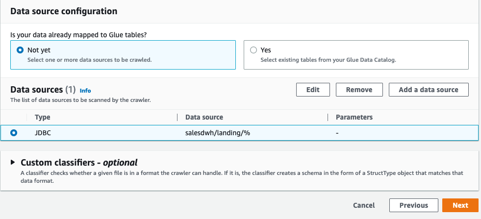
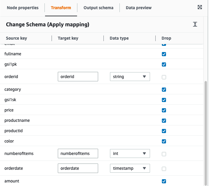
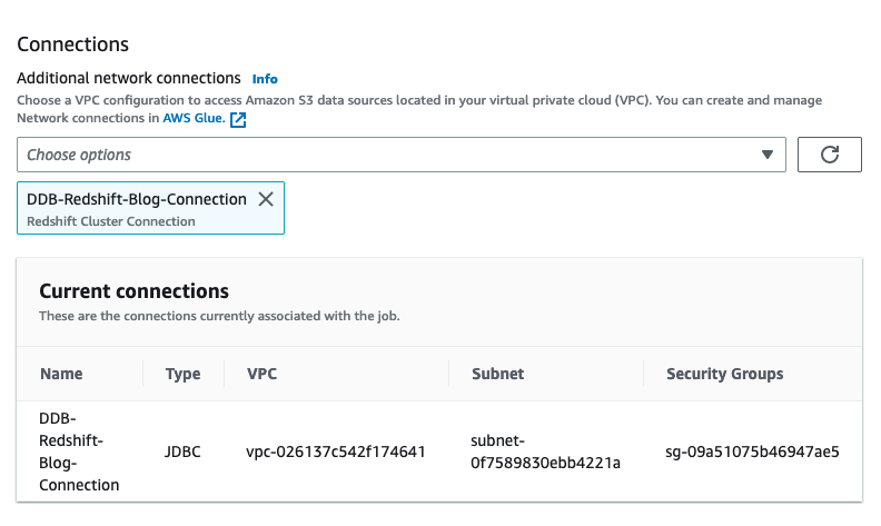
Karthik Ramanathan is a Software Engineer with Amazon Redshift and is based in San Francisco. He brings close to two decades of development experience across the networking, data storage and IoT verticals. When not at work he is also a writer and loves to be in the water.

Albert Harkema is a Software Development Engineer at AWS. He is known for his curiosity and deep-seated desire to understand the inner workings of complex systems. His inquisitive nature drives him to develop software solutions that make life easier for others. Albert’s approach to problem-solving emphasizes efficiency, reliability, and long-term stability, ensuring that his work has a tangible impact. Through his professional experiences, he has discovered the potential of technology to improve everyday life.