Tag Archives: Networking & Content Delivery*

New – Use Amazon S3 Object Lambda with Amazon CloudFront to Tailor Content for End Users

Post Syndicated from Danilo Poccia original https://aws.amazon.com/blogs/aws/new-use-amazon-s3-object-lambda-with-amazon-cloudfront-to-tailor-content-for-end-users/

With S3 Object Lambda, you can use your own code to process data retrieved from Amazon S3 as it is returned to an application. Over time, we added new capabilities to S3 Object Lambda, like the ability to add your own code to S3 HEAD and LIST API requests, in addition to the support for S3 GET requests that was available at launch.

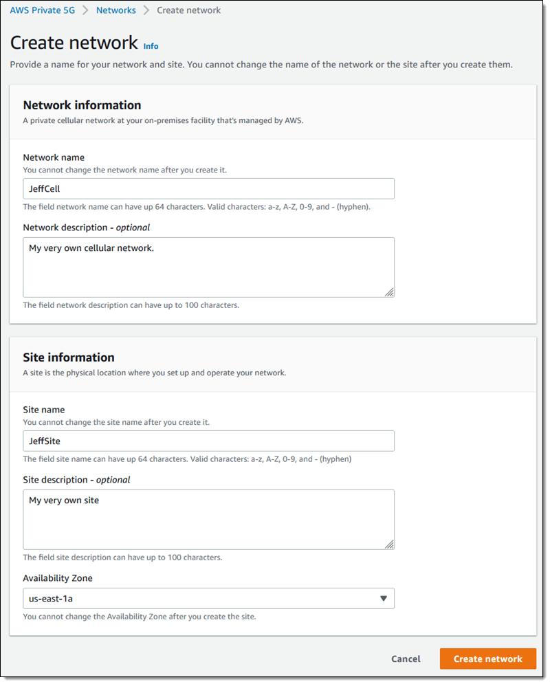
Today, we are launching aliases for S3 Object Lambda Access Points. Aliases are now automatically generated when S3 Object Lambda Access Points are created and are interchangeable with bucket names anywhere you use a bucket name to access data stored in Amazon S3. Therefore, your applications don’t need to know about S3 Object Lambda and can consider the alias to be a bucket name.

Architecture diagram.

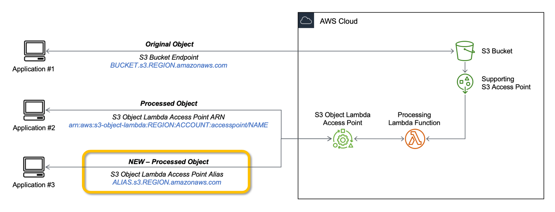
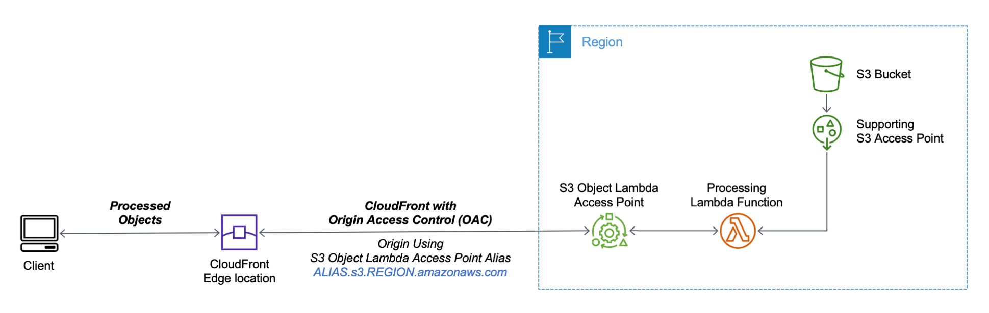
You can now use an S3 Object Lambda Access Point alias as an origin for your Amazon CloudFront distribution to tailor or customize data for end users. You can use this to implement automatic image resizing or to tag or annotate content as it is downloaded. Many images still use older formats like JPEG or PNG, and you can use a transcoding function to deliver images in more efficient formats like WebP, BPG, or HEIC. Digital images contain metadata, and you can implement a function that strips metadata to help satisfy data privacy requirements.

Architecture diagram.

Let’s see how this works in practice. First, I’ll show a simple example using text that you can follow along by just using the AWS Management Console. After that, I’ll implement a more advanced use case processing images.

Using an S3 Object Lambda Access Point as the Origin of a CloudFront Distribution
For simplicity, I am using the same application in the launch post that changes all text in the original file to uppercase. This time, I use the S3 Object Lambda Access Point alias to set up a public distribution with CloudFront.

I follow the same steps as in the launch post to create the S3 Object Lambda Access Point and the Lambda function. Because the Lambda runtimes for Python 3.8 and later do not include the requests module, I update the function code to use urlopen from the Python Standard Library:

import boto3
from urllib.request import urlopen

s3 = boto3.client('s3')

def lambda_handler(event, context):
  print(event)

  object_get_context = event['getObjectContext']
  request_route = object_get_context['outputRoute']
  request_token = object_get_context['outputToken']
  s3_url = object_get_context['inputS3Url']

  # Get object from S3
  response = urlopen(s3_url)
  original_object = response.read().decode('utf-8')

  # Transform object
  transformed_object = original_object.upper()

  # Write object back to S3 Object Lambda
  s3.write_get_object_response(
    Body=transformed_object,
    RequestRoute=request_route,
    RequestToken=request_token)

  return

To test that this is working, I open the same file from the bucket and through the S3 Object Lambda Access Point. In the S3 console, I select the bucket and a sample file (called s3.txt) that I uploaded earlier and choose Open.

Console screenshot.

A new browser tab is opened (you might need to disable the pop-up blocker in your browser), and its content is the original file with mixed-case text:

Amazon Simple Storage Service (Amazon S3) is an object storage service that offers...

I choose Object Lambda Access Points from the navigation pane and select the AWS Region I used before from the dropdown. Then, I search for the S3 Object Lambda Access Point that I just created. I select the same file as before and choose Open.

Console screenshot.

In the new tab, the text has been processed by the Lambda function and is now all in uppercase:

AMAZON SIMPLE STORAGE SERVICE (AMAZON S3) IS AN OBJECT STORAGE SERVICE THAT OFFERS...

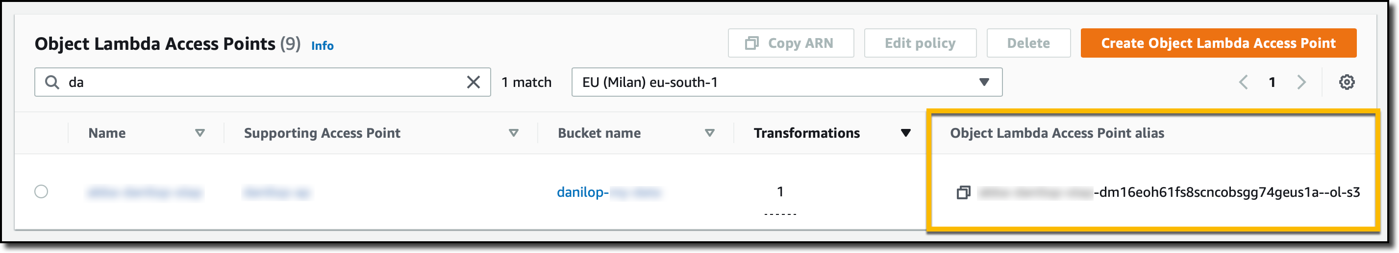
Now that the S3 Object Lambda Access Point is correctly configured, I can create the CloudFront distribution. Before I do that, in the list of S3 Object Lambda Access Points in the S3 console, I copy the Object Lambda Access Point alias that has been automatically created:

Console screenshot.

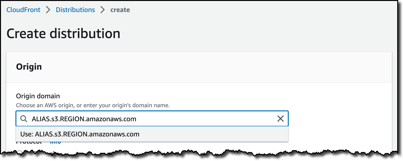
In the CloudFront console, I choose Distributions in the navigation pane and then Create distribution. In the Origin domain, I use the S3 Object Lambda Access Point alias and the Region. The full syntax of the domain is:

ALIAS.s3.REGION.amazonaws.com

Console screenshot.

S3 Object Lambda Access Points cannot be public, and I use CloudFront origin access control (OAC) to authenticate requests to the origin. For Origin access, I select Origin access control settings and choose Create control setting. I write a name for the control setting and select Sign requests and S3 in the Origin type dropdown.

Console screenshot.

Now, my Origin access control settings use the configuration I just created.

Console screenshot.

To reduce the number of requests going through S3 Object Lambda, I enable Origin Shield and choose the closest Origin Shield Region to the Region I am using. Then, I select the CachingOptimized cache policy and create the distribution. As the distribution is being deployed, I update permissions for the resources used by the distribution.

Setting Up Permissions to Use an S3 Object Lambda Access Point as the Origin of a CloudFront Distribution
First, the S3 Object Lambda Access Point needs to give access to the CloudFront distribution. In the S3 console, I select the S3 Object Lambda Access Point and, in the Permissions tab, I update the policy with the following:

{
    "Version": "2012-10-17",
    "Statement": [
        {
            "Effect": "Allow",
            "Principal": {
                "Service": "cloudfront.amazonaws.com"
            },
            "Action": "s3-object-lambda:Get*",
            "Resource": "arn:aws:s3-object-lambda:REGION:ACCOUNT:accesspoint/NAME",
            "Condition": {
                "StringEquals": {
                    "aws:SourceArn": "arn:aws:cloudfront::ACCOUNT:distribution/DISTRIBUTION-ID"
                }
            }
        }
    ]
}

The supporting access point also needs to allow access to CloudFront when called via S3 Object Lambda. I select the access point and update the policy in the Permissions tab:

{
    "Version": "2012-10-17",
    "Id": "default",
    "Statement": [
        {
            "Sid": "s3objlambda",
            "Effect": "Allow",
            "Principal": {
                "Service": "cloudfront.amazonaws.com"
            },
            "Action": "s3:*",
            "Resource": [
                "arn:aws:s3:REGION:ACCOUNT:accesspoint/NAME",
                "arn:aws:s3:REGION:ACCOUNT:accesspoint/NAME/object/*"
            ],
            "Condition": {
                "ForAnyValue:StringEquals": {
                    "aws:CalledVia": "s3-object-lambda.amazonaws.com"
                }
            }
        }
    ]
}

The S3 bucket needs to allow access to the supporting access point. I select the bucket and update the policy in the Permissions tab:

{
    "Version": "2012-10-17",
    "Statement": [
        {
            "Effect": "Allow",
            "Principal": {
                "AWS": "*"
            },
            "Action": "*",
            "Resource": [
                "arn:aws:s3:::BUCKET",
                "arn:aws:s3:::BUCKET/*"
            ],
            "Condition": {
                "StringEquals": {
                    "s3:DataAccessPointAccount": "ACCOUNT"
                }
            }
        }
    ]
}

Finally, CloudFront needs to be able to invoke the Lambda function. In the Lambda console, I choose the Lambda function used by S3 Object Lambda, and then, in the Configuration tab, I choose Permissions. In the Resource-based policy statements section, I choose Add permissions and select AWS Account. I enter a unique Statement ID. Then, I enter cloudfront.amazonaws.com as Principal and select lambda:InvokeFunction from the Action dropdown and Save. We are working to simplify this step in the future. I’ll update this post when that’s available.

Testing the CloudFront Distribution
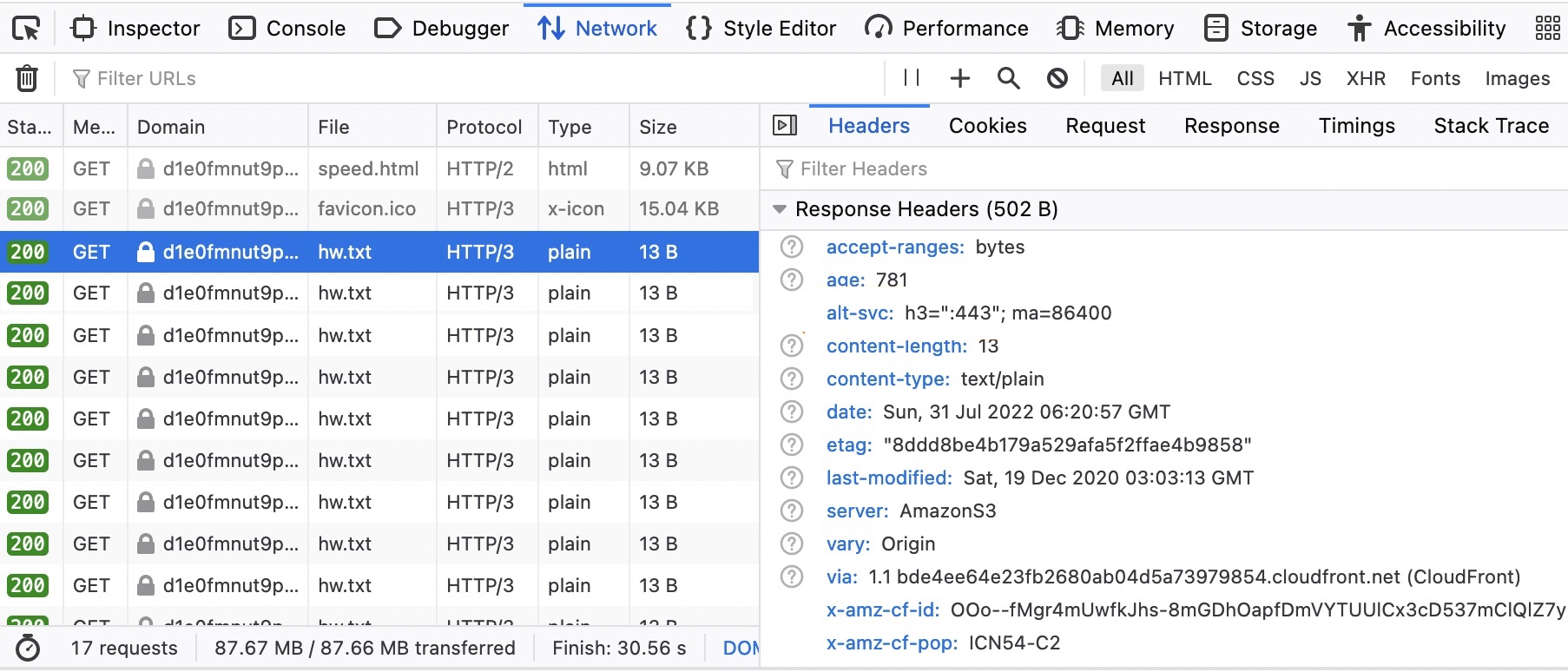
When the distribution has been deployed, I test that the setup is working with the same sample file I used before. In the CloudFront console, I select the distribution and copy the Distribution domain name. I can use the browser and enter https://DISTRIBUTION_DOMAIN_NAME/s3.txt in the navigation bar to send a request to CloudFront and get the file processed by S3 Object Lambda. To quickly get all the info, I use curl with the -i option to see the HTTP status and the headers in the response:

curl -i https://DISTRIBUTION_DOMAIN_NAME/s3.txt

HTTP/2 200 
content-type: text/plain
content-length: 427
x-amzn-requestid: a85fe537-3502-4592-b2a9-a09261c8c00c
date: Mon, 06 Mar 2023 10:23:02 GMT
x-cache: Miss from cloudfront
via: 1.1 a2df4ad642d78d6dac65038e06ad10d2.cloudfront.net (CloudFront)
x-amz-cf-pop: DUB56-P1
x-amz-cf-id: KIiljCzYJBUVVxmNkl3EP2PMh96OBVoTyFSMYDupMd4muLGNm2AmgA==

AMAZON SIMPLE STORAGE SERVICE (AMAZON S3) IS AN OBJECT STORAGE SERVICE THAT OFFERS...

It works! As expected, the content processed by the Lambda function is all uppercase. Because this is the first invocation for the distribution, it has not been returned from the cache (x-cache: Miss from cloudfront). The request went through S3 Object Lambda to process the file using the Lambda function I provided.

Let’s try the same request again:

curl -i https://DISTRIBUTION_DOMAIN_NAME/s3.txt

HTTP/2 200 
content-type: text/plain
content-length: 427
x-amzn-requestid: a85fe537-3502-4592-b2a9-a09261c8c00c
date: Mon, 06 Mar 2023 10:23:02 GMT
x-cache: Hit from cloudfront
via: 1.1 145b7e87a6273078e52d178985ceaa5e.cloudfront.net (CloudFront)
x-amz-cf-pop: DUB56-P1
x-amz-cf-id: HEx9Fodp184mnxLQZuW62U11Fr1bA-W1aIkWjeqpC9yHbd0Rg4eM3A==
age: 3

AMAZON SIMPLE STORAGE SERVICE (AMAZON S3) IS AN OBJECT STORAGE SERVICE THAT OFFERS...

This time the content is returned from the CloudFront cache (x-cache: Hit from cloudfront), and there was no further processing by S3 Object Lambda. By using S3 Object Lambda as the origin, the CloudFront distribution serves content that has been processed by a Lambda function and can be cached to reduce latency and optimize costs.

Resizing Images Using S3 Object Lambda and CloudFront
As I mentioned at the beginning of this post, one of the use cases that can be implemented using S3 Object Lambda and CloudFront is image transformation. Let’s create a CloudFront distribution that can dynamically resize an image by passing the desired width and height as query parameters (w and h respectively). For example:

https://DISTRIBUTION_DOMAIN_NAME/image.jpg?w=200&h=150

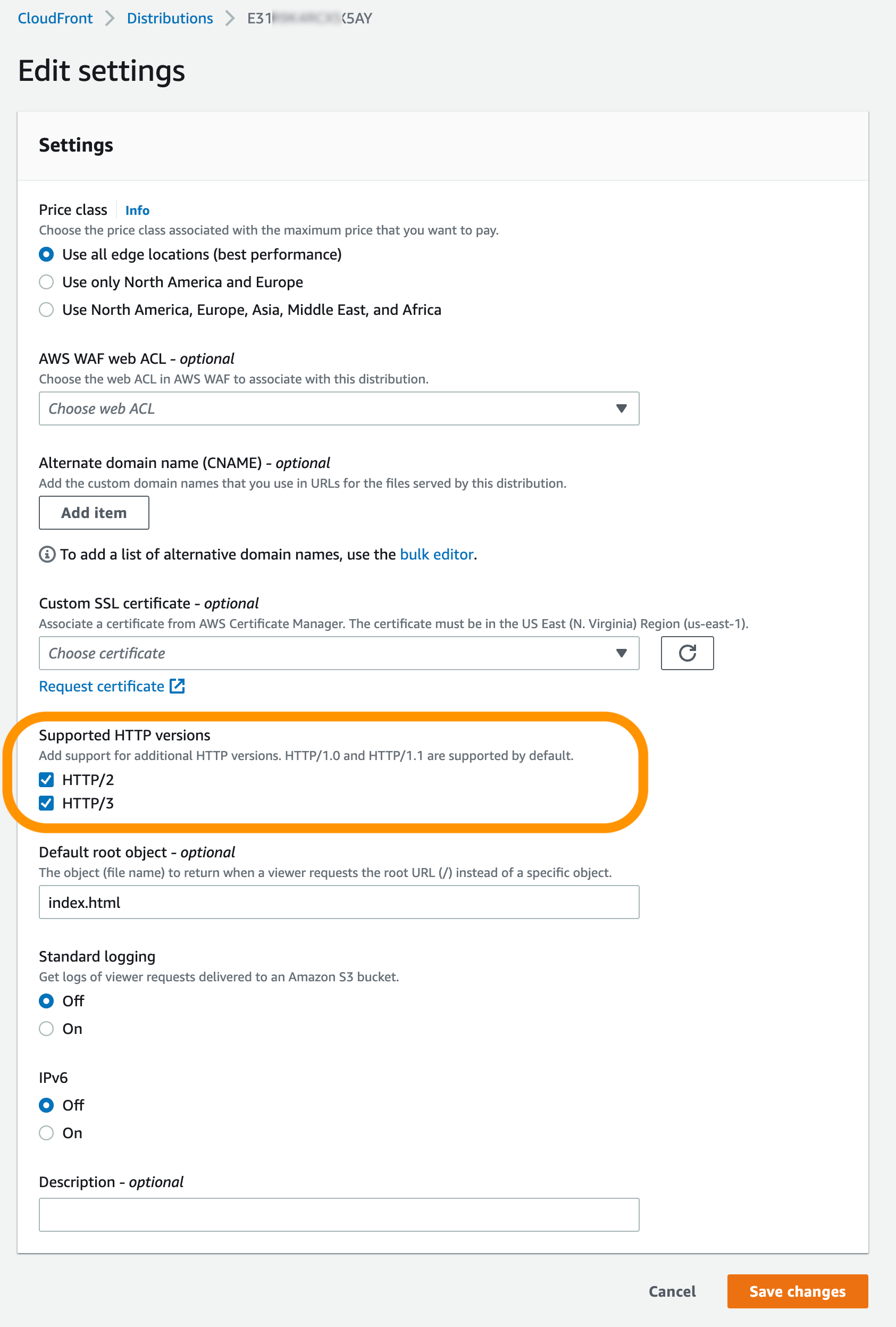
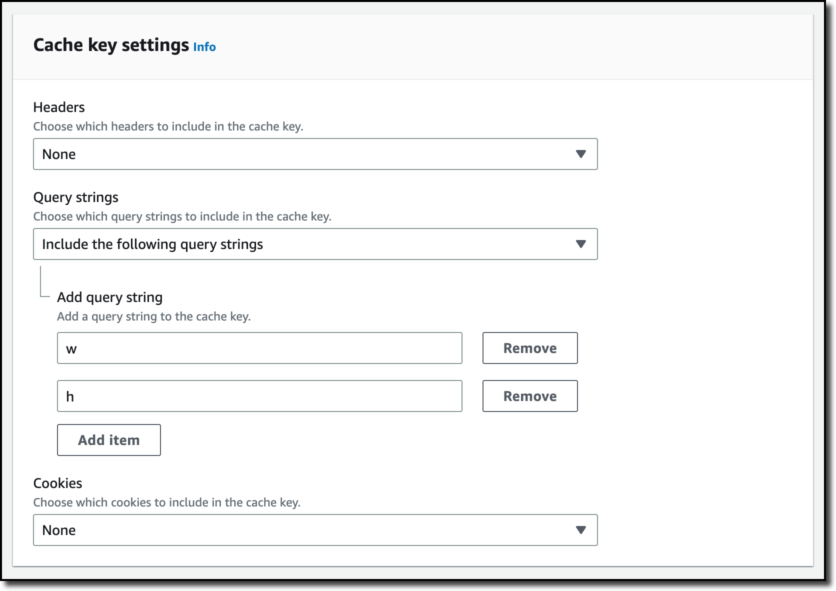
For this setup to work, I need to make two changes to the CloudFront distribution. First, I create a new cache policy to include query parameters in the cache key. In the CloudFront console, I choose Policies in the navigation pane. In the Cache tab, I choose Create cache policy. Then, I enter a name for the cache policy.

Console screenshot.

In the Query settings of the Cache key settings, I select the option to Include the following query parameters and add w (for the width) and h (for the height).

Console screenshot.

Then, in the Behaviors tab of the distribution, I select the default behavior and choose Edit.

There, I update the Cache key and origin requests section:

  • In the Cache policy, I use the new cache policy to include the w and h query parameters in the cache key.
  • In the Origin request policy, use the AllViewerExceptHostHeader managed policy to forward query parameters to the origin.

Console screenshot.

Now I can update the Lambda function code. To resize images, this function uses the Pillow module that needs to be packaged with the function when it is uploaded to Lambda. You can deploy the function using a tool like the AWS SAM CLI or the AWS CDK. Compared to the previous example, this function also handles and returns HTTP errors, such as when content is not found in the bucket.

import io
import boto3
from urllib.request import urlopen, HTTPError
from PIL import Image

from urllib.parse import urlparse, parse_qs

s3 = boto3.client('s3')

def lambda_handler(event, context):
    print(event)

    object_get_context = event['getObjectContext']
    request_route = object_get_context['outputRoute']
    request_token = object_get_context['outputToken']
    s3_url = object_get_context['inputS3Url']

    # Get object from S3
    try:
        original_image = Image.open(urlopen(s3_url))
    except HTTPError as err:
        s3.write_get_object_response(
            StatusCode=err.code,
            ErrorCode='HTTPError',
            ErrorMessage=err.reason,
            RequestRoute=request_route,
            RequestToken=request_token)
        return

    # Get width and height from query parameters
    user_request = event['userRequest']
    url = user_request['url']
    parsed_url = urlparse(url)
    query_parameters = parse_qs(parsed_url.query)

    try:
        width, height = int(query_parameters['w'][0]), int(query_parameters['h'][0])
    except (KeyError, ValueError):
        width, height = 0, 0

    # Transform object
    if width > 0 and height > 0:
        transformed_image = original_image.resize((width, height), Image.ANTIALIAS)
    else:
        transformed_image = original_image

    transformed_bytes = io.BytesIO()
    transformed_image.save(transformed_bytes, format='JPEG')

    # Write object back to S3 Object Lambda
    s3.write_get_object_response(
        Body=transformed_bytes.getvalue(),
        RequestRoute=request_route,
        RequestToken=request_token)

    return

I upload a picture I took of the Trevi Fountain in the source bucket. To start, I generate a small thumbnail (200 by 150 pixels).

https://DISTRIBUTION_DOMAIN_NAME/trevi-fountain.jpeg?w=200&h=150

Picture of the Trevi Fountain with size 200x150 pixels.

Now, I ask for a slightly larger version (400 by 300 pixels):

https://DISTRIBUTION_DOMAIN_NAME/trevi-fountain.jpeg?w=400&h=300

Picture of the Trevi Fountain with size 400x300 pixels.

It works as expected. The first invocation with a specific size is processed by the Lambda function. Further requests with the same width and height are served from the CloudFront cache.

Availability and Pricing
Aliases for S3 Object Lambda Access Points are available today in all commercial AWS Regions. There is no additional cost for aliases. With S3 Object Lambda, you pay for the Lambda compute and request charges required to process the data, and for the data S3 Object Lambda returns to your application. You also pay for the S3 requests that are invoked by your Lambda function. For more information, see Amazon S3 Pricing.

Aliases are now automatically generated when an S3 Object Lambda Access Point is created. For existing S3 Object Lambda Access Points, aliases are automatically assigned and ready for use.

It’s now easier to use S3 Object Lambda with existing applications, and aliases open many new possibilities. For example, you can use aliases with CloudFront to create a website that converts content in Markdown to HTML, resizes and watermarks images, or masks personally identifiable information (PII) from text, images, and documents.

Customize content for your end users using S3 Object Lambda with CloudFront.

Danilo

New – Visualize Your VPC Resources from Amazon VPC Creation Experience

Post Syndicated from Channy Yun original https://aws.amazon.com/blogs/aws/new-visualize-your-vpc-resources-from-amazon-vpc-creation-experience/

Today we are announcing Amazon Virtual Private Cloud (Amazon VPC) resource map, a new feature that simplifies the VPC creation experience in the AWS Management Console. This feature displays your existing VPC resources and their routing visually on a single page, allowing you to quickly understand the architectural layout of the VPC.

A year ago, in March 2022, we launched a new VPC creation experience that streamlines the process of creating and connecting VPC resources. With just one click, even across multiple Availability Zones (AZs), you can create and connect VPC resources, eliminating more than 90 percent of the manual steps required in the past. The new creation experience is centered around an interactive diagram that displays a preview of the VPC architecture and updates as options are selected, providing a visual representation of the resources and their relationships within the VPC that you are about to create.

However, after the creation of the VPC, the diagram that was available during the creation experience that many of our customers loved was no longer available. Today we are changing that! With VPC resource map, you can quickly understand the architectural layout of the VPC, including the number of subnets, which subnets are associated with the public route table, and which route tables have routes to the NAT Gateway.

You can also get to the specific resource details by clicking on the resource. This eliminates the need for you to map out resource relationships mentally and hold the information in your head while working with your VPC, making the process much more efficient and less prone to mistakes.

Getting Started with VPC Resource Map
To get started, choose an existing VPC in the VPC console. In the details section, select the Resource map tab. Here, you can see the resources in your VPC and the relationships between those resources.

As you hover over a resource, you can see the related resources and the connected lines highlighted. If you click to select the resource, you can see a few lines of details and a link to see the details of the selected resource.

Getting Started with VPC Creation Experience
I want to explain how to use the VPC creation experience to improve your workflow to create a new VPC to make a high-availability three-tier VPC easily.

Choose Create VPC and select VPC and more in the VPC console. You can preview the VPC resources that you are about to create all on the same page.

In Name tag auto-generation, you can specify a prefix value for Name tags. This value is used to generate Name tags for all VPC resources in the preview. If I change the default value, which is project to channy, the Name tag in the preview changes to channy- something, such as channy-vpc. You can customize a Name tag per resource in the preview by clicking each resource and making changes.

You can easily change the default CIDR value (10.0.0.0/16) when you click the IPv4 CIDR block field to reveal the CIDR joystick. Use the left or right arrow to move to the previous (9.255.0.0/16) or next (10.0.1.0/16) CIDR block within the /16 network mask. You can also change the subnet mask to /17 by using the down arrow, or go back to /16 using the up arrow.

Choose the number of Availability Zones (AZs) up to 3. The number of public and private subnet types changes based on the number of AZs and shows the total number of each subnet type it will create.

I want a high-availability VPC in three AZs and select 6 for the number of private subnets. In the preview panel, you can see that there are 9 subnets. When I hover over channy-rtb-public, I can visually confirm that this route table is connected to three public subnets and also routed to the internet gateway (channy-igw). The dotted lines indicate routes to network node, and the solid lines indicate relationships such as implicit or explicit associations.

Adding NAT gateways and VPC endpoints is easy. You can simply change the number of NAT gateways in or per Availability Zone (AZ). Note that there is a charge for each NAT gateway. We always recommend having one NAT gateway per AZ and route traffic from subnets in an AZ to the NAT gateway in the same AZ for high availability and to avoid inter-AZ data charges.

To route traffic to Amazon Simple Storage Service (Amazon S3) buckets more securely, you can choose the S3 Gateway endpoint by default. The S3 Gateway endpoint is free of charge and does not use NAT gateways when moving data from private subnets.

You can create additional tags and assign them to all resources in the VPC in no time. I select Add new tag and enter environment for the Key and test for the Value. This key-value pair will be added to every resource here.

Choose Create VPC at the bottom of the page and see the resources and the IDs of those resources that are being created. Before creating, please validate resources from the preview.

Once all the resources are created, choose View VPC at the bottom. The button takes you directly to the VPC resource map, where you can see a visual representation of what you created.

Now Available
Amazon VPC resource map is now available in all AWS Regions where Amazon VPC is available, and you can start using it today.

The VPC resource map and creation experience now only displays VPC, subnets, route tables, internet gateway, NAT gateways, and Amazon S3 gateway. The Amazon VPC console teams and user experience teams will continue to improve the console experience using customer feedback.

To learn more, see the Amazon VPC User Guide, and please send feedback to AWS re:Post for Amazon VPC or through your usual AWS support contacts.

Channy

AWS Verified Access Preview — VPN-less Secure Network Access to Corporate Applications

Post Syndicated from Sébastien Stormacq original https://aws.amazon.com/blogs/aws/aws-verified-access-preview-vpn-less-secure-network-access-to-corporate-applications/

Today, we announced the preview of AWS Verified Access, a new secure connectivity service that allows enterprises to enable local or remote secure access for their corporate applications without requiring a VPN.

Traditionally, remote access to applications when on the road or working from home is granted by a VPN. Once the remote workforce is authenticated on the VPN, they have access to a broad range of applications depending on multiple policies defined in siloed systems, such as the VPN gateway, the firewalls, the identity provider, the enterprise device management solution, etc. These policies are typically managed by different teams, potentially creating overlaps, making it difficult to diagnose application access issues. Internal applications often rely on older authentication protocols, like Kerberos, that were built with the LAN in mind, instead of modern protocols, like OIDC, that are better tuned to modern enterprise patterns. Customers told us that policy updates can take months to roll out.

Verified Access is built using the AWS Zero Trust security principles. Zero Trust is a conceptual model and an associated set of mechanisms that focus on providing security controls around digital assets that do not solely or fundamentally depend on traditional network controls or network perimeters.

Verified Access improves your organization’s security posture by leveraging multiple security inputs to grant access to applications. It grants access to applications only when users and their devices meet the specified security requirements. Examples of inputs are the user identity and role or the device security posture, among others. Verified Access validates each application request, regardless of user or network, before granting access. Having each application access request evaluated allows Verified Access to adapt the security posture based on changing conditions. For example, if the device security signals that your device posture is out of compliance, then Verified Access will not allow you to access the application anymore.

In my opinion, there are three main benefits when adopting Verified Access:

It is easy to use for IT administrators. As an IT Administrator, you can now easily set up applications for secure remote access. It provides a single configuration point to manage and enforce a multisystem security policy to allow or deny access to your corporate applications.

It provides an open ecosystem that allows you to retain your existing identity provider and device management system. I listed all our partners at the end of this post.

It is easy to use for end users. This is my preferred one. Your workforce is not required to use a VPN client anymore. A simple browser plugin is enough to securely grant access when the user and the device are identified and verified. As of today, we support Chrome and Firefox web browsers. This is something about which I can share my personal experience. Amazon adopted a VPN-less strategy a few years ago. It’s been a relief for my colleagues and me to be able to access most of our internal web applications without having to start a VPN client and keep it connected all day long.

Let’s See It in Action
I deployed a web server in a private VPC and exposed it to my end users through a private application load balancer (https://demo.seb.go-aws.com). I created a TLS certificate for the application external endpoint (secured.seb.go-aws.com). I also set up AWS Identity Center (successor of AWS SSO). In this demo, I will use it as a source for user identities. Now I am ready to expose this application to my remote workforce.

Verified Access - Demo application

Creating a Verified Access endpoint is a four-step process. To get started, I navigate to the VPC page of the AWS Management Console. I first create the trust provider. A trust provider maintains and manages identity information for users and devices. When an application request is made, the identity information sent by the trust provider will be evaluated by Verified Access before allowing or denying the application request. I select Verified Access trust provider on the left-side navigation pane.

Verified Access navigation menu

On the Create Verified Access trust provider page, I enter a Name and an optional Description. I enter the Policy reference name, an identifier that will be used when working with policy rules. I select the source of trust: User trust provider. For this demo, I select IAM Identity Center as the source of trust for user identities. Verified Access also works with other OpenID Connect-compliant providers. Finally, I select Create Verified Access trust provider.

Verified Access - Create trust provider

I may repeat the operation when I have multiple trust providers. For example, I might have an identity-based trust provider to verify the identity of my end users and a device-based trust provider to verify the security posture of their devices.

I then create the Verified Identity instance. A Verified Access instance is a Regional AWS entity that evaluates application requests and grants access only when your security requirements are met.

On the Create Verified Access instance page, I enter a Name and an optional Description. I select the trust provider I just created. I can add additional trust provider types once the Verified Access instance is created.

Verified Access - Create instance

Third, I create a Verified Access group.

A Verified Access group is a collection of applications that have similar security requirements. Each application within a Verified Access group shares a group-level policy. For example, you can group together all applications for “finance” users and use one common policy. This simplifies your policy management. You can use a single policy for a group of applications with similar access needs.

On the Create Verified Access group page, I enter a Name only. I will enter a policy at a later stage.

Verified Access - Create access groupThe fourth and last step before testing my setup is to create the endpoint.

A Verified Access endpoint is a regional resource that specifies the application that Verified Access will be providing access to. This is where your end users connect to. Each endpoint has its own DNS name and TLS certificate. After having evaluated incoming requests, the endpoint forwards authorized requests to your internal application, either an internal load balancer or a network interface. Verified Access supports network-level and application-level load balancers.

On the Create Verified Access endpoint page, I enter a Name and Description. I reference the Verified Access group that I just created.

In the Application details section, under Application domain, I enter the DNS name end users will use to access the application. For this demo, I use secured.seb.go-aws.com. Under Domain certificate ARN, I select a TLS certificate matching the DNS name. I created the certificate using AWS Certificate Manager.

Verified Access - Create endpoint - part 1

On the Endpoint details section, I select VPC as Attachment type. I select one or multiple Security groups to attach to this endpoint. I enter awsnewsblog as Endpoint domain prefix. I select load balancer as Endpoint type. I select the Protocol (HTTP), then I enter the Port (80). I select the Load balancer ARN and the private Subnets where my load balancer is deployed.

Verified Access - Create endpoint - part 2

Again, I leave the Policy details section empty. I will define a policy in the group instead. When I am done, I select Create Verified Access endpoint. It might take a few minutes to create.

Verified Access - Create endpoint - part 3

Now it is time to grab a coffee and stretch my legs. When I return, I see the Verified Access endpoint is ✅ Active. I copy the Endpoint domain and add it as a CNAME record to my application DNS name (secured.seb.go-aws.com). I use Amazon Route 53 for this, but you can use your existing DNS server as well.

Verified Access - endpoint detailsThen, I point my favorite browser to https://secured.seb.go-aws.com. The browser is redirected to IAM Identity Center (formerly AWS SSO). I enter the username and password of my test user. I am not adding a screenshot for this. After the redirection, I receive the error message : Unauthorized. This is expected because there is no policy defined on the Verified Access endpoint. It denies every request by default.

On the Verified Access groups page, I select the Policy tab. Then I select the Modify Verified Access endpoint policy button to create an access policy.

Verified Access - group policy tab

I enter a policy allowing anybody authenticated and having an email address ending with @amazon.com. This is the email address I used for the user defined in AWS Identity Center. Note that the name after context is the name I entered as Policy reference name when I created the Verified Access trust provider. The documentation page has the details of the policy syntax, the attributes, and the operators I can use.

permit(principal, action, resource)
when {
    context.awsnewsblog.user.email.address like "*@amazon.com"
};

Verified Access - group define policy

After a few minutes, Verified Access updates the policy and becomes Active again. I force my browser to refresh, and I see the internal application now available to my authenticated user.

Verified Access - access granted


Pricing and Availability

AWS Verified Access is now available in preview in 10 AWS Regions: US East (Ohio, N. Virginia), US West (N. California, Oregon), Asia Pacific (Sydney), Canada (Central), Europe (Ireland, London, Paris), and South America (São Paulo).

As usual, pricing is based on your usage. There is no upfront or fixed price. We charge per application (Verified Access endpoint) per hour, with tiers depending on the number of applications. Prices start in US East (N. Virginia) Region at $0.27 per verified Access endpoint and per hour. This price goes down to $0.20 per endpoint per hour when you have more than 200 applications.

On top of this, there is a charge of $0.02 per GB for data processed by Verified Access. You also incur standard AWS data transfer charges for all data transferred using Verified Access.

This billing model makes it easy to start small and then grow at your own pace.

Go and configure your first Verified Access access point today.

— seb

Introducing VPC Lattice – Simplify Networking for Service-to-Service Communication (Preview)

Post Syndicated from Danilo Poccia original https://aws.amazon.com/blogs/aws/introducing-vpc-lattice-simplify-networking-for-service-to-service-communication-preview/

Modern applications are built using modular and distributed components. Each component is a service that implements its own subset of functionalities. To make these services communicate with each other, you need a way to let them discover where they are, authorize access, and route traffic. When troubleshooting issues, you need to keep communication configurations under control so that you can quickly understand what is happening at the application, service, and network levels. This can take a lot of your time.

Today, we are making available in preview Amazon VPC Lattice, a new capability of Amazon Virtual Private Cloud (Amazon VPC) that gives you a consistent way to connect, secure, and monitor communication between your services. With VPC Lattice, you can define policies for traffic management, network access, and monitoring so you can connect applications in a simple and consistent way across AWS compute services (instances, containers, and serverless functions). VPC Lattice automatically handles network connectivity between VPCs and accounts and network address translation between IPv4, IPv6, and overlapping IP addresses. VPC Lattice integrates with AWS Identity and Access Management (IAM) to give you the same authentication and authorization capabilities you are familiar with when interacting with AWS services today, but for your own service-to-service communication. With VPC Lattice, you have common controls to route traffic based on request characteristics and weighted routing for blue/green and canary-style deployments. For example, VPC Lattice allows you to mix and match compute types for a given service, which helps you modernize a monolith application architecture to microservices.

VPC Lattice is designed to be noninvasive, allowing teams across your organization to incrementally opt in over time. In this way, you are able to deliver applications faster by focusing on your application logic, while VPC Lattice handles service-to-service networking, security, and monitoring requirements.

How Amazon VPC Lattice Works
With VPC Lattice, you create a logical application layer network, called a service network, that connects clients and services across different VPCs and accounts, abstracting network complexity. A service network is a logical boundary that is used to automatically implement service discovery and connectivity as well as apply access and observability policies to a collection of services. It offers inter-application connectivity over HTTP/HTTPS and gRPC protocols within a VPC.

Once a VPC has been enabled for a service network, clients in the VPC will automatically be able to discover the services in the service network through DNS and will direct all inter-application traffic through VPC Lattice. You can use AWS Resource Access Manager (RAM) to control which accounts, VPCs, and applications can establish communication via VPC Lattice.

A service is an independently deployable unit of software that delivers a specific task or function. In VPC Lattice, a service is a logical component that can live in any VPC or account and can run on a mixture of compute types (virtual machines, containers, and serverless functions). A service configuration consists of:

  • One or two listeners that define the port and protocol that the service is expecting traffic on. Supported protocols are HTTP/1.1, HTTP/2, and gRPC, including HTTPS for TLS-enabled services.
  • Listeners have rules that consist of a priority, which specifies the order in which rules should be processed, one or more conditions that define when to apply the rule, and actions that forward traffic to target groups. Each listener has a default rule that takes effect when no additional rules are configured, or no conditions are met.
  • A target group is a collection of targets, or compute resources, that are running a specific workload you are trying to route toward. Targets can be Amazon Elastic Compute Cloud (Amazon EC2) instances, IP addresses, and Lambda functions. For Kubernetes workloads, VPC Lattice can target services and pods via the AWS Gateway Controller for Kubernetes. To have access to the AWS Gateway Controller for Kubernetes, you can join the preview.

VPC Lattice logical architecture.

To configure service access controls, you can use access policies. An access policy is an IAM resource policy that can be associated with a service network and individual services. With access policies, you can use the “PARC” (principal, action, resource, and condition) model to enforce context-specific access controls for services. For example, you can use an access policy to define which services can access a service you own. If you use AWS Organizations, you can limit access to a service network to a specific organization.

VPC Lattice also provides a service directory, a centralized view of the services that you own or have been shared with you via AWS RAM.

Using Amazon VPC Lattice
We expect people with different roles can use VPC Lattice. For example:

  • The service network administrator can:
    • Create and manage a service network.
    • Define access and monitoring for the service network.
    • Associate client and services.
    • Share the service network with other AWS accounts.
  • The service owner can:
    • Create and manage a service, including access and monitoring.
    • Define routing, for example, configuring listeners and rules that point to the target groups where the service is running.
    • Associate a service to service networks.

Let’s see how this works in practice. In this quick walkthrough, I am covering both roles.

Creating Two Backend Services
There is nothing specific to VPC Lattice in this section. I am just creating a couple of services, one running on Amazon EC2 and one on AWS Lambda, that I’ll use later when I configure networking with VPC Lattice.

In an Amazon Linux EC2 instance, I create a web app that replies “Hello from the instance” to HTTP requests. To allow access to the instance from clients coming via VPC Lattice, I add an inbound rule to the security group to allow TCP traffic on port 8080 from the VPC Lattice AWS-managed prefix list.

Here’s the app.py file. I am using Python and Flask for this app, but you don’t need to know them to follow along with the post.

from flask import Flask

app = Flask(__name__)

@app.route('/')
def index():
  return 'Hello from the instance'

@app.route('/<path>')
def somePath(path):
  return 'Hello from the instance at path "{}"'.format(path)

app.run(host='0.0.0.0', port=8080)

Here’s the requirements.txt file with the Python dependencies. There’s only one line because the only module I need is flask:

flask

I install the dependencies:

pip3 install -r requirements.txt

Then, I start the web app using the nohup command to keep it running in case I log out of the instance:

nohup flask run --host=0.0.0.0 --port 8080 &

On the EC2 instance, the web service is now listening to HTTP traffic on port 8080.

In the Lambda console, I create a simple function using the Node.js 18.x runtime that replies “Hello from the function” to all invocations.

exports.handler = async (event) => {
    const response = {
        statusCode: 200,
        body: JSON.stringify('Hello from the function'),
    };
    return response;
};

The two services are now both ready. Let’s use VPC Lattice to configure networking.

Creating VPC Lattice Target Groups
I start by creating two target groups, one for the EC2 instance and one for the Lambda function. In the VPC console, there is a new VPC Lattice section in the navigation pane. There, I choose Target groups and then Create target group.

For the first target group, I choose the Instances target type and enter a name.

Console screenshot.

I choose the protocol (HTTP) and port (8080) used by the web app running on the instance. I select the VPC where the instance is running and the protocol version (HTTP1).

Console screenshot.

Now I can configure the health check that will be used to test the target status. In this case, I use the default values proposed by the console.

Console screenshot.

In the next step, I can register the targets. I select the instance on which the web app is running from the list and choose to include it.

Console screenshot.

I review the selected targets (one instance in this case) and choose Submit.

In a similar way, I create a target group for the Lambda function. This time, I select the function from the list. I can choose which function version or function alias to use. For simplicity, I use the $LATEST version.

Console screenshot.

Creating VPC Lattice Services
Now that the target groups are ready, I choose Services in the navigation pane and then Create service. I enter a name and a description.

Console screenshot.

Now, I can choose the authentication type. If I choose None, the service network does not authenticate or authorize client access, and the auth policy, if present, is not used. I select AWS IAM and then, from the Apply policy template dropdown, the template that allows both authenticated and unauthenticated access.

Console screenshot.

In the Monitoring section, I turn on Access logs. As the destination for the access logs, I use an Amazon CloudWatch Log group that I created before. I also have the option to use an Amazon Simple Storage Service (Amazon S3) bucket or a Amazon Kinesis Data Firehose delivery stream.

Console screenshot.

In the next step, I define routing for the service. I choose Add listener. For the protocol, I configure the service to listen using HTTPS. In the default action, I choose to send two-thirds (Weight 20) of the requests to the instance target group and one-third (Weight 10) to the function target group.

Console screenshot.

Then, I add two additional rules. The first rule (Priority 10) sends all requests where the path is /to-instance to the instance target group.

Console screenshot.

The second rule (Priority 20) sends all traffic where the path is /to-function to the function target group.

Console screenshot.

In the next step, I am asked to associate the service with one or more service networks. I didn’t create a service network yet, so I skip this step for now and choose Next. I review the configuration and create the service.

Creating VPC Lattice Service Networks
Now, I create the service network so that I can associate the service and the VPCs I want to use. I choose Service network from the navigation pane and then Create service network. I enter a name and a description for the service network.

Console screenshot.

In the Associate services, I select the service I just created.

Console screenshot.

In the VPC associations, I select the VPC used by the instance where the web app runs. This can help in the future because it allows the web app to call other services associated with the service network.

Console screenshot.

Then, I select a second VPC where I have another EC2 instance that I want to use to run some tests.

Console screenshot.

For simplicity, in the Access section, I select the None auth type.

Console screenshot.

In the Monitoring section, I choose to send the access logs for the whole service network to an S3 bucket.

Console screenshot.

I review the summary of the configuration and create the service network. After a few seconds all service and VPC associations are active, and I can start using the service.

I write down the domain name of the service from the list of service associations.

Console screenshot.

Testing Access to the Service Using VPC Lattice
I look at the Routing tab of the service to find a nice recap of how the listener is handling routing towards the different target groups.

Console screenshot.

Then, I log into the EC2 instance in my second VPC and use curl to call the service domain name. As expected, I get about two-thirds of the responses from the instance and one-third from the function.

curl https://my-service-03e92ee54968d87ca.7d67968.vpc-lattice-svcs.us-west-2.on.aws
Hello from the instance

curl https://my-service-03e92ee54968d87ca.7d67968.vpc-lattice-svcs.us-west-2.on.aws
Hello from the instance

curl https://my-service-03e92ee54968d87ca.7d67968.vpc-lattice-svcs.us-west-2.on.aws
"Hello from the function"

When I call the /to-instance and /to-function paths, the additional rules forward the requests to the instance and the function, respectively.

curl https://my-service-03e92ee54968d87ca.7d67968.vpc-lattice-svcs.us-west-2.on.aws/to-instance
Hello from the instance "to-instance" path

curl https://my-service-03e92ee54968d87ca.7d67968.vpc-lattice-svcs.us-west-2.on.aws/to-function
"Hello from the function"

I can now review access to my service using the access log subscriptions I configured before.

For the service, I look in the CloudWatch Log group. There, I find a log stream containing detailed access information about the service.

Console screenshot.

The access log for all services associated with the service network is on the S3 bucket. I have only one service for now, but more are coming.

Console screenshot.

Available in Preview
Amazon VPC Lattice is available in preview in the US West (Oregon) Region.

VPC Lattice provides deployment consistency across AWS compute types so that you can connect your services across instances, containers, and serverless functions. You can use VPC Lattice to apply granular and rich traffic controls, such as policy-based routing and weighted targets to support blue/green and canary-style deployments.

VPC Lattice allows monitoring and troubleshooting service-to-service communication with detailed access logs and metrics that capture request type, volume of traffic, error rates, response time, and more. In this blog post, I only scratched the surface of what you can do with VPC Lattice.

Simplify the way you connect, secure, and monitor service-to-service communication with Amazon VPC Lattice.

New – ENA Express: Improved Network Latency and Per-Flow Performance on EC2

Post Syndicated from Jeff Barr original https://aws.amazon.com/blogs/aws/new-ena-express-improved-network-latency-and-per-flow-performance-on-ec2/

We know that you can always make great use of all available network bandwidth and network performance, and have done our best to supply it to you. Over the years, network bandwidth has grown from the 250 Mbps on the original m1 instance to 200 Gbps on the newest m6in instances. In addition to raw bandwidth, we have also introduced advanced networking features including Enhanced Networking, Elastic Network Adapters (ENAs), and (for tightly coupled HPC workloads) Elastic Fabric Adapters (EFAs).

Introducing ENA Express
Today we are launching ENA Express. Building on the Scalable Reliable Datagram (SRD) protocol that already powers Elastic Fabric Adapters, ENA Express reduces P99 latency of traffic flows by up to 50% and P99.9 latency by up to 85% (in comparison to TCP), while also increasing the maximum single-flow bandwidth from 5 Gbps to 25 Gbps. Bottom line, you get a lot more per-flow bandwidth and a lot less variability.

You can enable ENA Express on new and existing ENAs and take advantage of this performance right away for TCP and UDP traffic between c6gn instances running in the same Availability Zone.

Using ENA Express
I used a pair of c6gn instances to set up and test ENA Express. After I launched the instances I used the AWS Management Console to enable ENA Express for both instances. I find each ENI, select it, and choose Manage ENA Express from the Actions menu:

I enable ENA Express and ENA Express UDP and click Save:

Then I set the Maximum Transmission Unit (MTU) to 8900 on both instances:

$ sudo /sbin/ifconfig eth0 mtu 8900

I install iperf3 on both instances, and start the first one in server mode:

$ iperf3 -s
-----------------------------------------------------------
Server listening on 5201
-----------------------------------------------------------

Then I run the second one in client mode and observe the results:

$ iperf3 -c 10.0.178.46
Connecting to host 10.0.178.46, port 5201
[  4] local 10.0.187.74 port 35622 connected to 10.0.178.46 port 5201
[ ID] Interval           Transfer     Bandwidth       Retr  Cwnd
[  4]   0.00-1.00   sec  2.80 GBytes  24.1 Gbits/sec    0   1.43 MBytes
[  4]   1.00-2.00   sec  2.81 GBytes  24.1 Gbits/sec    0   1.43 MBytes
[  4]   2.00-3.00   sec  2.80 GBytes  24.1 Gbits/sec    0   1.43 MBytes
[  4]   3.00-4.00   sec  2.81 GBytes  24.1 Gbits/sec    0   1.43 MBytes
[  4]   4.00-5.00   sec  2.81 GBytes  24.1 Gbits/sec    0   1.43 MBytes
[  4]   5.00-6.00   sec  2.80 GBytes  24.1 Gbits/sec    0   1.43 MBytes
[  4]   6.00-7.00   sec  2.80 GBytes  24.1 Gbits/sec    0   1.43 MBytes
[  4]   7.00-8.00   sec  2.81 GBytes  24.1 Gbits/sec    0   1.43 MBytes
[  4]   8.00-9.00   sec  2.81 GBytes  24.1 Gbits/sec    0   1.43 MBytes
[  4]   9.00-10.00  sec  2.81 GBytes  24.1 Gbits/sec    0   1.43 MBytes
- - - - - - - - - - - - - - - - - - - - - - - - -
[ ID] Interval           Transfer     Bandwidth       Retr
[  4]   0.00-10.00  sec  28.0 GBytes  24.1 Gbits/sec    0             sender
[  4]   0.00-10.00  sec  28.0 GBytes  24.1 Gbits/sec                  receiver

The ENA driver reports on metrics that I can review to confirm the use of SRD:

ethtool -S eth0 | grep ena_srd
     ena_srd_mode: 3
     ena_srd_tx_pkts: 25858313
     ena_srd_eligible_tx_pkts: 25858323
     ena_srd_rx_pkts: 2831267
     ena_srd_resource_utilization: 0

The metrics work as follows:

  • ena_srd_mode indicates that SRD is enabled for TCP and UDP.
  • ena_srd_tx_pkts denotes the number of packets that have been transmitted via SRD.
  • ena_srd_eligible_pkts denotes the number of packets that were eligible for transmission via SRD. A packet is eligible for SRD if ENA-SRD is enabled on both ends of the connection, both connections reside in the same Availability Zone, and the packet is using either UDP or TCP.
  • ena_srd_rx_pkts denotes the number of packets that have been received via SRD.
  • ena_srd_resource_utilization denotes the percent of allocated Nitro network card resources that are in use, and is proportional to the number of open SRD connections. If this value is consistently approaching 100%, scaling out to more instances or scaling up to a larger instance size may be warranted.

Thing to Know
Here are a couple of things to know about ENA Express and SRD:

Access – I used the Management Console to enable and test ENA Express; CLI, API, CloudFormation and CDK support is also available.

Fallback – If a TCP or UDP packet is not eligible for transmission via SRD, it will simply be transmitted in the usual way.

UDP – SRD takes advantage of multiple network paths and “sprays” packets across them. This would normally present a challenge for applications that expect packets to arrive more or less in order, but ENA Express helps out by putting the UDP packets back into order before delivering them to you, taking the burden off of your application. If you have built your own reliability layer over UDP, or if your application does not require packets to arrive in order, you can enable ENA Express for TCP but not for UDP.

Instance Types and Sizes – We are launching with support for the 16xlarge size of the c6gn instances, with additional instance families and sizes in the works.

Resource Utilization – As I hinted at above, ENA Express uses some Nitro card resources to process packets. This processing also adds a few microseconds of latency per packet processed, and also has a moderate but measurable effect on the maximum number of packets that a particular instance can process per second. In situations where high packet rates are coupled with small packet sizes, ENA Express may not be appropriate. In all other cases you can simply enable SRD to enjoy higher per-flow bandwidth and consistent latency.

Pricing – There is no additional charge for the use of ENA Express.

Regions – ENA Express is available in all commercial AWS Regions.

All About SRD
I could write an entire blog post about SRD, but my colleagues beat me to it! Here are some great resources to help you to learn more:

A Cloud-Optimized Transport for Elastic and Scalable HPC – This paper reviews the challenges that arise when trying to run HPC traffic across a TCP-based network, and points out that the variability (latency outliers) can have a profound effect on scaling efficiency, and includes a succinct overview of SRD:

Scalable reliable datagram (SRD) is optimized for hyper-scale datacenters: it provides load balancing across multiple paths and fast recovery from packet drops or link failures. It utilizes standard ECMP functionality on the commodity Ethernet switches and works around its limitations: the sender controls the ECMP path selection by manipulating packet encapsulation.

There’s a lot of interesting detail in the full paper, and it is well worth reading!

In the Search for Performance, There’s More Than One Way to Build a Network – This 2021 blog post reviews our decision to build the Elastic Fabric Adapter, and includes some important data (and cool graphics) to demonstrate the impact of packet loss on overall application performance. One of the interesting things about SRD is that it keeps track of the availability and performance of multiple network paths between transmitter and receiver, and sprays packets across up to 64 paths at a time in order to take advantage of as much bandwidth as possible and to recover quickly in case of packet loss.

Jeff;

Our guide to AWS Compute at re:Invent 2022

Post Syndicated from Sheila Busser original https://aws.amazon.com/blogs/compute/our-guide-to-aws-compute-at-reinvent-2022/

This blog post is written by Shruti Koparkar, Senior Product Marketing Manager, Amazon EC2.

AWS re:Invent is the most transformative event in cloud computing and it is starting on November 28, 2022. AWS Compute team has many exciting sessions planned for you covering everything from foundational content, to technology deep dives, customer stories, and even hands on workshops. To help you build out your calendar for this year’s re:Invent, let’s look at some highlights from the AWS Compute track in this blog. Please visit the session catalog for a full list of AWS Compute sessions.

Learn what powers AWS Compute

AWS offers the broadest and deepest functionality for compute. Amazon Elastic Cloud Compute (Amazon EC2) offers granular control for managing your infrastructure with the choice of processors, storage, and networking.

The AWS Nitro System is the underlying platform for our all our modern EC2 instances. It enables AWS to innovate faster, further reduce cost for our customers, and deliver added benefits like increased security and new instance types.

Discover the benefits of AWS Silicon

AWS has invested years designing custom silicon optimized for the cloud. This investment helps us deliver high performance at lower costs for a wide range of applications and workloads using AWS services.

  • Explore the AWS journey into silicon innovation with our “CMP201: Silicon Innovation at AWS” session. We will cover some of the thought processes, learnings, and results from our experience building silicon for AWS Graviton, AWS Nitro System, and AWS Inferentia.
  • To learn about customer-proven strategies to help you make the move to AWS Graviton quickly and confidently while minimizing uncertainty and risk, attend “CMP410: Framework for adopting AWS Graviton-based instances”.

 Explore different use cases

Amazon EC2 provides secure and resizable compute capacity for several different use-cases including general purpose computing for cloud native and enterprise applications, and accelerated computing for machine learning and high performance computing (HPC) applications.

High performance computing

  • HPC on AWS can help you design your products faster with simulations, predict the weather, detect seismic activity with greater precision, and more. To learn how to solve world’s toughest problems with extreme-scale compute come join us for “CMP205: HPC on AWS: Solve complex problems with pay-as-you-go infrastructure”.
  • Single on-premises general-purpose supercomputers can fall short when solving increasingly complex problems. Attend “CMP222: Redefining supercomputing on AWS” to learn how AWS is reimagining supercomputing to provide scientists and engineers with more access to world-class facilities and technology.
  • AWS offers many solutions to design, simulate, and verify the advanced semiconductor devices that are the foundation of modern technology. Attend “CMP320: Accelerating semiconductor design, simulation, and verification” to hear from ARM and Marvel about how they are using AWS to accelerate EDA workloads.

Machine Learning

Cost Optimization

Hear from our customers

We have several sessions this year where AWS customers are taking the stage to share their stories and details of exciting innovations made possible by AWS.

Get started with hands-on sessions

Nothing like a hands-on session where you can learn by doing and get started easily with AWS compute. Our speakers and workshop assistants will help you every step of the way. Just bring your laptop to get started!

You’ll get to meet the global cloud community at AWS re:Invent and get an opportunity to learn, get inspired, and rethink what’s possible. So build your schedule in the re:Invent portal and get ready to hit the ground running. We invite you to stop by the AWS Compute booth and chat with our experts. We look forward to seeing you in Las Vegas!

New – Direct VPC Routing Between On-Premises Networks and AWS Outposts Rack

Post Syndicated from Steve Roberts original https://aws.amazon.com/blogs/aws/new-direct-vpc-routing-between-on-premises-networks-and-aws-outposts-rack/

Today, we announced direct VPC routing for AWS Outposts rack. This enables you to connect Outposts racks and on-premises networks using simplified IP address management. Direct VPC routing automatically advertises Amazon Virtual Private Cloud (Amazon VPC) subnet CIDR addresses to on-premises networks. This enables you to use the private IP addresses of resources in your VPC when communicating with your on-premises network. Furthermore, you can enable direct VPC routing using a self-serve process without needing to contact AWS.

AWS Outposts rack

If you’re unfamiliar, AWS Outposts rack, a part of the Outposts family, is a fully-managed service that offers the same AWS infrastructure, AWS services, APIs, and tools to virtually any on-premises datacenter or co-location space for a consistent hybrid experience. They’re ideal for workloads that require low-latency access to on-premises systems, local data processing, data residency, and migration of applications with local system interdependencies. Once installed, your Outposts rack becomes an extension of your VPC, and it’s managed using the same APIs, tools, and management controls that you already use in the cloud.

With direct VPC routing, you now have two options to configure and connect your Outposts rack to your on-premises networks. Previously, to configure network routing between an on-premises network and an Outposts rack, you needed to use Customer-owned IP addresses (CoIP). During an Outposts rack installation, this involved providing a separate IP address range/CIDR from your on-premises network for AWS to create an address pool, which is known as a CoIP pool. When an Amazon Elastic Compute Cloud (Amazon EC2) instance on your Outposts rack needed to communicate with your on-premises network, Outposts rack would perform a 1:1 network address translation (NAT) from the VPC private IP address to a CoIP address in the CoIP pool. Using CoIP means that you must manage both VPC and CoIP address pools, without overlap, and configure route propagation between the two sets of addresses. When adding a subnet to a VPC, you also needed to follow several steps to update route propagation between your networks to recognize the new subnet addresses.

Managing IP address ranges for AWS cloud and onsite resources, as well as dealing with CoIP ranges on Outposts rack, can be an operational burden. Although the option to use CoIP is still available and will continue to be fully supported, the new direct VPC routing option simplifies your IP address management. Automatic advertisement of CIDR addresses for subnets, including new subnets added in the future, between the VPC and your Outposts rack, removes the need for you to reconfigure IP addresses. This also keeps route propagation up-to-date, thereby saving you time and effort. Furthermore, as mentioned earlier, you can enable all of this with a self-serve option.

Enabling Direct VPC Routing
You can select either CoIP or direct VPC routing approaches and utilize a new self-service API, CreateLocalGatewayRouteTable, to configure direct VPC routing for both new and existing Outposts racks. This eliminates the need to contact AWS to enable the configuration. To enable direct VPC routing, simply set the mode property in the CreateLocalGatewayRouteTable API’s request parameters to the value direct-vpc-routing. If you’re already using CoIP, then you must delete and recreate the route table that’s propagating traffic between the Outposts rack and your on-premises network.

The following example diagram, taken from the user guide, illustrates the setup for an Outposts rack running several Amazon EC2 instances and connected to an on-premises network, with automatic address advertisement. Note that private IP address ranges are utilized across the Outposts rack resources and the on-premises network.

Example of direct VPC routing

Get started with Direct VPC Routing today
The option to enable direct VPC routing is available now for both new and existing Outposts racks. As mentioned earlier, the option to use CoIP will continue to be supported, but now you can choose between direct VPC routing and CoIP based on your on-premises networking needs. Direct VPC routing is available in all AWS Regions where Outposts rack is supported.

Find more information on this topic in the AWS Outposts User Guide. More information on AWS Outposts rack is available here.

— Steve

Let’s Architect! Architecting for the edge

Post Syndicated from Luca Mezzalira original https://aws.amazon.com/blogs/architecture/lets-architect-architecting-for-the-edge/

Edge computing comprises elements of geography and networking and brings computing closer to the end users of the application.

For example, using a content delivery network (CDN) such as AWS CloudFront can help video streaming providers reduce latency for distributing their material by taking advantage of caching at the edge. Another example might look like an Internet of Things (IoT) solution that helps a company run business logic in remote areas or with low latency.

IoT is a challenging field because there are multiple aspects to consider as architects, like hardware, protocols, networking, and software. All of these aspects must be designed to interact together and be fault tolerant.

In this edition of Let’s Architect!, we share resources that are helpful for teams that are approaching or expanding their workloads for edge computing We cover macro topics such as security, best practices for IoT, patterns for machine learning (ML), and scenarios with strict latency requirements.

Build Machine Learning at the edge applications

In Let’s Architect! Architecting for Machine Learning, we touched on some of the most relevant aspects to consider while putting ML into production. However, in many scenarios, you may also have specific constraints like latency or a lack of connectivity that require you to design a deployment at the edge.

This blog post considers a solution based on ML applied to agriculture, where a reliable connection to the Internet is not always available. You can learn from this scenario, which includes information from model training to deployment, to design your ML workflows for the edge. The solution uses Amazon SageMaker in the cloud to explore, train, package, and deploy the model to AWS IoT Greengrass, which is used for inference at the edge.

 High-level architecture of the components that reside on the farm and how they interact with the cloud environment

High-level architecture of the components that reside on the farm and how they interact with the cloud environment

Security at the edge

Security is one of the fundamental pillars described in the AWS Well-Architected Framework. In all organizations, security is a major concern both for the business and the technical stakeholders. It impacts the products they are building and the perception that customers have.

We covered security in Let’s Architect! Architecting for Security, but we didn’t focus specifically on edge technologies. This whitepaper shows approaches for implementing a security strategy at the edge, with a focus on describing how AWS services can be used. You can learn how to secure workloads designed for content delivery, as well as how to implement network protection to defend against DDoS attacks and protect your IoT solutions.

The AWS Well-Architected Tool is designed to help you review the state of your applications and workloads. It provides a central place for architectural best practices and guidance

The AWS Well-Architected Tool is designed to help you review the state of your applications and workloads. It provides a central place for architectural best practices and guidance

AWS Outposts High Availability Design and Architecture Considerations

AWS Outposts allows companies to run some AWS services on-premises, which may be crucial to comply with strict data residency or low latency requirements. With Outposts, you can deploy servers and racks from AWS directly into your data center.

This whitepaper introduces architectural patterns, anti-patterns, and recommended practices for building highly available systems based on Outposts. You will learn how to manage your Outposts capacity and use networking and data center facility services to set up highly available solutions. Moreover, you can learn from mental models that AWS engineers adopted to consider the different failure modes and the corresponding mitigations, and apply the same models to your architectural challenges.

An Outpost deployed in a customer data center and connected back to its anchor Availability Zone and parent Region

An Outpost deployed in a customer data center and connected back to its anchor Availability Zone and parent Region

AWS IoT Lens

The AWS Well-Architected Lenses are designed for specific industry or technology scenarios. When approaching the IoT domain, the AWS IoT Lens is a key resource to learn the best practices to adopt for IoT. This whitepaper breaks down the IoT workloads into the different subdomains (for example, communication, ingestion) and maps the AWS services for IoT with each specific challenge in the corresponding subdomain.

As architects and developers, we tend to automate and reduce the risk of human errors, so the IoT Lens Checklist is a great resource to review your workloads by following a structured approach.

Workload context checklist from the IoT Lens Checklist

Workload context checklist from the IoT Lens Checklist

See you next time!

Thanks for joining our discussion on architecting for the edge! See you in two weeks when we talk about database architectures on AWS.

Other posts in this series

Looking for more architecture content?

AWS Architecture Center provides reference architecture diagrams, vetted architecture solutions, Well-Architected best practices, patterns, icons, and more!

New – HTTP/3 Support for Amazon CloudFront

Post Syndicated from Channy Yun original https://aws.amazon.com/blogs/aws/new-http-3-support-for-amazon-cloudfront/

Amazon CloudFront is a content delivery network (CDN) service, a network of interconnected servers that is geographically closer to the users and reaches their computers much faster. Amazon CloudFront reduces latency by delivering data through 410+ globally dispersed Points of Presence (PoPs) with automated network mapping and intelligent routing.

With Amazon CloudFront, content, API requests and responses or applications can be delivered over Hypertext Transfer Protocol (HTTP) version 1.1, and 2.0 over the latest version of Transport Layer Security (TLS) to encrypt and secure communication between the user client and CloudFront.

Today we are adding HTTP version 3.0 (HTTP/3) support for Amazon CloudFront. HTTP/3 uses QUIC, a user datagram protocol-based, stream-multiplexed, and secure transport protocol that combines and improves upon the capabilities of existing transmission control protocol (TCP), TLS, and HTTP/2. Now, you can enable HTTP/3 for end user connections in all new and existing CloudFront distributions on all edge locations worldwide, and there is no additional charge for using this feature.

What is HTTP/3?
HTTP/3 uses QUIC and overcomes many of TCP’s limitations and bring those benefits to HTTP. When using existing HTTP/2 over TCP and TLS, TCP needs a handshake to establish a session between a client and server, and TLS also needs its own handshake to ensure that the session is secured. Each handshake has to make the full round trip between client and server, which can take a long time when client and server and far apart, network-wise. But, QUIC only needs a single handshake to establish a secure session.

Also, TCP is understood and manipulated by a myriad of different middleboxes, such as firewalls and network address translation (NAT) devices. QUIC uses UDP as its basis to allow packet flows in an enterprise or public network and is fully encrypted, including the metadata, which makes middleboxes unable to inspect or manipulate its details.

HTTP/3 streams are multiplexed independently to eliminate head-of-line blocking between requests and responses. This is possible because stream multiplexing occurs in the transport layer as opposed to the application layer like HTTP/2 over TCP. This enables web applications to perform faster, especially over slow networks and latency-sensitive connections.

Benefits of HTTP/3 on CloudFront
Our customers always want to provide faster, more responsive and secure experience on the web for end users. HTTP/3 provides benefits to all CloudFront customers in the form of faster connection times, stream multiplexing, client-side connection migration, and fewer round trips in the handshake process to reduce error rates.

QUIC connections over UDP support connection reuse with a connection ID independent from IP address/port tuples so users have no interruption or impact. Customers operating in countries with low network connectivity will see improved performance from their applications.

CloudFront’s HTTP/3 support provides enhanced security built on top of s2n-quic, an open-source Rust implementation of the QUIC protocol added to our set of AWS encryption open-source libraries, both with a strong emphasis on efficiency and performance.

If you enable HTTP/3 in CloudFront distributions, the users can make HTTP/3 viewer request to CloudFront edge locations. Past the edge location, we have highly reliable networks within AWS Cloud and CloudFront will continue to use HTTP/1.1 for origin fetches. So, you don’t need to make any server-side changes in order to make your content accessible via HTTP/3.

For some types of applications, like those requiring an HTTP client library to make HTTP requests, customers may need to update their HTTP client library to a version that supports HTTP/3. But if for some operational reason clients cannot establish a QUIC connection, they can fall back to another supported protocol such as HTTP/1.1 or HTTP/2.

How to Enable HTTP/3
To enable HTTP/3 connection, you can edit the distribution configuration through the CloudFront console. You can select HTTP/3 in Supported HTTP versions on an existing distribution or create a new distribution without any changes to origin. You can use the UpdateDistribution API or use the CloudFormation template.

After deploying your distribution, you can connect with a browser that supports HTTP/3, such as the latest version of Google Chrome, Mozilla Firefox, and Microsoft Edge, and Apple Safari after turning it on manually. To learn more about web browser support, see the Can I Use – HTTP/3 Support page.

From web developer tools in your browser, you can see the HTTP/3 requests made when a page is loaded from the CloudFront. The image below is an example of Mozilla Firefox.

You can also add HTTP/3 support to Curl and test from the command line:

$ curl --http3 -i https://d1e0fmnut9xxxxx.cloudfront.net/speed.html
HTTP/3 200
content-type: text/html
content-length: 9286
date: Fri, 05 Aug 2022 15:49:52 GMT
last-modified: Thu, 28 Jul 2022 00:50:38 GMT
etag: "d928997023f6479537940324aeddabb3"
x-amz-version-id: mdUmFuUfVaSHPseoVPRoOKGuUkzWeUhK
accept-ranges: bytes
server: AmazonS3
vary: Origin
x-cache: Miss from cloudfront
via: 1.1 6e4f43c5af08f740d02d21f990dfbe80.cloudfront.net (CloudFront)
x-amz-cf-pop: ICN54-C2
alt-svc: h3=":443"; ma=86400
x-amz-cf-id: 6fy8rrUrtqDMrgoc7iJ73kzzXzHz7LQDg73R0lez7_nEXa3h9uAlCQ==

Customer Stories
Several AWS customers including Snap, Zillow, AC3/Movember, Audible, Skyscanner have already enabled HTTP/3 on their CloudFront distributions. Here are some of their voices:

Snap Inc is a social media company that offers Snapchat, an app that offers a fast and fun way to connect with close friends to its community around the world. On AWS, Snap now supports more than 306 million Snapchat users sending over 5.4 billion Snaps daily with 20 percent less latency than its prior architecture.

Mahmoud Ragab, Software Engineering Manager at Snapchat said:

“Snapchat helps millions of people around the world to share moments with friends. At Snapchat, we strive to be the fastest way to communicate. This is why we have been partnering with Amazon Cloudfront for fast, high-performance, low latency content delivery, leveraging QUIC on Cloudfront.

It offers significant advantages while sending and receiving content, especially in networks with lossy signals and intermittent connectivity. Improvements offered by QUIC, like zero round-trip time (0-RTT) connection setup and improved congestion control enables an average of 10% reduction in time to first byte (TTFB) while lowering overall error rates. Lower network latencies and errors make Snapchat better for people all over the world.

With early access to QUIC, we’ve been able to experiment and quickly iterate and improve server-side implementation and optimize integration between the client and the server. Both companies will continue to collaborate together as QUIC is made more widely available.”

Zillow is a real estate tech company that offer its customers an on-demand experience for selling, buying, renting and financing with transparency and nearly seamless end-to-end service. Since 2015, Zillow has increased the availability of its imaging system by using Amazon S3 and Amazon CloudFront.

Craig Link, Chief Cloud Architect at Zillow said:

“We are excited about the launch of HTTP/3 support for Amazon CloudFront. Enabling HTTP/3 on CloudFront was a seamless transition and our synthetic test and ad-hoc usage continued working without issue.”

AC3 is an Australia-based AWS Managed Services partner and has supported our customer, Movember Foundation, one of the leading charities for men’s health. Running an international charity that handles donations, data, events, and localized websites in 21 countries can pose some technical challenges. Born in the cloud, Movember has leveraged AWS technology in adopting new working models, ensuring a flexible IT platform, and innovating faster.

Greg Cockburn, Head of Hyperscale Cloud at AC3 said:

“AC3 is excited to work with their longtime partner Movember enabling HTTP3 on their CloudFront distributions serving web and API frontends and is encouraged by the performance improvements seen in the initial results.”

Now Available
The HTTP/3 support for Amazon CloudFront is now available in all 410+ CloudFront edge locations worldwide with no additional charge for using this feature. To learn more, see the FAQ and Developer Guide of Amazon CloudFront. Please send feedback to AWS re:Post for Amazon CloudFront or through your usual AWS support contacts.

Channy

New – AWS Private 5G – Build Your Own Private Mobile Network

Post Syndicated from Jeff Barr original https://aws.amazon.com/blogs/aws/new-aws-private-5g-build-your-own-private-mobile-network/

Back in the mid-1990’s, I had a young family and 5 or 6 PCs in the basement. One day my son Stephen and I bought a single box that contained a bunch of 3COM network cards, a hub, some drivers, and some cables, and spent a pleasant weekend setting up our first home LAN.

Introducing AWS Private 5G
Today I would like to introduce you to AWS Private 5G, the modern, corporate version of that very powerful box of hardware and software. This cool new service lets you design and deploy your own private mobile network in a matter of days. It is easy to install, operate, and scale, and does not require any specialized expertise. You can use the network to communicate with the sensors & actuators in your smart factory, or to provide better connectivity for handheld devices, scanners, and tablets for process automation.

The private mobile network makes use of CBRS spectrum. It supports 4G LTE (Long Term Evolution) today, and will support 5G in the future, both of which give you a consistent, predictable level of throughput with ultra low latency. You get long range coverage, indoors and out, and fine-grained access control.

AWS Private 5G runs on AWS-managed infrastructure. It is self-service and API-driven, and can scale with respect to geographic coverage, device count, and overall throughput. It also works nicely with other parts of AWS, and lets you use AWS Identity and Access Management (IAM) to control access to both devices and applications.

Getting Started with AWS Private 5G
To get started, I visit the AWS Private 5G Console and click Create network:

I assign a name to my network (JeffCell) and to my site (JeffSite) and click Create network:

The network and the site are created right away. Now I click Create order:

I fill in the shipping address, agree to the pricing (more on that later), and click Create order:

Then I await delivery, and click Acknowledge order to proceed:

The package includes a radio unit and ten SIM cards. The radio unit requires AC power and wired access to the public Internet, along with basic networking (IPv4 and DHCP).

When the order arrives, I click Acknowledge order and confirm that I have received the desired radio unit and SIMs. Then I engage a Certified Professional Installer (CPI) to set it up. As part of the installation process, the installer will enter the latitude, longitude, and elevation of my site.

Things to Know
Here are a couple of important things to know about AWS Private 5G:

Partners – Planning and deploying a private wireless network can be complex and not every enterprise will have the tools to do this work on their own. In addition, CBRS spectrum in the United States requires Certified Professional Installation (CPI) of radios. To address these needs, we are building an ecosystem of partners that can provide customers with radio planning, installation, CPI certification, and implementation of customer use cases. You can access these partners from the AWS Private 5G Console and work with them through the AWS Marketplace.

Deployment Options – In the demo above, I showed you the cloud–based deployment option, which is designed for testing and evaluation purposes, for time-limited deployments, and for deployments that do not use the network in latency-sensitive ways. With this option, the AWS Private 5G Mobile Core runs within a specific AWS Region. We are also working to enable on-premises hosting of the Mobile Core on a Private 5G compute appliance.

CLI and API Access – I can also use the create-network, create-network-site, and acknowledge-order-receipt commands to set up my AWS Private 5G network from the command line. I still need to use the console to place my equipment order.

Scaling and Expansion – Each network supports one radio unit that can provide up to 150 Mbps of throughput spread across up to 100 SIMs. We are working to add support for multiple radio units and greater number of SIM cards per network.

Regions and Locations – We are launching AWS Private 5G in the US East (Ohio), US East (N. Virginia), and US West (Oregon) Regions, and are working to make the service available outside of the United States in the near future.

Pricing – Each radio unit is billed at $10 per hour, with a 60 day minimum.

To learn more, read about AWS Private 5G.

Jeff;

New for AWS Global Accelerator – Internet Protocol Version 6 (IPv6) Support

Post Syndicated from Danilo Poccia original https://aws.amazon.com/blogs/aws/new-for-aws-global-accelerator-internet-protocol-version-6-ipv6-support/

IPv6 adoption has consistently increased over the last few years, especially among mobile networks. The main reasons to move to IPv6 are:

  • The limited availability of IPv4 addresses can limit the ability to scale up public-facing web and applications servers.
  • IPv6 users from mobile networks experience better performance when their network traffic doesn’t need to manage IPv6 to IPv4 translation.
  • You might need to comply with regulatory rules (such as the Federal Acquisition Regulation in US) to run specific internet traffic over IPv6.

Based on this, we found that we could help improve the network path that your customers use to reach your applications by adding IPv6 support to AWS Global Accelerator. Global Accelerator uses the AWS global network to route network traffic and keep packet loss, jitter, and latency consistently low. Customers like Atlassian, New Relic, and SkyScanner already use Global Accelerator to improve the global availability and performance of their applications.

Global Accelerator provides two global static public IPs that act as a fixed entry point to your application. You can update your application endpoints without making user-facing changes to the IP address. If you configure more than one application endpoint, Global Accelerator automatically reroutes your traffic to your nearest healthy available endpoint to mitigate endpoint failure.

Starting today, you can provide better network performance by routing IPv6 traffic through Global Accelerator to your application endpoints running in AWS Regions. Global Accelerator now supports two types of accelerators: dual-stack and IPv4-only. With a dual-stack accelerator, you are provided with a pair of IPv4 and IPv6 global static IP addresses that can serve both IPv4 and IPv6 traffic.

For existing IPv4-only accelerators, you can update your accelerators to dual-stack to serve both IPv4 and IPv6 traffic. This update enables your accelerator to serve IPv6 traffic and doesn’t impact existing IPv4 traffic served by the accelerator.

Dual-stack accelerators supporting both IPv6 and IPv4 traffic require dual-stack endpoints in the back end. For example, Application Load Balancers (ALBs) can have their IP address type configured as either IPv4-only or dual stack, allowing them to accept both IPv4 or IPv6 client connections. Today, dual-stack ALBs are supported as endpoints for dual-stack accelerators.

Deploying a Dual-Stack Application
To test this new feature, I need a dual-stack application with an ALB entry point. The application must be deployed in Amazon Virtual Private Cloud (Amazon VPC) and support IPv6 traffic. I don’t happen to have IPv6-ready VPCs in my account. I can follow these instructions to migrate an existing VPC that supports IPv4 only to IPv6, or I can create a VPC that supports IPv6 addressing. For this post, I choose to create a VPC.

In the AWS Management Console, I navigate to the Amazon VPC Dashboard. I choose Launch VPC Wizard. In the wizard, I enter a value for the Name tag. This value will be used to auto-generate Name tags for all resources in the VPC. Then, I select the option to associate an Amazon-provided IPv6 CIDR block. I leave all other options to their default values and choose Create VPC.

Console screenshot.

After less than a minute, the VPC is ready. I edit the settings of both public subnets to enable the Auto-assign IP settings to automatically request both a public IPv4 address and an IPv6 address for new network interfaces in this subnet.

Console screenshot.

Now, I want to deploy an application in this VPC. The application will be the endpoint for my accelerator. I view and download the WordPress scalable and durable AWS CloudFormation template from the Sample solutions section of the CloudFormation documentation. This template deploys a full WordPress website behind an ALB. The web tier is scalable and implemented as an EC2 Auto Scaling group. The MySQL database is managed by Amazon Relational Database Service (RDS).

Before deploying the stack, I edit the template to make a few changes. First, I add a DBSubnetGroup resource:

"DBSubnetGroup" : {
  "Type": "AWS::RDS::DBSubnetGroup",
  "Properties": {
    "DBSubnetGroupDescription" : "DB subnet group",
    "SubnetIds" : { "Ref" : "Subnets"}
  }
},

Then, I add the DBSubnetGroupName property to the DBInstance resource. In this way, the database created by the template will be deployed in the same subnets (and VPC) as the web servers.

"DBSubnetGroupName" : { "Ref" : "DBSubnetGroup" },

The last change adds the IpAddressType property to the ApplicationLoadBalancer resource to create a dual-stack load balancer that has IPv6 addresses and will be ready to be used with the new dual-stack option of Global Accelerator.

"IpAddressType": "dualstack",

Because IpAddressType is set to dualstack, the ALB created by the stack will also have IPv6 addresses and will be ready to be used with the new dual-stack option of Global Accelerator.

In the CloudFormation console, I create a stack and upload the template I just edited. In the template parameters, I enter a database user and password to use. For the VpcId parameter, I select the IPv6-ready VPC I just created. For the Subnets parameter, I select the two public subnets of the same VPC. After that, I go to the next steps and create the stack.

After a few minutes, the stack creation is complete. To access the website, I need to open network access to the load balancer. In the EC2 console, I create a security group that allows public access using the HTTP and HTTPS protocols (ports 80 and 443).

Console screenshot.

I choose Load balancers from the navigation pane and select the ALB used by my application. In the Security section, I choose Edit security groups and add the security group I just created to allow web access.

Console screenshot.

Now, I look for the dual-stack (A or AAAA Record) DNS name of the load balancer. I open a browser and connect using the DNS name to complete the configuration of WordPress.

Website.

When connecting again to the endpoint, I see my new (and empty) WordPress website.

Website.

Using Dual-Stack Accelerators with Support for Both IPv6 and IPv4 traffic
Now that my application is ready, I add a dual-stack accelerator in front of the dual-stack ALB. In the Global Accelerator console, I choose Create accelerator. I enter a name for the accelerator and choose the Standard accelerator type.

Console screenshot.

To route both IPv4 and IPv6 through this accelerator, I select the Dual-stack option for the IP address type.

Console screenshot.

Then I add a listener for port 80 using the TCP protocol.

Console screenshot.

For that listener, I configure an endpoint group in the AWS Region where I have my application deployed.

Console screenshot.

I choose Application Load Balancer for the Endpoint type and select the ALB in the CloudFormation stack.

Console screenshot.

Then, I choose Create accelerator. After a few minutes, the accelerator is deployed, and I have a dual-stack DNS name to reach the ALB using IPv4 or IPv6 depending on the network used by the client.

Console screenshot.

Now, my customers can use the IPv4 and IPv6 addresses or, even better, the dual-stack DNS name of the accelerator to connect to the WordPress website. If there is a front-end or mobile application my customers use to connect to the WordPress REST APIs, I can use the dual-stack DNS name so that clients will connect using their preferred IPv4 or IPv6 route.

To understand if the communication between Global Accelerator and the ALB is working, I can monitor the new FlowsDrop Amazon CloudWatch metric. This metric tells me if Global Accelerator is unable to route IPv6 traffic through the endpoint. For example, that can happen if, after the creation of the accelerator, the configuration of the ALB is updated to use IPv4 only.

Availability and Pricing
You can configure dual-stack accelerators using the AWS Management Console, the AWS Command Line Interface (CLI), and AWS SDKs. You can use dual-stack accelerators to optimize access to your applications deployed in any commercial AWS Region.

Protocol translation is not supported, neither IPv4 to IPv6 nor IPv6 to IPv4. For example, Global Accelerator will not allow me to configure a dual-stack accelerator with an IPv4-only ALB endpoint. Also, for IPv6 ALB endpoints, client IP preservation must be enabled.

There are no additional costs for using dual-stack accelerators. You pay for the hours and the amount of data transfer in the dominant direction used by traffic to or from the accelerator. Data transfer costs depend on the location of your clients and the AWS Regions where you are running your applications. For more information, see the Global Accelerator pricing page.

Optimize the IPv6 and IPv4 network paths used by your customers to reach your applications with AWS Global Accelerator.

Danilo

New – Cloud WAN : A Managed WAN Service

Post Syndicated from Sébastien Stormacq original https://aws.amazon.com/blogs/aws/new-cloud-wan-a-managed-wan-service/

I am pleased to announce the availability of AWS Cloud WAN, a new network service that makes it easy to build and operate wide area networks (WAN) that connect your data centers and branch offices, as well as multiple VPCs in multiple AWS Regions.

Typically, large enterprises have resources running in different on-premises data centers, branch offices, and in the cloud. To connect these resources, network teams build and manage their own global networks using multiple networking, security, and internet services from multiple providers. They most probably use several technologies and providers to manage cloud-based networks, to connect their data centers to the AWS cloud, and for the connectivity between on-premises data centers and branch offices. All of these networks take different approaches to connectivity, security, and monitoring, resulting in an intricate patchwork of individual networks that are complicated to configure, secure, and manage.

For example, to prevent unauthorized access to resources running across locations that are connected with different network technologies, network operation teams must piece together different firewall solutions from different vendors and then manually configure and manage the policies between them. Every new location, network appliance, and security requirement exponentially increases complexity.

With Cloud WAN, networking teams connect to AWS through their choice of local network providers, then use a central dashboard and network policies to create a unified network that connects their locations and network types. This eliminates the need to configure and manage different networks individually, even when they are based on different technologies. Cloud WAN generates a complete view of your on-premises and AWS networks to help you visualize the health, security, and performance of your entire network.

Cloud WAN provides advanced security and network isolation, and I am excited by the possibilities offered by this network segmentation. You can use policies in Cloud WAN to easily segment your network traffic regardless of how many AWS Regions or on-premises locations you add to your network. For example, you can easily isolate network traffic from retail payment processing from other traffic on your corporate network while still giving both segments access to shared corporate resources. Another example would be the isolation of your development and production environment by creating logical network segments for each environment. This makes it easier to ensure consistent security policies when connecting large numbers of locations with your VPCs especially when your policies need to apply to large groups with unique security and routing requirements. Cloud WAN maintains a consistent configuration across Regions on your behalf. In a traditional network, a segment is like a globally consistent virtual routing and forwarding (VRF) table or a layer 3 IP VPN over an MPLS network. Segments are optional; smaller organizations may use Cloud WAN with one single network segment, encompassing all your traffic.

In addition to network segmentation and the simplicity it brings to your network management tasks, I see four principal benefits of using Cloud WAN:

Centralized management and network monitoring dashboard – Network Manager provides a central dashboard for connecting and managing your branch offices, data centers, VPN connections, and Software-Defined WAN (SD-WAN), as well as your Amazon VPC and AWS Transit Gateway. This dashboard helps you monitor and view the health of your network in one place, simplifying day-to-day operations.

Centralized policy management – You define access controls and traffic routing rules in a central network policy document, expressed in JSON. When you update a policy, Cloud WAN uses a two-step process to ensure accidental errors do not affect your global network. First, you review and validate that your changes will work as expected in production. Once you approve the changes, Cloud WAN handles the configuration details for the entire network. You can change your policy document using the AWS Management Console or Cloud WAN APIs.

Multi-Region VPC connectivity – Cloud WAN connects your VPCs across AWS Regions. Using a simple network policy document, you can create global networks that connect all of your EC2 resources, or you can choose to segment them across Regions.

Built-in automation. Cloud WAN can automatically attach new VPCs and network connections to your network, so you do not need to approve each change manually. It reduces the operational overhead involved in managing a growing network. You do this by tagging attachments and defining network policies that automatically map attachments with a certain tag to a specific network segment. With this tagging structure in place, you can choose which attachments can join a segment automatically, which segments require manual approval, and if attachments on the same segment can talk to each other, all based on the tags you choose.

Let’s get started
To get started with Cloud WAN, I open the AWS Management Console. In the VPC section, there is a new entry for AWS Cloud WAN on the menu on the left. Creating and configuring a global network is a four-step process.

First, I start by creating a global network and a core network.

Cloud WAN create global networkAfter entering the Name and an optional Description, I select Next.

Cloud WAN create core networkAfter giving the core network a Name and a Description, I enter my ASN range and the list of Edge locations, and I enter a Segment name and Segment description for my default segment. The default segment is automatically enabled in all selected edge locations.

Second, I define and attach my core networking policy. The core policy defines the rule to control network access across segments and AWS Regions. Third, I configure segments and segment actions. I can see all routes and filter by network Segment and Edge location.

Cloud Wan - RoutesAnd finally, I register the existing Transit Gateway to the new global network.

Cloud WAN - register transit gateways

Once configured, you have a single monitoring dashboard for your global network. You have access to the network inventory.

Cloud Wan - Monitoring inventoryOr you can have more granular and detailed views with Topology graph and Topology tree.

Cloud Wan - Monitoring topology

Other considerations
During the preview period we ran for Cloud WAN, we often received the question: “When should I build networks with Cloud WAN versus Transit Gateway?” This is a valid question because both Transit Gateway and Cloud WAN allow centralized connectivity between Amazon VPC and on-premises locations. Transit Gateway is a Regional network connectivity hub and is optimal when you operate in a few AWS Regions or when you want to manage your own peering and routing configuration or prefer to use your own automation.

On the other side, Cloud WAN is a managed wide area network (WAN) that unifies your data center, branches, and AWS networks. While you can create your own global network by interconnecting multiple Transit Gateways across Regions, Cloud WAN provides built-in automation, segmentation, and configuration management features designed specifically for building and operating global networks. Cloud WAN has added features such as automated VPC attachments, integrated performance monitoring, and centralized configuration.

But the world is better together, you can peer your Transit Gateways with Cloud WAN’s Core Network Edges (CNEs) and benefit from the central management and monitoring capabilities I described earlier. The peering between Cloud WAN and Transit Gateway keeps your options open – you can migrate from one to another, or use Cloud WAN to centrally connect all your existing Transit Gateways.

But then, AWS released SiteLink in December last year. When should you use SiteLink, and when should you use AWS Cloud WAN? Depending on your use case, you might choose one, the other, or both. Cloud WAN can create and manage networks of VPCs across multiple Regions. SiteLink, on the other hand, connects Direct Connect locations together, bypassing AWS Regions to improve performance. Direct Connect is one of the several connectivity options that you will be able to natively use with Cloud WAN in the future. As of today, you interconnect Direct Connect with Cloud WAN via Transit Gateway peering connections.

Availability and Pricing
Cloud WAN is available today in US East (N. Virginia), US East (Ohio), US West (N. California), US West (Oregon), Africa (Cape Town), Asia Pacific (Mumbai), Asia Pacific (Singapore), Asia Pacific (Sydney), Asia Pacific (Tokyo), Canada (Central), Europe (Frankfurt), Europe (Ireland), Europe (London), Europe (Milan), Europe (Paris), Europe (Stockholm), and Middle East (Bahrain) AWS Regions.

As usual, there are no setup or upfront fees, and billing is on-demand based on your actual usage. There are four factors that determine what you pay for using AWS Cloud WAN. First, the number of Core Network Edges (CNEs) deployed. Second, the number of attachments to each CNE. An attachment might be an Amazon VPC, a VPN, or an SD-WAN. Third, the number of Transit Gateways peered with your CNEs. And fourth, there is a data processing charge for traffic sent through each CNE.

On top of these factors that are specific to Cloud WAN, sending data between Regions triggers an EC2 inter-Region data transfer out charge. While EC2 inter-Region data transfer out is billed separately from Cloud WAN, it’s a factor in the total cost of the Cloud WAN service. The pricing page has the details.

Go build your global network!

— seb

New for App Runner – VPC Support

Post Syndicated from Danilo Poccia original https://aws.amazon.com/blogs/aws/new-for-app-runner-vpc-support/

With AWS App Runner, you can quickly deploy web applications and APIs at any scale. You can start with your source code or a container image, and App Runner will fully manage all infrastructure including servers, networking, and load balancing for your application. If you want, App Runner can also configure a deployment pipeline for you.

Starting today, App Runner enables your services to communicate with databases and other applications hosted in an Amazon Virtual Private Cloud (VPC). For example, you can now connect App Runner services to databases in Amazon Relational Database Service (RDS), Redis or Memcached caches in Amazon ElastiCache, or your own applications running in Amazon Elastic Container Service (Amazon ECS), Amazon Elastic Kubernetes Service (EKS), Amazon Elastic Compute Cloud (Amazon EC2), or on-premises and connected via AWS Direct Connect.

Previously, in order for your App Runner application to connect to these resources, they needed to be publicly accessible over the internet. With this feature, App Runner applications can connect to private endpoints in your VPC, and you can enable a more secure and compliant environment by removing public access to these resources.

Within App Runner, you can now create VPC connectors that specify which VPC, subnets, and security groups to use for private networking. Once configured, you can use a VPC connector with one or more App Runner services.

When connected to a VPC, all outbound traffic from your AppRunner service will be routed based on the VPC routing rules. Services will not have access to the public internet (including AWS APIs) unless allowed by a route to a NAT Gateway. You can also set up VPC endpoints to connect to AWS APIs such as Amazon Simple Storage Service (Amazon S3) and Amazon DynamoDB to avoid NAT traffic.

The VPC connectors in App Runner work similarly to VPC networking in AWS Lambda and are based on AWS Hyperplane, the internal Amazon network function virtualization system behind AWS services and resources like Network Load Balancer, NAT Gateway, and AWS PrivateLink.

Let’s see how this works in practice with a web application connected to an RDS database.

Preparing the Amazon RDS Database
I start by configuring a database for my application. To simplify capacity management for this database, I use Amazon Aurora Serverless. In the RDS console, I create an Amazon Aurora MySQL-Compatible database. For the Capacity type, I choose Serverless. For networking, I use my default VPC and the default security group. I don’t need to make the database publicly accessible because I am going to connect using private VPC networking. To simplify connecting later, I enable AWS Identity and Access Management (IAM) database authentication.

I start an Amazon Linux EC2 instance in the same VPC. To connect from the EC2 instance to the database, I need a MySQL client. I install MariaDB, a community-developed branch of MySQL:

sudo yum install mariadb

Then, I connect to the database using the admin user.

mysql -h <DATABASE_HOST> -u admin -P

I enter the admin user password to log in. Then, I create a new user (bookuser) that is configured to use IAM authentication.

CREATE USER bookuser IDENTIFIED WITH AWSAuthenticationPlugin AS 'RDS'; 

I create the bookcase database and give permissions to the bookuser user to query the bookcase database.

CREATE DATABASE bookcase;
GRANT SELECT ON bookcase.* TO 'bookuser'@'%’;

To store information about some of my books, I create the authors and books tables.

CREATE TABLE authors (
  authorId INT,
  name varchar(255)
 );

CREATE TABLE books (
  bookId INT,
  authorId INT,
  title varchar(255),
  year INT
);

Then, I insert some values in the two tables:

INSERT INTO authors VALUES (1, "Issac Asimov");
INSERT INTO authors VALUES (2, "Robert A. Heinlein");
INSERT INTO books VALUES (1, 1, "Foundation", 1951);
INSERT INTO books VALUES (2, 1, "Foundation and Empire", 1952);
INSERT INTO books VALUES (3, 1, "Second Foundation", 1953);
INSERT INTO books VALUES (4, 2, "Stranger in a Strange Land", 1961);

Preparing the Application Source Code Repository
With App Runner, I can deploy a new service from code hosted in a source code repository or using a container image. In this example, I use a private project that I have on GitHub.

It’s a very simple Python web application connecting to the database I just created. This is the source code of the app (server.py):

from wsgiref.simple_server import make_server
from pyramid.config import Configurator
from pyramid.response import Response
import os
import boto3
import mysql.connector

import os

DATABASE_REGION = 'us-east-1'
DATABASE_CERT = 'cert/us-east-1-bundle.pem'
DATABASE_HOST = os.environ['DATABASE_HOST']
DATABASE_PORT = os.environ['DATABASE_PORT']
DATABASE_USER = os.environ['DATABASE_USER']
DATABASE_NAME = os.environ['DATABASE_NAME']

os.environ['LIBMYSQL_ENABLE_CLEARTEXT_PLUGIN'] = '1'

PORT = int(os.environ.get('PORT'))

rds = boto3.client('rds')

try:
    token = rds.generate_db_auth_token(
        DBHostname=DATABASE_HOST,
        Port=DATABASE_PORT,
        DBUsername=DATABASE_USER,
        Region=DATABASE_REGION
    )
    mydb =  mysql.connector.connect(
        host=DATABASE_HOST,
        user=DATABASE_USER,
        passwd=token,
        port=DATABASE_PORT,
        database=DATABASE_NAME,
        ssl_ca=DATABASE_CERT
    )
except Exception as e:
    print('Database connection failed due to {}'.format(e))          

def all_books(request):
    mycursor = mydb.cursor()
    mycursor.execute('SELECT name, title, year FROM authors, books WHERE authors.authorId = books.authorId ORDER BY year')
    title = 'Books'
    message = '<html><head><title>' + title + '</title></head><body>'
    message += '<h1>' + title + '</h1>'
    message += '<ul>'
    for (name, title, year) in mycursor:
        message += '<li>' + name + ' - ' + title + ' (' + str(year) + ')</li>'
    message += '</ul>'
    message += '</body></html>'
    return Response(message)

if __name__ == '__main__':

    with Configurator() as config:
        config.add_route('all_books', '/')
        config.add_view(all_books, route_name='all_books')
        app = config.make_wsgi_app()
    server = make_server('0.0.0.0', PORT, app)
    server.serve_forever()

The application uses the AWS SDK for Python (boto3) for IAM database authentication, the Pyramid web framework, and the MySQL connector for Python. The requirements.txt file describes the application dependencies:

boto3
pyramid==2.0
mysql-connector-python

To use SSL/TLS encryption when connecting to the database, I download a certificate bundle and add it to my source code repository.

Using VPC Support in AWS App Runner
In the App Runner console, I select Source code repository and the branch to use.

Console screenshot.

For the deployment settings, I choose Manual. Optionally, I could have selected the Automatic deployment trigger to have every push to this branch deploy a new version of my service.

Console screenshot.

Then, I configure the build. This is a very simple application, so I pass the build and start commands in the console:

Build commandpip install -r requirements.txt
Start commandpython server.py

For more advanced use cases, I would add an apprunner.yaml configuration file to my repository as in this sample application.

Console screenshot.

In the service configuration, I add the environment variables used by the application to connect to the database. I don’t need to pass a database password here because I am using IAM authentication.

Console screenshot.

In the Security section, I select an IAM role that gives permissions to connect to the database using IAM database authentication as described in Creating and using an IAM policy for IAM database access.

Console screenshot.

Here’s the syntax of the IAM role. I find the database Resource ID in the Configuration tab of the RDS console.

{
    "Version": "2012-10-17",
    "Statement": [
        {
            "Effect": "Allow",
            "Action": [
                "rds-db:connect"
            ],
            "Resource": [
                "arn:aws:rds-db:<REGION>:<ACCOUNT>:dbuser:<DB_RESOURCE_ID>/<DB_USER>"
            ]
        }
    ]
}

For the role trust policy,   I follow the instruction for instance roles in How App Runner works with IAM.

{
  "Version": "2012-10-17",
  "Statement": [
    {
      "Effect": "Allow",
      "Principal": {
        "Service": "tasks.apprunner.amazonaws.com"
      },
      "Action": "sts:AssumeRole"
    }
  ]
}

For Networking, I select the new option to use a Custom VPC for outgoing network traffic and then add a new VPC connector.

Console screenshot.

To add a new VPC connector, I write down a name and then select the VPC, subnets, and security groups to use. Here, I select all the subnets of my default VPC and the default security group. In this way, the App Runner service will be able to connect to the RDS database.

Console screenshot.

The next time, when configuring another application with the same VPC networking requirements, I can just select the VPC connector I created before.

Console screenshot. I review all the settings and then create and deploy the service.

After a few minutes, the service is running, and I choose the default domain to open a new tab in my browser. The application is connected to the database using VPC networking and performs a SQL query to join the books and authors tables and provide some reading suggestions. It works!

Browser screenshot.

Availability and Pricing
VPC connectors are available in all AWS Regions where AWS App Runner is offered. For more information, see the Regional Services List. There is no additional cost for using this feature, but you pay the standard pricing for data transmission or any NAT gateway or VPC endpoints you set up. You can set up VPC connectors with the AWS Management Console, AWS Command Line Interface (CLI), AWS SDKs, and AWS CloudFormation.

With VPC connectors, you can deploy your applications using App Runner and connect them to your private databases, caches, and applications running in a VPC or on-premises and connected via AWS Direct Connect.

Build and run web applications at any scale and connect to your private VPC resources with AWS App Runner.

Danilo

New – Site-to-Site Connectivity with AWS Direct Connect SiteLink

Post Syndicated from Sébastien Stormacq original https://aws.amazon.com/blogs/aws/new-site-to-site-connectivity-with-aws-direct-connect-sitelink/

We are launching AWS Direct Connect SiteLink, a new capability of AWS Direct Connect that lets you create connections between your on-premises networks through the AWS global network backbone.

Until today, when you needed direct connectivity between your data centers or branch offices, you had to rely on public internet or expensive and hard-to-deploy fixed networks. These are geographically constrained and can be tied to long-term contracts. This rigidity becomes a pain point as you expand your businesses globally. In turn, you’re required to create custom workarounds to interconnect networks from different providers, which increases your operating costs.

Starting today, you may connect your sites through Direct Connect locations, without sending your traffic through an AWS Region. We have 108 Direct Connect locations available in 32 countries as I am writing this post, located across Africa, Americas, Asia-Pacific, Europe, and the Middle East. Traffic flows from one Direct Connect location to another following the shortest possible path. You no longer need to connect through the closest AWS Region and manage and configure an AWS Transit Gateway for site-to-site network connectivity.

You can take advantage of Direct Connect’s reliability and global footprint to build a network that grows with your business, with no long-term contracts, flexible pay-as-you-go pricing, and a wide range of port-speeds, from 50 Mbps to 100 Gbps. SiteLink also integrates with other AWS services, letting you reach your VPCs, other AWS services, and your on-premises networks from your Direct Connect connections.

When talking about network topology, a small diagram is always more descriptive than long phrases.

The following diagram shows the way that you use Direct Connect today. Direct Connect is currently optimized to let you reach your AWS Resources running in any Region as quickly as possible. Sending data from one Direct Connect location to another is not possible.

Once you connect your locations (NY1, AM3, Paris, and TY2 in the diagram) to a Direct Connect gateway, those connections can reach any AWS Region (except the two AWS China Regions). No peering between Regions is necessary, because Direct Connect gateways are global resources.

Site-to-site connectivity without SiteLink

The following diagram shows how you connect multiple sites using SiteLink. The data flows between Direct Connect locations without going through an AWS Region.

Site-to-site connectivity with SiteLink

How to Get Started?
Configuring these connections is very similar to what you do today. The first step is to connect my network to Direct Connect locations. After that, SiteLink can be enabled or disabled in minutes.

Using the AWS Management Console, I navigate to the Direct Connect section, and I select Create virtual interface to create a virtual interface. Under the Additional Settings section, I make sure the SiteLink switch is turned on. Obviously, I repeat this on another virtual interface, once per site, to connect.

SiteLink - enable sitelink for VIF

I have access to similar monitoring dashboards and metrics published to CloudWatch. I select my virtual interface, and then navigate to the Monitoring tab (hopefully your ViF will have more data available than mine that was created just for this post).

SiteLink VIF Monitoring

Availability and Pricing
You can connect your on-premises networks or branch offices to any of our Direct Connect locations available today, except in China.

Pricing is pay-as-you-go, with no commitment or recurring fees. In addition to existing Direct Connect charges, your monthly bill will include a price-per-hour for SiteLink virtual interfaces, as well as the cost of SiteLink data transfer. Check the pricing page to get the details.

Go ahead an start connecting your on-premises locations together with Direct Connect SiteLink!

— seb

Field Notes: How to Scale Your Networks on Amazon Web Services

Post Syndicated from Androski Spicer original https://aws.amazon.com/blogs/architecture/field-notes-how-to-scale-your-networks-on-amazon-web-services/

As AWS adoption increases throughout an organization, the number of networks and virtual private clouds (VPCs) to support them also increases. Customers can see growth upwards of tens, hundreds, or in the case of the enterprise, thousands of VPCs.

Generally, this increase in VPCs is driven by the need to:

  • Simplify routing, connectivity, and isolation boundaries
  • Reduce network infrastructure cost
  • Reduce management overhead

Overview of solution

This blog post discusses the guidance customers require to achieve their desired outcomes. Guidance is provided through a series of real-world scenarios customers encounter on their journey to building a well-architected network environment on AWS. These challenges range from the need to centralize networking resources, to reduce complexity and cost, to implementing security techniques that help workloads to meet industry and customer specific operational compliance.

The scenarios presented here form the foundation and starting point from which the intended guidance is provided. These scenarios start as simple, but gradually increase in complexity. Each scenario tackles different questions customers ask AWS solutions architects, service teams, professional services, and other AWS professionals, on a daily basis.

Some of these questions are:

  • What does centralized DNS look like on AWS, and how should I approach and implement it?
  • How do I reduce the cost and complexity associated with Amazon Virtual Private Cloud (Amazon VPC) interface endpoints for AWS services by centralizing that is spread across many AWS accounts?
  • What does centralized packet inspection look like on AWS, and how should we approach it?

This blog post will answer these questions, and more.

Prerequisites

This blog post assumes that the reader has some understanding of AWS networking basics outlined in the blog post One to Many: Evolving VPC Design. It also assumes that the reader understands industry-wide networking basics.

Simplify routing, connectivity, and isolation boundaries

Simplification in routing starts with selecting the correct layer 3 technology. In the past, customers used a combination of VPC peering, Virtual Gateway configurations, and the Transit VPC Solution to achieve inter–VPC routing, and routing to on-premises resources. These solutions presented challenges in configuration and management complexity, as well as security and scaling.

To solve these challenges, AWS introduced AWS Transit Gateway. Transit Gateway is a regional virtual router that customers can attach their VPCs, site-to-site virtual private networks (VPNs), Transit Gateway Connect, AWS Direct Connect gateways, and cross-region transit gateway peering connections, and configure routing between them. Transit Gateway scales up to 5,000 attachments; so, a customer can start with one VPC attachment, and scale up to thousands of attachments across thousands of accounts. Each VPC, Direct Connect gateway, and peer transit gateway connection receives up to 50 Gbps of bandwidth.

Routing happens at layer 3 through a transit gateway. Transit Gateway come with a default route table to which all default attachment association happens. If route propagation and association is enabled at transit gateway creation time, AWS will create a transit gateway with a default route table to which attachments are automatically associated and their routes automatically propagated. This creates a network where all attachments can route to each other.

Adding VPN or Direct Connect gateway attachments to on-premises networks will allow all attached VPCs and networks to easily route to on-premises networks. Some customers require isolation boundaries between routing domains. This can be achieved with Transit Gateway.

Let’s review a use case where a customer with two spoke VPCs and a shared services VPC (shared-services-vpc-A) would like to:

  • Allow all spoke VPCs to access the shared services VPC
  • Disallow access between spoke VPCs

Figure 1. Transit Gateway Deployment

To achieve this, the customer needs to:

  1. Create a transit gateway with the name tgw-A and two route tables with the names spoke-tgw-route-table and shared-services-tgw-route-table.
    1. When creating the transit gateway, disable automatic association and propagation to the default route table.
    2. Enable equal-cost multi-path routing (ECMP) and use a unique Border Gateway Protocol (BGP) autonomous system number (ASN).
  1. Associate all spoke VPCs with the spoke-tgw-route-table.
    1. Their routes should not be propagated.
    2. Propagate their routes to the shared-services-tgw-route-table.
  1. Associate the shared services VPC with the shared-services-tgw-route-table and its routes should be propagated or statically added to the spoke-tgw-route-table.
  2. Add a default and summarized route with a next hop of the transit gateway to the shared services and spoke VPCs route table.

After successfully deploying this configuration, the customer decides to:

  1. Allow all VPCs access to on-premises resources through AWS site-to-site VPNs.
  2. Require an aggregated bandwidth of 10 Gbps across this VPN.
Figure 2. Transit Gateway hub and spoke architecture, with VPCs and multiple AWS site-to-site VPNs

Figure 2. Transit Gateway hub and spoke architecture, with VPCs and multiple AWS site-to-site VPNs

To achieve this, the customer needs to:

  1. Create four site-to-site VPNs between the transit gateway and the on-premises routers with BGP as the routing protocol.
    1. AWS site-to-site VPN has two VPN tunnels. Each tunnel has a dedicated bandwidth of 1.25 Gbps.
    2. Read more on how to configure ECMP for site-to-site VPNs.
  1. Create a third transit gateway route table with the name WAN-connections-route-table.
  2. Associate all four VPNs with the WAN-connections-route-table.
  3. Propagate the routes from the spoke and shared services VPCs to WAN-connections-route-table.
  4. Propagate VPN attachment routes to the spoke-tgw-route-table and shared-services-tgw-route-table.

Building on this progress, the customer has decided to deploy another transit gateway and shared services VPC in another AWS Region. They would like both shared service VPCs to be connected.

Transit Gateway peering connection architecture

Figure 3. Transit Gateway peering connection architecture

To accomplish these requirements, the customer needs to:

  1. Create a transit gateway with the name tgw-B in the new region.
  2. Create a transit gateway peering connection between tgw-A and tgw-B. Ensure peering requests are accepted.
  3. Statically add a route to the shared-services-tgw-route-table in region A that has the transit-gateway-peering attachment as the next for hop traffic destined to the VPC Classless Inter-Domain Routing (CIDR) range for shared-services-vpc-B. Then, in region B, add a route to the shared-services-tgw-route-table that has the transit-gateway-peering attachment as the next for hop traffic destined to the VPC CIDR range for shared-services-vpc-A.

Reduce network infrastructure cost

It is important to design your network to eliminate unnecessary complexity and management overhead, as well as cost optimization. To achieve this, use centralization. Instead of creating network infrastructure that is needed by every VPC inside each VPC, deploy these resources in a type of shared services VPC and share them throughout your entire network. This results in the creation of this infrastructure only one time, which reduces the cost and management overhead.

Some VPC components that can be centralized are network address translation (NAT) gateways, VPC interface endpoints, and AWS Network Firewall. Third-party firewalls can also be centralized.

Let’s take a look at a few use cases that build on the previous use cases.

Figure 4. Centralized interface endpoint architecture

Figure 4. Centralized interface endpoint architecture

The customer has made the decision to allow access to AWS Key Management Service (AWS KMS) and AWS Secrets Manager from their VPCs.

The customer should employ the strategy of centralizing their VPC interface endpoints to reduce the potential proliferation of cost, management overhead, and complexity that can occur when working with this VPC feature.

To centralize these endpoints, the customer should:

  1. Deploy AWS VPC interface endpoints for AWS KMS and Secrets Manager inside shared-services-vpc-A and shared-services-vpc-B.
    1. Disable each Private DNS.

Figure 5. Centralized interface endpoint step-by-step guide (Step 1)

  1. Use the AWS default DNS name for AWS KMS and Secrets Manager to create an Amazon Route 53 private hosted zone (PHZ) for each of these services. These are:
    1. kms.<region>.amazonaws.com
    2. secretsmanager.<region>.amazonaws.com
Figure 6. Centralized interface endpoint step-by-step guide (Step 2)

Figure 6. Centralized interface endpoint step-by-step guide (Step 2)

  1. Authorize each spoke VPC to associate with the PHZ in their respective region. This can be done from the AWS Command Line Interface (AWS CLI) by using the command aws route53 create-vpc-association-authorization –hosted-zone-id <hosted-zone-id> –vpc VPCRegion=<region>,VPCId=<vpc-id> –region <AWS-REGION>.
  2. Create an A record for each PHZ. In the creation process, for the Route to option, select the VPC Endpoint Alias. Add the respective VPC interface endpoint DNS hostname that is not Availability Zone specific (for example, vpce-0073b71485b9ad255-mu7cd69m.ssm.ap-south-1.vpce.amazonaws.com).
Figure 7. Centralized interface endpoint step-by-step guide (Step 3)

Figure 7. Centralized interface endpoint step-by-step guide (Step 3)

  1. Associate each spoke VPC with the available PHZs. Use the CLI command aws route53 associate-vpc-with-hosted-zone –hosted-zone-id <hosted-zone-id> –vpc VPCRegion=<region>,VPCId=<vpc-id> –region <AWS-REGION>.

This concludes the configuration for centralized VPC interface endpoints for AWS KMS and Secrets Manager. You can learn more about cross-account PHZ association configuration.

After successfully implementing centralized VPC interface endpoints, the customer has decided to centralize:

  1. Internet access.
  2. Packet inspection for East-West and North-South internet traffic using a pair of firewalls that support the Geneve protocol.

To achieve this, the customer should use the AWS Gateway Load Balancer (GWLB), Amazon VPC endpoint services, GWLB endpoints, and transit gateway route table configurations.

Figure 8. Illustrated security-egress VPC infrastructures and route table configuration

Figure 8. Illustrated security-egress VPC infrastructures and route table configuration

To accomplish these centralization requirements, the customer should create:

  1. A VPC with the name security-egress VPC.
  2. A GWLB, an autoscaling group with at least two instance of the customer’s firewall which are evenly distributed across multiple private subnets in different Availability Zones.
  3. A target group for use with the GWLB. Associate the autoscaling group with this target group.
  4. An AWS endpoint service using the GWLB as the entry point. Then create AWS interface endpoints for this endpoint service inside the same set of private subnets or create a /28 set of subnets for interface endpoints.
  5. Two AWS NAT gateways spread across two public subnets in multiple Availability Zones.
  6. A transit gateway attachment request from the security-egress VPC and ensure that:
    1. Transit gateway appliance mode is enabled for this attachment as it ensures bidirectional traffic forwarding to the same transit gateway attachments.
    2. Transit gateway–specific subnets are used to host the attachment interfaces.
  1. In the security-egress VPC, configure the route tables accordingly.
    1. Private subnet route table.
      1. Add default route to the NAT gateway.
      2. Add summarized routes with a next-hop of Transit Gateway for all networks you intend to route to that are connected to the Transit Gateway.
    1. Public subnet route table.
      1. Add default route to the internet gateway.
      2. Add summarized routes with a next-hop of the GWLB endpoints you intend to route to for all private networks.

Transit Gateway configuration

  1. Create a new transit gateway route table with the name transit-gateway-egress-route-table.
    1. Propagate all spoke and shared services VPCs routes to it.
    2. Associate the security-egress VPC with this route table.
  1. Add a default route to the spoke-tgw-route-table and shared-services-tgw-route-table that points to the security-egress VPC attachment, and remove all VPC attachment routes respectively from both route tables.
Illustrated routing configuration for the transit gateway route tables and VPC route tables

Figure 9. Illustrated routing configuration for the transit gateway route tables and VPC route tables

Illustrated North-South traffic flow from spoke VPC to the internet

Figure 10. Illustrated North-South traffic flow from spoke VPC to the internet

Figure 11. Illustrated East-West traffic flow between spoke VPC and shared services VPC

Figure 11. Illustrated East-West traffic flow between spoke VPC and shared services VPC

Conclusion

In this blog post, we went on a network architecture journey that started with a use case of routing domain isolation. This is a scenario most customers confront when getting started with Transit Gateway. Gradually, we built upon this use case and exponentially increased its complexity by exploring other real-world scenarios that customers confront when designing multiple region networks across multiple AWS accounts.

Regardless of the complexity, these use cases were accompanied by guidance that helps customers achieve a reduction in cost and complexity throughout their entire network on AWS.

When designing your networks, design for scale. Use AWS services that let you achieve scale without the complexity of managing the underlying infrastructure.

Also, simplify your network through the technique of centralizing repeatable resources. If more than one VPC requires access to the same resource, then find ways to centralize access to this resource which reduces the proliferation of these resources. DNS, packet inspection, and VPC interface endpoints are good examples of things that should be centralized.

Thank you for reading. Hopefully you found this blog post useful.

Field Notes provides hands-on technical guidance from AWS Solutions Architects, consultants, and technical account managers, based on their experiences in the field solving real-world business problems for customers.

How to Accelerate Performance and Availability of Multi-region Applications with Amazon S3 Multi-Region Access Points

Post Syndicated from Alex Casalboni original https://aws.amazon.com/blogs/aws/s3-multi-region-access-points-accelerate-performance-availability/

Building multi-region applications allows you to improve latency for end users, achieve higher availability and resiliency in case of unexpected disasters, and adhere to business requirements related to data durability and data residency. For example, you might want to reduce the overall latency of dynamic API calls to your backend services . Or you might want to extend a single-region deployment to handle internet routing issues, failures of submarine cables, or regional connectivity issues – and therefore avoid costly downtime. Today, thanks to multi-region data replication functions such as Amazon DynamoDB global tables, Amazon Aurora global database, Amazon ElastiCache global datastore, and Amazon Simple Storage Service (Amazon S3) cross-region replication, you can build multi-region applications across 25 AWS Regions worldwide.

Yet, when it comes to implementing multi-region applications, you often have to make your code region-aware and take care of the heavy lifting of interacting with the correct regional resources, whether it’s the closest or the most available. For example, you might have three S3 buckets with object replication across three AWS Regions. Your application code needs to be aware of how many copies of the bucket exist and where they are located, which bucket is the closest to the caller, and how to fall back to other buckets in case of issues. The complexity grows when you add new regions to your multi-region architecture and redeploy your stack in each region whenever a global configuration changes.

Today, I’m happy to announce the general availability of Amazon S3 Multi-Region Access Points, a new S3 feature that allows you to define global endpoints that span buckets in multiple AWS Regions. With S3 Multi-Region Access Points, you can build multi-region applications with the same simple architecture used in a single region.

S3 Multi-Region Access Points deliver built-in network resilience, building on top AWS Global Accelerator to route S3 requests over the AWS global network. This is especially important to minimize network congestion and overall latency, while maintaining a simple application architecture. AWS Global Accelerator constantly monitors for regional availability and can shift requests to another region within seconds. By dynamically routing your requests to the lowest latency copy of your data, S3 Multi-Region Access Points increase upload and download performance by up to 60%. This is great not just for server-side applications that rely on S3 for reading configuration files or application data, but also for edge applications that need a performant and reliable write-only endpoint, such as IoT devices or autonomous vehicles.

S3 Multi-Region Access Points in Action
To get started, you create an S3 Multi-Region Access Point in the S3 console, via API, or with AWS CloudFormation.

Let me show you how to create one using the S3 console. Each access point needs a name, unique at the account level.

After it’s created, you can access it through its alias, which is generated automatically and globally unique. The alias will look like a random string ending with .mrap – for example, mmqdt41e4bf6x.mrap. It can also be accessed over the internet via https://mmqdt41e4bf6x.mrap.s3-global.amazonaws.com, via VPC, or on-premises using AWS PrivateLink.

Then, you associate multiple buckets (new or existing) to the access point, one per Region. If you need data replication, you’ll need to enable bucket versioning too.

Finally, you configure the Block Public Access settings for the access point. By default, all public access is blocked, which works fine for most cases.

The creation process is asynchronous, you can view the creation status in the Console or by listing the S3 Multi-Region Access Points from the CLI. When it becomes Ready, you can configure optional settings for the access point policy and object replication.

Similar to regular access points, you can customize the access control policy to limit the use of the access point with respect to the bucket’s permission. Keep in mind that both the access point and the underlying buckets must permit a request. S3 Multi-Region Access Points cannot extend the permissions, just limit (or equal) them. You can also use IAM Access Analyzer to verify public and cross-account access for buckets that use S3 Multi-Region Access Points and preview access to your buckets before deploying permissions changes.

Your S3 Multi-Region Access Point access policy might look like this:

{
  "Version": "2012-10-17",
  "Statement": [
    {
      "Sid": "Default",
      "Effect": "Allow",
      "Principal": {
        "AWS": "YOUR_ACCOUNT_ID" 
      },
      "Action": ["s3:GetObject", "s3:PutObject"],
      "Resource": "arn:aws:s3::YOUR_ACCOUNT_ID:accesspoint/YOUR_ALIAS/object/*"
    }
   ]
}

To replicate data between buckets used with your S3 Multi-Region Access Point, you configure S3 Replication. In some cases, you might want to store different content in each bucket, or have a portion of a regional bucket for use with a global endpoint and other portions that aren’t replicated and used only with a regional access point or direct bucket access. For example, an IoT device configuration might include references to other regional API endpoints or regional resources that will be different for each bucket.

The new S3 console provides two basic templates that you can use to easily and centrally create replication rules:

  • Replicate objects from one or more source bucket to one or more destination buckets: This is ideal for ready-only use cases where data is always generated in a specific AWS Region and you want it to be available in all other Regions, too.
  • Replicate objects among all specified buckets: This is ideal for the IoT scenario I mentioned, where you’d define a write-only access point that devices use to upload data to the closest region, and you need this data to be available in all regions.

Of course, thanks to filters and conditions, you can create more sophisticated replication setups. For example, you might want to replicate only certain objects based on a prefix or tags.

Keep in mind that bucket versioning must be enabled for cross-region replication.

The console will take care of creating and configuring the replication rules and IAM roles. Note that to add or remove buckets, you would create a new the S3 Multi-Region Access Point with the revised list.

In addition to the replication rules, here is where you configure replication options such as Replication Time Control (RTC), replication metrics and notifications, and bidirectional sync. RTC allows you to replicate most new objects in seconds, and 99.99% of those objects within 15 minutes, for use cases where replication speed is important; replications metrics allow you to monitor how synchronized are your buckets in terms of object and byte count; bidirectional sync allows you to achieve an active-active configuration for put-heavy use cases in which object metadata needs to be replicated across buckets too.

After replication is configured, you get a very useful visual and interactive summary that allows you to verify which AWS Regions are enabled. You’ll see where they are on the map, the name of the regional buckets, and which replication rules are being applied.

After the S3 Multi-Region Access Point is defined and correctly configured, you can start interacting with it through the S3 API, AWS CLI, or the AWS SDKs. For example, this is how you’d write and read a new object using the CLI (don’t forget to upgrade to the latest CLI version):

# create a new object
aws s3api put-object --bucket arn:aws:s3::YOUR_ACCOUNT_ID:accesspoint/YOUR_ALIAS --key test.png --body test.png
# retrieve the same object
aws s3api get-object --bucket arn:aws:s3::YOUR_ACCOUNT_ID:accesspoint/YOUR_ALIAS --key test.png test.png

Last but not least, you can use bucket metrics in Amazon CloudWatch to keep track of how user requests are distributed across buckets in multiple AWS Regions.

CloudFormation Support at Launch
Today, you can start using two new CloudFormation resources to easily define an S3 Multi-Region Access Point: AWS::S3::MultiRegionAccessPoint and AWS::S3::MultiRegionAccessPointPolicy.

Here is an example:

Resources:
  MyS3MultiRegionAccessPoint:
    Type: AWS::S3::MultiRegionAccessPoint
    Properties:
      Regions:
        - Bucket: regional-bucket-ireland
        - Bucket: regional-bucket-australia
        - Bucket: regional-bucket-us-east
      PublicAccessBlockConfiguration:
        BlockPublicAcls: true
        IgnorePublicAcls: true
        BlockPublicPolicy: true
        RestrictPublicBuckets: true
  MyMultiRegionAccessPointPolicy:
    Type: AWS::S3::MultiRegionAccessPointPolicy
    Properties:
      MrapName: !Ref MyS3MultiRegionAccessPoint
      Policy:
        Version: 2012-10-17
        Statement:
          - Action: '*'
            Effect: Allow
            Resource: !Sub
              - 'arn:aws:s3::${AWS::AccountId}:accesspoint/${mrapalias}/object/*'
              - mrapalias: !GetAtt
                  - MyS3MultiRegionAccessPoint
                  - Alias
            Principal: {"AWS": !Ref "AWS::AccountId"}

The AWS::S3::MultiRegionAccessPoint resource depends only on the S3 bucket names. You don’t need to reference other regional stacks and you can easily centralize the S3 Multi-Region Access Point definition into its own stack. On the other hand, cross-region replication needs to be configured on each S3 bucket.

Cost considerations
When you use an S3 Multi-Region Access Point to route requests within the AWS global network, you pay a data routing cost of $0.0033 per GB processed, in addition to the standard charges for S3 requests, storage, data transfer, and replication. If your applications access the S3 Multi-Region Access Point over the internet, you’re also charged an internet acceleration cost per GB. This cost depends on the transfer type (upload or download) and whether the client and the bucket are in the same or different locations. For details, visit the S3 pricing page and select the data transfer tab.

Let me share a few practical examples:

  • All traffic within an AWS Region: In this simple case, your application runs in US East (N. Virginia) and you configure two S3 buckets in US East (N. Virginia) and US West (Oregon). The application uploads 100GB of data and the lowest latency bucket is in US East(N. Virginia). All the data is routed by your S3 Multi-Region Access Point in the same region and the total cost is $0.33.
  • All traffic across two AWS Regions: In this case, your application runs in US East (N. Virginia) and you configure two S3 buckets in US East (Ohio) and US West (Oregon). The application uploads 100GB of data and the lowest latency bucket is in US East (Ohio). All the data is routed by your S3 Multi-Region Access Point across two AWS Regions. The data routing cost for 100GB is the same of the previous example ($0.33), plus the S3 data transfer cost of $0.01 per GB, resulting in a total cost of $1.33.
  • All traffic over the internet across North America, Europe, and Asia Pacific (download and upload): In this case, your application runs on customer devices in North America, Europe, and Asia, and you configure two S3 buckets in US East (N. Virginia) and Europe (Ireland). One customer in North America uploads 50GB of data, which is routed to the bucket in US East (N. Virginia); a second customer in Europe downloads 50GB of data from the bucket in Europe (Ireland); a third customer in Asia downloads 50GB of data from the bucket in Europe (Ireland). The data routing cost for 150GB is $0.495. Plus the data transfer out from S3 to Europe of $0.09 per GB ($9), the internet acceleration cost from North America to the S3 bucket in US East (N. Virginia) of $0.0025 per GB ($0.125), the internet acceleration cost from the S3 bucket in Europe (Ireland) to Europe of $0.005 per GB ($0.25), and the internet acceleration cost from the S3 bucket in Europe (Ireland) to Asia of $0.05 per GB ($2.5). The total cost is $12.37. Please note that this example is intended to demonstrate how the internet acceleration cost works across continents. Also note that the internet acceleration cost to Asia might be reduced by an order of magnitude with an additional S3 bucket in Asia (see next example).
  • All the traffic over the internet across North America, Europe, and Asia Pacific (only upload): In this case, we consider the same conditions of the previous example. The only difference is that all customers only upload data and that you configure an additional bucket in Asia Pacific (Singapore). The data routing cost is the same ($0.495). Plus the internet acceleration cost from North America to the S3 bucket in US East (N. Virginia) of $0.0025 per GB ($0.125), the internet acceleration cost from Europe to the S3 bucket in Europe (Ireland) of $0.0025 per GB ($0.125), and the internet acceleration cost from Asia to the S3 bucket in Asia Pacific (Singapore) of $0.01 per GB ($0.5). The total cost is $1.24.

In other words, the routing cost is easy to estimate and doesn’t depend on the application type or data access pattern. The internet acceleration cost depends on the access pattern (downloads are more expensive than uploads) and on the client location with respect to the closest AWS Region. For global applications that upload or download data over the internet, you can minimize the internet acceleration cost by configuring at least one S3 bucket in each continent.

Available Today
Amazon S3 Multi-Region Access Points allow you to increase resiliency and accelerate application performance up to 60% when accessing data across multiple AWS Regions. We look forward to feedback about your use cases so that we can iterate quickly and simplify how you design and implement multi-region applications.

You can get started using the S3 API, CLI, SDKs, AWS CloudFormation or the S3 Console. This new functionality is available in 17 AWS Regions worldwide (see the full list of supported AWS Regions).

Learn More

Watch this video to hear more about S3 Multi-Region Access Points and see a short demo.

Check out the technical documentation for S3 Multi-Region Access Points.

Alex

Authenticate AWS Client VPN users with AWS Single Sign-On

Post Syndicated from Sylvia Qi original https://aws.amazon.com/blogs/security/authenticate-aws-client-vpn-users-with-aws-single-sign-on/

AWS Client VPN is a managed client-based VPN service that enables users to use an OpenVPN-based client to securely access their resources in Amazon Web Services (AWS) and in their on-premises network from any location. In this blog post, we show you how you can integrate Client VPN with your existing AWS Single Sign-On via a custom SAML 2.0 application to authenticate and authorize your Client VPN connections and traffic.

Maintaining a separate set of credentials to authenticate users and authorize access for each resource is not only tedious, it’s not scalable. A common way to solve this challenge is to use a central identity store such as AWS SSO, which functions as your identity provider (IdP). You can then use Security Assertion Markup Language 2.0 (SAML 2.0) to integrate AWS SSO with each of your resources or applications, also known as service providers (SPs). The IdP authenticates users and passes their identity and security information to the SP via SAML. With SAML, you can enable a single sign-on experience for your users across many SAML-enabled applications and services. Users authenticate with the IdP once using a single set of credentials, and then have access to multiple applications and services without additional sign-ins.

Client VPN supports identity federation with SAML 2.0 for Client VPN endpoints. Deploying custom SAML applications can present some challenges, specifically around the mapping of attributes between what the SP expects to receive and what the IdP can provide. We’ve taken the guesswork out of the process and show you the exact mappings needed for the Client VPN to AWS SSO integration. The integration lets you use AWS SSO groups to not only grant access to create a Client VPN connection, but also to allow access to specific network ranges based upon group membership. We walk you through setting up all of the components required to implement the authentication workflow described in Figure 1. This consists of creating the custom SAML applications and tying them into AWS Identity and Access Management (IAM), creating and configuring the Client VPN endpoint, creating a Client VPN connection with an AWS SSO user, and testing your connectivity.
 

Figure 1: Authentication workflow

Figure 1: Authentication workflow

The steps illustrated in Figure 1 are:

  1. The user opens the AWS-provided VPN client on their device and initiates a connection to the Client VPN endpoint.
  2. The Client VPN endpoint sends an IdP URL and authentication request back to the client, based on the information that was provided in the IAM SAML provider.
  3. The AWS provided VPN client opens a new browser window on the user’s device. The browser makes a request to the IdP and displays a sign-in page. This is the same sign-in experience as the AWS SSO user portal, as the IdP URL points to a custom SAML application created within AWS SSO.
  4. The user enters their credentials on the sign-in page, and the IdP sends a signed SAML assertion back to the client in the form of an HTTP POST to the AWS provided VPN client.
  5. The SAML assertion is passed from the AWS provided VPN client to the Client VPN endpoint.
  6. The endpoint validates the assertion and either allows or denies access to the user.

Prerequisites

Here are the requirements to complete the VPN and SSO setup:

  • AWS SSO is configured to use the internal AWS SSO identity store. Refer to the AWS Single Sign-On Getting Started guide for help configuring AWS SSO. AWS SSO can exist in a different AWS account than the account where you deploy Client VPN endpoints. The steps outlined in this blog post are specific to the internal AWS SSO identity store, however they could be adapted to support other identity stores that support SAML 2.0.
  • Two AWS SSO users and two AWS SSO groups for testing. Each user should be a member of only one of the SSO groups. The purpose of this configuration is to demonstrate how access can be allowed or denied based upon group membership.
  • An Amazon Virtual Private Cloud (Amazon VPC) with an Amazon Elastic Compute Cloud (Amazon EC2) instance for connectivity testing.
  • An x.509 certificate imported into AWS Certificate Manager (ACM). You can generate a self-signed certificate for this walkthrough, however you should review the prerequisites for importing certificates into ACM. This certificate will be used for encrypted communication between the client VPN software and the client VPN endpoint.
  • Administrative access to your AWS environment, or at least sufficient access to create AWS SSO applications, ACM certificates, EC2 Instances, and Client VPN endpoints.
  • A client device running Windows or macOS with the latest version of Client VPN software installed. You can download it from the AWS Client VPN download.

Solution walkthrough

For this solution, you’ll complete the following steps:

  1. Establish trust with your IdP
  2. Create and configure Client VPN SAML applications in AWS SSO.
  3. Integrate the Client VPN SAML applications with IAM.
  4. Create and configure the Client VPN endpoint.
  5. Test the solution.
  6. Cleanup the test environment.

Establish trust with your IdP

In this walkthrough, Client VPN is the SAML SP and AWS SSO is the SAML IdP. One of the key steps to deploying this solution is to establish trust between the SP and IdP. This one-time configuration is done by creating custom SAML applications within AWS SSO and exporting application-specific metadata information from the applications. This metadata is then uploaded—in the form of IAM IdPs—into your AWS account where the Client VPN endpoint is created. IAM IdPs let you manage your user identities in a centralized identity store, such as AWS SSO, and grant those user identities permissions to AWS resources within your account. For organizations with multiple AWS accounts, the use of IAM IdPs resolves the management, scalability, and security issues associated with creating IAM users directly within each account.

Create and configure the Client VPN SAML applications in AWS SSO

Create two custom SAML 2.0 applications in AWS SSO. One will be the IdP for the Client VPN software, the other will be a self-service portal that allows users to download their Client VPN software and client configuration file.

To create the VPN client SAML application:

  1. In the AWS SSO console, select Applications from the left pane and select Add a new application.
  2. Select Add a custom SAML 2.0 application to use as the IdP for the Client VPN software.
     
    Figure 2: Add a SAML application

    Figure 2: Add a SAML application

  3. In the Details section, set Display name to VPN Client.
  4. In the Application Metadata section, select If you don’t have a metadata file, you can manually type your metadata values and enter the following values:
    • Application ACS URL: http://127.0.0.1:35001
    • Application SAML audience: urn:amazon:webservices:clientvpn
  5. Accept the default values for all other fields.
  6. Choose Save Changes.
  7. Select the Attribute mappings tab and configure the mappings as shown in the table and Figure 3 below.

    Note: For production environments, you should grant access to these applications via an AWS SSO group instead of individual users as shown in this walkthrough.

    User attribute in the application Maps to this string value or user attribute in AWS SSO Format
    Subject ${user:email} emailAddress
    Name ${user:email} unspecified
    FirstName ${user:givenName} unspecified
    LastName ${user:familyName} unspecified
    memberOf ${user:groups} unspecified
    Figure 3: VPN client attribute mappings

    Figure 3: VPN client attribute mappings

  8. On the Assign users tab, add your two test user accounts.
  9. On the application configuration page, choose the download link for AWS SSO SAML metadata. Save the file to use in a later step.

To create the VPN client self-service SAML application

  1. In the AWS SSO console, select Applications from the left pane and select Add a new application.
  2. Select Add a custom SAML 2.0 application to use as the application that will serve as the IdP for the Client VPN software.
     
    Figure 4: Add a SAML application

    Figure 4: Add a SAML application

  3. In the Details section, set Display name to VPN Client Self Service.
  4. In the Application Metadata section, select If you don’t have a metadata file, you can manually type your metadata values and enter the following values:
    • Application ACS URL: https://self-service.clientvpn.amazonaws.com/api/auth/sso/saml
    • Application SAML audience: urn:amazon:webservices:clientvpn
  5. Accept the default values for all other fields.
  6. Choose Save Changes.
  7. Choose the Attribute mappings tab and configure the mappings as shown in the following table and in Figure 5.

    Note: For production environments you should grant access to these applications via an AWS SSO group instead of individual users as shown in this walkthrough. For the purposes of this walkthrough, you grant individual users access to the SAML applications but grant network access via group membership. This is done to allow easier demonstration of the ability to grant or deny network specific access via groups when testing the solution.

    User attribute in the application Maps to this string value or user attribute in AWS SSO Format
    Subject ${user:email} emailAddress
    Name ${user:email} unspecified
    FirstName ${user:givenName} unspecified
    LastName ${user:familyName} unspecified
    memberOf ${user:groups} unspecified
    Figure 5: VPN Client self-service attribute mappings

    Figure 5: VPN Client self-service attribute mappings

  8. On the Assign users tab, add your two test user accounts.
  9. On the application’s Configuration page, choose the download link for AWS SSO SAML metadata. Save the file to use in a later step.

Integrate the Client VPN SAML applications with IAM

Client VPN requires a unique IdP definition in IAM. You must set up the IdP in the same AWS account where the Client VPN endpoint will be created.

To create the IAM IdP:

  1. In the IAM console, select Identity providers and Add provider. Name the provider aws-client-vpn and upload the metadata document that you downloaded from the VPN Client SAML application.
  2. Add a second provider, name the provider aws-client-vpn-self-service and upload the metadata document that you downloaded from the VPN Client Self Service SAML application.

Create and configure the Client VPN endpoint

All Client VPN sessions end at the Client VPN endpoint. You configure the Client VPN endpoint to manage and control all Client VPN sessions. In the following steps, you create a Client VPN endpoint and configure it to use the newly added IAM IdPs. You then associate the endpoint with a VPC and configure authorization rules to allow traffic into the VPC, then set up the Client VPN self-service portal.

To create the Client VPN endpoint

  1. Open the AWS VPC console and select Client VPN Endpoints and then select Create Client VPN endpoint.
  2. Enter a Name Tag and Description for the endpoint.
  3. Enter 172.16.0.0/22 for the Client IPv4 CIDR. This is the IP range that will be allocated to your VPN clients. It shouldn’t overlap the CIDR of your AWS VPCs or of the network that your client device is connected to and must be at least a /22 bitmask. You can adjust this value as needed for your specific network requirements. The Client IPv4 CIDR value can only be set during endpoint creation.

    Note: For production environments you should review the Client VPN documentation for scaling considerations before you create the endpoint.

  4. In the Server certificate ARN drop down menu, select the ACM certificate that you created for your VPN clients.
  5. Set the Authentication Options to Use user-based authentication with Federated authentication. Select the aws-client-vpn IAM IdP for the SAML provider ARN, and select the aws-client-vpn-self-service IAM IdP as the Self-service SAML provider ARN.
     
    Figure 6: Authentication settings

    Figure 6: Authentication settings

  6. For this walkthrough, set Connection Logging to No. Connection logging is a feature of Client VPN that enables you to capture connection logs for your Client VPN endpoint. Those logs are published to an Amazon CloudWatch Logs log group in your account. For production environments or for troubleshooting purposes, you can enable connection logging while or after you create the endpoint.
  7. Select the VPC ID to associate with the endpoint. This should be the VPC with an EC2 instance deployed that can be used to test connectivity. You can select an existing security group, or create a new one for the VPN endpoint. The only requirement for this walkthrough is that it has outbound rules that allow access to your test EC2 instance. For additional flexibility, you can create and apply multiple security groups that use different rulesets to the endpoint to provide fine-grained control of which resources can be accessed within the VPC.
  8. Select Enable self-service portal and—if desired—select Enable split-tunnel. Split tunneling is designed to ensure that only client traffic destined for the IP ranges configured on the Client VPN endpoint is routed to your VPC. By default, all traffic, including internet bound traffic, is routed through your VPC.
  9. Choose Create Client VPN endpoint.

To configure the Client VPN endpoint

  1. On the Client VPN endpoint Associations tab, select Associate. Select the same VPC that you chose when you set up the endpoint and select a subnet to associate. This creates an elastic network interface (ENI) in the selected subnet that will be the ingress point from VPN clients into your AWS VPC. For production environments, you should select at least two subnets based upon your redundancy requirements.
  2. Authorizing VPN ingress traffic from your users can be done either globally for all users or via group membership. When granting access via an AWS SSO group, you must use the group ID of the AWS SSO group, not the friendly name of the group. After selecting a group in the AWS SSO management console, you can find group ID in the Details section. You can also obtain the group ID by using AWS Command Line Interface (AWS CLI) to issue the following command, replacing the <AWSRegion>, <Identity Store ID>, and <AWS SSO Group Display Name> variables with your information. This command should be issued within the same AWS account where AWS SSO is configured. The identity store ID can be found in the AWS SSO console under Settings.
    aws identitystore list-groups --region <AWSRegion> --identity-store-id <Identity Store ID> --filter AttributePath=DisplayName,AttributeValue=<AWS SSO Group Display Name>
    

  3. Create an ingress authorization rule by selecting Authorize Ingress on the Authorization tab. Configure the destination network to enable as 0.0.0.0/0, set Grant access to: Allow access to users in a specific access group and enter the access group ID that you discovered in the previous step. This should be the group that contains one of your test user accounts. For production environments, you should follow the principle of least privilege and narrow the destination network range to only what is required. Ingress authorization rules can be used to restrict network access to specific network ranges based upon IdP group membership. You can use a client connection handler to enforce additional security policies on Client VPN connections. Refer to the Client VPN documentation for additional details.
    Figure 7: Add authorization rule

    Figure 7: Add authorization rule

  4. From the Client VPN Endpoint Summary tab, copy the Self-service portal URL to use in the next step.

To set up the Client VPN self-service portal

  1. Open the Client VPN self-service SAML application in the AWS SSO management console to edit the configuration.
  2. In the Application start URL textbox, paste the Client VPN endpoint self-service portal URL that you copied in the previous section. This ties the Client VPN self-service SAML application to the self-service portal URL for the specific Client VPN endpoint that you created, allowing users to download their AWS VPN Client configuration file.
     
    Figure 8: Client VPN self-service portal

    Figure 8: Client VPN self-service portal

Test the solution

During the testing phase, you download the VPN client configuration file and configure the VPN client application. You then create a Client VPN connection and validate that you have access to your target VPC. You also test the Client VPN connection with multiple user accounts in order to confirm that the ingress authorization rules are functioning as expected.

To test the Client VPN solution:

  1. Open an internet browser and sign in to your AWS SSO user portal as a user who has access to the VPN Client SAML applications and is a member of the AWS SSO group defined in the VPN endpoint ingress authorization rule. You should see two new SAML applications. Select the VPN client self-service application.
  2. In the VPN Client Self Service portal, you can download the AWS VPN Client software if you haven’t already done so. Select Download client configuration and save the file on your local device. Close the browser window that you used to sign in to the AWS SSO user portal.
  3. Open the AWS VPN Client application and configure a new profile, selecting the client configuration file that you downloaded in the previous step. Once your client profile has been created, select Connect.
     
    Figure 9: VPN Client ready to connect

    Figure 9: VPN Client ready to connect

  4. A new browser window should open automatically to an AWS SSO sign-in page. Enter the credentials of your test user who is a member of the AWS SSO group defined in your ingress authorization rule.
  5. Upon a successful connection through the VPN client, you can make a management connection (RDP, SSH, HTTP, or other) to one of the EC2 instances within your VPC. Connect to the private IPv4 address of your EC2 instance (rfc1918)—you should not attempt to connect to your EC2 instance through an EIP. You might need to adjust the security group rules on your EC2 instance to allow traffic from the subnets that you selected when you created the VPN endpoint associations.
  6. Once you have a successful connection to your test EC2 instance and you know that your Client VPN connectivity is working, you should also validate that access is denied for users who aren’t a member of the group specified in your ingress authorization rule.
    1. Disconnect from your Client VPN connection and close all browser windows.
    2. Depending upon your internet browser and its configuration, you might need to delete any cookies associated with your AWS SSO user portal in order to sign in as a different AWS SSO user.
    3. Initiate a new Client VPN connection and sign in as the test user account that is not a member of the AWS SSO group specified in the ingress authorization rule.
    4. You should be able to successfully establish the Client VPN connection, but not to access your test EC2 instance. This validates that the ingress authorization rule isn’t allowing Client VPN traffic from users who aren’t a member of the AWS SSO group to enter your VPC.

Troubleshooting

If you have any issues completing the walkthrough and testing, here are some things that you can check:

  • In the AWS VPC management console, review the Connections tab to verify that you see a connection from your test user account and that it’s active.
  • Confirm that your test user account is in the group that was defined in your ingress authorization rule.
  • Confirm that the access group ID specified in the ingress authorization rule is for the AWS SSO group that your test user is a member of.
  • Confirm that the AWS SSO group still exists and hasn’t been deleted. You might encounter an error message similar to the one shown in Figure 10 if you attempt a Client VPN connection but the AWS SSO group no longer exists.
     
    Figure 10: Error message

    Figure 10: Error message

  • If you receive a credential error when attempting to sign in to the AWS SSO browser window that’s launched by the VPN Client application, you might have an issue with the ACM certificate that you’re using. There can be authentication related issues if the root CA certificates aren’t correct or if any part of the certificate chain is missing.
  • Validate your EC2 instance security group rules and VPC route table configuration. From a routing perspective, your test EC2 instance must be accessible from the subnet that you selected when you created the Client VPN endpoint association.
  • If you want to see the SAML assertion that’s being sent to the AWS VPN client application. Sign in to the AWS SSO user portal, and hold down the Shift key while selecting the VPN client SAML application. A new browser tab will open with the SAML assertion visible. The SAML assertion contains the access group IDs of all groups that your test user is a member of. You can use this information to validate that the correct group memberships and group IDs are defined in your ingress authorization rules.
  • Make sure that TCP port 35001 is available on your client device. It shouldn’t be used by any other process or blocked by a firewall. Port 35001 only needs to be open on your localhost interface. The SAML assertion is sent to localhost on port 35001 as an HTTP POST from the browser window opened by the AWS VPN client application after a successful sign-in.

Clean up the test environment

To avoid charges for the use of AWS EC2, Client VPN, SSO, or ACM services, remove any components that were created as part of this walkthrough. Components that can be deleted if applicable are:

  1. The Client VPN endpoint. You must first remove all associations that were created for the endpoint.
  2. The EC2 instance and VPC.
  3. The test IdPs from IAM.
  4. The VPN client custom SAML applications from AWS SSO.
  5. AWS SSO users and groups.
  6. The ACM certificate.

Conclusion

In this blog post, we’ve shown how you can integrate Client VPN and AWS SSO to provide a familiar and seamless VPN connection experience to your users. By adding the Client VPN self-service portal, you can reduce the effort needed to deploy the solution by allowing users to perform their own VPN client application installation and configuration. We demonstrated the creation of IdPs using AWS SSO custom applications and then showed you how to configure a Client VPN endpoint to use SAML-based federated authentication and associate it with the IdPs. Client VPN users can then use their centralized credentials to connect to the Client VPN endpoint and access specific network ranges based upon their group membership or further refined through a client connection handler.

If you have feedback about this post, submit comments in the Comments section below.

Want more AWS Security how-to content, news, and feature announcements? Follow us on Twitter.

Author

Drew Marumoto

Drew is a DevOps Consultant with Aws Professional Service. A long time system administrator with a passion for automation and orchestration, he enjoys solving difficult problems for customers and helping them achieve their business goals.

Author

Sylvia Qi

Sylvia is a DevOps Consultant focusing on architecting and automating DevOps processes, helping customers through their DevOps transformation journey, and achieving their goals. In her spare time, she enjoyes biking, swimming, painting, and photograhy.

Understanding VPC links in Amazon API Gateway private integrations

Post Syndicated from Eric Johnson original https://aws.amazon.com/blogs/compute/understanding-vpc-links-in-amazon-api-gateway-private-integrations/

This post is written by Jose Eduardo Montilla Lugo, Security Consultant, AWS.

A VPC link is a resource in Amazon API Gateway that allows for connecting API routes to private resources inside a VPC. A VPC link acts like any other integration endpoint for an API and is an abstraction layer on top of other networking resources. This helps simplify configuring private integrations.

This post looks at the underlying technologies that make VPC links possible. I further describe what happens under the hood when a VPC link is created for both REST APIs and HTTP APIs. Understanding these details can help you better assess the features and benefits provided by each type. This also helps you make better architectural decisions when designing API Gateway APIs.

This article assumes you have experience in creating APIs in API Gateway. The main purpose is to provide a deeper explanation of the technologies that make private integrations possible. For more information on creating API Gateway APIs with private integrations, refer to the Amazon API Gateway documentation.

Overview

AWS Hyperplane and AWS PrivateLink

There are two types of VPC links: VPC links for REST APIs and VPC links for HTTP APIs. Both provide access to resources inside a VPC. They are built on top of an internal AWS service called AWS Hyperplane. This is an internal network virtualization platform, which supports inter-VPC connectivity and routing between VPCs. Internally, Hyperplane supports multiple network constructs that AWS services use to connect with the resources in customers’ VPCs. One of those constructs is AWS PrivateLink, which is used by API Gateway to support private APIs and private integrations.

AWS PrivateLink allows access to AWS services and services hosted by other AWS customers, while maintaining network traffic within the AWS network. Since the service is exposed via a private IP address, all communication is virtually local and private. This reduces the exposure of data to the public internet.

In AWS PrivateLink, a VPC endpoint service is a networking resource in the service provider side that enables other AWS accounts to access the exposed service from their own VPCs. VPC endpoint services allow for sharing a specific service located inside the provider’s VPC by extending a virtual connection via an elastic network interface in the consumer’s VPC.

An interface VPC endpoint is a networking resource in the service consumer side, which represents a collection of one or more elastic network interfaces. This is the entry point that allows for connecting to services powered by AWS PrivateLink.

Comparing private APIs and private integrations

Private APIs are different to private integrations. Both use AWS PrivateLink but they are used in different ways.

A private API means that the API endpoint is reachable only through the VPC. Private APIs are accessible only from clients within the VPC or from clients that have network connectivity to the VPC. For example, from on-premises clients via AWS Direct Connect. To enable private APIs, an AWS PrivateLink connection is established between the customer’s VPC and API Gateway’s VPC.

Clients connect to private APIs via an interface VPC endpoint, which routes requests privately to the API Gateway service. The traffic is initiated from the customer’s VPC and flows through the AWS PrivateLink to the API Gateway’s AWS account:

Consumer connected to provider through VPC Link

Consumer connected to provider through VPC Link

When the VPC endpoint for API Gateway is enabled, all requests to API Gateway APIs made from inside the VPC go through the VPC endpoint. This is true for private APIs and public APIs. Public APIs are still accessible from the internet and private APIs are accessible only from the interface VPC endpoint. Currently, you can only configure REST APIs as private.

A private integration means that the backend endpoint resides within a VPC and it’s not publicly accessible. With a private integration, API Gateway service can access the backend endpoint in the VPC without exposing the resources to the public internet.

A private integration uses a VPC link to encapsulate connections between API Gateway and targeted VPC resources. VPC links allow access to HTTP/HTTPS resources within a VPC without having to deal with advanced network configurations. Both REST APIs and HTTP APIs offer private integrations but only VPC links for REST APIs use AWS PrivateLink internally.

VPC links for REST APIs

When you create a VPC link for a REST API, a VPC endpoint service is also created, making the AWS account a service provider. The service consumer in this case is API Gateway’s account. The API Gateway service creates an interface VPC endpoint in their account for the Region where the VPC link is being created. This establishes an AWS PrivateLink from the API Gateway VPC to your VPC. The target of the VPC endpoint service and the VPC link is a Network Load Balancer, which forwards requests to the target endpoints:

VPC Link for REST APIs

VPC Link for REST APIs

Before establishing any AWS PrivateLink connection, the service provider must approve the connection request. Requests from the API Gateway accounts are automatically approved in the VPC link creation process. This is because the AWS accounts that serve API Gateway for each Region are allow-listed in the VPC endpoint service.

When a Network Load Balancer is associated with an endpoint service, the traffic to the targets is sourced from the NLB. The targets receive the private IP addresses of the NLB, not the IP addresses of the service consumers.

This is helpful when configuring the security groups of the instances behind the NLB for two reasons. First, you do not know the IP address range of the VPC that’s connecting to the service. Second, NLB’s elastic network interfaces do not have any security groups attached. This means that they cannot be used as a source in the security groups of the targets. To learn more, read how to find the internal IP addresses assigned to an NLB.

To create a private API with a private integration, two AWS PrivateLink connections are established. The first is from a customer VPC to API Gateway’s VPC so that clients in the VPC can reach the API Gateway service endpoint. The other is from API Gateway’s VPC to the customer VPC so that API Gateway can reach the backend endpoint. Here is an example architecture:

Private API with private integrations

Private API with private integrations

VPC links for HTTP APIs

HTTP APIs are the latest type of API Gateway APIs that are cheaper and faster than REST APIs. VPC links for HTTP APIs do not require the creation of VPC endpoint services so a Network Load Balancer is not necessary. With VPC Links for HTTP APIs, you can now use an ALB or an AWS Cloud Map service to target private resources. This allows for more flexibility and scalability in the configuration required on both sides.

Configuring multiple integration targets is also easier with VPC links for HTTP APIs. For example, VPC links for REST APIs can be associated only with a single NLB. Configuring multiple backend endpoints requires some workarounds such as using multiple listeners on the NLB, associated with different target groups.

In contrast, a single VPC link for HTTP APIs can be associated with multiple backend endpoints without additional configuration. Also, with the new VPC link, customers with containerized applications can use ALBs instead of NLBs and take advantage of layer-7 load-balancing capabilities and other features such as authentication and authorization.

AWS Hyperplane supports multiple types of network virtualization constructs, including AWS PrivateLink. VPC links for REST APIs rely on AWS PrivateLink. However, VPC links for HTTP APIs use VPC-to-VPC NAT, which provides a higher level of abstraction.

The new construct is conceptually similar to a tunnel between both VPCs. These are created via elastic network interface attachments on the provider and consumer ends, which are both managed by AWS Hyperplane. This tunnel allows a service hosted in the provider’s VPC (API Gateway) to initiate communications to resources in a consumer’s VPC. API Gateway has direct connectivity to these elastic network interfaces and can reach the resources in the VPC directly from their own VPC. Connections are permitted according to the configuration of the security groups attached to the elastic network interfaces in the customer side.

Although it seems to provide the same functionality as AWS PrivateLink, these constructs differ in implementation details. A service endpoint in AWS PrivateLink allows for multiple connections to a single endpoint (the NLB), whereas the new approach allows a source VPC to connect to multiple destination endpoints. As a result, a single VPC link can integrate with multiple Application Load Balancers, Network Load Balancers, or resources registered with an AWS Cloud Map service on the customer side:

VPC Link for HTTP APIs

VPC Link for HTTP APIs

This approach is similar to the way that other services such as Lambda access resources inside customer VPCs.

Conclusion

This post explores how VPC links can set up API Gateway APIs with private integrations. VPC links for REST APIs encapsulate AWS PrivateLink resources such as interface VPC endpoints and VPC endpoint services to configure connections from API Gateway’s VPC to customer’s VPC to access private backend endpoints.

VPC links for HTTP APIs use a different construct in the AWS Hyperplane service to provide API Gateway with direct network access to VPC private resources. Understanding the differences between the two is important when adding private integrations as part of your API architecture design.

For more serverless learning resources, visit Serverless Land.

Integrating Amazon API Gateway private endpoints with on-premises networks

Post Syndicated from Eric Johnson original https://aws.amazon.com/blogs/compute/integrating-amazon-api-gateway-private-endpoints-with-on-premises-networks/

This post was written by Ahmed ElHaw, Sr. Solutions Architect

Using AWS Direct Connect or AWS Site-to-Site VPN, customers can establish a private virtual interface from their on-premises network directly to their Amazon Virtual Private Cloud (VPC). Hybrid networking enables customers to benefit from the scalability, elasticity, and ease of use of AWS services while using their corporate network.

Amazon API Gateway can make it easier for developers to interface with and expose other services in a uniform and secure manner. You can use it to interface with other AWS services such as Amazon SageMaker endpoints for real-time machine learning predictions or serverless compute with AWS Lambda. API Gateway can also integrate with HTTP endpoints and VPC links in the backend.

This post shows how to set up a private API Gateway endpoint with a Lambda integration. It uses a Route 53 resolver, which enables on-premises clients to resolve AWS private DNS names.

Overview

API Gateway private endpoints allow you to use private API endpoints inside your VPC. When used with Route 53 resolver endpoints and hybrid connectivity, you can access APIs and their integrated backend services privately from on-premises clients.

You can deploy the example application using the AWS Serverless Application Model (AWS SAM). The deployment creates a private API Gateway endpoint with a Lambda integration and a Route 53 inbound endpoint. I explain the security configuration of the AWS resources used. This is the solution architecture:

Private API Gateway with a Hello World Lambda integration.

Private API Gateway with a Hello World Lambda integration.


  1. The client calls the private API endpoint (for example, GET https://abc123xyz0.execute-api.eu-west-1.amazonaws.com/demostage).
  2. The client asks the on-premises DNS server to resolve (abc123xyz0.execute-api.eu-west-1.amazonaws.com). You must configure the on-premises DNS server to forward DNS queries for the AWS-hosted domains to the IP addresses of the inbound resolver endpoint. Refer to the documentation for your on-premises DNS server to configure DNS forwarders.
  3. After the client successfully resolves the API Gateway private DNS name, it receives the private IP address of the VPC Endpoint of the API Gateway.
    Note: Call the DNS endpoint of the API Gateway for the HTTPS certificate to work. You cannot call the IP address of the endpoint directly.
  4. Amazon API Gateway passes the payload to Lambda through an integration request.
  5. If Route 53 Resolver query logging is configured, queries from on-premises resources that use the endpoint are logged.

Prerequisites

To deploy the example application in this blog post, you need:

  • AWS credentials that provide the necessary permissions to create the resources. This example uses admin credentials.
  • Amazon VPN or AWS Direct Connect with routing rules that allow DNS traffic to pass through to the Amazon VPC.
  • The AWS SAM CLI installed.
  • Clone the GitHub repository.

Deploying with AWS SAM

  1. Navigate to the cloned repo directory. Alternatively, use the sam init command and paste the repo URL:

    SAM init example

    SAM init example

  2. Build the AWS SAM application:
    sam build
  3. Deploy the AWS SAM application:
    sam deploy –guided

This stack creates and configures a virtual private cloud (VPC) configured with two private subnets (for resiliency) and DNS resolution enabled. It also creates a VPC endpoint with (service name = “com.amazonaws.{region}.execute-api”), Private DNS Name = enabled, and a security group set to allow TCP Port 443 inbound from a managed prefix list. You can edit the created prefix list with one or more CIDR block(s).

It also deploys an API Gateway private endpoint and an API Gateway resource policy that restricts access to the API, except from the VPC endpoint. There is also a “Hello world” Lambda function and a Route 53 inbound resolver with a security group that allows TCP/UDP DNS port inbound from the on-premises prefix list.

A VPC endpoint is a logical construct consisting of elastic network interfaces deployed in subnets. The elastic network interface is assigned a private IP address from your subnet space. For high availability, deploy in at least two Availability Zones.

Private API Gateway VPC endpoint

Private API Gateway VPC endpoint

Route 53 inbound resolver endpoint

Route 53 resolver is the Amazon DNS server. It is sometimes referred to as “AmazonProvidedDNS” or the “.2 resolver” that is available by default in all VPCs. Route 53 resolver responds to DNS queries from AWS resources within a VPC for public DNS records, VPC-specific DNS names, and Route 53 private hosted zones.

Integrating your on-premises DNS server with AWS DNS server requires a Route 53 resolver inbound endpoint (for DNS queries that you’re forwarding to your VPCs). When creating an API Gateway private endpoint, a private DNS name is created by API Gateway. This endpoint is resolved automatically from within your VPC.

However, the on-premises servers learn about this hostname from AWS. For this, create a Route 53 inbound resolver endpoint and point your on-premises DNS server to it. This allows your corporate network resources to resolve AWS private DNS hostnames.

To improve reliability, the resolver requires that you specify two IP addresses for DNS queries. AWS recommends configuring IP addresses in two different Availability Zones. After you add the first two IP addresses, you can optionally add more in the same or different Availability Zone.

The inbound resolver is a logical resource consisting of two elastic network interfaces. These are deployed in two different Availability Zones for resiliency.

Route 53 inbound resolver

Route 53 inbound resolver

Configuring the security groups and resource policy

In the security pillar of the AWS Well-Architected Framework, one of the seven design principles is applying security at all layers: Apply a defense in depth approach with multiple security controls. Apply to all layers (edge of network, VPC, load balancing, every instance and compute service, operating system, application, and code).

A few security configurations are required for the solution to function:

  • The resolver security group (referred to as ‘ResolverSG’ in solution diagram) inbound rules must allow TCP and UDP on port 53 (DNS) from your on-premises network-managed prefix list (source). Note: configure the created managed prefix list with your on-premises network CIDR blocks.
  • The security group of the VPC endpoint of the API Gateway “VPCEndpointSG” must allow HTTPS access from your on-premises network-managed prefix list (source). Note: configure the crated managed prefix list with your on-premises network CIDR blocks.
  • For a private API Gateway to work, a resource policy must be configured. The AWS SAM deployment sets up an API Gateway resource policy that allows access to your API from the VPC endpoint. We are telling API Gateway to deny any request explicitly unless it is originating from a defined source VPC endpoint.
    Note: AWS SAM template creates the following policy:

    {
      "Version": "2012-10-17",
      "Statement": [
          {
              "Effect": "Allow",
              "Principal": "*",
              "Action": "execute-api:Invoke",
              "Resource": "arn:aws:execute-api:eu-west-1:12345678901:dligg9dxuk/DemoStage/GET/hello"
          },
          {
              "Effect": "Deny",
              "Principal": "*",
              "Action": "execute-api:Invoke",
              "Resource": "arn:aws:execute-api:eu-west-1: 12345678901:dligg9dxuk/DemoStage/GET/hello",
              "Condition": {
                  "StringNotEquals": {
                      "aws:SourceVpce": "vpce-0ac4147ba9386c9z7"
                  }
              }
          }
      ]
    }


The AWS SAM deployment creates a Hello World Lambda. For demonstration purposes, the Lambda function always returns a successful response, conforming with API Gateway integration response.

Testing the solution

To test, invoke the API using a curl command from an on-premises client. To get the API URL, copy it from the on-screen AWS SAM deployment outputs. Alternatively, from the console go to AWS CloudFormation outputs section.

CloudFormation outputs

CloudFormation outputs

Next, go to Route 53 resolvers, select the created inbound endpoint and note of the endpoint IP addresses. Configure your on-premises DNS forwarder with the IP addresses. Refer to the documentation for your on-premises DNS server to configure DNS forwarders.

Route 53 resolver IP addresses

Route 53 resolver IP addresses

Finally, log on to your on-premises client and call the API Gateway endpoint. You should get a success response from the API Gateway as shown.

curl https://dligg9dxuk.execute-api.eu-west-1.amazonaws.com/DemoStage/hello

{"response": {"resultStatus": "SUCCESS"}}

Monitoring and troubleshooting

Route 53 resolver query logging allows you to log the DNS queries that originate in your VPCs. It shows which domain names are queried, the originating AWS resources (including source IP and instance ID) and the responses.

You can log the DNS queries that originate in VPCs that you specify, in addition to the responses to those DNS queries. You can also log DNS queries from on-premises resources that use an inbound resolver endpoint, and DNS queries that use an outbound resolver endpoint for recursive DNS resolution.

After configuring query logging from the console, you can use Amazon CloudWatch as the destination for the query logs. You can use this feature to view and troubleshoot the resolver.

{
    "version": "1.100000",
    "account_id": "1234567890123",
    "region": "eu-west-1",
    "vpc_id": "vpc-0c00ca6aa29c8472f",
    "query_timestamp": "2021-04-25T12:37:34Z",
    "query_name": "dligg9dxuk.execute-api.eu-west-1.amazonaws.com.",
    "query_type": "A",
    "query_class": "IN",
    "rcode": "NOERROR",
    "answers": [
        {
            "Rdata": "10.0.140.226”, API Gateway VPC Endpoint IP#1
            "Type": "A",
            "Class": "IN"
        },
        {
            "Rdata": "10.0.12.179", API Gateway VPC Endpoint IP#2
            "Type": "A",
            "Class": "IN"
        }
    ],
    "srcaddr": "172.31.6.137", ONPREMISES CLIENT
    "srcport": "32843",
    "transport": "UDP",
    "srcids": {
        "resolver_endpoint": "rslvr-in-a7dd746257784e148",
        "resolver_network_interface": "rni-3a4a0caca1d0412ab"
    }
}

Cleaning up

To remove the example application, navigate to CloudFormation and delete the stack.

Conclusion

API Gateway private endpoints allow use cases for building private API–based services inside your VPCs. You can keep both the frontend to your application (API Gateway) and the backend service private inside your VPC.

I discuss how to access your private APIs from your corporate network through Direct Connect or Site-to-Site VPN without exposing your endpoints to the internet. You deploy the demo using AWS Serverless Application Model (AWS SAM). You can also change the template for your own needs.

To learn more, visit the API Gateway tutorials and workshops page in the API Gateway developer guide.

For more serverless learning resources, visit Serverless Land.

New – VPC Reachability Analyzer

Post Syndicated from Harunobu Kameda original https://aws.amazon.com/blogs/aws/new-vpc-insights-analyzes-reachability-and-visibility-in-vpcs/

With Amazon Virtual Private Cloud (VPC), you can launch a logically isolated customer-specific virtual network on the AWS Cloud. As customers expand their footprint on the cloud and deploy increasingly complex network architectures, it can take longer to resolve network connectivity issues caused by misconfiguration. Today, we are happy to announce VPC Reachability Analyzer, a network diagnostics tool that troubleshoots reachability between two endpoints in a VPC, or within multiple VPCs.

Ensuring Your Network Configuration is as Intended
You have full control over your virtual network environment, including choosing your own IP address range, creating subnets, and configuring route tables and network gateways. You can also easily customize the network configuration of your VPC. For example, you can create a public subnet for a web server that has access to the Internet with Internet Gateway. Security-sensitive backend systems such as databases and application servers can be placed on private subnets that do not have internet access. You can use multiple layers of security, such as security groups and network access control list (ACL), to control access to entities of each subnet by protocol, IP address, and port number.

You can also combine multiple VPCs via VPC peering or AWS Transit Gateway for region-wide, or global network connections that can route traffic privately. You can also use VPN Gateway to connect your site with your AWS account for secure communication. Many AWS services that reside outside the VPC, such as AWS Lambda, or Amazon S3, support VPC endpoints or AWS PrivateLink as entities inside the VPC and can communicate with those privately.

When you have such rich controls and feature set, it is not unusual to have unintended configuration that could lead to connectivity issues. Today, you can use VPC Reachability Analyzer for analyzing reachability between two endpoints without sending any packets. VPC Reachability analyzer looks at the configuration of all the resources in your VPCs and uses automated reasoning to determine what network flows are feasible. It analyzes all possible paths through your network without having to send any traffic on the wire. To learn more about how these algorithms work checkout this re:Invent talk or read this paper.

How VPC Reachability Analyzer Works
Let’s see how it works. Using VPC Reachability Analyzer is very easy, and you can test it with your current VPC. If you need an isolated VPC for test purposes, you can run the AWS CloudFormation YAML template at the bottom of this article. The template creates a VPC with 1 subnet, 2 security groups and 3 instances as A, B, and C. Instance A and B can communicate with each other, but those instances cannot communicate with instance C because the security group attached to instance C does not allow any incoming traffic.

You see Reachability Analyzer in the left navigation of the VPC Management Console.

Click Reachability Analyzer, and also click Create and analyze path button, then you see new windows where you can specify a path between a source and destination, and start analysis.

You can specify any of the following endpoint types: VPN Gateways, Instances, Network Interfaces, Internet Gateways, VPC Endpoints, VPC Peering Connections, and Transit Gateways for your source and destination of communication. For example, we set instance A for source and the instance B for destination. You can choose to check for connectivity via either the TCP or UDP protocols. Optionally, you can also specify a port number, or source, or destination IP address.

Configuring test path

Finally, click the Create and analyze path button to start the analysis. The analysis can take up to several minutes depending on the size and complexity of your VPCs, but it typically takes a few seconds.

You can now see the analysis result as Reachable. If you click the URL link of analysis id nip-xxxxxxxxxxxxxxxxx, you can see the route hop by hop.

The communication from instance A to instance C is not reachable because the security group attached to instance C does not allow any incoming traffic.

If you click nip-xxxxxxxxxxxxxxxxx for more detail, you can check the Explanations for details.

Result Detail

Here we see the security group that blocked communication. When you click on the security group listed in the upper right corner, you can go directly to the security group editing window to change the security group rules. In this case adding a properly scoped ingress rule will allow the instances to communicate.

Available Today
This feature is available for all AWS commercial Regions except for China (Beijing), and China (Ningxia) regions. More information is available in our technical documentation, and remember that to use this feature your IAM permissions need to be set up as documented here.

– Kame

CloudFormation YAML template for test

---
Description: An AWS VPC configuration with 1 subnet, 2 security groups and 3 instances. When testing ReachabilityAnalyzer, this provides both a path found and path not found scenario.
AWSTemplateFormatVersion: 2010-09-09

Mappings:
  RegionMap:
    us-east-1:
      execution: ami-0915e09cc7ceee3ab
      ecs: ami-08087103f9850bddd

Resources:
  # VPC
  VPC:
    Type: AWS::EC2::VPC
    Properties:
      CidrBlock: 172.0.0.0/16
      EnableDnsSupport: true
      EnableDnsHostnames: true
      InstanceTenancy: default

  # Subnets
  Subnet1:
    Type: AWS::EC2::Subnet
    Properties:
      VpcId: !Ref VPC
      CidrBlock: 172.0.0.0/20
      MapPublicIpOnLaunch: false

  # SGs
  SecurityGroup1:
    Type: AWS::EC2::SecurityGroup
    Properties:
      GroupDescription: Allow all ingress and egress traffic
      VpcId: !Ref VPC
      SecurityGroupIngress:
        - CidrIp: 0.0.0.0/0
          IpProtocol: "-1" # -1 specifies all protocols

  SecurityGroup2:
    Type: AWS::EC2::SecurityGroup
    Properties:
      GroupDescription: Allow all egress traffic
      VpcId: !Ref VPC

  # Instances
  # Instance A and B should have a path between them since they are both in SecurityGroup 1
  InstanceA:
    Type: AWS::EC2::Instance
    Properties:
      ImageId:
        Fn::FindInMap:
          - RegionMap
          - Ref: AWS::Region
          - execution
      InstanceType: 't3.nano'
      SubnetId:
        Ref: Subnet1
      SecurityGroupIds:
        - Ref: SecurityGroup1

  # Instance A and B should have a path between them since they are both in SecurityGroup 1
  InstanceB:
    Type: AWS::EC2::Instance
    Properties:
      ImageId:
        Fn::FindInMap:
          - RegionMap
          - Ref: AWS::Region
          - execution
      InstanceType: 't3.nano'
      SubnetId:
        Ref: Subnet1
      SecurityGroupIds:
        - Ref: SecurityGroup1

  # This instance should not be reachable from Instance A or B since it is in SecurityGroup 2
  InstanceC:
    Type: AWS::EC2::Instance
    Properties:
      ImageId:
        Fn::FindInMap:
          - RegionMap
          - Ref: AWS::Region
          - execution
      InstanceType: 't3.nano'
      SubnetId:
        Ref: Subnet1
      SecurityGroupIds:
        - Ref: SecurityGroup2