Netflix was thrilled to be the premier sponsor for the 2nd year in a row at the 2023 Conference on Digital Experimentation (CODE@MIT) in Cambridge, MA. The conference features a balanced blend of academic and industry research from some wicked smart folks, and we’re proud to have contributed a number of talks and posters along with a plenary session.
Our contributions kicked off with a concept that is crucial to our understanding of A/B tests: surrogates!
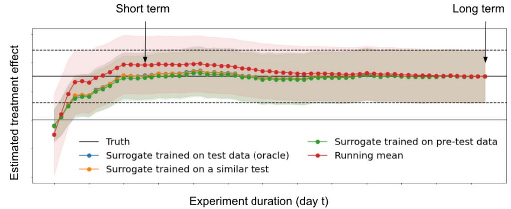
Our first talk was given by Aurelien Bibaut (with co-authors Nathan Kallus, Simon Ejdemyr and Michael Zhao) in which we discussed how to confidently measure long-term outcomes using short term surrogates in the presence of bias. For example, how do we estimate the effects of innovations on retention a year later without running all our experiments for a year? We proposed an estimation method using cross-fold procedures, and construct valid confidence intervals for long term effects before that effect is fully observed.
Later on, Michael Zhao (with Vickie Zhang, Anh Le and Nathan Kallus) spoke about the evaluation of surrogate index models for product decision making. Using 200 real A/B tests performed at Netflix, we showed that surrogate-index models, constructed using only 2 weeks of data, lead to the same product ship decisions ~95% of the time when compared to making a call based on 2 months of data. This means we can reliably run shorter tests with confidence without needing to wait months for results!
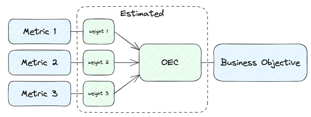
Our next topic focused on how to understand and balance competing engagement metrics; for example, should 1 hour of gaming equal 1 hour of streaming? Michael Zhao and Jordan Schafer shared a poster on how they built an Overall Evaluation Criterion (OEC) metric that provides holistic evaluation for A/B tests, appropriately weighting different engagement metrics to serve a single overall objective. This new framework has enabled fast and confident decision making in tests, and is being actively adapted as our business continues to expand into new areas.
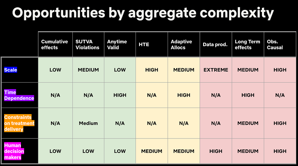
In the second plenary session of the day, Martin Tingley took us on a compelling and fun journey of complexity, exploring key challenges in digital experimentation and how they differ from the challenges faced by agricultural researchers a century ago. He highlighted different areas of complexity and provided perspectives on how to tackle the right challenges based on business objectives.
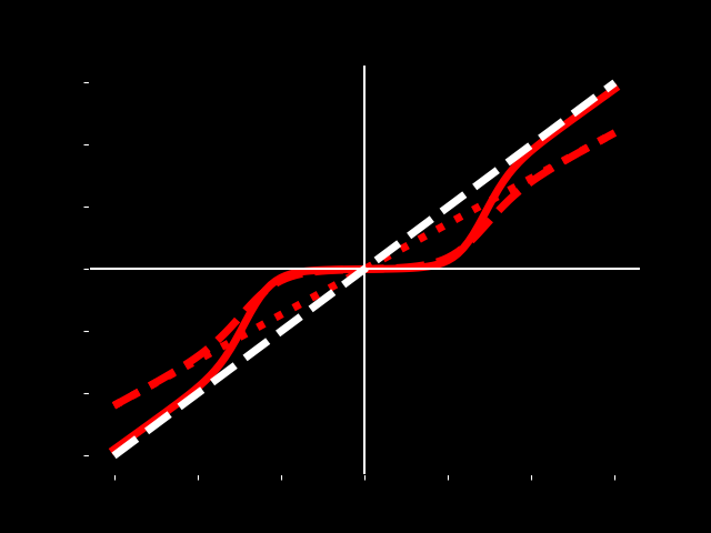
Our final talk was given by Apoorva Lal (with co-authors Samir Khan and Johan Ugander) in which we show how partial identification of the dose-response function (DRF) under non-parametric assumptions can be used to provide more insightful analyses of experimental data than the standard ATE analysis does. We revisited a study that reduced like-minded content algorithmically, and showed how we could extend the binary ATE learning to answer how the amount of like-minded content a user sees affects their political attitudes.
We had a blast connecting with the CODE@MIT community and bonding over our shared enthusiasm for not only rigorous measurement in experimentation, but also stats-themed stickers and swag!
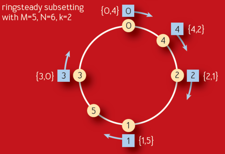
One of our stickers this year, can you guess what this is showing?!
We look forward to next year’s iteration of the conference and hope to see you there!
Psst! We’re hiring Data Scientists across a variety of domains at Netflix — check out our open roles.
At Netflix, we want our viewers to easily find TV shows and movies that resonate and engage. Our creative team helps make this happen by designing promotional artwork that best represents each title featured on our platform. What if we could use machine learning and computer vision to support our creative team in this process? Through identifying the components that contribute to a successful artwork — one that leads a member to choose and watch it — we can give our creative team data-driven insights to incorporate into their creative strategy, and help in their selection of which artwork to feature.
We are going to make an assumption that the presence of a specific component will lead to an artwork’s success. We will discuss a causal framework that will help us find and summarize the successful components as creative insights, and hypothesize and estimate their impact.
The Challenge
Given Netflix’s vast and increasingly diverse catalog, it is a challenge to design experiments that both work within an A/B test framework and are representative of all genres, plots, artists, and more. In the past, we have attempted to design A/B tests where we investigate one aspect of artwork at a time, often within one particular genre. However, this approach has a major drawback: it is not scalable because we either have to label images manually or create new asset variants differing only in the feature under investigation. The manual nature of these tasks means that we cannot test many titles at a time. Furthermore, given the multidimensional nature of artwork, we might be missing many other possible factors that might explain an artwork’s success, such as figure orientation, the color of the background, facial expressions, etc. Since we want to ensure that our testing framework allows for maximum creative freedom, and avoid any interruption to the design process, we decided to try an alternative approach.
Figure. Given the multidimensional nature of artwork, it is challenging to design an A/B test to investigate one aspect of artwork at a given time. We could be missing many other possible factors that might explain an artwork’s success, such as figure orientation, the color of the background, facial expressions, etc.
The Causal Framework
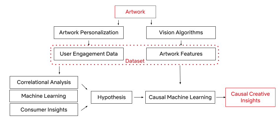
Thanks to our Artwork Personalization System and vision algorithms (some of which are exemplified here), we have a rich dataset of promotional artwork components and user engagement data to build a causal framework. Utilizing this dataset, we have developed the framework to test creative insights and estimate their causal impact on an artwork’s performance via the dataset generated through our recommendation system. In other words, we can learn which attributes led to a title’s successful selection based on its artwork.
Let’s first explore the workflow of the causal framework, as well as the data and success metrics that power it.
We represent the success of an artwork with the take rate: the probability of an average user to watch the promoted title after seeing its promotional artwork, adjusted for the popularity of the title. Every show on our platform has multiple promotional artwork assets. Using Netflix’s Artwork Personalization, we serve these assets to hundreds of millions of members everyday. To power this recommendation system, we look at user engagement patterns and see whether or not these engagements with artworks resulted in a successful title selection.
With the capability to annotate a given image (some of which are mentioned in an earlier post), an artwork asset in this case, we use a series of computer vision algorithms to gather objective image metadata, latent representation of the image, as well as some of the contextual metadata that a given image contains. This process allows our dataset to consist of both the image features and user data, all in an effort to understand which image components lead to successful user engagement. We also utilize machine learning algorithms, consumer insights¹, and correlational analysis for discovering high-level associations between image features and an artwork’s success. These statistically significant associations become our hypotheses for the next phase.
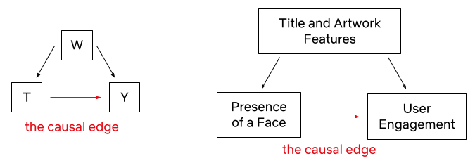
Once we have a specific hypothesis, we can test it by deploying causal machine learning algorithms. This framework reduces our experimental effort to uncover causal relationships, while taking into account confounding among the high-level variables (i.e. the variables that may influence both the treatment / intervention and outcome).
Here are two promotional artwork assets from Unbreakable Kimmy Schmidt. We know that the image on the left performed better than the image on the right. However, the difference between them is not only the presence of a face. There are many other variances, like the difference in background, text placement, font size, face size, etc. Causal Machine Learning makes it possible for us to understand an artwork’s performance based on the causal impact of its treatment.
To make sure our hypothesis is fit for the causal framework, it’s important we go over the identification assumptions.
Consistency: The treatment component is sufficiently well-defined.
We use machine learning algorithms to predict whether or not the artwork contains a face. That’s why the first assumption we make is that our face detection algorithm is mostly accurate (~92% average precision).
Positivity / Probabilistic Assignment: Every unit (an artwork) has some chance of getting treated.
We calculate the propensity score (the probability of receiving the treatment based on certain baseline characteristics) of having a face for samples with different covariates. If a certain subset of artwork (such as artwork from a certain genre) has close to a 0 or 1 propensity score for having a face, then we discard these samples from our analysis.
Individualistic Assignment / SUTVA (stable unit treatment value assumption): The potential outcomes of a unit do not depend on the treatments assigned to others.
Creatives make the decision to create artwork with or without faces based on considerations limited to the title of interest itself. This decision is not dependent on whether other assets have a face in them or not.
Conditional exchangeability (Unconfoundedness): There are no unmeasured confounders.
This assumption is by definition not testable. Given a dataset, we can’t know if there has been an unobserved confounder. However, we can test the sensitivity of our conclusions toward the violation of this assumption in various different ways.
The Models
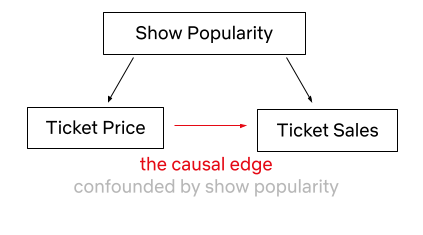
Now that we have established our hypothesis to be a causal inference problem, we can focus on the Causal Machine Learning Application. Predictive Machine Learning (ML) models are great at finding patterns and associations in order to predict outcomes, however they are not great at explaining cause-effect relationships, as their model structure does not reflect causality (the relationship between cause and effect). As an example, let’s say we looked at the price of Broadway theater tickets and the number of tickets sold. An ML algorithm may find a correlation between price increases and ticket sales. If we have used this algorithm for decision making, we could falsely conclude that increasing the ticket price leads to higher ticket sales if we do not consider the confounder of show popularity, which clearly impacts both ticket prices and sales. It is understandable that a Broadway musical ticket may be more expensive if the show is a hit, however simply increasing ticket prices to gain more customers is counter-intuitive.
Causal ML helps us estimate treatment effects from observational data, where it is challenging to conduct clean randomizations. Back-to-back publications on Causal ML, such as Double ML, Causal Forests, Causal Neural Networks, and many more, showcased a toolset for investigating treatment effects, via combining domain knowledge with ML in the learning system. Unlike predictive ML models, Causal ML explicitly controls for confounders, by modeling both treatment of interest as a function of confounders (i.e., propensity scores) as well as the impact of confounders on the outcome of interest. In doing so, Causal ML isolates out the causal impact of treatment on outcome. Moreover, the estimation steps of Causal ML are carefully set up to achieve better error bounds for the estimated treatment effects, another consideration often overlooked in predictive ML. Compared to more traditional Causal Inference methods anchored on linear models, Causal ML leverages the latest ML techniques to not only better control for confounders (when propensity or outcome models are hard to capture by linear models) but also more flexibly estimate treatment effects (when treatment effect heterogeneity is nonlinear). In short, by utilizing machine learning algorithms, Causal ML provides researchers with a framework for understanding causal relationships with flexible ML methods.
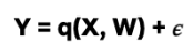
Y : outcome variable (take rate) T : binary treatment variable (presence of a face or not) W: a vector of covariates (features of the title and artwork) X ⊆ W: a vector of covariates (a subset of W) along which treatment effect heterogeneity is evaluated
Let’s dive more into the causal ML (Double ML to be specific) application steps for creative insights.
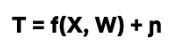
Build a propensity model to predict treatment probability (T) given the W covariates.
2. Build a potential outcome model to predict Y given the W covariates.
3. Residualization of
The treatment (observed T — predicted T via propensity model)
The outcome (observed Y — predicted Y via potential outcome model)
4. Fit a third model on the residuals to predict the average treatment effect (ATE) or conditional average treatment effect (CATE).
Where 𝜖 and η are stochastic errors and we assume that E[ 𝜖|T,W] = 0 , E[ η|W] = 0.
For the estimation of the nuisance functions (i.e., the propensity score model and the outcome model), we have implemented the propensity model as a classifier (as we have a binary treatment variable — the presence of face) and the potential outcome model as a regressor (as we have a continuous outcome variable — adjusted take rate). We have used grid search for tuning the XGBoosting classifier & regressor hyperparameters. We have also used k-fold cross-validation to avoid overfitting. Finally, we have used a causal forest on the residuals of treatment and the outcome variables to capture the ATE, as well as CATE on different genres and countries.
Mediation and Moderation
ATE will reveal the impact of the treatment — in this case, having a face in the artwork — across the board. The result will answer the question of whether it is worth applying this approach for all of our titles across our catalog, regardless of potential conditioning variables e.g. genre, country, etc. Another advantage of our multi-feature dataset is that we get to deep dive into the relationships between attributes. To do this, we can employ two methods: mediation and moderation.
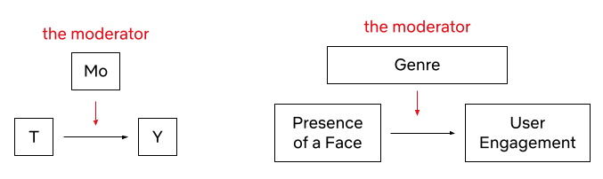
In their classic paper, Baron & Kenny define a moderator as “a qualitative (e.g., sex, race, class) or quantitative (e.g., level of reward) variable that affects the direction and/or strength of the relation between an independent or predictor variable and a dependent or criterion variable.”. We can investigate suspected moderators to uncover Conditional Average Treatment Effects (CATE). For example, we might suspect that the effect of the presence of a face in artwork varies across genres (e.g. certain genres, like nature documentaries, probably benefit less from the presence of a human face since titles in those genres tend to focus more on non-human subject matter). We can investigate these relationships by including an interaction term between the suspected moderator and the independent variable. If the interaction term is significant, we can conclude that the third variable is a moderator of the relationship between the independent and dependent variables.
Mediation, on the other hand, occurs when a third variable explains the relationship between an independent and dependent variable. To quote Baron & Kenny once more, “whereas moderator variables specify when certain effects will hold, mediators speak to how or why such effects occur.”
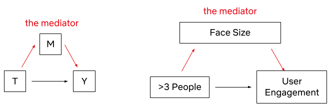
For example, we observed that the presence of more than 3 people tends to negatively impact performance. It could be that higher numbers of faces make it harder for a user to focus on any one face in the asset. However, since face count and face size tend to be negatively correlated (since we fit more information in an image of fixed size, each individual piece of information tends to be smaller), one could also hypothesize that the negative correlation with face count is not driven so much from the number of people featured in the artwork, but rather the size of each individual person’s face, which may affect how visible each person is. To test this, we can run a mediation analysis to see if face size is mediating the effect of face count on the asset’s performance.
The steps of the mediation analysis are as follows: We have already detected a correlation between the independent variable (number of faces) and the outcome variable (user engagement) — in other words, we observed that a higher number of faces is associated with lower user engagement. But, we also observe that the number of faces is negatively correlated with average face size — faces tend to be smaller when more faces are fit into the same fixed-size canvas. To find out the degree to which face size mediates the effect of face count, we regress user engagement on both average face size and the number of faces. If 1) face size is a significant predictor of engagement, and 2) the significance of the predictive contribution of the number of people drops, we can conclude that face size mediates the effect of the number of people in artwork user engagement. If the coefficient for the number of people is no longer significant, it shows that face size fully mediates the effect of the number of faces on engagement.
In this dataset, we found that face size only partially mediates the effect of face count on asset effectiveness. This implies that both factors have an impact on asset effectiveness — fewer faces tend to be more effective even if we control for the effect of face size.
Sensitivity Analysis
As alluded to above, the conditional exchangeability assumption (unconfoundedness) is not testable by definition. It is thus crucial to evaluate how sensitive our findings and insights are to the violation of this assumption. Inspired by prior work, we conducted a suite of sensitivity analyses that stress-tested this assumption from multiple different angles. In addition, we leveraged ideas from academic research (most notably the E-value) and concluded that our estimates are robust even when the unconfoundedness assumption is violated. We are actively working on designing and implementing a standardized framework for sensitivity analysis and will share the various applications in an upcoming blog post — stay tuned for a more detailed discussion!
Finally, we also compared our estimated treatment effects with known effects for specific genres that were derived with other different methods, validating our estimates with consistency across different methods
Conclusion
Using the causal machine learning framework, we can potentially test and identify the various components of promotional artwork and gain invaluable creative insights. With this post, we just started to scratch the surface of this interesting challenge. In the upcoming posts in this series, we will share alternative machine learning and computer vision approaches that can provide insights from a causal perspective. These insights will guide and assist our team of talented strategists and creatives to select and generate the most attractive artwork, leveraging the attributes that these models selected, down to a specific genre. Ultimately this will give Netflix members a better and more personalized experience.
If these types of challenges interest you, please let us know! We are always looking for great people who are inspired by causal inference, machine learning, and computer vision to join our team.
Contributions
The authors contributed to the post as follows.
Billur Engin was the main driver of this blog post, she worked on the causal machine learning theory and its application in the artwork space. Yinghong Lan contributed equally to the causal machine learning theory. Grace Tang worked on the mediation analysis. Cristina Segalin engineered and extracted the visual features at scale from artworks used in the analysis. Grace Tang and Cristina Segalin initiated and conceptualized the problem space that is being used as the illustrative example in this post (studying factors affecting user engagement with a broad multivariate analysis of artwork features), curated the data, and performed initial statistical analysis and construction of predictive models supporting this work.
¹The Consumer Insights team at Netflix seeks to understand members and non-members through a wide range of quantitative and qualitative research methods.
Incremental processing is an approach to process new or changed data in workflows. The key advantage is that it only incrementally processes data that are newly added or updated to a dataset, instead of re-processing the complete dataset. This not only reduces the cost of compute resources but also reduces the execution time in a significant manner. When workflow execution has a shorter duration, chances of failure and manual intervention reduce. It also improves the engineering productivity by simplifying the existing pipelines and unlocking the new patterns.
In this blog post, we talk about the landscape and the challenges in workflows at Netflix. We will show how we are building a clean and efficient incremental processing solution (IPS) by using Netflix Maestro and Apache Iceberg. IPS provides the incremental processing support with data accuracy, data freshness, and backfill for users and addresses many of the challenges in workflows. IPS enables users to continue to use the data processing patterns with minimal changes.
Introduction
Netflix relies on data to power its business in all phases. Whether in analyzing A/B tests, optimizing studio production, training algorithms, investing in content acquisition, detecting security breaches, or optimizing payments, well structured and accurate data is foundational. As our business scales globally, the demand for data is growing and the needs for scalable low latency incremental processing begin to emerge. There are three common issues that the dataset owners usually face.
Data Freshness: Large datasets from Iceberg tables needed to be processed quickly and accurately to generate insights to enable faster product decisions. The hourly processing semantics along with valid–through-timestamp watermark or data signals provided by the Data Platform toolset today satisfies many use cases, but is not the best for low-latency batch processing. Before IPS, the Data Platform did not have a solution for tracking the state and progression of data sets as a single easy to use offering. This has led to a few internal solutions such as Psyberg. These internal libraries process data by capturing the changed partitions, which works only on specific use cases. Additionally, the libraries have tight coupling to the user business logic, which often incurs higher migration costs, maintenance costs, and requires heavy coordination with the Data Platform team.
Data Accuracy: Late arriving data causes datasets processed in the past to become incomplete and as a result inaccurate. To compensate for that, ETL workflows often use a lookback window, based on which they reprocess the data in that certain time window. For example, a job would reprocess aggregates for the past 3 days because it assumes that there would be late arriving data, but data prior to 3 days isn’t worth the cost of reprocessing.
Backfill: Backfilling datasets is a common operation in big data processing. This requires repopulating data for a historical time period which is before the scheduled processing. The need for backfilling could be due to a variety of factors, e.g. (1) upstream data sets got repopulated due to changes in business logic of its data pipeline, (2) business logic was changed in a data pipeline, (3) anew metric was created that needs to be populated for historical time ranges, (4) historical data was found missing, etc.
These challenges are currently addressed in suboptimal and less cost efficient ways by individual local teams to fulfill the needs, such as
Lookback: This is a generic and simple approach that data engineers use to solve the data accuracy problem. Users configure the workflow to read the data in a window (e.g. past 3 hours or 10 days). The window is set based on users’ domain knowledge so that users have a high confidence that the late arriving data will be included or will not matter (i.e. data arrives too late to be useful). It ensures the correctness with a high cost in terms of time and compute resources.
Foreach pattern: Users build backfill workflows using Maestro foreach support. It works well to backfill data produced by a single workflow. If the pipeline has multiple stages or many downstream workflows, users have to manually create backfill workflows for each of them and that requires significant manual work.
The incremental processing solution (IPS) described here has been designed to address the above problems. The design goal is to provide a clean and easy to adopt solution for the Incremental processing to ensure data freshness, data accuracy, and to provide easy backfill support.
Data Freshness: provide the support for scheduling workflows in a micro batch fashion (e.g. 15 min interval) with state tracking functionality
Data Accuracy: provide the support to process all late arriving data to achieve data accuracy needed by the business with significantly improved performance in terms of multifold time and cost efficiency
Backfill: provide managed backfill support to build, monitor, and validate the backfill, including automatically propagating changes from upstream to downstream workflows, to greatly improve engineering productivity (i.e. a few days or weeks of engineering work to build backfill workflows vs one click for managed backfill)
Approach Overview
General Concept
Incremental processing is an approach to process data in batch — but only on new or changed data. To support incremental processing, we need an approach for not only capturing incremental data changes but also tracking their states (i.e. whether a change is processed by a workflow or not). It must be aware of the change and can capture the changes from the source table(s) and then keep tracking those changes. Here, changes mean more than just new data itself. For example, a row in an aggregation target table needs all the rows from the source table associated with the aggregation row. Also, if there are multiple source tables, usually the union of the changed data ranges from all input tables gives the full change data set. Thus, change information captured must include all related data including those unchanged rows in the source table as well. Due to previously mentioned complexities, change tracking cannot be simply achieved by using a single watermark. IPS has to track those captured changes in finer granularity.
The changes from the source tables might affect the transformed result in the target table in various ways.
If one row in the target table is derived from one row in the source table, newly captured data change will be the complete input dataset for the workflow pipeline.
If one row in the target table is derived from multiple rows in the source table, capturing new data will only tell us the rows have to be re-processed. But the dataset needed for ETL is beyond the change data itself. For example, an aggregation based on account id requires all rows from the source table about an account id. The change dataset will tell us which account ids are changed and then the user business logic needs to load all data associated with those account ids found in the change data.
If one row in the target table is derived based on the data beyond the changed data set, e.g. joining source table with other tables, newly captured data is still useful and can indicate a range of data to be affected. Then the workflow will re-process the data based on the range. For example, assuming we have a table that keeps the accumulated view time for a given account partitioned by the day. If the view time 3-days ago is updated right now due to late arriving data, then the view time for the following two days has to be re-calculated for this account. In this case, the captured late arriving data will tell us the start of the re-calculation, which is much more accurate than recomputing everything for the past X days by guesstimate, where X is a cutoff lookback window decided by business domain knowledge.
Once the change information (data or range) is captured, a workflow has to write the data to the target table in a slightly more complicated way because the simple INSERT OVERWRITE mechanism won’t work well. There are two alternatives:
Merge pattern: In some compute frameworks, e.g. Spark 3, it supports MERGE INTO to allow new data to be merged into the existing data set. That solves the write problem for incremental processing. Note that the workflow/step can be safely restarted without worrying about duplicate data being inserted when using MERGE INTO.
Append pattern: Users can also use append only write (e.g. INSERT INTO) to add the new data to the existing data set. Once the processing is completed, the append data is committed to the table. If users want to re-run or re-build the data set, they will run a backfill workflow to completely overwrite the target data set (e.g. INSERT OVERWRITE).
Additionally, the IPS will naturally support the backfill in many cases. Downstream workflows (if there is no business logic change) will be triggered by the data change due to backfill. This enables auto propagation of backfill data in multi-stage pipelines. Note that the backfill support is skipped in this blog. We will talk about IPS backfill support in another following blog post.
Netflix Maestro
Maestro is the Netflix data workflow orchestration platform built to meet the current and future needs of Netflix. It is a general-purpose workflow orchestrator that provides a fully managed workflow-as-a-service (WAAS) to the data platform users at Netflix. It serves thousands of users, including data scientists, data engineers, machine learning engineers, software engineers, content producers, and business analysts, in various use cases. Maestro is highly scalable and extensible to support existing and new use cases and offers enhanced usability to end users.
Since the last blog on Maestro, we have migrated all the workflows to it on behalf of users with minimal interruption. Maestro has been fully deployed in production with 100% workload running on it.
IPS is built upon Maestro as an extension by adding two building blocks, i.e. a new trigger mechanism and step job type, to enable incremental processing for all workflows. It is seamlessly integrated into the whole Maestro ecosystem with minimal onboarding cost.
Apache Iceberg
Iceberg is a high-performance format for huge analytic tables. Iceberg brings the reliability and simplicity of SQL tables to big data, while making it possible for engines like Spark, Trino, Flink, Presto, Hive and Impala to safely work with the same tables, at the same time. It supports expressive SQL, full schema evolution, hidden partitioning, data compaction, and time travel & rollback. In the IPS, we leverage the rich features provided by Apache Iceberg to develop a lightweight approach to capture the table changes.
Incremental Change Capture Design
Using Netflix Maestro and Apache Iceberg, we created a novel solution for incremental processing, which provides the incremental change (data and range) capture in a super lightweight way without copying any data. During our exploration, we see a huge opportunity to improve cost efficiency and engineering productivity using incremental processing.
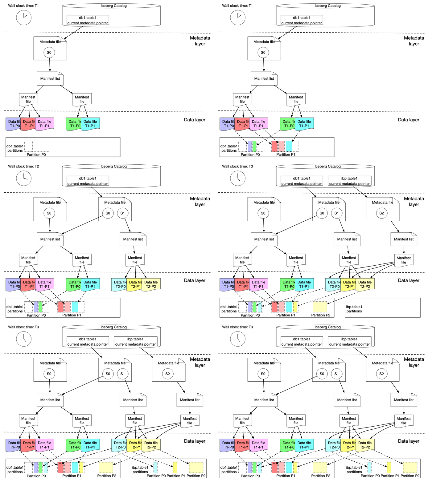
Here is our solution to achieve incremental change capture built upon Apache Iceberg features. As we know, an iceberg table contains a list of snapshots with a set of metadata data. Snapshots include references to the actual immutable data files. A snapshot can contain data files from different partitions.
The graph above shows that s0 contains data for Partition P0 and P1 at T1. Then at T2, a new snapshot s1 is committed to the table with a list of new data files, which includes late arriving data for partition P0 and P1 and data for P2.
We implemented a lightweight approach to create an iceberg table (called ICDC table), which has its own snapshot but only includes the new data file references from the original table without copying the data files. It is highly efficient with a low cost. Then workflow pipelines can just load the ICDC table to process only the change data from partition P0, P1, P2 without reprocessing the unchanged data in P0 and P1. Meanwhile, the change range is also captured for the specified data field as the Iceberg table metadata contains the upper and lower bound information of each data field for each data file. Moreover, IPS will track the changes in data file granularity for each workflow.
This lightweight approach is seamlessly integrated with Maestro to allow all (thousands) scheduler users to use this new building block (i.e. incremental processing) in their tens of thousands of workflows. Each workflow using IPS will be injected with a table parameter, which is the table name of the lightweight ICDC table. The ICDC table contains only the change data. Additionally, if the workflow needs the change range, a list of parameters will be injected to the user workflow to include the change range information. The incremental processing can be enabled by a new step job type (ICDC) and/or a new incremental trigger mechanism. Users can use them together with all existing Maestro features, e.g. foreach patterns, step dependencies based on valid–through-timestamp watermark, write-audit-publish templatized pattern, etc.
Main Advantages
With this design, user workflows can adopt incremental processing with very low efforts. The user business logic is also decoupled from the IPS implementation. Multi-stage pipelines can also mix the incremental processing workflows with existing normal workflows. We also found that user workflows can be simplified after using IPS by removing additional steps to handle the complexity of the lookback window or calling some internal libraries.
Adding incremental processing features into Netflix Maestro as new features/building blocks for users will enable users to build their workflows in a much more efficient way and bridge the gaps to solve many challenging problems (e.g. dealing with late arriving data) in a much simpler way.
Emerging Incremental Processing Patterns
While onboarding user pipelines to IPS, we have discovered a few incremental processing patterns:
Incrementally process the captured incremental change data and directly append them to the target table
This is the straightforward incremental processing use case, where the change data carries all the information needed for the data processing. Upstream changes (usually from a single source table) are propagated to the downstream (usually another target table) and the workflow pipeline only needs to process the change data (might join with other dimension tables) and then merge into (usually append) to the target table. This pattern will replace lookback window patterns to take care of late arriving data. Instead of overwriting past X days of data completely by using a lookback window pattern, user workflows just need to MERGE the change data (including late arriving data) into the target table by processing the ICDC table.
Use captured incremental change data as the row level filter list to remove unnecessary transformation
ETL jobs usually need to aggregate data based on certain group-by keys. Change data will disclose all the group-by keys that require a re-aggregation due to the new landing data from the source table(s). Then ETL jobs can join the original source table with the ICDC table on those group-by keys by using ICDC as a filter to speed up the processing to enable calculations of a much smaller set of data. There is no change to business transform logic and no re-design of ETL workflow. ETL pipelines keep all the benefits of batch workflows.
Use the captured range parameters in the business logic
This pattern is usually used in complicated use cases, such as joining multiple tables and doing complex processings. In this case, the change data do not give the full picture of the input needed by the ETL workflow. Instead, the change data indicates a range of changed data sets for a specific set of fields (might be partition keys) in a given input table or usually multiple input tables. Then, the union of the change ranges from all input tables gives the full change data set needed by the workflow. Additionally, the whole range of data usually has to be overwritten because the transformation is not stateless and depends on the outcome result from the previous ranges. Another example is that the aggregated record in the target table or window function in the query has to be updated based on the whole data set in the partition (e.g. calculating a medium across the whole partition). Basically, the range derived from the change data indicates the dataset to be re-processed.
Use cases
Data workflows at Netflix usually have to deal with late arriving data which is commonly solved by using lookback window pattern due to its simplicity and ease of implementation. In the lookback pattern, the ETL pipeline will always consume the past X number of partition data from the source table and then overwrite the target table in every run. Here, X is a number decided by the pipeline owners based on their domain expertise. The drawback is the cost of computation and execution time. It usually costs almost X times more than the pipeline without considering late arriving data. Given the fact that the late arriving data is sparse, the majority of the processing is done on the data that have been already processed, which is unnecessary. Also, note that this approach is based on domain knowledge and sometimes is subject to changes of the business environment or the domain expertise of data engineers. In certain cases, it is challenging to come up with a good constant number.
Below, we will use a two-stage data pipeline to illustrate how to rebuild it using IPS to improve the cost efficiency. We will observe a significant cost reduction (> 80%) with little changes in the business logic. In this use case, we will set the lookback window size X to be 14 days, which varies in different real pipelines.
Original Data Pipeline with Lookback Window
playback_table: an iceberg table holding playback events from user devices ingested by streaming pipelines with late arriving data, which is sparse, only about few percents of the data is late arriving.
playback_daily_workflow: a daily scheduled workflow to process the past X days playback_table data and write the transformed data to the target table for the past X days
playback_daily_table: the target table of the playback_daily_workflow and get overwritten every day for the past X days
playback_daily_agg_workflow: a daily scheduled workflow to process the past X days’ playback_daily_table data and write the aggregated data to the target table for the past X days
playback_daily_agg_table: the target table of the playback_daily_agg_workflow and get overwritten every day for the past 14 days.
We ran this pipeline in a sample dataset using the real business logic and here is the average execution result of sample runs
The first stage workflow takes about 7 hours to process playback_table data
The second stage workflow takes about 3.5 hours to process playback_daily_table data
New Data Pipeline with Incremental Processing
Using IPS, we rewrite the pipeline to avoid re-processing data as much as possible. The new pipeline is shown below.
Stage 1:
ips_playback_daily_workflow: it is the updated version of playback_daily_workflow.
The workflow spark sql job then reads an incremental change data capture (ICDC) iceberg table (i.e. playback_icdc_table), which only includes the new data added into the playback_table. It includes the late arriving data but does not include any unchanged data from playback_table.
The business logic will replace INSERT OVERWRITE by MERGE INTO SQL query and then the new data will be merged into the playback_daily_table.
Stage 2:
IPS captures the changed data of playback_daily_table and also keeps the change data in an ICDC source table (playback_daily_icdc_table). So we don’t need to hard code the lookback window in the business logic. If there are only Y days having changed data in playback_daily_table, then it only needs to load data for Y days.
In ips_playback_daily_agg_workflow, the business logic will be the same for the current day’s partition. We then need to update business logic to take care of late arriving data by
JOIN the playback_daily table with playback_daily_icdc_table on the aggregation group-by keys for the past 2 to X days, excluding the current day (i.e. day 1)
Because late arriving data is sparse, JOIN will narrow down the playback_daily_table data set so as to only process a very small portion of it.
The business logic will use MERGE INTO SQL query then the change will be propagated to the downstream target table
For the current day, the business logic will be the same and consume the data from playback_daily_table and then write the outcome to the target table playback_daily_agg_table using INSERT OVERWRITE because there is no need to join with the ICDC table.
With these small changes, the data pipeline efficiency is greatly improved. In our sample run,
The first stage workflow takes just about 30 minutes to process X day change data from playback_table.
The second stage workflow takes about 15 minutes to process change data between day 2 to day X from playback_daily_table by joining with playback_daily_cdc_table data and takes another 15 minutes to process the current day (i.e. day 1) playback_daily_table change data.
Here the spark job settings are the same in original and new pipelines. So in total, the new IPS based pipeline overall needs around 10% of resources (measured by the execution time) to finish.
Looking Forward
We will improve IPS to support more complicated cases beyond append-only cases. IPS will be able to keep track of the progress of the table changes and support multiple Iceberg table change types (e.g. append, overwrite, etc.). We will also add managed backfill support into IPS to help users to build, monitor, and validate the backfill.
We are taking Big Data Orchestration to the next level and constantly solving new problems and challenges, please stay tuned. If you are motivated to solve large scale orchestration problems, please join us.
Acknowledgements
Thanks to our Product Manager Ashim Pokharel for driving the strategy and requirements. We’d also like to thank Andy Chu, Kyoko Shimada, Abhinaya Shetty, Bharath Mummadisetty, John Zhuge, Rakesh Veeramacheneni, and other stunning colleagues at Netflix for their suggestions and feedback while developing IPS. We’d also like to thank Prashanth Ramdas, Eva Tse, Charles Smith, and other leaders of Netflix engineering organizations for their constructive feedback and suggestions on the IPS architecture and design.
This blog post will cover how Psyberg helps automate the end-to-end catchup of different pipelines, including dimension tables.
In the previous installments of this series, we introduced Psyberg and delved into its core operational modes: Stateless and Stateful Data Processing. Now, let’s explore the state of our pipelines after incorporating Psyberg.
Pipelines After Psyberg
Let’s explore how different modes of Psyberg could help with a multistep data pipeline. We’ll return to the sample customer lifecycle:
Processing Requirement: Keep track of the end-of-hour state of accounts, e.g., Active/Upgraded/Downgraded/Canceled.
Solution: One potential approach here would be as follows
Create two statelessfact tables : a. Signups b. Account Plans
Create one statefulfact table: a. Cancels
Create a stateful dimension that reads the above fact tables every hour and derives the latest account state.
Let’s look at how this can be integrated with Psyberg to auto-handle late-arriving data and corresponding end-to-end data catchup.
Navigating the Workflow: How Psyberg Handles Late-Arriving Data
We follow a generic workflow structure for both stateful and stateless processing with Psyberg; this helps maintain consistency and makes debugging and understanding these pipelines easier. The following is a concise overview of the various stages involved; for a more detailed exploration of the workflow specifics, please turn to the second installment of this series.
1. Psyberg Initialization
The workflow starts with the Psyberg initialization (init) step.
Input: List of source tables and required processing mode
Output: Psyberg identifies new events that have occurred since the last high watermark (HWM) and records them in the session metadata table.
The session metadata table can then be read to determine the pipeline input.
2. Write-Audit-Publish (WAP) Process
This is the general pattern we use in our ETL pipelines.
a. Write Apply the ETL business logic to the input data identified in Step 1 and write to an unpublished iceberg snapshot based on the Psyberg mode
b. Audit Run various quality checks on the staged data. Psyberg’s metadata session table is used to identify the partitions included in a batch run. Several audits, such as verifying source and target counts, are performed on this batch of data.
c. Publish If the audits are successful, cherry-pick the staging snapshot to publish the data to production.
3. Psyberg Commit
Now that the data pipeline has been executed successfully, the new high watermark identified in the initialization step is committed to Psyberg’s high watermark metadata table. This ensures that the next instance of the workflow will pick up newer updates.
Callouts
Having the Psyberg step isolated from the core data pipeline allows us to maintain a consistent pattern that can be applied across stateless and stateful processing pipelines with varying requirements.
This also enables us to update the Psyberg layer without touching the workflows.
This is compatible with both Python and Scala Spark.
Debugging/figuring out what was loaded in every run is made easy with the help of workflow parameters and Psyberg Metadata.
The Setup: Automated end-to-end catchup
Let’s go back to our customer lifecycle example. Once we integrate all four components with Psyberg, here’s how we would set it up for automated catchup.
The three fact tables, comprising the signup and plan facts encapsulated in Psyberg’s stateless mode, along with the cancel fact in stateful mode, serve as inputs for the stateful sequential load ETL pipeline. This data pipeline monitors the various stages in the customer lifecycle.
In the sequential load ETL, we have the following features:
Catchup Threshold: This defines the lookback period for the data being read. For instance, only consider the last 12 hours of data.
Data Load Type: The ETL can either load the missed/new data specifically or reload the entire specified range.
Metadata Recording: Metadata is persisted for traceability.
Here is a walkthrough on how this system would automatically catch up in the event of late-arriving data:
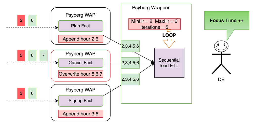
Premise: All the tables were last loaded up to hour 5, meaning that any data from hour 6 onwards is considered new, and anything before that is classified as late data (as indicated in red above)
Fact level catchup:
During the Psyberg initialization phase, the signup and plan facts identify the late data from hours 2 and 3, as well as the most recent data from hour 6. The ETL then appends this data to the corresponding partitions within the fact tables.
The Psyberg initialization for the cancel fact identifies late data from hour 5 and additional data from hours 6 and 7. Since this ETL operates in stateful mode, the data in the target table from hours 5 to 7 will be overwritten with the new data.
By focusing solely on updates and avoiding reprocessing of data based on a fixed lookback window, both Stateless and Stateful Data Processing maintain a minimal change footprint. This approach ensures data processing is both efficient and accurate.
Dimension level catchup:
The Psyberg wrapper for this stateful ETL looks at the updates to the upstream Psyberg powered fact tables to determine the date-hour range to reprocess. Here’s how it would calculate the above range: MinHr = least(min processing hour from each source table) This ensures that we don’t miss out on any data, including late-arriving data. In this case, the minimum hour to process the data is hour 2. MaxHr = least(max processing hour from each source table) This ensures we do not process partial data, i.e., hours for which data has not been loaded into all source tables. In this case, the maximum hour to process the data is hour 6.
The ETL process uses this time range to compute the state in the changed partitions and overwrite them in the target table. This helps overwrite data only when required and minimizes unnecessary reprocessing.
As seen above, by chaining these Psyberg workflows, we could automate the catchup for late-arriving data from hours 2 and 6. The Data Engineer does not need to perform any manual intervention in this case and can thus focus on more important things!
The Impact: How Psyberg Transformed Our Workflows
The introduction of Psyberg into our workflows has served as a valuable tool in enhancing accuracy and performance. The following are key areas that have seen improvements from using Psyberg:
Computational Resources Used: In certain instances, we’ve noticed a significant reduction in resource utilization, with the number of Spark cores used dropping by 90% following the implementation of Psyberg, compared to using fixed lookback windows
Workflow and Table Onboarding: We have onboarded 30 tables and 13 workflows into incremental processing since implementing Psyberg
Reliability and Accuracy: Since onboarding workflows to Psyberg, we have experienced zero manual catchups or missing data incidents
Bootstrap template: The process of integrating new tables into incremental processing has been made more accessible and now requires minimal effort using Psyberg
These performance metrics suggest that adopting Psyberg has been beneficial to the efficiency of our data processing workflows.
Next Steps and Conclusion
Integrating Psyberg into our operations has improved our data workflows and opened up exciting possibilities for the future. As we continue to innovate, Netflix’s data platform team is focused on creating a comprehensive solution for incremental processing use cases. This platform-level solution is intended to enhance our data processing capabilities across the organization. Stay tuned for a new post on this!
In conclusion, Psyberg has proven to be a reliable and effective solution for our data processing needs. As we look to the future, we’re excited about the potential for further advancements in our data platform capabilities.
In the inaugural blog post of this series, we introduced you to the state of our pipelines before Psyberg and the challenges with incremental processing that led us to create the Psyberg framework within Netflix’s Membership and Finance data engineering team. In this post, we will delve into a more detailed exploration of Psyberg’s two primary operational modes: stateless and stateful.
Modes of Operation of Psyberg
Psyberg has two main modes of operation or patterns, as we call them. Understanding the nature of the late-arriving data and processing requirements will help decide which pattern is most appropriate for a use case.
Stateless Data Processing: As the name suggests, one should use this pattern in scenarios where the columns in the target table solely depend on the content of the incoming events, irrespective of their order of occurrence. For instance, consider a scenario where we need to keep track of all the customer signups over time. In this case, the order of signups wouldn’t matter, and individual signup records are independent of each other. This information has only one source, and we can append new/late records to the fact table as and when the events are received.
Stateful Data Processing: This pattern is useful when the output depends on a sequence of events across one or more input streams. For example, the customer account lifecycle in a business might involve multiple stages, such as account creation, plan upgrades, downgrades, and cancellation. To derive attributes like the lifetime of an account or the latest plan the account is on, we need to track the sequence of these events across different input streams. A missed event in such a scenario would result in incorrect analysis due to a wrong derived state. Late-arriving data in such cases requires overwriting data that was previously processed to ensure all events are accounted for.
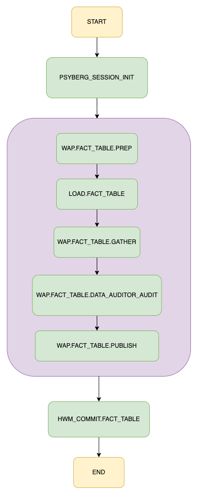
Let’s visualize how these two modes work within our data processing pipeline using a general workflow for loading a fact table. If you would like to learn more about how the workflows are orchestrated in Netflix Maestro scheduler, please check out this blog post from our data platform team.
With this illustration as our guide, let’s explore each mode in more detail.
The Psyberg Initialization Phase
This step invokes Psyberg with the required parameters. Based on these parameters, Psyberg then computes the correct data range for the pipeline processing needs.
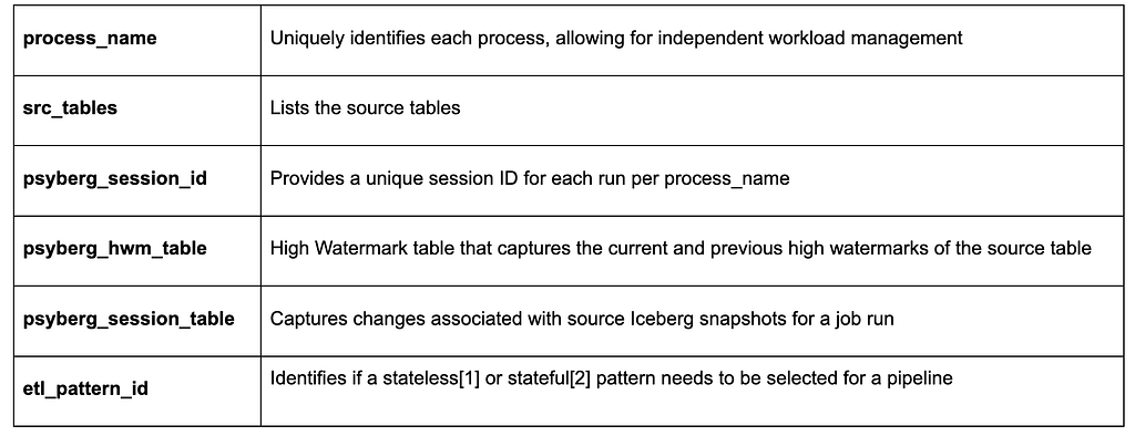
Input parameters in this step include the following:
Initialization for Stateless Data Processing
Let’s use the signup fact table as an example here. This table’s workflow runs hourly, with the main input source being an Iceberg table storing all raw signup events partitioned by landing date, hour, and batch id.
Here’s a YAML snippet outlining the configuration for this during the Psyberg initialization step:
Behind the scenes, Psyberg identifies that this pipeline is configured for a stateless pattern since etl_pattern_id=1.
Psyberg also uses the provided inputs to detect the Iceberg snapshots that persisted after the latest high watermark available in the watermark table. Using the summary column in snapshot metadata [see the Iceberg Metadata section in post 1 for more details], we parse out the partition information for each Iceberg snapshot of the source table.
Psyberg then retains these processing URIs (an array of JSON strings containing combinations of landing date, hour, and batch IDs) as determined by the snapshot changes. This information and other calculated metadata are stored in the psyberg_session_f table. This stored data is then available for the subsequent LOAD.FACT_TABLE job in the workflow to utilize and for analysis and debugging purposes.
Initialization for Stateful Data Processing
Stateful Data Processing is used when the output depends on a sequence of events across one or more input streams.
Let’s consider the example of creating a cancel fact table, which takes the following as input:
Raw cancellation events indicating when the customer account was canceled
A fact table that stores incoming customer requests to cancel their subscription at the end of the billing period
These inputs help derive additional stateful analytical attributes like the type of churn i.e. voluntary or involuntary, etc.
The initialization step for Stateful Data Processing differs slightly from Stateless. Psyberg offers additional configurations according to the pipeline needs. Here’s a YAML snippet outlining the configuration for the cancel fact table during the Psyberg initialization step:
Behind the scenes, Psyberg identifies that this pipeline is configured for a stateful pattern since etl_pattern_id is 2.
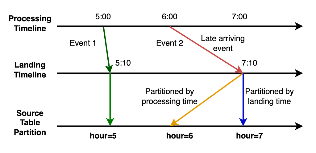
Notice the additional detail in the src_tables list corresponding to raw_cancels above. The processing_ts here represents the event processing timestamp which is different from the regular Iceberg snapshot commit timestamp i.e. event_landing_ts as described in part 1 of this series.
It is important to capture the range of a consolidated batch of events from all the sources i.e. both raw_cancels and cancel_request_fact, while factoring in late-arriving events. Changes to the source table snapshots can be tracked using different timestamp fields. Knowing which timestamp field to use i.e. event_landing_ts or something like processing_ts helps avoid missing events.
Similar to the approach in stateless data processing, Psyberg uses the provided inputs to parse out the partition information for each Iceberg snapshot of the source table.
Sample parsed input for target snapshot_date 20230914 and snapshot_hour 9
This is then used to query the partitions metadata table which has the min and max range for each column in the source table. In this case, we look at the min and max range of the processing_ts column to determine actual partitions for any late-arriving events. The minimum value here helps determine the lower limit of the data to be processed i.e. the derived minimum date and hour based on the input epoch timestamp.
Lower Limit to be processed = least ( “min” event_processing_ts)
It also tracks the VTTS (Valid To TimeStamp) of all the input streams and determines the minimum VTTS of all the streams together. This helps determine the upper limit of data to be processed, thus restricting the data load based on data completeness of all the streams combined.
Upper Limit to be processed = least (vtts date-hour)
Using this metadata from different streams, Psyberg calculates several parameters like minimum/maximum processing date and hour and event landing date hour. These parameters, along with other metadata, discussed in the previous post, are persisted in the psyberg_session_f table for analysis and debugging purposes.
Write Audit Publish (WAP) process
The Write Audit Publish (WAP) process is a general pattern we use in our ETLs to validate writes to the uncommitted Iceberg snapshot before publishing to the target table. The LOAD.FACT_TABLE step takes psyberg_session_id and process_name as input arguments.
For stateless pattern, the processing URIs to be processed as part of the load step are identified by reading the psyberg_session_f table. This information is then used to filter the source table and apply the business logic to create the signup fact table. Any late-arriving signup events data is appended to the target table partitions as part of this. All these writes go into the uncommitted Iceberg snapshot managed by the WAP pattern.
Similarly, in the stateful pattern, the ETL step reads the psyberg_session_f table to identify the derived minimum and maximum date hour range to be processed, which acts as a filter for different input tables involved in the ETL. After applying the corresponding business logic for cancellation events, we create the cancel fact table along with columns like cancellation type (i.e., voluntary vs involuntary churn) representing the state of the canceled account. If there are any late-arriving events, Psyberg handles them automatically by providing the correct range to the data process to derive the state changes correctly.
Audits
We run different audits on the uncommitted Iceberg snapshot created as part of the job run. Leveraging Psyberg metadata, we can identify the cohort of data involved as part of the job run. This helps in pinpointing changes and applying blocking audits efficiently. Audits like source-to-target count comparison and checking for no missing events in the target Iceberg snapshot ensure data integrity and completeness. Once the audits pass successfully, the data is published to the target table.
HWM Commit
Leveraging Psyberg metadata tables, we determine the latest timestamp associated with the Iceberg snapshot seen as part of the job run. This timestamp is used to update the high watermark table with the new high watermark so that the subsequent pipeline instance can pick up the next set of changes.
Conclusion
This exploration shows how Psyberg brings efficiency, accuracy, and timeliness to Stateless and Stateful Data Processing within the Membership and Finance data engineering team. Join us in the next part of our blog series, where we’ll discuss how it also helps automate the end-to-end catchup of different pipelines.
At Netflix, our Membership and Finance Data Engineering team harnesses diverse data related to plans, pricing, membership life cycle, and revenue to fuel analytics, power various dashboards, and make data-informed decisions. Many metrics inNetflix’s financial reports are powered and reconciled with efforts from our team! Given our role on this critical path, accuracy is paramount. In this context, managing the data, especially when it arrives late, can present a substantial challenge!
In this three-part blog post series, we introduce you to Psyberg, our incremental data processing framework designed to tackle such challenges! We’ll discuss batch data processing, the limitations we faced, and how Psyberg emerged as a solution. Furthermore, we’ll delve into the inner workings of Psyberg, its unique features, and how it integrates into our data pipelining workflows. By the end of this series, we hope you will gain an understanding of how Psyberg transformed our data processing, making our pipelines more efficient, accurate, and timely. Let’s dive in!
The Challenge: Incremental Data Processing with Late Arriving Data
Our teams’ data processing model mainly comprises batch pipelines, which run at different intervals ranging from hourly to multiple times a day (also known as intraday) and even daily. We expect complete and accurate data at the end of each run. To meet such expectations, we generally run our pipelines with a lag of a few hours to leave room for late-arriving data.
What is late-arriving data?
Late-arriving data is essentially delayed data due to system retries, network delays, batch processing schedules, system outages, delayed upstream workflows, or reconciliation in source systems.
How does late-arriving data impact us?
You could think of our data as a puzzle. With each new piece of data, we must fit it into the larger picture and ensure it’s accurate and complete. Thus, we must reprocess the missed data to ensure data completeness and accuracy.
Types of late-arriving data
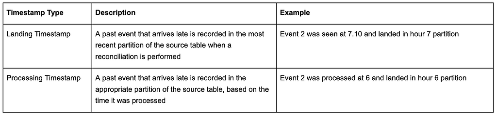
Based on the structure of our upstream systems, we’ve classified late-arriving data into two categories, each named after the timestamps of the updated partition:
Ways to process such data
Our team previously employed some strategies to manage these scenarios, which often led to unnecessarily reprocessing unchanged data. Some techniques we used were:
1. Using fixed lookback windows to always reprocess data, assuming that most late-arriving events will occur within that window. However, this approach usually leads to redundant data reprocessing, thereby increasing ETL processing time and compute costs. It also becomes inefficient as the data scale increases. Imagine reprocessing the past 6 hours of data every hour!
2. Add alerts to flag when late arriving data appears, block the pipelines, and perform a manual intervention where we triggered backfill pipelines to handle the missed events. This approach was a simple solution with minimal extra processing for the most part and, hence, was our preferred solution. However, when the late events occurred, the pain of reprocessing data and catching up on all the dependent pipelines was not worth it! We will talk about this shortly.
At a high level, both these approaches were inefficient for intraday pipelines and impacted cost, performance, accuracy, and time. We developed Psyberg, an incremental processing framework using Iceberg to handle these challenges more effectively.
The state of our pipelines before Psyberg
Before diving into the world of Psyberg, it’s crucial to take a step back and reflect on the state of the data pipelines in our team before its implementation. The complexities involved in these processes and the difficulties they posed led to the development of Psyberg.
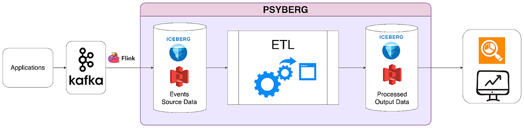
At Netflix, our backend microservices continuously generate real-time event data that gets streamed into Kafka. These raw events are the source of various data processing workflows within our team. We ingest this diverse event data and transform it into standardized fact tables. The fact tables then feed downstream intraday pipelines that process the data hourly. The sequential load ETL shown in the diagram below depicts one such pipeline that calculates an account's state every hour.
Raw data for hours 3 and 6 arrive. Hour 6 data flows through the various workflows, while hour 3 triggers a late data audit alert.
Let’s walk through an example to understand the complexity of this pre-Psyberg world.
Consider a simplified version of our pipelines where we process three events: signups, plan changes, and cancels. Now imagine that some signup events from hour 3 were delayed and sent in at hour 6 instead. Our audits would detect this and alert the on-call data engineer (DE). The on-call DE would then face the daunting task of making things right!
Step 1: Dive into the audit logs to identify the late-arriving data and the impacted workflows. In this case, they would discover that the late-arriving data for hour 3 must be included in the signup facts.
Step 2: Stop all impacted workflows and downstream jobs (such as the sequential load ETL) and patch the missed data in the fact tables. Now, the data in the signup fact is patched.
Step 3: Identify the number of partitions to be rerun for the sequential stateful load jobs to account for the delayed data and rerun them from the impacted date-hour. The DE would note that the data for hours 3–6 needs to be reprocessed and will retrigger four instances to be run sequentially. This step is crucial because missing signup events from hour 3 would result in us missing subsequent events for those affected accounts (e.g., a cancel event for a missed signup would have had no effect). As we capture the state of an account based on the sequence of different types of events, rerunning the sequential load ETL from hours 3 to 6 ensures the accurate representation of account states.
Step 4: Now that we’ve spent significant time triaging and resolving the alert, the sequential ETL workflow likely experienced a delay. As a result, we need to catch up to schedule. To compensate for the lost time, the DE must trigger a few additional instances until the latest hour that would have run if the data hadn’t arrived late.
This entire process was challenging and required significant manual intervention from the on-call DE perspective. Note that these are hourly jobs, so the alert could be triggered at any time of the day (or night!). Yes, they were infrequent, but a big pain point when they occurred! Also, the on-call DE was usually not the SME for these pipelines, as the late data could have arrived in any of our upstream pipelines. To solve these problems, we came up with Psyberg!
Psyberg: The Game Changer!
Psyberg automates our data loads, making it suitable for various data processing needs, including intraday pipeline use cases. It leverages Iceberg metadata to facilitate processing incremental and batch-based data pipelines.
One of the critical features of Psyberg is its ability to detect and manage late-arriving data, no matter the partition it lands in. This feature allows data pipelines to handle late-arriving data effectively without manual intervention, ensuring higher data accuracy in our systems. Iceberg metadata and Psyberg’s own metadata form the backbone of its efficient data processing capabilities.
ETL Process High Watermark
This is the last recorded update timestamp for any data pipeline process. This is mainly used to identify new changes since the last update.
Iceberg Metadata
Psyberg primarily harnesses two key iceberg metadata tables — snapshots and partitions — to manage the workload. All Iceberg tables have associated metadata that provide insight into changes or updates within the data tables.
The snapshots metadata table records essential metadata such as:
The creation time of a snapshot
The type of operation performed (append, overwrite, etc.)
A summary of partitions created/updated during the generation of the Iceberg snapshot
These details enable Psyberg to track different operations and identify changes made to a source table since the previous high watermark. For example:
The partitions metadata table is particularly interesting as it stores:
Information about partition keys used in the data table
Column names and the range of values for each column within a specific partition
One unique aspect of Netflix’s internal implementation is that it provides the range of values for each column within a partition in a deserialized format. This information helps Psyberg comprehend the timestamp ranges for both types of late-arriving data (event and processing time) without querying the actual data.
Psyberg Metadata
In addition to Iceberg metadata, Psyberg maintains its own metadata tables — the session table and the high watermark table. Both these tables are partitioned by the pipeline process name to maintain information related to each data pipeline independently.
The session table captures metadata specific to each pipeline run, including:
Process name partition to track all the runs associated with the data pipeline process
Session ID to track unique runs within the process
Processing URIs to identify the input partitions involved in the load
“from date”, “from hour”, “to date” and “to hour” for both event and processing times
The high watermark table stores relevant values from the session table at the end of each pipeline run:
Latest and previous high water mark timestamp
Metadata related to the latest run
This information is vital for each pipeline run instance as it helps determine the data to be loaded, updates the high water mark after processing, and finally generates output signals to inform downstream workflows about the date-hour up to which data is complete and available. It also serves as an essential resource for debugging and creating audits on the pipeline jobs.
Conclusion
In this post, we described our data architecture at a high level, along with the pain points that led to the development of Psyberg. We also went into details related to the metadata that powers Psyberg. If you understand the challenges faced by the on-call DE and would like to learn more about our solution, please check out the next iteration of this three-part series, where we delve deeper into different modes of Psyberg.
When you enjoy the latest season of Stranger Things or Casa de Papel (Money Heist), have you ever wondered about the secrets to fantastic story-telling, besides the stunning visual presentation? From the violin melody accompanying a pivotal scene to the soaring orchestral arrangement and thunderous sound-effects propelling an edge-of-your-seat action sequence, the various components of the audio soundtrack combine to evoke the very essence of story-telling. To uncover the magic of audio soundtracks and further improve the sonic experience, we need a way to systematically examine the interaction of these components, typically categorized as dialogue, music and effects.
In this blog post, we will introduce speech and music detection as an enabling technology for a variety of audio applications in Film & TV, as well as introduce our speech and music activity detection (SMAD) system which we recently published as a journal article in EURASIP Journal on Audio, Speech, and Music Processing.
Like semantic segmentation for audio, SMAD separately tracks the amount of speech and music in each frame in an audio file and is useful in content understanding tasks during the audio production and delivery lifecycle. The detailed temporal metadata SMAD provides about speech and music regions in a polyphonic audio mixture are a first step for structural audio segmentation, indexing and pre-processing audio for the following downstream tasks. Let’s have a look at a few applications.
Practical use cases for speech & music activity
Audio dataset preparation
Speech & music activity is an important preprocessing step to prepare corpora for training. SMAD classifies & segments long-form audio for use in large corpora, such as
utterances for speech tasks like speaker diarization, emotion classification, semantic and phonetic transcription and translation.
From “Audio Signal Classification” by David Gerhard
Dialogue analysis & processing
During encoding at Netflix, speech-gated loudness is computed for every audio master track and used for loudness normalization. Speech-activity metadata is thus a central part of accurate catalog-wide loudness management and improved audio volume experience for Netflix members.
Similarly, algorithms for dialogue intelligibility, spoken-language-identification and speech-transcription are only applied to audio regions where there is measured speech.
Music information retrieval
There are a few studio use cases where music activity metadata is important, including quality-control (QC) and at-scale multimedia content analysis and tagging.
There are also inter-domain tasks like singer-identification and song lyrics transcription, which do not fit neatly into either speech or classical MIR tasks, but are useful for annotating musical passages with lyrics in closed captions and subtitles.
Conversely, where neither speech nor music activity is present, such audio regions are estimated to have content classified as noisy, environmental or sound-effects.
Localization & Dubbing
Finally, there are post-production tasks, which take advantage of accurate speech segmentation at the the spoken utterance or sentence level, ahead of translation and dub-script generation. Likewise, authoring accessibility-features like Audio Description (AD) involves music and speech segmentation. The AD narration is typically mixed-in to not overlap with the primary dialogue, while music lyrics strongly tied to the plot of the story, are sometimes referenced by AD creators, especially for translated AD.
A voice actor in the studio
Our Approach to Speech and Music Activity Detection
Although the application of deep learning methods has improved audio classification systems in recent years, this data driven approach for SMAD requires large amounts of audio source material with audio-frame level speech and music activity labels. The collection of such fine-resolution labels is costly and labor intensive and audio content often cannot be publicly shared due to the copyright limitations. We address the challenge from a different angle.
Content, genre and languages
Instead of augmenting or synthesizing training data, we sample the large scale data available in the Netflix catalog with noisy labels. In contrast to clean labels, which indicate precise start and end times for each speech/music region, noisy labels only provide approximate timing, which may impact SMAD classification performance. Nevertheless, noisy labels allow us to increase the scale of the dataset with minimal manual efforts and potentially generalize better across different types of content.
Our dataset, which we introduced as TVSM (TV Speech and Music) in our publication, has a total number of 1608 hours of professionally recorded and produced audio. TVSM is significantly larger than other SMAD datasets and contains both speech and music labels at the frame level. TVSM also contains overlapping music and speech labels, and both classes have a similar total duration.
Training examples were produced between 2016 and 2019, in 13 countries, with 60% of the titles originating in the USA. Content duration ranged from 10 minutes to over 1 hour, across the various genres listed below.
The dataset contains audio tracks in three different languages, namely English, Spanish, and Japanese. The language distribution is shown in the figure below. The name of the episode/TV show for each sample remains unpublished. However, each sample has both a show-ID and a season-ID to help identify the connection between the samples. For instance, two samples from different seasons of the same show would share the same show ID and have different season IDs.
What constitutes music or speech?
To evaluate and benchmark our dataset, we manually labeled 20 audio tracks from various TV shows which do not overlap with our training data. One of the fundamental issues encountered during the annotation of our manually-labeled TVSM-test set, was the definition of music and speech. The heavy usage of ambient sounds and sound effects blurs the boundaries between active music regions and non-music. Similarly, switches between conversational speech and singing voices in certain TV genres obscure where speech starts and music stops. Furthermore, must these two classes be mutually exclusive? To ensure label quality, consistency, and to avoid ambiguity, we converged on the following guidelines for differentiating music and speech:
Any music that is perceivable by the annotator at a comfortable playback volume should be annotated.
Since sung lyrics are often included in closed-captions or subtitles, human singing voices should all be annotated as both speech and music.
Ambient sound or sound effects without apparent melodic contours should not be annotated as music. Traditional phone bell, ringing, or buzzing without apparent melodic contours should not be annotated as music.
Filled pauses (uh, um, ah, er), backchannels (mhm, uh-huh), sighing, and screaming should not be annotated as speech.
Audio format and preprocessing
All audio files were originally delivered from the post-production studios in the standard 5.1 surround format at 48 kHz sampling rate. We first normalize all files to an average loudness of −27 LKFS ± 2 LU dialog-gated, then downsample to 16 kHz before creating an ITU downmix.
Model Architecture
Our modeling choices take advantage of both convolutional and recurrent architectures, which are known to work well on audio sequence classification tasks, and are well supported by previous investigations. We adapted the SOTA convolutional recurrent neural network (CRNN) architecture to accommodate our requirements for input/output dimensionality and model complexity. The best model was a CRNN with three convolutional layers, followed by two bi-directional recurrent layers and one fully connected layer. The model has 832k trainable parameters and emits frame-level predictions for both speech and music with a temporal resolution of 5 frames per second.
For training, we leveraged our large and diverse catalog dataset with noisy labels, introduced above. Applying a random sampling strategy, each training sample is a 20 second segment obtained by randomly selecting an audio file and corresponding starting timecode offset on the fly. All models in our experiments were trained by minimizing binary cross-entropy (BCE) loss.
Evaluation
In order to understand the influence of different variables in our experimental setup, e.g. model architecture, training data or input representation variants like log-Mel Spectrogram versus per-channel energy normalization (PCEN), we setup a detailed ablation study, which we encourage the reader to explore fully in our EURASIP journal article.
For each experiment, we reported the class-wise F-score and error rate with a segment size of 10ms. The error rate is the summation of deletion rate (false negative) and insertion rate (false positive). Since a binary decision must be attained for music and speech to calculate the F-score, a threshold of 0.5 was used to quantize the continuous output of speech and music activity functions.
Results
We evaluated our models on four open datasets comprising audio data from TV programs, YouTube clips and various content such as concert, radio broadcasts, and low-fidelity folk music. The excellent performance of our models demonstrates the importance of building a robust system that detects overlapping speech and music and supports our assumption that a large but noisy-labeled real-world dataset can serve as a viable solution for SMAD.
Conclusion
At Netflix, tasks throughout the content production and delivery lifecycle work are most often interested in one part of the soundtrack. Tasks that operate on just dialogue, music or effects are performed hundreds of times a day, by teams around the globe, in dozens of different audio languages. So investments in algorithmically-assisted tools for automatic audio content understanding like SMAD, can yield substantial productivity returns at scale while minimizing tedium.
Additional Resources
We have made audio features and labels available via Zenodo. There is also GitHub repository with the following audio tools:
Python code for data pre-processing, including scripts for 5.1 downmixing, Mel spectrogram generation, MFCCs generation, VGGish features generation, and the PCEN implementation.
Python code for reproducing all experiments, including scripts of data loaders, model implementations, training and evaluation pipelines.
Pre-trained models for each conducted experiment.
Prediction outputs for all audio in the evaluation datasets.
At Netflix, we strive to give our members an excellent personalized experience, helping them make the most successful and satisfying selections from our thousands of titles. We already personalize artwork and trailers, but we hadn’t yet personalized sizzle reels — until now.
A sizzle reel is a montage of video clips from different titles strung together into a seamless A/V asset that gets members excited about upcoming launches (for example, our Emmys nominations or holiday collections). Now Netflix can create a personalized sizzle reel dynamically in real time and on demand. The order of the clips and included titles are personalized per member, giving each a unique and effective experience. These new personalized reels are called Dynamic Sizzles.
In this post, we will dive into the exciting details of how we create Dynamic Sizzles with minimal human intervention, including the challenges we faced and the solutions we developed.
An example of a Dynamic Sizzle created for Chuseok, the Korean mid-autumn harvest festival collection.
Overview
In the past, each sizzle reel was created manually. The time and cost of doing this prevents scaling and misses the invaluable benefit of personalization, which is a bedrock principle at Netflix. We wanted to figure out how to efficiently scale sizzle reel production, while also incorporating personalization — all in an effort to yield greater engagement and enjoyment for our members.
Enter the creation of Dynamic Sizzles. We developed a systems-based approach that uses our interactive and creative technology to programmatically stitch together multiple video clips alongside a synced audio track. The process involves compiling personalized multi-title/multi-talent promotional A/V assets on the fly into a Mega Asset. A Mega Asset is a large A/V asset made up of video clips from various titles, acting as a library from which the Dynamic Sizzle pulls media. These clips are then used to construct a personalized Dynamic Sizzle according to a predefined cadence.
With Dynamic Sizzles, we can utilize more focused creative work from editors and generate a multitude of personalized sizzle reels efficiently and effectively — up to 70% in terms of time and cost savings than a manually created one. This gives us the ability to create thousands, if not millions, of combinations of video clips and assets that result in optimized and personalized sizzle reel experiences for Netflix members.
Creating the Mega Asset
Where To Begin
Our first challenge was figuring out how to create the Mega Asset, as each video clip needs to be precise in its selection and positioning. A Mega Asset can contain any number of clips, and millions of unique Dynamic Sizzles can be produced from a single Mega Asset.
We accomplished this by using human editors to select the clips — ensuring that they are well-defined from both a creative and technical standpoint — then laying them out in a specific known order in a timeline. We also need each clip marked with an index to its location — an extremely tedious and time consuming process for an editor. To solve this, we created an Adobe Premiere plug-in to automate the process. Further verifications can also be done programmatically via ingestion of the timecode data, as we can validate the structure of the Mega Asset by looking at the timecodes.
An example of a title’s video clips layout.
The above layout shows how a single title’s clips are ordered in a Mega Asset and in 3 different lengths: 160, 80 and 40 frame rates. Each clip should be unique per title; however, when using multiple titles, they may share the same frame rate. This gives us more variety to choose from while maintaining a structured order in the layout.
Cadence
The cadence is a predetermined collection of clip lengths that indicates when, where, and for how long a title shows within a Dynamic Sizzle. The cadence ensures that when a Dynamic Sizzle is played, it will show a balanced view of any titles chosen, while still giving more time to a member’s higher ranked titles. Cadence is something we can personalize or randomize, and will continue to evolve as needed.
Sample Cadence
In the above sample cadence, Title A refers to the highest ranked title in a member’s personalized sort, Title B the second highest, and so on. The cadence is made up of 3 distinct segments with 5 chosen titles (A-E) played in sequence using various clip lengths. Each clip in the cadence refers to a different clip in the Mega Asset. For example, the 80 frame clip for title A in the first (red) segment is different from the 80 frame clip for title A in the third (purple) segment.
Composing the Dynamic Sizzle
Personalization
When a request comes in for a sizzle reel, our system determines what titles are in the Mega Asset and based on the request, a personalized list of titles is created and sorted. The top titles for a member are then used to construct the Dynamic Sizzle by leveraging the clips in the Mega Asset. Higher ranked titles get more weight in placement and allotted time.
Finding Timecodes
For the Dynamic Sizzle process, we have to quickly and dynamically determine the timecodes for each clip in the Mega Asset and make sure they are easily accessed at runtime. We accomplish this by utilizing Netflix’s Hollow technology. Hollow allows us to store timecodes for quick searches and use timecodes as a map — a key can be used to find the timecodes needed as defined by the cadence. The key can be as simple as titleId-clip-1.
Building The Reel
The ordering of the clips are set by the predefined cadence, which dictates the final layout and helps easily build the Dynamic Sizzle. For example, if the system knows to use title 17 within the Mega Asset, we can easily calculate the time offset for all the clips because of the known ordering of the titles and clips within the Mega Asset. This all comes together in the following way:
The result is a series of timecodes indicating the start and stop times for each clip. These codes appear in the order they should be played and the player uses them to construct a seamless video experience as seen in the examples below:
The Beautiful Game Dynamic Sizzle
With Dynamic Sizzles, each member experiences a personalized sizzle reel.
Example of what 2 different profiles might see for the same sizzle
Playing the Dynamic Sizzle
Delivering To The Player
The player leverages the Mega Asset by using timecodes to know where to start and stop each clip, and then seamlessly plays each one right after the other. This required a change in the API that devices normally use to get trailers. The API change was twofold. First, on the request we need the device to indicate that it can support Dynamic Sizzles. Second, on the response the timecode list needs to be sent. (Changing the API and rolling it out took time, so this all had to be implemented before Dynamic Sizzles could actually be used, tested, and productized.)
Challenges With The Player
There were two main challenges with the player. First, in order to support features like background music across multiple unique video segments, we needed to support asymmetrical segment streaming from discontiguous locations in the Mega Asset. This involved modifying existing schemas and adding corresponding support to the player to allow for the stitching of the video and audio together separately while still keeping the timecodes in sync. Second, we needed to optimize our streaming algorithms to account for these much shorter segments, as some of our previous assumptions were incorrect when dealing with dozens of discontiguous tiny segments in the asset.
Building Great Things Together
We are just getting started on this journey to build truly great experiences. While the challenges may seem endless, the work is incredibly fulfilling. The core to bringing these great engineering solutions to life is the direct collaboration we have with our colleagues and innovating together to solve these challenges.
If you are interested in working on great technology like Dynamic Sizzles, we’d love to talk to you! We are hiring: jobs.netflix.com
Today we’re going to take a look at the behind the scenes technology behind how Netflix creates great trailers, Instagram reels, video shorts and other promotional videos.
Suppose you’re trying to create the trailer for the action thriller The Gray Man, and you know you want to use a shot of a car exploding. You don’t know if that shot exists or where it is in the film, and you have to look for it it by scrubbing through the whole film.
Or suppose it’s Christmas, and you want to create a great instagram piece out all the best scenes across Netflix films of people shouting “Merry Christmas”! Or suppose it’s Anya Taylor Joy’s birthday, and you want to create a highlight reel of all her most iconic and dramatic shots.
Making these comes down to finding the right video clips amongst hundreds of thousands movies and TV shows to find the right line of dialogue or the right visual elements (objects, scenes, emotions, actions, etc.). We have built an internal system that allows someone to perform in-video search across the entire Netflix video catalog, and we’d like to share our experience in building this system.
Building in-video search
To build such a visual search engine, we needed a machine learning system that can understand visual elements. Our early attempts included object detection, but found that general labels were both too limiting and too specific, yet not specific enough. Every show has special objects that are important (e.g. Demogorgon in Stranger Things) that don’t translate to other shows. The same was true for action recognition, and other common image and video tasks.
The Approach
We found that contrastive learning between images and text pairs work well for our goals because these models are able to learn joint embedding spaces between the two modalities. This approach is also able to learn about objects, scenes, emotions, actions, and more in a single model. We also found that extending contrastive learning to videos and text provided a substantial improvement over frame-level models.
In order to train the model on internal training data (video clips with aligned text descriptions), we implemented a scalable version on Ray Train and switched to a more performant video decoding library. Lastly, the embeddings from the video encoder exhibit strong zero or few-shot performance on multiple video and content understanding tasks at Netflix and are used as a starting point in those applications.
The recent success of large-scale models that jointly train image and text embeddings has enabled new use cases around multimodal retrieval. These models are trained on large amounts of image-caption pairs via in-batch contrastive learning. For a (large) batch of N examples, we wish to maximize the embedding (cosine) similarity of the N correct image-text pairs, while minimizing the similarity of the other N²-N paired embeddings. This is done by treating the similarities as logits and minimizing the symmetric cross-entropy loss, which gives equal weighting to the two settings (treating the captions as labels to the images and vice versa).
Once properly trained, the embeddings for the corresponding images and text (i.e. captions) will be close to each other and farther away from unrelated pairs.
Typically embedding spaces are hundred/thousand dimensional.
At query time, the input text query can be mapped into this embedding space, and we can return the closest matching images.
The query may have not existed in the training set. Cosine similarity can be used as a similarity measure.
While these models are trained on image-text pairs, we have found that they are an excellent starting point to learning representations of video units like shots and scenes. As videos are a sequence of images (frames), additional parameters may need to be introduced to compute embeddings for these video units, although we have found that for shorter units like shots, an unparameterized aggregation like averaging (mean-pooling) can be more effective. To train these parameters as well as fine-tune the pretrained image-text model weights, we leverage in-house datasets that pair shots of varying durations with rich textual descriptions of their content. This additional adaptation step improves performance by 15–25% on video retrieval tasks (given a text prompt), depending on the starting model used and metric evaluated.
On top of video retrieval, there are a wide variety of video clip classifiers within Netflix that are trained specifically to find a particular attribute (e.g. closeup shots, caution elements). Instead of training from scratch, we have found that using the shot-level embeddings can give us a significant head start, even beyond the baseline image-text models that they were built on top of.
Lastly, shot embeddings can also be used for video-to-video search, a particularly useful application in the context of trailer and promotional asset creation.
Engineering and Infrastructure
Our trained model gives us a text encoder and a video encoder. Video embeddings are precomputed on the shot level, stored in our media feature store, and replicated to an elastic search cluster for real-time nearest neighbor queries. Our media feature management system automatically triggers the video embedding computation whenever new video assets are added, ensuring that we can search through the latest video assets.
The embedding computation is based on a large neural network model and has to be run on GPUs for optimal throughput. However, shot segmentation from a full-length movie is CPU-intensive. To fully utilize the GPUs in the cloud environment, we first run shot segmentation in parallel on multi-core CPU machines, store the result shots in S3 object storage encoded in video formats such as mp4. During GPU computation, we stream mp4 video shots from S3 directly to the GPUs using a data loader that performs prefetching and preprocessing. This approach ensures that the GPUs are efficiently utilized during inference, thereby increasing the overall throughput and cost-efficiency of our system.
At query time, a user submits a text string representing what they want to search for. For visual search queries, we use the text encoder from the trained model to extract an text embedding, which is then used to perform appropriate nearest neighbor search. Users can also select a subset of shows to search over, or perform a catalog wide search, which we also support.
Finding a needle in a haystack is hard. We learned from talking to video creatives who make trailers and social media videos that being able to find needles was key, and a big pain point. The solution we described has been fruitful, works well in practice, and is relatively simple to maintain. Our search system allows our creatives to iterate faster, try more ideas, and make more engaging videos for our viewers to enjoy.
We hope this post has been interesting to you. If you are interested in working on problems like this, Netflix is always hiring great researchers, engineers and creators.
Building In-Video Search was originally published in Netflix TechBlog on Medium, where people are continuing the conversation by highlighting and responding to this story.
Data powers much of what we do at Netflix. On the Data Platform team, we build the infrastructure used across the company to process data at scale.
In our last blog post, we introduced “Data Mesh” — A Data Movement and Processing Platform. When a user wants to leverage Data Mesh to move and transform data, they start by creating a new Data Mesh pipeline. The pipeline is composed of individual “Processors” that are connected by Kafka topics. The Processors themselves are implemented as Flink jobs that use the DataStream API.
Since then, we have seen many use cases (including Netflix Graph Search) adopt Data Mesh for stream processing. We were able to onboard many of these use cases by offering some commonly used Processors out of the box, such as Projection, Filtering, Unioning, and Field Renaming.
An example of a Data Mesh pipeline which moves and transforms data using Union, GraphQL Enrichment, and Column Rename Processor before writing to an Iceberg table.
By keeping the logic of individual Processors simple, it allowed them to be reusable so we could centrally manage and operate them at scale. It also allowed them to be composable, so users could combine the different Processors to express the logic they needed.
However, this design decision led to a different set of challenges.
Some teams found the provided building blocks were not expressive enough. For use cases which were not solvable using existing Processors, users had to express their business logic by building a custom Processor. To do this, they had to use the low-level DataStream API from Flink and the Data Mesh SDK, which came with a steep learning curve. After it was built, they also had to operate the custom Processors themselves.
Furthermore, many pipelines needed to be composed of multiple Processors. Since each Processor was implemented as a Flink Job connected by Kafka topics, it meant there was a relatively high runtime overhead cost for many pipelines.
We explored various options to solve these challenges, and eventually landed on building the Data Mesh SQL Processor that would provide additional flexibility for expressing users’ business logic.
The existing Data Mesh Processors have a lot of overlap with SQL. For example, filtering and projection can be expressed in SQL through SELECT and WHERE clauses. Additionally, instead of implementing business logic by composing multiple individual Processors together, users could express their logic in a single SQL query, avoiding the additional resource and latency overhead that came from multiple Flink jobs and Kafka topics. Furthermore, SQL can support User Defined Functions (UDFs) and custom connectors for lookupjoins, which can be used to extend expressiveness.
Data Mesh SQL Processor
Since Data Mesh Processors are built on top of Flink, it made sense to consider using Flink SQL instead of continuing to build additional Processors for every transform operation we needed to support.
The Data Mesh SQL Processor is a platform-managed, parameterized Flink Job that takes schematized sources and a Flink SQL query that will be executed against those sources. By leveraging Flink SQL within a Data Mesh Processor, we were able to support the streaming SQL functionality without changing the architecture of Data Mesh.
Underneath the hood, the Data Mesh SQL Processor is implemented using Flink’s Table API, which provides a powerful abstraction to convert between DataStreams and Dynamic Tables. Based on the sources that the processor is connected to, the SQL Processor will automatically convert the upstream sources as tables within Flink’s SQL engine. User’s query is then registered with the SQL engine and translated into a Flink job graph consisting of physical operators that can be executed on a Flink cluster. Unlike the low-level DataStream API, users do not have to manually build a job graph using low-level operators, as this is all managed by Flink’s SQL engine.
SQL Experience on Data Mesh
The SQL Processor enables users to fully leverage the capabilities of the Data Mesh platform. This includes features such as autoscaling, the ability to manage pipelines declaratively via Infrastructure as Code, and a rich connector ecosystem.
In order to ensure a seamless user experience, we’ve enhanced the Data Mesh platform with SQL-centric features. These enhancements include an Interactive Query Mode, real-time query validation, and automated schema inference.
To understand how these features help the users be more productive, let’s take a look at a typical user workflow when using the Data Mesh SQL Processor.
Users start their journey by live sampling their upstream data sources using the Interactive Query Mode.
As the user iterate on their SQL query, the query validation service provides real-time feedback about the query.
With a valid query, users can leverage the Interactive Query Mode again to execute the query and get the live results streamed back to the UI within seconds.
For more efficient schema management and evolution, the platform will automatically infer the output schema based on the fields selected by the SQL query.
Once the user is done editing their query, it is saved to the Data Mesh Pipeline, which will then be deployed as a long running, streaming SQL job.
Overview of the SQL Processor workflow.
Users typically iterate on their SQL query multiple times before deploying it. Validating and analyzing queries at runtime after deployment will not only slow down their iteration, but also make it difficult to automate schema evolution in Data Mesh.
To address this challenge, we have implemented a query validation service that can verify a Flink SQL query and provide a meaningful error message for violations in real time. This enables users to have prompt validation feedback while they are editing the query. We leverage Apache Flink’s internal Planner classes to parse and transform SQL queries without creating a fully-fledged streaming table environment. This makes the query service lightweight, scalable, and execution agnostic.
To effectively operate thousands of use cases at the platform layer, we built opinionated guardrails to limit some functionalities of Flink SQL. We plan on gradually expanding the supported capabilities over time. We implemented the guardrails by recursively inspecting the Calcite tree constructed from user’s query. If the tree contains nodes that we currently don’t support, the query will be rejected from being deployed. Additionally, we translate Flink’s internal exceptions containing cryptic error messages into more meaningful error messages for our users. We plan on continuing our investments into improving the guardrails, as having proper guardrails help to improve the user experience. Some ideas for the future include rules to reject expensive and suboptimal queries.
To help Data Mesh users iterate quickly on their business logic, we have built the Interactive Query Mode as part of the platform. Users can start live sampling their streaming data by executing a simple `SELECT*FROM<table>` query. Using the Interactive Query Mode, Data Mesh platform will execute the Flink SQL query and display the results in the UI in seconds. Since this is a Flink SQL query on streaming data, new results will continue to be delivered to the user in real-time.
Users can continue to iterate and modify their Flink SQL query and once they’re satisfied with their query output, they can save the query as part of their stream processing pipeline.
To provide this interactive experience, we maintain an always-running Flink Session Cluster that can run concurrent parameterized queries. These queries will output their data to a Mantis sink in order to stream the results back to the user’s browser.
Interactive Query mode in action
Learnings from our journey
In hindsight, we wish we had invested in enabling Flink SQL on the DataMesh platform much earlier. If we had the Data Mesh SQL Processor earlier, we would’ve been able to avoid spending engineering resources to build smaller building blocks such as the Union Processor, Column Rename Processor, Projection and Filtering Processor.
Since we’ve productionized Data Mesh SQL Processor, we’ve seen excitement and quick adoption from our Data Mesh users. Thanks to the flexibility of Flink SQL, users have a new way to express their streaming transformation logic other than writing a custom processor using the low-level DataStream API.
While Flink SQL is a powerful tool, we view the Data Mesh SQL Processor as a complimentary addition to our platform. It is not meant to be a replacement for custom processors and Flink jobs using low-level DataStream API. Since SQL is a higher-level abstraction, users no longer have control over low-level Flink operators and state. This means that if state evolution is critical to the user’s business logic, then having complete control over the state can only be done through low-level abstractions like the DataStream API. Even with this limitation, we have seen that there are many new use cases that are unlocked through the Data Mesh SQL Processor.
Our early investment in guardrails has helped set clear expectations with our users and keep the operational burden manageable. It has allowed us to productionize queries and patterns that we are confident about supporting, while providing a framework to introduce new capabilities gradually.
Future of SQL on Data Mesh
While introducing the SQL Processor to the Data Mesh platform was a great step forward, we still have much more work to do in order to unlock the power of stream processing at Netflix. We’ve been working with our partner teams to prioritize and build the next set of features to extend the SQL Processor. These include stream enrichment using Slowly-Changing-Dimension (SCD) tables, temporal joins, and windowed aggregations.
Stay tuned for more updates!
Streaming SQL in Data Mesh was originally published in Netflix TechBlog on Medium, where people are continuing the conversation by highlighting and responding to this story.
How Netflix’s Container Platform Connects Linux Kernel Panics to Kubernetes Pods
By Kyle Anderson
With a recent effort to reduce customer (engineers, not end users) pain on our container platform Titus, I started investigating “orphaned” pods. There are pods that never got to finish and had to be garbage collected with no real satisfactory final status. Our Service job (think ReplicatSet) owners don’t care too much, but our Batch users care a lot. Without a real return code, how can they know if it is safe to retry or not?
These orphaned pods represent real pain for our users, even if they are a small percentage of the total pods in the system. Where are they going, exactly? Why did they go away?
This blog post shows how to connect the dots from the worst case scenario (a kernel panic) through to Kubernetes (k8s) and eventually up to us operators so that we can track how and why our k8s nodes are going away.
Where Do Orphaned Pods Come From?
Orphaned pods get lost because the underlying k8s node object goes away. Once that happens a GC process deletes the pod. On Titus we run a custom controller to store the history of Pod and Node objects, so that we can save some explanation and show it to our users. This failure mode looks like this in our UI:
What it looks like to our users when a k8s node and its pods disappear
This is an explanation, but it wasn’t very satisfying to me or to our users. Why was the agent lost?
Where Do Lost Nodes Come From?
Nodes can go away for any reason, especially in “the cloud”. When this happens, usually a k8s cloud-controller provided by the cloud vendor will detect that the actual server, in our case an EC2 Instance, has actually gone away, and will in turn delete the k8s node object. That still doesn’t really answer the question of why.
How can we make sure that every instance that goes away has a reason, account for that reason, and bubble it up all the way to the pod? It all starts with an annotation:
Just making a place to put this data is a great start. Now all we have to do is make our GC controllers aware of this annotation, and then sprinkle it into any process that could potentially make a pod or node go away unexpectedly. Adding an annotation (as opposed to patching the status) preserves the rest of the pod as-is for historical purposes. (We also add annotations for what did the terminating, and a short reason-code for tagging)
The pod-termination-reason annotation is useful to populate human readable messages like:
“This pod was preempted by a higher priority job ($id)”
“This pod had to be terminated because the underlying hardware failed ($failuretype)”
“This pod had to be terminated because $user ran sudo halt on the node”
“This pod died unexpectedly because the underlying node kernel panicked!”
But wait, how are we going to annotate a pod for a node that kernel panicked?
Capturing Kernel Panics
When the Linux kernel panics, there is just not much you can do. But what if you could send out some sort of “with my final breath, I curse Kubernetes!” UDP packet?
Inspired by this Google Spanner paper, where Spanner nodes send out a “last gasp” UDP packet to release leases & locks, you too can configure your servers to do the same upon kernel panic using a stock Linux module: netconsole.
Configuring Netconsole
The fact that the Linux kernel can even send out UDP packets with the string ‘kernel panic’, while it is panicking, is kind of amazing. This works because netconsole needs to be configured with almost the entire IP header filled out already beforehand. That is right, you have to tell Linux exactly what your source MAC, IP, and UDP Port are, as well as the destination MAC, IP, and UDP ports. You are practically constructing the UDP packet for the kernel. But, with that prework, when the time comes, the kernel can easily construct the packet and get it out the (preconfigured) network interface as things come crashing down. Luckily the netconsole-setup command makes the setup pretty easy. All the configuration options can be set dynamically as well, so that when the endpoint changes one can point to the new IP.
Once this is setup, kernel messages will start flowing right after modprobe. Imagine the whole thing operating like a dmesg | netcat -u $destination 6666, but in kernel space.
Netconsole “Last Gasp” Packets
With netconsole setup, the last gasp from a crashing kernel looks like a set of UDP packets exactly like one might expect, where the data of the UDP packet is simply the text of the kernel message. In the case of a kernel panic, it will look something like this (one UDP packet per line):
The last piece is to connect is Kubernetes (k8s). We need a k8s controller to do the following:
Listen for netconsole UDP packets on port 6666, watching for things that look like kernel panics from nodes.
Upon kernel panic, lookup the k8s node object associated with the IP address of the incoming netconsole packet.
For that k8s node, find all the pods bound to it, annotate, then delete those pods (they are toast!).
For that k8s node, annotate the node and then delete it too (it is also toast!).
Parts 1&2 might look like this:
for {
    n, addr, err := serverConn.ReadFromUDP(buf)
    if err != nil {
        klog.Errorf("Error ReadFromUDP: %s", err)
    } else {
        line := santizeNetConsoleBuffer(buf[0:n])
        if isKernelPanic(line) {
            panicCounter = 20
            go handleKernelPanicOnNode(ctx, addr, nodeInformer, podInformer, kubeClient, line)
        }
    }
    if panicCounter > 0 {
        klog.Infof("KernelPanic context from %s: %s", addr.IP, line)
        panicCounter++
    }
}
And then parts 3&4 might look like this:
func handleKernelPanicOnNode(ctx context.Context, addr *net.UDPAddr, nodeInformer cache.SharedIndexInformer, podInformer cache.SharedIndexInformer, kubeClient kubernetes.Interface, line string) {
    node := getNodeFromAddr(addr.IP.String(), nodeInformer)
    if node == nil {
        klog.Errorf("Got a kernel panic from %s, but couldn't find a k8s node object for it?", addr.IP.String())
    } else {
        pods := getPodsFromNode(node, podInformer)
        klog.Infof("Got a kernel panic from node %s, annotating and deleting all %d pods and that node.", node.Name, len(pods))
        annotateAndDeletePodsWithReason(ctx, kubeClient, pods, line)
        err := deleteNode(ctx, kubeClient, node.Name)
        if err != nil {
            klog.Errorf("Error deleting node %s: %s", node.Name, err)
        } else {
            klog.Infof("Deleted panicked node %s", node.Name)
        }
    }
}
With that code in place, as soon as a kernel panic is detected, the pods and nodes immediately go away. No need to wait for any GC process. The annotations help document what happened to the node & pod:
A real pod lost on a real k8s node that had a real kernel panic!
Conclusion
Marking that a job failed because of a kernel panic may not be that satisfactory to our customers. But they can take satisfaction in knowing that we now have the required observability tools to start fixing those kernel panics!
Do you also enjoy really getting to the bottom of why things fail in your systems or think kernel panics are cool? Join us on the Compute Team where we are building a world-class container platform for our engineers.
by David Vroom, James Mulcahy, Ling Yuan, Rob Gulewich
In this post we discuss Netflix’s adoption of service mesh: some history, motivations, and how we worked with Kinvolk and the Envoy community on a feature that streamlines service mesh adoption in complex microservice environments: on-demand cluster discovery.
A brief history of IPC at Netflix
Netflix was early to the cloud, particularly for large-scale companies: we began the migration in 2008, and by 2010, Netflix streaming was fully run on AWS. Today we have a wealth of tools, both OSS and commercial, all designed for cloud-native environments. In 2010, however, nearly none of it existed: the CNCF wasn’t formed until 2015! Since there were no existing solutions available, we needed to build them ourselves.
For Inter-Process Communication (IPC) between services, we needed the rich feature set that a mid-tier load balancer typically provides. We also needed a solution that addressed the reality of working in the cloud: a highly dynamic environment where nodes are coming up and down, and services need to quickly react to changes and route around failures. To improve availability, we designed systems where components could fail separately and avoid single points of failure. These design principles led us to client-side load-balancing, and the 2012 Christmas Eve outage solidified this decision even further. During these early years in the cloud, we built Eureka for Service Discovery and Ribbon (internally known as NIWS) for IPC. Eureka solved the problem of how services discover what instances to talk to, and Ribbon provided the client-side logic for load-balancing, as well as many other resiliency features. These two technologies, alongside a host of other resiliency and chaos tools, made a massive difference: our reliability improved measurably as a result.
Eureka and Ribbon presented a simple but powerful interface, which made adopting them easy. In order for a service to talk to another, it needs to know two things: the name of the destination service, and whether or not the traffic should be secure. The abstractions that Eureka provides for this are Virtual IPs (VIPs) for insecure communication, and Secure VIPs (SVIPs) for secure. A service advertises a VIP name and port to Eureka (eg: myservice, port 8080), or an SVIP name and port (eg: myservice-secure, port 8443), or both. IPC clients are instantiated targeting that VIP or SVIP, and the Eureka client code handles the translation of that VIP to a set of IP and port pairs by fetching them from the Eureka server. The client can also optionally enable IPC features like retries or circuit breaking, or stick with a set of reasonable defaults.
In this architecture, service to service communication no longer goes through the single point of failure of a load balancer. The downside is that Eureka is a new single point of failure as the source of truth for what hosts are registered for VIPs. However, if Eureka goes down, services can continue to communicate with each other, though their host information will become stale over time as instances for a VIP come up and down. The ability to run in a degraded but available state during an outage is still a marked improvement over completely stopping traffic flow.
Why mesh?
The above architecture has served us well over the last decade, though changing business needs and evolving industry standards have added more complexity to our IPC ecosystem in a number of ways. First, we’ve grown the number of different IPC clients. Our internal IPC traffic is now a mix of plain REST, GraphQL, and gRPC. Second, we’ve moved from a Java-only environment to a Polyglot one: we now also support node.js, Python, and a variety of OSS and off the shelf software. Third, we’ve continued to add more functionality to our IPC clients: features such as adaptive concurrency limiting, circuit breaking, hedging, and fault injection have become standard tools that our engineers reach for to make our system more reliable. Compared to a decade ago, we now support more features, in more languages, in more clients. Keeping feature parity between all of these implementations and ensuring that they all behave the same way is challenging: what we want is a single, well-tested implementation of all of this functionality, so we can make changes and fix bugs in one place.
This is where service mesh comes in: we can centralize IPC features in a single implementation, and keep per-language clients as simple as possible: they only need to know how to talk to the local proxy. Envoy is a great fit for us as the proxy: it’s a battle-tested OSS product at use in high scale in the industry, with many critical resiliency features, and good extension points for when we need to extend its functionality. The ability to configure proxies via a central control plane is a killer feature: this allows us to dynamically configure client-side load balancing as if it was a central load balancer, but still avoids a load balancer as a single point of failure in the service to service request path.
Moving to mesh
Once we decided that moving to service mesh was the right bet to make, the next question became: how should we go about moving? We decided on a number of constraints for the migration. First: we wanted to keep the existing interface. The abstraction of specifying a VIP name plus secure serves us well, and we didn’t want to break backwards compatibility. Second: we wanted to automate the migration and to make it as seamless as possible. These two constraints meant that we needed to support the Discovery abstractions in Envoy, so that IPC clients could continue to use it under the hood. Fortunately, Envoy had ready to use abstractions for this. VIPs could be represented as Envoy Clusters, and proxies could fetch them from our control plane using the Cluster Discovery Service (CDS). The hosts in those clusters are represented as Envoy Endpoints, and could be fetched using the Endpoint Discovery Service (EDS).
We soon ran into a stumbling block to a seamless migration: Envoy requires that clusters be specified as part of the proxy’s config. If service A needs to talk to clusters B and C, then you need to define clusters B and C as part of A’s proxy config. This can be challenging at scale: any given service might communicate with dozens of clusters, and that set of clusters is different for every app. In addition, Netflix is always changing: we’re constantly adding new initiatives like live streaming, ads and games, and evolving our architecture. This means the clusters that a service communicates with will change over time. There are a number of different approaches to populating cluster config that we evaluated, given the Envoy primitives available to us:
Get service owners to define the clusters their service needs to talk to. This option seems simple, but in practice, service owners don’t always know, or want to know, what services they talk to. Services often import libraries provided by other teams that talk to multiple other services under the hood, or communicate with other operational services like telemetry and logging. This means that service owners would need to know how these auxiliary services and libraries are implemented under the hood, and adjust config when they change.
Auto-generate Envoy config based on a service’s call graph. This method is simple for pre-existing services, but is challenging when bringing up a new service or adding a new upstream cluster to communicate with.
Push all clusters to every app: this option was appealing in its simplicity, but back of the napkin math quickly showed us that pushing millions of endpoints to each proxy wasn’t feasible.
Given our goal of a seamless adoption, each of these options had significant enough downsides that we explored another option: what if we could fetch cluster information on-demand at runtime, rather than predefining it? At the time, the service mesh effort was still being bootstrapped, with only a few engineers working on it. We approached Kinvolk to see if they could work with us and the Envoy community in implementing this feature. The result of this collaboration was On-Demand Cluster Discovery (ODCDS). With this feature, proxies could now look up cluster information the first time they attempt to connect to it, rather than predefining all of the clusters in config.
With this capability in place, we needed to give the proxies cluster information to look up. We had already developed a service mesh control plane that implements the Envoy XDS services. We then needed to fetch service information from Eureka in order to return to the proxies. We represent Eureka VIPs and SVIPs as separate Envoy Cluster Discovery Service (CDS) clusters (so service myservice may have clusters myservice.vip and myservice.svip). Individual hosts in a cluster are represented as separate Endpoint Discovery Service (EDS) endpoints. This allows us to reuse the same Eureka abstractions, and IPC clients like Ribbon can move to mesh with minimal changes. With both the control plane and data plane changes in place, the flow works as follows:
Client request comes into Envoy
Extract the target cluster based on the Host / :authority header (the header used here is configurable, but this is our approach). If that cluster is known already, jump to step 7
The cluster doesn’t exist, so we pause the in flight request
Make a request to the Cluster Discovery Service (CDS) endpoint on the control plane. The control plane generates a customized CDS response based on the service’s configuration and Eureka registration information
Envoy gets back the cluster (CDS), which triggers a pull of the endpoints via Endpoint Discovery Service (EDS). Endpoints for the cluster are returned based on Eureka status information for that VIP or SVIP
Client request unpauses
Envoy handles the request as normal: it picks an endpoint using a load-balancing algorithm and issues the request
This flow is completed in a few milliseconds, but only on the first request to the cluster. Afterward, Envoy behaves as if the cluster was defined in the config. Critically, this system allows us to seamlessly migrate services to service mesh with no configuration required, satisfying one of our main adoption constraints. The abstraction we present continues to be VIP name plus secure, and we can migrate to mesh by configuring individual IPC clients to connect to the local proxy instead of the upstream app directly. We continue to use Eureka as the source of truth for VIPs and instance status, which allows us to support a heterogeneous environment of some apps on mesh and some not while we migrate. There’s an additional benefit: we can keep Envoy memory usage low by only fetching data for clusters that we’re actually communicating with.
There is a downside to fetching this data on-demand: this adds latency to the first request to a cluster. We have run into use-cases where services need very low-latency access on the first request, and adding a few extra milliseconds adds too much overhead. For these use-cases, the services need to either predefine the clusters they communicate with, or prime connections before their first request. We’ve also considered pre-pushing clusters from the control plane as proxies start up, based on historical request patterns. Overall, we feel the reduced complexity in the system justifies the downside for a small set of services.
We’re still early in our service mesh journey. Now that we’re using it in earnest, there are many more Envoy improvements that we’d love to work with the community on. The porting of our adaptive concurrency limiting implementation to Envoy was a great start — we’re looking forward to collaborating with the community on many more. We’re particularly interested in the community’s work on incremental EDS. EDS endpoints account for the largest volume of updates, and this puts undue pressure on both the control plane and Envoy.
We’d like to give a big thank-you to the folks at Kinvolk for their Envoy contributions: Alban Crequy, Andrew Randall, Danielle Tal, and in particular Krzesimir Nowak for his excellent work. We’d also like to thank the Envoy community for their support and razor-sharp reviews: Adi Peleg, Dmitri Dolguikh, Harvey Tuch, Matt Klein, and Mark Roth. It’s been a great experience working with you all on this.
This is the first in a series of posts on our journey to service mesh, so stay tuned. If this sounds like fun, and you want to work on service mesh at scale, come work with us — we’re hiring!
At Netflix, we have created millions of artwork to represent our titles. Each artwork tells a story about the title it represents. From our testing on promotional assets, we know which of these assets have performed well and which ones haven’t. Through this, our teams have developed an intuition of what visual and thematic artwork characteristics work well for what genres of titles. A piece of promotional artwork may resonate more in certain regions, for certain genres, or for fans of particular talent. The complexity of these factors makes it difficult to determine the best creative strategy for upcoming titles.
Our assets are often created by selecting static image frames directly from our source videos. To improve it, we decided to invest in creating a Media Understanding Platform, which enables us to extract meaningful insights from media that we can then surface in our creative tools. In this post, we will take a deeper look into one of these tools, AVA Discovery View.
Intro to AVA Discovery View
AVA is an internal tool that surfaces still frames from video content. The tool provides an efficient way for creatives (photo editors, artwork designers, etc.) to pull moments from video content that authentically represent the title’s narrative themes, main characters, and visual characteristics. These still moments are used by multiple teams across Netflix for artwork (on and off the Netflix platform), Publicity, Marketing, Social teams, and more.
Stills are used to merchandise & publicize titles authentically, providing a diverse set of entry points to members who may watch for different reasons. For example, for our hit title “Wednesday”, one member may watch it because they love mysteries, while another may watch because they love coming-of-age stories or goth aesthetics. Another member may be drawn by talent. It’s a creative’s job to select frames with all these entry points in mind. Stills may be enhanced and combined to create a more polished piece of artwork or be used as is. For many teams and titles, Stills are essential to Netflix’s promotional asset strategy.
Watching every moment of content to find the best frames and select them manually takes a lot of time, and this approach is often not scalable. While frames can be saved manually from the video content, AVA goes beyond providing the functionality to surface authentic frames — it suggests the best moments for creatives to use: enter AVA Discovery View.
Example of AVA Discovery View
AVA’s imagery-harvesting algorithms pre-select and group relevant frames into categories like Storylines & Tones, Prominent Characters, and Environments.
Let’s look deeper at how different facets of a title are shown in one of Netflix’s biggest hits — “Wednesday”.
Storyline / Tone
The title “Wednesday” involves a character with supernatural abilities sleuthing to solve a mystery. The title has a dark, imaginative tone with shades of wit and dry humor. The setting is an extraordinary high school where teenagers of supernatural abilities are enrolled. The main character is a teenager and has relationship issues with her parents.
The paragraph above provides a short glimpse of the title and is similar to the briefs that our creatives have to work with. Finding authentic moments from this information to build the base of the artwork suite is not trivial and has been very time-consuming for our creatives.
This is where AVA Discovery View comes in and functions as a creative assistant. Using the information about the storyline and tones associated with a title, it surfaces key moments, which not only provide a nice visual summary but also provide a quick landscape view of the title’s main narrative themes and its visual language.
Storyline & Tone suggestions
Creatives can click on any storyline to see moments that best reflect that storyline and the title’s overall tone. For example, the following images illustrate how it displays moments for the “imaginative” tone.
Prominent Characters
Talent is a major draw for our titles, and our members want to see who is featured in a title to choose whether or not they want to watch that title. Getting to know the prominent characters for a title and then finding the best possible moments featuring them used to be an arduous task.
With the AVA Discovery View, all the prominent characters of the title and their best possible shots are presented to the creatives. They can see how much a character is featured in the title and find shots containing multiple characters and the best possible stills for the characters themselves.
Sensitivities
We don’t want the Netflix home screen to shock or offend audiences, so we aim to avoid artwork with violence, nudity, gore or similar attributes.
To help our creatives understand content sensitivities, AVA Discovery View lists moments where content contains gore, violence, intimacy, nudity, smoking, etc.
Sensitive Moments
Environments
The setting and the filming location often provide great genre cues and form the basis of great-looking artwork. Finding moments from a virtual setting in the title or the actual filming location required a visual scan of all episodes of a title. Now, AVA Discovery View shows such moments as suggestions to the creatives.
For example, for the title “Wednesday”, the creatives are presented with “Nevermore Academy” as a suggested environment
Suggested Environment — Nevermore Academy
Challenges
Algorithm Quality
AVA Discovery View included several different algorithms at the start, and since its release, we have expanded support to additional algorithms. Each algorithm needed a process of evaluation and tuning to get great results in AVA Discovery View.
For Visual Search
We found that the model was influenced by the text present in the image. For example, stills of title credits would often get picked up and highly recommended to users. We added a step where such stills with text results would be filtered out and not present in the search.
We also found that users preferred results that had a confidence threshold cutoff applied to them.
For Prominent Characters
We found that our current algorithm model did not handle animated faces well. As a result, we often find that poor or no suggestions are returned for animated content.
For Sensitive Moments
We found that setting a high confidence threshold was helpful. The algorithm was originally developed to be sensitive to bloody scenes, and when applied to scenes of cooking and painting, often flagged as false positives.
One challenge we encountered was the repetition of suggestions. Multiple suggestions from the same scene could be returned and lead to many visually similar moments. Users preferred seeing only the best frames and a diverse set of frames.
We added a ranking step to some algorithms to mark frames too visually similar to higher-ranked frames. These duplicate frames would be filtered out from the suggestions list.
However, not all algorithms can take this approach. We are exploring using scene boundary algorithms to group similar moments together as a single recommendation.
Suggestion Ranking
AVA Discovery View presents multiple levels of algorithmic suggestions, and a challenge was to help users navigate through the best-performing suggestions and avoid selecting bad suggestions.
The suggestion categories are presented based on our users’ workflow relevance. We show Storyline/Tone, Prominent Characters, Environments, then Sensitivities.
Within each suggestion category, we display suggestions ranked by the number of results and tie break along the confidence threshold.
Algorithm Feedback
As we launched the initial set of algorithms for AVA Discovery View, our team interviewed users about their experiences. We also built mechanisms within the tool to get explicit and implicit user feedback.
Explicit Feedback
For each algorithmic suggestion presented to a user, users can click a thumbs up or thumbs down to give direct feedback.
Implicit Feedback
We have tracking enabled to detect when an algorithmic suggestion has been utilized (downloaded or published for use on Netflix promotional purposes).
This implicit feedback is much easier to collect, although it may not work for all algorithms. For example, suggestions from Sensitivities are meant to be content watch-outs that should not be used for promotional purposes. As a result, this row does poorly on implicit feedback as we do not expect downloads or publish actions on these suggestions.
This feedback is easily accessible by our algorithm partners and used in training improved versions of the models.
Intersection Queries across Multiple Algorithms
Several media understanding algorithms return clip or short-duration video segment suggestions. We compute the timecode intersections against a set of known high-quality frames to surface the best frame within these clips.
We also rely on intersection queries to help users narrow a large set of frames to a specific moment. For example, returning stills with two or more prominent characters or filtering only indoor scenes from a search query.
Technical Architecture
Discovery View Plugin Architecture
Discovery View Plugin Architecture
We built Discovery View as a pluggable feature that could quickly be extended to support more algorithms and other types of suggestions. Discovery View is available via Studio Gateway for AVA UI and other front-end applications to leverage.
Unified Interface for Discovery
All Discovery View rows implement the same interface, and it’s simple to extend it and plug it into the existing view.
Scalable Categories In the Discovery View feature, we dynamically hide categories or recommendations based on the results of algorithms. Categories can be hidden if no suggestions are found. On the other hand, for a large number of suggestions, only top suggestions are retrieved, and users have the ability to request more.
Graceful Failure Handling We load Discovery View suggestions independently for a responsive user experience.
Asset Feedback MicroService
Asset Feedback MicroService
We identified that Asset Feedback is a functionality that is useful elsewhere in our ecosystem as well, so we decided to create a separate microservice for it. The service serves an important function of getting feedback about the quality of stills and ties them to the algorithms. This information is available both at individual and aggregated levels for our algorithm partners.
Media Understanding Platform
AVA Discovery View relies on the Media Understanding Platform (MUP) as the main interface for algorithm suggestions. The key features of this platform are
Uniform Query Interface
Hosting all of the algorithms in AVA Discovery View on MUP made it easier for product integration as the suggestions could be queried from each algorithm similarly
Rich Query Feature Set
We could test different confidence thresholds per algorithm, intersect across algorithm suggestions, and order suggestions by various fields.
Fast Algo Onboarding
Each algorithm took fewer than two weeks to onboard, and the platform ensured that new titles delivered to Netflix would automatically generate algorithm suggestions. Our team was able to spend more time evaluating algorithm performance and quickly iterate on AVA Discovery View.
Discovering authentic moments in an efficient and scalable way has a huge impact on Netflix and its creative teams. AVA has become a place to gain title insights and discover assets. It provides a concise brief on the main narratives, the visual language, and the title’s prominent characters. An AVA user can find relevant and visually stunning frames quickly and easily and leverage them as a context-gathering tool.
Future Work
To improve AVA Discovery View, our team needs to balance the number of frames returned and the quality of the suggestions so that creatives can build more trust with the feature.
Eliminating Repetition
AVA Discovery View will often put the same frame into multiple categories, which results in creatives viewing and evaluating the same frame multiple times. How can we solve for an engaging frame being a part of multiple groupings without bloating each grouping with repetition?
Improving Frame Quality
We’d like to only show creatives the best frames from a certain moment and work to eliminate frames that have either poor technical quality (a poor character expression) or poor editorial quality (not relevant to grouping, not relevant to narrative). Sifting through frames that aren’t up to quality standards creates user fatigue.
Building User Trust
Creatives don’t want to wonder whether there’s something better outside an AVA Discovery View grouping or if anything is missing from these suggested frames.
When looking at a particular grouping (like “Wednesday”’sSolving a Mystery or Gothic), creatives need to trust that it doesn’t contain any frames that don’t belong there, that these are the best quality frames, and that there are no better frames that exist in the content that isn’t included in the grouping. Suppose a creative is leveraging AVA Discovery View and doing separate manual work to improve frame quality or check for missing moments. In that case, AVA Discovery View hasn’t yet fully optimized the user experience.
When Zuul was designed and developed, there was an inherent assumption that connections were effectively free, given we weren’t using mutual TLS (mTLS). It’s built on top of Netty, using event loops for non-blocking execution of requests, one loop per core. To reduce contention among event loops, we created connection pools for each, keeping them completely independent. The result is that the entire request-response cycle happens on the same thread, significantly reducing context switching.
There is also a significant downside. It means that if each event loop has a connection pool that connects to every origin (our name for backend) server, there would be a multiplication of event loops by servers by Zuul instances. For example, a 16-core box connecting to an 800-server origin would have 12,800 connections. If the Zuul cluster has 100 instances, that’s 1,280,000 connections. That’s a significant amount and certainly more than is necessary relative to the traffic on most clusters.
As streaming has grown over the years, these numbers multiplied with bigger Zuul and origin clusters. More acutely, if a traffic spike occurs and Zuul instances scale up, it exponentially increases connections open to origins. Although this has been a known issue for a long time, it has never been a critical pain point until we moved large streaming applications to mTLS and our Envoy-based service mesh.
Fixing the Flows
The first step in improving connection overhead was implementing HTTP/2 (H2) multiplexing to the origins. Multiplexing allows the reuse of existing connections by creating multiple streams per connection, each able to send a request. Rather than requiring a connection for every request, we could reuse the same connection for many simultaneous requests. The more we reuse connections, the less overhead we have in establishing mTLS sessions with roundtrips, handshaking, and so on.
Although Zuul has had H2 proxying for some time, it never supported multiplexing. It effectively treated H2 connections as HTTP/1 (H1). For backward compatibility with existing H1 functionality, we modified the H2 connection bootstrap to create a stream and immediately release the connection back into the pool. Future requests will then be able to reuse the existing connection without creating a new one. Ideally, the connections to each origin server should converge towards 1 per event loop. It seems like a minor change, but it had to be seamlessly integrated into our existing metrics and connection bookkeeping.
The standard way to initiate H2 connections is, over TLS, via an upgrade with ALPN (Application-Layer Protocol Negotiation). ALPN allows us to gracefully downgrade back to H1 if the origin doesn’t support H2, so we can broadly enable it without impacting customers. Service mesh being available on many services made testing and rolling out this feature very easy because it enables ALPN by default. It meant that no work was required by service owners who were already on service mesh and mTLS.
Sadly, our plan hit a snag when we rolled out multiplexing. Although the feature was stable and functionally there was no impact, we didn’t get a reduction in overall connections. Because some origin clusters were so large, and we were connecting to them from all event loops, there wasn’t enough re-use of existing connections to trigger multiplexing. Even though we were now capable of multiplexing, we weren’t utilizing it.
Divide and Conquer
H2 multiplexing will improve connection spikes under load when there is a large demand for all the existing connections, but it didn’t help in steady-state. Partitioning the whole origin into subsets would allow us to reduce total connection counts while leveraging multiplexing to maintain existing throughput and headroom.
We had discussed subsetting many times over the years, but there was concern about disrupting load balancing with the algorithms available. An even distribution of traffic to origins is critical for accurate canary analysis and preventing hot-spotting of traffic on origin instances.
Subsetting was also top of mind after reading a recent ACM paper published by Google. It describes an improvement on their long-standing Deterministic Subsetting algorithm that they’ve used for many years. The Ringsteady algorithm (figure below) creates an evenly distributed ring of servers (yellow nodes) and then walks the ring to allocate them to each front-end task (blue nodes).
The algorithm relies on the idea of low-discrepancy numeric sequences to create a naturally balanced distribution ring that is more consistent than one built on a randomness-based consistent hash. The particular sequence used is a binary variant of the Van der Corput sequence. As long as the sequence of added servers is monotonically incrementing, for each additional server, the distribution will be evenly balanced between 0–1. Below is an example of what the binary Van der Corput sequence looks like.
Another big benefit of this distribution is that it provides a consistent expansion of the ring as servers are removed and added over time, evenly spreading new nodes among the subsets. This results in the stability of subsets and no cascading churn based on origin changes over time. Each node added or removed will only affect one subset, and new nodes will be added to a different subset every time.
Here’s a more concrete demonstration of the sequence above, in decimal form, with each number between 0–1 assigned to 4 subsets. In this example, each subset has 0.25 of that range depicted with its own color.
You can see that each new node added is balanced across subsets extremely well. If 50 nodes are added quickly, they will get distributed just as evenly. Similarly, if a large number of nodes are removed, it will affect all subsets equally.
The real killer feature, though, is that if a node is removed or added, it doesn’t require all the subsets to be shuffled and recomputed. Every single change will generally only create or remove one connection. This will hold for bigger changes, too, reducing almost all churn in the subsets.
Zuul’s Take
Our approach to implement this in Zuul was to integrate with Eureka service discovery changes and feed them into a distribution ring, based on the ideas discussed above. When new origins register in Zuul, we load their instances and create a new ring, and from then on, manage it with incremental deltas. We also take the additional step of shuffling the order of nodes before adding them to the ring. This helps prevent accidental hot spotting or overlap among Zuul instances.
The quirk in any load balancing algorithm from Google is that they do their load balancing centrally. Their centralized service creates subsets and load balances across their entire fleet, with a global view of the world. To use this algorithm, the key insight was to apply it to the event loops rather than the instances themselves. This allows us to continue having decentralized, client-side load balancing while also having the benefits of accurate subsetting. Although Zuul continues connecting to all origin servers, each event loop’s connection pool only gets a small subset of the whole. We end up with a singular, global view of the distribution that we can control on each instance — and a single sequence number that we can increment for each origin’s ring.
When a request comes in, Netty assigns it to an event loop, and it remains there for the duration of the request-response lifecycle. After running the inbound filters, we determine the destination and load the connection pool for this event loop. This will pull from a mapping of loop-to-subset, giving us the limited set of nodes we’re looking for. We then load balance using a modified choice-of-2, as discussed before. If this sounds familiar, it’s because there are no fundamental changes to how Zuul works. The only difference is that we provide a loop-bound subset of nodes to the load balancer as a starting point for its decision.
Another insight we had was that we needed to replicate the number of subsets among the event loops. This allows us to maintain low connection counts for large and small origins. At the same time, having a reasonable subset size ensures we can continue providing good balance and resiliency features for the origin. Most origins require this because they are not big enough to create enough instances in each subset.
However, we also don’t want to change this replication factor too often because it would cause a reshuffling of the entire ring and introduce a lot of churn. After a lot of iteration, we ended up implementing this by starting with an “ideal” subset size. We achieve this by computing the subset size that would achieve the ideal replication factor for a given cardinality of origin nodes. We can scale the replication factor across origins by growing our subsets until the desired subset size is achieved, especially as they scale up or down based on traffic patterns. Finally, we work backward to divide the ring into even slices based on the computed subset size.
Our ideal subset side is roughly 25–50 nodes, so an origin with 400 nodes will have 8 subsets of 50 nodes. On a 32-core instance, we’ll have a replication factor of 4. However, that also means that between 200 and 400 nodes, we’re not shuffling the subsets at all. An example of this subset recomputation is in the rollout graphs below.
An interesting challenge here was to satisfy the dual constraints of origin nodes with a range of cardinality, and the number of event loops that hold the subsets. Our goal is to scale the subsets as we run on instances with higher event loops, with a sub-linear increase in overall connections, and sufficient replication for availability guarantees. Scaling the replication factor elastically described above helped us achieve this successfully.
Subsetting Success
The results were outstanding. We saw improvements across all key metrics on Zuul, but most importantly, there was a significant reduction in total connection counts and churn.
Total Connections
This graph (as well as the ones below) shows a week’s worth of data, with the typical diurnal cycle of Netflix usage. Each of the 3 colors represents our deployment regions in AWS, and the blue vertical line shows when we turned on the feature.
Total connections at peak were significantly reduced in all 3 regions by a factor of 10x. This is a huge improvement, and it makes sense if you dig into how subsetting works. For example, a machine running 16 event loops could have 8 subsets — each subset is on 2 event loops. That means we’re dividing an origin by 8, hence an 8x improvement. As to why peak improvement goes up to 10x, it’s probably related to reduced churn (below).
Churn
This graph is a good proxy for churn. It shows how many TCP connections Zuul is opening per second. You can see the before and after very clearly. Looking at the peak-to-peak improvement, there is roughly an 8x improvement.
The decrease in churn is a testament to the stability of the subsets, even as origins scale up, down, and redeploy over time.
Looking specifically at connections created in the pool, the reduction is even more impressive:
The peak-to-peak reduction is massive and clearly shows how stable this distribution is. Although hard to see on the graph, the reduction went from thousands per second at peak down to about 60. Thereis effectively no churn of connections, even at peak traffic.
Load Balancing
The key constraint to subsetting is ensuring that the load balance on the backends is still consistent and evenly distributed. You’ll notice all the RPS on origin nodes grouped tightly, as expected. The thicker lines represent the subset size and the total origin size.
Balance at deployBalance 12 hours after deploy
In the second graph, you’ll note that we recompute the subset size (blue line) because the origin (purple line) became large enough that we could get away with less replication in the subsets. In this case, we went from a subset size of 100 for 400 servers (a division of 4) to 50 (a division of 8).
System Metrics
Given the significant reduction in connections, we saw reduced CPU utilization (~4%), heap usage (~15%), and latency (~3%) on Zuul, as well.
Zuul canary metrics
Rolling it Out
As we rolled this feature out to our largest origins — streaming playback APIs — we saw the pattern above continue, but with scale, it became more impressive. On some Zuul shards, we saw a reduction of as much as 13 million connections at peak, with almost no churn.
Today the feature is rolled out widely. We’re serving the same amount of traffic but with tens of millions fewer connections. Despite the reduction of connections, there is no decrease in resiliency or load balancing. H2 multiplexing allows us to scale up requests separately from connections, and our subsetting algorithm ensures an even traffic balance.
Although challenging to get right, subsetting is a worthwhile investment.
Acknowledgments
We would also like to thank Peter Ward, Paul Wankadia, and Kavita Guliani at Google for developing this algorithm and publishing their work for the benefit of the industry.
When watching a movie or an episode of a TV show, we experience a cohesive narrative that unfolds before us, often without giving much thought to the underlying structure that makes it all possible. However, movies and episodes are not atomic units, but rather composed of smaller elements such as frames, shots, scenes, sequences, and acts. Understanding these elements and how they relate to each other is crucial for tasks such as video summarization and highlights detection, content-based video retrieval, dubbing quality assessment, and video editing. At Netflix, such workflows are performed hundreds of times a day by many teams around the world, so investing in algorithmically-assisted tooling around content understanding can reap outsized rewards.
While segmentation of more granular units like frames and shot boundaries is either trivial or can primarily rely on pixel-based information, higher order segmentation¹ requires a more nuanced understanding of the content, such as the narrative or emotional arcs. Furthermore, some cues can be better inferred from modalities other than the video, e.g. the screenplay or the audio and dialogue track. Scene boundary detection, in particular, is the task of identifying the transitions between scenes, where a scene is defined as a continuous sequence of shots that take place in the same time and location (often with a relatively static set of characters) and share a common action or theme.
In this blog post, we present two complementary approaches to scene boundary detection in audiovisual content. The first method, which can be seen as a form of weak supervision, leverages auxiliary data in the form of a screenplay by aligning screenplay text with timed text (closed captions, audio descriptions) and assigning timestamps to the screenplay’s scene headers (a.k.a. sluglines). In the second approach, we show that a relatively simple, supervised sequential model (bidirectional LSTM or GRU) that uses rich, pretrained shot-level embeddings can outperform the current state-of-the-art baselines on our internal benchmarks.
Figure 1: a scene consists of a sequence of shots.
Leveraging Aligned Screenplay Information
Screenplays are the blueprints of a movie or show. They are formatted in a specific way, with each scene beginning with a scene header, indicating attributes such as the location and time of day. This consistent formatting makes it possible to parse screenplays into a structured format. At the same time, a) changes made on the fly (directorial or actor discretion) or b) in post production and editing are rarely reflected in the screenplay, i.e. it isn’t rewritten to reflect the changes.
Figure 2: screenplay elements, from The Witcher S1E1.
In order to leverage this noisily aligned data source, we need to align time-stamped text (e.g. closed captions and audio descriptions) with screenplay text (dialogue and action² lines), bearing in mind a) the on-the-fly changes that might result in semantically similar but not identical line pairs and b) the possible post-shoot changes that are more significant (reordering, removing, or inserting entire scenes). To address the first challenge, we use pre trained sentence-level embeddings, e.g. from an embedding model optimized for paraphrase identification, to represent text in both sources. For the second challenge, we use dynamic time warping (DTW), a method for measuring the similarity between two sequences that may vary in time or speed. While DTW assumes a monotonicity condition on the alignments³ which is frequently violated in practice, it is robust enough to recover from local misalignments and the vast majority of salient events (like scene boundaries) are well-aligned.
As a result of DTW, the scene headers have timestamps that can indicate possible scene boundaries in the video. The alignments can also be used to e.g., augment audiovisual ML models with screenplay information like scene-level embeddings, or transfer labels assigned to audiovisual content to train screenplay prediction models.
Figure 3: alignments between screenplay and video via time stamped text for The Witcher S1E1.
A Multimodal Sequential Model
The alignment method above is a great way to get up and running with the scene change task since it combines easy-to-use pretrained embeddings with a well-known dynamic programming technique. However, it presupposes the availability of high-quality screenplays. A complementary approach (which in fact, can use the above alignments as a feature) that we present next is to train a sequence model on annotated scene change data. Certain workflows in Netflix capture this information, and that is our primary data source; publicly-released datasets are also available.
From an architectural perspective, the model is relatively simple — a bidirectional GRU (biGRU) that ingests shot representations at each step and predicts if a shot is at the end of a scene.⁴ The richness in the model comes from these pretrained, multimodal shot embeddings, a preferable design choice in our setting given the difficulty in obtaining labeled scene change data and the relatively larger scale at which we can pretrain various embedding models for shots.
For video embeddings, we leverage an in-house model pretrained on aligned video clips paired with text (the aforementioned “timestamped text”). For audio embeddings, we first perform source separation to try and separate foreground (speech) from background (music, sound effects, noise), embed each separated waveform separately using wav2vec2, and then concatenate the results. Both early and late-stage fusion approaches are explored; in the former (Figure 4a), the audio and video embeddings are concatenated and fed into a single biGRU, and in the latter (Figure 4b) each input modality is encoded with its own biGRU, after which the hidden states are concatenated prior to the output layer.
Figure 4a: Early Fusion (concatenate embeddings at the input).Figure 4b: Late Fusion (concatenate prior to prediction output).
We find:
Our results match and sometimes even outperform the state-of-the-art (benchmarked using the video modality only and on our evaluation data). We evaluate the outputs using F-1 score for the positive label, and also relax this evaluation to consider “off-by-n” F-1 i.e., if the model predicts scene changes within n shots of the ground truth. This is a more realistic measure for our use cases due to the human-in-the-loop setting that these models are deployed in.
As with previous work, adding audio features improves results by 10–15%. A primary driver of variation in performance is late vs. early fusion.
Late fusion is consistently 3–7% better than early fusion. Intuitively, this result makes sense — the temporal dependencies between shots is likely modality-specific and should be encoded separately.
Conclusion
We have presented two complementary approaches to scene boundary detection that leverage a variety of available modalities — screenplay, audio, and video. Logically, the next steps are to a) combine these approaches and use screenplay features in a unified model and b) generalize the outputs across multiple shot-level inference tasks, e.g. shot type classification and memorable moments identification, as we hypothesize that this path would be useful for training general purpose video understanding models of longer-form content. Longer-form content also contains more complex narrative structure, and we envision this work as the first in a series of projects that aim to better integrate narrative understanding in our multimodal machine learning models.
Sometimes referred to as boundary detection to avoid confusion with image segmentation techniques.
Descriptive (non-dialogue) lines that describe the salient aspects of a scene.
For two sources X and Y, if a) shot a in source X is aligned to shot b in source Y, b) shot c in source X is aligned to shot d in source Y, and c) shot c comes after shot a in X, then d) shot d has to come after shot b in Y.
We experiment with adding a Conditional Random Field (CRF) layer on top to enforce some notion of global consistency, but found it did not improve the results noticeably.
In 2022, a major change was made to Netflix’s iOS and Android applications. We migrated Netflix’s mobile apps to GraphQL with zero downtime, which involved a total overhaul from the client to the API layer.
Until recently, an internal API framework, Falcor, powered our mobile apps. They are now backed by Federated GraphQL, a distributed approach to APIs where domain teams can independently manage and own specific sections of the API.
Doing this safely for 100s of millions of customers without disruption is exceptionally challenging, especially considering the many dimensions of change involved. This blog post will share broadly-applicable techniques (beyond GraphQL) we used to perform this migration. The three strategies we will discuss today are AB Testing, Replay Testing, and Sticky Canaries.
Migration Details
Before diving into these techniques, let’s briefly examine the migration plan.
Before GraphQL: Monolithic Falcor API implemented and maintained by the API Team
Before moving to GraphQL, our API layer consisted of a monolithic server built with Falcor. A single API team maintained both the Java implementation of the Falcor framework and the API Server.
Phase 1
Created a GraphQL Shim Service on top of our existing Monolith Falcor API.
By the summer of 2020, many UI engineers were ready to move to GraphQL. Instead of embarking on a full-fledged migration top to bottom, we created a GraphQL shim on top of our existing Falcor API. The GraphQL shim enabled client engineers to move quickly onto GraphQL, figure out client-side concerns like cache normalization, experiment with different GraphQL clients, and investigate client performance without being blocked by server-side migrations. To launch Phase 1 safely, we used AB Testing.
Phase 2
Deprecate the GraphQL Shim Service and Legacy API Monolith in favor of GraphQL services owned by the domain teams.
We didn’t want the legacy Falcor API to linger forever, so we leaned into Federated GraphQL to power a single GraphQL API with multiple GraphQL servers.
We could also swap out the implementation of a field from GraphQL Shim to Video API with federation directives. To launch Phase 2 safely, we used Replay Testing and Sticky Canaries.
Testing Strategies: A Summary
Two key factors determined our testing strategies:
Functional vs. non-functional requirements
Idempotency
If we were testing functional requirements like data accuracy, and if the request was idempotent, we relied on Replay Testing. We knew we could test the same query with the same inputs and consistently expect the same results.
We couldn’t replay test GraphQL queries or mutations that requested non-idempotent fields.
And we definitely couldn’t replay test non-functional requirements like caching and logging user interaction. In such cases, we were not testing for response data but overall behavior. So, we relied on higher-level metrics-based testing: AB Testing and Sticky Canaries.
Let’s discuss the three testing strategies in further detail.
Tool: AB Testing
Netflix traditionally uses AB Testing to evaluate whether new product features resonate with customers. In Phase 1, we leveraged the AB testing framework to isolate a user segment into two groups totaling 1 million users. The control group’s traffic utilized the legacy Falcor stack, while the experiment population leveraged the new GraphQL client and was directed to the GraphQL Shim. To determine customer impact, we could compare various metrics such as error rates, latencies, and time to render.
We set up a client-side AB experiment that tested Falcor versus GraphQL and reported coarse-grained quality of experience metrics (QoE). The AB experiment results hinted that GraphQL’s correctness was not up to par with the legacy system. We spent the next few months diving into these high-level metrics and fixing issues such as cache TTLs, flawed client assumptions, etc.
Wins
High-Level Health Metrics: AB Testing provided the assurance we needed in our overall client-side GraphQL implementation. This helped us successfully migrate 100% of the traffic on the mobile homepage canvas to GraphQL in 6 months.
Gotchas
Error Diagnosis: With an AB test, we could see coarse-grained metrics which pointed to potential issues, but it was challenging to diagnose the exact issues.
Tool: Replay Testing — Validation at Scale!
The next phase in the migration was to reimplement our existing Falcor API in a GraphQL-first server (Video API Service). The Falcor API had become a logic-heavy monolith with over a decade of tech debt. So we had to ensure that the reimplemented Video API server was bug-free and identical to the already productized Shim service.
We developed a Replay Testing tool to verify that idempotent APIs were migrated correctly from the GraphQL Shim to the Video API service.
How does it work?
The Replay Testing framework leverages the @override directive available in GraphQL Federation. This directive tells the GraphQL Gateway to route to one GraphQL server over another. Take, for instance, the following two GraphQL schemas defined by the Shim Service and the Video Service:
The GraphQL Shim first defined the certificationRating field (things like Rated R or PG-13) in Phase 1. In Phase 2, we stood up the VideoService and defined the same certificationRating field marked with the @override directive. The presence of the identical field with the @override directive informed the GraphQL Gateway to route the resolution of this field to the new Video Service rather than the old Shim Service.
The Replay Tester tool samples raw traffic streams from Mantis. With these sampled events, the tool can capture a live request from production and run an identical GraphQL query against both the GraphQL Shim and the new Video API service. The tool then compares the results and outputs any differences in response payloads.
Note: We do not replay test Personally Identifiable Information. It’s used only for non-sensitive product features on the Netflix UI.
Once the test is completed, the engineer can view the diffs displayed as a flattened JSON node. You can see the control value on the left side of the comma in parentheses and the experiment value on the right.
We captured two diffs above, the first had missing data for an ID field in the experiment, and the second had an encoding difference. We also saw differences in localization, date precisions, and floating point accuracy. It gave us confidence in replicated business logic, where subscriber plans and user geographic location determined the customer’s catalog availability.
Wins
Confidence in parity between the two GraphQL Implementations
Enabled tuningconfigs in cases where data was missing due to over-eager timeouts
Testedbusiness logic that required many (unknown) inputs and where correctness can be hard to eyeball
Gotchas
PII and non-idempotent APIs should not be tested using Replay Tests, and it would be valuable to have a mechanism to prevent that.
Manually constructed queries are only as good as the features the developer remembers to test. We ended up with untested fields simply because we forgot about them.
Correctness: The idea of correctness can be confusing too. For example, is it more correct for an array to be empty or null, or is it just noise? Ultimately, we matched the existing behavior as much as possible because verifying the robustness of the client’s error handling was difficult.
Despite these shortcomings, Replay Testing was a key indicator that we had achieved functional correctness of most idempotent queries.
Tool: Sticky Canary
While Replay Testing validates the functional correctness of the new GraphQL APIs, it does not provide any performance or business metric insight, such as the overall perceived health of user interaction. Are users clicking play at the same rates? Are things loading in time before the user loses interest? Replay Testing also cannot be used for non-idempotent API validation. We reached for a Netflix tool called the Sticky Canary to build confidence.
A Sticky Canary is an infrastructure experiment where customers are assigned either to a canary or baseline host for the entire duration of an experiment. All incoming traffic is allocated to an experimental or baseline host based on their device and profile, similar to a bucket hash. The experimental host deployment serves all the customers assigned to the experiment. Watch our Chaos Engineering talk from AWS Reinvent to learn more about Sticky Canaries.
In the case of our GraphQL APIs, we used a Sticky Canary experiment to run two instances of our GraphQL gateway. The baseline gateway used the existing schema, which routes all traffic to the GraphQL Shim. The experimental gateway used the new proposed schema, which routes traffic to the latest Video API service. Zuul, our primary edge gateway, assigns traffic to either cluster based on the experiment parameters.
We then collect and analyze the performance of the two clusters. Some KPIs we monitor closely include:
Median and tail latencies
Error rates
Logs
Resource utilization–CPU, network traffic, memory, disk
Device QoE (Quality of Experience) metrics
Streaming health metrics
We started small, with tiny customer allocations for hour-long experiments. After validating performance, we slowly built up scope. We increased the percentage of customer allocations, introduced multi-region tests, and eventually 12-hour or day-long experiments. Validating along the way is essential since Sticky Canaries impact live production traffic and are assigned persistently to a customer.
After several sticky canary experiments, we had assurance that phase 2 of the migration improved all core metrics, and we could dial up GraphQL globally with confidence.
Wins
Sticky Canaries was essential to build confidence in our new GraphQL services.
Non-Idempotent APIs: these tests are compatible with mutating or non-idempotent APIs
Business metrics: Sticky Canaries validated our core Netflix business metrics had improved after the migration
System performance: Insights into latency and resource usage help us understand how scaling profiles change after migration
Gotchas
Negative Customer Impact: Sticky Canaries can impact real users. We needed confidence in our new services before persistently routing some customers to them. This is partially mitigated by real-time impact detection, which will automatically cancel experiments.
Short-lived: Sticky Canaries are meant for short-lived experiments. For longer-lived tests, a full-blown AB test should be used.
In Summary
Technology is constantly changing, and we, as engineers, spend a large part of our careers performing migrations. The question is not whether we are migrating but whether we are migrating safely, with zero downtime, in a timely manner.
At Netflix, we have developed tools that ensure confidence in these migrations, targeted toward each specific use case being tested. We covered three tools, AB testing, Replay Testing, and Sticky Canaries that we used for the GraphQL Migration.
Picture yourself enthralled by the latest episode of your beloved Netflix series, delighting in an uninterrupted, high-definition streaming experience. Behind these perfect moments of entertainment is a complex mechanism, with numerous gears and cogs working in harmony. But what happens when this machinery needs a transformation? This is where large-scale system migrations come into play. Our previous blog post presented replay traffic testing — a crucial instrument in our toolkit that allows us to implement these transformations with precision and reliability.
Replay traffic testing gives us the initial foundation of validation, but as our migration process unfolds, we are met with the need for a carefully controlled migration process. A process that doesn’t just minimize risk, but also facilitates a continuous evaluation of the rollout’s impact. This blog post will delve into the techniques leveraged at Netflix to introduce these changes to production.
Sticky Canaries
Canary deployments are an effective mechanism for validating changes to a production backend service in a controlled and limited manner, thus mitigating the risk of unforeseen consequences that may arise due to the change. This process involves creating two new clusters for the updated service; a baseline cluster containing the current version running in production and a canary cluster containing the new version of the service. A small percentage of production traffic is redirected to the two new clusters, allowing us to monitor the new version’s performance and compare it against the current version. By collecting and analyzing key performance metrics of the service over time, we can assess the impact of the new changes and determine if they meet the availability, latency, and performance requirements.
Some product features require a lifecycle of requests between the customer device and a set of backend services to drive the feature. For instance, video playback functionality on Netflix involves requesting URLs for the streams from a service, calling the CDN to download the bits from the streams, requesting a license to decrypt the streams from a separate service, and sending telemetry indicating the successful start of playback to yet another service. By tracking metrics only at the level of service being updated, we might miss capturing deviations in broader end-to-end system functionality.
Sticky Canary is an improvement to the traditional canary process that addresses this limitation. In this variation, the canary framework creates a pool of unique customer devices and then routes traffic for this pool consistently to the canary and baseline clusters for the duration of the experiment. Apart from measuring service-level metrics, the canary framework is able to keep track of broader system operational and customer metrics across the canary pool and thereby detect regressions on the entire request lifecycle flow.
Sticky Canary
It is important to note that with sticky canaries, devices in the canary pool continue to be routed to the canary throughout the experiment, potentially resulting in undesirable behavior persisting through retries on customer devices. Therefore, the canary framework is designed to monitor operational and customer KPI metrics to detect persistent deviations and terminate the canary experiment if necessary.
Canaries and sticky canaries are valuable tools in the system migration process. Compared to replay testing, canaries allow us to extend the validation scope beyond the service level. They enable verification of the broader end-to-end system functionality across the request lifecycle for that functionality, giving us confidence that the migration will not cause any disruptions to the customer experience. Canaries also provide an opportunity to measure system performance under different load conditions, allowing us to identify and resolve any performance bottlenecks. They enable us to further fine-tune and configure the system, ensuring the new changes are integrated smoothly and seamlessly.
A/B Testing
A/B testing is a widely recognized method for verifying hypotheses through a controlled experiment. It involves dividing a portion of the population into two or more groups, each receiving a different treatment. The results are then evaluated using specific metrics to determine whether the hypothesis is valid. The industry frequently employs the technique to assess hypotheses related to product evolution and user interaction. It is also widely utilized at Netflix to test changes to product behavior and customer experience.
A/B testing is also a valuable tool for assessing significant changes to backend systems. We can determine A/B test membership in either device application or backend code and selectively invoke new code paths and services. Within the context of migrations, A/B testing enables us to limit exposure to the migrated system by enabling the new path for a smaller percentage of the member base. Thereby controlling the risk of unexpected behavior resulting from the new changes. A/B testing is also a key technique in migrations where the updates to the architecture involve changing device contracts as well.
Canary experiments are typically conducted over periods ranging from hours to days. However, in certain instances, migration-related experiments may be required to span weeks or months to obtain a more accurate understanding of the impact on specific Quality of Experience (QoE) metrics. Additionally, in-depth analyses of particular business Key Performance Indicators (KPIs) may require longer experiments. For instance, envision a migration scenario where we enhance the playback quality, anticipating that this improvement will lead to more customers engaging with the play button. Assessing relevant metrics across a considerable sample size is crucial for obtaining a reliable and confident evaluation of the hypothesis. A/B frameworks work as effective tools to accommodate this next step in the confidence-building process.
In addition to supporting extended durations, A/B testing frameworks offer other supplementary capabilities. This approach enables test allocation restrictions based on factors such as geography, device platforms, and device versions, while also allowing for analysis of migration metrics across similar dimensions. This ensures that the changes do not disproportionately impact specific customer segments. A/B testing also provides adaptability, permitting adjustments to allocation size throughout the experiment.
We might not use A/B testing for every backend migration. Instead, we use it for migrations in which changes are expected to impact device QoE or business KPIs significantly. For example, as discussed earlier, if the planned changes are expected to improve client QoE metrics, we would test the hypothesis via A/B testing.
Dialing Traffic
After completing the various stages of validation, such as replay testing, sticky canaries, and A/B tests, we can confidently assert that the planned changes will not significantly impact SLAs (service-level-agreement), device level QoE, or business KPIs. However, it is imperative that the final rollout is regulated to ensure that any unnoticed and unexpected problems do not disrupt the customer experience. To this end, we have implemented traffic dialing as the last step in mitigating the risk associated with enabling the changes in production.
A dial is a software construct that enables the controlled flow of traffic within a system. This construct samples inbound requests using a distribution function and determines whether they should be routed to the new path or kept on the existing path. The decision-making process involves assessing whether the distribution function’s output aligns within the range of the predefined target percentage. The sampling is done consistently using a fixed parameter associated with the request. The target percentage is controlled via a globally scoped dynamic property that can be updated in real-time. By increasing or decreasing the target percentage, traffic flow to the new path can be regulated instantaneously.
Dial
The selection of the actual sampling parameter depends on the specific migration requirements. A dial can be used to randomly sample all requests, which is achieved by selecting a variable parameter like a timestamp or a random number. Alternatively, in scenarios where the system path must remain constant with respect to customer devices, a constant device attribute such as deviceId is selected as the sampling parameter. Dials can be applied in several places, such as device application code, the relevant server component, or even at the API gateway for edge API systems, making them a versatile tool for managing migrations in complex systems.
Traffic is dialed over to the new system in measured discrete steps. At every step, relevant stakeholders are informed, and key metrics are monitored, including service, device, operational, and business metrics. If we discover an unexpected issue or notice metrics trending in an undesired direction during the migration, the dial gives us the capability to quickly roll back the traffic to the old path and address the issue.
The dialing steps can also be scoped at the data center level if traffic is served from multiple data centers. We can start by dialing traffic in a single data center to allow for an easier side-by-side comparison of key metrics across data centers, thereby making it easier to observe any deviations in the metrics. The duration of how long we run the actual discrete dialing steps can also be adjusted. Running the dialing steps for longer periods increases the probability of surfacing issues that may only affect a small group of members or devices and might have been too low to capture and perform shadow traffic analysis. We can complete the final step of migrating all the production traffic to the new system using the combination of gradual step-wise dialing and monitoring.
Migrating Persistent Stores
Stateful APIs pose unique challenges that require different strategies. While the replay testing technique discussed in the previous part of this blog series can be employed, additional measures outlined earlier are necessary.
This alternate migration strategy has proven effective for our systems that meet certain criteria. Specifically, our data model is simple, self-contained, and immutable, with no relational aspects. Our system doesn’t require strict consistency guarantees and does not use database transactions. We adopt an ETL-based dual-write strategy that roughly follows this sequence of steps:
Initial Load through an ETL process: Data is extracted from the source data store, transformed into the new model, and written to the newer data store through an offline job. We use custom queries to verify the completeness of the migrated records.
Continuous migration via Dual-writes: We utilize an active-active/dual-writes strategy to migrate the bulk of the data. As a safety mechanism, we use dials (discussed previously) to control the proportion of writes that go to the new data store. To maintain state parity across both stores, we write all state-altering requests of an entity to both stores. This is achieved by selecting a sampling parameter that makes the dial sticky to the entity’s lifecycle. We incrementally turn the dial up as we gain confidence in the system while carefully monitoring its overall health. The dial also acts as a switch to turn off all writes to the new data store if necessary.
Continuous verification of records: When a record is read, the service reads from both data stores and verifies the functional correctness of the new record if found in both stores. One can perform this comparison live on the request path or offline based on the latency requirements of the particular use case. In the case of a live comparison, we can return records from the new datastore when the records match. This process gives us an idea of the functional correctness of the migration.
Evaluation of migration completeness: To verify the completeness of the records, cold storage services are used to take periodic data dumps from the two data stores and compared for completeness. Gaps in the data are filled back with an ETL process.
Cut-over and clean-up: Once the data is verified for correctness and completeness, dual writes and reads are disabled, any client code is cleaned up, and read/writes only occur to the new data store.
Migrating Stateful Systems
Clean-up
Clean-up of any migration-related code and configuration after the migration is crucial to ensure the system runs smoothly and efficiently and we don’t build up tech debt and complexity. Once the migration is complete and validated, all migration-related code, such as traffic dials, A/B tests, and replay traffic integrations, can be safely removed from the system. This includes cleaning up configuration changes, reverting to the original settings, and disabling any temporary components added during the migration. In addition, it is important to document the entire migration process and keep records of any issues encountered and their resolution. By performing a thorough clean-up and documentation process, future migrations can be executed more efficiently and effectively, building on the lessons learned from the previous migrations.
Parting Thoughts
We have utilized a range of techniques outlined in our blog posts to conduct numerous large, medium, and small-scale migrations on the Netflix platform. Our efforts have been largely successful, with minimal to no downtime or significant issues encountered. Throughout the process, we have gained valuable insights and refined our techniques. It should be noted that not all of the techniques presented are universally applicable, as each migration presents its own unique set of circumstances. Determining the appropriate level of validation, testing, and risk mitigation requires careful consideration of several factors, including the nature of the changes, potential impacts on customer experience, engineering effort, and product priorities. Ultimately, we aim to achieve seamless migrations without disruptions or downtime.
In a series of forthcoming blog posts, we will explore a selection of specific use cases where the techniques highlighted in this blog series were utilized effectively. They will focus on a comprehensive analysis of the Ads Tier Launch and an extensive GraphQL migration for various product APIs. These posts will offer readers invaluable insights into the practical application of these methodologies in real-world situations.
Netflix has open-sourced Escrow Buddy, which helps Security and IT teams ensure they have valid FileVault recovery keys for all their Macs in MDM.
To be a client systems engineer is to take joy in small endpoint automations that make your fellow employees’ day a little better. When somebody is unable to log into their FileVault-encrypted Mac, few words are more joyful to hear than a support technician saying, “I’ve got your back. Let’s look up the recovery key.”
Securely and centrally escrowing FileVault personal recovery keys is one of many capabilities offered by Mobile Device Management (MDM). A configuration profile that contains the FDERecoveryKeyEscrow payload will cause any new recovery key generated on the device, either by initially enabling FileVault or by manually changing the recovery key, to be automatically escrowed to your MDM for later retrieval if needed.
The problem of missing FileVault keys
However, just because you’re deploying the MDM escrow payload to your managed Macs doesn’t necessarily mean you have valid recovery keys for all of them. Recovery keys can be missing from MDM for numerous reasons:
FileVault may have been enabled prior to enrollment in MDM
The MDM escrow payload may not have been present on the Mac due to scoping issues or misconfiguration on your MDM
The Macs may be migrating from a different MDM in which the keys are stored
MDM database corruption or data loss events may have claimed some or all of your escrowed keys
Regardless of the cause, the effect is people who get locked out of their Macs must resort to wiping their computer and starting fresh — a productivity killer if your data is backed up, and a massive data loss event if it’s not backed up.
Less than ideal solutions
IT and security teams have approached this problem from multiple angles in the past. On a per-computer basis, a new key can be generated by disabling and re-enabling FileVault, but this leaves the computer in an unencrypted state briefly and requires multiple steps. The built-in fdesetup command line tool can also be used to generate a new key, but not all users are comfortable entering Terminal commands. Plus, neither of these ideas scale to meet the needs of a fleet of Macs hundreds or thousands strong.
Another approach has been to use a tool capable of displaying an onscreen text input field to the user in order to display a password prompt, and then pass the provided password as input to the fdesetup tool for generating a new key. However, this requires IT and security teams to communicate in advance of the remediation campaign to affected users, in order to give them the context they need to respond to the additional password prompt. Even more concerning, this password prompt approach has a detrimental effect on security culture because it contributes to “consent fatigue.” Users will be more likely to approve other types of password prompt, which may inadvertently prime them to be targeted by malware or ransomware.
The ideal solution would be one which can be automated across your entire fleet while not requiring any additional user interaction.
Crypt and its authorization plugin
macOS authorization plugins provide a way to connect with Apple’s authorization services API and participate in decisions around user login. They can also facilitate automations that require information available only in the “login window” context, such as the provided username and password.
Relatively few authorization plugins are broadly used within the Mac admin community, but one popular example is the Crypt agent. In its typical configuration the Crypt agent enforces FileVault upon login and escrows the resulting recovery key to a corresponding Crypt server. The agent also enables rotation of recovery keys after use, local storage and validation of recovery keys, and other features.
While the Crypt agent can be deployed standalone and configured to simply regenerate a key upon next login, escrowing keys to MDM isn’t Crypt’s primary use case. Additionally, not all organizations have the time, expertise, or interest to commit to hosting a Crypt server and its accompanying database, or auditing the parts of Crypt’s codebase relating to its server capabilities.
Introducing Escrow Buddy
Inspired by Crypt’s example, our Client Systems Engineering team created a minimal authorization plugin focused on serving the needs of organizations who escrow FileVault keys to MDM only. We call this new tool Escrow Buddy.
Escrow Buddy’s authorization plugin includes a mechanism that, when added to the macOS login authorization database, will use the logging in user’s credentials as input to the fdesetup tool to automatically and seamlessly generate a new key during login. By integrating with the familiar and trusted macOS login experience, Escrow Buddy eliminates the need to display additional prompts or on-screen messages.
Security and IT teams can take advantage of Escrow Buddy in three steps:
Ensure your MDM is deploying the FDERecoveryKeyEscrow payload to your managed Macs. This will ensure any newly generated FileVault key, no matter the method of generation, will be automatically escrowed to MDM.
Deploy Escrow Buddy. The latest installer is available here, and you can choose to deploy to all your managed Macs or just the subset for which you need to escrow new keys.
On Macs that lack a valid escrowed key, configure your MDM to run this command in root context:
That’s it! At next startup or login, the specified Macs should generate a new key, which will be automatically escrowed to your MDM when the Mac next responds to a SecurityInfo command. (Timing varies by MDM vendor but this is often during an inventory update.)
Community contribution
Netflix is making Escrow Buddy’s source available via the Mac Admins Open Source organization on GitHub, the home of many other important projects in the Mac IT and security community, including Nudge, InstallApplications, Outset, and the Munki signed builds. Thousands of organizations worldwide benefit from the tools and ideas shared by the Mac admin community, and Netflix is excited that Escrow Buddy will be among them.
The Escrow Buddy repository leverages GitHub Actions to streamline the process of building new codesigned and notarized releases when new changes are merged into the main branch. Our hope is that this will make it easy for contributors to collaborate and improve upon Escrow Buddy.
A rising tide…
Escrow Buddy represents our desire to elevate the industry standard around FileVault key regeneration. If your organization currently employs a password prompt workflow for this scenario, please consider trying Escrow Buddy instead. We hope you’ll find it more automatic, more supportive of security culture, and enables you to more often say “I’ve got your back” to your fellow employees who need a recovery key.
Maximizing immersion for our members is an important goal for the Netflix product and engineering teams to keep our members entertained and fully engaged in our content. Leveraging a good mix of mature and cutting-edge client device technologies to deliver a smooth playback experience with glitch-free in-app transitions is an important step towards achieving this goal. In this article we explain our journey towards productizing a better viewing experience for our members by utilizing features and capabilities in consumer streaming devices.
If you have a streaming device connected to your TV, such as a Roku Set Top Box (STB) or an Amazon FireTV Stick, you may have come across an option in the device display setting pertaining to content frame rate. Device manufacturers often call this feature “Match Content Frame Rate”, “Auto adjust display refresh rate” or something similar. If you’ve ever wondered what these features are and how they can improve your viewing experience, keep reading — the following sections cover the basics of this feature and explain the details of how the Netflix application uses it.
Problem
Netflix’s content catalog is composed of video captured and encoded in one of various frame rates ranging from 23.97 to 60 frames per second (fps). When a member chooses to watch a movie or a TV show on a source device (ex. Set-top box, Streaming stick, Game Console, etc…) the content is delivered and then decoded at its native frame rate, which is the frame rate it was captured and encoded in. After the decode step, the source device converts it to the HDMI output frame rate which was configured based on the capabilities of the HDMI input port of the connected sink device (TV, AVR, Monitor etc). In general, the output frame rate over HDMI is automatically set to 50fps for PAL regions and 60fps for NTSC regions.
Netflix offers limited high frame rate content (50fps or 60fps), but the majority of our catalog and viewing hours can be attributed to members watching 23.97 to 30fps content. This essentially means that most of the time, our content goes through a process called frame rate conversion (aka FRC) on the source device which converts the content from its native frame rate to match the HDMI output frame rate by replicating frames. Figure 1 illustrates a simple FRC algorithm that converts 24fps content to 60fps.
Figure 1 : 3:2 pulldown technique to convert 24FPS content to 60FPS
Converting the content and transmitting it over HDMI at the output frame rate sounds logical and straightforward. In fact, FRC works well when the output frame rate is an integer multiple of the native frame rate ( ex. 24→48, 25→50, 30→60, 24→120, etc…). On the other hand, FRC introduces a visual artifact called Judder when non-integer multiple conversion is required (ex. 24→60, 25→60, etc…), which manifests as choppy video playback as illustrated below:
With JudderWithout Judder
It is important to note that the severity of the judder depends on the replication pattern. For this reason, judder is more prominent in PAL regions because of the process of converting 24fps content to 50fps over HDMI (see Figure 2):
Total of 50 frames must be transmitted over HDMI per second
Source device must replicate the original 24 frames to fill in the missing 26 frames
50 output frames from 24 original frames are derived as follows:
22 frames are duplicated ( total of 44 frames )
2 frames are repeated three times ( total of 6 frames )
Figure 2: Example of a 24 to 50fps frame rate conversion algorithm
As a review, judder is more pronounced when the frequency of the number of repeated frames is inconsistent and spread out e.g. in the scenario mentioned above, the frame replication factor varies between 2 and 3 resulting in a more prominent judder.
Judder Mitigation Solutions
Now that we have a better understanding of the issue, let’s review the solutions that Netflix has invested in. Due to the fragmented nature of device capabilities in the ecosystem, we explored multiple solutions to address this issue for as many devices as possible. Each unique solution leverages existing or new source device capabilities and comes with various tradeoffs.
Solution #1: Match HDMI frame rate to content Native Frame Rate
The first solution we explored and recently enabled leverages the capability of existing source & sink devices to change the outgoing frame rate on the HDMI link. Once this feature is enabled in the system settings, devices will match the HDMI output frame rate with the content frame rate, either exactly or an integer multiple, without user intervention.
While this sounds like the perfect solution, devices that support older HDMI technologies e.g. HDMI v<2.1, can’t change the frame rate without also changing the HDMI data rate. This results in what is often referred as an “HDMI bonk” which causes the TV to display a blank screen momentarily. Not only is this a disruptive experience for members, but the duration of the blank screen varies depending on how fast the source and sink devices can resynchronize. Figure 3 below is an example of how this transition looks:
Figure 3: Native frame rate experience with screen blanking
Solution #2 : Match HDMI frame rate to content Native Frame Rate w/o screen blanking
Improvements in the recent HDMI standards (HDMI 2.1+) now allow a source device to send the video content at its native frame rate without needing an HDMI resynchronization. This is possible through an innovative technology called Quick Media Switching (QMS) which is an extension of Variable Refresh Rate (VRR) targeted for content playback scenarios. QMS allows a source device to maintain a constant data rate on the HDMI link even during transmission of content with different frame rates. It does so by adjusting the amount of non-visible padding data while keeping the amount of visible video data constant. Due to the constant HDMI data rate, the HDMI transmitter and receiver don’t need to resynchronize, leading to a seamless/glitch-free transition as illustrated in Figure 4.
HDMI QMS is positioned to be the ideal solution to address the problem we are presenting. Unfortunately, at present, this technology is relatively new and adoption into source and sink devices will take time.
Figure 4: Native frame rate experience without screen blanking using HDMI QMS
Solution #3: Frame Rate Conversion within Netflix Application
Apart from the above HDMI specification dependent solutions, it is possible for an application like Netflix to manipulate the presentation time stamp value of each video frame to minimize the effect of judder i.e. the application can present video frames to the underlying source device platform at a cadence that can help the source device to minimize the judder associated with FRC on the HDMI output link.
Let us understand this idea with the help of an example. Let’s go back to the same 24 to 50 fps FRC scenario that was covered earlier. But, instead of thinking about the FRC rate per second (24 ⇒ 50 fps), let’s expand the FRC calculation time period to 3 seconds (24*3 = 72 ⇒50*3 = 150 fps). For content with a native frame rate of 24 fps, the source device needs to get 72 frames from the streaming application in a period of 3 seconds. Now instead of sending 24 frames per second at a regular per second cadence, for each 3 second period the Netflix application can decide to send 25 frames in the first 2 seconds (25 x 2 = 50) and 22 frames in the 3rd second thereby still sending a total of 72 (50+22) frames in 3 seconds. This approach creates an even FRC in the first 2 seconds (25 frames replicated twice evenly) and in the 3rd second the source device can do a 22 to 50 fps FRC which will create less visual judder compared to the 24->50 fps FRC given a more even frame replication pattern. This concept is illustrated in Figure 5 below.
Figure 5: FRC Algorithm from Solution#3 for 24 to 50 fps conversion
NOTE: This solution was developed by David Zheng in the Partner Experience Technology team at Netflix. Watch out for an upcoming article going into further details of this solution.
How the Netflix Application Uses these Solutions
Given the possible solutions available to use and the associated benefits and limitations, the Netflix application running on a source device adapts to use one of these approaches based on factors such as source and sink device capabilities, user preferences and the specific use case within the Netflix application. Let’s walk through each of these aspects briefly.
Device Capability
Every source device that integrates the Netflix application is required to let the application know if it and the connected sink device have the ability to send and receive video content at its native frame rate. In addition, a source device is required to inform whether it can support QMS and perform a seamless playback start of any content at its native frame rate on the connected HDMI link.
As discussed in the introduction section, the presence of a system setting like “Match Content Frame Rate” typically indicates that a source device is capable of this feature.
User Preference
Even if a source device and the connected sink can support Native content frame rate streaming (seamless or non-seamless), a user might have selected not to do this via the source device system settings e.g. “Match Content Frame Rate” set to “Never”. Or they might have indicated a preference of doing this only when the native content frame rate play start can happen in a seamless manner e.g. “Match Content Frame Rate” set to “Seamless”.
The Netflix application needs to know this user selection in order to honor their preference. Hence, source devices are expected to relay this user preference to the Netflix application to help with this run-time decision making.
Netflix Use Case
In spite of source device capability and the user preferences collectively indicating that the Native Content Frame Rate streaming should be enabled, the Netflix application can decide to disable this feature for specific member experiences. As an example, when the user is browsing Netflix content in the home UI, we cannot play Netflix trailers in their Native frame rate due to the following reasons:
If using Solution # 1, when the Netflix trailers are encoded in varying content frame rates, switching between trailers will result in screen blanking, thereby making the UI browsing unusable.
If using Solution # 2, sending Netflix trailers in their Native frame rate would mean that the associated UI components (movement of cursor, asset selection etc) would also be displayed at the reduced frame rate and this will result in a sluggish UI browsing experience. This is because on HDMI output from the source device, both graphics (Netflix application UI) and video components will go out at the same frame rate (native content frame rate of the trailer) after being blended together on the source device.
To handle these issues we follow an approach as shown in Figure 6 below where we enable the Native Frame Rate playback experience only when the user selects a title and watches it in full screen with minimal graphical UI elements.
Figure 6: Native Frame Rate usage within Netflix application
Conclusion
This article presented features that aim to improve the content playback experience on HDMI source devices. The breadth of available technical solutions, user selectable preferences, device capabilities and the application of each of these permutations in the context of various in-app member journeys represent a typical engineering and product decision framework at Netflix. Here at Netflix, our goal is to maximize immersion for our members through introduction of new features that will improve their viewing experience and keep them fully engaged in our content.
Acknowledgements
We would like to acknowledge the hard work of a number of teams that came together to deliver the features being discussed in this document. These include Core UI and JS Player development, Netflix Application Software development, AV Test and Tooling (earlier article from this team), Partner Engineering and Product teams in the Consumer Engineering organization and our data science friends in the Data Science and Engineering organization at Netflix. Diagrams in this article are courtesy of our Partner Enterprise Platform XD team.
Native Frame Rate Playback was originally published in Netflix TechBlog on Medium, where people are continuing the conversation by highlighting and responding to this story.
In November 2022, we introduced a brand new tier — Basic with ads. This tier extended existing infrastructure by adding new backend components and a new remote call to our ads partner on the playback path. As we were gearing up for launch, we wanted to ensure it would go as smoothly as possible. To do this, we devised a novel way to simulate the projected traffic weeks ahead of launch by building upon the traffic migration framework described here. We used this simulation to help us surface problems of scale and validate our Ads algorithms.
Basic with ads was launched worldwide on November 3rd. In this blog post, we’ll discuss the methods we used to ensure a successful launch, including:
How we tested the system
Netflix technologies involved
Best practices we developed
Realistic Test Traffic
Netflix traffic ebbs and flows throughout the day in a sinusoidal pattern. New content or national events may drive brief spikes, but, by and large, traffic is usually smoothly increasing or decreasing. An exception to this trend is when we redirect traffic between AWS data centers during regional evacuations, which leads to sudden spikes in traffic in multiple regions. Region evacuations can occur at any time, for a variety of reasons.
Fig. 1: Traffic Patterns
While evaluating options to test anticipated load and evaluate our ad selection algorithms at scale, we realized that mimicking member viewing behavior in combination with the seasonality of our organic traffic with abrupt regional shifts were important requirements. Replaying real traffic and making it appear as Basic with ads traffic was a better solution than artificially simulating Netflix traffic. Replay traffic enabled us to test our new systems and algorithms at scale before launch, while also making the traffic as realistic as possible.
The Setup
A key objective of this initiative was to ensure that our customers were not impacted. We used member viewing habits to drive the simulation, but customers did not see any ads as a result. Achieving this goal required extensive planning and implementation of measures to isolate the replay traffic environment from the production environment.
Netflix’s data science team provided projections of what the Basic with ads subscriber count would look like a month after launch. We used this information to simulate a subscriber population through our AB testing platform. When traffic matching our AB test criteria arrived at our playback services, we stored copies of those requests in a Mantis stream.
Next, we launched a Mantis job that processed all requests in the stream and replayed them in a duplicate production environment created for replay traffic. We set the services in this environment to “replay traffic” mode, which meant that they did not alter state and were programmed to treat the request as being on the ads plan, which activated the components of the ads system.
The replay traffic environment generated responses containing a standard playback manifest, a JSON document containing all the necessary information for a Netflix device to start playback. It also included metadata about ads, such as ad placement and impression-tracking events. We stored these responses in a Keystone stream with outputs for Kafka and Elasticsearch. A Kafka consumer retrieved the playback manifests with ad metadata and simulated a device playing the content and triggering the impression-tracking events. We used Elasticsearch dashboards to analyze results.
Ultimately, we accurately simulated the projected Basic with ads traffic weeks ahead of the launch date.
Fig. 2: The Traffic Replay Setup
The Rollout
To fully replay the traffic, we first validated the idea with a small percentage of traffic. The Mantis query language allowed us to set the percentage of replay traffic to process. We informed our engineering and business partners, including customer support, about the experiment and ramped up traffic incrementally while monitoring the success and error metrics through Lumen dashboards. We continued ramping up and eventually reached 100% replay. At this point we felt confident to run the replay traffic 24/7.
To validate handling traffic spikes caused by regional evacuations, we utilized Netflix’s region evacuation exercises which are scheduled regularly. By coordinating with the team in charge of region evacuations and aligning with their calendar, we validated our system and third-party touchpoints at 100% replay traffic during these exercises.
We also constructed and checked our ad monitoring and alerting system during this period. Having representative data allowed us to be more confident in our alerting thresholds. The ads team also made necessary modifications to the algorithms to achieve the desired business outcomes for launch.
Finally, we conducted chaos experiments using the ChAP experimentation platform. This allowed us to validate our fallback logic and our new systems under failure scenarios. By intentionally introducing failure into the simulation, we were able to identify points of weakness and make the necessary improvements to ensure that our ads systems were resilient and able to handle unexpected events.
The availability of replay traffic 24/7 enabled us to refine our systems and boost our launch confidence, reducing stress levels for the team.
Takeaways
The above summarizes three months of hard work by a tiger team consisting of representatives from various backend teams and Netflix’s centralized SRE team. This work helped ensure a successful launch of the Basic with ads tier on November 3rd.
To briefly recap, here are a few of the things that we took away from this journey:
Accurately simulating real traffic helps build confidence in new systems and algorithms more quickly.
Large scale testing using representative traffic helps to uncover bugs and operational surprises.
Replay traffic has other applications outside of load testing that can be leveraged to build new products and features at Netflix.
What’s Next
Replay traffic at Netflix has numerous applications, one of which has proven to be a valuable tool for development and launch readiness. The Resilience team is streamlining this simulation strategy by integrating it into the CHAP experimentation platform, making it accessible for all development teams without the need for extensive infrastructure setup. Keep an eye out for updates on this.
To provide the best experiences, we use technologies like cookies to store and/or access device information. Consenting to these technologies will allow us to process data such as browsing behavior or unique IDs on this site. Not consenting or withdrawing consent, may adversely affect certain features and functions.
Functional
Always active
The technical storage or access is strictly necessary for the legitimate purpose of enabling the use of a specific service explicitly requested by the subscriber or user, or for the sole purpose of carrying out the transmission of a communication over an electronic communications network.
Preferences
The technical storage or access is necessary for the legitimate purpose of storing preferences that are not requested by the subscriber or user.
Statistics
The technical storage or access that is used exclusively for statistical purposes.The technical storage or access that is used exclusively for anonymous statistical purposes. Without a subpoena, voluntary compliance on the part of your Internet Service Provider, or additional records from a third party, information stored or retrieved for this purpose alone cannot usually be used to identify you.
Marketing
The technical storage or access is required to create user profiles to send advertising, or to track the user on a website or across several websites for similar marketing purposes.