Tag Archives: microservices

Hybrid Cloud Journey using Amazon Outposts and AWS Local Zones

Post Syndicated from Arun Chellappa Ganesan original https://aws.amazon.com/blogs/architecture/hybrid-cloud-journey-using-amazon-outposts-and-aws-local-zones/

This post was co-written with Amy Flanagan, Vice President of Architecture and leader of the Virtual Architecture Team (VAT) at athenahealth, and Anusha Dharmalingam, Executive Director and Senior Architect at athenahealth.

athenahealth has embarked on an ambitious journey to modernize its technology stack by leveraging AWS’s hybrid cloud solutions. This transformation aims to enhance scalability, performance, and developer productivity, ultimately improving the quality of care provided to its patients.

athenahealth’s core products, including revenue cycle management, electronic health records, and patient engagement portals, have been built and refined over 25 years. The company initially deployed its Perl-based web application stack centrally in data centers, allowing it to scale horizontally to meet the growing demands of healthcare providers. However, as the company expanded, it encountered significant scaling and operational challenges in maintaining legal applications due to its monolithic architecture and tightly coupled codebase.

The need for modernization

With a legacy system acting as a multi-purpose database, athenahealth faced issues with developer productivity and operational efficiency. The monolithic architecture led to complex dependencies and made it difficult to implement new features. Realizing the need to modernize, athenahealth decided to refactor its applications and move to the cloud, taking advantage of AWS’s robust infrastructure and services.

Decomposing monoliths to microservices

athenahealth adopted the strangler fig pattern to decompose its monolithic applications into microservices. Starting with peripheral services, they gradually moved to core services, using containers and modern development practices. 80% of athenahealth’s AWS footprint are containerized workloads deployed on Amazon Elastic Container Service (Amazon ECS). Java became the primary language for these microservices, with purpose-built databases like Amazon DynamoDB, Amazon RDS for PostgreSQL, and Amazon OpenSearch.

Event-driven communication between services was facilitated through Amazon EventBridge, Amazon Managed Streaming for Apache Kafka (Amazon MSK), and Amazon Simple Queue Service (Amazon SQS). A data lake was established on Amazon Simple Storage Service (Amazon S3), fed by change data capture from relational databases. Despite progress, refactoring core services proved time-consuming and challenging.

Introducing AWS Outposts and AWS Local Zones

To address these challenges, athenahealth leveraged AWS Local Zones and AWS Outposts, extending AWS infrastructure and services to their on-premises data centers. This hybrid cloud approach allowed athenahealth to deploy modernized code while maintaining low-latency access to existing databases. Deployment across both AWS Local Zones close to the datacenter and AWS Outposts in the datacenter enabled athenahealth to get a highly available hybrid architecture. Local Zones offers additional elasticity, making it suitable for specific use cases. Additionally, the combination of deployment solutions enables optimal access to athenahealth on-premises services and AWS Regional services.

Benefits of AWS Outposts and AWS Local Zones

  • Scalability and performance: Outposts and Local Zones enabled athenahealth to curb the growth of their monolithic codebase, allowing for seamless integration of modern microservices with existing systems.
  • Developer productivity: Developers were able to focus on container-based workloads, using familiar tools and environments, thereby reducing context switching and improving efficiency.
  • Operational efficiency: By running containerized applications on Outposts and Local Zones, athenahealth achieved consistent performance and reliability, crucial for healthcare applications.

Hybrid cloud architecture

athenahealth’s hybrid cloud architecture includes two data centers geographically distributed for high availability and disaster recovery. As shown in Figure 1, the company operates two data centers that are geographically distributed, each housing two Outposts and connecting to two Local Zones. This configuration not only supports geo-proximity-based traffic distribution for optimal performance but also establishes a primary and standby setup for disaster recovery purposes. By connecting these Outposts to separate AWS Regions, athenahealth achieves additional redundancy, enhancing their system’s resilience and ensuring continuous operation. In addition, within a single Region the deployment across Outpost and Local Zone provides high availability for the applications. This hybrid setup enables athenahealth to seamlessly integrate their legacy monolithic application with modernized microservices. By using AWS Outposts and AWS Local Zones as an extension of their data centers, athenahealth can run containerized applications with low-latency access to on-premises databases. This architecture supports the company’s goals of curbing the growth of their monolithic codebase and improving developer productivity by allowing for consistent performance and reliability across their infrastructure. With two Outposts and two Local Zones deployed, athenahealth ensures that their critical healthcare services remain available and reliable, meeting the stringent demands of the industry.

AWS Outposts and AWS Local Zones at athenahealth

Figure 1. AWS Outposts and AWS Local Zones at athenahealth

Application deployment

athenahealth’s hybrid cloud architecture is designed to optimize the deployment of containerized workloads while ensuring efficient use of AWS Outposts’ capacity and elastic AWS Local Zone capacity. By leveraging Amazon Elastic Kubernetes Service (EKS), athenahealth deploys application containers on Outposts and AWS Local Zones, enabling low-latency access to on-premises databases. The control plane for these applications is managed in the AWS Region, while the worker nodes run locally on the Outposts and Local Zones. This setup ensures that critical applications requiring immediate data access can operate with minimal latency, thereby maintaining high performance and reliability.

To further optimize the use of AWS resources, athenahealth deploys non-latency-sensitive services, such as logging, monitoring, and CI/CD, directly in AWS Regions, as shown in Figure 2. These services do not require direct access to on-premises databases, allowing athenahealth to preserve the limited capacity of Outposts for applications that truly benefit from low-latency access. By strategically dividing the deployment of applications between Outposts and Local Zones and AWS Regions, athenahealth achieves a balanced, efficient, and scalable hybrid cloud environment that supports the company’s ongoing modernization efforts.

Amazon EKS on Amazon Outposts

Figure 2. Amazon EKS on Amazon Outposts

Primary use cases

athenahealth’s primary use cases for their hybrid cloud architecture focus on curbing the growth of their monolithic codebase while facilitating modernization and cloud migration. By leveraging AWS Outposts and AWS Local Zones, they supported two key use cases:

  • Enabling microservices running in AWS Regions to access on-premises databases with low latency
  • Offloading certain features of their monolithic application to Outposts and Local Zones, as shown in Figure 3

This approach reduces the load on legacy systems and enhances service delivery. These strategies allow athenahealth to maintain efficient operations and accelerate their transition to a hybrid cloud-based infrastructure.

Microservices running in AWS Regions interact with on-premises databases through Outposts and Local Zones, ensuring low-latency data access

Figure 3. Microservices running in AWS Regions interact with on-premises databases through Outposts and Local Zones, ensuring low-latency data access

Conclusion

This technology transformation is a significant step forward, enabling athenahealth to be more agile, efficient, and responsive to the evolving needs of its vast network of healthcare providers and patients. athenahealth’s journey to AWS hybrid cloud showcases the transformative power of modernizing legacy systems. With increased scalability, improved application performance, and streamlined developer workflows, the company can now focus even more on its core mission of delivering innovative, patient-centric solutions that improve health outcomes. As athenahealth progresses, it will continue to refine its hybrid cloud strategy, ensuring the delivery of high-quality healthcare services to clinicians and patients alike.

Further reading

The Making of VES: the Cosmos Microservice for Netflix Video Encoding

Post Syndicated from Netflix Technology Blog original https://netflixtechblog.com/the-making-of-ves-the-cosmos-microservice-for-netflix-video-encoding-946b9b3cd300

Liwei Guo, Vinicius Carvalho, Anush Moorthy, Aditya Mavlankar, Lishan Zhu

This is the second post in a multi-part series from Netflix. See here for Part 1 which provides an overview of our efforts in rebuilding the Netflix video processing pipeline with microservices. This blog dives into the details of building our Video Encoding Service (VES), and shares our learnings.

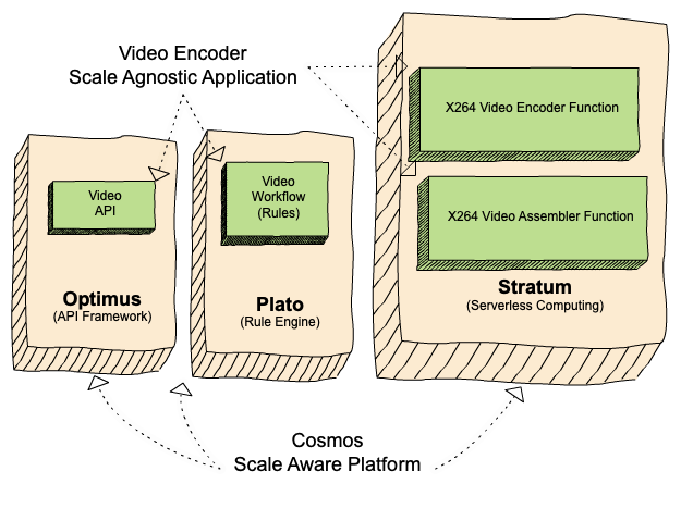
Cosmos is the next generation media computing platform at Netflix. Combining microservice architecture with asynchronous workflows and serverless functions, Cosmos aims to modernize Netflix’s media processing pipelines with improved flexibility, efficiency, and developer productivity. In the past few years, the video team within Encoding Technologies (ET) has been working on rebuilding the entire video pipeline on Cosmos.

This new pipeline is composed of a number of microservices, each dedicated to a single functionality. One such microservice is Video Encoding Service (VES). Encoding is an essential component of the video pipeline. At a high level, it takes an ingested mezzanine and encodes it into a video stream that is suitable for Netflix streaming or serves some studio/production use case. In the case of Netflix, there are a number of requirements for this service:

  • Given the wide range of devices from mobile phones to browsers to Smart TVs, multiple codec formats, resolutions, and quality levels need to be supported.
  • Chunked encoding is a must to meet the latency requirements of our business needs, and use cases with different levels of latency sensitivity need to be accommodated.
  • The capability of continuous release is crucial for enabling fast product innovation in both streaming and studio spaces.
  • There is a huge volume of encoding jobs every day. The service needs to be cost-efficient and make the most use of available resources.

In this tech blog, we will walk through how we built VES to achieve the above goals and will share a number of lessons we learned from building microservices. Please note that for simplicity, we have chosen to omit certain Netflix-specific details that are not integral to the primary message of this blog post.

Building Video Encoding Service on Cosmos

A Cosmos microservice consists of three layers: an API layer (Optimus) that takes in requests, a workflow layer (Plato) that orchestrates the media processing flows, and a serverless computing layer (Stratum) that processes the media. These three layers communicate asynchronously through a home-grown, priority-based messaging system called Timestone. We chose Protobuf as the payload format for its high efficiency and mature cross-platform support.

To help service developers get a head start, the Cosmos platform provides a powerful service generator. This generator features an intuitive UI. With a few clicks, it creates a basic yet complete Cosmos service: code repositories for all 3 layers are created; all platform capabilities, including discovery, logging, tracing, etc., are enabled; release pipelines are set up and dashboards are readily accessible. We can immediately start adding video encoding logic and deploy the service to the cloud for experimentation.

Optimus

As the API layer, Optimus serves as the gateway into VES, meaning service users can only interact with VES through Optimus. The defined API interface is a strong contract between VES and the external world. As long as the API is stable, users are shielded from internal changes in VES. This decoupling is instrumental in enabling faster iterations of VES internals.

As a single-purpose service, the API of VES is quite clean. We defined an endpoint encodeVideo that takes an EncodeRequest and returns an EncodeResponse (in an async way through Timestone messages). The EncodeRequest object contains information about the source video as well as the encoding recipe. All the requirements of the encoded video (codec, resolution, etc.) as well as the controls for latency (chunking directives) are exposed through the data model of the encoding recipe.

//protobuf definition 

message EncodeRequest {
VideoSource video_source = 1;//source to be encoded
Recipe recipe = 2; //including encoding format, resolution, etc.
}

message EncodeResponse {
OutputVideo output_video = 1; //encoded video
Error error = 2; //error message (optional)
}

message Recipe {
Codec codec = 1; //including codec format, profile, level, etc.
Resolution resolution = 2;
ChunkingDirectives chunking_directives = 3;
...
}

Like any other Cosmos service, the platform automatically generates an RPC client based on the VES API data model, which users can use to build the request and invoke VES. Once an incoming request is received, Optimus performs validations, and (when applicable) converts the incoming data into an internal data model before passing it to the next layer, Plato.

Like any other Cosmos service, the platform automatically generates an RPC client based on the VES API data model, which users can use to build the request and invoke VES. Once an incoming request is received, Optimus performs validations, and (when applicable) converts the incoming data into an internal data model before passing it to the next layer, Plato.

Plato

The workflow layer, Plato, governs the media processing steps. The Cosmos platform supports two programming paradigms for Plato: forward chaining rule engine and Directed Acyclic Graph (DAG). VES has a linear workflow, so we chose DAG for its simplicity.

In a DAG, the workflow is represented by nodes and edges. Nodes represent stages in the workflow, while edges signify dependencies — a stage is only ready to execute when all its dependencies have been completed. VES requires parallel encoding of video chunks to meet its latency and resilience goals. This workflow-level parallelism is facilitated by the DAG through a MapReduce mode. Nodes can be annotated to indicate this relationship, and a Reduce node will only be triggered when all its associated Map nodes are ready.

For the VES workflow, we defined five Nodes and their associated edges, which are visualized in the following graph:

  • Splitter Node: This node divides the video into chunks based on the chunking directives in the recipe.
  • Encoder Node: This node encodes a video chunk. It is a Map node.
  • Assembler Node: This node stitches the encoded chunks together. It is a Reduce node.
  • Validator Node: This node performs the validation of the encoded video.
  • Notifier Node: This node notifies the API layer once the entire workflow is completed.
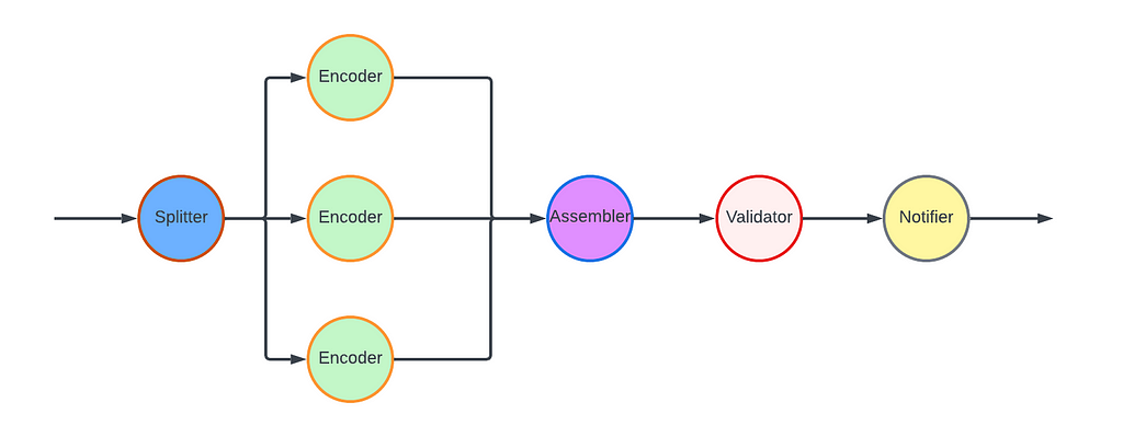
In this workflow, nodes such as the Notifier perform very lightweight operations and can be directly executed in the Plato runtime. However, resource-intensive operations need to be delegated to the computing layer (Stratum), or another service. Plato invokes Stratum functions for tasks such as encoding and assembling, where the nodes (Encoder and Assembler) post messages to the corresponding message queues. The Validator node calls another Cosmos service, the Video Validation Service, to validate the assembled encoded video.

Stratum

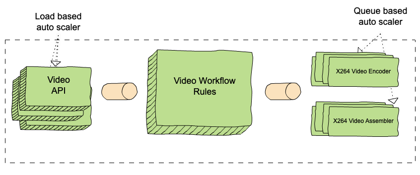
The computing layer, Stratum, is where media samples can be accessed. Developers of Cosmos services create Stratum Functions to process the media. They can bring their own media processing tools, which are packaged into Docker images of the Functions. These Docker images are then published to our internal Docker registry, part of Titus. In production, Titus automatically scales instances based on the depths of job queues.

VES needs to support encoding source videos into a variety of codec formats, including AVC, AV1, and VP9, to name a few. We use different encoder binaries (referred to simply as “encoders”) for different codec formats. For AVC, a format that is now 20 years old, the encoder is quite stable. On the other hand, the newest addition to Netflix streaming, AV1, is continuously going through active improvements and experimentations, necessitating more frequent encoder upgrades. ​​To effectively manage this variability, we decided to create multiple Stratum Functions, each dedicated to a specific codec format and can be released independently. This approach ensures that upgrading one encoder will not impact the VES service for other codec formats, maintaining stability and performance across the board.

Within the Stratum Function, the Cosmos platform provides abstractions for common media access patterns. Regardless of file formats, sources are uniformly presented as locally mounted frames. Similarly, for output that needs to be persisted in the cloud, the platform presents the process as writing to a local file. All details, such as streaming of bytes and retrying on errors, are abstracted away. With the platform taking care of the complexity of the infrastructure, the essential code for video encoding in the Stratum Function could be as simple as follows.

ffmpeg -i input/source%08d.j2k -vf ... -c:v libx264 ... output/encoding.264

Encoding is a resource-intensive process, and the resources required are closely related to the codec format and the encoding recipe. We conducted benchmarking to understand the resource usage pattern, particularly CPU and RAM, for different encoding recipes. Based on the results, we leveraged the “container shaping” feature from the Cosmos platform.

We defined a number of different “container shapes”, specifying the allocations of resources like CPU and RAM.

# an example definition of container shape
group: containerShapeExample1
resources:
numCpus: 2
memoryInMB: 4000
networkInMbp: 750
diskSizeInMB: 12000

Routing rules are created to assign encoding jobs to different shapes based on the combination of codec format and encoding resolution. This helps the platform perform “bin packing”, thereby maximizing resource utilization.
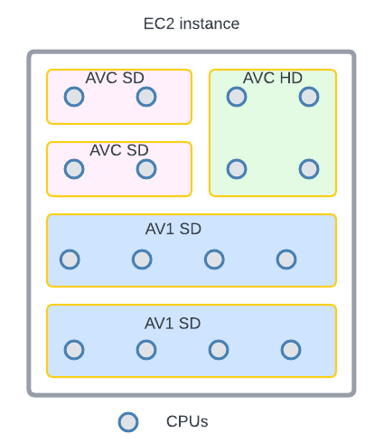
An example of “bin-packing”. The circles represent CPU cores and the area represents the RAM. This 16-core EC2 instance is packed with 5 encoding containers (rectangles) of 3 different shapes (indicated by different colors).

Continuous Release

After we completed the development and testing of all three layers, VES was launched in production. However, this did not mark the end of our work. Quite the contrary, we believed and still do that a significant part of a service’s value is realized through iterations: supporting new business needs, enhancing performance, and improving resilience. An important piece of our vision was for Cosmos services to have the ability to continuously release code changes to production in a safe manner.

Focusing on a single functionality, code changes pertaining to a single feature addition in VES are generally small and cohesive, making them easy to review. Since callers can only interact with VES through its API, internal code is truly “implementation details” that are safe to change. The explicit API contract limits the test surface of VES. Additionally, the Cosmos platform provides a pyramid-based testing framework to guide developers in creating tests at different levels.

After testing and code review, changes are merged and are ready for release. The release pipeline is fully automated: after the merge, the pipeline checks out code, compiles, builds, runs unit/integration/end-to-end tests as prescribed, and proceeds to full deployment if no issues are encountered. Typically, it takes around 30 minutes from code merge to feature landing (a process that took 2–4 weeks in our previous generation platform!). The short release cycle provides faster feedback to developers and helps them make necessary updates while the context is still fresh.

Screenshot of a release pipeline run in our production environment

When running in production, the service constantly emits metrics and logs. They are collected by the platform to visualize dashboards and to drive monitoring/alerting systems. Metrics deviating too much from the baseline will trigger alerts and can lead to automatic service rollback (when the “canary” feature is enabled).

The Learnings:

VES was the very first microservice that our team built. We started with basic knowledge of microservices and learned a multitude of lessons along the way. These learnings deepened our understanding of microservices and have helped us improve our design choices and decisions.

Define a Proper Service Scope

A principle of microservice architecture is that a service should be built for a single functionality. This sounds straightforward, but what exactly qualifies a “single functionality”? “Encoding video” sounds good but wouldn’t “encode video into the AVC format” be an even more specific single-functionality?

When we started building the VES, we took the approach of creating a separate encoding service for each codec format. While this has advantages such as decoupled workflows, quickly we were overwhelmed by the development overhead. Imagine that a user requested us to add the watermarking capability to the encoding. We needed to make changes to multiple microservices. What is worse, changes in all these services are very similar and essentially we are adding the same code (and tests) again and again. Such kind of repetitive work can easily wear out developers.

The service presented in this blog is our second iteration of VES (yes, we already went through one iteration). In this version, we consolidated encodings for different codec formats into a single service. They share the same API and workflow, while each codec format has its own Stratum Functions. So far this seems to strike a good balance: the common API and workflow reduces code repetition, while separate Stratum Functions guarantee independent evolution of each codec format.

The changes we made are not irreversible. If someday in the future, the encoding of one particular codec format evolves into a totally different workflow, we have the option to spin it off into its own microservice.

Be Pragmatic about Data Modeling

In the beginning, we were very strict about data model separation — we had a strong belief that sharing equates to coupling, and coupling could lead to potential disasters in the future. To avoid this, for each service as well as the three layers within a service, we defined its own data model and built converters to translate between different data models.

We ended up creating multiple data models for aspects such as bit-depth and resolution across our system. To be fair, this does have some merits. For example, our encoding pipeline supports different bit-depths for AVC encoding (8-bit) and AV1 encoding (10-bit). By defining both AVC.BitDepth and AV1.BitDepth, constraints on the bit-depth can be built into the data models. However, it is debatable whether the benefits of this differentiation power outweigh the downsides, namely multiple data model translations.

Eventually, we created a library to host data models for common concepts in the video domain. Examples of such concepts include frame rate, scan type, color space, etc. As you can see, they are extremely common and stable. This “common” data model library is shared across all services owned by the video team, avoiding unnecessary duplications and data conversions. Within each service, additional data models are defined for service-specific objects.

Embrace Service API Changes

This may sound contradictory. We have been saying that an API is a strong contract between the service and its users, and keeping an API stable shields users from internal changes. This is absolutely true. However, none of us had a crystal ball when we were designing the very first version of the service API. It is inevitable that at a certain point, this API becomes inadequate. If we hold the belief that “the API cannot change” too dearly, developers would be forced to find workarounds, which are almost certainly sub-optimal.

There are many great tech articles about gracefully evolving API. We believe we also have a unique advantage: VES is a service internal to Netflix Encoding Technologies (ET). Our two users, the Streaming Workflow Orchestrator and the Studio Workflow Orchestrator, are owned by the workflow team within ET. Our teams share the same contexts and work towards common goals. If we believe updating API is in the best interest of Netflix, we meet with them to seek alignment. Once a consensus to update the API is reached, teams collaborate to ensure a smooth transition.

Stay Tuned…

This is the second part of our tech blog series Rebuilding Netflix Video Pipeline with Microservices. In this post, we described the building process of the Video Encoding Service (VES) in detail as well as our learnings. Our pipeline includes a few other services that we plan to share about as well. Stay tuned for our future blogs on this topic of microservices!


The Making of VES: the Cosmos Microservice for Netflix Video Encoding was originally published in Netflix TechBlog on Medium, where people are continuing the conversation by highlighting and responding to this story.

Top Architecture Blog Posts of 2023

Post Syndicated from Andrea Courtright original https://aws.amazon.com/blogs/architecture/top-architecture-blog-posts-of-2023/

2023 was a rollercoaster year in tech, and we at the AWS Architecture Blog feel so fortunate to have shared in the excitement. As we move into 2024 and all of the new technologies we could see, we want to take a moment to highlight the brightest stars from 2023.

As always, thanks to our readers and to the many talented and hardworking Solutions Architects and other contributors to our blog.

I give you our 2023 cream of the crop!

#10: Build a serverless retail solution for endless aisle on AWS

In this post, Sandeep and Shashank help retailers and their customers alike in this guided approach to finding inventory that doesn’t live on shelves.

Building endless aisle architecture for order processing

Figure 1. Building endless aisle architecture for order processing

Check it out!

#9: Optimizing data with automated intelligent document processing solutions

Who else dreads wading through large amounts of data in multiple formats? Just me? I didn’t think so. Using Amazon AI/ML and content-reading services, Deependra, Anirudha, Bhajandeep, and Senaka have created a solution that is scalable and cost-effective to help you extract the data you need and store it in a format that works for you.

AI-based intelligent document processing engine

Figure 2: AI-based intelligent document processing engine

Check it out!

#8: Disaster Recovery Solutions with AWS managed services, Part 3: Multi-Site Active/Passive

Disaster recovery posts are always popular, and this post by Brent and Dhruv is no exception. Their creative approach in part 3 of this series is most helpful for customers who have business-critical workloads with higher availability requirements.

Warm standby with managed services

Figure 3. Warm standby with managed services

Check it out!

#7: Simulating Kubernetes-workload AZ failures with AWS Fault Injection Simulator

Continuing with the theme of “when bad things happen,” we have Siva, Elamaran, and Re’s post about preparing for workload failures. If resiliency is a concern (and it really should be), the secret is test, test, TEST.

Architecture flow for Microservices to simulate a realistic failure scenario

Figure 4. Architecture flow for Microservices to simulate a realistic failure scenario

Check it out!

#6: Let’s Architect! Designing event-driven architectures

Luca, Laura, Vittorio, and Zamira weren’t content with their four top-10 spots last year – they’re back with some things you definitely need to know about event-driven architectures.

Let's Architect

Figure 5. Let’s Architect artwork

Check it out!

#5: Use a reusable ETL framework in your AWS lake house architecture

As your lake house increases in size and complexity, you could find yourself facing maintenance challenges, and Ashutosh and Prantik have a solution: frameworks! The reusable ETL template with AWS Glue templates might just save you a headache or three.

Reusable ETL framework architecture

Figure 6. Reusable ETL framework architecture

Check it out!

#4: Invoking asynchronous external APIs with AWS Step Functions

It’s possible that AWS’ menagerie of services doesn’t have everything you need to run your organization. (Possible, but not likely; we have a lot of amazing services.) If you are using third-party APIs, then Jorge, Hossam, and Shirisha’s architecture can help you maintain a secure, reliable, and cost-effective relationship among all involved.

Invoking Asynchronous External APIs architecture

Figure 7. Invoking Asynchronous External APIs architecture

Check it out!

#3: Announcing updates to the AWS Well-Architected Framework

The Well-Architected Framework continues to help AWS customers evaluate their architectures against its six pillars. They are constantly striving for improvement, and Haleh’s diligence in keeping us up to date has not gone unnoticed. Thank you, Haleh!

Well-Architected logo

Figure 8. Well-Architected logo

Check it out!

#2: Let’s Architect! Designing architectures for multi-tenancy

The practically award-winning Let’s Architect! series strikes again! This time, Luca, Laura, Vittorio, and Zamira were joined by Federica to discuss multi-tenancy and why that concept is so crucial for SaaS providers.

Let's Architect

Figure 9. Let’s Architect

Check it out!

And finally…

#1: Understand resiliency patterns and trade-offs to architect efficiently in the cloud

Haresh, Lewis, and Bonnie revamped this 2022 post into a masterpiece that completely stole our readers’ hearts and is among the top posts we’ve ever made!

Resilience patterns and trade-offs

Figure 10. Resilience patterns and trade-offs

Check it out!

Bonus! Three older special mentions

These three posts were published before 2023, but we think they deserve another round of applause because you, our readers, keep coming back to them.

Thanks again to everyone for their contributions during a wild year. We hope you’re looking forward to the rest of 2024 as much as we are!

Rebuilding Netflix Video Processing Pipeline with Microservices

Post Syndicated from Netflix Technology Blog original https://netflixtechblog.com/rebuilding-netflix-video-processing-pipeline-with-microservices-4e5e6310e359

Liwei Guo, Anush Moorthy, Li-Heng Chen, Vinicius Carvalho, Aditya Mavlankar, Agata Opalach, Adithya Prakash, Kyle Swanson, Jessica Tweneboah, Subbu Venkatrav, Lishan Zhu

This is the first blog in a multi-part series on how Netflix rebuilt its video processing pipeline with microservices, so we can maintain our rapid pace of innovation and continuously improve the system for member streaming and studio operations. This introductory blog focuses on an overview of our journey. Future blogs will provide deeper dives into each service, sharing insights and lessons learned from this process.

The Netflix video processing pipeline went live with the launch of our streaming service in 2007. Since then, the video pipeline has undergone substantial improvements and broad expansions:

  • Starting with Standard Dynamic Range (SDR) at Standard-Definitions, we expanded the encoding pipeline to 4K and High Dynamic Range (HDR) which enabled support for our premium offering.
  • We moved from centralized linear encoding to distributed chunk-based encoding. This architecture shift greatly reduced the processing latency and increased system resiliency.
  • Moving away from the use of dedicated instances that were constrained in quantity, we tapped into Netflix’s internal trough created due to autoscaling microservices, leading to significant improvements in computation elasticity as well as resource utilization efficiency.
  • We rolled out encoding innovations such as per-title and per-shot optimizations, which provided significant quality-of-experience (QoE) improvement to Netflix members.
  • By integrating with studio content systems, we enabled the pipeline to leverage rich metadata from the creative side and create more engaging member experiences like interactive storytelling.
  • We expanded pipeline support to serve our studio/content-development use cases, which had different latency and resiliency requirements as compared to the traditional streaming use case.

Our experience of the last decade-and-a-half has reinforced our conviction that an efficient, flexible video processing pipeline that allows us to innovate and support our streaming service, as well as our studio partners, is critical to the continued success of Netflix. To that end, the Video and Image Encoding team in Encoding Technologies (ET) has spent the last few years rebuilding the video processing pipeline on our next-generation microservice-based computing platform Cosmos.

From Reloaded to Cosmos

Reloaded

Starting in 2014, we developed and operated the video processing pipeline on our third-generation platform Reloaded. Reloaded was well-architected, providing good stability, scalability, and a reasonable level of flexibility. It served as the foundation for numerous encoding innovations developed by our team.

When Reloaded was designed, we focused on a single use case: converting high-quality media files (also known as mezzanines) received from studios into compressed assets for Netflix streaming. Reloaded was created as a single monolithic system, where developers from various media teams in ET and our platform partner team Content Infrastructure and Solutions (CIS)¹ worked on the same codebase, building a single system that handled all media assets. Over the years, the system expanded to support various new use cases. This led to a significant increase in system complexity, and the limitations of Reloaded began to show:

  • Coupled functionality: Reloaded was composed of a number of worker modules and an orchestration module. The setup of a new Reloaded module and its integration with the orchestration required a non-trivial amount of effort, which led to a bias towards augmentation rather than creation when developing new functionalities. For example, in Reloaded the video quality calculation was implemented inside the video encoder module. With this implementation, it was extremely difficult to recalculate video quality without re-encoding.
  • Monolithic structure: Since Reloaded modules were often co-located in the same repository, it was easy to overlook code-isolation rules and there was quite a bit of unintended reuse of code across what should have been strong boundaries. Such reuse created tight coupling and reduced development velocity. The tight coupling among modules further forced us to deploy all modules together.
  • Long release cycles: The joint deployment meant that there was increased fear of unintended production outages as debugging and rollback can be difficult for a deployment of this size. This drove the approach of the “release train”. Every two weeks, a “snapshot” of all modules was taken, and promoted to be a “release candidate”. This release candidate then went through exhaustive testing which attempted to cover as large a surface area as possible. This testing stage took about two weeks. Thus, depending on when the code change was merged, it could take anywhere between two and four weeks to reach production.

As time progressed and functionalities grew, the rate of new feature contributions in Reloaded dropped. Several promising ideas were abandoned owing to the outsized work needed to overcome architectural limitations. The platform that had once served us well was now becoming a drag on development.

Cosmos

As a response, in 2018 the CIS and ET teams started developing the next-generation platform, Cosmos. In addition to the scalability and the stability that the developers already enjoyed in Reloaded, Cosmos aimed to significantly increase system flexibility and feature development velocity. To achieve this, Cosmos was developed as a computing platform for workflow-driven, media-centric microservices.

The microservice architecture provides strong decoupling between services. Per-microservice workflow support eases the burden of implementing complex media workflow logic. Finally, relevant abstractions allow media algorithm developers to focus on the manipulation of video and audio signals rather than on infrastructural concerns. A comprehensive list of benefits offered by Cosmos can be found in the linked blog.

Building the Video Processing Pipeline in Cosmos

Service Boundaries

In the microservice architecture, a system is composed of a number of fine-grained services, with each service focusing on a single functionality. So the first (and arguably the most important) thing is to identify boundaries and define services.

In our pipeline, as media assets travel through creation to ingest to delivery, they go through a number of processing steps such as analyses and transformations. We analyzed these processing steps to identify “boundaries” and grouped them into different domains, which in turn became the building blocks of the microservices we engineered.

As an example, in Reloaded, the video encoding module bundles 5 steps:

1. divide the input video into small chunks

2. encode each chunk independently

3. calculate the quality score (VMAF) of each chunk

4. assemble all the encoded chunks into a single encoded video

5. aggregate quality scores from all chunks

From a system perspective, the assembled encoded video is of primary concern while the internal chunking and separate chunk encodings exist in order to fulfill certain latency and resiliency requirements. Further, as alluded to above, the video quality calculation provides a totally separate functionality as compared to the encoding service.

Thus, in Cosmos, we created two independent microservices: Video Encoding Service (VES) and Video Quality Service (VQS), each of which serves a clear, decoupled function. As implementation details, the chunked encoding and the assembling were abstracted away into the VES.

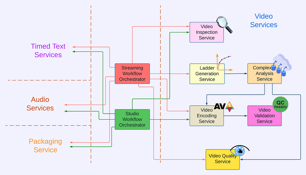
Video Services

The approach outlined above was applied to the rest of the video processing pipeline to identify functionalities and hence service boundaries, leading to the creation of the following video services².

  1. Video Inspection Service (VIS): This service takes a mezzanine as the input and performs various inspections. It extracts metadata from different layers of the mezzanine for downstream services. In addition, the inspection service flags issues if invalid or unexpected metadata is observed and provides actionable feedback to the upstream team.
  2. Complexity Analysis Service (CAS): The optimal encoding recipe is highly content-dependent. This service takes a mezzanine as the input and performs analysis to understand the content complexity. It calls Video Encoding Service for pre-encoding and Video Quality Service for quality evaluation. The results are saved to a database so they can be reused.
  3. Ladder Generation Service (LGS): This service creates an entire bitrate ladder for a given encoding family (H.264, AV1, etc.). It fetches the complexity data from CAS and runs the optimization algorithm to create encoding recipes. The CAS and LGS cover much of the innovations that we have previously presented in our tech blogs (per-title, mobile encodes, per-shot, optimized 4K encoding, etc.). By wrapping ladder generation into a separate microservice (LGS), we decouple the ladder optimization algorithms from the creation and management of complexity analysis data (which resides in CAS). We expect this to give us greater freedom for experimentation and a faster rate of innovation.
  4. Video Encoding Service (VES): This service takes a mezzanine and an encoding recipe and creates an encoded video. The recipe includes the desired encoding format and properties of the output, such as resolution, bitrate, etc. The service also provides options that allow fine-tuning latency, throughput, etc., depending on the use case.
  5. Video Validation Service (VVS): This service takes an encoded video and a list of expectations about the encode. These expectations include attributes specified in the encoding recipe as well as conformance requirements from the codec specification. VVS analyzes the encoded video and compares the results against the indicated expectations. Any discrepancy is flagged in the response to alert the caller.
  6. Video Quality Service (VQS): This service takes the mezzanine and the encoded video as input, and calculates the quality score (VMAF) of the encoded video.

Service Orchestration

Each video service provides a dedicated functionality and they work together to generate the needed video assets. Currently, the two main use cases of the Netflix video pipeline are producing assets for member streaming and for studio operations. For each use case, we created a dedicated workflow orchestrator so the service orchestration can be customized to best meet the corresponding business needs.

For the streaming use case, the generated videos are deployed to our content delivery network (CDN) for Netflix members to consume. These videos can easily be watched millions of times. The Streaming Workflow Orchestrator utilizes almost all video services to create streams for an impeccable member experience. It leverages VIS to detect and reject non-conformant or low-quality mezzanines, invokes LGS for encoding recipe optimization, encodes video using VES, and calls VQS for quality measurement where the quality data is further fed to Netflix’s data pipeline for analytics and monitoring purposes. In addition to video services, the Streaming Workflow Orchestrator uses audio and timed text services to generate audio and text assets, and packaging services to “containerize” assets for streaming.

For the studio use case, some example video assets are marketing clips and daily production editorial proxies. The requests from the studio side are generally latency-sensitive. For example, someone from the production team may be waiting for the video to review so they can decide the shooting plan for the next day. Because of this, the Studio Workflow Orchestrator optimizes for fast turnaround and focuses on core media processing services. At this time, the Studio Workflow Orchestrator calls VIS to extract metadata of the ingested assets and calls VES with predefined recipes. Compared to member streaming, studio operations have different and unique requirements for video processing. Therefore, the Studio Workflow Orchestrator is the exclusive user of some encoding features like forensic watermarking and timecode/text burn-in.

Where we are now

We have had the new video pipeline running alongside Reloaded in production for a few years now. During this time, we completed the migration of all necessary functionalities from Reloaded, began gradually shifting over traffic one use case at a time, and completed the switchover in September of 2023.

While it is still early days, we have already seen the benefits of the new platform, specifically the ease of feature delivery. Notably, Netflix launched the Advertising-supported plan in November 2022. Processing Ad creatives posed some new challenges: media formats of Ads are quite different from movie and TV mezzanines that the team was familiar with, and there was a new set of media processing requirements related to the business needs of Ads. With the modularity and developer productivity benefits of Cosmos, we were able to quickly iterate the pipeline to keep up with the changing requirements and support a successful product launch.

Summary

Rebuilding the video pipeline was a huge undertaking for the team. We are very proud of what we have achieved, and also eager to share our journey with the technical community. This blog has focused on providing an overview: a brief history of our pipeline and the platforms, why the rebuilding was necessary, what these new services look like, and how they are being used for Netflix businesses. In the next blog, we are going to delve into the details of the Video Encoding Service (VES), explaining step-by-step the service creation, and sharing lessons learned (we have A LOT!). We also plan to cover other video services in future tech blogs. Follow the Netflix Tech Blog to stay up to date.

Acknowledgments

A big shout out to the CIS team for their outstanding work in building the Cosmos platform and their receptiveness to feedback from service developers.

We want to express our appreciation to our users, the Streaming Encoding Pipeline team, and the Video Engineering team. Just like our feedback helps iron out the platform, the feedback from our users has been instrumental in building high-quality services.

We also want to thank Christos Bampis and Zhi Li for their significant contributions to video services, and our two former team members, Chao Chen and Megha Manohara for contributing to the early development of this project.

Footnotes

  1. Formerly known as Media Cloud Engineering/MCE team.
  2. The actual number of video services is more than listed here. Some of them are Netflix-specific and thus omitted from this blog.


Rebuilding Netflix Video Processing Pipeline with Microservices was originally published in Netflix TechBlog on Medium, where people are continuing the conversation by highlighting and responding to this story.

Zero Configuration Service Mesh with On-Demand Cluster Discovery

Post Syndicated from Netflix Technology Blog original https://netflixtechblog.com/zero-configuration-service-mesh-with-on-demand-cluster-discovery-ac6483b52a51

by David Vroom, James Mulcahy, Ling Yuan, Rob Gulewich

In this post we discuss Netflix’s adoption of service mesh: some history, motivations, and how we worked with Kinvolk and the Envoy community on a feature that streamlines service mesh adoption in complex microservice environments: on-demand cluster discovery.

A brief history of IPC at Netflix

Netflix was early to the cloud, particularly for large-scale companies: we began the migration in 2008, and by 2010, Netflix streaming was fully run on AWS. Today we have a wealth of tools, both OSS and commercial, all designed for cloud-native environments. In 2010, however, nearly none of it existed: the CNCF wasn’t formed until 2015! Since there were no existing solutions available, we needed to build them ourselves.

For Inter-Process Communication (IPC) between services, we needed the rich feature set that a mid-tier load balancer typically provides. We also needed a solution that addressed the reality of working in the cloud: a highly dynamic environment where nodes are coming up and down, and services need to quickly react to changes and route around failures. To improve availability, we designed systems where components could fail separately and avoid single points of failure. These design principles led us to client-side load-balancing, and the 2012 Christmas Eve outage solidified this decision even further. During these early years in the cloud, we built Eureka for Service Discovery and Ribbon (internally known as NIWS) for IPC. Eureka solved the problem of how services discover what instances to talk to, and Ribbon provided the client-side logic for load-balancing, as well as many other resiliency features. These two technologies, alongside a host of other resiliency and chaos tools, made a massive difference: our reliability improved measurably as a result.

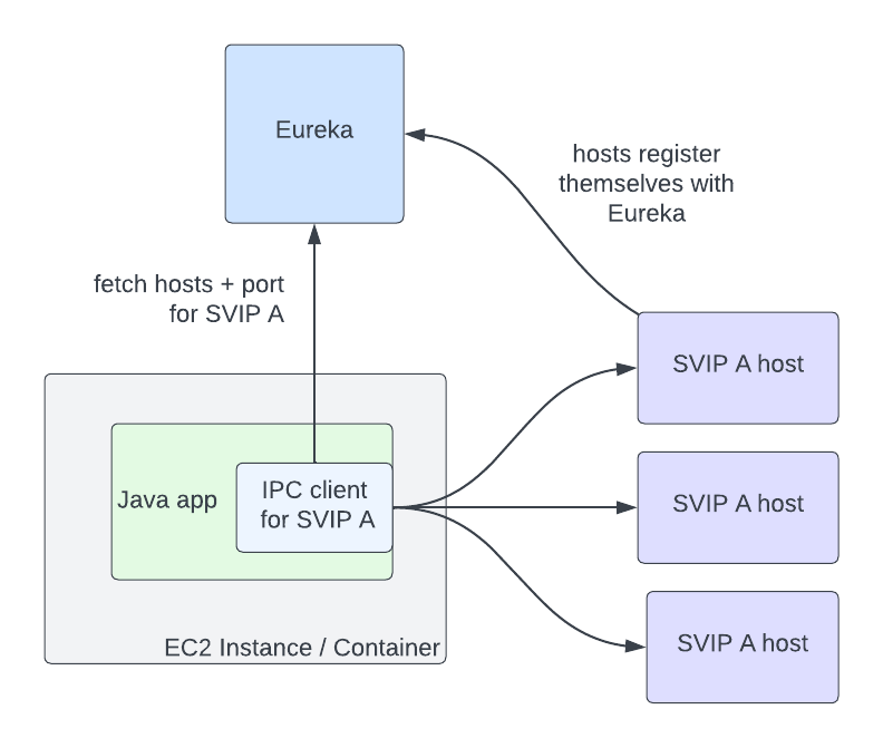
Eureka and Ribbon presented a simple but powerful interface, which made adopting them easy. In order for a service to talk to another, it needs to know two things: the name of the destination service, and whether or not the traffic should be secure. The abstractions that Eureka provides for this are Virtual IPs (VIPs) for insecure communication, and Secure VIPs (SVIPs) for secure. A service advertises a VIP name and port to Eureka (eg: myservice, port 8080), or an SVIP name and port (eg: myservice-secure, port 8443), or both. IPC clients are instantiated targeting that VIP or SVIP, and the Eureka client code handles the translation of that VIP to a set of IP and port pairs by fetching them from the Eureka server. The client can also optionally enable IPC features like retries or circuit breaking, or stick with a set of reasonable defaults.

A diagram showing an IPC client in a Java app directly communicating to hosts registered as SVIP A. Host and port information for SVIP A is fetched from Eureka by the IPC client.

In this architecture, service to service communication no longer goes through the single point of failure of a load balancer. The downside is that Eureka is a new single point of failure as the source of truth for what hosts are registered for VIPs. However, if Eureka goes down, services can continue to communicate with each other, though their host information will become stale over time as instances for a VIP come up and down. The ability to run in a degraded but available state during an outage is still a marked improvement over completely stopping traffic flow.

Why mesh?

The above architecture has served us well over the last decade, though changing business needs and evolving industry standards have added more complexity to our IPC ecosystem in a number of ways. First, we’ve grown the number of different IPC clients. Our internal IPC traffic is now a mix of plain REST, GraphQL, and gRPC. Second, we’ve moved from a Java-only environment to a Polyglot one: we now also support node.js, Python, and a variety of OSS and off the shelf software. Third, we’ve continued to add more functionality to our IPC clients: features such as adaptive concurrency limiting, circuit breaking, hedging, and fault injection have become standard tools that our engineers reach for to make our system more reliable. Compared to a decade ago, we now support more features, in more languages, in more clients. Keeping feature parity between all of these implementations and ensuring that they all behave the same way is challenging: what we want is a single, well-tested implementation of all of this functionality, so we can make changes and fix bugs in one place.

This is where service mesh comes in: we can centralize IPC features in a single implementation, and keep per-language clients as simple as possible: they only need to know how to talk to the local proxy. Envoy is a great fit for us as the proxy: it’s a battle-tested OSS product at use in high scale in the industry, with many critical resiliency features, and good extension points for when we need to extend its functionality. The ability to configure proxies via a central control plane is a killer feature: this allows us to dynamically configure client-side load balancing as if it was a central load balancer, but still avoids a load balancer as a single point of failure in the service to service request path.

Moving to mesh

Once we decided that moving to service mesh was the right bet to make, the next question became: how should we go about moving? We decided on a number of constraints for the migration. First: we wanted to keep the existing interface. The abstraction of specifying a VIP name plus secure serves us well, and we didn’t want to break backwards compatibility. Second: we wanted to automate the migration and to make it as seamless as possible. These two constraints meant that we needed to support the Discovery abstractions in Envoy, so that IPC clients could continue to use it under the hood. Fortunately, Envoy had ready to use abstractions for this. VIPs could be represented as Envoy Clusters, and proxies could fetch them from our control plane using the Cluster Discovery Service (CDS). The hosts in those clusters are represented as Envoy Endpoints, and could be fetched using the Endpoint Discovery Service (EDS).

We soon ran into a stumbling block to a seamless migration: Envoy requires that clusters be specified as part of the proxy’s config. If service A needs to talk to clusters B and C, then you need to define clusters B and C as part of A’s proxy config. This can be challenging at scale: any given service might communicate with dozens of clusters, and that set of clusters is different for every app. In addition, Netflix is always changing: we’re constantly adding new initiatives like live streaming, ads and games, and evolving our architecture. This means the clusters that a service communicates with will change over time. There are a number of different approaches to populating cluster config that we evaluated, given the Envoy primitives available to us:

  1. Get service owners to define the clusters their service needs to talk to. This option seems simple, but in practice, service owners don’t always know, or want to know, what services they talk to. Services often import libraries provided by other teams that talk to multiple other services under the hood, or communicate with other operational services like telemetry and logging. This means that service owners would need to know how these auxiliary services and libraries are implemented under the hood, and adjust config when they change.
  2. Auto-generate Envoy config based on a service’s call graph. This method is simple for pre-existing services, but is challenging when bringing up a new service or adding a new upstream cluster to communicate with.
  3. Push all clusters to every app: this option was appealing in its simplicity, but back of the napkin math quickly showed us that pushing millions of endpoints to each proxy wasn’t feasible.

Given our goal of a seamless adoption, each of these options had significant enough downsides that we explored another option: what if we could fetch cluster information on-demand at runtime, rather than predefining it? At the time, the service mesh effort was still being bootstrapped, with only a few engineers working on it. We approached Kinvolk to see if they could work with us and the Envoy community in implementing this feature. The result of this collaboration was On-Demand Cluster Discovery (ODCDS). With this feature, proxies could now look up cluster information the first time they attempt to connect to it, rather than predefining all of the clusters in config.

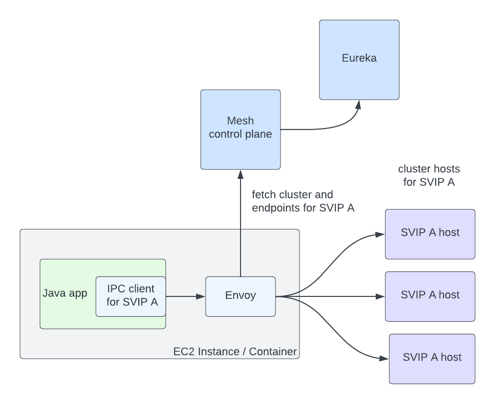
With this capability in place, we needed to give the proxies cluster information to look up. We had already developed a service mesh control plane that implements the Envoy XDS services. We then needed to fetch service information from Eureka in order to return to the proxies. We represent Eureka VIPs and SVIPs as separate Envoy Cluster Discovery Service (CDS) clusters (so service myservice may have clusters myservice.vip and myservice.svip). Individual hosts in a cluster are represented as separate Endpoint Discovery Service (EDS) endpoints. This allows us to reuse the same Eureka abstractions, and IPC clients like Ribbon can move to mesh with minimal changes. With both the control plane and data plane changes in place, the flow works as follows:

  1. Client request comes into Envoy
  2. Extract the target cluster based on the Host / :authority header (the header used here is configurable, but this is our approach). If that cluster is known already, jump to step 7
  3. The cluster doesn’t exist, so we pause the in flight request
  4. Make a request to the Cluster Discovery Service (CDS) endpoint on the control plane. The control plane generates a customized CDS response based on the service’s configuration and Eureka registration information
  5. Envoy gets back the cluster (CDS), which triggers a pull of the endpoints via Endpoint Discovery Service (EDS). Endpoints for the cluster are returned based on Eureka status information for that VIP or SVIP
  6. Client request unpauses
  7. Envoy handles the request as normal: it picks an endpoint using a load-balancing algorithm and issues the request

This flow is completed in a few milliseconds, but only on the first request to the cluster. Afterward, Envoy behaves as if the cluster was defined in the config. Critically, this system allows us to seamlessly migrate services to service mesh with no configuration required, satisfying one of our main adoption constraints. The abstraction we present continues to be VIP name plus secure, and we can migrate to mesh by configuring individual IPC clients to connect to the local proxy instead of the upstream app directly. We continue to use Eureka as the source of truth for VIPs and instance status, which allows us to support a heterogeneous environment of some apps on mesh and some not while we migrate. There’s an additional benefit: we can keep Envoy memory usage low by only fetching data for clusters that we’re actually communicating with.

A diagram showing an IPC client in a Java app communicating through Envoy to hosts registered as SVIP A. Cluster and endpoint information for SVIP A is fetched from the mesh control plane by Envoy. The mesh control plane fetches host information from Eureka.

There is a downside to fetching this data on-demand: this adds latency to the first request to a cluster. We have run into use-cases where services need very low-latency access on the first request, and adding a few extra milliseconds adds too much overhead. For these use-cases, the services need to either predefine the clusters they communicate with, or prime connections before their first request. We’ve also considered pre-pushing clusters from the control plane as proxies start up, based on historical request patterns. Overall, we feel the reduced complexity in the system justifies the downside for a small set of services.

We’re still early in our service mesh journey. Now that we’re using it in earnest, there are many more Envoy improvements that we’d love to work with the community on. The porting of our adaptive concurrency limiting implementation to Envoy was a great start — we’re looking forward to collaborating with the community on many more. We’re particularly interested in the community’s work on incremental EDS. EDS endpoints account for the largest volume of updates, and this puts undue pressure on both the control plane and Envoy.

We’d like to give a big thank-you to the folks at Kinvolk for their Envoy contributions: Alban Crequy, Andrew Randall, Danielle Tal, and in particular Krzesimir Nowak for his excellent work. We’d also like to thank the Envoy community for their support and razor-sharp reviews: Adi Peleg, Dmitri Dolguikh, Harvey Tuch, Matt Klein, and Mark Roth. It’s been a great experience working with you all on this.

This is the first in a series of posts on our journey to service mesh, so stay tuned. If this sounds like fun, and you want to work on service mesh at scale, come work with us — we’re hiring!


Zero Configuration Service Mesh with On-Demand Cluster Discovery was originally published in Netflix TechBlog on Medium, where people are continuing the conversation by highlighting and responding to this story.

Let’s Architect! DevOps Best Practices on AWS

Post Syndicated from Luca Mezzalira original https://aws.amazon.com/blogs/architecture/lets-architect-devops-best-practices-on-aws/

DevOps has revolutionized software development and operations by fostering collaboration, automation, and continuous improvement. By bringing together development and operations teams, organizations can accelerate software delivery, enhance reliability, and achieve faster time-to-market.

In this blog post, we will explore the best practices and architectural considerations for implementing DevOps with Amazon Web Services (AWS), enabling you to build efficient and scalable systems that align with DevOps principles. The Let’s Architect! team wants to share useful resources that help you to optimize your software development and operations.

DevOps revolution

Distributed systems are adopted from enterprises more frequently now. When an organization wants to leverage distributed systems’ characteristics, it requires a mindset and approach shift, akin to a new model for software development lifecycle.

In this re:Invent 2021 video, Emily Freeman, now Head of Community Engagement at AWS, shares with us the insights gained in the trenches when adapting a new software development lifecycle that will help your organization thrive using distributed systems.

Take me to this re:Invent 2021 video!

Operationalizing the DevOps revolution

Operationalizing the DevOps revolution

My CI/CD pipeline is my release captain

Designing effective DevOps workflows is necessary for achieving seamless collaboration between development and operations teams. The Amazon Builders’ Library offers a wealth of guidance on designing DevOps workflows that promote efficiency, scalability, and reliability. From continuous integration and deployment strategies to configuration management and observability, this resource covers various aspects of DevOps workflow design. By following the best practices outlined in the Builders’ Library, you can create robust and scalable DevOps workflows that facilitate rapid software delivery and smooth operations.

Take me to this resource!

A pipeline coordinates multiple inflight releases and promotes them through three stages

A pipeline coordinates multiple inflight releases and promotes them through three stages

Using Cloud Fitness Functions to Drive Evolutionary Architecture

Cloud fitness functions provide a powerful mechanism for driving evolutionary architecture within your DevOps practices. By defining and measuring architectural fitness goals, you can continuously improve and evolve your systems over time.

This AWS Architecture Blog post delves into how AWS services, like AWS Lambda, AWS Step Functions, and Amazon CloudWatch can be leveraged to implement cloud fitness functions effectively. By integrating these services into your DevOps workflows, you can establish an architecture that evolves in alignment with changing business needs: improving system resilience, scalability, and maintainability.

Take me to this AWS Architecture Blog post!

Fitness functions provide feedback to engineers via metrics

Fitness functions provide feedback to engineers via metrics

Multi-Region Terraform Deployments with AWS CodePipeline using Terraform Built CI/CD

Achieving consistent deployments across multiple regions is a common challenge. This AWS DevOps Blog post demonstrates how to use Terraform, AWS CodePipeline, and infrastructure-as-code principles to automate Multi-Region deployments effectively. By adopting this approach, you can demonstrate the consistent infrastructure and application deployments, improving the scalability, reliability, and availability of your DevOps practices.

The post also provides practical examples and step-by-step instructions for implementing Multi-Region deployments with Terraform and AWS services, enabling you to leverage the power of infrastructure-as-code to streamline DevOps workflows.

Take me to this AWS DevOps Blog post!

Multi-Region AWS deployment with IaC and CI/CD pipelines

Multi-Region AWS deployment with IaC and CI/CD pipelines

See you next time!

Thanks for joining our discussion on DevOps best practices! Next time we’ll talk about how to create resilient workloads on AWS.

To find all the blogs from this series, check out the Let’s Architect! list of content on the AWS Architecture Blog. See you soon!

Let’s Architect! Multi-tenant SaaS architectures

Post Syndicated from Luca Mezzalira original https://aws.amazon.com/blogs/architecture/lets-architect-multi-tenant-saas-architectures/

In a multi-tenant architecture multiple instances of an application run on a shared infrastructure. With this type of approach, each tenant is isolated from others, typically through logical separation, while utilizing a shared infrastructure. This allows multiple tenants to use the same application and maintain their data security, privacy, and customization requirements.

Understanding architectural patterns for multi-tenancy has become crucial for architects and developers aiming to deliver scalable, secure, and cost-effective solutions. Isolating tenant data is a fundamental responsibility for Software as a Service (SaaS) providers. In this edition of Let’s Architect!, we talk about comprehensive exploration of multi-tenant architectures, covering various aspects, such as SaaS microservices, SaaS serverless, SaaS EKS, and an insightful whitepaper.

SaaS microservices deep dive: Simplifying multi-tenant development

In this session, Michael Beardsley, Principal Solutions Architect at AWS, takes a deep dive into the realm of multi-tenant microservices, exploring various patterns and strategies that enable the seamless implementation of multi-tenant microservices, all while ensuring that additional complexity is not imposed upon the SaaS builders. He shares practical patterns to simplify the development process by addressing crucial aspect, such as authorization, data access, tenant isolation, metrics, billing, logging, and a plethora of other considerations; this is irrespective of the chosen compute platform (like Amazon Elastic Container Service, Amazon Elastic Kubernetes Service [Amazon EKS], or AWS Lambda) or database solution.

There is another session available that highlights specific techniques and architecture strategies that can directly impact the success of a SaaS business. If you’re interested in learning more about optimizing multi-tenant SaaS architecture, this session is a great opportunity.

Take me to this video!

SaaS multi-tenant microservices

SaaS multi-tenant microservices

Building a Multi-Tenant SaaS Solution Using AWS Serverless Services

In this AWS Partner Network (APN) Blog post, you will explore a reference solution that presents a comprehensive perspective on a functional multi-tenant serverless SaaS environment. This solution effectively showcases various essential components required to construct a multi-tenant SaaS solution using serverless services, including onboarding processes, tenant isolation mechanisms, data partitioning techniques, a tenant deployment pipeline, and robust observability measures.

By delving into these aspects, you can gain valuable insights into the architecture and design considerations involved in creating a successful multi-tenant SaaS solution.

Take me to this AWS APN blogpost!

Tenant registration flow

Tenant registration flow

Amazon EKS SaaS deep dive: A multi-tenant EKS SaaS solution

In this re:Invent 2021 presentation, Tod Golding, Principal Partner Solutions Architect, chats about a SaaS reference solution that addresses fundamental multi-tenant considerations, examining its approach to core SaaS topics, including tenant isolation, identity, onboarding, tenant administration, and data partitioning. The goal is to explore an Amazon EKS SaaS architecture through the lens of working code and highlight the key architectural strategies that were used in this reference environment.

There is also valuable information available on Github regarding EKS multi-tenancy. Exploring the Github repositories related to EKS multi-tenancy can provide further insights, resources, and practical examples for implementing multi-tenant architectures on EKS. This presentation is an engaging way to dive deeper into this topic and gain a more comprehensive understanding of best practices and real-world implementations.

Take me to this video!

Tenant deployment model

Tenant deployment model

Saas Storage Strategies

Storage represents a challenging aspect of building and delivering multi-tenant software solutions. There are different strategies that can be used to partition tenant data, each with a unique set of trade-offs for implementing separation between tenants. This whitepaper covers different storage models for multi-tenancy; in particular, you can learn about the:

  • Silo model (data from the tenant is fully isolated)
  • Pool model (all the tenants use the same database and table)
  • Bridge model (single database but a different table for each tenant)

For each of these models, the whitepaper describes in detail how they can be implemented, as well as the different trade-offs in terms of isolation and agility. You can also discover how these tenancy models can be implemented specifically on databases, such as Amazon DynamoDB and Amazon Relational Database Service, thus covering both NoSQL and SQL scenarios.

Take me to this whitepaper!

Partitioning model tradeoffs

Partitioning model tradeoffs

See you next time!

Thanks for joining our conversation on multi-tenant SaaS architectures! Next time, we’ll talk about open-source technologies.

To find all the blogs from this series, you can check out the Let’s Architect! list of content on the AWS Architecture Blog.

Let’s Architect! Designing microservices architectures

Post Syndicated from Luca Mezzalira original https://aws.amazon.com/blogs/architecture/lets-architect-designing-microservices-architectures/

In 2022, we published Let’s Architect! Architecting microservices with containers. We covered integrations patterns and some approaches for implementing microservices using containers. In this Let’s Architect! post, we want to drill down into microservices only, by focusing on the main challenges that software architects and engineers face while working on large distributed systems structured as a set of independent services.

There are many considerations to cover in detail within a broad topic like microservices. We should reflect on the organizational structure, automation pipelines, multi-account strategy, testing, communication, and many other areas. With this post we dive deep into the topic by analyzing the options for discoverability and connectivity available through Amazon VPC Lattice; then, we focus on architectural patterns for communication, mainly on asynchronous communication, as it fits very well into the paradigm. Finally, we explore how to work with serverless microservices and analyze a case study from Amazon, coming directly from the Amazon Builder’s Library.

AWS Container Day featuring Kubernetes

Modern applications are often built using a microservice distributed approach, which involves dividing the application into smaller, specialized services. Each of these services implement their own subset of functionalities or business logic. To facilitate communication between these services, it is essential to have a method to authorize, route, and monitor network traffic. It is also important, in case of issues, to have the ability of identifying the root cause of an issue, whether it originates at the application, service, or network level.

Amazon VPC Lattice can offer a consistent way to connect, secure, and monitor communication between instances, containers, and serverless functions. With Amazon VPC Lattice, you can define policies for traffic management, network access, advanced routing, implement discoverability, and, at the same time, monitor how the traffic is flowing inside complex applications in near real time.

Take me to this video!

Amazon VPC Lattice service gives you a consistent way to connect, secure, and monitor communication between your services

Amazon VPC Lattice service gives you a consistent way to connect, secure, and monitor communication between your services

Application integration patterns for microservices

Loosely coupled integration can help you design independent systems that can be developed and operated individually, plus increase the availability and reliability of the overall system landscape—particularly by using asynchronous communication. While there are many approaches for integration and conversation scenarios, it’s not always clear which approach is best for a given situation.

Join this re:Invent 2022 session to learn about foundational patterns for integration and conversation scenarios with an emphasis on loose coupling and asynchronous communication. Explore real-world use cases architected with cloud-native and serverless services, and receive guidance on choosing integration technology.

Take me to this re:Invent 2022 video!

Loosely coupled integration can help you design independent systems that can be developed and operated individually and can also increase the availability and reliability of the overall system

Loosely coupled integration can help you design independent systems that can be developed and operated individually and can also increase the availability and reliability of the overall system

Design patterns for success in serverless microservices

Software engineers love patterns—proven approaches to well-known problems that make software development easier and set our projects up for success. In complex, distributed systems, such as microservices, patterns like CQRS and Event Sourcing help decouple and scale systems.

The first part of the video is all about introducing architectural patterns and their applications, while the second part contains a set of demos and examples from the AWS console.
In this session, we examine at some typical patterns for building robust and performant serverless microservices, and how data access patterns can drive polyglot persistence.

Take me to this AWS Summit video!

With Event Sourcing data is stored as a series of events, instead of direct updates to data stores. Microservices replay events from an event store to compute the appropriate state of their own data stores

With event sourcing data is stored as a series of events, instead of direct updates to data stores; microservices replay events from an event store to compute the appropriate state of their own data stores

Avoiding overload in distributed systems by putting the smaller service in control

If we don’t pay attention to the relative scale of a service and its clients, distributed systems with microservices can be at risk of overload. A common architecture pattern adopted by many AWS services consists of splitting the system in a control plane and a data plane.

This article drills down into this scenario to understand what could happen if the data plane fleet exceeds the scale of the control plane fleet by a factor of 100 or more. This can happen in a microservices-based architecture when service X recovers from an outage and starts sending a large amount of request to service Y. Without careful fine-tuning, this shift in behavior can overwhelm the smaller callee. With this resource, we want to share some mental models and design strategies that are beneficial for distributed systems and teams working on microservices architectures.

Take me to the Amazon Builders’ Library!

To stay up to date on the data plane’s operational state, the control plane can poll an Amazon S3 bucket into which data plane servers periodically write that information

To stay updated on the data plane’s operational state, the control plane can poll an Amazon S3 bucket into which data plane servers periodically write that information

See you next time!

Thanks for stopping by! Join us in two weeks when we’ll discuss multi-tenancy and patterns for SaaS on AWS.

To find all the blogs from this series, you can check out the Let’s Architect! list of content on the AWS Architecture Blog.

Let’s Architect! Designing event-driven architectures

Post Syndicated from Luca Mezzalira original https://aws.amazon.com/blogs/architecture/lets-architect-designing-event-driven-architectures/

During the design of distributed systems, we have to identify a communication strategy to exchange information between different services while keeping the evolutionary nature of the architecture in mind. Event-driven architectures are based on events (facts that happened in a system), which are asynchronously exchanged to implement communication across different services while having a high degree of decoupling. This paradigm also allows us to run code in response to events, with benefits like cost optimization and sustainability for the entire infrastructure.

In this edition of Let’s Architect!, we share architectural resources to introduce event-driven architectures, how to build them on AWS, and how to approach the design phase.

AWS re:Invent 2022 – Keynote with Dr. Werner Vogels

re:Invent 2022 may be finished, but the keynote given by Amazon’s Chief Technology Officer, Dr. Werner Vogels, will not be forgotten. Vogels not only covered the announcements of new services but also event-driven architecture foundations in conjunction with customers’ stories on how this architecture helped to improve their systems.

Take me to this re:Invent 2022 video!

Dr. Werner Vogels presenting an example of architecture where Amazon EventBridge is used as event bus

Dr. Werner Vogels presenting an example of architecture where Amazon EventBridge is used as event bus

Benefits of migrating to event-driven architecture

In this blog post, we enumerate clearly and concisely the benefits of event-driven architectures, such as scalability, fault tolerance, and developer velocity. This is a great post to start your journey into the event-driven architecture style, as it explains the difference from request-response architecture.

Take me to this Compute Blog post!

Two common options when building applications are request-response and event-driven architecture

Two common options when building applications are request-response and event-driven architectures

Building next-gen applications with event-driven architectures

When we build distributed systems or migrate from a monolithic to a microservices architecture, we need to identify a communication strategy to integrate the different services. Teams who are building microservices often find that integration with other applications and external services can make their workloads tightly coupled.

In this re:Invent 2022 video, you learn how to use event-driven architectures to decouple and decentralize application components through asynchronous communication. The video introduces the differences between synchronous and asynchronous communications before drilling down into some key concepts for designing and building event-driven architectures on AWS.

Take me to this re:Invent 2022 video!

How to use choreography to exchange information across services plus implement orchestration for managing operations within the service boundaries

How to use choreography to exchange information across services plus implement orchestration for managing operations within the service boundaries

Designing events

When starting on the journey to event-driven architectures, a common challenge is how to design events: “how much data should an event contain?” is a typical first question we encounter.

In this pragmatic post, you can explore the different types of events, watch a video that explains even further how to use event-driven architectures, and also go through the new event-driven architecture section of serverlessland.com.

Take me to Serverless Land!

An example of events with sparse and full state description

An example of events with sparse and full state description

See you next time!

Thanks for reading our first blog of 2023! Join us next time, when we’ll talk about architecture and sustainability.

To find all the blogs from this series, visit the Let’s Architect! section of the AWS Architecture Blog.

Access token security for microservice APIs on Amazon EKS

Post Syndicated from Timothy James Power original https://aws.amazon.com/blogs/security/access-token-security-for-microservice-apis-on-amazon-eks/

In this blog post, I demonstrate how to implement service-to-service authorization using OAuth 2.0 access tokens for microservice APIs hosted on Amazon Elastic Kubernetes Service (Amazon EKS). A common use case for OAuth 2.0 access tokens is to facilitate user authorization to a public facing application. Access tokens can also be used to identify and authorize programmatic access to services with a system identity instead of a user identity. In service-to-service authorization, OAuth 2.0 access tokens can be used to help protect your microservice API for the entire development lifecycle and for every application layer. AWS Well Architected recommends that you validate security at all layers, and by incorporating access tokens validated by the microservice, you can minimize the potential impact if your application gateway allows unintended access. The solution sample application in this post includes access token security at the outset. Access tokens are validated in unit tests, local deployment, and remote cluster deployment on Amazon EKS. Amazon Cognito is used as the OAuth 2.0 token issuer.

Benefits of using access token security with microservice APIs

Some of the reasons you should consider using access token security with microservices include the following:

  • Access tokens provide production grade security for microservices in non-production environments, and are designed to ensure consistent authentication and authorization and protect the application developer from changes to security controls at a cluster level.
  • They enable service-to-service applications to identify the caller and their permissions.
  • Access tokens are short-lived credentials that expire, which makes them preferable to traditional API gateway long-lived API keys.
  • You get better system integration with a web or mobile interface, or application gateway, when you include token validation in the microservice at the outset.

Overview of solution

In the solution described in this post, the sample microservice API is deployed to Amazon EKS, with an Application Load Balancer (ALB) for incoming traffic. Figure 1 shows the application architecture on Amazon Web Services (AWS).

Figure 1: Application architecture

Figure 1: Application architecture

The application client shown in Figure 1 represents a service-to-service workflow on Amazon EKS, and shows the following three steps:

  1. The application client requests an access token from the Amazon Cognito user pool token endpoint.
  2. The access token is forwarded to the ALB endpoint over HTTPS when requesting the microservice API, in the bearer token authorization header. The ALB is configured to use IP Classless Inter-Domain Routing (CIDR) range filtering.
  3. The microservice deployed to Amazon EKS validates the access token using JSON Web Key Sets (JWKS), and enforces the authorization claims.

Walkthrough

The walkthrough in this post has the following steps:

  1. Amazon EKS cluster setup
  2. Amazon Cognito configuration
  3. Microservice OAuth 2.0 integration
  4. Unit test the access token claims
  5. Deployment of microservice on Amazon EKS
  6. Integration tests for local and remote deployments

Prerequisites

For this walkthrough, you should have the following prerequisites in place:

Set up

Amazon EKS is the target for your microservices deployment in the sample application. Use the following steps to create an EKS cluster. If you already have an EKS cluster, you can skip to the next section: To set up the AWS Load Balancer Controller. The following example creates an EKS cluster in the Asia Pacific (Singapore) ap-southeast-1 AWS Region. Be sure to update the Region to use your value.

To create an EKS cluster with eksctl

  1. In your Unix editor, create a file named eks-cluster-config.yaml, with the following cluster configuration:
    apiVersion: eksctl.io/v1alpha5
    kind: ClusterConfig
    
    metadata:
      name: token-demo
      region: <ap-southeast-1>
      version: '1.20'
    
    iam:
      withOIDC: true
    managedNodeGroups:
      - name: ng0
        minSize: 1
        maxSize: 3
        desiredCapacity: 2
        labels: {role: mngworker}
    
        iam:
          withAddonPolicies:
            albIngress: true
            cloudWatch: true
    
    cloudWatch:
      clusterLogging:
        enableTypes: ["*"]
    

  2. Create the cluster by using the following eksctl command:
    eksctl create cluster -f eks-cluster-config.yaml
    

    Allow 10–15 minutes for the EKS control plane and managed nodes creation. eksctl will automatically add the cluster details in your kubeconfig for use with kubectl.

    Validate your cluster node status as “ready” with the following command

    kubectl get nodes
    

  3. Create the demo namespace to host the sample application by using the following command:
    kubectl create namespace demo
    

With the EKS cluster now up and running, there is one final setup step. The ALB for inbound HTTPS traffic is created by the AWS Load Balancer Controller directly from the EKS cluster using a Kubernetes Ingress resource.

To set up the AWS Load Balancer Controller

  1. Follow the installation steps to deploy the AWS Load Balancer Controller to Amazon EKS.
  2. For your domain host (in this case, gateway.example.com) create a public certificate using Amazon Certificate Manager (ACM) that will be used for HTTPS.
  3. An Ingress resource defines the ALB configuration. You customize the ALB by using annotations. Create a file named alb.yml, and add resource definition as follows, replacing the inbound IP CIDR with your values:
    apiVersion: networking.k8s.io/v1
    kind: Ingress
    metadata:
      name: alb-ingress
      namespace: demo
      annotations:
        kubernetes.io/ingress.class: alb
        alb.ingress.kubernetes.io/scheme: internet-facing
        alb.ingress.kubernetes.io/target-type: ip
        alb.ingress.kubernetes.io/listen-ports: '[{"HTTPS":443}]'
        alb.ingress.kubernetes.io/inbound-cidrs: <xxx.xxx.xxx.xxx>/n
      labels:
        app: alb-ingress
    spec:
      rules:
        - host: <gateway.example.com>
          http:
            paths:
              - path: /api/demo/*
                pathType: Prefix
                backend:
                  service:
                    name: demo-api
                    port:
                      number: 8080
    

  4. Deploy the Ingress resource with kubectl to create the ALB by using the following command:
    kubectl apply -f alb.yml
    

    After a few moments, you should see the ALB move from status provisioning to active, with an auto-generated public DNS name.

  5. Validate the ALB DNS name and the ALB is in active status by using the following command:
    kubectl -n demo describe ingress alb-ingress
    

  6. To alias your host, in this case gateway.example.com with the ALB, create a Route 53 alias record. The remote API is now accessible using your Route 53 alias, for example: https://gateway.example.com/api/demo/*

The ALB that you created will only allow incoming HTTPS traffic on port 443, and restricts incoming traffic to known source IP addresses. If you want to share the ALB across multiple microservices, you can add the alb.ingress.kubernetes.io/group.name annotation. To help protect the application from common exploits, you should add an annotation to bind AWS Web Application Firewall (WAFv2) ACLs, including rate-limiting options for the microservice.

Configure the Amazon Cognito user pool

To manage the OAuth 2.0 client credential flow, you create an Amazon Cognito user pool. Use the following procedure to create the Amazon Cognito user pool in the console.

To create an Amazon Cognito user pool

  1. Log in to the Amazon Cognito console.
  2. Choose Manage User Pools.
  3. In the top-right corner of the page, choose Create a user pool.
  4. Provide a name for your user pool, and choose Review defaults to save the name.
  5. Review the user pool information and make any necessary changes. Scroll down and choose Create pool.
  6. Note down your created Pool Id, because you will need this for the microservice configuration.

Next, to simulate the client in subsequent tests, you will create three app clients: one for read permission, one for write permission, and one for the microservice.

To create Amazon Cognito app clients

  1. In the left navigation pane, under General settings, choose App clients.
  2. On the right pane, choose Add an app client.
  3. Enter the App client name as readClient.
  4. Leave all other options unchanged.
  5. Choose Create app client to save.
  6. Choose Add another app client, and add an app client with the name writeClient, then repeat step 5 to save.
  7. Choose Add another app client, and add an app client with the name microService. Clear Generate Client Secret, as this isn’t required for the microservice. Leave all other options unchanged. Repeat step 5 to save.
  8. Note down the App client id created for the microService app client, because you will need it to configure the microservice.

You now have three app clients: readClient, writeClient, and microService.

With the read and write clients created, the next step is to create the permission scope (role), which will be subsequently assigned.

To create read and write permission scopes (roles) for use with the app clients

  1. In the left navigation pane, under App integration, choose Resource servers.
  2. On the right pane, choose Add a resource server.
  3. Enter the name Gateway for the resource server.
  4. For the Identifier enter your host name, in this case https://gateway.example.com.Figure 2 shows the resource identifier and custom scopes for read and write role permission.

    Figure 2: Resource identifier and custom scopes

    Figure 2: Resource identifier and custom scopes

  5. In the first row under Scopes, for Name enter demo.read, and for Description enter Demo Read role.
  6. In the second row under Scopes, for Name enter demo.write, and for Description enter Demo Write role.
  7. Choose Save changes.

You have now completed configuring the custom role scopes that will be bound to the app clients. To complete the app client configuration, you will now bind the role scopes and configure the OAuth2.0 flow.

To configure app clients for client credential flow

  1. In the left navigation pane, under App Integration, select App client settings.
  2. On the right pane, the first of three app clients will be visible.
  3. Scroll to the readClient app client and make the following selections:
    • For Enabled Identity Providers, select Cognito User Pool.
    • Under OAuth 2.0, for Allowed OAuth Flows, select Client credentials.
    • Under OAuth 2.0, under Allowed Custom Scopes, select the demo.read scope.
    • Leave all other options blank.
  4. Scroll to the writeClient app client and make the following selections:
    • For Enabled Identity Providers, select Cognito User Pool.
    • Under OAuth 2.0, for Allowed OAuth Flows, select Client credentials.
    • Under OAuth 2.0, under Allowed Custom Scopes, select the demo.write scope.
    • Leave all other options blank.
  5. Scroll to the microService app client and make the following selections:
    • For Enabled Identity Providers, select Cognito User Pool.
    • Under OAuth 2.0, for Allowed OAuth Flows, select Client credentials.
    • Under OAuth 2.0, under Allowed Custom Scopes, select the demo.read scope.
    • Leave all other options blank.

Figure 3 shows the app client configured with the client credentials flow and custom scope—all other options remain blank

Figure 3: App client configuration

Figure 3: App client configuration

Your Amazon Cognito configuration is now complete. Next you will integrate the microservice with OAuth 2.0.

Microservice OAuth 2.0 integration

For the server-side microservice, you will use Quarkus with Kotlin. Quarkus is a cloud-native microservice framework with strong Kubernetes and AWS integration, for the Java Virtual Machine (JVM) and GraalVM. GraalVM native-image can be used to create native executables, for fast startup and low memory usage, which is important for microservice applications.

To create the microservice quick start project

  1. Open the Quarkus quick-start website code.quarkus.io.
  2. On the top left, you can modify the Group, Artifact and Build Tool to your preference, or accept the defaults.
  3. In the Pick your extensions search box, select each of the following extensions:
    • RESTEasy JAX-RS
    • RESTEasy Jackson
    • Kubernetes
    • Container Image Jib
    • OpenID Connect
  4. Choose Generate your application to download your application as a .zip file.

Quarkus permits low-code integration with an identity provider such as Amazon Cognito, and is configured by the project application.properties file.

To configure application properties to use the Amazon Cognito IDP

  1. Edit the application.properties file in your quick start project:
    src/main/resources/application.properties
    

  2. Add the following properties, replacing the variables with your values. Use the cognito-pool-id and microservice App client id that you noted down when creating these Amazon Cognito resources in the previous sections, along with your Region.
    quarkus.oidc.auth-server-url= https://cognito-idp.<region>.amazonaws.com/<cognito-pool-id>
    quarkus.oidc.client-id=<microService App client id>
    quarkus.oidc.roles.role-claim-path=scope
    

  3. Save and close your application.properties file.

The Kotlin code sample that follows verifies the authenticated principle by using the @Authenticated annotation filter, which performs JSON Web Key Set (JWKS) token validation. The JWKS details are cached, adding nominal latency to the application performance.

The access token claims are auto-filtered by the @RolesAllowed annotation for the custom scopes, read and write. The protected methods are illustrations of a microservice API and how to integrate this with one to two lines of code.

import io.quarkus.security.Authenticated
import javax.annotation.security.RolesAllowed
import javax.enterprise.context.RequestScoped
import javax.ws.rs.*

@Authenticated
@RequestScoped
@Path("/api/demo")
class DemoResource {

    @GET
    @Path("protectedRole/{name}")
    @RolesAllowed("https://gateway.example.com/demo.read")
    fun protectedRole(@PathParam(value = "name") name: String) = mapOf("protectedAPI" to "true", "paramName" to name)
    

    @POST
    @Path("protectedUpload")
    @RolesAllowed("https://gateway.example.com/demo.write")
    fun protectedDataUpload(values: Map<String, String>) = "Received: $values"

}

Unit test the access token claims

For the unit tests you will test three scenarios: unauthorized, forbidden, and ok. The @TestSecurity annotation injects an access token with the specified role claim using the Quarkus test security library. To include access token security in your unit test only requires one line of code, the @TestSecurity annotation, which is a strong reason to include access token security validation upfront in your development. The unit test code in the following example maps to the protectedRole method for the microservice via the uri /api/demo/protectedRole, with an additional path parameter sample-username to be returned by the method for confirmation.

import io.quarkus.test.junit.QuarkusTest
import io.quarkus.test.security.TestSecurity
import io.restassured.RestAssured
import io.restassured.http.ContentType
import org.junit.jupiter.api.Test

@QuarkusTest
class DemoResourceTest {

    @Test
    fun testNoAccessToken() {
        RestAssured.given()
            .`when`().get("/api/demo/protectedRole/sample-username")
            .then()
            .statusCode(401)
    }

    @Test
    @TestSecurity(user = "writeClient", roles = [ "https://gateway.example.com/demo.write" ])
    fun testIncorrectRole() {
        RestAssured.given()
            .`when`().get("/api/demo/protectedRole/sample-username")
            .then()
            .statusCode(403)
    }

    @Test
    @TestSecurity(user = "readClient", roles = [ "https://gateway.example.com/demo.read" ])
    fun testProtecedRole() {
        RestAssured.given()
            .`when`().get("/api/demo/protectedRole/sample-username")
            .then()
            .statusCode(200)
            .contentType(ContentType.JSON)
    }

}

Deploy the microservice on Amazon EKS

Deploying the microservice to Amazon EKS is the same as deploying to any upstream Kubernetes-compliant installation. You declare your application resources in a manifest file, and you deploy a container image of your application to your container registry. You can do this in a similar low-code manner with the Quarkus Kubernetes extension, which automatically generates the Kubernetes deployment and service resources at build time. The Quarkus Container Image Jib extension to automatically build the container image and deploys the container image to Amazon Elastic Container Registry (ECR), without the need for a Dockerfile.

Amazon ECR setup

Your microservice container image created during the build process will be published to Amazon Elastic Container Registry (Amazon ECR) in the same Region as the target Amazon EKS cluster deployment. Container images are stored in a repository in Amazon ECR, and in the following example uses a convention for the repository name of project name and microservice name. The first command that follows creates the Amazon ECR repository to host the microservice container image, and the second command obtains login credentials to publish the container image to Amazon ECR.

To set up the application for Amazon ECR integration

  1. In the AWS CLI, create an Amazon ECR repository by using the following command. Replace the project name variable with your parent project name, and replace the microservice name with the microservice name.
    aws ecr create-repository --repository-name <project-name>/<microservice-name>  --region <region>
    

  2. Obtain an ECR authorization token, by using your IAM principal with the following command. Replace the variables with your values for the AWS account ID and Region.
    aws ecr get-login-password --region <region> | docker login --username AWS --password-stdin <aws-account-id>.dkr.ecr.<region>.amazonaws.com
    

Configure the application properties to use Amazon ECR

To update the application properties with the ECR repository details

  1. Edit the application.properties file in your Quarkus project:
    src/main/resources/application.properties
    

  2. Add the following properties, replacing the variables with your values, for the AWS account ID and Region.
    quarkus.container-image.group=<microservice-name>
    quarkus.container-image.registry=<aws-account-id>.dkr.ecr.<region>.amazonaws.com
    quarkus.container-image.build=true
    quarkus.container-image.push=true
    

  3. Save and close your application.properties.
  4. Re-build your application

After the application re-build, you should now have a container image deployed to Amazon ECR in your region with the following name [project-group]/[project-name]. The Quarkus build will give an error if the push to Amazon ECR failed.

Now, you can deploy your application to Amazon EKS, with kubectl from the following build path:

kubectl apply -f build/kubernetes/kubernetes.yml

Integration tests for local and remote deployments

The following environment assumes a Unix shell: either MacOS, Linux, or Windows Subsystem for Linux (WSL 2).

How to obtain the access token from the token endpoint

Obtain the access token for the application client by using the Amazon Cognito OAuth 2.0 token endpoint, and export an environment variable for re-use. Replace the variables with your Amazon Cognito pool name, and AWS Region respectively.

export TOKEN_ENDPOINT=https://<pool-name>.auth.<region>.amazoncognito.com/token

To generate the client credentials in the required format, you need the Base64 representation of the app client client-id:client-secret. There are many tools online to help you generate a Base64 encoded string. Export the following environment variables, to avoid hard-coding in configuration or scripts.

export CLIENT_CREDENTIALS_READ=Base64(client-id:client-secret)
export CLIENT_CREDENTIALS_WRITE=Base64(client-id:client-secret)

You can use curl to post to the token endpoint, and obtain an access token for the read and write app client respectively. You can pass grant_type=client_credentials and the custom scopes as appropriate. If you pass an incorrect scope, you will receive an invalid_grant error. The Unix jq tool extracts the access token from the JSON string. If you do not have the jq tool installed, you can use your relevant package manager (such as apt-get, yum, or brew), to install using sudo [package manager] install jq.

The following shell commands obtain the access token associated with the read or write scope. The client credentials are used to authorize the generation of the access token. An environment variable stores the read or write access token for future use. Update the scope URL to your host, in this case gateway.example.com.

export access_token_read=$(curl -s -X POST --location "$TOKEN_ENDPOINT" \
     -H "Authorization: Basic $CLIENT_CREDENTIALS_READ" \
     -H "Content-Type: application/x-www-form-urlencoded" \
     -d "grant_type=client_credentials&scope=https://<gateway.example.com>/demo.read" \
| jq --raw-output '.access_token')

export access_token_write=$(curl -s -X POST --location "$TOKEN_ENDPOINT" \
     -H "Authorization: Basic $CLIENT_CREDENTIALS_WRITE" \
     -H "Content-Type: application/x-www-form-urlencoded" \
     -d "grant_type=client_credentials&scope=https://<gateway.example.com>/demo.write" \ 
| jq --raw-output '.access_token')

If the curl commands are successful, you should see the access tokens in the environment variables by using the following echo commands:

echo $access_token_read
echo $access_token_write

For more information or troubleshooting, see TOKEN Endpoint in the Amazon Cognito Developer Guide.

Test scope with automation script

Now that you have saved the read and write access tokens, you can test the API. The endpoint can be local or on a remote cluster. The process is the same, all that changes is the target URL. The simplicity of toggling the target URL between local and remote is one of the reasons why access token security can be integrated into the full development lifecycle.

To perform integration tests in bulk, use a shell script that validates the response code. The example script that follows validates the API call under three test scenarios, the same as the unit tests:

  1. If no valid access token is passed: 401 (unauthorized) response is expected.
  2. A valid access token is passed, but with an incorrect role claim: 403 (forbidden) response is expected.
  3. A valid access token and valid role-claim is passed: 200 (ok) response with content-type of application/json expected.

Name the following script, demo-api.sh. For each API method in the microservice, you duplicate these three tests, but for the sake of brevity in this post, I’m only showing you one API method here, protectedRole.

#!/bin/bash

HOST="http://localhost:8080"
if [ "_$1" != "_" ]; then
  HOST="$1"
fi

validate_response() {
  typeset http_response="$1"
  typeset expected_rc="$2"

  http_status=$(echo "$http_response" | awk 'BEGIN { FS = "!" }; { print $2 }')
  if [ $http_status -ne $expected_rc ]; then
    echo "Failed: Status code $http_status"
    exit 1
  elif [ $http_status -eq 200 ]; then
      echo "  Output: $http_response"
  fi
}

echo "Test 401-unauthorized: Protected /api/demo/protectedRole/{name}"
http_response=$(
  curl --silent -w "!%{http_code}!%{content_type}" \
    -X GET --location "$HOST/api/demo/protectedRole/sample-username" \
    -H "Cache-Control: no-cache" \
    -H "Accept: text/plain"
)
validate_response "$http_response" 401

echo "Test 403-forbidden: Protected /api/demo/protectedRole/{name}"
http_response=$(
  curl --silent -w "!%{http_code}!%{content_type}" \
    -X GET --location "$HOST/api/demo/protectedRole/sample-username" \
    -H "Accept: application/json" \
    -H "Cache-Control: no-cache" \
    -H "Content-Type: application/json" \
    -H "Authorization: Bearer $access_token_write"
)
validate_response "$http_response" 403

echo "Test 200-ok: Protected /api/demo/protectedRole/{name}"
http_response=$(
  curl --silent -w "!%{http_code}!%{content_type}" \
    -X GET --location "$HOST/api/demo/protectedRole/sample-username" \
    -H "Accept: application/json" \
    -H "Cache-Control: no-cache" \
    -H "Content-Type: application/json" \
    -H "Authorization: Bearer $access_token_read"
)
validate_response "$http_response" 200

Test the microservice API against the access token claims

Run the script for a local host deployment on http://localhost:8080, and on the remote EKS cluster, in this case https://gateway.example.com.

If everything works as expected, you will have demonstrated the same test process for local and remote deployments of your microservice. Another advantage of creating a security test automation process like the one demonstrated, is that you can also include it as part of your continuous integration/continuous delivery (CI/CD) test automation.

The test automation script accepts the microservice host URL as a parameter (the default is local), referencing the stored access tokens from the environment variables. Upon error, the script will exit with the error code. To test the remote EKS cluster, use the following command, with your host URL, in this case gateway.example.com.

./demo-api.sh https://<gateway.example.com>

Expected output:

Test 401-unauthorized: No access token for /api/demo/protectedRole/{name}
Test 403-forbidden: Incorrect role/custom-scope for /api/demo/protectedRole/{name}
Test 200-ok: Correct role for /api/demo/protectedRole/{name}
  Output: {"protectedAPI":"true","paramName":"sample-username"}!200!application/json

Best practices for a well architected production service-to-service client

For elevated security in alignment with AWS Well Architected, it is recommend to use AWS Secrets Manager to hold the client credentials. Separating your credentials from the application permits credential rotation without the requirement to release a new version of the application or modify environment variables used by the service. Access to secrets must be tightly controlled because the secrets contain extremely sensitive information. Secrets Manager uses AWS Identity and Access Management (IAM) to secure access to the secrets. By using the permissions capabilities of IAM permissions policies, you can control which users or services have access to your secrets. Secrets Manager uses envelope encryption with AWS KMS customer master keys (CMKs) and data key to protect each secret value. When you create a secret, you can choose any symmetric customer managed CMK in the AWS account and Region, or you can use the AWS managed CMK for Secrets Manager aws/secretsmanager.

Access tokens can be configured on Amazon Cognito to expire in as little as 5 minutes or as long as 24 hours. To avoid unnecessary calls to the token endpoint, the application client should cache the access token and refresh close to expiry. In the Quarkus framework used for the microservice, this can be automatically performed for a client service by adding the quarkus-oidc-client extension to the application.

Cleaning up

To avoid incurring future charges, delete all the resources created.

Conclusion

This post has focused on the last line of defense, the microservice, and the importance of a layered security approach throughout the development lifecycle. Access token security should be validated both at the application gateway and microservice for end-to-end API protection.

As an additional layer of security at the application gateway, you should consider using Amazon API Gateway, and the inbuilt JWT authorizer to perform the same API access token validation for public facing APIs. For more advanced business-to-business solutions, Amazon API Gateway provides integrated mutual TLS authentication.

To learn more about protecting information, systems, and assets that use Amazon EKS, see the Amazon EKS Best Practices Guide for Security.

If you have feedback about this post, submit comments in the Comments section below. If you have questions about this post, start a new thread on the Amazon Cognito forum or contact AWS Support.

Want more AWS Security how-to content, news, and feature announcements? Follow us on Twitter.

Author

Timothy James Power

Timothy is a Senior Solutions Architect Manager, leading the Accenture AWS Business Group in APAC and Japan. He has a keen interest in software development, spanning 20+ years, primarily in financial services. Tim is a passionate sportsperson, and loves spending time on the water, in between playing with his young children.

The Netflix Cosmos Platform

Post Syndicated from Netflix Technology Blog original https://netflixtechblog.com/the-netflix-cosmos-platform-35c14d9351ad

Orchestrated Functions as a Microservice

by Frank San Miguel on behalf of the Cosmos team

Introduction

Cosmos is a computing platform that combines the best aspects of microservices with asynchronous workflows and serverless functions. Its sweet spot is applications that involve resource-intensive algorithms coordinated via complex, hierarchical workflows that last anywhere from minutes to years. It supports both high throughput services that consume hundreds of thousands of CPUs at a time, and latency-sensitive workloads where humans are waiting for the results of a computation.

A Cosmos service

This article will explain why we built Cosmos, how it works and share some of the things we have learned along the way.

Background

The Media Cloud Engineering and Encoding Technologies teams at Netflix jointly operate a system to process incoming media files from our partners and studios to make them playable on all devices. The first generation of this system went live with the streaming launch in 2007. The second generation added scale but was extremely difficult to operate. The third generation, called Reloaded, has been online for about seven years and has proven to be stable and massively scalable.

When Reloaded was designed, we were a small team of developers operating a constrained compute cluster, and focused on one use case: the video/audio processing pipeline. As time passed the number of developers more than tripled, the breadth and depth of our use cases expanded, and our scale increased more than tenfold, the monolithic architecture significantly slowed down the delivery of new features. We could no longer expect everyone to possess the specialized knowledge that was necessary to build and deploy new features. Dealing with production issues became an expensive chore that placed a tax on all developers because infrastructure code was all mixed up with application code. The centralized data model that had served us well when we were a small team became a liability.

Our response was to create Cosmos, a platform for workflow-driven, media-centric microservices. The first-order goals were to preserve our current capabilities while offering:

  • Observability — via built-in logging, tracing, monitoring, alerting and error classification.
  • Modularity — An opinionated framework for structuring a service and enabling both compile-time and run-time modularity.
  • Productivity — Local development tools including specialized test runners, code generators, and a command line interface.
  • Delivery — A fully-managed continuous-delivery system of pipelines, continuous integration jobs, and end to end tests. When you merge your pull request, it makes it to production without manual intervention.

While we were at it, we also made improvements to scalability, reliability, security, and other system qualities.

Overview

A Cosmos service is not a microservice but there are similarities. A typical microservice is an API with stateless business logic which is autoscaled based on request load. The API provides strong contracts with its peers while segregating application data and binary dependencies from other systems.

A typical microservice

A Cosmos service retains the strong contracts and segregated data/dependencies of a microservice, but adds multi-step workflows and computationally intensive asynchronous serverless functions. In the diagram below of a typical Cosmos service, clients send requests to a Video encoder service API layer. A set of rules orchestrate workflow steps and a set of serverless functions power domain-specific algorithms. Functions are packaged as Docker images and bring their own media-specific binary dependencies (e.g. debian packages). They are scaled based on queue size, and may run on tens of thousands of different containers. Requests may take hours or days to complete.

A typical Cosmos service

Separation of concerns

Cosmos has two axes of separation. On the one hand, logic is divided between API, workflow and serverless functions. On the other hand, logic is separated between application and platform. The platform API provides media-specific abstractions to application developers while hiding the details of distributed computing. For example, a video encoding service is built of components that are scale-agnostic: API, workflow, and functions. They have no special knowledge about the scale at which they run. These domain-specific, scale-agnostic components are built on top of three scale-aware Cosmos subsystems which handle the details of distributing the work:

  • Optimus, an API layer mapping external requests to internal business models.
  • Plato, a workflow layer for business rule modeling.
  • Stratum, a serverless layer called for running stateless and computational-intensive functions.

The subsystems all communicate with each other asynchronously via Timestone, a high-scale, low-latency priority queuing system. Each subsystem addresses a different concern of a service and can be deployed independently through a purpose-built managed Continuous Delivery process. This separation of concerns makes it easier to write, test, and operate Cosmos services.

Separation of Platform and Application

A Cosmos service request

Trace graph of a Cosmos service request

The picture above is a screenshot from Nirvana, our observability portal. It shows a typical service request in Cosmos (a video encoder service in this case):

  1. There is one API call to encode, which includes the video source and a recipe
  2. The video is split into 31 chunks, and the 31 encoding functions run in parallel
  3. The assemble function is invoked once
  4. The index function is invoked once
  5. The workflow is complete after 8 minutes

Layering of services

Cosmos supports decomposition and layering of services. The resulting modular architecture allows teams to concentrate on their area of specialty and control their APIs and release cycles.

For example, the video service mentioned above is just one of many used to create streams that can be played on devices. These services, which also include inspection, audio, text, and packaging, are orchestrated using higher-level services. The largest and most complex of these is Tapas, which is responsible for taking sources from studios and making them playable on the Netflix service. Another high-level service is Sagan, which is used for studio operations like marketing clips or daily production editorial proxies.

Layering of Cosmos services

When a new title arrives from a production studio, it triggers a Tapas workflow which orchestrates requests to perform inspections, encode video (multiple resolutions, qualities, and video codecs), encode audio (multiple qualities and codecs), generate subtitles (many languages), and package the resulting outputs (multiple player formats). Thus, a single request to Tapas can result in hundreds of requests to other Cosmos services and thousands of Stratum function invocations.

The trace below shows an example of how a request at a top level service can trickle down to lower level services, resulting in many different actions. In this case the request took 24 minutes to complete, with hundreds of different actions involving 8 different Cosmos services and 9 different Stratum functions.

Trace graph of a service request through multiple layers

Workflows rule!

Or should we say workflow rules? Plato is the glue that ties everything together in Cosmos by providing a framework for service developers to define domain logic and orchestrate stateless functions/services. The Optimus API layer has built-in facilities to invoke workflows and examine their state. The Stratum serverless layer generates strongly-typed RPC clients to make invoking a serverless function easy and intuitive.

Plato is a forward chaining rule engine which lends itself to the asynchronous and compute-intensive nature of our algorithms. Unlike a procedural workflow engine like Netflix’s Conductor, Plato makes it easy to create workflows that are “always on”. For example, as we develop better encoding algorithms, our rules-based workflows automatically manage updating existing videos without us having to trigger and manage new workflows. In addition, any workflow can call another, which enables the layering of services mentioned above.

Plato is a multi-tenant system (implemented using Apache Karaf), which greatly reduces the operational burden of operating a workflow. Users write and test their rules in their own source code repository and then deploy the workflow by uploading the compiled code to the Plato server.

Developers specify their workflows in a set of rules written in Emirax, a domain specific language built on Groovy. Each rule has 4 sections:

  • match: Specifies the conditions that must be satisfied for this rule to trigger
  • action: Specifies the code to be executed when this rule is triggered; this is where you invoke Stratum functions to process the request.
  • reaction: Specifies the code to be executed when the action code completes successfully
  • error: Specifies the code to be executed when an error is encountered.

In each of these sections, you typically first record the change in state of the workflow and then perform steps to move the workflow forward, such as executing a Stratum function or returning the results of the execution (For more details, see this presentation).

Latency-sensitive applications

Cosmos services like Sagan are latency sensitive because they are user-facing. For example, an artist who is working on a social media post doesn’t want to wait a long time when clipping a video from the latest season of Money Heist. For Stratum, latency is a function of the time to perform the work plus the time to get computing resources. When work is very bursty (which is often the case), the “time to get resources” component becomes the significant factor. For illustration, let’s say that one of the things you normally buy when you go shopping is toilet paper. Normally there is no problem putting it in your cart and getting through the checkout line, and the whole process takes you 30 minutes.

Resource scarcity

Then one day a bad virus thing happens and everyone decides they need more toilet paper at the same time. Your toilet paper latency now goes from 30 minutes to two weeks because the overall demand exceeds the available capacity. Cosmos applications (and Stratum functions in particular) have this same problem in the face of bursty and unpredictable demand. Stratum manages function execution latency in a few ways:

  1. Resource pools. End-users can reserve Stratum computing resources for their own business use case, and resource pools are hierarchical to allow groups of users to share resources.
  2. Warm capacity. End-users can request compute resources (e.g. containers) in advance of demand to reduce startup latencies in Stratum.
  3. Micro-batches. Stratum also uses micro-batches, which is a trick found in platforms like Apache Spark to reduce startup latency. The idea is to spread the startup cost across many function invocations. If you invoke your function 10,000 times, it may run one time each on 10,000 containers or it may run 10 times each on 1000 containers.
  4. Priority. When balancing cost with the desire for low latency, Cosmos services usually land somewhere in the middle: enough resources to handle typical bursts but not enough to handle the largest bursts with the lowest latency. By prioritizing work, applications can still ensure that the most important work is processed with low latency even when resources are scarce. Cosmos service owners can allow end-users to set priority, or set it themselves in the API layer or in the workflow.

Throughput-sensitive applications

Services like Tapas are throughput-sensitive because they consume large amounts of computing resources (e.g millions of CPU-hours per day) and are more concerned with the completion of tasks over a period of hours or days rather than the time to complete an individual task. In other words, the service level objectives (SLO) are measured in tasks per day and cost per task rather than tasks per second.

For throughput-sensitive workloads, the most important SLOs are those provided by the Stratum serverless layer. Stratum, which is built on top of the Titus container platform, allows throughput sensitive workloads to use “opportunistic” compute resources through flexible resource scheduling. For example, the cost of a serverless function invocation might be lower if it is willing to wait up to an hour to execute.

The strangler fig

We knew that moving a legacy system as large and complicated as Reloaded was going to be a big leap over a dangerous chasm littered with the shards of failed re-engineering projects, but there was no question that we had to jump. To reduce risk, we adopted the strangler fig pattern which lets the new system grow around the old one and eventually replace it completely.

Still learning

We started building Cosmos in 2018 and have been operating in production since early 2019. Today there are about 40 cosmos services and we expect more growth to come. We are still in mid-journey but we can share a few highlights of what we have learned so far:

The Netflix culture played a key role

The Netflix engineering culture famously relies on personal judgement rather than top-down control. Software developers have both freedom and responsibility to take risks and make decisions. None of us have the title of Software Architect; all of us play that role. In this context, Cosmos emerged in fits and starts from disparate attempts at local optimization. Optimus, Plato and Stratum were conceived independently and eventually coalesced into the vision of a single platform. The application developers on the team kept everyone focused on user-friendly APIs and developer productivity. It took a strong partnership between infrastructure and media algorithm developers to turn the vision into reality. We couldn’t have done that in a top-down engineering environment.

Microservice + Workflow + Serverless

We have found that the programming model of “microservices that trigger workflows that orchestrate serverless functions” to be a powerful paradigm. It works well for most of our use cases but some applications are simple enough that the added complexity is not worth the benefits.

A platform mindset

Moving from a large distributed application to a “platform plus applications” was a major paradigm shift. Everyone had to change their mindset. Application developers had to give up a certain amount of flexibility in exchange for consistency, reliability, etc. Platform developers had to develop more empathy and prioritize customer service, user productivity, and service levels. There were moments where application developers felt the platform team was not focused appropriately on their needs, and other times when platform teams felt overtaxed by user demands. We got through these tough spots by being open and honest with each other. For example after a recent retrospective, we strengthened our development tracks for crosscutting system qualities such as developer experience, reliability, observability and security.

Platform wins

We started Cosmos with the goal of enabling developers to work better and faster, spending more time on their business problem and less time dealing with infrastructure. At times the goal has seemed elusive, but we are beginning to see the gains we had hoped for. Some of the system qualities that developers like best in Cosmos are managed delivery, modularity, and observability, and developer support. We are working to make these qualities even better while also working on weaker areas like local development, resilience and testability.

Future plans

2021 will be a big year for Cosmos as we move the majority of work from Reloaded into Cosmos, with more developers and much higher load. We plan to evolve the programming model to accommodate new use cases. Our goals are to make Cosmos easier to use, more resilient, faster and more efficient. Stay tuned to learn more details of how Cosmos works and how we use it.


The Netflix Cosmos Platform was originally published in Netflix TechBlog on Medium, where people are continuing the conversation by highlighting and responding to this story.

Beyond REST

Post Syndicated from Netflix Technology Blog original https://netflixtechblog.com/beyond-rest-1b76f7c20ef6

Rapid Development with GraphQL Microservices

by Dane Avilla

The entertainment industry has struggled with COVID-19 restrictions impacting productions around the globe. Since early 2020, Netflix has been iteratively developing systems to provide internal stakeholders and business leaders with up-to-date tools and dashboards with the latest information on the pandemic. These software solutions allow executive leadership to make the most informed decisions possible regarding if and when a given physical production can safely begin creating compelling content across the world. One approach that is gaining mind-share within Netflix is the concept of GraphQL microservices (GQLMS) as a backend platform facilitating rapid application development.

Many organizations are embracing GraphQL as a way to unify their enterprise-wide data model and provide a single entry point for navigating a sea of structured data with its network of related entities. Such efforts are laudable but often entail multiple calendar quarters of coordination between internal organizations followed by the development and integration of all relevant entities into a single monolithic graph.

In contrast to this “One Graph to Rule Them All” approach, GQLMS leverage GraphQL simply as an enriched API specification for building CRUD applications. Our experience using GQLMS for rapid proof-of-concept applications confirmed two theories regarding the advertised benefits of GraphQL:

  • The GraphiQL IDE displays any available GraphQL documentation right alongside the schema, dramatically improving developer ergonomics for API consumers (in contrast to the best-in-class Swagger UI).
  • GraphQL’s strong type system and polyglot client support mean API providers do not need to concern themselves with generating, versioning, and maintaining language-specific API clients (such as those generated with the excellent Swagger Codegen). Consumers of GraphQL APIs can simply leverage the open-source GraphQL client of their preference.
GraphiQL: Auto-generated test GUI for the Star Wars API

Our experience has led to an architecture with a number of best-practices for teams interested in GQLMS as a platform for rapid development.

Graphile

During early GraphQL exploration efforts, Netflix engineers became aware of the Graphile library for presenting PostgreSQL database objects (tables, views, and functions) as a GraphQL API. Graphile supports smart comments allowing control of various features by tagging database tables, views, columns, and types with specifically formatted PostgreSQL comments. Documentation can even be embedded in the database comments such that it displays in the GraphQL schema generated by Graphile.

We hypothesized that a Docker container running a very simple NodeJS web server with the Graphile library (and some additional Netflix internal components for security, logging, metrics, and monitoring) could provide a “better REST than REST” or “REST++” platform for rapid development efforts. Using Docker we defined a lightweight, stand-alone container that allowed us to package the Graphile library and its supporting code into a self-contained bundle that any team can use at Netflix with no additional coding required. Simply pull down the defined Docker base image and run it with the appropriate database connection string. This approach proved to be very successful and yielded several insights into the use of Graphile.

Specifically:

  • Use database views as an “API layer” to preserve flexibility in order to allow modifying tables without changing an existing GraphQL schema (built on the database views).
  • Use PostgreSQL Composite Types when taking advantage of PostgreSQL Aggregate Functions.
  • Increase flexibility by allowing GraphQL clients to have “full access” to the auto-generated GraphQL queries and mutations generated by Graphile (exposing CRUD operations on all tables & views); then later in the development process, remove schema elements that did not end up being used by the UI before the app goes into production.

Database views as API

We decided to put the data tables in one PostgreSQL schema and then define views on those tables in another schema, with the Graphile web app connecting to the database using a dedicated PostgreSQL user role. This ended up achieving several different goals:

  • Underlying tables could be changed independently of the views exposed in the GraphQL schema.
  • Views could do basic formatting (like rendering TIMESTAMP fields as ISO8601 strings).
  • All permissions on the underlying table had to be explicitly granted for the web application’s PostgreSQL user, avoiding unexpected write access.
  • Tables and views could be modified within a single transaction such that the changes to the exposed GraphQL schema happened atomically.

On this last point: changing a table column’s type would break the associated view, but by wrapping the change in a transaction, the view could be dropped, the column could be updated, and then the view could be re-created before committing the transaction. We run Graphile with pgWatch enabled, so as soon as any updates were made to the database, the GraphQL schema immediately updated to reflect the change.

PostgreSQL composite types

Graphile does an excellent job reading the PostgreSQL database schema and transforming tables and basic views into a GraphQL schema, but our experience revealed limitations in how Graphile describes nested types when PostgreSQL Aggregate Functions or JSON Functions exist within a view. Native PostgreSQL functions such as json_build_object will be translated into a GraphQL JSON type, which is simply a String, devoid of any internal structure. For example, take this simplistic view returning a JSON object:

postgres_test_db=# create view postgraphile.json_object_example as
select json_build_object(‘hello world’::text, 1, ‘2’::text, 3)
as json;
postgres_test_db=# select * from postgraphile.json_object_example;
json
— — — — — — — — — — — — -
{“hello world”: 1, “2”: 3}
(1 row)

In the generated schema, the data type is JSON:

The internal structure of the json field (the hello world and 2 sub-fields) is opaque in the generated GraphQL schema.

To further describe the internal structure of the json field — exposing it within the generated schema — define a composite type, and create the view such that it returns that type:

postgres_test_db=# CREATE TYPE postgraphile.custom_type AS (
"hello world" integer,
"2" integer
);

Next, create a function that returns that type:

postgres_test_db=# CREATE FUNCTION postgraphile.custom_type(
"hello world" integer,
"2" integer
)
RETURNS postgraphile.custom_type
AS 'select $1, $2'
LANGUAGE SQL;

Finally, create a view that returns that type:

postgres_test_db=# create view postgraphile.json_object_example2 as
select postgraphile.custom_type(1, 3)
as json;
postgres_test_db=# select * from postgraphile.json_object_example2;
json
— — — -
(1,3)
(1 row)

At first glance, that does not look very useful, but hold that thought: before viewing the generated schema, define comments on the view, custom type, and fields of the custom type to take advantage of Graphile’s smart comments:

postgres_test_db=# comment on
type postgraphile.custom_type
is E’A description for the custom type’;
postgres_test_db=# comment on
view postgraphile.json_object_example2
is E’A description for the view’;
postgres_test_db=# comment on
column postgraphile.custom_type.”hello world”
is E’A description for hello world’;
postgres_test_db=# comment on
column postgraphile.custom_type.field_2
is E’@name field_two\nA description for the second field’;

Now, when the schema is viewed, the json field no longer shows up with opaque type JSON, but with CustomType:

(also note that the comment made on the view — A description for the view — shows up in the documentation for the query field).

Clicking CustomType displays the fields of the custom type, along with their comments:

Notice that in the custom type, the second field was named field_2, but the Graphile smart comment renames the field to field_two and subsequently gets camel-cased by Graphile to fieldTwo. Also, the descriptions for both fields display in the generated GraphQL schema.

Allow “full access” to the Graphile-generated schema (during development)

Initially, the proposal to use Graphile was met with vigorous dissent when discussed as an option in a “one schema to rule them all” architecture. Legitimate concerns about security (how does this integrate with our IAM infrastructure to enforce row-level access controls within the database?) and performance (how do you limit queries to avoid DDoSing the database by selecting all rows at once?) were raised about providing open access to database tables with a SQL-like query interface. However, in the context of GQLMS for rapid development of internal apps by small teams, having the default Graphile behavior of making all columns available for filtering allowed the UI team to rapidly iterate through a number of new features without needing to involve the backend team. This is in contrast to other development models where the UI and backend teams first agree on an initial API contract, the backend team implements the API, the UI team consumes the API and then the API contract evolves as the needs of the UI change during the development life cycle.

Initially, the overall app’s performance was poor as the UI often needed multiple queries to fetch the desired data. However, once the app’s behavior had been fleshed out, we quickly created new views satisfying each UI interaction’s needs such that each interaction only required a single call. Because these requests run on the database in native code, we could perform sophisticated queries and achieve high performance through the appropriate use of indexes, denormalization, clustering, etc.

Once the “public API” between the UI and backend solidified, we “hardened” the GraphQL schema, removing all unnecessary queries (created by Graphile’s default settings) by marking tables and views with the smart comment @omit. Also, the default behavior is for Graphile to generate mutations for tables and views, but the smart comment @omit create,update,delete will remove the mutations from the schema.

Conclusion

For those taking a schema-first approach to their GraphQL API development, the automatic GraphQL schema generation capabilities of Graphile will likely unacceptably restrict schema designers. Graphile may be difficult to integrate into an existing enterprise IAM infrastructure if fine-grained access controls are required. And adding custom queries and mutations to a Graphile-generated schema (i.e. to expose a gRPC service call needed by the UI) is something we currently do not support in our Docker image. However, we recently became aware of Graphile’s makeExtendSchemaPlugin, which allows custom types, queries, and mutations to be merged into the schema generated by Graphile.

That said, the successful implementation of an internal app over 4–6 weeks with limited initial requirements and an ad hoc distributed team (with no previous history of collaboration) raised a large amount of interest throughout the Netflix Studio. Other teams within Netflix are finding the GQLMS approach of:

1) using standard GraphQL constructs and utilities to expose the database-as-API

2) leveraging custom PostgreSQL types to craft a GraphQL schema

3) increasing flexibility by auto-generating a large API from a database

4) and exposing additional custom business logic and data types alongside those generated by Graphile

to be a viable solution for internal CRUD tools that would historically have used REST. Having a standardized Docker container hosting Graphile provides teams the necessary infrastructure by which they can quickly iterate on the prototyping and rapid application development of new tools to solve the ever-changing needs of a global media studio during these challenging times.


Beyond REST was originally published in Netflix TechBlog on Medium, where people are continuing the conversation by highlighting and responding to this story.

Building Netflix’s Distributed Tracing Infrastructure

Post Syndicated from Netflix Technology Blog original https://netflixtechblog.com/building-netflixs-distributed-tracing-infrastructure-bb856c319304

by Maulik Pandey

Our Team — Kevin Lew, Narayanan Arunachalam, Elizabeth Carretto, Dustin Haffner, Andrei Ushakov, Seth Katz, Greg Burrell, Ram Vaithilingam, Mike Smith and Maulik Pandey

@Netflixhelps Why doesn’t Tiger King play on my phone?” — a Netflix member via Twitter

This is an example of a question our on-call engineers need to answer to help resolve a member issue — which is difficult when troubleshooting distributed systems. Investigating a video streaming failure consists of inspecting all aspects of a member account. In our previous blog post we introduced Edgar, our troubleshooting tool for streaming sessions. Now let’s look at how we designed the tracing infrastructure that powers Edgar.

Distributed Tracing: the missing context in troubleshooting services at scale

Prior to Edgar, our engineers had to sift through a mountain of metadata and logs pulled from various Netflix microservices in order to understand a specific streaming failure experienced by any of our members. Reconstructing a streaming session was a tedious and time consuming process that involved tracing all interactions (requests) between the Netflix app, our Content Delivery Network (CDN), and backend microservices. The process started with manual pull of member account information that was part of the session. The next step was to put all puzzle pieces together and hope the resulting picture would help resolve the member issue. We needed to increase engineering productivity via distributed request tracing.

If we had an ID for each streaming session then distributed tracing could easily reconstruct session failure by providing service topology, retry and error tags, and latency measurements for all service calls. We could also get contextual information about the streaming session by joining relevant traces with account metadata and service logs. This insight led us to build Edgar: a distributed tracing infrastructure and user experience.

Figure 1. Troubleshooting a session in Edgar

When we started building Edgar four years ago, there were very few open-source distributed tracing systems that satisfied our needs. Our tactical approach was to use Netflix-specific libraries for collecting traces from Java-based streaming services until open source tracer libraries matured. By 2017, open source projects like Open-Tracing and Open-Zipkin were mature enough for use in polyglot runtime environments at Netflix. We chose Open-Zipkin because it had better integrations with our Spring Boot based Java runtime environment. We use Mantis for processing the stream of collected traces, and we use Cassandra for storing traces. Our distributed tracing infrastructure is grouped into three sections: tracer library instrumentation, stream processing, and storage. Traces collected from various microservices are ingested in a stream processing manner into the data store. The following sections describe our journey in building these components.

Trace Instrumentation: how will it impact our service?

That is the first question our engineering teams asked us when integrating the tracer library. It is an important question because tracer libraries intercept all requests flowing through mission-critical streaming services. Safe integration and deployment of tracer libraries in our polyglot runtime environments was our top priority. We earned the trust of our engineers by developing empathy for their operational burden and by focusing on providing efficient tracer library integrations in runtime environments.

Distributed tracing relies on propagating context for local interprocess calls (IPC) and client calls to remote microservices for any arbitrary request. Passing the request context captures causal relationships between microservices during runtime. We adopted Open-Zipkin’s B3 HTTP header based context propagation mechanism. We ensure that context propagation headers are correctly passed between microservices across a variety of our “paved road” Java and Node runtime environments, which include both older environments with legacy codebases and newer environments such as Spring Boot. We execute the Freedom & Responsibility principle of our culture in supporting tracer libraries for environments like Python, NodeJS, and Ruby on Rails that are not part of the “paved road” developer experience. Our loosely coupled but highly aligned engineering teams have the freedom to choose an appropriate tracer library for their runtime environment and have the responsibility to ensure correct context propagation and integration of network call interceptors.

Our runtime environment integrations inject infrastructure tags like service name, auto-scaling group (ASG), and container instance identifiers. Edgar uses this infrastructure tagging schema to query and join traces with log data for troubleshooting streaming sessions. Additionally, it became easy to provide deep links to different monitoring and deployment systems in Edgar due to consistent tagging. With runtime environment integrations in place, we had to set an appropriate trace data sampling policy for building a troubleshooting experience.

Stream Processing: to sample or not to sample trace data?

This was the most important question we considered when building our infrastructure because data sampling policy dictates the amount of traces that are recorded, transported, and stored. A lenient trace data sampling policy generates a large number of traces in each service container and can lead to degraded performance of streaming services as more CPU, memory, and network resources are consumed by the tracer library. An additional implication of a lenient sampling policy is the need for scalable stream processing and storage infrastructure fleets to handle increased data volume.

We knew that a heavily sampled trace dataset is not reliable for troubleshooting because there is no guarantee that the request you want is in the gathered samples. We needed a thoughtful approach for collecting all traces in the streaming microservices while keeping low operational complexity of running our infrastructure.

Most distributed tracing systems enforce sampling policy at the request ingestion point in a microservice call graph. We took a hybrid head-based sampling approach that allows for recording 100% of traces for a specific and configurable set of requests, while continuing to randomly sample traffic per the policy set at ingestion point. This flexibility allows tracer libraries to record 100% traces in our mission-critical streaming microservices while collecting minimal traces from auxiliary systems like offline batch data processing. Our engineering teams tuned their services for performance after factoring in increased resource utilization due to tracing. The next challenge was to stream large amounts of traces via a scalable data processing platform.

Mantis is our go-to platform for processing operational data at Netflix. We chose Mantis as our backbone to transport and process large volumes of trace data because we needed a backpressure-aware, scalable stream processing system. Our trace data collection agent transports traces to Mantis job cluster via the Mantis Publish library. We buffer spans for a time period in order to collect all spans for a trace in the first job. A second job taps the data feed from the first job, does tail sampling of data and writes traces to the storage system. This setup of chained Mantis jobs allows us to scale each data processing component independently. An additional advantage of using Mantis is the ability to perform real-time ad-hoc data exploration in Raven using the Mantis Query Language (MQL). However, having a scalable stream processing platform doesn’t help much if you can’t store data in a cost efficient manner.

Storage: don’t break the bank!

We started with Elasticsearch as our data store due to its flexible data model and querying capabilities. As we onboarded more streaming services, the trace data volume started increasing exponentially. The increased operational burden of scaling ElasticSearch clusters due to high data write rate became painful for us. The data read queries took an increasingly longer time to finish because ElasticSearch clusters were using heavy compute resources for creating indexes on ingested traces. The high data ingestion rate eventually degraded both read and write operations. We solved this by migrating to Cassandra as our data store for handling high data ingestion rates. Using simple lookup indices in Cassandra gives us the ability to maintain acceptable read latencies while doing heavy writes.

In theory, scaling up horizontally would allow us to handle higher write rates and retain larger amounts of data in Cassandra clusters. This implies that the cost of storing traces grows linearly to the amount of data being stored. We needed to ensure storage cost growth was sub-linear to the amount of data being stored. In pursuit of this goal, we outlined following storage optimization strategies:

  1. Use cheaper Elastic Block Store (EBS) volumes instead of SSD instance stores in EC2.
  2. Employ better compression technique to reduce trace data size.
  3. Store only relevant and interesting traces by using simple rules-based filters.

We were adding new Cassandra nodes whenever the EC2 SSD instance stores of existing nodes reached maximum storage capacity. The use of a cheaper EBS Elastic volume instead of an SSD instance store was an attractive option because AWS allows dynamic increase in EBS volume size without re-provisioning the EC2 node. This allowed us to increase total storage capacity without adding a new Cassandra node to the existing cluster. In 2019 our stunning colleagues in the Cloud Database Engineering (CDE) team benchmarked EBS performance for our use case and migrated existing clusters to use EBS Elastic volumes. By optimizing the Time Window Compaction Strategy (TWCS) parameters, they reduced the disk write and merge operations of Cassandra SSTable files, thereby reducing the EBS I/O rate. This optimization helped us reduce the data replication network traffic amongst the cluster nodes because SSTable files were created less often than in our previous configuration. Additionally, by enabling Zstd block compression on Cassandra data files, the size of our trace data files was reduced by half. With these optimized Cassandra clusters in place, it now costs us 71% less to operate clusters and we could store 35x more data than our previous configuration.

We observed that Edgar users explored less than 1% of collected traces. This insight leads us to believe that we can reduce write pressure and retain more data in the storage system if we drop traces that users will not care about. We currently use a simple rule based filter in our Storage Mantis job that retains interesting traces for very rarely looked service call paths in Edgar. The filter qualifies a trace as an interesting data point by inspecting all buffered spans of a trace for warnings, errors, and retry tags. This tail-based sampling approach reduced the trace data volume by 20% without impacting user experience. There is an opportunity to use machine learning based classification techniques to further reduce trace data volume.

While we have made substantial progress, we are now at another inflection point in building our trace data storage system. Onboarding new user experiences on Edgar could require us to store 10x the amount of current data volume. As a result, we are currently experimenting with a tiered storage approach for a new data gateway. This data gateway provides a querying interface that abstracts the complexity of reading and writing data from tiered data stores. Additionally, the data gateway routes ingested data to the Cassandra cluster and transfers compacted data files from Cassandra cluster to S3. We plan to retain the last few hours worth of data in Cassandra clusters and keep the rest in S3 buckets for long term retention of traces.

Table 1. Timeline of Storage Optimizations

Secondary advantages

In addition to powering Edgar, trace data is used for the following use cases:

Application Health Monitoring

Trace data is a key signal used by Telltale in monitoring macro level application health at Netflix. Telltale uses the causal information from traces to infer microservice topology and correlate traces with time series data from Atlas. This approach paints a richer observability portrait of application health.

Resiliency Engineering

Our chaos engineering team uses traces to verify that failures are correctly injected while our engineers stress test their microservices via Failure Injection Testing (FIT) platform.

Regional Evacuation

The Demand Engineering team leverages tracing to improve the correctness of prescaling during regional evacuations. Traces provide visibility into the types of devices interacting with microservices such that changes in demand for these services can be better accounted for when an AWS region is evacuated.

Estimate infrastructure cost of running an A/B test

The Data Science and Product team factors in the costs of running A/B tests on microservices by analyzing traces that have relevant A/B test names as tags.

What’s next?

The scope and complexity of our software systems continue to increase as Netflix grows. We will focus on following areas for extending Edgar:

  • Provide a great developer experience for collecting traces across all runtime environments. With an easy way to to try out distributed tracing, we hope that more engineers instrument their services with traces and provide additional context for each request by tagging relevant metadata.
  • Enhance our analytics capability for querying trace data to enable power users at Netflix in building their own dashboards and systems for narrowly focused use cases.
  • Build abstractions that correlate data from metrics, logging, and tracing systems to provide additional contextual information for troubleshooting.

As we progress in building distributed tracing infrastructure, our engineers continue to rely on Edgar for troubleshooting streaming issues like “Why doesn’t Tiger King play on my phone?”. Our distributed tracing infrastructure helps in ensuring that Netflix members continue to enjoy a must-watch show like Tiger King!

We are looking for stunning colleagues to join us on this journey of building distributed tracing infrastructure. If you are passionate about Observability then come talk to us.


Building Netflix’s Distributed Tracing Infrastructure was originally published in Netflix TechBlog on Medium, where people are continuing the conversation by highlighting and responding to this story.

Seamlessly Swapping the API backend of the Netflix Android app

Post Syndicated from Netflix Technology Blog original https://netflixtechblog.com/seamlessly-swapping-the-api-backend-of-the-netflix-android-app-3d4317155187

How we migrated our Android endpoints out of a monolith into a new microservice

by Rohan Dhruva, Ed Ballot

As Android developers, we usually have the luxury of treating our backends as magic boxes running in the cloud, faithfully returning us JSON. At Netflix, we have adopted the Backend for Frontend (BFF) pattern: instead of having one general purpose “backend API”, we have one backend per client (Android/iOS/TV/web). On the Android team, while most of our time is spent working on the app, we are also responsible for maintaining this backend that our app communicates with, and its orchestration code.

Recently, we completed a year-long project rearchitecting and decoupling our backend from the centralized model used previously. We did this migration without slowing down the usual cadence of our releases, and with particular care to avoid any negative effects to the user experience. We went from an essentially serverless model in a monolithic service, to deploying and maintaining a new microservice that hosted our app backend endpoints. This allowed Android engineers to have much more control and observability over how we get our data. Over the course of this post, we will talk about our approach to this migration, the strategies that we employed, and the tools we built to support this.

Background

The Netflix Android app uses the falcor data model and query protocol. This allows the app to query a list of “paths” in each HTTP request, and get specially formatted JSON (jsonGraph) that we use to cache the data and hydrate the UI. As mentioned earlier, each client team owns their respective endpoints: which effectively means that we’re writing the resolvers for each of the paths that are in a query.

Screenshot from the Netflix Android app

As an example, to render the screen shown here, the app sends a query that looks like this:

paths: ["videos", 80154610, "detail"]

A path starts from a root object, and is followed by a sequence of keys that we want to retrieve the data for. In the snippet above, we’re accessing the detail key for the video object with id 80154610.

For that query, the response is:

Response for the query [“videos”, 80154610, “detail”]

In the Monolith

In the example you see above, the data that the app needs is served by different backend microservices. For example, the artwork service is separate from the video metadata service, but we need the data from both in the detail key.

We do this orchestration on our endpoint code using a library provided by our API team, which exposes an RxJava API to handle the downstream calls to the various backend microservices. Our endpoint route handlers are effectively fetching the data using this API, usually across multiple different calls, and massaging it into data models that the UI expects. These handlers we wrote were deployed into a service run by the API team, shown in the diagram below.

Diagram of Netflix API monolith
Image taken from a previously published blog post

As you can see, our code was just a part (#2 in the diagram) of this monolithic service. In addition to hosting our route handlers, this service also handled the business logic necessary to make the downstream calls in a fault tolerant manner. While this gave client teams a very convenient “serverless” model, over time we ran into multiple operational and devex challenges with this service. You can read more about this in our previous posts here: part 1, part 2.

The Microservice

It was clear that we needed to isolate the endpoint code (owned by each client team), from the complex logic of fault tolerant downstream calls. Essentially, we wanted to break out the client-specific code from this monolith into its own service. We tried a few iterations of what this new service should look like, and eventually settled on a modern architecture that aimed to give more control of the API experience to the client teams. It was a Node.js service with a composable JavaScript API that made downstream microservice calls, replacing the old Java API.

Java…Script?

As Android developers, we’ve come to rely on the safety of a strongly typed language like Kotlin, maybe with a side of Java. Since this new microservice uses Node.js, we had to write our endpoints in JavaScript, a language that many people on our team were not familiar with. The context around why the Node.js ecosystem was chosen for this new service deserves an article in and of itself. For us, it means that we now need to have ~15 MDN tabs open when writing routes 🙂

Let’s briefly discuss the architecture of this microservice. It looks like a very typical backend service in the Node.js world: a combination of Restify, a stack of HTTP middleware, and the Falcor-based API. We’ll gloss over the details of this stack: the general idea is that we’re still writing resolvers for paths like [videos, <id>, detail], but we’re now writing them in JavaScript.

The big difference from the monolith, though, is that this is now a standalone service deployed as a separate “application” (service) in our cloud infrastructure. More importantly, we’re no longer just getting and returning requests from the context of an endpoint script running in a service: we’re now getting a chance to handle the HTTP request in its entirety. Starting from “terminating” the request from our public gateway, we then make downstream calls to the api application (using the previously mentioned JS API), and build up various parts of the response. Finally, we return the required JSON response from our service.

The Migration

Before we look at what this change meant for us, we want to talk about how we did it. Our app had ~170 query paths (think: route handlers), so we had to figure out an iterative approach to this migration. Let’s take a look at what we built in the app to support this migration. Going back to the screenshot above, if you scroll a bit further down on that page, you will see the section titled “more like this”:

Screenshot from the Netflix app showing “more like this”

As you can imagine, this does not belong in the video details data for this title. Instead, it is part of a different path: [videos, <id>, similars]. The general idea here is that each UI screen (Activity/Fragment) needs data from multiple query paths to render the UI.

To prepare ourselves for a big change in the tech stack of our endpoint, we decided to track metrics around the time taken to respond to queries. After some consultation with our backend teams, we determined the most effective way to group these metrics were by UI screen. Our app uses a version of the repository pattern, where each screen can fetch data using a list of query paths. These paths, along with some other configuration, builds a Task. These Tasks already carry a uiLabel that uniquely identifies each screen: this label became our starting point, which we passed in a header to our endpoint. We then used this to log the time taken to respond to each query, grouped by the uiLabel. This meant that we could track any possible regressions to user experience by screen, which corresponds to how users navigate through the app. We will talk more about how we used these metrics in the sections to follow.

Fast forward a year: the 170 number we started with slowly but surely whittled down to 0, and we had all our “routes” (query paths) migrated to the new microservice. So, how did it go…?

The Good

Today, a big part of this migration is done: most of our app gets its data from this new microservice, and hopefully our users never noticed. As with any migration of this scale, we hit a few bumps along the way: but first, let’s look at good parts.

Migration Testing Infrastructure

Our monolith had been around for many years and hadn’t been created with functional and unit testing in mind, so those were independently bolted on by each UI team. For the migration, testing was a first-class citizen. While there was no technical reason stopping us from adding full automation coverage earlier, it was just much easier to add this while migrating each query path.

For each route we migrated, we wanted to make sure we were not introducing any regressions: either in the form of missing (or worse, wrong) data, or by increasing the latency of each endpoint. If we pare down the problem to absolute basics, we essentially have two services returning JSON. We want to make sure that for a given set of paths as input, the returned JSON is always exactly the same. With lots of guidance from other platform and backend teams, we took a 3-pronged approach to ensure correctness for each route migrated.

Functional Testing
Functional testing was the most straightforward of them all: a set of tests alongside each path exercised it against the old and new endpoints. We then used the excellent Jest testing framework with a set of custom matchers that sanitized a few things like timestamps and uuids. It gave us really high confidence during development, and helped us cover all the code paths that we had to migrate. The test suite automated a few things like setting up a test user, and matching the query parameters/headers sent by a real device: but that’s as far as it goes. The scope of functional testing was limited to the already setup test scenarios, but we would never be able to replicate the variety of device, language and locale combinations used by millions of our users across the globe.

Replay Testing
Enter replay testing. This was a custom built, 3-step pipeline:

  • Capture the production traffic for the desired path(s)
  • Replay the traffic against the two services in the TEST environment
  • Compare and assert for differences

It was a self-contained flow that, by design, captured entire requests, and not just the one path we requested. This test was the closest to production: it replayed real requests sent by the device, thus exercising the part of our service that fetches responses from the old endpoint and stitches them together with data from the new endpoint. The thoroughness and flexibility of this replay pipeline is best described in its own post. For us, the replay test tooling gave the confidence that our new code was nearly bug free.

Canaries
Canaries were the last step involved in “vetting” our new route handler implementation. In this step, a pipeline picks our candidate change, deploys the service, makes it publicly discoverable, and redirects a small percentage of production traffic to this new service. You can find a lot more details about how this works in the Spinnaker canaries documentation.

This is where our previously mentioned uiLabel metrics become relevant: for the duration of the canary, Kayenta was configured to capture and compare these metrics for all requests (in addition to the system level metrics already being tracked, like server CPU and memory). At the end of the canary period, we got a report that aggregated and compared the percentiles of each request made by a particular UI screen. Looking at our high traffic UI screens (like the homepage) allowed us to identify any regressions caused by the endpoint before we enabled it for all our users. Here’s one such report to get an idea of what it looks like:

Graph showing a 4–5% regression in the homepage latency.

Each identified regression (like this one) was subject to a lot of analysis: chasing down a few of these led to previously unidentified performance gains! Being able to canary a new route let us verify latency and error rates were within acceptable limits. This type of tooling required time and effort to create, but in the end, the feedback it provided was well worth the cost.

Observability

Many Android engineers will be familiar with systrace or one of the excellent profilers in Android Studio. Imagine getting a similar tracing for your endpoint code, traversing along many different microservices: that is effectively what distributed tracing provides. Our microservice and router were already integrated into the Netflix request tracing infrastructure. We used Zipkin to consume the traces, which allowed us to search for a trace by path. Here’s what a typical trace looks like:

Zipkin trace for a call
A typical zipkin trace (truncated)

Request tracing has been critical to the success of Netflix infrastructure, but when we operated in the monolith, we did not have the ability to get this detailed look into how our app interacted with the various microservices. To demonstrate how this helped us, let us zoom into this part of the picture:

Serialized calls to this service adds a few ms latency

It’s pretty clear here that the calls are being serialized: however, at this point we’re already ~10 hops disconnected from our microservice. It’s hard to conclude this, and uncover such problems, from looking at raw numbers: either on our service or the testservice above, and even harder to attribute them back to the exact UI platform or screen. With the rich end-to-end tracing instrumented in the Netflix microservice ecosystem and made easily accessible via Zipkin, we were able to pretty quickly triage this problem to the responsible team.

End-to-end Ownership

As we mentioned earlier, our new service now had the “ownership” for the lifetime of the request. Where previously we only returned a Java object back to the api middleware, now the final step in the service was to flush the JSON down the request buffer. This increased ownership gave us the opportunity to easily test new optimisations at this layer. For example, with about a day’s worth of work, we had a prototype of the app using the binary msgpack response format instead of plain JSON. In addition to the flexible service architecture, this can also be attributed to the Node.js ecosystem and the rich selection of npm packages available.

Local Development

Before the migration, developing and debugging on the endpoint was painful due to slow deployment and lack of local debugging (this post covers that in more detail). One of the Android team’s biggest motivations for doing this migration project was to improve this experience. The new microservice gave us fast deployment and debug support by running the service in a local Docker instance, which has led to significant productivity improvements.

The Not-so-good

In the arduous process of breaking a monolith, you might get a sharp shard or two flung at you. A lot of what follows is not specific to Android, but we want to briefly mention these issues because they did end up affecting our app.

Latencies

The old api service was running on the same “machine” that also cached a lot of video metadata (by design). This meant that data that was static (e.g. video titles, descriptions) could be aggressively cached and reused across multiple requests. However, with the new microservice, even fetching this cached data needed to incur a network round trip, which added some latency.

This might sound like a classic example of “monoliths vs microservices”, but the reality is somewhat more complex. The monolith was also essentially still talking to a lot of downstream microservices: it just happened to have a custom-designed cache that helped a lot. Some of this increased latency was mitigated by better observability and more efficient batching of requests. But, for a small fraction of requests, after a lot of attempts at optimization, we just had to take the latency hit: sometimes, there are no silver bullets.

Increased Partial Query Errors

As each call to our endpoint might need to make multiple requests to the api service, some of these calls can fail, leaving us with partial data. Handling such partial query errors isn’t a new problem: it is baked into the nature of composite protocols like Falcor or GraphQL. However, as we moved our route handlers into a new microservice, we now introduced a network boundary for fetching any data, as mentioned earlier.

This meant that we now ran into partial states that weren’t possible before because of the custom caching. We were not completely aware of this problem in the beginning of our migration: we only saw it when some of our deserialized data objects had null fields. Since a lot of our code uses Kotlin, these partial data objects led to immediate crashes, which helped us notice the problem early: before it ever hit production.

As a result of increased partial errors, we’ve had to improve overall error handling approach and explore ways to minimize the impact of the network errors. In some cases, we also added custom retry logic on either the endpoint or the client code.

Final Thoughts

This has been a long (you can tell!) and a fulfilling journey for us on the Android team: as we mentioned earlier, on our team we typically work on the app and, until now, we did not have a chance to work with our endpoint with this level of scrutiny. Not only did we learn more about the intriguing world of microservices, but for us working on this project, it provided us the perfect opportunity to add observability to our app-endpoint interaction. At the same time, we ran into some unexpected issues like partial errors and made our app more resilient to them in the process.

As we continue to evolve and improve our app, we hope to share more insights like these with you.

The planning and successful migration to this new service was the combined effort of multiple backend and front end teams.

On the Android team, we ship the Netflix app on Android to millions of members around the world. Our responsibilities include extensive A/B testing on a wide variety of devices by building highly performant and often custom UI experiences. We work on data driven optimizations at scale in a diverse and sometimes unforgiving device and network ecosystem. If you find these challenges interesting, and want to work with us, we have an open position.


Seamlessly Swapping the API backend of the Netflix Android app was originally published in Netflix TechBlog on Medium, where people are continuing the conversation by highlighting and responding to this story.

Edgar: Solving Mysteries Faster with Observability

Post Syndicated from Netflix Technology Blog original https://netflixtechblog.com/edgar-solving-mysteries-faster-with-observability-e1a76302c71f

Edgar helps Netflix teams troubleshoot distributed systems efficiently with the help of a summarized presentation of request tracing, logs, analysis, and metadata.

by Elizabeth Carretto

Everyone loves Unsolved Mysteries. There’s always someone who seems like the surefire culprit. There’s a clear motive, the perfect opportunity, and an incriminating footprint left behind. Yet, this is Unsolved Mysteries! It’s never that simple. Whether it’s a cryptic note behind the TV or a mysterious phone call from an unknown number at a critical moment, the pieces rarely fit together perfectly. As mystery lovers, we want to answer the age-old question of whodunit; we want to understand what really happened.
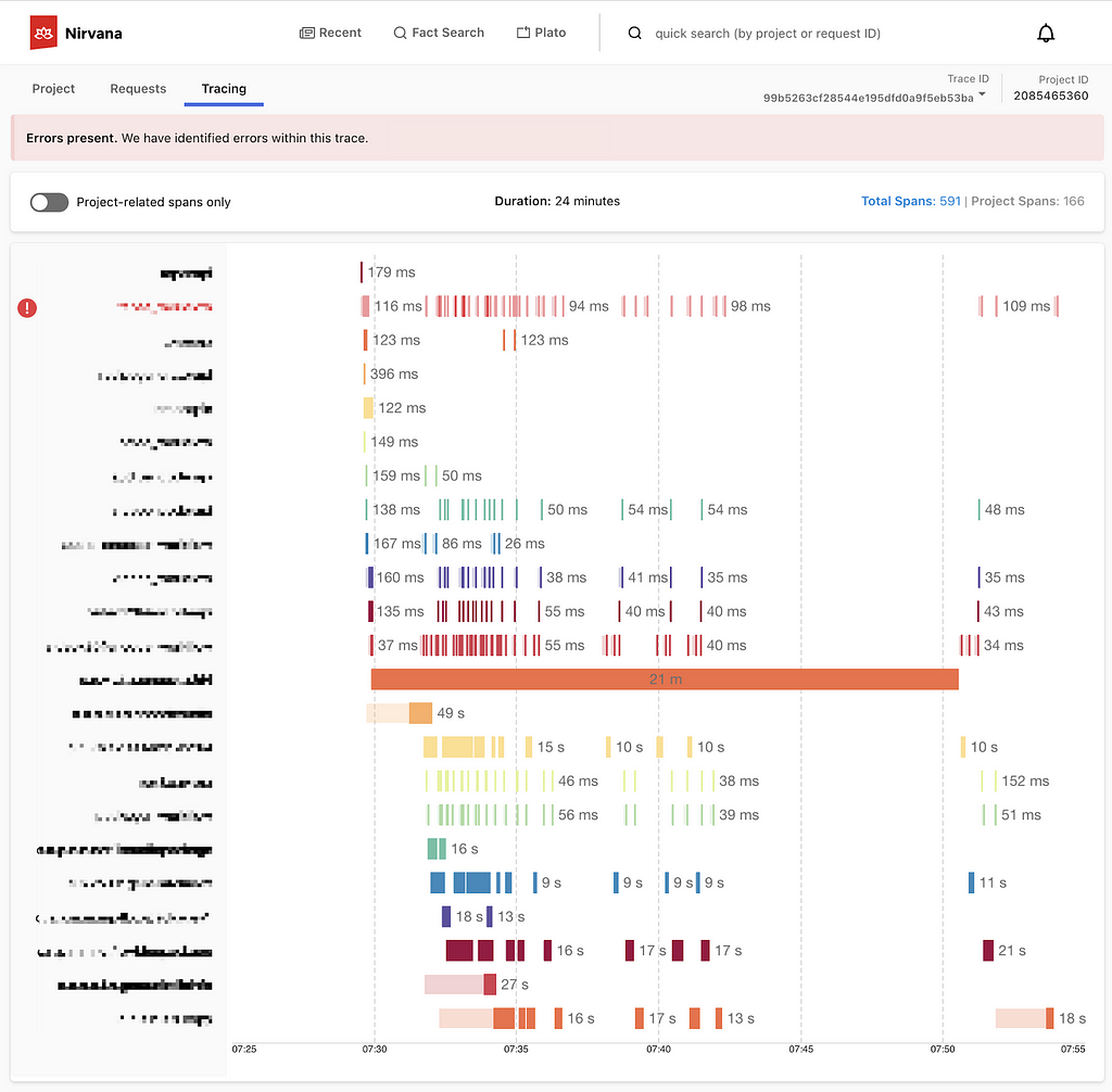
For engineers, instead of whodunit, the question is often “what failed and why?” When a problem occurs, we put on our detective hats and start our mystery-solving process by gathering evidence. The more complex a system, the more places to look for clues. An engineer can find herself digging through logs, poring over traces, and staring at dozens of dashboards.

All of these sources make it challenging to know where to begin and add to the time spent figuring out what went wrong. While this abundance of dashboards and information is by no means unique to Netflix, it certainly holds true within our microservices architecture. Each microservice may be easy to understand and debug individually, but what about when combined into a request that hits tens or hundreds of microservices? Searching for key evidence becomes like digging for a needle in a group of haystacks.

Example call graph in Edgar

In some cases, the question we’re answering is, “What’s happening right now??” and every second without resolution can carry a heavy cost. We want to resolve the problem as quickly as possible so our members can resume enjoying their favorite movies and shows. For teams building observability tools, the question is: how do we make understanding a system’s behavior fast and digestible? Quick to parse, and easy to pinpoint where something went wrong even if you aren’t deeply familiar with the inner workings and intricacies of that system? At Netflix, we’ve answered that question with a suite of observability tools. In an earlier blog post, we discussed Telltale, our health monitoring system. Telltale tells us when an application is unhealthy, but sometimes we need more fine-grained insight. We need to know why a specific request is failing and where. We built Edgar to ease this burden, by empowering our users to troubleshoot distributed systems efficiently with the help of a summarized presentation of request tracing, logs, analysis, and metadata.

What is Edgar?

Edgar is a self-service tool for troubleshooting distributed systems, built on a foundation of request tracing, with additional context layered on top. With request tracing and additional data from logs, events, metadata, and analysis, Edgar is able to show the flow of a request through our distributed system — what services were hit by a call, what information was passed from one service to the next, what happened inside that service, how long did it take, and what status was emitted — and highlight where an issue may have occurred. If you’re familiar with platforms like Zipkin or OpenTelemetry, this likely sounds familiar. But, there are a few substantial differences in how Edgar approaches its data and its users.

  • While Edgar is built on top of request tracing, it also uses the traces as the thread to tie additional context together. Deriving meaningful value from trace data alone can be challenging, as Cindy Sridharan articulated in this blog post. In addition to trace data, Edgar pulls in additional context from logs, events, and metadata, sifting through them to determine valuable and relevant information, so that Edgar can visually highlight where an error occurred and provide detailed context.
  • Edgar captures 100% of interesting traces, as opposed to sampling a small fixed percentage of traffic. This difference has substantial technological implications, from the classification of what’s interesting to transport to cost-effective storage (keep an eye out for later Netflix Tech Blog posts addressing these topics).
  • Edgar provides a powerful and consumable user experience to both engineers and non-engineers alike. If you embrace the cost and complexity of storing vast amounts of traces, you want to get the most value out of that cost. With Edgar, we’ve found that we can leverage that value by curating an experience for additional teams such as customer service operations, and we have embraced the challenge of building a product that makes trace data easy to access, easy to grok, and easy to gain insight by several user personas.

Tracing as a foundation

Logs, metrics, and traces are the three pillars of observability. Metrics communicate what’s happening on a macro scale, traces illustrate the ecosystem of an isolated request, and the logs provide a detail-rich snapshot into what happened within a service. These pillars have immense value and it is no surprise that the industry has invested heavily in building impressive dashboards and tooling around each. The downside is that we have so many dashboards. In one request hitting just ten services, there might be ten different analytics dashboards and ten different log stores. However, a request has its own unique trace identifier, which is a common thread tying all the pieces of this request together. The trace ID is typically generated at the first service that receives the request and then passed along from service to service as a header value. This makes the trace a great starting point to unify this data in a centralized location.

A trace is a set of segments representing each step of a single request throughout a system. Distributed tracing is the process of generating, transporting, storing, and retrieving traces in a distributed system. As a request flows between services, each distinct unit of work is documented as a span. A trace is made up of many spans, which are grouped together using a trace ID to form a single, end-to-end umbrella. A span:

  • Represents a unit of work, such as a network call from one service to another (a client/server relationship) or a purely internal action (e.g., starting and finishing a method).
  • Relates to other spans through a parent/child relationship.
  • Contains a set of key value pairs called tags, where service owners can attach helpful values such as urls, version numbers, regions, corresponding IDs, and errors. Tags can be associated with errors or warnings, which Edgar can display visually on a graph representation of the request.
  • Has a start time and an end time. Thanks to these timestamps, a user can quickly see how long the operation took.

The trace (along with its underlying spans) allows us to graphically represent the request chronologically.

Sample timeline view of a trace, based on Jaegar UI’s timeline view

Adding context to traces

With distributed tracing alone, Edgar is able to draw the path of a request as it flows through various systems. This centralized view is extremely helpful to determine which services were hit and when, but it lacks nuance. A tag might indicate there was an error but doesn’t fully answer the question of what happened. Adding logs to the picture can help a great deal. With logs, a user can see what the service itself had to say about what went wrong. If a data fetcher fails, the log can tell you what query it was running and what exact IDs or fields led to the failure. That alone might give an engineer the knowledge she needs to reproduce the issue. In Edgar, we parse the logs looking for error or warning values. We add these errors and warnings to our UI, highlighting them in our call graph and clearly associating them with a given service, to make it easy for users to view any errors we uncovered.

Example view of errors associated with a service, including an error parsed from a log

With the trace and additional context from logs illustrating the issue, one of the next questions may be how does this individual trace fit into the overall health and behavior of each service. Is this an anomaly or are we dealing with a pattern? To help answer this question, Edgar pulls in anomaly detection from a partner application, Telltale. Telltale provides Edgar with latency benchmarks that indicate if the individual trace’s latency is abnormal for this given service. A trace alone could tell you that a service took 500ms to respond, but it takes in-depth knowledge of a particular service’s typical behavior to make a determination if this response time is an outlier. Telltale’s anomaly analysis looks at historic behavior and can evaluate whether the latency experienced by this trace is anomalous. With this knowledge, Edgar can then visually warn that something happened in a service that caused its latency to fall outside of normal bounds.

Sample latency analysis

Edgar should reduce burden, not add to it

Presenting all of this data in one interface reduces the footwork of an engineer to uncover each source. However, discovery is only part of the path to resolution. With all the evidence presented and summarized by Edgar, an engineer may know what went wrong and where it went wrong. This is a huge step towards resolution, but not yet cause for celebration. The root cause may have been identified, but who owns the service in question? Many times, finding the right point of contact would require a jump into Slack or a company directory, which costs more time. In Edgar, we have integrated with our services to provide that information in-app alongside the details of a trace. For any service configured with an owner and support channel, Edgar provides a link to a service’s contact email and their Slack channel, smoothing the hand-off from one party to the next. If an engineer does need to pass an issue along to another team or person, Edgar’s request detail page contains all the context — the trace, logs, analysis — and is easily shareable, eliminating the need to write a detailed description or provide a cascade of links to communicate the issue.

Edgar’s request detail page

A key aspect of Edgar’s mission is to minimize the burden on both users and service owners. With all of its data sources, the sheer quantity of data could become overwhelming. It is essential for Edgar to maintain a prioritized interface, built to highlight errors and abnormalities to the user and assist users in taking the next step towards resolution. As our UI grows, it’s important to be discerning and judicious in how we handle new data sources, weaving them into our existing errors and warnings models to minimize disruption and to facilitate speedy understanding. We lean heavily on focus groups and user feedback to ensure a tight feedback loop so that Edgar can continue to meet our users’ needs as their services and use cases evolve.

As services evolve, they might change their log format or use new tags to indicate errors. We built an admin page to give our service owners that configurability and to decouple our product from in-depth service knowledge. Service owners can configure the essential details of their log stores, such as where their logs are located and what fields they use for trace IDs and span IDs. Knowing their trace and span IDs is what enables Edgar to correlate the traces and logs. Beyond that though, what are the idiosyncrasies of their logs? Some fields may be irrelevant or deprecated, and teams would like to hide them by default. Alternatively, some fields contain the most important information, and by promoting them in the Edgar UI, they are able to view these fields more quickly. This self-service configuration helps reduce the burden on service owners.

Initial log configuration in Edgar

Leveraging Edgar

In order for users to turn to Edgar in a situation when time is of the essence, users need to be able to trust Edgar. In particular, they need to be able to count on Edgar having data about their issue. Many approaches to distributed tracing involve setting a sample rate, such as 5%, and then only tracing that percentage of request traffic. Instead of sampling a fixed percentage, Edgar’s mission is to capture 100% of interesting requests. As a result, when an error happens, Edgar’s users can be confident they will be able to find it. That’s key to positioning Edgar as a reliable source. Edgar’s approach makes a commitment to have data about a given issue.

In addition to storing trace data for all requests, Edgar implemented a feature to collect additional details on-demand at a user’s discretion for a given criteria. With this fine-grained level of tracing turned on, Edgar captures request and response payloads as well as headers for requests matching the user’s criteria. This adds clarity to exactly what data is being passed from service to service through a request’s path. While this level of granularity is unsustainable for all request traffic, it is a robust tool in targeted use cases, especially for errors that prove challenging to reproduce.

As you can imagine, this comes with very real storage costs. While the Edgar team has done its best to manage these costs effectively and to optimize our storage, the cost is not insignificant. One way to strengthen our return on investment is by being a key tool throughout the software development lifecycle. Edgar is a crucial tool for operating and maintaining a production service, where reducing the time to recovery has direct customer impact. Engineers also rely on our tool throughout development and testing, and they use the Edgar request page to communicate issues across teams.

By providing our tool to multiple sets of users, we are able to leverage our cost more efficiently. Edgar has become not just a tool for engineers, but rather a tool for anyone who needs to troubleshoot a service at Netflix. In Edgar’s early days, as we strove to build valuable abstractions on top of trace data, the Edgar team first targeted streaming video use cases. We built a curated experience for streaming video, grouping requests into playback sessions, marked by starting and stopping playback for a given asset. We found this experience was powerful for customer service operations as well as engineering teams. Our team listened to customer service operations to understand which common issues caused an undue amount of support pain so that we could summarize these issues in our UI. This empowers customer service operations, as well as engineers, to quickly understand member issues with minimal digging. By logically grouping traces and summarizing the behavior at a higher level, trace data becomes extremely useful in answering questions like why a member didn’t receive 4k video for a certain title or why a member couldn’t watch certain content.

An example error viewing a playback session in Edgar

Extending Edgar for Studio

As the studio side of Netflix grew, we realized that our movie and show production support would benefit from a similar aggregation of user activity. Our movie and show production support might need to answer why someone from the production crew can’t log in or access their materials for a particular project. As we worked to serve this new user group, we sought to understand what issues our production support needed to answer most frequently and then tied together various data sources to answer those questions in Edgar.

The Edgar team built out an experience to meet this need, building another abstraction with trace data; this time, the focus was on troubleshooting production-related use cases and applications, rather than a streaming video session. Edgar provides our production support the ability to search for a given contractor, vendor, or member of production staff by their name or email. After finding the individual, Edgar reaches into numerous log stores for their user ID, and then pulls together their login history, role access change log, and recent traces emitted from production-related applications. Edgar scans through this data for errors and warnings and then presents those errors right at the front. Perhaps a vendor tried to login with the wrong password too many times, or they were assigned an incorrect role on a production. In this new domain, Edgar is solving the same multi-dashboarded problem by tying together information and pointing its users to the next step of resolution.

An example error for a production-related user

What Edgar is and is not

Edgar’s goal is not to be the be-all, end-all of tools or to be the One Tool to Rule Them All. Rather, our goal is to act as a concierge of troubleshooting — Edgar should quickly be able to guide users to an understanding of an issue, as well usher them to the next location, where they can remedy the problem. Let’s say a production vendor is unable to access materials for their production due to an incorrect role/permissions assignment, and this production vendor reaches out to support for assistance troubleshooting. When a support user searches for this vendor, Edgar should be able to indicate that this vendor recently had a role change and summarize what this role change is. Instead of being assigned to Dead To Me Season 2, they were assigned to Season 1! In this case, Edgar’s goal is to help a support user come to this conclusion and direct them quickly to the role management tool where this can be rectified, not to own the full circle of resolution.

Usage at Netflix

While Edgar was created around Netflix’s core streaming video use-case, it has since evolved to cover a wide array of applications. While Netflix streaming video is used by millions of members, some applications using Edgar may measure their volume in requests per minute, rather than requests per second, and may only have tens or hundreds of users rather than millions. While we started with a curated approach to solve a pain point for engineers and support working on streaming video, we found that this pain point is scale agnostic. Getting to the bottom of a problem is costly for all engineers, whether they are building a budget forecasting application used heavily by 30 people or a SVOD application used by millions.

Today, many applications and services at Netflix, covering a wide array of type and scale, publish trace data that is accessible in Edgar, and teams ranging from service owners to customer service operations rely on Edgar’s insights. From streaming to studio, Edgar leverages its wealth of knowledge to speed up troubleshooting across applications with the same fundamental approach of summarizing request tracing, logs, analysis, and metadata.

As you settle into your couch to watch a new episode of Unsolved Mysteries, you may still find yourself with more questions than answers. Why did the victim leave his house so abruptly? How did the suspect disappear into thin air? Hang on, how many people saw that UFO?? Unfortunately, Edgar can’t help you there (trust me, we’re disappointed too). But, if your relaxing evening is interrupted by a production outage, Edgar will be behind the scenes, helping Netflix engineers solve the mystery at hand.

Keeping services up and running allows Netflix to share stories with our members around the globe. Underneath every outage and failure, there is a story to tell, and powerful observability tooling is needed to tell it. If you are passionate about observability then come talk to us.


Edgar: Solving Mysteries Faster with Observability was originally published in Netflix TechBlog on Medium, where people are continuing the conversation by highlighting and responding to this story.