Tag Archives: Analytics

ETL orchestration using the Amazon Redshift Data API and AWS Step Functions with AWS SDK integration

Post Syndicated from Jason Pedreza original https://aws.amazon.com/blogs/big-data/etl-orchestration-using-the-amazon-redshift-data-api-and-aws-step-functions-with-aws-sdk-integration/

Extract, transform, and load (ETL) serverless orchestration architecture applications are becoming popular with many customers. These applications offers greater extensibility and simplicity, making it easier to maintain and simplify ETL pipelines. A primary benefit of this architecture is that we simplify an existing ETL pipeline with AWS Step Functions and directly call the Amazon Redshift Data API from the state machine. As a result, the complexity for the ETL pipeline is reduced.

As a data engineer or an application developer, you may want to interact with Amazon Redshift to load or query data with a simple API endpoint without having to manage persistent connections. The Amazon Redshift Data API allows you to interact with Amazon Redshift without having to configure JDBC or ODBC connections. This feature allows you to orchestrate serverless data processing workflows, design event-driven web applications, and run an ETL pipeline asynchronously to ingest and process data in Amazon Redshift, with the use of Step Functions to orchestrate the entire ETL or ELT workflow.

This post explains how to use Step Functions and the Amazon Redshift Data API to orchestrate the different steps in your ETL or ELT workflow and process data into an Amazon Redshift data warehouse.

AWS Lambda is typically used with Step Functions due to its flexible and scalable compute benefits. An ETL workflow has multiple steps, and the complexity may vary within each step. However, there is an alternative approach with AWS SDK service integrations, a feature of Step Functions. These integrations allow you to call over 200 AWS services’ API actions directly from your state machine. This approach is optimal for steps with relatively low complexity compared to using Lambda because you no longer have to maintain and test function code. Lambda functions have a maximum timeout of 15 minutes; if you need to wait for longer-running processes, Step Functions standard workflows allows a maximum runtime of 1 year.

You can replace steps that include a single process with a direct integration between Step Functions and AWS SDK service integrations without using Lambda. For example, if a step is only used to call a Lambda function that runs a SQL statement in Amazon Redshift, you may remove the Lambda function with a direct integration to the Amazon Redshift Data API’s SDK API action. You can also decouple Lambda functions with multiple actions into multiple steps. An implementation of this is available later in this post.

We created an example use case in the GitHub repo ETL Orchestration using Amazon Redshift Data API and AWS Step Functions that provides an AWS CloudFormation template for setup, SQL scripts, and a state machine definition. The state machine directly reads SQL scripts stored in your Amazon Simple Storage Service (Amazon S3) bucket, runs them in your Amazon Redshift cluster, and performs an ETL workflow. We don’t use Lambda in this use case.

Solution overview

In this scenario, we simplify an existing ETL pipeline that uses Lambda to call the Data API. AWS SDK service integrations with Step Functions allow you to directly call the Data API from the state machine, reducing the complexity in running the ETL pipeline.

The entire workflow performs the following steps:

  1. Set up the required database objects and generate a set of sample data to be processed.
  2. Run two dimension jobs that perform SCD1 and SCD2 dimension load, respectively.
  3. When both jobs have run successfully, the load job for the fact table runs.
  4. The state machine performs a validation to ensure the sales data was loaded successfully.

The following architecture diagram highlights the end-to-end solution:

We run the state machine via the Step Functions console, but you can run this solution in several ways:

You can deploy the solution with the provided CloudFormation template, which creates the following resources:

  • Database objects in the Amazon Redshift cluster:
    • Four stored procedures:
      • sp_setup_sales_data_pipeline() – Creates the tables and populates them with sample data
      • sp_load_dim_customer_address() – Runs the SCD1 process on customer_address records
      • sp_load_dim_item() – Runs the SCD2 process on item records
      • sp_load_fact_sales (p_run_date date) – Processes sales from all stores for a given day
    • Five Amazon Redshift tables:
      • customer
      • customer_address
      • date_dim
      • item
      • store_sales
  • The AWS Identity and Access Management (IAM) role StateMachineExecutionRole for Step Functions to allow the following permissions:
    • Federate to the Amazon Redshift cluster through getClusterCredentials permission avoiding password credentials
    • Run queries in the Amazon Redshift cluster through Data API calls
    • List and retrieve objects from Amazon S3
  • The Step Functions state machine RedshiftETLStepFunction, which contains the steps used to run the ETL workflow of the sample sales data pipeline

Prerequisites

As a prerequisite for deploying the solution, you need to set up an Amazon Redshift cluster and associate it with an IAM role. For more information, see Authorizing Amazon Redshift to access other AWS services on your behalf. If you don’t have a cluster provisioned in your AWS account, refer to Getting started with Amazon Redshift for instructions to set it up.

When the Amazon Redshift cluster is available, perform the following steps:

  1. Download and save the CloudFormation template to a local folder on your computer.
  2. Download and save the following SQL scripts to a local folder on your computer:
    1. sp_statements.sql – Contains the stored procedures including DDL and DML operations.
    2. validate_sql_statement.sql – Contains two validation queries you can run.
  3. Upload the SQL scripts to your S3 bucket. The bucket name is the designated S3 bucket specified in the ETLScriptS3Path input parameter.
  4. On the AWS CloudFormation console, choose Create stack with new resources and upload the template file you downloaded in the previous step (etl-orchestration-with-stepfunctions-and-redshift-data-api.yaml).
  5. Enter the required parameters and choose Next.
  6. Choose Next until you get to the Review page and select the acknowledgement check box.
  7. Choose Create stack.
  8. Wait until the stack deploys successfully.

When the stack is complete, you can view the outputs, as shown in the following screenshot:

Run the ETL orchestration

After you deploy the CloudFormation template, navigate to the stack detail page. On the Resources tab, choose the link for RedshiftETLStepFunction to be redirected to the Step Functions console.

The RedshiftETLStepFunction state machine runs automatically, as outlined in the following workflow:

  1. read_sp_statement and run_sp_deploy_redshift – Performs the following actions:
    1. Retrieves the sp_statements.sql from Amazon S3 to get the stored procedure.
    2. Passes the stored procedure to the batch-execute-statement API to run in the Amazon Redshift cluster.
    3. Sends back the identifier of the SQL statement to the state machine.
  2. wait_on_sp_deploy_redshift – Waits for at least 5 seconds.
  3. run_sp_deploy_redshift_status_check – Invokes the Data API’s describeStatement to get the status of the API call.
  4. is_run_sp_deploy_complete – Routes the next step of the ETL workflow depending on its status:
    1. FINISHED – Stored procedures are created in your Amazon Redshift cluster.
    2. FAILED – Go to the sales_data_pipeline_failure step and fail the ETL workflow.
    3. All other status – Go back to the wait_on_sp_deploy_redshift step to wait for the SQL statements to finish.
  5. setup_sales_data_pipeline – Performs the following steps:
    1. Initiates the setup stored procedure that was previously created in the Amazon Redshift cluster.
    2. Sends back the identifier of the SQL statement to the state machine.
  6. wait_on_setup_sales_data_pipeline – Waits for at least 5 seconds.
  7. setup_sales_data_pipeline_status_check – Invokes the Data API’s describeStatement to get the status of the API call.
  8. is_setup_sales_data_pipeline_complete – Routes the next step of the ETL workflow depending on its status:
    1. FINISHED – Created two dimension tables (customer_address and item) and one fact table (sales).
    2. FAILED – Go to the sales_data_pipeline_failure step and fail the ETL workflow.
    3. All other status – Go back to the wait_on_setup_sales_data_pipeline step to wait for the SQL statements to finish.
  9. run_sales_data_pipeline LoadItemTable and LoadCustomerAddressTable are two parallel workflows that Step Functions runs at the same time. The workflows run the stored procedures that were previously created. The stored procedure loads the data into the item and customer_address tables. All other steps in the parallel sessions follow the same concept as described previously. When both parallel workflows are complete, run_load_fact_sales runs.
  10. run_load_fact_sales – Inserts data into the store_sales table that was created in the initial stored procedure.
  11. Validation – When all the ETL steps are complete, the state machine reads a second SQL file from Amazon S3 (validate_sql_statement.sql) and runs the two SQL statements using the batch_execute_statement method.

The implementation of the ETL workflow is idempotent. If it fails, you can retry the job without any cleanup. For example, it recreates the stg_store_sales table each time, then deletes the target table store_sales with the data for the particular refresh date each time.

The following diagram illustrates the state machine workflow:

In this example, we use the task state resource arn:aws:states:::aws-sdk:redshiftdata:[apiAction] to call the corresponding Data API action. The following table summarizes the Data API actions and their corresponding AWS SDK integration API actions.

Amazon Redshift Data API Actions AWS SDK Integrations API Actions
BatchExecuteStatement batchExecuteStatement
ExecuteStatement executeStatement
DescribeStatement describeStatement
CancelStatement cancelStatement
GetStatementResult getStatementResult
DescribeTable describeTable
ListDatabases listDatabases
ListSchemas listSchemas
ListStatements listStatements
ListTables listTables

To use AWS SDK integrations, you specify the service name and API call, and, optionally, a service integration pattern. The AWS SDK action is always camel case, and parameter names are Pascal case. For example, you can use the Step Functions action batchExecuteStatement to run multiple SQL statements in a batch as a part of a single transaction on the Data API. The SQL statements can be SELECT, DML, DDL, COPY, and UNLOAD.

Validate the ETL orchestration

The entire ETL workflow takes approximately 1 minute to run. The following screenshot shows that the ETL workflow completed successfully.

When the entire sales data pipeline is complete, you may go through the entire execution event history, as shown in the following screenshot.

Schedule the ETL orchestration

After you validate the sales data pipeline, you may opt to run the data pipeline on a daily schedule. You can accomplish this with Amazon EventBridge.

  1. On the EventBridge console, create a rule to run the RedshiftETLStepFunction state machine daily.
  2. To invoke the RedshiftETLStepFunction state machine on a schedule, choose Schedule and define the appropriate frequency needed to run the sales data pipeline.
  3. Specify the target state machine as RedshiftETLStepFunction and choose Create.

You can confirm the schedule on the rule details page.

Clean up

Clean up the resources created by the CloudFormation template to avoid unnecessary cost to your AWS account. You can delete the CloudFormation stack by selecting the stack on the AWS CloudFormation console and choosing Delete. This action deletes all the resources it provisioned. If you manually updated a template-provisioned resource, you may see some issues during cleanup; you need to clean these up independently.

Limitations

The Data API and Step Functions AWS SDK integration offers a robust mechanism to build highly distributed ETL applications within minimal developer overhead. Consider the following limitations when using the Data API and Step Functions:

Conclusion

In this post, we demonstrated how to build an ETL orchestration using the Amazon Redshift Data API and Step Functions with AWS SDK integration.

To learn more about the Data API, see Using the Amazon Redshift Data API to interact with Amazon Redshift clusters and Using the Amazon Redshift Data API.


About the Authors

Jason Pedreza is an Analytics Specialist Solutions Architect at AWS with over 13 years of data warehousing experience. Prior to AWS, he built data warehouse solutions at Amazon.com. He specializes in Amazon Redshift and helps customers build scalable analytic solutions.

Bipin Pandey is a Data Architect at AWS. He loves to build data lake and analytics platforms for his customers. He is passionate about automating and simplifying customer problems with the use of cloud solutions.

David Zhang is an AWS Solutions Architect who helps customers design robust, scalable, and data-driven solutions across multiple industries. With a background in software development, David is an active leader and contributor to AWS open-source initiatives. He is passionate about solving real-world business problems and continuously strives to work from the customer’s perspective. Feel free to connect with him on LinkedIn.

Announcing the new Amazon QuickSight Community

Post Syndicated from Lillie Atkins original https://aws.amazon.com/blogs/big-data/announcing-the-new-amazon-quicksight-community/

On February 22, 2022, we launched our new Amazon QuickSight Community. Here you can ask and answer questions, network with and learn from other Business Intelligence (BI) users from across the globe, access learning content, and stay up to date with what’s new on Amazon QuickSight—all in one place!

In this post, we discuss some of the features of the QuickSight Community and show you how to sign up, start posting, create a profile and set up notifications.

Content on the Community

The QuickSight Community has three main sections:

  1. Question and Answer – A discussion forum where you can ask your QuickSight questions and get answers from community experts. You can also showcase your QuickSight expertise by sharing your knowledge with others.
  2. Learning Center – A hub for on-demand QuickSight content, including how-to videos workshop videos, articles, and additional educational resources.
  3. Announcements – Stay up-to-date on the latest QuickSight launches, blogs, feature demo videos, and monthly newsletters. We continuously update this section as new content related to QuickSight is added.

Join the QuickSight Community

This QuickSight Community does not require any login to search or browse existing content. You only need to create an account if you want to interact with the community (such as liking posts, replying to posts, and posting your own questions).

This is a public community, so be careful not to post any confidential or private information.

Sign up for the Community

To sign up, complete the following steps:

  1. On the QuickSight Community home page, choose Sign Up.
  2. You can either use your existing Amazon.com account, or create a new login.
  3. Read the Community guidelines.

You can now contribute to the Community. Welcome!

Post a question

You need to be logged in with an account to start asking questions. Before you post a question, search the recommended questions to make sure your question hasn’t already been answered.

To post a question, complete the following steps:

  1. On the Question and answer page, choose New Question.
  2. Enter the information to create your post, including a title and tag.
  3. Choose New Question.

Set up your profile

To view your profile and change the settings, complete the following steps:

  1. Choose your user icon at the top of the page and choose the person icon.
  2. Select the section you are interested in:
  3. If you chose Preferences, you can control security and notification preferences, and update your profile details.

Set up notifications

You can set up notification preferences to be alerted on a specific post, channel, or tag.

To set up notifications on a post, choose the post and then choose the notification icon to set your notification preferences.

To get notified on a specific channel, go to the channel (in this case the Question and answer channel) and choose the notification bell to set your notification preferences.

To get notified on a specific tag, complete the following steps:

  1. Choose the additional options icon.
  2. Choose Tags.
  3. Choose the tag you are interested in.
  4. Choose the notification icon and set your notification preferences.

Conclusion

In this post, we discussed the new Amazon QuickSight Community, and how you can sign up for it, create a post, edit your profile, and set up notifications. The QuickSight Community is a one-stop shop for all of your QuickSight learning needs, and a place to network with other BI users from around the globe. Start exploring today!


About the Authors

Lillie Atkins is a Product Manager for Amazon QuickSight, Amazon Web Service’s cloud-native, fully managed BI service.

Mia Heard is a Product Marketing Manager for Amazon QuickSight, AWS’ cloud-native, fully managed BI service.

Enhance resiliency with admission control in Amazon OpenSearch Service (successor to Amazon Elasticsearch Service)

Post Syndicated from Mital Awachat original https://aws.amazon.com/blogs/big-data/enhance-resiliency-with-admission-control-in-amazon-opensearch-service-successor-to-amazon-elasticsearch-service/

OpenSearch is a distributed, open-source search and analytics suite used for a broad set of use cases like real-time application monitoring, log analytics, and website search. Amazon OpenSearch Service (successor to Amazon Elasticsearch Service) is a managed service that makes it easy to secure, deploy, and operate OpenSearch clusters at scale. Amazon OpenSearch Service provides a broad range of cluster configurations to meet your use cases. In 2021, we released automated memory management under Auto-Tune. Auto-Tune is an adaptive resource management system in Amazon OpenSearch Service that continuously monitors incoming workloads and optimizes cluster resources to improve efficiency and performance.

Today, we’re excited to announce the release of admission control for Auto-Tune. Admission control in Amazon OpenSearch Service enhances the overall resiliency of OpenSearch clusters by limiting new incoming requests early, at the REST layer, when a node is stressed. This mechanism prevents potential node failures and cascading effects on the cluster.

Overview of admission control

Admission control acts like a lever to regulate traffic based on cluster state. It does so by allocating tokens for each OpenSearch request, based on predicted resource usage. It releases the tokens when the process is complete. After all the tokens are acquired, any additional requests to the node are throttled with a “too many requests” exception until tokens are available again for request processing. In some cases, an operator can utilize admission control to completely shut down traffic and prevent frequent node drops until a certain condition is met, such as shards being assigned.

Admission control is a gatekeeper for nodes, limiting the number of requests processed to a node based on its current capacity.

Admission control prevents Amazon OpenSearch Service domains from getting overloaded both by steady increases and surges in traffic. It’s resource-aware, so it tunes the cluster based on incoming request cost (content length of request payload), and the point-in-time state of the node (overall Java Virtual Machine (JVM)). This awareness enables real-time, state-based admission control on the node. Admission control for Auto-Tune is available in all AWS Regions on domains running OpenSearch 1.0, or Elasticsearch 6.7 and higher.

By default, admission control throttles _search and _bulk requests when JVM memory pressure and request size thresholds are breached.

  • JVM memory pressure threshold
    Admission control keeps track of the current state of JVM memory pressure and throttles incoming requests based on a preconfigured JVM memory pressure threshold. When the threshold is breached, all configured _search and _bulk requests are throttled until the memory is released on the node and memory pressure is below the threshold.
  • Request size threshold
    The size of a particular request is determined by it’s content-length. Admission control keeps track of in-flight requests and allocates tokens to every request based on this content length. Admission control then throttles incoming requests based on memory occupancy when the aggregated size of in-flight requests breaches the pre-configured threshold. All new _search and _bulk requests are throttled until the in-flight requests complete, relinquishing the quota to be occupied by new requests.

The following diagram illustrates this process.

How Auto-Tune works

Auto-Tune uses performance and usage metrics from OpenSearch clusters to suggest memory-related configuration changes to improve cluster speed and stability. You can view its recommendations on the Amazon OpenSearch Service console. Admission control is a non-disruptive change, meaning that the changes can be applied without rebooting the node.

Admission control’s predefined request size threshold of 10% satisfies most use cases. However, Auto-Tune can now dynamically increase and decrease the default threshold, typically between 5–15%, based on the amount of JVM that is currently occupied on the system. Request size threshold auto-tuning is enabled by default when you enable Auto-Tune.

Auto-Tune currently doesn’t tune the JVM memory pressure threshold.

Monitoring admission control

Amazon OpenSearch Service sends two Auto-Tune metrics to Amazon CloudWatch: AutoTuneSucceeded and AutoTuneFailed. Each metric contains a sub-category called AutotuningType, which indicates the specific type of change in question. Admission control adds a new type called ADMISSION_CONTROL_TUNING.

To view it, choose ES/OpenSearchService on the Metrics page on the CloudWatch console.

Then choose AutotuningType, ClientId, DomainName, TargetId.

For AutotuningType, filter by ADMISSION_CONTROL_TUNING.

Conclusion

Admission control introduces request-based rejections of _search and _bulk requests when there are too many requests or JVM usage is high, breaching thresholds. This prevents the nodes from running into cascading effects of failures arising due to the following:

  • Surges in traffic – Sudden surges or spikes in request traffic, leading to quick buildup in usage across the nodes
  • Skew in shard distribution – Improper distribution of shards, leading to hot spots and bottlenecks, affecting the overall performance
  • Slow Nodes – Entire data node starts to slow down due to degraded hardware such as disk, network volumes, or software bugs

Stay tuned for more exciting updates about Amazon OpenSearch Service and features.


About the Authors

Mital Awachat is an SDE-II working on Amazon OpenSearch Service at Amazon Web Services.

Saurabh Singh is a Senior Software Engineer working on AWS OpenSearch at Amazon Web Services. He is passionate about solving problems related to data retrieval and large-scale distributed systems. He is an active contributor to OpenSearch.

Ranjith Ramachandra is an Engineering Manager working on Amazon OpenSearch Service at Amazon Web Services.

How Cynamics built a high-scale, near-real-time, streaming AI inference system using AWS

Post Syndicated from Aviv Yehezkel original https://aws.amazon.com/blogs/big-data/how-cynamics-built-a-high-scale-near-real-time-streaming-ai-inference-system-using-aws/

This post is co-authored by Dr. Yehezkel Aviv, Co-Founder and CTO of Cynamics and Sapir Kraus, Head of Engineering at Cynamics.

Cynamics provides a new paradigm of cybersecurity — predicting attacks long before they hit by collecting small network samples (less than 1%), inferring from them how the full network (100%) behaves, and predicting threats using unique AI breakthroughs. The sample approach allows Cynamics to be generic, agnostic, and work for any client’s network architecture, no matter how messy the mix between legacy, private, and public clouds. Furthermore, the solution is scalable and provides full cover to the client’s network, no matter how large it is in volume and size. Moreover, because any network gateway (physical or virtual, legacy or cloud) supports one of the standard sampling protocols and APIs, Cynamics doesn’t require any installation of appliances nor agents, as well as no network changes and modifications, and the onboarding usually takes less than an hour.

In the crowded cybersecurity market, Cynamics is the first-ever solution based on small network samples, which has been considered a hard and unsolved challenge in academia (our academic paper “Network anomaly detection using transfer learning based on auto-encoders loss normalization” was recently presented in ACM CCS AISec 2021) and industry to this day.

The problem Cynamics faced

Early in the process, with the growth of our customer base, we were required to seamlessly support the increased scale and network throughput by our unique AI algorithms. We faced a few different challenges:

  • How can we perform near-real-time analysis on our streaming clients’ incoming data into our AI inference system to predict threats and attacks?
  • How can we seamlessly auto scale our solution to be cost-efficient with no impact on the platform ingestion rate?
  • Because many of our customers are from the public sector, how can we do this while supporting both AWS commercial and government environments (GovCloud)?

This post shows how we used AWS managed services and in particular Amazon Kinesis Data Streams and Amazon EMR to build a near-real-time streaming AI inference system serving hundreds of production customers in both AWS commercial and government environments, while seamlessly auto scaling.

Overview of solution

The following diagram illustrates our solution architecture:

To provide a cost-efficient, highly available solution that scales easily with user growth, while having no impact on near-real-time performance, we turned to Amazon EMR.

We currently process over 50 million records per day, which translates to just over 5 billion flows, and keeps growing on a daily basis. Using Amazon EMR along with Kinesis Data Streams provided the scalability we needed to achieve inference times of just a few seconds.

Although this technology was new to us, we minimized our learning curve by turning to the available guides from AWS for best practices on scale, partitioning, and resource management.

Workflow

Our workflow contains the following steps:

  1. Flow samples are sent by the client’s network devices directly to the Cynamics cloud. A network flow (or connection) is a set of packets with the same five-tuple ID: source-IP-address, destination-IP-address, source-port, destination-port, and protocol.
  2. The samples are analyzed by Network Load Balancers, which forward them into an auto scaling group of stateless flow transformers running on Graviton-powered Amazon Elastic Compute Cloud (Amazon EC2) instances. With Graviton-based processors in the flow transformers, we reduced our operational costs by over 30%.
  3. The flows are transformed to the Cynamics data format and enriched with additional information from Cynamics’ databases and in-house sources such as IP resolutions, intelligence, and reputation.

The following figures show the network scale for a single flow transformer machine over a week. The first figure illustrates incoming network packets for a single flow transformer machine.

The following shows outcoming network packets for a single flow transformer machine.

The following shows incoming network bytes for a single flow transformer machine.

The following shows outcoming network bytes for a single flow transformer machine.

  1. The flows are sent using Kinesis Data Streams to the real-time analysis engine.
  2. The Amazon EMR-based real-time engine consumes records in a few seconds batches using Yarn/Spark. The sampling rate of each client is dynamically tuned according to its throughput to ensure a fixed incoming data rate for all clients. We achieved this using Amazon EMR Managed Scaling with a custom policy (available with Amazon EMR versions 5.30.1 and later), which allows us to scale EMR nodes in or out based on Amazon CloudWatch metrics, with two different rules for scale-out and scale-in. The metric we created is based on the Amazon EMR running time, because our real-time AI threat detection runs on a sliding window interval of a few seconds.
    1. The scale-out policy tracks the average running time over a period of 10 minutes, and scales the EMR nodes if it’s longer than 95% of the required interval. This allows us to prevent processing delays.
    2. Similarly, the scale-in policy uses the same metric but measures the average over a 30-minute period, and scales the cluster accordingly. This enables us to optimize cluster costs and reduce the number of EMR nodes in off-hours.
  3. To optimize and seamlessly scale our AI inference calls, these were made available through an ALB and another auto scaling group of servers (AI model-service).
  4. We use Amazon DynamoDB as a fast and highly available states table.

The following figure shows the number of records processed by the Kinesis data stream over a single day.

The following shows the Kinesis data streams records rate per minute.

AI predictions and threat detections are sent to continued processing and alerting, and are saved in Amazon DocumentDB (with MongoDB compatibility).

Conclusion

With the approach described in this post, Cynamics has been providing threat prediction based on near-real-time analysis of its unique AI algorithms for a constantly growing customer base in a seamless and automatically scalable way. Since first implementing the solution, we’ve managed to easily and linearly scale our architecture, and were able to further optimize our costs by transitioning to Graviton-based processors in the flow transformers, which reduced over 30% of our flow transformers costs.

We’re considering the following next steps:

  • An automatic machine learning lifecycle using an Amazon SageMaker Studio pipeline, which includes the following steps:
  • Additional cost reduction by moving the EMR instances to be Graviton-based as well, which should yield an additional 20% reduction.

About the Authors

Dr. Yehezkel Aviv is the co-founder and CTO of Cynamics, leading the company innovation and technology. Aviv holds a PhD in Computer Science from the Technion, specializing in cybersecurity, AI, and ML.

Sapir Kraus is Head of Engineering at Cynamics, where his core focus is managing the software development lifecycle. His responsibilities also include software architecture and providing technical guidance to team members. Outside of work, he enjoys roasting coffee and barbecuing.

Omer Haim is a Startup Solutions Architect at Amazon Web Services. He helps startups with their cloud journey, and is passionate about containers and ML. In his spare time, Omer likes to travel, and occasionally game with his son.

How to evaluate the benefits of AQUA for your Amazon Redshift workloads

Post Syndicated from Dinesh Kumar original https://aws.amazon.com/blogs/big-data/how-to-evaluate-the-benefits-of-aqua-for-your-amazon-redshift-workloads/

Amazon Redshift is the cloud data warehouse of choice for tens of thousands of customers, who use it to analyze exabytes of data to gain business insights. Customers have been asking us for better performance at scale as the volume, variety, velocity, and veracity of their data grows. We have added several features to Amazon Redshift that enable you to get up to three times better price performance with Amazon Redshift than other cloud data warehouses.

In addition, we launched AQUA (Advanced Query Accelerator) for Amazon Redshift to help you cost-effectively run analytics at the new scale of data. AQUA is a distributed and hardware-accelerated cache that enables Amazon Redshift to run an order of magnitude faster than other enterprise cloud data warehouses by automatically boosting certain types of queries. AQUA uses AWS-designed processors with AWS Nitro chips adapted to speed up data encryption and compression, and custom analytics processors, implemented in FPGAs, to accelerate operations such as scans, filtering, and aggregation. AQUA is available with the RA3.16xlarge, RA3.4xlarge, and RA3.xlplus nodes at no additional charge and requires no code changes. You can enable AQUA for your existing Amazon Redshift RA3 clusters or launch a new AQUA-enabled RA3 cluster via the AWS Management Console, API, or AWS Command Line Interface (AWS CLI). To learn more about AQUA, see Working with AQUA (Advanced Query Accelerator).

This post walks you through steps to quantify expected benefits from AQUA for Amazon Redshift for your workloads. We cover the methodology used for testing AQUA and share the scripts, a sample dataset, and queries so you can test AQUA in your own environment. We have published scripts on GitHub (along with a README file), which you need as you follow the steps in this post. Download all scripts to your working directory from where you intend to connect to your Redshift clusters.

Solution overview

At a high-level, the AQUA test process involves the following steps:

  1. Create a test cluster to evaluate AQUA and make sure that AQUA is turned on. For instructions, see Working with AQUA (Advanced Query Accelerator).
  2. Analyze your workload for AQUA and capture eligible queries. To learn more about the types of queries accelerated by AQUA, refer to When does Amazon Redshift use AQUA to run queries?
  3. Run the workload with AQUA activated and deactivated on your test cluster.
  4. Compare performance results.

This approach is a straightforward yet practical way to measure the performance gain you can expect to get for your workload by turning on AQUA.

With the exception of one workload parsing and analyzing script (aqua_capture_query.sh), you can run the rest of the scripts on a test cluster. We recommend using a test cluster to minimize the impact to your production cluster.

Create a test cluster

Create a snapshot from a production cluster that has read-heavy workloads and restore it as test cluster.

Analyze your workload and capture eligible queries

Run aqua_capture_query.sh on the production cluster to determine the queries suitable for acceleration by AQUA. We recommend choosing workloads with SELECT queries that use LIKE or SIMILAR TO functions in the WHERE clause and scan, filter, and aggregate large datasets. aqua_capture_query.sh scans the query history on your production cluster and captures queries that AQUA can accelerate.

The script runtime may exceed several minutes depending on the selected time interval (analyze_starttime and analyze_endtime), size of the cluster, and workload complexity. We suggest restricting the script runtime by limiting the time interval to the lesser of your workload runtime or 3 hours. Alternately, you can evaluate AQUA using the Amazon Reviews sample dataset, which we demonstrate later in this post.

aqua_capture_query.sh saves an output file named aqua_eligible_queries to your working directory and contains a subset of most suitable AQUA-eligible queries.

The following is a sample output by the script:

select count(*) from amazon_reviews where product_title SIMILAR TO '%lap%' group by star_rating ORDER BY star_rating desc;
select count(*) from amazon_reviews where product_title ilike '%e%|%E%' or customer_ID like '3%__%45__3';

If your workload history doesn’t have enough AQUA-eligible queries, the script reports no eligible queries found. If this happens, run the script with different date/time parameters. If you still don’t see any queries, you can try using the sample dataset and queries provided in this post. For more information about AQUA-eligible queries, refer to When does Amazon Redshift use AQUA to run queries?

Run the workload on your test cluster

Run aqua_execute_query.sh on your test cluster. The script runs the captured queries on your cluster repeatedly to get consistent performance by reducing the impact of runtime difference due to environmental factors with AQUA activated and deactivated. The script records the start date/time and end date/time to a file named workload_datetime.txt in your working directory.

Compare performance results

When aqua_execute_query.sh script is complete, run aqua_perf_compare.sh, which generates a CSV file named aqua_benefit in your working directory. The following table summarizes the sample output.

Query ID Amazon Redshift with AQUA turned on Query ID Amazon Redshift with AQUA turned off Runtime in seconds with AQUA turned on Runtime in seconds with AQUA turned off Speedup
(Column C/Column B)
1153194 1153370 2.7 59.4 22.0
1153214 1153456 22.8 104.9 4.6
334629 334631 1.66643 35.8 22.25
334850 334672 1.71297 26.9 15.7
334984 334998 1.85051 26.9 14.5
334830 334793 6.47884 87.2 13.4
334828 334740 6.6974 87.1 13

This table shows the query identifiers and runtime of the queries with AQUA activated and deactivated. You can compare the benefits offered by AQUA by reviewing the speedup column.

Example use case with the Amazon Reviews dataset

To test AQUA with the Amazon Reviews sample dataset, perform the following steps:

  1. Create a two-node RA3.4xlarge cluster by issuing the following command:
    aws redshift create-cluster --cluster-identifier test-amazon-reviews --node-type ra3.4xlarge --number-of-nodes 2 --master-username adminuser --master-user-password <xxpasswordxx> --aqua-configuration-status enabled

  2. Create a test database on our Amazon Redshift cluster by issuing the following command:
    CREATE DATABASE TestDB;

  3. Load the table with the Amazon Reviews dataset by running the script load_amazon_sentiments_data.sql.
  4. Run a few AQUA-eligible queries (similar to the following) multiple times with and without AQUA activated using the script execute_test_queries.sh:
    select count(*) from amazon_reviews WHERE product_title SIMILAR TO '%lap%' or product_title SIMILAR TO '%hope%' or product_title SIMILAR TO '%nice%' or product_title SIMILAR TO '%soa%';

More evaluation queries are available on the GitHub repo.

  1. Run aqua_perf_compare.sh on the test cluster.

The following table shows that AQUA accelerated the queries 5–22 times faster.

Query ID Amazon Redshift with AQUA turned on Query ID Amazon Redshift with AQUA turned off Runtime in seconds with AQUA turned on Runtime in seconds with AQUA turned off Speedup
(Column C/Column B)
364202 364217 2.33411 51.56207 22.09073
334984 334998 1.85051 26.9 14.5
334830 334793 6.47884 87.2 13.4
334828 334740 6.6974 87.1 13

Summary

This post provides a straightforward yet practical way to measure the performance gain you can expect to get for your workload by turning on AQUA. You can use the scripts provided and test with your own dataset and queries, or use the sample dataset and queries to determine AQUA’s impact.

We continue to invest and launch new capabilities like AQUA for Amazon Redshift to make sure Amazon Redshift continues to improve as your data warehouse needs grow. For AQUA, we continue to add hardware acceleration for more SQL operators, functions, predicates, data types, and file formats so more scans, filters, and aggregations can be pushed down to AQUA. Pushdowns to AQUA remain transparent so Amazon Redshift decides when to push queries down to AQUA to take advantage of hardware acceleration. And when queries don’t get pushed down to AQUA, they continue to run on Amazon Redshift as before.

We invite you to test AQUA for yourself and share the findings.


About the Authors

Dinesh Kumar is a Database Engineer at AWS focusing on Amazon AQUA. He works with customers to build highly scalable data warehouse and high performant database solutions. Outside work, he enjoys gardening and spending time with his family.

Manan Goel is a Product Go-To-Market Leader for AWS Analytics Services including Amazon Redshift & AQUA at AWS. He has more than 25 years of experience and is well versed with databases, data warehousing, business intelligence, and analytics. Manan holds a MBA from Duke University and a BS in Electronics & Communications engineering.

Enable users to ask questions about data using natural language within your applications by embedding Amazon QuickSight Q

Post Syndicated from Deepak Murthy original https://aws.amazon.com/blogs/big-data/enable-users-to-ask-questions-about-data-using-natural-language-within-your-applications-by-embedding-amazon-quicksight-q/

Amazon QuickSight Q is a new machine learning-based capability in Amazon QuickSight that enables users to ask business questions in natural language and receive answers with relevant visualizations instantly to gain insights from data. QuickSight Q doesn’t depend on prebuilt dashboards or reports to answer questions, which removes the need for business intelligence (BI) teams to create or update dashboards every time a new business question arises. Users can ask questions and receive visual answers in seconds directly from within QuickSight or from web applications and portals. In this post, we look at how you can embed Q in your web applications or portals.

Solution overview

You can now embed Q in your application without any custom development. Q is a fully managed cloud-native BI offering that you can easily embed without requiring expertise within your team to develop and maintain this capability. You can easily democratize your data and scale your insights to a growing user base, while ensuring you only pay for usage with Q’s unique pay-per-question pricing model.

Applications can authenticate users with any identity provider of choice (such as Active Directory, Amazon Cognito, or any SAML-based federated SSO provider that your organization uses) and act on behalf of the user to get access to the Q question bar. This means that every user receives a secure, personalized question answering experience while requiring no user-facing QuickSight-specific authentication. This enables a novel experience to provide insights within your application with minimal upfront work and allows you to focus on your core application functionality! QuickSight Q embedding is available in QuickSight Enterprise Edition and Q-supported Regions.

To facilitate an easy embedding experience, AWS has also launched the Amazon QuickSight Embedding SDK (JavaScript) and a rich set of Q-specific functionalities. The QuickSight Embedding SDK lets you efficiently integrate Q in your application pages, set a default topic, enable topic selection, set themes, and control Q search bar behavior. This helps you roll out Q to your users faster.

To embed Q in your application, you must complete the following high-level steps:

  1. Set up permissions to generate embedded Q URLs.
  2. Generate a URL with the authentication code attached.
  3. Embed the Q search bar URL.

Set up permissions to generate embedded Q URLs

In this step, you set up permissions for your backend application or web server to embed the Q search bar. This task requires administrative access to AWS Identity and Access Management (IAM). Each user who accesses the Q search bar assumes a role that gives them QuickSight permissions to retrieve a Q-embedded URL.

To make this possible, create an IAM role in your AWS account. Associate an IAM policy with the role to provide permissions to any user who assumes it. The IAM role needs to provide permissions to retrieve embedding URLs for a specific user pool. With the help of the wildcard character *, you can grant the permissions to generate a URL for all users in a specific namespace. Or you can grant permissions to generate a URL for a subset of users in specific namespaces. For this, you add quicksight:GenerateEmbedUrlForRegisteredUser.

The following sample policy provides these permissions:

{
    "Version": "2012-10-17",
    "Statement": [
        {
            "Effect": "Allow",
            "Action": [
                "quicksight:GenerateEmbedUrlForRegisteredUser"
            ],
            "Resource": "arn:partition:quicksight:region:accountId:user/namespace/userName"
        }
    ]
}

Also, if you’re creating first-time users who will be QuickSight readers, make sure to add the quicksight:RegisterUser permission in the policy.

The following sample policy provides permission to retrieve an embedding URL for first-time users who will be QuickSight readers:

{
    "Version": "2012-10-17",
    "Statement": [
        {
            "Action": "quicksight:RegisterUser",
            "Resource": "*",
            "Effect": "Allow"
        },
        {
            "Effect": "Allow",
            "Action": [
              "quicksight:GenerateEmbedUrlForRegisteredUser"
            ],
            "Resource": [
              "arn:partition:quicksight:region:accountId:user/namespace/userName"
            ]
        }
    ]
}

Finally, your application’s IAM identity must have a trust policy associated with it to allow access to the role that you just created. This means that when a user accesses your application, your application assumes the role on the user’s behalf and provisions the user in QuickSight.

The following example uses a role called embedding_quicksight_q_search_bar_role, which has the sample policy preceding as its resource:

{
    "Version": "2012-10-17",
    "Statement": {
        "Effect": "Allow",
        "Action": "sts:AssumeRole",
        "Resource": "arn:aws:iam::11112222333:role/embedding_quicksight_q_search_bar_role"
    }
}

Generate a URL with the authentication code attached

In this step, you authenticate your user and get the embeddable Q topic URL on your application server. If you plan to embed the Q bar for IAM or QuickSight identity types, share the Q topic with the users. When a user accesses your app, the app assumes the IAM role of the user. If that user is new, the app adds the user to QuickSight, then passes an identifier as the unique role session ID.

These steps make sure that each viewer of the Q topic is uniquely provisioned in QuickSight. It also enforces per-user settings, such as the row-level security and dynamic defaults for parameters.

The following example code performs the IAM authentication on the user’s behalf. This code runs on your app server:

import com.amazonaws.auth.AWSCredentials;
import com.amazonaws.auth.BasicAWSCredentials;
import com.amazonaws.auth.AWSCredentialsProvider;
import com.amazonaws.regions.Regions;
import com.amazonaws.services.quicksight.AmazonQuickSight;
import com.amazonaws.services.quicksight.AmazonQuickSightClientBuilder;
import com.amazonaws.services.quicksight.model.GenerateEmbedUrlForRegisteredUserRequest;
import com.amazonaws.services.quicksight.model.GenerateEmbedUrlForRegisteredUserResult;
import com.amazonaws.services.quicksight.model.RegisteredUserEmbeddingExperienceConfiguration;
import com.amazonaws.services.quicksight.model.RegisteredUserQSearchBarEmbeddingConfiguration;

/**
 * Class to call QuickSight AWS SDK to get url for embedding the Q search bar.
 */
public class RegisteredUserQSearchBarEmbeddingConfiguration {

    private final AmazonQuickSight quickSightClient;

    public RegisteredUserQSearchBarEmbeddingConfiguration() {
        this.quickSightClient = AmazonQuickSightClientBuilder
                .standard()
                .withRegion(Regions.US_EAST_1.getName())
                .withCredentials(new AWSCredentialsProvider() {
                                     @Override
                                     public AWSCredentials getCredentials() {
                                         // provide actual IAM access key and secret key here
                                         return new BasicAWSCredentials("access-key", "secret-key");
                                     }

                                     @Override
                                     public void refresh() {}
                                 }
                )
                .build();
    }

    public String getQuicksightEmbedUrl(
            final String accountId, // AWS Account ID
            final String topicId, // Topic ID to embed
            final String userArn // Registered user arn to use for embedding. Refer to Get Embed Url section in developer portal to find how to get user arn for a QuickSight user.
    ) throws Exception {
        final RegisteredUserEmbeddingExperienceConfiguration experienceConfiguration = new RegisteredUserEmbeddingExperienceConfiguration()
                .withQSearchBar(new RegisteredUserQSearchBarEmbeddingConfiguration().withInitialTopicId(topicId));
        final GenerateEmbedUrlForRegisteredUserRequest generateEmbedUrlForRegisteredUserRequest = new GenerateEmbedUrlForRegisteredUserRequest();
        generateEmbedUrlForRegisteredUserRequest.setAwsAccountId(accountId);
        generateEmbedUrlForRegisteredUserRequest.setUserArn(userArn);
        generateEmbedUrlForRegisteredUserRequest.setExperienceConfiguration(QSearchBar);

        final GenerateEmbedUrlForRegisteredUserResult generateEmbedUrlForRegisteredUserResult = quickSightClient.generateEmbedUrlForRegisteredUser(generateEmbedUrlForRegisteredUserRequest);

        return generateEmbedUrlForRegisteredUserResult.getEmbedUrl();
    }
}

To generate the URL that you can embed in your app, call the GenerateEmbedUrlForRegisteredUser API operation. This URL is valid for 5 minutes, and the resulting session is valid for up to 10 hours. You can configure the session validity by setting the sessionLifetimeinMinutes parameter for GenerateEmbedURL APIs. The API operation provides the URL with an auth_code value that enables a single-sign on session. The following code shows an example response from generate-embed-url-for-registered-user:

//The URL returned is over 900 characters. For this example, we've shortened the string for
//readability and added ellipsis to indicate that it's incomplete.
{
 "Status": "200",
 "EmbedUrl": "https: //dashboards.example.com/embed/620bef10822743fab329fb3751187d2d...",
 "RequestId": "7bee030e-f191-45c4-97fe-d9faf0e03713"
} 

Embed the Q search bar URL

In this step, you embed the Q search bar URL in your website or application page. You can do this with the QuickSight Embedding SDK, which allows you to do the following:

  • Place the Q search bar on an HTML page
  • Pass parameters into the Q search bar
  • Handle error states with messages that are customized to your application

Embed the Q search bar in your webpage by using the QuickSight Embedding SDK or by adding this URL into an iFrame. If you set a fixed height and width number (in pixels), QuickSight uses those and doesn’t change your visual as your window resizes. If you set a relative percent height and width, QuickSight provides a responsive layout that is modified as your window size changes. When you use the QuickSight Embedding SDK, the Q search bar on your page is dynamically resized based on the state. By using the QuickSight Embedding SDK, you can also control parameters within the Q search bar and receive callbacks in terms of page load completion and errors.

The following example code shows how to use the generated URL. This code is generated on your app server:

<!DOCTYPE html>
         <html>
     
         <head>
             <title>QuickSight Q Search Bar Embedding</title>
             <script src="https://unpkg.com/[email protected]/dist/quicksight-embedding-js-sdk.min.js"></script>
             <script type="text/javascript">
                 var session
     
                 function onError(payload) {
                     console.log("Do something when the session fails loading");
                 }
     
                 function onOpen() {
                     console.log("Do something when the Q search bar opens");
                 }
     
                 function onClose() {
                     console.log("Do something when the Q search bar closes");
                 }
     
                 function embedQSearchBar() {
                     var containerDiv = document.getElementById("embeddingContainer");
                     var options = {
                         url: "https://us-east-1.quicksight.aws.amazon.com/sn/dashboards/dashboardId?isauthcode=true&identityprovider=quicksight&code=authcode", // replace this dummy url with the one generated via embedding API
                         container: containerDiv,
                         width: "1000px",
                         locale: "en-US",
                         qSearchBarOptions: {
                             expandCallback: onOpen,
                             collapseCallback: onClose,
                             iconDisabled: false,
                             topicNameDisabled: false, 
                             themeId: 'theme12345',
                             allowTopicSelection: true
                         }
                     };
                     session = QuickSightEmbedding.embedQSearchBar(options);
                     session.on("error", onError);
                 }
     
                 function onCountryChange(obj) {
                     session.setParameters({country: obj.value});
                 }
             </script>
         </head>
     
         <body onload="embedQSearchBar()">
             <div id="embeddingContainer"></div>
         </body>
     
         </html>

For this example to work, make sure to use the QuickSight Embedding SDK to load the embedded dashboard on your website using JavaScript. You can get the SDK in the following ways:

  • Download the QuickSight Embedding SDK from GitHub. This repository is maintained by a group of QuickSight developers.
  • Download the latest QuickSight Embedding SDK version from npmjs.com.
  • If you use npm for JavaScript dependencies, download and install it by running the following command:
    npm install amazon-quicksight-embedding-sdk

The following screenshot is an example of the embedded Q question bar and a QuickSight dashboard to support natural language questions and analysis of pharmaceutical clinical trial data. You can try out this topic and other such topics in an embedded application demo.

Summary

Enterprises can empower users to ask questions about data in plain English within their applications by embedding the QuickSight Q question bar. Embedding Q into your application is straightforward and requires no custom development from your team.

Get started with a free trial of QuickSight Q.


About the Authors

Deepak Murthy is a Senior Product Manager for Amazon QuickSight, AWS’s cloud-native, fully managed BI service. Deepak started his career with Staples, developing enterprise data warehouse solutions. Later, he was the architect of data warehouse and analytics solutions at Wells Fargo, AMC, and Blackhawk Network. Deepak is excited about the potential of self-service analytics and improving data accessibility by enabling new natural language interactions with data, and looks forward to helping customers leverage these latest analytics innovations.

Rob Foley is a Software Development Engineer for Amazon QuickSight, AWS’s cloud-native, fully managed BI service. Rob began his career with AWS, and has been a member of the QuickSight team for over 1.5 years. He has development experience in a breadth of services and stacks, primarily having worked on data-centric applications like Q.

Build a data sharing workflow with AWS Lake Formation for your data mesh

Post Syndicated from Jan Michael Go Tan original https://aws.amazon.com/blogs/big-data/build-a-data-sharing-workflow-with-aws-lake-formation-for-your-data-mesh/

A key benefit of a data mesh architecture is allowing different lines of business (LOBs) and organizational units to operate independently and offer their data as a product. This model not only allows organizations to scale, but also gives the end-to-end ownership of maintaining the product to data producers that are the domain experts of the data. This ownership entails maintaining the data pipelines, debugging ETL scripts, fixing data quality issues, and keeping the catalog entries up to date as the dataset evolves over time.

On the consumer side, teams can search the central catalog for relevant data products and request access. Access to the data is done via the data sharing feature in AWS Lake Formation. As the amount of data products grow and potentially more sensitive information is stored in an organization’s data lake, it’s important that the process and mechanism to request and grant access to specific data products are done in a scalable and secure manner.

This post describes how to build a workflow engine that automates the data sharing process while including a separate approval mechanism for data products that are tagged as sensitive (for example, containing PII data). Both the workflow and approval mechanism are customizable and should be adapted to adhere to your company’s internal processes. In addition, we include an optional workflow UI to demonstrate how to integrate with the workflow engine. The UI is just one example of how the interaction works. In a typical large enterprise, you can also use ticketing systems to automatically trigger both the workflow and the approval process.

Solution overview

A typical data mesh architecture for analytics in AWS contains one central account that collates all the different data products from multiple producer accounts. Consumers can search the available data products in a single location. Sharing data products to consumers doesn’t actually make a separate copy, but instead just creates a pointer to the catalog item. This means any updates that producers make to their products are automatically reflected in the central account as well as in all the consumer accounts.

Building on top of this foundation, the solution contains several components, as depicted in the following diagram:

The central account includes the following components:

  • AWS Glue – Used for Data Catalog purposes.
  • AWS Lake Formation – Used to secure access to the data as well as provide the data sharing capabilities that enable the data mesh architecture.
  • AWS Step Functions – The actual workflow is defined as a state machine. You can customize this to adhere to your organization’s approval requirements.
  • AWS Amplify – The workflow UI uses the Amplify framework to secure access. It also uses Amplify to host the React-based application. On the backend, the Amplify framework creates two Amazon Cognito components to support the security requirements:
    • User pools – Provide a user directory functionality.
    • Identity pools – Provide federated sign-in capabilities using Amazon Cognito user pools as the location of the user details. The identity pools vend temporary credentials so the workflow UI can access AWS Glue and Step Functions APIs.
  • AWS Lambda – Contains the application logic orchestrated by the Step Functions state machine. It also provides the necessary application logic when a producer approves or denies a request for access.
  • Amazon API Gateway – Provides the API for producers to accept and deny requests.

The producer account contains the following components:

The consumer account contains the following components:

  • AWS Glue – Used for Data Catalog purposes.
  • AWS Lake Formation – After the data has been made available, consumers can grant access to its own users via Lake Formation.
  • AWS Resource Access Manager (AWS RAM) – If the grantee account is in the same organization as the grantor account, the shared resource is available immediately to the grantee. If the grantee account is not in the same organization, AWS RAM sends an invitation to the grantee account to accept or reject the resource grant. For more details about Lake Formation cross-account access, see Cross-Account Access: How It Works.

The solution is split into multiple steps:

  1. Deploy the central account backend, including the workflow engine and its associated components.
  2. Deploy the backend for the producer accounts. You can repeat this step multiple times depending on the number of producer accounts that you’re onboarding into the workflow engine.
  3. Deploy the optional workflow UI in the central account to interact with the central account backend.

Workflow overview

The following diagram illustrates the workflow. In this particular example, the state machine checks if the table or database (depending on what is being shared) has the pii_flag parameter and if it’s set to TRUE. If both conditions are valid, it sends an approval request to the producer’s SNS topic. Otherwise, it automatically shares the product to the requesting consumer.

This workflow is the core of the solution, and can be customized to fit your organization’s approval process. In addition, you can add custom parameters to databases, tables, or even columns to attach extra metadata to support the workflow logic.

Prerequisites

The following are the deployment requirements:

You can clone the workflow UI and AWS CDK scripts from the GitHub repository.

Deploy the central account backend

To deploy the backend for the central account, go to the root of the project after cloning the GitHub repository and enter the following code:

yarn deploy-central --profile <PROFILE_OF_CENTRAL_ACCOUNT>

This deploys the following:

  • IAM roles used by the Lambda functions and Step Functions state machine
  • Lambda functions
  • The Step Functions state machine (the workflow itself)
  • An API Gateway

When the deployment is complete, it generates a JSON file in the src/cfn-output.json location. This file is used by the UI deployment script to generate a scoped-down IAM policy and workflow UI application to locate the state machine that was created by the AWS CDK script.

The actual AWS CDK scripts for the central account deployment are in infra/central/. This also includes the Lambda functions (in the infra/central/functions/ folder) that are used by both the state machine and the API Gateway.

Lake Formation permissions

The following table contains the minimum required permissions that the central account data lake administrator needs to grant to the respective IAM roles for the backend to have access to the AWS Glue Data Catalog.

Role Permission Grantable
WorkflowLambdaTableDetails
  • Database: DESCRIBE
  • Tables: DESCRIBE
N/A
WorkflowLambdaShareCatalog
  • Tables: SELECT, DESCRIBE
  • Tables: SELECT, DESCRIBE

Workflow catalog parameters

The workflow uses the following catalog parameters to provide its functionality.

Catalog Type Parameter Name Description
Database data_owner (Required) The account ID of the producer account that owns the data products.
Database data_owner_name A readable friendly name that identifies the producer in the UI.
Database pii_flag A flag (true/false) that determines whether the data product requires approval (based on the example workflow).
Column pii_flag A flag (true/false) that determines whether the data product requires approval (based on the example workflow). This is only applicable if requesting table-level access.

You can use UpdateDatabase and UpdateTable to add parameters to database and column-level granularity, respectively. Alternatively, you can use the CLI for AWS Glue to add the relevant parameters.

Use the AWS CLI to run the following command to check the current parameters in your database:

aws glue get-database --name <DATABASE_NAME> --profile <PROFILE_OF_CENTRAL_ACCOUNT>

You get the following response:

{
  "Database": {
    "Name": "<DATABASE_NAME>",
    "CreateTime": "<CREATION_TIME>",
    "CreateTableDefaultPermissions": [],
    "CatalogId": "<CATALOG_ID>"
  }
}

To update the database with the parameters indicated in the preceding table, we first create the input JSON file, which contains the parameters that we want to update the database with. For example, see the following code:

{
  "Name": "<DATABASE_NAME>",
  "Parameters": {
    "data_owner": "<AWS_ACCOUNT_ID_OF_OWNER>",
    "data_owner_name": "<AWS_ACCOUNT_NAME_OF_OWNER>",
    "pii_flag": "true"
  }
}

Run the following command to update the Data Catalog:

aws glue update-database --name <DATABASE_NAME> --database-input file://<FILE_NAME>.json --profile <PROFILE_OF_CENTRAL_ACCOUNT>

Deploy the producer account backend

To deploy the backend for your producer accounts, go to the root of the project and run the following command:

yarn deploy-producer --profile <PROFILE_OF_PRODUCER_ACCOUNT> --parameters centralMeshAccountId=<central_account_account_id>

This deploys the following:

  • An SNS topic where approval requests get published.
  • The ProducerWorkflowRole IAM role with a trust relationship to the central account. This role allows Amazon SNS publish to the previously created SNS topic.

You can run this deployment script multiple times, each time pointing to a different producer account that you want to participate in the workflow.

To receive notification emails, subscribe your email in the SNS topic that the deployment script created. For example, our topic is called DataLakeSharingApproval. To get the full ARN, you can either go to the Amazon Simple Notification Service console or run the following command to list all the topics and get the ARN for DataLakeSharingApproval:

aws sns list-topics --profile <PROFILE_OF_PRODUCER_ACCOUNT>

After you have the ARN, you can subscribe your email by running the following command:

aws sns subscribe --topic-arn <TOPIC_ARN> --protocol email --notification-endpoint <EMAIL_ADDRESS> --profile <PROFILE_OF_PRODUCER_ACCOUNT>

You then receive a confirmation email via the email address that you subscribed. Choose Confirm subscription to receive notifications from this SNS topic.

Deploy the workflow UI

The workflow UI is designed to be deployed in the central account where the central data catalog is located.

To start the deployment, enter the following command:

yarn deploy-ui

This deploys the following:

  • Amazon Cognito user pool and identity pool
  • React-based application to interact with the catalog and request data access

The deployment command prompts you for the following information:

  • Project information – Use the default values.
  • AWS authentication – Use your profile for the central account. Amplify uses this profile to deploy the backend resources.

UI authentication – Use the default configuration and your username. Choose No, I am done when asked to configure advanced settings.

  • UI hosting – Use hosting with the Amplify console and choose manual deployment.

The script gives a summary of what is deployed. Entering Y triggers the resources to be deployed in the backend. The prompt looks similar to the following screenshot:

When the deployment is complete, the remaining prompt is for the initial user information such as user name and email. A temporary password is automatically generated and sent to the email provided. The user is required to change the password after the first login.

The deployment script grants IAM permissions to the user via an inline policy attached to the Amazon Cognito authenticated IAM role:

{
   "Version":"2012-10-17",
   "Statement":[
      {
         "Effect":"Allow",
         "Action":[
            "glue:GetDatabase",
            "glue:GetTables",
            "glue:GetDatabases",
            "glue:GetTable"
         ],
         "Resource":"*"
      },
      {
         "Effect":"Allow",
         "Action":[
            "states:ListExecutions",
            "states:StartExecution"
         ],
         "Resource":[
"arn:aws:states:<REGION>:<AWS_ACCOUNT_ID>:stateMachine:<STATE_MACHINE_NAME>"
]
      },
      {
         "Effect":"Allow",
         "Action":[
             "states:DescribeExecution"
         ],
         "Resource":[
"arn:aws:states:<REGION>:<AWS_ACCOUNT_ID>:execution:<STATE_MACHINE_NAME>:*"
]
      }


   ]
}

The last remaining step is to grant Lake Formation permissions (DESCRIBE for both databases and tables) to the authenticated IAM role associated with the Amazon Cognito identity pool. You can find the IAM role by running the following command:

cat amplify/team-provider-info.json

The IAM role name is in the AuthRoleName property under the awscloudformation key. After you grant the required permissions, you can use the URL provided in your browser to open the workflow UI.

Your temporary password is emailed to you so you can complete the initial login, after which you’re asked to change your password.

The first page after logging in is the list of databases that consumers can access.

Choose Request Access to see the database details and the list of tables.

Choose Request Per Table Access and see more details at the table level.

Going back in the previous page, we request database-level access by entering the consumer account ID that receives the share request.

Because this database has been tagged with a pii_flag, the workflow needs to send an approval request to the product owner. To receive this approval request email, the product owner’s email needs to be subscribed to the DataLakeSharingApproval SNS topic in the product account. The details should look similar to the following screenshot:

The email looks similar to the following screenshot:

The product owner chooses the Approve link to trigger the Step Functions state machine to continue running and share the catalog item to the consumer account.

For this example, the consumer account is not part of an organization, so the admin of the consumer account has to go to AWS RAM and accept the invitation.

After the resource share is accepted, the shared database appears in the consumer account’s catalog.

Clean up

If you no longer need to use this solution, use the provided cleanup scripts to remove the deployed resources.

Producer account

To remove the deployed resources in producer accounts, run the following command for each producer account that you deployed in:

yarn clean-producer --profile <PROFILE_OF_PRODUCER_ACCOUNT>

Central account

Run the following command to remove the workflow backend in the central account:

yarn clean-central --profile <PROFILE_OF_CENTRAL_ACCOUNT>

Workflow UI

The cleanup script for the workflow UI relies on an Amplify CLI command to initiate the teardown of the deployed resources. Additionally, you can use a custom script to remove the inline policy in the authenticated IAM role used by Amazon Cognito so that Amplify can fully clean up all the deployed resources. Run the following command to trigger the cleanup:

yarn clean-ui

This command doesn’t require the profile parameter because it uses the existing Amplify configuration to infer where the resources are deployed and which profile was used.

Conclusion

This post demonstrated how to build a workflow engine to automate an organization’s approval process to gain access to data products with varying degrees of sensitivity. Using a workflow engine enables data sharing in a self-service manner while codifying your organization’s internal processes to be able to safely scale as more data products and teams get onboarded.

The provided workflow UI demonstrated one possible integration scenario. Other possible integration scenarios include integration with your organization’s ticketing system to trigger the workflow as well as receive and respond to approval requests, or integration with business chat applications to further shorten the approval cycle.

Lastly, a high degree of customization is possible with the demonstrated approach. Organizations have complete control over the workflow, how data product sensitivity levels are defined, what gets auto-approved and what needs further approvals, the hierarchy of approvals (such as a single approver or multiple approvers), and how the approvals get delivered and acted upon. You can take advantage of this flexibility to automate your company’s processes to help them safely accelerate towards being a data-driven organization.


About the Author

Jan Michael Go Tan is a Principal Solutions Architect for Amazon Web Services. He helps customers design scalable and innovative solutions with the AWS Cloud.

Extract ServiceNow data using AWS Glue Studio in an Amazon S3 data lake and analyze using Amazon Athena

Post Syndicated from Navnit Shukla original https://aws.amazon.com/blogs/big-data/extract-servicenow-data-using-aws-glue-studio-in-an-amazon-s3-data-lake-and-analyze-using-amazon-athena/

Many different cloud-based software as a service (SaaS) offerings are available in AWS. ServiceNow is one of the common cloud-based workflow automation platforms widely used by AWS customers. In the past few years, we saw a lot of customers who wanted to extract and integrate data from IT service management (ITSM) tools like ServiceNow for various use cases:

  • Generate insight from data – When you combine ServiceNow data with data from other services like CRM (such as Salesforce) or Martech data (such as Amazon Pinpoint) to generate better insights (e.g., building complete customer 360 view).
  • Archive data for future business or regulatory requirements – You can archive the data in raw form in your data lake to work on future use cases or just keep it to satisfy regulatory requirements such as auditing.
  • Improve performance by decoupling reporting or machine learning use cases from ITSM – When you move your ITSM reporting from ServiceNow to an Amazon Simple Storage Service (Amazon S3) data lake, there is no performance impact on your ServiceNow instance.
  • Data democratization – You can extract the data and put it into a data lake so it can be available to other business users and units to explore and use.

Many customers have been building modern data architectures on AWS, which includes building data lakes on Amazon S3 and using broad and deep AWS analytics and an AI/ML services to extract meaningful information from data by combining data from different data sources.

In this post, we provide a step-by-step guide to bring data from ServiceNow to an S3 data lake using AWS Glue Studio and analyze the data with Amazon Athena.

Solution overview

In this solution, ServiceNow data is being extracted through AWS Glue using a Marketplace connector. AWS Glue provides built-in support for the most commonly used data stores (such as Amazon Redshift, Amazon Aurora, Microsoft SQL Server, MySQL, MongoDB, and PostgreSQL) using JDBC connections. AWS Glue also allows you to use custom JDBC drivers in your extract, transform, and load (ETL) jobs. For data stores that are not natively supported, such as SaaS applications, you can use connectors and stored in Amazon S3. The data is cataloged in the AWS Glue Data Catalog, and we use Athena to query the data.

AWS Glue is a serverless data integration service that makes it easy to discover, prepare, and combine data for analytics, machine learning (ML), and application development. AWS Glue provides all the capabilities needed for data integration so you can start analyzing your data and put it to use in minutes instead of months.

Amazon Athena is an interactive query service that makes it easy to analyze data in Amazon S3 using standard SQL. Athena is serverless, so there is no infrastructure to manage, and you pay only for the queries that you run.

ServiceNow is a cloud-based software platform for ITSM that helps to automate IT business management. It’s designed based on ITIL guidelines to provide service orientation for tasks, activities, and processes.

The following diagram illustrates our solution architecture.
aws glue blog

To implement the solution, we complete the following high-level steps:

  1. Subscribe to the AWS Glue Connector Marketplace for ServiceNow from AWS Marketplace.
  2. Create a connection in AWS Glue Studio.
  3. Create an AWS Identity and Access Management (IAM) role for AWS Glue.
  4. Configure and run an AWS Glue job that uses the connection.
  5. Run the query against the data lake (Amazon S3) using Athena.

Prerequisites

For this walkthrough, you should have the following:

  • An AWS account.
  • A ServiceNow account. To follow along with this post, you can sign up for a developer account, which is pre-populated with sample records in many of the ServiceNow objects.
  • ServiceNow connection properties credentials stored in AWS Secrets Manager. On the Secrets Manager console, create a new secret (select Other type of secrets) with a key-value pair for each property, for example:
    • Username – ServiceNow Instance account user name (for example, admin)
    • Password – ServiceNow Instance account password
    • Instance – ServiceNow instance name without https and .service-now.com

Copy the secret name to use when configuring the connection in AWS Glue Studio.

Subscribe to the AWS Glue Marketplace Connector for ServiceNow

To connect, we use the AWS Glue Marketplace Connector for ServiceNow. You need to subscribe to the connector from AWS Marketplace.

The AWS Glue Marketplace Connector for ServiceNow is provided by third-party independent software vendor (ISV) listed on AWS Marketplace. Associated subscription fees and AWS usage fees apply once subscribed.

To use the connector in AWS Glue, you need to activate the subscribed connector in AWS Glue Studio. The activation process creates a connector object and connection in your AWS account.

  1. On the AWS Glue console, choose AWS Glue Studio.
  2. Choose Connectors.
  3. Choose Marketplace.
  4. Search for the CData AWS Glue Connector for ServiceNow.


After you subscribe to the connector, a new config tab appears on the AWS Marketplace connector page.

  1. Review the pricing and other relevant information.
  2. Choose Continue to Subscribe.
  3. Choose Accept Terms.

After you subscribe to the connector, the next steps are to configure it.

  1. Retain the default selections for Delivery Method and Software Version to use the latest connector software version.
  2. Choose Continue to Launch.

  1. Choose Usage Instructions.


A pop-up appears with a hyperlink to activate the connector with AWS Glue Studio.

  1. Choose this link to start configuring the connection to your ServiceNow account in AWS Glue Studio.

Create a connection in AWS Glue Studio

Create a connection in AWS Glue Studio with the following steps:

  1. For Name, enter a unique name for your ServiceNow connection.
  2. For Connection credential type, choose username_password.
  3. For AWS Secret, choose the Secrets Manager secret you created as a prerequisite.

Don’t provide any additional details in the optional Credentials section because it retrieves the value from Secrets Manager.

  1. Choose Create connection and activate connector to finish creating the connection.

You should now be able to view the ServiceNow connector you subscribed to and its associated connection.

Create an IAM role for AWS Glue

The next step is to create an IAM role with the necessary permissions for the AWS Glue job. The name of the role must start with the string AWSGlueServiceRole for AWS Glue Studio to use it correctly. You need to grant your IAM role permissions that AWS Glue can assume when calling other services on your behalf. For more information, see Create an IAM Role for AWS Glue.

Attach the following AWS managed policies to the role:

{
    "Version": "2012-10-17",
    "Statement": [
        {
            "Effect": "Allow",
            "Action": [
                "secretsmanager:GetResourcePolicy",
                "secretsmanager:GetSecretValue",
                "secretsmanager:DescribeSecret",
                "secretsmanager:ListSecretVersionIds"
            ],
            "Resource": [
                "{secret name arn}"
            ]
        }
    ]
}

For more information about permissions, see Review IAM permissions needed for the AWS Glue Studio user.

Configure and run the AWS Glue job

After you configure your connection, you can create and run an AWS Glue job.

Create a job that uses the connection

To create a job, complete the following steps:

  1. In AWS Glue Studio, choose Connectors.
  2. Select the connection you created.
  3. Choose Create job.


The visual job editor appears. A new source node, derived from the connection, is displayed on the job graph. In the node details panel on the right, the Data source properties tab is selected for user input.

Configure the source node properties

You can configure the access options for your connection to the data source on the Data source properties tab. For this post, we provide a simple walkthrough. Refer to the AWS Glue Studio User Guide for more information.

  1. On the Source menu, choose CData AWS Glue Connector for ServiceNow.

  1. On the Data source properties – Connector tab, make sure the source node for your connector is selected.

The Connection field is populated automatically with the name of the connection associated with the marketplace connector.

  1. Enter either a source table name or a query to use to retrieve data from the data source. For this post, we enter the table name incident.

  1. On the Transform menu, choose Apply Mapping.
  2. In a Node Property Tab, Select Node Parents CData AWS Glue Connector for ServiceNow.
  3. As we are connecting to an external data source; when you first look into Transform and Output schema tab; you won’t find the schema extracted from the source.
  4. In order for you to retrieve schema, Go to Data Preview tab, click on Start data preview session and select the IAM role you have created for this job.
  5. Once the Data preview is done, go to Data Source section and click on Use datapreview schema.
  6. Go to Transform and Check all the columns where Data Type showing as NULL.

  1. On the Target menu, choose Amazon S3.
  2. On the Data target properties – S3 tab, for Format, choose Parquet.
  3. For Compression Type, choose GZIP.
  4. For S3 Target Location, enter the Amazon S3 location to store the data.
  5. For Data Catalog update options, select Create a table in the Data Catalog and on subsequent runs, keep existing schema and add new partitions.
  6. For Database, enter sampledb.
  7. For Table name, enter incident.

Edit, save, and run the job

Edit the job by adding and editing the nodes in the job graph. See Editing ETL jobs in AWS Glue Studio for more information.

After you edit the job, enter the job properties.

  1. Choose the Job details tab above the visual graph editor.
  2. For Name, enter a job name.
  3. For IAM Role, choose an IAM role with the necessary permissions, as described previously.
  4. For Type, choose Spark.
  5. For Glue version, choose Glue 3.0 – Supports spark 3.1, Scala 2, Python 3.
  6. For Language, choose Python 3.
  7. Worker type : G.1X
  8. Requested number of workers: 2
  9. Number of retries: 1
  10. Job timeout (minutes): 3
  11. Use the default values for the other parameters.

For more information about job parameters, see Defining Job Properties for Spark Jobs.

12. After you save the job, choose Run to run the job.

Note – Running the Glue Job incur cost. You can learn more about AWS Glue Pricing here.

To view the generated script for the job, choose the Script tab at the top of the visual editor. The Job runs tab shows the job run history for the job. For more information about job run details, see View information for recent job runs.

Query against the data lake using Athena

After the job is complete, you can query the data in Athena.

  1. On the Athena console, choose the sampledb database.

You can view the newly created table called incident.

  1. Choose the options icon (three vertical dots) and choose Preview table to view the data.

Now let’s perform some analyses.

  1. Find all the incident tickets that are escalated by running the following query:
    SELECT task_effective_number FROM "sampledb"."incident" 
    where escalation = 2;

  1. Find ticket count with priority:
    SELECT priority, count(distinct task_effective_number)  FROM "sampledb"."incident"
    group by priority
    order by priority asc

Conclusion

In this post, we demonstrated how you can use an AWS Glue Studio connector to connect from ServiceNow and bring data into your data lake for further use cases.

AWS Glue provides built-in support for the most commonly used data stores (such as Amazon Redshift, Amazon Aurora, Microsoft SQL Server, MySQL, MongoDB, and PostgreSQL) using JDBC connections. AWS Glue also allows you to use custom JDBC drivers in your extract, transform, and load (ETL) jobs. For data stores that are not natively supported, such as SaaS applications, you can use connectors.

To learn more, refer to the AWS Glue Studio ConnectorAWS Glue Studio User Guide and Athena User Guide.


About the Authors

Navnit Shukla is AWS Specialist Solution Architect in Analytics. He is passionate about helping customers uncover insights from their data. He builds solutions to help organizations make data-driven decisions.

Srikanth Sopirala is a Principal Solutions Architect at AWS. He is a seasoned leader with over 20 years of experience, who is passionate about helping customers build scalable data and analytic solutions to gain timely insights and make critical business decisions. In his spare time, he enjoys reading, spending time with his family, and road biking.

Naresh Gautam is a Principal Solutions Architect at AWS. His role is helping customers architect highly available, high-performance, and cost-effective data analytics solutions to empower customers with data-driven decision-making. In his free time, he enjoys meditation and cooking.

Amazon Redshift at AWS re:Invent 2021 recap

Post Syndicated from Sunaina Abdul Salah original https://aws.amazon.com/blogs/big-data/amazon-redshift-at-aws-reinvent-2021-recap/

The annual AWS re:Invent learning conference is an exciting time full of new product and program launches. At the first re:Invent conference in 2012, AWS announced Amazon Redshift. Since then, tens of thousands of customers have started using Amazon Redshift as their preferred cloud data warehouse. At re:Invent 2021, AWS announced several new Amazon Redshift features that bring easy analytics for everyone while continuing to increase performance and help you break through data silos to analyze all the data in your data warehouse. With re:Invent packed with information and new announcements, it’s easy to miss the best of the updates in Amazon Redshift. In this post, we summarize these announcements, along with resources for you to get more details.

AWS takes analytics serverless

Adam Selipsky took the re:Invent keynote stage on November 29, 2021, for the first time as AWS CEO, announcing a string of innovations along the theme of pathfinders. He shared the story about Florence Nightingale, a pathfinder and data geek who had a passion for statistics, who collected and analyzed data on sanitation impact on mortality rates to mobilize the army at the time to approve new hygiene standards and restructure health efforts. The theme set the stage for the AWS modern data strategy, which enables everyone in the organization to find patterns in data and mobilize their business with data with the right tools for the right job. Selipsky’s announcement of serverless options for four AWS Analytics services, including Amazon Redshift, emphasized the growing need to be able to run complex analytics without touching infrastructure or managing capacity for your applications. Watch Adam Selipsky’s keynote announcement of AWS Analytics services with new serverless options (00:52).

Amazon Redshift: Under the hood

This year, VP of AWS Machine Learning Services Swami Sivasubramanian expanded his keynote to include the entire data and machine learning (ML) journey for all workloads and data types. In addition to mentioning the new serverless option announcement for Amazon Redshift in preview, he dove under the hood of Amazon Redshift to explore core innovations since its inception in 2012 that drove the service to become a best-in-class, petabyte-scale data warehouse for tens of thousands of customers. Sivasubramanian touched on features that enable Amazon Redshift to power large workloads with top-notch performance, including RA3 instances, AQUA (Advanced Query Accelerator), materialized views, short query acceleration, and automatic workload management. He also elaborated on how Amazon Redshift ML uses SQL to make ML predictions from your data warehouse. Neeraja Rentachintala then took you through a demo set in a gaming environment to outline the value of Amazon Redshift Serverless and Amazon QuickSight Q.

Reinvent your business for the future with AWS Analytics

Rahul Pathak, VP of AWS Analytics Services, talked in detail about how you can put your data to work and transform your businesses through end-to-end AWS Analytics services that help you modernize, unify, and innovate. He talked about how customers like Zynga, Schneider Electric, Magellan Rx, Jobcase, and Nasdaq are benefitting from Amazon Redshift with innovations in performance as data volumes grow. He elaborated on how Amazon Redshift helps you analyze all your data with AWS service integration, and touched upon the quest to make analytics easy for everyone with the introduction of the new Query Editor v2, Amazon Redshift Serverless, and data sharing capabilities. Watch the session to gain a deeper understanding of AWS Analytics services.

What’s new with Amazon Redshift, featuring Schneider Electric

This session is a must-watch for every existing and new Amazon Redshift customer to get a full understanding of the breadth and depth of features that Amazon Redshift offers along the dimensions of easy analytics for everyone, analyze all your data, and performance at scale. Eugene Kawamoto, Director of Amazon Redshift Product, goes into detail about all the new launches in 2021, tracing the architectural evolution of Amazon Redshift to the new serverless option. He explores how Amazon Redshift integrates with other popular AWS services to help you break through data silos, analyze all your data, and derive value from this data.

Democratizing data for self-service analytics and ML

Access to all your data for fast analytics at scale is foundational for 360-degree projects involving data engineers, database developers, data analysts, data scientists, business intelligence professionals, and the line of business. In this session, Greg Khairallah and Shruti Worlikar, leaders in the AWS Analytics GTM organization, team up with our customer Jobcase, represented by Senior Scientist Clay Martin, to show how easy-to-use ML can help your organization imagine new products or services, transform your customer experiences, streamline your business operations, and improve your decision-making. A secure, integrated platform that’s easy to use and supports nonproprietary data formats can improve collaboration through data sharing and also improve customer responsiveness.

Introducing Amazon Redshift Serverless

Following the announcements in the keynotes, this session takes you through the new serverless option on Amazon Redshift, which enables you to get started in seconds and run data warehousing and analytics workloads at scale without worrying about data warehouse management. In this session, learn from Yan Leshinsky, VP of Amazon Redshift, and Neeraja Rentachintala, Principal Product Manager for Amazon Redshift, on how Amazon Redshift Serverless automatically provisions data warehouse capacity and intelligently scales the underlying resources to deliver consistently high performance and simplified operations for even the most demanding and volatile workloads.

Introduction to AWS Data Exchange for Amazon Redshift

We’ve talked about Amazon Redshift Serverless several times, but there were some exciting announcements from the service leading into re:Invent. We launched AWS Data Exchange for Amazon Redshift, which allows you to combine third-party data found on AWS Data Exchange with your own data from your Amazon Redshift cloud data warehouse, requiring no ETL and accelerating time to value. This provides a powerful enhancement to the strong data-sharing capabilities in Amazon Redshift to share secure, live data across Regions, accounts, and organizations. In this session, product managers Neeraja Rentachintala and Ryan Waldorf walk through the value of this integration and how to access and analyze a provider’s data with data providers, which enables licensing this access to their Amazon Redshift cloud data warehouses. Alex Bohl, Director of Data Innovation from Mathematica, joins them in this session to provide a real-world example.

Additional sessions

In addition to these sessions, the hands-on-workshops and chalk talks were packed with customers looking to learn more about Amazon Redshift’s capabilities in ML with Redshift ML, concurrency scaling, and much more. These sessions were not recorded.

Get started with Amazon Redshift

Learn more about the latest and greatest of what Amazon Redshift offers you, and explore the following resources for more information about new releases:


About the Author

Sunaina Abdul Salah leads product marketing for Amazon Redshift.

Use AnalyticsIQ with Amazon QuickSight to gain insights for your business

Post Syndicated from Sumitha AP original https://aws.amazon.com/blogs/big-data/use-analyticsiq-with-amazon-quicksight-to-gain-insights-for-your-business/

Decisions are made every day in your organization that impact your business. Making the right decision at the right moment can deeply impact your organization’s growth and your customers. Likewise, having the right data and tools that generate insights into the data can empower your organization’s leaders to make the right decisions.

In the healthcare industry where decisions directly impact an individual’s wellness, having the right data to generate the right insight into the individual experience through the lens of social determinants of health can greatly improve health outcomes and save lives. Understanding the unique social situations of the individuals they serve, from access to transportation, technology to economic, food security and more, allows healthcare providers to address disparities and give all their patients an equal opportunity to achieve their desired level of health.

For example, let’s say a healthcare organization or government agency wants to better understand the factors that affect public health in order to improve the quality of life for various ethnic groups, based on data.

In this post, we show you how to use AnalyticsIQ datasets and Amazon QuickSight to generate valuable insights that could improve your organization’s decision-making. we use the AnalyticsIQ Social Determinants of Health Sample Data dataset to gain insights into the relationship between ethnicity and health, as well as how the social determinants impact the health and wellness of individuals.

Solution overview

The following architecture diagram outlines the components of this solution:

The solution consists of the following components:

To implement the solution, you complete the following high-level steps:

  1. Export the dataset to an S3 bucket.
  2. Sign up for a QuickSight subscription.
  3. Create a QuickSight dataset.
  4. Create visualizations in QuickSight.

Prerequisites

To run this solution, you must have an AWS account. If you don’t already have one, you can create one.

Export the dataset to an S3 bucket

To start working with your dataset, you must subscribe to the dataset and then export the data to an S3 bucket. Complete the following steps:

  1. If you don’t already have a bucket, navigate to the Amazon S3 console, and choose Create bucket.
  2. Give a unique name for your bucket.

Make sure that you create the bucket in the us-east-1 Region.

  1. To subscribe to the sample dataset, follow this link. On the AWS Data Exchange console, choose Continue to subscribe.
  2. On the Complete subscription page, choose Subscribe.
  3. For Select Amazon S3 bucket folder destination, choose your S3 bucket.

The subscription process can take up to 2 minutes to complete.

  1. On the AWS Data Exchange Console, under My subscriptions in the navigation pane, choose Entitled Data.
  2. Under Products, expand Social Determinants of Health Sample Data – Offline, and choose the AnalyticsIQ sample dataset.
  3. On the Revisions tab, select the revision and choose Export to Amazon S3.
  4. Enter the name of the S3 bucket you created for this dataset.
  5. Leave the other options as default.
  6. Choose Export.

You can view the dataset in your S3 bucket under the prefix Sample-Data.

Sign up for a QuickSight subscription

To sign up for a QuickSight subscription, complete the following steps:

  1. On the AWS Management Console, open QuickSight.
  2. Choose Sign up for QuickSight and choose Enterprise.
  3. For QuickSight account name, enter a unique name.
  4. Enter a valid email.
  5. Under Allow access and autodiscovery for these resources, select Amazon S3 and choose Select S3 buckets.
  6. Choose the S3 bucket that you created earlier, and choose Finish.
  7. After your QuickSight account is created, choose Go to QuickSight account.

Create a QuickSight dataset

To create your dataset, complete the following steps:

  1. Using a local text editor, create a JSON file. Copy the following content and replace the placeholder with the name of the bucket that you created earlier:
    {
          "fileLocations": [
              {
                  "URIPrefixes": [
                           "https://<Your BucketName>.s3.amazonaws.com/Sample-Data/"
                  ]
              }
           ],
         "globalUploadSettings": {
                  "format": "TSV"
            }
    }

  2. On the QuickSight console, choose New data set on the Datasets page.
  3. Choose S3.
  4. For DataSource, enter a name.
  5. Choose Upload and upload the JSON file.
  6. Choose Connect.
  7. Choose Visualize.

The following screenshot shows your imported sample data:

Create visualizations in QuickSight

Let’s visualize the average number of cars by various ethnic groups. For more information about the fields, refer to the Key Data Points section on the AWS Marketplace listing.

  1. Choose the sheet and choose the vertical bar chart under Visual types.
  2. From the Fields list, drag EthnicIQ_v2 to X axis and Number_of_Autos to Value.
  3. Choose Aggregate as Average.

Now you can create a visualization for urgent care visits by ethnic groups.

  1. Choose +Add, and choose Add Visual.
  2. Choose a pivot table under Visual types.
  3. From the Fields list, drag EthinicIQ_v2 to Rows and HW_Urgent_Care_Visits_SC to Values.
  4. Choose Aggregate as Average.
  5. Choose the HW_Urgent_Care_Visits_SC field in the pivot table, and choose Sort descending.

Similarly, you can add more visualizations as shown in the following images.

From these visualizations created from sample data, you can see that a person’s use of healthcare services reduces when they have less access to transportation. The AA ethnic group has fewer cars compared to the other groups. The wellness score for the AA group is low when compared to the others. Transportation barriers could be a major factor here. Job satisfaction also contributes to wellness levels. Furthermore, the sample data indicates that the Hispanic community has the highest likelihood of recent urgent care visits. Does this mean these groups aren’t getting enough preventative care, leading to more urgent care visits?

Sleep and job satisfaction play a critical role in affecting stress levels, as well as overall health. This would be a critical factor for people who work shifts. What measures can be taken to increase the sleep quality for that set of people?

These are just few of the innumerable valuable analyses that you can create from the AnalyticsIQ Social Determinants of Health Sample Data dataset. These insights are valuable for various groups of people, such as health professionals, preventative care, employee care, scientists, and governments, to empower communities and help build better public health and social determinant solutions.

Clean up

To avoid incurring ongoing charges, complete the following steps to clean up your resources:

  1. On the QuickSight console, on the Analyses page, choose the details icon on the analysis you created, and choose Delete.
  2. On the QuickSight start page, on the Datasets page, choose the dataset that you created earlier, then choose Delete Data Set.
  3. On the Amazon S3 console, on the Buckets page, select the option next to the name of your bucket, and then choose Delete at the top of the page.
  4. Confirm that you want to delete the bucket by entering the bucket name into the text field, then choose Delete bucket.

Conclusion

In this post, we showed you how you can use the AnalyticsIQ Social Determinants of Health Sample Data dataset to gain insights into society’s health and wellness. We also showed you how you can generate easy-to-understand visualizations using QuickSight. Amazon QuickSight allows dashboards to be shared with 1000s of users without any servers, and with pay-per-session pricing. QuickSight dashboards can also be easily embedded in SaaS applications or corporate portals for sharing insights with all users. You can explore the AnalyticsIQ dataset more on the AWS Data Exchange console. For queries related to the AnalyticsIQ dataset, you can reach out directly to the support team at [email protected].To learn more about the features of QuickSight, refer to Amazon QuickSight Features.


About the Author

Sumitha AP is an AWS Solutions Architect based in Washington DC. She works with SMB customers to help them design secure, scalable, reliable and cost effective solutions in the AWS cloud.

Build a REST API to enable data consumption from Amazon Redshift

Post Syndicated from Jeetesh Srivastva original https://aws.amazon.com/blogs/big-data/build-a-rest-api-to-enable-data-consumption-from-amazon-redshift/

API (Application Programming Interface) is a design pattern used to expose a platform or application to another party. APIs enable programs and applications to communicate with platforms and services, and can be designed to use REST (REpresentational State Transfer) as a software architecture style.

APIs in OLTP (online transaction processing) are called frequently (tens to hundreds of times per second), delivering small payloads (output) in the order of a few bytes to kilobytes. However, OLAP (online analytical processing) has the ratio flipped. OLAP APIs have a low call volume but large payload (100 MB to several GBs). This pattern adds new challenges, like asynchronous processing, managing compute capacity, and scaling.

In this post, we walk through setting up an application API using the Amazon Redshift Data API, AWS Lambda, and Amazon API Gateway. The API performs asynchronous processing of user requests, sends user notifications, saves processed data in Amazon Simple Storage Service (Amazon S3), and returns a presigned URL for the user or application to download the dataset over HTTPS. We also provide an AWS CloudFormation template to help set up resources, available on the GitHub repo.

Solution overview

In our use case, Acme sells flowers on its site acmeflowers.com and collects reviews from customers. The website maintains a self-service inventory, allowing different producers to send flowers and other materials to acmeflowers.com when their supplies are running low.

Acme uses Amazon Redshift as their data warehouse. Near-real-time changes and updates to their inventory flow to Amazon Redshift, showing accurate availability of stock. The table PRODUCT_INVENTORY contains updated data. Acme wants to expose inventory information to partners in a cost-effective, secure way for inventory management process. If Acme’s partners are using Amazon Redshift, cross-account data sharing could be a potential option. If partners aren’t using Amazon Redshift, they could use the solution described in this post.

The following diagram illustrates our solution architecture:

The workflow contains the following steps:

  1. The client application sends a request to API Gateway and gets a request ID as a response.
  2. API Gateway calls the request receiver Lambda function.
  3. The request receiver function performs the following actions:
    1. Writes the status to an Amazon DynamoDB control table.
    2. Writes a request to Amazon Simple Queue Service (Amazon SQS).
  4. A second Lambda function, the request processor, performs following actions:
    1. Polls Amazon SQS.
    2. Writes the status back to the DynamoDB table.
    3. Runs a SQL query on Amazon Redshift.
  5. Amazon Redshift exports the data to an S3 bucket.
  6. A third Lambda function, the poller, checks the status of the results in the DynamoDB table.
  7. The poller function fetches results from Amazon S3.
  8. The poller function sends a presigned URL to download the file from the S3 bucket to the requestor via Amazon Simple Email Service (Amazon SES).
  9. The requestor downloads the file using the URL.

The workflow also contains the following steps to check the status of the request at various stages:

  1. The client application or user sends a request ID to API Gateway that is generated in Step 1.
  2. API Gateway calls the status check Lambda function.
  3. The function reads the status from the DynamoDB control table.
  4. The status is returned to the requestor through API Gateway.

Prerequisites

You need the following prerequisites to deploy the example application:

Complete the following prerequisite steps before deploying the sample application:

  1. Run the following DDL on the Amazon Redshift cluster using the query editor to create the schema and table:
    create schema rsdataapi;
    
    create table rsdataapi.product_detail(
     sku varchar(20)
    ,product_id int 
    ,product_name varchar(50)
    ,product_description varchar(50)
    );
    
    Insert into rsdataapi.product_detail values ('FLOWER12',12345,'Flowers - Rose','Flowers-Rose');
    Insert into rsdataapi.product_detail values ('FLOWER13',12346,'Flowers - Jasmine','Flowers-Jasmine');
    Insert into rsdataapi.product_detail values ('FLOWER14',12347,'Flowers - Other','Flowers-Other');

  2. Configure AWS Secrets Manager to store the Amazon Redshift credentials.
  3. Configure Amazon SES with an email address or distribution list to send and receive status updates.

Deploy the application

To deploy the application, complete the following steps:

  1. Clone the repository and download the sample source code to your environment where AWS SAM is installed:
    git clone https://github.com/aws-samples/redshift-application-api

  2. Change into the project directory containing the template.yaml file:
    cd aws-samples/redshift-application-api/assets
    export PATH=$PATH:/usr/local/opt/[email protected]/bin

  3. Change the API .yaml file to update your AWS account number and the Region where you’re deploying this solution:
    sed -i ‘’ “s/<input_region>/us-east-1/g” *API.yaml
    sed -i ‘’ “s/<input_accountid>/<provide your AWS account id without dashes>/g” *API.yaml

  4. Build the application using AWS SAM:
    sam build

  5. Deploy the application to your account using AWS SAM. Be sure to follow proper Amazon S3 naming conventions, providing globally unique names for S3 buckets:
    sam deploy -g

SAM deploy requires you to provide the following parameters for configuration:

Parameter Description
RSClusterID The cluster identifier for your existing Amazon Redshift cluster.
RSDataFetchQ The query to fetch the data from your Amazon Redshift tables (for example, select * from rsdataapi.product_detail where sku= the input passed from the API)
RSDataFileS3BucketName The S3 bucket where the dataset from Amazon S3 is uploaded.
RSDatabaseName The database on your Amazon Redshift cluster.
RSS3CopyRoleArn The IAM role for Amazon Redshift that has access to copy files to and from Amazon Redshift to Amazon S3. This role should be associated with your Amazon Redshift cluster.
RSSecret The Secrets Manager ARN for your Amazon Redshift credentials.
RSUser The user name to connect to the Amazon Redshift cluster.
RsFileArchiveBucket The S3 bucket from where the zipped dataset is downloaded. This should be different than your upload bucket.
RsS3CodeRepo The S3 bucket where the packages or .zip file is stored.
RsSingedURLExpTime The expiry time in seconds for the presigned URL to download the dataset from Amazon S3.
RsSourceEmailAddress The email address of the distribution list for which Amazon SES is configured to use as the source for sending completion status.
RsTargetEmailAddress The email address of the distribution list for which Amazon SES is configured to use as the destination for receiving completion status.
RsStatusTableName The name of the status table for capturing the status of various stages from start to completion of request.

This template is designed only to show how you can set up an application API using the Amazon Redshift Data API, Lambda, and API Gateway. This setup isn’t intended for production use without modification.

Test the application

You can use Postman or any other application to connect to API Gateway and pass the request to access the dataset from Amazon Redshift. The APIs are authorized via IAM users. Before sending a request, choose your authorization type as AWS SigV4 and enter the values for AccessKey and SecretKey for the IAM user.

The following screenshot shows a sample request.

The following screenshot shows the email response.

The following screenshot shows sample response with the status of a request. You need to pass the request ID and enter all for status history or latest for latest status.

Clean up

When you’re finished testing this solution, remember to clean up all the AWS resources that you created using AWS SAM.

Delete the upload and download S3 buckets via the Amazon S3 console and then run the following on SAM CLI:

sam delete

For more information, see sam delete.

Summary

In this post, we showed you how you can set up an application API that uses the Amazon Redshift Data API, Lambda, and API Gateway. The API performs asynchronous processing of user requests, sends user notifications, saves processed data in Amazon S3, and returns a presigned URL for the user or application to download the dataset over HTTPs.

Give this solution a try and share your experience with us!


About the Authors

Jeetesh Srivastva is a Sr. Manager Specialist Solutions Architect at AWS. He specializes in Amazon Redshift and works with customers to implement scalable solutions using Amazon Redshift and other AWS Analytic services. He has worked to deliver on-premises and cloud-based analytic solutions for customers in banking and finance and hospitality industry verticals.

Ripunjaya Pattnaik is an Enterprise Solutions Architect at AWS. He enjoys problem-solving with his customers and being their advisor. In his free time, he likes to try new sports, play ping pong, and watch movies.

Use AQUA with Amazon Redshift RA3.xlplus nodes

Post Syndicated from Quan Li original https://aws.amazon.com/blogs/big-data/use-aqua-with-amazon-redshift-ra3-xlplus-nodes/

Amazon Redshift RA3 is the latest generation node type that allows you to scale compute and storage for your data warehouses independently. The RA3 node family includes RA3.16xlarge, RA3.4xlarge, and RA3.xlplus nodes for large, medium, and small workloads, respectively. RA3.xlplus, the latest member of the RA3 node family, offers one third of the computing power of RA3.4xlarge and costs one third of the price. RA3.xlplus is the smallest node in the RA3 family, but it offers the same advanced functionalities. It has been widely used in environments with light computing demand such as QA, data analytics for small teams, or processing smaller datasets.

In 2021, Amazon Redshift introduced AQUA (Advanced Query Accelerator) for Amazon Redshift to boost performance of analytical queries that scan, filter, and aggregate large datasets. AQUA uses AWS-designed processors with the AWS Nitro chip adapter to speed up data encryption and compression, and custom analytical processors implemented in FPGAs to accelerate applications requiring text search of a very large dataset, such as marketing and personalization.

Customers have asked us to support AQUA for RA3.xlplus, and we recently launched AQUA for RA3.xlplus nodes. In this post, we continue to build on the post AQUA (Advanced Query Accelerator) – A Speed Boost for Your Amazon Redshift Queries and show that with AQUA support, RA3.xlplus provides the same benefit as the existing supported RA3 nodes in the following areas:

  • Automatically boosting certain types of queries
  • Reducing the impact on your Amazon Redshift cluster by offloading certain queries that scan, filter, and aggregate large datasets to AQUA

Test environment

To test AQUA for RA3.xlplus, we started by creating an RA3.xlplus cluster with the following details:

  • Amazon Redshift cluster – 2-node RA3.xlplus
  • Dataset – 3 TB TPC-DS, 3 TB TPC-H
  • Query set – Sample queries based on the TPC-H and TPC-DS workload

Sample queries

To test AQUA, we created six text search queries that scan, filter, and aggregate the lineitem table in the TPC-H dataset, which has 18 billion rows with a WHERE clause predicate against the l_comment column.

The following table summarizes our table definition.

table encoded diststyle sortkey1 rows
lineitem Y KEY l_shipdate 18,000,048,306

We randomly generated a query set with queries of various complexity. The queries are designed to measure scan cost, which are an area of focus for AQUA. Each query has a predicate with LIKE and OR. The number of LIKE or OR predicates gets progressively higher to simulate complex workloads.

For example, Query 1 has one OR predicate:

SELECT COUNT(l_orderkey)
FROM lineitem
WHERE (l_comment LIKE '%across%') OR (l_comment LIKE '%brave,%');

In contrast, Query 4 has 50 OR predicates:

SELECT COUNT(l_orderkey)
  FROM lineitem
  WHERE (l_comment LIKE '%outsi%') OR
  (l_comment LIKE '%uthless%') OR
  (l_comment LIKE '%capades%') OR
  (l_comment LIKE '%horses%') OR
  (l_comment LIKE '%ornis%' AND l_comment LIKE '%phins?%') OR
  (l_comment LIKE '%affix%') OR
  (l_comment LIKE '%integrat%') OR
....
  (l_comment LIKE '%ithin%' AND l_comment LIKE '%quiet%') OR
  (l_comment LIKE '%taphs%') OR
  (l_comment LIKE '%dugouts%' AND l_comment LIKE '%ches%') OR
  (l_comment LIKE '%telets%' AND l_comment LIKE '%detect!%') OR
  (l_comment LIKE '%grow%') OR
  (l_comment LIKE '%promise!%') OR
  (l_comment LIKE '%was%') OR
  (l_comment LIKE '%accounts%') OR
  (l_comment LIKE '%idly%' AND l_comment LIKE '%deposits%') OR
  (l_comment LIKE '%integrate!%' AND l_comment LIKE '%depend%') OR
  (l_comment LIKE '%ins%' AND l_comment LIKE '%uses!%') OR
  (l_comment LIKE '%epitaphs!%' AND l_comment LIKE '%breac%') OR
  (l_comment LIKE '%pliers%' AND l_comment LIKE '%phins%') OR
  (l_comment LIKE '%hogs%' AND l_comment LIKE '%sentiments%') OR
  (l_comment LIKE '%ctions%' AND l_comment LIKE '%daringly%') OR
  (l_comment LIKE '%ies%' AND l_comment LIKE '%esias%');

The following table summarizes the complexity of each query.

Query Number Number of OR Number of LIKE
Query 1 1 2
Query 2 5 7
Query 3 10 12
Query 4 50 66

Scan performance improvement with AQUA

We ran the four queries sequentially without any other workload on the system. With AQUA, the performance improvements range from approximately 7–13 times faster, as summarized in the following table.

Query Number Amazon Redshift with AQUA (seconds) Amazon Redshift Only (seconds) Improvement
Query 1 78.53 635.89 709.74%
Query 2 92.75 810.04 773.36%
Query 3 130.68 956.83 632.19%
Query 4 137.68 1950.9 1316.98%

AQUA impact on multiple workloads

In this environment, we simulated a multi-user workflow using TPC-DS queries on the Amazon Redshift cluster. We recorded query runtime for three scenarios:

  • Baseline – We measured the end-to-end runtime running all TPC-DS queries serially on the Amazon Redshift cluster. In this scenario, AQUA was off and no additional workload was run (a single user was on the cluster).
  • Baseline with additional workload – This was the same as the baseline scenario with an additional workload run in parallel. We simulated a user load by running text scan queries randomly selected from Query 1, Query 2 and Query 3. These queries have relatively short runtimes. We had two variations of this scenario:
    • AQUA turned off
    • AQUA turned on

From the results, we observed the following:

  • With AQUA turned on for all workloads, the impact of a text scan query on the baseline runtime was negligible.
  • Without AQUA, the baseline runtime was impacted by the additional workload created with text scan queries. In our case, overhead was about 31%.
Baseline Baseline with additional workload Improvement with AQUA
AQUA turned off AQUA turned on
TPC-DS End-to-End Time 3:43:35 4:54:50 3:44:36 31.27%

Single-node RA3.xlplus support

AQUA also supports the recently released Amazon Redshift single-node RA3.xlplus. In a single-node configuration, the resource is shared among all Amazon Redshift operations, which are traditionally handled separately by a leader node and compute nodes. A single-node configuration is commonly used in a personal or small group environment for data exploration.

We ran the same set of queries as before using Query 1, 2 and Query 3. The results demonstrated that AQUA provides a similar level of accelerations for these queries in a single-node environment.

Query Number Amazon Redshift with AQUA (seconds) Amazon Redshift Only (seconds) Improvement
Query 1 157.91 1,254.03 694.13%
Query 2 193.64 2,037.79 952.36%
Query 3 260.75 2,495.85 857.19%

Summary

In this post, we ran a set of simulated performance tests on the Amazon Redshift RA3.xlplus platform with AQUA. With AQUA on, RA3.xlplus provides the same benefit as earlier supported platforms. It provides a query scan performance boost with AQUA-supported operators, which will expand over time. It can reduce the performance impact of your existing workflow by offloading the scan to AQUA.

We invite you to share your comments and use cases with the Amazon Redshift AQUA team.

For more information about how AQUA accelerates Amazon Redshift, see AQUA (Advanced Query Accelerator) for Amazon Redshift.

For more information about queries accelerated by AQUA, see When does Amazon Redshift use AQUA to run queries?


About the Authors

Quan Li is a Senior Database Engineer at Amazon Redshift. His focus is enabling customers to deliver maximum business value. Quan is passionate about optimizing high-performance analytical databases. During his spare time, he enjoys traveling and experiencing different types of cuisines with his family.

Steffen Rochel is a Sr. Software Development Manager at AWS. He is focused on data analytics acceleration. He has expertise in hardware-software design and operation of large-scale, high-performance distributed systems.

Need to Keep Analytics Data in the EU? Cloudflare Zaraz Can Offer a Solution

Post Syndicated from Yair Dovrat original https://blog.cloudflare.com/keep-analytics-tracking-data-in-the-eu-cloudflare-zaraz/

Need to Keep Analytics Data in the EU? Cloudflare Zaraz Can Offer a Solution

Need to Keep Analytics Data in the EU? Cloudflare Zaraz Can Offer a Solution

A recent decision from the Austrian Data Protection Authority (the Datenschutzbehörde) has network engineers scratching their heads and EU companies that use Google Analytics scrambling. The Datenschutzbehörde found that an Austrian website’s use of Google Analytics violates the EU General Data Protection Regulation (GDPR) as interpreted by the “Schrems II” case because Google Analytics can involve sending full or truncated IP addresses to the United States.

While disabling such trackers might be one (extreme) solution, doing so would leave website operators blind to how users are engaging with their site. A better approach: find a way to use tools like Google Analytics, but do so with an approach that protects the privacy of personal information and keeps it in the EU, avoiding a data transfer altogether. Enter Cloudflare Zaraz.

But before we get into just how Cloudflare Zaraz can help, we need to explain a bit of the background for the Datenschutzbehörde’s ruling, and why it’s a big deal.

What are the privacy and data localization issues?

The GDPR is a comprehensive data privacy law that applies to EU residents’ personal data, regardless of where it is processed. The GDPR itself does not insist that personal data must be processed only in Europe. Instead, it provides a number of legal mechanisms to ensure that GDPR-level protections are available for EU personal data if it is transferred outside the EU to a third country like the United States. Data transfers from the EU to the US were, until the 2020 “Schrems II” decision, permitted under an agreement called the EU-US Privacy Shield Framework.

The Schrems II decision refers to the July 2020 decision by the Court of Justice of the European Union that invalidated the EU-US Privacy Shield. The Court found that the Privacy Shield was not an effective means to protect EU data from US government surveillance authorities once data was transferred to the US, and therefore that under the Privacy Shield, EU personal data would not receive the level of protection guaranteed by the GDPR. However, the court upheld other valid transfer mechanisms designed to allow EU personal data to be transferred to the US in a way that is consistent with the GDPR that ensure EU personal data won’t be accessed by US government authorities in a way that violates the GDPR. One of those was the use of Standard Contractual Clauses, which are legal agreements approved by the EU Commission that enable data transfers – but they can only be used if supplementary measures are also in place.

Following the Schrems II case, the “NOYB” advocacy group founded by Max Schrems (the lawyer and activist who brought the legal action against Facebook that ultimately ended with the Schrems II ruling) filed 101 complaints against European websites that used Google Analytics and Facebook Connect trackers on the grounds that use of these trackers violates the Schrems II ruling because they send EU personal data to the United States without putting in place sufficient supplementary measures.

That issue of supplementary measures figured prominently in the Austrian data regulator’s decision. In its decision, the Datenschutzbehörde said that a European company could not use Google Analytics on its Austrian website because Google Analytics was sending the IP addresses of visitors to that website to Google’s servers in the United States. The Datenschutzbehörde reiterated earlier case law out of the EU that IP addresses can be sufficiently linked to individuals and therefore constitute personal data, so the GDPR applies. The regulator also found that IP addresses are not pseudonymous, and that Google doesn’t have sufficient supplementary measures in place to prevent US government authorities from accessing the data. As a result, the regulator found the use of Google Analytics and the transmission of IP addresses to the United States in this case violated the GDPR as interpreted by the Schrems II case. Since the Datenschutzbehörde announced its decision, Norway’s data protection authority announced it is joining the Austrian decision.

Google Analytics decision sets worrisome precedent

It’s important to remember that the Austrian ruling relates to one website’s use and implementation of Google Analytics. It is not a ban on Google Analytics throughout Europe. But is it a harbinger of more sweeping actions from data regulators? Any website might use dozens of third-party tools. If any of the third-party tools are transferring personal data to the US, they could attract the attention of an EU data regulator. Even if those tools are not collecting personal data or sensitive information intentionally, there remains a concern with the use of third-party tools, which evolves from how the Internet is built and operates.

Every time a user loads a website, those tools load and establish a connection between the end user’s browser and the third-party server. This connection is used for multiple purposes, such as requesting a script, reporting analytics data, or downloading an image pixel. In every such communication, the IP address of the visitor is exposed. This is how communication between a browser and a server has worked over the Internet since the Internet’s infancy.

The implications of the decision are therefore profound. If other European regulators adopt the Austrian ruling, and its conclusion that even the transfer of truncated IP addresses to the United States could constitute transfers of personal data that violate GDPR, the industry will likely need to fundamentally rethink current Internet architecture and the way IP addresses are used. Cloudflare increasingly believes that we’ll eventually solve these challenges by completely disassociating IP addresses from identity. We’ve partnered with others in the industry to pioneer new protocols like Oblivious DNS over HTTPS that divorce IP addresses from content being queried online to help begin to make this future a reality.

While we can envision this future, our customers need immediate ways to address regulators’ concerns. The median website in 2021 used 21 third-party solutions on mobile and 23 on desktop. At the 90th percentile, these numbers climbed to 89 third-party solutions on mobile, and 91 on desktop. Taking into account the Austrian DPA ruling, according to which the EU company itself is responsible for making sure no personal data is transmitted to the United States without proper handling, we can conclude that companies may soon become responsible for every one of their third-party solutions implemented on their website. And since this is a staggering amount of tools, it demands a scalable solution. Luckily, that is exactly what we have built.

Zaraz’s solution leverages Cloudflare’s global network and Workers platform

Zaraz is a third-party manager, built for speed, privacy and security. With Zaraz, customers can load analytics tools, advertising pixels, interactive widgets, and many other types of third-party tools without making any changes to their code.

Zaraz loads third party tools on the cloud, using Cloudflare Workers. There are multiple reasons why we chose to build on Workers, and you can read more about it in this blog post. By using Workers to offload third-party tools to the cloud and away from the browser, Zaraz creates an extra layer of security and control over Personal Identifiable Information (PII), Protected Health Information (PHI), or other sensitive pieces of information that are often unintentionally passed to third-party vendors.

Need to Keep Analytics Data in the EU? Cloudflare Zaraz Can Offer a Solution

In the traditional way of loading third-party tools, either via a Tag Management Software (TMS), a Customer Data Platform (CDP) or by including JavaScript snippets directly in the HTML, the browser always sends requests to the third-party domain. This is problematic for a bunch of reasons, but mainly because even if you wanted to, you can’t hide the user’s IP address. It is revealed with every HTTP request. It is also problematic because those tools execute remote JavaScript resources, and you have almost no visibility over the actions they take in the browser or the data they transmit.

We can use the Google Analytics example to illustrate the difference. When a website is loading Google Analytics either via Google Tag Manager or directly from the HTML, the browser downloads the analytics.js file that loads Google Analytics. It then sends an HTTP POST request from the browser to Google’s endpoint: https://www.google-analytics.com/collect. Both of these requests reveal the end-user’s IP address and might append to the URL some personal data, such as the Google Client ID, as query parameters for example.

Need to Keep Analytics Data in the EU? Cloudflare Zaraz Can Offer a Solution

In comparison, when you use Zaraz to load Google Analytics, there’s simply no communication at all between the browser and Google’s endpoint. Instead, Zaraz works as an intermediary, and the entire communication is between Zaraz (which runs on Workers servers, isolated from the browser) and the third party. You can think of Zaraz as an extra protection layer between the browser and the third-party endpoint, and this extra layer allows us to include some powerful privacy features.

For example, Zaraz allows customers to decide whether to transfer an end user’s IP address to Google Analytics or not. As simple as that. When configuring a new third-party tool like Google Analytics, you can choose in the tools settings page to hide IP addresses.

Need to Keep Analytics Data in the EU? Cloudflare Zaraz Can Offer a Solution

You can use this feature currently with Google Analytics and the Facebook Pixel/Conversion API. But with more and more tools opening up their API and allowing server-to-server integrations, we expect the number of tools you can apply this on to grow rapidly.

A somewhat similar feature Zaraz offers is the Zaraz Data Loss Prevention (DLP) feature, currently used by several of our Enterprise customers. The DLP feature scans every request going to a third-party endpoint to make sure it doesn’t include sensitive information such as names, email addresses, social  security number, credit card numbers, IP addresses, and more. Using this feature, customers can either mask the data or simply be alerted when a tool is collecting such personal data. It gives full visibility and control over the information shared with third parties.

How Zaraz Can Help with Data Localization

Right now, you might be asking yourself, “wait, but how is Cloudflare different from Google, and won’t end users’ logs go to Cloudflare’s US servers as well?” This is a great question, and where the combination of Zaraz with the Cloudflare global network makes us shine. We offer Enterprise customers Zaraz in combination with two powerful features of Cloudflare’s Data Localisation Suite: Regional Services, and the Customer Metadata Boundary.

Cloudflare Regional Services allows you to choose where you want the Cloudflare services to run, including the Zaraz service. To meet your compliance obligations, you may need control over where your data is inspected. Cloudflare Regional Services helps you decide where your data should be handled, without losing the performance benefits our network provides.

Let’s say you run a website for a European bank. Let’s also assume you enabled the Data Localisation Suite for the EU. When a person in the EU visits your website, an HTTP request is sent to activate Zaraz. Since Zaraz is running in a first-party context, meaning under your own domain, all the Data Localisation settings will apply on it as well. So the network will direct the traffic to the EU, without inspecting its content, and run Zaraz there.

The EU Customer Metadata Boundary expands the Data Localisation Suite to ensure that a customer’s end-user traffic metadata stays in the EU. “Metadata” can be a scary term, but it’s a simple concept — it just means “data about data.” In other words, it’s a description of activity that happened on our network. Using the EU Customer Metadata Boundary means that this type of metadata would be saved only in the EU.

And what about the end user’s personal data handled by Zaraz? By default, Zaraz doesn’t log or save any piece of information about the end user, with one exception in the case of error logging. To make our service better, we are saving logs of errors, so we can fix any issues. For customers that are using the Data Localisation Suite, this is something we can toggle off, which means that no log data whatsoever will be saved by Zaraz.

What Does the Future Hold for Privacy Features?

Since the Zaraz acquisition, we have been talking to hundreds of Cloudflare enterprise customers, and thousands of users using the beta for the free version of Zaraz. And we have gathered a shortlist of features that we plan to develop in 2022.

  • The Zaraz Consent Manager. Zaraz is fundamentally changing the way third-party tools are implemented on the web. So, in order to provide our customers with full control over user consent management, we realized we should build our own tool to allow customers to do so easily. The Zaraz consent manager will be fully integrated with Zaraz and will allow customers to take actions according to the user choices in a few clicks.
  • Geolocation Triggers. We are planning to add the option to create trigger rules based on an end user’s current location. This means you could configure tools to only load if the user is visiting your site from a specific region. You’d be able to even send specific events or properties according to the end-user’s location. This feature should help global companies to set granular configurations that meet the requirements of their global operations.
  • DLP pattern templates. At the moment, our DLP feature can scan requests going to third-party tools according to the patterns that enterprise customers create themselves. In the near future, we will introduce templates to help customers scan for common PII with more ease.

This is just a taste of what’s coming. If you have any ideas for privacy features you’d like to see, reach out to [email protected] – we would love to hear from you!

If you would like to explore the free beta version, please click here. Provided you are an Enterprise customer and want to learn more about Zaraz’s privacy features, please click here to join the waitlist. To join our Discord channel, click here.

Best practices to optimize your Amazon Redshift and MicroStrategy deployment

Post Syndicated from Ranjan Burman original https://aws.amazon.com/blogs/big-data/best-practices-to-optimize-your-amazon-redshift-and-microstrategy-deployment/

This is a guest blog post co-written by Amit Nayak at Microstrategy. In their own words, “MicroStrategy is the largest independent publicly traded business intelligence (BI) company, with the leading enterprise analytics platform. Our vision is to enable Intelligence Everywhere. MicroStrategy provides modern analytics on an open, comprehensive enterprise platform used by many of the world’s most admired brands in the Fortune Global 500. Optimized for cloud and on-premises deployments, the platform features HyperIntelligence, a breakthrough technology that overlays actionable enterprise data on popular business applications to help users make smarter, faster decisions.”


Amazon Redshift is a fast, fully managed, petabyte-scale data warehouse. It provides a simple and cost-effective way to analyze all your data using your existing BI tools. Amazon Redshift delivers fast query performance by using columnar storage technology to improve I/O efficiency and parallelizing queries across multiple nodes. Amazon Redshift has custom JDBC and ODBC drivers that you can download from the Connect Client tab on the Amazon Redshift console, allowing you to use a wide range of familiar BI tools.

When using your MicroStrategy application with Amazon Redshift, it’s important to understand how to optimize Amazon Redshift to get the best performance to meet your workload SLAs.

In this post, we look at the best practices for optimized deployment of MicroStrategy using Amazon Redshift.

Optimize Amazon Redshift

In this section, we discuss ways to optimize Amazon Redshift.

Amazon Redshift RA3 instances

RA3 nodes with managed storage help you optimize your data warehouse by scaling and paying for the compute capacity and managed storage independently. With RA3 instances, you can choose the number of nodes based on your performance requirements, and only pay for the managed storage that you use. Size your RA3 cluster based on the amount of data you process daily without increasing your storage costs.

For additional details about RA3 features, see Amazon Redshift RA3 instances with managed storage.

Distribution styles

When you load data into a table, Amazon Redshift distributes the rows of the table to each of the compute nodes according to the table’s distribution style. When you run a query, the query optimizer redistributes the rows to the compute nodes as needed to perform any joins and aggregations. The goal in choosing a table distribution style is to minimize the impact of the redistribution step by locating the data where it needs to be before the query is run.

When you create a table, you can designate one of four distribution styles: AUTO, EVEN, KEY, or ALL. If you don’t specify a distribution style, Amazon Redshift uses AUTO distribution. With AUTO distribution, Amazon Redshift assigns an optimal distribution style based on the size of the table data. You can use automatic table optimization to get started with Amazon Redshift easily or optimize production workloads while decreasing the administrative effort required to get the best possible performance.

MicroStrategy, like any SQL application, transparently takes advantage of the distribution style defined on base tables. MicroStrategy recommends following Amazon Redshift recommended best practices when implementing the physical schema of the base tables.

Sort keys

Defining a table with a sort key results in the physical ordering of data in the Amazon Redshift cluster nodes based on the sort type and the columns chosen in the key definition. Sorting enables efficient handling of range-restricted predicates to scan the minimal number of blocks on disk to satisfy a query. A contrived example would be having an orders table with 5 years of data with a SORTKEY on the order_date column. Now suppose a query on the orders table specifies a date range of 1 month on the order_date column. In this case, you can eliminate up to 98% of the disk blocks from the scan. If the data isn’t sorted, more of the disk blocks (possibly all of them) have to be scanned, resulting in the query running longer.

We recommend creating your tables with SORTKEY AUTO. This way, Amazon Redshift uses automatic table optimization to choose the sort key. If Amazon Redshift determines that applying a SORTKEY improves cluster performance, tables are automatically altered within hours from the time the cluster was created, with minimal impact to queries.

We also recommend using the sort key on columns often used in the WHERE clause of the report queries. Keep in mind that SQL functions (such as data transformation functions) applied to sort key columns in queries reduce the effectiveness of the sort key for those queries. Instead, make sure that you apply the functions to the compared values so that the sort key is used. This is commonly found on DATE columns that are used as sort keys.

Amazon Redshift Advisor provides recommendations to help you improve the performance and decrease the operating costs for your Amazon Redshift cluster. The Advisor analyzes your cluster’s workload to identify the most appropriate distribution key and sort key based on the query patterns of your cluster.

Compression

Compression settings can also play a big role when it comes to query performance in Amazon Redshift. Compression conserves storage space and reduces the size of data that is read from storage, which reduces the amount of disk I/O and therefore improves query performance.

By default, Amazon Redshift automatically manages compression encoding for all columns in a table. You can specify the ENCODE AUTO option for the table to enable Amazon Redshift to automatically manage compression encoding for all columns in a table. You can alternatively apply a specific compression type to the columns in a table manually when you create the table, or you can use the COPY command to analyze and apply compression automatically.

We don’t recommend compressing the first column in a compound sort key because it might result in scanning more rows than expected.

Amazon Redshift materialized views

Materialized views can significantly boost query performance for repeated and predictable analytical workloads such as dashboarding, queries from BI tools, and extract, load, and transform (ELT) data processing.

Materialized views are especially useful for queries that are predictable and repeated over and over. Instead of performing resource-intensive queries on large tables, applications can query the pre-computed data stored in the materialized view.

For example, consider the scenario where a set of queries is used to populate a collection of charts for a dashboard. This use case is ideal for a materialized view, because the queries are predictable and repeated over and over again. Whenever a change occurs in the base tables (data is inserted, deleted, or updated), the materialized views can be automatically or manually refreshed to represent the current data.

Amazon Redshift can automatically refresh materialized views with up-to-date data from its base tables when materialized views are created with or altered to have the auto-refresh option. Amazon Redshift auto-refreshes materialized views as soon as possible after base tables changes.

To update the data in a materialized view manually, you can use the REFRESH MATERIALIZED VIEW statement at any time. There are two strategies for refreshing a materialized view:

  • Incremental refresh – In an incremental refresh, it identifies the changes to the data in the base tables since the last refresh and updates the data in the materialized view
  • Full refresh – If incremental refresh isn’t possible, Amazon Redshift performs a full refresh, which reruns the underlying SQL statement, replacing all the data in the materialized view

Amazon Redshift automatically chooses the refresh method for a materialized view depending on the SELECT query used to define the materialized view. For information about the limitations for incremental refresh, see Limitations for incremental refresh.

The following are some of the key advantages using materialized views:

  • You can speed up queries by pre-computing the results of complex queries, including multiple base tables, predicates, joins, and aggregates
  • You can simplify and accelerate ETL and BI pipelines
  • Materialized views support Amazon Redshift local, Amazon Redshift Spectrum, and federated queries
  • Amazon Redshift can use automatic query rewrites of materialized views

For example, let’s consider the sales team wants to build a report that shows
the product sales across different stores. This dashboard query is based out of a 3 TB Cloud DW benchmark dataset based on the TPC-DS benchmark dataset.

In this first step, you create a regular view. See the following code:

create view vw_product_sales
as
select 
	i_brand,
	i_category,
	d_year,
	d_quarter_name,
	s_store_name,
	sum(ss_sales_price) as total_sales_price,
	sum(ss_net_profit) as total_net_profit,
	sum(ss_quantity) as total_quantity
from
store_sales ss, item i, date_dim d, store s
where ss.ss_item_sk=i.i_item_sk
and ss.ss_store_sk = s.s_store_sk
and ss.ss_sold_date_sk=d.d_date_sk
and d_year = 2000
group by i_brand,
	i_category,
	d_year,
	d_quarter_name,
	s_store_name;

The following code is a report to analyze the product sales by category:

SELECT 
	i_category,
	d_year,
	d_quarter_name,
    sum(total_quantity) as total_quantity
FROM vw_product_sales
GROUP BY 
i_category,
	d_year,
	d_quarter_name
ORDER BY 3 desc

The preceding reports take approximately 15 seconds to run. As more products are sold, this elapsed time gradually gets longer. To speed up those reports, you can create a materialized view to precompute the total sales per category. See the following code:

create materialized view mv_product_sales
as
select 
	i_brand,
	i_category,
	d_year,
	d_quarter_name,
	s_store_name,
	sum(ss_sales_price) as total_sales_price,
	sum(ss_net_profit) as total_net_profit,
	sum(ss_quantity) as total_quantity
from 
store_sales ss, item i, date_dim d, store s
where ss.ss_item_sk=i.i_item_sk
and ss.ss_store_sk = s.s_store_sk
and ss.ss_sold_date_sk=d.d_date_sk
and d_year = 2000
group by i_brand,
	i_category,
	d_year,
	d_quarter_name,
	s_store_name;

The following code analyzes the product sales by category against the materialized view:

SELECT 
	i_category,
	d_year,
	d_quarter_name,
    sum(total_quantity) as total_quantity
FROM mv_product_sales
GROUP BY 
i_category,
	d_year,
	d_quarter_name
ORDER BY 3 desc;

The same reports against a materialized view took around 4 seconds because the new queries access precomputed joins, filters, grouping, and partial sums instead of the multiple, larger base tables.

Workload management

Amazon Redshift workload management (WLM) enables you to flexibly manage priorities within workloads so that short, fast-running queries don’t get stuck in queues behind long-running queries. You can use WLM to define multiple query queues and route queries to the appropriate queues at runtime.

You can query WLM in two modes:

  • Automatic WLM – Amazon Redshift manages the resources required to run queries. Amazon Redshift determines how many queries run concurrently and how much memory is allocated to each dispatched query. Amazon Redshift uses highly trained sophisticated ML algorithms to make these decisions.
  • Query priority is a feature of automatic WLM that lets you assign priority ranks to different user groups or query groups, to ensure that higher-priority workloads get more resources for consistent query performance, even during busy times. For example, consider a critical dashboard report query that has higher priority than an ETL job. You can assign the priority as highest for the report query and high priority to the ETL query.
  • No queries are ever starved of resources, and lower priority queries always complete, but may just take longer to complete.
  • Manual WLM – With manual WLM, you can manage the system performance by modifying the WLM configuration to create separate queues for long-running queries and short-running queries. You can define up to eight queues to separate workloads from each other. Each queue contains a number of query slots, and each queue is associated with a portion of available memory.

You can also use the Amazon Redshift query monitoring rules (QMR) feature to set metrics-based performance boundaries for workload management (WLM) queues, and specify what action to take when a query goes beyond those boundaries. For example, for a queue that’s dedicated to short-running queries, you might create a rule that cancels queries that run for more than 60 seconds. To track poorly designed queries, you might have another rule that logs queries that contain nested loops. You can use predefined rule templates in Amazon Redshift to get started with QMR.

We recommend the following configuration for WLM:

  • Enable automatic WLM
  • Enable concurrency scaling to handle an increase in concurrent read queries, with consistent fast query performance
  • Create QMR rules to track and handle poorly written queries

After you create and configure different WLM queues, you can use a MicroStrategy query label to set the Amazon Redshift query group for queue assignment. This tells Amazon Redshift which WLM queue to send the query to.

You can set the following as a report pre-statement in MicroStrategy:

set query_group to 'mstr_dashboard';

You can use MicroStrategy query labels to identify the MicroStrategy submitted SQL statements within Amazon Redshift system tables.

You can use it with all SQL statement types; therefore, we recommend using it for multi-pass SQL reports. When the label of a query is stored in the system view stl_query, it’s truncated to 15 characters (30 characters are stored in all other system tables). For this reason, you should be cautious when choosing the value for query label.

You can set the following as a report pre-statement:

set query_group to 'MSTR=!o;Project=!p;User=!u;Job=!j;'

This collects information on the server side about variables like project name, report name, user, and more.

To clean up the query group and release resources, use the cleanup post-statement:

reset query_group;

MicroStrategy allows the use of wildcards that are replaced by values retrieved at a report’s run time, as shown in the pre- and post-statements. The following table provides an example of pre- and post-statements.

VLDB Category VLDB Property Setting Value Example
Pre/Post Statements Report Pre-statement set query_group to 'MSTR=!o;Project=!p;User=!u;Job=!j;'
Pre/Post Statements Cleanup Post-statement reset query_group;

For example, see the following code:

VLDB Property Report Pre Statement = set query_group to 'MSTRReport=!o;'
set query_group to 'MSTRReport=Cost, Price, and Profit per Unit;'

Query prioritization in MicroStrategy

In general, you may have multiple applications submitting queries to Amazon Redshift in addition to MicroStrategy. You can use Amazon Redshift query groups to identify MicroStrategy submitted SQL to Amazon Redshift, along with its assignment to the appropriate Amazon Redshift WLM queue.

The Amazon Redshift query group for a MicroStrategy report is set and reset through the use of the following report-level MicroStrategy VLDB properties.

VLDB Category VLDB Property Setting Value Example
Pre/Post Statements Report Pre-statement set query_group to 'MSTR_High=!o;'
Pre/Post Statements Cleanup Post-statement reset query_group;

A MicroStrategy report job can submit one or more queries to Amazon Redshift. In such cases, all queries for a MicroStrategy report are labeled with the same query group and therefore are assigned to same queue in Amazon Redshift.

The following is an example implementation of MicroStrategy Amazon Redshift WLM:

  • High-priority MicroStrategy reports are set with report pre-statement MSTR_HIGH=!o;, medium priority reports with MSTR_MEDIUM=!o;, and low priority reports with MSTR_LOW=!o;.
  • Amazon Redshift WLM queues are created and associated with corresponding query groups. For example, the MSTR_HIGH_QUEUE queue is associated with the MSTR_HIGH=*; query group (where * is an Amazon Redshift wildcard).

Concurrency scaling

With concurrency scaling, you can configure Amazon Redshift to handle spikes in workloads while maintaining consistent SLAs by elastically scaling the underlying resources as needed. When concurrency scaling is enabled, Amazon Redshift continuously monitors the designated workload. If the queries start to get backlogged because of bursts of user activity, Amazon Redshift automatically adds transient cluster capacity and routes the requests to these new clusters. You manage which queries are sent to the concurrency scaling cluster by configuring the WLM queues. This happens transparently in a matter of seconds, so your queries continue to be served with low latency. In addition, every 24 hours that the Amazon Redshift main cluster is in use, you accrue a 1-hour credit towards using concurrency scaling. This enables 97% of Amazon Redshift customers to benefit from concurrency scaling at no additional charge.

For more details on concurrency scaling pricing, see Amazon Redshift pricing.

Amazon Redshift removes the additional transient capacity automatically when activity reduces on the cluster. You can enable concurrency scaling for the MicroStrategy report queue and in case of heavy load on the cluster, the queries run on a concurrent cluster, thereby improving the overall dashboard performance and maintaining a consistent user experience.

To make concurrency scaling work with MicroStrategy, use derived tables instead of temporary tables, which you can do by setting the VLDB property Intermediate table type to Derived table.

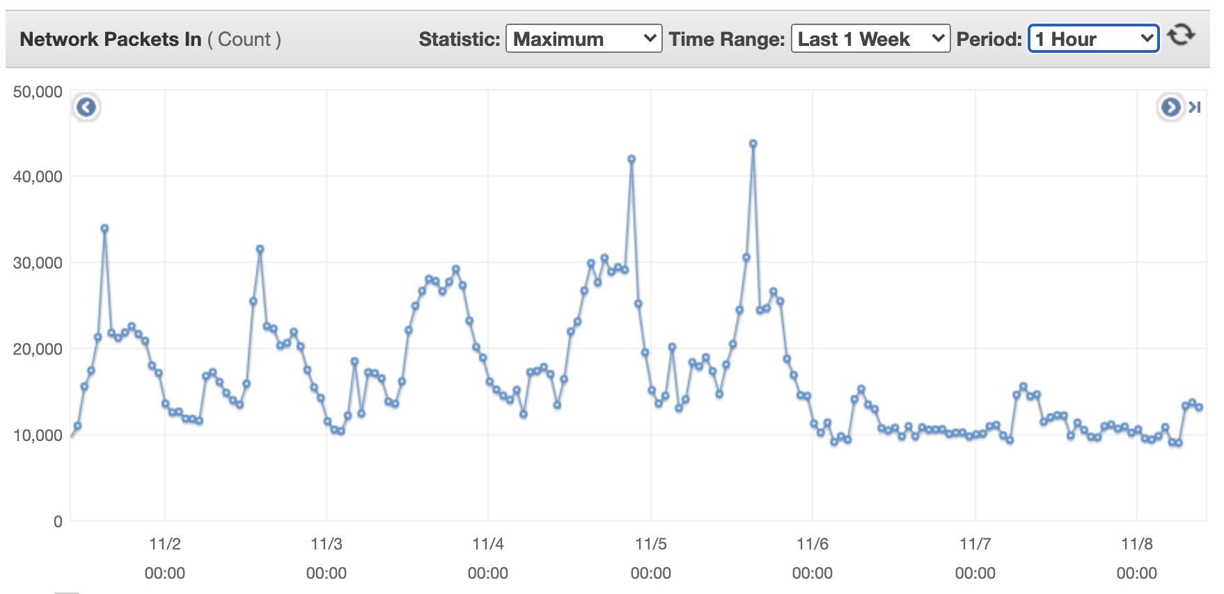
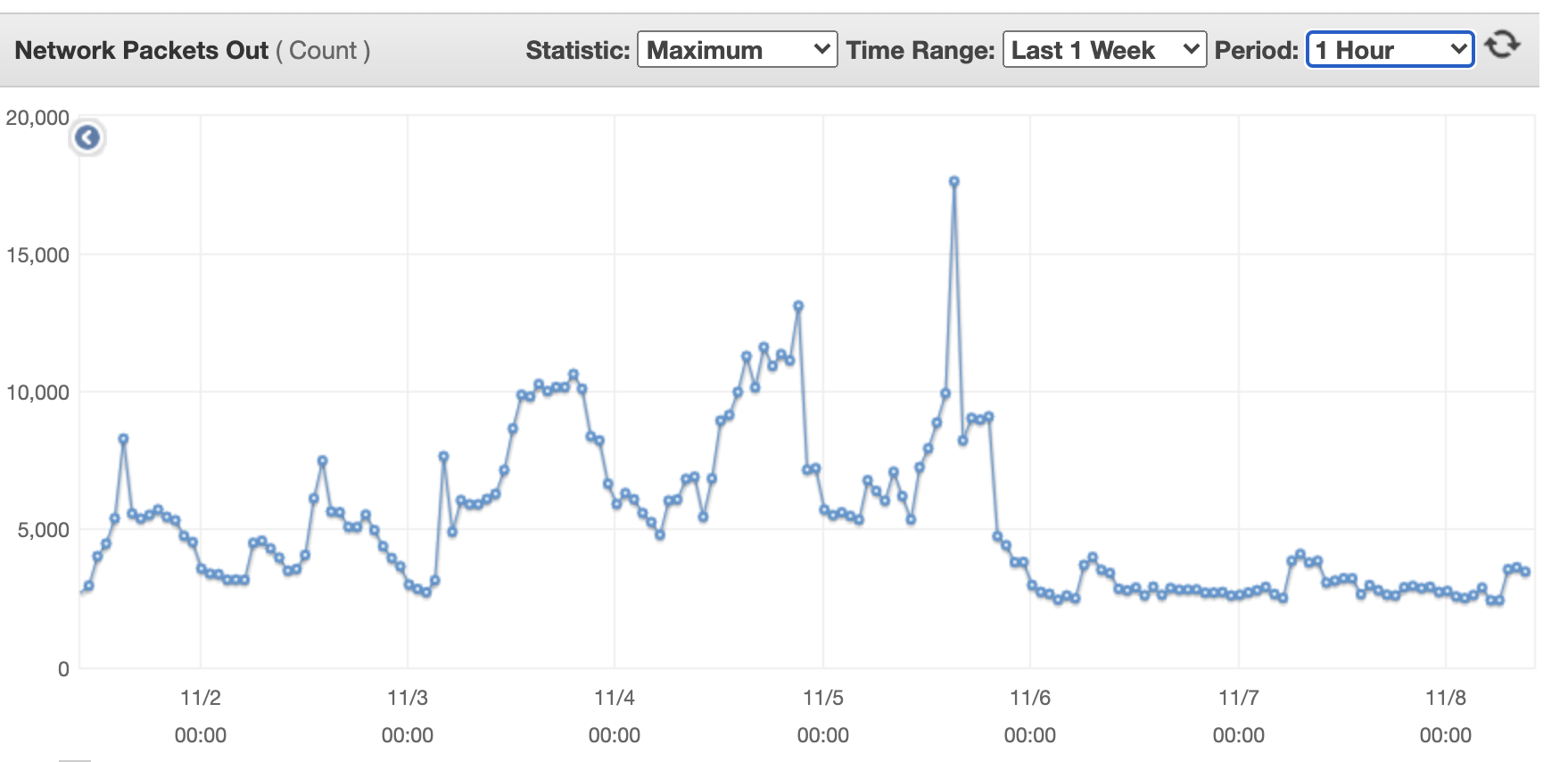
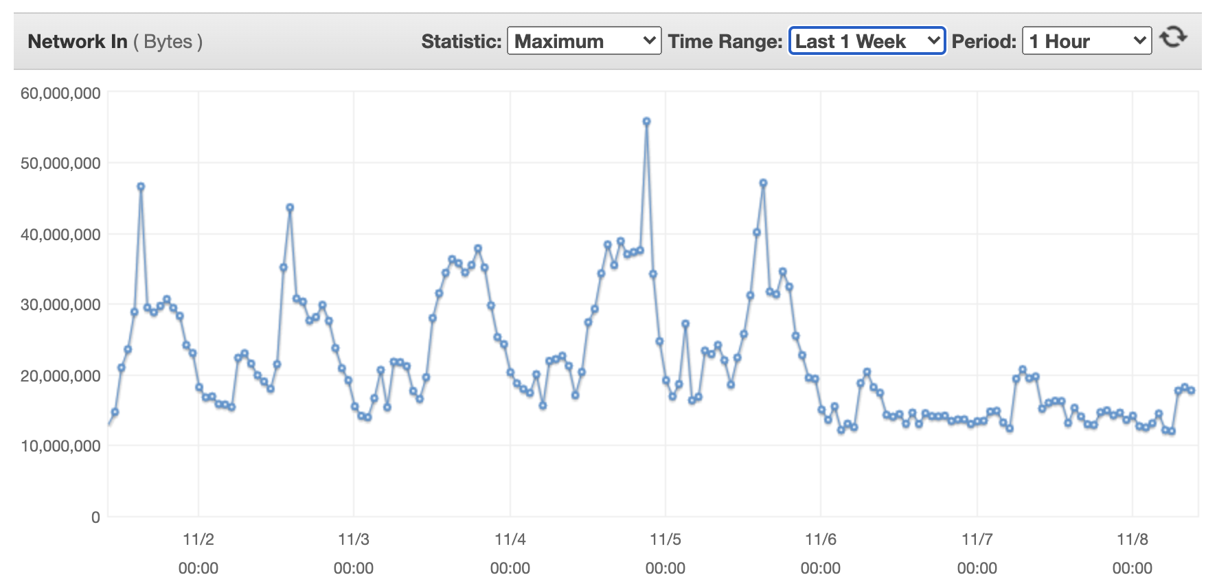
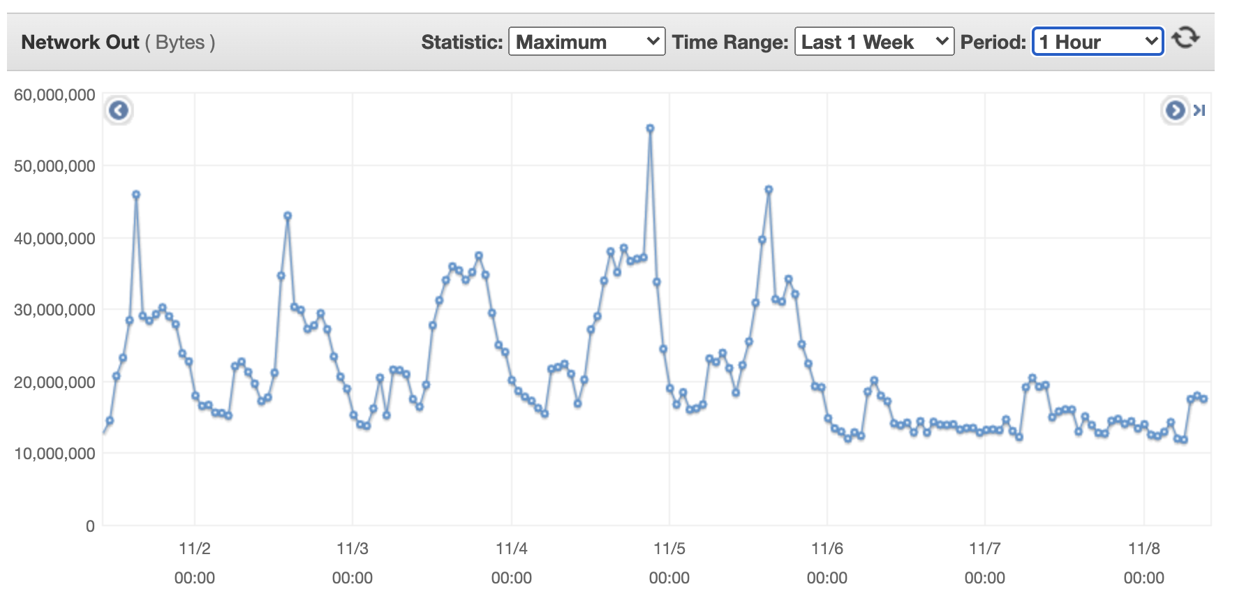
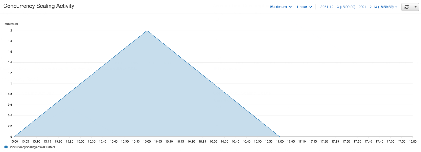
In the following example, we enable concurrency scaling on the Amazon Redshift cluster for the MicroStrategy dashboard queries. We create a user group in Amazon Redshift, and all the dashboard queries are allocated to this user group’s queue. With concurrency scaling in place for the report queries, we can see a significant reduction in query wait time.

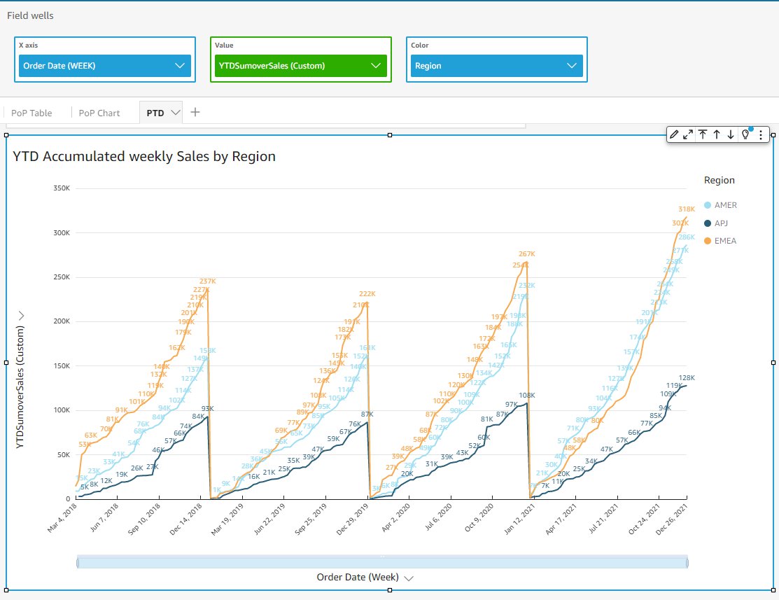
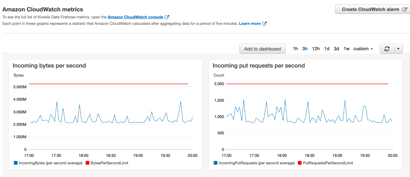
For this example, we created one WLM queue to run our dashboard queries with highest priority and another ETL queue with high priority. Concurrency scaling is turned on for the dashboard queue, as shown in the following screenshot.

As part of this test, we ran several queries in parallel on the cluster, some of which are ETL jobs (insert, delete, update, and copy), and some are complex select queries, such as dashboard queries. The following graph illustrates how many queries are waiting in the WLM queues and how concurrency scaling helps to address those queries.

In the preceding graph, several queries are waiting in the WLM queues; concurrency scaling automatically starts in seconds to process queries without any delays, as shown in the following graph.

This example has demonstrated how concurrency scaling helps handle spikes in user workloads by adding transient clusters as needed to provide consistent performance even as the workload grows to hundreds of concurrent queries.

Amazon Redshift federated queries

Customers using MicroStrategy often connect various relational data sources to a single MicroStrategy project for reporting and analysis purposes. For example, you might integrate an operational (OLTP) data source (such as Amazon Aurora PostgreSQL) and data warehouse data to get meaningful insights into your business.

With federated queries in Amazon Redshift, you can query and analyze data across operational databases, data warehouses, and data lakes. The federated query feature allows you to integrate queries from Amazon Redshift on live data in external databases with queries across your Amazon Redshift and Amazon Simple Storage Service (Amazon S3) environments.

Federated queries help incorporate live data as part of your MicroStrategy reporting and analysis, without the need to connect to multiple relational data sources from MicroStrategy.

You can also use federated queries to MySQL.

This simplifies the multi-source reports use case by having the ability to run queries on both operational and analytical data sources, without the need to explicitly connect and import data from different data sources within MicroStrategy.

Redshift Spectrum

The MicroStrategy Amazon Redshift connector includes support for Redshift Spectrum, so you can connect directly to query data in Amazon Redshift and analyze it in conjunction with data in Amazon S3.

With Redshift Spectrum, you can efficiently query and retrieve structured and semi-structured data (such as PARQUET, JSON, and CSV) from files in Amazon S3 without having to load the data into Amazon Redshift tables. It allows customers with large datasets stored in Amazon S3 to query that data from within the Amazon Redshift cluster using Amazon Redshift SQL queries with no data movement—you pay only for the data you scanned. Redshift Spectrum also allows multiple Amazon Redshift clusters to concurrently query the same dataset in Amazon S3 without the need to make copies of the data for each cluster. Based on the demands of the queries, Redshift Spectrum can intelligently scale out to take advantage of massively parallel processing.

Use cases that might benefit from using Redshift Spectrum include:

  • A large volume of less-frequently accessed data
  • Heavy scan-intensive and aggregation-intensive queries
  • Selective queries that can use partition pruning and predicate pushdown, so the output is fairly small

Redshift Spectrum gives you the freedom to store your data where you want, in the format you want, and have it available for processing when you need it.

With Redshift Spectrum, you take advantage of a fast, cost-effective engine that minimizes data processed with dynamic partition pruning. You can further improve query performance by reducing the amount of data scanned. You could do this by partitioning and compressing data and by using a columnar format for storage.

For more details on how to optimize Redshift Spectrum query performance and cost, see Best Practices for Amazon Redshift Spectrum.

Optimize MicroStrategy

In this section, we discuss ways to optimize MicroStrategy.

SQL optimizations

With MicroStrategy 2021, MicroStrategy has delivered support for 70 new advanced customizable functions to enhance usability and capability, especially when compared to previously existing Apply functions. Application architects can customize the functions and make them ready and available for regular users like business analysts to use! For more information on how to use these new customizable functions, visit the MicroStrategy community site.

SQL Global Optimization

This setting can substantially reduce the number of SQL passes generated by MicroStrategy. In MicroStrategy, SQL Global Optimization reduces the total number of SQL passes with the following optimizations:

  • Eliminates unused SQL passes – For example, a temp table is created but not referenced in a later pass
  • Reuses redundant SQL passes – For example, the exact same temp table is created multiple times when a single temp table is created
  • Combines SQL passes where the SELECT list is different – For example, two temp tables that have the same FROM clause, joins, WHERE clause, and GROUP BY SELECT lists are combined into single SELECT statement
  • Combines SQL passes where the WHERE clause is different – For example, two temp tables that have same the SELECT list, FROM clause, joins, and GROUP BY predicates from the WHERE clause are moved into CASE statements in the SELECT list

The default setting for Amazon Redshift is to enable SQL Global Optimization at its highest level. If your database instance is configured as an earlier version of Amazon Redshift, you may have to enable this setting manually. For more information, see the MicroStrategy System Administration Guide.

Set Operator Optimization

This setting is used to combine multiple subqueries into a single subquery using set operators (such as UNION, INTERSECT, and EXCEPT). The default setting for Amazon Redshift is to enable Set Operator Optimization.

SQL query generation

The MicroStrategy query engine is able to combine multiple passes of SQL that access the same table (typically the main fact table). This can improve performance by eliminating multiple table scans of large tables. For example, this feature significantly reduces the number of SQL passes required to process datasets with custom groups.

Technically, the WHERE clauses of different passes are resolved in CASE statements of a single SELECT clause, which doesn’t contain qualifications in the WHERE clause. Generally, this elimination of WHERE clauses causes a full table scan on a large table.

In some cases (on a report-by-report basis), this approach can be slower than many highly qualified SELECT statements. Because any performance difference between approaches is mostly impacted by the reporting requirement and implementation in the MicroStrategy application, it’s necessary to test both options for each dataset to identify the optimal case.

The default behavior is to merge all passes with different WHERE clauses (level 4). We recommend testing any option for this setting, but most commonly the biggest performance improvements (if any) are observed by switching to the option Level 2: Merge Passes with Different SELECT.

VLDB Category VLDB Property Setting Value
Query Optimizations SQL Global Optimization Level 2: Merge Passes with Different SELECT

SQL size

As we explained earlier, MicroStrategy tries to submit a single query statement containing the analytics of multiple passes in the derived table syntax. This can lead to sizeable SQL query syntax. It’s possible for such a statement to exceed the capabilities of the driver or database. For this reason, MicroStrategy governs the size of generated queries and throws an error message if this is exceeded. Starting with MicroStrategy 10.9, this value is tuned to current Amazon Redshift capabilities (16 MB). Earlier versions specify a smaller limit that can be modified using the following VLDB setting on the Amazon Redshift DB instance in Developer.

VLDB Category VLDB Property Setting Value
Governing SQL Size/MDX Size 16777216

Subquery type

There are many cases in which the SQL engine generates subqueries (query blocks in the WHERE clause):

  • Reports that use relationship filters
  • Reports that use NOT IN set qualification, such as AND NOT
  • Reports that use attribute qualification with M-M relationships; for example, showing revenue by category and filtering on catalog
  • Reports that raise the level of a filter; for example, dimensional metric at Region level, but qualify on store
  • Reports that use non-aggregatable metrics, such as inventory metrics
  • Reports that use dimensional extensions
  • Reports that use attribute-to-attribute comparison in the filter

The default setting for subquery type for Amazon Redshift is Where EXISTS(select (col1, col2…)):

create table T00001 (
       year_id NUMERIC(10, 0),
       W000001 DOUBLE PRECISION)
 DISTSTYLE EVEN
 
insert into ZZMD00DistKey(1)
select a12.year_id  year_id,
       sum(a11.tot_sls_dlr)  W000001
from   items2 a11
       join   dates    a12
         on   (a11.cur_trn_dt = a12.cur_trn_dt)
where ((exists (select      r11.store_nbr
       from   items r11
       where r11.class_nbr = 1
        and   r11.store_nbr = a11.store_nbr))
 and a12.year_id>1993)
group by      a12.year_id

Some reports may perform better with the option of using a temporary table and falling back to IN for a correlated subquery. Reports that include a filter with an AND NOT set qualification (such as AND NOT relationship filter) will likely benefit from using temp tables to resolve the subquery. However, such reports will probably benefit more from using the Set Operator Optimization option discussed earlier. The other settings are not likely to be advantageous with Amazon Redshift.

VLDB Category VLDB Property Setting Value
Query Optimizations Subquery Type Use temporary table, falling back to IN for correlated subquery

Full outer join support

Full outer join support is enabled in the Amazon Redshift object by default. Levels at which you can set this are database instance, report, and template.

For example, the following query shows the use of full outer join with the states_dates and regions tables:

select pa0.region_id W000000,
       pa2.month_id W000001,
       sum(pa1.tot_dollar_sales) Column1
from   states_dates pa1
       full outer join       regions     pa0
         on (pa1.region_id = pa0.region_id)
       cross join    LU_MONTH      pa2
group by      pa0.region_id, pa2.month_id

DISTINCT or GROUP BY option (for no aggregation and no table key)

If no aggregation is needed and the attribute defined on the table isn’t a primary key, this property tells the SQL engine whether to use SELECT DISTINCT, GROUP BY, or neither.

Possible values for this setting include:

  • Use DISTINCT
  • No DISTINCT, no GROUP BY
  • Use GROUP BY

The DISTINCT or GROUP BY option property controls the generation of DISTINCT or GROUP BY in the SELECT SQL statement. The SQL engine doesn’t consider this property if it can make the decision based on its own knowledge. Specifically, the SQL engine ignores this property in the following situations:

  • If there is aggregation, the SQL engine uses GROUP BY, not DISTINCT
  • If there is no attribute (only metrics), the SQL engine doesn’t use DISTINCT
  • If there is COUNT (DISTINCT …) and the database doesn’t support it, the SQL engine performs a SELECT DISTINCT pass and then a COUNT(*) pass
  • If for certain selected column data types, the database doesn’t allow DISTINCT or GROUP BY, the SQL engine doesn’t do it
  • If the SELECT level is the same as the table key level and the table’s true key property is selected, the SQL engine doesn’t issue a DISTINCT

When none of the preceding conditions are met, the SQL engine uses the DISTINCT or GROUP BY property.

Use the latest Amazon Redshift drivers

For running MicroStrategy reports using Amazon Redshift, we encourage upgrading when new versions of the Amazon Redshift drivers are available. Running an application on the latest driver provides better performance, bugs recovery, and better security features. To get the latest driver version based on the OS, see Drivers and Connectors.

Conclusion

In this post, we discussed various Amazon Redshift cluster optimizations, data model optimizations, and SQL optimizations within MicroStrategy for optimizing your Amazon Redshift and MicroStrategy deployment.


About the Authors

Ranjan Burman is an Analytics Specialist Solutions Architect at AWS. He specializes in Amazon Redshift and helps customers build scalable analytical solutions. He has more than 13 years of experience in different database and data warehousing technologies. He is passionate about automating and solving customer problems with the use of cloud solutions.

Nita Shah is a Analytics Specialist Solutions Architect at AWS based out of New York. She has been building data warehouse solutions for over 20 years and specializes in Amazon Redshift. She is focused on helping customers design and build enterprise-scale well-architected analytics and decision support platforms.

Bosco Albuquerque is a Sr Partner Solutions Architect at AWS and has over 20 years of experience working with database and analytics products from enterprise database vendors and cloud providers, and has helped large technology companies design data analytics solutions as well as led engineering teams in designing and implementing data analytics platforms and data products.

Amit Nayak is responsible for driving the Gateways roadmap at MicroStrategy, focusing on relational and big data databases, as well as authentication. Amit joined MicroStrategy after completing his master’s in Business Analytics at George Washington University and has maintained an oversight of the company’s gateways portfolio for the 3+ years he has been with the company.

Add comparative and cumulative date/time calculations in Amazon QuickSight

Post Syndicated from Emily Zhu original https://aws.amazon.com/blogs/big-data/add-comparative-and-cumulative-date-time-calculations-in-amazon-quicksight/

Amazon QuickSight recently added native support for comparative (e.g., year-over-year) and cumulative (e.g., year-to-date) period functions which allow you to easily introduce these calculations in business reporting, trend analysis and time series analysis. This allows authors in QuickSight to implement advanced calculations without having to use complicated date offsets in calculations to achieve such datetime-aware comparisons.

In this post, we introduce the new period functions and their capabilities, and demonstrate several typical use cases. We also discuss several scenarios to extend the usage of the period functions, which will be useful in more advanced situations.

New period functions

Before we demonstrate use cases, let’s go over the new period function suite and see what new functions we now support. We can divide period functions into two main groups: comparative (period over period) functions and cumulative (period to date) functions.

Comparative (period over period) functions

You can use period over period functions to compare measures at different time periods, such as year, quarter, and month. For example, you can compute a year-over-year increase in sales, or week-over-week percentage revenue changes.

A typical comparative period function has the syntax periodOverPeriodDifference(measure, date, period, offset), with two optional arguments: period and offset.

You can use the period argument in the function to define the period granularity of the calculation. The granularity of YEAR means year-over-year computation, Quarter means quarter-over-quarter, and so on. If the period argument is left empty, the calculation changes based on the period granularity that is chosen (in the field well) to be displayed in the visual.

You can also use the offset argument to specify how many periods apart you want to compute the comparison. For instance, a period of a quarter with an offset of 2 means comparing against the previous two quarters.

Note that period and offset have to be both specified or both left empty. You can’t specify just one of them.

The following table summarizes the three available period over period functions.

Function Name Function Type Description
periodOverPeriodDifference Table Calculation Calculates the difference of a measure over two different time periods as specified by period granularity and offset.
periodOverPeriodLastValue Table Calculation Calculates the last (previous) value of a measure from a previous time period as specified by period granularity and offset.
periodOverPeriodPercentDifference Table Calculation Calculates the percent difference of a measure over two different time periods as specified by period granularity and offset.

Cumulative (period to date) functions

You can use period to date functions to calculate metrics within a given period-to-date window. There are two main types of cumulative functions.

  • “OverTime” functions, which are table calculations and return outputs for each row in the visual.

E.g., you can use periodToDateCountOverTime with WEEK granularity to compute a series of week-to-date new customer counts to track the fluctuation of customer engagement.

  • Aggregation functions, which output an aggregated value for a fixed period-to-date time range.

E.g., periodtoDateSum with YEAR granularity returns a single value for the total of the metric from the beginning of the year to the endDate provided in the formula. If left blank, the default endDate takes now(), which is the moment when users load the dashboard.

The following table summarizes the period to date functions.

Function Name Function Type Description
periodToDateAvgOverTime Table Calculation Calculates the average of a measure for a given time granularity (for instance, a quarter) up to a point in time.
periodToDateCountOverTime Table Calculation Calculates the count of a dimension or measure for a given time granularity (for instance, a quarter) up to a point in time.
periodToDateMaxOverTime Table Calculation Calculates the maximum of a measure or date for a given time granularity (for instance, a quarter) up to a point in time.
periodToDateMinOverTime Table Calculation Calculates the minimum of a measure or date for a given time granularity (for instance, a quarter) up to a point in time.
periodToDateSumOverTime Table Calculation Calculates the sum of a measure for a given time granularity (for instance, a quarter) up to a point in time.
periodToDateAvg Aggregation Averages the set of numbers in the specified measure for a given time granularity (for instance, a quarter) up to a point in time.
periodToDateCount Aggregation Calculates the number of values in a dimension or measure for a given time granularity (for instance, a quarter) up to a point in time, including duplicates.
periodToDateMax Aggregation Returns the maximum value of the specified measure for a given time granularity (for instance, a quarter) up to a point in time.
periodToDateMedian Aggregation Returns the median value of the specified measure for a given time granularity (for instance, a quarter) up to a point in time.
periodToDateMin Aggregation Returns the minimum value of the specified measure or date for a given time granularity (for instance, a quarter) up to a point in time.
periodToDatePercentile Aggregation Calculates the percentile based on the actual numbers in the measure for a given time granularity (for instance, a quarter) up to a point in time.
periodToDatePercentileCont Aggregation Calculates the percentile based on a continuous distribution of the numbers in the measure for a given time granularity (for instance, a quarter) up to a point in time.
periodToDateStDev Aggregation Calculates the standard deviation of the set of numbers in the specified measure for a given time granularity (for instance, a quarter) up to a point in time based on a sample.
periodToDateStDevP Aggregation Calculates the population standard deviation of the set of numbers in the specified measure for a given time granularity (for instance, a quarter) up to a point in time based on a sample.
periodtoDateSum Aggregation Adds the set of numbers in the specified measure for a given time granularity (for instance, a quarter) up to a point in time.
periodToDateVar Aggregation Calculates the sample variance of the set of numbers in the specified measure for a given time granularity (for instance, a quarter) up to a point in time.
periodToDateVarP Aggregation Calculates the population variance of the set of numbers in the specified measure for a given time granularity (for instance, a quarter) up to a point in time.

Use case 1: Using a period over period function to analyze sales growth in fixed and dynamic granularity

Let’s dive into how period over period functions can support typical business and financial use cases. The following example uses periodOverPeriodDifference to calculate YoY sales growth. Because we have Segment and Region in the visual, the YoY sales is calculated for each segment and region.

We define the measure of YoYSales with the following formula: YoYSales=periodOverPeriodDifference(sum(Sales),{Order Date},YEAR,1)

The first argument, sum(Sales), tells the function to calculate based on this measure. The second argument, Order Date, specifies the date/time column from which Year information is extracted. The third argument, YEAR, fixes the granularity of this calculation. When this optional argument is specified, this measure always returns YoY (not QoQ or MoM) no matter how Order Date is selected (in the field well) to be displayed in the visual. The fourth argument, 1, specifies the offset of the comparison. In this example, it means we want to compare the sales of each order date with the same date of the previous year. The measure returns empty for order dates of 2018, because no previous periods exist to be compared with.

The period functions are working with totals and subtotals. By adding the total for columns into the visual, you can see the total sales and total YoYSales for each region.

If you leave the optional argument of period granularity empty, meaning change the formula to PoPSales=periodOverPeriodDifference(sum(Sales),{Order Date})as shown in the following example, the time period of the calculation is then determined by the granularity of Order Date displayed on the visual. In the following example, Order Date is chosen to display at quarter level (in the field well), so PoPSales dynamically calculates the QoQ sales growth. Changing Order Date to the monthly level updates the measure to calculate MoM. For PoPSales, only Q1 2018 returns empty because that’s the only quarter that doesn’t have a previous quarter to compare with.

If we add YoYSales from the previous example to this visual, it calculates YoY sales growth at the quarter level (compares sales of Q1 2019 with Q1 2018). This demonstrates the difference between a fixed granularity and a dynamic granularity of period over period functions.

The period over period functions can differentiate between a positive change (increase) and negative change (decrease). Therefore, when we add the conditional formatting to the visual, it’s very straightforward to see the financial performance of each period (green is good, red is bad).

Similarly, you can use periodOverPeriodPercentDifference to calculate relative sales growth over time. You can add dimensions into the visual to dive further into business insights, such as analyzing the breakdown of each business segment’s sales change by quarter, and their contribution to the total sales increase. We use the formula PoPSales%=periodOverPeriodPercentDifference(sum(Sales),{Order Date}).

Use case 2: Using a period to date function to track YTD sales in table calculations and aggregations

Similar to period over period functions, the period to date function suite provides a quick and easy way to calculate year-to-date (YTD) or quarter-to-date (QTD) metrics. In the following example, we use the formula of YTDSumoverSales=periodToDateSumOverTime(sum(Sales),{Order Date},YEAR), and YTDtotalcountSales=periodToDateSumOverTime(count(Sales),{Order Date},YEAR) to calculate YTD sales and YTD total number of transactions.

Contrary to period over period functions, the third argument of period to date functions, period, isn’t optional. Therefore, the calculation granularity is always fixed. In this example, with the granularity defined as YEAR, this measure always calculates YTD, instead of QTD or MTD. Because Order Date is displayed at the monthly level, this calculation outputs the YTD sales of each month, and starts over again in January for the next year. As shown in the result table, YTDSumoverSales of January 2018 is the monthly sales of January 2018, and YTDSumoverSales of February 2018 is the monthly sales of January 2018 plus that of February 2018. And YTDSumoverSales of January 2019 goes back to the monthly sales of January 2019.

You can further dive into the details by populating the calculations in a line chart, and adding more dimensions into the analysis. The following example shows the YTD weekly sales growth trend for each region along the past four years, and uncovers some interesting sales competition between AMER and EMEA in year 2021.

In addition to the table calculations, the aggregation period functions are particularly useful when you need to build KPI charts to evaluate YTD metrics in a real-time manner. In the following example, we use the aggregation period to date functions to build two KPI charts to track the YTD total sales, and YTD total number of transactions. For the date December 26, 2021, the timestamp results match the corresponding table calculations for the date of December 26, 2021 in the table. The following table summarizes the formulas.

Formula Formula Type
YTDSumoverSales=periodToDateSumOverTime(sum(Sales),{Order Date},YEAR) Table Calculation
YTDtotalcountSales=periodToDateSumOverTime(count(Sales),{Order Date},YEAR) Table Calculation
YTDSumSales=periodToDateSum(Sales,{Order Date},YEAR) Aggregation (KPI chart)
YTDCountSales=periodToDateCount(Sales,{Order Date},YEAR) Aggregation (KPI chart)

Advanced use case 1: Date/time awareness with period functions

Period functions are not only easier to define and read, they’re also date/time-aware, meaning the functions are calculated based on a date/time-based offset instead of a fixed number of rows. It can solve two major problems that were not possible to be addressed before.

Period functions can handle varying period duration

If you want to calculate the daily MoM sales increase, you can’t use a fixed offset on each month because the number of days of each month are different (31 days for January and 28 or 29 days for February).

Period functions are calculated based on calendar dates instead of a fixed offset. In the following example, we use the formula MoMsalesDiff=periodOverPeriodDifference(sum(Sales),{Order Date},MONTH,1). The daily MoM increase is calculated correctly based on the day of the month. The sales of the first day of the month are compared with the first day of the previous month, and the same applies to all other days. (Visuals are duplicated for demonstration purposes.)

Period functions can handle sparse (missing) data points

Not all datasets can guarantee a complete set of dates. In the previous example, sales data of January 1, 2018, is missing. Using the workaround based on a fixed offset can cause a problem here because we compare February 1, 2018, with a different date instead of January 1, 2018. Period functions always compare measures by date/time offsets so that only desired dates are compared. In the previous example, MoMsalesDiff shows empty for February 1, 2018, because of the missing data of January 1, 2018.

Advanced use case 2: Nesting period functions with other calculations

Now that we can use period over period and period to date functions to create calculated fields, we can nest these functions with other calculations to drive more advanced analysis.

For example, you may want to know for each year, what are the top 10 weeks of the year in regards to week-over-week sales growth. You can do this by calculating WoWSales first: WoWSales=periodOverPeriodDifference(sum(Sales), {Order Date}, WEEK, 1). Then you nest it with the denseRank window function: RankWoWSales=denseRank([WoWSales DESC],[{YEAR}]). This wouldn’t be possible using the fixed-row based workaround, which is implemented using on-visual calculations instead of calculated fields. In the following visual, the top 10 weeks of each year with the highest sales growth are fetched by a simple filter on RankWoWSales.

You can even nest the period functions with other period functions to generate interesting insights. For example, you can calculate a monthly YoY growth based on the monthly YTD number of transactions. The following formula demonstrates the capability of nesting a YTD calculated field inside a YoY calculated field:

YTDtotalsountSales=periodToDateSumOverTime(count(Sales),{Order Date},YEAR)
YoYYTDSalesCount=periodOverPeriodDifference(YTDtotalcountSales,{Order Date},YEAR,1)

The results in the following visual show a YoY growth based on a YTD accumulated number of transactions instead of the absolute monthly numbers.

Advanced use case 3: Partial period comparisons

Finally, we discuss a third advanced use case: partial period comparison. Imagine it’s November 15, 2021 (which is the 46th day of the last quarter of 2021), and you want to calculate 4 to compare the performance of this quarter with past quarters, but only using the first 46 days of each quarter instead of the whole quarter. This requires a calculated field using periodOverPeriodDifference nested with the sumIf() window function.

The following example demonstrates using a nested calculated field to address this use case:

QuarterToDate=periodToDateSumOverTime(sum(Sales), {Order Date}, QUARTER)
PartialQTDSales=sumIf(Sales, dateDiff(truncDate("Q", {Order Date}), {Order Date}, "HH") <= dateDiff(truncDate("Q", now()), now(), "HH"))
PartialQoQQTDSales=periodOverPeriodDifference(sumif(Sales, {Order Date} <= addDateTime(dateDiff(truncDate("Q", now()), now(), "HH"), "HH", truncDate("Q", {Order Date}))), {Order Date}, QUARTER, 1)

PartialQTDSales computes how many hours from the beginning of this quarter to the current date and uses sumIf() to calculate the total sales of that period of each quarter. partialQoQQTDSales then nests the periodOverPeriodDifference function with PartialQTDSales to find the partial QoQ differences. Such a comparison based on a partial period isn’t feasible without the new date/time-aware period functions.

Conclusion

In this blog, we introduced new QuickSight period functions which enable quick and powerful date/time-based calculations. We reviewed comparative and cumulative period functions (i.e., period over period and period to date), discussed two major use cases (fixed vs. dynamic granularity and table calculation vs. aggregation), and extended the usage to three advanced use cases. Period functions are now generally available in all supported QuickSight Regions.

Looking forward to your feedback and stories on how you apply these calculations for your business needs.


About the Authors

Emily Zhu is a Senior Product Manager at Amazon QuickSight, AWS’s cloud-native, fully managed SaaS BI service. She leads the development of QuickSight core analytics and calculations capability. Before joining AWS, she was working in the Amazon Prime Air drone delivery program and the Boeing company as senior strategist for several years. Emily is passionate about potentials of cloud-based BI solutions and looks forward to helping customers to advance in their data-driven strategy making.

Rajkumar Haridoss is a Senior Software Development Engineer for AWS QuickSight. He is the lead engineer on the Query Generation team and works on back-end calculations, query planning, and query generation layer in QuickSight. Outside of work, he likes spending quality time with family and 4-year-old.

Validate streaming data over Amazon MSK using schemas in cross-account AWS Glue Schema Registry

Post Syndicated from Vikas Bajaj original https://aws.amazon.com/blogs/big-data/validate-streaming-data-over-amazon-msk-using-schemas-in-cross-account-aws-glue-schema-registry/

Today’s businesses face an unprecedented growth in the volume of data. A growing portion of the data is generated in real time by IoT devices, websites, business applications, and various other sources. Businesses need to process and analyze this data as soon as it arrives to make business decisions in real time. Amazon Managed Streaming for Apache Kafka (Amazon MSK) is a fully managed service that enables building and running stream processing applications that use Apache Kafka to collect and process data in real time.

Stream processing applications using Apache Kafka don’t communicate with each other directly; they communicate via sending and receiving messages over Kafka topics. For stream processing applications to communicate efficiently and confidently, a message payload structure must be defined in terms of attributes and data types. This structure describes the schema applications use when sending and receiving messages. However, with a large number of producer and consumer applications, even a small change in schema (removing a field, adding a new field, or change in data type) may cause issues for downstream applications that are difficult to debug and fix.

Traditionally, teams have relied on change management processes (such as approvals and maintenance windows) or other informal mechanisms (documentation, emails, collaboration tools, and so on) to inform one another of data schema changes. However, these mechanisms don’t scale and are prone to mistakes. The AWS Glue Schema Registry allows you to centrally publish, discover, control, validate, and evolve schemas for stream processing applications. With the AWS Glue Schema Registry, you can manage and enforce schemas on data streaming applications using Apache Kafka, Amazon MSK, Amazon Kinesis Data Streams, Amazon Kinesis Data Analytics for Apache Flink, and AWS Lambda.

This post demonstrates how Apache Kafka stream processing applications validate messages using an Apache Avro schema stored in the AWS Glue Schema registry residing in a central AWS account. We use the AWS Glue Schema Registry SerDe library and Avro SpecificRecord to validate messages in stream processing applications while sending and receiving messages from a Kafka topic on an Amazon MSK cluster. Although we use an Avro schema for this post, the same approach and concept applies to JSON schemas as well.

Use case

Let’s assume a fictitious rideshare company that offers unicorn rides. To draw actionable insights, they need to process a stream of unicorn ride request messages. They expect rides to be very popular and want to make sure their solution can scale. They’re also building a central data lake where all their streaming and operation data is stored for analysis. They’re customer obsessed, so they expect to add new fun features to future rides, like choosing the hair color of your unicorn, and will need to reflect these attributes in the ride request messages. To avoid issues in downstream applications due to future schema changes, they need a mechanism to validate messages with a schema hosted in a central schema registry. Having schemas in a central schema registry makes it easier for the application teams to publish, validate, evolve, and maintain schemas in a single place.

Solution overview

The company uses Amazon MSK to capture and distribute the unicorn ride request messages at scale. They define an Avro schema for unicorn ride requests because it provides rich data structures, supports direct mapping to JSON, as well as a compact, fast, and binary data format. Because the schema was agreed in advance, they decided to use Avro SpecificRecord.SpecificRecord is an interface from the Avro library that allows the use of an Avro record as a POJO. This is done by generating a Java class (or classes) from the schema, by using avro-maven-plugin. They use AWS Identity and Access Management (IAM) cross-account roles to allow producer and consumer applications from the other AWS account to safely and securely access schemas in the central Schema Registry account.

The AWS Glue Schema Registry is in Account B, whereas the MSK cluster and Kafka producer and consumer applications are in Account A. We use the following two IAM roles to enable cross-account access to the AWS Glue Schema Registry. Apache Kafka clients in Account A assume a role in Account B using an identity-based policy because the AWS Glue Schema Registry doesn’t support resource-based policies.

  • Account A IAM role – Allows producer and consumer applications to assume an IAM role in Account B.
  • Account B IAM role – Trusts all IAM principals from Account A and allows them to perform read actions on the AWS Glue Schema Registry in Account B. In a real use case scenario, IAM principals that can assume cross-account roles should be scoped more specifically.

The following architecture diagram illustrates the solution:

The solution works as follows:

  1. A Kafka producer running in Account A assumes the cross-account Schema Registry IAM role in Account B by calling the AWS Security Token Service (AWS STS) assumeRole API.
  2. The Kafka producer retrieves the unicorn ride request Avro schema version ID from the AWS Glue Schema Registry for the schema that’s embedded in the unicorn ride request POJO. Fetching the schema version ID is internally managed by the AWS Glue Schema Registry SerDe’s serializer. The serializer has to be configured as part of the Kafka producer configuration.
  3. If the schema exists in the AWS Glue Schema Registry, the serializer decorates the data record with the schema version ID and then serializes it before delivering it to the Kafka topic on the MSK cluster.
  4. The Kafka consumer running in Account A assumes the cross-account Schema Registry IAM role in Account B by calling the AWS STS assumeRole API.
  5. The Kafka consumer starts polling the Kafka topic on the MSK cluster for data records.
  6. The Kafka consumer retrieves the unicorn ride request Avro schema from the AWS Glue Schema Registry, matching the schema version ID that’s encoded in the unicorn ride request data record. Fetching the schema is internally managed by the AWS Glue Schema Registry SerDe’s deserializer. The deserializer has to be configured as part of the Kafka consumer configuration. If the schema exists in the AWS Glue Schema Registry, the deserializer deserializes the data record into the unicorn ride request POJO for the consumer to process it.

The AWS Glue Schema Registry SerDe library also supports optional compression configuration to save on data transfers. For more information about the Schema Registry, see How the Schema Registry works.

Unicorn ride request Avro schema

The following schema (UnicornRideRequest.avsc) defines a record representing a unicorn ride request, which contains ride request attributes along with the customer attributes and system-recommended unicorn attributes:

{
    "type": "record",
    "name": "UnicornRideRequest",
    "namespace": "demo.glue.schema.registry.avro",
    "fields": [
      {"name": "request_id", "type": "int", "doc": "customer request id"},
      {"name": "pickup_address","type": "string","doc": "customer pickup address"},
      {"name": "destination_address","type": "string","doc": "customer destination address"},
      {"name": "ride_fare","type": "float","doc": "ride fare amount (USD)"},
      {"name": "ride_duration","type": "int","doc": "ride duration in minutes"},
      {"name": "preferred_unicorn_color","type": {"type": "enum","name": "UnicornPreferredColor","symbols": ["WHITE","BLACK","RED","BLUE","GREY"]}, "default": "WHITE"},
      {
        "name": "recommended_unicorn",
        "type": {
          "type": "record",
          "name": "RecommendedUnicorn",
          "fields": [
            {"name": "unicorn_id","type": "int", "doc": "recommended unicorn id"},
            {"name": "color","type": {"type": "enum","name": "unicorn_color","symbols": ["WHITE","RED","BLUE"]}},
            {"name": "stars_rating", "type": ["null", "int"], "default": null, "doc": "unicorn star ratings based on customers feedback"}
          ]
        }
      },
      {
        "name": "customer",
        "type": {
          "type": "record",
          "name": "Customer",
          "fields": [
            {"name": "customer_account_no","type": "int", "doc": "customer account number"},
            {"name": "first_name","type": "string"},
            {"name": "middle_name","type": ["null","string"], "default": null},
            {"name": "last_name","type": "string"},
            {"name": "email_addresses","type": ["null", {"type":"array", "items":"string"}]},
            {"name": "customer_address","type": "string","doc": "customer address"},
            {"name": "mode_of_payment","type": {"type": "enum","name": "ModeOfPayment","symbols": ["CARD","CASH"]}, "default": "CARD"},
            {"name": "customer_rating", "type": ["null", "int"], "default": null}
          ]
        }
      }
    ]
  }

Prerequisites

To use this solution, you must have two AWS accounts:

  • Account A – For the MSK cluster, Kafka producer and consumer Amazon Elastic Compute Cloud (Amazon EC2) instances, and AWS Cloud9 environment
  • Account B – For the Schema Registry and schema

For this solution, we use Region us-east-1, but you can change this as per your requirements.

Next, we create the resources in each account using AWS CloudFormation templates.

Create resources in Account B

We create the following resources in Account B:

  • A schema registry
  • An Avro schema
  • An IAM role with the AWSGlueSchemaRegistryReadonlyAccess managed policy and an instance profile, which allows all Account A IAM principals to assume it
  • The UnicornRideRequest.avsc Avro schema shown earlier, which is used as a schema definition in the CloudFormation template

Make sure you have the appropriate permissions to create these resources.

  1. Log in to Account B.
  2. Launch the following CloudFormation stack.
  3. For Stack name, enter SchemaRegistryStack.
  4. For Schema Registry name, enter unicorn-ride-request-registry.
  5. For Avro Schema name, enter unicorn-ride-request-schema-avro.
  6. For the Kafka client’s AWS account ID, enter your Account A ID.
  7. For ExternalId, enter a unique random ID (for example, demo10A), which should be provided by the Kafka clients in Account A while assuming the IAM role in this account.

For more information about cross-account security, see The confused deputy problem.

  1. When the stack is complete, on the Outputs tab of the stack, copy the value for CrossAccountGlueSchemaRegistryRoleArn.

The Kafka producer and consumer applications created in Account A assume this role to access the Schema Registry and schema in Account B.

  1. To verify the resources were created, on the AWS Glue console, choose Schema registries in the navigation bar, and locate unicorn-ride-request-registry.
  2. Choose the registry unicorn-ride-request-registry and verify that it contains unicorn-ride-request-schema-avro in the Schemas section.
  3. Choose the schema to see its content.

The IAM role created by the SchemaRegistryStack stack allows all Account A IAM principals to assume it and perform read actions on the AWS Glue Schema Registry. Let’s look at the trust relationships of the IAM role.

  1. On the SchemaRegistryStack stack Outputs tab, copy the value for CrossAccountGlueSchemaRegistryRoleName.
  2. On the IAM console, search for this role.
  3. Choose Trust relationships and look at its trusted entities to confirm that Account A is listed.
  4. In the Conditions section, confirm that sts:ExternalId has the same unique random ID provided during stack creation.

Create resources in Account A

We create the following resources in Account A:

  • A VPC
  • EC2 instances for the Kafka producer and consumer
  • An AWS Cloud9 environment
  • An MSK cluster

As a prerequisite, create an EC2 keypair and download it on your machine to be able to SSH into EC2 instances. Also create an MSK cluster configuration with default values. You need to have permissions to create the CloudFormation stack, EC2 instances, AWS Cloud9 environment, MSK cluster, MSK cluster configuration, and IAM role.

  1. Log in to Account A.
  2. Launch the following CloudFormation stack to launch the VPC, EC2 instances, and AWS Cloud9 environment.
  3. For Stack name, enter MSKClientStack.
  4. Provide the VPC and subnet CIDR ranges.
  5. For EC2 Keypair, choose an existing EC2 keypair.
  6. For the latest EC2 AMI ID, select the default option.
  7. For the cross-account IAM role ARN, use the value for CrossAccountGlueSchemaRegistryRoleArn (available on the Outputs tab of SchemaRegistryStack).
  8. Wait for the stack to create successfully.
  9. Launch the following CloudFormation stack to create the MSK cluster.
  10. For Stack name, enter MSKClusterStack.
  11. Use Amazon MSK version 2.7.1.
  12. For the MSK cluster configuration ARN, enter the MSK cluster configuration ARN. One that you created as part of the prerequisite.
  13. For the MSK cluster configuration revision number, enter 1 or change it according to your version.
  14. For the client CloudFormation stack name, enter MSKClientStack (the stack name that you created prior to this stack).

Configure the Kafka producer

To configure the Kafka producer accessing the Schema Registry in the central AWS account, complete the following steps:

  1. Log in to Account A.
  2. On the AWS Cloud9 console, choose the Cloud9EC2Bastion environment created by the MSKClientStack stack.
  3. On the File menu, choose Upload Local Files.
  4. Upload the EC2 keypair file that you used earlier while creating the stack.
  5. Open a new terminal and change the EC2 keypair permissions:
    chmod 0400 <keypair PEM file>

  6. SSH into the KafkaProducerInstance EC2 instance and set the Region as per your requirement:
    ssh -i <keypair PEM file> ec2-user@<KafkaProducerInstance Private IP address>
    aws configure set region <region>

  7. Set the environment variable MSK_CLUSTER_ARN pointing to the MSK cluster’s ARN:
    export MSK_CLUSTER_ARN=$(aws kafka list-clusters |  jq '.ClusterInfoList[] | select (.ClusterName == "MSKClusterStack") | {ClusterArn} | join (" ")' | tr -d \")

Change the .ClusterName value in the code if you used a different name for the MSK cluster CloudFormation stack. The cluster name is the same as the stack name.

  1. Set the environment variable BOOTSTRAP_BROKERS pointing to the bootstrap brokers:
    export BOOTSTRAP_BROKERS=$(aws kafka get-bootstrap-brokers --cluster-arn $MSK_CLUSTER_ARN | jq -r .BootstrapBrokerString)

  2. Verify the environment variables:
    echo $MSK_CLUSTER_ARN
    echo $BOOTSTRAP_BROKERS

  3. Create a Kafka topic called unicorn-ride-request-topic in your MSK cluster, which is used by the Kafka producer and consumer applications later:
    cd ~/kafka
    
    ./bin/kafka-topics.sh --bootstrap-server $BOOTSTRAP_BROKERS \
    --topic unicorn-ride-request-topic \
    --create --partitions 3 --replication-factor 2
    
    ./bin/kafka-topics.sh --bootstrap-server $BOOTSTRAP_BROKERS --list

The MSKClientStack stack copied the Kafka producer client JAR file called kafka-cross-account-gsr-producer.jar to the KafkaProducerInstance instance. It contains the Kafka producer client that sends messages to the Kafka topic unicorn-ride-request-topic on the MSK cluster and accesses the unicorn-ride-request-schema-avro Avro schema from the unicorn-ride-request-registry schema registry in Account B. The Kafka producer code, which we cover later in this post, is available on GitHub.

  1. Run the following commands and verify kafka-cross-account-gsr-producer.jar exists:
    cd ~
    ls -ls

  2. Run the following command to run the Kafka producer in the KafkaProducerInstance terminal:
    java -jar kafka-cross-account-gsr-producer.jar -bs $BOOTSTRAP_BROKERS \
    -rn <Account B IAM role arn that Kafka producer application needs to assume> \
    -topic unicorn-ride-request-topic \
    -reg us-east-1 \
    -nm 500 \
    -externalid <Account B IAM role external Id that you used while creating a CF stack in Account B>

The code has the following parameters:

  • -bs$BOOTSTRAP_BROKERS (the MSK cluster bootstrap brokers)
  • -rn – The CrossAccountGlueSchemaRegistryRoleArn value from the SchemaRegistryStack stack outputs in Account B
  • -topic – the Kafka topic unicorn-ride-request-topic
  • -regus-east-1 (change it according to your Region, it’s used for the AWS STS endpoint and Schema Registry)
  • -nm: 500 (the number of messages the producer application sends to the Kafka topic)
  • -externalId – The same external ID (for example, demo10A) that you used while creating the CloudFormation stack in Account B

The following screenshot shows the Kafka producer logs showing Schema Version Id received..., which means it has retrieved the Avro schema unicorn-ride-request-schema-avro from Account B and messages were sent to the Kafka topic on the MSK cluster in Account A.

Kafka producer code

The complete Kafka producer implementation is available on GitHub. In this section, we break down the code.

  • getProducerConfig() initializes the producer properties, as shown in the following code:
    • VALUE_SERIALIZER_CLASS_CONFIG – The GlueSchemaRegistryKafkaSerializer.class.getName() AWS serializer implementation that serializes data records (the implementation is available on GitHub)
    • REGISTRY_NAME – The Schema Registry from Account B
    • SCHEMA_NAME – The schema name from Account B
    • AVRO_RECORD_TYPEAvroRecordType.SPECIFIC_RECORD
private Properties getProducerConfig() {
        Properties props = new Properties();
        props.put(ProducerConfig.BOOTSTRAP_SERVERS_CONFIG, this.bootstrapServers);
        props.put(ProducerConfig.ACKS_CONFIG, "-1");
        props.put(ProducerConfig.CLIENT_ID_CONFIG,"msk-cross-account-gsr-producer");
        props.put(ProducerConfig.KEY_SERIALIZER_CLASS_CONFIG, StringSerializer.class.getName());
        props.put(ProducerConfig.VALUE_SERIALIZER_CLASS_CONFIG, GlueSchemaRegistryKafkaSerializer.class.getName());
        props.put(AWSSchemaRegistryConstants.DATA_FORMAT, DataFormat.AVRO.name());
        props.put(AWSSchemaRegistryConstants.AWS_REGION,regionName);
        props.put(AWSSchemaRegistryConstants.REGISTRY_NAME, "unicorn-ride-request-registry");
        props.put(AWSSchemaRegistryConstants.SCHEMA_NAME, "unicorn-ride-request-schema-avro");
        props.put(AWSSchemaRegistryConstants.AVRO_RECORD_TYPE, AvroRecordType.SPECIFIC_RECORD.getName());
        return props;
}
  • startProducer() assumes the role in Account B to be able to connect with the Schema Registry in Account B and sends messages to the Kafka topic on the MSK cluster:
public void startProducer() {
        assumeGlueSchemaRegistryRole();
        KafkaProducer<String, UnicornRideRequest> producer = 
		new KafkaProducer<String,UnicornRideRequest>(getProducerConfig());
        int numberOfMessages = Integer.valueOf(str_numOfMessages);
        logger.info("Starting to send records...");
        for(int i = 0;i < numberOfMessages;i ++)
        {
            UnicornRideRequest rideRequest = getRecord(i);
            String key = "key-" + i;
            ProducerRecord<String, UnicornRideRequest> record = 
		new ProducerRecord<String, UnicornRideRequest>(topic, key, rideRequest);
            producer.send(record, new ProducerCallback());
        }
 }
  • assumeGlueSchemaRegistryRole() as shown in the following code uses AWS STS to assume the cross-account Schema Registry IAM role in Account B. (For more information, see Temporary security credentials in IAM.) The response from stsClient.assumeRole(roleRequest) contains the temporary credentials, which include accessKeyId, secretAccessKey, and a sessionToken. It then sets the temporary credentials in the system properties. The AWS SDK for Java uses these credentials while accessing the Schema Registry (through the Schema Registry serializer). For more information, see Using Credentials.
    public void assumeGlueSchemaRegistryRole() {
            try {
    	   Region region = Region.of(regionName);
                if(!Region.regions().contains(region))
                     throw new RuntimeException("Region : " + regionName + " is invalid.");
                StsClient stsClient = StsClient.builder().region(region).build();
                AssumeRoleRequest roleRequest = AssumeRoleRequest.builder()
                        .roleArn(this.assumeRoleARN)
                        .roleSessionName("kafka-producer-cross-account-glue-schemaregistry-demo")
    	           .externalId(this.externalId)	
                        .build();
                AssumeRoleResponse roleResponse = stsClient.assumeRole(roleRequest);
                Credentials myCreds = roleResponse.credentials();
                System.setProperty("aws.accessKeyId", myCreds.accessKeyId());
                System.setProperty("aws.secretAccessKey", myCreds.secretAccessKey());
                System.setProperty("aws.sessionToken", myCreds.sessionToken());
                stsClient.close();
            } catch (StsException e) {
                logger.error(e.getMessage());
                System.exit(1);
            }
        }

  • createUnicornRideRequest() uses the Avro schema (unicorn ride request schema) generated classes to create a SpecificRecord. For this post, the unicorn ride request attributes values are hard-coded in this method. See the following code:
    public UnicornRideRequest getRecord(int requestId){
                /*
                 Initialise UnicornRideRequest object of
                 class that is generated from AVRO Schema
                 */
               UnicornRideRequest rideRequest = UnicornRideRequest.newBuilder()
                .setRequestId(requestId)
                .setPickupAddress("Melbourne, Victoria, Australia")
                .setDestinationAddress("Sydney, NSW, Aus")
                .setRideFare(1200.50F)
                .setRideDuration(120)
                .setPreferredUnicornColor(UnicornPreferredColor.WHITE)
                .setRecommendedUnicorn(RecommendedUnicorn.newBuilder()
                        .setUnicornId(requestId*2)
                        .setColor(unicorn_color.WHITE)
                        .setStarsRating(5).build())
                .setCustomer(Customer.newBuilder()
                        .setCustomerAccountNo(1001)
                        .setFirstName("Dummy")
                        .setLastName("User")
                        .setEmailAddresses(Arrays.asList("[email protected]"))
                        .setCustomerAddress("Flinders Street Station")
                        .setModeOfPayment(ModeOfPayment.CARD)
                        .setCustomerRating(5).build()).build();
                logger.info(rideRequest.toString());
                return rideRequest;
        }

Configure the Kafka consumer

The MSKClientStack stack created the KafkaConsumerInstance instance for the Kafka consumer application. You can view all the instances created by the stack on the Amazon EC2 console.

To configure the Kafka consumer accessing the Schema Registry in the central AWS account, complete the following steps:

  1. Open a new terminal in the Cloud9EC2Bastion AWS Cloud9 environment.
  2. SSH into the KafkaConsumerInstance EC2 instance and set the Region as per your requirement:
    ssh -i <keypair PEM file> ec2-user@<KafkaConsumerInstance Private IP address>
    aws configure set region <region>

  3. Set the environment variable MSK_CLUSTER_ARN pointing to the MSK cluster’s ARN:
    export MSK_CLUSTER_ARN=$(aws kafka list-clusters |  jq '.ClusterInfoList[] | select (.ClusterName == "MSKClusterStack") | {ClusterArn} | join (" ")' | tr -d \")

Change the .ClusterName value if you used a different name for the MSK cluster CloudFormation stack. The cluster name is the same as the stack name.

  1. Set the environment variable BOOTSTRAP_BROKERS pointing to the bootstrap brokers:
    export BOOTSTRAP_BROKERS=$(aws kafka get-bootstrap-brokers --cluster-arn $MSK_CLUSTER_ARN | jq -r .BootstrapBrokerString)

  2. Verify the environment variables:
    echo $MSK_CLUSTER_ARN
    echo $BOOTSTRAP_BROKERS

The MSKClientStack stack copied the Kafka consumer client JAR file called kafka-cross-account-gsr-consumer.jar to the KafkaConsumerInstance instance. It contains the Kafka consumer client that reads messages from the Kafka topic unicorn-ride-request-topic on the MSK cluster and accesses the unicorn-ride-request-schema-avro Avro schema from the unicorn-ride-request-registry registry in Account B. The Kafka consumer code, which we cover later in this post, is available on GitHub.

  1. Run the following commands and verify kafka-cross-account-gsr-consumer.jar exists:
    cd ~
    ls -ls

  2. Run the following command to run the Kafka consumer in the KafkaConsumerInstance terminal:
    java -jar kafka-cross-account-gsr-consumer.jar -bs $BOOTSTRAP_BROKERS \
    -rn <Account B IAM role arn that Kafka consumer application needs to assume> \
    -topic unicorn-ride-request-topic \
    -reg us-east-1 \
    -externalid <Account B IAM role external Id that you used while creating a CF stack in Account B>

The code has the following parameters:

  • -bs$BOOTSTRAP_BROKERS (the MSK cluster bootstrap brokers)
  • -rn – The CrossAccountGlueSchemaRegistryRoleArn value from the SchemaRegistryStack stack outputs in Account B
  • -topic – The Kafka topic unicorn-ride-request-topic
  • -regus-east-1 (change it according to your Region, it’s used for the AWS STS endpoint and Schema Registry)
  • -externalId – The same external ID (for example, demo10A) that you used while creating the CloudFormation stack in Account B

The following screenshot shows the Kafka consumer logs successfully reading messages from the Kafka topic on the MSK cluster in Account A and accessing the Avro schema unicorn-ride-request-schema-avro from the unicorn-ride-request-registry schema registry in Account B.

If you see the similar logs, it means both the Kafka consumer applications have been able to connect successfully with the centralized Schema Registry in Account B and are able to validate messages while sending and consuming messages from the MSK cluster in Account A.

Kafka consumer code

The complete Kafka consumer implementation is available on GitHub. In this section, we break down the code.

  • getConsumerConfig() initializes consumer properties, as shown in the following code:
    • VALUE_DESERIALIZER_CLASS_CONFIG – The GlueSchemaRegistryKafkaDeserializer.class.getName() AWS deserializer implementation that deserializes the SpecificRecord as per the encoded schema ID from the Schema Registry (the implementation is available on GitHub).
    • AVRO_RECORD_TYPEAvroRecordType.SPECIFIC_RECORD
private Properties getConsumerConfig() {
        Properties props = new Properties();
        props.put(ConsumerConfig.BOOTSTRAP_SERVERS_CONFIG, this.bootstrapServers);
        props.put(ConsumerConfig.GROUP_ID_CONFIG, "unicorn.riderequest.consumer");
        props.put(ConsumerConfig.AUTO_OFFSET_RESET_CONFIG,"earliest");
        props.put(ConsumerConfig.KEY_DESERIALIZER_CLASS_CONFIG, StringDeserializer.class.getName());
        props.put(ConsumerConfig.VALUE_DESERIALIZER_CLASS_CONFIG, GlueSchemaRegistryKafkaDeserializer.class.getName());
        props.put(AWSSchemaRegistryConstants.AWS_REGION, regionName);
        props.put(AWSSchemaRegistryConstants.AVRO_RECORD_TYPE, AvroRecordType.SPECIFIC_RECORD.getName());
        return props;
}
  • startConsumer() assumes the role in Account B to be able to connect with the Schema Registry in Account B and reads messages from the Kafka topic on the MSK cluster:
public void startConsumer() {
  logger.info("starting consumer...");
  assumeGlueSchemaRegistryRole();
  KafkaConsumer<String, UnicornRideRequest> consumer = new KafkaConsumer<String, UnicornRideRequest>(getConsumerConfig());
  consumer.subscribe(Collections.singletonList(topic));
  int count = 0;
  while (true) {
            final ConsumerRecords<String, UnicornRideRequest> records = consumer.poll(Duration.ofMillis(1000));
            for (final ConsumerRecord<String, UnicornRideRequest> record : records) {
                final UnicornRideRequest rideRequest = record.value();
                logger.info(String.valueOf(rideRequest.getRequestId()));
                logger.info(rideRequest.toString());
            }
        }
}
  • assumeGlueSchemaRegistryRole() as shown in the following code uses AWS STS to assume the cross-account Schema Registry IAM role in Account B. The response from stsClient.assumeRole(roleRequest) contains the temporary credentials, which include accessKeyId, secretAccessKey, and a sessionToken. It then sets the temporary credentials in the system properties. The SDK for Java uses these credentials while accessing the Schema Registry (through the Schema Registry serializer). For more information, see Using Credentials.
public void assumeGlueSchemaRegistryRole() {
        try {
	Region region = Region.of(regionName);
            if(!Region.regions().contains(region))
                 throw new RuntimeException("Region : " + regionName + " is invalid.");
            StsClient stsClient = StsClient.builder().region(region).build();
            AssumeRoleRequest roleRequest = AssumeRoleRequest.builder()
                    .roleArn(this.assumeRoleARN)
                    .roleSessionName("kafka-consumer-cross-account-glue-schemaregistry-demo")
                    .externalId(this.externalId)
                    .build();
            AssumeRoleResponse roleResponse = stsClient.assumeRole(roleRequest);
            Credentials myCreds = roleResponse.credentials();
            System.setProperty("aws.accessKeyId", myCreds.accessKeyId());
            System.setProperty("aws.secretAccessKey", myCreds.secretAccessKey());
            System.setProperty("aws.sessionToken", myCreds.sessionToken());
            stsClient.close();
        } catch (StsException e) {
            logger.error(e.getMessage());
            System.exit(1);
        }
    }

Compile and generate Avro schema classes

Like any other part of building and deploying your application, schema compilation and the process of generating Avro schema classes should be included in your CI/CD pipeline. There are multiple ways to generate Avro schema classes; we use avro-maven-plugin for this post. The CI/CD process can also use avro-tools to compile Avro schema to generate classes. The following code is an example of how you can use avro-tools:

java -jar /path/to/avro-tools-1.10.2.jar compile schema <schema file> <destination>

//compiling unicorn_ride_request.avsc
java -jar avro-tools-1.10.2.jar compile schema unicorn_ride_request.avsc .

Implementation overview

To recap, we start with defining and registering an Avro schema for the unicorn ride request message in the AWS Glue Schema Registry in Account B, the central data lake account. In Account A, we create an MSK cluster and Kafka producer and consumer EC2 instances with their respective application code (kafka-cross-account-gsr-consumer.jar and kafka-cross-account-gsr-producer.jar) and deployed in them using the CloudFormation stack.

When we run the producer application in Account A, the serializer (GlueSchemaRegistryKafkaSerializer) from the AWS Glue Schema Registry SerDe library provided as the configuration gets the unicorn ride request schema (UnicornRideRequest.avsc) from the central Schema Registry residing in Account B to serialize the unicorn ride request message. It uses the IAM role (temporary credentials) in Account B and Region, schema registry name (unicorn-ride-request-registry), and schema name (unicorn-ride-request-schema-avro) provided as the configuration to connect to the central Schema Registry. After the message is successfully serialized, the producer application sends it to the Kafka topic (unicorn-ride-request-topic) on the MSK cluster.

When we run the consumer application in Account A, the deserializer (GlueSchemaRegistryKafkaDeserializer) from the Schema Registry SerDe library provided as the configuration extracts the encoded schema ID from the message read from the Kafka topic (unicorn-ride-request-topic) and gets the schema for the same ID from the central Schema Registry in Account B. It then deserializes the message. It uses the IAM role (temporary credentials) in Account B and the Region provided as the configuration to connect to the central Schema Registry. The consumer application also configures Avro’s SPECIFIC_RECORD to inform the deserializer that the message is of a specific type (unicorn ride request). After the message is successfully deserialized, the consumer application processes it as per the requirements.

Clean up

The final step is to clean up. To avoid unnecessary charges, you should remove all the resources created by the CloudFormation stacks used for this post. The simplest way to do so is to delete the stacks. First delete the MSKClusterStack followed by MSKClientStack from Account A. Then delete the SchemaRegistryStack from Account B.

Conclusion

In this post, we demonstrated how to use AWS Glue Schema Registry with Amazon MSK and stream processing applications to validate messages using an Avro schema. We created a distributed architecture where the Schema Registry resides in a central AWS account (data lake account) and Kafka producer and consumer applications reside in a separate AWS account. We created an Avro schema in the schema registry in the central account to make it efficient for the application teams to maintain schemas in a single place. Because AWS Glue Schema Registry supports identity-based access policies, we used the cross-account IAM role to allow the Kafka producer and consumer applications running in a separate account to securely access the schema from the central account to validate messages. Because the Avro schema was agreed in advance, we used Avro SpecificRecord to ensure type safety at compile time and avoid runtime schema validation issues at the client side. The code used for this post is available on GitHub for reference.

To learn more about the services and resources in this solution, refer to AWS Glue Schema Registry, the Amazon MSK Developer Guide, the AWS Glue Schema Registry SerDe library, and IAM tutorial: Delegate access across AWS accounts using IAM roles.


About the Author

Vikas Bajaj is a Principal Solutions Architect at Amazon Web Service. Vikas works with digital native customers and advises them on technology architecture and modeling, and options and solutions to meet strategic business objectives. He makes sure designs and solutions are efficient, sustainable, and fit-for-purpose for current and future business needs. Apart from architecture and technology discussions, he enjoys watching and playing cricket.

Handle fast-changing reference data in an AWS Glue streaming ETL job

Post Syndicated from Jerome Rajan original https://aws.amazon.com/blogs/big-data/handle-fast-changing-reference-data-in-an-aws-glue-streaming-etl-job/

Streaming ETL jobs in AWS Glue can consume data from streaming sources such as Amazon Kinesis and Apache Kafka, clean and transform those data streams in-flight, as well as continuously load the results into Amazon Simple Storage Service (Amazon S3) data lakes, data warehouses, or other data stores.

The always-on nature of streaming jobs poses a unique challenge when handling fast-changing reference data that is used to enrich data streams within the AWS Glue streaming ETL job. AWS Glue processes real-time data from Amazon Kinesis Data Streams using micro-batches. The foreachbatch method used to process micro-batches handles one data stream.

This post proposes a solution to enrich streaming data with frequently changing reference data in an AWS Glue streaming ETL job.

You can enrich data streams with changing reference data in the following ways:

  • Read the reference dataset with every micro-batch, which can cause redundant reads and an increase in read requests. This approach is expensive, inefficient, and isn’t covered in this post.
  • Design a method to tell the AWS Glue streaming job that the reference data has changed and refresh it only when needed. This approach is cost-effective and highly available. We recommend using this approach.

Solution overview

This post uses DynamoDB Streams to capture changes to reference data, as illustrated in the following architecture diagram. For more information about DynamoDB Streams, see DynamoDB Streams Use Cases and Design Patterns.

The workflow contains the following steps:

  1. A user or application updates or creates a new item in the DynamoDB table.
  2. DynamoDB Streams is used to identify changes in the reference data.
  3. A Lambda function is invoked every time a change occurs in the reference data.
  4. The Lambda function captures the event containing the changed record, creates a “change file” and places it in an Amazon S3 bucket.
  5. The AWS Glue job is designed to monitor the stream for this value in every micro-batch. The moment that it sees the change flag, AWS Glue initiates a refresh of the DynamoDB data before processing any further records in the stream.

This post is accompanied by an AWS CloudFormation template that creates resources as described in the solution architecture:

  • A DynamoDB table named ProductPriority with a few items loaded
  • An S3 bucket named demo-bucket-<AWS AccountID>
  • Two Lambda functions:
    • demo-glue-script-creator-lambda
    • demo-reference-data-change-handler
  • A Kinesis data stream named SourceKinesisStream
  • An AWS Glue Data Catalog database called my-database
  • Two Data Catalog tables
  • An AWS Glue job called demo-glue-job-<AWS AccountID>. The code for the AWS Glue job can be found at this link.
  • Two AWS Identity and Access Management (IAM) roles:
    • A role for the Lambda functions to access Kinesis, Amazon S3, and DynamoDB Streams
    • A role for the AWS Glue job to access Kinesis, Amazon S3, and DynamoDB
  • An Amazon Kinesis Data Generator (KDG) account with a user created through Amazon Cognito to generate a sample data stream

Prerequisites

For this walkthrough, you should have the following prerequisites:

  • An AWS account
  • The IAM user should have permissions to create the required roles
  • Permission to create a CloudFormation stack and the services we detailed

Create resources with AWS CloudFormation

To deploy the solution, complete the following steps:

  1. Choose Launch Stack:
  2. Set up an Amazon Cognito user pool and test if you can access the KDG URL specified in the stack’s output tab. Furthermore, validate if you can log in to KDG using the credentials provided while creating the stack.

You should now have the required resources available in your AWS account.

  1. Verify this list with the resources in the output section of the CloudFormation stack.

Sample data

Sample reference data has already been loaded into the reference data store. The following screenshot shows an example.

The priority value may change frequently based on the time of the day, the day of the week, or other factors that drive demand and supply.

The objective is to accommodate these changes to the reference data seamlessly into the pipeline.

Generate a randomized stream of events into Kinesis

Next, we simulate a sample stream of data into Kinesis. For detailed instructions, see Test Your Streaming Data Solution with the New Amazon Kinesis Data Generator. For this post, we define the structure of the simulated orders data using a parameterized template.

  1. On the KDG console, choose the Region where the source Kinesis stream is located.
  2. Choose your delivery stream.
  3. Enter the following template into the Record template field:
    {
    "dish": "{{random.arrayElement(["pizza","burger","salad","donut","ice-cream"])}}"
    ,"cost": {{random.number({"min":10,"max":150})}}
    ,"customer_id":{{random.number({"min":1,"max":10000})}}
    }

  4. Choose Test template, then choose Send data.

KDG should start sending a stream of randomly generated orders to the Kinesis data stream.

Run the AWS Glue streaming job

The CloudFormation stack created an AWS Glue job that reads from the Kinesis data stream through a Data Catalog table, joins with the reference data in DynamoDB, and writes the result to an S3 bucket. To run the job, complete the following steps:

  1. On the AWS Glue console, under ETL in the navigation pane, choose Jobs.
  2. Select the job demo-glue-job-<AWS AccountID>.
  3. On the Actions menu, choose Run job.

In addition to the enrichment, the job includes an additional check that monitors an Amazon S3 prefix for a “Change Flag” file. This file is created by the Lambda function, which is invoked by the DynamoDB stream whenever there is an update or a new reference item.

Investigate the target data in Amazon S3

The following is a screenshot of the data being loaded in real time into the item=burger partition. The priority was set to medium in the reference data, and the orders go into the corresponding partition.

Update the reference data

Now we update the priority for burgers to high in the DynamoDB table through the console while the orders are streaming into the pipeline.

Use the following command to perform the update through Amazon CloudShell. Change the Region to the appropriate value.

aws dynamodb update-item --table-name "ProductPriority" --key '{"item":{"S":"burger"}, "price":{"N":"100"}}' --update-expression "SET priority = :s" --expression-attribute-values '{":s": {"S": "high"}}' --return-values ALL_NEW --region us-east-1

Verify that the data got updated.

Navigate to the target S3 folder to confirm the contents. The AWS Glue job should have started sending the orders for burgers into the high partition.

The Lambda function is invoked by the DynamoDB stream and places a “Change Flag” file in an Amazon S3 bucket. The AWS Glue job refreshes the reference data and deletes the file to avoid redundant refreshes.

Using this pattern for reference data in Amazon S3

If the reference data is stored in an S3 bucket, create an Amazon S3 event notification that identifies changes to the prefix where the reference data is stored. The event notification invokes a Lambda function that inserts the change flag into the data stream.

Cleaning up

To avoid incurring future charges, delete the resources. You can do this by deleting the CloudFormation stack.

Conclusion

In this post, we discussed  approaches to handle fast-changing reference data stored in DynamoDB or Amazon S3. We demonstrated a simple use case that implements this pattern.

Note that DynamoDB Streams writes stream records in near-real time. When designing your solution, account for a minor delay between the actual update in DynamoDB and the write into the DynamoDB stream.


About the Authors

Jerome Rajan is a Lead Data Analytics Consultant at AWS. He helps customers design & build scalable analytics solutions and migrate data pipelines and data warehouses into the cloud. In an alternate universe, he is a World Chess Champion!

Dipankar Ghosal is a Principal Architect at Amazon Web Services and is based out of Minneapolis, MN. He has a focus in analytics and enjoys helping customers solve their unique use cases. When he’s not working, he loves going hiking with his wife and daughter.

Gain insights into your Amazon Kinesis Data Firehose delivery stream using Amazon CloudWatch

Post Syndicated from Alon Gendler original https://aws.amazon.com/blogs/big-data/gain-insights-into-your-amazon-kinesis-data-firehose-delivery-stream-using-amazon-cloudwatch/

The volume of data being generated globally is growing at an ever-increasing pace. Data is generated to support an increasing number of use cases, such as IoT, advertisement, gaming, security monitoring, machine learning (ML), and more. The growth of these use cases drives both volume and velocity of streaming data and requires companies to capture, processes, transform, analyze, and load the data into various data stores in near-real time.

Amazon Kinesis Data Firehose is the easiest way to reliably load streaming data into data lakes, data stores, and analytics services. As the volume of the data you stream into Kinesis Data Firehose grows, you should gain insights and monitor the health of your data ingestion, transformation, and delivery.

In this post, we review the capabilities of using Firehose delivery stream metrics and the Amazon CloudWatch dashboard located on your Kinesis Data Firehose console. These capabilities allow you to create alerts when, for example, if the destination you configured in Kinesis Data Firehose has missing privileges, misconfigurations, or other issues, then Firehose will be able to detect it for you and report it as a failure. Other errors that might also occur are if you configured data transformation using Lambda and your Lambda function invocation failed, or if you have reached the Kinesis Firehose quota limits associated with your AWS account. In these cases, the data delivery from Kinesis Data Firehose to its destination may delay or fail. The CloudWatch alerts described in this post should help identify such cases in a timely manner.

This post also covers the different proactive actions that you can take when alarms are being triggered, such as submitting a request to increase quota or adding exponential backoff to your data producers.

Monitoring the delivery streams and taking these actions makes sure that data is delivered to your destinations without interruptions, enabling your business to gain insights in near-real time.

Monitor data ingestion to Kinesis Data Firehose

You can deliver data from your data producers to Kinesis Data Firehose through Amazon Kinesis Data Streams (as described later in this post), using Kinesis Agent, or directly using the Kinesis Data Firehose API operations PutRecord and PutRecordBatch. When you use Kinesis Data Streams as a data source, Kinesis Data Firehose scales automatically as your Kinesis Data Stream scales. When using the API operations for direct ingestion, you need to check the quota limits associated with your AWS account to avoid API requests throttling. Depending on your data producer behavior, this throttling can cause your data producers to retry the operation, which results in a delay of the data delivery to your destination. This throttling can also result in data loss if your data producers don’t implement a retry mechanism.

To gain deeper insights into Firehose delivery stream usage, we provide additional CloudWatch metrics that help you monitor and proactively scale quota limits: ThrottledRecords, RecordsPerSecondLimit, BytesPerSecondLimit, and PutRequestsPerSecondLimit. You can use the CloudWatch metrics dashboard (on the Monitoring tab on your Kinesis Data Firehose console) to easily visualize current usage and the quota limits.

When ingesting data directly to your delivery stream using PutRecord or PutRecordBatch, you should monitor the ThrottledRecords metric. This metric represents the number of records that were actually throttled because data ingestion exceeded one of the delivery stream limits. Kinesis Data Firehose calculates the throttling rates during the ingestion at a 1-second granularity, but the data ingestion metrics we mentioned are aggregated and emitted to CloudWatch every 5 minutes. Because of that, you can get throttled within that 5-minute window even if the data ingestion metrics don’t show that you reached the limit.

To receive alerts before your data producers are actually throttled, you can use additional CloudWatch metrics to alert you when you’re about to reach one of the delivery stream limits. You can achieve this by using the CloudWatch metrics IncomingRecords, IncomingBytes, and IncomingPutRequests. To check the limits of these metrics, refer to Amazon Kinesis Data Firehose Quota.

You can use the following ingestion metrics and their corresponding limit metrics to create a CloudWatch alarm:

  • RecordsPerSecondLimit – The maximum number of records that can be ingested in a second (IncomingRecords)
  • BytesPerSecondLimit – The maximum volume of data that can be ingested in a second (IncomingBytes)
  • PutRequestsPerSecondLimit – The maximum number of successful PutRecord and PutRecordBatch API requests that can be performed in a second (IncomingPutRequests)

To set up an alarm that alerts you when your ingestion rates are close to a quota, you should look for a percentage relationship between the ingestion rate and its corresponding limit. Because Kinesis Data Firehose emits metrics to CloudWatch every 5 minutes, you need to divide your metric with the 5-minute aggregation period, expressed as seconds (300). For example, to generate an alert when the incoming records per second rate is breaching 80% of your API operations quota, your CloudWatch alarm should be defined as follows:

This gives you a way to proactively understand how close your ingestion rates are to your delivery stream limits, and the flexibility to modify the percentage levels based on your use case. To prevent a throttling bottleneck, you should separately monitor the three delivery stream ingestion rate metrics we discussed.

Define alerts using CloudWatch alarms

You can define CloudWatch alarms manually through the AWS Management Console or by using AWS CloudFormation. In this post we cover both methods, starting with the CloudFormation template.

The following template creates your CloudWatch alarms, which you can review and customize to suit your needs.

During the stack creation process, you provide the Firehose delivery stream name that you want to monitor, and the quota percentage where you want to be notified when it’s being breached, such as 80%. After the stack creation is successful, you have four CloudWatch alarms ready.

To create your CloudWatch alarms manually through the console, complete the following steps:

  1. On the Kinesis Data Firehose console, find your delivery stream.
  2. On the Monitoring tab, choose the more options icon of the metric you want to monitor (for this example, we monitor incoming records per second).
  3. On the options menu, choose View in metrics.

On the CloudWatch console, you can see a graph that represents your current API operations (blue line) and the quota limit (red line).

  1. To create an alarm, choose Math expression.
  2. Select Common and choose Percentage.
  3. For the metric name, enter Percentage of records per second quota.
  4. We use the metric expression 100*(e1/m2), which represents the formula 100*(BytesPerSecond/BytesPerSecondLimit) that was described earlier and reflects how close you are to your maximum in percentage.
  5. Change the expression of the metric e1 from METRICS("m1")/300 to m1/300.

You can also change the Y axis label.

  1. On the Graph options tab, under Left Y Axis, for Label, enter Percentage.
  2. Now that you have the expression to use for the alarm, deselect every other expression and metric on the page.

The only expression selected should be the one you just created. You should now see the desired percentage, as in the following screenshot.

Create a CloudWatch alarm

You have now created an expression on your IncomingRecords and RecordsPerSecond quota, which you can use as a base for the alarm. With this, you can configure the tolerance level that your business use case requires.

  1. Choose the alarm icon next to your expression.
  2. In the Specify metric and conditions section, choose to receive an alert when the alarms breach the 75% limit.
  3. In the Configure actions section, specify how to forward this alarm.

You can forward this alarm to your monitoring systems or to an email address through an Amazon Simple Notification Service (Amazon SNS) topic. For this post, we create a new SNS topic and subscribe [email protected] to it.

Actions you can take when approaching the limits

When you’re getting close to your limits, you can take several different actions, which we describe in this section.

Request a service quota increase

One action you can take when seeing an alert is to request an increase in quota using the Amazon Kinesis Data Firehose Limits form. The three quotas scale proportionally, for example, if you increase the throughput quota in US East (N. Virginia), US West (Oregon), or Europe (Ireland) from 5 MiB/second to 10 MiB/second, the other two quotas increase from 2,000 requests/second to 4,000 requests/second and from 500,000 records/second to 1 million records/second. For more information about the service quota limits by AWS Region, see Amazon Kinesis Data Firehose Quota.

Use the PutRecordBatch API

If you use the API call PutRecord to deliver events to a Firehose data stream and you’re reaching the request/second quota limit, consider using the PutRecordBatch API operation. PutRecordBatch writes multiple data records into a delivery stream in a single call to achieve higher throughput per producer than writing single records, and reduces the amount of requests per second to your delivery stream.

Implement exponential backoff

As we mentioned before, even when you’re monitoring your delivery stream, you can still have bursts in your data stream. This could be caused by sudden spikes in usage of your system or external events like high trading activity in financial markets. To protect the producers from multiple throttled records, you should implement an exponential backoff. Exponential backoff is a commonly used algorithm that you can use to decrease the rate of submitting records to Kinesis Data Firehose when being throttled, so that the producer can slowly retry in order to successfully send the records.

The following are the Kinesis Data Firehose API responses when records are throttled:

  • If you’re using the API operation PutRecord, the returned error from the service is ServiceUnavailableException with HTTP status code 500.
  • If you’re using PutRecordBatch, you should iterate through the RequestResponses array and look for individual PutRecordBatchResponseEntry with ErrorCode 500 and ErrorMessage ServiceUnavailableException. Also make sure to check the value of FailedPutCount in the response even when the API call succeeds.

In both cases, you should use exponential backoff and retry the operation. For more information about implementing exponential backoff, see Error retries and exponential backoff in AWS.

Use Kinesis Data Streams with Kinesis Data Firehose

Kinesis Data Streams is a massively scalable and durable real-time data streaming service. Your data producers can produce data directly to Kinesis Data Streams, and you can configure Kinesis Data Firehose to consume the data from Kinesis Data Streams and deliver it to your destination. When you use Kinesis Data Streams as the source for the Firehose delivery stream, the throughput limits mentioned before don’t apply. You don’t need to worry about throughput limits because Kinesis Data Firehose scales automatically to match the number of shards your Kinesis data stream has.

If you’re attaching a Firehose delivery stream as a consumer to your Kinesis data stream, and you have multiple consumer applications that read data from your Kinesis data stream such as AWS Lambda (see Using AWS Lambda with Amazon Kinesis), make sure that the total consumer applications aren’t breaching the shard’s 2 MB total read rate. This can cause the Kinesis data stream to throttle your consumer applications’ reading throughput, including Kinesis Data Firehose.

If more read capacity is required, some application consumers such as Lambda (see AWS Lambda supports Kinesis Data Streams Enhanced Fan-Out and HTTP/2 for faster streaming) or custom consumers that were developed with the Kinesis Consumer Library can support dedicated throughput from Kinesis Data Streams using enhanced fan-out, which currently isn’t supported by Kinesis Data Firehose. This feature provides these consumer applications isolated connection to the stream with 2 MB/second outbound throughput, so they don’t impact other consumer applications that are reading from the shards.

If you need more ingest capacity, you can easily scale up the number of shards in the stream using the console or the UpdateShardCount API.

Monitor data delivery of Kinesis Data Firehose

In case of network timeouts, missing privileges, or misconfigurations of your delivery stream such as incorrect destination configuration or AWS Key Management Service (AWS KMS) key ARN, the data delivery of your data from Kinesis Data Firehose to its destination may delay or fail. Errors might also occur if you configured data transformation using Lambda and your Lambda function invocation failed.

When Kinesis Data Firehose encounters delivery or processing errors, it retries until the configured retry duration expires. If the retry duration ends and the data hasn’t delivered successfully, Kinesis Data Firehose retains the data internally up to a maximum period of 24 hours. If the issue continues beyond the 24-hour maximum retention period, then Kinesis Data Firehose discards the data, resulting in a data loss.

When such data delivery issues persist, the data freshness metric, which is the age of the oldest record in Kinesis Data Firehose that hasn’t been delivered yet, constantly increases. To be alerted in such cases, you should create a CloudWatch alarm for when the data freshness metric exceeds the threshold of 4 hours. We also recommend setting an alarm to observe the historical p90 of the data freshness metric value. For example, set a certain tolerance level (such as 50% above the observed value) as an alarm threshold to detect data freshness variations.

You should monitor the data freshness metric that is relevant to your Kinesis Data Firehose destination, such as DeliveryToS3.DataFreshness, DeliveryToAmazonOpenSearchService.DataFreshness, DeliveryToSplunk.DataFreshness, or DeliveryToHttpEndpoint.DataFreshness. For more information, see Monitoring Kinesis Data Firehose Using CloudWatch Metrics.

If this alarm is triggered, you should take action to understand the root cause of the data freshness variation. A reason for such a variation could be a change in your Lambda transformation logic or configuration change of Lambda concurrency when using Kinesis Data Firehose data transformation. It could also be a result of change in the configuration parameters, format conversion schema, or ingested record type. For more information, see Data Freshness Metric Increasing or Not Emitted or you can submit a technical support request if needed.

When data delivery fails because of data transformation or an issue at the destination, in some cases you can find detailed failure logs in CloudWatch Logs, which can help you troubleshot the problem.

We also recommend monitoring the data delivery byte rate to your destination (for example, DeliveryToS3.Byte), which must match or exceed your data ingestion byte rate (IncomingBytes) on a sustained average basis to avoid increase of the data freshness metric and possible eventual data loss. If the observed delivery data rates are lower than the ingestion rates, consider tuning bottlenecks such as Lambda concurrency levels or your Lambda transformation logic if used with Kinesis Data Firehose data transformation.

To gain additional insights on the delivery of your data to its destination, we provide CloudWatch metrics you can monitor. For example, you can monitor the number of records delivered to keep track of data ingested into your destinations from Kinesis Data Firehose. For more information and additional metrics per destination, see Monitoring Kinesis Data Firehose Using CloudWatch Metrics.

Conclusion

In this post, we discussed the capabilities of using the Firehose delivery stream metrics and the CloudWatch dashboard located on your Kinesis Data Firehose console. This allows you to gain operational insights into the data ingestion and data delivery of your Firehose deliv­­ery stream, and also create CloudWatch alerts to be notified when one of your thresholds is breached. We also covered the different actions that you can take when these alarms are triggered, such as submitting a request to increase your quota or adding exponential backoff to your data producers.

Monitor your delivery streams and take these actions to make sure that your business data is delivered to your destinations without interruptions, enabling your business to gain insights in near-real time.


About the Author

Alon Gendler is a Startup Solutions Architect Manager at Amazon Web Services. He works with AWS customers to help them solve complex problems and architect secure, resilient, scalable and high performance applications in the cloud. Alon is passionate about Data and helping customers get the most out of it.

Build event-driven data quality pipelines with AWS Glue DataBrew

Post Syndicated from Laith Al-Saadoon original https://aws.amazon.com/blogs/big-data/build-event-driven-data-quality-pipelines-with-aws-glue-databrew/

Businesses collect more and more data every day to drive processes like decision-making, reporting, and machine learning (ML). Before cleaning and transforming your data, you need to determine whether it’s fit for use. Incorrect, missing, or malformed data can have large impacts on downstream analytics and ML processes. Performing data quality checks helps identify issues earlier in your workflow so you can resolve them faster. Additionally, doing these checks using an event-based architecture helps you reduce manual touchpoints and scale with growing amounts of data.

AWS Glue DataBrew is a visual data preparation tool that makes it easy to find data quality statistics such as duplicate values, missing values, and outliers in your data. You can also set up data quality rules in DataBrew to perform conditional checks based on your unique business needs. For example, a manufacturer might need to ensure that there are no duplicate values specifically in a Part ID column, or a healthcare provider might check that values in an SSN column are a certain length. After you create and validate these rules with DataBrew, you can use Amazon EventBridge, AWS Step Functions, AWS Lambda, and Amazon Simple Notification Service (Amazon SNS) to create an automated workflow and send a notification when a rule fails a validation check.

In this post, we walk you through the end-to-end workflow and how to implement this solution. This post includes a step-by-step tutorial, an AWS Serverless Application Model (AWS SAM) template, and example code that you can use to deploy the application in your own AWS environment.

Solution overview

The solution in this post combines serverless AWS services to build a completely automated, end-to-end event-driven pipeline for data quality validation. The following diagram illustrates our solution architecture.

The solution workflow contains the following steps:

  1. When you upload new data to your Amazon Simple Storage Service (Amazon S3) bucket, events are sent to EventBridge.
  2. An EventBridge rule triggers a Step Functions state machine to run.
  3. The state machine starts a DataBrew profile job, configured with a data quality ruleset and rules. If you’re considering building a similar solution, the DataBrew profile job output location and the source data S3 buckets should be unique. This prevents recursive job runs. We deploy our resources with an AWS CloudFormation template, which creates unique S3 buckets.
  4. A Lambda function reads the data quality results from Amazon S3, and returns a Boolean response into the state machine. The function returns false if one or more rules in the ruleset fail, and returns true if all rules succeed.
  5. If the Boolean response is false, the state machine sends an email notification with Amazon SNS and the state machine ends in a failed status. If the Boolean response is true, the state machine ends in a succeed status. You can also extend the solution in this step to run other tasks on success or failure. For example, if all the rules succeed, you can send an EventBridge message to trigger another transformation job in DataBrew.

In this post, you use AWS CloudFormation to deploy a fully functioning demo of the event-driven data quality validation solution. You test the solution by uploading a valid comma-separated values (CSV) file to Amazon S3, followed by an invalid CSV file.

The steps are as follows:

  1. Launch a CloudFormation stack to deploy the solution resources.
  2. Test the solution:
    1. Upload a valid CSV file to Amazon S3 and observe the data quality validation and Step Functions state machine succeed.
    2. Upload an invalid CSV file to Amazon S3 and observe the data quality validation and Step Functions state machine fail, and receive an email notification from Amazon SNS.

All the sample code can be found in the GitHub repository.

Prerequisites

For this walkthrough, you should have the following prerequisites:

Deploy the solution resources using AWS CloudFormation

You use a CloudFormation stack to deploy the resources needed for the event-driven data quality validation solution. The stack includes an example dataset and ruleset in DataBrew.

  1. Sign in to your AWS account and then choose Launch Stack:
  2. On the Quick create stack page, for EmailAddress, enter a valid email address for Amazon SNS email notifications.
  3. Leave the remaining options set to the defaults.
  4. Select the acknowledgement check boxes.
  5. Choose Create stack.

The CloudFormation stack takes about 5 minutes to reach CREATE_COMPLETE status.

  1. Check the inbox of the email address you provided and accept the SNS subscription.

You need to review and accept the subscription confirmation in order to demonstrate the email notification feature at the end of the walkthrough.

On the Outputs tab of the stack, you can find the URLs to browse the DataBrew and Step Functions resources that the template created. Also note the completed AWS CLI commands you use in later steps.

If you choose the AWSGlueDataBrewRuleset value link, you should see the ruleset details page, as in the following screenshot. In this walkthrough, we create a data quality ruleset with three rules that check for missing values, outliers, and string length.

Test the solution

In the following steps, you use the AWS CLI to upload correct and incorrect versions of the CSV file to test the event-driven data quality validation solution.

  1. Open a terminal or command line prompt and use the AWS CLI to download sample data. Use the command from the CloudFormation stack output with the key name CommandToDownloadTestData:
    aws s3 cp s3://<your_bucket>/artifacts/BDB-1942/votes.csv

  2. Use the AWS CLI again to upload the unchanged CSV file to your S3 bucket. Replace the string <your_bucket> with your bucket name, or copy and paste the command provided to you from the CloudFormation template output:
    aws s3 cp votes.csv s3://<your_bucket>/artifacts/BDB-1942/votes.csv

  3. On the Step Functions console, locate the state machine created by the CloudFormation template.

You can find a URL in the CloudFormation outputs noted earlier.

  1. On the Executions tab, you should see a new run of the state machine.
  2. Choose the run’s URL to view the state machine graph and monitor its progress.

The following image shows the workflow of our state machine.

To demonstrate a data quality rule’s failure, you make at least one edit to the votes.csv file.

  1. Open the file in your preferred text editor or spreadsheet tool, and delete just one cell.

In the following screenshots, I use the GNU nano editor on Linux. You can also use a spreadsheet editor to delete a cell. This causes the “Check All Columns For Missing Values” rule to fail.

The following screenshot shows the CSV file before modification.

The following screenshot shows the changed CSV file.

  1. Save the edited votes.csv file and return to your command prompt or terminal.
  2. Use the AWS CLI to upload the file to your S3 bucket one more time. You use the same command as before:
    aws s3 cp votes.csv s3://<your_bucket>/artifacts/BDB-1942/votes.csv

  3. On the Step Functions console, navigate to the latest state machine run to monitor it.

The data quality validation fails, triggering an SNS email notification and the failure of the overall state machine’s run.

The following image shows the workflow of the failed state machine.

The following screenshot shows an example of the SNS email.

  1. You can investigate the rule failure on the DataBrew console by choosing the AWSGlueDataBrewProfileResults value in the CloudFormation stack outputs.

Clean up

To avoid incurring future charges, delete the resources. On the AWS CloudFormation console, delete the stack named AWSBigDataBlogDataBrewDQSample.

Conclusion

In this post, you learned how to build automated, event-driven data quality validation pipelines. With DataBrew, you can define data quality rules, thresholds, and rulesets for your business and technical requirements. Step Functions, EventBridge, and Amazon SNS allow you to build complex pipelines with customizable error handling and alerting tailored to your needs.

You can learn more about this solution and the source code by visiting the GitHub repository. To learn more about DataBrew data quality rules, visit AWS Glue DataBrew now allows customers to create data quality rules to define and validate their business requirements or refer to Validating data quality in AWS Glue DataBrew.


About the Authors

Laith Al-Saadoon is a Principal Prototyping Architect on the Envision Engineering team. He builds prototypes and solutions using AI, machine learning, IoT & edge computing, streaming analytics, robotics, and spatial computing to solve real-world customer problems. In his free time, Laith enjoys outdoor activities such as photography, drone flights, hiking, and paintballing.

Gordon Burgess is a Senior Product Manager with AWS Glue DataBrew. He is passionate about helping customers discover insights from their data, and focuses on building user experiences and rich functionality for analytics products. Outside of work, Gordon enjoys reading, coffee, and building computers.

Using Amazon Aurora Global Database for Low Latency without Application Changes

Post Syndicated from Roneel Kumar original https://aws.amazon.com/blogs/architecture/using-amazon-aurora-global-database-for-low-latency-without-application-changes/

Deploying global applications has many challenges, especially when accessing a database to build custom pages for end users. One example is an application using AWS Lambda@Edge. Two main challenges include performance and availability.

This blog explains how you can optimally deploy a global application with fast response times and without application changes.

The Amazon Aurora Global Database enables a single database cluster to span multiple AWS Regions by asynchronously replicating your data within subsecond timing. This provides fast, low-latency local reads in each Region. It also enables disaster recovery from Region-wide outages using multi-Region writer failover. These capabilities minimize the recovery time objective (RTO) of cluster failure, thus reducing data loss during failure. You will then be able to achieve your recovery point objective (RPO).

However, there are some implementation challenges. Most applications are designed to connect to a single hostname with atomic, consistent, isolated, and durable (ACID) consistency. But Global Aurora clusters provide reader hostname endpoints in each Region. In the primary Region, there are two endpoints, one for writes, and one for reads. To achieve strong  data consistency, a global application requires the ability to:

  • Choose the optimal reader endpoints
  • Change writer endpoints on a database failover
  • Intelligently select the reader with the most up-to-date, freshest data

These capabilities typically require additional development.

The Heimdall Proxy coupled with Amazon Route 53 allows edge-based applications to access the Aurora Global Database seamlessly, without  application changes. Features include automated Read/Write split with ACID compliance and edge results caching.

Figure 1. Heimdall Proxy architecture

Figure 1. Heimdall Proxy architecture

The architecture in Figure 1 shows Aurora Global Databases primary Region in AP-SOUTHEAST-2, and secondary Regions in AP-SOUTH-1 and US-WEST-2. The Heimdall Proxy uses latency-based routing to determine the closest Reader Instance for read traffic, and redirects all write traffic to the Writer Instance. The Heimdall Configuration stores the Amazon Resource Name (ARN) of the global cluster. It automatically detects failover and cross-Region on the cluster, and directs traffic accordingly.

With an Aurora Global Database, there are two approaches to failover:

  • Managed planned failover. To relocate your primary database cluster to one of the secondary Regions in your Aurora global database, see Managed planned failovers with Amazon Aurora Global Database. With this feature, RPO is 0 (no data loss) and it synchronizes secondary DB clusters with the primary before making any other changes. RTO for this automated process is typically less than that of the manual failover.
  • Manual unplanned failover. To recover from an unplanned outage, you can manually perform a cross-Region failover to one of the secondaries in your Aurora Global Database. The RTO for this manual process depends on how quickly you can manually recover an Aurora global database from an unplanned outage. The RPO is typically measured in seconds, but this is dependent on the Aurora storage replication lag across the network at the time of the failure.

The Heimdall Proxy automatically detects Amazon Relational Database Service (RDS) / Amazon Aurora configuration changes based on the ARN of the Aurora Global cluster. Therefore, both managed planned and manual unplanned failovers are supported.

Solution benefits for global applications

Implementing the Heimdall Proxy has many benefits for global applications:

  1. An Aurora Global Database has a primary DB cluster in one Region and up to five secondary DB clusters in different Regions. But the Heimdall Proxy deployment does not have this limitation. This allows for a larger number of endpoints to be globally deployed. Combined with Amazon Route 53 latency-based routing, new connections have a shorter establishment time. They can use connection pooling to connect to the database, which reduces overall connection latency.
  2. SQL results are cached to the application for faster response times.
  3. The proxy intelligently routes non-cached queries. When safe to do so, the closest (lowest latency) reader will be used. When not safe to access the reader, the query will be routed to the global writer. Proxy nodes globally synchronize their state to ensure that volatile tables are locked to provide ACID compliance.

For more information on configuring the Heimdall Proxy and Amazon Route 53 for a global database, read the Heimdall Proxy for Aurora Global Database Solution Guide.

Download a free trial from the AWS Marketplace.

Resources:

Heimdall Data, based in the San Francisco Bay Area, is an AWS Advanced ISV partner. They have AWS Service Ready designations for Amazon RDS and Amazon Redshift. Heimdall Data offers a database proxy that offloads SQL improving database scale. Deployment does not require code changes.