Security updates for Wednesday

Post Syndicated from original https://lwn.net/Articles/875708/rss

Security updates have been issued by Debian (openjdk-8 and samba), Fedora (community-mysql, firefox, and vim), openSUSE (binutils, kernel, and tinyxml), Red Hat (annobin, autotrace, babel, bind, binutils, bluez, compat-exiv2-026, container-tools:2.0, container-tools:3.0, container-tools:rhel8, cups, curl, dnf, dnsmasq, edk2, exiv2, file, file-roller, firefox, gcc, gcc-toolset-10-annobin, gcc-toolset-10-binutils, gcc-toolset-10-gcc, gcc-toolset-11-annobin, gcc-toolset-11-binutils, gcc-toolset-11-gcc, glib2, glibc, GNOME, gnutls and nettle, go-toolset:rhel8, grafana, graphviz, grilo, httpd:2.4, jasper, java-17-openjdk, json-c, kernel, kernel-rt, kexec-tools, kpatch-patch, lasso, libgcrypt, libjpeg-turbo, libsepol, libsolv, libssh, libtiff, libwebp, libX11, linuxptp, lua, mingw-glib2, mutt, ncurses, NetworkManager, openjpeg2, openssh, openssl, pcre, pcs, php:7.4, python-jinja2, python-lxml, python-pillow, python-pip, python-psutil, python27:2.7, python3, python36:3.6, python38:3.8 and python38-devel:3.8, python39:3.9 and python39-devel:3.9, qt5, resource-agents, rpm, rust-toolset:rhel8, spamassassin, sqlite, squid:4, tcpdump, tpm2-tools, vim, virt:rhel and virt-devel:rhel, and zziplib), and SUSE (binutils and kernel).

tCell by Rapid7 Supports the Newly Released .NET 6.0

Post Syndicated from Bria Grangard original https://blog.rapid7.com/2021/11/10/tcell-by-rapid7-supports-the-newly-released-net-6-0/

tCell by Rapid7 Supports the Newly Released .NET 6.0

We’re excited to share that we’ve coordinated our recent .NET and .NET Core agent releases with the brand new .NET 6.0 release from Microsoft.

What is tCell?

Since the founding of tCell by Rapid7, our web application and API protection solution, we’ve prided ourselves on providing both breadth and depth of coverage. We recognize the importance of shifting left in the software development lifecycle (SDLC), and we also see the equal importance of shifting right. This is why Rapid7 approaches application security from a holistic perspective that’s inclusive of testing, monitoring, and protecting to prevent the exploitation of web applications and APIs across the SDLC.

In addition to coverage throughout the SDLC, we recognize modern applications require modern AppSec solutions to meet them where they are. This is why our solution offers flexible deployment options including our App-Server agents, Web-Server agents, proxy agents, and CDN agents. So whether you’re securing a traditional application written in Java, you’re a Windows shop, or you’re deploying applications with a Kubernetes architecture, we’ve got you covered.

Sounds great… but what’s new?

Today, Microsoft announced the release of .NET 6, a significant release with an expected lifetime of 3 years and a slew of new features. Today, tCell also announced support for .NET 6. This is in line with a promise to our customers to support modern languages and frameworks, as soon as possible.

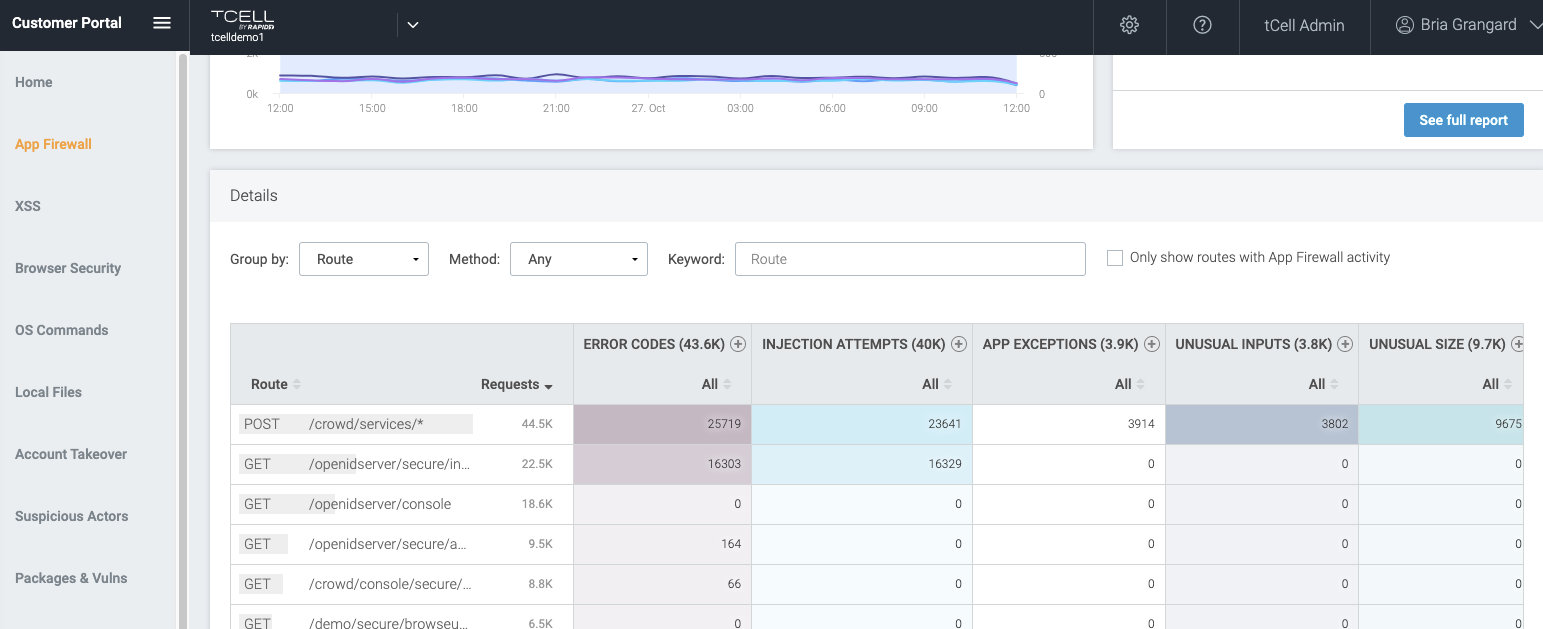
With this new tCell release, customers leveraging .NET or .NET Core frameworks will continue to be supported with our native .NET and .NET Core agents. Additionally, we’ve added functionality for new and existing tCell customers. For those customers who are leveraging tCell’s .NET or .NET Core agents 2.2+, they will now have full visibility into their API endpoints. What’s this mean? tCell will automatically enumerate your application’s API endpoints and show you attack attempts, attack types, and any app exceptions.

tCell by Rapid7 Supports the Newly Released .NET 6.0

This is helpful because it provides visibility into key API endpoints, what attacks were attempted, and what attacks were successful, automatically reducing the number of high alerts our customers receive. From here, customers can drill down for more context on the attack attempts and view detailed stack trace information.

tCell by Rapid7 Supports the Newly Released .NET 6.0

So, tell me more!

In addition to the real-time monitoring and detection for your web applications and APIs, tCell provides a robust set of use cases that it helps solve when leveraging either our .NET or .NET Core agents. Here are just a few examples:

  • Want visibility into your dev teams’ third-party packages and their associated vulnerabilities? Check out our runtime software composition analysis (SCA) feature, which will highlight any vulnerable third party code.
  • Want to make sure no one gets access to your user accounts? Attackers will often use a stolen list of credentials to login to an app and mimic real user behavior. With tCell’s Account Takeover capabilities, we monitor for these auth events and can take action on blocking anyone that is deemed a threat. We can also share a list of compromised users your team can follow up on.
  • Want to ensure your apps only load specific content? tCell makes it seamless and easy to enable Content Security Policies to enforce what content is loaded on your site and ensure a safe and happy user experience.
  • … And so much more, from specific actor detection to prevention of unauthorized executions of OS commands and app-level attacks.

We’re proud of our continued investment in helping customers secure their applications and APIs. Curious to learn more? Feel free to reach out to get a demo of tCell or try it out yourself!

Hacking the Sony Playstation 5

Post Syndicated from Bruce Schneier original https://www.schneier.com/blog/archives/2021/11/hacking-the-sony-playstation-5.html

I just don’t think it’s possible to create a hack-proof computer system, especially when the system is physically in the hands of the hackers. The Sony Playstation 5 is the latest example:

Hackers may have just made some big strides towards possibly jailbreaking the PlayStation 5 over the weekend, with the hacking group Fail0verflow claiming to have managed to obtain PS5 root keys allowing them to decrypt the console’s firmware.

[…]

The two exploits are particularly notable due to the level of access they theoretically give to the PS5’s software. Decrypted firmware ­ which is possible through Fail0verflow’s keys ­ would potentially allow for hackers to further reverse engineer the PS5 software and potentially develop the sorts of hacks that allowed for things like installing Linux, emulators, or even pirated games on past Sony consoles.

In 1999, Adam Shostack and I wrote a paper discussing the security challenges of giving people devices that included embedded secrets that needed to be kept from those people. We were writing about smart cards, but our lessons were general. And they’re no less applicable today.

Implementing interruption tolerance in Amazon EC2 Spot with AWS Fault Injection Simulator

Post Syndicated from Pranaya Anshu original https://aws.amazon.com/blogs/compute/implementing-interruption-tolerance-in-amazon-ec2-spot-with-aws-fault-injection-simulator/

This post is written by Steve Cole, WW SA Leader for EC2 Spot, and David Bermeo, Senior Product Manager for EC2.

On October 20, 2021, AWS released new functionality to the Amazon Fault Injection Simulator that supports triggering the interruption of Amazon EC2 Spot Instances. This functionality lets you test the fault tolerance of your software by interrupting instances on command. The triggered interruption will be preceded with a Rebalance Recommendation (RBR) and Instance Termination Notification (ITN) so that you can fully test your applications as if an actual Spot interruption had occurred.

In this post, we’ll provide two examples of how easy it has now become to simulate Spot interruptions and validate the fault-tolerance of an application or service. We will demonstrate testing an application through the console and a service via CLI.

Engineering use-case (console)

Whether you are building a Spot-capable product or service from scratch or evaluating the Spot compatibility of existing software, the first step in testing is identifying whether or not the software is tolerant of being interrupted.

In the past, one way this was accomplished was with an AWS open-source tool called the Amazon EC2 Metadata Mock. This tool let customers simulate a Spot interruption as if it had been delivered through the Instance Metadata Service (IMDS), which then let customers test how their code responded to an RBR or an ITN. However, this model wasn’t a direct plug-and-play solution with how an actual Spot interruption would occur, since the signal wasn’t coming from AWS. In particular, the method didn’t provide the centralized notifications available through Amazon EventBridge or Amazon CloudWatch Events that enabled off-instance activities like launching AWS Lambda functions or other orchestration work when an RBR or ITN was received.

Now, Fault Injection Simulator has removed the need for custom logic, since it lets RBR and ITN signals be delivered via the standard IMDS and event services simultaneously.

Let’s walk through the process in the AWS Management Console. We’ll identify an instance that’s hosting a perpetually-running queue worker that checks the IMDS before pulling messages from Amazon Simple Queue Service (SQS). It will be part of a service stack that is scaled in and out based on the queue depth. Our goal is to make sure that the IMDS is being polled properly so that no new messages are pulled once an ITN is received. The typical processing time of a message with this example is 30 seconds, so we can wait for an ITN (which provides a two minute warning) and need not act on an RBR.

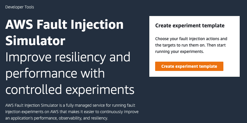
First, we go to the Fault Injection Simulator in the AWS Management Console to create an experiment.

AWS Fault Injection Simulator start screen in AWS Management console

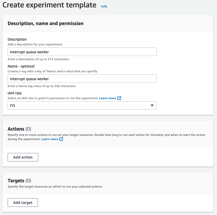
At the experiment creation screen, we start by creating an optional name (recommended for console use) and a description, and then selecting an IAM Role. If this is the first time that you’ve used Fault Injection Simulator, then you’ll need to create an IAM Role per the directions in the FIS IAM permissions documentation. I’ve named the role that we created ‘FIS.’ After that, I’ll select an action (interrupt) and identify a target (the instance).

Experiment template screen in AWS Management console with description “interrupt queue worker,” name “interrupt queue worker,” and IAM role “FIS.”

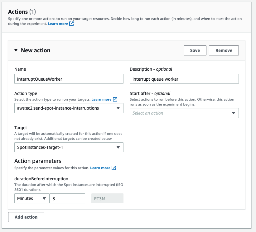
First, I name the action. The Action type I want is to interrupt the Spot Instance: aws:ec2:send-spot-instance-interruptions. In the Action parameters, we are given the option to set the duration. The minimum value here is two minutes, below which you will receive an error since Spot Instances will always receive a two minute warning. The advantage here is that, by setting the durationBeforeInterruption to a value above two minutes, you will get the RBR (an optional point for you to respond) and ITN (the actual two minute warning) at different points in time, and this lets you respond to one or both.

New action form in the create experiment template screen with name, description, action type and durationBeforeInterruption fields filled.

The target instance that we launched is depicted in the following screenshot. It is a Spot Instance that was launched as a persistent request with its interruption action set to ‘stop’ instead of ‘terminate.’ The option to stop a Spot Instance, introduced in 2020, will let us restart the instance, log in and retrieve logs, update code, and perform other work necessary to implement Spot interruption handling.

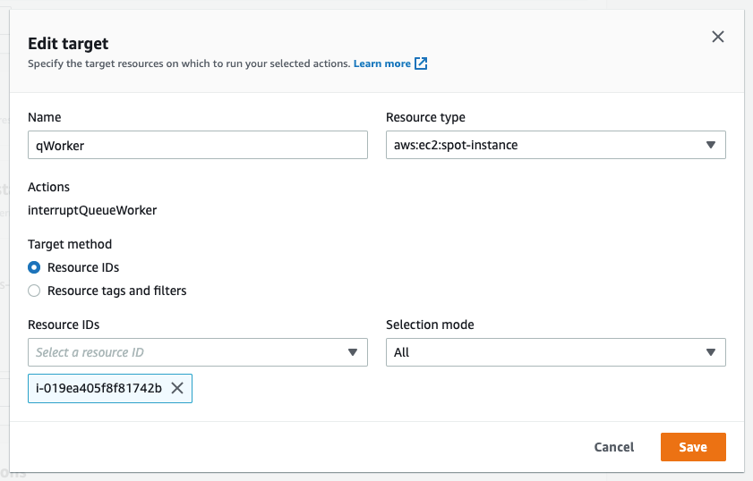
Now that an action has been defined, we configure the target. We have the option of naming the target, which we’ve done here to match the Name tagged on the EC2 instance ‘qWorker’. The target method we want to use here is Resource ID, and then we can either type or select the desired instance from a drop-down list. Selection mode will be ‘all’, as there is only one instance. If we were using tags, which we will in the next example, then we’d be able to select a count of instances, up to five, instead of just one.

Edit target form in the create experiment template screen with name, resource type, and resource id fields filled. Name is “qWorker,” Resource type is “aws:ec2:spot-Instance,” Target method is “Resource IDs” Resource IDs is “i-019ea405f8f81742b” and Selection mode is “All.”

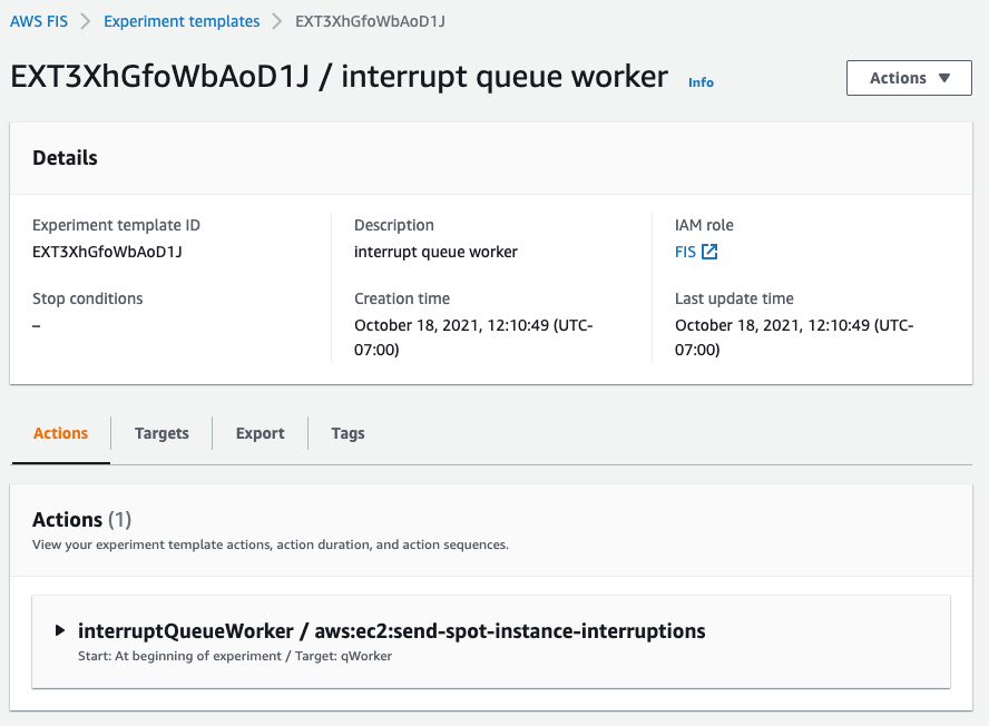
Once you’ve saved the Action, the Target, and the Experiment, then you’ll be able to begin the experiment by selecting the ‘Start from the Action’ menu at the top right of the screen.

Fault Injection Simulator Experiment template summary screen in the AWS Management console highlights experiment template ID, stop conditions, description, creation time, IAM role, and last update time.

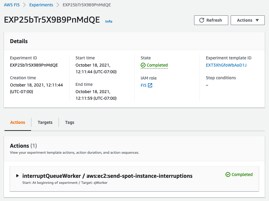
After the experiment starts, you’ll be able to observe its state by refreshing the screen. Generally, the process will take just seconds, and you should be greeted by the Completed state, as seen in the following screenshot.

Fault Injection Simulator Experiment summary screen in the AWS Management console shows status as “Completed.”

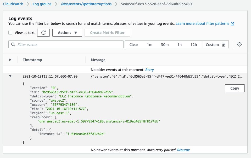
In the following screenshot, having opened an interruption log group created in CloudWatch Event Logs, we can see the JSON of the RBR.

CloudWatch Event Logs screen in the AWS Management Console with information on the EC2 Rebalance Recommendation.

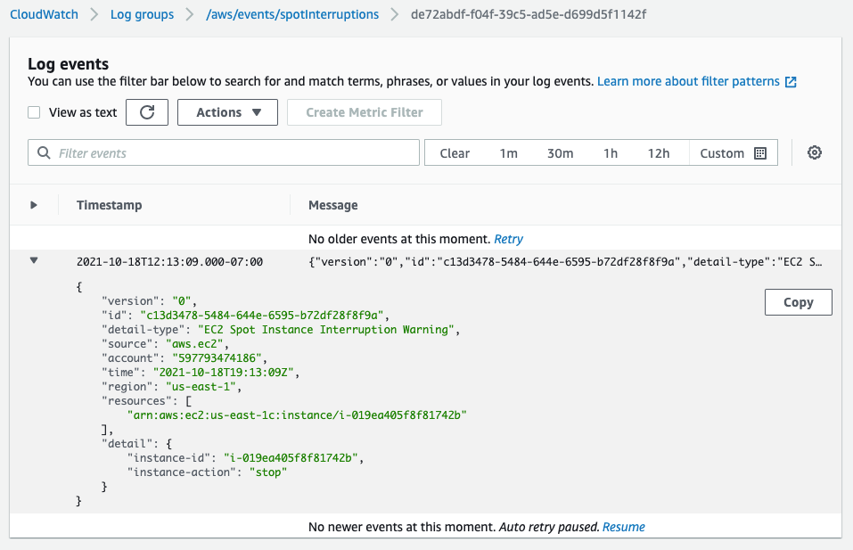
Two minutes later, we see the ITN in the same log group.

Cloudwatch Event Logs screen in the AWS Management console with information on the Instance Termination Notification.

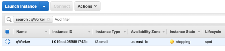
Another two minutes after the ITN, we can see the EC2 instance is in the process of stopping (or terminating, if you elect).

EC2 Instance List screen in the AWS Management console with information on the instance that is stopping.

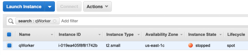
Shortly after the stop is issued by EC2, we can see the instance stopped. It would now be possible to restart the instance and view logs, make code changes, or do whatever you find necessary before testing again.

EC2 Instance List screen in the AWS Management console with information on the Instance that is stopped.

Now that our experiment succeeded in interrupting our Spot Instance, we can evaluate the performance of the code running on the instance. It should have completed the processing of any messages already retrieved at the ITN, and it should have not pulled any new messages afterward.

This experiment can be saved for later use, but it will require selecting the specific instance each time that it’s run. We can also re-use the experiment template by using tags instead of an instance ID, as we’ll show in the next example. This shouldn’t prove troublesome for infrequent experiments, and especially those run through the console. Or, as we did in our example, you can set the instance interruption behavior to stop (versus terminate) and re-use the experiment as long as that particular instance continues to exist. When the experiments get more frequent, it might be advantageous to automate the process, possibly as part of the test phase of a CI/CD pipeline. Doing this is programmatically possible through the AWS CLI or SDK.

Operations use-case (CLI)

Once the developers of our product validate the single-instance fault tolerance, indicating that the target workload is capable of running on Spot Instances, then the next logical step is to deploy the product as a service on multiple instances. This will allow for more comprehensive testing of the service as a whole, and it is a key process in collecting valuable information, such as performance data, response times, error rates, and other metrics to be used in the monitoring of the service. Once data has been collected on a non-interrupted deployment, it is then possible to use the Spot interruption action of the Fault Injection Simulator to observe how well the service can handle RBR and ITN while running, and to see how those events influence the metrics collected previously.

When testing a service, whether it is launched as instances in an Amazon EC2 Auto Scaling group, or it is part of one of the AWS container services, such as Amazon Elastic Container Service (Amazon ECS) or the Amazon Elastic Kubernetes Service (EKS), EC2 Fleet, Amazon EMR, or across any instances with descriptive tagging, you now have the ability to trigger Spot interruptions to as many as five instances in a single Fault Injection Simulator experiment.

We’ll use tags, as opposed to instance IDs, to identify candidates for interruption to interrupt multiple Spot Instances simultaneously. We can further refine the candidate targets with one or more filters in our experiment, for example targeting only running instances if you perform an action repeatedly.

In the following example, we will be interrupting three instances in an Auto Scaling group that is backing a self-managed EKS node group. We already know the software will behave as desired from our previous engineering tests. Our goal here is to see how quickly EKS can launch replacement tasks and identify how the service as a whole responds during the event. In our experiment, we will identify instances that contain the tag aws:autoscaling:groupName with a value of “spotEKS”.

The key benefit here is that we don’t need a list of instance IDs in our experiment. Therefore, this is a re-usable experiment that can be incorporated into test automation without needing to make specific selections from previous steps like collecting instance IDs from the target Auto Scaling group.

We start by creating a file that describes our experiment in JSON rather than through the console:

{
    "description": "interrupt multiple random instances in ASG",
    "targets": {
        "spotEKS": {
            "resourceType": "aws:ec2:spot-instance",
            "resourceTags": {
                "aws:autoscaling:groupName": "spotEKS"
            },
            "selectionMode": "COUNT(3)"
        }
    },
    "actions": {
        "interrupt": {
            "actionId": "aws:ec2:send-spot-instance-interruptions",
            "description": "interrupt multiple instances",
            "parameters": {
                "durationBeforeInterruption": "PT4M"
            },
            "targets": {
            "SpotInstances": "spotEKS"
            }
        }
    },
    "stopConditions": [
        {
            "source": "none"
        }
    ],
    "roleArn": "arn:aws:iam::xxxxxxxxxxxx:role/FIS",
    "tags": {
        "Name": "multi-instance"
    }
}

Then we upload the experiment template to Fault Injection Simulator from the command-line.

aws fis create-experiment-template --cli-input-json file://experiment.json

The response we receive returns our template along with an ID, which we’ll need to execute the experiment.

{
    "experimentTemplate": {
        "id": "EXT3SHtpk1N4qmsn",
        ...
    }
}

We then execute the experiment from the command-line using the ID that we were given at template creation.

aws fis start-experiment --experiment-template-id EXT3SHtpk1N4qmsn

We then receive confirmation that the experiment has started.

{
    "experiment": {
        "id": "EXPaFhEaX8GusfztyY",
        "experimentTemplateId": "EXT3SHtpk1N4qmsn",
        "state": {
            "status": "initiating",
            "reason": "Experiment is initiating."
        },
        ...
    }
}

To check the status of the experiment as it runs, which for interrupting Spot Instances is quite fast, we can query the experiment ID for success or failure messages as follows:

aws fis get-experiment --id EXPaFhEaX8GusfztyY

And finally, we can confirm the results of our experiment by listing our instances through EC2. Here we use the following command-line before and after execution to generate pre- and post-experiment output:

aws ec2 describe-instances --filters\
 Name='tag:aws:autoscaling:groupName',Values='spotEKS'\
 Name='instance-state-name',Values='running'\
 | jq .Reservations[].Instances[].InstanceId | sort

We can then compare this to identify which instances were interrupted and which were launched as replacements.

< "i-003c8d95c7b6e3c63"
< "i-03aa172262c16840a"
< "i-02572fa37a61dc319"
---
> "i-04a13406d11a38ca6"
> "i-02723d957dc243981"
> "i-05ced3f71736b5c95"

Summary

In the previous examples, we have demonstrated through the console and command-line how you can use the Spot interruption action in the Fault Injection Simulator to ascertain how your software and service will behave when encountering a Spot interruption. Simulating Spot interruptions will help assess the fault-tolerance of your software and can assess the impact of interruptions in a running service. The addition of events can enable more tooling, and being able to simulate both ITNs and RBRs, along with the Capacity Rebalance feature of Auto scaling groups, now matches the end-to-end experience of an actual AWS interruption. Get started on simulating Spot interruptions in the console.

Token-based authentication for iOS applications with Amazon SNS

Post Syndicated from Talia Nassi original https://aws.amazon.com/blogs/compute/token-based-authentication-for-ios-applications-with-amazon-sns/

This post is co-written by Karen Hong, Software Development Engineer, AWS Messaging.

To use Amazon SNS to send mobile push notifications, you must provide a set of credentials for connecting to the supported push notification service (see prerequisites for push). For the Apple Push Notification service (APNs), SNS now supports using token-based authentication (.p8), in addition to the existing certificate-based method.

You can now use a .p8 file to create or update a platform application resource through the SNS console or programmatically. You can publish messages (directly or from a topic) to platform application endpoints configured for token-based authentication.

In this tutorial, you set up an example iOS application. You retrieve information from your Apple developer account and learn how to register a new signing key. Next, you use the SNS console to set up a platform application and a platform endpoint. Finally, you test the setup and watch a push notification arrive on your device.

Advantages of token-based authentication

Token-based authentication has several benefits compared to using certificates. The first is that you can use the same signing key from multiple provider servers (iOS,VoIP, and MacOS), and you can use one signing key to distribute notifications for all of your company’s application environments (sandbox, production). In contrast, a certificate is only associated with a particular subset of these channels.

A pain point for customers using certificate-based authentication is the need to renew certificates annually, an inconvenient procedure which can lead to production issues when forgotten. Your signing key for token-based authentication, on the other hand, does not expire.

Token-based authentication improves the security of your certificates. Unlike certificate-based authentication, the credential does not transfer. Hence, it is less likely to be compromised. You establish trust through encrypted tokens that are frequently regenerated. SNS manages the creation and management of these tokens.

You configure APNs platform applications for use with both .p8 and .p12 certificates, but only 1 authentication method is active at any given time.

Setting up your iOS application

To use token-based authentication, you must set up your application.

Prerequisites: An Apple developer account

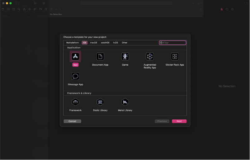
  1. Create a new XCode project. Select iOS as the platform and use the App template.
    xcode project
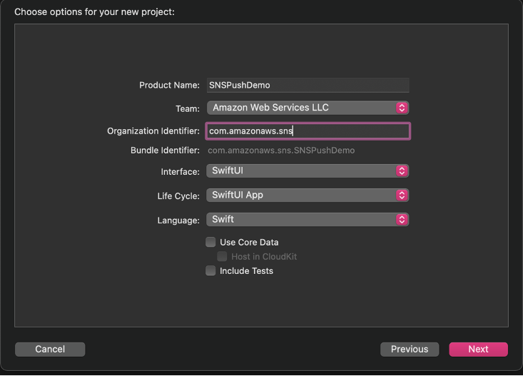
  2. Select your Apple Developer Account team and your organization identifier.
    vscode details
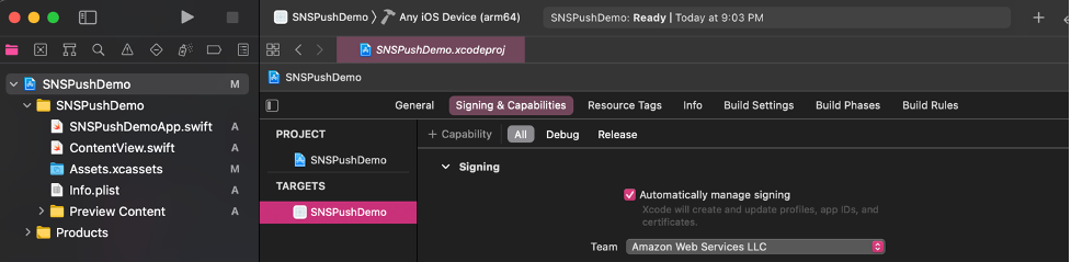
  3. Go to Signing & Capabilities and select + Capability. This step creates resources on your Apple Developer Account.
    step 3
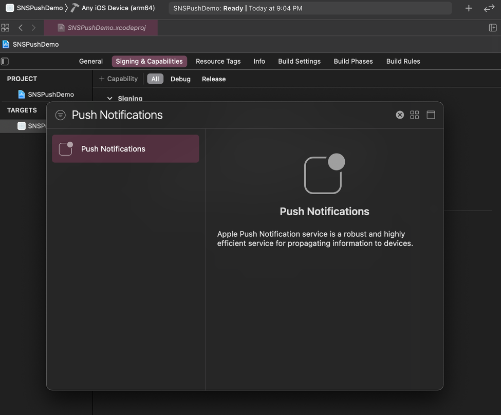
  4. Add the Push Notification Capability.
  5. In SNSPushDemoApp.swift , add the following code to print the device token and receive push notifications.
    import SwiftUI
    
    @main
    struct SNSPushDemoApp: App {
        
        @UIApplicationDelegateAdaptor private var appDelegate: AppDelegate
        
        var body: some Scene {
            WindowGroup {
                ContentView()
            }
        }
    }
    
    class AppDelegate: NSObject, UIApplicationDelegate, UNUserNotificationCenterDelegate {
        
        func application(_ application: UIApplication,
                         didFinishLaunchingWithOptions launchOptions: [UIApplication.LaunchOptionsKey : Any]? = nil) -> Bool {
            UNUserNotificationCenter.current().delegate = self
            return true
        }
        
        func application(_ application: UIApplication,
                         didRegisterForRemoteNotificationsWithDeviceToken deviceToken: Data) {
            let tokenParts = deviceToken.map { data in String(format: "%02.2hhx", data) }
            let token = tokenParts.joined()
            print("Device Token: \(token)")
        };
        
        func application(_ application: UIApplication, didFailToRegisterForRemoteNotificationsWithError error: Error) {
           print(error.localizedDescription)
        }
        
        func userNotificationCenter(_ center: UNUserNotificationCenter, willPresent notification: UNNotification, withCompletionHandler completionHandler: @escaping (UNNotificationPresentationOptions) -> Void) {
            completionHandler([.banner, .badge, .sound])
        }
    }
    
  6. In ContentView.swift, add the code to request authorization for push notifications and register for notifications.
    import SwiftUI
    
    struct ContentView: View {
        init() {
            requestPushAuthorization();
        }
        
        var body: some View {
            Button("Register") {
                registerForNotifications();
            }
        }
    }
    
    struct ContentView_Previews: PreviewProvider {
        static var previews: some View {
            ContentView()
        }
    }
    
    func requestPushAuthorization() {
        UNUserNotificationCenter.current().requestAuthorization(options: [.alert, .badge, .sound]) { success, error in
            if success {
                print("Push notifications allowed")
            } else if let error = error {
                print(error.localizedDescription)
            }
        }
    }
    
    func registerForNotifications() {
        UIApplication.shared.registerForRemoteNotifications()
    }
    
  7. Build and run the app on an iPhone. The push notification feature does not work with a simulator.
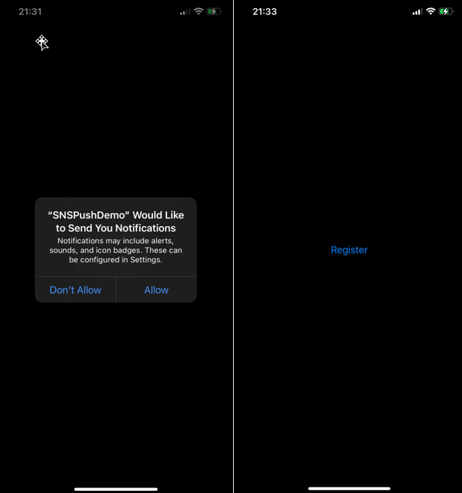
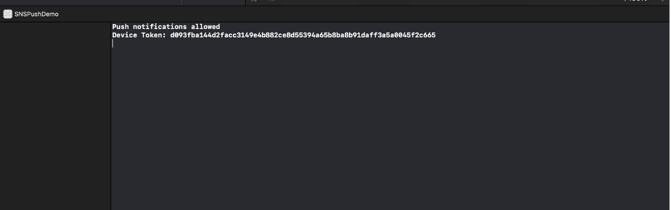
  8. On your phone, select allow notifications when the prompt appears. The debugger prints out “Push notifications allowed” if it is successful.
    allow notifications
  9. On your phone, choose the Register button. The debugger prints out the device token.
  10. You have set up an iOS application that can receive push notifications and prints the device token. We can now use this app to test sending push notifications with SNS configured for token-based authentication.

Retrieving your Apple resources

After setting up your application, you retrieve your Apple resources from your Apple developer account. There are four pieces of information you need from your Apple Developer Account: Bundle ID, Team ID, Signing Key, and Signing Key ID.

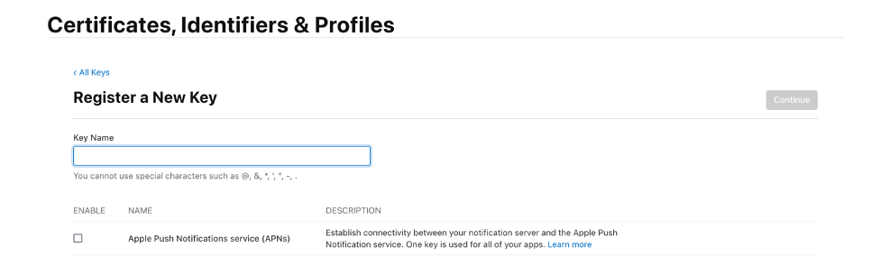
The signing key and signing key ID are credentials that you manage through your Apple Developer Account. You can register a new key by selecting the Keys tab under the Certificates, Identifiers & Profiles menu. Your Apple developer account provides the signing key in the form of a text file with a .p8 extension.

certs

Find the team ID under Membership Details. The bundle ID is the unique identifier that you set up when creating your application. Find this value in the Identifiers section under the Certificates, Identifiers & Profiles menu.

Amazon SNS uses a token constructed from the team ID, signing key, and signing key ID to authenticate with APNs for every push notification that you send. Amazon SNS manages tokens on your behalf and renews them when necessary (within an hour). The request header includes the bundle ID and helps identify where the notification goes.

Creating a new platform application using APNs token-based authentication

Prerequisites

In order to implement APNs token-based authentication, you must have:

  • An Apple Developer Account
  • A mobile application

To create a new platform application:

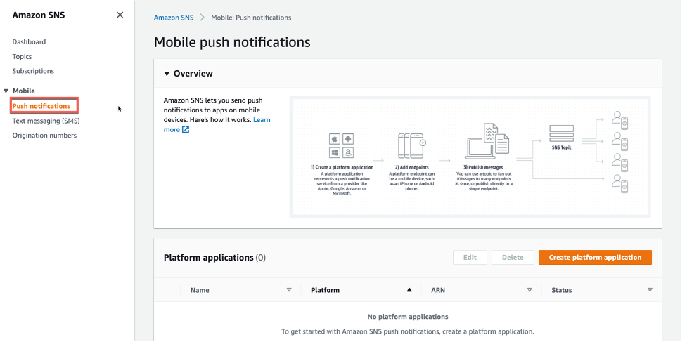
  1. Navigate to the Amazon SNS console and choose Push notifications. Then choose Create platform application.
    sns console
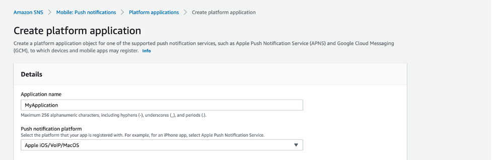
  2. Enter a name for your application. In the Push notification platform dropdown, choose Apple iOS/VoIP/Mac.
    sns name
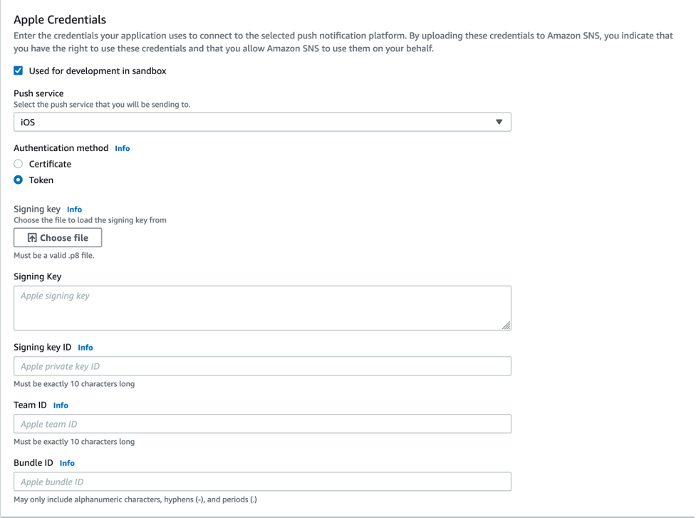
  3. For the Push service, choose iOS, and for the Authentication method, choose Token. Select the check box labeled Used for development in sandbox. Then, input the fields from your Apple Developer Account.
    step 3
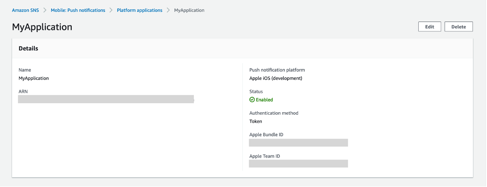
  4. You have successfully created a platform application using APNs token-based authentication.

Creating a new platform endpoint using APNs token-based authentication

A platform application stores credentials, sending configuration, and other settings but does not contain an exact sending destination. Create a platform endpoint resource to store the information to allow SNS to target push notifications to the proper application on the correct mobile device.

Any iOS application that is capable of receiving push notifications must register with APNs. Upon successful registration, APNs returns a device token that uniquely identifies an instance of an app. SNS needs this device token in order to send to that app. Each platform endpoint belongs to a specific platform application and uses the credentials and settings set in the platform application to complete the sending.

In this tutorial, you create the platform endpoint manually through the SNS console. In a real system, upon receiving the device token, you programmatically call SNS from your application server to create or update your platform endpoints.
These are the steps to create a new platform endpoint:

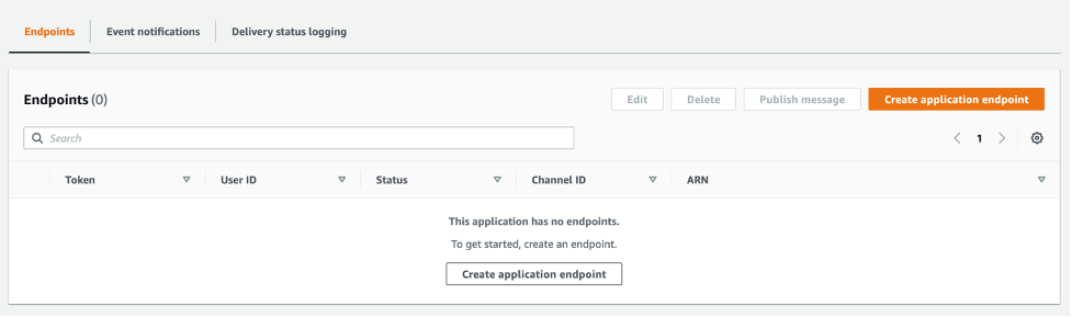
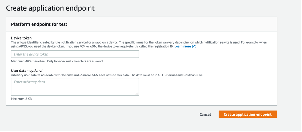
  1. From the details page of the platform application in the SNS console, choose Create application endpoint.
    appliation endpont
  2. From the iOS app that you set up previously, find the device token in the application logs. Enter the device token and choose Create application endpoint.
    application endpont details
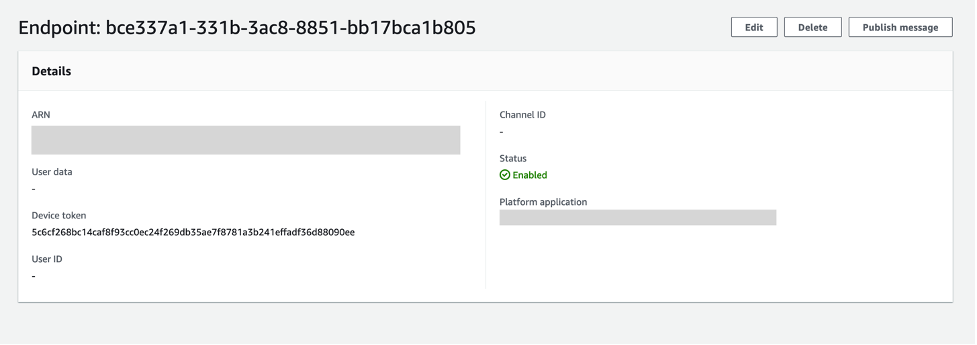
  3. You have successfully created a platform application endpoint.
    application endpoint

Testing a push notification from your device

In this section, you test a push notification from your device.

  1. From the details page of the application endpoint you just created, (this is the page you end up at immediately after creating the endpoint), choose Publish message.
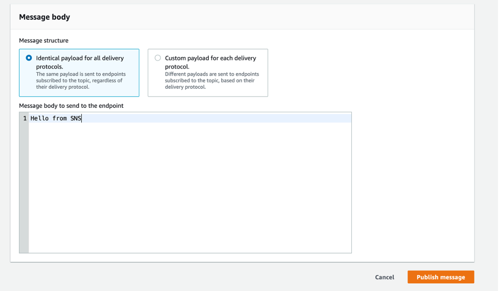
  2. Enter a message to send and choose Publish message.
    testing app
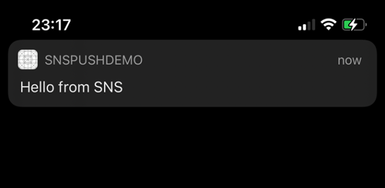
  3. The notification arrives on your iOS app.
    testing the app

Conclusion

Developers sending mobile push notifications can now use a .p8 key to authenticate an Apple device endpoint. Token-based authentication is more secure, and reduces operational burden of renewing the certificates every year. In this post, you learn how to set up your iOS application for mobile push using token-based authentication, by creating and configuring a new platform endpoint in the Amazon SNS console.

To learn more about APNs token-based authentication with Amazon SNS, visit the Amazon SNS Developer Guide. For more serverless content, visit Serverless Land.

Create a serverless event-driven workflow to ingest and process Microsoft data with AWS Glue and Amazon EventBridge

Post Syndicated from Venkata Sistla original https://aws.amazon.com/blogs/big-data/create-a-serverless-event-driven-workflow-to-ingest-and-process-microsoft-data-with-aws-glue-and-amazon-eventbridge/

Microsoft SharePoint is a document management system for storing files, organizing documents, and sharing and editing documents in collaboration with others. Your organization may want to ingest SharePoint data into your data lake, combine the SharePoint data with other data that’s available in the data lake, and use it for reporting and analytics purposes. AWS Glue is a serverless data integration service that makes it easy to discover, prepare, and combine data for analytics, machine learning, and application development. AWS Glue provides all the capabilities needed for data integration so that you can start analyzing your data and putting it to use in minutes instead of months.

Organizations often manage their data on SharePoint in the form of files and lists, and you can use this data for easier discovery, better auditing, and compliance. SharePoint as a data source is not a typical relational database and the data is mostly semi structured, which is why it’s often difficult to join the SharePoint data with other relational data sources. This post shows how to ingest and process SharePoint lists and files with AWS Glue and Amazon EventBridge, which enables you to join other data that is available in your data lake. We use SharePoint REST APIs with a standard open data protocol (OData) syntax. OData advocates a standard way of implementing REST APIs that allows for SQL-like querying capabilities. OData helps you focus on your business logic while building RESTful APIs without having to worry about the various approaches to define request and response headers, query options, and so on.

AWS Glue event-driven workflows

Unlike a traditional relational database, SharePoint data may or may not change frequently, and it’s difficult to predict the frequency at which your SharePoint server generates new data, which makes it difficult to plan and schedule data processing pipelines efficiently. Running data processing frequently can be expensive, whereas scheduling pipelines to run infrequently can deliver cold data. Similarly, triggering pipelines from an external process can increase complexity, cost, and job startup time.

AWS Glue supports event-driven workflows, a capability that lets developers start AWS Glue workflows based on events delivered by EventBridge. The main reason to choose EventBridge in this architecture is because it allows you to process events, update the target tables, and make information available to consume in near-real time. Because frequency of data change in SharePoint is unpredictable, using EventBridge to capture events as they arrive enables you to run the data processing pipeline only when new data is available.

To get started, you simply create a new AWS Glue trigger of type EVENT and place it as the first trigger in your workflow. You can optionally specify a batching condition. Without event batching, the AWS Glue workflow is triggered every time an EventBridge rule matches, which may result in multiple concurrent workflows running. AWS Glue protects you by setting default limits that restrict the number of concurrent runs of a workflow. You can increase the required limits by opening a support case. Event batching allows you to configure the number of events to buffer or the maximum elapsed time before firing the particular trigger. When the batching condition is met, a workflow run is started. For example, you can trigger your workflow when 100 files are uploaded in Amazon Simple Storage Service (Amazon S3) or 5 minutes after the first upload. We recommend configuring event batching to avoid too many concurrent workflows, and optimize resource usage and cost.

To illustrate this solution better, consider the following use case for a wine manufacturing and distribution company that operates across multiple countries. They currently host all their transactional system’s data on a data lake in Amazon S3. They also use SharePoint lists to capture feedback and comments on wine quality and composition from their suppliers and other stakeholders. The supply chain team wants to join their transactional data with the wine quality comments in SharePoint data to improve their wine quality and manage their production issues better. They want to capture those comments from the SharePoint server within an hour and publish that data to a wine quality dashboard in Amazon QuickSight. With an event-driven approach to ingest and process their SharePoint data, the supply chain team can consume the data in less than an hour.

Overview of solution

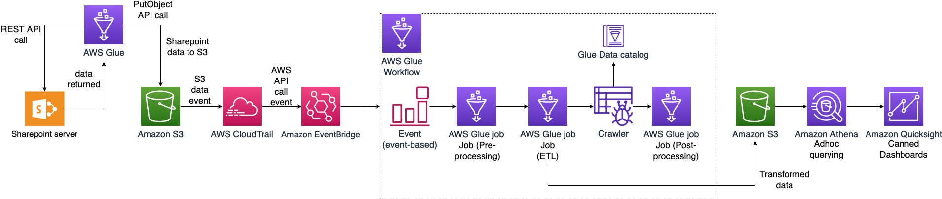
In this post, we walk through a solution to set up an AWS Glue job to ingest SharePoint lists and files into an S3 bucket and an AWS Glue workflow that listens to S3 PutObject data events captured by AWS CloudTrail. This workflow is configured with an event-based trigger to run when an AWS Glue ingest job adds new files into the S3 bucket. The following diagram illustrates the architecture.

To make it simple to deploy, we captured the entire solution in an AWS CloudFormation template that enables you to automatically ingest SharePoint data into Amazon S3. SharePoint uses ClientID and TenantID credentials for authentication and uses Oauth2 for authorization.

The template helps you perform the following steps:

  1. Create an AWS Glue Python shell job to make the REST API call to the SharePoint server and ingest files or lists into Amazon S3.
  2. Create an AWS Glue workflow with a starting trigger of EVENT type.
  3. Configure CloudTrail to log data events, such as PutObject API calls to CloudTrail.
  4. Create a rule in EventBridge to forward the PutObject API events to AWS Glue when they’re emitted by CloudTrail.
  5. Add an AWS Glue event-driven workflow as a target to the EventBridge rule. The workflow gets triggered when the SharePoint ingest AWS Glue job adds new files to the S3 bucket.

Prerequisites

For this walkthrough, you should have the following prerequisites:

Configure SharePoint server authentication details

Before launching the CloudFormation stack, you need to set up your SharePoint server authentication details, namely, TenantID, Tenant, ClientID, ClientSecret, and the SharePoint URL in AWS Systems Manager Parameter Store of the account you’re deploying in. This makes sure that no authentication details are stored in the code and they’re fetched in real time from Parameter Store when the solution is running.

To create your AWS Systems Manager parameters, complete the following steps:

  1. On the Systems Manager console, under Application Management in the navigation pane, choose Parameter Store.
    systems manager
  2. Choose Create Parameter.
  3. For Name, enter the parameter name /DATALAKE/GlueIngest/SharePoint/tenant.
  4. Leave the type as string.
  5. Enter your SharePoint tenant detail into the value field.
  6. Choose Create parameter.
  7. Repeat these steps to create the following parameters:
    1. /DataLake/GlueIngest/SharePoint/tenant
    2. /DataLake/GlueIngest/SharePoint/tenant_id
    3. /DataLake/GlueIngest/SharePoint/client_id/list
    4. /DataLake/GlueIngest/SharePoint/client_secret/list
    5. /DataLake/GlueIngest/SharePoint/client_id/file
    6. /DataLake/GlueIngest/SharePoint/client_secret/file
    7. /DataLake/GlueIngest/SharePoint/url/list
    8. /DataLake/GlueIngest/SharePoint/url/file

Deploy the solution with AWS CloudFormation

For a quick start of this solution, you can deploy the provided CloudFormation stack. This creates all the required resources in your account.

The CloudFormation template generates the following resources:

  • S3 bucket – Stores data, CloudTrail logs, job scripts, and any temporary files generated during the AWS Glue extract, transform, and load (ETL) job run.
  • CloudTrail trail with S3 data events enabled – Enables EventBridge to receive PutObject API call data in a specific bucket.
  • AWS Glue Job – A Python shell job that fetches the data from the SharePoint server.
  • AWS Glue workflow – A data processing pipeline that is comprised of a crawler, jobs, and triggers. This workflow converts uploaded data files into Apache Parquet format.
  • AWS Glue database – The AWS Glue Data Catalog database that holds the tables created in this walkthrough.
  • AWS Glue table – The Data Catalog table representing the Parquet files being converted by the workflow.
  • AWS Lambda function – The AWS Lambda function is used as an AWS CloudFormation custom resource to copy job scripts from an AWS Glue-managed GitHub repository and an AWS Big Data blog S3 bucket to your S3 bucket.
  • IAM roles and policies – We use the following AWS Identity and Access Management (IAM) roles:
    • LambdaExecutionRole – Runs the Lambda function that has permission to upload the job scripts to the S3 bucket.
    • GlueServiceRole – Runs the AWS Glue job that has permission to download the script, read data from the source, and write data to the destination after conversion.
    • EventBridgeGlueExecutionRole – Has permissions to invoke the NotifyEvent API for an AWS Glue workflow.
    • IngestGlueRole – Runs the AWS Glue job that has permission to ingest data into the S3 bucket.

To launch the CloudFormation stack, complete the following steps:

  1. Sign in to the AWS CloudFormation console.

  2. Choose Launch Stack:
  3. Choose Next.
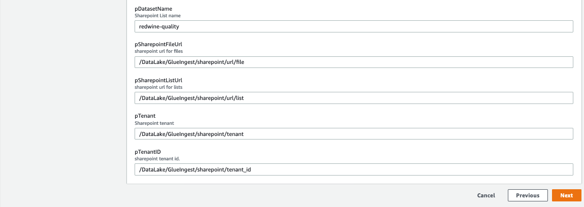
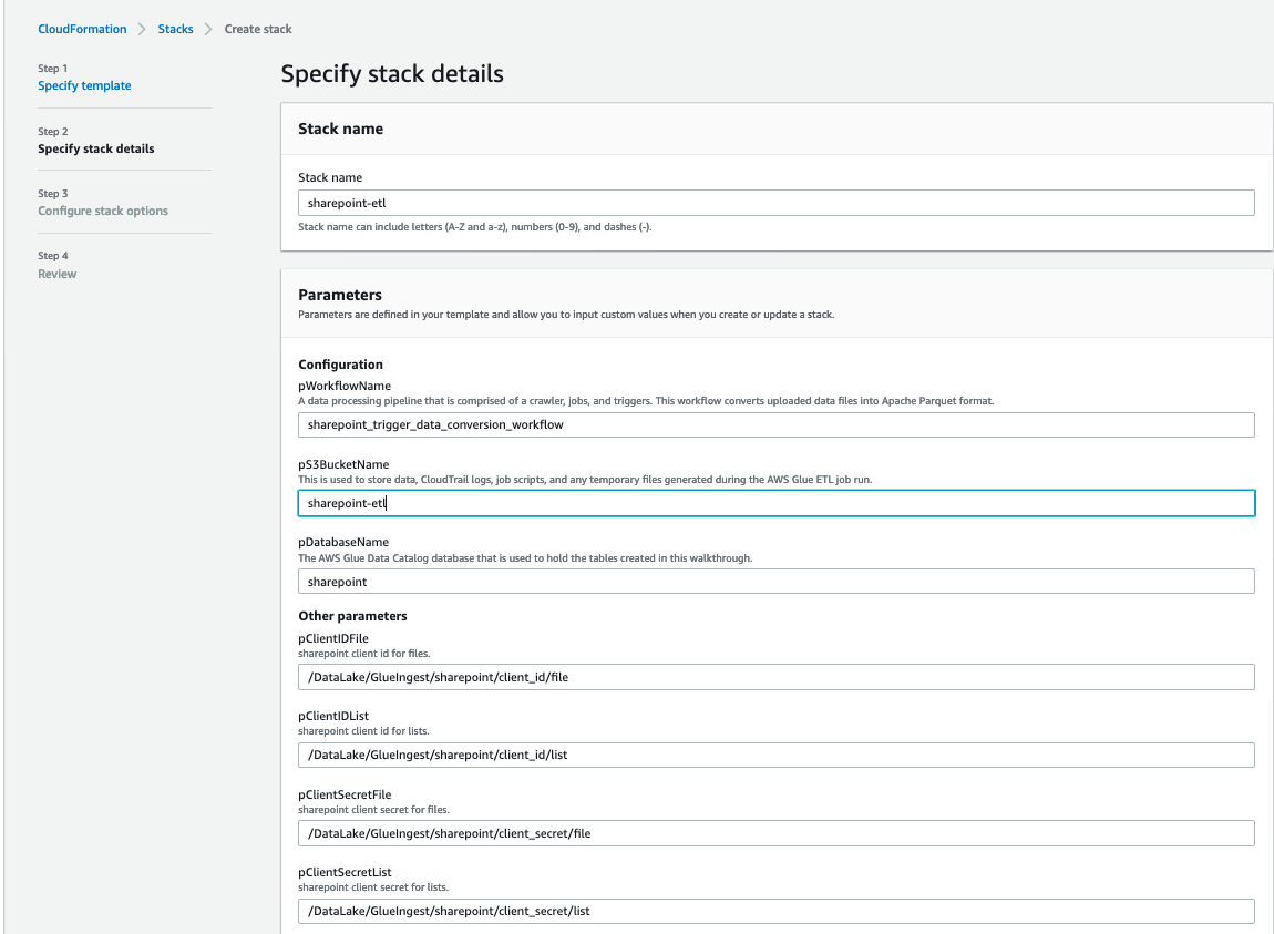
  4. For pS3BucketName, enter the unique name of your new S3 bucket.
  5. Leave pWorkflowName and pDatabaseName as the default.

cloud formation 1

  1. For pDatasetName, enter the SharePoint list name or file name you want to ingest.
  2. Choose Next.

cloud formation 2

  1. On the next page, choose Next.
  2. Review the details on the final page and select I acknowledge that AWS CloudFormation might create IAM resources.
  3. Choose Create.

It takes a few minutes for the stack creation to complete; you can follow the progress on the Events tab.

You can run the ingest AWS Glue job either on a schedule or on demand. As the job successfully finishes and ingests data into the raw prefix of the S3 bucket, the AWS Glue workflow runs and transforms the ingested raw CSV files into Parquet files and loads them into the transformed prefix.

Review the EventBridge rule

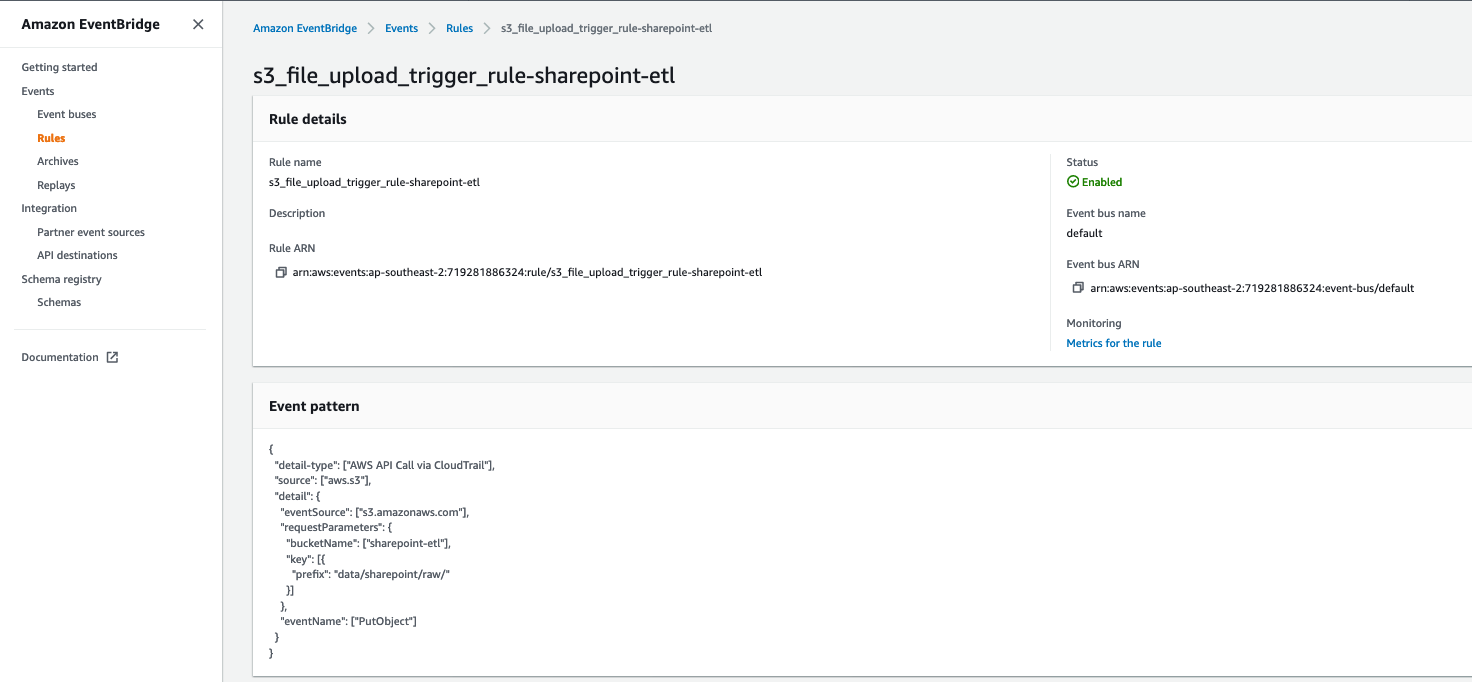
The CloudFormation template created an EventBridge rule to forward S3 PutObject API events to AWS Glue. Let’s review the configuration of the EventBridge rule:

  1. On the EventBridge console, under Events, choose Rules.
  2. Choose the rule s3_file_upload_trigger_rule-<CloudFormation-stack-name>.
  3. Review the information in the Event pattern section.

event bridge

The event pattern shows that this rule is triggered when an S3 object is uploaded to s3://<bucket_name>/data/SharePoint/tablename_raw/. CloudTrail captures the PutObject API calls made and relays them as events to EventBridge.

  1. In the Targets section, you can verify that this EventBridge rule is configured with an AWS Glue workflow as a target.

event bridge target section

Run the ingest AWS Glue job and verify the AWS Glue workflow is triggered successfully

To test the workflow, we run the ingest-glue-job-SharePoint-file job using the following steps:

  1. On the AWS Glue console, select the ingest-glue-job-SharePoint-file job.

glue job

  1. On the Action menu, choose Run job.

glue job action menu

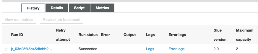
  1. Choose the History tab and wait until the job succeeds.

glue job history tab

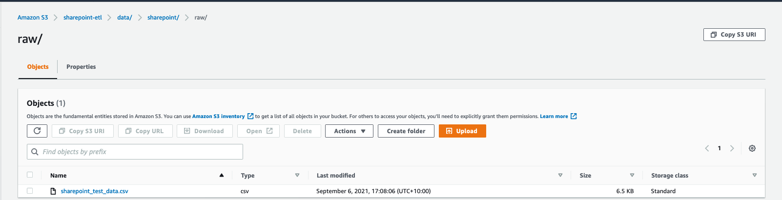
You can now see the CSV files in the raw prefix of your S3 bucket.

csv file s3 location

Now the workflow should be triggered.

  1. On the AWS Glue console, validate that your workflow is in the RUNNING state.

glue workflow running status

  1. Choose the workflow to view the run details.
  2. On the History tab of the workflow, choose the current or most recent workflow run.
  3. Choose View run details.

glue workflow visual

When the workflow run status changes to Completed, let’s check the converted files in your S3 bucket.

  1. Switch to the Amazon S3 console, and navigate to your bucket.

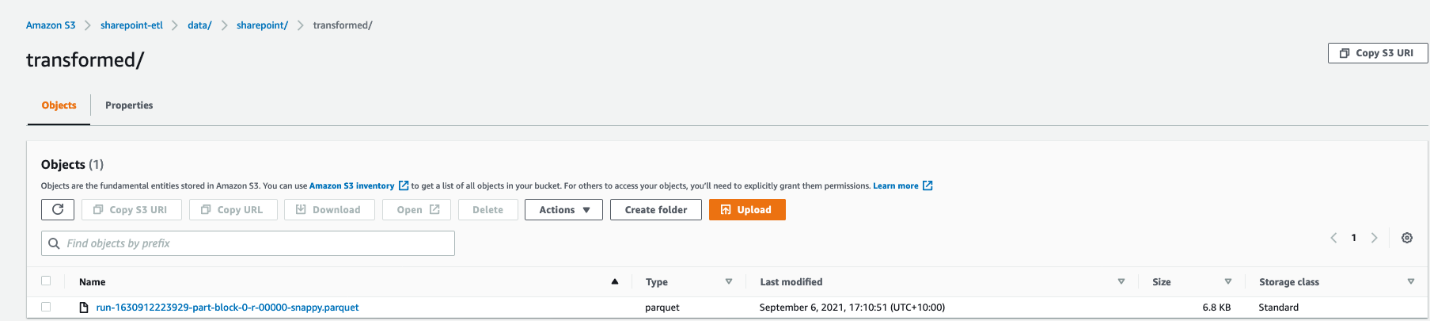
You can see the Parquet files under s3://<bucket_name>/data/SharePoint/tablename_transformed/.

parquet file s3 location

Congratulations! Your workflow ran successfully based on S3 events triggered by uploading files to your bucket. You can verify everything works as expected by running a query against the generated table using Amazon Athena.

Sample wine dataset

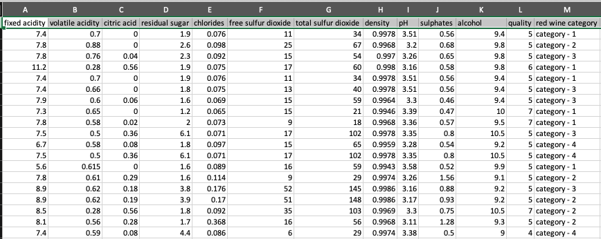
Let’s analyze a sample red wine dataset. The following screenshot shows a SharePoint list that contains various readings that relate to the characteristics of the wine and an associated wine category. This is populated by various wine tasters from multiple countries.

redwine dataset

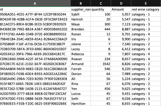
The following screenshot shows a supplier dataset from the data lake with wine categories ordered per supplier.

supplier dataset

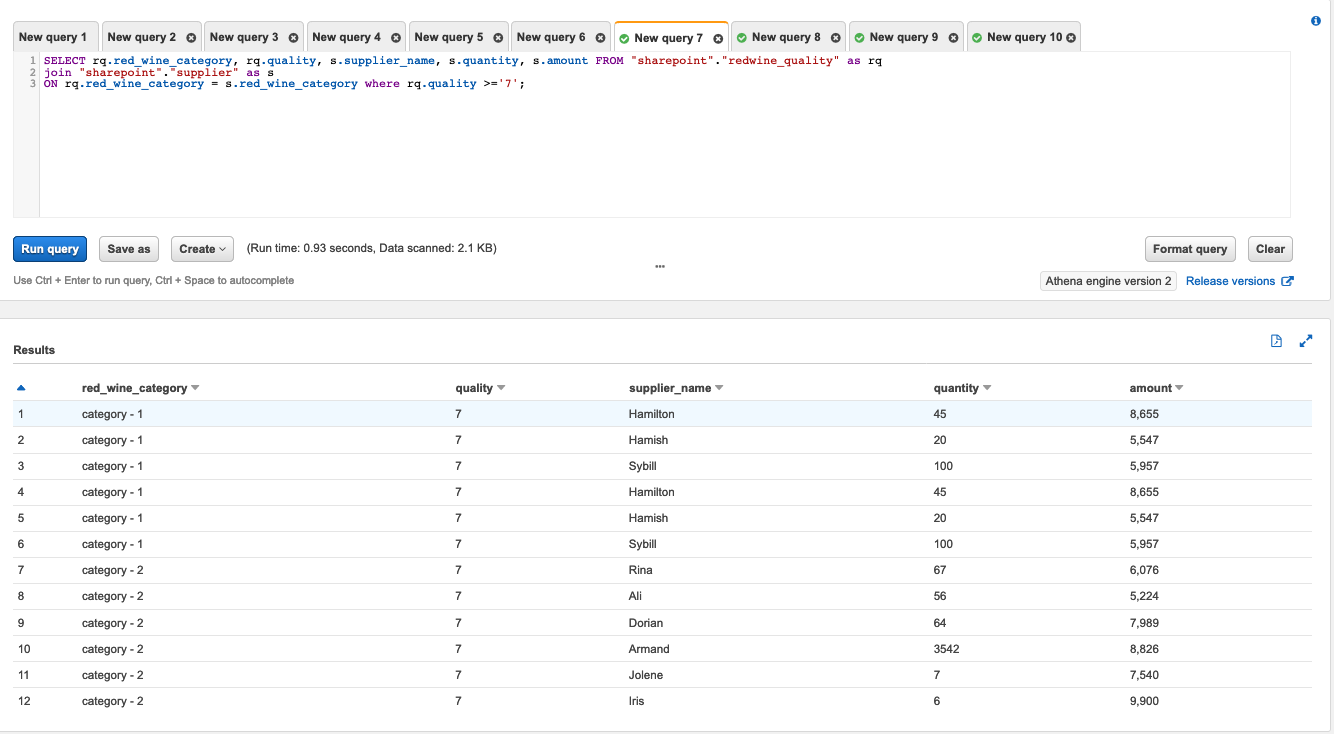
We process the red wine dataset using this solution and use Athena to query the red wine data and supplier data where wine quality is greater than or equal to 7.

athena query and results

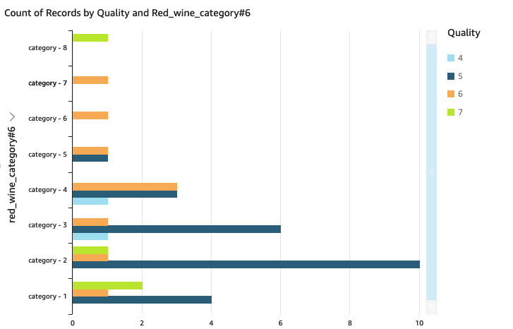
We can visualize the processed dataset using QuickSight.

Clean up

To avoid incurring unnecessary charges, you can use the AWS CloudFormation console to delete the stack that you deployed. This removes all the resources you created when deploying the solution.

Conclusion

Event-driven architectures provide access to near-real-time information and help you make business decisions on fresh data. In this post, we demonstrated how to ingest and process SharePoint data using AWS serverless services like AWS Glue and EventBridge. We saw how to configure a rule in EventBridge to forward events to AWS Glue. You can use this pattern for your analytical use cases, such as joining SharePoint data with other data in your lake to generate insights, or auditing SharePoint data and compliance requirements.


About the Author

Venkata Sistla is a Big Data & Analytics Consultant on the AWS Professional Services team. He specializes in building data processing capabilities and helping customers remove constraints that prevent them from leveraging their data to develop business insights.

Bringing AV1 Streaming to Netflix Members’ TVs

Post Syndicated from Netflix Technology Blog original https://netflixtechblog.com/bringing-av1-streaming-to-netflix-members-tvs-b7fc88e42320

by Liwei Guo, Ashwin Kumar Gopi Valliammal, Raymond Tam, Chris Pham, Agata Opalach, Weibo Ni

AV1 is the first high-efficiency video codec format with a royalty-free license from Alliance of Open Media (AOMedia), made possible by wide-ranging industry commitment of expertise and resources. Netflix is proud to be a founding member of AOMedia and a key contributor to the development of AV1. The specification of AV1 was published in 2018. Since then, we have been working hard to bring AV1 streaming to Netflix members.

In February 2020, Netflix started streaming AV1 to the Android mobile app. The Android launch leveraged the open-source software decoder dav1d built by the VideoLAN, VLC, and FFmpeg communities and sponsored by AOMedia. We were very pleased to see that AV1 streaming improved members’ viewing experience, particularly under challenging network conditions.

While software decoders enable AV1 playback for more powerful devices, a majority of Netflix members enjoy their favorite shows on TVs. AV1 playback on TV platforms relies on hardware solutions, which generally take longer to be deployed.

Throughout 2020 the industry made impressive progress on AV1 hardware solutions. Semiconductor companies announced decoder SoCs for a range of consumer electronics applications. TV manufacturers released TVs ready for AV1 streaming. Netflix has also partnered with YouTube to develop an open-source solution for an AV1 decoder on game consoles that utilizes the additional power of GPUs. It is amazing to witness the rapid growth of the ecosystem in such a short time.

Today we are excited to announce that Netflix has started streaming AV1 to TVs. With this advanced encoding format, we are confident that Netflix can deliver an even more amazing experience to our members. In this techblog, we share some details about our efforts for this launch as well as the benefits we foresee for our members.

Enabling Netflix AV1 Streaming on TVs

Launching a new streaming format on TV platforms is not an easy job. In this section, we list a number of challenges we faced for this launch and share how they have been solved. As you will see, our “highly aligned, loosely coupled” culture played a key role in the success of this cross-functional project. The high alignment guides all teams to work towards the same goals, while the loose coupling keeps each team agile and fast paced.

Challenge 1: What is the best AV1 encoding recipe for Netflix streaming?

AV1 targets a wide range of applications with numerous encoding tools defined in the specification. This leads to unlimited possibilities of encoding recipes and we needed to find the one that works best for Netflix streaming.

Netflix serves movies and TV shows. Production teams spend tremendous effort creating this art, and it is critical that we faithfully preserve the original creative intent when streaming to our members. To achieve this goal, the Encoding Technologies team made the following design decisions about AV1 encoding recipes:

  • We always encode at the highest available source resolution and frame rate. For example, for titles where the source is 4K and high frame rate (HFR) such as “Formula 1: Drive to Survive”, we produce AV1 streams in 4K and HFR. This allows us to present the content exactly as creatively envisioned on devices and plans which support such high resolution and frame-rate playback.
  • All AV1 streams are encoded with 10 bit-depth even if AV1 Main Profile allows both 8 and 10 bit-depth. Almost all movies and TV shows are delivered to Netflix at 10 or higher bit-depth. Using 10-bit encoding can better preserve the creative intent and reduce the chances of artifacts (e.g., banding).
  • Dynamic optimization is used to adapt the recipe at the shot level and intelligently allocate bits. Streams on the Netflix service can easily be watched millions of times, and thus the optimization on the encoding side goes a long way in improving member experience. With dynamic optimization, we allocate more bits to more complex shots to meet Netflix’s high bar of visual quality, while encoding simple shots at the same high quality but with much fewer bits.

Challenge 2: How do we guarantee smooth AV1 playback on TVs?

We have a stream analyzer embedded in our encoding pipeline which ensures that all deployed Netflix AV1 streams are spec-compliant. TVs with an AV1 decoder also need to have decoding capabilities that meet the spec requirement to guarantee smooth playback of AV1 streams.

To evaluate decoder capabilities on these devices, the Encoding Technologies team crafted a set of special certification streams. These streams use the same production encoding recipes so they are representative of production streams, but have the addition of extreme cases to stress test the decoder. For example, some streams have a peak bitrate close to the upper limit allowed by the spec. The Client and UI Engineering team built a certification test with these streams to analyze both the device logs as well as the pictures rendered on the screen. Any issues observed in the test are flagged on a report, and if a gap in the decoding capability was identified, we worked with vendors to bring the decoder up to specification.

Challenge 3: How do we roll out AV1 encoding at Netflix scale?

Video encoding is essentially a search problem — the encoder searches the parameter space allowed by all encoding tools and finds the one that yields the best result. With a larger encoding tool set than previous codecs, it was no surprise that AV1 encoding takes more CPU hours. At the scale that Netflix operates, it is imperative that we use our computational resources efficiently; maximizing the impact of the CPU usage is a key part of AV1 encoding, as is the case with every other codec format.

The Encoding Technologies team took a first stab at this problem by fine-tuning the encoding recipe. To do so, the team evaluated different tools provided by the encoder, with the goal of optimizing the tradeoff between compression efficiency and computational efficiency. With multiple iterations, the team arrived at a recipe that significantly speeds up the encoding with negligible compression efficiency changes.

Besides speeding up the encoder, the total CPU hours could also be reduced if we can use compute resources more efficiently. The Performance Engineering team specializes in optimizing resource utilization at Netflix. Encoding Technologies teamed up with Performance Engineering to analyze the CPU usage pattern of AV1 encoding and based on our findings, Performance Engineering recommended an improved CPU scheduling strategy. This strategy improves encoding throughput by right-sizing jobs based on instance types.

Even with the above improvements, encoding the entire catalog still takes time. One aspect of the Netflix catalog is that not all titles are equally popular. Some titles (e.g., La Casa de Papel) have more viewing than others, and thus AV1 streams of these titles can reach more members. To maximize the impact of AV1 encoding while minimizing associated costs, the Data Science and Engineering team devised a catalog rollout strategy for AV1 that took into consideration title popularity and a number of other factors.

Challenge 4: How do we continuously monitor AV1 streaming?

With this launch, AV1 streaming reaches tens of millions of Netflix members. Having a suite of tools that can provide summarized metrics for these streaming sessions is critical to the success of Netflix AV1 streaming.

The Data Science and Engineering team built a number of dashboards for AV1 streaming, covering a wide range of metrics from streaming quality of experience (“QoE”) to device performance. These dashboards allow us to monitor and analyze trends over time as members stream AV1. Additionally, the Data Science and Engineering team built a dedicated AV1 alerting system which detects early signs of issues in key metrics and automatically sends alerts to teams for further investigation. Given AV1 streaming is at a relatively early stage, these tools help us be extra careful to avoid any negative member experience.

Quality of Experience Improvements

We compared AV1 to other codecs over thousands of Netflix titles, and saw significant compression efficiency improvements from AV1. While the result of this offline analysis was very exciting, what really matters to us is our members’ streaming experience.

To evaluate how the improved compression efficiency from AV1 impacts the quality of experience (QoE) of member streaming, A/B testing was conducted before the launch. Netflix encodes content into multiple formats and selects the best format for a given streaming session by considering factors such as device capabilities and content selection. Therefore, multiple A/B tests were created to compare AV1 with each of the applicable codec formats. In each of these tests, members with eligible TVs were randomly allocated to one of two cells, “control” and “treatment”. Those allocated to the “treatment” cell received AV1 streams while those allocated to the “control” cell received streams of the same codec format as before.

In all of these A/B tests, we observed improvements across many metrics for members in the “treatment” cell, in-line with our expectations:

Higher VMAF scores across the full spectrum of streaming sessions

  • VMAF is a video quality metric developed and open-sourced by Netflix, and is highly correlated to visual quality. Being more efficient, AV1 delivers videos with improved visual quality at the same bitrate, and thus higher VMAF scores.
  • The improvement is particularly significant among sessions that experience serious network congestion and the lowest visual quality. For these sessions, AV1 streaming improves quality by up to 10 VMAF without impacting the rebuffer rate.

More streaming at the highest resolution

  • With higher compression efficiency, the bandwidth needed for streaming is reduced and thus it is easier for playback to reach the highest resolution for that session.
  • For 4K eligible sessions, on average, the duration of 4K videos being streamed increased by about 5%.

Fewer noticeable drops in quality during playback

  • We want our members to have brilliant playback experiences, and our players are designed to adapt to the changing network conditions. When the current condition cannot sustain the current video quality, our players can switch to a lower bitrate stream to reduce the chance of a playback interruption. Given AV1 consumes less bandwidth for any given quality level, our players are able to sustain the video quality for a longer period of time and do not need to switch to a lower bitrate stream as much as before.
  • On some TVs, noticeable drops in quality were reduced by as much as 38%.

Reduced start play delay

  • On some TVs, with the reduced bitrate, the player can reach the target buffer level sooner to start the playback.
  • On average, we observed a 2% reduction in play delay with AV1 streaming.

Next Steps

Our initial launch includes a number of AV1 capable TVs as well as TVs connected with PS4 Pro. We are working with external partners to enable more and more devices for AV1 streaming. Another exciting direction we are exploring is AV1 with HDR. Again, the teams at Netflix are committed to delivering the best picture quality possible to our members. Stay tuned!

Acknowledgments

This is a collective effort with contributions from many of our colleagues at Netflix. We would like to thank

  • Andrey Norkin and Cyril Concolato for providing their insights about AV1 specifications.
  • Kyle Swanson for the work on reducing AV1 encoding complexity.
  • Anush Moorthy and Aditya Mavlankar for fruitful discussions about encoding recipes.
  • Frederic Turmel and his team for managing AV1 certification tests and building tools to automate device verification.
  • Susie Xia for helping improve resource utilization of AV1 encoding.
  • Client teams for integrating AV1 playback support and optimizing the experience.
  • The Partner Engineering team for coordinating with device vendors and investigating playback issues.
  • The Media Cloud Engineering team for accommodating the computing resources for the AV1 rollout.
  • The Media Content Playback team for providing tools for AV1 rollout management.
  • The Data Science and Engineering team for A/B test analysis, and for providing data to help us continuously monitor AV1.

If you are passionate about video technologies and interested in what we are doing at Netflix, come and chat with us! The Encoding Technologies team currently has a number of openings, and we can’t wait to have more stunning engineers joining us.

Senior Software Engineer, Encoding Technologies

Senior Software Engineer, Video & Image Encoding

Senior Software Engineer, Media Systems


Bringing AV1 Streaming to Netflix Members’ TVs was originally published in Netflix TechBlog on Medium, where people are continuing the conversation by highlighting and responding to this story.

[$] Concurrency in Julia

Post Syndicated from original https://lwn.net/Articles/875367/rss

The Julia programming language has
it roots in high-performance scientific computing, so it is no surprise
that it has facilities for concurrent processing. Those features are not
well-known outside of the Julia community, though, so it is interesting to
see the different types of parallel and concurrent computation that the
language supports. In addition, the upcoming release of Julia
version 1.7
brings an improvement to the language’s
concurrent-computation palette,
in the form of “task
migration”.

How Roche democratized access to data with Google Sheets and Amazon Redshift Data API

Post Syndicated from Dr. Yannick Misteli original https://aws.amazon.com/blogs/big-data/how-roche-democratized-access-to-data-with-google-sheets-and-amazon-redshift-data-api/

This post was co-written with Dr. Yannick Misteli, João Antunes, and Krzysztof Wisniewski from the Roche global Platform and ML engineering team as the lead authors.

Roche is a Swiss multinational healthcare company that operates worldwide. Roche is the largest pharmaceutical company in the world and the leading provider of cancer treatments globally.

In this post, Roche’s global Platform and machine learning (ML) engineering team discuss how they used Amazon Redshift data API to democratize access to the data in their Amazon Redshift data warehouse with Google Sheets (gSheets).

Business needs

Go-To-Market (GTM) is the domain that lets Roche understand customers and create and deliver valuable services that meet their needs. This lets them get a better understanding of the health ecosystem and provide better services for patients, doctors, and hospitals. It extends beyond health care professionals (HCPs) to a larger Healthcare ecosystem consisting of patients, communities, health authorities, payers, providers, academia, competitors, etc. Data and analytics are essential to supporting our internal and external stakeholders in their decision-making processes through actionable insights.

For this mission, Roche embraced the modern data stack and built a scalable solution in the cloud.

Driving true data democratization requires not only providing business leaders with polished dashboards or data scientists with SQL access, but also addressing the requirements of business users that need the data. For this purpose, most business users (such as Analysts) leverage Excel—or gSheet in the case of Roche—for data analysis.

Providing access to data in Amazon Redshift to these gSheets users is a non-trivial problem. Without a powerful and flexible tool that lets data consumers use self-service analytics, most organizations will not realize the promise of the modern data stack. To solve this problem, we want to empower every data analyst who doesn’t have an SQL skillset with a means by which they can easily access and manipulate data in the applications that they are most familiar with.

The Roche GTM organization uses the Redshift Data API to simplify the integration between gSheets and Amazon Redshift, and thus facilitate the data needs of their business users for analytical processing and querying. The Amazon Redshift Data API lets you painlessly access data from Amazon Redshift with all types of traditional, cloud-native, and containerized, serverless web service-based applications and event-driven applications. Data API simplifies data access, ingest, and egress from languages supported with AWS SDK, such as Python, Go, Java, Node.js, PHP, Ruby, and C++ so that you can focus on building applications as opposed to managing infrastructure. The process they developed using Amazon Redshift Data API has significantly lowered the barrier for entry for new users without needing any data warehousing experience.

Use-Case

In this post, you will learn how to integrate Amazon Redshift with gSheets to pull data sets directly back into gSheets. These mechanisms are facilitated through the use of the Amazon Redshift Data API and Google Apps Script. Google Apps Script is a programmatic way of manipulating and extending gSheets and the data that they contain.

Architecture

It is possible to include publicly available JS libraries such as JQuery-builder provided that Apps Script is natively a cloud-based Javascript platform.

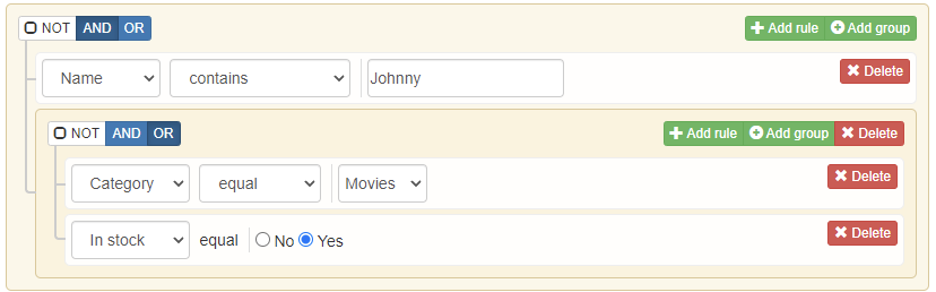
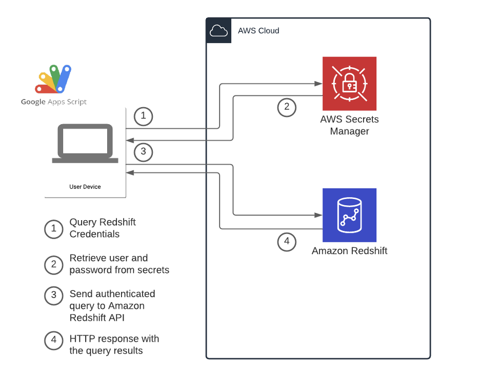
The JQuery builder library facilitates the creation of standard SQL queries via a simple-to-use graphical user interface. The Redshift Data API can be used to retrieve the data directly to gSheets with a query in place. The following diagram illustrates the overall process from a technical standpoint:

Even though AppsScript is, in fact, Javascript, the AWS-provided SDKs for the browser (NodeJS and React) cannot be used on the Google platform, as they require specific properties that are native to the underlying infrastructure. It is possible to authenticate and access AWS resources through the available API calls. Here is an example of how to achieve that.

You can use an access key ID and a secret access key to authenticate the requests to AWS by using the code in the link example above. We recommend following the least privilege principle when granting access to this programmatic user, or assuming a role with temporary credentials. Since each user will require a different set of permissions on the Redshift objects—database, schema, and table—each user will have their own user access credentials. These credentials are safely stored under the AWS Secrets Manager service. Therefore, the programmatic user needs a set of permissions that enable them to retrieve secrets from the AWS Secrets Manager and execute queries against the Redshift Data API.

Code example for AppScript to use Data API

In this section, you will learn how to pull existing data back into a new gSheets Document. This section will not cover how to parse the data from the JQuery-builder library, as it is not within the main scope of the article.

<script src="https://cdn.jsdelivr.net/npm/jQuery-QueryBuilder/dist/js/query-builder.standalone.min.js"></script>    
  1. In the AWS console, go to Secrets Manager and create a new secret to store the database credentials to access the Redshift Cluster: username and password. These will be used to grant Redshift access to the gSheets user.
  2. In the AWS console, create a new IAM user with programmatic access, and generate the corresponding Access Key credentials. The only set of policies required for this user is to be able to read the secret created in the previous step from the AWS Secrets Manager service and to query the Redshift Data API.

    Below is the policy document:

    {
      "Version": "2012-10-17",
      "Statement": [
        {
          "Sid": "VisualEditor0",
          "Effect": "Allow",
          "Action": [
            "secretsmanager:GetSecretValue",
            "secretsmanager:DescribeSecret"
          ],
          "Resource": "arn:aws:secretsmanager:*::secret:*"
        },
        {
          "Sid": "VisualEditor1",
          "Effect": "Allow",
          "Action": "secretsmanager:ListSecrets",
          "Resource": "*"
        },
        {
          "Sid": "VisualEditor2",
          "Effect": "Allow",
          "Action": "redshift-data:*",
          "Resource": "arn:aws:redshift:*::cluster:*"
        }
      ]
    }

  3. Access the Google Apps Script console. Create an aws.gs file with the code available here. This will let you perform authenticated requests to the AWS services by providing an access key and a secret access key.
  4. Initiate the AWS variable providing the access key and secret access key created in step 3.
    AWS.init("<ACCESS_KEY>", "<SECRET_KEY>");

  5. Request the Redshift username and password from the AWS Secrets Manager:
    function runGetSecretValue_(secretId) {
     
      var resultJson = AWS.request(
        	getSecretsManagerTypeAWS_(),
        	getLocationAWS_(),
        	'secretsmanager.GetSecretValue',
        	{"Version": getVersionAWS_()},
        	method='POST',
        	payload={          
          	"SecretId" : secretId
        	},
        	headers={
          	"X-Amz-Target": "secretsmanager.GetSecretValue",
          	"Content-Type": "application/x-amz-json-1.1"
        	}
      );
     
      Logger.log("Execute Statement result: " + resultJson);
      return JSON.parse(resultJson);
     
    }

  6. Query a table using the Amazon Redshift Data API:
    function runExecuteStatement_(sql) {
     
      var resultJson = AWS.request(
        	getTypeAWS_(),
        	getLocationAWS_(),
        	'RedshiftData.ExecuteStatement',
        	{"Version": getVersionAWS_()},
        	method='POST',
        	payload={
          	"ClusterIdentifier": getClusterIdentifierReshift_(),
          	"Database": getDataBaseRedshift_(),
          	"DbUser": getDbUserRedshift_(),
          	"Sql": sql
        	},
        	headers={
          	"X-Amz-Target": "RedshiftData.ExecuteStatement",
          	"Content-Type": "application/x-amz-json-1.1"
        	}
      ); 
     
      Logger.log("Execute Statement result: " + resultJson); 

  7. The result can then be displayed as a table in gSheets:
    function fillGsheet_(recordArray) { 
     
      adjustRowsCount_(recordArray);
     
      var rowIndex = 1;
      for (var i = 0; i < recordArray.length; i++) {  
           
    	var rows = recordArray[i];
    	for (var j = 0; j < rows.length; j++) {
      	var columns = rows[j];
      	rowIndex++;
      	var columnIndex = 'A';
         
      	for (var k = 0; k < columns.length; k++) {
           
        	var field = columns[k];       
        	var value = getFieldValue_(field);
        	var range = columnIndex + rowIndex;
        	addToCell_(range, value);
     
        	columnIndex = nextChar_(columnIndex);
     
      	}
     
    	}
     
      }
     
    }

  8. Once finished, the Apps Script can be deployed as an Addon that enables end-users from an entire organization to leverage the capabilities of retrieving data from Amazon Redshift directly into their spreadsheets. Details on how Apps Script code can be deployed as an Addon can be found here.

How users access Google Sheets

  1. Open a gSheet, and go to manage addons -> Install addon:
  2. Once the Addon is successfully installed, select the Addon menu and select Redshift Synchronization. A dialog will appear prompting the user to select the combination of database, schema, and table from which to load the data.
  3. After choosing the intended table, a new panel will appear on the right side of the screen. Then, the user is prompted to select which columns to retrieve from the table, apply any filtering operation, and/or apply any aggregations to the data.
  4. Upon submitting the query, app scripts will translate the user selection into a query that is sent to the Amazon Redshift Data API. Then, the returned data is transformed and displayed as a regular gSheet table:

Security and Access Management

In the scripts above, there is a direct integration between AWS Secrets Manager and Google Apps Script. The scripts above can extract the currently-authenticated user’s Google email address. Using this value and a set of annotated tags, the script can appropriately pull the user’s credentials securely to authenticate the requests made to the Amazon Redshift cluster. Follow these steps to set up a new user in an existing Amazon Redshift cluster. Once the user has been created, follow these steps for creating a new AWS Secrets Manager secret for your cluster. Make sure that the appropriate tag is applied with the key of “email” along with the corresponding user’s Google email address. Here is a sample configuration that is used for creating Redshift groups, users, and data shares via the Redshift Data API:

connection:
 redshift_super_user_database: dev
 redshift_secret_name: dev_
 redshift_cluster_identifier: dev-cluster
 redshift_secrets_stack_name: dev-cluster-secrets
 environment: dev
 aws_region: eu-west-1
 tags:
   - key: "Environment"
 	value: "dev"
users:
 - name: user1
   email: [email protected]
 data_shares:
 - name: test_data_share
   schemas:
 	- schema1
   redshift_namespaces:
 	- USDFJIL234234WE
group:
 - name: readonly
   users:
 	- user1
   databases:
 	- database: database1
   	exclude-schemas:
     	- public
     	- pg_toast
     	- catalog_history
   	include-schemas:
     	- schema1
   	grant:
     	- select

Operational Metrics and Improvement

Providing access to live data that is hosted in Redshift directly to the business users and enabling true self-service decrease the burden on platform teams to provide data extracts or other mechanisms to deliver up-to-date information. Additionally, by not having different files and versions of data circulating, the business risk of reporting different key figures or KPI can be reduced, and an overall process efficiency can be achieved.

The initial success of this add-on in GTM led to the extension of this to a broader audience, where we are hoping to serve hundreds of users with all of the internal and public data in the future.

Conclusion

In this post, you learned how to create new Amazon Redshift tables and pull existing Redshift tables into a Google Sheet for business users to easily integrate with and manipulate data. This integration was seamless and demonstrated how easy the Amazon Redshift Data API makes integration with external applications, such as Google Sheets with Amazon Redshift. The outlined use-cases above are just a few examples of how the Amazon Redshift Data API can be applied and used to simplify interactions between users and Amazon Redshift clusters.


About the Authors

Dr. Yannick Misteli is leading cloud platform and ML engineering teams in global product strategy (GPS) at Roche. He is passionate about infrastructure and operationalizing data-driven solutions, and he has broad experience in driving business value creation through data analytics.

João Antunes is a Data Engineer in the Global Product Strategy (GPS) team at Roche. He has a track record of deploying Big Data batch and streaming solutions for the telco, finance, and pharma industries.

Krzysztof Wisniewski is a back-end JavaScript developer in the Global Product Strategy (GPS) team at Roche. He is passionate about full-stack development from the front-end through the back-end to databases.

Matt Noyce is a Senior Cloud Application Architect at AWS. He works together primarily with Life Sciences and Healthcare customers to architect and build solutions on AWS for their business needs.

Debu Panda, a Principal Product Manager at AWS, is an industry leader in analytics, application platform, and database technologies, and has more than 25 years of experience in the IT world. Debu has published numerous articles on analytics, enterprise Java, and databases and has presented at multiple conferences such as re:Invent, Oracle Open World, and Java One. He is lead author of the EJB 3 in Action (Manning Publications 2007, 2014) and Middleware Management (Packt).

Migrating to an Amazon Redshift Cloud Data Warehouse from Microsoft APS

Post Syndicated from Sudarshan Roy original https://aws.amazon.com/blogs/architecture/migrating-to-an-amazon-redshift-cloud-data-warehouse-from-microsoft-aps/

Before cloud data warehouses (CDWs), many organizations used hyper-converged infrastructure (HCI) for data analytics. HCIs pack storage, compute, networking, and management capabilities into a single “box” that you can plug into your data centers. However, because of its legacy architecture, an HCI is limited in how much it can scale storage and compute and continue to perform well and be cost-effective. Using an HCI can impact your business’s agility because you need to plan in advance, follow traditional purchase models, and maintain unused capacity and its associated costs. Additionally, HCIs are often proprietary and do not offer the same portability, customization, and integration options as with open-standards-based systems. Because of their proprietary nature, migrating HCIs to a CDW can present technical hurdles, which can impact your ability to realize the full potential of your data.

One of these hurdles includes using AWS Schema Conversion Tool (AWS SCT). AWS SCT is used to migrate data warehouses, and it supports several conversions. However, when you migrate Microsoft’s Analytics Platform System (APS) SQL Server Parallel Data Warehouse (PDW) platform using only AWS SCT, it results in connection errors due to the lack of server-side cursor support in Microsoft APS. In this blog post, we show you three approaches that use AWS SCT combined with other AWS services to migrate Microsoft’s Analytics Platform System (APS) SQL Server Parallel Data Warehouse (PDW) HCI platform to Amazon Redshift. These solutions will help you overcome elasticity, scalability, and agility constraints associated with proprietary HCI analytics platforms and future proof your analytics investment.

AWS Schema Conversion Tool

Though using AWS SCT only will result in server-side cursor errors, you can pair it with other AWS services to migrate your data warehouses to AWS. AWS SCT converts source database schema and code objects, including views, stored procedures, and functions, to be compatible with a target database. It highlights objects that require manual intervention. You can also scan your application source code for embedded SQL statements as part of database-schema conversion project. During this process, AWS SCT optimizes cloud-native code by converting legacy Oracle and SQL Server functions to their equivalent AWS service. This helps you modernize applications simultaneously. Once conversion is complete, AWS SCT can also migrate data.

Figure 1 shows a standard AWS SCT implementation architecture.

AWS SCT migration approach

Figure 1. AWS SCT migration approach

The next section shows you how to pair AWS SCT with other AWS services to migrate a Microsoft APS PDW to Amazon Redshift CDW. We prove you a base approach and two extensions to use for data warehouses with larger datasets and longer release outage windows.

Migration approach using SQL Server on Amazon EC2

The base approach uses Amazon Elastic Compute Cloud (Amazon EC2) to host a SQL Server in a symmetric multi-processing (SMP) architecture that is supported by AWS SCT, as opposed to Microsoft’s APS PDW’s massively parallel processing (MPP) architecture. By changing the warehouse’s architecture from MPP to SMP and using AWS SCT, you’ll avoid server-side cursor support errors.

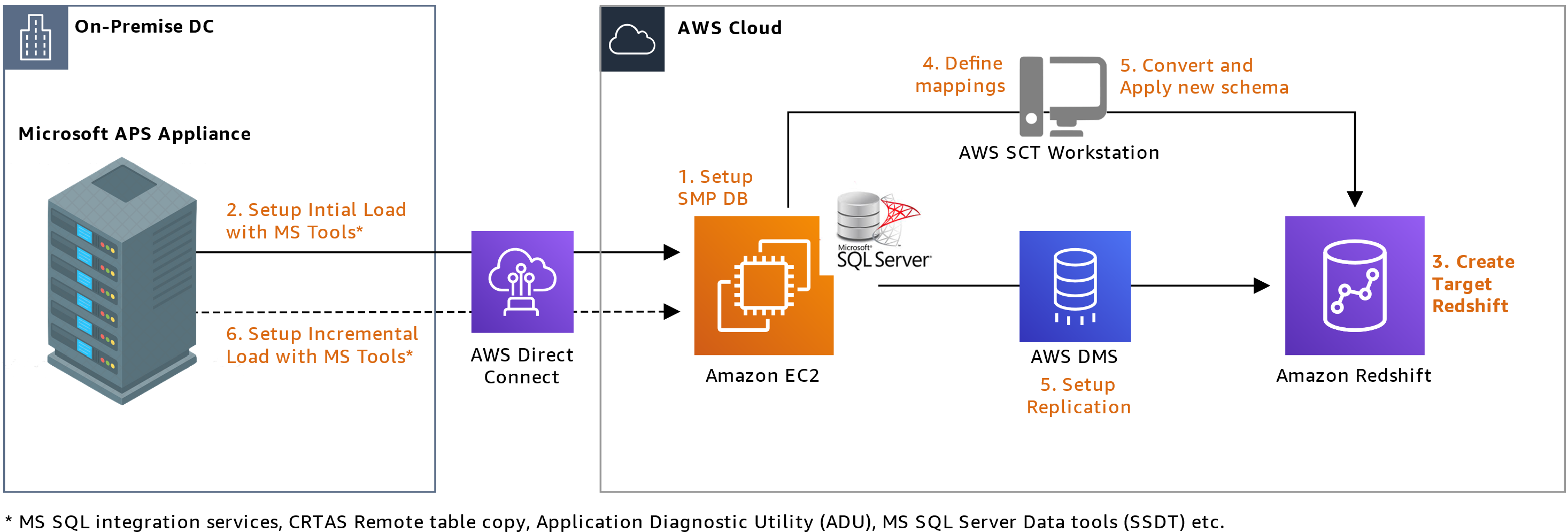
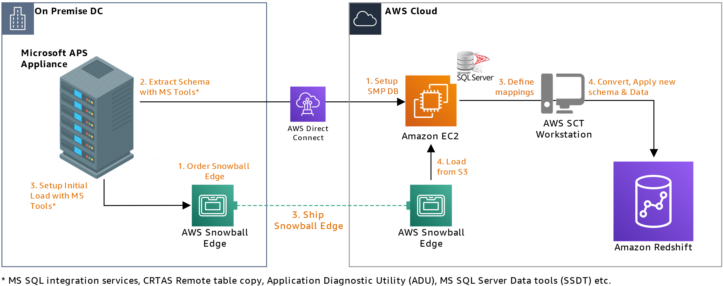
Here’s how you’ll set up the base approach (Figure 2):

  1. Set up the SMP SQL Server on Amazon EC2 and AWS SCT in your AWS account.
  2. Set up Microsoft tools, including SQL Server Data Tools (SSDT), remote table copy, and SQL Server Integration Services (SSIS).
  3. Use the Application Diagnostic Utility (ADU) and SSDT to connect and extract table lists, indexes, table definitions, view definitions, and stored procedures.
  4. Generate data description languages (DDLs) using step 3 outputs.
  5. Apply these DDLs to the SMP SQL Server on Amazon EC2.
  6. Run AWS SCT against the SMP SQL database to begin migrating schema and data to Amazon Redshift.
  7. Extract data using remote table copy from source, which copies data into the SMP SQL Server.
  8. Load this data into Amazon Redshift using AWS SCT or AWS Database Migration Service (AWS DMS).
  9. Use SSIS to load delta data from source to the SMP SQL Server on Amazon EC2.
Base approach using SMP SQL Server on Amazon EC2

Figure 2. Base approach using SMP SQL Server on Amazon EC2

Extending the base approach

The base approach overcomes server-side issues you would have during a direct migration. However, many organizations host terabytes (TB) of data. To migrate such a large dataset, you’ll need to adjust your approach.

The following sections extend the base approach. They still use the base approach to convert the schema and procedures, but the dataset is handled via separate processes.

Extension 1: AWS Snowball Edge

Note: AWS Snowball Edge is a Region-specific service. Verify that the service is available in your Region before planning your migration. See Regional Table to verify availability.

Snowball Edge lets you transfer large datasets to the cloud at faster-than-network speeds. Each Snowball Edge device can hold up to 100 TB and uses 256-bit encryption and an industry-standard Trusted Platform Module to ensure security and full chain-of-custody for your data. Furthermore, higher volumes can be transferred by clustering 5–10 devices for increased durability and storage.

Extension 1 enhances the base approach to allow you to transfer large datasets (Figure 3) while simultaneously setting up an SMP SQL Server on Amazon EC2 for delta transfers. Here’s how you’ll set it up:

  1. Once Snowball Edge is enabled in the on-premises environment, it allows data transfer via network file system (NFS) endpoints. The device can then be used with standard Microsoft tools like SSIS, remote table copy, ADU, and SSDT.
  2. While the device is being shipped back to an AWS facility, you’ll set up an SMP SQL Server database on Amazon EC2 to replicate the base approach.
  3. After your data is converted, you’ll apply a converted schema to Amazon Redshift.
  4. Once the Snowball Edge arrives at the AWS facility, data is transferred to the SMP SQL Server database.
  5. You’ll subsequently run schema conversions and initial and delta loads per the base approach.
Solution extension that uses Snowball Edge for large datasets

Figure 3. Solution extension that uses Snowball Edge for large datasets

Note: Where sequence numbers overlap in the diagram is a suggestion to possible parallel execution

Extension 1 transfers initial load and later applies delta load. This adds time to the project because of longer cutover release schedules. Additionally, you’ll need to plan for multiple separate outages, Snowball lead times, and release management timelines.

Note that not all analytics systems are classified as business-critical systems, so they can withstand a longer outage, typically 1-2 days. This gives you an opportunity to use AWS DataSync as an additional extension to complete initial and delta load in a single release window.

Extension 2: AWS DataSync

DataSync speeds up data transfer between on-premises environments and AWS. It uses a purpose-built network protocol and a parallel, multi-threaded architecture to accelerate your transfers.

Figure 4 shows the solution extension, which works as follows:

  1. Create SMP MS SQL Server on EC2 and the DDL, as shown in the base approach.
  2. Deploy DataSync agent(s) in your on-premises environment.
  3. Provision and mount an NFS volume on the source analytics platform and DataSync agent(s).
  4. Define a DataSync transfer task after the agents are registered.
  5. Extract initial load from source onto the NFS mount that will be uploaded to Amazon Simple Storage Service (Amazon S3).
  6. Load data extracts into the SMP SQL Server on Amazon EC2 instance (created using base approach).
  7. Run delta loads per base approach, or continue using solution extension for delta loads.
Solution extension that uses DataSync for large datasets

Figure 4. Solution extension that uses DataSync for large datasets

Note: where sequence numbers overlap in the diagram is a suggestion to possible parallel execution

Transfer rates for DataSync depend on the amount of data, I/O, and network bandwidth available. A single DataSync agent can fully utilize a 10 gigabit per second (Gbps) AWS Direct Connect link to copy data from on-premises to AWS. As such, depending on initial load size, transfer window calculations must be done prior to finalizing transfer windows.

Conclusion

The approach and its extensions mentioned in this blog post provide mechanisms to migrate your Microsoft APS workloads to an Amazon Redshift CDW. They enable elasticity, scalability, and agility for your workload to future proof your analytics investment.

Related information

Opportunistic Exploitation of Zoho ManageEngine and Sitecore CVEs

Post Syndicated from Caitlin Condon original https://blog.rapid7.com/2021/11/09/opportunistic-exploitation-of-zoho-manageengine-and-sitecore-cves/

Opportunistic Exploitation of Zoho ManageEngine and Sitecore CVEs

Over the weekend of November 6, 2021, Rapid7’s Incident Response (IR) and Managed Detection and Response (MDR) teams began seeing opportunistic exploitation of two unrelated CVEs:

  • CVE-2021-40539, a REST API authentication bypass in Zoho’s ManageEngine ADSelfService Plus product that Rapid7 has previously analyzed. CISA warned of attackers targeting CVE-2021-40539 in September; the vulnerability allows for unauthenticated remote code execution upon successful exploitation. As of November 8, 2021, Microsoft is also warning that a specific threat actor is targeting vulnerable ManageEngine ADSelfService Plus installations.
  • CVE-2021-42237, a deserialization vulnerability in the Sitecore Experience Platform that allows for unauthenticated remote code execution in earlier versions. The affected versions of Sitecore XP appear to be several years old and unsupported other than through extended support contracts. With that said, there seem to be a higher number of organizations with vulnerable installations than expected based on the rate of compromise Rapid7 teams have observed.

Attackers appear to be targeting vulnerabilities with attacks that drop webshells and install coin miners on vulnerable targets. The majority of the compromises Rapid7’s services teams have seen are the result of vulnerable Sitecore instances. Both CVEs are patched; ManageEngine ADSelfService Plus and Sitecore XP customers should prioritize fixes on an urgent basis, without waiting for regularly scheduled patch cycles.

Rapid7 customers

The following attacker behavior detections are available to InsightIDR and MDR customers and will alert security teams to webshells and powershell activity related to this attack:

  • Webshell – IIS Spawns CMD to Spawn PowerShell
  • Attacker Technique – PowerShell Download Cradle

InsightVM and Nexpose customers can assess their exposure to Zoho ManageEngine CVE-2021-40539 with a remote vulnerability check. Rapid7 vulnerability researchers have a full technical analysis of this vulnerability available here. Our research teams are investigating the feasibility of adding a vulnerability check for Sitecore XP CVE-2021-42237. A technical analysis of this vulnerability is available here.

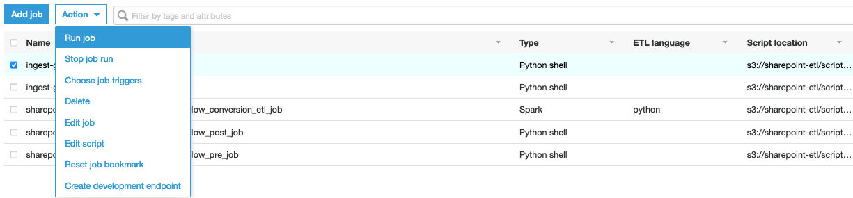
NEVER MISS A BLOG

Get the latest stories, expertise, and news about security today.

Ransomware Takeaways: Q3 2021

Post Syndicated from Jeremy Milk original https://www.backblaze.com/blog/ransomware-takeaways-q3-2021/

While the first half of 2021 saw disruptive, high-profile attacks, Q3 saw attention and intervention at the highest levels. Last quarter, cybercriminals found themselves in the sights of government and law enforcement agencies as they responded to the vulnerabilities the earlier attacks revealed. Despite these increased efforts, the ransomware threat remains, simply because the rewards continue to outweigh the risks for bad actors.

If you’re responsible for protecting company data, ransomware news is certainly on your radar. In this series of posts, we aim to keep you updated on evolving trends as we see them to help inform your IT decision-making. Here are five key takeaways from our monitoring over Q3 2021.

This post is a part of our ongoing series on ransomware. Take a look at our other posts for more information on how businesses can defend themselves against a ransomware attack, and more.

1. Ransomware Attacks Keep Coming

No surprises here. Ransomware operators continued to carry out attacks—against Howard University, Accenture, and the fashion brand Guess, to name a few. In August, the FBI’s Cyber Division and the Cybersecurity and Infrastructure Security Agency (CISA) reported an increase in attacks on holidays and weekends and alerted businesses to be more vigilant as we approach major holidays. Then, in early September, the FBI also noticed an uptick in attacks on the food and agriculture sector. The warnings proved out, and in late September, we saw a number of attacks against farming cooperatives in Iowa and Minnesota. While the attacks were smaller in scale compared to those earlier in the year, the reporting speaks to the fact that ransomware is definitely not a fad that’s on a downswing.

2. More Top-down Government Intervention

Heads of state and government agencies took action in response to the ransomware threat last quarter. In September, the U.S. Treasury Department updated an Advisory that discourages private companies from making ransomware payments, and outlines mitigating factors it would consider when determining a response to sanctions violations. The Advisory makes clear that the Treasury will expect companies to do more to proactively protect themselves, and may be less forgiving to those who pay ransoms without doing so.

Earlier in July, the TSA also issued a Security Directive that requires pipeline owners and operators to implement specific security measures against ransomware, develop recovery plans, and conduct a cybersecurity architecture review. The moves demonstrate all the more that the government doesn’t take the ransomware threat lightly, and may continue to escalate actions.

3. Increased Scrutiny on Key Players Within the Ransomware Economy

Two major ransomware syndicates, REvil and Darkside, went dark days after President Joe Biden’s July warning to Russian President Vladimir Putin to rein in ransomware operations. We now see this was but a pause. However, the rapid shuttering does suggest executive branch action can make a difference, in one country or another.

Keep in mind, though, that the ransomware operators themselves are just one part of the larger ransomware economy (detailed in the infographic at the bottom of the post). Two other players within the ransomware economy faced increased pressure this past quarter—currency exchanges and cyber insurance carriers.

  • Currency Exchanges: In addition to guidance for private businesses, the Treasury Department’s September Advisory specifically added the virtual currency exchange, SUEX, to the Specially Designated Nationals and Blocked Persons List, after it found that more than 40% of the exchange’s transactions were likely related to ransomware payments. The Advisory imposed sanctions that prohibit any U.S. individual or entity from engaging in transactions with SUEX.
  • Cyber Insurance Carriers: It makes sense the cyber insurance industry is booming—the economics of risk make it lucrative for certain providers. Interestingly, though, we’re starting to see more discussion of how cyber insurance providers and the victim-side vendors they engage with—brokers, negotiators, and currency platforms like SUEX—are complicit in perpetuating the ransomware cycle. Further, the Treasury Department’s September Advisory also included a recommendation to these victim-side vendors to implement sanctions compliance programs that account for the risk that payments may be made to sanctioned entities.

4. An Emerging Moral Compass?

In messages with Bloomberg News, the BlackMatter syndicate pointed out its rules of engagement, saying hospitals, defense, and governments are off limits. But, sectors that are off limits to some are targets for others. While some syndicates work to define a code of conduct for criminality, victims continue to suffer. According to a Ponemon survey of 597 health care organizations, ransomware attacks have a significant impact on patient care. Respondents reported longer length of stay (71%), delays in procedures and tests (70%), increase in patient transfers or facility diversions (65%), and an increase in complications from medical procedures (36%) and mortality rates (22%).

5. Karma Is a Boomerang

It’s not surprising that ransomware operators would steal from their own, but that doesn’t make it any less comical to hear low-level ransomware affiliates complaining of “lousy partner programs” hawked by ransomware gangs “you cannot trust.” ZDNet reports that the REvil group has been accused of coding a “backdoor” into their affiliate product that allows the group to barge into negotiations and take the keep all for themselves. It’s a dog-eat-dog world out there.

The Good News

This quarter, the good news is that ransomware has caught the attention of the people who can take steps to curb it. Government recommendations to strengthen ransomware protection make investing the time and effort easier to justify, especially when it comes to your cloud strategy. If there’s anything this quarter taught us, it’s that ransomware protection should be priority number one.

If you want to share this infographic on your site, copy the code below and paste into a Custom HTML block. 

<div><div><strong>The Ransomware Economy</strong></div><a href="https://www.backblaze.com/blog/ransomware-takeaways-q3-2021/"><img src="https://www.backblaze.com/blog/wp-content/uploads/2021/11/The-Ransomware-Economy-Q3-2021-scaled.jpg" border="0" alt="diagram of the players and elements involved in spreading ransomware" title="diagram of the players and elements involved in spreading ransomware" /></a></div>

The post Ransomware Takeaways: Q3 2021 appeared first on Backblaze Blog | Cloud Storage & Cloud Backup.

The collective thoughts of the interwebz