Post Syndicated from Matt Granger original https://www.youtube.com/watch?v=i-QC7vZt6mc
Alex Kim: Why I joined Cloudflare
Post Syndicated from Alex Kim original https://blog.cloudflare.com/alex-kim-why-i-joined-cloudflare/


I am excited to announce that as of November 1, I have joined Cloudflare as Country Manager of South Korea to help build a better Internet and to expand Cloudflare’s growing customer, partner, and local teams in Korea. We just opened a new entity (after making Seoul our 23rd data center, more than 10 years ago) and I am the first official employee of Cloudflare Korea LLC in Seoul, which is truly a great moment and privilege for me.
A little about me
I was born in Korea and was educated in Korea until middle school, then I decided to move to Toronto, Canada to study film making to become a movie director. I finished high school and obtained a university degree in Toronto, during which I had the opportunity to be exposed to various cultures, as well as learn and become well-versed in the English language. I think it was a great time to learn how diverse people in the world are. My dream of becoming a movie director has changed over time for many reasons, but I think it is no coincidence that I have a job where I have to produce results while collaborating and orchestrating with many people, much like a movie director.
In my career of about 18 years, I have had various experiences, including pre-sales, support, consultant, and field sales, starting with Java programmer. The lesson from this variety of experiences is that if you work with a sense of ownership all the time, you can be the best in the field, and you can get the best compliments from your customers.
I’ve worked in a small company where the whole company has been agile, and I’ve worked in large companies like SAP, Dell, Autodesk, and Akamai, working with many teams. New technology and the best technology are important, but I also learned that the most important thing is the environment where people can work together and have fun, because people make the results after all.
Besides work, I love music. I didn’t become a movie director, which was my childhood dream, but I relieve my stress by playing the piano and composing songs. In the past, I made a rock song for one of the companies I worked for, and when an opportunity presented itself, we had a program where all the employees jumped in and sang my composition together. Unfortunately, I have not had enough time to make a lot of songs now, but if I have a chance, I would love to make a Cloudflare song and hope I can sing it together with my new colleagues.
Why Cloudflare
Korea has one of the highest smartphone and Internet penetration rates in the world. Korea is also one of the countries with the fastest Internet speeds in the world. On the other hand, the pace of cloud transformation, that is making such a big difference to so many companies, is still lagging behind. The reason is that there are many government regulations on public enterprises and finance industries. Fortunately, as the government has recently moved to ease many regulations, the pace of cloud transformation is expected to accelerate in the future.
As cloud transitions accelerate, enterprises need to pay attention to security, and few companies will be able to deploy security as easily and securely in a cloud environment as Cloudflare.
Korea is a country where the economy grows only when it exports a lot. Many startups and chaebol (conglomerate) companies often grow future-oriented industries such as metaverse in Korea first and then expand their business abroad. For customers leading this global industry, Cloudflare will act like a safe highway in an Internet environment. I’ve come to Cloudflare to be part of this meaningful work.
In addition, Cloudflare Korea has just been launched. Even though we’ve had a presence here through our data center for the last 10 years, there are still many companies that we still need to build relationships with. I want to spread the value of Cloudflare to the Korean market quickly and become a Supercloud evangelist. I would also like to help Korean customers — organizations and businesses across multiple industries — achieve great success and ensure they have the right technology and Internet infrastructure. In the next few years, I will work hard to establish Cloudflare as the most trusted cloud security company in Korea, as well as contribute to expanding the business and creating jobs in the country.
The vision for the future…
As the first Country Manager of Cloudflare Korea, I am very excited to work for a company with unlimited growth potential. As the global economy slows down, customers will gravitate towards products and solutions that are more valuable and price competitive. I’m looking forward to meeting and working with more customers that will benefit from all that Cloudflare has to offer.
One of the biggest reasons I chose Cloudflare is that Cloudflare has big dreams and visions. In particular, I think the emergence of R2 will provide an extremely cost-effective solution to enterprises’ egress cost concerns, especially in economically challenging times.
In addition, Cloudflare is investing heavily to become the number one Zero Trust player. The VPN market is huge, and it has a lot of challenges (including user experience, speed, and security), and Zero Trust is still in its infancy but already showing its true potential. Cloudflare, which understands and invests in these huge markets, knows where to go in the marketplace.
Finally, the Supercloud is also an area that only Cloudflare can realize. Cloud security and Zero Trust are indispensable areas of the future, and I am very happy to join this futuristic company.
[$] LWN.net Weekly Edition for December 8, 2022
Post Syndicated from original https://lwn.net/Articles/916497/
The LWN.net Weekly Edition for December 8, 2022 is available.
Tor Browser 12.0 released
Post Syndicated from original https://lwn.net/Articles/917282/
Version
12.0 of the Tor browser has been released. Changes include
multi-locale support, Apple silicon support, HTTPS-only behavior by default
on Android and more.
How dynamic data masking support in Amazon Redshift helps achieve data privacy and compliance
Post Syndicated from Rohit Vashishtha original https://aws.amazon.com/blogs/big-data/how-dynamic-data-masking-support-in-amazon-redshift-helps-achieve-data-privacy-and-compliance/
Amazon Redshift is a fully managed, petabyte-scale, massively parallel data warehouse that offers simple operations and high performance. It makes it fast, simple, and cost-effective to analyze all your data using standard SQL and your existing business intelligence (BI) tools. Today, Amazon Redshift is the most widely used cloud data warehouse.
Dynamic data masking (DDM) support (preview) in Amazon Redshift enables you to simplify the process of protecting sensitive data in your Amazon Redshift data warehouse. You can now use DDM to protect data based on your job role or permission rights and level of data sensitivity through a SQL interface. DDM support (preview) in Amazon Redshift enables you to hide, obfuscate, or pseudonymize column values within the tables in your data warehouse without incurring additional storage costs. It is configurable to allow you to define consistent, format-preserving, and irreversible masked data values.
DDM support (preview) in Amazon Redshift provides a native feature to support your need to mask data for regulatory or compliance requirements, or to increase internal privacy standards. Compared to static data masking where underlying data at rest gets permanently replaced or redacted, DDM support (preview) in Amazon Redshift enables you to temporarily manipulate the display of sensitive data in transit at query time based on user privilege, leaving the original data at rest intact. You control access to data through masking policies that apply custom obfuscation rules to a given user or role. That way, you can respond to changing privacy requirements without altering the underlying data or editing SQL queries.
With DDM support (preview) in Amazon Redshift, you can do the following:
- Define masking policies that apply custom obfuscation policies (for example, masking policies to handle credit card, PII entries, HIPAA or GDPR needs, and more)
- Transform the data at query time to apply masking policies
- Attach masking policies to roles or users
- Attach multiple masking policies with varying levels of obfuscation to the same column in a table and assign them to different roles with priorities to avoid conflicts
- Implement cell-level masking by using conditional columns when creating your masking policy
- Use masking policies to partially or completely redact data, or hash it by using user-defined functions (UDFs)
Here’s what our customers have to say on DDM support(private beta) in Amazon Redshift:
“Baffle delivers data-centric protection for enterprises via a data security platform that is transparent to applications and unique to data security. Our mission is to seamlessly weave data security into every data pipeline. Previously, to apply data masking to an Amazon Redshift data source, we had to stage the data in an Amazon S3 bucket. Now, by utilizing the Amazon Redshift Dynamic Data Masking capability, our customers can protect sensitive data throughout the analytics pipeline, from secure ingestion to responsible consumption reducing the risk of breaches.”
-Ameesh Divatia, CEO & co-founder of Baffle
“EnergyAustralia is a leading Australian energy retailer and generator, with a mission to lead the clean energy transition for customers in a way that is reliable, affordable and sustainable for all. We enable all corners of our business with Data & Analytics capabilities that are used to optimize business processes and enhance our customers’ experience. Keeping our customers’ data safe is a top priority across our teams. In the past, this involved multiple layers of custom built security policies that could make it cumbersome for analysts to find the data they require. The new AWS dynamic data masking feature will significantly simplify our security processes so we continue to keep customer data safe, while also reducing the administrative overhead.”
-William Robson, Data Solutions Design Lead, EnergyAustralia
Use case
For our use case, a retail company wants to control how they show credit card numbers to users based on their privilege. They also don’t want to duplicate the data for this purpose. They have the following requirements:
- Users from Customer Service should be able to view the first six digits and the last four digits of the credit card for customer verification
- Users from Fraud Prevention should be able to view the raw credit card number only if it’s flagged as fraud
- Users from Auditing should be able to view the raw credit card number
- All other users should not be able to view the credit card number
Solution overview
The solution encompasses creating masking policies with varying masking rules and attaching one or more to the same role and table with an assigned priority to remove potential conflicts. These policies may pseudonymize results or selectively nullify results to comply with retailers’ security requirements. We refer to multiple masking policies being attached to a table as a multi-modal masking policy. A multi-modal masking policy consists of three parts:
- A data masking policy that defines the data obfuscation rules
- Roles with different access levels depending on the business case
- The ability to attach multiple masking policies on a user or role and table combination with priority for conflict resolution
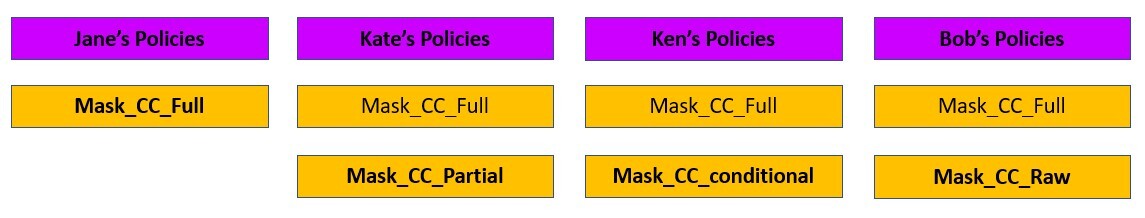
The following diagram illustrates how DDM support (preview) in Amazon Redshift policies works with roles and users for our retail use case.
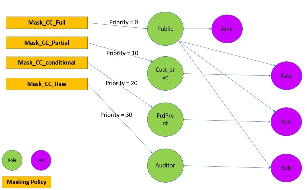
For a user with multiple roles, the masking policy with the highest attachment priority is used. For example, in the following example, Ken is part of the Public and FrdPrvnt role. Because the FrdPrvnt role has a higher attachment priority, card_number_conditional_mask will be applied.
Prerequisites
To implement this solution, you need to complete the following prerequisites:
- Have an AWS account.
- Have an Amazon Redshift cluster provisioned with DDM support (preview) or a serverless workgroup with DDM support (preview).
- Navigate to the provisioned or serverless Amazon Redshift console and choose Create preview cluster.

- In the create cluster wizard, choose the preview track.

- Navigate to the provisioned or serverless Amazon Redshift console and choose Create preview cluster.
- Have Superuser privilege, or the
sys:secadminrole on the Amazon Redshift data warehouse created in step 2.


Preparing the data
To set up our use case, complete the following steps:
- On the Amazon Redshift console, choose Query editor v2 in Explorer.
If you’re familiar with SQL Notebooks, you can download the Jupyter notebook for the demonstration, and import it to quickly get started. - Create the table and populate contents.
- Create users.
Implement the solution
To satisfy the security requirements, we need to make sure that each user sees the same data in different ways based on their granted privileges. To do that, we use user roles combined with masking policies as follows:
- Create user roles and grant different users to different roles:
- Create masking policies:
- Attach the masking policies on the table or column to the user or role:
Test the solution
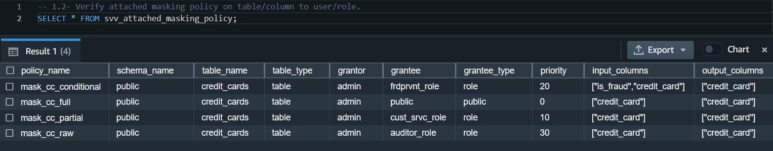
Let’s confirm that the masking policies are created and attached.
- Check that the masking policies are created with the following code:

- Check that the masking policies are attached:

Now we can test that different users can see the same data masked differently based on their roles.
- Test that the Customer Service agents can only view the first six digits and the last four digits of the credit card number:

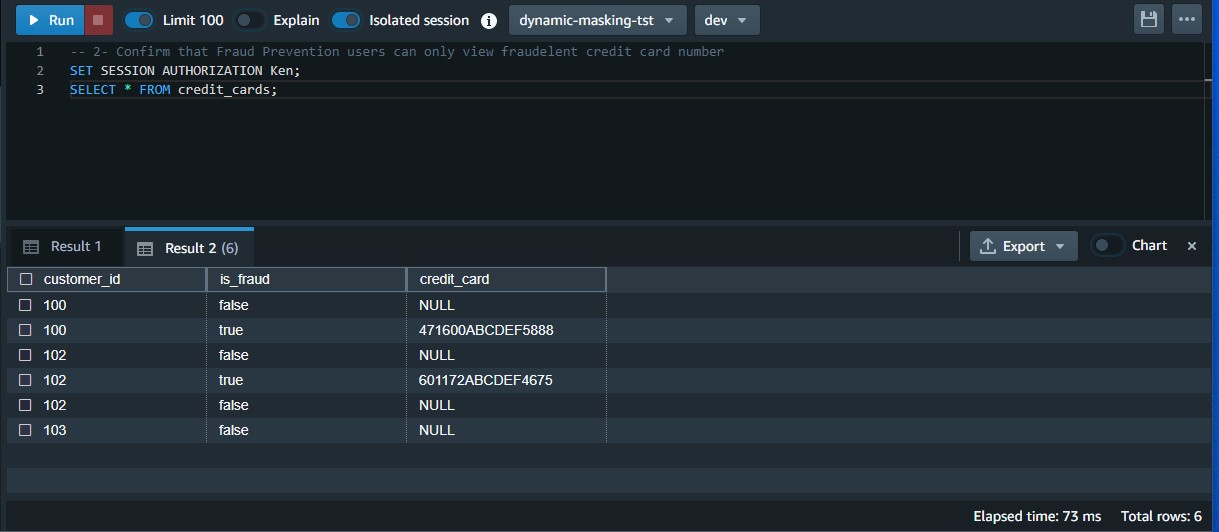
- Test that the Fraud Prevention users can only view the raw credit card number when it’s flagged as fraud:

- Test that Auditor users can view the raw credit card number:

- Test that general users can’t view any digits of the credit card number:


Modify the masking policy
To modify an existing masking policy, you must detach it from the role first and then drop and recreate it.
In our use case, the business changed direction and decided that Customer Service agents should only be allowed to view the last four digits of the credit card number.
- Detach and drop the policy:
- Recreate the policy and reattach the policy on the table or column to the intended user or role.Note that this time we created a scalar Python UDF. It’s possible to create a SQL, Python, and Lambda UDF based on your use case.
- Test that Customer Service agents can only view the last four digits of the credit card number:


Clean up
When you’re done with the solution, clean up your resources:
- Detach the masking policies from the table:
- Drop the masking policies:
- Revoke and drop each user and role:
- Drop the function and table:
Considerations and best practices
Consider the following:
- Always create a default policy attached to the public user. If you create a new user, they will always have a minimum policy attached. It will enforce the intended security posture.
- Remember that DDM policies in Amazon Redshift always follow invoker permissions convention, not definer (for more information, refer to Security and privileges for stored procedures ). That being said, the masking policies are applicable based on the user or role running it.
- For best performance, create the masking functions using a scalar SQL UDF, if possible. The performance of scalar UDFs typically goes by the order of SQL to Python to Lambda, in that order. Generally, SQL UDF outperforms Python UDFs and the latter outperforms scalar Lambda UDFs.
- DDM policies in Amazon Redshift are applied ahead of any predicate or join operations. For example, if you’re running a join on a masked column (per your access policy) to an unmasked column, the join will lead to a mismatch. That’s an expected behavior.
- Always detach a masking policy from all users or roles before dropping it.
- As of this writing, the solution has the following limitations:
- You can apply a mask policy on tables and columns and attach it to a user or role, but groups are not supported.
- You can’t create a mask policy on views, materialized views, and external tables.
- The DDM support (preview) in Amazon Redshift is available in following regions: US East (Ohio), US East (N. Virginia), US West (Oregon), Asia Pacific (Tokyo), Europe (Ireland), and Europe (Stockholm).
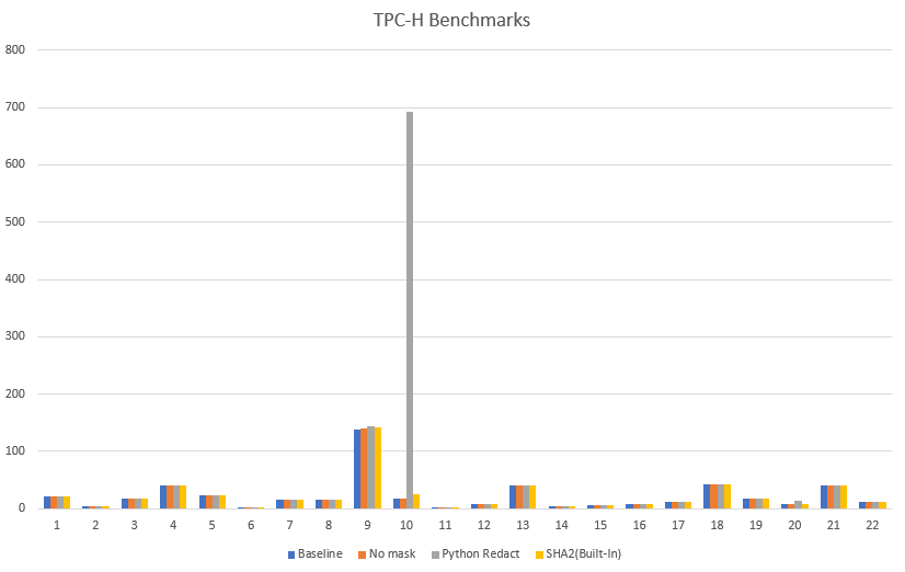
Performance benchmarks
Based on various tests performed on TPC-H datasets, we’ve found built-in functions to be more performant as compared to functions created externally using scalar Python or Lambda UDFs.
Expand the solution
You can take this solution further and set up a masking policy that restricts SSN and email address access as follows:
- Customer Service agents accessing pre-built dashboards may only view the last four digits of SSNs and complete email addresses for correspondence
- Analysts cannot view SSNs or email addresses
- Auditing services may access raw values for SSNs as well as email addresses
For more information, refer to Use DDM support (preview) in Amazon Redshift for E-mail & SSN Masking.
Conclusion
In this post, we discussed how to use DDM support (preview) in Amazon Redshift to define configuration-driven, consistent, format-preserving, and irreversible masked data values. With DDM support (preview) in Amazon Redshift, you can control your data masking approach using familiar SQL language. You can take advantage of the Amazon Redshift role-based access control capability to implement different levels of data masking. You can create a masking policy to identify which column needs to be masked, and you have the flexibility of choosing how to show the masked data. For example, you can completely hide all the information of the data, replace partial real values with wildcard characters, or define your own way to mask the data using SQL expressions, Python, or Lambda UDFs. Additionally, you can apply a conditional masking based on other columns, which selectively protects the column data in a table based on the values in one or more columns.
We encourage you to create your own user defined functions for various use-cases and accomplish desired security posture using dynamic data masking support in Amazon Redshift.
About the Authors
 Rohit Vashishtha is a Senior Analytics Specialist Solutions Architect at AWS based in Dallas, TX. He has more than 16 years of experience architecting, building, leading, and maintaining big data platforms. Rohit helps customers modernize their analytic workloads using the breadth of AWS services and ensures that customers get the best price/performance with the utmost security and data governance.
 Ahmed Shehata is a Senior Analytics Specialist Solutions Architect at AWS based on Toronto. He has more than two decades of experience helping customers modernize their data platforms. Ahmed is passionate about helping customers build efficient, performant, and scalable analytic solutions.
 Variyam Ramesh is a Senior Analytics Specialist Solutions Architect at AWS based in Charlotte, NC. He is an accomplished technology leader helping customers conceptualize, develop, and deliver innovative analytic solutions.
 Yanzhu Ji is a Product Manager in the Amazon Redshift team. She has experience in product vision and strategy in industry-leading data products and platforms. She has outstanding skill in building substantial software products using web development, system design, database, and distributed programming techniques. In her personal life, Yanzhu likes painting, photography, and playing tennis.
 James Moore is a Technical Lead at Amazon Redshift focused on SQL features and security. His work over the last 10 years has spanned distributed systems, machine learning, and databases. He is passionate about building scalable software that enables customers to solve real-world problems.
Simplify data ingestion from Amazon S3 to Amazon Redshift using auto-copy
Post Syndicated from Jason Pedreza original https://aws.amazon.com/blogs/big-data/simplify-data-ingestion-from-amazon-s3-to-amazon-redshift-using-auto-copy/
Amazon Redshift is a fast, scalable, secure, and fully managed cloud data warehouse that makes it simple and cost-effective to analyze your data using standard SQL and your existing business intelligence (BI) tools. Tens of thousands of customers today rely on Amazon Redshift to analyze exabytes of data and run complex analytical queries, making it the most widely used cloud data warehouse.
Data ingestion is the process of getting data to Amazon Redshift. You can leverage one of the many zero-ETL integration methods to make data available in Amazon Redshift directly. However, if your data is in your Amazon S3 bucket, then you can simply load data from Amazon Simple Storage Service (Amazon S3) to Amazon Redshift using the COPY command. A COPY command is the most efficient way to load a table from S3 because it uses the Amazon Redshift’s massively parallel processing (MPP) architecture to read and load data in parallel.
Amazon Redshift launched auto-copy support to simplify data loading from Amazon S3 into Amazon Redshift. You can now setup continuous file ingestion rules to track your Amazon S3 paths and automatically load new files without the need for additional tools or custom solutions. This also enables end users to have the latest data available in Amazon Redshift shortly after the source data is available.
This post shows you how to build automatic file ingestion pipelines in Amazon Redshift when source files are located on Amazon S3 by using a simple SQL command. In addition, we show you how to enable auto-copy using auto-copy jobs, how to monitor jobs, considerations, and best practices.
Overview of the auto-copy feature in Amazon Redshift
The auto-copy feature in Amazon Redshift leverages the S3 event integration to automatically load data into Amazon Redshift and simplifies automatic data loading from Amazon S3 with a simple SQL command. You can enable Amazon Redshift auto-copy by creating auto-copy jobs. A auto-copy job is a database object that stores, automates, and reuses the COPY statement for newly created files that land in the S3 folder.
The following diagram illustrates this process.

S3 event integration and auto-copy jobs have the following benefits:
- Users can now load data from Amazon S3 automatically without having to build a pipeline or using an external framework
- auto-copy jobs offer automatic and incremental data ingestion from an Amazon S3 location without the need to implement a custom solution
- This functionality comes at no additional cost
- Existing COPY statements can be converted into auto-copy jobs by appending the
JOB CREATE <job_name>parameter - It keeps track of loaded files and minimizes data duplication.
- It can be quickly set up using a simple SQL statement using your choice of JDBC/ODBC clients.
- It has automatic error handling of bad quality data files.
- It has a mechanism to load-once for each file. This means that there is no need to generate explicit manifest files.
Prerequisites
To get started with auto-copy, you need the following prerequisites:
- An AWS account
- An encrypted Amazon Redshift provisioned cluster or Amazon redshift serverless workgroup
- An Amazon S3 bucket
- Add following to the Amazon S3 bucket policy
Set up Amazon S3 event Integration
An Amazon S3 event integration facilitates seamless and automated data ingestion from S3 buckets into an Amazon Redshift data warehouse, streamlining the process of transferring and storing data for analytical purposes
- Sign in to the AWS Management Console and Navigate to Amazon Redshift home page. Under Integrations section choose S3 event integrations

- Choose Create S3 event integration

- Enter Integration name and Description, choose Next

- Choose Browse S3 buckets, a dialog box pops up, select the Amazon S3 bucket and choose Continue

- Amazon S3 bucket is selected. Choose Next

- Choose Browse Redshift data warehouse

- Choose the Amazon Redshift data warehouse and choose Continue

- Then Amazon Redshift resource policy needs access to S3 event integration. In case of Resource policy error, check Fix it for me and choose Next

- Add Tags as required and choose Next

- Review changes and choose Create S3 event integration


- An S3 event integration is created. Wait until the status of S3 event integration is Active


Set up auto-copy jobs
In this section, we demonstrate how to automate data loading of files from Amazon S3 into Amazon Redshift. With the existing COPY syntax, we add the JOB CREATE parameter to perform a one-time setup for automatic file ingestion. See the following code:
Auto ingestion is enabled by default on auto-copy jobs. Files already present at the S3 location will not be visible to the auto-copy job. Only files added after JOB creation are tracked by Amazon Redshift.
Automate ingestion from a single data source
With a auto-copy job, you can automate ingestion from a single data source by creating one job and specifying the path to the S3 objects that contain the data. The S3 object path can reference a set of folders that have the same key prefix.
In this example, we have multiple files that are being loaded on a daily basis containing the sales transactions across all the stores in the US. For this we can create a store_sales folder in the bucket.

The following code creates the store_sales table:
Next, we create the auto-copy job to automatically load the gzip-compressed files into the store_sales table:
Each day’s sales transactions are loaded to their own folder in Amazon S3.

Now upload the files for transaction sold on 2002-12-31. Each folder contains multiple gzip-compressed files.

Since the auto-copy job is already created, it automatically loads the gzip-compressed files located in the S3 object path specified in the COPY command to the store_sales table.
Let’s run a query to get the daily total of sales transactions across all the stores in the US:
The output shown comes from the transactions sold on 2002-12-31.

The following day, incremental sales transactions data are loaded to a new folder in the same S3 object path.

As new files arrive to the same S3 object path, the auto-copy job automatically loads the unprocessed files to the store_sales table in an incremental fashion.
All new sales transactions for 2003-01-01 are automatically ingested, which can be verified by running the following query:

Automate ingestion from multiple data sources
We can also load an Amazon Redshift table from multiple data sources. When using a pub/sub pattern where multiple S3 buckets populate data to an Amazon Redshift table, you have to maintain multiple data pipelines for each source/target combination. With new parameters in the COPY command, this can be automated to handle data loads efficiently.
In the following example, the Customer_1 folder has Green Cab Company sales data, and the Customer_2 folder has Red Cab Company sales data. We can use the COPY command with the JOB parameter to automate this ingestion process.

The following screenshot shows sample data stored in files. Each folder has similar data but for different customers.

The target for these files in this example is the Amazon Redshift table cab_sales_data.
Define the target table cab_sales_data:
You can define two auto-copy jobs as shown in the following code to handle and monitor the ingestion of sales data belonging to different customers, in our case Customer_1 and Customer_2. These jobs monitor the Customer_1 and Customer_2 folders and load new files that are added here.
After setting up the two jobs, we can upload the relevant files into their respective folders. This will make sure that the data is loaded efficiently as soon as the files arrive. Each customer is assigned its own vendorid, as shown in the following output:

Manually run a auto-copy job
There might be scenarios wherein the auto-copy job needs to be paused, meaning it needs to stop looking for new files, for example, to fix a corrupted data pipeline at the data source.
In that case, either use the auto-copy job ALTER command to set AUTO to OFF or create a new auto-copy job with AUTO OFF. Once this is set, auto copy will no longer look for new files.
If necessary, users can manually invoke auto-copy job which will do the work and ingest if new files are found.
auto-copy job RUN <auto-copy job Name>
You can disable “AUTO ON” in the existing auto-copy job using the following command:
auto-copy job ALTER <auto-copy job Name> AUTO OFF
The following table compares the syntax and data duplication between a regular copy statement and the new auto-copy job
| . | Copy | Auto-copy job |
| Syntax | COPY <table-name> |
COPY <table-name> |
| Data Duplication | If it is run multiple times against the same S3 folder, it will load the data again, resulting in data duplication. | It will not load the same file twice, preventing data duplication. |
Error handling and monitoring for auto-copy jobs
auto-copy jobs continuously monitor the S3 folder specified during job creation and perform ingestion whenever new files are created. New files created under the S3 folder are loaded exactly once to avoid data duplication.
By default, if there are data or format issues with the specific files, the auto-copy job will fail to ingest the files with a load error and log details to the system tables. The auto-copy job will remain AUTO ON with new data files and will continue to ignore previously failed files.
Amazon Redshift provides the following system tables for users to monitor or troubleshoot auto-copy jobs as needed:
- List auto-copy jobs – Use SYS_COPY_JOB to list the auto-copy jobs stored in the database:

- Get a summary of a auto-copy job – Use the SYS_LOAD_HISTORY view to get the aggregate metrics of a auto-copy job operation by specifying the
copy_job_id. It shows the aggregate metrics of the files that have been processed by a auto-copy job.

- Get details of a auto-copy job – Use STL_LOAD_COMMITS to get the status and details of each file that was processed by a auto-copy job:
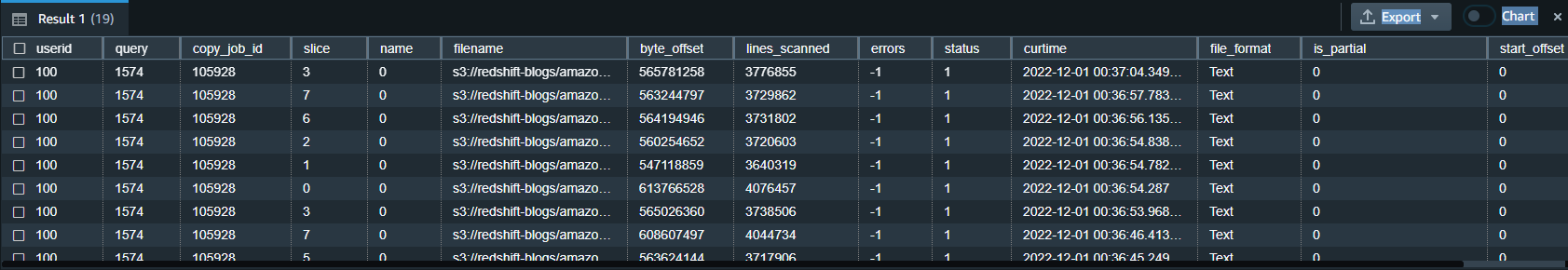
- Get exception details of a auto-copy job – Use STL_LOAD_ERRORS to get the details of files that failed to ingest from a auto-copy job:

Auto-copy job best practices
In an auto-copy job, when a new file is detected and ingested (automatically or manually), Amazon Redshift stores the file name and doesn’t run this specific job when a new file is created with the same file name.
The following are the recommended best practices when working with files using the auto-copy job:
- Use unique file names for each file in a auto-copy job (for example,
2022-10-15-batch-1.csv). However, you can use the same file name as long as it’s from different auto-copy jobs:- job_customerA_sales –
s3://redshift-blogs/sales/customerA/2022-10-15-sales.csv - job_customerB_sales –
s3://redshift-blogs/sales/customerB/2022-10-15-sales.csv
- job_customerA_sales –
- Do not update file contents. Do not overwrite existing files. Changes in existing files will not be reflected to the target table. The auto-copy job doesn’t pick up updated or overwritten files, so make sure they’re renamed as new file names for the auto-copy job to pick up.
- Run regular COPY statements (not a job) if you need to ingest a file that was already processed by your auto-copy job. (COPY statement without a JOB CREATE syntax doesn’t track loaded files.) For example, this is helpful in scenarios where you don’t have control of the file name and the initial file received failed. The following figure shows a typical workflow in this case.

- Delete and recreate your auto-copy job if you want to reset file tracking history and start over. You can drop auto-copy job using following command.
auto-copy job considerations
Here are the main things to consider when using auto-copy:
- Existing files in Amazon S3 prefix are not loaded, use Copy command to catch up historical data
- The following features are unsupported:
For additional details on other considerations for auto-copy, refer to the AWS documentation.
Customer feedback
GE Aerospace is a global provider of jet engines, components, and systems for commercial and military aircraft. The company has been designing, developing, and manufacturing jet engines since World War I.
“GE Aerospace uses AWS analytics and Amazon Redshift to enable critical business insights that drive important business decisions. With the support for auto-copy from Amazon S3, we can build simpler data pipelines to move data from Amazon S3 to Amazon Redshift. This accelerates our data product teams’ ability to access data and deliver insights to end users. We spend more time adding value through data and less time on integrations.”
– Alcuin Weidus Sr Principal Data Architect at GE Aerospace
Conclusion
This post demonstrated how to automate data ingestion from Amazon S3 to Amazon Redshift using the auto-copy feature. This new functionality helps make Amazon Redshift data ingestion easier than ever, and will allow SQL users to get access to the most recent data using a simple SQL command.
Users can begin ingesting data to Redshift from Amazon S3 with simple SQL commands and gain access to the most up-to-date data without the need for third-party tools or custom implementation.
About the authors
 Tahir Aziz is an Analytics Solution Architect at AWS. He has worked with building data warehouses and big data solutions for over 15+ years. He loves to help customers design end-to-end analytics solutions on AWS. Outside of work, he enjoys traveling and cooking.
 Omama Khurshid is an Acceleration Lab Solutions Architect at Amazon Web Services. She focuses on helping customers across various industries build reliable, scalable, and efficient solutions. Outside of work, she enjoys spending time with her family, watching movies, listening to music, and learning new technologies.
 Raza Hafeez is a Senior Product Manager at Amazon Redshift. He has over 13 years of professional experience building and optimizing enterprise data warehouses and is passionate about enabling customers to realize the power of their data. He specializes in migrating enterprise data warehouses to AWS Modern Data Architecture.
 Jason Pedreza is an Analytics Specialist Solutions Architect at AWS with data warehousing experience handling petabytes of data. Prior to AWS, he built data warehouse solutions at Amazon.com. He specializes in Amazon Redshift and helps customers build scalable analytic solutions.
 Nita Shah is an Analytics Specialist Solutions Architect at AWS based out of New York. She has been building data warehouse solutions for over 20 years and specializes in Amazon Redshift. She is focused on helping customers design and build enterprise-scale well-architected analytics and decision support platforms.
 Eren Baydemir, a Technical Product Manager at AWS, has 15 years of experience in building customer-facing products and is currently focusing on data lake and file ingestion topics in the Amazon Redshift team. He was the CEO and co-founder of DataRow, which was acquired by Amazon in 2020.
 Eesha Kumar is an Analytics Solutions Architect with AWS. He works with customers to realize the business value of data by helping them build solutions using the AWS platform and tools.
 Satish Sathiya is a Senior Product Engineer at Amazon Redshift. He is an avid big data enthusiast who collaborates with customers around the globe to achieve success and meet their data warehousing and data lake architecture needs.
 Hangjian Yuan is a Software Development Engineer at Amazon Redshift. He’s passionate about analytical databases and focuses on delivering cutting-edge streaming experiences for customers.
About Anomalous Data Transfer detection in InsightIDR
Post Syndicated from Dina Durutlic original https://blog.rapid7.com/2022/12/07/about-anomalous-data-transfer-detection-in-insightidr/

By Shivangi Pandey
Shivangi is a Senior Product Manager for D&R at Rapid7.
Data exfiltration is an unauthorized movement or transfer of data occurring on an organization’s network. This can occur when a malicious actor gains access to a corporation’s network with the intention of stealing or leaking data.
Data exfiltration can also be carried out by inside actors moving data outside of the network accidentally, by uploading corporate files to their personal cloud – or deliberately to leak information that harms the organization.
Identifying this cyber risk is integral to securing your organization’s network.
Of course, attackers use multiple methods
Some use phishing scams to trick users into inputting personal login information into spoofed domains so that they can use the appropriate credentials to infiltrate the network. Once on to the network, the malicious actor can send the files they were searching for outside of their network using remote desktop, SSH, etc.
Another method? Ignoring security controls of a network. For example, employees may download unauthorized software for ease of use, but unintentionally allow a third party to gain access to sensitive information that was not meant to leave the network. People may use personal accounts and devices for work related tasks just because it’s easy. A malicious inside actor can also circumvent security controls to leak information outside of the network.
With many organizations moving to a hybrid model of work, it’s more important than ever to prevent data exfiltration, intended or unintended. This can be done by educating your employees of appropriate conduct when it comes to data usage and data sharing within and outside of your network. Education about common attack vectors attackers may use to steal their credentials will also help your employees keep your network secure. Additionally, education around what devices can access your network will make it easier to monitor whether a data breach is about to occur. Finally, assigning certain privileges based on employee functions will help.
Being able to detect data exfiltration is incredibly important for an organization’s environment and essential to your organization’s security posture. One of our new detections, Anomalous Data Transfer, provides you with the visibility into possible occurrences of data exfiltration within your network.
Rapid7s approach for detecting Anomalous Data Transfers
Anomalous Data Transfer is an InsightIDR detection which utilizes network flow data, produced by the Insight Network Sensor, to identify and mark unusual transfers of data and behavior. The detection identifies anomalously large transfers of data sent by assets out of a network, and outputs data exfiltration alerts
The model dynamically derives a baseline for each asset based on its active periods over 30 days, and each hour, will output network activity that is anomalously high as compared to that baseline as a candidate for further investigation. This process effectively acts as a filter, reducing millions of network connections into a few candidate alerts to bring to the attention of a security analyst.
Further contextual information is included in each candidate alert to help a security team make informed decisions about how to investigate the possible occurrence of data exfiltration.
The user has the ability to tune exceptions for which anomalous data transfer alerts are shown by going into Managed Detections. The user can tune exception rules for Anomalous Data Transfer with the following attributes: Organization, Certificate, and Source IP/Subnet. This allows for the analysts to focus on alerts that are well tailored to their organization’s environment.
CVE-2022-4261: Rapid7 Nexpose Update Validation Issue (FIXED)
Post Syndicated from Tod Beardsley original https://blog.rapid7.com/2022/12/07/cve-2022-4261-rapid7-nexpose-update-validation-issue-fixed/

On November 14, 2022, Rapid7’s product engineering team discovered that the mechanism used to validate the source of an update file was unreliable. This failure involving the internal cryptographic validation of received updates was designated as CVE-2022-4261, and is an instance of CWE-494. Rapid7’s estimate of the CVSSv3.1 base rating for this vulnerability for most environments is 4.4 (Medium). This issue is resolved in the regular December 7, 2022 release.
Product Description
Rapid7 Nexpose is an on-premise vulnerability scanner, used by many enterprises around the world to assess and manage the vulnerability exposures present in their networks. You can read more about Nexpose at our website.
Note that CVE-2022-4261 only affects the on-premise Nexpose product, and does not affect InsightVM.
Credit
This issue was discovered by Rapid7 Principal Software Engineer Emmett Kelly and validated by the Rapid7 Nexpose product team. It is being disclosed in accordance with Rapid7’s vulnerability disclosure policy.
Exploitation
Exploitation of this issue is complex, and requires an attacker already in a privileged position in the network. By understanding these complications, we believe our customers will be better able to make appropriate judgements on the risk of delaying this update, perhaps due to established change control procedures.
In order to exploit CVE-2022-4261, an attacker would first need to be in a position to provide a malicious update to Nexpose, either through a privileged position on the network, on the local computer that runs Nexpose (with sufficient privileges to initiate an update), or by convincing a Nexpose administrator to apply a maliciously-crafted update through social engineering. Once applied, the update could introduce new functionality to Nexpose that would benefit the attacker.
Impact
Given the requirement of a privileged position on the network or local machine, exploiting CVE-2022-4261, in most circumstances, is academic. Such an adversary is likely to already have many other (and often easier) choices when it comes to leveraging this position to cause trouble on the target network. In the case of a local machine compromise (which is the most likely attack scenario), the attacker could use this position to instead create a fairly permanent ingress avenue to the internal network and exercise the usual lateral movement options documented as ATT&CK technique T1557.
Remediation
Disabling automatic updates completely removes the risk of exploitation of CVE-2022-4261. That said, most Nexpose administrators already employ Nexpose’s automated updates, and should apply updates either on their already established automated schedules or as soon as it’s convenient to do so.
Nexpose administrators that are especially concerned that they will be targeted during their next update, or who believe they have already been compromised by persistent attackers, should disable automatic updates and use the documented Managing Updates without an Internet Connection procedure to fix this issue, after manually validating the authenticity of the update package.
Fixing an update system with an update is always fairly complex, given the chicken-and-egg nature of the problem being addressed, as well as the risks involved in using an update system to fix an update system. So, it is out of an abundance of caution that we are publishing this advisory today to ensure that customers who rely on automatic updates are made plainly aware of this issue and can plan accordingly.
Disclosure Timeline
- Mon, Nov 14, 2022: Issue discovered by Emett Kelly, and validated by the Nexpose product team.
- Thu, Dec 1, 2022: CVE-2022-4261 reserved by Rapid7.
- Wed, Dec 7, 2022 : This disclosure and update 6.6.172 released.
How to secure your SaaS tenant data in DynamoDB with ABAC and client-side encryption
Post Syndicated from Jani Muuriaisniemi original https://aws.amazon.com/blogs/security/how-to-secure-your-saas-tenant-data-in-dynamodb-with-abac-and-client-side-encryption/
If you’re a SaaS vendor, you may need to store and process personal and sensitive data for large numbers of customers across different geographies. When processing sensitive data at scale, you have an increased responsibility to secure this data end-to-end. Client-side encryption of data, such as your customers’ contact information, provides an additional mechanism that can help you protect your customers and earn their trust.
In this blog post, we show how to implement client-side encryption of your SaaS application’s tenant data in Amazon DynamoDB with the Amazon DynamoDB Encryption Client. This is accomplished by leveraging AWS Identity and Access Management (IAM) together with AWS Key Management Service (AWS KMS) for a more secure and cost-effective isolation of the client-side encrypted data in DynamoDB, both at run-time and at rest.
Encrypting data in Amazon DynamoDB
Amazon DynamoDB supports data encryption at rest using encryption keys stored in AWS KMS. This functionality helps reduce operational burden and complexity involved in protecting sensitive data. In this post, you’ll learn about the benefits of adding client-side encryption to achieve end-to-end encryption in transit and at rest for your data, from its source to storage in DynamoDB. Client-side encryption helps ensure that your plaintext data isn’t available to any third party, including AWS.
You can use the Amazon DynamoDB Encryption Client to implement client-side encryption with DynamoDB. In the solution in this post, client-side encryption refers to the cryptographic operations that are performed on the application-side in the application’s Lambda function, before the data is sent to or retrieved from DynamoDB. The solution in this post uses the DynamoDB Encryption Client with the Direct KMS Materials Provider so that your data is encrypted by using AWS KMS. However, the underlying concept of the solution is not limited to the use of the DynamoDB Encryption Client, you can apply it to any client-side use of AWS KMS, for example using the AWS Encryption SDK.
For detailed information about using the DynamoDB Encryption Client, see the blog post How to encrypt and sign DynamoDB data in your application. This is a great place to start if you are not yet familiar with DynamoDB Encryption Client. If you are unsure about whether you should use client-side encryption, see Client-side and server-side encryption in the Amazon DynamoDB Encryption Client Developer Guide to help you with the decision.
AWS KMS encryption context
AWS KMS gives you the ability to add an additional layer of authentication for your AWS KMS API decrypt operations by using encryption context. The encryption context is one or more key-value pairs of additional data that you want associated with AWS KMS protected information.
Encryption context helps you defend against the risks of ciphertexts being tampered with, modified, or replaced — whether intentionally or unintentionally. Encryption context helps defend against both an unauthorized user replacing one ciphertext with another, as well as problems like operational events. To use encryption context, you specify associated key-value pairs on encrypt. You must provide the exact same key-value pairs in the encryption context on decrypt, or the operation will fail. Encryption context is not secret, and is not an access-control mechanism. The encryption context is a means of authenticating the data, not the caller.
The Direct KMS Materials Provider used in this blog post transparently generates a unique data key by using AWS KMS for each item stored in the DynamoDB table. It automatically sets the item’s partition key and sort key (if any) as AWS KMS encryption context key-value pairs.
The solution in this blog post relies on the partition key of each table item being defined in the encryption context. If you encrypt data with your own implementation, make sure to add your tenant ID to the encryption context in all your AWS KMS API calls.
For more information about the concept of AWS KMS encryption context, see the blog post How to Protect the Integrity of Your Encrypted Data by Using AWS Key Management Service and EncryptionContext. You can also see another example in Exercise 3 of the Busy Engineer’s Document Bucket Workshop.
Attribute-based access control for AWS
Attribute-based access control (ABAC) is an authorization strategy that defines permissions based on attributes. In AWS, these attributes are called tags. In the solution in this post, ABAC helps you create tenant-isolated access policies for your application, without the need to provision tenant specific AWS IAM roles.
If you are new to ABAC, or need a refresher on the concepts and the different isolation methods, see the blog post How to implement SaaS tenant isolation with ABAC and AWS IAM.
Solution overview
If you are a SaaS vendor expecting large numbers of tenants, it is important that your underlying architecture can cost effectively scale with minimal complexity to support the required number of tenants, without compromising on security. One way to meet these criteria is to store your tenant data in a single pooled DynamoDB table, and to encrypt the data using a single AWS KMS key.
Using a single shared KMS key to read and write encrypted data in DynamoDB for multiple tenants reduces your per-tenant costs. This may be especially relevant to manage your costs if you have users on your organization’s free tier, with no direct revenue to offset your costs.
When you use shared resources such as a single pooled DynamoDB table encrypted by using a single KMS key, you need a mechanism to help prevent cross-tenant access to the sensitive data. This is where you can use ABAC for AWS. By using ABAC, you can build an application with strong tenant isolation capabilities, while still using shared and pooled underlying resources for storing your sensitive tenant data.
You can find the solution described in this blog post in the aws-dynamodb-encrypt-with-abac GitHub repository. This solution uses ABAC combined with KMS encryption context to provide isolation of tenant data, both at rest and at run time. By using a single KMS key, the application encrypts tenant data on the client-side, and stores it in a pooled DynamoDB table, which is partitioned by a tenant ID.
Solution Architecture

Figure 1: Components of solution architecture
The presented solution implements an API with a single AWS Lambda function behind an Amazon API Gateway, and implements processing for two types of requests:
- GET request: fetch any key-value pairs stored in the tenant data store for the given tenant ID.
- POST request: store the provided key-value pairs in the tenant data store for the given tenant ID, overwriting any existing data for the same tenant ID.
The application is written in Python, it uses AWS Lambda Powertools for Python, and you deploy it by using the AWS CDK.
It also uses the DynamoDB Encryption Client for Python, which includes several helper classes that mirror the AWS SDK for Python (Boto3) classes for DynamoDB. This solution uses the EncryptedResource helper class which provides Boto3 compatible get_item and put_item methods. The helper class is used together with the KMS Materials Provider to handle encryption and decryption with AWS KMS transparently for the application.
Note: This example solution provides no authentication of the caller identity. See chapter “Considerations for authentication and authorization” for further guidance.
How it works

Figure 2: Detailed architecture for storing new or updated tenant data
As requests are made into the application’s API, they are routed by API Gateway to the application’s Lambda function (1). The Lambda function begins to run with the IAM permissions that its IAM execution role (DefaultExecutionRole) has been granted. These permissions do not grant any access to the DynamoDB table or the KMS key. In order to access these resources, the Lambda function first needs to assume the ResourceAccessRole, which does have the necessary permissions. To implement ABAC more securely in this use case, it is important that the application maintains clear separation of IAM permissions between the assumed ResourceAccessRole and the DefaultExecutionRole.
As the application assumes the ResourceAccessRole using the AssumeRole API call (2), it also sets a TenantID session tag. Session tags are key-value pairs that can be passed when you assume an IAM role in AWS Simple Token Service (AWS STS), and are a fundamental core building block of ABAC on AWS. When the session credentials (3) are used to make a subsequent request, the request context includes the aws:PrincipalTag context key, which can be used to access the session’s tags. The chapter “The ResourceAccessRole policy” describes how the aws:PrincipalTag context key is used in IAM policy condition statements to implement ABAC for this solution. Note that for demonstration purposes, this solution receives the value for the TenantID tag directly from the request URL, and it is not authenticated.
The trust policy of the ResourceAccessRole defines the principals that are allowed to assume the role, and to tag the assumed role session. Make sure to limit the principals to the least needed for your application to function. In this solution, the application Lambda function is the only trusted principal defined in the trust policy.
Next, the Lambda function prepares to encrypt or decrypt the data (4). To do so, it uses the DynamoDB Encryption Client. The KMS Materials Provider and the EncryptedResource helper class are both initialized with sessions by using the temporary credentials from the AssumeRole API call. This allows the Lambda function to access the KMS key and DynamoDB table resources, with access restricted to operations on data belonging only to the specific tenant ID.
Finally, using the EncryptedResource helper class provided by the DynamoDB Encryption Library, the data is written to and read from the DynamoDB table (5).
Considerations for authentication and authorization
The solution in this blog post intentionally does not implement authentication or authorization of the client requests. Instead, the requested tenant ID from the request URL is passed as the tenant identity. Your own applications should always authenticate and authorize tenant requests. There are multiple ways you can achieve this.
Modern web applications commonly use OpenID Connect (OIDC) for authentication, and OAuth for authorization. JSON Web Tokens (JWTs) can be used to pass the resulting authorization data from client to the application. You can validate a JWT when using AWS API Gateway with one of the following methods:
- When using a REST or a HTTP API, you can use a Lambda authorizer
- When using a HTTP API, you can use a JWT authorizer
- You can validate the token directly in your application code
If you write your own authorizer code, you can pick a popular open source library or you can choose the AWS provided open source library. To learn more about using a JWT authorizer, see the blog post How to secure API Gateway HTTP endpoints with JWT authorizer.
Regardless of the chosen method, you must be able to map a suitable claim from the user’s JWT, such as the subject, to the tenant ID, so that it can be used as the session tag in this solution.
The ResourceAccessRole policy
A critical part of the correct operation of ABAC in this solution is with the definition of the IAM access policy for the ResourceAccessRole. In the following policy, be sure to replace <region>, <account-id>, <table-name>, and <key-id> with your own values.
The policy defines two access statements, both of which apply separate ABAC conditions:
- The first statement grants access to the DynamoDB table with the condition that the partition key of the item matches the TenantID session tag in the caller’s session.
- The second statement grants access to the KMS key with the condition that one of the key-value pairs in the encryption context of the API call has a key called tenant_id with a value that matches the TenantID session tag in the caller’s session.
Warning: Do not use a ForAnyValue or ForAllValues set operator with the kms:EncryptionContext single-valued condition key. These set operators can create a policy condition that does not require values you intend to require, and allows values you intend to forbid.
Deploying and testing the solution
Prerequisites
To deploy and test the solution, you need the following:
- An AWS account
- The AWS Command Line Interface (AWS CLI)
- NodeJS version compatible with AWS CDK version 2.37.0
- Python 3.9
- Git
- Docker
Deploying the solution
After you have the prerequisites installed, run the following steps in a command line environment to deploy the solution. Make sure that your AWS CLI is configured with your AWS account credentials. Note that standard AWS service charges apply to this solution. For more information about pricing, see the AWS Pricing page.
To deploy the solution into your AWS account
- Use the following command to download the source code:
- (Optional) You will need an AWS CDK version compatible with the application (2.37.0) to deploy. The simplest way is to install a local copy with npm, but you can also use a globally installed version if you already have one. To install locally, use the following command to use npm to install the AWS CDK:
- Use the following commands to initialize a Python virtual environment:
- (Optional) If you have not used AWS CDK with this account and Region before, you first need to bootstrap the environment:
- Use the following command to deploy the application with the AWS CDK:
- Make note of the API endpoint URL https://<api url>/prod/ in the Outputs section of the CDK command. You will need this URL for the next steps.
Testing the solution with example API calls
With the application deployed, you can test the solution by making API calls against the API URL that you captured from the deployment output. You can start with a simple HTTP POST request to insert data for a tenant. The API expects a JSON string as the data to store, so make sure to post properly formatted JSON in the body of the request.
An example request using curl -command looks like:
You can then read the same data back with an HTTP GET request:
You can store and retrieve data for any number of tenants, and can store as many attributes as you like. Each time you store data for a tenant, any previously stored data is overwritten.
Additional considerations
A tenant ID is used as the DynamoDB table’s partition key in the example application in this solution. You can replace the tenant ID with another unique partition key, such as a product ID, as long as the ID is consistently used in the IAM access policy, the IAM session tag, and the KMS encryption context. In addition, while this solution does not use a sort key in the table, you can modify the application to support a sort key with only a few changes. For more information, see Working with tables and data in DynamoDB.
Clean up
To clean up the application resources that you deployed while testing the solution, in the solution’s home directory, run the command cdk destroy.
Then, if you no longer plan to deploy to this account and Region using AWS CDK, you can also use the AWS CloudFormation console to delete the bootstrap stack (CDKToolKit).
Conclusion
In this post, you learned a method for simple and cost-efficient client-side encryption for your tenant data. By using the DynamoDB Encryption Client, you were able to implement the encryption with less effort, all while using a standard Boto3 DynamoDB Table resource compatible interface.
Adding to the client-side encryption, you also learned how to apply attribute-based access control (ABAC) to your IAM access policies. You used ABAC for tenant isolation by applying conditions for both the DynamoDB table access, as well as access to the KMS key that is used for encryption of the tenant data in the DynamoDB table. By combining client-side encryption with ABAC, you have increased your data protection with multiple layers of security.
You can start experimenting today on your own by using the provided solution. If you have feedback about this post, submit comments in the Comments section below. If you have questions on the content, consider submitting them to AWS re:Post
Want more AWS Security news? Follow us on Twitter.
How Can Tech Be Used to Create, Not Destroy? | Progress Summit Afternoon Programming
Post Syndicated from The Atlantic original https://www.youtube.com/watch?v=JD8-lFMiuWE
Can We Bend Tech’s Future Toward Abundance? | Progress Summit Morning Programming
Post Syndicated from The Atlantic original https://www.youtube.com/watch?v=HoO_-WCTmb8
Gain visibility into your Amazon MSK cluster by deploying the Conduktor Platform
Post Syndicated from Stéphane Maarek original https://aws.amazon.com/blogs/big-data/gain-visibility-into-your-amazon-msk-cluster-by-deploying-the-conduktor-platform/
This is a guest post by AWS Data Hero and co-founder of Conduktor, Stephane Maarek.
Deploying Apache Kafka on AWS is now easier, thanks to Amazon Managed Streaming for Apache Kafka (Amazon MSK). In a few clicks, it provides you with a production-ready Kafka cluster on which you can run your applications and create data streams.
Apache Kafka is an open-source project, and no official user interfaces are available. The lack of visibility into Apache Kafka is a factor in the slow development of applications.
The recent announcement of the Conduktor Platform makes Amazon MSK operations simple, and you can solve Kafka issues end to end with solutions for testing, monitoring, data quality, governance, and security.
You can use the Conduktor Platform to monitor both types of MSK clusters, provisioned and serverless. In this post, we demonstrate how to use AWS Identity and Access Management (IAM) based security to administer our MSK cluster.
Solution overview
We look at how we can deploy the Conduktor Platform on Amazon MSK in a production-ready deployment so you can try it out today.
The solution is fully serverless and customizable. Everything is deployed using AWS CloudFormation templates.
The source code and CloudFormation templates used in this post are available in the GitHub repo.
To implement this solution, we complete the following high-level steps:
- Deploy a CloudFormation template to create our customized Docker image for the Conduktor Platform using AWS CodeBuild.
- Optionally, deploy an MSK cluster in provisioned or serverless mode using a CloudFormation template.
- Deploy the Conduktor Platform as an AWS Fargate container against our MSK cluster using a CloudFormation template.
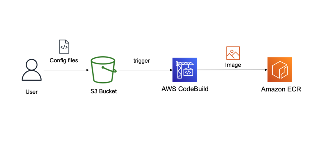
Create a customized configuration for the Conduktor Platform
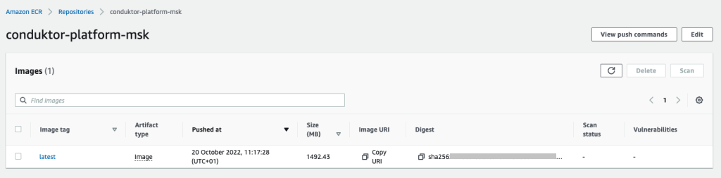
The Conduktor Platform uses a YAML configuration file to define the cluster connection endpoints. Therefore, we must create a customized Docker image of the Conduktor Platform that is able to connect to a cluster on Amazon MSK with a customized YAML file. For this, we use CodeBuild, and we store our configuration files in Amazon Simple Storage Service (Amazon S3). The final image is stored in Amazon Elastic Container Registry (Amazon ECR). The following diagram illustrates this workflow.
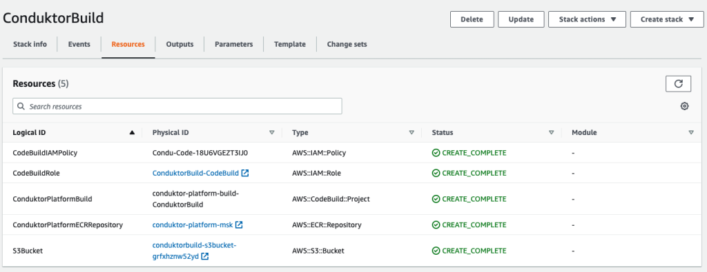
- Deploy the first CloudFormation template to create the following resources:
- An S3 bucket to store our configuration files.
- An ECR repository to store our final Docker image.
- A CodeBuild project to build that Docker image.
- An IAM role and policy to allow CodeBuild to perform the build.
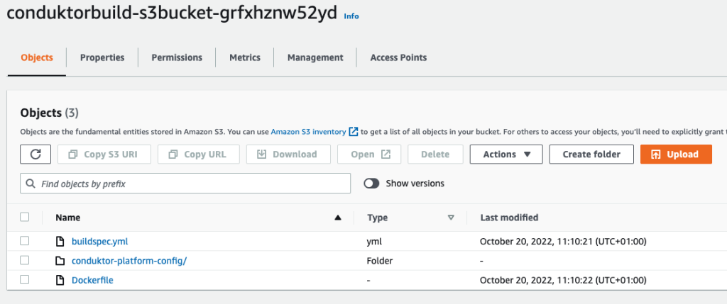
Now we need to upload our files into Amazon S3.
- Upload the following files:
- The file buildspec.yml, which is used by CodeBuild to build our primary Docker image.
- The Dockerfile, which contains instructions on how to build our final Docker image.
- The folder conduktor-platform-config (as is), which contains the configuration files to connect to Amazon MSK.
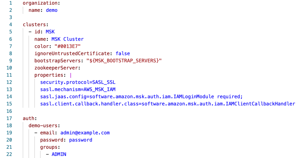
- At this stage, you can customize the
conduktor-platform.yamlfile, allowing you to connect to one MSK cluster:
Alternatively, you can connect to multiple MSK clusters or external ones by specifying multiple Kafka bootstrap servers, as shown in the following code. You can also use the same configuration file to specify the schema registry URL, Kafka Connect connection details, and SSO.
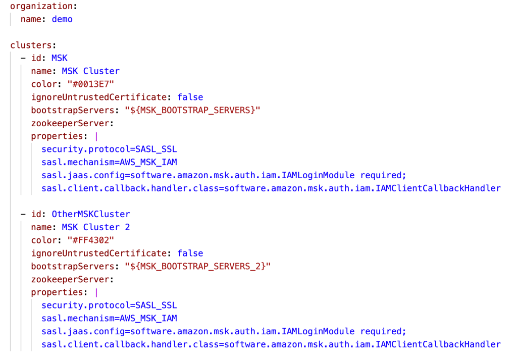
A single-Region Conduktor Platform deployment can work for multi-Region MSK clusters, although natural latency is expected. For latency-sensitive usage, you can deploy this solution in every Region in which you’re using Amazon MSK.
After uploading the files and configurations in your S3 bucket, let’s run CodeBuild to generate a new image.
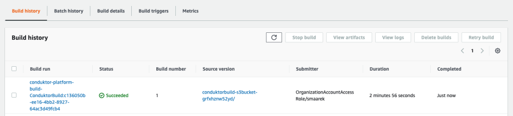
- On the CodeBuild console, navigate to the project and choose Start build.
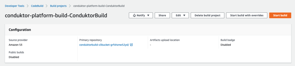
The build should complete in about 3 minutes.
The final image is pushed to Amazon ECR thanks to the script hosted in our build-spec.yml script run by CodeBuild. We’re now done with our first step. Your Conduktor Platform setup can now fully connect to your MSK cluster.
Start the MSK cluster
If you already have an MSK cluster set up with IAM access control, you can skip this step. If not, you can create one using the provided CloudFormation template.
From the MSK cluster (the new one or existing one), retrieve two essential pieces of information:
- The bootstrap servers connection string, which is accessed by choosing Client Information
- The MSK security group ID (see the following screenshot)
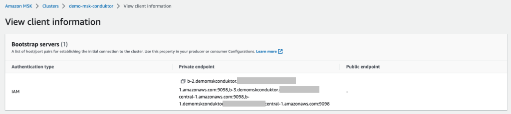
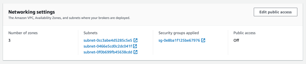
We use IAM access control so that we only need to use IAM policies to connect to our cluster.
If you’re using another security mechanism (such as SASL/SCRAM), you need to modify the Conduktor configuration files with the right properties, upload them back into Amazon S3, and rebuild the Conduktor image using CodeBuild.
Conduktor supports every single Kafka authentication method, including the ones supported by Amazon MSK: IAM access control, mutual TLS authentication, and user name/password using SASL/SCRAM.
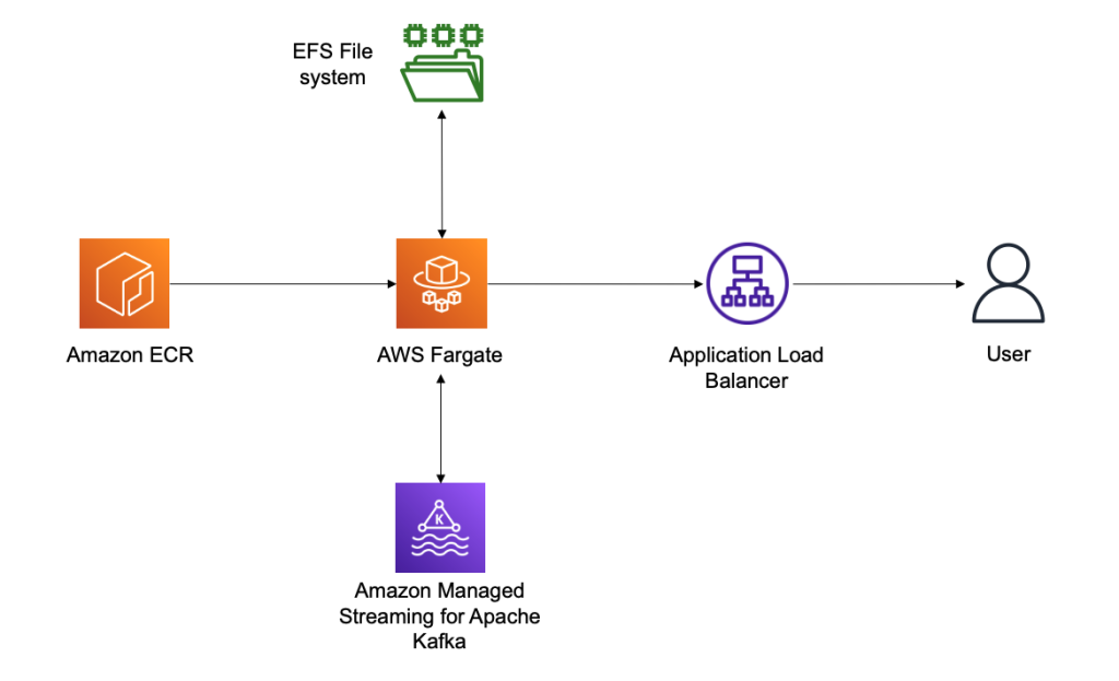
Deploy the Conduktor Platform on Amazon ECS with Fargate
The last step is to deploy the Conduktor Platform. For this, we prefer running serverless solutions using Amazon Elastic Container Service (Amazon ECS) with Fargate. This allows you to right-size your containers in the future in case your usage of Conduktor grows over time.
Conduktor stores persistent data in the /var/conduktor file system folder, to store configuration, cache computation results, store logs, and run an internal database (for example, if you start creating data masking rules). For the persistence layer, we use Amazon Elastic File System (Amazon EFS), an elastic network file system that can be mounted on Fargate to provide a persistence layer.
Finally, we expose our Fargate container through an Application Load Balancer, giving us a public static DNS endpoint to expose the Conduktor Platform and giving us complete control over the network security to access the Conduktor Platform. The following diagram illustrates our architecture.
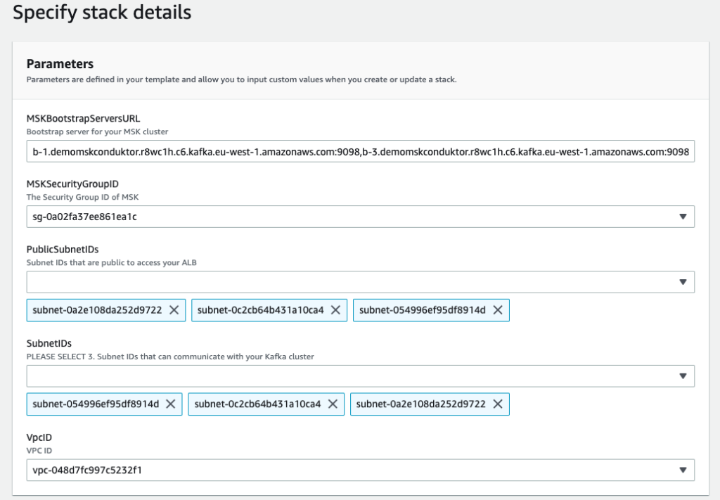
We deploy our last CloudFormation file and specify some important parameters:
- MSKBookstrapServersURL – This parameter is necessary to tell Conduktor which MSK cluster to connect to
- MSKSecurityGroupID – The MSK security group is necessary to allow the template to add a security group ingress rule to it, thereby allowing our ECS task
- PublicSubnetIDs – The public subnet IDs are for your Application Load Balancer
- SubnetIDs – The subnet IDs are for your ECS task and can be the same subnets or private subnets (as long as they have access to the MSK cluster and the other public subnets)
- VpcID – This is the VPC you’re deploying to
After deploying the template, on the Output tab of the stack, you can find the Application Load Balancer URL.
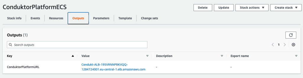
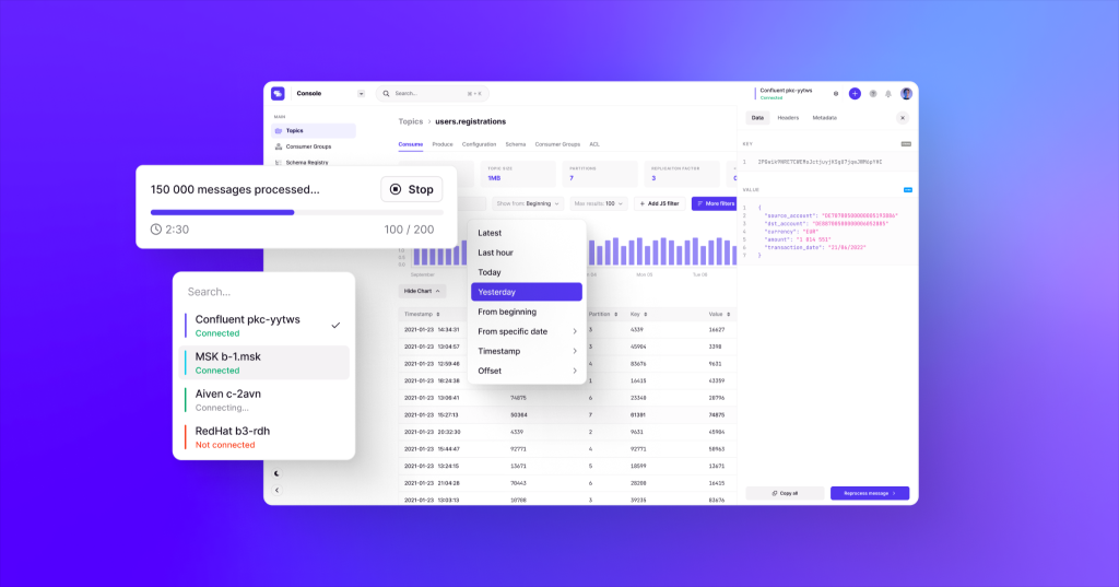
We use this URL and log in to the Conduktor Platform with the user name [email protected] and password password. These login credentials can be changed using the YAML configuration file, and you can even enable SSO and LDAP.
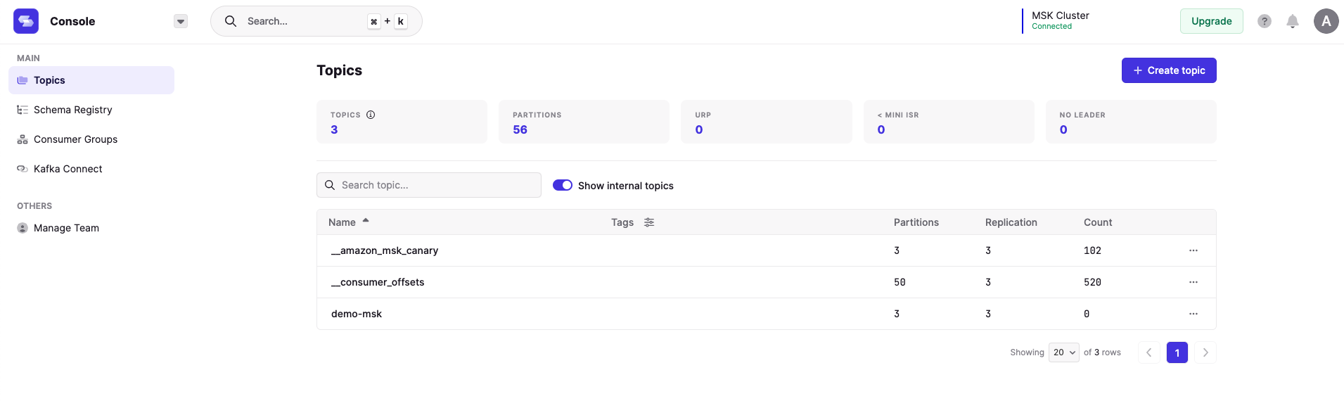
On the Conduktor console, you can start creating topics, producing data, consuming data, and much more! AWS Glue Schema Registry support is coming soon, and Confluent Schema Registry compatibility is already available.
Clean up
To clean up your AWS account, perform the following steps in order:
- Delete the third CloudFormation template (3 – create ECS Service.yaml).
- Delete the second CloudFormation template (2 – create MSK cluster.yaml).
- Empty the contents of your S3 bucket.
- Delete all your images in your ECR repository.
- Delete the first CloudFormation template (1 – base conduktor.yaml).
Conclusion
You can use the Conduktor Platform against as many MSK clusters as desired by editing the file conduktor-platform.yaml. You can even connect to your clusters running elsewhere, for example on Amazon Elastic Compute Cloud (Amazon EC2).
On our roadmap, we’re working on a complete integration with Amazon MSK, including AWS Glue Schema Registry support, Amazon MSK Connect support, and complete monitoring capabilities.
The Conduktor Platform offers a limited free tier with no time limit. Head to Conduktor’s Get Started page and create an account to start using the Platform alongside MSK clusters today.
About the Author
 Stéphane Maarek is the co-founder of Conduktor. He is also the lead instructor on Udemy for learning Apache Kafka and AWS Certifications, having taught these technologies to over 1.5 million learners. Through Conduktor, he wants to democratize access to Apache Kafka and make its usage seamless and enterprise-ready.
Amazon EMR launches support for Amazon EC2 C6i, M6i, I4i, R6i and R6id instances to improve cost performance for Spark workloads by 6–33%
Post Syndicated from Al MS original https://aws.amazon.com/blogs/big-data/amazon-emr-launches-support-for-amazon-ec2-c6i-m6i-i4i-r6i-and-r6id-instances-to-improve-cost-performance-for-spark-workloads-by-6-33/
Amazon EMR provides a managed service to easily run analytics applications using open-source frameworks such as Apache Spark, Hive, Presto, Trino, HBase, and Flink. The Amazon EMR runtime for Spark and Presto includes optimizations that provide over two times performance improvements over open-source Apache Spark and Presto, so that your applications run faster and at lower cost.
With Amazon EMR release 6.8, you can now use Amazon Elastic Compute Cloud (Amazon EC2) instances such as C6i, M6i, I4i, R6i, and R6id, which use the third-generation Intel Xeon scalable processors. Using these new instances with Amazon EMR improves cost-performance by an additional 5–33% over previous generation instances.
In this post, we describe how we estimated the cost-performance benefit from using Amazon EMR with these new instances compared to using equivalent previous generation instances.
Amazon EMR runtime performance improvements with EC2 I4i instances
We ran TPC-DS 3 TB benchmark queries on Amazon EMR 6.8 using the Amazon EMR runtime for Apache Spark (compatible with Apache Spark 3.3) with five node clusters of I4i instances with data in Amazon Simple Storage Service (Amazon S3), and compared it to equivalent sized I3 instances. We measured performance improvements using the total query runtime and geometric mean of query runtime across the TPC-DS 3 TB benchmark queries.
Our results showed between 36.41–44.39% improvement in total query runtime performance on I4i instance EMR clusters compared to equivalent I3 instance EMR clusters, and between 36–45.2% improvement in geometric mean. To measure cost improvement, we added up the Amazon EMR and Amazon EC2 cost per instance per hour (on-demand) and multiplied it by the total query runtime. Note that I4i 32XL instances were not benchmarked because I3 instances don’t have the 32 XL size available. We observed between 22.56–33.1% reduced instance hour cost on I4i instance EMR clusters compared to equivalent I3 instance EMR clusters to run the TPC-DS benchmark queries. All TPC-DS queries ran faster on I4i instance clusters compared to I3 instance clusters.
The following table shows the results from running TPC-DS 3 TB benchmark queries using Amazon EMR 6.8 over equivalent I3 and I4i instance EMR clusters.
| Instance Size | 16 XL | 8 XL | 4 XL | 2 XL | XL |
| Number of core instances in EMR cluster | 5 | 5 | 5 | 5 | 5 |
| Total query runtime on I3 (seconds) | 4752.15457 | 4506.43694 | 7110.03042 | 11853.40336 | 21333.05743 |
| Total query runtime on I4I (seconds) | 2642.77407 | 2812.05517 | 4415.0023 | 7537.52779 | 12981.20251 |
| Total query runtime improvement with I4I | 44.39% | 37.60% | 37.90% | 36.41% | 39.15% |
| Geometric mean query runtime on I3 (sec) | 34.99551 | 29.14821 | 41.53093 | 60.8069 | 95.46128 |
| Geometric mean query runtime on I4I (sec) | 19.17906 | 18.65311 | 25.66263 | 38.13503 | 56.95073 |
| Geometric mean query runtime improvement with I4I | 45.20% | 36.01% | 38.21% | 37.29% | 40.34% |
| EC2 I3 instance price ($ per hour) | $4.990 | $2.496 | $1.248 | $0.624 | $0.312 |
| EMR I3 instance price ($ per hour) | $0.270 | $0.270 | $0.270 | $0.156 | $0.078 |
| (EC2 + EMR) I3 instance price ($ per hour) | $5.260 | $2.766 | $1.518 | $0.780 | $0.390 |
| Cost of running on I3 ($ per instance) | $6.943 | $3.462 | $2.998 | $2.568 | $2.311 |
| EC2 I4I instance price ($ per hour) | $5.491 | $2.746 | $1.373 | $0.686 | $0.343 |
| EMR I4I price ($ per hour per instance) | $1.373 | $0.687 | $0.343 | $0.172 | $0.086 |
| (EC2 + EMR) I4I instance price ($ per hour) | $6.864 | $3.433 | $1.716 | $0.858 | $0.429 |
| Cost of running on I4I ($ per instance) | $5.039 | $2.681 | $2.105 | $1.795 | $1.546 |
| Total cost reduction with I4I including performance improvement | -27.43% | -22.56% | -29.79% | -30.09% | -33.10% |
The following graph shows per query improvements we observed on I4i 2XL instances with EMR Runtime for Spark on Amazon EMR version 6.8 compared to equivalent I3 2XL instances for the TPC-DS 3 TB benchmark.

Amazon EMR runtime performance improvements with EC2 M6i instances
M6i instances showed a similar performance improvement while running Apache Spark workloads compared to equivalent M5 instances. Our test results showed between 13.45–29.52% improvement in total query runtime for seven different instance sizes within the instance family, and between 7.98–25.37% improvement in geometric mean. On cost comparison, we observed 7.98–25.37% reduced instance hour cost on M6i instance EMR clusters compared to M5 EMR instance clusters to run the TPC-DS benchmark queries.
The following table shows the results from running TPC-DS 3 TB benchmark queries using Amazon EMR 6.8 over equivalent M6i and M5 instance EMR clusters.
| Instance Size | 24 XL | 16 XL | 12 XL | 8 XL | 4 XL | 2 XL | XL |
| Number of core instances in EMR cluster | 5 | 5 | 5 | 5 | 5 | 5 | 5 |
| Total query runtime on M5 (seconds) | 4027.58043 | 3782.10766 | 3348.05362 | 3516.4308 | 5621.22532 | 10075.45109 | 17278.15146 |
| Total query runtime on M6I (seconds) | 3106.43834 | 2665.70607 | 2714.69862 | 3043.5975 | 4195.02715 | 8226.88301 | 14515.50394 |
| Total query runtime improvement with M6I | 22.87% | 29.52% | 18.92% | 13.45% | 25.37% | 18.35% | 15.99% |
| Geometric mean query runtime M5 (sec) | 30.45437 | 28.5207 | 23.95314 | 23.55958 | 32.95975 | 49.43178 | 75.95984 |
| Geometric mean query runtime M6I (sec) | 23.76853 | 19.21783 | 19.16869 | 19.9574 | 24.23012 | 39.09965 | 60.79494 |
| Geometric mean query runtime improvement with M6I | 21.95% | 32.62% | 19.97% | 15.29% | 26.49% | 20.90% | 19.96% |
| EC2 M5 instance price ($ per hour) | $4.61 | $3.07 | $2.30 | $1.54 | $0.77 | $0.38 | $0.19 |
| EMR M5 instance price ($ per hour) | $0.27 | $0.27 | $0.27 | $0.27 | $0.19 | $0.10 | $0.05 |
| (EC2 + EMR) M5 instance price ($ per hour) | $4.88 | $3.34 | $2.57 | $1.81 | $0.96 | $0.48 | $0.24 |
| Cost of running on M5 ($ per instance) | $5.46 | $3.51 | $2.39 | $1.76 | $1.50 | $1.34 | $1.15 |
| EC2 M6I instance price ($ per hour) | $4.61 | $3.07 | $2.30 | $1.54 | $0.77 | $0.38 | $0.19 |
| EMR M6I price ($ per hour per instance) | $1.15 | $0.77 | $0.58 | $0.38 | $0.19 | $0.10 | $0.05 |
| (EC2 + EMR) M6I instance price ($ per hour) | $5.76 | $3.84 | $2.88 | $1.92 | $0.96 | $0.48 | $0.24 |
| Cost of running on M6I ($ per instance) | $4.97 | $2.84 | $2.17 | $1.62 | $1.12 | $1.10 | $0.97 |
| Total cost reduction with M6I including performance improvement | -8.92% | -19.02% | -9.28% | -7.98% | -25.37% | -18.35% | -15.99% |
Amazon EMR runtime performance improvements with EC2 R6i instances
R6i instances showed a similar performance improvement while running Apache Spark workloads compared to equivalent R5 instances. Our test results showed between 14.25–32.23% improvement in total query runtime for six different instance sizes within the instance family, and between 16.12–36.5% improvement in geometric mean. R5.xlarge instances didn’t have sufficient memory to run TPC-DS benchmark queries, and weren’t included in this comparison. On cost comparison, we observed 5.48–23.5% reduced instance hour cost on R6i instance EMR clusters compared to R5 EMR instance clusters to run the TPC-DS benchmark queries.
The following table shows the results from running TPC-DS 3 TB benchmark queries using Amazon EMR 6.8 over equivalent R6i and R5 instance EMR clusters.
| Instance Size | 24 XL | 16 XL | 12 XL | 8 XL | 4 XL | 2XL |
| Number of core instances in EMR cluster | 5 | 5 | 5 | 5 | 5 | 5 |
| Total query runtime on R5 (seconds) | 4024.4737 | 3715.74432 | 3552.97298 | 3535.69879 | 5379.73168 | 9121.41532 |
| Total query runtime on R6I (seconds) | 2865.83169 | 2518.24192 | 2513.4849 | 3031.71973 | 4544.44854 | 6977.9508 |
| Total query runtime improvement with R6I | 28.79% | 32.23% | 29.26% | 14.25% | 15.53% | 23.50% |
| Geometric mean query runtime R5 (sec) | 30.59066 | 28.30849 | 25.30903 | 23.85511 | 32.33391 | 47.28424 |
| Geometric mean query runtime R6I (sec) | 21.87897 | 17.97587 | 17.54117 | 20.00918 | 26.6277 | 34.52817 |
| Geometric mean query runtime improvement with R6I | 28.48% | 36.50% | 30.69% | 16.12% | 17.65% | 26.98% |
| EC2 R5 instance price ($ per hour) | $6.0480 | $4.0320 | $3.0240 | $2.0160 | $1.0080 | $0.5040 |
| EMR R5 instance price ($ per hour) | $0.2700 | $0.2700 | $0.2700 | $0.2700 | $0.2520 | $0.1260 |
| (EC2 + EMR) R5 instance price ($ per hour) | $6.3180 | $4.3020 | $3.2940 | $2.2860 | $1.2600 | $0.6300 |
| Cost of running on R5 ($ per instance) | $7.0630 | $4.4403 | $3.2510 | $2.2452 | $1.8829 | $1.5962 |
| EC2 R6I instance price ($ per hour) | $6.0480 | $4.0320 | $3.0240 | $2.0160 | $1.0080 | $0.5040 |
| EMR R6I price ($ per hour per instance) | $1.5120 | $1.0080 | $0.7560 | $0.5040 | $0.2520 | $0.1260 |
| (EC2 + EMR) R6I instance price ($ per hour) | $7.5600 | $5.0400 | $3.7800 | $2.5200 | $1.2600 | $0.6300 |
| Cost of running on R6I ($ per instance) | $6.0182 | $3.5255 | $2.6392 | $2.1222 | $1.5906 | $1.2211 |
| Total cost reduction with R6I including performance improvement | -14.79% | -20.60% | -18.82% | -5.48% | -15.53% | -23.50% |
Amazon EMR runtime performance improvements with EC2 C6i instances
C6i instances showed a similar performance improvement while running Apache Spark workloads compared to equivalent C5 instances. Our test results showed between 16.9–58.22% improvement in total query runtime for four different instance sizes within the instance family, and between 20.25–59.59% improvement in geometric mean. Only C6i 24, 12, 4, and 2xlarge sizes were benchmarked because C5 doesn’t have 32, 16 and 8 xlarge sizes. C5.xlarge instances didn’t have sufficient memory to run TPC-DS benchmark queries, and weren’t included in this comparison. On cost comparison, we observed 16.75–50.07% reduced instance hour cost on C6i instance EMR clusters compared to C5 EMR instance clusters to run the TPC-DS benchmark queries.
The following table shows the results from running TPC-DS 3 TB benchmark queries using Amazon EMR 6.8 over equivalent C6i and C5 instance EMR clusters.
| Instance Size * | 24 XL | 12 XL | 4 XL | 2 XL |
| Number of core instances in EMR cluster | 5 | 5 | 5 | 5 |
| Total query runtime on C5 (seconds) | 3435.59808 | 2900.84981 | 5945.12879 | 10173.00757 |
| Total query runtime on C6I (seconds) | 2711.16147 | 2471.86778 | 5195.30093 | 8787.43422 |
| Total query runtime improvement with C6I | 21.09% | 14.79% | 12.61% | 13.62% |
| Geometric mean query runtime C5 (sec) | 25.67058 | 20.06539 | 31.76582 | 46.78632 |
| Geometric mean query runtime C6I (sec) | 20.4458 | 17.14133 | 26.92196 | 39.32622 |
| Geometric mean query runtime improvement with C6I | 20.35% | 14.57% | 15.25% | 15.95% |
| EC2 C5 instance price ($ per hour) | $4.080 | $2.040 | $0.680 | $0.340 |
| EMR C5 instance price ($ per hour) | $0.270 | $0.270 | $0.170 | $0.085 |
| (EC2 + EMR) C5 instance price ($ per hour) | $4.35000 | $2.31000 | $0.85000 | $0.42500 |
| Cost of running on C5 ($ per instance) | $4.15135 | $1.86138 | $1.40371 | $1.20098 |
| EC2 C6I instance price ($ per hour) | $4.0800 | $2.0400 | $0.6800 | $0.3400 |
| EMR C6I price ($ per hour per instance) | $1.02000 | $0.51000 | $0.17000 | $0.08500 |
| (EC2 + EMR) C6I instance price ($ per hour) | $5.10000 | $2.55000 | $0.85000 | $0.42500 |
| Cost of running on C6I ($ per instance) | $3.84081 | $1.75091 | $1.22667 | $1.03741 |
| Total cost reduction with C6I including performance improvement | -7.48% | -5.93% | -12.61% | -13.62% |
Amazon EMR runtime performance improvements with EC2 R6id instances
R6id instances showed a similar performance improvement while running Apache Spark workloads compared to equivalent R5D instances. Our test results showed between 11.8–28.7% improvement in total query runtime for five different instance sizes within the instance family, and between 15.1–32.0% improvement in geometric mean. R6ID 32 XL instances were not benchmarked because R5D instances don’t have these sizes available. On cost comparison, we observed 6.8–11.5% reduced instance hour cost on R6ID instance EMR clusters compared to R5D EMR instance clusters to run the TPC-DS benchmark queries.
The following table shows the results from running TPC-DS 3 TB benchmark queries using Amazon EMR 6.8 over equivalent R6id and R5d instance EMR clusters.
| Instance Size | 24 XL | 16 XL | 12 XL | 8 XL | 4 XL | 2 XL | XL |
| Number of core instances in EMR cluster | 5 | 5 | 5 | 5 | 5 | 5 | 5 |
| Total query runtime on R5D (seconds) | 4054.4492975042 | 3691.7569385583 | 3598.6869168064 | 3532.7398928104 | 5397.5330161574 | 9281.2627059927 | 16862.8766838096 |
| Total query runtime on R6ID (seconds) | 2992.1198446983 | 2633.7131630720 | 2632.3186613402 | 2729.8860537867 | 4583.1040980373 | 7921.9960917943 | 14867.5391541445 |
| Total query runtime improvement with R6ID | 26.20% | 28.66% | 26.85% | 22.73% | 15.09% | 14.65% | 11.83% |
| Geometric mean query runtime R5D (sec) | 31.0238156851 | 28.1432927726 | 25.7532157307 | 24.0596427675 | 32.5800246829 | 48.2306670294 | 76.6771994376 |
| Geometric mean query runtime R6ID (sec) | 22.8681174894 | 19.1282742957 | 18.6161830746 | 18.0498249257 | 25.9500918360 | 39.6580341258 | 65.0947323858 |
| Geometric mean query runtime improvement with R6ID | 26.29% | 32.03% | 27.71% | 24.98% | 20.35% | 17.77% | 15.11% |
| EC2 R5D instance price ($ per hour) | $6.912000 | $4.608000 | $3.456000 | $2.304000 | $1.152000 | $0.576000 | $0.288000 |
| EMR R5D instance price ($ per hour) | $0.270000 | $0.270000 | $0.270000 | $0.270000 | $0.270000 | $0.144000 | $0.072000 |
| (EC2 + EMR) R5D instance price ($ per hour) | $7.182000 | $4.878000 | $3.726000 | $2.574000 | $1.422000 | $0.720000 | $0.360000 |
| Cost of running on R5D ($ per instance) | $8.088626 | $5.002331 | $3.724641 | $2.525909 | $2.132026 | $1.856253 | $1.686288 |
| EC2 R6ID instance price ($ per hour) | $7.257600 | $4.838400 | $3.628800 | $2.419200 | $1.209600 | $0.604800 | $0.302400 |
| EMR R6ID price ($ per hour per instance) | $1.814400 | $1.209600 | $0.907200 | $0.604800 | $0.302400 | $0.151200 | $0.075600 |
| (EC2 + EMR) R6ID instance price ($ per hour) | $9.072000 | $6.048000 | $4.536000 | $3.024000 | $1.512000 | $0.756000 | $0.378000 |
| Cost of running on R6ID ($ per instance) | $7.540142 | $4.424638 | $3.316722 | $2.293104 | $1.924904 | $1.663619 | $1.561092 |
| Total cost reduction with R6ID including performance improvement | -6.78% | -11.55% | -10.95% | -9.22% | -9.71% | -10.38% | -7.42% |
Benchmarking methodology
The benchmark used in this post is derived from the industry-standard TPC-DS benchmark, and uses queries from the Spark SQL Performance Tests GitHub repo with the following fixes applied.
We calculated TCO by multiplying cost per hour by number of instances in the cluster and time taken to run the queries on the cluster. We used the on-demand pricing in the US East (N. Virginia) Region for all instances.
Conclusion
In this post, we described how we estimated the cost-performance benefit from using Amazon EMR with C6i, M6i, I4i, R6i, and R6id, instances compared to using equivalent previous generation instances. Using these new instances with Amazon EMR improves cost-performance by an additional 5–33%.
About the authors
 Al MS is a product manager for Amazon EMR at Amazon Web Services.
 Kyeonghyun Ryoo is a Software Development Engineer for EMR at Amazon Web Services. He primarily works on designing and building automation tools for internal teams and customers to maximize their productivity. Outside of work, he is a retired world champion in professional gaming who still enjoy playing video games.
[$] Composefs for integrity protection and data sharing
Post Syndicated from original https://lwn.net/Articles/917097/
A read-only filesystem that will transparently share file data between disparate
directory trees, while also providing integrity verification for the data
and the
directory metadata, was recently posted as an
RFC
to the linux-kernel mailing list. Composefs was developed
by Alexander Larsson (who posted it) and Giuseppe Scrivano for use by podman containers and OSTree (or “libostree” as it
is now known) root directories, but there are likely others who want the
abilities
it provides. So far, there has been little response, either with feedback or
complaints, but it is a small patch set (around 2K lines of code) and
generally self-contained since it is a filesystem, so it would not be a
surprise to see it appear in some upcoming kernel.
GitHub Availability Report: November 2022
Post Syndicated from Jakub Oleksy original https://github.blog/2022-12-07-github-availability-report-november-2022/
In November, we experienced two incidents that resulted in degraded performance across GitHub services. This report also sheds light into an incident that impacted GitHub Codespaces in October.
November 25 16:34 UTC (lasting 1 hour and 56 minutes)
Our alerting systems detected an incident that impacted customers using GitHub Packages and Pages. Due to the recency of this incident, we are still investigating the contributing factors and will provide a more detailed update on cause and remediation in the January Availability Report, which we will publish the first Wednesday of January.
October 26 00:47 UTC (lasting 3 hours and 47 minutes)
On October 22, 2022 at 00:47 UTC, our alerting systems detected a decrease in success rates for creates and resumes of Codespaces in the East US region. We initially statused yellow, as the incident affected only the East US region. As the incident persisted for several hours, we provided guidance to customers in the affected region to manually change their location to a nearby healthy region at 01:55 UTC, and statused red at 2:34 UTC due to the prolonged outage.
During this incident, customers were unable to create or resume Codespaces in the East US region. Customers could manually select an alternate region in which to create Codespaces, but could not do so for resumes.
Codespaces uses a third-party database to store data for the service and the provider was experiencing an outage, which impacted Codespaces performance. We were unable to immediately communicate with our East US database because our service does not currently have any replication of its regional data. Our services in the East US region returned to healthy status as soon as Codespaces engineers were able to engage with the third party to help mitigate the outage.
We identified several ways to improve our database resilience to regional outages while working with the third party during this incident and in follow up internal discussions. We are implementing regional replication and failover so that we can mitigate this type of incident more quickly in the future.
November 3 16:10 UTC (lasting 1 hour and 2 minutes)
On November 3, 2022 at 16:10 UTC, our alerting systems detected an increase in the time it took GitHub Actions workflow runs to start. We initially statused GitHub Actions to red, and after assessing impact we statused to yellow at 16:11 UTC.
During this incident, customers experienced high latency in receiving webhook deliveries, starting GitHub Actions workflow runs, and receiving status updates for in-progress runs. They also experienced an increase in error responses from repositories, pull requests, Codespaces, and the GitHub API. At its peak, a majority of repositories attempting to run a GitHub Actions workflow experienced delays longer than five minutes.
GitHub Actions listens to webhooks to trigger workflow runs, and while investigating we found that the run start delays were caused by a backup in the webhooks queue. At 16:29 UTC, we scaled out and accelerated processing of the webhooks queue as a mitigation. By 17:12 UTC, the webhooks queue was fully drained and we statused back to green.
We found that the webhook delays were caused by an inefficient database query for checking repository security advisory access, which was triggered by a high volume of poorly optimized API calls. This caused a backup in background jobs running across GitHub, which is why multiple services were impacted in addition to webhooks and GitHub Actions.
Following our investigation, we fixed the inefficient query for the repository security advisory access. We also reviewed the rate limits for this particular endpoint (as well as limits in this area) to ensure they were in line with our performance expectations. Finally, we increased the default throttling of the webhooks queue to avoid potential backups in the future. As a longer-term improvement to our resiliency, we are investigating options to reduce the potential for other background jobs to impact GitHub Actions workflows. We’ll continue to run game days and conduct enhanced training for first responders to better assess impact for GitHub Actions and determine the appropriate level of statusing moving forward.
Please follow our status page for real-time updates on status changes. To learn more about what we’re working on, check out the GitHub Engineering Blog.
Let’s Architect! Optimizing the cost of your architecture
Post Syndicated from Luca Mezzalira original https://aws.amazon.com/blogs/architecture/lets-architect-optimizing-the-cost-of-your-architecture/
Written in collaboration with Ben Moses, AWS Senior Solutions Architect, and Michael Holtby, AWS Senior Manager Solutions Architecture
Designing an architecture is not a simple task. There are many dimensions and characteristics of a solution to consider, such as the availability, performance, or resilience.
In this Let’s Architect!, we explore cost optimization and ideas on how to rethink your AWS workloads, providing suggestions that span from compute to data transfer.
Migrating AWS Lambda functions to Arm-based AWS Graviton2 processors
AWS Graviton processors are custom silicon from Amazon’s Annapurna Labs. Based on the Arm processor architecture, they are optimized for performance and cost, which allows customers to get up to 34% better price performance.
This AWS Compute Blog post discusses some of the differences between the x86 and Arm architectures, as well as methods for developing Lambda functions on Graviton2, including performance benchmarking.
Many serverless workloads can benefit from Graviton2, especially when they are not using a library that requires an x86 architecture to run.
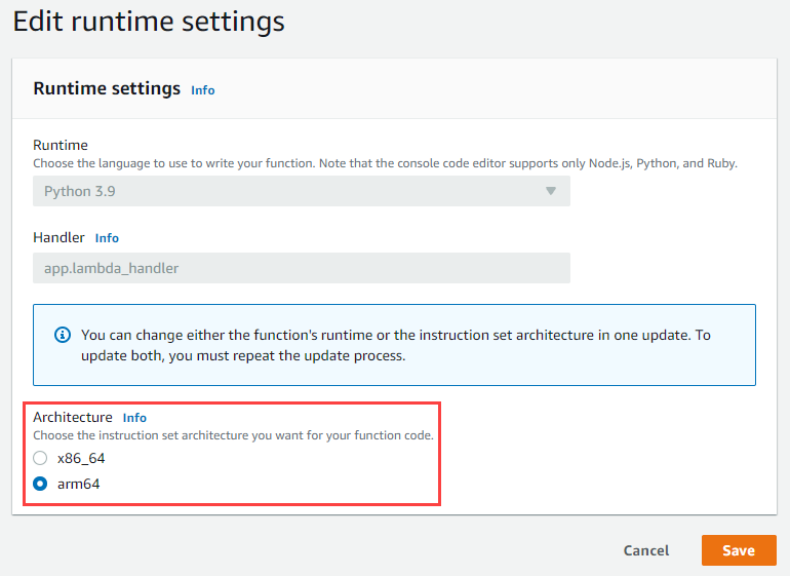
Choosing Graviton2 for AWS Lambda function in the AWS console
Key considerations in moving to Graviton2 for Amazon RDS and Amazon Aurora databases
Amazon Relational Database Service (Amazon RDS) and Amazon Aurora support a multitude of instance types to scale database workloads based on needs. Both services now support Arm-based AWS Graviton2 instances, which provide up to 52% price/performance improvement for Amazon RDS open-source databases, depending on database engine, version, and workload. They also provide up to 35% price/performance improvement for Amazon Aurora, depending on database size.
This AWS Database Blog post showcases strategies for updating RDS DB instances to make use of Graviton2 with minimal changes.
Take me to this Database post!

Choose your instance class that leverages Graviton2, such as db.r6g.large (the “g” stands for Graviton2)
Overview of Data Transfer Costs for Common Architectures
Data transfer charges are often overlooked while architecting an AWS solution. Considering data transfer charges while making architectural decisions can save costs. This AWS Architecture Blog post describes the different flows of traffic within a typical cloud architecture, showing where costs do and do not apply. For areas where cost applies, it shows best-practice strategies to minimize these expenses while retaining a healthy security posture.
Take me to this Architecture post!

Accessing AWS services in different Regions
Improve cost visibility and re-architect for cost optimization
This Architecture Blog post is a collection of best practices for cost management in AWS, including the relevant tools; plus, it is part of a series on cost optimization using an e-commerce example.
AWS Cost Explorer is used to first identify opportunities for optimizations, including data transfer, storage in Amazon Simple Storage Service and Amazon Elastic Block Store, idle resources, and the use of Graviton2 (Amazon’s Arm-based custom silicon). The post discusses establishing a FinOps culture and making use of Service Control Policies (SCPs) to control ongoing costs and guide deployment decisions, such as instance-type selection.
Take me to this Architecture post!

Applying SCPs on different environments for cost control
See you next time!
Thanks for joining us to discuss optimizing costs while architecting! This is the last Let’s Architect! post of 2022. We will see you again in 2023, when we explore even more architecture topics together.
Wishing you a happy holiday season and joyous new year!
Can’t get enough of Let’s Architect!?
Visit the Let’s Architect! page of the AWS Architecture Blog for access to the whole series.
Looking for more architecture content?
AWS Architecture Center provides reference architecture diagrams, vetted architecture solutions, Well-Architected best practices, patterns, icons, and more!
Home Assistant 2022.12 – Does Thread Matter?
Post Syndicated from BeardedTinker original https://www.youtube.com/watch?v=2ZdTIBSxXbs
Triton: Ice Volcanoes and Alien Oceans
Post Syndicated from Geographics original https://www.youtube.com/watch?v=hzcNH9HHwrE
Securing Lambda Function URLs using Amazon Cognito, Amazon CloudFront and AWS WAF
Post Syndicated from Marcia Villalba original https://aws.amazon.com/blogs/compute/securing-lambda-function-urls-using-amazon-cognito-amazon-cloudfront-and-aws-waf/
This post is written by Madhu Singh (Solutions Architect), and Krupanidhi Jay (Solutions Architect).
Lambda function URLs is a dedicated HTTPs endpoint for a AWS Lambda function. You can configure a function URL to have two methods of authentication: IAM and NONE. IAM authentication means that you are restricting access to the function URL (and in-turn access to invoke the Lambda function) to certain AWS principals (such as roles or users). Authentication type of NONE means that the Lambda function URL has no authentication and is open for anyone to invoke the function.
This blog shows how to use Lambda function URLs with an authentication type of NONE and use custom authorization logic as part of the function code, and to only allow requests that present valid Amazon Cognito credentials when invoking the function. You also learn ways to protect Lambda function URL against common security threats like DDoS using AWS WAF and Amazon CloudFront.
Lambda function URLs provides a simpler way to invoke your function using HTTP calls. However, it is not a replacement for Amazon API Gateway, which provides advanced features like request validation and rate throttling.
Solution overview
There are four core components in the example.
1. A Lambda function with function URLs enabled
At the core of the example is a Lambda function with the function URLs feature enabled with the authentication type of NONE. This function responds with a success message if a valid authorization code is passed during invocation. If not, it responds with a failure message.
2. Amazon Cognito User Pool
Amazon Cognito user pools enable user authentication on websites and mobile apps. You can also enable publicly accessible Login and Sign-Up pages in your applications using Amazon Cognito user pools’ feature called the hosted UI.
In this example, you use a user pool and the associated Hosted UI to enable user login and sign-up on the website used as entry point. This Lambda function validates the authorization code against this Amazon Cognito user pool.
3. CloudFront distribution using AWS WAF
CloudFront is a content delivery network (CDN) service that helps deliver content to end users with low latency, while also improving the security posture for your applications.
AWS WAF is a web application firewall that helps protect your web applications or APIs against common web exploits and bots and AWS Shield is a managed distributed denial of service (DDoS) protection service that safeguards applications running on AWS. AWS WAF inspects the incoming request according to the configured Web Access Control List (web ACL) rules.
Adding CloudFront in front of your Lambda function URL helps to cache content closer to the viewer, and activating AWS WAF and AWS Shield helps in increasing security posture against multiple types of attacks, including network and application layer DDoS attacks.
4. Public website that invokes the Lambda function
The example also creates a public website built on React JS and hosted in AWS Amplify as the entry point for the demo. This website works both in authenticated mode and in guest mode. For authentication, the website uses Amazon Cognito user pools hosted UI.
Solution architecture
This shows the architecture of the example and the information flow for user requests.

In the request flow:
- The entry point is the website hosted in AWS Amplify. In the home page, when you choose “sign in”, you are redirected to the Amazon Cognito hosted UI for the user pool.
- Upon successful login, Amazon Cognito returns the authorization code, which is stored as a cookie with the name “code”. The user is redirected back to the website, which has an “execute Lambda” button.
- When the user choose “execute Lambda”, the value from the “code” cookie is passed in the request body to the CloudFront distribution endpoint.
- The AWS WAF web ACL rules are configured to determine whether the request is originating from the US or Canada IP addresses and to determine if the request should be allowed to invoke Lambda function URL origin.
- Allowed requests are forwarded to the CloudFront distribution endpoint.
- CloudFront is configured to allow CORS headers and has the origin set to the Lambda function URL. The request that CloudFront receives is passed to the function URL.
- This invokes the Lambda function associated with the function URL, which validates the token.
- The function code does the following in order:
- Exchange the authorization code in the request body (passed as the event object to Lambda function) to access_token using Amazon Cognito’s token endpoint (check the documentation for more details).
- Amazon Cognito user pool’s attributes like user pool URL, Client ID and Secret are retrieved from AWS Systems Manager Parameter Store (SSM Parameters).
- These values are stored in SSM Parameter Store at the time these resources are deployed via AWS CDK (see “how to deploy” section)
- The access token is then verified to determine its authenticity.
- If valid, the Lambda function returns a message stating user is authenticated as <username> and execution was successful.
- If either the authorization code was not present, for example, the user was in “guest mode” on the website, or the code is invalid or expired, the Lambda function returns a message stating that the user is not authorized to execute the function.
- Exchange the authorization code in the request body (passed as the event object to Lambda function) to access_token using Amazon Cognito’s token endpoint (check the documentation for more details).
- The webpage displays the Lambda function return message as an alert.
Getting started
Pre-requisites:
Before deploying the solution, please follow the README from the GitHub repository and take the necessary steps to fulfill the pre-requisites.
Deploy the sample solution
1. From the code directory, download the dependencies:
$ npm install2. Start the deployment of the AWS resources required for the solution:
$ cdk deployNote:
- optionally pass in the –profile argument if needed
- The deployment can take up to 15 minutes
3. Once the deployment completes, the output looks similar to this:
Open the amplifyAppUrl from the output in your browser. This is the URL for the demo website. If you don’t see the “Welcome to Compute Blog” page, the Amplify app is still building, and the website is not available yet. Retry in a few minutes. This website works either in an authenticated or unauthenticated state.
Test the authenticated flow
- To test the authenticated flow, choose “Sign In”.

2. In the sign-in page, choose on sign-up (for the first time) and create a user name and password.
3. To use an existing an user name and password, enter those credentials and choose login.
4. Upon successful sign-in or sign up, you are redirected back to the webpage with “Execute Lambda” button.

5. Choose this button. In a few seconds, an alert pop-up shows the logged in user and that the Lambda execution is successful.
Testing the unauthenticated flow
1. To test the unauthenticated flow, from the Home page, choose “Continue”.

2. Choose “Execute Lambda” and in a few seconds, you see a message that you are not authorized to execute the Lambda function.

Testing the geo-block feature of AWS WAF
1. Access the website from a Region other than US or Canada. If you are physically in the US or Canada, you may use a VPN service to connect to a Region other than US or Canada.

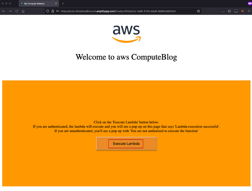
2. Choose the “Execute Lambda” button. In the Network trace of browser, you can see the call to invoke Lambda function was blocked with Forbidden response.
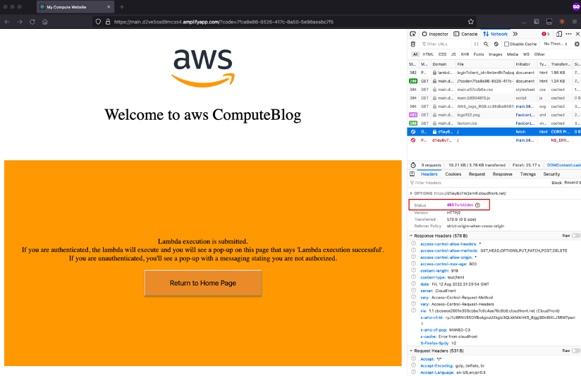
3. To try either the authenticated or unauthenticated flow again, choose “Return to Home Page” to go back to the home page with “Sign In” and “Continue” buttons.
Cleaning up
To delete the resources provisioned, run the cdk destroy command from the AWS CDK CLI.
Conclusion
In this blog, you create a Lambda function with function URLs enabled with NONE as the authentication type. You then implemented a custom authentication mechanism as part of your Lambda function code. You also increased the security of your Lambda function URL by setting it as Origin for the CloudFront distribution and using AWS WAF Geo and IP limiting rules for protection against common web threats, like DDoS.
For more serverless learning resources, visit Serverless Land.
USS California’s Four Medals of Honor
Post Syndicated from The History Guy: History Deserves to Be Remembered original https://www.youtube.com/watch?v=S-zKIdW7BRY