Tag Archives: Amazon Route 53

Disaster Recovery (DR) Architecture on AWS, Part IV: Multi-site Active/Active

Post Syndicated from Seth Eliot original https://aws.amazon.com/blogs/architecture/disaster-recovery-dr-architecture-on-aws-part-iv-multi-site-active-active/

In my first blog post of this series, I introduced you to four strategies for disaster recovery (DR). My subsequent posts shared details on the backup and restore, pilot light, and warm standby active/passive strategies.

In this post, you’ll learn how to implement an active/active strategy to run your workload and serve requests in two or more distinct sites. Like other DR strategies, this enables your workload to remain available despite disaster events such as natural disasters, technical failures, or human actions.

DR strategies: Multi-site active/active

As we know from our now familiar DR strategies diagram (Figure 1), the multi-site active/active strategy will give you the lowest RTO (recovery time objective) and RPO (recovery point objective). However, this must be weighed against the potential cost and complexity of operating active stacks in multiple sites.

DR strategies

Figure 1. DR strategies

Implementing multi-site active/active

The architecture in Figure 2 shows you how to use AWS Regions as your active sites, creating a multi-Region active/active architecture. Only two Regions are shown, which is common, but more may be used. Each Region hosts a highly available, multi-Availability Zone (AZ) workload stack. In each Region, data is replicated live between the data stores and also backed up. This protects against disasters that include data deletion or corruption, since the data backup can be restored to the last known good state.

Multi-site active/active DR strategy

Figure 2. Multi-site active/active DR strategy

Traffic routing

Each regional stack serves production traffic. How you implement traffic routing determines which Region will receive a given request. Figure 2 shows Amazon Route 53, a highly available and scalable cloud Domain Name System (DNS), used for routing. Route 53 offers multiple routing policies. For example, the geolocation or latency routing policies are good choices for active/active deployments. For geolocation routing, you configure which Region a request goes to based on the origin location of the request. For latency routing, AWS automatically sends requests to the Region that provides the shortest round-trip time.

Your data governance strategy helps inform which routing policy to use. Geolocation routing lets you distribute requests in a deterministic way. This allows you to keep data for certain users within a specific Region, or you can control where write operations are routed to prevent contention. If optimizing for performance is your top priority, then latency routing is a good choice.

Read/write patterns

Read local/write local pattern

The Region to which a request is routed is called the “local Region” for that request. To maintain low latencies and reduce the potential for network error, serve all read and write requests from the local Region of your multi-Region active/active architecture.

I use Amazon DynamoDB for the example architecture in Figure 2. DynamoDB global tables replicate a table to multiple Regions. Writes to the table in any Region are replicated to other Regions within a second. This makes it a good choice when using the read local/write local pattern. However, there is the possibility of write contention if updates are made to the same item in different Regions at about the same time. To help ensure eventual consistency, DynamoDB global tables use a last writer wins reconciliation between concurrent updates. In this case, the data written by the first writer is lost. If your application cannot handle this and you require strong consistency, use another write pattern to avoid write contention.

Read local/write global pattern

With a write global pattern, you choose a Region to be the global write Region and only accept writes in that Region. DynamoDB global tables are still an excellent choice for replicating data globally; however, you must ensure that locally received write requests are re-directed to the global write Region.

Amazon Aurora is another good choice. When deployed as an Aurora global database, a primary cluster is deployed to your global write Region, and read-only instances (Aurora Replicas) are deployed to other AWS Regions. Data is replicated to these read-only instances with typical latency of under a second. Aurora global database write forwarding (available using Aurora MySQL-Compatible Edition) allows Aurora Replicas in the secondary cluster to forward write operations to the primary cluster in the global write Region. This way, you can treat the read-only replicas in all your Regions as if they were read/write capable. Using write forwarding, the request travels over the AWS network and not the public internet, reducing latency.

Amazon ElastiCache for Redis also can replicate data across Regions. For example, to store session data, you write to your global write Region and use Global Datastore to ensure that this data is available to be read from other Regions.

Read local/write partitioned pattern

For write-heavy workloads with users located around the world, your application may not be suited to incur the round trip to the global write Region with every write. Consider using a write partitioned pattern to mitigate this. With this pattern, each item or record is assigned a home Region. This can be done based on the Region it was first written to. Or it can be based on a partition key in the record (such as user ID) by pre-assigning a home Region for each value of this key. As shown in Figure 3, records for this user are assigned to the left AWS Region as their home Region. The goal is to try to map records to a home Region close to where most write requests will originate.

Read local/write partitioned pattern for multi-site active/active DR strategy

Figure 3. Read local/write partitioned pattern for multi-site active/active DR strategy

When the user in Figure 3 travels away from home, they will read local, but writes will be routed back to their home Region. Usually writes will not incur long round trips as they are expected to typically come from near the home Region. Since writes are accepted in all Regions (for records homed to that respective Region), DynamoDB global tables, which accept writes in all Regions, are a good choice here also.

Failover

With a multi-Region active/active strategy, if your workload cannot operate in a Region, failover will route traffic away from the impacted Region to healthy Region(s). You can accomplish this with Route 53 by updating the DNS records. Make sure you set TTL (time to live) on these records low enough so that DNS resolvers will reflect your changes quickly enough to meet your RTO targets. Alternatively, you can use AWS Global Accelerator for routing and failover. It does not rely on DNS. Global Accelerator gives you two static IP addresses. You then configure which Regions user traffic goes to based on traffic dials and weights you set.

If you’re using a write global pattern and the impacted Region is the global write Region, then a new Region needs to be promoted to be the new global write Region. If you’re using a write partitioned pattern, your workload must repartition so that the records homed in the impacted Region are assigned to one of the remaining Regions. Using write local, all Regions can accept writes. With no changes needed to the data storage layer, this pattern can have the fastest (near zero) RTO.

Conclusion

Consider the multi-site active/active strategy for your workload if you need DR with the quickest recovery time (lowest RTO) and least data loss (lowest RPO). Implementing it across Regions (multi-Region) is a good option if you are looking for the most separation and complete independence of your sites, or if you need to provide low latency access to the workload from users in globally diverse locations.

Also consider the trade-offs. Implementing and operating this strategy, particularly using multi-Region, can be more complicated and more expensive, than other DR strategies. When implementing multi-Region active/active in AWS, you have access to resources to choose the routing policy and the read/write pattern that is right for your workload.

Related information

Complying with DMARC across multiple accounts using Amazon SES

Post Syndicated from Brendan Paul original https://aws.amazon.com/blogs/messaging-and-targeting/complying-with-dmarc-across-multiple-accounts-using-amazon-ses/

Introduction

For enterprises of all sizes, email is a critical piece of infrastructure that supports large volumes of communication from an organization. As such, companies need a robust solution to deal with the complexities this may introduce. In some cases, companies have multiple domains that support several different business units and need a distributed way of managing email sending for those domains. For example, you might want different business units to have the ability to send emails from subdomains, or give a marketing company the ability to send emails on your behalf. Amazon Simple Email Service (Amazon SES) is a cost-effective, flexible, and scalable email service that enables developers to send mail from any application. One of the benefits of Amazon SES is that you can configure Amazon SES to authorize other users to send emails from addresses or domains that you own (your identities) using their own AWS accounts. When allowing other accounts to send emails from your domain, it is important to ensure this is done securely. Amazon SES allows you to send emails to your users using popular authentication methods such as DMARC. In this blog, we walk you through 1/ how to comply with DMARC when using Amazon SES and 2/ how to enable other AWS accounts to send authenticated emails from your domain.

DMARC: what is it, why is it important?

DMARC stands for “Domain-based Message Authentication, Reporting & Conformance”, and it is an email authentication protocol (DMARC.org). DMARC gives domain owners and email senders a way to protect their domain from being used by malicious actors in phishing or spoofing attacks. Email spoofing can be used as a way to compromise users’ financial or personal information by taking advantage of their trust of well-known brands. DMARC makes it easier for senders and recipients to determine whether or not an email was actually sent by the domain that it claims to have been sent by.

Solution Overview

In this solution, you will learn how to set up DKIM signing on Amazon SES, implement a DMARC Policy, and enable other accounts in your organization to send emails from your domain using Sending Authorization. When you set up DKIM signing, Amazon SES will attach a digital signature to all outgoing messages, allowing recipients to verify that the email came from your domain. You will then set your DMARC Policy, which tells an email receiver what to do if an email is not authenticated. Lastly, you will set up Sending Authorization so that other AWS accounts can send authenticated emails from your domain.

Prerequisites

In order to complete the example illustrated in this blog post, you will need to have:

  1. A domain in an Amazon Route53 Hosted Zone or third-party provider. Note: You will need to add/update records for the domain. For this blog we will be using Route53.
  2. An AWS Organization
  3. A second AWS account to send Amazon SES Emails within a different AWS Organizations OU. If you have not worked with AWS Organizations before, review the Organizations Getting Started Guide

How to comply with DMARC (DKIM and SPF) in Amazon SES

In order to comply with DMARC, you must authenticate your messages with either DKIM (DomainKeys Identified Mail), SPF (Sender Policy Framework), or both. DKIM allows you to send email messages with a cryptographic key, which enables email providers to determine whether or not the email is authentic. SPF defines what servers are allowed to send emails for their domain. To use SPF for DMARC compliance you need to set up a custom MAIL FROM domain in Amazon SES. To authenticate your emails with DKIM in Amazon SES, you have the option of:

In this blog, you will be setting up a sending identity.

Setting up DKIM Signing in Amazon SES

  1. Navigate to the Amazon SES Console 
  2. Select Verify a New Domain and type the name of your domain in
  3. Select Generate DKIM Settings
  4. Choose Verify This Domain
    1. This will generate the DNS records needed to complete domain verification, DKIM signing, and routing incoming mail.
    2. Note: When you initiate domain verification using the Amazon SES console or API, Amazon SES gives you the name and value to use for the TXT record. Add a TXT record to your domain’s DNS server using the specified Name and Value. Amazon SES domain verification is complete when Amazon SES detects the existence of the TXT record in your domain’s DNS settings.
  5. If you are using Route 53 as your DNS provider, choose the Use Route 53 button to update the DNS records automatically
    1. If you are not using Route 53, go to your third-party provider and add the TXT record to verify the domain as well as the three CNAME records to enable DKIM signing. You can also add the MX record at the end to route incoming mail to Amazon SES.
    2. A list of common DNS Providers and instructions on how to update the DNS records can be found in the Amazon SES documentation
  6. Choose Create Record Sets if you are using Route53 as shown below or choose Close after you have added the necessary records to your third-party DNS provider.


Note: in the case that you previously verified a domain, but did NOT generate the DKIM settings for your domain, follow the steps below. Skip these steps if this is not the case:

  1. Go to the Amazon SES Console, and select your domain
  2. Select the DKIM dropdown
  3. Choose Generate DKIM Settings and copy the three values in the record set shown
    1. You may also download the record set as a CSV file
  4. Navigate to the Route53 console or your third-party DNS provider. Instructions on how to update the DNS records in your third-party can be found in the Amazon SES documentation
  5. Select the domain you are using
  6. Choose Create Record

  1. Enter the values that Amazon SES has generated for you, and add the three CNAME records to your domain
  2. Wait a few minutes, and go back to your domain in the Amazon SES Console
  3. Check that the DKIM status is verified

You also want to set up a custom MAIL FROM domain that you will use later on. To do so, follow the steps in the documentation.

Setting up a DMARC policy on your domain

DMARC policies are TXT records you place in DNS to define what happens to incoming emails that don’t align with the validations provided when setting up DKIM and SPF. With this policy, you can choose to allow the email to pass through, quarantine the email into a folder like junk or spam, or reject the email.

As a best practice, you should start with a DMARC policy that doesn’t reject all email traffic and collect reports on emails that don’t align to determine if they should be allowed. You can also set a percentage on the DMARC policy to perform filtering on a subset of emails to, for example, quarantine only 50% of the emails that don’t align. Once you are in a state where you can begin to reject non-compliant emails, flip the policy to reject failed authentications. When you set the DMARC policy for your domain, any subdomains that are authorized to send on behalf of your domain will inherit this policy and the same rule will apply. For more information on setting up a DMARC policy, see our documentation.

In a scenario where you have multiple subdomains sending emails, you should be setting the DMARC policy for the organizational domain that you own. For example, if you own the domain example.com and also want to use the sub-domain sender.example.com to send emails you can set the organizational DMARC policy (as a DNS TXT record) to:

Name Type Value
1 _dmarc.example.com TXT “v=DMARC1;p=quarantine;pct=50;rua=mailto:[email protected]

This DMARC policy states that 50% of emails coming from example.com that fail authentication should be quarantined and you want to send a report of those failures to [email protected]. For your sender.example.com sub-domain, this policy will be inherited unless you specify another DMARC policy for our sub-domain. In the case where you want to be stricter on the sub-domain you could add another DMARC policy like you see in the following table.


Name Type Value
1 _dmarc.sender.example.com TXT “v=DMARC1;p=reject;pct=100;rua=mailto:[email protected];ruf=mailto:[email protected]

This policy would apply to emails coming from sender.example.com and would reject any email that fails authentication. It would also send aggregate feedback to [email protected] and detailed message-specific failure information to [email protected] for further analysis.

Sending Authorization in Amazon SES – Allowing Other Accounts to Send Authenticated Emails

Now that you have configured Amazon SES to comply with DMARC in the account that owns your identity, you may want to allow other accounts in your organization the ability to send emails in the same way. Using Sending Authorization, you can authorize other users or accounts to send emails from identities that you own and manage. An example of where this could be useful is if you are an organization which has different business units in that organization. Using sending authorization, a business unit’s application could send emails to their customers from the top-level domain. This application would be able to leverage the authentication settings of the identity owner without additional configuration. Another advantage is that if the business unit has its own subdomain, the top-level domain’s DKIM settings can apply to this subdomain, so long as you are using Easy DKIM in Amazon SES and have not set up Easy DKIM for the specific subdomains.

Setting up sending authorization across accounts

Before you set up sending authorization, note that working across multiple accounts can impact bounces, complaints, pricing, and quotas in Amazon SES. Amazon SES documentation provides a good understanding of the impacts when using multiple accounts. Specifically, delegated senders are responsible for bounces and complaints and can set up notifications to monitor such activities. These also count against the delegated senders account quotas. To set up Sending Authorization across accounts:

  1. Navigate to the Amazon SES Console from the account that owns the Domain
  2. Select Domains under Identity Management
  3. Select the domain that you want to set up sending authorization with
  4. Select View Details
  5. Expand Identity Policies and Click Create Policy
  6. You can either create a policy using the policy generator or create a custom policy. For the purposes of this blog, you will create a custom policy.
  7. For the custom policy, you will allow a particular Organization Unit (OU) from our AWS Organization access to our domain. You can also limit access to particular accounts or other IAM principals. Use the following policy to allow a particular OU to access the domain:

{
  “Version”: “2012-10-17”,
  “Id”: “AuthPolicy”,
  “Statement”: [
    {
      “Sid”: “AuthorizeOU”,
      “Effect”: “Allow”,
      “Principal”: “*”,
      “Action”: [
        “SES:SendEmail”,
        “SES:SendRawEmail”
      ],
      “Resource”: “<Arn of Verified Domain>”,
      “Condition”: {
        “ForAnyValue:StringLike”: {
          “aws:PrincipalOrgPaths”: “<Organization Id>/<Root OU Id>/<Organizational Unit Id>”
        }
      }
    }
  ]
}

9. Make sure to replace the escaped values with your Verified Domain ARN and the Org path of the OU you want to limit access to.


You can find more policy examples in the documentation. Note that you can configure sending authorization such that all accounts under your AWS Organization are authorized to send via a certain subdomain.

Testing

You can now test the ability to send emails from your domain in a different AWS account. You will do this by creating a Lambda function to send a test email. Before you create the Lambda function, you will need to create an IAM role for the Lambda function to use.

Creating the IAM Role:

  1. Log in to your separate AWS account
  2. Navigate to the IAM Management Console
  3. Select Role and choose Create Role
  4. Under Choose a use case select Lambda
  5. choose Next: Permissions
  6. In the search bar, type SES and select the check box next to AmazonSESFullAccess
  7. Choose Next:Tags and Review
  8. Give the role a name of your choosing, and choose Create Role

Navigate to Lambda Console

  1. Select Create Function
  2. Choose the box marked Author from Scratch
  3. Give the function a name of your choosing (Ex: TestSESfunction)
  4. In this demo, you will be using Python 3.8 runtime, but feel free to modify to your language of choice
  5. Select the Change default execution role dropdown, and choose the Use an existing role radio button
  6. Under Existing Role, choose the role that you created in the previous step, and create the function

Edit the function

  1. Navigate to the Function Code portion of the page and open the function python file
  2. Replace the default code with the code shown below, ensuring that you put your own values in based on your resources
  3. Values needed:
    1. Test Email Address: an email address you have access to
      1. NOTE: If you are still operating in the Amazon SES Sandbox, this will need to be a verified email in Amazon SES. To verify an email in Amazon SES, follow the process here. Alternatively, here is how you can move out of the Amazon SES Sandbox
    2. SourceArn: The arn of your domain. This can be found in Amazon SES Console → Domains → <YourDomain> → Identity ARN
    3. ReturnPathArn: The same as your Source ARN
    4. Source: This should be your Mail FROM Domain @ your domain
      1. Your Mail FROM Domain can be found under Domains → <YourDomain> → Mail FROM Domain dropdown
      2. Ex: [email protected]
    5. Use the following function code for this example

import json
import boto3
from botocore.exceptions import ClientError

client = boto3.client('ses')
def lambda_handler(event, context):
    # Try to send the email.
    try:
        #Provide the contents of the email.
        response = client.send_email(
            Destination={
                'ToAddresses': [
                    '<[email protected]>',
                ],
            },
            Message={
                'Body': {
                    'Html': {
                        'Charset': 'UTF-8',
                        'Data': 'This email was sent with Amazon SES.',
                    },
                },
                'Subject': {
                    'Charset': 'UTF-8',
                    'Data': 'Amazon SES Test',
                },
            },
            SourceArn='<your-ses-identity-ARN>',
            ReturnPathArn='<your-ses-identity-ARN>',
            Source='<[email protected]>',
             )
    # Display an error if something goes wrong.
    except ClientError as e:
        print(e.response['Error']['Message'])
    else:
        print("Email sent! Message ID:"),
        print(response['ResponseMetadata']['RequestId'])

  1. Once you have replaced the appropriate values, choose the Deploy button to deploy your changes

Run a Test invocation

  1. After you have deployed your changes, select the “Test” Panel above your function code

  1. You can leave all of these keys and values as default, as the function does not use any event parameters
  2. Choose the Invoke button in the top right corner
  3. You should see this above the test event window:

Verifying that the Email has been signed properly

Depending on your email provider, you may be able to check the DKIM signature directly in the application. As an example, for Outlook, right click on the message, and choose View Source from the menu. You should see line that shows the Authentication Results and whether or not the DKIM/SPF signature passed. For Gmail, go to your Gmail Inbox on the Gmail web app. Choose the message you wish to inspect, and choose the More Icon. Choose View Original from the drop-down menu. You should then see the SPF and DKIM “PASS” Results.

Cleanup

To clean up the resources in your account,

  1. Navigate to the Route53 Console
  2. Select the Hosted Zone you have been working with
  3. Select the CNAME, TXT, and MX records that you created earlier in this blog and delete them
  4. Navigate to the SES Console
  5. Select Domains
  6. Select the Domain that you have been working with
  7. Click the drop down Identity Policies and delete the one that you created in this blog
  8. If you verified a domain for the sake of this blog: navigate to the Domains tab, select the domain and select Remove
  9. Navigate to the Lambda Console
  10. Select Functions
  11. Select the function that you created in this exercise
  12. Select Actions and delete the function

Conclusion

In this blog post, we demonstrated how to delegate sending and management of your sub-domains to other AWS accounts while also complying with DMARC when using Amazon SES. In order to do this, you set up a sending identity so that Amazon SES automatically adds a DKIM signature to your messages. Additionally, you created a custom MAIL FROM domain to comply with SPF. Lastly, you authorized another AWS account to send emails from a sub-domain managed in a different account, and tested this using a Lambda function. Allowing other accounts the ability to manage and send email from your sub-domains provides flexibility and scalability for your organization without compromising on security.

Now that you have set up DMARC authentication for multiple accounts in your enviornment, head to the AWS Messaging & Targeting Blog to see examples of how you can combine Amazon SES with other AWS Services!

If you have more questions about Amazon Simple Email Service, check out our FAQs or our Developer Guide.

If you have feedback about this post, submit comments in the Comments section below.

Using Route 53 Private Hosted Zones for Cross-account Multi-region Architectures

Post Syndicated from Anandprasanna Gaitonde original https://aws.amazon.com/blogs/architecture/using-route-53-private-hosted-zones-for-cross-account-multi-region-architectures/

This post was co-written by Anandprasanna Gaitonde, AWS Solutions Architect and John Bickle, Senior Technical Account Manager, AWS Enterprise Support

Introduction

Many AWS customers have internal business applications spread over multiple AWS accounts and on-premises to support different business units. In such environments, you may find a consistent view of DNS records and domain names between on-premises and different AWS accounts useful. Route 53 Private Hosted Zones (PHZs) and Resolver endpoints on AWS create an architecture best practice for centralized DNS in hybrid cloud environment. Your business units can use flexibility and autonomy to manage the hosted zones for their applications and support multi-region application environments for disaster recovery (DR) purposes.

This blog presents an architecture that provides a unified view of the DNS while allowing different AWS accounts to manage subdomains. It utilizes PHZs with overlapping namespaces and cross-account multi-region VPC association for PHZs to create an efficient, scalable, and highly available architecture for DNS.

Architecture Overview

You can set up a multi-account environment using services such as AWS Control Tower to host applications and workloads from different business units in separate AWS accounts. However, these applications have to conform to a naming scheme based on organization policies and simpler management of DNS hierarchy. As a best practice, the integration with on-premises DNS is done by configuring Amazon Route 53 Resolver endpoints in a shared networking account. Following is an example of this architecture.

Route 53 PHZs and Resolver Endpoints

Figure 1 – Architecture Diagram

The customer in this example has on-premises applications under the customer.local domain. Applications hosted in AWS use subdomain delegation to aws.customer.local. The example here shows three applications that belong to three different teams, and those environments are located in their separate AWS accounts to allow for autonomy and flexibility. This architecture pattern follows the option of the “Multi-Account Decentralized” model as described in the whitepaper Hybrid Cloud DNS options for Amazon VPC.

This architecture involves three key components:

1. PHZ configuration: PHZ for the subdomain aws.customer.local is created in the shared Networking account. This is to support centralized management of PHZ for ancillary applications where teams don’t want individual control (Item 1a in Figure). However, for the key business applications, each of the teams or business units creates its own PHZ. For example, app1.aws.customer.local – Application1 in Account A, app2.aws.customer.local – Application2 in Account B, app3.aws.customer.local – Application3 in Account C (Items 1b in Figure). Application1 is a critical business application and has stringent DR requirements. A DR environment of this application is also created in us-west-2.

For a consistent view of DNS and efficient DNS query routing between the AWS accounts and on-premises, best practice is to associate all the PHZs to the Networking Account. PHZs created in Account A, B and C are associated with VPC in Networking Account by using cross-account association of Private Hosted Zones with VPCs. This creates overlapping domains from multiple PHZs for the VPCs of the networking account. It also overlaps with the parent sub-domain PHZ (aws.customer.local) in the Networking account. In such cases where there is two or more PHZ with overlapping namespaces, Route 53 resolver routes traffic based on most specific match as described in the Developer Guide.

2. Route 53 Resolver endpoints for on-premises integration (Item 2 in Figure): The networking account is used to set up the integration with on-premises DNS using Route 53 Resolver endpoints as shown in Resolving DNS queries between VPC and your network. Inbound and Outbound Route 53 Resolver endpoints are created in the VPC in us-east-1 to serve as the integration between on-premises DNS and AWS. The DNS traffic between on-premises to AWS requires an AWS Site2Site VPN connection or AWS Direct Connect connection to carry DNS and application traffic. For each Resolver endpoint, two or more IP addresses can be specified to map to different Availability Zones (AZs). This helps create a highly available architecture.
3. Route 53 Resolver rules (Item 3 in Figure): Forwarding rules are created only in the networking account to route DNS queries for on-premises domains (customer.local) to the on-premises DNS server. AWS Resource Access Manager (RAM) is used to share the rules to accounts A, B and C as mentioned in the section “Sharing forwarding rules with other AWS accounts and using shared rules” in the documentation. Account owners can now associate these shared rules with their VPCs the same way that they associate rules created in their own AWS accounts. If you share the rule with another AWS account, you also indirectly share the outbound endpoint that you specify in the rule as described in the section “Considerations when creating inbound and outbound endpoints” in the documentation. This implies that you use one outbound endpoint in a region to forward DNS queries to your on-premises network from multiple VPCs, even if the VPCs were created in different AWS accounts. Resolver starts to forward DNS queries for the domain name that’s specified in the rule to the outbound endpoint and forward to the on-premises DNS servers. The rules are created in both regions in this architecture.

This architecture provides the following benefits:

  1. Resilient and scalable
  2. Uses the VPC+2 endpoint, local caching and Availability Zone (AZ) isolation
  3. Minimal forwarding hops
  4. Lower cost: optimal use of Resolver endpoints and forwarding rules

In order to handle the DR, here are some other considerations:

  • For app1.aws.customer.local, the same PHZ is associated with VPC in us-west-2 region. While VPCs are regional, the PHZ is a global construct. The same PHZ is accessible from VPCs in different regions.
  • Failover routing policy is set up in the PHZ and failover records are created. However, Route 53 health checkers (being outside of the VPC) require a public IP for your applications. As these business applications are internal to the organization, a metric-based health check with Amazon CloudWatch can be configured as mentioned in Configuring failover in a private hosted zone.
  • Resolver endpoints are created in VPC in another region (us-west-2) in the networking account. This allows on-premises servers to failover to these secondary Resolver inbound endpoints in case the region goes down.
  • A second set of forwarding rules is created in the networking account, which uses the outbound endpoint in us-west-2. These are shared with Account A and then associated with VPC in us-west-2.
  • In addition, to have DR across multiple on-premises locations, the on-premises servers should have a secondary backup DNS on-premises as well (not shown in the diagram).
    This ensures a simple DNS architecture for the DR setup, and seamless failover for applications in case of a region failure.

Considerations

  • If Application 1 needs to communicate to Application 2, then the PHZ from Account A must be shared with Account B. DNS queries can then be routed efficiently for those VPCs in different accounts.
  • Create additional IP addresses in a single AZ/subnet for the resolver endpoints, to handle large volumes of DNS traffic.
  • Look at Considerations while using Private Hosted Zones before implementing such architectures in your AWS environment.

Summary

Hybrid cloud environments can utilize the features of Route 53 Private Hosted Zones such as overlapping namespaces and the ability to perform cross-account and multi-region VPC association. This creates a unified DNS view for your application environments. The architecture allows for scalability and high availability for business applications.

The Satellite Ear Tag that is Changing Cattle Management

Post Syndicated from Karen Hildebrand original https://aws.amazon.com/blogs/architecture/the-satellite-ear-tag-that-is-changing-cattle-management/

Most cattle are not raised in cities—they live on cattle stations, large open plains, and tracts of land largely unpopulated by humans. It’s hard to keep connected with the herd. Cattle don’t often carry their own mobile phones, and they don’t pay a mobile phone bill. Naturally, the areas in which cattle live, often do not have cellular connectivity or reception. But they now have one way to stay connected: a world-first satellite ear tag.

Ceres Tag co-founders Melita Smith and David Smith recognized the problem given their own farming background. David explained that they needed to know simple things to begin with, such as:

  • Where are they?
  • How many are out there?
  • What are they doing?
  • What condition are they in?
  • Are they OK?

Later, the questions advanced to:

  • Which are the higher performing animals that I want to keep?
  • Where do I start when rounding them up?
  • As assets, can I get better financing and insurance if I can prove their location, existence, and condition?

To answer these questions, Ceres Tag first had to solve the biggest challenge, and it was not to get cattle to carry their mobile phones and pay mobile phone bills to generate the revenue needed to get greater coverage. David and Melita knew they needed help developing a new method of tracking, but in a way that aligned with current livestock practices. Their idea of a satellite connected ear tag came to life through close partnership and collaboration with CSIRO, Australia’s national science agency. They brought expertise to the problem, and rallied together teams of experts across public and private partnerships, never accepting “that’s not been done before” as a reason to curtail their innovation.


Figure 1: How Ceres Tag works in practice

Thinking Big: Ceres Tag Protocol

Melita and David constructed their idea and brought the physical hardware to reality. This meant finding strategic partners to build hardware, connectivity partners that provided global coverage at a cost that was tenable to cattle operators, integrations with existing herd management platforms and a global infrastructure backbone that allowed their solution to scale. They showed resilience, tenacity and persistence that are often traits attributed to startup founders and lifelong agricultural advocates. Explaining the purpose of the product often requires some unique approaches to defining the value proposition while fundamentally breaking down existing ways of thinking about things. As David explained, “We have an internal saying, ‘As per Ceres Tag protocol …..’ to help people to see the problem through a new lens.” This persistence led to the creation of an easy to use ear tagging applicator and a two-prong smart ear tag. The ear tag connects via satellite for data transmission, providing connectivity to more than 120 countries in the world and 80% of the earth’s surface.

The Ceres Tag applicator, smart tag, and global satellite connectivity

Figure 2: The Ceres Tag applicator, smart tag, and global satellite connectivity

Unlocking the blocker: data-driven insights

With the hardware and connectivity challenges solved, Ceres Tag turned to how the data driven insights would be delivered. The company needed to select a technology partner that understood their global customer base, and what it means to deliver a low latency solution for web, mobile and API-driven solutions. David, once again knew the power in leveraging the team around him to find the best solution. The evaluation of cloud providers was led by Lewis Frost, COO, and Heidi Perrett, Data Platform Manager. Ceres Tag ultimately chose to partner with AWS and use the AWS Cloud as the backbone for the Ceres Tag Management System.

Ceres Tag conceptual diagram

Figure 3: Ceres Tag conceptual diagram

The Ceres Tag Management System houses the data and metadata about each tag, enabling the traceability of that tag throughout each animal’s life cycle. This includes verification as to whom should have access to their health records and history. Based on the nature of the data being stored and transmitted, security of the application is critical. As a startup, it was important for Ceres Tag to keep costs low, but to also to be able to scale based on growth and usage as it expands globally.

Ceres Tag is able to quickly respond to customers regardless of geography, routing traffic to the appropriate end point. They accomplish this by leveraging Amazon CloudFront as the Content Delivery Network (CDN) for traffic distribution of front-end requests and Amazon Route 53 for DNS routing. A multi-Availability Zone deployment and AWS Application Load Balancer distribute incoming traffic across multiple targets, increasing the availability of your application.

Ceres Tag is using AWS Fargate to provide a serverless compute environment that matches the pay-as-you-go usage-based model. AWS also provides many advanced security features and architecture guidance that has helped to implement and evaluate best practice security posture across all of the environments. Authentication is handled by Amazon Cognito, which allows Ceres Tag to scale easily by supporting millions of users. It leverages easy-to-use features like sign-in with social identity providers, such as Facebook, Google, and Amazon, and enterprise identity providers via SAML 2.0.

The data captured from the ear tag on the cattle is will be ingested via AWS PrivateLink. By providing a private endpoint to access your services, AWS PrivateLink ensures your traffic is not exposed to the public internet. It also makes it easy to connect services across different accounts and VPCs to significantly simplify your network architecture. In leveraging a satellite connectivity provider running on AWS, Ceres Tag will benefit from the AWS Ground Station infrastructure leveraged by the provider in addition to the streaming IoT database.


Agile website delivery with Hugo and AWS Amplify

Post Syndicated from Nigel Harris original https://aws.amazon.com/blogs/devops/agile-website-delivery-with-hugo-and-aws-amplify/

In this post, we show how you can rapidly configure and deploy a website using Hugo (an AWS Cloud9 integrated development environment (IDE) for content editing), AWS CodeCommit for source code control, and AWS Amplify to implement a source code-controlled, automated deployment process.

When hosting a website on AWS, you can choose from several options. One popular option is to use Amazon Simple Storage Service (Amazon S3) to host a static website. If you prefer full access to the infrastructure hosting your website, you can use the NGINX Quick Start to quickly deploy web server infrastructure using AWS CloudFormation.

Static website generators such as Hugo and MkDocs accelerate the website content generation process, and can be a valuable tool when trying to rapidly deliver technical documentation or similar content. Typically, the content creation process requires programming in HTML and CSS.

Hugo is written in Go and available under the Apache 2.0 license. It provides several themes (collections of layouts) that accelerate website creation by drastically reducing the need to focus on format. You can author content in Markdown and output in multiple languages and formats (including ebook formats). Excellent examples of public websites built using Hugo include Digital.gov and Kubernetes.io.


Solution overview

This solution illustrates how to provision a hosted, source code-controlled Hugo generated website using CodeCommit and Amplify Console. The provisioned website is configured with a custom subdomain and an SSL certificate. We use an AWS Cloud9 IDE to enable content creation in the cloud.


Setting up an AWS Cloud9 IDE

Start by provisioning an AWS Cloud9 IDE. AWS Cloud9 environments run using Amazon Elastic Compute Cloud (Amazon EC2). You need to provision your AWS Cloud9 environment into an existing public subnet in an Amazon Virtual Private Cloud (Amazon VPC) within your AWS account. You can complete this in the following steps:

1. Access your AWS account using with an identity with administrative privileges. If you don’t have an AWS account, you can create one.

2. Create a new AWS Cloud9 environment using the wizard on the AWS Cloud9 console.

3. Enter a name for your desktop and an optional description.

4. Choose Next step.

Naming your Cloud 9 environment

5. In the Environment settings section, for Environment type, select Create a new EC2 instance for environment (direct access).

6. For Instance type, select your preferred instance type (the default, t2.micro, works for this use case)

7. Under Network settings, for Network (VPC), choose a VPC that you wish to deploy your AWS Cloud9 instance into. You may wish to use your default VPC, which is suitable for the purpose of this tutorial.

8. Choose a public subnet from this VPC for deployment.

Cloud9 Settings

9. Leave all other settings unchanged and choose Next step.
10. Review your choices and choose Create environment.

Environment creation takes a few minutes to complete. When the environment is ready, you receive access to the AWS Cloud9 IDE in your browser. We return to it shortly to develop content for your Hugo website.

Your Cloud9 Desktop

Configuring a source code repository to track content changes

Static website generators enable rapid changes to website content and layout. Source control management (SCM) systems provide a revision history for your code, and allow you to revert to previous versions of a project when unintended changes are introduced. SCM systems become increasingly important as the velocity of change and the number of team members introducing change increases.

You now create a source code repository to track changes to your content. You use CodeCommit, a fully-managed source control service that hosts secure Git-based repositories.

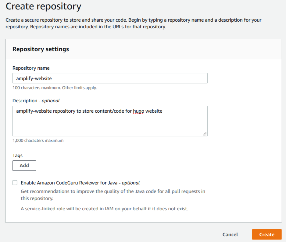
1. In a new browser, sign in to the CodeCommit Console and create a new repository.

2. For Repository name, enter amplify-website.

3. For Description, enter an appropriate description.

4. Choose Create.

Create repository

Repository creation takes just a few moments.

5. In the Connection steps section, choose the appropriate method to connect to your repository based on how you accessed your AWS account.

For this post, I signed in to my AWS account using federated access, so I choose the HTTPS Git Remote CodeCommit (HTTPS-GRC) tab. This is the recommended connection method for this sign-in type. You can also configure a connection to your repository using SSH or Git credentials over HTTPS. SSH and Git credentials over HTTPS are appropriate methods if you have signed in to your AWS account as an AWS Identity and Access Management (IAM) user. The Amazon CodeCommit console provides additional information regarding each of these connection types, including links to supporting documentation.

Connect to Repo


Configuring and deploying an example website

You’re now ready to configure and deploy your website.

1. Return to the browser with your AWS Cloud9 IDE and place your cursor in the lower terminal pane of the IDE.

The terminal pane provides Bash shell access on the EC2 instance running AWS Cloud9.

You now create a Hugo website. The website design is based on Hugo-theme-learn. Themes are collections of Hugo layouts that take all the hassle out of building your website. Learn is a multilingual-ready theme authored by Mathieu Cornic, designed for building technical documentation websites.

Hugo provides a variety of themes on their website. Many of the themes include bundled example website content that you can easily adapt by following the accompanying theme documentation.

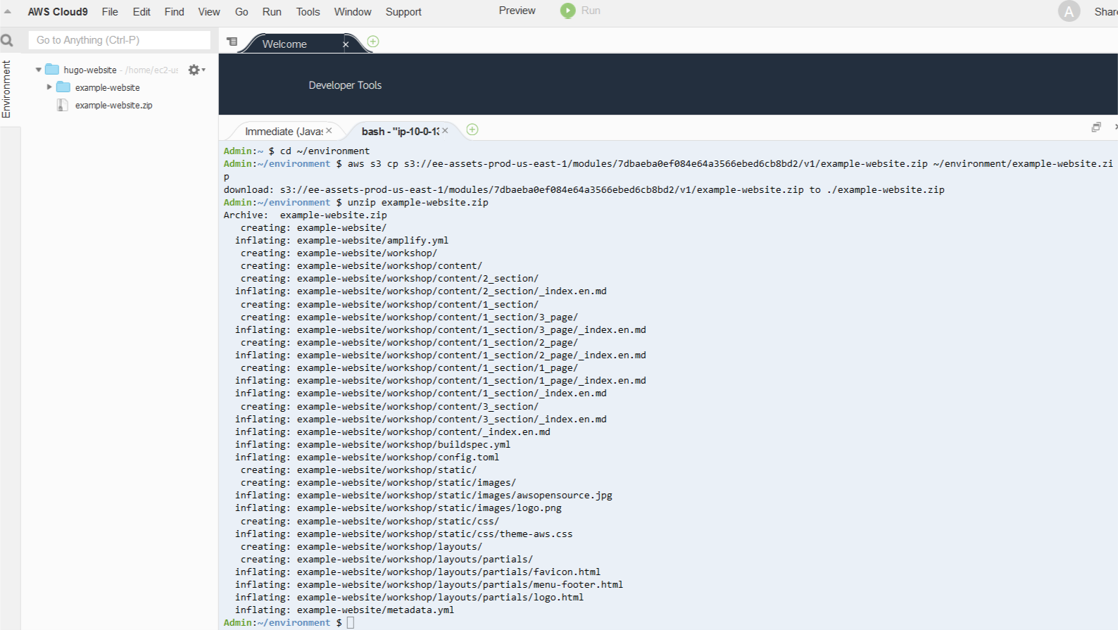
2. Enter the following code to download an existing example website stored as a .zip file, extract it, and commit the contents into CodeCommit from your AWS Cloud9 IDE:

cd ~/environment
aws s3 cp s3://ee-assets-prod-us-east-1/modules/3c5ba9cb6ff44465b96993d210f67147/v1/example-website.zip ~/environment/example-website.zip
unzip example-website.zip
rm example-website.zip

The following screenshot shows your output.

example website copy commands


Next, we run commands to create a directory to host your website and copy files into place from the example website to get started. We then create a new default branch called main (formerly referred to as the master branch), local to our AWS Cloud9 instance. We then copy files into place from the example website. After adding and committing them locally, we push all our changes to the remote Amazon Codecommit repository.

3. Enter the following code:

mkdir ~/environment/amplify-website/
cd ~/environment/amplify-website/
git init
git remote add origin codecommit::us-east-1://amplify-website
git remote -v
git checkout -b main
cp -rp ~/environment/example-website/* ~/environment/amplify-website/
git add *
git commit -am "first commit"
git push -u origin main

Deployment and hosting is achieved by using Amplify Console, a static web hosting service that accelerates your application release cycle by providing a simple CI/CD workflow for building and deploying static web applications.

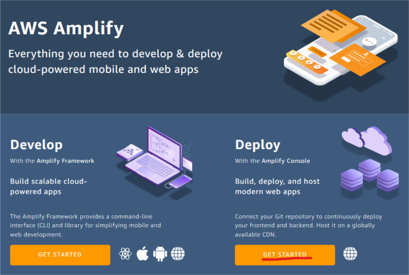
4. On the Amplify console, under Deploy, choose Get Started.

Amplify banner

5. On the Get started with the Amplify Console page, select AWS CodeCommit as your source code repository.

6. Choose Continue.

Amplify get started page

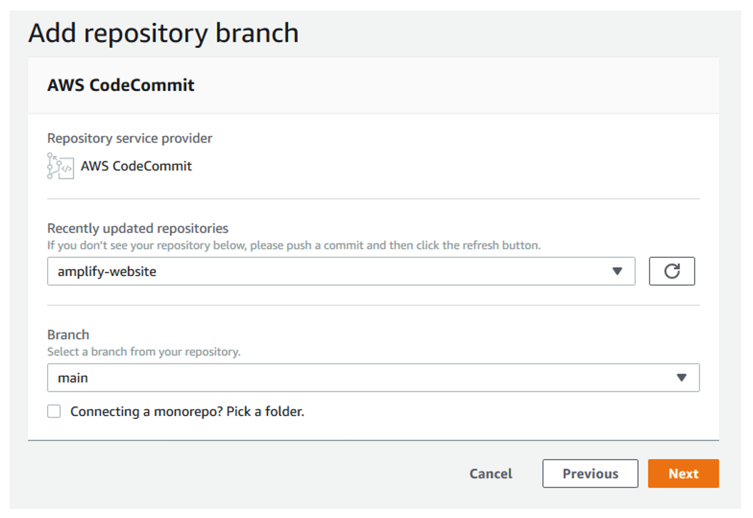
7. On the Add repository branch page, for Recently updated repositories, choose your repository.

8. For Branch, choose main.

9. Choose Next.

add branch

On the Configure build settings page, Amplify automatically uses the amplify.yml file for build settings for your deployment. You committed this into your source code repository in the previous step. The amplify.yml file is detected from the root of your website directory structure.

10. Choose Next.

Amplify configure build settings

11. On the review page, choose Save and deploy.

Amplify builds and deploys your Amplify website within minutes, and shows you its progress. When deployment is complete, you can access the website to see the sample content.

amplify website

The following screenshot shows your example website.

sample website


Promoting changes to the website

We can now update the line of text in the home page and commit and publish this change.

1. Return to the browser with your AWS Cloud9 IDE and place your cursor in the lower terminal pane of the IDE.

2. On the navigation pane, choose the file ~/environment/amplify-website/workshop/content/_index.en.md.

The contents of the file open under a new tab in the upper pane.

3. Change the string First Line of Text to First Update to Website.

content change

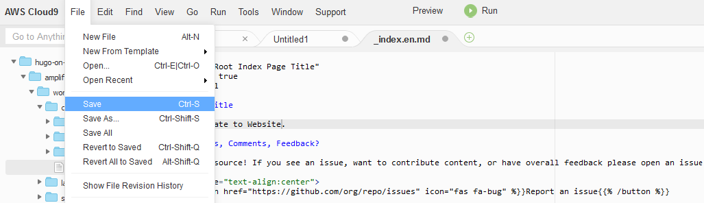
4. From the File menu, choose Save to save the changes you have made to the _index.en.md file.

save content changes

5. Commit the changes and push to CodeCommit by running the following command in the lower terminal pane in AWS Cloud9:

git add *; git commit -am "homepage update"; git push origin main

The output in your AWS Cloud9 terminal should appear similar to the following screenshot.

commit output

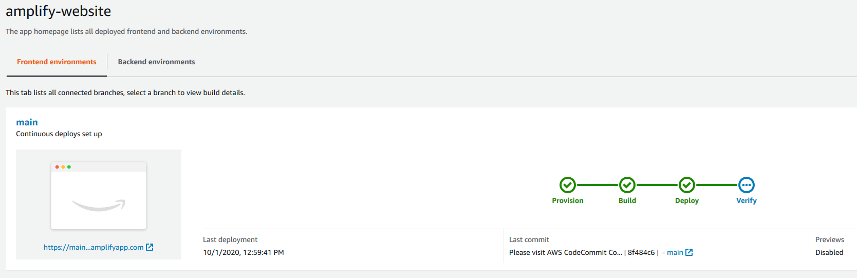
6. Return to the Amplify Console and observe how the committed change in CodeCommit is automatically detected. Amplify runs deployment steps to push your changes to the website.

amplify deploy changes

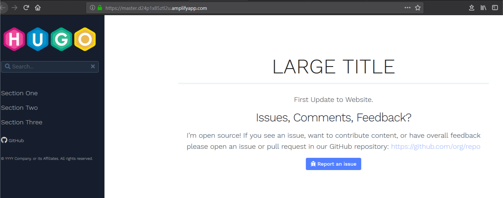
7. Access the URL of your website after this update is complete to verify that the first line of text on your home page has changed.

updated website

You can repeat this process to make source-code controlled, automated changes to your website.

Adding a custom domain

Adding a custom domain to your Amplify configuration makes it easier for clients to access your content. You can register new domains using Amazon Route 53 or, if you have an existing domain registered outside of AWS, you can integrate it with Route 53 and Amplify. For our use case, the domain www.hugoonamplify.com is a registered a domain name using a third-party registrar (NameCheap). You can manage DNS configurations for domains registered outside of AWS using Route 53.

Start by configuring a public hosted zone in Route 53.

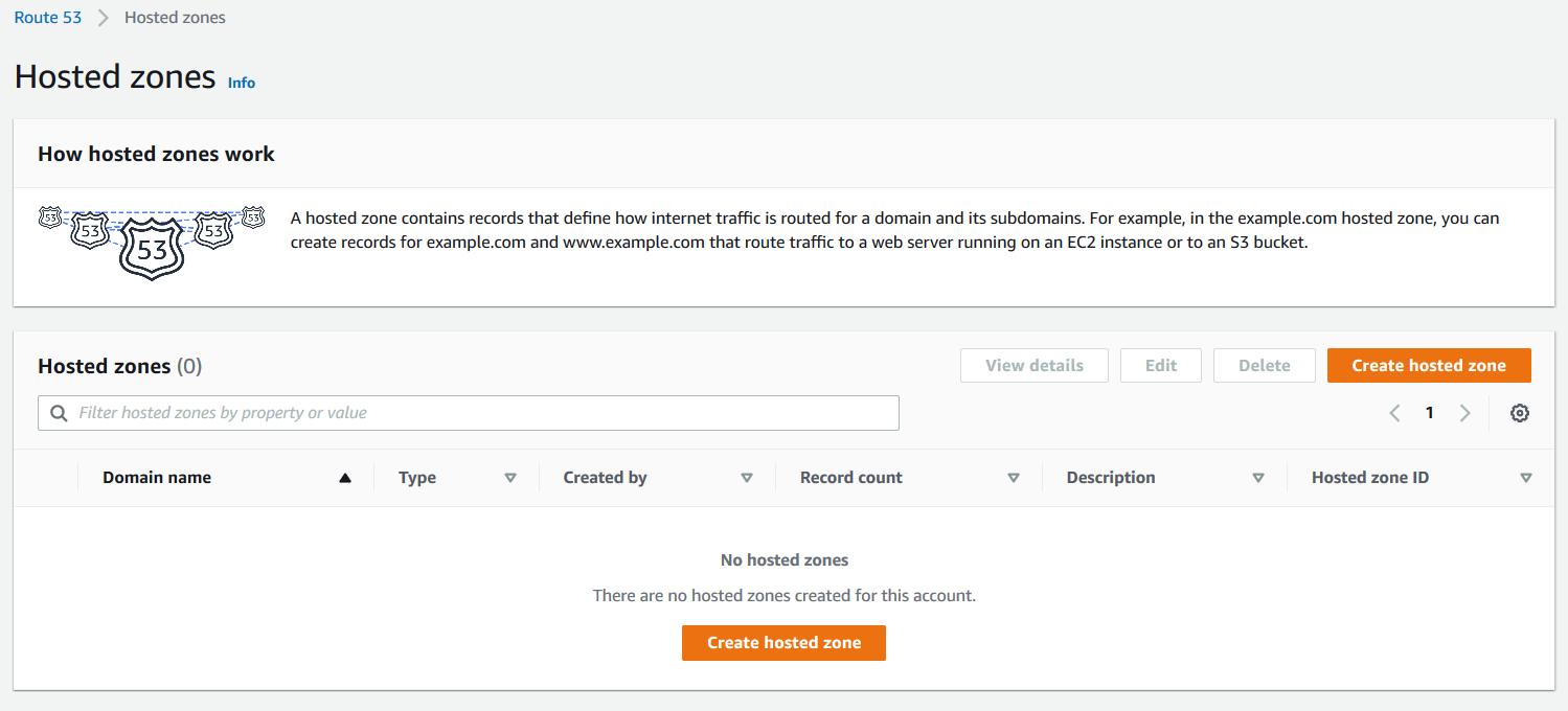
1. On the Route 53 console, choose Hosted zones.

2. Choose Create hosted zone.

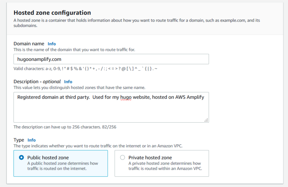
hosted zones

3. For Domain name, enter hugoonamplify.com.

4. For Description, enter an appropriate description.

5. For Type, select Public hosted zone.

hosted zones configuration

6. Choose Create hosted zone.

7. Save the addresses of the name servers that respond to client DNS lookup requests for the custom domain.

create hosted zone

8. In a separate browser, access the console of your DNS registrar.

9. Configure a custom DNS name servers setting on the console of the third-party domain name registrar.

This configuration specifies the Route 53 assigned name servers as authoritative DNS for our custom domain. For this use case, propagation of this change may take up to 48 hours.

namecheap console

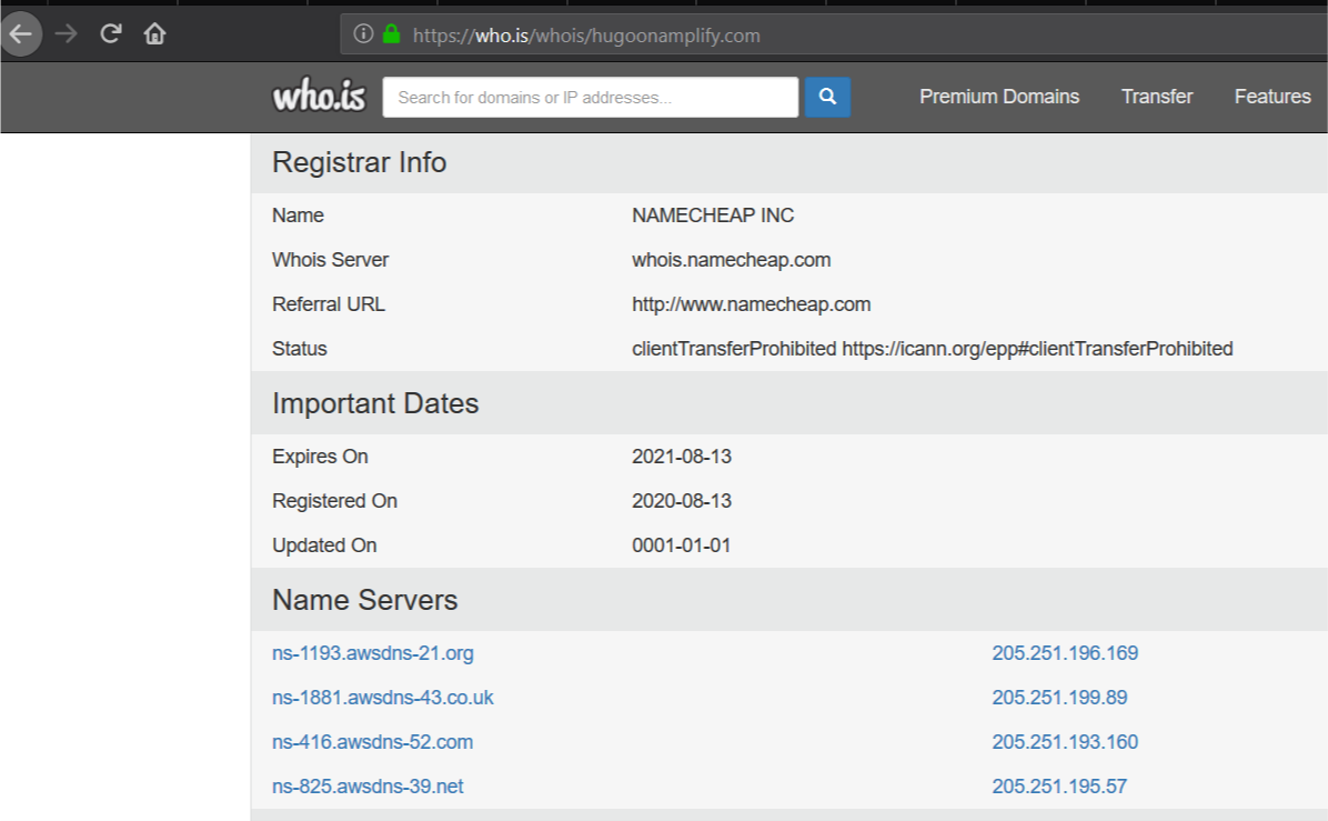
10. Use https://who.is to verify that the AWS name servers are listed correctly for your custom domain to internet clients.

whois lookup

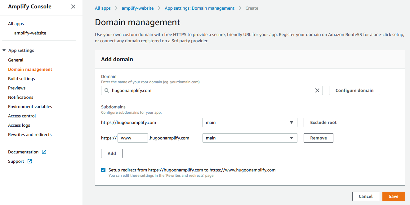
You can now set up your custom domain in Amplify. Amplify helps you configure DNS and set up SSL for your desired custom domain.

domain management

11. On the Amplify Console, under App settings, choose Domain management.

12. Choose Add domain.

13. For Domain, enter your custom domain name (hugoonamplify.com).

14. Choose Configure domain.

15. For Subdomain, I only want to set up www and choose to exclude the root of my custom domain.

16. Choose Save.

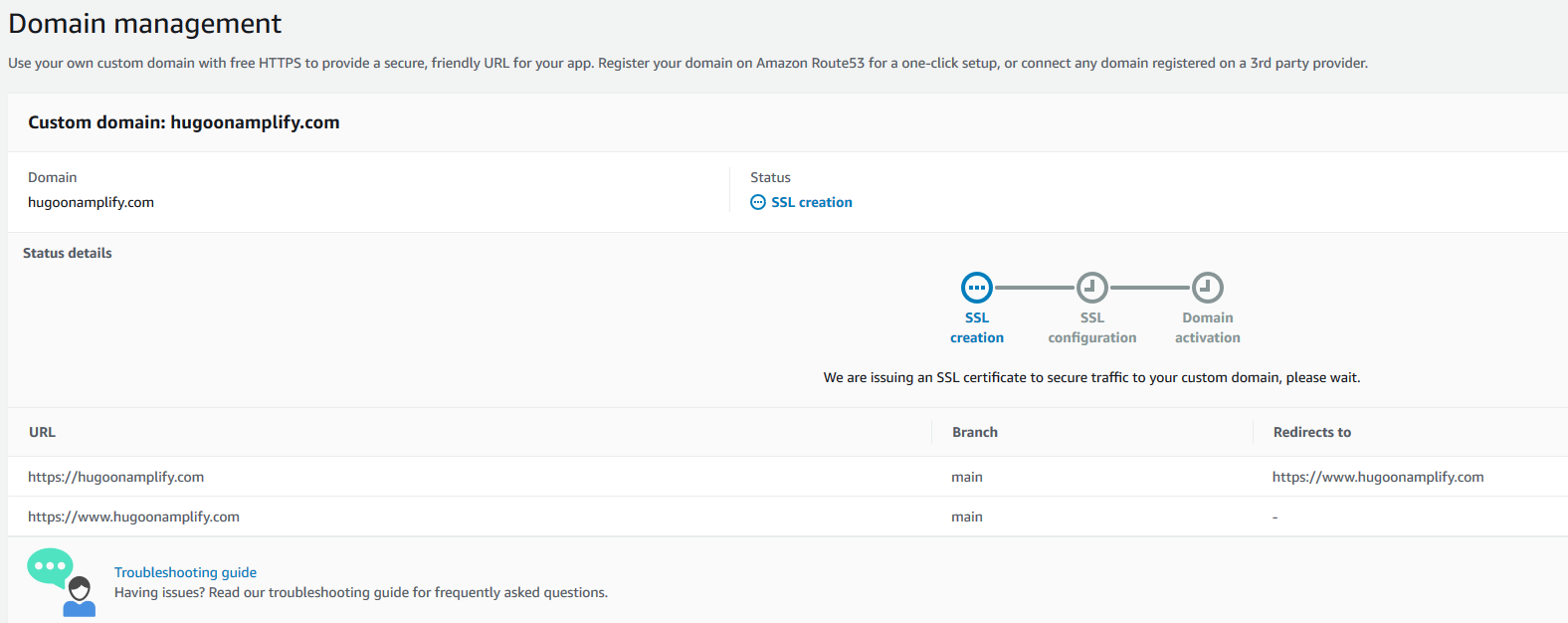
Amplify begins the process of creating the SSL certificates. Amplify sends a notification that it’s issuing an SSL certificate to secure traffic to the custom domain.

ssl domain management

After a few moments, it proceeds to SSL configuration and indicates that ownership of domain is in progress.

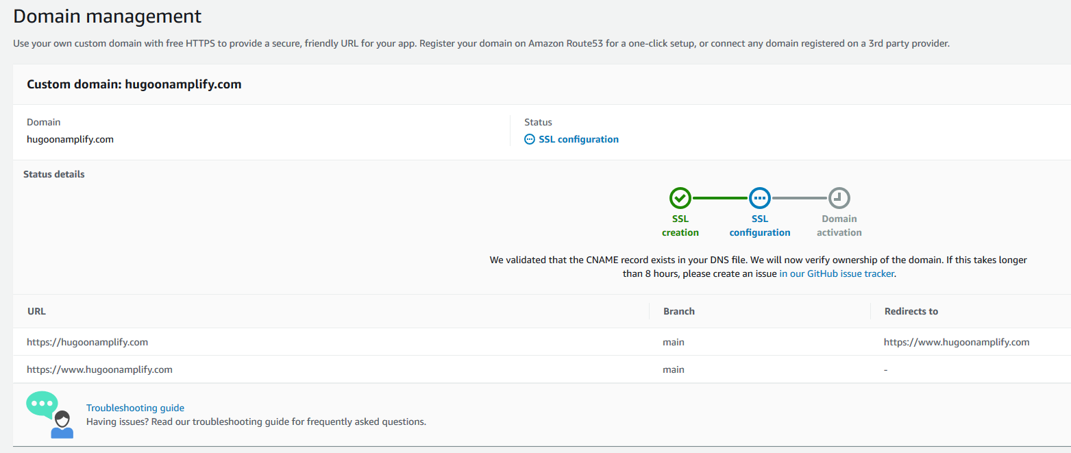
ssl domain management configuration

Amplify verifies domain ownership by creating a sample CNAME record in your hosted zone file. When ownership is verified, the domain is propagated onto an Amazon CloudFront distribution managed by the Amplify service, and domain activation is complete.

ssl domain management configured

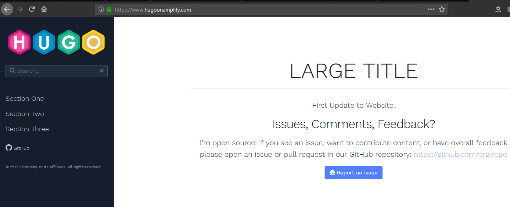
Clients can now access the website using the custom domain name www.hugoonaplify.com.

access website via custom domain


Establishing a subdomain for development

You can create a development website in Amplify that is aligned to a development code branch in CodeCommit that enables testing changes prior to production release.

1. Access the AWS Cloud9 IDE and use the terminal to enter the following commands to create a development branch and push changes to CodeCommit using the current content from the main branch with a single content change:

git checkout -b development
git branch
git remote -v
git add *; git commit -am "first development commit";
git push -u origin development

2. Open and edit the file ~/environment/amplify-website/workshop/content/_index.en.md and change the string Update to Website to something else.

Alternatively, run the following Unix sed command from the terminal in AWS Cloud9 to make that content change:

sed -i 's/Update to Website/Update to Development/g' ~/environment/amplify-website/workshop/content/_index.en.md

3. Commit and push your change with the following code:

git add *; git commit -am "second development commit"; git push -u origin development

You now configure a subdomain in Amplify to allow developers to review changes.

4. Return to the amplify-website app.

5. Choose Connect branch.

connect branch

6. For Branch, choose the development branch you created and committed code into.

7. Choose Next.

add development branch

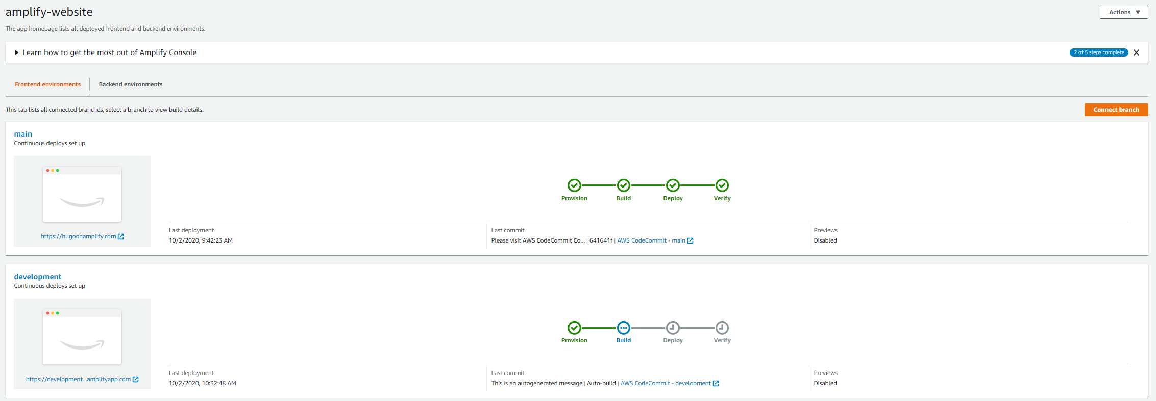
Amplify builds a second website based on the contents of the development branch. You can see the instance of your website matched to the development code branch on Amplify Console.

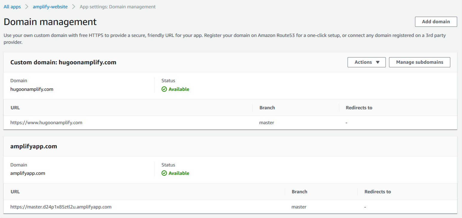
amplify two branches

8. Access the domain management menu item in your Amplify application to add a friendly subdomain.

9. Edit the domain and add a subdomain item with a name of your choice (for example, dev).

10. Associate it to the development branch containing the committed code and content changes.

11. Choose Add.

add dev domain

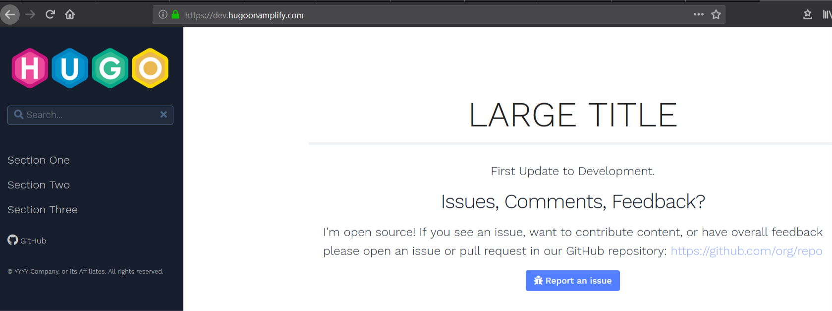
You can access the subdomain to verify the changes.

verify domain

Controlling access to development

You may wish to restrict access to new content as it’s deployed into the development website.

1. On Amplify Console, choose your application.

2. Choose Access control.

3. Under Access control settings, choose your preferred settings.

You have the option to restrict access globally or on a branch-by-branch basis. For this use case, we create a simple password protection for a user named developer on the development branch and site.

access control settings


Cleaning up

Unless you plan to keep the website you have constructed, you can quickly clean up provisioned assets and avoid any unnecessary costs.

1. On Amplify Console, select the app you created.

2. From the Actions drop-down menu, choose Delete app.

3. In the pop-up window, confirm the deletion.

4. On the CodeCommit dashboard, select the repository you created.

5. Choose Delete.

6. In the pop-up window, confirm the deletion.

7. On the AWS Cloud9 dashboard, select the IDE you created.

8. Choose Delete.

9. In the pop-up window, confirm the deletion.


Conclusion

Hugo is a powerful tool that enables accelerated delivery of content in a variety of formats including image portfolios, online resume presentation, blogging, and technical documentation. Amplify Console provides a convenient, easy-to-use, static web hosting service that can greatly accelerate delivery of static content.

When combining Hugo with Amplify Console, you can rapidly deploy websites in minutes with features such as friendly URLS, environments matched to code branches, and encryption (SSL). Visit gohugo.io to find out more about Hugo. For more information about how Amplify Console can help you rapidly deploy Hugo and other modern web applications, see the AWS Amplify Console User Guide.

Nigel Harris

Nigel Harris

Nigel Harris is an Enterprise Solutions Architect at Amazon Web Services. He works with AWS customers to provide guidance and technical assistance on AWS architectures.

How to configure an LDAPS endpoint for Simple AD

Post Syndicated from Marco Sommella original https://aws.amazon.com/blogs/security/how-to-configure-ldaps-endpoint-for-simple-ad/

In this blog post, we show you how to configure an LDAPS (LDAP over SSL or TLS) encrypted endpoint for Simple AD so that you can extend Simple AD over untrusted networks. Our solution uses Network Load Balancer (NLB) as SSL/TLS termination. The data is then decrypted and sent to Simple AD. Network Load Balancer offers integrated certificate management, SSL/TLS termination, and the ability to use a scalable Amazon Elastic Compute Cloud (Amazon EC2) backend to process decrypted traffic. Network Load Balancer also tightly integrates with Amazon Route 53, enabling you to use a custom domain for the LDAPS endpoint. To simplify testing and deployment, we have provided an AWS CloudFormation template to provision the network load balancer (NLB).

Simple AD, which is powered by Samba 4, supports basic Active Directory (AD) authentication features such as users, groups, and the ability to join domains. Simple AD also includes an integrated Lightweight Directory Access Protocol (LDAP) server. LDAP is a standard application protocol for accessing and managing directory information. You can use the BIND operation from Simple AD to authenticate LDAP client sessions. This makes LDAP a common choice for centralized authentication and authorization for services such as Secure Shell (SSH), client-based virtual private networks (VPNs), and many other applications. Authentication, the process of confirming the identity of a principal, typically involves the transmission of highly sensitive information such as user names and passwords. To protect this information in transit over untrusted networks, companies often require encryption as part of their information security strategy.

This post assumes that you understand concepts such as Amazon Virtual Private Cloud (Amazon VPC) and its components, including subnets, routing, internet and network address translation (NAT) gateways, DNS, and security groups. If needed, you should familiarize yourself with these concepts and review the solution overview and prerequisites in the next section before proceeding with the deployment.

Note: This solution is intended for use by clients who require only an LDAPS endpoint. If your requirements extend beyond this, you should consider accessing the Simple AD servers directly or by using AWS Directory Service for Microsoft AD.

Solution overview

The following description explains the Simple AD LDAPS environment. The AWS CloudFormation template creates the network-load-balancer object.

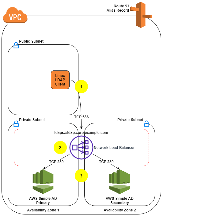
  1. The LDAP client sends an LDAPS request to the NLB on TCP port 636.
  2. The NLB terminates the SSL/TLS session and decrypts the traffic using a certificate. The NLB sends the decrypted LDAP traffic to Simple AD on TCP port 389.
  3. The Simple AD servers send an LDAP response to the NLB. The NLB encrypts the response and sends it to the client.

The following diagram illustrates how the solution works and shows the prerequisites (listed in the following section).

Figure 1: LDAPS with Simple AD Architecture

Figure 1: LDAPS with Simple AD Architecture

Note: Amazon VPC prevents third parties from intercepting traffic within the VPC. Because of this, the VPC protects the decrypted traffic between the NLB and Simple AD. The NLB encryption provides an additional layer of security for client connections and protects traffic coming from hosts outside the VPC.

Prerequisites

  1. Our approach requires an Amazon VPC with one public and two private subnets. If you don’t have an Amazon VPC that meets that requirement, use the following instructions to set up a sample environment:
    1. Identify an AWS Region that supports Simple AD and network load balancing.
    2. Identify two Availability Zones in that Region to use with Simple AD. The Availability Zones are needed as parameters in the AWS CloudFormation template used later in this process.
    3. Create or choose an Amazon VPC in the region you chose.
    4. Enable DNS support within your VPC so you can use Route 53 to resolve the LDAPS endpoint.
    5. Create two private subnets, one per Availability Zone. The Simple AD servers use the subnets that you create.
    6. Create a public subnet in the same VPC.
    7. The LDAP service requires a DNS domain that resolves within your VPC and from your LDAP clients. If you don’t have an existing DNS domain, create a private hosted zone and associate it with your VPC. To avoid encryption protocol errors, you must ensure that the DNS domain name is consistent across your Route 53 zone and in the SSL/TLS certificate.
  2. Make sure you’ve completed the Simple AD prerequisites.
  3. You can use a certificate issued by your preferred certificate authority or a certificate issued by AWS Certificate Manager (ACM). If you don’t have a certificate authority, you can create a self-signed certificate by following the instructions in section 2 (Create a certificate).

Note: To prevent unauthorized direct connections to your Simple AD servers, you can modify the Simple AD security group on port 389 to block traffic from locations outside of the Simple AD VPC. You can find the security group in the Amazon EC2 console by creating a search filter for your Simple AD directory ID. It is also important to allow the Simple AD servers to communicate with each other as shown on Simple AD Prerequisites.

Solution deployment

This solution includes 5 main parts:

  1. Create a Simple AD directory.
  2. (Optional) Create a SSL/TLS certificate, if you don’t have already have one.
  3. Create the NLB by using the supplied AWS CloudFormation template.
  4. Create a Route 53 record.
  5. Test LDAPS access using an Amazon Linux 2 client.

1. Create a Simple AD directory

With the prerequisites completed, your first step is to create a Simple AD directory in your private VPC subnets.

To create a Simple AD directory:

  1. In the Directory Service console navigation pane, choose Directories and then choose Set up directory.
  2. Choose Simple AD.

    Figure 2: Select directory type

    Figure 2: Select directory type

  3. Provide the following information:
    1. Directory Size: The size of the directory. The options are Small or Large. Which you should choose depends on the anticipated size of your directory.
    2. Directory DNS: The fully qualified domain name (FQDN) of the directory, such as corp.example.com.

      Note: You will need the directory FQDN when you test your solution.

    3. NetBIOS name: The short name for the directory, such as corp.
    4. Administrator password: The password for the directory administrator. The directory creation process creates an administrator account with the user name Administrator and this password. Don’t lose this password, because it can’t be recovered. You also need this password for testing LDAPS access in a later step.
    5. Description: An optional description for the directory.
    Figure 3: Directory information

    Figure 3: Directory information

  4. Select the VPC and subnets, and then choose Next:
    • VPC: Use the dropdown list to select the VPC to install the directory in.
    • Subnets: Use the dropdown lists to select two private subnets for the directory servers. The two subnets must be in different Availability Zones. Make a note of the VPC and subnet IDs to use as input parameters for the AWS CloudFormation template. In the following example, the subnets are in the us-east-1a and us-east-1c Availability Zones.
    Figure 4: Choose VPC and subnets

    Figure 4: Choose VPC and subnets

  5. Review the directory information and make any necessary changes. When the information is correct, choose Create directory.

    Figure 5: Review and create the directory

    Figure 5: Review and create the directory

  6. It takes several minutes to create the directory. From the AWS Directory Service console, refresh the screen periodically and wait until the directory Status value changes to Active before continuing.
  7. When the status has changed to Active, choose your Simple AD directory and note the two IP addresses in the DNS address section. You will enter them in a later step when you run the AWS CloudFormation template.

Note: How to administer your Simple AD implementation is out of scope for this post. See the documentation to add users, groups, or instances to your directory. Also see the previous blog post, How to Manage Identities in Simple AD Directories.

2. Add a certificate

Now that you have a Simple AD directory, you need a SSL/TLS certificate. The certificate will be used with the NLB to secure the LDAPS endpoint. You then import the certificate into ACM, which is integrated with the NLB.

As mentioned earlier, you can use a certificate issued by your preferred certificate authority or a certificate issued by AWS Certificate Manager (ACM).

(Optional) Create a self-signed certificate

If you don’t already have a certificate authority, you can use the following instructions to generate a self-signed certificate using OpenSSL.

Note: OpenSSL is a standard, open source library that supports a wide range of cryptographic functions, including the creation and signing of x509 certificates.

Use the command line interface to create a certificate:

  1. You must have a system with OpenSSL installed to complete this step. If you don’t have OpenSSL, you can install it on Amazon Linux by running the command sudo yum install openssl. If you don’t have access to an Amazon Linux instance you can create one with SSH access enabled to proceed with this step. Use the command line to run the command openssl version to see if you already have OpenSSL installed.
    [ec2-user@ip-10-21-32-162 ~]$ openssl version
    OpenSSL 1.0.1k-fips 8 Jan 2015
    

  2. Create a private key using the openssl genrsa command.
    [ec2-user@ip-10-21-32-162 tmp]$ openssl genrsa 2048 > privatekey.pem
    Generating RSA private key, 2048 bit long modulus
    ......................................................................................................................................................................+++
    ..........................+++
    e is 65537 (0x10001)
    

  3. Generate a certificate signing request (CSR) using the openssl req command. Provide the requested information for each field. The Common Name is the FQDN for your LDAPS endpoint (for example, ldap.corp.example.com). The Common Name must use the domain name you will later register in Route 53. You will encounter certificate errors if the names do not match.
    [ec2-user@ip-10-21-32-162 tmp]$ openssl req -new -key privatekey.pem -out server.csr
    You are about to be asked to enter information that will be incorporated into your certificate request.
    

  4. Use the openssl x509 command to sign the certificate. The following example uses the private key from the previous step (privatekey.pem) and the signing request (server.csr) to create a public certificate named server.crt that is valid for 365 days. This certificate must be updated within 365 days to avoid disruption of LDAPS functionality.
    [ec2-user@ip-10-21-32-162 tmp]$ openssl x509 -req -sha256 -days 365 -in server.csr -signkey privatekey.pem -out server.crt
    Signature ok
    subject=/C=XX/L=Default City/O=Default Company Ltd/CN=ldap.corp.example.com
    Getting Private key
    

  5. You should see three files: privatekey.pem, server.crt, and server.csr.
    [ec2-user@ip-10-21-32-162 tmp]$ ls
    privatekey.pem server.crt server.csr
    

  6. Restrict access to the private key.
    [ec2-user@ip-10-21-32-162 tmp]$ chmod 600 privatekey.pem
    

Note: Keep the private key and public certificate to use later. You can discard the signing request, because you are using a self-signed certificate and not using a certificate authority. Always store the private key in a secure location, and avoid adding it to your source code.

Import a certificate

For this step, you can either use a certificate obtained from a certificate authority, or a self-signed certificate that you created using the optional procedure above.

  1. In the ACM console, choose Import a certificate.
  2. Using a Linux text editor, paste the contents of your certificate file (called server.crt if you followed the procedure above) file in the Certificate body box.
  3. Using a Linux text editor, paste the contents of your privatekey.pem file in the Certificate private key box. (For a self-signed certificate, you can leave the Certificate chain box blank.)
  4. Choose Review and import. Confirm the information and choose Import.
  5. Take note of the Amazon Resource Name (ARN) of the imported certificate.

3. Create the NLB by using the supplied AWS CloudFormation template

Now that you have a Simple AD directory and SSL/TLS certificate, you’re ready to use the AWS CloudFormation template to create the NLB.

Create the NLB:

  1. Load the AWS CloudFormation template to deploy an internal NLB. After you load the template, provide the input parameters from the following table:

    Input parameter Input parameter description
    VPCId The target VPC for this solution. Must be the VPC where you deployed Simple AD and available in your Simple AD directory details page.
    SubnetId1 The Simple AD primary subnet. This information is available in your Simple AD directory details page.
    SubnetId2 The Simple AD secondary subnet. This information is available in your Simple AD directory details page.
    SimpleADPriIP The primary Simple AD Server IP. This information is available in your Simple AD directory details page.
    SimpleADSecIP The secondary Simple AD Server IP. This information is available in your Simple AD directory details page.
    LDAPSCertificateARN The Amazon Resource Name (ARN) for the SSL certificate. This information is available in the ACM console.
  2. Enter the input parameters and choose Next.
  3. On the Options page, accept the defaults and choose Next.
  4. On the Review page, confirm the details and choose Create. The stack will be created in approximately 5 minutes.
  5. Wait until the AWS Cloud formation stack status is CREATE_COMPLETE before starting the next procedure, Create a Route 53 record.
  6. Go to Outputs and note the FQDN of your new NLB. The FQDN is in the output variable named LDAPSURL.

    Note: You can find the parameters of your Simple AD on the directory details page by choosing your Simple AD in the Directory Service console.

4. Create a Route 53 record

The next step is to create a Route 53 record in your private hosted zone so that clients can resolve your LDAPS endpoint.

Note: Don’t start this procedure until the AWS CloudFormation stack status is CREATE_COMPLETE.

Create a Route 53 record:

  1. If you don’t have an existing DNS domain for use with LDAP, create a private hosted zone and associate it with your VPC. The hosted zone name should be consistent with your Simple AD (for example, corp.example.com).
  2. When the AWS CloudFormation stack is in CREATE_COMPLETE status, locate the value of the LDAPSURL on the Outputs tab of the stack. Copy this value for use in the next step.
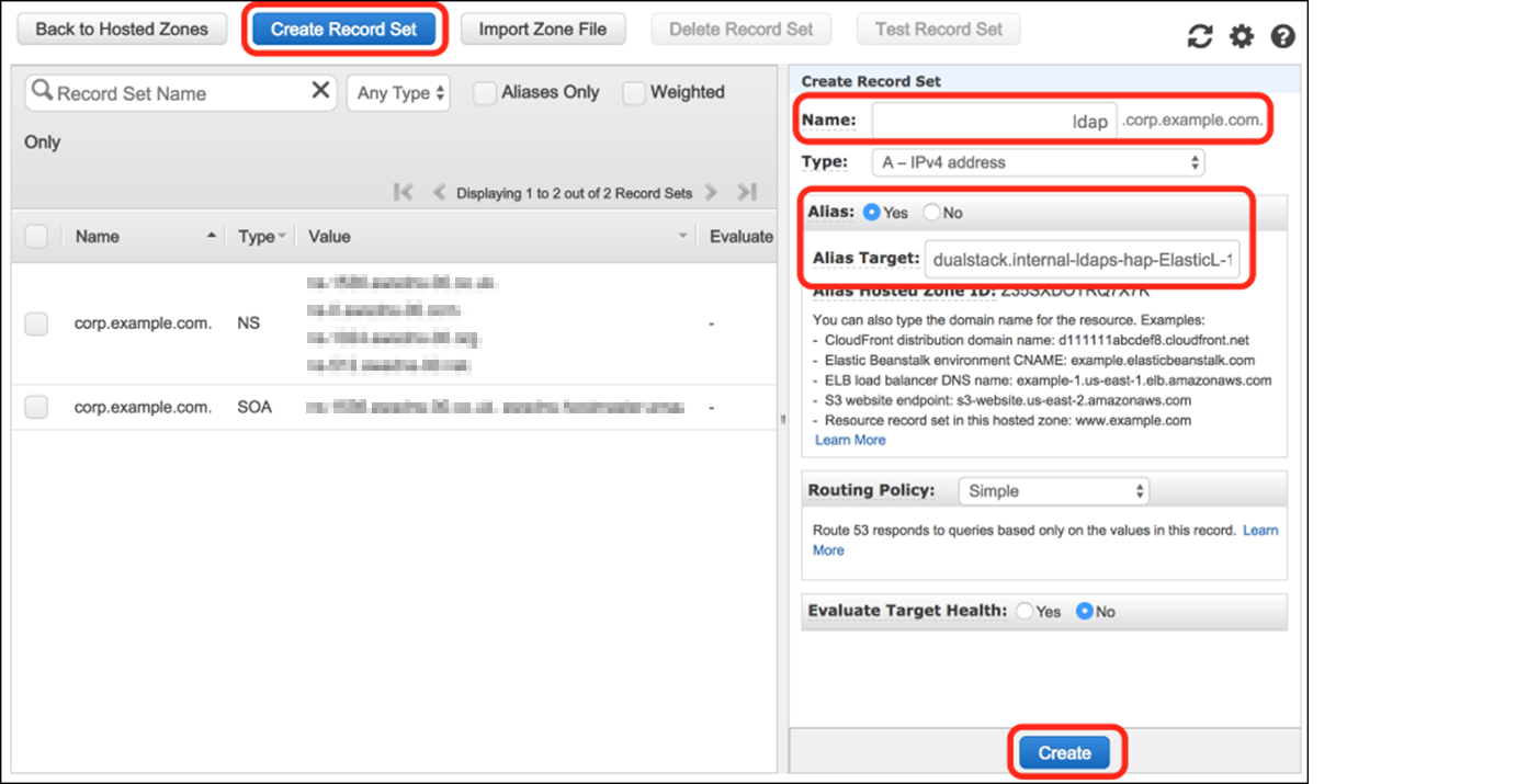
  3. On the Route 53 console, choose Hosted Zones and then choose the zone you used for the Common Name value for your self-signed certificate. Choose Create Record Set and enter the following information:
    1. Name: A short name for the record set (remember that the FQDN has to match the Common Name of your certificate).
    2. Type: Leave as A – IPv4 address.
    3. Alias: Select Yes.
    4. Alias Target: Paste the value of the LDAPSURL from the Outputs tab of the stack.
  4. Leave the defaults for Routing Policy and Evaluate Target Health, and choose Create.
Figure 6: Create a Route 53 record

Figure 6: Create a Route 53 record

5. Test LDAPS access using an Amazon Linux 2 client

At this point, you’re ready to test your LDAPS endpoint from an Amazon Linux client.

Test LDAPS access:

  1. Create an Amazon Linux 2 instance with SSH access enabled to test the solution. Launch the instance on one of the public subnets in your VPC. Make sure the IP assigned to the instance is in the trusted IP range you specified in the security group associated with the Simple AD.
  2. Use SSH to sign in to the instance and complete the following steps to verify access.
    1. Install the openldap-clients package and any required dependencies:
      sudo yum install -y openldap-clients.
      

    2. Add the server.crt file to the /etc/openldap/certs/ directory so that the LDAPS client will trust your SSL/TLS certificate. You can download the file directly from the NLB the certificate and save it in the proper format, or copy the file using Secure Copy or create it using a text editor:
      openssl s_client -connect <LDAPSURL>:636 -showcerts </dev/null 2>/dev/null | openssl x509 -outform PEM > server.crt 
      

      Replace <LDAPSURL> with the FQDN of your NLB, the address can be found in the Outputs section of the stack created in CloudFormation.

    3. Edit the /etc/openldap/ldap.conf file to define the environment variables:
      • BASE: The Simple AD directory name.
      • URI: Your DNS alias.
      • TLS_CACERT: The path to your public certificate.
      • TLSCACertificateFile: The path to your self-signed certificate authority. If you used the instructions in section 2 (Create a certificate) to create a certificate, the path will be /etc/ssl/certs/ca-bundle.crt.

      Here’s an example of the file:

      BASE dc=corp,dc=example,dc=com
      URI ldaps://ldap.corp.example.com
      TLS_CACERT /etc/openldap/certs/server.crt
      TLSCACertificateFile /etc/ssl/certs/ca-bundle.crt
      

  3. To test the solution, query the directory through the LDAPS endpoint, as shown in the following command. Replace corp.example.com with your domain name and use the Administrator password that you configured in step 3 of section 1 (Create a Simple AD directory).
    $ ldapsearch -D "[email protected]" -W sAMAccountName=Administrator
    

  4. The response will include the directory information in LDAP Data Interchange Format (LDIF) for the administrator distinguished name (DN) from your Simple AD LDAP server.
    # extended LDIF
    #
    # LDAPv3
    # base <dc=corp,dc=example,dc=com> (default) with scope subtree
    # filter: sAMAccountName=Administrator
    # requesting: ALL
    #
    
    # Administrator, Users, corp.example.com
    dn: CN=Administrator,CN=Users,DC=corp,DC=example,DC=com
    objectClass: top
    objectClass: person
    objectClass: organizationalPerson
    objectClass: user
    description: Built-in account for administering the computer/domain
    instanceType: 4
    whenCreated: 20170721123204.0Z
    uSNCreated: 3223
    name: Administrator
    objectGUID:: l3h0HIiKO0a/ShL4yVK/vw==
    userAccountControl: 512
    …
    

You can now use the LDAPS endpoint for directory operations and authentication within your environment. Here are a few resources to learn more about how to interact with an LDAPS endpoint:

Troubleshooting

If the ldapsearch command returns something like the following error, there are a few things you can do to help identify issues.

ldap_sasl_bind(SIMPLE): Can't contact LDAP server (-1)
  1. You might be able to obtain additional error details by adding the -d1 debug flag to the ldapsearch command.
    $ ldapsearch -D "[email protected]" -W sAMAccountName=Administrator –d1
    

  2. Verify that the parameters in ldap.conf match your configured LDAPS URI endpoint and that all parameters can be resolved by DNS. You can use the following dig command, substituting your configured endpoint DNS name.
    $ dig ldap.corp.example.com
    

  3. Confirm that the client instance you’re connecting from is in the trusted IP range you specified in the security associated with your Simple AD directory.
  4. Confirm that the path to your public SSL/TLS certificate in ldap.conf as TLS_CAERT is correct. You configured this as part of step 2 in section 5 (Test LDAPS access using an Amazon Linux 2 client). You can check your SSL/TLS connection with the following command, replacing ldap.corp.example.com with the DNS name of your endpoint.
    $ echo -n | openssl s_client -connect ldap.corp.example.com:636
    

  5. Verify that the status of your Simple AD IPs is Healthy in the Amazon EC2 console.
    1. Open the EC2 console and choose Load Balancing and then Target Groups in the navigation pane.
    2. Choose your LDAPS target and then choose Targets.

Conclusion

You can use NLB to provide an LDAPS endpoint for Simple AD and transport sensitive authentication information over untrusted networks. You can explore using LDAPS to authenticate SSH users or integrate with other software solutions that support LDAP authentication. The AWS CloudFormation template for this solution is available on GitHub.

If you have comments about this post, submit them in the Comments section below. If you have questions about or issues implementing this solution, start a new thread on the AWS Directory Service forum or contact AWS Support.

Want more AWS Security how-to content, news, and feature announcements? Follow us on Twitter.

Marco Somella

Marco Sommella

Marco is a Cloud Support Engineer II in the Windows Team based in Dublin. He is a Subject Matter Expert on Directory Service and EC2 Windows. Marco has over 10 years experience as a Windows and Linux system administrator and is passionate about automation coding. He is actively involved in AWS Systems Manager public Automations released by AWS Support and AWS EC2.

Cameron Worrell

Cameron Worrell

Cameron is a Solutions Architect with a passion for security and enterprise transformation. He joined AWS in 2015.

Log your VPC DNS queries with Route 53 Resolver Query Logs

Post Syndicated from Martin Beeby original https://aws.amazon.com/blogs/aws/log-your-vpc-dns-queries-with-route-53-resolver-query-logs/

The Amazon Route 53 team has just launched a new feature called Route 53 Resolver Query Logs, which will let you log all DNS queries made by resources within your Amazon Virtual Private Cloud. Whether it’s an Amazon Elastic Compute Cloud (EC2) instance, an AWS Lambda function, or a container, if it lives in your Virtual Private Cloud and makes a DNS query, then this feature will log it; you are then able to explore and better understand how your applications are operating.

Our customers explained to us that DNS query logs were important to them. Some wanted the logs so that they could be compliant with regulations, others wished to monitor DNS querying behavior, so they could spot security threats. Others simply wanted to troubleshoot application issues that were related to DNS. The team listened to our customers and have developed what I have found to be an elegant and easy to use solution.

From knowing very little about the Route 53 Resolver, I was able to configure query logging and have it working with barely a second glance at the documentation; which I assure you is a testament to the intuitiveness of the feature rather than me having any significant experience with Route 53 or DNS query logging.

You can choose to have the DNS query logs sent to one of three AWS services: Amazon CloudWatch Logs, Amazon Simple Storage Service (S3), and Amazon Kinesis Data Firehose. The target service you choose will depend mainly on what you want to do with the data. If you have compliance mandates (For example, Australia’s Information Security Registered Assessors Program), then maybe storing the logs in Amazon Simple Storage Service (S3) is a good option. If you have plans to monitor and analyze DNS queries in real-time or you integrate your logs with a 3rd party data analysis tool like Kibana or a SEIM tool like Splunk, than perhaps Amazon Kinesis Data Firehose is the option for you. For those of you who want an easy way to search, query, monitor metrics, or raise alarms, then Amazon CloudWatch Logs is a great choice, and this is what I will show in the following demo.

Over in the Route 53 Console, near the Resolver menu section, I see a new item called Query logging. Clicking on this takes me to a screen where I can configure the logging.

The dashboard shows the current configurations that are setup. I click Configure query logging to get started.

The console asks me to fill out some necessary information, such as a friendly name; I’ve named mine demoNewsBlog.

I am now prompted to select the destination where I would like my logs to be sent. I choose the CloudWatch Logs log group and select the option to Create log group. I give my new log group the name /aws/route/demothebeebsnet.

Next, I need to select what VPC I would like to log queries for. Any resource that sits inside the VPCs I choose here will have their DNS queries logged. You are also able to add tags to this configuration. I am in the habit of tagging anything that I use as part of a demo with the tag demo. This is so I can easily distinguish between demo resources and live resources in my account.

Finally, I press the Configure query logging button, and the configuration is saved. Within a few moments, the service has successfully enabled the query logging in my VPC.

After a few minutes, I log into the Amazon CloudWatch Logs console and can see that the logs have started to appear.

As you can see below, I was quickly able to start searching my logs and running queries using Amazon CloudWatch Logs Insights.

There is a lot you can do with the Amazon CloudWatch Logs service, for example, I could use CloudWatch Metric Filters to automatically generate metrics or even create dashboards. While putting this demo together, I also discovered a feature inside of Amazon CloudWatch Logs called Contributor Insights that enables you to analyze log data and create time series that display top talkers. Very quickly, I was able to produce this graph, which lists out the most common DNS queries over time.
Route 53 Resolver Query Logs is available in all AWS Commercial Regions that support Route 53 Resolver Endpoints, and you can get started using either the API or the AWS Console. You do not pay for the Route 53 Resolver Query Logs, but you will pay for handling the logs in the destination service that you choose. So, for example, if you decided to use Amazon Kinesis Data Firehose, then you will incur the regular charges for handling logs with the Amazon Kinesis Data Firehose service.

Happy Logging

— Martin