Tag Archives: Amazon Route 53

AWS Lambda: Resilience under-the-hood

Post Syndicated from Marcia Villalba original https://aws.amazon.com/blogs/compute/aws-lambda-resilience-under-the-hood/

This post is written by Adrian Hornsby (Principal System Dev Engineer) and Marcia Villalba (Principal Developer Advocate).

AWS Lambda comprises over 80 services working together to provide the serverless compute service that it offers to customers. Under the hood, many of these services are built on top of Amazon Elastic Compute Cloud (Amazon EC2) instances, provisioned within Availability Zones. However, AWS Lambda is a Regional service. This means that customers use Lambda services from the Region level and its services are designed to be resilient to impairments that the underlying Availability Zones might have.

This blog post discusses how a Regional service such as Lambda takes advantage of Availability Zones and static stability to achieve its high availability target, and shows how Lambda teams verify their service’s static stability using AWS Fault Injection Simulator (AWS FIS). It also provides a solution using AWS services and tools to achieve Lambda’s resiliency strategy, using FIS, Amazon CloudWatch, and Amazon Route 53 Application Recovery Controller (Route 53 ARC).

The role of Availability Zones

Availability Zones are physically isolated sections of an AWS Region, designed to operate but also fail independently. They are separated by a meaningful distance from each other, up to 100 kilometers (60 miles), to prevent correlated failures, but close enough to use synchronous replication with single-digit millisecond latency.

Customers and AWS services have been using Availability Zones for years to build highly available, fault tolerant, and scalable applications. In particular, AWS Regional services such as AWS Lambda, Amazon DynamoDB, Amazon Simple Queue Service (Amazon SQS), and Amazon Simple Storage Service (Amazon S3), have achieved their high availability promises by spreading multiple independent replicas of their services across multiple Availability Zones. It uses the principles of independence and redundancy of Availability Zones to maximize the overall availability of that service.

Each replica is called a zonal replica. The system is designed so that any of the replicas can fail at any time. When a replica fails, it can be temporarily removed from the system until everything works as expected again. When that happens, the load is shared between the remaining zonal replicas.

Designing for failures

One lesson we learned at AWS when building services is when there is an Availability Zone impairment, it is better not to rely on control plane operations to remediate the failure. A control plane operation can, for example, be provisioning more capacity in an Availability Zone that is not affected by the impairment.

This principle is called static stability, and it describes the capability for a system to keep its original steady-state (or behavior) even when subjected to disruptive events without having to make any changes. A statically stable service should have as few dependencies as possible for its recovery process.

For a Regional service like AWS Lambda, this means that the remaining capacity in the healthy Availability Zones can absorb the traffic from a potentially impaired Availability Zone without having to scale up. This implies over-provisioning resources in all Availability Zones. Having that extra capacity pre-provisioned helps Lambda achieve its static stability. It is a tradeoff between the cost of over-provisioning resources and service availability. Since AWS Lambda promises high availability to its customers, with a monthly uptime service commitment of 99.95%, that tradeoff falls towards service availability.

How to prepare for failures

Preparing for an Availability Zone impairment is difficult because the symptoms and size of the impact can vary widely. An Availability Zone may be partially accessible or totally unreachable, and everything in between. Causes for the impairment can range from fiber cuts, power issues, overheating, hardware malfunctions, networking problems, capacity issues, and other unexpected situations. While those happen, they happen rarely. The most common categories of failures are bad deployments and bad configurations.

While some of these failures can be difficult to infer or reproduce, common symptoms include disruption of connectivity, increased latency, increased traffic due to retry storms, increased CPU and memory usage, and slow I/O.

At AWS, we learned to expect the unexpected and plan for failure. This means injecting faults in the system to reproduce some of the common symptoms of Availability Zone impairments, then observe how the system responds, and implement improvements. In addition, injecting faults in the system helps uncover potential monitoring and alarming blind spots, and gives an opportunity for teams to practice and improve their response to events with a focus on reducing time to recovery.

How Lambda tests its response to an Availability Zone impairment

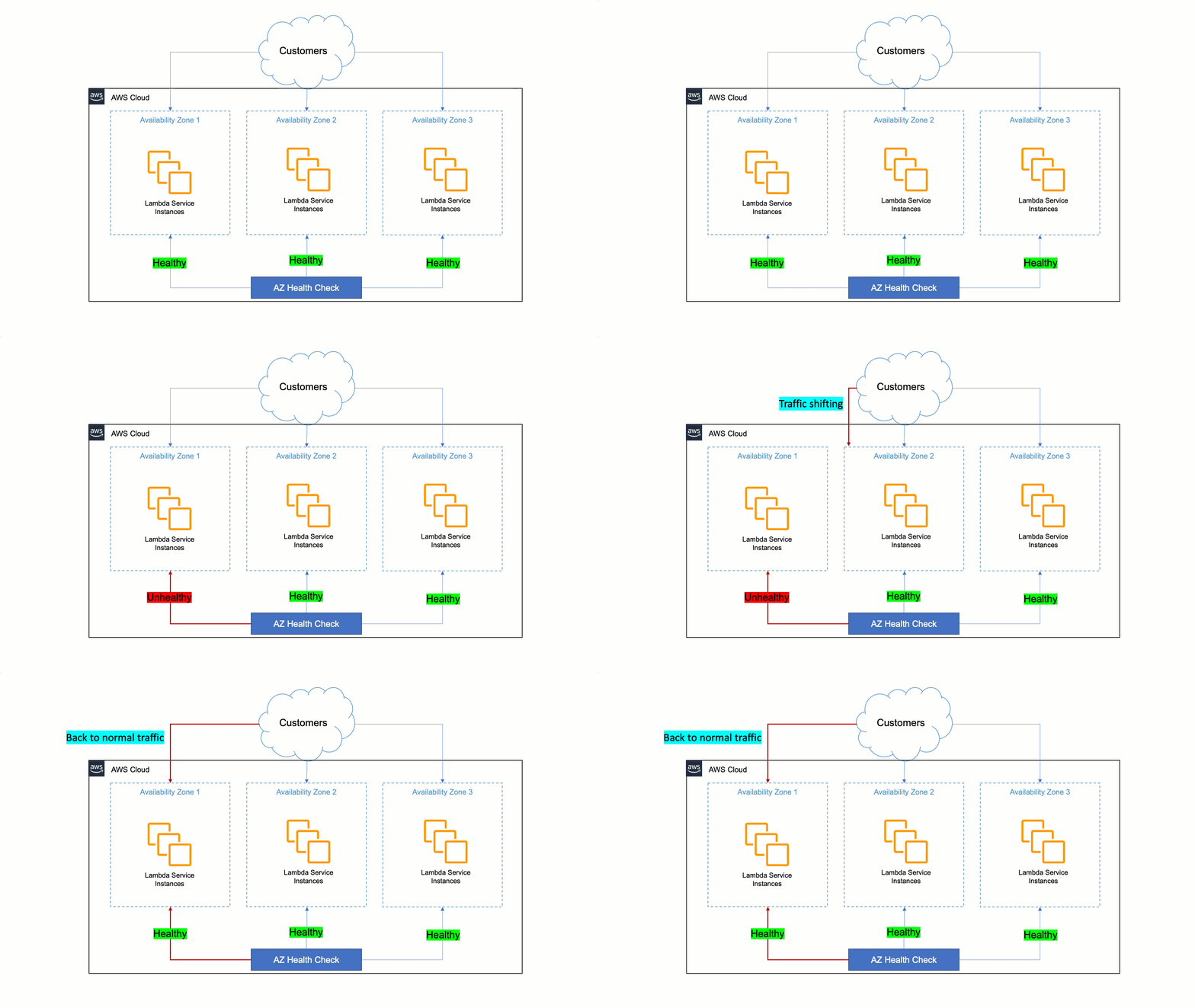
Lambda’s approach to being resilient to Availability Zone impairments is to rely on static stability and automated systems. Humans are slower than machines for detecting issues and mitigating them. Therefore, Lambda must ensure that its services can detect issues within a zonal replica and remediate automatically within minutes and with no operator intervention. This auto-remediation is done by shifting customer traffic away from the affected Availability Zone to healthy ones, and it is called Availability Zone evacuation.

To do this, Lambda built a tool that detects failures and performs the Availability Zone evacuation when needed. This tool does a statistical comparison of metrics between different Availability Zones and EC2 instances in order to identify unhealthy Availability Zones. If an Availability Zone is found to have issues, the tool starts the evacuation out of the unhealthy Availability Zone automatically. This automation cuts the time to the first action from 30 minutes to less than 3 minutes.
How AWS Lambda uses AWS FIS

To verify the automation continuously works as expected, Lambda performs a wide variety of tests, which includes Availability Zone failure testing in their pre-production environment. The main objective of these tests is to verify the services are statically stable in the presence of Availability Zone impairments, and to verify that the Availability Zone evacuation can be successfully initiated. The benefit of having an automated test is that teams can repeat it regularly and don’t need to have special skills. One click is all it takes to launch the test.

For these tests, Lambda uses AWS FIS to inject faults into their large fleet of EC2 instances. They use AWS FIS with support of the AWS System Manager (SSM) agent and resource filters to target their fleet of EC2 instances in a particular Availability Zone. This is a versatile approach that can inject resource faults, such as CPU and memory exhaustion, and networking faults, such as packet latency, loss, or drop.

Injecting packet loss or latency is very important, since these symptoms can have a serious impact on application and network performance. Indeed, latency and loss, even in small quantities, can create inefficiencies and prevent applications from running at their peak performance. For Lambda, being able to detect increased latency or loss before it affects customers is critical.

How to recover your applications rapidly from Availability Zones failures

You can build a similar solution to rapidly recover your applications from a zonal failure. The solution must have a mechanism to evacuate an impaired Availability Zone, a monitoring system that allows you to detect when a zonal replica is impaired, and a way to test the static stability of your system. AWS provides many tools and services that can help you build this solution to achieve Lambda’s resiliency strategy.

For performing Availability Zone evacuation, you can use the new zonal shift capability from Route 53 ARC, which at the time of writing is in preview. Zonal shift lets you evacuate an Availability Zone for applications that are uses Elastic Load Balancing. If you find out that a zonal replica is impaired or unhealthy, you can use zonal shift to evacuate the Availability Zone for a period of time, while the issue gets fixed.

For performing the zonal shift, you must detect when a zonal replica is unhealthy. Your application must provide a signal of its health per Availability Zone. There are two common ways to capture this signal. First, passively, you can check your metrics, like response times, HTTP status codes, and other metrics that can help track fatal errors in your applications. Or actively, using synthetic monitoring, which allows you to create synthetic requests against your production application to provide a more complete view of the customer experience.

Amazon CloudWatch Synthetics provides canaries, which are scripts that run on a schedule and perform synthetic requests in your application endpoints and APIs. Canaries perform the same actions as customers and continuously verify the customer experience. You can create a canary for each zonal replica of your application and monitor the results independently.

With this information, if the user experience diminishes in one of the replicas, you can start an Availability Zone evacuation using zonal shift and minimize the bad experience for the user while you find and fix the sources of the failure.

To ensure that you can successfully recover from a failure, you must test the solution in advance. Without testing, it is just an assumption. To prove or disprove your assumptions about your system’s capability to handle disruptive events such as issues within an Availability Zones, you can use FIS.

With FIS, you can inject faults simultaneously in multiple resources within the same failure domain, such as Availability Zones. FIS currently integrates with several AWS services including EC2, Amazon Elastic Kubernetes Service (Amazon EKS), Amazon Elastic Container Service (Amazon ECS), Amazon Relational Database Service (Amazon RDS), AWS Networking, and CloudWatch.

Typical use cases for testing a workload’s resilience to Availability Zones impairment are, for example, terminating all compute resources and databases within a particular Availability Zone, injecting latency or packet loss, increasing resource consumption (CPU, memory, and I/O) in compute resources in a particular Availability Zone, or impacting network communication within or between Availability Zones.

For more information and a step-by-step example of how to recover rapidly from application failures in a single Availability Zone and testing it with AWS FIS, read this blog post.

Conclusion

­­­This article discusses static stability, a mechanism that is used by AWS services such as Lambda to build resilient Regional services. It also discusses how AWS takes advantage of the same services and infrastructure as customers. It shows how Lambda uses multiple Availability Zones and services like AWS FIS to build highly available services and improve its recovery time from unexpected failures to only a few minutes without human intervention. Finally, it shows a solution that you can implement for your applications to achieve Lambda’s resilience strategy.

To learn more about AWS FIS, there are many tutorials and a workshop you can check out.

For more serverless learning resources, visit Serverless Land.

Enabling load-balancing of non-HTTP(s) traffic on AWS Wavelength

Post Syndicated from Sheila Busser original https://aws.amazon.com/blogs/compute/enabling-load-balancing-of-non-https-traffic-on-aws-wavelength/

This blog post is written by Jack Chen, Telco Solutions Architect, and Robert Belson, Developer Advocate.

AWS Wavelength embeds AWS compute and storage services within 5G networks, providing mobile edge computing infrastructure for developing, deploying, and scaling ultra-low-latency applications. AWS recently introduced support for Application Load Balancer (ALB) in AWS Wavelength zones. Although ALB addresses Layer-7 load balancing use cases, some low latency applications that get deployed in AWS Wavelength Zones rely on UDP-based protocols, such as QUIC, WebRTC, and SRT, which can’t be load-balanced by Layer-7 Load Balancers. In this post, we’ll review popular load-balancing patterns on AWS Wavelength, including a proposed architecture demonstrating how DNS-based load balancing can address customer requirements for load-balancing non-HTTP(s) traffic across multiple Amazon Elastic Compute Cloud (Amazon EC2) instances. This solution also builds a foundation for automatic scale-up and scale-down capabilities for workloads running in an AWS Wavelength Zone.

Load balancing use cases in AWS Wavelength

In the AWS Regions, customers looking to deploy highly-available edge applications often consider Amazon Elastic Load Balancing (Amazon ELB) as an approach to automatically distribute incoming application traffic across multiple targets in one or more Availability Zones (AZs). However, at the time of this publication, AWS-managed Network Load Balancer (NLB) isn’t supported in AWS Wavelength Zones and ALB is being rolled out to all AWS Wavelength Zones globally. As a result, this post will seek to document general architectural guidance for load balancing solutions on AWS Wavelength.

As one of the most prominent AWS Wavelength use cases, highly-immersive video streaming over UDP using protocols such as WebRTC at scale often require a load balancing solution to accommodate surges in traffic, either due to live events or general customer access patterns. These use cases, relying on Layer-4 traffic, can’t be load-balanced from a Layer-7 ALB. Instead, Layer-4 load balancing is needed.

To date, two infrastructure deployments involving Layer-4 load balancers are most often seen:

  • Amazon EC2-based deployments: Often the environment of choice for earlier-stage enterprises and ISVs, a fleet of EC2 instances will leverage a load balancer for high-throughput use cases, such as video streaming, data analytics, or Industrial IoT (IIoT) applications
  • Amazon EKS deployments: Customers looking to optimize performance and cost efficiency of their infrastructure can leverage containerized deployments at the edge to manage their AWS Wavelength Zone applications. In turn, external load balancers could be configured to point to exposed services via NodePort objects. Furthermore, a more popular choice might be to leverage the AWS Load Balancer Controller to provision an ALB when you create a Kubernetes Ingress.

Regardless of deployment type, the following design constraints must be considered:

  • Target registration: For load balancing solutions not managed by AWS, seamless solutions to load balancer target registration must be managed by the customer. As one potential solution, visit a recent HAProxyConf presentation, Practical Advice for Load Balancing at the Network Edge.
  • Edge Discovery: Although DNS records can be populated into Amazon Route 53 for each carrier-facing endpoint, DNS won’t deterministically route mobile clients to the most optimal mobile endpoint. When available, edge discovery services are required to most effectively route mobile clients to the lowest latency endpoint.
  • Cross-zone load balancing: Given the hub-and-spoke design of AWS Wavelength, customer-managed load balancers should proxy traffic only to that AWS Wavelength Zone.

Solution overview – Amazon EC2

In this solution, we’ll present a solution for a highly-available load balancing solution in a single AWS Wavelength Zone for an Amazon EC2-based deployment. In a separate post, we’ll cover the needed configurations for the AWS Load Balancer Controller in AWS Wavelength for Amazon Elastic Kubernetes Service (Amazon EKS) clusters.

The proposed solution introduces DNS-based load balancing, a technique to abstract away the complexity of intelligent load-balancing software and allow your Domain Name System (DNS) resolvers to distribute traffic (equally, or in a weighted distribution) to your set of endpoints.

Our solution leverages the weighted routing policy in Route 53 to resolve inbound DNS queries to multiple EC2 instances running within an AWS Wavelength zone. As EC2 instances for a given workload get deployed in an AWS Wavelength zone, Carrier IP addresses can be assigned to the network interfaces at launch.

Through this solution, Carrier IP addresses attached to AWS Wavelength instances are automatically added as DNS records for the customer-provided public hosted zone.

To determine how Route 53 responds to queries, given an arbitrary number of records of a public hosted zone, Route53 offers numerous routing policies:

Simple routing policy – In the event that you must route traffic to a single resource in an AWS Wavelength Zone, simple routing can be used. A single record can contain multiple IP addresses, but Route 53 returns the values in a random order to the client.

Weighted routing policy – To route traffic more deterministically using a set of proportions that you specify, this policy can be selected. For example, if you would like Carrier IP A to receive 50% of the traffic and Carrier IP B to receive 50% of the traffic, we’ll create two individual A records (one for each Carrier IP) with a weight of 50 and 50, respectively. Learn more about Route 53 routing policies by visiting the Route 53 Developer Guide.

The proposed solution leverages weighted routing policy in Route 53 DNS to route traffic to multiple EC2 instances running within an AWS Wavelength zone.

Reference architecture

The following diagram illustrates the load-balancing component of the solution, where EC2 instances in an AWS Wavelength zone are assigned Carrier IP addresses. A weighted DNS record for a host (e.g., www.example.com) is updated with Carrier IP addresses.

DNS-based load balancing

When a device makes a DNS query, it will be returned to one of the Carrier IP addresses associated with the given domain name. With a large number of devices, we expect a fair distribution of load across all EC2 instances in the resource pool. Given the highly ephemeral mobile edge environments, it’s likely that Carrier IPs could frequently be allocated to accommodate a workload and released shortly thereafter. However, this unpredictable behavior could yield stale DNS records, resulting in a “blackhole” – routes to endpoints that no longer exist.

Time-To-Live (TTL) is a DNS attribute that specifies the amount of time, in seconds, that you want DNS recursive resolvers to cache information about this record.

In our example, we should set to 30 seconds to force DNS resolvers to retrieve the latest records from the authoritative nameservers and minimize stale DNS responses. However, a lower TTL has a direct impact on cost, as a result of increased number of calls from recursive resolvers to Route53 to constantly retrieve the latest records.

The core components of the solution are as follows:

Alongside the services above in the AWS Wavelength Zone, the following services are also leveraged in the AWS Region:

  • AWS Lambda – a serverless event-driven function that makes API calls to the Route 53 service to update DNS records.
  • Amazon EventBridge– a serverless event bus that reacts to EC2 instance lifecycle events and invokes the Lambda function to make DNS updates.
  • Route 53– cloud DNS service with a domain record pointing to AWS Wavelength-hosted resources.

In this post, we intentionally leave the specific load balancing software solution up to the customer. Customers can leverage various popular load balancers available on the AWS Marketplace, such as HAProxy and NGINX. To focus our solution on the auto-registration of DNS records to create functional load balancing, this solution is designed to support stateless workloads only. To support stateful workloads, sticky sessions – a process in which routes requests to the same target in a target group – must be configured by the underlying load balancer solution and are outside of the scope of what DNS can provide natively.

Automation overview

Using the aforementioned components, we can implement the following workflow automation:

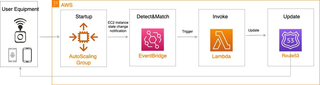
Event-driven Auto Scaling Workflow

Amazon CloudWatch alarm can trigger the Auto Scaling group Scale out or Scale in event by adding or removing EC2 instances. Eventbridge will detect the EC2 instance state change event and invoke the Lambda function. This function will update the DNS record in Route53 by either adding (scale out) or deleting (scale in) a weighted A record associated with the EC2 instance changing state.

Configuration of the automatic auto scaling policy is out of the scope of this post. There are many auto scaling triggers that you can consider using, based on predefined and custom metrics such as memory utilization. For the demo purposes, we will be leveraging manual auto scaling.

In addition to the core components that were already described, our solution also utilizes AWS Identity and Access Management (IAM) policies and CloudWatch. Both services are key components to building AWS Well-Architected solutions on AWS. We also use AWS Systems Manager Parameter Store to keep track of user input parameters. The deployment of the solution is automated via AWS CloudFormation templates. The Lambda function provided should be uploaded to an AWS Simple Storage Service (Amazon S3) bucket.

Amazon Virtual Private Cloud (Amazon VPC), subnets, Carrier Gateway, and Route Tables are foundational building blocks for AWS-based networking infrastructure. In our deployment, we are creating a new VPC, one subnet in an AWS Wavelength zone of your choice, a Carrier Gateway, and updating the route table for this subnet to point the default route to the Carrier Gateway.

Wavelength VPC architecture.

Deployment prerequisites

The following are prerequisites to deploy the described solution in your account:

  • Access to an AWS Wavelength zone. If your account is not allow-listed to use AWS Wavelength zones, then opt-in to AWS Wavelength zones here.
  • Public DNS Hosted Zone hosted in Route 53. You must have access to a registered public domain to deploy this solution. The zone for this domain should be hosted in the same account where you plan to deploy AWS Wavelength workloads.
    If you don’t have a public domain, then you can register a new one. Note that there will be a service charge for the domain registration.
  • Amazon S3 bucket. For the Lambda function that updates DNS records in Route 53, store the source code as a .zip file in an Amazon S3 bucket.
  • Amazon EC2 Key pair. You can use an existing Key pair for the deployment. If you don’t have a KeyPair in the region where you plan to deploy this solution, then create one by following these instructions.
  • 4G or 5G-connected device. Although the infrastructure can be deployed independent of the underlying connected devices, testing the connectivity will require a mobile device on one of the Wavelength partner’s networks. View the complete list of Telecommunications providers and Wavelength Zone locations to learn more.

Conclusion

In this post, we demonstrated how to implement DNS-based load balancing for workloads running in an AWS Wavelength zone. We deployed the solution that used the EventBridge Rule and the Lambda function to update DNS records hosted by Route53. If you want to learn more about AWS Wavelength, subscribe to AWS Compute Blog channel here.

Building highly resilient applications with on-premises interdependencies using AWS Local Zones

Post Syndicated from Sheila Busser original https://aws.amazon.com/blogs/compute/building-highly-resilient-applications-with-on-premises-interdependencies-using-aws-local-zones/

This blog post is written by Rachel Rui Liu, Senior Solutions Architect.

AWS Local Zones are a type of infrastructure deployment that places compute, storage, database, and other select AWS services close to large population and industry centers.

Following the successful launch of the AWS Local Zones in 16 US cities since 2019, in Feb 2022, AWS announced plans to launch new AWS Local Zones in 32 metropolitan areas in 26 countries worldwide.

With Local Zones, we’ve seen use cases in two common categories.

The first category of use cases is for workloads that require extremely low latency between end-user devices and workload servers. For example, let’s consider media content creation and real-time multiplayer gaming. For these use cases, deploying the workload to a Local Zone can help achieve down to single-digit milliseconds latency between end-user devices and the AWS infrastructure, which is ideal for a good end-user experience.

This post will focus on addressing the second category of use cases, which is commonly seen in an enterprise hybrid architecture, where customers must achieve low latency between AWS infrastructure and existing on-premises data centers.  Compared to the first category of use cases, these use cases can tolerate slightly higher latency between the end-user devices and the AWS infrastructure. However, these workloads have dependencies to these on-premises systems, so the lowest possible latency between AWS infrastructure and on-premises data centers is required for better application performance. Here are a few examples of these systems:

  • Financial services sector mainframe workloads hosted on premises serving regional customers.
  • Enterprise Active Directory hosted on premise serving cloud and on-premises workloads.
  • Enterprise applications hosted on premises processing a high volume of locally generated data.

For workloads deployed in AWS, the time taken for each interaction with components still hosted in the on-premises data center is increased by the latency. In turn, this delays responses received by the end-user. The total latency accumulates and results in suboptimal user experiences.

By deploying modernized workloads in Local Zones, you can reduce latency while continuing to access systems hosted in on-premises data centers, thereby reducing the total latency for the end-user. At the same time, you can enjoy the benefits of agility, elasticity, and security offered by AWS, and can apply the same automation, compliance, and security best practices that you’ve been familiar with in the AWS Regions.

Enterprise workload resiliency with Local Zones

While designing hybrid architectures with Local Zones, resiliency is an important consideration. You want to route traffic to the nearest Local Zone for low latency. However, when disasters happen, it’s critical to fail over to the parent Region automatically.

Let’s look at the details of hybrid architecture design based on real world deployments from different angles to understand how the architecture achieves all of the design goals.

Hybrid architecture with resilient network connectivity

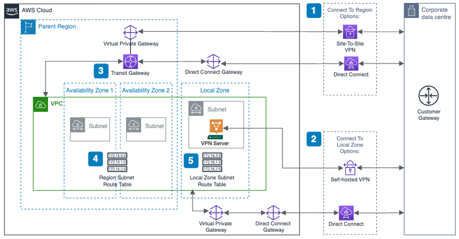
The following diagram shows a high-level overview of a resilient enterprise hybrid architecture with Local Zones, where you have redundant connections between the AWS Region, the Local Zone, and the corporate data center.

resillient network connectivity

Here are a few key points with this network connectivity design:

  1. Use AWS Direct Connect or Site-to-Site VPN to connect the corporate data center and AWS Region.
  2. Use Direct Connect or self-hosted VPN to connect the corporate data center and the Local Zone. This connection will provide dedicated low-latency connectivity between the Local Zone and corporate data center.
  3. Transit Gateway is a regional service. When attaching the VPC to AWS Transit Gateway, you can only add subnets provisioned in the Region. Instances on subnets in the Local Zone can still use Transit Gateway to reach resources in the Region.
  4. For subnets provisioned in the Region, the VPC route table should be configured to route the traffic to the corporate data center via Transit Gateway.
  5. For subnets provisioned in Local Zone, the VPC route table should be configured to route the traffic to the corporate data center via the self-hosted VPN instance or Direct Connect.

Hybrid architecture with resilient workload deployment

The next examples show a public and a private facing workload.

To simplify the diagram and focus on application layer architecture, the following diagrams assume that you are using Direct Connect to connect between AWS and the on-premises data center.

Example 1: Resilient public facing workload

With a public facing workload, end-user traffic will be routed to the Local Zone. If the Local Zone is unavailable, then the traffic will be routed to the Region automatically using an Amazon Route 53 failover policy.

public facing workload resilliency
Here are the key design considerations for this architecture:

  1. Deploy the workload in the Local Zone and put the compute layer in an AWS AutoScaling Group, so that the application can scale up and down depending on volume of requests.
  2. Deploy the workload in both the Local Zone and an AWS Region, and put the compute layer into an autoscaling group. The regional deployment will act as pilot light or warm standby with minimal footprint. But it can scale out when the Local Zone is unavailable.
  3. Two Application Load Balancers (ALBs) are required: one in the Region and one in the Local Zone. Each ALB will dispatch the traffic to each workload cluster inside the autoscaling group local to it.
  4. An internet gateway is required for public facing workloads. When using a Local Zone, there’s no extra configuration needed: define a single internet gateway and attach it to the VPC.

If you want to specify an Elastic IP address to be the workload’s public endpoint, the Local Zone will have a different address pool than the Region. Noting that BYOIP is unsupported for Local Zones.

  1. Create a Route 53 DNS record with “Failover” as the routing policy.
  • For the primary record, point it to the alias of the ALB in the Local Zone. This will set Local Zone as the preferred destination for the application traffic which minimizes latency for end-users.
  • For the secondary record, point it to the alias of the ALB in the AWS Region.
  • Enable health check for the primary record. If health check against the primary record fails, which indicates that the workload deployed in the Local Zone has failed to respond, then Route 53 will automatically point to the secondary record, which is the workload deployed in the AWS Region.

Example 2: Resilient private workload

For a private workload that’s only accessible by internal users, a few extra considerations must be made to keep the traffic inside of the trusted private network.

private workload resilliency

The architecture for resilient private facing workload has the same steps as public facing workload, but with some key differences. These include:

  1. Instead of using a public hosted zone, create private hosted zones in Route 53 to respond to DNS queries for the workload.
  2. Create the primary and secondary records in Route 53 just like the public workload but referencing the private ALBs.
  3. To allow end-users onto the corporate network (within offices or connected via VPN) to resolve the workload, use the Route 53 Resolver with an inbound endpoint. This allows end-users located on-premises to resolve the records in the private hosted zone. Route 53 Resolver is designed to be integrated with an on-premises DNS server.
  4. No internet gateway is required for hosting the private workload. You might need an internet gateway in the Local Zone for other purposes: for example, to host a self-managed VPN solution to connect the Local Zone with the corporate data center.

Hosting multiple workloads

Customers who host multiple workloads in a single VPC generally must consider how to segregate those workloads. As with workloads in the AWS Region, segregation can be implemented at a subnet or VPC level.

If you want to segregate workloads at the subnet level, you can extend your existing VPC architecture by provisioning extra sets of subnets to the Local Zone.

segregate workloads at subnet level

Although not shown in the diagram, for those of you using a self-hosted VPN to connect the Local Zone with an on-premises data center, the VPN solution can be deployed in a centralized subnet.

You can continue to use security groups, network access control lists (NACLs) , and VPC route tables – just as you would in the Region to segregate the workloads.

If you want to segregate workloads at the VPC level, like many of our customers do, within the Region, inter-VPC routing is generally handled by Transit Gateway. However, in this case, it may be undesirable to send traffic to the Region to reach a subnet in another VPC that is also extended to the Local Zone.

segregate workloads at VPC level

Key considerations for this design are as follows:

  1. Direct Connect is deployed to connect the Local Zone with the corporate data center. Therefore, each VPC will have a dedicated Virtual Private Gateway provisioned to allow association with the Direct Connect Gateway.
  2. To enable inter-VPC traffic within the Local Zone, peer the two VPCs together.
  3. Create a VPC route table in VPC A. Add a route for Subnet Y where the destination is the peering link. Assign this route table to Subnet X.
  4. Create a VPC route table in VPC B. Add a route for Subnet X where the destination is the peering link. Assign this route table to Subnet Y.
  5. If necessary, add routes for on-premises networks and the transit gateway to both route tables.

This design allows traffic between subnets X and Y to stay within the Local Zone, thereby avoiding any latency from the Local Zone to the AWS Region while still permitting full connectivity to all other networks.

Conclusion

In this post, we summarized the use cases for enterprise hybrid architecture with Local Zones, and showed you:

  • Reference architectures to host workloads in Local Zones with low-latency connectivity to corporate data centers and resiliency to enable fail over to the AWS Region automatically.
  • Different design considerations for public and private facing workloads utilizing this hybrid architecture.
  • Segregation and connectivity considerations when extending this hybrid architecture to host multiple workloads.

Hopefully you will be able to follow along with these reference architectures to build and run highly resilient applications with local system interdependencies using Local Zones.

Setup a high availability design for Oracle Data Guard (Fast-Start Failover) using Amazon Route 53

Post Syndicated from Viqash Adwani original https://aws.amazon.com/blogs/architecture/setup-a-high-availability-design-for-oracle-data-guard-fast-start-failover-using-amazon-route-53/

Many customers use Oracle Database deployed on Amazon Elastic Compute Cloud (Amazon EC2) to run their Oracle E-Business Suite applications. They rely on Oracle Data Guard for high availability databases, with a standby database running in a different availability zone. Oracle Data Guard can switch a standby database to the primary role in case a production database becomes unavailable due to planned/unplanned outage.

Oracle E-Business Suite has AutoConfig Database Context files that points to Domain Name System (DNS), like a private IP DNS name or IP address on Amazon EC2. In case of switchover/failover, Database Context files in Oracle E-Business Suite need to be updated. With this solution, database context files do not need to be updated in case of switchover/failover. This is achieved by providing a single DNS name hosted on Amazon Route 53, always pointing to a primary database irrespective of running on any node.

This post demonstrates setting up a Route 53 hosted zone that points to primary and standby databases and will route requests to the database having a primary role. We will setup Route 53 health checks to monitor Amazon CloudWatch alarms, based on Oracle Data Guard Fast-Start Failover (FSFO) logs pushed from Oracle Database using CloudWatch agent.

Prerequisites

Before getting started, you must have the following:

  • Oracle databases running on two separate EC2 instances for 1\Primary and 2\Standby node
  • EC2 instance for 3\Observer node, with either Oracle Client Administrator software or the full Oracle Database software stack
  • Oracle Data Guard configured to maintain standby databases as transactional consistent copy of the primary database
  • Oracle Data Guard Command-Line Interface (DGMGRL) configured with observer process to facilitate FSFO
  • FSFO enabled with observer configuration

Solution overview

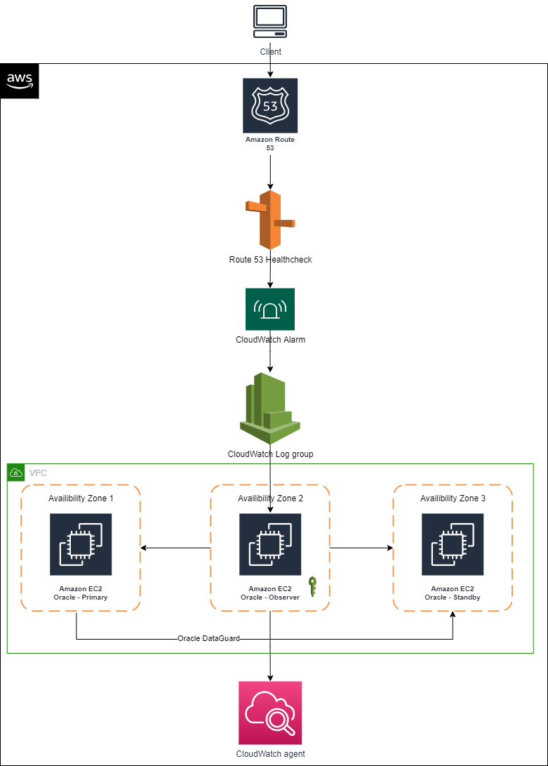
Figure 1 depicts AWS services that are used build an architecture using a single Domain Name System (DNS) and Route 53 to have requests route to the primary database for Oracle Data Guard deployed on EC2 instances.

Using a single DNS and Amazon Route 53 to route requests

Figure 1. Using a single DNS and Amazon Route 53 to route requests

We encourage you to explore these articles prior to launching this architecture:

Architecture components

  • Primary node: An Oracle Data Guard configuration contains one production database (primary database) that functions in the primary role. This is the database that is accessed by most of your applications.
  • Standby node: A standby database is a transactional consistent copy of the primary database. Once created, Oracle Data Guard automatically maintains each standby database by transmitting redo data from the primary database and applying it to the standby database.
  • Observer node: A component of DGMGRL that is configured on a separate server with Oracle Client Interface outside the systems running the Oracle Data Guard configuration, which monitors the availability of the primary database. We recommend it is in a separate availability zone than the primary and standby databases. Should it detect that the primary database is unavailable or the connection cannot be made, it will issue a failover after waiting for the 30 seconds or specified by the FastStartFailoverThreshold property.

Note: This solution was tested on Oracle Database 19c Enterprise Edition Release 19.0.0.0.0 and Oracle Enterprise Linux OL7.5-x86_64. Select the required combination of operating system and database by referring to E-Business Suite Database Certifications. Active Oracle Data Guard configuration is not used in this solution; therefore, the database stays in mount state and unavailable for customer reads. However, this solution can be used with an active Oracle Data Guard configuration as well.

Infrastructure setup

This table details the lab environment and the database instance names used throughout this post.

Database role IP address Instance name Database unique name Database open mode Database port
Primary node 172.31.xx.xx ORCLVIQ orclviq Read write 1522
Secondary node 172.31.xx.xx ORCLVIQ orclviq Mounted 1522
FSFO observer node 172.31.xx.xx
Route 53 hosted zone Dataguardviq.com Dataguardviq.com

Solution implementation

1. IAM policy

To configure the CloudWatch agent on an EC2 instance, create an IAM role via the console, AWS Command Line Interface, or AWS API. By default, an IAM role does not have any privileges and cannot access AWS resources. Before creating an IAM role, create an IAM policy with the permissions required to access CloudWatch logs, specifying the CloudWatch resources you want to monitor or *, which will allow access to CloudWatch logs.

Create the IAM policy using the following JSON and give it a name, like dgpolicy, which grants specific permissions. In this case, the permissions include creating log groups and log streams, inputting log events, and describing log stream for all logs.

{
    "Version": "2012-10-17",
    "Statement": [
        {
            "Action": [
                "logs:DescribeLogGroups",
                "logs:DescribeLogStreams",
                "logs:GetLogEvents",
                "s3:GetBucketLocation"
            ],
            "Effect": "Allow",
            "Resource": "*"
        }
    ]
}

2. IAM role

Create the IAM role (for example, dgrole) and attach the policy created in Step 1.

3. Associate IAM role with Amazon EC2 having FSFO observer node running on it

Associate the IAM role with Amazon EC2 from AWS console:

  1. Open the Amazon EC2 console.
  2. In the navigation pane, choose Instances.
  3. Select the instance, and choose Action, Security, Modify IAM role.
  4. Select the IAM role to attach to your instance; choose Save.

You also can use the associate-iam-instance-profile command to attach the IAM role to the instance by specifying the instance profile:

aws ec2 associate-iam-instance-profile \
    --instance-id i-1234567890lmnopq1 \
    --iam-instance-profile Name=" dgrole"

4. Install CloudWatch log agent on observer node

Install CloudWatch Logs agent on the observer node that already has FSFO log configuration setup on it. After installation is complete, logs will automatically flow from the instance to the log stream you created while installing the agent, as depicted in Figures 2 and 3.

$curl https://s3.amazonaws.com/aws-cloudwatch/downloads/latest/awslogs-agent-setup.py -O
$sudo python ./awslogs-agent-setup.py --region ap-southeast-2

Steps to install Amazon CloudWatch agent

Figure 2. Steps to install Amazon CloudWatch agent

Example of output

Figure 3. Example of output

At this point, FSFO logs are visible in CloudWatch logs. Perform a database switchover to confirm that logs are being published to CloudWatch logs.

5. Create CloudWatch metric filter

Create primary metric filter

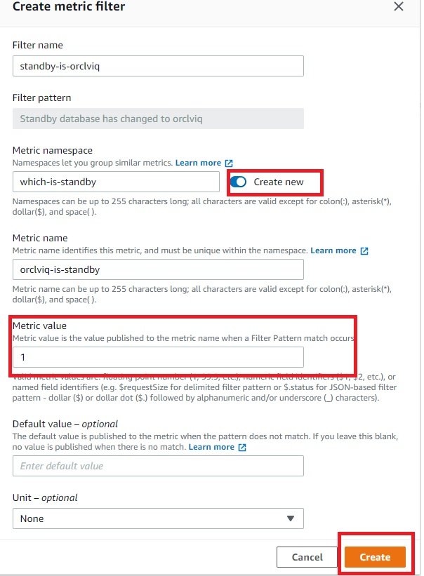
  • Create metric filter on “Standby database has changed to orclviq” and set value to “1”.
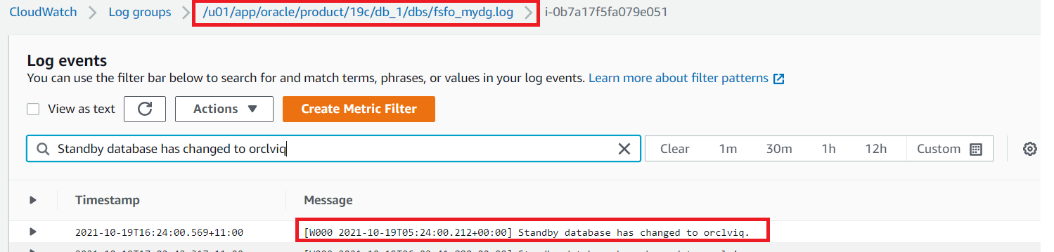
  • Open the CloudWatch log group and search for “Standby database has changed to orclviq“. Once results are displayed, “Create Metric Filter” button will appear at top right (as demonstrated in Figure 4).
Amazon CloudWatch log group

Figure 4. Amazon CloudWatch log group

  • Filter name” and “Filter pattern” are filled automatically, as we already filtered that while accessing the CloudWatch log. Create a new name space in the metric, which we will later use in second metric filter. Specify “Metric namespace”, which will also be the same for the second metric filter. “Metric value” is “1”, as detailed in Figure 5.
Amazon CloudWatch metric filter

Figure 5. Amazon CloudWatch metric filter

Create secondary metric filter

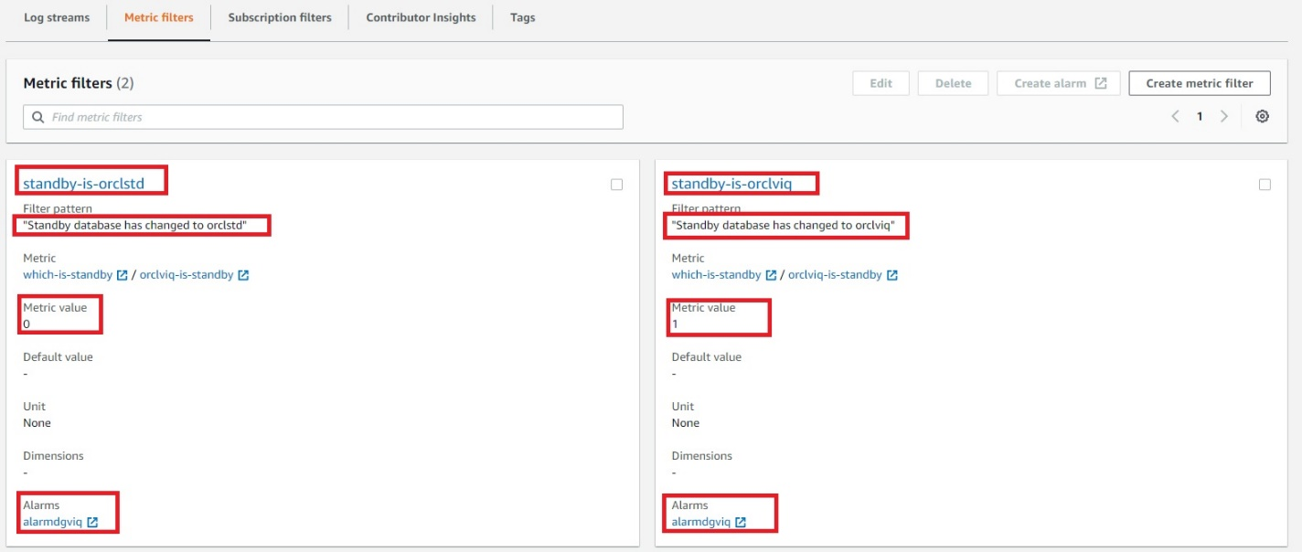
  • To create a second metric filter, follow steps to create the primary metric filter but the filter pattern will be “Standby database has changed to orclstd“. The only difference in this step will be setting the “Metric value” to “0”.
  • Verify the metric filter is working and able to find desired entries in the FSFO logs that will decide which instance is the primary database by:
    • Click on one of the metric filters
    • Select log data to test, and choose and EC2 instance ID
    • Testing the pattern to verify if metric filters are working properly
    • Select “Next”
    • Save changes

6. Create a CloudWatch alarm

Create a CloudWatch alarm that will monitor CloudWatch metrics and perform actions based on the value of the metric.

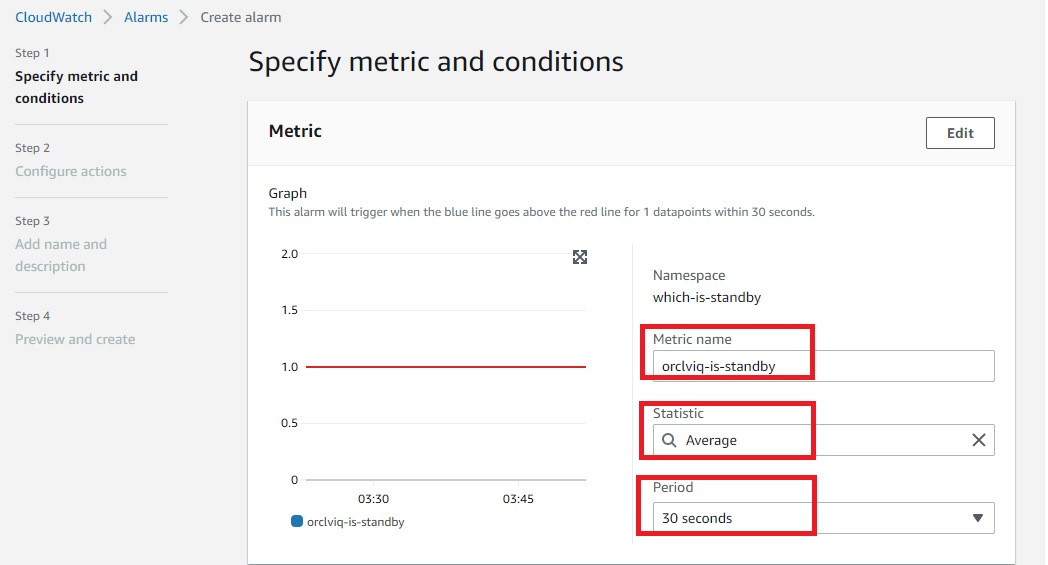
  • Within CloudWatch Alarms section (Step 1), select “Create alarm” and then select “Metric”, as in Figure 6.
  • In Step 2, you can create a new topic and specify the email address where you would like to receive notifications regarding changes in primary or standby database.
  • In Step 3, you can specify the alarm name and optional alarm description.
Amazon CloudWatch alarm

Figure 6. Amazon CloudWatch alarm

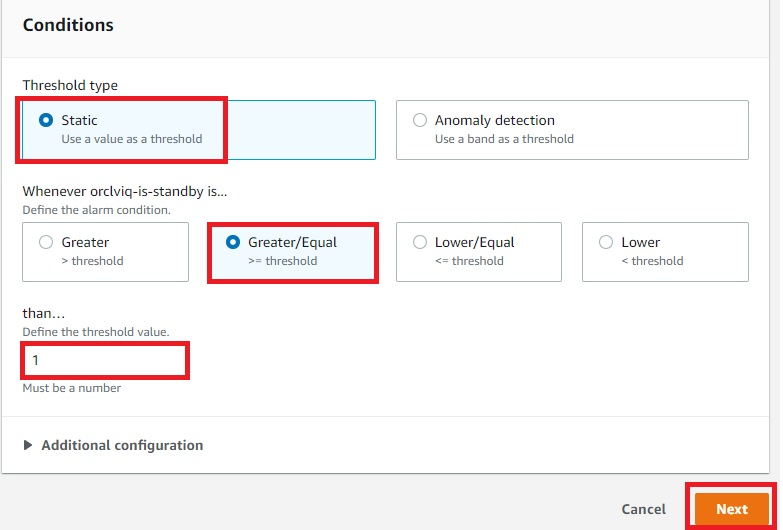
  • To configure Conditions, as detailed in Figure 7, be sure the threshold type is set to “Static”, the alarm condition is “Greater/Equal”, and the threshold value is “1”.
Amazon CloudWatch alarm condition

Figure 7. Amazon CloudWatch alarm condition

  • Figure 8 demonstrates the summary of the ready CloudWatch metrics and configured alarm.  At this point, “orclviq” is the primary database, so the alarm state will be “Insufficient data”. Try to do a switchover and the alarm state should be changed to “In alarm”.
  • Switch it back to original primary before proceeding further
Final view of both metric filters combined

Figure 8. Final view of both metric filters combined

7. Create Route 53 health checks

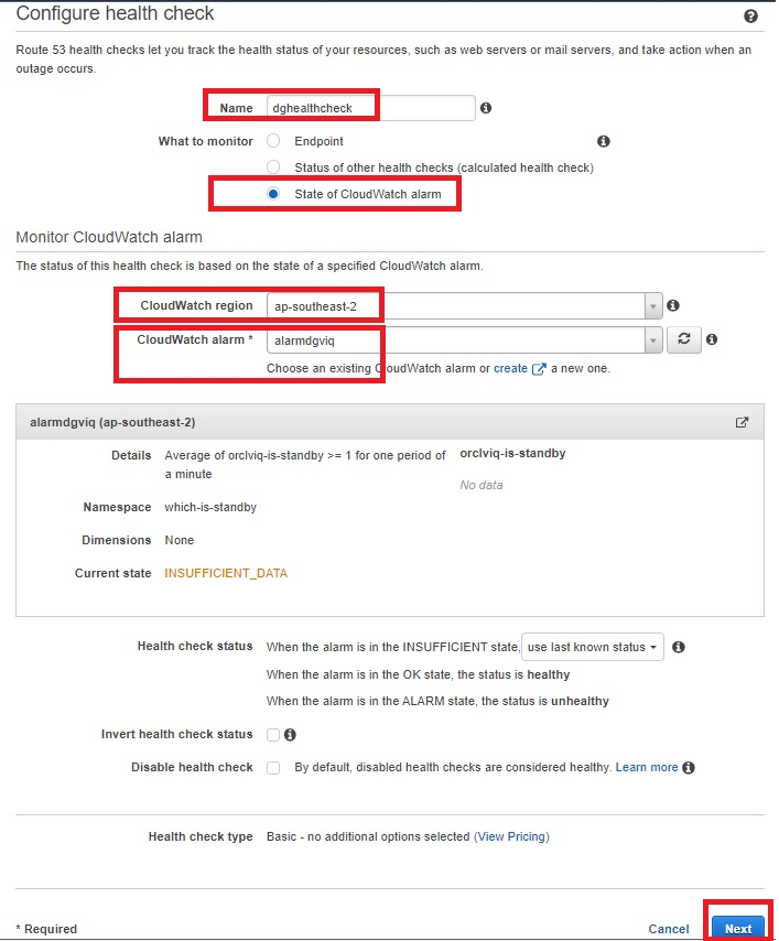
Creating Route 53 health checks based on the CloudWatch alarm identifies DNS failover. Health checks can be created on public IP directly without creating above metric filters and alarms, but it is unlikely that customers will have a public IP on database servers. Route 53 cannot check the health of an IP address endpoint despite if it is local, private, non-routable, or multi-cast ranges. Therefore, health checks will have to be created on the state of CloudWatch alarm (Figure 9):

  • Within the Route 53 console, select “Configure health check”.
  • Select “State of CloudWatch alarm”, then select the region of your CloudWatch metrics and choose the CloudWatch alarm that was created earlier from the dropdown menu.
  • Skip creating an alarm for health check, as the alarm is already configured for CloudWatch metric filter.
Amazon Route 53 health check parameters

Figure 9. Amazon Route 53 health check parameters

  • The health check is now ready and status will be “Unknown”. It will change to “Healthy”, as it is currently having primary orclviq, which means it’s satisfying “Standby database has changed to orclstd“.
  • At this point, try doing a failover and observe if health check status changes to “Unhealthy”. Switch it back to the original primary before proceeding.
  • The health check should return to “Healthy” state.
  • Check the status of the alarm:
    • OK: the status is healthy
    • ALARM: the status is unhealthy
    • INSUFFICIENT: use last known status

8. Create Route 53 hosted zone

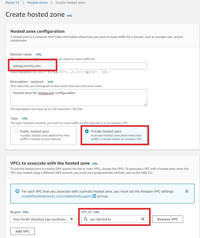
A Route 53 hosted zone in this solution will have failover routing based on records pointing to IP addresses of primary and standby database server. When the Route 53 health check is in an “Unhealthy” state, failover routing kicks in and the hosted zone starts routing requests to the IP address of the standby database server.

  • A Route 53 hosted zone will have records of your primary and standby database instance private IP. Because it is a private hosted zone, it will use the same VPC as the observer node on which we deployed the CloudWatch agent (Figure 10).
Amazon Route 53 hosted zone

Figure 10. Amazon Route 53 hosted zone

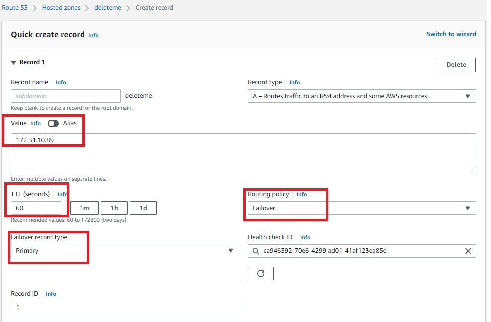
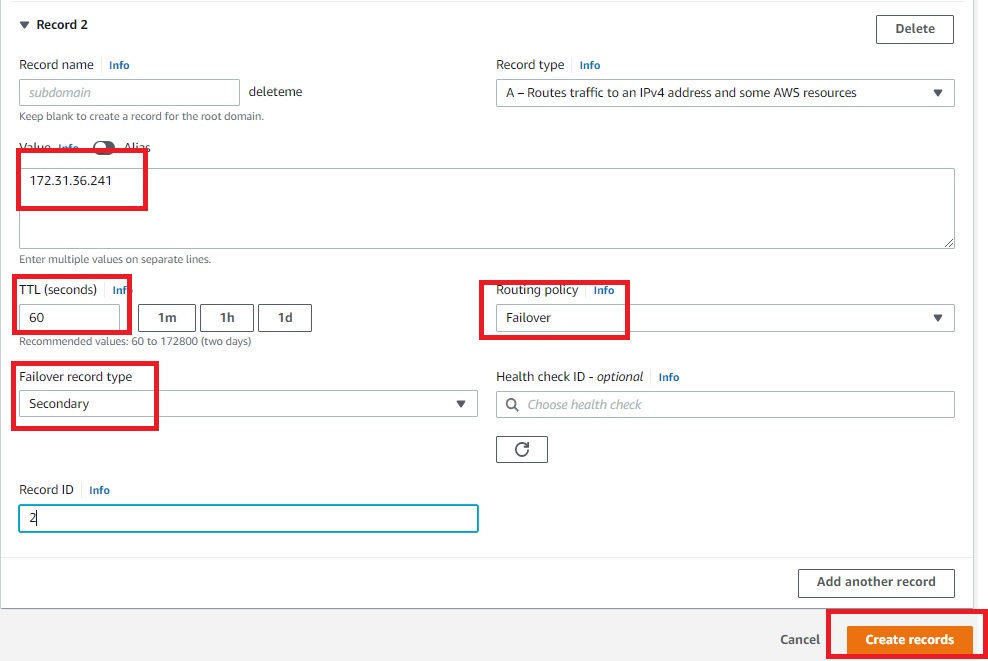
  • Once the Route 53 hosted zone is ready, the last step is to create records by adding private IP addresses of primary and secondary database servers (Figures 11 and 12). Routing policy is set as a failover. That means, if the Route 53 health check fails, the hosted zone does a DNS failover to standby server IP.
Amazon Route 53 hosted zone record for primary servers

Figure 11. Amazon Route 53 hosted zone record for primary servers

Amazon Route 53 hosted zone record for secondary servers

Figure 12. Amazon Route 53 hosted zone record for secondary servers

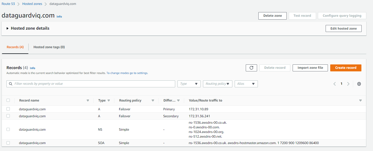
Once the records are created, the hosted zone will have an IP address of primary and secondary database servers, as demonstrated in Figure 13.

Final view of Amazon Route 53 hosted zone

Figure 13. Final view of Amazon Route 53 hosted zone

Solution testing

To test the solution, do a telnet utility test to evaluate network connectivity on the Route 53 hosted zone that was created. It should display the IP address of the primary database server: 172.31.10.89.

[ec2-user@ip-172-xx-xx-xx ~]$ telnet dataguardviq.com 1522
Trying 172.31.10.89…
Connected to dataguardviq.com.
Escape character is ‘^]’.

Next, perform a switchover or failover of the primary to secondary database server. This can be done with the DGMGRL command “switchover to orclstd”. Output will be:

DGMGRL> switchover to orclstd;
Performing switchover NOW, please wait…
Operation requires a connection to database “orclstd”
Connecting …
Connected to “orclstd”
Connected as SYSDBA.
New primary database “orclstd” is opening…
Oracle Clusterware is restarting database “orclviq” …
Connected to an idle instance.
Connected to “orclviq”
Switchover succeeded, new primary is “orclstd”

Now, the new primary is “orclstd”. In the backend, the Route 53 health check will be initiated and cause a failover. This means the telnet Route 53 hosted zone will give the IP address of the new primary (old secondary), which is 172.31.36.241.

[ec2-user@ip-172-xx-xx-xx ~]$ telnet dataguardviq.com 1522
Trying 172.31.36.241…
Connected to dataguardviq.com.
Escape character is ‘^]’.

Cleanup

To cleanup, remove:

  • Route 53 host zone
  • CloudWatch metric filter
  • CloudWatch alarm
  • CloudWatch agent from observer node
  • IAM role and policy created specifically for this solution

Conclusion

This solution demonstrated how to use a Route 53 hosted zone to route requests to the active primary node for Oracle Data Guard on Amazon EC2.

A multi-dimensional approach helps you proactively prepare for failures, Part 3: Operations and process resiliency

Post Syndicated from Piyali Kamra original https://aws.amazon.com/blogs/architecture/a-multi-dimensional-approach-helps-you-proactively-prepare-for-failures-part-3-operations-and-process-resiliency/

In Part 1 and Part 2 of this series, we discussed how to build application layer and infrastructure layer resiliency.

In Part 3, we explore how to develop resilient applications, and the need to test and break our operational processes and run books. Processes are needed to capture baseline metrics and boundary conditions. Detecting deviations from accepted baselines requires logging, distributed tracing, monitoring, and alerting. Testing automation and rollback are part of continuous integration/continuous deployment (CI/CD) pipelines. Keeping track of network, application, and system health requires automation.

In order to meet recovery time and point objective (RTO and RPO, respectively) requirements of distributed applications, we need automation to implement failover operations across multiple layers. Let’s explore how a distributed system’s operational resiliency needs to be addressed before it goes into production, after it’s live in production, and when a failure happens.

Pattern 1: Standardize and automate AWS account setup

Create processes and automation for onboarding users and providing access to AWS accounts according to their role and business unit, as defined by the organization. Federated access to AWS accounts and organizations simplifies cost management, security implementation, and visibility. Having a strategy for a suitable AWS account structure can reduce the blast radius in case of a compromise.

  1. Have auditing mechanisms in place. AWS CloudTrail monitors compliance, improving security posture, and auditing all the activity records across AWS accounts.
  2. Practice the least privilege security model when setting up access to the CloudTrail audit logs plus network and applications logs. Follow best practices on service control policies and IAM boundaries to help ensure your AWS accounts stay within your organization’s access control policies.
  3. Explore AWS Budgets, AWS Cost Anomaly Detection, and AWS Cost Explorer for cost-optimizing techniques. The AWS Compute Optimizer and Instance Scheduler on AWS resource resizing and auto-shutdown for non-working hours. A Beginner’s Guide to AWS Cost Management explores multiple cost-optimization techniques.
  4. Use AWS CloudFormation and AWS Config to detect infrastructure drift and take corrective actions to make resources compliant, as demonstrated in Figure 1.
Compliance control and drift detection

Figure 1. Compliance control and drift detection

Pattern 2: Documenting knowledge about the distributed system

Document high-level infrastructure and dependency maps.

Define availability characteristics of distributed system. Systems have components with varying RTO and RPO needs. Document application component boundaries and capture dependencies with other infrastructure components, including Domain Name System (DNS), IAM permissions; and access patterns, secrets, and certificates. Discover dependencies through solutions, such as Workload Discovery on AWS, to plan resiliency methods and ensure the order of execution of various steps during failover are correct.

Capture non-functional requirements (NFRs), such as business key performance indicators (KPIs), RTO, and RPO, for your composing services. NFRs are quantifiable and define system availability, reliability, and recoverability requirements. They should include throughput, page-load, and response time requirements. Quantify the RTO and RPO of different components of the distributed system by defining them. The KPIs measure if you are meeting the business objectives. As mentioned in Part 2: Infrastructure layer, RTO and RPO help define the failover and data recovery procedures.

Pattern 3: Define CI/CD pipelines for application code and infrastructure components

Establish a branching strategy. Implement automated checks for version and tagging compliance in feature/sprint/bug fix/hot fix/release candidate branches, according to your organization’s policies. Define appropriate release management processes and responsibility matrices, as demonstrated in Figures 2 and 3.

Test at all levels as part of an automated pipeline. This includes security, unit, and system testing. Create a feedback loop that provides the ability to detect issues and automate rollback in case of production failures, which are indicated by business KPI negative impact and other technical metrics.

Define the release management process

Figure 2. Define the release management process

Sample roles and responsibility matrix

Figure 3. Sample roles and responsibility matrix

Pattern 4: Keep code in a source control repository, regardless of GitOps

Merge requests and configuration changes follow the same process as application software. Just like application code, manage infrastructure as code (IaC) by checking the code into a source control repository, submitting pull requests, scanning code for vulnerabilities, alerting and sending notifications, running validation tests on deployments, and having an approval process.

You can audit your infrastructure drift, design reusable and repeatable patterns, and adhere to your distributed application’s RTO objectives by building your IaC (Figure 4). IaC is crucial for operational resilience.

CI/CD pipeline for deploying IaC

Figure 4. CI/CD pipeline for deploying IaC

Pattern 5: Immutable infrastructure

An immutable deployment pipeline launches a set of new instances running the new application version. You can customize immutability at different levels of granularity depending on which infrastructure part is being rebuilt for new application versions, as in Figure 5.

The more immutable infrastructure components being rebuilt, the more expensive deployments are in both deployment time and actual operational costs. Immutable infrastructure also is easier to rollback.

Different granularity levels of immutable infrastructure

Figure 5. Different granularity levels of immutable infrastructure

Pattern 6: Test early, test often

In a shift-left testing approach, begin testing in the early stages, as demonstrated in Figure 6. This can surface defects that can be resolved in a more time- and cost-effective manner compared with after code is released to production.

Shift-left test strategy

Figure 6. Shift-left test strategy

Continuous testing is an essential part of CI/CD. CI/CD pipelines can implement various levels of testing to reduce the likelihood of defects entering production. Testing can include: unit, functional, regression, load, and chaos.

Continuous testing requires testing and breaking existing boundary conditions, and updating test cases if the boundaries have changed. Test cases should test distributed systems’ idempotency. Chaos testing benefits our incidence response mechanisms for distributed systems that have multiple integration points. By testing our auto scaling and failover mechanisms, chaos testing improves application performance and resiliency.

AWS Fault Injection Simulator (AWS FIS) is a service for chaos testing. An experiment template contains actions, such as StopInstance and StartInstance, along with targets on which the test will be performed. In addition, you can mention stop conditions and check if they triggered the required Amazon CloudWatch alarms, as demonstrated in Figure 7.

AWS Fault Injection Simulator architecture for chaos testing

Figure 7. AWS Fault Injection Simulator architecture for chaos testing

Pattern 7: Providing operational visibility

In production, operational visibility across multiple dimensions is necessary for distributed systems (Figure 8). To identify performance bottlenecks and failures, use AWS X-Ray and other open-source libraries for distributed tracing.

Write application, infrastructure, and security logs to CloudWatch. When metrics breach alarm thresholds, integrate the corresponding alarms with Amazon Simple Notification Service or a third-party incident management system for notification.

Monitoring services, such as Amazon GuardDuty, are used to analyze CloudTrail, virtual private cloud flow logs, DNS logs, and Amazon Elastic Kubernetes Service audit logs to detect security issues. Monitor AWS Health Dashboard for maintenance, end-of-life, and service-level events that could affect your workloads. Follow the AWS Trusted Advisor recommendations to ensure your accounts follow best practices.

Dimensions for operational visibility

Figure 8. Dimensions for operational visibility (click the image to enlarge)

Figure 9 explores various application and infrastructure components integrating with AWS logging and monitoring components for increased problem detection and resolution, which can provide operational visibility.

Tooling architecture to provide operational visibility

Figure 9. Tooling architecture to provide operational visibility

Having an incident response management plan is an important mechanism for providing operational visibility. Successful execution of this requires educating the stakeholders on the AWS shared responsibility model, simulation of anticipated and unanticipated failures, documentation of the distributed system’s KPIs, and continuous iteration. Figure 10 demonstrates the features of a successful incidence response management plan.

An incidence response management plan

Figure 10. An incidence response management plan (click the image to enlarge)

Conclusion

In Part 3, we discussed continuous improvement of our processes by testing and breaking them. In order to understand the baseline level metrics, service-level agreements, and boundary conditions of our system, we need to capture NFRs. Operational capabilities are required to capture deviations from baseline, which is where alerting, logging, and distributed tracing come in. Processes should be defined for automating frequent testing in CI/CD pipelines, detecting network issues, and deploying alternate infrastructure stacks in failover regions based on RTOs and RPOs. Automating failover steps depends on metrics and alarms, and by using chaos testing, we can simulate failover scenarios.

Prepare for failure, and learn from it. Working to maintain resilience is an ongoing task.

Want to learn more?

How to automate updates for your domain list in Route 53 Resolver DNS Firewall

Post Syndicated from Guillaume Neau original https://aws.amazon.com/blogs/security/how-to-automate-updates-for-your-domain-list-in-route-53-resolver-dns-firewall/

Note: This post includes links to third-party websites. AWS is not responsible for the content on those websites.


Following the release of Amazon Route 53 Resolver DNS Firewall, Amazon Web Services (AWS) published several blog posts to help you protect your Amazon Virtual Private Cloud (Amazon VPC) DNS resolution, including How to Get Started with Amazon Route 53 Resolver DNS Firewall for Amazon VPC and Secure your Amazon VPC DNS resolution with Amazon Route 53 Resolver DNS Firewall. Route 53 Resolver DNS Firewall provides managed domain lists that are fully maintained and kept up-to-date by AWS and that directly benefit from the threat intelligence that we gather, but you might want to create or import your own list to have full control over the DNS filtering.

In this blog post, you will find a solution to automate the management of your domain list by using AWS Lambda, Amazon EventBridge, and Amazon Simple Storage Service (Amazon S3). The solution in this post uses, as an example, the URLhaus open Response Policy Zone (RPZ) list, which generates a new file every five minutes.

Architecture overview

The solution is made of the following four components, as shown in Figure 1.

  1. An EventBridge scheduled rule to invoke the Lambda function on a schedule.
  2. A Lambda function that uses the AWS SDK to perform the automation logic.
  3. An S3 bucket to temporarily store the list of domains retrieved.
  4. Amazon Route 53 Resolver DNS Firewall.
    Figure 1: Architecture overview

    Figure 1: Architecture overview

After the solution is deployed, it works as follows:

  1. The scheduled rule invokes the Lambda function every 5 minutes to fetch the latest domain list available.
  2. The Lambda function fetches the list from URLhaus, parses the data retrieved, formats the data, uploads the list of domains into the S3 bucket, and invokes the Route 53 Resolver DNS Firewall importFirewallDomains API action.
  3. The domain list is then updated.

Implementation steps

As a first step, create your own domain list on the Route 53 Resolver DNS Firewall. Having your own domain list allows you to have full control of the list of domains to which you want to apply actions, as defined within rule groups.

To create your own domain list

  1. In the Route 53 console, in the left menu, choose Domain lists in the DNS firewall section.
  2. Choose the Add domain list button, enter a name for your owned domain list, and then enter a placeholder domain to initialize the domain list.
  3. Choose Add domain list to finalize the creation of the domain list.
    Figure 2: Expected view of the console

    Figure 2: Expected view of the console

The list from URLhaus contains more than a thousand records. You will use the ImportFirewallDomains endpoint to upload this list to DNS Firewall. The use of the ImportFirewallDomains endpoint requires that you first upload the list of domains and make the list available in an S3 bucket that is located in the same AWS Region as the owned domain list that you just created.

To create the S3 bucket

  1. In the S3 console, choose Create bucket.
  2. Under General configuration, configure the AWS Region option to be the same as the Region in which you created your domain list.
  3. Finalize the configuration of your S3 bucket, and then choose Create bucket.

Because a new file is created every five minutes, we recommend setting a lifecycle rule to automatically expire and delete files after 24 hours to optimize for cost and only save the most recent lists.

To create the Lambda function

  1. Follow the steps in the topic Creating an execution role in the IAM console to create an execution role. After step 4, when you configure permissions, choose Create Policy, and then create and add an IAM policy similar to the following example. This policy needs to:
    • Allow the Lambda function to put logs in Amazon CloudWatch.
    • Allow the Lambda function to have read and write access to objects placed in the created S3 bucket.
    • Allow the Lambda function to update the firewall domain list.
    • {
          "Version": "2012-10-17",
          "Statement": [
              {
                  "Action": [
                      "logs:CreateLogGroup",
                      "logs:CreateLogStream",
                      "logs:PutLogEvents"
                  ],
                  "Resource": "arn:aws:logs:<region>:<accountId>:*",
                  "Effect": "Allow"
              },
              {
                  "Action": [
                      "s3:PutObject",
                      "s3:GetObject"
                  ],
                  "Resource": "arn:aws:s3:::<DNSFW-BUCKET-NAME>/*",
                  "Effect": "Allow"
              },
              {
                  "Action": [
                      "route53resolver:ImportFirewallDomains"
                  ],
                  "Resource": "arn:aws:route53resolver:<region>:<accountId>:firewall-domain-list/<domain-list-id>",
                  "Effect": "Allow"
              }
          ]
      }

  2. (Optional) If you decide to use the example provided by AWS:
    • After cloning the repository: Build the layer following the instruction included in the readme.md and the provided script.
    • Zip the lambda.
    • In the left menu, select Layers then Create Layer. Enter a name for the layer, then select Upload a .zip file. Choose to upload the layer (node-axios-layer.zip).
    • As a compatible runtime, select: Node.js 16.x.
    • Select Create
  3. In the Lambda console, in the same Region as your domain list, choose Create function, and then do the following:
    • Choose your desired runtime and architecture.
    • (Optional) To use the code provided by AWS: Select Node.js 16.x as the runtime.
    • Choose Change the default execution role.
    • Choose Use an existing role, and then pick the role that you just created.
  4. After the Lambda function is created, in the left menu of the Lambda console, choose Functions, and then select the function you created.
    • For Code source, you can either enter the code of the Lambda function or choose the Upload from button and then choose the source for the code. AWS provides an example of functioning code on GitHub under a MIT-0 license.

    (optional) To use the code provided by AWS:

    • Choose the Upload from button and upload the zipped code example.
    • After the code is uploaded, edit the default Runtime settings: Choose the Edit button and set the handler to be equal to: LambdaRpz.handler
    • Edit the default Layers configuration, choose the Add a layer button, select Specify an ARN and enter the ARN of the layer created during the optional step 2.
    • Edit the environment variables of the function: Select the Edit button and define the three following variables:
      1. Key : FirewallDomainListId | Value : <domain-list-id>
      2. Key : region | Value : <region>
      3. Key : s3Prefix | Value : <DNSFW-BUCKET-NAME>

The code that you place in the function will be able to fetch the list from URLhaus, upload the list as a file to S3, and start the import of domains.

For the Lambda function to be invoked every 5 minutes, next you will create a scheduled rule with Amazon EventBridge.

To automate the invoking of the Lambda function

  1. In the EventBridge console, in the same AWS Region as your domain list, choose Create rule.
  2. For Rule type, choose Schedule.
  3. For Schedule pattern, select the option A schedule that runs at a regular rate, such as every 10 minutes, and under Rate expression set a rate of 5 minutes.
    Figure 3: Console view when configuring a schedule

    Figure 3: Console view when configuring a schedule

  4. To select the target, choose AWS service, choose Lambda function, and then select the function that you previously created.

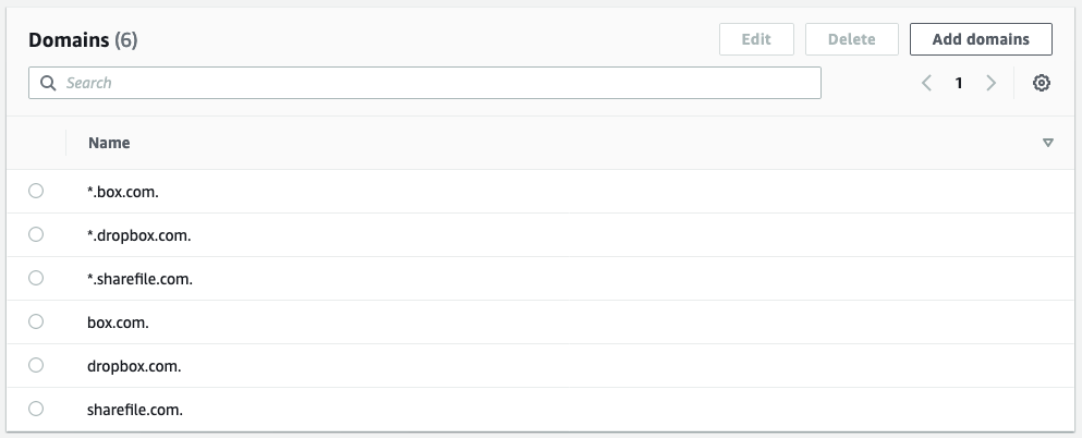
After the solution is deployed, your domain list will be updated every 5 minutes and look like the view in Figure 4.

Figure 4: Console view of the created domain list after it has been updated by the Lambda function

Figure 4: Console view of the created domain list after it has been updated by the Lambda function

Code samples

You can use the samples in the amazon-route-53-resolver-firewall-automation-examples-2 GitHub repository to ease the automation of your domain list, and the associated updates. The repository contains script files to help you with the deployment process of the AWS CloudFormation template. Note that you need to have the AWS Command Line Interface (AWS CLI) installed and properly configured in order to use the files.

To deploy the CloudFormation stack

  1. If you haven’t done so already, create an S3 bucket to store the artifacts in the Region where you wish to deploy. This name of this bucket will then be referenced as ParamS3ArtifactBucket with a value of <DOC-EXAMPLE-BUCKET-ARTIFACT>
  2. Clone the repository locally.
    git clone https://github.com/aws-samples/amazon-route-53-resolver-firewall-automation-examples-2
  3. Build the Lambda function layer. From the /layer folder, use the provided script.
    . ./build-layer.sh
  4. Zip and upload the artifact to the bucket created in step 1. From the root folder, use the provided script.
    . ./zipupload.sh <ParamS3ArtifactBucket>
  5. Deploy the AWS CloudFormation stack by using either the AWS CLI or the CloudFormation console.
    • To deploy by using the AWS CLI, from the root folder, type the following command, making sure to replace <region>, <DOC-EXAMPLE-BUCKET-ARTIFACT>, <DNSFW-BUCKET-NAME>, and <DomainListName>with your own values.
      aws --region <region> cloudformation create-stack --stack-name DNSFWStack --capabilities CAPABILITY_NAMED_IAM --template-body file://./DNSFWStack.cfn.yaml --parameters ParameterKey=ParamS3ArtifactBucket,ParameterValue=<DOC-EXAMPLE-BUCKET-ARTIFACT> ParameterKey=ParamS3RpzBucket,ParameterValue=<DNSFW-BUCKET-NAME> ParameterKey=ParamFirewallDomainListName,ParameterValue=<DomainListName>

    • To deploy by using the console, do the following:
      1. In the CloudFormation console, choose Create stack, and then choose With new resources (standard).
      2. On the creation screen, choose Template is ready, and upload the provided DNSFWStack.cfn.yaml file.
      3. Enter a stack name and configure the requested parameters with your desired configuration and outcomes. These parameters include the following:
        • The name of your firewall domain list.
        • The name of the S3 bucket that contains Lambda artifacts.
        • The name of the S3 bucket that will be created to contain the files with the domain information from URLhaus.
      4. Acknowledge that the template requires IAM permission because it will create the role for the Lambda function and manage its IAM policy, and then choose Create stack.

After a few minutes, all the resources should be created and the CloudFormation stack is now deployed. After 5 minutes, your domain list should be updated, as shown in Figure 5.

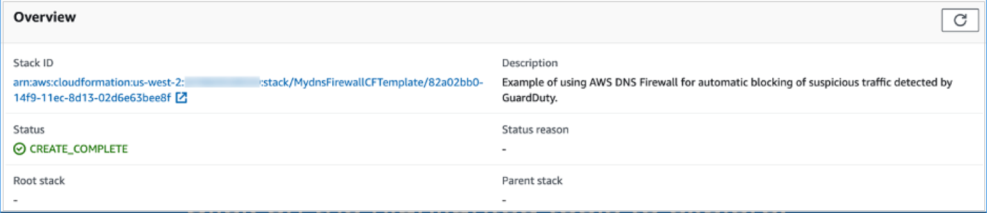
Figure 5: Console view of CloudFormation after the stack has been deployed

Figure 5: Console view of CloudFormation after the stack has been deployed

Conclusions and cost

In this blog post, you learned about creating and automating the update of a domain list that you fully control. To go further, you can extend and replicate the architecture pattern to fetch domain names from other sources by editing the source code of the Lambda function.

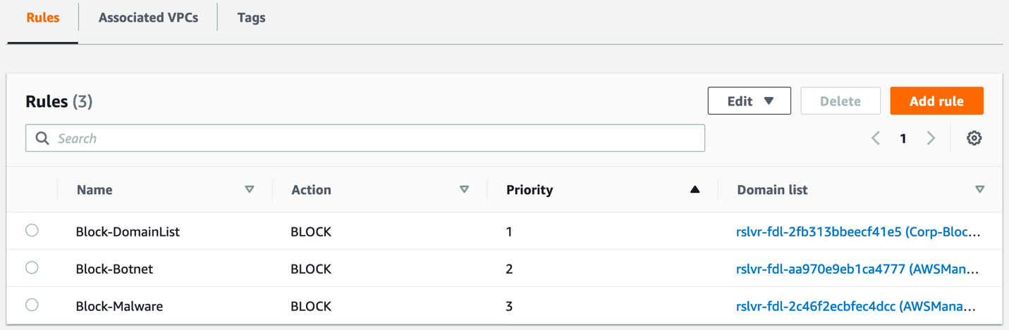
After the solution is in place, in order for the filtering to be effective, you need to create a rule group referencing the domain list and associate the rule group with some of your VPCs.

For cost information, see the AWS Pricing Calculator. This solution will be invoked 60 (minutes) * 24 (hours) * 30 (days) / 5 (minutes) = 8,640 times per month, invoking the Lambda function that will run for an average of 400 minutes, storing an average of 0.5 GB in Amazon S3, and creating a domain list that averages 1,500 domains. According to our public pricing, and without factoring in the AWS Free Tier, this will incur the estimated total cost of $1.43 per month for the filtering of 1 million DNS requests.

 
If you have feedback about this post, submit comments in the Comments section below. If you have questions about this post, contact AWS Support.

Want more AWS Security news? Follow us on Twitter.

Guillaume Neau

Guillaume Neau

Guillaume is a solutions architect of France with an expertise in information security that focus on building solutions that improve the life of citizens.

A multi-dimensional approach helps you proactively prepare for failures, Part 2: Infrastructure layer

Post Syndicated from Piyali Kamra original https://aws.amazon.com/blogs/architecture/a-multi-dimensional-approach-helps-you-proactively-prepare-for-failures-part-2-infrastructure-layer/

Distributed applications resiliency is a cumulative resiliency of applications, infrastructure, and operational processes. Part 1 of this series explored application layer resiliency. In Part 2, we discuss how using Amazon Web Services (AWS) managed services, redundancy, high availability, and infrastructure failover patterns based on recovery time and point objectives (RTO and RPO, respectively) can help in building more resilient infrastructures.

Pattern 1: Recognize high impact/likelihood infrastructure failures

To ensure cloud infrastructure resilience, we need to understand the likelihood and impact of various infrastructure failures, so we can mitigate them. Figure 1 illustrates that most of the failures with high likelihood happen because of operator error or poor deployments.

Automated testing, automated deployments, and solid design patterns can mitigate these failures. There could be datacenter failures—like whole rack failures—but deploying applications using auto scaling and multi-availability zone (multi-AZ) deployment, plus resilient AWS cloud native services, can mitigate the impact.

Likelihood and impact of failure events

Figure 1. Likelihood and impact of failure events

As demonstrated in the Figure 1, infrastructure resiliency is a combination of high availability (HA) and disaster recovery (DR). HA involves increasing the availability of the system by implementing redundancy among the application components and removing single points of failure.

Application layer decisions, like creating stateless applications, make it simpler to implement HA at the infrastructure layer by allowing it to scale using Auto Scaling groups and distributing the redundant applications across multiple AZs.

Pattern 2: Understanding and controlling infrastructure failures

Building a resilient infrastructure requires understanding which infrastructure failures are under control and which ones are not, as demonstrated in Figure 2.

These insights allow us to automate the detection of failures, control them, and employ pro-active patterns, such as static stability, to mitigate the need to scale up the infrastructure by over-provisioning it in advance.

Proactively designing systems in the event of failure

Figure 2. Proactively designing systems in the event of failure

The infrastructure decisions under our control that can increase the infrastructure resiliency of our system, include:

  • AWS services have control and data planes designed for minimum blast radius. Data planes typically have higher availability design goals than control planes and are usually less complex. When implementing recovery or mitigation responses to events that can affect resiliency, using control plane operations can lower the overall resiliency of your architectures. For example, Amazon Route 53 (Route 53) has a data plane designed for a 100% availability SLA. A good fail-over mechanism should rely on the data plane and not the control plane, as explained in Creating Disaster Recovery Mechanisms Using Amazon Route 53.
  • Understanding networking design and routes implemented in a virtual private cloud (VPC) are critical when testing the flow of traffic in our application. Understanding the flow of traffic helps us design better applications and see how one component failure can affect overall ingress/egress traffic. To achieve better network resiliency, it’s important to implement a good subnet strategy and manage our IP addresses to avoid fail-over issues and asymmetric routing in hybrid architectures. Use IP address management tools for established subnet strategies and routing decisions.
  • When designing VPCs and AZs, understanding the service limits, deploying independent routing tables and components in each zone increases availability. For example, highly available NAT gateways are preferred over NAT instances, as noted in the comparison provided in the Amazon VPC documentation.

Pattern 3: Considering different ways of increasing HA at the infrastructure layer

As already detailed, infrastructure resiliency = HA + DR.

Different ways by which system availability can be increased include:

  • Building for redundancy: Redundancy is the duplication of application components to increase the overall availability of the distributed system. After following application layer best practices, we can build auto healing mechanisms at the infrastructure layer.

We can take advantage of auto scaling features and use Amazon CloudWatch metrics and alarms to set up auto scaling triggers and deploy redundant copies of our applications across multiple AZs. This protects workloads from AZ failures, as shown in Figure 3.

Redundancy increases availability

Figure 3. Redundancy increases availability

  • Auto scale your infrastructure: When there are AZ failures, infrastructure auto scaling maintains the desired number of redundant components, which helps maintain the base level application throughput. This way, HA system and manage costs are maintained. Auto scaling uses metrics to scale in and out, appropriately, as shown in Figure 4.
How auto scaling improves availability

Figure 4. How auto scaling improves availability

  • Implement resilient network connectivity patterns: While building highly resilient distributed systems, network access to AWS infrastructure also needs to be highly resilient. While deploying hybrid applications, the capacity needed for hybrid applications to communicate with their cloud native application counterparts is an important consideration in designing the network access using AWS Direct Connect or VPNs.

Testing failover and fallback scenarios helps validate that network paths operate as expected and routes fail over as expected to meet RTO objectives. As the number of connection points between the data center and AWS VPCs increases, a hub and spoke configuration provided by the Direct Connect gateway and transit gateways simplify network topology, testing, and fail over. For more information, visit the AWS Direct Connect Resiliency Recommendations.

  • Whenever possible, use the AWS networking backbone to increase security, resiliency, and lower cost. AWS PrivateLink provides secure access to AWS services and exposes the application’s functionalities and APIs to other business units or partner accounts hosted on AWS.
  • Security appliances need to be set up in HA configuration, so that even if one AZ is unavailable, security inspection can be taken over by the redundant appliances in the other AZs.
  • Think ahead about DNS resolution: DNS is a critical infrastructure component; hybrid DNS resolution should be designed carefully with Route 53 HA inbound and outbound resolver endpoints instead of using self-managed proxies.

Implement a good strategy to share DNS resolver rules across AWS accounts and VPC’s with Resource Access Manager. Network failover tests are an important part of Disaster Recovery and Business Continuity Plans. To learn more, visit Set up integrated DNS resolution for hybrid networks in Amazon Route 53.

Additionally, ELB uses health checks to make sure that requests will route to another component if the underlying traffic application component fails. This improves the distributed system’s availability, as it is the cumulative availability of all different layers in our system. Figure 5 details advantages of some AWS managed services.

AWS managed services help in building resilient infrastructures (click the image to enlarge)

Figure 5. AWS managed services help in building resilient infrastructures (click the image to enlarge)

Pattern 4: Use RTO and RPO requirements to determine the correct failover strategy for your application

Capture RTO and RPO requirements early on to determine solid failover strategies (Figure 6). Disaster recovery strategies within AWS range from low cost and complexity (like backup and restore), to more complex strategies when lower values of RTO and RPO are required.

In pilot light and warm standby, only the primary region receives traffic. Pilot light only critical infrastructure components run in the backup region. Automation is used to check failures in the primary region using health checks and other metrics.

When health checks fail, use a combination of auto scaling groups, automation, and Infrastructure as Code (IaC) for quick deployment of other infrastructure components.

Note: This strategy depends on control plane availability in the secondary region for deploying the resources; keep this point in mind if you don’t have compute pre-provisioned in the secondary region. Carefully consider the business requirements and a distributed system’s application-level characteristics before deciding on a failover strategy. To understand all the factors and complexities involved in each of these disaster recovery strategies refer to disaster recovery options in the cloud.

Relationship between RTO, RPO, cost, data loss, and length of service interruption

Figure 6. Relationship between RTO, RPO, cost, data loss, and length of service interruption

Conclusion

In Part 2 of this series, we discovered that infrastructure resiliency is a combination of HA and DR. It is important to consider likelihood and impact of different failure events on availability requirements. Building in application layer resiliency patterns (Part 1 of this series), along with early discovery of the RTO/RPO requirements, as well as operational and process resiliency of an organization helps in choosing the right managed services and putting in place the appropriate failover strategies for distributed systems.

It’s important to differentiate between normal and abnormal load threshold for applications in order to put automation, alerts, and alarms in place. This allows us to auto scale our infrastructure for normal expected load, plus implement corrective action and automation to root out issues in case of abnormal load. Use IaC for quick failover and test failover processes.

Stay tuned for Part 3, in which we discuss operational resiliency!

How Munich Re Automation Solutions Ltd built a digital insurance platform on AWS

Post Syndicated from Sid Singh original https://aws.amazon.com/blogs/architecture/how-munich-re-automation-solutions-ltd-built-a-digital-insurance-platform-on-aws/

Underwriting for life insurance can be quite manual and often time-intensive with lots of re-keying by advisers before underwriting decisions can be made and policies finally issued. In the digital age, people purchasing life insurance want self-service interactions with their prospective insurer. People want speed of transaction with time to cover reduced from days to minutes. While this has been achieved in the general insurance space with online car and home insurance journeys, this is not always the case in the life insurance space. This is where Munich Re Automation Solutions Ltd (MRAS) offers its customers, a competitive edge to shrink the quote-to-fulfilment process using their ALLFINANZ solution.

ALLFINANZ is a cloud-based life insurance and analytics solution to underwrite new life insurance business. It is designed to transform the end consumer’s journey, delivering everything they need to become a policyholder. The core digital services offered to all ALLFINANZ customers include Rulebook Hub, Risk Assessment Interview delivery, Decision Engine, deep analytics (including predictive modeling capabilities), and technical integration services—for example, API integration and SSO integration.

Current state architecture

The ALLFINANZ application began as a traditional three-tier architecture deployed within a datacenter. As MRAS migrated their workload to the AWS cloud, they looked at their regulatory requirements and the technology stack, and decided on the silo model of the multi-tenant SaaS system. Each tenant is provided a dedicated Amazon Virtual Private Cloud (VPC) that holds network and application components, fully isolated from other primary insurers.

As an entry point into the ALLFINANZ environment, MRAS uses Amazon Route 53 to route incoming traffic to the appropriate Amazon VPC. The routing relies on a model where subdomains are assigned to each tenant, for example the subdomain allfinanz.tenant1.munichre.cloud is the subdomain for tenant 1. The diagram below shows the ALLFINANZ architecture. Note: not all links between components are shown here for simplicity.

Current high-level solution architecture for the ALLFINANZ solution

Figure 1. Current high-level solution architecture for the ALLFINANZ solution

  1. The solution uses Route 53 as the DNS service, which provides two entry points to the SaaS solution for MRAS customers:
    • The URL allfinanz.<tenant-id>.munichre.cloud allows user access to the ALLFINANZ Interview Screen (AIS). The AIS can exist as a standalone application, or can be integrated with a customer’s wider digital point-of -sale process.
    • The URL api.allfinanz.<tenant-id>.munichre.cloud is used for accessing the application’s Web services and REST APIs.
  2. Traffic from both entry points flows through the load balancers. While HTTP/S traffic from the application user access entry point flows through an Application Load Balancer (ALB), TCP traffic from the REST API clients flows through a Network Load Balancer (NLB). Transport Layer Security (TLS) termination for user traffic happens at the ALB using certificates provided by the AWS Certificate Manager.  Secure communication over the public network is enforced through TLS validation of the server’s identity.
  3. Unlike application user access traffic, REST API clients use mutual TLS authentication to authenticate a customer’s server. Since NLB doesn’t support mutual TLS, MRAS opted for a solution to pass this traffic to a backend NGINX server for the TLS termination. Mutual TLS is enforced by using self-signed client and server certificates issued by a certificate authority that both the client and the server trust.
  4. Authenticated traffic from ALB and NGINX servers is routed to EC2 instances hosting the application logic. These EC2 instances are hosted in an auto-scaling group spanning two Availability Zones (AZs) to provide high availability and elasticity, therefore, allowing the application to scale to meet fluctuating demand.
  5. Application transactions are persisted in the backend Amazon Relational Database Service MySQL instances. This database layer is configured across multi-AZs, providing high availability and automatic failover.
  6. The application requires the capability to integrate evidence from data sources external to the ALLFINANZ service. This message sharing is enabled through the Amazon MQ managed message broker service for Apache Active MQ.
  7. Amazon CloudWatch is used for end-to-end platform monitoring through logs collection and application and infrastructure metrics and alerts to support ongoing visibility of the health of the application.
  8. Software deployment and associated infrastructure provisioning is automated through infrastructure as code using a combination of Git, Amazon CodeCommit, Ansible, and Terraform.
  9. Amazon GuardDuty continuously monitors the application for malicious activity and delivers detailed security findings for visibility and remediation. GuardDuty also allows MRAS to provide evidence of the application’s strong security posture to meet audit and regulatory requirements.

High availability, resiliency, and security

MRAS deploys their solution across multiple AWS AZs to meet high-availability requirements and ensure operational resiliency. If one AZ has an ongoing event, the solution will remain operational, as there are instances receiving production traffic in another AZ. As described above, this is achieved using ALBs and NLBs to distribute requests to the application subnets across AZs.

The ALLFINANZ solution uses private subnets to segregate core application components and the database storage platform. Security groups provide networking security measures at the elastic network interface level. MRAS restrict access from incoming connection requests to ranges of IP addresses by attaching security groups to the ALBs. Amazon Inspector monitors workloads for software vulnerabilities and unintended network exposure. AWS WAF is integrated with the ALB to protect from SQL injection or cross-site scripting attacks on the application.

Optimizing the existing workload

One of the key benefits of this architecture is that now MRAS can standardize the infrastructure configuration and ensure consistent versioning of the workload across tenants. This makes onboarding new tenants as simple as provisioning another VPC with the same infrastructure footprint.

MRAS are continuing to optimize their architecture iteratively, examining components to modernize to cloud-native components and evolving towards the pool model of multi-tenant SaaS architecture wherever possible. For example, MRAS centralized their per-tenant NAT gateway deployment to a centralized outbound Internet routing design using AWS Transit Gateway, saving approximately 30% on their overall NAT gateway spend.

Conclusion

The AWS global infrastructure has allowed MRAS to serve more than 40 customers in five AWS regions around the world. This solution improves customers’ experience and workload maintainability by standardizing and automating the infrastructure and workload configuration within a SaaS model, compared with multiple versions for the on-premise deployments. SaaS customers are also freed up from the undifferentiated heavy lifting of infrastructure operations, allowing them to focus on their business of underwriting for life insurance.

MRAS used the AWS Well-Architected Framework to assess their architecture and list key recommendations. AWS also offers Well-Architected SaaS Lens and AWS SaaS Factory Program, with a collection of resources to empower and enable insurers at any stage of their SaaS on AWS journey.

Automatically block suspicious DNS activity with Amazon GuardDuty and Route 53 Resolver DNS Firewall

Post Syndicated from Akshay Karanth original https://aws.amazon.com/blogs/security/automatically-block-suspicious-dns-activity-with-amazon-guardduty-and-route-53-resolver-dns-firewall/

In this blog post, we’ll show you how to use Amazon Route 53 Resolver DNS Firewall to automatically respond to suspicious DNS queries that are detected by Amazon GuardDuty within your Amazon Web Services (AWS) environment.

The Security Pillar of the AWS Well-Architected Framework includes incident response, stating that your organization should implement mechanisms to automatically respond to and mitigate the potential impact of security issues. Automating incident response helps you scale your capabilities, rapidly reduce the scope of compromised resources, and reduce repetitive work by security teams.

Use cases for Route 53 Resolver DNS Firewall

Route 53 Resolver DNS Firewall is a managed firewall that you can use to block DNS queries that are made for known malicious domains and to allow queries for trusted domains. It provides more granular control over the DNS querying behavior of resources within your VPCs.

Let’s discuss two use cases for Route 53 Resolver DNS Firewall:

Use of allow lists – If you have stricter security requirements around network security controls and want to deny all outbound DNS queries for domains that don’t match those on your lists of approved domains (known as allow lists), you can create such rules. This is called a walled garden approach to DNS security. These allow lists only include the domains for which resources within your Amazon Virtual Private Cloud (Amazon VPC) are allowed to make DNS queries through Amazon-provided DNS. This helps to ensure that the DNS queries containing the domains that your organization doesn’t trust are blocked.

Use of deny lists – If your organization prefers to allow all outbound DNS lookups within your accounts by default and only requires the ability to block DNS queries for known malicious domains, you can use DNS Firewall to create deny lists, which include all the malicious domain names that your organization is aware of. DNS Firewall also provides AWS Managed Rules, giving you to the ability to configure protections against known DNS threats like command-and-control (C&C) bots. You can also add block lists from open-source third-party threat intelligence sources.

A few important points about the use of allow and deny lists:

  1. Broader use of allow lists is more effective at blocking a greater number of malicious DNS queries than a short deny list. For example, if your workloads only need access to .com domains, then allowing only .com will block many malicious domains that might be specific to certain countries. View a list of country code top-level domains (ccTLDs).
  2. If you use allow lists, you need to make sure that you keep up with the domains that your applications need to communicate with. Likewise, if you use deny lists, you need to keep up with updates to the lists.
  3. Allow lists and deny lists are not mutually exclusive models and can be used together. For example, let’s say that you have an allow list that only allows .com domains (with the intention of blocking several ccTLDs by default). You can also use the built-in AWS Managed Rules deny list to block known malicious .com domains for an additional layer of security.

Solution overview

Refer to the DNS Firewall documentation to familiarize yourself with its constructs and understand how it works. The automation example we provide in this blog post is focused on providing blocks or alerts for DNS queries with suspicious domain names. For example, consider the scenario where an Amazon Elastic Compute Cloud (Amazon EC2) instance queries a domain name that is associated with a known command-and-control server. As shown in Figure 1, when GuardDuty detects communication with the malicious domain, it initiates a series of steps. First, AWS Step Functions orchestrates the remediation response through a defined workflow, then DNS Firewall adds the suspicious domain to deny list or alert list, and finally GuardDuty notifies the security operators of the attempted communication.

Figure 1: High-level solution overview

Figure 1: High-level solution overview

In this solution, the detection of threats by GuardDuty triggers the automated remediation procedure documented in this post. GuardDuty informs you of the status of your AWS environment by producing security findings. Each GuardDuty finding has an assigned severity level and value that reflects the potential risk that the finding could have to your network as determined by our security engineers. The value of the severity can fall anywhere within the 0.1 to 8.9 range, with higher values indicating greater security risk. To help you determine a response to a potential security issue that is highlighted by a finding, GuardDuty breaks down this range into High, Medium, and Low severity levels. We have seen that many of the DNS-based GuardDuty findings fall into the category of High severity, and many times these findings are strongly indicative of potential compromise (for example, pre ransomware activity).

In this blog post, we specifically focus on the following types of GuardDuty findings:

  • Backdoor:EC2/C&CActivity.B!DNS
  • Impact:EC2/MaliciousDomainRequest.Reputation
  • Trojan:EC2/DNSDataExfiltration

We’ve configured DNS Firewall to block only events with High severity by sending only those domains to the deny list. DNS Firewall sends the rest of the domains to an alert list.

This solution uses Step Functions and AWS Lambda so that incident response steps run in the correct order. Step Functions also provides retry and error-handling logic. Lambda functions interact with networking services to block traffic, and with databases to store data about blocked domain lists and AWS Security Hub finding Amazon Resource Names (ARNs).

How it works

Figure 2 shows the automated remediation workflow in detail.
 

Figure 2: Detailed workflow diagram

Figure 2: Detailed workflow diagram

The solution is implemented as follows:

  1. GuardDuty detects communication attempts that include a suspicious domain. GuardDuty generates a finding, in JSON format, that includes details such as the EC2 instance ID involved (if applicable), account information, type of finding, domain, and other details. Following is a sample finding (some fields removed for brevity).
    {
      "schemaVersion": "2.0",
      "accountId": "123456789012",
      "id": " 1234567890abcdef0",
      "type": "Backdoor:EC2/C&CActivity.B!DNS",
      "service": {
        "serviceName": "guardduty",
        "action": {
          "actionType": "DNS_REQUEST",
         "dnsRequestAction": {
    "domain": "guarddutyc2activityb.com",
    "protocol": "UDP",
    "blocked": false
          }
        }
      }
    }
    

  2. Security Hub ingests the finding generated by GuardDuty and consolidates it with findings from other AWS security services. Security Hub also publishes the contents of the finding to the default bus in Amazon EventBridge. Following is a snippet from a sample event published to EventBridge.
    { 
      "id": "12345abc-ca56-771b-cd1b-710550598e37", 
      "detail-type": "Security Hub Findings - Imported", 
      "source": "aws.securityhub", 
      "account": "123456789012", 
      "time": "2021-01-05T01:20:33Z", 
      "region": "us-east-1", 
      "detail": { 
        "findings": [ 
            { "ProductArn": "arn:aws:securityhub:us-east-1::product/aws/guardduty", 
            "Types": ["Software and Configuration Checks/Backdoor:EC2.C&CActivity.B!DNS"], 
            "LastObservedAt": "2021-01-05T01:15:01.549Z", 
            "ProductFields": 
                {"aws/guardduty/service/action/dnsRequestAction/blocked": "false",
                "aws/guardduty/service/action/dnsRequestAction/domain": "guarddutyc2activityb.com"} 
                }
                ]}}
    

  3. EventBridge has a rule with an event pattern that matches GuardDuty events that contain the malicious domain name. When an event matching the pattern is published on the default bus, EventBridge routes that event to the designated target, in this case a Step Functions state machine. Following is a snippet of AWS CloudFormation code that defines the EventBridge rule.
    # EventBridge Event Rule - For Security Hub event published to EventBridge:
      SecurityHubtoFirewallStateMachineEvent:
        Type: "AWS::Events::Rule"
        Properties:
          Description: "Security Hub - GuardDuty findings with DNS Domain"
          EventPattern:
            source:
            - aws.securityhub
            detail:
              findings:
                ProductFields:
                  aws/guardduty/service/action/dnsRequestAction/blocked:
                    - "exists": true
          State: "ENABLED"
          Targets:
            -
              Arn: !GetAtt SecurityHubtoDnsFirewallStateMachine.Arn
              RoleArn: !GetAtt SecurityHubtoFirewallStateMachineEventRole.Arn
              Id: "GuardDutyEvent-StepFunctions-Trigger"
    

  4. The Step Functions state machine ingests the details of the Security Hub finding published in EventBridge and orchestrates the remediation response through a defined workflow. Figure 3 shows the state machine workflow.
     
    Figure 3: AWS Step Functions state machine workflow

    Figure 3: AWS Step Functions state machine workflow

  5. The first two steps in the state machine, getDomainFromDynamo and isDomainInDynamo, invoke the Lambda function CheckDomainInDynamoLambdaFunction that checks whether the flagged domain is already in the Amazon DynamoDB table. If the domain already exists in DynamoDB, then the workflow continues to check whether the domain is also in the domain list and adds it accordingly. If the domain is not in DynamoDB, then the workflow considers it a new addition and adds the domain to both domain lists, as well as the DynamoDB table.
  6. The next three steps in the state machine—getDomainFromDomainList, isDomainInDomainList, and addDomainToDnsFirewallDomainList—invoke a second Lambda function that checks and updates the DNS Firewall domain lists with the domain name. Figure 4 shows an example of the DNS Firewall rules and associated domain list.
     
    Figure 4: Sample rules in a DNS Firewall rule group

    Figure 4: Sample rules in a DNS Firewall rule group

    Figure 5 shows the domain lists.
     

    Figure 5: Domain lists

    Figure 5: Domain lists

    The next step in the state machine, updateDynamoDB, invokes a third Lambda function that updates the DynamoDB table with the domain that was just added to the domain list. Figure 6 shows an example domain entry that gets stored inside the DynamoDB table.
     

    Figure 6: DynamoDB table entry

    Figure 6: DynamoDB table entry

  7. The notifySuccess step of the state machine uses an Amazon Simple Notification Service (Amazon SNS) topic to send out a message that the automatic block or alert happened.
  8. If there was a failure in any of the previous steps, then the state machine runs the notifyFailure step. The state machine publishes a message on the SNS topic that the automated remediation workflow has failed to complete, and that manual intervention might be required.

Solution deployment and testing

To set up this solution, you’ll do the following steps:

  1. Verify prerequisites in your AWS account.
  2. Deploy the CloudFormation template.
  3. Create a test Security Hub event.
  4. Confirm the entry in the DNS Firewall rule group domain list.
  5. Confirm the SNS notification.
  6. Apply the rule group to your VPC by using DNS Firewall.

Step 1: Verify prerequisites in your AWS account

The sample solution we provide in this blog post requires that you activate both GuardDuty and Security Hub in your AWS account. If either of these services is not activated in your account, do the following:

Step 2: Deploy the CloudFormation template

For this next step, make sure that you deploy the template within the AWS account and the AWS Region where you want to monitor GuardDuty findings and block suspicious DNS activity. Depending on your architecture, you can deploy the solution one time centrally in a security account or deploy it repeatedly across multiple accounts.

To deploy the template

  1. Choose the Launch Stack button to launch a CloudFormation stack in your account:
    Select the Launch Stack button to launch the template

    Note: The stack will launch in the N. Virginia (us-east-1) Region. It takes approximately 15 minutes for the CloudFormation stack to complete. To deploy this solution into other AWS Regions, download the solution’s CloudFormation template and deploy it to the selected Region. Network Firewall isn’t currently available in all Regions. For more information about where it’s available, see the list of service endpoints.

  2. In the AWS CloudFormation console, select the Select Template form, and then choose Next.
  3. On the Specify Details page, provide the following input parameters. You can modify the default values to customize the solution for your environment.
    • AdminEmail – The email address to receive notifications. This must be a valid email address. There is no default value.
    • DnsFireWallAlertDomainListName – The name of the domain list for DNS Firewall that consists of domains that will be only alerted and not blocked. The default value is DemoAlertDomainListAutoUpdated.
    • DnsFireWallBlockDomainListName – The name of the domain list for DNS Firewall that consists of domains that will be blocked. The default value is DemoBlockedDomainListAutoUpdated.
    • DnsFirewallBlockAction – You can select NODATA or NXDOMAIN. NODATA implies that there is no response available if a DNS query from the VPC matches a domain in the block domain list. NXDOMAIN implies that the response is an error message, which indicates that a domain doesn’t exist. The default value is NODATA.

    Figure 7 shows an example of the values entered in the Parameters screen.

    Figure 7: Sample CloudFormation stack parameters

    Figure 7: Sample CloudFormation stack parameters

  4. After you’ve entered values for all of the input parameters, choose Next.
  5. On the Options page, keep the defaults, and then choose Next.
  6. On the Review page, in the Capabilities section, select the check box next to I acknowledge that AWS CloudFormation might create IAM resources. Then choose Create. Figure 8 shows what the CloudFormation capabilities acknowledgement prompt looks like.
     
    Figure 8: AWS CloudFormation capabilities acknowledgement

    Figure 8: AWS CloudFormation capabilities acknowledgement

While the stack is being created, check the email inbox that corresponds to the value that you gave for the AdminEmail address parameter. Look for an email message with the subject “AWS Notification – Subscription Confirmation.” Choose the link to confirm the subscription to the SNS topic.

After the Status field for the CloudFormation stack changes to CREATE_COMPLETE, as shown in Figure 9, the solution is implemented and is ready for testing.
 

Figure 9: CloudFormation stack completed deployment

Figure 9: CloudFormation stack completed deployment

Step 3: Create a test Security Hub event

After the CloudFormation stack has completed deployment, you can test the functionality by creating a test event in the same format as would be published by Security Hub.

To create a test run of the solution

  1. In the AWS Management Console, choose Services, choose CloudFormation, and then for Stack, choose the stack name that you provided in Step 2: Deploy the CloudFormation template.
  2. In the Resources tab for the stack, look for the SecurityHubDnsFirewallStateMachine entry. It should appear as shown in Figure 10.
     
    Figure 10: CloudFormation stack resources

    Figure 10: CloudFormation stack resources

  3. Choose the link in the entry. You’ll be redirected to the Step Functions console, with the state machine already open. Choose Start execution.
     
    Figure 11: AWS Step Functions state machine

    Figure 11: AWS Step Functions state machine

  4. To facilitate testing, we’ve provided a test event file. On the Start execution page, in the Input section, paste the C&CActivity.B!DNS finding sample as shown in Figure 12.
     
    Figure 12: Sample input for the Step Functions state machine execution

    Figure 12: Sample input for the Step Functions state machine execution

  5. Note the domain name guarddutyc2activityb.com for the remote host identified in the GuardDuty finding in the test event on line 57 of the sample. The solution should block or alert traffic from that domain name in the following steps.
  6. Choose Start execution to begin the processing of the test event.
  7. You can now track the state machine processing of the test event. The processing should complete within a few seconds. You can select different steps in the visual Graph inspector to view input and output data. Figure 13 shows the input to the addDomainToDnsFirewallDomainList step that launches a Lambda function that interacts with DNS Firewall.
     
    Figure 13: Step Functions state machine step details

    Figure 13: Step Functions state machine step details

Step 4: Confirm the entry in the DNS Firewall rule group

Now that a test event was processed by the state machine, you can check whether the DNS Firewall rule group would block traffic to the domain name identified in the GuardDuty finding.

To validate entries in the DNS Firewall rule group

  1. In the AWS Management Console, choose Services, and then choose VPC. In the DNS Firewall section in the left navigation bar, choose DNS Firewall rule groups.
  2. Choose the demoDnsFirewallRuleGroup rule group created by the solution, and you’ll be able to see the rules as shown in Figure 14.
     
    Figure 14: Select the DNS Firewall rule

    Figure 14: Select the DNS Firewall rule

  3. Choose the domain list associated with the BLOCK rule. Confirm that the rules blocking the traffic from the source and to the domain that you specified in the test event were created. The domain list should look similar to what is shown in Figure 15.
     
    Figure 15: Verify that the domain was added to the blocked domain list

    Figure 15: Verify that the domain was added to the blocked domain list

Step 5: Confirm the SNS notification

In this step, you’ll view the SNS notification that was sent to the email address you set up.

To confirm the SNS notification

  • Review the email inbox for the value that you provided for the AdminEmail parameter and look for a message with the subject line “AWS Notification Message.” The contents of the message from SNS should be similar to the following.
    {"Blocked":"true","Input":{"ResponseMetadata":{"RequestId":"HOLOAAENUS3MN9B0DS6CO8BF4BVV4KQNSO5AEMVJF66Q9ASUAAJG","HTTPStatusCode":200,"HTTPHeaders":{"server":"Server","date":"Wed, 17 Nov 2021 08:20:38 GMT","content-type":"application/x-amz-json-1.0","content-length":"2","connection":"keep-alive","x-amzn-requestid":"HOLOAAENUS3MN9B0DS6CO8BF4BVV4KQNSO5AEMVJF66Q9ASUAAJG","x-amz-crc32":"2745614147"},"RetryAttempts":0}}}
    

Step 6: Apply the rule group to your VPC by using DNS Firewall

As part of the CloudFormation template deployment, two test VPCs have been created for you, to demonstrate that you can assign a single DNS Firewall rule group to multiple VPCs. You can also associate this rule group to your existing VPC of interest. To learn how to do this task, see Managing associations between your VPC and Route 53 Resolver DNS Firewall rule group. For visibility into DNS queries and for debugging purposes, the template creates log groups that accumulate DNS Resolver query logs.

After you’ve successfully tested the given sample that emulates C&CActivity.B!DNS, you can repeat steps 3 to 6 for the MaliciousDomainRequest.Reputation finding sample and the DNSDataExfiltration finding sample.

These samples are supplied for your convenience, and you will see the blocking action in a matter of minutes. Alternatively, you can use other ways to test, which might need about an hour for blocking action to happen. To initiate DNS C&C activity, you can make a DNS request from your instance (using dig for Linux or nslookup for Windows) against the test domain guarddutyc2activityb.com. Alternatively, you can use GuardDuty Tester, which generates DNS C&C activity and DNS exfiltration unauthorized events.

To take this solution one step further, you can implement automatic aging out of the domains that get added to the domain list. One way to do this is to use the Time to Live feature in DynamoDB and keep repopulating the domain list from DynamoDB at regular intervals of time. The benefit of this is that if the malicious nature of a domain in the domain list changes over time, the list will be kept up to date during this age out and repopulation process.

Considerations

There are a few considerations that you should keep in mind regarding DNS Firewall:

  • DNS Firewall and AWS Network Firewall work together for improved domain-filtering capability across HTTP(S) traffic. A domain list that you configure in Network Firewall should reflect the domain list configured in DNS Firewall.
  • DNS Firewall filters based on the domain name. It doesn’t translate that domain name to an IP address to be blocked.
  • It’s a best practice to block outbound traffic to port 53 with network access control lists (network ACLs) or Network Firewall so that GuardDuty can monitor DNS queries.
  • DNS Firewall filters DNS queries to the Amazon Route 53 Resolver (also known as AmazonProvidedDNS or VPC .2 Resolver) in the VPC. So for traffic leaving the VPC, we recommend that you use DNS Firewall along with Network Firewall, which you can use to secure traffic that isn’t headed to Amazon Route 53 Resolver. Network Firewall can also block domain names that exist in network traffic leaving the Amazon VPC, such as in HTTP HOST headers, TLS Server Name Indication (SNI) fields, and so on.
  • You can use Network Firewall to block external encrypted DNS services so that these services can’t be used to circumvent your DNS Firewall policies.

Conclusion

In this blog post, you learned how to automatically block malicious domains by using Route 53 Resolver DNS Firewall and GuardDuty. You can use this sample solution to automatically block communication to suspicious hosts discovered by GuardDuty, and you can apply those blocks across all configured DNS Firewall firewalls within your account.

All of the code for this solution is available on GitHub. Feel free to play around with the code; we hope it helps you learn more about automated security remediation. You can adjust the code to better fit your unique environment or extend the code with additional steps.

If you have comments about this blog post, submit them in the Comments section below. If you have questions about using this solution, start a thread in the Route 53 Resolver forum or GuardDuty forums, or contact AWS Support.

Want more AWS Security how-to content, news, and feature announcements? Follow us on Twitter.

Author

Akshay Karanth

Akshay is a senior solutions architect at AWS. He helps digital native businesses learn, build, and grow in the AWS Cloud. Before AWS, he worked at companies such as Juniper Networks and Microsoft in various customer facing roles across networking and security domains. When not at work, Akshay enjoys hiking up a hard trail or cooking a fulfilling meal with his family.

Author

Rohit Aswani

Rohit is a specialist solutions architect focussed on Networking at AWS, where he helps customers build and design scalable, highly-available, secure, resilient, and cost-effective networks. He holds an MS in telecommunication systems management from Northeastern University, specializing in computer networking.

Contributor

Special thanks to Fabrice Dall’ara who made significant contributions to this post.

Disaster recovery with AWS managed services, Part 2: Multi-Region/backup and restore

Post Syndicated from Dhruv Bakshi original https://aws.amazon.com/blogs/architecture/disaster-recovery-with-aws-managed-services-part-ii-multi-region-backup-and-restore/

In part I of this series, we introduced a disaster recovery (DR) concept that uses managed services through a single AWS Region strategy. In part two, we introduce a multi-Region backup and restore approach. With this approach, you can deploy a DR solution in multiple Regions, but it will be associated with longer RPO/RTO. Using a backup and restore strategy will safeguard applications and data against large-scale events as a cost-effective solution, but will result in longer downtimes and greater loss of data in the event of a disaster as compared to other strategies as shown in Figure 1.

DR Strategies

Figure 1. DR Strategies

Implementing the multi-Region/backup and restore strategy

Using multiple Regions ensures resiliency in the most serious, widespread outages. A secondary Region protects workloads against being unable to run within a given Region, because they are wide and geographically dispersed.

Architecture overview

The application diagram presented in Figures 2.1 and 2.2 refers to an application that processes payment transactions, which was modernized to utilize managed services in the AWS Cloud. In this post, we’ll show you which AWS services it uses and how they work to maintain multi-Region/backup and restore strategy.

These figures show how to successfully implement the backup and restore strategy and successfully fail over your workload. The following sections list the components of the example application presented in the figures, which works as follows:

Multi-Region backup

Figure 2.1. Multi-Region backup

Multi-Region restore

Figure 2.2. Multi-Region restore

Route 53

Route 53 health checks monitor the health and performance of your web applications, web servers, and other resources. Health checks are necessary for configuring DNS failover within Route 53. Once an application or resource becomes unhealthy, you’ll need to initiate a manual failover process to create resources in the secondary Region. In our architecture, we use CloudWatch alarms to automate notifications of changes in health status.

Please check out the Creating Disaster Recovery Mechanisms Using Amazon Route 53 blog post for additional DR mechanisms using Amazon Route 53.

Amazon EKS control plane

Amazon Elastic Kubernetes Service (Amazon EKS) automatically scales control plane instances based on load, automatically detects and replaces unhealthy control plane instances, and restarts them across the Availability Zones within the Region as needed. Because on-demand clusters are provisioned in the secondary Region, AWS also manages the control plane the same way.

Amazon EKS data plane

It is a best practice to create worker nodes using Amazon Elastic Compute Cloud (Amazon EC2) Auto Scaling groups instead of creating individual EC2 instances and joining them to the cluster. This is because Amazon EC2 Auto Scaling groups automatically replace any terminated or failed nodes, which ensures that the cluster always has the capacity to run your workload.

The Amazon EKS control plane and data plane will be created on demand in the secondary Region during an outage via Infrastructure-as-a-Code (IaaC) such as AWS CloudFormation, Terraform, etc. You should pre-stage all networking requirements like virtual private cloud (VPC), subnets, route tables, gateways and deploy the Amazon EKS cluster during an outage in the primary Region.

As shown in the Backup and restore your Amazon EKS cluster resources using Velero blog post, you may use a third-party tool like Velero for managing snapshots of persistent volumes. These snapshots can be stored in an Amazon Simple Storage Service (Amazon S3) bucket in the primary Region, which will be replicated to an S3 bucket in another Region via cross-Region replication.

During an outage in the primary Region, you can use the tool in the secondary Region to restore volumes from snapshots in the standby cluster.

OpenSearch Service

For domains running Amazon OpenSearch Service, OpenSearch Service takes hourly automated snapshots and retains up to 336 for 14 days. These snapshots can only be used for cluster recovery within the same Region as the primary OpenSearch cluster.

You can use OpenSearch APIs to create a manual snapshot of an OpenSearch cluster, which can be stored in a registered repository like Amazon S3. You can do this manually or create a scheduled Lambda function based on their RPO, which prompts creation of a manual snapshot that will be stored in an S3 bucket. Amazon S3 cross-Region replication will then automatically and asynchronously copy objects across S3 buckets.

You can restore OpenSearch Service clusters by creating the cluster on demand via CloudFormation and using OpenSearch APIs to restore the snapshot from an S3 bucket.

Amazon RDS Postgres

Amazon Relational Database Service (Amazon RDS) can copy continuous backups cross-Region. You can configure your Amazon RDS database instance to replicate snapshots and transaction logs to a destination Region of your choice.

If a continuous backup rule also specifies a cross-account or cross-Region copy, AWS Backup takes a snapshot of the continuous backup, copies that snapshot to the destination vault, and then deletes the source snapshot. For continuous backup of Amazon RDS, AWS Backup creates a snapshot every 24 hours and stores transaction logs every 5 minutes in-Region. The Backup Frequency setting only applies to cross-Region backups of these continuous backups. Backup Frequency determines how often AWS Backup:

  • Creates a snapshot at that point in time from the existing snapshot plus all transaction logs up to that point
  • Copies snapshots to the other Region(s)
  • Deletes snapshots (because it only was created to be copied)

For more information, refer to the Point-in-time recovery and continuous backup for Amazon RDS with AWS Backup blog post.

ElastiCache

You can export and import backup and copy API calls for Amazon ElastiCache to develop a snapshot and restore strategy in a secondary Region. You can either prompt a manual backup and copy of that backup to S3 bucket or create a pair of Lambda functions to run at a schedule to meet the RPO requirements. The Lambda functions will prompt a manual backup, which creates a .rdb to an S3 bucket. Amazon S3 cross-Region replication will then handle asynchronous copy of the backup to an S3 bucket in a secondary Region.

You can use CloudFormation to create an ElastiCache cluster on demand and use CloudFormation properties such as SnapshotArns and SnapshotName to point to the desired ElastiCache backup stored in Amazon S3 to seed the cluster in the secondary Region.

Amazon Redshift

Amazon Redshift takes automatic, incremental snapshots of your data periodically and saves them to Amazon S3. Additionally, you can take manual snapshots of your data whenever you want.

To precisely control when snapshots are taken, you can create a snapshot schedule and attach it to one or more clusters. You can also configure cross-Region snapshot copy, which will automatically copy all your automated and manual snapshots to another Region.

During an outage, you can create the Amazon Redshift cluster on demand via CloudFormation and use CloudFormation properties such as SnapshotIdentifier to restore the new cluster from that snapshot.

Note: You can add an additional layer of protection to your backups through AWS Backup Vault Lock, S3 Object Lock, and Encrypted Backups.

Conclusion

With greater adoption of managed services within the cloud, there is a need to think of creative ways to implement a cost-effective DR solution. This backup and restore approach offered in this post will lower costs through more lenient RPO/RTO requirements, while providing a solution to utilize AWS managed services.

In the next post, we will discuss a multi-Region active/active strategy for the same application stack illustrated in this post.

Other posts in this series

Related information

Looking for more architecture content? AWS Architecture Center provides reference architecture diagrams, vetted architecture solutions, Well-Architected best practices, patterns, icons, and more!

Running hybrid Active Directory service with AWS Managed Microsoft Active Directory

Post Syndicated from Lewis Tang original https://aws.amazon.com/blogs/architecture/running-hybrid-active-directory-service-with-aws-managed-microsoft-active-directory/

Enterprise customers often need to architect a hybrid Active Directory solution to support running applications in the existing on-premises corporate data centers and AWS cloud. There are many reasons for this, such as maintaining the integration with on-premises legacy applications, keeping the control of infrastructure resources, and meeting with specific industry compliance requirements.

To extend on-premises Active Directory environments to AWS, some customers choose to deploy Active Directory service on self-managed Amazon Elastic Compute Cloud (EC2) instances after setting up connectivity for both environments. This setup works fine, but it also presents management and operations challenges when it comes to EC2 instance operation management, Windows operating system, and Active Directory service patching and backup. This is where AWS Directory Service for Microsoft Active Directory (AWS Managed Microsoft AD) helps.

Benefits of using AWS Managed Microsoft AD

With AWS Managed Microsoft AD, you can launch an AWS-managed directory in the cloud, leveraging the scalability and high availability of an enterprise directory service while adding seamless integration into other AWS services.

In addition, you can still access AWS Managed Microsoft AD using existing administrative tools and techniques, such as delegating administrative permissions to select groups in your organization. The full list of permissions that can be delegated is described in the AWS Directory Service Administration Guide.

Active Directory service design consideration with a single AWS account

Single region

A single AWS account is where the journey begins: a simple use case might be when you need to deploy a new solution in the cloud from scratch (Figure 1).

A single AWS account and single-region model

Figure 1. A single AWS account and single-region model

In a single AWS account and single-region model, the on-premises Active Directory has “company.com” domain configured in the on-premises data center. AWS Managed Microsoft AD is set up across two availability zones in the AWS region for high availability. It has a single domain, “na.company.com”, configured. The on-premises Active Directory is configured to trust the AWS Managed Microsoft AD with network connectivity via AWS Direct Connect or VPN. Applications that are Active-Directory–aware and run on EC2 instances have joined na.company.com domain, as do the selected AWS managed services (for example, Amazon Relational Database Service for SQL server).

Multi-region

As your cloud footprint expands to more AWS regions, you have two options also to expand AWS Managed Microsoft AD, depending on which edition of AWS Managed Microsoft AD is used (Figure 2):

  1. With AWS Managed Microsoft AD Enterprise Edition, you can turn on the multi-region replication feature to configure automatically inter-regional networking connectivity, deploy domain controllers, and replicate all the Active Directory data across multiple regions. This ensures that Active-Directory–aware workloads residing in those regions can connect to and use AWS Managed Microsoft AD with low latency and high performance.
  2. With AWS Managed Microsoft AD Standard Edition, you will need to add a domain by creating independent AWS Managed Microsoft AD directories per-region. In Figure 2, “eu.company.com” domain is added, and AWS Transit Gateway routes traffic among Active-Directory–aware applications within two AWS regions. The on-premises Active Directory is configured to trust the AWS Managed Microsoft AD, either by Direct Connect or VPN.
A single AWS account and multi-region model

Figure 2. A single AWS account and multi-region model

Active Directory Service Design consideration with multiple AWS accounts

Large organizations use multiple AWS accounts for administrative delegation and billing purposes. This is commonly implemented through AWS Control Tower service or AWS Control Tower landing zone solution.

Single region

You can share a single AWS Managed Microsoft AD with multiple AWS accounts within one AWS region. This capability makes it simpler and more cost-effective to manage Active-Directory–aware workloads from a single directory across accounts and Amazon Virtual Private Cloud (VPC). This option also allows you seamlessly join your EC2 instances for Windows to AWS Managed Microsoft AD.

As a best practice, place AWS Managed Microsoft AD in a separate AWS account, with limited administrator access but sharing the service with other AWS accounts. After sharing the service and configuring routing, Active Directory aware applications, such as Microsoft SharePoint, can seamlessly join Active Directory Domain Services and maintain control of all administrative tasks. Find more details on sharing AWS Managed Microsoft AD in the Share your AWS Managed AD directory tutorial.

Multi-region

With multiple AWS Accounts and multiple–AWS-regions model, we recommend using AWS Managed Microsoft AD Enterprise Edition. In Figure 3, AWS Managed Microsoft AD Enterprise Edition supports automating multi-region replication in all AWS regions where AWS Managed Microsoft AD is available. In AWS Managed Microsoft AD multi-region replication, Active-Directory–aware applications use the local directory for high performance but remain multi-region for high resiliency.

Multiple AWS accounts and multi-region model

Figure 3. Multiple AWS accounts and multi-region model

Domain Name System resolution design

To enable Active-Directory–aware applications communicate between your on-premises data centers and the AWS cloud, a reliable solution for Domain Name System (DNS) resolution is needed. You can set the Amazon VPC Dynamic Host Configuration Protocol (DHCP) option sets to either AWS Managed Microsoft AD or on-premises Active Directory; then, assign it to each VPC in which the required Active-Directory–aware applications reside. The full list of options working with DHCP option sets is described in Amazon Virtual Private Cloud User Guide.

The benefit of configuring DHCP option sets is to allow any EC2 instances in that VPC to resolve their domain names by pointing to the specified domain and DNS servers. This prevents the need for manual configuration of DNS on EC2 instances. However, because DHCP option sets cannot be shared across AWS accounts, this requires a DHCP option sets also to be created in additional accounts.

DHCP option sets

Figure 4. DHCP option sets

An alternative option is creating an Amazon Route 53 Resolver. This allows customers to leverage Amazon-provided DNS and Route 53 Resolver endpoints to forward a DNS query to the on-premises Active Directory or AWS Managed Microsoft AD. This is ideal for multi-account setups and customers desiring hub/spoke DNS management.

This alternative solution replaces the need to create and manage EC2 instances running as DNS forwarders with a managed and scalable solution, as Route 53 Resolver forwarding rules can be shared with other AWS accounts. Figure 5 demonstrates a Route 53 resolver forwarding a DNS query to on-premises Active Directory.

Route 53 Resolver

Figure 5. Route 53 Resolver

Conclusion

In this post, we described the benefits of using AWS Managed Microsoft AD to integrate with on-premises Active Directory. We also discussed a range of design considerations to explore when architecting hybrid Active Directory service with AWS Managed Microsoft AD. Different design scenarios were reviewed, from a single AWS account and region, to multiple AWS accounts and multi-regions. We have also discussed choosing between the Amazon VPC DHCP option sets and Route 53 Resolver for DNS resolution.

Further reading

Deploy consistent DNS with AWS Service Catalog and AWS Control Tower customizations

Post Syndicated from Shiva Vaidyanathan original https://aws.amazon.com/blogs/architecture/deploy-consistent-dns-with-aws-service-catalog-and-aws-control-tower-customizations/

Many organizations need to connect their on-premises data centers, remote sites, and cloud resources. A hybrid connectivity approach connects these different environments. Customers with a hybrid connectivity network need additional infrastructure and configuration for private DNS resolution to work consistently across the network. It is a challenge to build this type of DNS infrastructure for a multi-account environment. However, there are several options available to address this problem with AWS. Automating DNS infrastructure using Route 53 Resolver endpoints covers how to use Resolver endpoints or private hosted zones to manage your DNS infrastructure.

This blog provides another perspective on how to manage DNS infrastructure with  Customizations for Control Tower and AWS Service Catalog. Service Catalog Portfolios and products use AWS CloudFormation to abstract the complexity and provide standardized deployments. The solution enables you to quickly deploy DNS infrastructure compliant with standard practices and baseline configuration.

Control Tower Customizations with Service Catalog solution overview

The solution uses the Customizations for Control Tower framework and AWS Service Catalog to provision the DNS resources across a multi-account setup. The Service Catalog Portfolio created by the solution consists of three Amazon Route 53 products: Outbound DNS product, Inbound DNS product, and Private DNS. Sharing this portfolio with the organization makes the products available to both existing and future accounts in your organization. Users who are given access to AWS Service Catalog can choose to provision these three Route 53 products in a self-service or a programmatic manner.

  1. Outbound DNS product. This solution creates inbound and outbound Route 53 resolver endpoints in a Networking Hub account. Deploying the solution creates a set of Route 53 resolver rules in the same account. These resolver rules are then shared with the organization via AWS Resource Access Manager (RAM). Amazon VPCs in spoke accounts are then associated with the shared resolver rules by the Service Catalog Outbound DNS product.
  2. Inbound DNS product. A private hosted zone is created in the Networking Hub account to provide on-premises resolution of Amazon VPC IP addresses. A DNS forwarder for the cloud namespace is required to be configured by the customer for the on-premises DNS servers. This must point to the IP addresses of the Route 53 Inbound Resolver endpoints. Appropriate resource records (such as a CNAME record to a spoke account resource like an Elastic Load Balancer or a private hosted zone) are added. Once this has been done, the spoke accounts can launch the Inbound DNS Service Catalog product. This activates an AWS Lambda function in the hub account to authorize the spoke VPC to be associated to the Hub account private hosted zone. This should permit a client from on-premises to resolve the IP address of resources in your VPCs in AWS.
  3. Private DNS product. For private hosted zones in the spoke accounts, the corresponding Service Catalog product enables each spoke account to deploy a private hosted zone. The DNS name is a subdomain of the parent domain for your organization. For example, if the parent domain is cloud.example.com, one of the spoke account domains could be called spoke3.cloud.example.com. The product uses the local VPC ID (spoke account) and the Network Hub VPC ID. It also uses the Region for the Network Hub VPC that is associated to this private hosted zone. You provide the ARN of the Amazon SNS topic from the Networking Hub account. This creates an association of the Hub VPC to the newly created private hosted zone, which allows the spoke account to notify the Networking Hub account.

The notification from the spoke account is performed via a custom resource that is a part of the private hosted zone product. Processing of the notification in the Networking Hub account to create the VPC association is performed by a Lambda function in the Networking Hub account. We also record each authorization-association within Amazon DynamoDB tables in the Networking Hub account. One table is mapping the account ID with private hosted zone IDs and domain name, and the second table is mapping hosted zone IDs with VPC IDs.

The following diagram (Figure 1) shows the solution architecture:

Figure 1. A Service Catalog based DNS architecture setup with Route 53 Outbound DNS product, Inbound DNS product, and Route 53 Private DNS product

Figure 1. A Service Catalog based DNS architecture setup with Route 53 Outbound DNS product, Inbound DNS product, and Route 53 Private DNS product

Prerequisites

Deployment steps

The deployment of this solution has two phases:

  1. Deploy the Route 53 package to the existing Customizations for Control Tower (CfCT) solution in the management account.
  2. Setup user access, and provision Route 53 products using AWS Service Catalog in spoke accounts.

All the code used in this solution can be found in the GitHub repository.

Phase 1: Deploy the Route 53 package to the existing Customizations for Control Tower solution in the management account

Log in to the AWS Management Console of the management account. Select the Region where you want to deploy the landing zone. Deploy the Customizations for Control Tower (CfCT) Solution.

1. Clone your CfCT AWS CodeCommit repository:

2. Create a directory in the root of your CfCT CodeCommit repo called route53. Create a subdirectory called templates and copy the Route53-DNS-Service-Catalog-Hub-Account.yml template and the Route53-DNS-Service-Catalog-Spoke-Account.yml under the templates folder.

3. Edit the parameters present in file Route53-DNS-Service-Catalog-Hub-Account.json with value appropriate to your environment.

4. Create a S3 bucket leveraging s3Bucket.yml template and customizations.

5. Upload the three product template files (OutboundDNSProduct.yml, InboundDNSProduct.yml, PrivateDNSProduct.yml) to the s3 bucket created in step 4.

6. Under the same route53 directory, create another sub-directory called parameters. Place the updated parameter json file from previous step under this folder.

7. Edit the manifest.yaml file in the root of your CfCT CodeCommit repository to include the Route 53 resource, manifest.yml is provided as a reference. Update the Region values in this example to the Region of your Control Tower. Also update the deployment target account name to the equivalent Networking Hub account within your AWS Organization.

8. Create and push a commit for the changes made to the CfCT solution to your CodeCommit repository.

9. Finally, navigate to AWS CodePipeline in the AWS Management Console to monitor the progress. Validate the deployment of resources via CloudFormation StackSets is complete to the target Networking Hub account.

Phase 2: Setup user access, and provision Route 53 products using AWS Service Catalog in spoke accounts

In this section, we walk through how users can vend products from the shared AWS Service Catalog Portfolio using a self-service model. The following steps will walk you through setting up user access and provision products:

1. Sign in to AWS Management Console of the spoke account in which you want to deploy the Route 53 product.

2. Navigate to the AWS Service Catalog service, and choose Portfolios.

3. On the Imported tab, choose your portfolio as shown in Figure 2.

Figure 2. Imported DNS portfolio (spoke account)

Figure 2. Imported DNS portfolio (spoke account)

4. Choose the Groups, roles, and users pane and add the IAM role, user, or group that you want to use to launch the product.

5. In the left navigation pane, choose Products as shown in Figure 3.

6. On the Products page, choose either of the three products, and then choose Launch Product.

Figure 3. DNS portfolio products (Inbound DNS, Outbound DNS, and Private DNS products)

Figure 3. DNS portfolio products (Inbound DNS, Outbound DNS, and Private DNS products)

7. On the Launch Product page, enter a name for your provisioned product, and provide the product parameters:

  • Outbound DNS product:
    • ChildDomainNameResolverRuleId: Rule ID for the Shared Route 53 Resolver rule for child domains.
    • OnPremDomainResolverRuleID: Rule ID for the Shared Route 53 Resolver rule for on-premises DNS domain.
    • LocalVPCID: Enter the VPC ID, which the Route 53 Resolver rules are to be associated with (for example: vpc-12345).
  • Inbound DNS product:
    • NetworkingHubPrivateHostedZoneDomain: Domain of the private hosted zone in the hub account.
    • LocalVPCID: Enter the ID of the VPC from the account and Region where you are provisioning this product (for example: vpc-12345).
    • SNSAuthorizationTopicArn: Enter ARN of the SNS topic belonging to the Networking Hub account.
  • Private DNS product:
    • DomainName: the FQDN for the private hosted zone (for example: account1.parent.internal.com).
    • LocalVPCId: Enter the ID of the VPC from the account and Region where you are provisioning this product.
    • AdditionalVPCIds: Enter the ID of the VPC from the Network Hub account that you want to associate to your private hosted zone.
    • AdditionalAccountIds: Provide the account IDs of the VPCs mentioned in AdditionalVPCIds.
    • NetworkingHubAccountId: Account ID of the Networking Hub account
    • SNSAssociationTopicArn: Enter ARN of the SNS topic belonging to the Networking Hub account.

8. Select Next and Launch Product.

Validation of Control Tower Customizations with Service Catalog solution

For the Outbound DNS product:

  • Validate the successful DNS infrastructure provisioning. To do this, navigate to Route 53 service in the AWS Management Console. Under the Rules section, select the rule you provided when provisioning the product.
  • Under that Rule, confirm that spoke VPC is associated to this rule.
  • For further validation, launch an Amazon EC2 instance in one of the spoke accounts.  Resolve the DNS name of a record present in the on-premises DNS domain using the dig utility.

For the Inbound DNS product:

  • In the Networking Hub account, navigate to the Route 53 service in the AWS Management Console. Select the private hosted zone created here for inbound access from on-premises. Verify the presence of resource records and the VPCs to ensure spoke account VPCs are associated.
  • For further validation, from a client on-premises, resolve the DNS name of one of your AWS specific domains, using the dig utility, for example.

For the Route 53 private hosted zone (Private DNS) product:

  • Navigate to the hosted zone in the Route 53 AWS Management Console.
  • Expand the details of this hosted zone. You should see the VPCs (VPC IDs that were provided as inputs) associated during product provisioning.
  • For further validation, create a DNS A record in the Route 53 private hosted zone of one of the spoke accounts.
  • Spin up an EC2 instance in the VPC of another spoke account.
  • Resolve the DNS name of the record created in the previous step using the dig utility.
  • Additionally, the details of each VPC and private hosted zone association is maintained within DynamoDB tables in the Networking Hub account

Cleanup steps

All the resources deployed through CloudFormation templates should be deleted after successful testing and validation to avoid any unwanted costs.

  • Remove the changes made to the CfCT repo to remove the references to the Route 53 folder in the manifest.yaml and the route53 folder. Then commit and push the changes to prevent future re-deployment.
  • Go to the CloudFormation console, identify the stacks appropriately, and delete them.
  • In spoke accounts, you can shut down the provisioned AWS Service Catalog product(s), which would terminate the corresponding CloudFormation stacks on your behalf.

Note: In a multi account setup, you must navigate through account boundaries and follow the previous steps where products were deployed.

Conclusion

In this post, we showed you how to create a portfolio using AWS Service Catalog. It contains a Route 53 Outbound DNS product, an Inbound DNS product, and a Private DNS product. We described how you can share this portfolio with your AWS Organization. Using this solution, you can provision Route 53 infrastructure in a programmatic, repeatable manner to standardize your DNS infrastructure.

We hope that you’ve found this post informative and we look forward to hearing how you use this feature!

Minimizing Dependencies in a Disaster Recovery Plan

Post Syndicated from Randy DeFauw original https://aws.amazon.com/blogs/architecture/minimizing-dependencies-in-a-disaster-recovery-plan/

The Availability and Beyond whitepaper discusses the concept of static stability for improving resilience. What does static stability mean with regard to a multi-Region disaster recovery (DR) plan? What if the very tools that we rely on for failover are themselves impacted by a DR event?

In this post, you’ll learn how to reduce dependencies in your DR plan and manually control failover even if critical AWS services are disrupted. As a bonus, you’ll see how to use service control policies (SCPs) to help simulate a Regional outage, so that you can test failover scenarios more realistically.

Failover plan dependencies and considerations

Let’s dig into the DR scenario in more detail. Using Amazon Route 53 for Regional failover routing is a common pattern for DR events. In the simplest case, we’ve deployed an application in a primary Region and a backup Region. We have a Route 53 DNS record set with records for both Regions, and all traffic goes to the primary Region. In an event that triggers our DR plan, we manually or automatically switch the DNS records to direct all traffic to the backup Region.

Relying on an automated health check to control Regional failover can be tricky. A health check might not be perfectly reliable if a Region is experiencing some type of degradation. Often, we prefer to initiate our DR plan manually, which then initiates with automation.

What are the dependencies that we’ve baked into this failover plan? First, Route 53, our DNS service, has to be available. It must continue to serve DNS queries, and we have to be able to change DNS records manually. Second, if we do not have a full set of resources already deployed in the backup Region, we must be able to deploy resources into it.

Both dependencies might violate static stability, because we are relying on resources in our DR plan that might be affected by the outage we’re seeing. Ideally, we don’t want to depend on other services running so we can failover and continue to serve our own traffic. How do we reduce additional dependencies?

Static stability

Let’s look at our first dependency on Route 53 – control planes and data planes. Briefly, a control plane is used to configure resources, and the data plane delivers services (see Understanding Availability Needs for a more complete definition.)

The Route 53 data plane, which responds to DNS queries, is highly resilient across Regions. We can safely rely on it during the failure of any single Region. But let’s assume that for some reason we are not able to call on the Route 53 control plane.

Amazon Route 53 Application Recovery Controller (Route 53 ARC) was built to handle this scenario. It provisions a Route 53 health check that we can manually control with a Route 53 ARC routing control, and is a data plane operation. The Route 53 ARC data plane is highly resilient, using a cluster of five Regional endpoints. You can revise the health check if three of the five Regions are available.

Figure 1. Simple Regional failover scenario using Route 53 Application Recovery Controller

Figure 1. Simple Regional failover scenario using Route 53 Application Recovery Controller

The second dependency, being able to deploy resources into the second Region, is not a concern if we run a fully scaled-out set of resources. We must make sure that our deployment mechanism doesn’t rely only on the primary Region. Most AWS services have Regional control planes, so this isn’t an issue.

The AWS Identity and Access Management (IAM) data plane is highly available in each Region, so you can authorize the creation of new resources as long as you’ve already defined the roles. Note: If you use federated authentication through an identity provider, you should test that the IdP does not itself have a dependency on another Region.

Testing your disaster recovery plan

Once we’ve identified our dependencies, we need to decide how to simulate a disaster scenario. Two mechanisms you can use for this are network access control lists (NACLs) and SCPs. The first one enables us to restrict network traffic to our service endpoints. However, the second allows defining policies that specify the maximum permissions for the target accounts. It also allows us to simulate a Route 53 or IAM control plane outage by restricting access to the service.

For the end-to-end DR simulation, we’ve published an AWS samples repository on GitHub that you can use to deploy. This evaluates Route 53 ARC capabilities if both Route 53 and IAM control planes aren’t accessible.

By deploying test applications across us-east-1 and us-west-1 AWS Regions, we can simulate a real-world scenario that determines the business continuity impact, failover timing, and procedures required for successful failover with unavailable control planes.

Figure 2. Simulating Regional failover using service control policies

Figure 2. Simulating Regional failover using service control policies

Before you conduct the test outlined in our scenario, we strongly recommend that you create a dedicated AWS testing environment with an AWS Organizations setup. Make sure that you don’t attach SCPs to your organization’s root but instead create a dedicated organization unit (OU). You can use this pattern to test SCPs and ensure that you don’t inadvertently lock out users from key services.

Chaos engineering

Chaos engineering is the discipline of experimenting on a system to build confidence in its capability to withstand turbulent production conditions. Chaos engineering and its principles are important tools when you plan for disaster recovery. Even a simple distributed system may be too complex to operate reliably. It can be hard or impossible to plan for every failure scenario in non-trivial distributed systems, because of the number of failure permutations. Chaos experiments test these unknowns by injecting failures (for example, shutting down EC2 instances) or transient anomalies (for example, unusually high network latency.)

In the context of multi-Region DR, these techniques can help challenge assumptions and expose vulnerabilities. For example, what happens if a health check passes but the system itself is unhealthy, or vice versa? What will you do if your entire monitoring system is offline in your primary Region, or too slow to be useful? Are there control plane operations that you rely on that themselves depend on a single AWS Region’s health, such as Amazon Route 53? How does your workload respond when 25% of network packets are lost? Does your application set reasonable timeouts or does it hang indefinitely when it experiences large network latencies?

Questions like these can feel overwhelming, so start with a few, then test and iterate. You might learn that your system can run acceptably in a degraded mode. Alternatively, you might find out that you need to be able to failover quickly. Regardless of the results, the exercise of performing chaos experiments and challenging assumptions is critical when developing a robust multi-Region DR plan.

Conclusion

In this blog, you learned about reducing dependencies in your DR plan. We showed how you can use Amazon Route 53 Application Recovery Controller to reduce a dependency on the Route 53 control plane, and how to simulate a Regional failure using SCPs. As you evaluate your own DR plan, be sure to take advantage of chaos engineering practices. Formulate questions and test your static stability assumptions. And of course, you can incorporate these questions into a custom lens when you run a Well-Architected review using the AWS Well-Architected Tool.

How Ribbon Communications Built a Scalable, Resilient Robocall Mitigation Platform

Post Syndicated from Siva Rajamani original https://aws.amazon.com/blogs/architecture/how-ribbon-communications-built-a-scalable-resilient-robocall-mitigation-platform/

Ribbon Communications provides communications software, and IP and optical networking end-to-end solutions that deliver innovation, unparalleled scale, performance, and agility to service providers and enterprise.

Ribbon Communications is helping customers modernize their networks. In today’s data-hungry, 24/7 world, this equates to improved competitive positioning and business outcomes. Companies are migrating from on-premises equipment for telephony services and looking for equivalent as a service (aaS) offerings. But these solutions must still meet the stringent resiliency, availability, performance, and regulatory requirements of a telephony service.

The telephony world is inundated with robocalls. In the United States alone, there were an estimated 50.5 billion robocalls in 2021! In this blog post, we describe the Ribbon Identity Hub – a holistic solution for robocall mitigation. The Ribbon Identity Hub enables services that sign and verify caller identity, which is compliant to the ATIS standards under the STIR/SHAKEN framework. It also evaluates and scores calls for the probability of nuisance and fraud.

Ribbon Identity Hub is implemented in Amazon Web Services (AWS). It is a fully managed service for telephony service providers and enterprises. The solution is secure, multi-tenant, automatic scaling, and multi-Region, and enables Ribbon to offer managed services to a wide range of telephony customers. Ribbon ensures resiliency and performance with efficient use of resources in the telephony environment, where load ratios between busy and idle time can exceed 10:1.

Ribbon Identity Hub

The Ribbon Identity Hub services are separated into a data (call-transaction) plane, and a control plane.

Data plane (call-transaction)

The call-transaction processing is typically invoked on a per-call-setup basis where availability, resilience, and performance predictability are paramount. Additionally, due to high variability in load, automatic scaling is a prerequisite.

Figure 1. Data plane architecture

Figure 1. Data plane architecture

Several AWS services come together in a solution that meets all these important objectives:

  1. Amazon Elastic Container Service (ECS): The ECS services are set up for automatic scaling and span two Availability Zones. This provides the horizontal scaling capability, the self-healing capacity, and the resiliency across Availability Zones.
  2. Elastic Load Balancing – Application Load Balancer (ALB): This provides the ability to distribute incoming traffic to ECS services as the target. In addition, it also offers:
    • Seamless integration with the ECS Auto Scaling group. As the group grows, traffic is directed to the new instances only when they are ready. As traffic drops, traffic is drained from the target instances for graceful scale down.
    • Full support for canary and linear upgrades with zero downtime. Maintains full-service availability without any changes or even perception for the client devices.
  3. Amazon Simple Storage Service (S3): Transaction detail records associated with call-related requests must be securely and reliably maintained for over a year due to billing and other contractual obligations. Amazon S3 simplifies this task with high durability, lifecycle rules, and varied controls for retention.
  4. Amazon DynamoDB: Building resilient services is significantly easier when the compute processing can be stateless. Amazon DynamoDB facilitates such stateless architectures without compromise. Coupled with the availability of the Amazon DynamoDB Accelerator (DAX) caching layer, the solution can meet the extreme low latency operation requirements.
  5. AWS Key Management Service (KMS): Certain tenant configuration is highly confidential and requires elevated protection. Furthermore, the data is part of the state that must be recovered across Regions in disaster recovery scenarios. To meet the security requirements, the KMS is used for envelope encryption using per-tenant keys. Multi-Region KMS keys facilitates the secure availability of this state across Regions without the need for application-level intervention when replicating encrypted data.
  6. Amazon Route 53: For telephony services, any non-transient service failure is unacceptable. In addition to providing high degree of resiliency through Multi-AZ architecture, Identity Hub also provides Regional level high availability through its multi-Region active-active architecture. Route 53 with health checks provides for dynamic rerouting of requests within minutes to alternate Regions.

Control plane

The Identity Hub control plane is used for customer configuration, status, and monitoring. The API is REST-based. Since this is not used on a call-by-call basis, the requirements around latency and performance are less stringent, though the requirements around high resiliency and dynamic scaling still apply. In this area, ease of implementation and maintainability are key.

Figure 2. Control plane architecture

Figure 2. Control plane architecture

The following AWS services implement our control plane:

  1. Amazon API Gateway: Coupled with a custom authenticator, the API Gateway handles all the REST API credential verification and routing. Implementation of an API is transformed into implementing handlers for each resource, which is the application core of the API.
  2. AWS Lambda: All the REST API handlers are written as Lambda functions. By using the Lambda’s serverless and concurrency features, the application automatically gains self-healing and auto-scaling capabilities. There is also a significant cost advantage as billing is per millisecond of actual compute time used. This is significant for a control plane where usage is typically sparse and unpredictable.
  3. Amazon DynamoDB: A stateless architecture with Lambda and API Gateway, all persistent state must be stored in an external database. The database must match the resilience and auto-scaling characteristics of the rest of the control plane. DynamoDB easily fits the requirements here.

The customer portal, in addition to providing the user interface for control plane REST APIs, also delivers a rich set of user-customizable dashboards and reporting capability. Here again, the availability of various AWS services simplifies the implementation, and remains non-intrusive to the central call-transaction processing.

Services used here include:

  1. AWS Glue: Enables extraction and transformation of raw transaction data into a format useful for reporting and dashboarding. AWS Glue is particularly useful here as the data available is regularly expanding, and the use cases for the reporting and dashboarding increase.
  2. Amazon QuickSight: Provides all the business intelligence (BI) functionality, including the ability for Ribbon to offer separate author and reader access to their users, and implements tenant-based access separation.

Conclusion

Ribbon has successfully deployed Identity Hub to enable cloud hosted telephony services to mitigate robocalls. Telephony requirements around resiliency, performance, and capacity were not compromised. Identity Hub offers the benefits of a 24/7 fully managed service requiring no additional customer on-premises equipment.

Choosing AWS services for Identity Hub gives Ribbon the ability to scale and meet future growth. The ability to dynamically scale the service in and out also brings significant cost advantages in telephony applications where busy hour traffic is significantly higher than idle time traffic. In addition, the availability of global AWS services facilitates the deployment of services in customer-local geographic locations to meet performance requirements or local regulatory compliance.

Creating a Multi-Region Application with AWS Services – Part 1, Compute and Security

Post Syndicated from Joe Chapman original https://aws.amazon.com/blogs/architecture/creating-a-multi-region-application-with-aws-services-part-1-compute-and-security/

Building a multi-Region application requires lots of preparation and work. Many AWS services have features to help you build and manage a multi-Region architecture, but identifying those capabilities across 200+ services can be overwhelming.

In this 3-part blog series, we’ll explore AWS services with features to assist you in building multi-Region applications. In Part 1, we’ll build a foundation with AWS security, networking, and compute services. In Part 2, we’ll add in data and replication strategies. Finally, in Part 3, we’ll look at the application and management layers.

Considerations before getting started

AWS Regions are built with multiple isolated and physically separate Availability Zones (AZs). This approach allows you to create highly available Well-Architected workloads that span AZs to achieve greater fault tolerance. There are three general reasons that you may need to expand beyond a single Region:

  • Expansion to a global audience as an application grows and its user base becomes more geographically dispersed, there can be a need to reduce latencies for different parts of the world.
  • Reducing Recovery Point Objectives (RPO) and Recovery Time Objectives (RTO) as part of disaster recovery (DR) plan.
  • Local laws and regulations may have strict data residency and privacy requirements that must be followed.

Ensuring security, identity, and compliance

Creating a security foundation starts with proper authentication, authorization, and accounting to implement the principle of least privilege. AWS Identity and Access Management (IAM) operates in a global context by default. With IAM, you specify who can access which AWS resources and under what conditions. For workloads that use directory services, the AWS Directory Service for Microsoft Active Directory Enterprise Edition can be set up to automatically replicate directory data across Regions. This allows applications to reduce lookup latencies by using the closest directory and creates durability by spanning multiple Regions.

Applications that need to securely store, rotate, and audit secrets, such as database passwords, should use AWS Secrets Manager. It encrypts secrets with AWS Key Management Service (AWS KMS) keys and can replicate secrets to secondary Regions to ensure applications are able to obtain a secret in the closest Region.

Encrypt everything all the time

AWS KMS can be used to encrypt data at rest, and is used extensively for encryption across AWS services. By default, keys are confined to a single Region. AWS KMS multi-Region keys can be created to replicate keys to a second Region, which eliminates the need to decrypt and re-encrypt data with a different key in each Region.

AWS CloudTrail logs user activity and API usage. Logs are created in each Region, but they can be centralized from multiple Regions and multiple accounts into a single Amazon Simple Storage Service (Amazon S3) bucket. As a best practice, these logs should be aggregated to an account that is only accessible to required security personnel to prevent misuse.

As your application expands to new Regions, AWS Security Hub can aggregate and link findings to a single Region to create a centralized view across accounts and Regions. These findings are continuously synced between Regions to keep you updated on global findings.

We put these features together in Figure 1.

Multi-Region security, identity, and compliance services

Figure 1. Multi-Region security, identity, and compliance services

Building a global network

For resources launched into virtual networks in different Regions, Amazon Virtual Private Cloud (Amazon VPC) allows private routing between Regions and accounts with VPC peering. These resources can communicate using private IP addresses and do not require an internet gateway, VPN, or separate network appliances. This works well for smaller networks that only require a few peering connections. However, as the number of peered connections increases, the mesh of peered connections can become difficult to manage and troubleshoot.

AWS Transit Gateway can help reduce these difficulties by creating a central transitive hub to act as a cloud router. A Transit Gateway’s routing capabilities can expand to additional Regions with Transit Gateway inter-Region peering to create a globally distributed private network.

Building a reliable, cost-effective way to route users to distributed Internet applications requires highly available and scalable Domain Name System (DNS) records. Amazon Route 53 does exactly that.

Route 53 routing policies can route traffic to a record with the lowest latency, or automatically fail over a record. If a larger failure occurs, the Route 53 Application Recovery Controller can simplify the monitoring and failover process for application failures across Regions, AZs, and on-premises.

Amazon CloudFront’s content delivery network is truly global, built across 300+ points of presence (PoP) spread throughout the world. Applications that have multiple possible origins, such as across Regions, can use CloudFront origin failover to automatically fail over the origin. CloudFront’s capabilities expand beyond serving content, with the ability to run compute at the edge. CloudFront functions make it easy to run lightweight JavaScript functions, and AWS Lambda@Edge makes it easy to run Node.js and Python functions across these 300+ PoPs.

AWS Global Accelerator uses the AWS global network infrastructure to provide two static anycast IPs for your application. It automatically routes traffic to the closest Region deployment, and if a failure is detected it will automatically redirect traffic to a healthy endpoint within seconds.

Figure 2 brings these features together to create a global network across two Regions.

AWS VPC connectivity and content delivery

Figure 2. AWS VPC connectivity and content delivery

Building the compute layer

An Amazon Elastic Compute Cloud (Amazon EC2) instance is based on an Amazon Machine Image (AMI). An AMI specifies instance configurations such as the instance’s storage, launch permissions, and device mappings. When a new standard image needs to be created, EC2 Image Builder can be used to streamline copying AMIs to selected Regions.

Although EC2 instances and their associated Amazon Elastic Block Store (Amazon EBS) volumes live in a single AZ, Amazon Data Lifecycle Manager can automate the process of taking and copying EBS snapshots across Regions. This can enhance DR strategies by providing a relatively easy cold backup-and-restore option for EBS volumes.

As an architecture expands into multiple Regions, it can become difficult to track where instances are provisioned. Amazon EC2 Global View helps solve this by providing a centralized dashboard to see Amazon EC2 resources such as instances, VPCs, subnets, security groups, and volumes in all active Regions.

Microservice-based applications that use containers benefit from quicker start-up times. Amazon Elastic Container Registry (Amazon ECR) can help ensure this happens consistently across Regions with private image replication at the registry level. An ECR private registry can be configured for either cross-Region or cross-account replication to ensure your images are ready in secondary Regions when needed.

We bring these compute layer features together in Figure 3.

AMI and EBS snapshot copy across Regions

Figure 3. AMI and EBS snapshot copy across Regions

Summary

It’s important to create a solid foundation when architecting a multi-Region application. These foundations pave the way for you to move fast in a secure, reliable, and elastic way as you build out your application. In this post, we covered options across AWS security, networking, and compute services that have built-in functionality to take away some of the undifferentiated heavy lifting. We’ll cover data, application, and management services in future posts.

Ready to get started? We’ve chosen some AWS Solutions and AWS Blogs to help you!

Looking for more architecture content? AWS Architecture Center provides reference architecture diagrams, vetted architecture solutions, Well-Architected best practices, patterns, icons, and more!

What to Consider when Selecting a Region for your Workloads

Post Syndicated from Saud Albazei original https://aws.amazon.com/blogs/architecture/what-to-consider-when-selecting-a-region-for-your-workloads/

The AWS Cloud is an ever-growing network of Regions and points of presence (PoP), with a global network infrastructure that connects them together. With such a vast selection of Regions, costs, and services available, it can be challenging for startups to select the optimal Region for a workload. This decision must be made carefully, as it has a major impact on compliance, cost, performance, and services available for your workloads.

Evaluating Regions for deployment

There are four main factors that play into evaluating each AWS Region for a workload deployment:

  1. Compliance. If your workload contains data that is bound by local regulations, then selecting the Region that complies with the regulation overrides other evaluation factors. This applies to workloads that are bound by data residency laws where choosing an AWS Region located in that country is mandatory.
  2. Latency. A major factor to consider for user experience is latency. Reduced network latency can make substantial impact on enhancing the user experience. Choosing an AWS Region with close proximity to your user base location can achieve lower network latency. It can also increase communication quality, given that network packets have fewer exchange points to travel through.
  3. Cost. AWS services are priced differently from one Region to another. Some Regions have lower cost than others, which can result in a cost reduction for the same deployment.
  4. Services and features. Newer services and features are deployed to Regions gradually. Although all AWS Regions have the same service level agreement (SLA), some larger Regions are usually first to offer newer services, features, and software releases. Smaller Regions may not get these services or features in time for you to use them to support your workload.

Evaluating all these factors can make coming to a decision complicated. This is where your priorities as a business should influence the decision.

Assess potential Regions for the right option

Evaluate by shortlisting potential Regions.

  • Check if these Regions are compliant and have the services and features you need to run your workload using the AWS Regional Services website.
  • Check feature availability of each service and versions available, if your workload has specific requirements.
  • Calculate the cost of the workload on each Region using the AWS Pricing Calculator.
  • Test the network latency between your user base location and each AWS Region.

At this point, you should have a list of AWS Regions with varying cost and network latency that looks something Table 1:

Region Compliance Latency Cost Services / Features
Region A

15 ms $$
Region B

20 ms

$$$

X

Region C

80 ms $

Table 1. Region evaluation matrix

Many workloads such as high performance computing (HPC), analytics, and machine learning (ML), are not directly linked to a customer-facing application. These would not be sensitive to network latency, so you may want to select the Region with the lowest cost.

Alternatively, you may have a backend service for a game or mobile application in which network latency has a direct impact on user experience. Measure the difference in network latency between each Region, and determine if it is worth the increased cost. You can leverage the Amazon CloudFront edge network, which helps reduce latency and increases communication quality. This is because it uses a fully managed AWS network infrastructure, which connects your application to the edge location nearest to your users.

Multi-Region deployment

You can also split the workload across multiple Regions. The same workload may have some components that are sensitive to network latency and some that are not. You may determine you can benefit from both lower network latency and reduced cost at the same time. Here’s an example:

Figure 1. Multi-Region deployment optimized for feature availability

Figure 1. Multi-Region deployment optimized for feature availability

Figure 1 shows a serverless application deployed at the Bahrain Region (me-south-1) which has a close proximity to the customer base in Riyadh, Saudi Arabia. Application users enjoy a lower latency network connecting to the AWS Cloud. Analytics workloads are deployed in the Ireland Region (eu-west-1), which has a lower cost for Amazon Redshift and other features.

Note that data transfer between Regions is not free and, in this example, costs $0.115 per GB. However, even with this additional cost factored in, running the analytical workload in Ireland (eu-west-1) is still more cost-effective. You can also benefit from additional capabilities and features that may have not yet been released in the Bahrain (me-south-1) Region.

This multi-Region setup could also be beneficial for applications with a global user base. The application can be deployed in multiple secondary AWS Regions closer to the user base locations. It uses a primary AWS Region with a lower cost for consolidated services and latency-insensitive workloads.

Figure 2. Multi-Region deployment optimized for network latency

Figure 2. Multi-Region deployment optimized for network latency

Figure 2 allows for an application to span multiple Regions to serve read requests with the lowest network latency possible. Each client will be routed to the nearest AWS Region. For read requests, an Amazon Route 53 latency routing policy will be used. For write requests, an endpoint routed to the primary Region will be used. This primary endpoint can also have periodic health checks to failover to a secondary Region for disaster recovery (DR).

Other factors may also apply for certain applications such as ones that require Amazon EC2 Spot Instances. Regions differ in size, with some having three, and others up to six Availability Zones (AZ). This results in varying Spot Instance capacity available for Amazon EC2. Choosing larger Regions offers larger Spot capacity. A multi-Region deployment offers the most Spot capacity.

Conclusion

Selecting the optimal AWS Region is an important first step when deploying new workloads. There are many other scenarios in which splitting the workload across multiple AWS Regions can result in a better user experience and cost reduction. The four factors mentioned in this blog post can be evaluated together to find the most appropriate Region to deploy your workloads.

If the workload is bound by any regulations, shortlist the Regions that are compliant. Measure the network latency between each Region and the location of the user base. Estimate the workload cost for each Region. Check that the shortlisted Regions have the services and features your workload requires. And finally, determine if your workload can benefit from running in multiple Regions.

Dive deeper into the AWS Global Infrastructure Website for more information.

Protect your remote workforce by using a managed DNS firewall and network firewall

Post Syndicated from Patrick Duffy original https://aws.amazon.com/blogs/security/protect-your-remote-workforce-by-using-a-managed-dns-firewall-and-network-firewall/

More of our customers are adopting flexible work-from-home and remote work strategies that use virtual desktop solutions, such as Amazon WorkSpaces and Amazon AppStream 2.0, to deliver their user applications. Securing these workloads benefits from a layered approach, and this post focuses on protecting your users at the network level. Customers can now apply these security measures by using Route 53 Resolver DNS Firewall and AWS Network Firewall, two managed services that provide layered protection for the customer’s virtual private cloud (VPC). This blog post provides recommendations for how you can build network protection for your remote workforce by using DNS Firewall and Network Firewall.

Overview

DNS Firewall helps you block DNS queries that are made for known malicious domains, while allowing DNS queries to trusted domains. DNS Firewall has a simple deployment model that makes it straightforward for you to start protecting your VPCs by using managed domain lists, as well as custom domain lists. With DNS Firewall, you can filter and regulate outbound DNS requests. The service inspects DNS requests that are handled by Route 53 Resolver and applies actions that you define to allow or block requests.

DNS Firewall consists of domain lists and rule groups. Domain lists include custom domain lists that you create and AWS managed domain lists. Rule groups are associated with VPCs and control the response for domain lists that you choose. You can configure rule groups at scale by using AWS Firewall Manager. Rule groups process in priority order and stop processing after a rule is matched.

Network Firewall helps customers protect their VPCs by protecting the workload at the network layer. Network Firewall is an automatically scaling, highly available service that simplifies deployment and management for network administrators. With Network Firewall, you can perform inspection for inbound traffic, outbound traffic, traffic between VPCs, and traffic between VPCs and AWS Direct Connect or AWS VPN traffic. You can deploy stateless rules to allow or deny traffic based on the protocol, source and destination ports, and source and destination IP addresses. Additionally, you can deploy stateful rules that allow or block traffic based on domain lists, standard rule groups, or Suricata compatible intrusion prevention system (IPS) rules.

To configure Network Firewall, you need to create Network Firewall rule groups, a Network Firewall policy, and finally, a network firewall. Rule groups consist of stateless and stateful rule groups. For both types of rule groups, you need to estimate the capacity when you create the rule group. See the Network Firewall Developer Guide to learn how to estimate the capacity that is needed for the stateless and stateful rule engines.

This post shows you how to configure DNS Firewall and Network Firewall to protect your workload. You will learn how to create rules that prevent DNS queries to unapproved DNS servers, and that block resources by protocol, domain, and IP address. For the purposes of this post, we’ll show you how to protect a workload consisting of two Microsoft Active Directory domain controllers, an application server running QuickBooks, and Amazon WorkSpaces to deliver the QuickBooks application to end users, as shown in Figure 1.
 

Figure 1: An example architecture that includes domain controllers and QuickBooks hosted on EC2 and Amazon WorkSpaces for user virtual desktops

Figure 1: An example architecture that includes domain controllers and QuickBooks hosted on EC2 and Amazon WorkSpaces for user virtual desktops

Configure DNS Firewall

DNS Firewall domain lists currently include two managed lists to block malware and botnet command-and-control networks, and you can also bring your own list. Your list can include any domain names that you have found to be malicious and any domains that you don’t want your workloads connecting to.

To configure DNS Firewall domain lists (console)

  1. Open the Amazon VPC console.
  2. In the navigation pane, under DNS Firewall, choose Domain lists.
  3. Choose Add domain list to configure a customer-owned domain list.
  4. In the domain list builder dialog box, do the following.
    1. Under Domain list name, enter a name.
    2. In the second dialog box, enter the list of domains you want to allow or block.
    3. Choose Add domain list.

When you create a domain list, you can enter a list of domains you want to block or allow. You also have the option to upload your domains by using a bulk upload. You can use wildcards when you add domains for DNS Firewall. Figure 2 shows an example of a custom domain list that matches the root domain and any subdomain of box.com, dropbox.com, and sharefile.com, to prevent users from using these file sharing platforms.
 

Figure 2: Domains added to a customer-owned domain list

Figure 2: Domains added to a customer-owned domain list

To configure DNS Firewall rule groups (console)

  1. Open the Amazon VPC console.
  2. In the navigation pane, under DNS Firewall, choose Rule group.
  3. Choose Create rule group to apply actions to domain lists.
  4. Enter a rule group name and optional description.
  5. Choose Add rule to add a managed or customer-owned domain list, and do the following.
    1. Enter a rule name and optional description.
    2. Choose Add my own domain list or Add AWS managed domain list.
    3. Select the desired domain list.
    4. Choose an action, and then choose Next.
  6. (Optional) Change the rule priority.
  7. (Optional) Add tags.
  8. Choose Create rule group.

When you create your rule group, you attach rules and set an action and priority for the rule. You can set rule actions to Allow, Block, or Alert. When you set the action to Block, you can return the following responses:

  • NODATA – Returns no response.
  • NXDOMAIN – Returns an unknown domain response.
  • OVERRIDE – Returns a custom CNAME response.

Figure 3 shows rules attached to the DNS firewall.
 

Figure 3: DNS Firewall rules

Figure 3: DNS Firewall rules

To associate your rule group to a VPC (console)

  1. Open the Amazon VPC console.
  2. In the navigation pane, under DNS Firewall, choose Rule group.
  3. Select the desired rule group.
  4. Choose Associated VPCs, and then choose Associate VPC.
  5. Select one or more VPCs, and then choose Associate.

The rule group will filter your DNS requests to Route 53 Resolver. Set your DNS servers forwarders to use your Route 53 Resolver.

To configure logging for your firewall’s activity, navigate to the Route 53 console and select your VPC under the Resolver section. You can configure multiple logging options, if required. You can choose to log to Amazon CloudWatch, Amazon Simple Storage Service (Amazon S3), or Amazon Kinesis Data Firehose. Select the VPC that you want to log queries for and add any tags that you require.

Configure Network Firewall

In this section, you’ll learn how to create Network Firewall rule groups, a firewall policy, and a network firewall.

Configure rule groups

Stateless rule groups are straightforward evaluations of a source and destination IP address, protocol, and port. It’s important to note that stateless rules don’t perform any deep inspection of network traffic.

Stateless rules have three options:

  • Pass – Pass the packet without further inspection.
  • Drop – Drop the packet.
  • Forward – Forward the packet to stateful rule groups.

Stateless rules inspect each packet in isolation in the order of priority and stop processing when a rule has been matched. This example doesn’t use a stateless rule, and simply uses the default firewall action to forward all traffic to stateful rule groups.

Stateful rule groups support deep packet inspection, traffic logging, and more complex rules. Stateful rule groups evaluate traffic based on standard rules, domain rules or Suricata rules. Depending on the type of rule that you use, you can pass, drop, or create alerts on the traffic that is inspected.

To create a rule group (console)

  1. Open the Amazon VPC console.
  2. In the navigation pane, under AWS Network Firewall, choose Network Firewall rule groups.
  3. Choose Create Network Firewall rule group.
  4. Choose Stateful rule group or Stateless rule group.
  5. Enter the desired settings.
  6. Choose Create stateful rule group.

The example in Figure 4 uses standard rules to block outbound and inbound Server Message Block (SMB), Secure Shell (SSH), Network Time Protocol (NTP), DNS, and Kerberos traffic, which are common protocols used in our example workload. Network Firewall doesn’t inspect traffic between subnets within the same VPC or over VPC peering, so these rules won’t block local traffic. You can add rules with the Pass action to allow traffic to and from trusted networks.
 

Figure 4: Standard rules created to block unauthorized SMB, SSH, NTP, DNS, and Kerberos traffic

Figure 4: Standard rules created to block unauthorized SMB, SSH, NTP, DNS, and Kerberos traffic

Blocking outbound DNS requests is a common strategy to verify that DNS traffic resolves only from local resolvers, such as your DNS server or the Route 53 Resolver. You can also use these rules to prevent inbound traffic to your VPC-hosted resources, as an additional layer of security beyond security groups. If a security group erroneously allows SMB access to a file server from external sources, Network Firewall will drop this traffic based on these rules.

Even though the DNS Firewall policy described in this blog post will block DNS queries for unauthorized sharing platforms, some users might attempt to bypass this block by modifying the HOSTS file on their Amazon WorkSpace. To counter this risk, you can add a domain rule to your firewall policy to block the box.com, dropbox.com, and sharefile.com domains, as shown in Figure 5.
 

Figure 5: A domain list rule to block box.com, dropbox.com, and sharefile.com

Figure 5: A domain list rule to block box.com, dropbox.com, and sharefile.com

Configure firewall policy

You can use firewall policies to attach stateless and stateful rule groups to a single policy that is used by one or more network firewalls. Attach your rule groups to this policy and set your preferred default stateless actions. The default stateless actions will apply to any packets that don’t match a stateless rule group within the policy. You can choose separate actions for full packets and fragmented packets, depending on your needs, as shown in Figure 6.
 

Figure 6: Stateful rule groups attached to a firewall policy

Figure 6: Stateful rule groups attached to a firewall policy

You can choose to forward the traffic to be processed by any stateful rule groups that you have attached to your firewall policy. To bypass any stateful rule groups, you can select the Pass option.

To create a firewall policy (console)

  1. Open the Amazon VPC console.
  2. In the navigation pane, under AWS Network Firewall, choose Firewall policies.
  3. Choose Create firewall policy.
  4. Enter a name and description for the policy.
  5. Choose Add rule groups.
    1. Select the stateless default actions you want to use.
    2. For any stateless or stateful rule groups, choose Add rule groups to add any rule groups that you want to use.
  6. (Optional) Add tags.
  7. Choose Create firewall policy.

Configure a network firewall

Configuring the network firewall requires you to attach the firewall to a VPC and select at least one subnet.

To create a network firewall (console)

  1. Open the Amazon VPC console.
  2. In the navigation pane, under AWS Network Firewall, choose Firewalls.
  3. Choose Create firewall.
  4. Under Firewall details, do the following:
    1. Enter a name for the firewall.
    2. Select the VPC.
    3. Select one or more Availability Zones and subnets, as needed.
  5. Under Associated firewall policy, do the following:
    1. Choose Associate an existing firewall policy.
    2. Select the firewall policy.
  6. (Optional) Add tags.
  7. Choose Create firewall.

Two subnets in separate Availability Zones are used for the network firewall example shown in Figure 7, to provide high availability.
 

Figure 7: A network firewall configuration that includes multiple subnets

Figure 7: A network firewall configuration that includes multiple subnets

After the firewall is in the ready state, you’ll be able to see the endpoint IDs of the firewall endpoints, as shown in Figure 8. The endpoint IDs are needed when you update VPC route tables.
 

Figure 8: Firewall endpoint IDs

Figure 8: Firewall endpoint IDs

You can configure alert logs, flow logs, or both to be sent to Amazon S3, CloudWatch log groups, or Kinesis Data Firehose. Administrators configure alert logging to build proactive alerting and flow logging to use in troubleshooting and analysis.

Finalize the setup

After the firewall is created and ready, the last step to complete setup is to update the VPC route tables. Update your routing in the VPC to route traffic through the new network firewall endpoints. Update the public subnets route table to direct traffic to the firewall endpoint in the same Availability Zone. Update the internet gateway route to direct traffic to the firewall endpoints in the matching Availability Zone for public subnets. These routes are shown in Figure 9.
 

Figure 9: Network diagram of the firewall solution

Figure 9: Network diagram of the firewall solution

In this example architecture, Amazon WorkSpaces users are able to connect directly between private subnet 1 and private subnet 2 to access local resources. Security groups and Windows authentication control access from WorkSpaces to EC2-hosted workloads such as Active Directory, file servers, and SQL applications. For example, Microsoft Active Directory domain controllers are added to a security group that allows inbound ports 53, 389, and 445, as shown in Figure 10.
 

Figure 10: Domain controller security group inbound rules

Figure 10: Domain controller security group inbound rules

Traffic from WorkSpaces will first resolve DNS requests by using the Active Directory domain controller. The domain controller uses the local Route 53 Resolver as a DNS forwarder, which DNS Firewall protects. Network traffic then flows from the private subnet to the NAT gateway, through the network firewall to the internet gateway. Response traffic flows back from the internet gateway to the network firewall, then to the NAT gateway, and finally to the user WorkSpace. This workflow is shown in Figure 11.
 

Figure 11: Traffic flow for allowed traffic

Figure 11: Traffic flow for allowed traffic

If a user attempts to connect to blocked internet resources, such as box.com, a botnet, or a malware domain, this will result in a NXDOMAIN response from DNS Firewall, and the connection will not proceed any further. This blocked traffic flow is shown in Figure 12.
  

Figure 12: Traffic flow when blocked by DNS Firewall

Figure 12: Traffic flow when blocked by DNS Firewall

If a user attempts to initiate a DNS request to a public DNS server or attempts to access a public file server, this will result in a dropped connection by Network Firewall. The traffic will flow as expected from the user WorkSpace to the NAT gateway and from the NAT gateway to the network firewall, which inspects the traffic. The network firewall then drops the traffic when it matches a rule with the drop or block action, as shown in Figure 13. This configuration helps to ensure that your private resources only use approved DNS servers and internet resources. Network Firewall will block unapproved domains and restricted protocols that use standard rules.
 

Figure 13: Traffic flow when blocked by Network Firewall

Figure 13: Traffic flow when blocked by Network Firewall

Take extra care to associate a route table with your internet gateway to route private subnet traffic to your firewall endpoints; otherwise, response traffic won’t make it back to your private subnets. Traffic will route from the private subnet up through the NAT gateway in its Availability Zone. The NAT gateway will pass the traffic to the network firewall endpoint in the same Availability Zone, which will process the rules and send allowed traffic to the internet gateway for the VPC. By using this method, you can block outbound network traffic with criteria that are more advanced than what is allowed by network ACLs.

Conclusion

Amazon Route 53 Resolver DNS Firewall and AWS Network Firewall help you protect your VPC workloads by inspecting network traffic and applying deep packet inspection rules to block unwanted traffic. This post focused on implementing Network Firewall in a virtual desktop workload that spans multiple Availability Zones. You’ve seen how to deploy a network firewall and update your VPC route tables. This solution can help increase the security of your workloads in AWS. If you have multiple VPCs to protect, consider enforcing your policies at scale by using AWS Firewall Manager, as outlined in this blog post.

If you have feedback about this post, submit comments in the Comments section below. If you have questions about this post, start a new thread on the AWS Network Firewall forum or contact AWS Support.

Want more AWS Security how-to content, news, and feature announcements? Follow us on Twitter.

Author

Patrick Duffy

Patrick is a Solutions Architect in the Small Medium Business (SMB) segment at AWS. He is passionate about raising awareness and increasing security of AWS workloads. Outside work, he loves to travel and try new cuisines and enjoys a match in Magic Arena or Overwatch.

Using VPC Endpoints in Multi-Region Architectures with Route 53 Resolver

Post Syndicated from Michael Haken original https://aws.amazon.com/blogs/architecture/using-vpc-endpoints-in-multi-region-architectures-with-route-53-resolver/

Many customers are building multi-Region architectures on AWS. They might want to bring their systems closer to their end users, support disaster recovery (DR), or comply with data sovereignty requirements. Often, these architectures use Amazon Virtual Private Cloud (VPC) to host resources like Amazon EC2 instances, Amazon Relational Database Service (RDS) databases, and AWS Lambda functions. Typically, these VPCs are also connected using VPC peering or AWS Transit Gateway.

Within these VPC networks, customers also use AWS PrivateLink to deploy VPC endpoints. These endpoints provide private connectivity between VPCs and AWS services. They also support endpoint policies that allow customers to implement guardrails. As an example, customers frequently use endpoint policies to ensure that only IAM principals in their AWS Organization are accessing resources from their networks.

The challenge some customers have faced is that VPC endpoints can only be used to access resources in the same Region as the endpoint. For example, an Amazon Simple Storage Service (S3) VPC endpoint deployed in us-east-1 can only be used to access S3 buckets also located in us-east-1. To access a bucket in us-east-2, that traffic has to traverse the public internet. Ideally, customers want to keep this traffic within their private network and apply VPC endpoint policies, regardless of the Region where the resource is located.

Amazon Route 53 Resolver to the rescue

One of the ways we can solve this problem is with Amazon Route 53 Resolver. Route 53 Resolver provides inbound and outbound DNS services in a VPC. It allows you to resolve domain names for AWS resources in the Region where the resolver endpoint is deployed. It also allows you to forward DNS requests to other DNS servers based on rules you define. To consistently apply VPC endpoint policies to all traffic, we use Route 53 Resolver to steer traffic to VPC endpoints in each Region.

Figure 1. A multi-Region architecture with Route 53 Resolver and S3 endpoints

Figure 1. A multi-Region architecture with Route 53 Resolver and S3 endpoints

In this example shown in Figure 1, we have a workload that operates in us-east-1. It must access Amazon S3 buckets in us-east-2 and us-west-2. There is a VPC in each Region that is connected via VPC peering to the one in us-east-1. We’ve also deployed an inbound and outbound Route 53 Resolver endpoint in each VPC.

Finally, we also have Amazon S3 interface VPC endpoints in each VPC. These provide their own unique DNS names. They can be resolved to private IP addresses using VPC provided DNS (using the .2 address or 169.254.169.253 address) or the inbound resolver IP addresses.

When the EC2 instance accesses a bucket in us-east-1, the Route 53 Resolver endpoint resolves the DNS name to the private IP address of the VPC endpoint. However, without an outbound rule, a DNS query for a bucket in another Region like us-east-2 would resolve to the public IP address of the S3 service. To solve this, we’re going to add four outbound rules to the resolver in us-east-1.

  • us-west-2.amazonaws.com
  • us-west-2.vpce.amazonaws.com
  • us-east-2.amazonaws.com
  • us-east-2.vpce.amazonaws.com

These rules will forward the DNS request to the appropriate inbound Route 53 Resolver in the peered VPC. When there isn’t a VPC endpoint deployed for a service, the resolver will use its automatically created recursive rule to return the public IP address. Let’s look at how this works in Figure 2.

Figure 2. The workflow of resolving an out-of-Region S3 DNS name

Figure 2. The workflow of resolving an out-of-Region S3 DNS name

  1. The EC2 instance runs a command to list a bucket in us-east-2. The DNS request first goes to the local Route 53 Resolver endpoint in us-east-1.
  2. The Route 53 Resolver in us-east-1 has an outbound rule matching the bucket’s domain name. This forwards all DNS queries for the domain us-east-2.vpce.amazonaws.com to the inbound Route 53 Resolver in us-east-2.
  3. The Route 53 Resolver in us-east-2 responds with the private IP address of the S3 interface VPC endpoint in its VPC. This is then returned to the EC2 instance.
  4. The EC2 instance sends the request to the S3 interface VPC endpoint in us-east-2.

This pattern can be easily extended to support any Region that your organization uses. Add additional VPCs in those Regions to host the Route 53 Resolver endpoints and VPC endpoints. Then, add additional outbound resolver rules for those Regions. You can also support additional AWS services by deploying VPC endpoints for them in each peered VPC that hosts the inbound Route 53 Resolver endpoint.

This architecture can be extended to provide a centralized capability to your entire business instead of supporting a single workload in a VPC. We’ll look at that next.

Scaling cross-Region VPC endpoints with Route 53 Resolver

In Figure 3, each Region has a centralized HTTP proxy fleet. This is located in a dedicated VPC with AWS service VPC endpoints and a Route 53 Resolver endpoint. Each workload VPC in the same Region connects to this VPC over Transit Gateway. All instances send their HTTP traffic to the proxies. The proxies manage resolving domain names and forwarding the traffic to the correct Region. Here, each Route 53 Resolver supports inbound DNS requests from other VPCs. It also has outbound rules to forward requests to the appropriate Region. Let’s walk through how this solution works.

Figure 3. Using Route 53 Resolver endpoints with central HTTP proxies

Figure 3. Using Route 53 Resolver endpoints with central HTTP proxies

  1. The EC2 instance in us-east-1 runs a command to list a bucket in us-east-2. The HTTP request is sent to the proxy fleet in the same Region.
  2. The proxy fleet attempts to resolve the domain name of the bucket in us-east-2. The Route 53 Resolver in us-east-1 has an outbound rule for the domain us-east-2.vpce.amazonaws.com. This rule forwards the DNS query to the inbound Route 53 Resolver in us-east-2. The Route 53 Resolver in us-east-2 responds with the private IP address of the S3 interface endpoint in its VPC.
  3. The proxy server sends the request to the S3 interface endpoint in us-east-2 over the Transit Gateway connection. VPC endpoint policies are consistently applied to the request.

This solution (Figure 3) scales the previous implementation (Figure 2) to support multiple workloads across all of the in-use Regions. And it does this without duplicating VPC endpoints in every VPC.

If your environment doesn’t use HTTP proxies, you could alternatively deploy Route 53 Resolver outbound endpoints in each workload VPC. In this case, you have two options. The outbound rules can forward the DNS requests directly to the cross-Region inbound resolver, like in the Figure 2. Or, there can be a single outbound rule to forward the DNS requests to a central inbound resolver in the same Region (see Figure 3). The first option reduces dependencies on a centralized service. The second option provides reduced management overhead of the creation and updates to outbound rules.

Conclusion

Customers want a straightforward way to use VPC endpoints and endpoint policies for all Regions uniformly and consistently. Route 53 Resolver provides a solution using DNS. This ensures that requests to AWS services that support VPC endpoints stay within the VPC network, regardless of their Region.

Check out the documentation for Route 53 Resolver to learn more about how you can use DNS to simplify using VPC endpoints in multi-Region architectures.

Introducing Amazon Route 53 Application Recovery Controller

Post Syndicated from Sébastien Stormacq original https://aws.amazon.com/blogs/aws/amazon-route-53-application-recovery-controller/

I am pleased to announce the availability today of Amazon Route 53 Application Recovery Controller, a Amazon Route 53 set of capabilities that continuously monitors an application’s ability to recover from failures and controls application recovery across multiple AWS Availability Zones, AWS Regions, and on premises environments to help you to build applications that must deliver very high availability.

At AWS, the security and availability of your data and workloads are our top priorities. From the very beginning, AWS global infrastructure allowed you to build application architectures that are resilient to different type of failures. When your business or application requires high availability, you typically use AWS global infrastructure to deploy redundant application replicas across AWS Availability Zones inside an AWS Region. Then, you use a Network or Application Load Balancer to route traffic to the appropriate replica. This architecture handles the requirements of the vast majority of workloads.

However, some industries and workloads have higher requirements in terms of high availability: availability rate at or above 99.99% with recovery time objectives (RTO) measured in seconds or minutes. Think about how real-time payment processing or trading engines can affect entire economies if disrupted. To address these requirements, you typically deploy multiple replicas across a variety of AWS Availability Zones, AWS Regions, and on premises environments. Then, you use Amazon Route 53 to reliably route end users to the appropriate replica.

Amazon Route 53 Application Recovery Controller helps you to build these applications requiring very high availability and low RTO, typically those using active-active architectures, but other type of redundant architectures might also benefit from Amazon Route 53 Application Recovery Controller. It is made of two parts: readiness check and routing control.

Readiness checks continuously monitor AWS resource configurations, capacity, and network routing policies, and allow you to monitor for any changes that would affect the ability to execute a recovery operation. These checks ensure that the recovery environment is scaled and configured to take over when needed. They check the configuration of Auto Scaling groups, Amazon Elastic Compute Cloud (Amazon EC2) instances, Amazon Elastic Block Store (EBS) volumes, load balancers, Amazon Relational Database Service (RDS) instances, Amazon DynamoDB tables, and several others. For example, readiness check verifies AWS service limits to ensure enough capacity can be deployed in an AWS Region in case of failover. It also verifies capacity and scaling characteristics of application replicas are the same across AWS Region.

Routing controls help to rebalance traffic across application replicas during failures, to ensure that the application stays available. Routing controls work with Amazon Route 53 health checks to redirect traffic to an application replica, using DNS resolution. Routing controls improve traditional automated Amazon Route 53 health check-based failovers in three ways:

  • First, routing controls give you a way to failover the entire application stack based on application metrics or partial failures, such as a 5% increased error rate or a millisecond of increased latency.
  • Second, routing controls give you safe and simple manual overrides. You can use them to shift traffic for maintenance purposes or to recover from failures when your monitors fail to detect an issue.
  • Third, routing controls can use a capability called safety rules to prevent common side effects associated with fully automated health checks, such as preventing fail over to an unprepared replica, or flapping issues.

To help you understand how Route 53 Application Recovery Controller works, I’ll walk you through the process I used to configure my own high availability application.

How It Works
For demo purposes, I built an application made up of a load balancer, an Auto Scaling group with two EC2 instances, and a global DynamoDB table. I wrote a CDK script to deploy the application in two AWS Regions: US East (N. Virginia) and US West (Oregon). The global DynamoDB table ensures data is replicated across the two AWS Regions. This is an active-standby architecture, as I described earlier.

The application is a multi-player TicTacToe game, an application that typically needs 99.99% availability or more :-). One DNS record (tictactoe.seb.go-aws.com) points to the load balancer in the US East (N. Virginia) region. The following diagram shows the architecture for this application:

Example application architecture

Preparing My Application
To configure Route 53 Application Recovery Controller for my application, I first deployed independent replicas of my application stack so that I can fail over traffic across the stacks. These copies are deployed across AWS high-availability boundaries, such as Availability Zones, or AWS Regions. I chose to deploy my application replicas across multiple AWS Regions

Then, I configured data replication across these independent replicas. I’m using DynamoDB global tables to help replicate my data.

Lastly, I configured each independent stack to expose a DNS name. This DNS name is the entry point into my application, such as a regional load balancer DNS name.

Terminology
Before I configure readiness check, let me share some basic terminology.

A cell defines the silo that contains my application’s independent units of failover. It groups all AWS resources that are required for my application to operate independently. For my demo, I have two cells: one per AWS Region where my application is deployed. A cell is typically aligned with AWS high-availability boundaries, such as AWS Regions or Availability Zones, but it can be smaller too. It is possible to have multiple cells in one Availability Zone. This is an effective way to reduce blast radius, especially when you follow one-cell-at-a-time change management practices.

definition of a cell

A recovery group is a collection of cells that represent an application or group of applications that I want to check for failover readiness. A recovery group typically consists of two or more cells that mirror each other in terms of functionality.

definition of a recovery group

A resource set is a set of AWS resources that can span multiple cells. For this demo, I have three resource sets: one for the two load balancers in us-east-1 and us-west-2, one for the two Auto Scaling groups in the two Regions, and one for the global DynamoDB table.

A readiness check validates a set of AWS resources readiness to be failed over to. In this example, I want to audit readiness for my load balancers, Auto Scaling groups, and DynamoDB table. I create a readiness check for the Auto Scaling groups. The service constantly monitors the instance types and counts in the groups to make sure that each group is scaled equally. I repeat the process for the load balancer and the global DynamoDB table.

definition of a resource set

To help determine recovery readiness for my application, Route 53 Application Recovery Controller continuously audits mismatches in capacity, AWS resource limits, and AWS throttle limits across application cells (Availability Zones or Regions). When Route 53 Application Recovery Controller detects a mismatch in limits, it raises an AWS Service Quota request for the resource across the cells. If Route 53 Application Recovery Controller detects a capacity mismatch in resources, I can take actions to align capacity across the cells. For example, I could trigger a scaling increase for my Auto Scaling groups.

Create a Readiness Check
To create a readiness check, I open the AWS Management Console and navigate to the Application Recovery Controller section under Route 53.

Create Recovery Group

To create a recovery group for my application, I navigate to the Getting Started section, then I choose Create recovery group.

Create Recovery Group - enter a name

I enter a name (for example AWSNewsBlogDemo) and then choose Next.

Create Recovery readiness - create cells

In Configure Architecture, I choose Add Cell, then I enter a cell name (AWSNewsBlogDemo-RegionWEST) and then choose Add Cell again to add a second cell. I enter AWSNewsBlogDemo-RegionEAST for the second cell. I choose Next to review my inputs, then I choose Create recovery group.

I now need to associate resources such as my load balancers, Auto Scaling groups, and DynamoDB table with my recovery group.

Create Resource Set

In the left navigation pane, I choose Resource Set and then I choose Create.

Create Resource Set - load balancers

I enter a name for my first resource set (for example, load_balancers). For Resource type, I choose Network Load Balancer or Application Load Balancer and I then choose Add to add the load balancer ARN.

I choose Add again to enter the second load balancer ARN, and then I choose Create resource set.

I repeat the process to create one resource set for the two Auto Scaling groups and a third resource set for the global DynamoDB table (one ARN). I now have three resource sets:

Create Resource Set - 3 Resource Sets

My last step is to create the readiness check. This will associate the resources with cells in the resource groups.

Create Readiness Check

In Readiness check, I choose Create at the top right of the screen, then Readiness check.

Create Readiness Check Step 1

Step 1 (Create readiness check), I enter a name (for example, load_balancers). For Resource Type, I choose Network Load Balancer or Application Load Balancer and then choose Next.

Create Readiness Check Step 2

Step 2 (Add resource set), I keep the default selection Use an existing resource set and for Resource set name, I choose load_balancers and then I choose Next.

Step 3 (Apply readiness rules), I review the rules and then choose Next.

Recovery Group Options

Step 4 (Recovery Group Options), I keep the default selection Associate with an existing recovery group. For Recovery group name, I choose AWSNewsBlog. Then, I associate the two cells (EAST and WEST) with the two load balancers ARN. Be sure to associate the correct load balancer to each cell. The Region name is included in the ARN.

Step 5 (Review and create), I review my choices and then choose Create readiness check.

Three readiness checks

I repeat this process for the Auto Scaling group and the DynamoDB global table.

Recovery Groups in Ready mode

When all readiness checks in the group are green, the group has a status of Ready.

Now, I can configure and test the routing controls.

Terminology
Before I configure routing controls, let me share some basic terminology.

A cluster is a set of five redundant Regional endpoints against which you can execute API calls to update or get the state of routing controls. You can host multiple control panels and routing controls on one cluster.

A routing control is a simple on/off switch, hosted on a cluster, that you use to control routing of client traffic in and out of cells. When you create a routing control, you add a health check in Route 53 so that you can reroute traffic when you update the routing control in Route 53 Application Recovery Controller. The health checks must be associated with DNS failover records that front each application replica if you want to use them to route traffic with routing controls.

A control panel groups together a set of related routing controls.

Configure Routing Controls
I can use the Route 53 console or API actions to create a routing control for each AWS Region for my application. After I create routing controls, I create an Amazon Route 53 Application Recovery Controller health check for each one, and then associate each health check with a DNS failover record for my load balancers in each Region. Then, to fail over traffic between Regions, I change the routing control state for one routing control to off and another routing control state to on.

The first step is to create a cluster. A cluster is charged $2.5 / hour. When you create a cluster to experience Route 53 Application Recovery Controller, be sure to delete the cluster after your experimentation.

Create Cluster

In the left navigation pane, I navigate to the cluster panel and then I choose Create.

Create Cluster - enter name

I enter a name for my cluster and then choose Create cluster.

The cluster is in Pending state for a few minutes. After a while, its status changes to Deployed.

After it’s deployed, I select the cluster name to discover the five redundant API endpoints. You must specify one of those endpoints when you build recovery tools to retrieve or set routing control states. You can use any of the cluster endpoints, but in complex or automated scenarios, we recommend that your systems be prepared to retry with each of the available endpoints, using a different endpoint with each retry request.

Routing Control Cluster Endpoints

Traffic routing is managed through routing controls that are grouped in a control panel. You can create one or use the default one that is created for you.

Default Control Panel

I choose DefaultControlPanel.

Default Control Panel - Add routing control

I choose Add routing control.

Create Routing Control

I enter a name for my routing (FailToWEST) control and then choose Create routing control. I repeat the operation for the second routing control (FailToEAST).

Control Panel - Create Health Check

After the routing control is created, I choose it from the list. On the detail page, I choose Create health check to create a health check in Route 53.

Control Panel - Create Health Check

I enter a name for the health check and then choose Create. I navigate to the Route 53 console to verify the health check was correctly created.

I create one health check for each routing control.

You might have noticed that the Control Panel provides a place where you can add Safety Rules. When you work with several routing controls at the same time, you might want some safeguards in place when you enable and disable them. These help you to avoid initiating a failover when a replica is not ready, or unintended consequences like turning both routing controls off and stopping all traffic flow. To create these safeguards, you create safety rules. For more information about safety rules, including usage examples, see the Route 53 Application Recovery Controller developer guide.

Now the routing controls and the DNS health check are in place, the last step is to route traffic to my application.

Adjust My DNS Settings
To route traffic to my application. I assign a DNS alias to the top-level entry point of the application in the cell. For this example, using the Route 53 console, I create two ALIAS A records of type FAILOVER and associate each health check with each DNS record. The two records have the same record name. One is the primary record and the other is the secondary record. For more information about Amazon Route 53 health checks, see the Amazon Route 53 developer guide.

DNS Alias Record Primary DNS Alias Record Secondary

On the application recovery routing controls page, I enable one of the two routing controls.

Application recovery Control - enable one control state

As soon as I do, all the traffic pointed to tictactoe.seb.go-aws.com goes to the infrastructure deployed on us-east-1.

Testing My Setup
To test my setup, I first use the dig command in a terminal. It shows the DNS CNAME record that points to the load balancer deployed in us-east-1.

testing alias for us-east-1

I also test the application with a web browser. I observe the name tictactoe.seb.go-aws.com goes to us-east-1.

Tic Tac Toe application

Now, using the update-routing-control-state API action, the CLI, or the console, I turn off the routing control to the us-east-1 Region and turn on the one to the us-west-2 Region. When I use the CLI, I use the endpoints provided by my cluster.

aws route53-recovery-cluster update-routing-control-state \
     --routing-control-arn arn:aws:route53-recovery-control::012345678:controlpanel/xxx/routingcontrol/abcd \
     --routing-control-state On \
     --region us-west-2 \
     --endpoint-url https://host-xxx.us-west-2.cluster.routing-control.amazonaws.com/v1

In the console, I navigate to the control panel, I select the routing control I want to change and click Change routing control states.

Changing routing control states

After less than a minute, the DNS address is updated. My application traffic is now routed to the us-west-2 Region.

DNS checked after a routing control state change

Readiness checks and routing controls provide a controlled failover for my application traffic, redirecting traffic from my active replica to my standby one, in another AWS Region. I can change the traffic routing manually, as I showed in the demo, or I can automate it using Amazon CloudWatch alarms based on technical and business metrics for my application.

Pricing
This new capability is charged on demand. There are no upfront costs. You are charged per readiness check and per cluster per hour. Readiness checks are charged $0.045 / hour. Cluster are charged $2.5 / hour. In the demo example used for this blog post, there are three readiness checks and one cluster. The price per hour for this setup, excluding the application itself, is 3 x $0.045 + 1 x $2.5 = $2.635 / hour. For more details about the pricing, including an example, see the Route 53 pricing page.

This new capability is a global service that can be used to monitor and control application recovery for application running in any of the public commercial AWS Regions. Give it a try and let us know what you think. As always, you can send feedback through your usual AWS Support contacts or post it on the AWS forum for Route 53 Application Recovery Controller.

— seb

Implementing Multi-Region Disaster Recovery Using Event-Driven Architecture

Post Syndicated from Vaibhav Shah original https://aws.amazon.com/blogs/architecture/implementing-multi-region-disaster-recovery-using-event-driven-architecture/

In this blog post, we share a reference architecture that uses a multi-Region active/passive strategy to implement a hot standby strategy for disaster recovery (DR).

We highlight the benefits of performing DR failover using event-driven, serverless architecture, which provides high reliability, one of the pillars of AWS Well Architected Framework.

With the multi-Region active/passive strategy, your workloads operate in primary and secondary Regions with full capacity. The main traffic flows through the primary and the secondary Region acts as a recovery Region in case of a disaster event. This makes your infrastructure more resilient and highly available and allows business continuity with minimal impact on production workloads. This blog post aligns with the Disaster Recovery Series that explains various DR strategies that you can implement based on your goals for recovery time objectives (RTO), recovery point objectives (RPO), and cost.

DR Strategies

Figure 1. DR strategies

Keeping RTO and RPO low

DR allows you to recover from various unforeseen failures that may make a Region unusable, including human errors causing misconfiguration, technical failures, natural disasters, etc. DR also mitigates the impact of disaster events and improves resiliency, which keeps Service Level Agreements high with minimum impact on business continuity.

As shown in Figure 2, the multi-Region active-passive strategy switches request traffic from primary to secondary Region via DNS records via Amazon Route 53 routing policies. This keeps RTO and RPO low.

DR implementation architecture on multi-Region active-passive workloads

Figure 2. DR implementation architecture on multi-Region active/passive workloads

Deploying your multi-Region workload with AWS CodePipeline

In the multi-Region active/passive strategy, your workload handles full capacity in primary and secondary AWS Regions using AWS CloudFormation. By using AWS CodePipeline, one deploy stage within the pipeline will deploy the stack to the primary Region (Figure 3). After that, the same stack is copied to the secondary Region.

The workloads in the primary and secondary Regions will be treated as two different environments. However, they will run the same version of your application for consistency and availability in event of a failure.

Deploying new versions to Lambda using CodePipeline and CloudFormation in two Regions

Figure 3. Deploying new versions to Lambda using CodePipeline and CloudFormation in two Regions

Fail over with event-driven serverless architecture

The event-driven serverless architecture performs failover by updating the weights of the Route 53 record. This shifts the traffic flow from the primary to the secondary Region. This operation specifies the source Region from where the failover is happening to the destination Region.

For a given application, there will be two Route 53 records with the same name. The two records will point at two different endpoints for the application deployed in two different Regions.

The record will use a weighted policy with the weight as 100 for the record pointing at the endpoint in the primary Region. This means that all the request traffic will be served by the endpoint in the primary Region. Similarly, the second record will have weight as 0 and will be pointing to the endpoint in the secondary Region. This means none of the request traffic will reach that endpoint. This process can be repeated for multiple API endpoints. The information about the applications, like DNS records, endpoints, hosted zone IDs, Regions, and weights will all be stored in a DynamoDB table.

Then the Amazon API Gateway calls an AWS Lambda function that scans each item in an Amazon DynamoDB table. The API Gateway also updates the weighted policy of the Route 53 record and the DynamoDB table weight attribute.

The API Gateway, Lambda, function and global DynamoDB table will all be deployed in the primary and secondary Regions.

Ensuring workload availability after a disaster

In the event of disaster, the data in the affected Region must be available in the recovery Region. In this section, we talk about fail over of databases like DynamoDB tables and Amazon Relational Database Service (Amazon RDS) databases.

Global DynamoDB tables

If you have two tables coexisting in two different Regions, any changes made to the table in the primary Region will be replicated to the secondary Region and vice versa. Once failover occurs, the request traffic moves through the recovery Region and connects to its databases, meaning your data and workloads are still working and available.

Amazon RDS database

Amazon RDS does not offer the same failover features that DynamoDB tables do. However, Amazon Aurora does offer a replication feature to read replicas in other Regions.

To use this feature, you’ll create an RDS database in the primary Region and enable backup replication in the configuration. In case of a DR event, you can choose to restore the replicated backup on the Amazon RDS instance in the destination Region.

Approach

Initiating DR

The DR process can be initiated manually or automatically based on certain metrics like status checks, error rates, etc. If the established thresholds are reached for these metrics, it signifies the workloads in the primary Region are failing.

You can initiate the DR process automatically by invoking an API call that can initiate backend automation. This allows you to measure how resilient and reliable your workload is and how quickly you can switch traffic to another Region if a real disaster happens.

Failover

The failover process is initiated by the API Gateway invoking a Lambda function, as shown on the left side of Figure 2. The Lambda function then performs failover by updating the weights of the Route 53 and DynamoDB table records. Similar steps can be performed for failing over database endpoints.

Once failover is complete, you’ll want to monitor traffic using Amazon CloudWatch. The List the available CloudWatch metrics for your instances user guide provides common metrics for you to monitor for Amazon Elastic Compute Cloud (Amazon EC2). The Amazon ECS CloudWatch metrics user guide provides common metrics to monitor for Amazon Elastic Container Service (Amazon ECS).

Failback

Once failover is successful and you’ve proven that traffic is being successfully routed to the new Region, you’ll failback to the primary Region. Similar metrics can be monitored in the secondary Region like you did in the Failover section.

Testing and results

Regularly test your DR process and evaluate the results and metrics. Based on the success and misses, you can make nearly continuous improvements in the DR process.

The critical applications within your organization will likely change over time, so it is important to evaluate which applications are mission critical and require an active/passive DR strategy. If an application is no longer mission critical, another DR strategy may be more appropriate.

Conclusion

The multi-Region active/passive strategy is one way to implement DR for applications hosted on AWS. It can fail over several applications in a short period of time by using serverless capabilities.

By using this strategy, your applications will be highly available and resilient to issues impacting Regional failures. It provides high business continuity, limits losses due to revenue reduction, and your customers will see minimum impact on performance efficiency, which is one of the pillars of AWS Well Architected Framework. By using this strategy, you can significantly reduce DR time by trading lower RTO and RPO for higher costs for critical applications.

Related information