Tag Archives: AWS Glue

Manage concurrent write conflicts in Apache Iceberg on the AWS Glue Data Catalog

Post Syndicated from Sotaro Hikita original https://aws.amazon.com/blogs/big-data/manage-concurrent-write-conflicts-in-apache-iceberg-on-the-aws-glue-data-catalog/

In modern data architectures, Apache Iceberg has emerged as a popular table format for data lakes, offering key features including ACID transactions and concurrent write support. Although these capabilities are powerful, implementing them effectively in production environments presents unique challenges that require careful consideration.

Consider a common scenario: A streaming pipeline continuously writes data to an Iceberg table while scheduled maintenance jobs perform compaction operations. Although Iceberg provides built-in mechanisms to handle concurrent writes, certain conflict scenarios—such as between streaming updates and compaction operations—can lead to transaction failures that require specific handling patterns.

This post demonstrates how to implement reliable concurrent write handling mechanisms in Iceberg tables. We will explore Iceberg’s concurrency model, examine common conflict scenarios, and provide practical implementation patterns of both automatic retry mechanisms and situations requiring custom conflict resolution logic for building resilient data pipelines. We will also cover the pattern with automatic compaction through AWS Glue Data Catalog table optimization.

Common conflict scenarios

The most frequent data conflicts occur in several specific operational scenarios that many organizations encounter in their data pipelines, which we discuss in this section.

Concurrent UPDATE/DELETE on overlapping partitions

When multiple processes attempt to modify the same partition simultaneously, data conflicts can arise. For example, imagine a data quality process updating customer records with corrected addresses while another process is deleting outdated customer records. Both operations target the same partition based on customer_id, leading to potential conflicts because they’re modifying an overlapping dataset. These conflicts are particularly common in large-scale data cleanup operations.

Compaction vs. streaming writes

A classic conflict scenario occurs during table maintenance operations. Consider a streaming pipeline ingesting real-time event data while a scheduled compaction job runs to optimize file sizes. The streaming process might be writing new records to a partition while the compaction job is attempting to combine existing files in the same partition. This scenario is especially common with Data Catalog table optimization, where automatic compaction can run concurrently with continuous data ingestion.

Concurrent MERGE operations

MERGE operations are particularly susceptible to conflicts because they involve both reading and writing data. For instance, an hourly job might be merging customer profile updates from a source system while a separate job is merging preference updates from another system. If both jobs attempt to modify the same customer records, they can conflict because each operation bases its changes on a different view of the current data state.

General concurrent table updates

When multiple transactions occur simultaneously, some transactions might fail to commit to the catalog due to interference from other transactions. Iceberg has mechanisms to handle this scenario, so it can adapt to concurrent transactions in many cases. However, commits can still fail if the latest metadata is updated after the base metadata version is established. This scenario applies to any type of updates on an Iceberg table.

Iceberg’s concurrency model and conflict type

Before diving into specific implementation patterns, it’s essential to understand how Iceberg manages concurrent writes through its table architecture and transaction model. Iceberg uses a layered architecture to manage table state and data:

  • Catalog layer – Maintains a pointer to the current table metadata file, serving as the single source of truth for table state. The Data Catalog provides the functionality as the Iceberg catalog.
  • Metadata layer – Contains metadata files that track table history, schema evolution, and snapshot information. These files are stored on Amazon Simple Storage Service (Amazon S3).
  • Data layer – Stores the actual data files and delete files (for Merge-on-Read operations). These files are also stored on Amazon S3.

The following diagram illustrates this architecture.

This architecture is fundamental to Iceberg’s optimistic concurrency control, where multiple writers can proceed with their operations simultaneously, and conflicts are detected at commit time.

Write transaction flow

A typical write transaction in Iceberg follows these key steps:

  1. Read current state. In many operations (like OVERWRITE, MERGE, and DELETE), the query engine needs to know which files or rows are relevant, so it reads the current table snapshot. This is optional for operations like INSERT.
  2. Determine the changes in transaction, and write new data files.
  3. Load the table’s latest metadata, and determine which metadata version is used as the base for the update.
  4. Check if the change prepared in Step 2 is compatible with the latest table data in Step 3. If the check failed, the transaction must stop.
  5. Generate new metadata files.
  6. Commit the metadata files to the catalog. If the commit failed, retry from Step 3. The number of retries depends on the configuration.

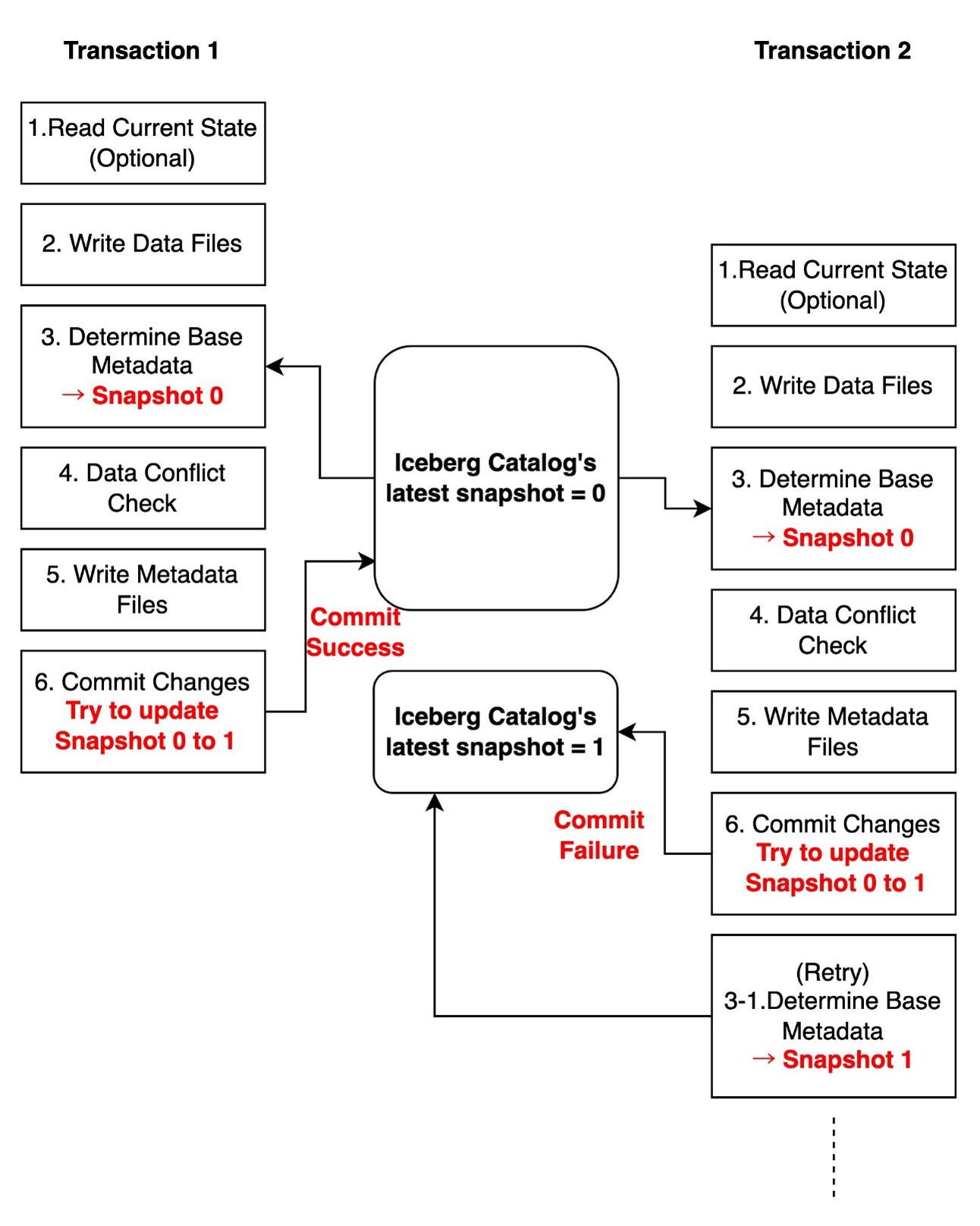
The following diagram illustrates this workflow.

Iceberg write transaction flow

Conflicts can occur at two critical points:

  • Data update conflicts – During validation when checking for data conflicts (Step 4)
  • Catalog commit conflicts – During the commit when attempting to update the catalog pointer (Step 6)

When working with Iceberg tables, understanding the types of conflicts that can occur and how they’re handled is crucial for building reliable data pipelines. Let’s examine the two primary types of conflicts and their characteristics.

Catalog commit conflicts

Catalog commit conflicts occur when multiple writers attempt to update the table metadata simultaneously. When a commit conflict occurs, Iceberg will automatically retry the operation based on the table’s write properties. The retry process only repeats the metadata commit, not the entire transaction, making it both safe and efficient. When the retries fail, the transaction fails with CommitFailedException.

In the following diagram, two transactions run concurrently. Transaction 1 successfully updates the table’s latest snapshot in the Iceberg catalog from 0 to 1. Meanwhile, transaction 2 attempts to update from Snapshot 0 to 1, but when it tries to commit the changes to the catalog, it finds that the latest snapshot has already been changed to 1 by transaction 1. As a result, transaction 2 needs to retry from Step 3.

Catalog commit conflicts1

These conflicts are typically transient and can be automatically resolved through retries. You can optionally configure write properties controlling commit retry behavior. For more detailed configuration, refer to Write properties in the Iceberg documentation.

The metadata used when reading the current state (Step 1) and the snapshot used as base metadata for updates (Step 3) can be different. Even if another transaction updates the latest snapshot between Steps 1 and 3, the current transaction can still commit changes to the catalog as long as it passes the data conflict check (Step 4). This means that even when computing changes and writing data files (Step 1 to 2) take a long time, and other transactions make changes during this period, the transaction can still attempt to commit to the catalog. This demonstrates Iceberg’s intelligent concurrency control mechanism.

The following diagram illustrates this workflow.

Catalog commit conflicts2

Data update conflicts

Data update conflicts are more complex and occur when concurrent transactions attempt to modify overlapping data. During a write transaction, the query engine checks consistency between the snapshot being written and the latest snapshot according to transaction isolation rules. When incompatibility is detected, the transaction fails with a ValidationException.

In the following diagram, two transactions run concurrently on an employee table containing id, name, and salary columns. Transaction 1 attempts to update a record based on Snapshot 0 and successfully commits this change, making the latest snapshot version 1. Meanwhile, transaction 2 also attempts to update the same record based on Snapshot 0. When transaction 2 initially scanned the data, the latest snapshot was 0, but it has since been updated to 1 by transaction 1. During the data conflict check, transaction 2 discovers that its changes conflict with Snapshot 1, resulting in the transaction failing.

data conflict

These conflicts can’t be automatically retried by Iceberg’s library because when data conflicts occur, the table’s state has changed, making it uncertain whether retrying the transaction would maintain overall data consistency. You need to handle this type of conflict based on your specific use case and requirements.

The following table summarizes how different write patterns have varying likelihood of conflicts.

Write Pattern Catalog Commit Conflict (Automatically retryable) Data Conflict (Non-retryable)
INSERT (AppendFiles) Yes Never
UPDATE/DELETE with Copy-on-Write or Merge-on-Read (OverwriteFiles) Yes Yes
Compaction (RewriteFiles) Yes Yes

Iceberg table’s isolation levels

Iceberg tables support two isolation levels: Serializable and Snapshot isolation. Both provide a read consistent view of the table and ensure readers see only committed data. Serializable isolation guarantees that concurrent operations run as if they were performed in some sequential order. Snapshot isolation provides weaker guarantees but offers better performance in environments with many concurrent writers. Under snapshot isolation, data conflict checks can pass even when concurrent transactions add new files with records that potentially match its conditions.

By default, Iceberg tables use serializable isolation. You can configure isolation levels for specific operations using table properties:

tbl_properties = {
    'write.delete.isolation-level' = 'serializable',
    'write.update.isolation-level' = 'serializable',
    'write.merge.isolation-level' = 'serializable'
}

You must choose the appropriate isolation level based on your use case. Note that for conflicts between streaming ingestion and compaction operations, which is one of the most common scenarios, snapshot isolation does not provide any additional benefits to the default serializable isolation. For more detailed configuration, see IsolationLevel.

Implementation patterns

Implementing robust concurrent write handling in Iceberg requires different strategies depending on the conflict type and use case. In this section, we share proven patterns for handling common scenarios.

Manage catalog commit conflicts

Catalog commit conflicts are relatively straightforward to handle through table properties. The following configurations serve as initial baseline settings that you can adjust based on your specific workload patterns and requirements.

For frequent concurrent writes (for example, streaming ingestion):

tbl_properties = {
    'commit.retry.num-retries': '10',
    'commit.retry.min-wait-ms': '100',
    'commit.retry.max-wait-ms': '10000',
    'commit.retry.total-timeout-ms': '1800000'
}

For maintenance operations (for example, compaction):

tbl_properties = {
    'commit.retry.num-retries': '4',
    'commit.retry.min-wait-ms': '1000',
    'commit.retry.max-wait-ms': '60000',
    'commit.retry.total-timeout-ms': '1800000'
}

Manage data update conflicts

For data update conflicts, which can’t be automatically retried, you need to implement a custom retry mechanism with proper error handling. A common scenario is when stream UPSERT ingestion conflicts with concurrent compaction operations. In such cases, the stream ingestion job should typically implement retries to handle incoming data. Without proper error handling, the job will fail with a ValidationException.

We show two example scripts demonstrating a practical implementation of error handling for data conflicts in Iceberg streaming jobs. The code specifically catches ValidationException through Py4JJavaError handling, which is essential for proper Java-Python interaction. It includes exponential backoff and jitter strategy by adding a random delay of 0–25% to each retry interval. For example, if the base exponential backoff time is 4 seconds, the actual retry delay will be between 4–5 seconds, helping prevent immediate retry storms while maintaining reasonable latency.

In this example, we create a scenario with frequent MERGE operations on the same records by using 'value' as a unique identifier and artificially limiting its range. By applying a modulo operation (value % 20), we constrain all values to fall within 0–19, which means multiple updates will target the same records. For instance, if the original stream contains values 0, 20, 40, and 60, they will all be mapped to 0, resulting in multiple MERGE operations targeting the same record. We then use groupBy and max aggregation to simulate a typical UPSERT pattern where we keep the latest record for each value. The transformed data is stored in a temporary view that serves as the source table in the MERGE statement, allowing us to perform UPDATE operations using 'value' as the matching condition. This setup helps demonstrate how our retry mechanism handles ValidationExceptions that occur when concurrent transactions attempt to modify the same records.

The first example uses Spark Structured Streaming using a rate source with a 20-second trigger interval to demonstrate the retry mechanism’s behavior when concurrent operations cause data conflicts. Replace <database_name> with your database name, <table_name> with your table name, amzn-s3-demo-bucket with your S3 bucket name.

import time
import random
from pyspark.sql import SparkSession
from py4j.protocol import Py4JJavaError
from pyspark.sql.functions import max as max_

CATALOG = "glue_catalog"
DATABASE = "<database_name>"
TABLE = "<table_name>"
BUCKET = "amzn-s3-demo-bucket"

spark = SparkSession.builder \
    .appName("IcebergUpsertExample") \
    .config(f"spark.sql.catalog.{CATALOG}", "org.apache.iceberg.spark.SparkCatalog") \
    .config("spark.sql.extensions","org.apache.iceberg.spark.extensions.IcebergSparkSessionExtensions") \
    .config(f"spark.sql.catalog.{CATALOG}.io-impl","org.apache.iceberg.aws.s3.S3FileIO") \
    .config("spark.sql.defaultCatalog", CATALOG) \
    .config(f"spark.sql.catalog.{CATALOG}.type", "glue") \
    .getOrCreate()
    
spark.sql(f"""
    CREATE TABLE IF NOT EXISTS {DATABASE}.{TABLE} (
        timestamp TIMESTAMP,
        value LONG
    )
    USING iceberg
    LOCATION 's3://{BUCKET}/warehouse'
""")

def backoff(attempt):
    """Exponential backoff with jitter"""
    exp_backoff = min(2 ** attempt, 60)
    jitter = random.uniform(0, 0.25 * exp_backoff)
    return exp_backoff + jitter

def is_validation_exception(java_exception):
    """Check if exception is ValidationException"""
    cause = java_exception
    while cause is not None:
        if "org.apache.iceberg.exceptions.ValidationException" in str(cause.getClass().getName()):
            return True
        cause = cause.getCause()
    return False

def upsert_with_retry(microBatchDF, batchId):
    max_retries = 5
    attempt = 0
    
    # Use a narrower key range to intentionally increase updates for the same value in MERGE
    transformedDF = microBatchDF \
        .selectExpr("timestamp", "value % 20 AS value") \
        .groupBy("value") \
        .agg(max_("timestamp").alias("timestamp"))
        
    view_name = f"incoming_data_{batchId}"
    transformedDF.createOrReplaceGlobalTempView(view_name)
    
    while attempt < max_retries:
        try:
            spark.sql(f"""
                MERGE INTO {DATABASE}.{TABLE} AS t
                USING global_temp.{view_name} AS i
                ON t.value = i.value
                WHEN MATCHED THEN
                  UPDATE SET
                    t.timestamp = i.timestamp,
                    t.value     = i.value
                WHEN NOT MATCHED THEN
                  INSERT (timestamp, value)
                  VALUES (i.timestamp, i.value)
            """)
            
            print(f"[SUCCESS] Batch {batchId} processed successfully")
            return
            
        except Py4JJavaError as e:
            if is_validation_exception(e.java_exception):
                attempt += 1
                if attempt < max_retries:
                    delay = backoff(attempt)
                    print(f"[RETRY] Batch {batchId} failed with ValidationException. "
                          f"Retrying in {delay} seconds. Attempt {attempt}/{max_retries}")
                    time.sleep(delay)
                else:
                    print(f"[FAILED] Batch {batchId} failed after {max_retries} attempts")
                    raise

# Sample streaming query setup
df = spark.readStream \
    .format("rate") \
    .option("rowsPerSecond", 10) \
    .load()

# Start streaming query
query = df.writeStream \
    .trigger(processingTime="20 seconds") \
    .option("checkpointLocation", f"s3://{BUCKET}/checkpointLocation") \
    .foreachBatch(upsert_with_retry) \
    .start()

query.awaitTermination()

The second example uses GlueContext.forEachBatch available on AWS Glue Streaming jobs. The implementation pattern for the retry mechanism remains the same, but the main differences are the initial setup using GlueContext and how to create a streaming DataFrame. Although our example uses spark.readStream with a rate source for demonstration, in actual AWS Glue Streaming jobs, you would typically create your streaming DataFrame using glueContext.create_data_frame.from_catalog to read from sources like Amazon Kinesis or Kafka. For more details, see AWS Glue Streaming connections. Replace <database_name> with your database name, <table_name> with your table name, amzn-s3-demo-bucket with your S3 bucket name.

import time
import random
from py4j.protocol import Py4JJavaError
from pyspark.context import SparkContext
from awsglue.context import GlueContext
from pyspark.sql import SparkSession
from pyspark.sql.functions import max as max_

CATALOG = "glue_catalog"
DATABASE = "<database_name>"
TABLE = "<table_name>"
BUCKET = "amzn-s3-demo-bucket"

spark = SparkSession.builder \
    .appName("IcebergUpsertExample") \
    .config(f"spark.sql.catalog.{CATALOG}", "org.apache.iceberg.spark.SparkCatalog") \
    .config("spark.sql.extensions","org.apache.iceberg.spark.extensions.IcebergSparkSessionExtensions") \
    .config(f"spark.sql.catalog.{CATALOG}.io-impl","org.apache.iceberg.aws.s3.S3FileIO") \
    .config("spark.sql.defaultCatalog", CATALOG) \
    .config(f"spark.sql.catalog.{CATALOG}.type", "glue") \
    .getOrCreate()

sc = spark.sparkContext
glueContext = GlueContext(sc)

spark.sql(f"""
    CREATE TABLE IF NOT EXISTS {DATABASE}.{TABLE} (
        timestamp TIMESTAMP,
        value LONG
    )
    USING iceberg
    LOCATION 's3://{BUCKET}/warehouse'
""")

def backoff(attempt):
    exp_backoff = min(2 ** attempt, 60)
    jitter = random.uniform(0, 0.25 * exp_backoff)
    return exp_backoff + jitter

def is_validation_exception(java_exception):
    cause = java_exception
    while cause is not None:
        if "org.apache.iceberg.exceptions.ValidationException" in str(cause.getClass().getName()):
            return True
        cause = cause.getCause()
    return False

def upsert_with_retry(batch_df, batchId):
    max_retries = 5
    attempt = 0
    transformedDF = batch_df.selectExpr("timestamp", "value % 20 AS value") \
                           .groupBy("value") \
                           .agg(max_("timestamp").alias("timestamp"))
                           
    view_name = f"incoming_data_{batchId}"
    transformedDF.createOrReplaceGlobalTempView(view_name)
    
    while attempt < max_retries:
        try:
            spark.sql(f"""
                MERGE INTO {DATABASE}.{TABLE} AS t
                USING global_temp.{view_name} AS i
                ON t.value = i.value
                WHEN MATCHED THEN
                  UPDATE SET
                    t.timestamp = i.timestamp,
                    t.value     = i.value
                WHEN NOT MATCHED THEN
                  INSERT (timestamp, value)
                  VALUES (i.timestamp, i.value)
            """)
            print(f"[SUCCESS] Batch {batchId} processed successfully")
            return
        except Py4JJavaError as e:
            if is_validation_exception(e.java_exception):
                attempt += 1
                if attempt < max_retries:
                    delay = backoff(attempt)
                    print(f"[RETRY] Batch {batchId} failed with ValidationException. "
                          f"Retrying in {delay} seconds. Attempt {attempt}/{max_retries}")
                    time.sleep(delay)
                else:
                    print(f"[FAILED] Batch {batchId} failed after {max_retries} attempts")
                    raise

# Sample streaming query setup
streaming_df = spark.readStream \
    .format("rate") \
    .option("rowsPerSecond", 10) \
    .load()

# In actual Glue Streaming jobs, you would typically create a streaming DataFrame like this:
"""
streaming_df = glueContext.create_data_frame.from_catalog(
    database = "database",
    table_name = "table_name",
    transformation_ctx = "streaming_df",
    additional_options = {
        "startingPosition": "TRIM_HORIZON",
        "inferSchema": "false"
    }
)
"""

glueContext.forEachBatch(
    frame=streaming_df,
    batch_function=upsert_with_retry,
    options={
        "windowSize": "20 seconds",
        "checkpointLocation": f"s3://{BUCKET}/checkpointLocation"
    }
)

Minimize conflict possibility by scoping your operations

When performing maintenance operations like compaction or updates, it’s recommended to narrow down the scope to minimize overlap with other operations. For example, consider a table partitioned by date where a streaming job continuously upserts data for the latest date. The following is the example script to run the rewrite_data_files procedure to compact the entire table:

# Example of broad scope compaction
spark.sql("""
   CALL catalog_name.system.rewrite_data_files(
       table => 'db.table_name'
   )
""")

By narrowing the compaction scope with a date partition filter in the where clause, you can avoid conflicts between streaming ingestion and compaction operations. The streaming job can continue to work with the latest partition while compaction processes historical data.

# Narrow down the scope by partition
spark.sql("""
    CALL catalog_name.system.rewrite_data_files(
        table => 'db.table_name',
        where => 'date_partition < current_date'
    )
""")

Conclusion

Successfully managing concurrent writes in Iceberg requires understanding both the table architecture and various conflict scenarios. In this post, we explored how to implement reliable conflict handling mechanisms in production environments.

The most critical concept to remember is the distinction between catalog commit conflicts and data conflicts. Although catalog commit conflicts can be handled through automatic retries and table properties configuration, data conflicts require careful implementation of custom handling logic. This becomes particularly important when implementing maintenance operations like compaction, where using the where clause in rewrite_data_files can significantly minimize conflict potential by reducing the scope of operations.

For streaming pipelines, the key to success lies in implementing proper error handling that can differentiate between conflict types and respond appropriately. This includes configuring suitable retry settings through table properties and implementing backoff strategies that align with your workload characteristics. When combined with well-timed maintenance operations, these patterns help build resilient data pipelines that can handle concurrent writes reliably.

By applying these patterns and understanding the underlying mechanisms of Iceberg’s concurrency model, you can build robust data pipelines that effectively handle concurrent write scenarios while maintaining data consistency and reliability.


About the Authors

Sotaro Hikita is an Analytics Solutions Architect. He supports customers across a wide range of industries in building and operating analytics platforms more effectively. He is particularly passionate about big data technologies and open source software.

Noritaka Sekiyama is a Principal Big Data Architect on the AWS Glue team. He works based in Tokyo, Japan. He is responsible for building software artifacts to help customers. In his spare time, he enjoys cycling with his road bike.

Develop and test AWS Glue 5.0 jobs locally using a Docker container

Post Syndicated from Subramanya Vajiraya original https://aws.amazon.com/blogs/big-data/develop-and-test-aws-glue-5-0-jobs-locally-using-a-docker-container/

AWS Glue is a serverless data integration service that allows you to process and integrate data coming through different data sources at scale. AWS Glue 5.0, the latest version of AWS Glue for Apache Spark jobs, provides a performance-optimized Apache Spark 3.5 runtime experience for batch and stream processing. With AWS Glue 5.0, you get improved performance, enhanced security, support for the next generation of Amazon SageMaker, and more. AWS Glue 5.0 enables you to develop, run, and scale your data integration workloads and get insights faster.

AWS Glue accommodates various development preferences through multiple job creation approaches. For developers who prefer direct coding, Python or Scala development is available using the AWS Glue ETL library.

Building production-ready data platforms requires robust development processes and continuous integration and delivery (CI/CD) pipelines. To support diverse development needs—whether on local machines, Docker containers on Amazon Elastic Compute Cloud (Amazon EC2), or other environments—AWS provides an official AWS Glue Docker image through the Amazon ECR Public Gallery. The image enables developers to work efficiently in their preferred environment while using the AWS Glue ETL library.

In this post, we show how to develop and test AWS Glue 5.0 jobs locally using a Docker container. This post is an updated version of the post Develop and test AWS Glue version 3.0 and 4.0 jobs locally using a Docker container, and uses AWS Glue 5.0 .

Available Docker images

The following Docker images are available for the Amazon ECR Public Gallery:

  • AWS Glue version 5.0 – ecr.aws/glue/aws-glue-libs:5

AWS Glue Docker images are compatible with both x86_64 and arm64.

In this post, we use public.ecr.aws/glue/aws-glue-libs:5 and run the container on a local machine (Mac, Windows, or Linux). This container image has been tested for AWS Glue 5.0 Spark jobs. The image contains the following:

To set up your container, you pull the image from the ECR Public Gallery and then run the container. We demonstrate how to run your container with the following methods, depending on your requirements:

  • spark-submit
  • REPL shell (pyspark)
  • pytest
  • Visual Studio Code

Prerequisites

Before you start, make sure that Docker is installed and the Docker daemon is running. For installation instructions, see the Docker documentation for Mac, Windows, or Linux. Also make sure that you have at least 7 GB of disk space for the image on the host running Docker.

Configure AWS credentials

To enable AWS API calls from the container, set up your AWS credentials with the following steps:

  1. Create an AWS named profile.
  2. Open cmd on Windows or a terminal on Mac/Linux, and run the following command:
PROFILE_NAME="profile_name"

In the following sections, we use this AWS named profile.

Pull the image from the ECR Public Gallery

If you’re running Docker on Windows, choose the Docker icon (right-click) and choose Switch to Linux containers before pulling the image.

Run the following command to pull the image from the ECR Public Gallery:

docker pull public.ecr.aws/glue/aws-glue-libs:5

Run the container

Now you can run a container using this image. You can choose any of following methods based on your requirements.

spark-submit

You can run an AWS Glue job script by running the spark-submit command on the container.

Write your job script (sample.py in the following example) and save it under the /local_path_to_workspace/src/ directory using the following commands:

$ WORKSPACE_LOCATION=/local_path_to_workspace
$ SCRIPT_FILE_NAME=sample.py
$ mkdir -p ${WORKSPACE_LOCATION}/src
$ vim ${WORKSPACE_LOCATION}/src/${SCRIPT_FILE_NAME}

These variables are used in the following docker run command. The sample code (sample.py) used in the spark-submit command is included in the appendix at the end of this post.

Run the following command to run the spark-submit command on the container to submit a new Spark application:

$ docker run -it --rm \
    -v ~/.aws:/home/hadoop/.aws \
    -v $WORKSPACE_LOCATION:/home/hadoop/workspace/ \
    -e AWS_PROFILE=$PROFILE_NAME \
    --name glue5_spark_submit \
    public.ecr.aws/glue/aws-glue-libs:5 \
    spark-submit /home/hadoop/workspace/src/$SCRIPT_FILE_NAME

REPL shell (pyspark)

You can run a REPL (read-eval-print loop) shell for interactive development. Run the following command to run the pyspark command on the container to start the REPL shell:

$ docker run -it --rm \
    -v ~/.aws:/home/hadoop/.aws \
    -e AWS_PROFILE=$PROFILE_NAME \
    --name glue5_pyspark \
    public.ecr.aws/glue/aws-glue-libs:5 \
    pyspark

You will see following output:

Python 3.11.6 (main, Jan  9 2025, 00:00:00) [GCC 11.4.1 20230605 (Red Hat 11.4.1-2)] on linux
Type "help", "copyright", "credits" or "license" for more information.
Setting default log level to "WARN".
To adjust logging level use sc.setLogLevel(newLevel). For SparkR, use setLogLevel(newLevel).
Welcome to
      ____              __
     / __/__  ___ _____/ /__
    _\ \/ _ \/ _ `/ __/  '_/
   /__ / .__/\_,_/_/ /_/\_\   version 3.5.2-amzn-1
      /_/

Using Python version 3.11.6 (main, Jan  9 2025 00:00:00)
Spark context Web UI available at None
Spark context available as 'sc' (master = local[*], app id = local-1740643079929).
SparkSession available as 'spark'.
>>> 

With this REPL shell, you can code and test interactively.

pytest

For unit testing, you can use pytest for AWS Glue Spark job scripts.

Run the following commands for preparation:

$ WORKSPACE_LOCATION=/local_path_to_workspace
$ SCRIPT_FILE_NAME=sample.py
$ UNIT_TEST_FILE_NAME=test_sample.py
$ mkdir -p ${WORKSPACE_LOCATION}/tests
$ vim ${WORKSPACE_LOCATION}/tests/${UNIT_TEST_FILE_NAME}

Now let’s invoke pytest using docker run:

$ docker run -i --rm \
    -v ~/.aws:/home/hadoop/.aws \
    -v $WORKSPACE_LOCATION:/home/hadoop/workspace/ \
    --workdir /home/hadoop/workspace \
    -e AWS_PROFILE=$PROFILE_NAME \
    --name glue5_pytest \
    public.ecr.aws/glue/aws-glue-libs:5 \
    -c "python3 -m pytest --disable-warnings"

When pytest finishes executing unit tests, your output will look something like the following:

============================= test session starts ==============================
platform linux -- Python 3.11.6, pytest-8.3.4, pluggy-1.5.0
rootdir: /home/hadoop/workspace
plugins: integration-mark-0.2.0
collected 1 item

tests/test_sample.py .                                                   [100%]

======================== 1 passed, 1 warning in 34.28s =========================

Visual Studio Code

To set up the container with Visual Studio Code, complete the following steps:

  1. Install Visual Studio Code.
  2. Install Python.
  3. Install Dev Containers.
  4. Open the workspace folder in Visual Studio Code.
  5. Press Ctrl+Shift+P (Windows/Linux) or Cmd+Shift+P (Mac).
  6. Enter Preferences: Open Workspace Settings (JSON).
  7. Press Enter.
  8. Enter following JSON and save it:
{
    "python.defaultInterpreterPath": "/usr/bin/python3.11",
    "python.analysis.extraPaths": [
        "/usr/lib/spark/python/lib/py4j-0.10.9.7-src.zip:/usr/lib/spark/python/:/usr/lib/spark/python/lib/",
    ]
}

Now you’re ready to set up the container.

  1. Run the Docker container:
$ docker run -it --rm \
    -v ~/.aws:/home/hadoop/.aws \
    -v $WORKSPACE_LOCATION:/home/hadoop/workspace/ \
    -e AWS_PROFILE=$PROFILE_NAME \
    --name glue5_pyspark \
    public.ecr.aws/glue/aws-glue-libs:5 \
    pyspark
  1. Start Visual Studio Code.
  2. Choose Remote Explorer in the navigation pane.
  3. Choose the container ecr.aws/glue/aws-glue-libs:5 (right-click) and choose Attach in Current Window.

  1. If the following dialog appears, choose Got it.

  1. Open /home/hadoop/workspace/.

  1. Create an AWS Glue PySpark script and choose Run.

You should see the successful run on the AWS Glue PySpark script.

Changes between the AWS Glue 4.0 and AWS Glue 5.0 Docker image

The following are major changes between the AWS Glue 4.0 and Glue 5.0 Docker image:

  • In AWS Glue 5.0, there is a single container image for both batch and streaming jobs. This differs from AWS Glue 4.0, where there was one image for batch and another for streaming.
  • In AWS Glue 5.0, the default user name of the container is hadoop. In AWS Glue 4.0, the default user name was glue_user.
  • In AWS Glue 5.0, several additional libraries, including JupyterLab and Livy, have been removed from the image. You can manually install them.
  • In AWS Glue 5.0, all of Iceberg, Hudi, and Delta libraries are pre-loaded by default, and the environment variable DATALAKE_FORMATS is no longer needed. Until AWS Glue 4.0, the environment variable DATALAKE_FORMATS was used to specify whether the specific table format is loaded.

The preceding list is specific to the Docker image. To learn more about AWS Glue 5.0 updates, see Introducing AWS Glue 5.0 for Apache Spark and Migrating AWS Glue for Spark jobs to AWS Glue version 5.0.

Considerations

Keep in mind that the following features are not supported when using the AWS Glue container image to develop job scripts locally:

Conclusion

In this post, we explored how the AWS Glue 5.0 Docker images provide a flexible foundation for developing and testing AWS Glue job scripts in your preferred environment. These images, readily available in the Amazon ECR Public Gallery, streamline the development process by offering a consistent, portable environment for AWS Glue development.

To learn more about how to build end-to-end development pipeline, see End-to-end development lifecycle for data engineers to build a data integration pipeline using AWS Glue. We encourage you to explore these capabilities and share your experiences with the AWS community.


Appendix A: AWS Glue job sample codes for testing

This appendix introduces three different scripts as AWS Glue job sample codes for testing purposes. You can use any of them in the tutorial.

The following sample.py code uses the AWS Glue ETL library with an Amazon Simple Storage Service (Amazon S3) API call. The code requires Amazon S3 permissions in AWS Identity and Access Management (IAM). You need to grant the IAM-managed policy arn:aws:iam::aws:policy/AmazonS3ReadOnlyAccess or IAM custom policy that allows you to make ListBucket and GetObject API calls for the S3 path.

import sys
from pyspark.context import SparkContext
from awsglue.context import GlueContext
from awsglue.job import Job
from awsglue.utils import getResolvedOptions


class GluePythonSampleTest:
    def __init__(self):
        params = []
        if '--JOB_NAME' in sys.argv:
            params.append('JOB_NAME')
        args = getResolvedOptions(sys.argv, params)

        self.context = GlueContext(SparkContext.getOrCreate())
        self.job = Job(self.context)

        if 'JOB_NAME' in args:
            jobname = args['JOB_NAME']
        else:
            jobname = "test"
        self.job.init(jobname, args)

    def run(self):
        dyf = read_json(self.context, "s3://awsglue-datasets/examples/us-legislators/all/persons.json")
        dyf.printSchema()

        self.job.commit()


def read_json(glue_context, path):
    dynamicframe = glue_context.create_dynamic_frame.from_options(
        connection_type='s3',
        connection_options={
            'paths': [path],
            'recurse': True
        },
        format='json'
    )
    return dynamicframe


if __name__ == '__main__':
    GluePythonSampleTest().run()

The following test_sample.py code is a sample for a unit test of sample.py:

The following test_sample.py code is a sample for a unit test of sample.py:
import pytest
from pyspark.context import SparkContext
from awsglue.context import GlueContext
from awsglue.job import Job
from awsglue.utils import getResolvedOptions
import sys
from src import sample


@pytest.fixture(scope="module", autouse=True)
def glue_context():
    sys.argv.append('--JOB_NAME')
    sys.argv.append('test_count')

    args = getResolvedOptions(sys.argv, ['JOB_NAME'])
    context = GlueContext(SparkContext.getOrCreate())
    job = Job(context)
    job.init(args['JOB_NAME'], args)

Appendix B: Adding JDBC drivers and Java libraries

To add a JDBC driver not currently available in the container, you can create a new directory under your workspace with the JAR files you need and mount the directory to /opt/spark/jars/ in the docker run command. JAR files found under /opt/spark/jars/ within the container are automatically added to Spark Classpath and will be available for use during the job run.

For example, you can use the following docker run command to add JDBC driver jars to a PySpark REPL shell:

$ docker run -it --rm \
    -v ~/.aws:/home/hadoop/.aws \
    -v $WORKSPACE_LOCATION:/home/hadoop/workspace/ \
    -v $WORKSPACE_LOCATION/jars/:/opt/spark/jars/ \
    --workdir /home/hadoop/workspace \
    -e AWS_PROFILE=$PROFILE_NAME \
    --name glue5_jdbc \
    public.ecr.aws/glue/aws-glue-libs:5 \
    pyspark

As highlighted earlier, the customJdbcDriverS3Path connection option can’t be used to import a custom JDBC driver from Amazon S3 in AWS Glue container images.

Appendix C: Adding Livy and JupyterLab

The AWS Glue 5.0 container image doesn’t have Livy installed by default. You can create a new container image extending the AWS Glue 5.0 container image as the base. The following Dockerfile demonstrates how you can extend the Docker image to include additional components you need to enhance your development and testing experience.

To get started, create a directory on your workstation and place the Dockerfile.livy_jupyter file in the directory:

$ mkdir -p $WORKSPACE_LOCATION/jupyterlab/
$ cd $WORKSPACE_LOCATION/jupyterlab/
$ vim Dockerfile.livy_jupyter

The following code is Dockerfile.livy_jupyter:

FROM public.ecr.aws/glue/aws-glue-libs:5 AS glue-base

ENV LIVY_SERVER_JAVA_OPTS="--add-opens java.base/java.lang.invoke=ALL-UNNAMED --add-opens=java.base/java.nio=ALL-UNNAMED --add-opens=java.base/sun.nio.ch=ALL-UNNAMED --add-opens=java.base/sun.nio.cs=ALL-UNNAMED --add-opens=java.base/java.util.concurrent.atomic=ALL-UNNAMED"

# Download Livy
ADD --chown=hadoop:hadoop https://dlcdn.apache.org/incubator/livy/0.8.0-incubating/apache-livy-0.8.0-incubating_2.12-bin.zip ./

# Install and configure Livy
RUN unzip apache-livy-0.8.0-incubating_2.12-bin.zip && \
rm apache-livy-0.8.0-incubating_2.12-bin.zip && \
mv apache-livy-0.8.0-incubating_2.12-bin livy && \
mkdir -p livy/logs && \
cat <<EOF >> livy/conf/livy.conf
livy.server.host = 0.0.0.0
livy.server.port = 8998
livy.spark.master = local
livy.repl.enable-hive-context = true
livy.spark.scala-version = 2.12
EOF && \
cat <<EOF >> livy/conf/log4j.properties
log4j.rootCategory=INFO,console
log4j.appender.console=org.apache.log4j.ConsoleAppender
log4j.appender.console.target=System.err
log4j.appender.console.layout=org.apache.log4j.PatternLayout
log4j.appender.console.layout.ConversionPattern=%d{yy/MM/dd HH:mm:ss} %p %c{1}: %m%n
log4j.logger.org.eclipse.jetty=WARN
EOF

# Switching to root user temporarily to install dev dependency packages
USER root 
RUN dnf update -y && dnf install -y krb5-devel gcc python3.11-devel
USER hadoop

# Install SparkMagic and JupyterLab
RUN export PATH=$HOME/.local/bin:$HOME/livy/bin/:$PATH && \
printf "numpy<2\nIPython<=7.14.0\n" > /tmp/constraint.txt && \
pip3.11 --no-cache-dir install --constraint /tmp/constraint.txt --user pytest boto==2.49.0 jupyterlab==3.6.8 IPython==7.14.0 ipykernel==5.5.6 ipywidgets==7.7.2 sparkmagic==0.21.0 jupyterlab_widgets==1.1.11 && \
jupyter-kernelspec install --user $(pip3.11 --no-cache-dir show sparkmagic | grep Location | cut -d" " -f2)/sparkmagic/kernels/sparkkernel && \
jupyter-kernelspec install --user $(pip3.11 --no-cache-dir show sparkmagic | grep Location | cut -d" " -f2)/sparkmagic/kernels/pysparkkernel && \
jupyter server extension enable --user --py sparkmagic && \
cat <<EOF >> /home/hadoop/.local/bin/entrypoint.sh
#!/usr/bin/env bash
mkdir -p /home/hadoop/workspace/
livy-server start
sleep 5
jupyter lab --no-browser --ip=0.0.0.0 --allow-root --ServerApp.root_dir=/home/hadoop/workspace/ --ServerApp.token='' --ServerApp.password=''
EOF

# Setup Entrypoint script
RUN chmod +x /home/hadoop/.local/bin/entrypoint.sh

# Add default SparkMagic Config
ADD --chown=hadoop:hadoop https://raw.githubusercontent.com/jupyter-incubator/sparkmagic/refs/heads/master/sparkmagic/example_config.json .sparkmagic/config.json

# Update PATH var
ENV PATH=/home/hadoop/.local/bin:/home/hadoop/livy/bin/:$PATH

ENTRYPOINT ["/home/hadoop/.local/bin/entrypoint.sh"]

Run the docker build command to build the image:

docker build \
    -t glue_v5_livy \
    --file $WORKSPACE_LOCATION/jupyterlab/Dockerfile.livy_jupyter \
    $WORKSPACE_LOCATION/jupyterlab/

When the image build is complete, you can use the following docker run command to start the newly built image:

docker run -it --rm \
    -v ~/.aws:/home/hadoop/.aws \
    -v $WORKSPACE_LOCATION:/home/hadoop/workspace/ \
    -p 8998:8998 \
    -p 8888:8888 \
    -e AWS_PROFILE=$PROFILE_NAME \
    --name glue5_jupyter  \
    glue_v5_livy

Appendix D: Adding extra Python libraries

In this section, we discuss adding extra Python libraries and installing Python packages using

Local Python libraries

To add local Python libraries, place them under a directory and assign the path to $EXTRA_PYTHON_PACKAGE_LOCATION:

$ docker run -it --rm \
    -v ~/.aws:/home/hadoop/.aws \
    -v $WORKSPACE_LOCATION:/home/hadoop/workspace/ \
    -v $EXTRA_PYTHON_PACKAGE_LOCATION:/home/hadoop/workspace/extra_python_path/ \
    --workdir /home/hadoop/workspace \
    -e AWS_PROFILE=$PROFILE_NAME \
    --name glue5_pylib \
    public.ecr.aws/glue/aws-glue-libs:5 \
    -c 'export PYTHONPATH=/home/hadoop/workspace/extra_python_path/:$PYTHONPATH; pyspark'

To validate that the path has been added to PYTHONPATH, you can check for its existence in sys.path:

Python 3.11.6 (main, Jan  9 2025, 00:00:00) [GCC 11.4.1 20230605 (Red Hat 11.4.1-2)] on linux
Type "help", "copyright", "credits" or "license" for more information.
Setting default log level to "WARN".
To adjust logging level use sc.setLogLevel(newLevel). For SparkR, use setLogLevel(newLevel).
Welcome to
      ____              __
     / __/__  ___ _____/ /__
    _\ \/ _ \/ _ `/ __/  '_/
   /__ / .__/\_,_/_/ /_/\_\   version 3.5.2-amzn-1
      /_/

Using Python version 3.11.6 (main, Jan  9 2025 00:00:00)
Spark context Web UI available at None
Spark context available as 'sc' (master = local[*], app id = local-1740719582296).
SparkSession available as 'spark'.
>>> import sys
>>> "/home/hadoop/workspace/extra_python_path" in sys.path
True

Installing Python packages using pip

To install packages from PyPI (or any other artifact repository) using pip, you can use the following approach:

docker run -it --rm \
    -v ~/.aws:/home/hadoop/.aws \
    -v $WORKSPACE_LOCATION:/home/hadoop/workspace/ \
    --workdir /home/hadoop/workspace \
    -e AWS_PROFILE=$PROFILE_NAME \
    -e SCRIPT_FILE_NAME=$SCRIPT_FILE_NAME \
    --name glue5_pylib \
    public.ecr.aws/glue/aws-glue-libs:5 \
    -c 'pip3 install snowflake==1.0.5; spark-submit /home/hadoop/workspace/src/$SCRIPT_FILE_NAME'

About the Authors

Author Headshot - Subramanya VajirayaSubramanya Vajiraya is a Sr. Cloud Engineer (ETL) at AWS Sydney specialized in AWS Glue. He is passionate about helping customers solve issues related to their ETL workload and implementing scalable data processing and analytics pipelines on AWS. Outside of work, he enjoys going on bike rides and taking long walks with his dog Ollie.

Noritaka Sekiyama is a Principal Big Data Architect on the AWS Glue team. He works based in Tokyo, Japan. He is responsible for building software artifacts to help customers. In his spare time, he enjoys cycling with his road bike.

Enhancing Adobe Marketo Engage Data Analysis with AWS Glue Integration

Post Syndicated from Kenny Rajan original https://aws.amazon.com/blogs/big-data/enhancing-adobe-marketo-engage-data-analysis-with-aws-glue-integration/

Today’s digital-first, B2B landscape presents marketers with complex challenges as they navigate sophisticated buyer journeys involving diverse decision-making groups. Adobe Marketo Engage offers a comprehensive marketing hub for orchestrating cross-channel campaigns. Using AI-driven personalization, automation, and real-time analytics, it helps businesses acquire and retain customers throughout their buying journeys. Marketo Engage empowers B2B marketers to navigate modern complexities and successfully drive measurable business growth through multi-channel engagement, automated customer journeys, and sales-marketing collaboration.

To further enhance their B2B marketing capabilities, organizations are now looking to fully use their marketing data for more informed decision-making and strategy optimization. Recognizing the need to simplify the analytics pipeline, AWS introduced software as a service (SaaS) connectivity for Marketo Engage through AWS Glue, delivering insights faster to enable data-driven decisions. The agile, serverless nature of AWS Glue meets a range of data analytics needs while reducing costs. This powerful integration links the robust marketing automation features of Marketo Engage with AWS’s advanced analytics ecosystem. By seamlessly connecting the platforms, businesses can extract greater value from marketing data, gaining deeper insights into customer behavior and campaign performance. Together, AWS Glue and Marketo Engage unlock new possibilities for data-driven marketing:

  • Marketing-sales alignment – Helps automate the transfer of lead and opportunity data between Marketo Engage and CRM systems, making sure that sales and marketing teams are aligned and responsive to customer needs
  • Enhanced analytics – Connects Marketo Engage with business intelligence (BI) tools for data-driven campaign optimization, allowing marketers to extract meaningful insights and make informed decisions
  • Data integrity – Maintains consistent, high-quality data across all systems, providing reliability and accuracy in marketing and sales operations
  • Improved lead quality – Refines lead scoring processes by using the advanced analytics capabilities of AWS, resulting in better-qualified leads and improved sales conversions
  • Unified customer view – Provides comprehensive customer insights using enriched AWS datasets for Marketo Engage, offering a holistic understanding of customer interactions and behaviors

In this post, we show you how to use AWS Glue to extract data from Marketo Engage for data processing and enrichment on AWS for use in marketing analytics workflows.

Solution Overview

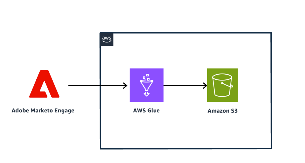
We explore a use case in which a company wants to run analysis for campaign leads in multiple countries. The resulting leads will be shared with the respective regional marketing representatives. The solution uses AWS Glue to extract data from Marketo Engage and save it in an Amazon Simple Storage Service (Amazon S3) bucket. The following diagram illustrates the solution architecture.

1_Scope-of-the-solutions_AWSGLue_Marketo_Engage_Flow

In the following sections, we walk through the high-level steps to implement the solution:

  1. Create AWS resources to connect to Marketo Engine and store data.
  2. Create an AWS Glue connection.
  3. Create an extract, transform, and load (ETL) job using AWS Glue Studio.
  4. Analyze the data.

Prerequisites

To set up the integration between Marketo Engage and AWS, the following components are required:

  • A Marketo Engage account – If you don’t already have one, create a Marketo Engage application and record the Munchkin ID, client ID, and client secret for the application. Refer to the Marketo Engage developer portal to set up the connection.
  • An AWS Glue database – This will serve as the data interaction interface on AWS. The database will expose the data residing in Amazon S3 as queryable AWS Glue tables. For this post, our database is called marketodb.

Create AWS resources to connect to Marketo Engage and store data

We use an AWS CloudFormation template to create an S3 bucket to store data, an AWS Secrets Manager secret for Marketo Engage that the AWS Glue connection needs, and an AWS Identity and Access Management (IAM) role to access the secret. Complete the following steps:

  1. Click Launch Stack below.
    Click here to launch the Cloud Fromation stack
  2. On the Specify stack details page, enter a name for the stack.
  3. Specify the Marketo client secret.
  4. Choose Next.
  5. On the Configure stack options page, choose Next.
  6. On the Review page, select I acknowledge that AWS CloudFormation might create IAM resources.
  7. Choose Submit. Note: The stack takes about 2 minutes to deploy.
  8. After the stack is created, make a note of the S3AccessRoleARN You will need this to create the Marketo Engage connection.

Create an AWS Glue connection

Complete the following steps to create an AWS Glue connection:

  1. On the AWS Glue console, choose Data connections in the navigation pane.
  2. Choose Create connection.
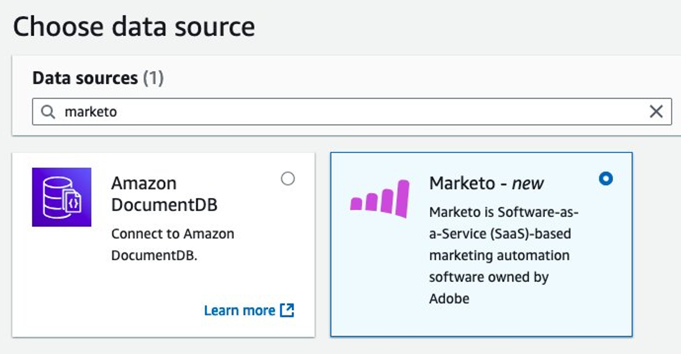
  3. For Data sources, select Marketo.

2-Glue-Data-Source-page

  1. Enter the Adobe MUNCHKIN_ID.
  2. Choose the IAM role created in the previous section as the AWS Glue connection IAM service role.
  3. Provide the Adobe ClientId as the user-managed client application client ID.
  4. Provide the Secrets Manager secret you created earlier.
  5. Choose Next.
  6. Specify your preferred connection name.
  7. Choose Next.
  8. Review the settings, then choose Create connection.

Entering-Marketo-Connectiondetails-in-glue.jpg

Create an ETL job using AWS Glue Studio

Complete the following steps to create an ETL job:

  1. On the AWS Glue console, choose ETL jobs in the navigation pane.
  2. Choose Create job.
  3. Choose Visual ETL.
  4. Add Marketo as a source node.
  5. Add Amazon S3 as the target node.
    Selecting Source Adobe Marketo Engage as Target and Amazon S3 as the target node in the AWS glue Visual Flow
  1. Choose the Marketo Engage data source node, and the editor will show a configuration pane on the right side of the diagram.
  2. In the Data source properties pane, provide the following information:
    1. For Name, enter a name (for example, Marketo).
    2. For Marketo connection, choose your Marketo Engage connection.
    3. For Entity Name, choose Leads as the entity to retrieve from Marketo Engage.
    4. For Fields, choose All Fields as the fields to retrieve from Marketo Engage.
    5. For Filter, enter gender=’Male’ to pull leads according to the campaign criteria. Note that in this blog post you’re using a synchronous mode in which the Marketo Adobe API limits require that the retrieved data set is less that 1000. See the AWS documentation to apply the criteria and mechanisms that support your campaigns.

You can observe the data preview pane reflecting the modifications you have made.

5-Entering-Marketo-Source-Properties-in-glue

  1. Choose the Amazon S3 target node to configure it.
  2. In the Data target properties pane, provide the following information:
    1. For Name, enter a name (for example, Amazon S3).
    2. For Node parents¸ choose Marketo.
    3. For Format, choose Parquet.
    4. For Compression Type¸ choose Snappy.
    5. For S3 Target Location, enter the path to the S3 bucket you created earlier, and optionally specify a prefix. This will inform the ETL job where to store the data retrieved from Marketo Engage.
    6. For Data Catalog update options, select Create a table in the Data Catalog and on subsequent runs, update the schema and add new partitions.
    7. For Database, choose your database in the AWS Glue Data Catalog.
    8. For Table name, enter a table name for the Data Catalog (for example, marketo_leads).

After you configure the source and target nodes, both nodes in the Visual ETL Editor should have a green check mark, indicating they are correctly configured.

  1. Specify the name for the job and save it.
  2. When the job is saved, choose Run to invoke the ETL job.
  3. After the job starts, go to the Runs tab and observe the run until completion.

Depending on the size of the data in your account object in Marketo Engage, the job will take a few minutes to complete. After a successful job run, a new table called marketo_leads is created and populated with data from Marketo Engage.

Analyze the data

After a successful run, you can now use Amazon Athena analyze the data from Marketo Engage with the data residing on AWS. If you’re using Athena for the first time, refer to Create a query output location for instructions to set up the query editor. Then run the following query:

SELECT country, COUNT(*) as count FROM marketo_leads GROUP BY country ORDER BY country;

The query will output the number of people within each country who can be contacted as targeting leads for campaigns, and you can enrich this output by adding other datasets in your data lake or data warehouse. You can expect to see an output like the following screenshot.

Executing Query to find campaign information using Marketo Engage data

Clean up

To avoid incurring charges, clean up the resources in your AWS account by completing the following steps:

  1. Delete the table created from the Data Catalog:
    1. On the AWS Glue console, navigate to the Data Catalog.
    2. Select the table and choose Delete.
  2. Delete the ETL job:
    1. On the AWS Glue console, choose ETL jobs in the navigation pane.
    2. From the list of jobs, select the job you created, and on the Actions menu, choose Delete.
  3. Delete the data connection:
    1. On the AWS Glue console, choose Data connections in the navigation pane.
    2. Select the Marketo Engage connection from the list of connectors, and on the Actions menu, choose Delete.
  4. Delete the CloudFormation stack:
    1. On the CloudFormation console, choose Stacks in the navigation pane.
    2. Select the stack you created for the S3 bucket and related resources and delete it.

Conclusion

The AWS Glue connector for Marketo Engage streamlines data integration, permitting seamless data synchronization between Marketo Engage and AWS services for a holistic view of customer information. This powerful integration enhances the capacity for advanced analytics, enabling marketers to glean precise and insightful learnings from their data; these insights can then be used to inform and refine marketing strategies, boosting campaign performance and driving better business outcomes

For more information on the AWS Glue connector for Marketo Engage and AWS Glue, refer to the relevant user guides and visit the AWS Glue website.


About the Authors

Kenny Rajan is a Principal Enterprise Architect at AWS specializing in integrating generative AI with enterprise systems like SAP and Adobe. He helps organizations modernize their digital experience platforms and supply chain and back-end systems through data and AI-powered cloud solutions. Outside of work, he contributes to technology education and charitable initiatives.

Author Rafael Profile PictureRafał Pawłaszek is a Senior Cloud Application Architect at AWS. Rafał supports customer transformation to the cloud and customer enablement in the cloud. Outside of work, he is interested in astronomy, astrophysics, and psychology, and loves spending time with family.

Author Basher Profile PictureBasheer Sheriff is a Senior Solutions Architect at AWS. He loves to help customers solve interesting problems using new technology. He is based in Melbourne, Australia, and likes to play sports such as football and cricket.

Author Kamen Profile PictureKamen Sharlandjiev is a Sr. Big Data Solutions Architect, Amazon MWAA and AWS Glue ETL expert. He’s on a mission to make life easier for customers who are facing complex data integration and orchestration challenges. His secret weapon? Fully managed AWS services that can get the job done with minimal effort. Follow Kamen on LinkedIn to keep up to date with the latest Amazon MWAA and AWS Glue features and news!

Cross-account data collaboration with Amazon DataZone and AWS analytical tools

Post Syndicated from Arun Pradeep Selvaraj original https://aws.amazon.com/blogs/big-data/cross-account-data-collaboration-with-amazon-datazone-and-aws-analytical-tools/

Data sharing has become a crucial aspect of driving innovation, contributing to growth, and fostering collaboration across industries. According to this Gartner study, organizations promoting data sharing outperform their peers on most business value metrics. A straightforward data access and sharing mechanism is crucial for enabling effective data sharing across an organization. There are challenges such as complexity in managing cross-account permissions and difficulty in discovering the right data across accounts that organizations face when trying to share data products across AWS accounts. Amazon DataZone is a fully managed data management service that customers can use to catalog, discover, share, and govern data stored across Amazon Web Services (AWS).

In this post, we will cover how you can use Amazon DataZone to facilitate data collaboration between AWS accounts.

Solution overview

This solution provides a streamlined way to enable cross-account data collaboration using Amazon DataZone domain association while maintaining security and governance. This post describes the process of using the business data catalog resource of Amazon DataZone to publish data assets so they’re discoverable by other accounts. After they’ve been published, you can query the published assets from another AWS account using analytical tools such as Amazon Athena and the Amazon Redshift query editor, as shown in the following figure.

In this solution (as shown in the preceding figure), the AWS account that contains the data assets is referred to as the producer account. The AWS account that needs to access or use the data from the producer account is referred to as the consumer account. The Amazon DataZone domain is created and managed within the producer account and then the consumer account is associated with that domain.

As part of Amazon DataZone domain association, Amazon DataZone uses AWS Resource Access Manager (AWS RAM) to share the resource. When the producer and consumer AWS accounts are in the same organization within AWS Organizations, the domain association happens automatically. If the producer and consumer AWS accounts are in different organizations, AWS RAM sends an invitation to the consumer AWS account to accept or reject the resource grant.

This solution presents three Amazon DataZone user personas as:

  • Data administrators: Account owners in both producer and consumer AWS accounts. The data administrators are responsible for creating Amazon DataZone domains, configuring domain associations, and accepting domain associations within the Amazon DataZone domain.
  • Data publishers: Users in producer AWS accounts. The data publishers are responsible for creating Amazon DataZone publish projects and environments, producing and publishing data assets, and accepting subscription requests.
  • Data subscribers: Users in consumer AWS accounts. The data subscribers are responsible for creating Amazon DataZone subscribe projects and environments, searching for and subscribing to data assets, and querying the data and deriving insights.

Prerequisites

To follow along with the instructions, you will need:

  • Two AWS accounts, one serving as producer and other account serving as consumer. Create new AWS accounts if necessary.
  • An Amazon Redshift provisioned cluster or Amazon Redshift Serverless workgroup in the producer and consumer AWS accounts provisioned by a data administrator.
  • A secret in AWS Secrets Manager storing the master user credentials for the Amazon Redshift cluster or workgroup in the producer and consumer AWS accounts.
    • The data administrators are responsible for creating secrets.
    • The data producers and consumers can obtain the Amazon Resource Name (ARN) of the secrets from the data administrators during the environment or environment profile creation steps.

Amazon DataZone uses Amazon Redshift Datashares to share data across clusters and accounts. There are specific requirements and limitations for using Amazon Redshift datashares.

  • For cross-account data sharing, both the producer and consumer clusters must be encrypted. See Cluster encryption section of datashare-considerations for more information about the encryption process.
  • Data sharing is supported only for provisioned ra3 cluster types (ra3.16xlarge, ra3.4xlarge, and ra3.xlplus) and Amazon Redshift Serverless.

Walkthrough:

The following are the high level steps to configure cross-account access. We’ve provided step-by-step instructions in the following sections.

  1. Create an Amazon DataZone domain in the producer account. The data administrator creates an Amazon DataZone domain.
  2. Request Amazon DataZone domain association from the producer account to the consumer account.
  3. Accept the domain association request in the consumer account. The data administrator accepts the domain association.
  4. Add data users to the Amazon DataZone domain.
  5. Create the necessary publish project for AWS Glue and Amazon Redshift in the producer account.
  6. Create AWS Glue and Amazon Redshift environments to publish the data assets in the producer account.
  7. Create and run a data source for AWS Glue and Amazon Redshift to publish assets into the business catalog.
  8. Create subscribe projects for AWS Glue and Amazon Redshift.
  9. Create AWS Glue and Amazon Redshift environment profiles and environments in the subscribe project
  10. Subscribe to AWS Glue and Amazon Redshift tables. Consume the data using Athena and Amazon redshift editors. This step is performed by the data subscriber.

Create the Amazon DataZone domain in the producer account

Amazon DataZone domains serve as high-level organizational units for assets, users, and projects, facilitating cross-team and cross-account collaboration. This step focusses on creating the Amazon DataZone domain in the producer account.

  1. Sign in to the producer account AWS Management Console for Amazon DataZone using the data administrator credentials.
  2. Create an Amazon DataZone domain titled Demo_cross_account_domain using the instructions at create domains.
  3. On the Create domain screen, select Quick setup checkbox to automate several configuration steps, saving time and reducing the potential for setup errors. Quick setup enables two default blueprints and creates the default environment profiles for the data lake and data warehouse default blueprints.


Request Amazon DataZone domain association from the producer account to the consumer account

To associate the Amazon DataZone domain with the consumer account, the producer account requests a domain association. This involves providing necessary information about the consumer account and granting appropriate permissions for data access and management.

  1. Sign in to the Amazon DataZone console of the producer account using the data administrator credentials.
  2. Navigate to the domain detail page, and then scroll down and select the Associated Accounts tab.
  3. Enter the consumer account IDs that you want to request association. Choose Add another account if you want to add more than one account. When you’re satisfied with the list of account IDs, choose Request association.
    • Use the latest (AWS RAM DataZonePortalReadWrite policy when requesting the account association. This policy allows users in the consumer account to execute Amazon DataZone APIs and to use the data portal interface.

Accept an account association request from an Amazon DataZone domain

This step focuses on accepting the account association request from the Amazon DataZone domain in the consumer account. This allows the consumer account to be linked with the Amazon DataZone domain to enable data sharing and collaboration between the producer and consumer accounts.

  1. Sign in to the consumer account and go to the Amazon DataZone console  in the same AWS Region as the domain. On the Amazon DataZone home page, choose View requests.
  2. Select the name of the inviting Amazon DataZone domain and choose Review request.
  3. Choose Accept association, you should see the Demo_cross_account_domain state as associated in the Associated domains screen

  1. Choose the domain for which you want to enable an environment blueprint.
  2. From the Blueprints list, choose either the DefaultDataLake blueprint
  3. On the Permissions and resources page, for enabling the DefaultDataLake blueprint, for Glue Manage Access role, specify a new role that grants Amazon DataZone authorization to ingest and manage access to tables in AWS Glue and AWS Lake Formation.

  1. Repeat steps 4 to 6 to enable the DefaultDataWarehouse blueprint by choosing DefaultDataWarehouse instead of DefaultDataLake

Add data users to the Amazon DataZone domain

To grant access to the Amazon DataZone data portal from the console for data publisher and data Subscriber IAM users, use the following steps to add them in the User Management section of the Amazon DataZone domain. See Manage users in the Amazon DataZone console for additional details.

  1. Sign in to the Amazon DataZone console as a data administrator using the producer account.
  2. Select the Amazon DataZone domain and, in the User management section, choose Add and select Add IAM users.
  3. On the Add users page, choose Current account and add the user ARN of the data producer and choose Add users.
  4. Next choose Associated account, and enter the data subscriber user’s ARN and add the user by choosing Add users.

Create the publish project for AWS Glue and Amazon Redshift

This step focuses on creating the publish project for AWS Glue and Amazon Redshift in the producer account. The project will be used to publish data from your data sources to the appropriate AWS services.

  1. Using the producer account, sign in to the Amazon DataZone console as a data publisher.
  2. Select View domains and select the demo_cross_account_domain.
  3. Choose the Open data portal link and sign in to the data portal.
  4. Choose Create New Project and create a project named Glue_Publish_Project for publishing AWS Glue data assets and create the project under demo_cross_account_domain.
  5. Create another project named Redshift_Publish_Project for publishing Amazon Redshift data assets, also under the demo_cross_account_domain.

Create AWS Glue and Amazon Redshift environments to publish the data assets

In this step, you set up AWS Glue and Amazon Redshift environments in the producer account to share data assets. The required infrastructure, such as the AWS Glue Data Catalog and Redshift cluster for storing data, should already be in place. After setup, this will allow the consumer account to access and use the shared data assets. See Create a new environment for detailed instructions on creating a new environment.

Create the AWS Glue environment and a new AWS Glue table

  1. In the same Amazon DataZone domain demo_cross_account_domain, choose Browse Project and select the Glue_Publish_Project and create Glue_Publish_Environment using the default DataLakeProfile.
  2. Leave the producer_glue_db_name, consumer_glue_db_name and Workgroup_name blank.
  3. Choose Create Environment and wait for the process to complete.
  4. After the environment is created, browse the list of available projects and choose Glue_publish_project.
  5. Next, navigate to the Glue_Publish_Environment, and under Analytics tools, choose Amazon Athena to open the Athena query editor
  6. Choose Open Athena and make sure that Glue_Publish_Environment is selected in the Amazon DataZone environment dropdown at the upper right and that in Data on the left, glue_publish_environment_pub_db is selected as the Database.
  7. Create a new AWS Glue table for publishing to Amazon DataZone. Paste the following create table as select (CTAS) query script in the Query window and run it to create a new table named mkt_sls_table. The script creates a table with sample marketing and sales data.
    CREATE TABLE mkt_sls_table AS
    SELECT 146776932 AS ord_num, 23 AS sales_qty_sld, 23.4 AS wholesale_cost, 45.0 as lst_pr, 43.0 as sell_pr, 2.0 as disnt, 12 as ship_mode,13 as warehouse_id, 23 as item_id, 34 as ctlg_page, 232 as ship_cust_id, 4556 as bill_cust_id
    UNION ALL SELECT 46776931, 24, 24.4, 46, 44, 1, 14, 15, 24, 35, 222, 4551
    UNION ALL SELECT 46777394, 42, 43.4, 60, 50, 10, 30, 20, 27, 43, 241, 4565
    UNION ALL SELECT 46777831, 33, 40.4, 51, 46, 15, 16, 26, 33, 40, 234, 4563
    UNION ALL SELECT 46779160, 29, 26.4, 50, 61, 8, 31, 15, 36, 40, 242, 4562
    UNION ALL SELECT 46778595, 43, 28.4, 49, 47, 7, 28, 22, 27, 43, 224, 4555
    UNION ALL SELECT 46779482, 34, 33.4, 64, 44, 10, 17, 27, 43, 52, 222, 4556
    UNION ALL SELECT 46779650, 39, 37.4, 51, 62, 13, 31, 25, 31, 52, 224, 4551
    UNION ALL SELECT 46780524, 33, 40.4, 60, 53, 18, 32, 31, 31, 39, 232, 4563
    UNION ALL SELECT 46780634, 39, 35.4, 46, 44, 16, 33, 19, 31, 52, 242, 4557
    UNION ALL SELECT 46781887, 24, 30.4, 54, 62, 13, 18, 29, 24, 52, 223, 4561

  8. Go to the Tables and Views section and verify that the mkt_sls_table table was successfully created.

Create the Amazon Redshift publish environment and a new Redshift table

  1. Staying in the same Amazon DataZone domain demo_cross_account_domain, choose Browse Project, to create an Amazon Redshift publish environment, select the Redshift_Publish_Project and create Redshift_Publish_Environment using the default data warehouse profile.
  2.  To configure environment parameters, enter the name of your Amazon Redshift cluster or workgroup, specify the database name and enter the AWS Secrets Manager secret ARN for the Redshift cluster or workgroup. You need to make sure that the secret in Secrets Manager includes the following tags. These tags help Amazon DataZone implement proper access control so that only authorized users within the correct Amazon DataZone project and domain can access the Amazon Redshift resource:
    1. For Amazon Redshift cluster: DataZone.rs.cluster: <cluster_name:database name>
    2. For Amazon Redshift Serverless workgroup: DataZone.rs.workgroup:  <workgroup_name:database_name>
    3. AmazonDataZoneProject: <projectID>
    4. AmazonDataZoneDomain: <domainID>For more information for creating redshift database user secret in secret manager, see Storing database credentials in AWS Secrets Manager.

For more information for creating redshift database user secret in secret manager, see Storing database credentials in AWS Secrets Manager.

  1. Note that the database user you provide in Secrets Manager must have superuser permissions. Data publishers should work with the data administrator to get the details of the Redshift cluster or workgroup, database name, and secret ARN.
  2. The schema is optional.
  3. Choose Create Environment and wait for the process to complete.
  4. Verify that the environment is created successfully without errors.
  5. Browse the list of available projects and select Redshift_publish_project. Navigate to Redshift_publish_environment.
  6. Under Analytics tools, choose Amazon Redshift to open the Amazon Redshift query editor.
  7. Select the Redshift cluster that you want to connect, choose Save and then choose Create Connection using temporary credentials with your IAM identity.
  8. Create a new Redshift table. You can use the CTAS query to create a new table named rs_sls_tbl. Use the provided CTAS script, which creates a table with sample sales data in the datazone_env_redshift_publish_environment schema.
    CREATE TABLE "datazone_env_redshift_publish_environment"."rs_sls_tbl" AS
    SELECT 146776932 AS ord_num, 23 AS sales_qty_sld, 23.4 AS wholesale_cost, 45.0 as lst_pr, 43.0 as sell_pr, 2.0 as disnt, 12 as ship_mode,13 as warehouse_id, 23 as item_id, 34 as ctlg_page, 232 as ship_cust_id, 4556 as bill_cust_id
    UNION ALL SELECT 46776931, 24, 24.4, 46, 44, 1, 14, 15, 24, 35, 222, 4551
    UNION ALL SELECT 46777394, 42, 43.4, 60, 50, 10, 30, 20, 27, 43, 241, 4565
    UNION ALL SELECT 46777831, 33, 40.4, 51, 46, 15, 16, 26, 33, 40, 234, 4563
    UNION ALL SELECT 46779160, 29, 26.4, 50, 61, 8, 31, 15, 36, 40, 242, 4562
    UNION ALL SELECT 46778595, 43, 28.4, 49, 47, 7, 28, 22, 27, 43, 224, 4555
    UNION ALL SELECT 46779482, 34, 33.4, 64, 44, 10, 17, 27, 43, 52, 222, 4556
    UNION ALL SELECT 46779650, 39, 37.4, 51, 62, 13, 31, 25, 31, 52, 224, 4551
    UNION ALL SELECT 46780524, 33, 40.4, 60, 53, 18, 32, 31, 31, 39, 232, 4563
    UNION ALL SELECT 46780634, 39, 35.4, 46, 44, 16, 33, 19, 31, 52, 242, 4557
    UNION ALL SELECT 46781887, 24, 30.4, 54, 62, 13, 18, 29, 24, 52, 223, 4561

  9.  Make sure that the rs_sls_tbl table is successfully created.

Publish assets into the common business catalog

In this step, you create and run the Amazon DataZone data sources for AWS Glue and Amazon Redshift. You will then publish the data assets from these data sources.

The Amazon DataZone data sources allow you to connect to various data sources, including databases, data warehouses, and data lakes, and ingest metadata into Amazon DataZone. By creating and running these data sources, you can make your data available for analysis, transformation, and sharing within your organization.

After the data sources are set up, you can publish the data assets from these sources to make them accessible to other users and applications. This process involves mapping the data assets to the appropriate business terms and metadata, making sure that the data is properly described and categorized.

Add an AWS Glue data source to publish the new AWS Glue table.

  1. Stay signed in the producer account and Amazon DataZone console as a data publisher.
  2. Choose Select project from the top navigation pane and select the Glue_Publish_Project that you want to add the data source to.
  3. Select the Glue_Publish_Environment.
  4. Choose Create data source. Enter glue-publish-datasource as the name.
  5. Under Data source type, choose AWS Glue.
  6. Under Select an environment, select Glue_Publish_Environment.
  7. Under Data selection, select the AWS Glue database glue_publish_environment_pub_db, enter your table selection criteria as “*“, and then and choose Next.
  8. Leave all other setting as default and choose Next.
  9. For Run Preference, select Run on demand to ingest metadata from the specified AWS Glue tables into Amazon DataZone.
  10. Review and choose Create.
  11. After the data source has been created choose Run. The mkt_sls_table will be listed in the inventory and available to publish.
  12. Select the mkt_sls_table table and review the metadata that was generated. Choose Accept All if you’re satisfied with the metadata.
  13. Choose Publish Asset and the mkt_sls_table table will be published to the business data catalog, making it discoverable and understandable across your organization.

Add an Amazon Redshift data source to publish the new Amazon Redshift table.

  1. Stay signed in the producer account and Amazon DataZone console as a data publisher.
  2. Choose Select project from the top navigation pane and select the Redshift_Publish_Project that you want to add the data source to.
  3. Choose the Redshift_Publish_Environment.
  4. Choose Create data source. Enter rs-publish-datasource as the name.
  5. Under Data source type, select Amazon Redshift.
  6. Under Select an environment, select Redshift_Publish_Environment.
  7. Under Redshift Credentials, enter the Redshift cluster and secret details provided by the data administrator.
  8. Under Data Selection, select the database dev and schema datazone_env_redshift_publish_environment.
  9. Keep other setting as default and choose Next.
  10. For Run Preference, select Run on Demand.
  11. Choose Save. After the data source is created, choose Run. The data source runs and the rs_sls_tbl will be listed in the inventory and available to publish.
  12. Select the rs_sls_tbl table and review the metadata that was generated. Choose Accept All if you are satisfied with the metadata.
  13. Choose Publish Asset and the rs_sls_table table will be published to the business data catalog.

Create subscribe projects for AWS Glue and Amazon Redshift

In this step, you create the projects for subscribing to AWS Glue and Amazon Redshift data assets within your Amazon DataZone domain.

  1. Sign in to the Amazon DataZone console as a data subscriber IAM user using the consumer account.
  2. Choose Associated domains and select the demo_cross_account_domain.
  3. Select the Open data portal link and sign in to the data portal.
  4. Choose Create New Project and create a project named Glue_Subscribe_Project for subscribing to the AWS Glue data assets.
  5. Create another project named Redshift_Subscribe_Project for subscribing to the Redshift data assets.

Create AWS Glue and Amazon Redshift environment profiles

In this step, you will set up the environment profiles and environments for AWS Glue and Amazon Redshift in your Amazon DataZone projects. This will allow you to connect and interact with resources across AWS accounts.

The purpose of environment profiles in Amazon DataZone is to streamline the process of environment creation. By using environment profiles, you can preconfigure essential placement information such as AWS account and AWS Region. In this solution, you will configure environment profiles with placement information pointing to your consumer account.

You will also create an Amazon DataZone environment from the profiles you are about to create. This will provision the necessary resources in the consumer account and establish the connections between the Amazon DataZone domain and the consumer account. After the environments are created, you can work with AWS Glue and Amazon Redshift assets seamlessly across different AWS accounts within your Amazon DataZone ecosystem.

Create an AWS Glue profile and environment

  1. Stay signed in the consumer account’s Amazon DataZone console as a data subscriber IAM, select the Environments tab and then choose Create environment profile.
  2. Configure the fields as follows:
    1. Name: Enter glue_subscribe-env-profile.
    2. Owner: The project where the profile is being created is selected by default in this field. Verify that it’s Glue_Subscribe_Project.
    3. Blueprint: Select Default Data Lake.
    4. AWS account parameters: Enter the consumer AWS account number and select the Region.
    5. Authorized projects: Select All projects.
    6. Publishing: Select Publish from any database.
    7. Choose Create Environment Profile.
  3. On the Create environment page, enter the following:
    1. Name: Enter glue_subscribe_environment.
    2. Verify that the Environment profile is set to glue_subscribe-env-profile.
  4. (Optional) Parameters: Enter the Producer glue db name, Consumer glue db name, and Workgroup name.
  5. Choose Create environment.
  6. It takes a few minutes for the environment to be created. Verify that the environment creation is successful without any errors.

Create a Redshift environment profile and environment

  1. Staying in the consumer account’s Amazon DataZone management console as a data subscriber IAM user, navigate to the Redshift_Subscribe_Project you created previously.
  2. Select the Environments tab and then choose Create environment profile.
  3. Configure the fields as follows:
    1. Name: Enter redshift_subscribe-env-profile.
    2. Owner: Verify that Project is set to Redshift_Subscribe_Project.
    3. Blueprint: Select Default Data Warehouse.
    4. Parameter set: Select Enter my own.
    5. AWS account parameters: Enter the consumer AWS account number and select the Region.
    6. Parameters: Select either Amazon Redshift Cluster or Amazon Redshift Serverless in the consumer account.
      • AWS Secret ARN: Enter the AWS Secrets Manager secret ARN for the Redshift cluster or workgroup. You need to make sure that the secret in Secrets Manager includes the following tags. These tags help Amazon DataZone implement proper access control so that only authorized users within the correct Amazon DataZone project and domain can access the Amazon Redshift resource.
        1. AmazonDataZoneDomain: [Domain_ID]
        2. AmazonDataZoneProject:  [Project_ID]

      For more information for creating redshift database user secret in secret manager, see Storing database credentials in AWS Secrets Manager.

      Note that the database user you provide in AWS Secrets Manager must have superuser permissions. Data publishers should work with the data administrator to get the details of the Redshift cluster or workgroup, database name, and secret ARN.

      • Redshift cluster name: Enter the name of the Amazon Redshift cluster or Amazon Redshift Serverless workgroup.
      • Database name: Enter the name of the database within the selected Amazon Redshift cluster or Amazon Redshift Serverless workgroup
    7. Authorized projects: Select All projects.
    8. Publishing: Select Publish any schema.
  4. Choose Create environment profile.
  5. Create an environment from this profile: Create an environment from this profile:
    1. Name: Enter redshift_subscribe_environment.
    2. Verify that the Environment profile is set to redshift_subscribe-env-profile.
  6. Choose Create Environment.

It takes a few minutes for the environment to be created. Verify that the environment creation is successful without any errors.

Subscribe to the AWS Glue and Redshift tables

In this step, you will subscribe AWS Glue and Amazon redshift tables published by the data producer.

Subscribe to the AWS Glue table

  1. Sign in to the Amazon DataZone console of the consumer account using the data subscriber credentials and navigate to the Glue_Subscribe_project you created previously.
  2. Search for the Market Sales Table in the Search bar.
  3. Select the Market Sales Table and choose Subscribe.
  4. In the Subscribe pop-up window, provide the following information:
    • Project: Enter the name of the project that you want to subscribe to the asset. By default this will be Glue_Subscribe_Project.
    • Enter a justification for your subscription request.
  5. Choose Subscribe.
  6. Switch to the data publisher role to approve the subscription request, then back to data subscriber after choosing Approve.
  7. Select the Glue_subscribe_project and choose Subscribed Assets. Verify that the Market Sales Table is added to your environment.
  8. Navigate to the Amazon Athena query editor using the link in the project’s home page.
  9. Choose OPEN AMAZON ATHENA.
  10. You will now be automatically routed to the Athena console, make sure that the Amazon DataZone Environment is set to glue_subscribe_environment.
  11. For Database, select glue_subscribe_environment_sub_db.
  12. You should see the mkt_sls_table in the Tables list. Preview the table by choosing the three-dot menu next to the table name and selecting Preview Table
  13. Review the table preview results. You will be able to see all the sales related data from the mkt_sls_table

Subscribe to the Redshift table

  1. Stay signed in to the Amazon DataZone management console as the data subscriber, Choose Select project from the top navigation pane and select the Redshift_Subscribe_project.
  2. Search for Sales Table in the search bar, and select the Sales Table.
  3. In the Subscribe pop-up window, provide the following information:
    • Project: Enter the name of the project that you want to subscribe to the asset. By default this will be Redshift_Subscribe_Project.
    • Enter a justification for your subscription request.
  4. Choose Subscribe.
  5. Switch back to the data publisher who is the producer of the Market Sales Table choose Approve.
  6. After the subscription request is approved, switch back to data subscriber.
  7. Select the Redshift_subscribe_project and choose Subscribed Assets. After the Sales Table is added to your environment, you can query the data in the table.
  8. Select the Amazon Redshift link in the right side panel of the project home page and navigate to the Amazon Redshift query editor.
  9. Select Open Amazon Redshift and the Redshift query editor v2 will open in a new tab.
  10. In the query editor, right-click your Amazon DataZone environment’s Amazon Redshift cluster and select Create a connection.
  11. Select Temporary credentials using your IAM identity for authentication.
    • If that authentication method isn’t available, open Account settings by choosing the gear icon in the bottom left corner, choose Authenticate with IAM credentials and choose Save.
  12. Enter the name of the Amazon DataZone environment’s database to create the connection.
  13. Choose Create connection.
  14. You can now view the Redshift table rs_sls_tbl in the datazone_env_redshift_subscribe_environment.
  15. Execute the following query to make sure the data is accessible
SELECT * FROM "dev"."datazone_env_redshift_subscribe_environment"."rs_sls_tbl";

You will be able to preview the rs_sls_tbl which will show the sale data from the table.

Clean up

To avoid unnecessary future charges, follow these steps:

Summary

Organizations often face significant challenges when trying to share data products across multiple AWS accounts. These challenges stem from the complexity of configuring proper cross-account access permissions and roles while maintaining robust data governance and security controls.

You can use the solution described in the post to publish and consume data across AWS accounts and make sure that reliable access and consistent data governance is in place. By combining the power of AWS Glue and Amazon Redshift, you can unlock valuable insights and accelerate your data-driven decision-making processes.

In this post, you followed a step-by-step guide to set up cross-account data sharing using Amazon DataZone domain association. You learned how to publish data assets from a producer account. You also learned how to subscribe to and query the published assets from a consumer account. You can optionally use AWS Lake Formation access monitoring to view permissions and data access activities. AWS Lake Formation uses AWS CloudTrail for historical analysis and CloudTrail retains logs for 90 days by default.

Now that you’re familiar with the elements involved in cross-account data sharing using Amazon DataZone and your choice of analytical tool, you’re ready to try it with multiple accounts.


About the Authors

Arun Pradeep Selvaraj is a Senior Solutions Architect at AWS. Arun is passionate about working with his customers and stakeholders on digital transformations and innovation in the cloud while continuing to learn, build and reinvent. He is creative, fast-paced, deeply customer-obsessed, and uses the working backwards process to build modern architectures to help customers solve their unique challenges. Connect with him on LinkedIn.

Piyush Mattoo is a Senior Solution Architect for the Financial Services Data Provider segment at Amazon Web Services. He’s a software technology leader with over a decade of experience building scalable and distributed software systems to enable business value through the use of technology. He has an educational background in Computer Science with a master’s degree in computer and information science from University of Massachusetts. He is based out of Southern California and current interests include camping and nature walks.

Mani Yamaraja is a Senior Customer Solutions Manager for Financial Services Data Provider segment at Amazon Web Services. He has over a decade long experience working with financial services customers enabling their digital transformation journey. Mani adopts a customer centric approach and provides technology solutions working backwards from customer’s business goals. He is passionate about the financial services industry and helps the customers accelerate their cloud based transformation using the proven mechanisms of AWS.

Amazon Web Services named a Leader in the 2024 Gartner Magic Quadrant for Data Integration Tools

Post Syndicated from William Vambenepe original https://aws.amazon.com/blogs/big-data/amazon-web-services-named-a-leader-in-the-2024-gartner-magic-quadrant-for-data-integration-tools/

Amazon Web Services (AWS) has been recognized as a Leader in the 2024 Gartner Magic Quadrant for Data Integration Tools. We were positioned in the Challengers Quadrant in 2023.

This recognition, we feel, reflects our ongoing commitment to innovation and excellence in data integration, demonstrating our continued progress in providing comprehensive data management solutions.

The Gartner Magic Quadrant evaluates 20 data integration tool vendors based on two axes—Ability to Execute and Completeness of Vision. This evaluation, we feel, critically examines vendors’ capabilities to address key service needs, including data engineering, operational data integration, modern data architecture delivery, and enabling less-technical data integration across various deployment models.

Discover, prepare, and integrate all your data at any scale

AWS Glue is a fully managed, serverless data integration service that simplifies data preparation and transformation across diverse data sources. With its comprehensive suite of tools, AWS Glue allows users to build and manage data pipelines efficiently, without requiring extensive infrastructure management expertise.

Given the diverse data integration needs of customers, AWS offers a robust data integration system through multiple services including Amazon EMR, Amazon Athena, Amazon Managed Workflows for Apache Airflow (Amazon MWAA), Amazon Managed Streaming for Apache Kafka (MSK), Amazon Kinesis, and others. Many thousands of customers across various industries are using these services to transform, operationalize, and manage their data across data lakes and data warehouses.

We have embarked on a journey to unify the broad range of AWS data processing, analytics, and AI capabilities, starting with the announcement of Amazon SageMaker Unified Studio at re:Invent 2024. This includes the data integration capabilities mentioned above, with support for both structured and unstructured data. With an integrated experience for data workers, SageMaker Unified Studio provides an environment where users can collaborate and build faster. It supports model development, generative AI, data processing, and SQL analytics, all accelerated by Amazon Q Developer—our most capable generative AI assistant for software development. The Unified Studio provides unified access to all data sources, whether stored in data lakes, data warehouses, or third-party and federated sources, with robust governance and enterprise-grade security built-in.

Review the Gartner Magic Quadrant

Access a complimentary copy of the full report to see why Gartner positioned AWS as a Leader, and dive deep into the strengths and cautions of AWS. We believe our recognition as a Leader in the Gartner Magic Quadrant is a testament to delivering innovations for our customers.

MQ

Gartner does not endorse any vendor, product or service depicted in its research publications and does not advise technology users to select only those vendors with the highest ratings or other designation. Gartner research publications consist of the opinions of Gartner’s research organization and should not be construed as statements of fact. Gartner disclaims all warranties, expressed or implied, with respect to this research, including any warranties of merchantability or fitness for a particular purpose.

GARTNER is a registered trademark and service mark of Gartner and Magic Quadrant is a registered trademark of Gartner, Inc. and/or its affiliates in the U.S. and internationally and are used herein with permission. All rights reserved. This graphic was published by Gartner, Inc. as part of a larger research document and should be evaluated in the context of the entire document. The Gartner document is available upon request from here.


About the authors

William Vambenepe is Director of Product Management at AWS, where he leads the Product Management, Solutions Engineering, and UX Design team for data processing services (Amazon EMR, AWS Glue, Athena, Amazon MWAA), SageMaker Unified Studio, and SageMaker Catalog. Prior to AWS, William worked at Google (6 years building and growing the Data and Analytics product portfolio for Google Cloud, and 5 years as Product Management Director for Google Search). He had previously held software engineering leadership roles at Oracle and HP. William holds an Engineering degree from Ecole Centrale Paris, a graduate Diploma in Computer Science from Cambridge University, and a Masters in Engineering Management from Stanford University.

Santosh Chandrachood has been with AWS for over 8 years and helped build, launch, and scale a variety of AWS services. Currently, Santosh is Director and service leader for Data Processing, managing Amazon EMR, Athena, AWS Glue, and Managed Workflows for Apache Airflow (Amazon MWAA). Santosh also led AWS Data Integration as the General Manager. Before joining AWS, Santosh lead engineering teams in networking, storage, and data infrastructure areas.

How Open Universities Australia modernized their data platform and significantly reduced their ETL costs with AWS Cloud Development Kit and AWS Step Functions

Post Syndicated from Michael Davies original https://aws.amazon.com/blogs/big-data/how-open-universities-australia-modernized-their-data-platform-and-significantly-reduced-their-etl-costs-with-aws-cloud-development-kit-and-aws-step-functions/

This is a guest post co-authored by Michael Davies from Open Universities Australia.

At Open Universities Australia (OUA), we empower students to explore a vast array of degrees from renowned Australian universities, all delivered through online learning. We offer students alternative pathways to achieve their educational aspirations, providing them with the flexibility and accessibility to reach their academic goals. Since our founding in 1993, we have supported over 500,000 students to achieve their goals by providing pathways to over 2,600 subjects at 25 universities across Australia.

As a not-for-profit organization, cost is a crucial consideration for OUA. While reviewing our contract for the third-party tool we had been using for our extract, transform, and load (ETL) pipelines, we realized that we could replicate much of the same functionality using Amazon Web Services (AWS) services such as AWS Glue, Amazon AppFlow, and AWS Step Functions. We also recognized that we could consolidate our source code (much of which was stored in the ETL tool itself) into a code repository that could be deployed using the AWS Cloud Development Kit (AWS CDK). By doing so, we had an opportunity to not only reduce costs but also to enhance the visibility and maintainability of our data pipelines.

In this post, we show you how we used AWS services to replace our existing third-party ETL tool, improving the team’s productivity and producing a significant reduction in our ETL operational costs.

Our approach

The migration initiative consisted of two main parts: building the new architecture and migrating data pipelines from the existing tool to the new architecture. Often, we would work on both in parallel, testing one component of the architecture while developing another at the same time.

From early in our migration journey, we began to define a few guiding principles that we would apply throughout the development process. These were:

  • Simple and modular – Use simple, reusable design patterns with as few moving parts as possible. Structure the code base to prioritize ease of use for developers.
  • Cost-effective – Use resources in an efficient, cost-effective way. Aim to minimize situations where resources are running idly while waiting for other processes to be completed.
  • Business continuity – As much as possible, make use of existing code rather than reinventing the wheel. Roll out updates in stages to minimize potential disruption to existing business processes.

Architecture overview

The following Diagram 1 is the high-level architecture for the solution.

Diagram 1: Overall architecture of the solution, using AWS Step Functions, Amazon Redshift and Amazon S3

The following AWS services were used to shape our new ETL architecture:

  • Amazon Redshift – A fully managed, petabyte-scale data warehouse service in the cloud. Amazon Redshift served as our central data repository, where we would store data, apply transformations, and make data available for use in analytics and business intelligence (BI). Note: The provisioned cluster itself was deployed separately from the ETL architecture and remained unchanged throughout the migration process.
  • AWS Cloud Development Kit (AWS CDK) – The AWS Cloud Development Kit (AWS CDK) is an open-source software development framework for defining cloud infrastructure in code and provisioning it through AWS CloudFormation. Our infrastructure was defined as code using the AWS CDK. As a result, we simplified the way we defined the resources we wanted to deploy while using our preferred coding language for development.
  • AWS Step Functions – With AWS Step Functions, you can create workflows, also called State machines, to build distributed applications, automate processes, orchestrate microservices, and create data and machine learning pipelines. AWS Step Functions can call over 200 AWS services including AWS Glue, AWS Lambda, and Amazon Redshift. We used the AWS Step Function state machines to define, orchestrate, and execute our data pipelines.
  • Amazon EventBridge – We used Amazon EventBridge, the serverless event bus service, to define the event-based rules and schedules that would trigger our AWS Step Functions state machines.
  • AWS Glue – A data integration service, AWS Glue consolidates major data integration capabilities into a single service. These include data discovery, modern ETL, cleansing, transforming, and centralized cataloging. It’s also serverless, which means there’s no infrastructure to manage. includes the ability to run Python scripts. We used it for executing long-running scripts, such as for ingesting data from an external API.
  • AWS Lambda – AWS Lambda is a highly scalable, serverless compute service. We used it for executing simple scripts, such as for parsing a single text file.
  • Amazon AppFlow – Amazon AppFlow enables simple integration with software as a service (SaaS) applications. We used it to define flows that would periodically load data from selected operational systems into our data warehouse.
  • Amazon Simple Storage Service (Amazon S3) – An object storage service offering industry-leading scalability, data availability, security, and performance. Amazon S3 served as our staging area, where we would store raw data prior to loading it into other services such as Amazon Redshift. We also used it as a repository for storing code that could be retrieved and used by other services.

Where practical, we made use of the file structure of our code base for defining resources. We set up our AWS CDK to refer to the contents of a specific directory and define a resource (for example, an AWS Step Functions state machine or an AWS Glue job) for each file it found in that directory. We also made use of configuration files so we could customize the attributes of specific resources as required.

Details on specific patterns

In the above architecture Diagram 1, we showed multiple flows by which data could be ingested or unloaded from our Amazon Redshift data warehouse. In this section, we highlight four specific patterns in more detail which were utilized in the final solution.

Pattern 1: Data transformation, load, and unload

Several of our data pipelines included significant data transformation steps, which were primarily performed through SQL statements executed by Amazon Redshift. Others required ingestion or unloading of data from the data warehouse, which could be performed efficiently using COPY or UNLOAD statements executed by Amazon Redshift.

In keeping with our aim of using resources efficiently, we sought to avoid running these statements from within the context of an AWS Glue job or AWS Lambda function because these processes would remain idle while waiting for the SQL statement to be completed. Instead, we opted for an approach where SQL execution tasks would be orchestrated by an AWS Step Functions state machine, which would send the statements to Amazon Redshift and periodically check their progress before marking them as either successful or failed. The following Diagram 2 shows this workflow.

Data transformation, load, and unload

Diagram 2: Data transformation, load, and unload pattern using Amazon Lambda and Amazon Redshift within an AWS Step Function

Pattern 2: Data replication using AWS Glue

In cases where we needed to replicate data from a third-party source, we used AWS Glue to run a script that would query the relevant API, parse the response, and store the relevant data in Amazon S3. From here, we used Amazon Redshift to ingest the data using a COPY statement. The following Diagram 3 shows this workflow.

Image 3: Copying from external API to Redshift with AWS Glue

Diagram 3: Copying from external API to Redshift with AWS Glue

Note: Another option for this step would be to use Amazon Redshift auto-copy, but this wasn’t available at time of development.

Pattern 3: Data replication using Amazon AppFlow

For certain applications, we were able to use Amazon AppFlow flows in place of AWS Glue jobs. As a result, we could abstract some of the complexity of querying external APIs directly. We configured our Amazon AppFlow flows to store the output data in Amazon S3, then used an EventBridge rule based on an End Flow Run Report event (which is an event which is published when a flow run is complete) to trigger a load into Amazon Redshift using a COPY statement. The following Diagram 4 shows this workflow.

By using Amazon S3 as an intermediate data store, we gave ourselves greater control over how the data was processed when it was loaded into Amazon Redshift, when compared with loading the data directly to the data warehouse using Amazon AppFlow.

Image 4: Using Amazon AppFlow to integrate external data

Diagram 4: Using Amazon AppFlow to integrate external data to Amazon S3 and copy to Amazon Redshift

Pattern 4: Reverse ETL

Although most of our workflows involve data being brought into the data warehouse from external sources, in some cases we needed the data to be exported to external systems instead. This way, we could run SQL queries with complex logic drawing on multiple data sources and use this logic to support operational requirements, such as identifying which groups of students should receive specific communications.

In this flow, shown in the following Diagram 5, we start by running an UNLOAD statement in Amazon Redshift to unload the relevant data to files in Amazon S3. From here, each file is processed by an AWS Lambda function, which performs any necessary transformations and sends the data to the external application through one or more API calls.

Image 5: Reverse ETL workflow, sending data back out to external data sources

Diagram 5: Reverse ETL workflow, sending data back out to external data sources

Outcomes

The re-architecture and migration process took 5 months to complete, from the initial concept to the successful decommissioning of the previous third-party tool. Most of the architectural effort was completed by a single full-time employee, with others on the team primarily assisting with the migration of pipelines to the new architecture.

We achieved significant cost reductions, with final expenses on AWS native services representing only a small percentage of projected costs compared to continuing with the third-party ETL tool. Moving to a code-based approach also gave us greater visibility of our pipelines and made the process of maintaining them quicker and easier. Overall, the transition was seamless for our end users, who were able to view the same data and dashboards both during and after the migration, with minimal disruption along the way.

Conclusion

By using the scalability and cost-effectiveness of AWS services, we were able to optimize our data pipelines, reduce our operational costs, and improve our agility.

Pete Allen, an analytics engineer from Open Universities Australia, says, “Modernizing our data architecture with AWS has been transformative. Transitioning from an external platform to an in-house, code-based analytics stack has vastly improved our scalability, flexibility, and performance. With AWS, we can now process and analyze data with much faster turnaround, lower costs, and higher availability, enabling rapid development and deployment of data solutions, leading to deeper insights and better business decisions.”

Additional resources


About the Authors

Michael Davies is a Data Engineer at OUA. He has extensive experience within the education industry, with a particular focus on building robust and efficient data architecture and pipelines.

Emma Arrigo is a Solutions Architect at AWS, focusing on education customers across Australia. She specializes in leveraging cloud technology and machine learning to address complex business challenges in the education sector. Emma’s passion for data extends beyond her professional life, as evidenced by her dog named Data.

Hybrid big data analytics with Amazon EMR on AWS Outposts

Post Syndicated from Shoukat Ghouse original https://aws.amazon.com/blogs/big-data/hybrid-big-data-analytics-with-amazon-emr-on-aws-outposts/

Businesses require powerful and flexible tools to manage and analyze vast amounts of information. Amazon EMR has long been the leading solution for processing big data in the cloud. Amazon EMR is the industry-leading big data solution for petabyte-scale data processing, interactive analytics, and machine learning using over 20 open source frameworks such as Apache Hadoop, Hive, and Apache Spark. However, data residency requirements, latency issues, and hybrid architecture needs often challenge purely cloud-based solutions.

Enter Amazon EMR on AWS Outposts—a groundbreaking extension that brings the power of Amazon EMR directly to your on-premises environments. This innovative service merges the scalability, performance (the Amazon EMR runtime for Apache Spark is 4.5 times more performant than Apache Spark 3.5.1), and ease of Amazon EMR with the control and proximity of your data center, empowering enterprises to meet stringent regulatory and operational requirements while unlocking new data processing possibilities.

In this post, we dive into the transformative features of EMR on Outposts, showcasing its flexibility as a native hybrid data analytics service that allows seamless data access and processing both on premises and in the cloud. We also explore how it integrates smoothly with your existing IT infrastructure, providing the flexibility to keep your data where it best fits your needs while performing computations entirely on premises. We examine a hybrid setup where sensitive data remains locally in Amazon S3 on Outposts and public data in an AWS Regional Amazon Simple Storage Service bucket. This configuration allows you to augment your sensitive on-premises data with cloud data while making sure all data processing and compute runs on-premises in AWS Outposts Racks.

Solution overview

Consider a fictional company named Oktank Finance. Oktank aims to build a centralized data lake to store vast amounts of structured and unstructured data, enabling unified access and supporting advanced analytics and big data processing for data-driven insights and innovation. Additionally, Oktank must comply with data residency requirements, making sure that confidential data is stored and processed strictly on premises. Oktank also needs to enrich their datasets with non-confidential and public market data stored in the cloud on Amazon S3, which means they should be able to join datasets across their on-premises and cloud data stores.

Traditionally, Oktank’s big data platforms tightly coupled compute and storage resources, creating an inflexible system where decommissioning compute nodes could lead to data loss. To avoid this situation, Oktank aims to decouple compute from storage, allowing them to scale down compute nodes and repurpose them for other workloads without compromising data integrity and accessibility.

To meet these requirements, Oktank decides to adopt Amazon EMR on Outposts as their big data analytics platform and Amazon S3 on Outposts as their on-premises data store for their data lake. With EMR on Outposts, Oktank can make sure that all compute occurs on premises within their Outposts rack while still being able to query and join the public data stored in Amazon S3 with their confidential data stored in S3 on Outposts, using the same unified data APIs. For data processing, Oktank can choose from a wide variety of applications available on Amazon EMR. In this post, we use Spark as the data processing framework.

This approach makes sure that all data processing and analytics are performed locally within their on-premises environment, allowing Oktank to maintain compliance with data privacy and regulatory requirements. Simultaneously, by avoiding the need to replicate public data to their on-premises data centers, Oktank reduces storage costs and simplifies their end-to-end data pipelines by eliminating additional data movement jobs.

The following diagram illustrates the high-level solution architecture.

As explained earlier, the S3 on Outposts bucket in the architecture holds Oktank’s sensitive data, which stays on the Outpost in Oktank’s data center while the Regional S3 bucket holds the non-sensitive data.

In this post, to achieve high network performance from the Outpost to the Regional S3 bucket and vice-versa, we also use AWS Direct Connect with a virtual private gateway. This is especially beneficial when you need higher query throughput to the Regional S3 bucket by making sure the traffic is routed through your own dedicated network channel to AWS.

The solution involves deploying an EMR cluster on an Outposts rack. A service link connects AWS Outposts to a Region. The service link is a necessary connection between your Outposts and the Region (or home Region). It allows for the management of the Outposts and the exchange of traffic to and from the Region.

You can also access Regional S3 buckets using this service link. However, in this post, we employ an alternate option to enable the EMR cluster to privately access the Regional S3 bucket through the local gateway. This helps optimize data access from the Regional S3 bucket as traffic is routed through Direct Connect.

To enable the EMR cluster to access Amazon S3 privately over Direct Connect, a route is configured in the Outposts subnet (marked as 2 in the architecture diagram) to direct Amazon S3 traffic through the local gateway. Upon reaching the local gateway, the traffic is routed over Direct Connect (private virtual interface) to a virtual private gateway in the Region. The second VPC (5 in diagram), which includes the S3 interface endpoint, is connected to this virtual private gateway. A route is then added to make sure that traffic can return to the EMR cluster. This setup provides more efficient, higher-bandwidth communication between the EMR cluster and Regional S3 buckets.

For big data processing, we use Amazon EMR. Amazon EMR supports access to local S3 on Outposts with the Apache Hadoop S3A connector from Amazon EMR version 7.0.0 onwards. EMR File System (EMRFS) with S3 on Outposts is not supported. We use EMR Studio notebooks for running interactive queries on the data. We also submit Spark jobs as a step on the EMR cluster. We also use the AWS Glue Data Catalog as the external Hive compatible metastore, which serves as the central technical metadata catalog. The Data Catalog is a centralized metadata repository for all your data assets across various data sources. It provides a unified interface to store and query information about data formats, schemas, and sources. Additionally, we use AWS Lake Formation for access controls on the AWS Glue table. You still need to control the raw files access on the S3 on Outposts bucket with AWS Identity and Access Management (IAM) permissions in this architecture. At the time of writing, Lake Formation can’t directly manage access to data on the S3 on Outposts bucket. Access to the actual data files stored in the S3 on Outposts bucket is managed with IAM permissions.

In the following sections, you will implement this architecture for Oktank. We focus on a specific use case for Oktank Finance, where they maintain sensitive customer stockholding data in a local S3 on Outposts bucket. Additionally, they have publicly available stock details stored in a Regional S3 bucket. Their goal is to explore both the datasets within their on-premises Outpost setup. Additionally, they need to enrich the customer stock holdings data by combining it with the publicly available stock details data.

First, we explore how to access both datasets using an EMR cluster. Then, we demonstrate the process of performing joins between the local and public data. We also demonstrate how to use Lake Formation to effectively manage permissions for these tables. We explore two primary scenarios throughout this walkthrough. In the interactive use case, we demonstrate how users can connect to the EMR cluster and run queries interactively using EMR Studio notebooks. This approach allows for real-time data exploration and analysis. Additionally, we show you how to submit batch jobs to Amazon EMR using EMR steps for automated, scheduled data processing. This method is ideal for recurring tasks or large-scale data transformations.

Prerequisites

Complete the following prerequisite steps:

  1. Have an AWS account and a role with administrator access. If you don’t have an account, you can create one.
  2. Have an Outposts rack installed and running.
  3. Create an EC2 key pair. This allows you to connect to the EMR cluster nodes even if Regional connectivity is lost.
  4. Set up Direct Connect. This is required only if you want to deploy the second AWS CloudFormation template as explained in the following section.

Deploy the CloudFormation stacks

In this post, we’ve divided the setup into four CloudFormation templates, each responsible for provisioning a specific component of the architecture. The templates come with default parameters, which you may need to adjust based on your specific configuration requirements.

Stack1 provisions the network infrastructure on Outposts. It also creates the S3 on Outposts bucket and Regional S3 bucket. It copies the sample data to the buckets to simulate the data setup for Oktank. Confidential data for customer stock holdings is copied to the S3 on Outposts bucket, and non-confidential data for stock details is copied to the Regional S3 bucket.

Stack2 provisions the infrastructure to connect to the Regional S3 bucket privately using Direct Connect. It establishes a VPC with private connectivity to both the regional S3 bucket and the Outposts subnet. It also creates an Amazon S3 VPC interface endpoint to allow private access to Amazon S3. It establishes a virtual private gateway for connectivity between the VPC and Outposts subnet. Lastly, it configures a private Amazon Route 53 hosted zone for Amazon S3, enabling private DNS resolution for S3 endpoints within the VPC. You can skip deploying this stack if you don’t need to route traffic using Direct Connect.

Stack3 provisions the EMR cluster infrastructure, AWS Glue database, and AWS Glue tables. The stack creates an AWS Glue database named oktank_outpostblog_temp and three tables under it: stock_details, stockholdings_info, and stockholdings_info_detailed. The table stock_details contains public information for the stocks, and the data location of this table points to the Regional S3 bucket. The tables stockholdings_info and stockholdings_info_detailed contain confidential information, and their data location is in the S3 on Outposts bucket. It also creates a runtime role named outpostblog-runtimeRole1. A runtime role is an IAM role that you associate with an EMR step, and jobs use this role to access AWS resources. With runtime roles for EMR steps, you can specify different IAM roles for the Spark and the Hive jobs, thereby scoping down access at a job level. This allows you to simplify access controls on a single EMR cluster that is shared between multiple tenants, wherein each tenant can be isolated using IAM roles. This stack also grants the required permissions on the runtime role to grant access on the Regional S3 bucket and the S3 on Outposts bucket. The EMR cluster uses a bootstrap action that runs a script to copy sample data to the S3 on Outposts bucket and the Regional S3 bucket for the two tables.

Stack4 provisions the EMR Studio. We will connect to EMR Studio notebook and interact with the data stored across S3 on Outposts and the Regional S3 bucket. This stack outputs the EMR Studio URL, which you can use to connect to EMR Studio.

Run the preceding CloudFormation stacks in sequence with an admin role to create the solution resources.

Access the data and join tables

To verify the solution, complete the following steps:

  1. On the AWS CloudFormation console, navigate to the Outputs tab of Stack4, which deployed the EMR Studio, and choose the EMR Studio URL.

This will open EMR Studio in a new window.

  1. Create a workspace and use the default options.

The workspace will launch in a new tab.

  1. Connect to the EMR cluster using the runtime role (outpostblog-runtimeRole1).

You are now connected to the EMR cluster.

  1. Choose the File Browser tab and open the notebook while choosing the kernel as PySpark.
    File browser tab
  2. Run the following query in the notebook to read from the stock details table. This table points to public data stored in the Regional S3 bucket.
    spark.sql("select * from oktank_outpostblog_temp.stock_details").show(5)

    Public data stored

  3. Run the following query to read from the confidential data stored in the local S3 on Outposts bucket:
    spark.sql("select * from oktank_outpostblog_temp.stockholdings_info").show(5)

    Confidential data

As highlighted earlier, one of the requirements for Oktank is to enrich the preceding data with data from the Regional S3 bucket.

  1. Run the following query to join the preceding two tables:
    spark.sql("select customerid,sharesheld,purchasedate, a.stockid, b.stockname,b.category,b.currentprice from oktank_outpostblog_temp.stockholdings_info a inner join oktank_outpostblog_temp.stock_details b on a.stockid=b.stockid order by customerid").show(10)

    S3 on Outposts

Control access to tables using Lake Formation

In this post, we also showcase how you can control access to the tables using Lake Formation. To demonstrate, let’s block access to RuntimeRole1 on the stockholdings_info table.

  1. On the Lake Formation console, choose Tables in the navigation pane.
  2. Select the table stockholdings_info and on the Actions menu, choose View to view the current access permissions on this table.
    AWS Lake Formation
  3. Select IAMAllowedPrincipals from the list of principals and choose Revoke to revoke the permission.
    Revoke permissions
  4. Go back to the EMR Studio notebook and rerun the earlier query.
    Data access query fails

Oktank’s data access query fails because Lake Formation has denied permission to the runtime role; you will need to adjust the permissions.

  1. To resolve this issue, return to the Lake Formation console, select the stockholdings_info table, and on the Actions menu, choose Grant.
  2. Assign the necessary permissions to the runtime role to make sure it can access the table.
    Grant permission
  3. Select IAM users and roles and choose the runtime role (outpostblog-runtimeRole1).
    Grant data lake permissions
  4. Choose the table stockholdings_info from the list of tables and for Table permissions, select Select.
    Table permissions
  5. Select All data access and choose Grant.
    Data permissions
  6. Go back to the notebook and rerun the query.
    Rerun the query

The query now succeeds because we granted access to the runtime role connected to the EMR cluster through the EMR Studio notebook. This demonstrates how Lake Formation allows you to manage permissions on your Data Catalog tables.

The previous steps only restrict access to the table in the catalog, not to the actual data files stored in the S3 on Outposts bucket. To control access to these data files, you need to use IAM permissions. As mentioned earlier, Stack3 in this post handles the IAM permissions for the data. For access control on the Regional S3 bucket with Lake Formation, you don’t need to specifically provide IAM permissions on the specific S3 bucket to the roles. Lake Formation manages the Regional S3 bucket access controls for runtime roles. Refer to Introducing runtime roles for Amazon EMR steps: Use IAM roles and AWS Lake Formation for access control with Amazon EMR for detailed guidance on managing access to a Regional S3 bucket with Lake Formation and EMR runtime roles.

Submit a batch job

Next, let’s submit a batch job as an EMR step on the EMR cluster. Before we do that, let’s confirm there is currently no data in the table stockholdings_info_detailed. Run the following query in the notebook:

spark.sql("select * from oktank_outpostblog_temp.stockholdings_info_detailed").show(10)

Submit a batch job
You will not see any data in this table. You can now detach the notebook from the cluster.
You will now insert data in this table using a batch job submitted as an EMR step.

  1. On the EMR console, navigate to the cluster EMROutpostBlog and submit a step.
  2. Choose Spark Application for Type.
  3. Select the py script from the scripts folder in your S3 bucket created by the CloudFormation template.
  4. For Permissions, choose the runtime role (outpostblog-RuntimeRole1).
  5. Choose Add step to submit the job.

Wait for the job to complete. The job inserted data into the stockholdings_info_detailed table. You can rerun the earlier query in the notebook to verify the data:

spark.sql("select * from oktank_outpostblog_temp.stockholdings_info_detailed").show(10)

Verify the data

Clean up

To avoid incurring further charges, delete the CloudFormation stacks.

  1. Before deleting Stack4, run the following shell command (with the %%sh magic command) in the EMR Studio notebook to delete the objects from the S3 on Outposts bucket:
    aws s3api delete-objects --bucket <replace with value of key S3OutpostBucketAccessPointAlias1 from stack 3 output> --delete "$(aws s3api list-object-versions --bucket <replace with value of key S3OutpostBucketAccessPointAlias1 from stack 3 output> --output=json | jq '{Objects: [.Versions[]|{Key:.Key,VersionId:.VersionId}], Quiet: true}')"

    Delete the objects from the S3 on Outposts bucket

  2. Next, manually delete the EMR workspace from the EMR Studio.
  3. You can now delete the stacks, starting with Stack4, Stack3, Stack2, and finally Stack1.

Conclusion

In this post, we demonstrated how to use Amazon EMR on Outposts as a managed big data processing service in your on-premises setup. We explored how you can set up the cluster to access data stored in an S3 on Outposts bucket on premises and also efficiently access data in the Regional S3 bucket with private networking. We also explored Glue Data Catalog as a serverless external Hive metastore and managed access control to the catalog tables using Lake Formation. We accessed the data interactively using EMR Studio notebooks and processed it as a batch job using EMR steps.

To learn more, visit Amazon EMR on AWS Outposts.

For further reading, refer to the following resources:


About the Authors

Shoukat Ghouse is a Senior Big Data Specialist Solutions Architect at AWS. He helps customers around the world build robust, efficient and scalable data platforms on AWS leveraging AWS analytics services like AWS Glue, AWS Lake Formation, Amazon Athena and Amazon EMR.

Fernando Galves is an Outpost Solutions Architect at AWS, specializing in networking, security, and hybrid cloud architectures. He helps customers design and implement secure hybrid environments using AWS Outposts, focusing on complex networking solutions and seamless integration between on-premises and cloud infrastructure.

How MuleSoft achieved cloud excellence through an event-driven Amazon Redshift lakehouse architecture

Post Syndicated from Sean Zou original https://aws.amazon.com/blogs/big-data/how-mulesoft-achieved-cloud-excellence-through-an-event-driven-amazon-redshift-lakehouse-architecture/

This post is cowritten with Sean Zou, Terry Quan and Audrey Yuan from MuleSoft.

In our previous thought leadership blog post Why a Cloud Operating Model we defined a COE Framework and showed why MuleSoft implemented it and the benefits they received from it. In this post, we’ll dive into the technical implementation describing how MuleSoft used Amazon EventBridge, Amazon Redshift, Amazon Redshift Spectrum, Amazon S3, & AWS Glue to implement it.

Solution overview

MuleSoft’s solution was to build a lakehouse built on top of AWS services, illustrated in the following diagram, supporting a portal. To provide near real-time analytics we used an event-driven strategy that which would trigger AWS Glue jobs an refresh materialized views.  We also implemented a layered approach that included collection, preparation, and enrichment making it straightforward to identify areas that affect data accuracy.

For MuleSoft’s lakehouse end-to-end solution, the following phases are key:

  • Preparation phase
  • Enrichment phase
  • Action phase

In the following sections, we discuss these phases in more detail.

Preparation phase

Using the COE Framework, we engaged with the stakeholders in the preparation phase to determine the business goals and identify the data sources to ingest. Examples of data sources were cloud assets inventory, AWS Cost and Usage Reports, and AWS Trusted Advisor data. The ingested data is processed in the lakehouse to implement the Well-Architected pillars, utilization, security, and compliance status checks and measures.

How you configure the CUR data and the Trusted Advisor data to land into S3?

The configuration process involves multiple components for both CUR and Trusted Advisor data storage. For CUR setup, customers need to configure an S3 bucket where the CUR report will be delivered, either by selecting an existing bucket or creating a new one. The S3 bucket requires a policy to be applied and customers must specify an S3 path prefix which creates a subfolder for CUR file delivery .

Trusted Advisor data is configured to use Kinesis Firehose to deliver customer summary data to the Support Data lake S3 bucket .The data ingestion process uses firehose buffer parameters (1MB buffer size and 60-second buffer time) to manage data flow to the S3 bucket .

The Trusted Advisor data is stored in JSON and GZIP format, following a specific folder structure with hourly partitions using the “YYYY-MM-DD-HH” format .

The S3 partition structure for Trusted Advisor customer summary data includes separate paths for success and error data, and the data is encrypted using a KMS key specific to Trusted Advisor data .

MuleSoft used AWS managed services and data ingestion tools to pull from multiple data sources and that can support customizations. Cloudquery is used tool to gather cloud infrastructure information, which can connect many infrastructure data sources out of the box and land it into an Amazon S3 bucket. The MuleSoft Anypoint Platform provides an integration layer to integrate infrastructure tools, accommodating many data sources like on-premise, SaaS, and commercial off-the-shelf (COTS) software. Cloud Custodian  was used for its capability of managing cloud resources and auto-remediation with customizations.

Enrichment phase

The enrichment phase includes ingesting raw data aligning with our business goals into the lakehouse through our pipelines, and consolidating the data to create a single pane of glass.

The pipelines adopt the event-driven architecture consisting of EventBridge, Amazon Simple Queue Service (Amazon SQS), and Amazon S3 Event Notifications to provide near real-time data for analysis. When new data arrives in the source bucket, new object creation is captured by the EventBridge rule, which invokes the AWS Glue workflow, consisting of an AWS Glue crawler and AWS Glue extract, transform, and load (ETL) jobs. We also configured S3 Event Notifications to send messages to the SQS queue to make sure the pipeline will only process the new data.

The AWS Glue ETL job cleanses and standardizes the data, so that it’s ready to be analyzed using Amazon Redshift. To tackle data with complex structures, additional processing is performed to flatten the nested data formats into a relational model. The flattening step also extracts the tags of AWS assets out of the nested JSON objects and pivots them into individual columns, enabling tagging enforcement controls and ownership attribution.  The ownership attribution of the infrastructure data provides accountability and holds teams responsible for the costs, utilization, security, compliance, and remediation of their cloud assets.  One important tag is asset ownership which is from the tags extracted from the flattening step, this data can be attributed to the corresponding owners by SQL scripts.

When the workflow is complete, the raw data from different sources and with various structures is now  centralized in the data warehouse.  From there, disjointed data with different purposes is ready to be consolidated and translated into actionable intelligence in the Well-Architected Pillars by coding out the business logic.

 Solutions for the enrichment phase

In the enrichment phase, we faced a number of storage, efficiency, and scalability challenges given the sheer volume of data. We used three techniques (file partitioning, Redshift Spectrum, and materialized views) to address these issues and scale without compromising performance.

File partitioning

MuleSoft’s infrastructure data is stored in folder structure: year, month, day, hour, account, and Region in an S3 bucket, so AWS Glue crawlers are able to automatically identify and add partitions to the tables in the AWS Glue Data Catalog. Partitioning helps improve query performance significantly because it optimizes parallel processing for queries. The amount of data scanned by each query is restricted based on the partition keys, helping reduce overall data transfers, processing time, and computation costs. Although partitioning is an optimization technique that helps improve query efficiency, it’s important to keep in mind two key points while using this technique:

  • The Data Catalog has a maximum cap of 10 million partitions per table
  • Query performance gets compromised as partitions grow rapidly

Therefore, balancing the number of partitions in the Data Catalog tables and query efficiency is essential. We decided on a data retention policy of 3 months and configured a lifecycle rule to expire any data older than that.

Our event-driven architecture–AWS Eventbridge event is invoked when objects are put into or removed from an S3 bucket, event messages are published to the SQS queue using S3 Event Notifications, which invokes an AWS Glue crawler to either add new partitions or removes old partitions from the Data Catalog based on the messages handling the partition cleanup.

Amazon Redshift and concurrency scaling

MuleSoft uses Amazon Redshift to query the data in S3 because it provides large scale compute and minimized data redundancy. MuleSoft also used Amazon Redshift concurrency scaling to run concurrent queries with consistently fast query performance. Amazon Redshift automatically added query processing power in seconds to process a high number of concurrent queries without any delays.

Materialized views

Another technique we used is Amazon Redshift materialized views. Materialized views store preset query results that future similar queries can use, so many computation steps can be skipped. Therefore, relevant data can be accessed efficiently, which leads to query optimization. Additionally, materialized views can be automatically and incrementally refreshed. Therefore, we can achieve a single pane of glass in our cloud infrastructure with the most up-to-date projections, trends, and actionable insights to our organization with improved query performance.

Amazon Redshift Materialized Views (MVs) are used extensively for reporting in MuleSoft’s Cloud Central portal, but if users needed to drill down into a granular view they could reference external tables.

Mulesoft is currently manually refreshing the materialized views through the event-driven architecture, but is evaluating a switch to automatic refresh.

Action phase

Using materialized views in Amazon Redshift, we developed a self-serve Cloud Central portal in Tableau to provide a display portal for each team, engineer, and manager offering guidance and recommendations to help them operate in a way that aligns with the organization’s requirements, standards, and budget. Managers are empowered with monitoring and decision-making information for their teams. Engineers are able to identify and tag assets with missing mandatory tagging information, as well as remediate non-compliant resources. A key feature of the portal is personalization, meaning that the portal is enabled to populate visualizations and analysis based on the relevant data associated with a manager’s or engineer’s login information.

Cloud Central also helps engineering teams improve their cloud maturity in the six Well-Architecture pillars: operational excellence, security, reliability, performance efficiency, cost optimization, and sustainability. The team proved out the “art of possible” by poc’ing Amazon Q to assist with 100 and 200 Well-Architected pillar inquiries and how to’s. The following screenshot illustrates the MuleSoft implementation of the portal, Cloud Central. Other companies will design portals that are more bespoke to their own use cases and requirements.

Conclusion

The technical and business impact of MuleSoft’s COE Framework enables an optimization strategy and a cloud usage show back approach which helps MuleSoft continue to grow with a scalable and sustainable cloud infrastructure. The framework also drives continual maturity and benefits in cloud infrastructure centered around the six Well-Architecture pillars shown in the following figure.

The framework helps organizations with expanded public cloud infrastructure achieve their business goals guided by the Well-Architected benefits powered by an event-driven architecture.

The event-driven Amazon Redshift lakehouse architecture solution offers near real-time actionable insights on decision-making, control, and accountability. The event-driven architecutre can be distilled into modules which can be added or deleted depending on your technical/business goals.

The team is exploring new ways to lower the total cost of ownership. They are evaluating Amazon Redshift Serverless for transient database workloads as well as exploring Amazon DataZone to aggregate and correlate data sources into a data catalog to share among teams, applications, and lines of businesses in a democratized way. We can increase visibility, productivity, and scalability with a well-thought-out lakehouse solution.

We invite organizations and enterprises to take a holistic approach to understand their cloud resources, infrastructure, and applications. You can enable and educate your teams through a single pane of glass, while running on a data modernization lakehouse applying Well-Architected concepts, best practices, and cloud-centric principles. This solution can ultimately enable near real-time streaming, leveling up a COE Framework well into the future.


About the Authors

Sean Zou is a Cloud Operations leader with MuleSoft at Salesforce. Sean has been involved in many aspects of MuleSoft’s Cloud Operations, and helped drive MuleSoft’s cloud infrastructure to scale more than tenfold in 7 years. He built the Oversight Engineering function at MuleSoft from scratch.

Terry Quan focuses on FinOps issues. He works on MuleSoft Engineering on cloud computing budgets and forecasting, cost reduction efforts, costs-to-serve, and coordinates with Salesforce Finance. Terry is a FinOps Practitioner and Professional Certified.

Audrey Yuan is a Software Engineer with MuleSoft at Salesforce. Audrey works on data lakehouse solutions to help drive cloud maturity across the six pillars of the Well-Architected Framework.

Rueben Jimenez is a Senior Solutions Architect at AWS, designing and implementing complex data analytics, AI/ML, and cloud infrastructure solutions.

Avijit Goswami is a Principal Solutions Architect at AWS specialized in data and analytics. He supports AWS strategic customers in building high-performing, secure, and scalable data lake solutions on AWS using AWS managed services and open source solutions. Outside of his work, Avijit likes to travel, hike, watch sports, and listen to music.

Batch data ingestion into Amazon OpenSearch Service using AWS Glue

Post Syndicated from Ravikiran Rao original https://aws.amazon.com/blogs/big-data/batch-data-ingestion-into-amazon-opensearch-service-using-aws-glue/

Organizations constantly work to process and analyze vast volumes of data to derive actionable insights. Effective data ingestion and search capabilities have become essential for use cases like log analytics, application search, and enterprise search. These use cases demand a robust pipeline that can handle high data volumes and enable efficient data exploration.

Apache Spark, an open source powerhouse for large-scale data processing, is widely recognized for its speed, scalability, and ease of use. Its ability to process and transform massive datasets has made it an indispensable tool in modern data engineering. Amazon OpenSearch Service—a community-driven search and analytics solution—empowers organizations to search, aggregate, visualize, and analyze data seamlessly. Together, Spark and OpenSearch Service offer a compelling solution for building powerful data pipelines. However, ingesting data from Spark into OpenSearch Service can present challenges, especially with diverse data sources.

This post showcases how to use Spark on AWS Glue to seamlessly ingest data into OpenSearch Service. We cover batch ingestion methods, share practical examples, and discuss best practices to help you build optimized and scalable data pipelines on AWS.

Overview of solution

AWS Glue is a serverless data integration service that simplifies data preparation and integration tasks for analytics, machine learning, and application development. In this post, we focus on batch data ingestion into OpenSearch Service using Spark on AWS Glue.

AWS Glue offers multiple integration options with OpenSearch Service using various open source and AWS managed libraries, including:

In the following sections, we explore each integration method in detail, guiding you through the setup and implementation. As we progress, we incrementally build the architecture diagram shown in the following figure, providing a clear path for creating robust data pipelines on AWS. Each implementation is independent of the others. We chose to showcase them separately, because in a real-world scenario, only one of the three integration methods is likely to be used.

Image showing the high level architecture diagram

You can find the code base in the accompanying GitHub repo. In the following sections, we walk through the steps to implement the solution.

Prerequisites

Before you deploy this solution, make sure the following prerequisites are in place:

Clone the repository to your local machine

Clone the repository to your local machine and set the BLOG_DIR environment variable. All the relative paths assume BLOG_DIR is set to the repository location in your machine. If BLOG_DIR is not being used, adjust the path accordingly.

git clone [email protected]:aws-samples/opensearch-glue-integration-patterns.git
cd opensearch-glue-integration-patterns
export BLOG_DIR=$(pwd)

Deploy the AWS CloudFormation template to create the necessary infrastructure

The main focus of this post is to demonstrate how to use the mentioned libraries in Spark on AWS Glue to ingest data into OpenSearch Service. Though we center on this core topic, several key AWS components will need to be pre-provisioned for the integration examples, such as a Amazon Virtual Private Cloud (Amazon VPC), multiple Subnets, an AWS Key Management Service (AWS KMS) key, an Amazon Simple Storage Service (Amazon S3) bucket, an AWS Glue role, and an OpenSearch Service cluster with domains for OpenSearch Service and Elasticsearch. To simplify the setup, we’ve automated the provisioning of this core infrastructure using the cloudformation/opensearch-glue-infrastructure.yaml AWS CloudFormation template.

  1. Run the following commands

The CloudFormation template will deploy the necessary networking components (such as VPC and subnets), Amazon CloudWatch logging, AWS Glue role, and OpenSearch Service and Elasticsearch domains required to implement the proposed architecture. Use a strong password (8–128 characters, three of which are lowercase, uppercase, numbers, or special characters, and no /, “, or spaces) and adhere to your organization’s security standards for ESMasterUserPassword and OSMasterUserPassword in the following command:

cd ${BLOG_DIR}/cloudformation/
aws cloudformation deploy \
--template-file ${BLOG_DIR}/cloudformation/opensearch-glue-infrastructure.yaml \
--stack-name GlueOpenSearchStack \
--capabilities CAPABILITY_NAMED_IAM \
--region <AWS_REGION> \
--parameter-overrides \
ESMasterUserPassword=<ES_MASTER_USER_PASSWORD> \
OSMasterUserPassword=<OS_MASTER_USER_PASSWORD>

You should see a success message such as "Successfully created/updated stack – GlueOpenSearchStack" after the resources have been provisioned successfully. Provisioning this CloudFormation stack typically takes approximately 30 minutes to complete.

  1. On the AWS CloudFormation console, locate the GlueOpenSearchStack stack, and confirm that its status is CREATE_COMPLETE.

Image showing the "CREATE_COMPLETE" status of cloudformation template

You can review the deployed resources on the Resources tab, as shown in the following screenshot.The screenshot does not display all the created resources.

Image showing the "Resources" tab of cloudformation template

Additional setup steps

In this section, we collect essential information, including the S3 bucket name and the OpenSearch Service and Elasticsearch domain endpoints. These details are required for executing the code in subsequent sections.

Capture the details of the provisioned resources

Use the following AWS CLI command to extract and save the output values from the CloudFormation stack to a file named GlueOpenSearchStack_outputs.txt. We refer to the values in this file in upcoming steps.

aws cloudformation describe-stacks \
--stack-name GlueOpenSearchStack \
--query 'sort_by(Stacks[0].Outputs[], &OutputKey)[].{Key:OutputKey,Value:OutputValue}' \
--output table \
--no-cli-pager \
--region <AWS_REGION> > ${BLOG_DIR}/GlueOpenSearchStack_outputs.txt

Download NY Green Taxi December 2022 dataset and copy to S3 bucket

The purpose of this post is to demonstrate the technical implementation of ingesting data into OpenSearch Service using AWS Glue. Understanding the dataset itself is not essential, aside from its data format, which we discuss in AWS Glue notebooks in later sections. To learn more about the dataset, you can find additional information on the NYC Taxi and Limousine Commission website.

We specifically request that you download the December 2022 dataset, because we have tested the solution using this particular dataset:

S3_BUCKET_NAME=$(awk -F '|' '$2 ~ /S3Bucket/ {gsub(/^[ \t]+|[ \t]+$/, "", $3); print $3}' ${BLOG_DIR}/GlueOpenSearchStack_outputs.txt)
mkdir -p ${BLOG_DIR}/datasets && cd ${BLOG_DIR}/datasets
curl -O https://d37ci6vzurychx.cloudfront.net/trip-data/green_tripdata_2022-12.parquet
aws s3 cp green_tripdata_2022-12.parquet s3://${S3_BUCKET_NAME}/datasets/green_tripdata_2022-12.parquet

Download the required JARs from the Maven repository and copy to S3 bucket

We’ve specified a particular JAR file version to ensure stable deployment experience. However, we recommend adhering to your organization’s security best practices and reviewing any known vulnerabilities in the version of the JAR files before deployment. AWS does not guarantee the security of any open-source code used here. Additionally, please verify the downloaded JAR file’s checksum against the published value to confirm its integrity and authenticity.

mkdir -p ${BLOG_DIR}/jars && cd ${BLOG_DIR}/jars
# OpenSearch Service jar
curl -O https://repo1.maven.org/maven2/org/opensearch/client/opensearch-spark-30_2.12/1.0.1/opensearch-spark-30_2.12-1.0.1.jar
aws s3 cp opensearch-spark-30_2.12-1.0.1.jar s3://${S3_BUCKET_NAME}/jars/opensearch-spark-30_2.12-1.0.1.jar
# Elasticsearch jar
curl -O https://repo1.maven.org/maven2/org/elasticsearch/elasticsearch-spark-30_2.12/7.17.23/elasticsearch-spark-30_2.12-7.17.23.jar
aws s3 cp elasticsearch-spark-30_2.12-7.17.23.jar s3://${S3_BUCKET_NAME}/jars/elasticsearch-spark-30_2.12-7.17.23.jar

In the following sections, we implement the individual data ingestion methods as outlined in the architecture diagram.

Ingest data into OpenSearch Service using the OpenSearch Spark library

In this section, we load an OpenSearch Service index using Spark and the OpenSearch Spark library. We demonstrate this implementation by using AWS Glue notebooks, employing basic authentication using user name and password.

To demonstrate the ingestion mechanisms, we have provided the Spark-and-OpenSearch-Code-Steps.ipynb notebook with detailed instructions. Follow the steps in this section in conjunction with the instructions in the notebook.

Set up the AWS Glue Studio notebook

Complete the following steps:

  1. On the AWS Glue console, choose ETL jobs in the navigation pane.
  2. Under Create job, choose Notebook.

Image showing AWS console page for AWS Glue to open notebook

  1. Upload the notebook file located at ${BLOG_DIR}/glue_jobs/Spark-and-OpenSearch-Code-Steps.ipynb.
  2. For IAM role, choose the AWS Glue job IAM role that begins with GlueOpenSearchStack-GlueRole-*.

Image showing AWS console page for AWS Glue to open notebook

  1. Enter a name for the notebook (for example, Spark-and-OpenSearch-Code-Steps) and choose Save.

Image showing AWS Glue OpenSearch Notebook

Replace the placeholder values in the notebook

Complete the following steps to update the placeholders in the notebook:

  1. In Step 1 in the notebook, replace the placeholder <GLUE-INTERACTIVE-SESSION-CONNECTION-NAME> with the AWS Glue interactive session connection name. You can get the name of the interactive session by executing the following command:
cd ${BLOG_DIR}
awk -F '|' '$2 ~ /GlueInteractiveSessionConnectionName/ {gsub(/^[ \t]+|[ \t]+$/, "", $3); print $3}' ${BLOG_DIR}/GlueOpenSearchStack_outputs.txt
  1. In Step 1 in the notebook, replace the placeholder <S3-BUCKET-NAME> and populate the variable s3_bucket with the bucket name. You can get the name of the S3 bucket by executing the following command:
awk -F '|' '$2 ~ /S3Bucket/ {gsub(/^[ \t]+|[ \t]+$/, "", $3); print $3}' ${BLOG_DIR}/GlueOpenSearchStack_outputs.txt
  1. In Step 4 in the notebook, replace <OPEN-SEARCH-DOMAIN-WITHOUT-HTTPS> with the OpenSearch Service domain name. You can get the domain name by executing the following command:
awk -F '|' '$2 ~ /OpenSearchDomainEndpoint/ {gsub(/^[ \t]+|[ \t]+$/, "", $3); print $3}' ${BLOG_DIR}/GlueOpenSearchStack_outputs.txt

Run the notebook

Run each cell of the notebook to load data into the OpenSearch Service domain and read it back to verify the successful load. Refer to the detailed instructions within the notebook for execution-specific guidance.

Spark write modes (append vs. overwrite)

It is recommended to write data incrementally into OpenSearch Service indexes using the append mode, as demonstrated in Step 8 in the notebook. However, in certain cases, you may need to refresh the entire dataset in the OpenSearch Service index. In these scenarios, you can use the overwrite mode, though it is not advised for large indexes. When using overwrite mode, the Spark library deletes rows from the OpenSearch Service index one by one and then rewrites the data, which can be inefficient for large datasets. To avoid this, you can implement a preprocessing step in Spark to identify insertions and updates, and then write the data into OpenSearch Service using append mode.

Ingest data into Elasticsearch using the Elasticsearch Hadoop library

In this section, we load an Elasticsearch index using Spark and the Elasticsearch Hadoop Library. We demonstrate this implementation by using AWS Glue as the engine for Spark.

Set up the AWS Glue Studio notebook

Complete the following steps to set up the notebook:

  1. On the AWS Glue console, choose ETL jobs in the navigation pane.
  2. Under Create job, choose Notebook.

Image showing AWS console page for AWS Glue to open notebook

  1. Upload the notebook file located at ${BLOG_DIR}/glue_jobs/Spark-and-Elasticsearch-Code-Steps.ipynb.
  2. For IAM role, choose the AWS Glue job IAM role that begins with GlueOpenSearchStack-GlueRole-*.

Image showing AWS console page for AWS Glue to open notebook

  1. Enter a name for the notebook (for example, Spark-and-ElasticSearch-Code-Steps) and choose Save.

Image showing AWS Glue Elasticsearch Notebook

Replace the placeholder values in the notebook

Complete the following steps:

  1. In Step 1 in the notebook, replace the placeholder <GLUE-INTERACTIVE-SESSION-CONNECTION-NAME> with the AWS Glue interactive session connection name. You can get the name of the interactive session by executing the following command:
awk -F '|' '$2 ~ /GlueInteractiveSessionConnectionName/ {gsub(/^[ \t]+|[ \t]+$/, "", $3); print $3}' ${BLOG_DIR}/GlueOpenSearchStack_outputs.txt
  1. In Step 1 in the notebook, replace the placeholder <S3-BUCKET-NAME> and populate the variable s3_bucket with the bucket name. You can get the name of the S3 bucket by executing the following command:
awk -F '|' '$2 ~ /S3Bucket/ {gsub(/^[ \t]+|[ \t]+$/, "", $3); print $3}' ${BLOG_DIR}/GlueOpenSearchStack_outputs.txt
  1. In Step 4 in the notebook, replace <ELASTIC-SEARCH-DOMAIN-WITHOUT-HTTPS> with the Elasticsearch domain name. You can get the domain name by executing the following command:
awk -F '|' '$2 ~ /ElasticsearchDomainEndpoint/ {gsub(/^[ \t]+|[ \t]+$/, "", $3); print $3}' ${BLOG_DIR}/GlueOpenSearchStack_outputs.txt

Run the notebook

Run each cell in the notebook to load data to the Elasticsearch domain and read it back to verify the successful load. Refer to the detailed instructions within the notebook for execution-specific guidance.

Ingest data into OpenSearch Service using the AWS Glue OpenSearch Service connection

In this section, we load an OpenSearch Service index using Spark and the AWS Glue OpenSearch Service connection.

Create the AWS Glue job

Complete the following steps to create an AWS Glue Visual ETL job:

  1. On the AWS Glue console, choose ETL jobs in the navigation pane.
  2. Under Create job, choose Visual ETL

This will open the AWS Glue job visual editor.Image showing AWS console page for AWS Glue to open Visual ETL

  1. Choose the plus sign, and under Sources, choose Amazon S3.

Image showing AWS console page for AWS Glue Visual Editor

  1. In the visual editor, choose the Data Source – S3 bucket node.
  2. In the Data source properties – S3 pane, configure the data source as follows:
    • For S3 source type, select S3 location.
    • For S3 URL, choose Browse S3, and choose the green_tripdata_2022-12.parquet file from the designated S3 bucket.
    • For Data format, choose Parquet.
  1. Choose Infer schema to let AWS Glue detect the schema of the data.

This will set up your data source from the specified S3 bucket.

Image showing AWS console page for AWS Glue Visual Editor

  1. Choose the plus sign again to add a new node.
  2. For Transforms, choose Drop Fields to include this transformation step.

This will allow you to remove any unnecessary fields from your dataset before loading it into OpenSearch Service.

Image showing AWS console page for AWS Glue Visual Editor

  1. Choose the Drop Fields transform node, then select the following fields to drop from the dataset:
    • payment_type
    • trip_type
    • congestion_surcharge

This will remove these fields from the data before it is loaded into OpenSearch Service.

Image showing AWS console page for AWS Glue Visual Editor

  1. Choose the plus sign again to add a new node.
  2. For Targets, choose Amazon OpenSearch Service.

This will configure OpenSearch Service as the destination for the data being processed.

Image showing AWS console page for AWS Glue Visual Editor

  1. Choose the Data target – Amazon OpenSearch Service node and configure it as follows:
    • For Amazon OpenSearch Service connection, choose the connection GlueOpenSearchServiceConnec-* from the drop down.
    • For Index, enter green_taxi. The green_taxi index was created earlier in the “Ingest data into OpenSearch Service using the OpenSearch Spark library” section.

This configures the OpenSearch Service to write the processed data to the specified index.

Image showing AWS console page for AWS Glue Visual Editor

  1. On the Job details tab, update the job details as follows:
    • For Name, enter a name (for example, Spark-and-Glue-OpenSearch-Connection).
    • For Description, enter an optional description (for example, AWS Glue job using Glue OpenSearch Connection to load data into Amazon OpenSearch Service).
    • For IAM role, choose the role starting with GlueOpenSearchStack-GlueRole-*.
    • For the Glue version, choose Glue 4.0 – Supports spark 3.3, Scala 2, Python 3
    • Leave the rest of the fields as default.
    • Choose Save to save the changes.

Image showing AWS console page for AWS Glue Visual Editor

  1. To run the AWS Glue job Spark-and-Glue-OpenSearch-Connector, choose Run.

This will initiate the job execution.

Image showing AWS console page for AWS Glue Visual Editor

  1. Choose the Runs tab and wait for the AWS Glue job to complete successfully.

You will see the status change to Succeeded when the job is complete.

Image showing AWS console page for AWS Glue job run status

Clean up

To clean up your resources, complete the following steps:

  1. Delete the CloudFormation stack:
aws cloudformation delete-stack \
--stack-name GlueOpenSearchStack \
--region <AWS_REGION>
  1. Delete the AWS Glue jobs:
    • On the AWS Glue console, under ETL jobs in the navigation pane, choose Visual ETL.
    • Select the jobs you created (Spark-and-Glue-OpenSearch-Connector, Spark-and-ElasticSearch-Code-Steps, and Spark-and-OpenSearch-Code-Steps) and on the Actions menu, choose Delete.

Conclusion

In this post, we explored several ways to ingest data into OpenSearch Service using Spark on AWS Glue. We demonstrated the use of three key libraries: the AWS Glue OpenSearch Service connection, the OpenSearch Spark Library, and the Elasticsearch Hadoop Library. The methods outlined in this post can help you streamline your data ingestion into OpenSearch Service.

If you’re interested in learning more and getting hands-on experience, we’ve created a workshop that walks you through the entire process in detail. You can explore the full setup for ingesting data into OpenSearch Service, handling both batch and real-time streams, and building dashboards. Check out the workshop Unified Real-Time Data Processing and Analytics Using Amazon OpenSearch and Apache Spark to deepen your understanding and apply these techniques step by step.


About the Authors

Ravikiran Rao is a Data Architect at Amazon Web Services and is passionate about solving complex data challenges for various customers. Outside of work, he is a theater enthusiast and amateur tennis player.

Vishwa Gupta is a Senior Data Architect with the AWS Professional Services Analytics Practice. He helps customers implement big data and analytics solutions. Outside of work, he enjoys spending time with family, traveling, and trying new food.

Suvojit Dasgupta is a Principal Data Architect at Amazon Web Services. He leads a team of skilled engineers in designing and building scalable data solutions for AWS customers. He specializes in developing and implementing innovative data architectures to address complex business challenges.This post showcases how to use Spark on AWS Glue to seamlessly ingest data into OpenSearch Service. We cover batch ingestion methods, share practical examples, and discuss best practices to help you build optimized and scalable data pipelines on AWS.

Build a high-performance quant research platform with Apache Iceberg

Post Syndicated from Guy Bachar original https://aws.amazon.com/blogs/big-data/build-a-high-performance-quant-research-platform-with-apache-iceberg/

In our previous post Backtesting index rebalancing arbitrage with Amazon EMR and Apache Iceberg, we showed how to use Apache Iceberg in the context of strategy backtesting. In this post, we focus on data management implementation options such as accessing data directly in Amazon Simple Storage Service (Amazon S3), using popular data formats like Parquet, or using open table formats like Iceberg. Our experiments are based on real-world historical full order book data, provided by our partner CryptoStruct, and compare the trade-offs between these choices, focusing on performance, cost, and quant developer productivity.

Data management is the foundation of quantitative research. Quant researchers spend approximately 80% of their time on necessary but not impactful data management tasks such as data ingestion, validation, correction, and reformatting. Traditional data management choices include relational, SQL, NoSQL, and specialized time series databases. In recent years, advances in parallel computing in the cloud have made object stores like Amazon S3 and columnar file formats like Parquet a preferred choice.

This post explores how Iceberg can enhance quant research platforms by improving query performance, reducing costs, and increasing productivity, ultimately enabling faster and more efficient strategy development in quantitative finance. Our analysis shows that Iceberg can accelerate query performance by up to 52%, reduce operational costs, and significantly improve data management at scale.

Having chosen Amazon S3 as our storage layer, a key decision is whether to access Parquet files directly or use an open table format like Iceberg. Iceberg offers distinct advantages through its metadata layer over Parquet, such as improved data management, performance optimization, and integration with various query engines.

In this post, we use the term vanilla Parquet to refer to Parquet files stored directly in Amazon S3 and accessed through standard query engines like Apache Spark, without the additional features provided by table formats such as Iceberg.

Quant developer and researcher productivity

In this section, we focus on the productivity features offered by Iceberg and how it compares to directly reading files in Amazon S3. As mentioned earlier, 80% of quantitative research work is attributed to data management tasks. Business impact heavily relies on quality data (“garbage in, garbage out”). Quants and platform teams have to ingest data from multiple sources with different velocities and update frequencies, and then validate and correct the data. These activities translate into the ability to run append, insert, update, and delete operations. For simple append operations, both Parquet on Amazon S3 and Iceberg offer similar convenience and productivity. However, real-world data is never perfect and needs to be corrected. Gaps filling (inserts), error corrections and restatements (updates), and removing duplicates (deletes) are the most obvious examples. When writing data in the Parquet format directly to Amazon S3 without using an open table format like Iceberg, you have to write code to identify the affected partition, correct errors, and rewrite the partition. Moreover, if the write job fails or a downstream read job occurs during this write operation, all downstream jobs have the possibility of reading inconsistent data. However, Iceberg has built-in insert, update, and delete features with ACID (Atomicity, Consistency, Isolation, Durability) properties, and the framework itself manages the Amazon S3 mechanics on your behalf.

Guarding against lookahead bias is an essential capability of any quant research platform—what backtests as a profitable trading strategy can render itself useless and unprofitable in real time. Iceberg provides time travel and snapshotting capabilities out of the box to manage lookahead bias that could be embedded in the data (such as delayed data delivery).

Simplified data corrections and updates

Iceberg enhances data management for quants in capital markets through its robust insert, delete, and update capabilities. These features allow efficient data corrections, gap-filling in time series, and historical data updates without disrupting ongoing analyses or compromising data integrity.

Unlike direct Amazon S3 access, Iceberg supports these operations on petabyte-scale data lakes without requiring complex custom code. This simplifies data modification processes, which is crucial for ingesting and updating large volumes of market and trade data, quickly iterating on backtesting and reprocessing workflows, and maintaining detailed audit trails for risk and compliance requirements.

Iceberg’s table format separates data files from metadata files, enabling efficient data modifications without full dataset rewrites. This approach also reduces expensive ListObjects API calls typically needed when directly accessing Parquet files in Amazon S3.

Additionally, Iceberg offers merge on read (MoR) and copy on write (CoW) approaches, providing flexibility for different quant research needs. MoR enables faster writes, suitable for frequently updated datasets, and CoW provides faster reads, beneficial for read-heavy workflows like backtesting.

For example, when a new data source or attribute is added, quant researchers can seamlessly incorporate it into their Iceberg tables and then reprocess historical data, confident they’re using correct, time-appropriate information. This capability is particularly valuable in maintaining the integrity of backtests and the reliability of trading strategies.

In scenarios involving large-scale data corrections or updates, such as adjusting for stock splits or dividend payments across historical data, Iceberg’s efficient update mechanisms significantly reduce processing time and resource usage compared to traditional methods.

These features collectively improve productivity and data management efficiency in quant research environments, allowing researchers to focus more on strategy development and less on data handling complexities.

Historical data access for backtesting and validation

Iceberg’s time travel feature can enable quant developers and researchers to access and analyze historical snapshots of their data. This capability can be useful while performing tasks like backtesting, model validation, and understanding data lineage.

Iceberg simplifies time travel workflows on Amazon S3 by introducing a metadata layer that tracks the history of changes made to the table. You can refer to this metadata layer to create a mental model of how Iceberg’s time travel capability works.

Iceberg’s time travel capability is driven by a concept called snapshots, which are recorded in metadata files. These metadata files act as a central repository that stores table metadata, including the history of snapshots. Additionally, Iceberg uses manifest files to provide a representation of data files, their partitions, and any associated deleted files. These manifest files are referenced in the metadata snapshots, allowing Iceberg to identify the relevant data for a specific point in time.

When a user requests a time travel query, the typical workflow involves querying a specific snapshot. Iceberg uses the snapshot identifier to locate the corresponding metadata snapshot in the metadata files. The time travel capability is invaluable to quants, enabling them to backtest and validate strategies against historical data, reproduce and debug issues, perform what-if analysis, comply with regulations by maintaining audit trails and reproducing past states, and roll back and recover from data corruption or errors. Quants can also gain deeper insights into current market trends and correlate them with historical patterns. Also, the time travel feature can further mitigate any risks of lookahead bias. Researchers can access the exact data snapshots that were present in the past, and then run their models and strategies against this historical data, without the risk of inadvertently incorporating future information.

Seamless integration with familiar tools

Iceberg provides a variety of interfaces that enable seamless integration with the open source tools and AWS services that quant developers and researchers are familiar with.

Iceberg provides a comprehensive SQL interface that allows quant teams to interact with their data using familiar SQL syntax. This SQL interface is compatible with popular query engines and data processing frameworks, such as Spark, Trino, Amazon Athena, and Hive. Quant developers and researchers can use their existing SQL knowledge and tools to query, filter, aggregate, and analyze their data stored in Iceberg tables.

In addition to the primary interface of SQL, Iceberg also provides the DataFrame API, which allows quant teams to programmatically interact with their data with popular distributed data processing frameworks like Spark and Flink as well as thin clients like PyIceberg. Quants can further use this API to build more programmatic approaches to access and manipulate data, allowing for the implementation of custom logic and integration of Iceberg with other AWS ecosystems like Amazon EMR.

Although accessing data from Amazon S3 is a viable option, Iceberg provides several advantages like metadata management, performance optimization using partition pruning, data manipulation, and a rich AWS ecosystem integration including services like Athena and Amazon EMR with more seamless and feature-rich data processing experience.

Undifferentiated heavy lifting

Data partitioning is one of major contributing factors to optimizing aggregate throughput to and from Amazon S3, contributing to overall High Performance Computing (HPC) environment price-performance.

Quant researchers often face performance bottlenecks and complex data management challenges when dealing with large-scale datasets in Amazon S3. As discussed in Best practices design patterns: optimizing Amazon S3 performance, single prefix performance is limited to 3,500 PUT/COPY/POST/DELETE or 5,500 GET/HEAD requests per second per partitioned Amazon S3 prefix. Iceberg’s metadata layer and intelligent partitioning strategies automatically optimize data access patterns, reducing the likelihood of I/O throttling and minimizing the need for manual performance tuning. This automation allows quant teams to focus on developing and refining trading strategies rather than troubleshooting data access issues or optimizing storage layouts.

In this section, we discuss situations we discovered while running our experiments at scale and solutions provided by Iceberg vs. vanilla Parquet when accessing data in Amazon S3.

As we mentioned in the introduction, the nature of quant research is “fail fast”—new ideas have to be quickly evaluated and then either prioritized for a deep dive or dismissed. This makes it impossible to come up with universal partitioning that works all the time and for all research styles.

When accessing data directly as Parquet files in Amazon S3, without using an open table format like Iceberg, partitioning and throttling issues can arise. Partitioning in this case is determined by the physical layout of files in Amazon S3, and a mismatch between the intended partitioning and the actual file layout can lead to I/O throttling exceptions. Additionally, listing directories in Amazon S3 can also result in throttling exceptions due to the high number of API calls required.

In contrast, Iceberg provides a metadata layer that abstracts away the physical file layout in Amazon S3. Partitioning is defined at the table level, and Iceberg handles the mapping between logical partitions and the underlying file structure. This abstraction helps mitigate partitioning issues and reduces the likelihood of I/O throttling exceptions. Furthermore, Iceberg’s metadata caching mechanism minimizes the number of List API calls required, addressing the directory listing throttling issue.

Although both approaches involve direct access to Amazon S3, Iceberg is an open table format that introduces a metadata layer, providing better partitioning management and reducing the risk of throttling exceptions. It doesn’t act as a database itself, but rather as a data format and processing engine on top of the underlying storage (in this case, Amazon S3).

One of the most effective techniques to address Amazon S3 API quota limits is salting (random hash prefixes)—a method that adds random partition IDs to Amazon S3 paths. This increases the probability of prefixes residing on different physical partitions, helping distribute API requests more evenly. Iceberg supports this functionality out of the box for both data ingestion and reading.

Implementing salting directly in Amazon S3 requires complex custom code to create and use partitioning schemes with random keys in the naming hierarchy. This approach necessitates a custom data catalog and metadata system to map physical paths to logical paths, allowing direct partition access without relying on Amazon S3 List API calls. Without such a system, applications risk exceeding Amazon S3 API quotas when accessing specific partitions.

At petabyte scale, Iceberg’s advantages become clear. It efficiently manages data through the following features:

  • Directory caching
  • Configurable partitioning strategies (range, bucket)
  • Data management functionality (compaction)
  • Catalog, metadata, and statistics use for optimal execution plans

These built-in features eliminate the need for custom solutions to manage Amazon S3 API quotas and data organization at scale, reducing development time and maintenance costs while improving query performance and reliability.

Performance

We highlighted a lot of the functionality of Iceberg that eliminates undifferentiated heavy lifting and improves developer and quant productivity. What about performance?

This section evaluates whether Iceberg’s metadata layer introduces overhead or delivers optimization for quantitative research use cases, comparing it with vanilla Parquet access on Amazon S3. We examine how these approaches impact common quant research queries and workflows.

The key question is whether Iceberg’s metadata layer, designed to optimize vanilla Parquet access on Amazon S3, introduces overhead or delivers the intended optimization for quantitative research use cases. Then we discuss overlapping optimization techniques, such as data distribution and sorting. We also discuss that there is no magic partitioning and all sorting scheme where one size fits all in the context of quant research. Our benchmarks show that Iceberg performs comparably to direct Amazon S3 access, with additional optimizations from its metadata and statistics usage, similar to database indexing.

Vanilla Parquet vs Iceberg: Amazon S3 read performance

We created four different datasets: two using Iceberg and two with direct Amazon S3 Parquet access, each with both sorted and unsorted write distributions. The purpose of this exercise was to compare the performance of direct Amazon S3 Parquet access vs. the Iceberg open table format, taking into account the impact of write distribution patterns when running various queries commonly used in quantitative trading research.

Query 1

We first run a simple count query to get the total number of records in the table. This query helps understand the baseline performance for a straightforward operation. For example, if the table contains tick-level market data for various financial instruments, the count can give an idea of the total number of data points available for analysis.

The following is the code for vanilla Parquet:

count = spark.read.parquet(s3://example-s3-bucket/path/to/data).count()

The following is the code for Iceberg:

count = spark.read.table(table_name).count()
# We used typical count query for the performance comparision however this could have been also done using metadata as shown below which completes in few seconds 
spark.read.format("iceberg").load(f"{table_name}.files").select(sum("record_count")).show(truncate=False)

Query 2

Our second query is a grouping and counting query to find the number of records for each combination of exchange_code and instrument. This query is commonly used in quantitative trading research to analyze market liquidity and trading activity across different instruments and exchanges.

The following is the code for vanilla Parquet:

spark.read.parquet(s3://example-s3-bucket/path/to/data) \
         .groupBy("exchange_code", "instrument") \
         .count() \
         .orderBy("count", ascending=False) \
         .count().show(truncate=False)

The following is the code for Iceberg:

spark.read.table(table_name) \
        .groupBy("exchange_code", "instrument") \
        .count() \
        .orderBy("count", ascending=False) \
        .show(truncate=False)

Query 3

Next, we run a distinct query to retrieve the distinct combinations of year, month, and day from the adapterTimestamp_ts_utc column. In quantitative trading research, this query can be helpful for understanding the time range covered by the dataset. Researchers can use this information to identify periods of interest for their analysis, such as specific market events, economic cycles, or seasonal patterns.

 The following is the code for vanilla Parquet:

spark.read.parquet(s3://example-s3-bucket/path/to/data) \
         .select(f.year("adapterTimestamp_ts_utc").alias("year"),
                 f.month("adapterTimestamp_ts_utc").alias("month"),
                 f.dayofmonth("adapterTimestamp_ts_utc").alias("day")) \
         .distinct() \
         .count() \
         .show(truncate=False)

The following is the code for Iceberg:

spark.read.table(table_name) \
        .select(f.year("adapterTimestamp_ts_utc").alias("year"),
                f.month("adapterTimestamp_ts_utc").alias("month"),
                f.dayofmonth("adapterTimestamp_ts_utc").alias("day")) \
        .distinct() \
        .count() \
        .show(truncate=False)

Query 4

Lastly, we run a grouping and counting query with a date range filter on the adapterTimestamp_ts_utc column. This query is similar to Query 2 but focuses on a specific time period. You could use this query to analyze market activity or liquidity during specific time periods, such as periods of high volatility, market crashes, or economic events. Researchers can use this information to identify potential trading opportunities or investigate the impact of these events on market dynamics.

 The following is the code for vanilla Parquet:

spark.read.parquet(s3://example-s3-bucket/path/to/data) \
         .filter((f.col("adapterTimestamp_ts_utc") >= "2023-04-17 00:00:00") &
                 (f.col("adapterTimestamp_ts_utc") <= "2023-04-18 23:59:59.999")) \
         .groupBy("exchange_code", "instrument") \
         .count() \
         .orderBy("count", ascending=False) \
         .show(truncate=False)

The following is the code for Iceberg. Because Iceberg has a metadata layer, the row count can be fetched from metadata:

spark.read.table(table_name) \
        .filter((f.col("adapterTimestamp_ts_utc") >= "2023-04-17 00:00:00") &
                (f.col("adapterTimestamp_ts_utc") <= "2023-04-18 23:59:59.999")) \
        .groupBy("exchange_code", "instrument") \
        .count() \
        .orderBy("count", ascending=False) \
        .show(truncate=False)

Test results

To evaluate the performance and cost benefits of using Iceberg for our quant research data lake, we created four different datasets: two with Iceberg tables and two with direct Amazon S3 Parquet access, each using both sorted and unsorted write distributions. We first ran AWS Glue write jobs to create the Iceberg tables and then mirrored the same write processes for the Amazon S3 Parquet datasets. For the unsorted datasets, we partitioned the data by exchange and instrument, and for the sorted datasets, we added a sort key on the time column.

Next, we ran a series of queries commonly used in quantitative trading research, including simple count queries, grouping and counting, distinct value queries, and queries with date range filters. Our benchmarking process involved reading data from Amazon S3, performing various transformations and joins, and writing the processed data back to Amazon S3 as Parquet files.

By comparing runtimes and costs across different data formats and write distributions, we quantified the benefits of Iceberg’s optimized data organization, metadata management, and efficient Amazon S3 data handling. The results showed that Iceberg not only enhanced query performance without introducing significant overhead, but also reduced the likelihood of task failures, reruns, and throttling issues, leading to more stable and predictable job execution, particularly with large datasets stored in Amazon S3.

AWS Glue write jobs

In the following table, we compare the performance and the cost implications of using Iceberg vs. vanilla Parquet access on Amazon S3, taking into account the following use cases:

  • Iceberg table (unsorted) – We created an Iceberg table partitioned by exchange_code and instrument This means that the data was physically partitioned in Amazon S3 based on the unique combinations of exchange_code and instrument values. Partitioning the data in this way can improve query performance, because Iceberg can prune out partitions that aren’t relevant to a particular query, reducing the amount of data that needs to be scanned. The data was not sorted on any column in this case, which is the default behavior.
  • Vanilla Parquet (unsorted) – For this use case, we wrote the data directly as Parquet files to Amazon S3, without using Iceberg. We repartitioned the data by exchange_code and instrument columns using standard hash partitioning before writing it out. Repartitioning was necessary to avoid potential throttling issues when reading the data later, because accessing data directly from Amazon S3 without intelligent partitioning can lead to too many requests hitting the same S3 prefix. Like the Iceberg table, the data was not sorted on any column in this case. To make comparison fair, we used the exact repartition count that Iceberg uses.
  • Iceberg table (sorted) – We created another Iceberg table, this time partitioned by exchange_code and instrument Additionally, we sorted the data in this table on the adapterTimestamp_ts_utc column. Sorting the data can improve query performance for certain types of queries, such as those that involve range filters or ordered outputs. Iceberg automatically handles the sorting and partitioning of the data transparently to the user.
  • Vanilla Parquet (sorted) – For this use case, we again wrote the data directly as Parquet files to Amazon S3, without using Iceberg. We repartitioned the data by range on the exchange_code, instrument, and adapterTimestamp_ts_utc columns before writing it out using standard range partitioning with 1996 partition count, because this was what Iceberg was using based on SparkUI. Repartitioning on the time column (adapterTimestamp_ts_utc) was necessary to achieve a sorted write distribution, because Parquet files are sorted within each partition. This sorted write distribution can improve query performance for certain types of queries, similar to the sorted Iceberg table.
Write Distribution Pattern Iceberg Table (Unsorted) Vanilla Parquet (Unsorted) Iceberg Table (Sorted) Vanilla Parquet
(Sorted)
DPU Hours 899.46639 915.70222 1402 1365
Number of S3 Objects 7444 7288 9283 9283
Size of S3 Parquet Objects 567.7 GB 629.8 GB 525.6 GB 627.1 GB
Runtime 1h 51m 40s 1h 53m 29s 2h 52m 7s 2h 47m 36s

AWS Glue read jobs

For the AWS Glue read jobs, we ran a series of queries commonly used in quantitative trading research, such as simple counts, grouping and counting, distinct value queries, and queries with date range filters. We compared the performance of these queries between the Iceberg tables and the vanilla Parquet files read in Amazon S3. In the following table, you can see two AWS Glue jobs that show the performance and cost implications of access patterns described earlier.

Read Queries / Runtime in Seconds Iceberg Table Vanilla Parquet
COUNT(1) on unsorted 35.76s 74.62s
GROUP BY and ORDER BY on unsorted 34.29s 67.99s
DISTINCT and SELECT on unsorted 51.40s 82.95s
FILTER and GROUP BY and ORDER BY on unsorted 25.84s 49.05s
COUNT(1) on sorted 15.29s 24.25s
GROUP BY and ORDER BY on sorted 15.88s 28.73s
DISTINCT and SELECT on sorted 30.85s 42.06s
FILTER and GROUP BY and ORDER BY on sorted 15.51s 31.51s
AWS Glue DPU hours 45.98 67.97

Test results insights

These test results offered the following insights:

  • Accelerated query performance – Iceberg improved read operations by up to 52% for unsorted data and 51% for sorted data. This speed boost enables quant researchers to analyze larger datasets and test trading strategies more rapidly. In quantitative finance, where speed is crucial, this performance gain allows teams to uncover market insights faster, potentially gaining a competitive edge.
  • Reduced operational costs – For read-intensive workloads, Iceberg reduced DPU hours by 32.4% and achieved a 10–16% reduction in Amazon S3 storage. These efficiency gains translate to cost savings in data-intensive quant operations. With Iceberg, firms can run more comprehensive analyses within the same budget or reallocate resources to other high-value activities, optimizing their research capabilities.
  • Enhanced data management and scalability – Iceberg showed comparable write performance for unsorted data (899.47 DPU hours vs. 915.70 for vanilla Parquet) and maintained consistent object counts across sorted and unsorted scenarios (7,444 and 9,283, respectively). This consistency leads to more reliable and predictable job execution. For quant teams dealing with large-scale datasets, this reduces time spent on troubleshooting data infrastructure issues and increases focus on developing trading strategies.
  • Improved productivity – Iceberg outperformed vanilla Parquet access across various query types. Simple counts were 52.1% faster, grouping and ordering operations improved by 49.6%, and filtered queries were 47.3% faster for unsorted data. This performance enhancement boosts productivity in quant research workflows. It reduces query completion times, allowing quant developers and researchers to spend more time on model development and market analysis, leading to faster iteration on trading strategies.

Conclusion

Quant research platforms often avoid adopting new data management solutions like Iceberg, fearing performance penalties and increased costs. Our analysis disproves these concerns, demonstrating that Iceberg not only matches or enhances performance compared to direct Amazon S3 access, but also provides substantial additional benefits.

Our tests reveal that Iceberg significantly accelerates query performance, with improvements of up to 52% for unsorted data and 51% for sorted data. This speed boost enables quant researchers to analyze larger datasets and test trading strategies more rapidly, potentially uncovering valuable market insights faster.

Iceberg streamlines data management tasks, allowing researchers to focus on strategy development. Its robust insert, update, and delete capabilities, combined with time travel features, enable effortless management of complex datasets, improving backtest accuracy and facilitating rapid strategy iteration.

The platform’s intelligent handling of partitioning and Amazon S3 API quota issues eliminates undifferentiated heavy lifting, freeing quant teams from low-level data engineering tasks. This automation redirects efforts to high-value activities such as model development and market analysis. Moreover, our tests show that for read-intensive workloads, Iceberg reduced DPU hours by 32.4% and achieved a 10–16% reduction in Amazon S3 storage, leading to significant cost savings.

Flexibility is a key advantage of Iceberg. Its various interfaces, including SQL, DataFrames, and programmatic APIs, integrate seamlessly with existing quant research workflows, accommodating diverse analysis needs and coding preferences.

By adopting Iceberg, quant research teams gain both performance enhancements and powerful data management tools. This combination creates an environment where researchers can push analytical boundaries, maintain high data integrity standards, and focus on generating valuable insights. The improved productivity and reduced operational costs enable quant teams to allocate resources more effectively, ultimately leading to a more competitive edge in quantitative finance.


About the Authors

Guy Bachar is a Senior Solutions Architect at AWS based in New York. He specializes in assisting capital markets customers with their cloud transformation journeys. His expertise encompasses identity management, security, and unified communication.

Sercan KaraogluSercan Karaoglu is Senior Solutions Architect, specialized in capital markets. He is a former data engineer and passionate about quantitative investment research.

Boris LitvinBoris Litvin is a Principal Solutions Architect at AWS. His job is in financial services industry innovation. Boris joined AWS from the industry, most recently Goldman Sachs, where he held a variety of quantitative roles across equity, FX, and interest rates, and was CEO and Founder of a quantitative trading FinTech startup.

Salim TutuncuSalim Tutuncu is a Senior Partner Solutions Architect Specialist on Data & AI, based in Dubai with a focus on the EMEA. With a background in the technology sector that spans roles as a data engineer, data scientist, and machine learning engineer, Salim has built a formidable expertise in navigating the complex landscape of data and artificial intelligence. His current role involves working closely with partners to develop long-term, profitable businesses using the AWS platform, particularly in data and AI use cases.

Alex TarasovAlex Tarasov is a Senior Solutions Architect working with Fintech startup customers, helping them to design and run their data workloads on AWS. He is a former data engineer and is passionate about all things data and machine learning.

Jiwan PanjikerJiwan Panjiker is a Solutions Architect at Amazon Web Services, based in the Greater New York City area. He works with AWS enterprise customers, helping them in their cloud journey to solve complex business problems by making effective use of AWS services. Outside of work, he likes spending time with his friends and family, going for long drives, and exploring local cuisine.

Amazon Q data integration adds DataFrame support and in-prompt context-aware job creation

Post Syndicated from Bo Li original https://aws.amazon.com/blogs/big-data/amazon-q-data-integration-adds-dataframe-support-and-in-prompt-context-aware-job-creation/

Amazon Q data integration, introduced in January 2024, allows you to use natural language to author extract, transform, load (ETL) jobs and operations in AWS Glue specific data abstraction DynamicFrame. This post introduces exciting new capabilities for Amazon Q data integration that work together to make ETL development more efficient and intuitive. We’ve added support for DataFrame-based code generation that works across any Spark environment. We’ve also introduced in-prompt context-aware development that applies details from your conversations, working seamlessly with a new iterative development experience. This means you can refine your ETL jobs through natural follow-up questions—starting with a basic data pipeline and progressively adding transformations, filters, and business logic through conversation. These improvements are available through the Amazon Q chat experience on the AWS Management Console, and the Amazon SageMaker Unified Studio (preview) visual ETL and notebook interfaces.

The DataFrame code generation now extends beyond AWS Glue DynamicFrame to support a broader range of data processing scenarios. You can now generate data integration jobs for various data sources and destinations, including Amazon Simple Storage Service (Amazon S3) data lakes with popular file formats like CSV, JSON, and Parquet, as well as modern table formats such as Apache Hudi, Delta, and Apache Iceberg. Amazon Q can generate ETL jobs for connecting to over 20 different data sources, including relational databases like PostgreSQL, MySQL and Oracle; data warehouses like Amazon Redshift, Snowflake, and Google BigQuery; NoSQL databases like Amazon DynamoDB, MongoDB, and OpenSearch; tables defined in the AWS Glue Data Catalog; and custom user-supplied JDBC and Spark connectors. Your generated jobs can use a variety of data transformations, including filters, projections, unions, joins, and aggregations, giving you the flexibility to handle complex data processing requirements.

In this post, we discuss how Amazon Q data integration transforms ETL workflow development.

Improved capabilities of Amazon Q data integration

Previously, Amazon Q data integration only generated code with template values that required you to fill in the configurations such as connection properties for data source and data sink and the configurations for transforms manually. With in-prompt context awareness, you can now include this information in your natural language query, and Amazon Q data integration will automatically extract and incorporate it into the workflow. In addition, generative visual ETL in the SageMaker Unified Studio (preview) visual editor allows you to reiterate and refine your ETL workflow with new requirements, enabling incremental development.

Solution overview

This post describes the end-to-end user experiences to demonstrate how Amazon Q data integration and SageMaker Unified Studio (preview) simplify your data integration and data engineering tasks with the new enhancements, by building a low-code no-code (LCNC) ETL workflow that enables seamless data ingestion and transformation across multiple data sources.

We demonstrate how to do the following:

  • Connect to diverse data sources
  • Perform table joins
  • Apply custom filters
  • Export processed data to Amazon S3

The following diagram illustrates the architecture.

Using Amazon Q data integration with Amazon SageMaker Unified Studio (preview)

In the first example, we use Amazon SageMaker Unified Studio (preview) to develop a visual ETL workflow incrementally. This pipeline reads data from different Amazon S3 based Data Catalog tables, performs transformations on the data, and writes the transformed data back into an Amazon S3. We use the allevents_pipe and venue_pipe files from the TICKIT dataset to demonstrate this capability. The TICKIT dataset records sales activities on the fictional TICKIT website, where users can purchase and sell tickets online for different types of events such as sports games, shows, and concerts.

The process involves merging the allevents_pipe and venue_pipe files from the TICKIT dataset. Next, the merged data is filtered to include only a specific geographic region. Then the transformed output data is saved to Amazon S3 for further processing in future.

Data preparation

The two datasets are hosted as two Data Catalog tables, venue and event, in a project in Amazon SageMaker Unified Studio (preview), as shown in the following screenshots.

Data processing

To process the data, complete the following steps:

  1. On the Amazon SageMaker Unified Studio console, on the Build menu, choose Visual ETL flow.

An Amazon Q chat window will help you provide a description for the ETL flow to be built.

  1. For this post, enter the following text:
    Create a Glue ETL flow connect to 2 Glue catalog tables venue and event in my database glue_db_4fthqih3vvk1if, join the results on the venue’s venueid and event’s e_venueid, and write output to a S3 location.
    (The database name is generated with the project ID suffixed to the given database name automatically).
  2. Choose Submit.

An initial data integration flow will be generated as shown in the following screenshot to read from the two Data Catalog tables, join the results, and write to Amazon S3. We can see the join conditions are correctly inferred from our request from the join node configuration displayed.

Let’s add another filter transform based on the venue state as DC.

  1. Choose the plus sign and choose the Amazon Q icon to ask a follow-up question.
  2. Enter the instructions filter on venue state with condition as venuestate==‘DC’ after joining the results to modify the workflow.

The workflow is updated with a new filter transform.

Upon checking the S3 data target, we can see the S3 path is now a placeholder <s3-path> and the output format is Parquet.

  1. We can ask the following question in Amazon Q:
    update the s3 sink node to write to s3://xxx-testing-in-356769412531/output/ in CSV format
    in the same way to update the Amazon S3 data target.
  2. Choose Show script to see the generated code is DataFrame based, with all context in place from all of our conversation.
  3. Finally, we can preview the data to be written to the target S3 path. Note that the data is a joined result with only the venue state DC included.

With Amazon Q data integration with Amazon SageMaker Unified Studio (preview), an LCNC user can create the visual ETL workflow by providing prompts to Amazon Q and the context for data sources and transformations are preserved. Subsequently, Amazon Q also generated the DataFrame-based code for data engineers or more experienced users to use the automatic ETL generated code for scripting purposes.

Amazon Q data integration with Amazon SageMaker Unified Studio (preview) notebook

Amazon Q data integration is also available in the Amazon SageMaker Unified Studio (preview) notebook experience. You can add a new cell and enter your comment to describe what you want to achieve. After you press Tab and Enter, the recommended code is shown.

For example, we provide the same initial question:

Create a Glue ETL flow to connect to 2 Glue catalog tables venue and event in my database glue_db_4fthqih3vvk1if, join the results on the venue’s venueid and event’s e_venueid, and write output to a S3 location.

Similar to the Amazon Q chat experience, the code is recommended. If you press Tab, then the recommended code is chosen.

The following video provides a full demonstration of these two experiences in Amazon SageMaker Unified Studio (preview).

Using Amazon Q data integration with AWS Glue Studio

In this section, we walk through the steps to use Amazon Q data integration with AWS Glue Studio

Data preparation

The two datasets are hosted in two Amazon S3 based Data Catalog tables, event and venue, in the database glue_db, which we can query from Amazon Athena. The following screenshot shows an example of the venue table.

Data processing

To start using the AWS Glue code generation capability, use the Amazon Q icon on the AWS Glue Studio console. You can start authoring a new job, and ask Amazon Q the question to create the same workflow:

Create a Glue ETL flow connect to 2 Glue catalog tables venue and event in my database glue_db, join the results on the venue’s venueid and event’s e_venueid, and then filter on venue state with condition as venuestate=='DC' and write to s3://<s3-bucket>/<folder>/output/ in CSV format.

You can see the same code is generated with all configurations in place. With this response, you can learn and understand how you can author AWS Glue code for your needs. You can copy and paste the generated code to the script editor. After you configure an AWS Identity and Access Management (IAM) role on the job, save and run the job. When the job is complete, you can begin querying the data exported to Amazon S3.

After the job is complete, you can verify the joined data by checking the specified S3 path. The data is filtered by venue state as DC and is now ready for downstream workloads to process.

The following video provides a full demonstration of the experience with AWS Glue Studio.

Conclusion

In this post, we explored how Amazon Q data integration transforms ETL workflow development, making it more intuitive and time-efficient, with the latest enhancement of in-prompt context awareness to accurately generate a data integration flow with reduced hallucinations, and multi-turn chat capabilities to incrementally update the data integration flow, add new transforms and update DAG nodes. Whether you’re working with the console or other Spark environments in SageMaker Unified Studio (preview), these new capabilities can significantly reduce your development time and complexity.

To learn more, refer to Amazon Q data integration in AWS Glue.


About the Authors

Bo Li is a Senior Software Development Engineer on the AWS Glue team. He is devoted to designing and building end-to-end solutions to address customers’ data analytic and processing needs with cloud-based, data-intensive technologies.

Stuti Deshpande is a Big Data Specialist Solutions Architect at AWS. She works with customers around the globe, providing them strategic and architectural guidance on implementing analytics solutions using AWS. She has extensive experience in big data, ETL, and analytics. In her free time, Stuti likes to travel, learn new dance forms, and enjoy quality time with family and friends.

Kartik Panjabi is a Software Development Manager on the AWS Glue team. His team builds generative AI features for the Data Integration and distributed system for data integration.

Shubham Mehta is a Senior Product Manager at AWS Analytics. He leads generative AI feature development across services such as AWS Glue, Amazon EMR, and Amazon MWAA, using AI/ML to simplify and enhance the experience of data practitioners building data applications on AWS.

Accelerate queries on Apache Iceberg tables through AWS Glue auto compaction

Post Syndicated from Navnit Shukla original https://aws.amazon.com/blogs/big-data/accelerate-queries-on-apache-iceberg-tables-through-aws-glue-auto-compaction/

Data lakes were originally designed to store large volumes of raw, unstructured, or semi-structured data at a low cost, primarily serving big data and analytics use cases. Over time, as organizations began to explore broader applications, data lakes have become essential for various data-driven processes beyond just reporting and analytics. Today, they play a critical role in syncing with customer applications, enabling the ability to manage concurrent data operations while maintaining the integrity and consistency of information. This shift includes not only storing batch data but also ingesting and processing near real-time data streams, allowing businesses to merge historical insights with live data to power more responsive and adaptive decision-making. However, this new data lake architecture brings challenges around managing transactional support and handling the influx of small files generated by real-time data streams. Traditionally, customers addressed these challenges by performing complex extract, transform, and load (ETL) processes, which often led to data duplication and increased complexity in data pipelines. Additionally, to cope with the proliferation of small files, organizations had to develop custom mechanisms to compact and merge these files, leading to the creation and maintenance of bespoke solutions that were difficult to scale and manage. As data lakes increasingly handle sensitive business data and transactional workloads, maintaining strong data quality, governance, and compliance becomes vital to maintaining trust and regulatory alignment.

To simplify these challenges, organizations have adopted open table formats (OTFs) like Apache Iceberg, which provide built-in transactional capabilities and mechanisms for compaction. OTFs, such as Iceberg, address key limitations in traditional data lakes by offering features like ACID transactions, which maintain data consistency across concurrent operations, and compaction, which helps manage the issue of small files by merging them efficiently. By using features like Iceberg’s compaction, OTFs streamline maintenance, making it straightforward to manage object and metadata versioning at scale. However, although OTFs reduce the complexity of maintaining efficient tables, they still require some regular maintenance to make sure tables remain in an optimal state.

In this post, we explore new features of the AWS Glue Data Catalog, which now supports improved automatic compaction of Iceberg tables for streaming data, making it straightforward for you to keep your transactional data lakes consistently performant. Enabling automatic compaction on Iceberg tables reduces metadata overhead on your Iceberg tables and improves query performance. Many customers have streaming data continuously ingested in Iceberg tables, resulting in a large number of delete files that track changes in data files. With this new feature, as you enable the Data Catalog optimizer. It constantly monitors table partitions and runs the compaction process for both data and delta or delete files, and it regularly commits partial progress. The Data Catalog also now supports heavily nested complex data and supports schema evolution as you reorder or rename columns.

Automatic compaction with AWS Glue

Automatic compaction in the Data Catalog makes sure your Iceberg tables are always in optimal condition. The data compaction optimizer continuously monitors table partitions and invokes the compaction process when specific thresholds for the number of files and file sizes are met. For example, based on the Iceberg table configuration of the target file size, the compaction process will start and continue if the table or any of the partitions within the table have more than the default configuration (for example 100 files), each smaller than 75% of the target file size.

Iceberg supports two table modes: Merge-on-Read (MoR) and Copy-on-Write (CoW). These table modes provide different approaches for handling data updates and play a critical role in how data lakes manage changes and maintain performance:

  • Data compaction on Iceberg CoW – With CoW, any updates or deletes are directly applied to the table files. This means the entire dataset is rewritten when changes are made. Although this provides immediate consistency and simplifies reads (because readers only access the latest snapshot of the data), it can become costly and slow for write-heavy workloads due to the need for frequent rewrites. Announced during AWS re:Invent 2023, this feature focuses on optimizing data storage for Iceberg tables using the CoW mechanism. Compaction in CoW makes sure updates to the data result in new files being created, which are then compacted to improve query performance.
  • Data compaction on Iceberg MoR – Unlike CoW, MoR allows updates to be written separately from the existing dataset, and those changes are only merged when the data is read. This approach is beneficial for write-heavy scenarios because it avoids frequent full table rewrites. However, it can introduce complexity during reads because the system has to merge base and delta files as needed to provide a complete view of the data. MoR compaction, now generally available, allows for efficient handling of streaming data. It makes sure that while data is being continuously ingested, it’s also compacted in a way that optimizes read performance without compromising the ingestion speed.

Whether you are using CoW, MoR, or a hybrid of both, one challenge remains consistent: maintenance around the growing number of small files generated by each transaction. AWS Glue automatic compaction addresses this by making sure your Iceberg tables remain efficient and performant across both table modes.

This post provides a detailed comparison of query performance between auto compacted and non-compacted Iceberg tables. By analyzing key metrics such as query latency and storage efficiency, we demonstrate how the automatic compaction feature optimizes data lakes for better performance and cost savings. This comparison will help guide you in making informed decisions on enhancing your data lake environments.

Solution overview

This blog post explores the performance benefits of the newly launched feature in AWS Glue that supports automatic compaction of Iceberg tables with MoR capabilities. We run two versions of the same architecture: one where the tables are auto compacted, and another without compaction. By comparing both scenarios, this post demonstrates the efficiency, query performance, and cost benefits of auto compacted tables vs. non-compacted tables in a simulated Internet of Things (IoT) data pipeline.

The following diagram illustrates the solution architecture.

The solution consists of the following components:

  • Amazon Elastic Compute Cloud (Amazon EC2) simulates continuous IoT data streams, sending them to Amazon MSK for processing
  • Amazon Managed Streaming for Apache Kafka (Amazon MSK) ingests and streams data from the IoT simulator for real-time processing
  • Amazon EMR Serverless processes streaming data from Amazon MSK without managing clusters, writing results to the Amazon S3 data lake
  • Amazon Simple Storage Service (Amazon S3) stores data using Iceberg’s MoR format for efficient querying and analysis
  • The Data Catalog manages metadata for the datasets in Amazon S3, enabling organized data discovery and querying through Amazon Athena
  • Amazon Athena queries data from the S3 data lake with two table options:
    • Non-compacted table – Queries raw data from the Iceberg table
    • Compacted table – Queries data optimized by automatic compaction for faster performance.

The data flow consists of the following steps:

  1. The IoT simulator on Amazon EC2 generates continuous data streams.
  2. The data is sent to Amazon MSK, which acts as a streaming table.
  3. EMR Serverless processes streaming data and writes the output to Amazon S3 in Iceberg format.
  4. The Data Catalog manages the metadata for the datasets.
  5. Athena is used to query the data, either directly from the non-compacted table or from the compacted table after auto compaction.

In this post, we guide you through setting up an evaluation environment for AWS Glue Iceberg auto compaction performance using the following GitHub repository. The process involves simulating IoT data ingestion, deduplication, and querying performance using Athena.

Compaction IoT performance test

We simulated IoT data ingestion with over 20 billion events and used MERGE INTO for data deduplication across two time-based partitions, involving heavy partition reads and shuffling. After ingestion, we ran queries in Athena to compare performance between compacted and non-compacted tables using the MoR format. This test aims to have low latency on ingestion but will lead to hundreds of millions of small files.

We use the following table configuration settings:

'write.delete.mode'='merge-on-read'
'write.update.mode'='merge-on-read'
'write.merge.mode'='merge-on-read'
'write.distribution.mode=none'

We use 'write.distribution.mode=none' to lower the latency. However, it will increase the number of Parquet files. For other scenarios, you may want to use hash or range distribution write modes to reduce the file count.

This test makes make append operations because we’re appending new data to the table but we don’t have any delete operations.

The following table shows some metrics of the Athena query performance.


Execution Time (sec) Performance Improvement (%) Data Scanned (GB)
Query employee (without compaction) employeeauto (with compaction) – employee (without compaction) employeeauto (with compaction)
SELECT count(*) FROM "bigdata"."<tablename>" 67.5896 3.8472 94.31% 0 0
SELECT team, name, min(age) AS youngest_age
FROM "bigdata"."<tablename>"
GROUP BY team, name
ORDER BY youngest_age ASC
72.0152 50.4308 29.97% 33.72 32.96
SELECT role, team, avg(age) AS average_age
FROM bigdata."<tablename>"
GROUP BY role, team
ORDER BY average_age DESC
74.1430 37.7676 49.06% 17.24 16.59
SELECT name, age, start_date, role, team
FROM bigdata."<tablename>"
WHERE
CAST(start_date as DATE) > CAST('2023-01-02' as DATE) and
age > 40
ORDER BY start_date DESC
limit 100
70.3376 37.1232 47.22% 105.74 110.32

Because the previous test didn’t perform any delete operations on the table, we conduct a new test involving hundreds of thousands of such operations. We use the previously auto compacted table (employeeauto) as a base, noting that this table uses MoR for all operations.

We run a query that deletes data from each even second on the table:

DELETE FROM iceberg_catalog.bigdata.employeeauto
WHERE start_date BETWEEN 'start' AND 'end'
AND SECOND(start_date) % 2 = 0;

This query runs with table optimizations enabled, using an Amazon EMR Studio notebook. After running the queries, we roll back the table to its previous state for a performance comparison. Iceberg’s time-traveling capabilities allow us to restore the table. We then disable the table optimizations, rerun the delete query, and follow up with Athena queries to analyze performance differences. The following table summarizes our results.


Execution Time (sec) Performance Improvement (%) Data Scanned (GB)
Query employee (without compaction) employeeauto (with compaction) – employee (without compaction) employeeauto (with compaction)
SELECT count(*) FROM "bigdata"."<tablename>" 29.820 8.71 70.77% 0 0
SELECT team, name, min(age) as youngest_age
FROM "bigdata"."<tablename>"
GROUP BY team, name
ORDER BY youngest_age ASC
58.0600 34.1320 41.21% 33.27 19.13
SELECT role, team, avg(age) AS average_age
FROM bigdata."<tablename>"
GROUP BY role, team
ORDER BY average_age DESC
59.2100 31.8492 46.21% 16.75 9.73
SELECT name, age, start_date, role, team
FROM bigdata."<tablename>"
WHERE
CAST(start_date as DATE) > CAST('2023-01-02' as DATE) and
age > 40
ORDER BY start_date DESC
limit 100
68.4650 33.1720 51.55% 112.64 61.18

We analyze the following key metrics:

  • Query runtime – We compared the runtimes between compacted and non-compacted tables using Athena as the query engine and found significant performance improvements with both MoR for ingestion and appends and MoR for delete operations.
  • Data scanned evaluation – We compared compacted and non-compacted tables using Athena as the query engine and observed a reduction in data scanned for most queries. This reduction translates directly into cost savings.

Prerequisites

To set up your own evaluation environment and test the feature, you need the following prerequisites:

  • A virtual private cloud (VPC) with at least two private subnets. For instructions, see Create a VPC.
  • An EC2 instance c5.xlarge using Amazon Linux 2023 running on one of those private subnets where you will launch the data simulator. For the security group, you can use the default for the VPC. For more information, see Get started with Amazon EC2.
  • An AWS Identity and Access Management (IAM) user with the correct permissions to create and configure all the required resources.

Set up Amazon S3 storage

Create an S3 bucket with the following structure:

s3bucket/
/jars
/employee.desc
/warehouse
/checkpoint
/checkpointAuto

Download the descriptor file employee.desc from the GitHub repo and place it in the S3 bucket.

Download the application on the releases page

Get the packaged application from the GitHub repo, then upload the JAR file to the jars directory on the S3 bucket. The warehouse will be where the Iceberg data and metadata will live and checkpoint will be used for the Structured Streaming checkpointing mechanism. Because we use two streaming job runs, one for compacted and one for non-compacted data, we also create a checkpointAuto folder.

Create a Data Catalog database

Create a database in the Data Catalog (for this post, we name our database bigdata). For instructions, see Getting started with the AWS Glue Data Catalog.

Create an EMR Serverless application

Create an EMR Serverless application with the following settings (for instructions, see Getting started with Amazon EMR Serverless):

  • Type: Spark
  • Version: 7.1.0
  • Architecture: x86_64
  • Java Runtime: Java 17
  • Metastore Integration: AWS Glue Data Catalog
  • Logs: Enable Amazon CloudWatch Logs if desired

Configure the network (VPC, subnets, and default security group) to allow the EMR Serverless application to reach the MSK cluster.

Take note of the application-id to use later for launching the jobs.

Create an MSK cluster

Create an MSK cluster on the Amazon MSK console. For more details, see Get started using Amazon MSK.

You need to use custom create with at least two brokers using 3.5.1, Apache Zookeeper mode version, and instance type kafka.m7g.xlarge. Do not use public access; choose two private subnets to deploy it (one broker per subnet or Availability Zone, for a total of two brokers). For the security group, remember that the EMR cluster and the Amazon EC2 based producer will need to reach the cluster and act accordingly. For security, use PLAINTEXT (in production, you should secure access to the cluster). Choose 200 GB as storage size for each broker and do not enable tiered storage. For network security groups, you can choose the default of the VPC.

For the MSK cluster configuration, use the following settings:

auto.create.topics.enable=true
default.replication.factor=2
min.insync.replicas=2
num.io.threads=8
num.network.threads=5
num.partitions=32
num.replica.fetchers=2
replica.lag.time.max.ms=30000
socket.receive.buffer.bytes=102400
socket.request.max.bytes=104857600
socket.send.buffer.bytes=102400
unclean.leader.election.enable=true
zookeeper.session.timeout.ms=18000
compression.type=zstd
log.retention.hours=2
log.retention.bytes=10073741824

Configure the data simulator

Log in to your EC2 instance. Because it’s running on a private subnet, you can use an instance endpoint to connect. To create one, see Connect to your instances using EC2 Instance Connect Endpoint. After you log in, issue the following commands:

sudo yum install java-17-amazon-corretto-devel
wget https://archive.apache.org/dist/kafka/3.5.1/kafka_2.12-3.5.1.tgz
tar xzvf kafka_2.12-3.5.1.tgz

Create Kafka topics

Create two Kafka topics—remember that you need to change the bootstrap server with the corresponding client information. You can get this data from the Amazon MSK console on the details page for your MSK cluster.

cd kafka_2.12-3.5.1/bin/

./kafka-topics.sh --topic protobuf-demo-topic-pure-auto --bootstrap-server kafkaBoostrapString --create
./kafka-topics.sh --topic protobuf-demo-topic-pure --bootstrap-server kafkaBoostrapString –create

Launch job runs

Issue job runs for the non-compacted and auto compacted tables using the following AWS Command Line Interface (AWS CLI) commands. You can use AWS CloudShell to run the commands.

For the non-compacted table, you need to change the s3bucket value as needed and the application-id. You also need an IAM role (execution-role-arn) with the corresponding permissions to access the S3 bucket and to access and write tables on the Data Catalog.

aws emr-serverless start-job-run --application-id application-identifier --name job-run-name --execution-role-arn arn-of-emrserverless-role --mode 'STREAMING' --job-driver '{
"sparkSubmit": {
"entryPoint": "s3://s3bucket/jars/streaming-iceberg-ingest-1.0-SNAPSHOT.jar",
"entryPointArguments": ["true","s3://s3bucket/warehouse","s3://s3bucket/Employee.desc","s3://s3bucket/checkpoint","kafkaBootstrapString","true"],
"sparkSubmitParameters": "--class com.aws.emr.spark.iot.SparkCustomIcebergIngestMoR --conf spark.executor.cores=16 --conf spark.executor.memory=64g --conf spark.driver.cores=4 --conf spark.driver.memory=16g --conf spark.dynamicAllocation.minExecutors=3 --conf spark.jars=/usr/share/aws/iceberg/lib/iceberg-spark3-runtime.jar --conf spark.dynamicAllocation.maxExecutors=5 --conf spark.sql.catalog.glue_catalog.http-client.apache.max-connections=3000 --conf spark.emr-serverless.executor.disk.type=shuffle_optimized --conf spark.emr-serverless.executor.disk=1000G --files s3://s3bucket/Employee.desc --packages org.apache.spark:spark-sql-kafka-0-10_2.12:3.5.1"
}
}'

For the auto compacted table, you need to change the s3bucket value as needed, the application-id, and the kafkaBootstrapString. You also need an IAM role (execution-role-arn) with the corresponding permissions to access the S3 bucket and to access and write tables on the Data Catalog.

aws emr-serverless start-job-run --application-id application-identifier --name job-run-name --execution-role-arn arn-of-emrserverless-role --mode 'STREAMING' --job-driver '{
"sparkSubmit": {
"entryPoint": "s3://s3bucket/jars/streaming-iceberg-ingest-1.0-SNAPSHOT.jar",
"entryPointArguments": ["true","s3://s3bucket/warehouse","/home/hadoop/Employee.desc","s3://s3bucket/checkpointAuto","kafkaBootstrapString","true"],
"sparkSubmitParameters": "--class com.aws.emr.spark.iot.SparkCustomIcebergIngestMoRAuto --conf spark.executor.cores=16 --conf spark.executor.memory=64g --conf spark.driver.cores=4 --conf spark.driver.memory=16g --conf spark.dynamicAllocation.minExecutors=3 --conf spark.jars=/usr/share/aws/iceberg/lib/iceberg-spark3-runtime.jar --conf spark.dynamicAllocation.maxExecutors=5 --conf spark.sql.catalog.glue_catalog.http-client.apache.max-connections=3000 --conf spark.emr-serverless.executor.disk.type=shuffle_optimized --conf spark.emr-serverless.executor.disk=1000G --files s3://s3bucket/Employee.desc --packages org.apache.spark:spark-sql-kafka-0-10_2.12:3.5.1"
}
}'

Enable auto compaction

Enable auto compaction for the employeeauto table in AWS Glue. For instructions, see Enabling compaction optimizer.

Launch the data simulator

Download the JAR file to the EC2 instance and run the producer:

aws s3 cp s3://s3bucket/jars/streaming-iceberg-ingest-1.0-SNAPSHOT.jar .

Now you can start the protocol buffer producers.

For non-compacted tables, use the following commands:

java -cp streaming-iceberg-ingest-1.0-SNAPSHOT.jar 
com.aws.emr.proto.kafka.producer.ProtoProducer kafkaBoostrapString

For auto compacted tables, use the following commands:

java -cp streaming-iceberg-ingest-1.0-SNAPSHOT.jar 
com.aws.emr.proto.kafka.producer.ProtoProducerAuto kafkaBoostrapString

Test the solution in EMR Studio

For the delete test, we use an EMR Studio. For setup instructions, see Set up an EMR Studio. Next, you need to create an EMR Serverless interactive application to run the notebook; refer to Run interactive workloads with EMR Serverless through EMR Studio to create a Workspace.

Open the Workspace, select the interactive EMR Serverless application as the compute option, and attach it.

Download the Jupyter notebook, upload it to your environment, and run the cells using a PySpark kernel to run the test.

Clean up

This evaluation is for high-throughput scenarios and can lead to significant costs. Complete the following steps to clean up your resources:

  1. Stop the Kafka producer EC2 instance.
  2. Cancel the EMR job runs and delete the EMR Serverless application.
  3. Delete the MSK cluster.
  4. Delete the tables and database from the Data Catalog.
  5. Delete the S3 bucket.

Conclusion

The Data Catalog has improved automatic compaction of Iceberg tables for streaming data, making it straightforward for you to keep your transactional data lakes always performant. Enabling automatic compaction on Iceberg tables reduces metadata overhead on your Iceberg tables and improves query performance.

Many customers have streaming data that is continuously ingested in Iceberg tables, resulting in a large set of delete files that track changes in data files. With this new feature, when you enable the Data Catalog optimizer, it constantly monitors table partitions and runs the compaction process for both data and delta or delete files and regularly commits the partial progress. The Data Catalog also has expanded support for heavily nested complex data and supports schema evolution as you reorder or rename columns.

In this post, we assessed the ingestion and query performance of simulated IoT data using AWS Glue Iceberg with auto compaction enabled. Our setup processed over 20 billion events, managing duplicates and late-arriving events, and employed a MoR approach for both ingestion/appends and deletions to evaluate the performance improvement and efficiency.

Overall, AWS Glue Iceberg with auto compaction proves to be a robust solution for managing high-throughput IoT data streams. These enhancements lead to faster data processing, shorter query times, and more efficient resource utilization, all of which are essential for any large-scale data ingestion and analytics pipeline.

For detailed setup instructions, see the GitHub repo.


About the Authors

Navnit Shukla serves as an AWS Specialist Solutions Architect with a focus on Analytics. He possesses a strong enthusiasm for assisting clients in discovering valuable insights from their data. Through his expertise, he constructs innovative solutions that empower businesses to arrive at informed, data-driven choices. Notably, Navnit Shukla is the accomplished author of the book titled Data Wrangling on AWS. He can be reached through LinkedIn.

Angel Conde Manjon is a Sr. PSA Specialist on Data & AI, based in Madrid, and focuses on EMEA South and Israel. He has previously worked on research related to data analytics and artificial intelligence in diverse European research projects. In his current role, Angel helps partners develop businesses centered on data and AI.

Amit Singh currently serves as a Senior Solutions Architect at AWS, specializing in analytics and IoT technologies. With extensive expertise in designing and implementing large-scale distributed systems, Amit is passionate about empowering clients to drive innovation and achieve business transformation through AWS solutions.

Sandeep Adwankar is a Senior Technical Product Manager at AWS. Based in the California Bay Area, he works with customers around the globe to translate business and technical requirements into products that enable customers to improve how they manage, secure, and access data.

Introducing a new unified data connection experience with Amazon SageMaker Lakehouse unified data connectivity

Post Syndicated from Chiho Sugimoto original https://aws.amazon.com/blogs/big-data/introducing-a-new-unified-data-connection-experience-with-amazon-sagemaker-lakehouse-data-connectivity/

The need to integrate diverse data sources has grown exponentially, but there are several common challenges when integrating and analyzing data from multiple sources, services, and applications. First, you need to create and maintain independent connections to the same data source for different services. Second, the data connectivity experience is inconsistent across different services. For each service, you need to learn the supported authorization and authentication methods, data access APIs, and framework to onboard and test data sources. Third, some services require you to set up and manage compute resources used for federated connectivity, and capabilities like connection testing and data preview aren’t available in all services. This fragmented, repetitive, and error-prone experience for data connectivity is a significant obstacle to data integration, analysis, and machine learning (ML) initiatives.

To solve for these challenges, we launched Amazon SageMaker Lakehouse unified data connectivity. This feature offers the following capabilities and benefits:

  • With SageMaker Lakehouse unified data connectivity, you can set up a connection to a data source using a connection configuration template that is standardized for multiple services. Amazon SageMaker Unified Studio, AWS Glue, and Amazon Athena can share and reuse the same connection with proper permission configuration.
  • SageMaker Lakehouse unified data connectivity supports standard methods for data source connection authorization and authentications, such as basic authorization and OAuth2. This approach simplifies your data journey and helps you meet your security requirements.
  • The SageMaker Lakehouse data connection testing capability boosts your confidence in established connections. With the ability to browse metadata, you can understand the structure and schema of the data source, identify relevant tables and fields, and discover useful data assets you may not be aware of.
  • SageMaker Lakehouse unified data connectivity’s data preview capability helps you map source fields to target schemas, identify needed data transformation, and plan data standardization and normalization steps.
  • SageMaker Lakehouse unified data connectivity provides a set of APIs for you to use without the need to learn different APIs for various data sources, promoting coding efficiency and productivity.

With SageMaker Lakehouse unified data connectivity, you can confidently connect, explore, and unlock the full value of your data across AWS services and achieve your business objectives with agility.

This post demonstrates how SageMaker Lakehouse unified data connectivity helps your data integration workload by streamlining the establishment and management of connections for various data sources.

Solution overview

In this scenario, an e-commerce company sells products on their online platform. The product data is stored on Amazon Aurora PostgreSQL-Compatible Edition. Their existing business intelligence (BI) tool runs queries on Athena. Furthermore, they have a data pipeline to perform extract, transform, and load (ETL) jobs when moving data from the Aurora PostgreSQL database cluster to other data stores.

Now they have a new requirement to allow ad-hoc queries through SageMaker Unified Studio to enable data engineers, data analysts, sales representatives, and others to take advantage of its unified experience.

In the following sections, we demonstrate how to set up this connection and run queries using different AWS services.

Prerequisites

Before you begin, make sure you have the followings:

  • An AWS account.
  • A SageMaker Unified Studio domain.
  • An Aurora PostgreSQL database cluster.
  • A virtual private cloud (VPC) and private subnets required for SageMaker Unified Studio.
  • An Amazon Simple Storage Service (Amazon S3) bucket to store output from the AWS Glue ETL jobs. In the following steps, replace amzn-s3-demo-destination-bucket with the name of the S3 bucket.
  • An AWS Glue Data Catalog database. In the following steps, replace <your_database> with the name of your database.

Create an IAM role for the AWS Glue job

You can either create a new AWS Identity and Access Management (IAM) role or use an existing role that has permission to access the AWS Glue output bucket and AWS Secrets Manager.

If you want to create a new one, complete the following steps:

  1. On the IAM console, in the navigation pane, choose Roles.
  2. Choose Create role.
  3. For Trusted entity type, choose AWS service.
  4. For Service or use case, choose Glue.
  5. Choose Next.
  6. For Add permissions, choose AWSGlueServiceRole, then choose Next.
  7. For Role name, enter a role name (for this post, GlueJobRole-demo).
  8. Choose Create role.
  9. Choose the created IAM role.
  10. Under Permissions policies, choose Add permission and Create inline policy.
  11. For Policy editor, choose JSON, and enter the following policy:
    {
         "Version": "2012-10-17",
         "Statement": [
             {
                 "Effect": "Allow",
                 "Action": [
                     "s3:List*",
                     "s3:GetObject",
                     "s3:PutObject",
                     "s3:DeleteObject"
                 ],
                 "Resource": [
                     "arn:aws:s3:::amzn-s3-demo-destination-bucket/*",
                     "arn:aws:s3:::amzn-s3-demo-destination-bucket"
                 ]
             },
            {
                "Effect": "Allow",
                "Action": [
                    "secretsmanager:GetSecretValue"
                ],
                "Resource": [
                    "arn:aws:secretsmanager:<region>:<account-id>:secret:SageMakerUnifiedStudio-Glue-postgresql_source-*"
                ]
            }
         ]
     }

  12. Choose Next.
  13. For Policy name, enter a name for your policy.
  14. Choose Create policy.

Create a SageMaker Lakehouse data connection

Let’s get started with the unified data connection experience. The first step is to create a SageMaker Lakehouse data connection. Complete the following steps:

  1. Sign in to your SageMaker Unified Studio.
  2. Open your project.
  3. On your project, in the navigation pane, choose Data.
  4. Choose the plus sign.
  5. For Add data source, choose Add connection. Choose Next.
  6. Select PostgreSQL, and choose Next.
  7. For Name, enter postgresql_source.
  8. For Host, enter your host name of your Aurora PostgreSQL database cluster.
  9. For Port, enter your port number of your Aurora PostgreSQL database cluster (by default, it’s 5432).
  10. For Database, enter your database name.
  11. For Authentication, select Username and password.
  12. Enter your username and password.
  13. Choose Add data.

After the completion, it will create a new AWS Secrets Manager secret with a name like SageMakerUnifiedStudio-Glue-postgresql_source to securely store the specified username and password. It also creates a Glue connection with the same name postgresql_source.

Now you have a unified connection for Aurora PostgreSQL-Compatible.

Load data into the PostgreSQL database through the notebook

You will use a JupyterLab notebook on SageMaker Unified Studio to load sample data from an S3 bucket into a PostgreSQL database using Apache Spark.

  1. On the top left menu, choose Build, and under IDE & APPLICATIONS, choose JupyterLab.
  2. Choose Python 3 under Notebook.
  3. For the first cell, choose Local Python, python, enter following code, and run the cell:
    %%configure -f -n project.spark
    {
        "glue_version": "4.0"
    }

  4. For the second cell, choose PySpark, spark, enter following code, and run the cell:
    # Read sample data from S3 bucket
    df = spark.read.parquet("s3://aws-bigdata-blog/generated_synthetic_reviews/data/product_category=Apparel/")
    
    # Preview the data
    df.show()

The code snippet reads the sample data Parquet files from the specified S3 bucket location and stores the data in a Spark DataFrame named df. The df.show() command displays the first 20 rows of the DataFrame, allowing you to preview the sample data in a tabular format. Next, you will load this sample data into a PostgreSQL database.

  1. For the third cell, choose PySpark, spark, enter following code, and run the cell (replace <account-id> with your AWS account ID):
    import boto3
    import ast
    
    # replace you account ID before running this cell
    
    # Get secret
    secretsmanager_client = boto3.client('secretsmanager')
    get_secret_value_response = secretsmanager_client.get_secret_value(
        SecretId='SageMakerUnifiedStudio-Glue-postgresql_source' # replace the secret name if needed
    )
    secret = ast.literal_eval(get_secret_value_response["SecretString"])
    
    # Get connection
    glue_client = boto3.client('glue')
    glue_client_response = glue_client.get_connection(
        CatalogId='<account-id>',
        Name='postgresql_source' # replace the connection name if needed
    )
    connection_properties = glue_client_response["Connection"]["ConnectionProperties"]

  2. For the fourth cell, choose PySpark, spark, enter following code, and run the cell:
    # Load data into the DB
    jdbcurl = "jdbc:postgresql://{}:{}/{}".format(connection_properties["HOST"],connection_properties["PORT"],connection_properties["DATABASE"])
    df.write \
        .format("jdbc") \
        .option("url", jdbcurl) \
        .option("dbtable", "public.unified_connection_test") \
        .option("user", secret["username"]) \
        .option("password", secret["password"]) \
        .save()

Let’s see if you could successfully create the new table unified_connection_test. You can navigate to the project’s Data page to visually verify the existence of the newly created table.

  1. On the top left menu, choose your project name, and under CURRENT PROJECT, choose Data.

Within the Lakehouse section, expand the postgresql_source, then the public schema, and you should find the newly created unified_connection_test table listed there. Next, you will query the data in this table using SageMaker Unified Studio’s SQL query book feature.

Run queries on the connection through the query book using Athena

Now you can run queries using the connection you created. In this section, we demonstrate how to use the query book using Athena. Complete the following steps:

  1. In your project on SageMaker Unified Studio, choose the Lakehouse section, expand the postgresql_source, then the public
  2. On the options menu (three vertical dots) of the table unified_connection_test, choose Query with Athena.

This step will open a new SQL query book. The query statement select * from "postgresql_source"."public"."unified_connection_test" limit 10; is automatically filled.

  1. On the Actions menu, choose Save to Project.
  2. For Querybook title, enter the name of your SQL query book.
  3. Choose Save changes.

This will save the current SQL query book, and the status of the notebook will change from Draft to Saved. If you want to revert a draft notebook to its last published state, choose Revert to published version to roll back to the most recently published version. Now, let’s start running queries on your notebook.

  1. Choose Run all.

When a query finishes, results can be viewed in a few formats. The table view displays query results in a tabular format. You can download the results as JSON or CSV files using the download icon at the bottom of the output cell. Additionally, the notebook provides a chart view to visualize query results as graphs.

The sample data includes a column star_rating representing a 5-star rating for products. Let’s try a quick visualization to analyze the rating distribution.

  1. Choose Add SQL to add a new cell.
  2. Enter the following statement:
    SELECT count() as counts, star_rating FROM "postgresql_source"."public"."unified_connection_test"
    GROUP BY star_rating

  3. Choose the run icon of the cell, or you can press Ctrl+Enter or Cmd+Enter to run the query.

This will display the results in the output panel. Now you have learned how the connection works on SageMaker Unified Studio. Next, we show how you can use the connection on AWS Glue consoles.

Run Glue ETL jobs on the connection on the AWS Glue console

Next, we create an AWS Glue ETL job that reads table data from the PostgreSQL connection, converts data types, transforms the data into Parquet files, and outputs them to Amazon S3. It also creates a table in the Glue Data Catalog and add partitions so downstream data engineers can immediately use the table data. Complete the following steps:

  1. On the AWS Glue console, choose Visual ETL in the navigation pane.
  2. Under Create job, choose Visual ETL.
  3. At the top of the job, replace “Untitled job” with a name of your choice.
  4. On the Job Details tab, under Basic properties, specify the IAM role that the job will use (GlueJobRole-demo).
  5. For Glue version, choose Glue version 4.0
  6. Choose Save.
  7. On the Visual tab, choose the plus sign to open the Add nodes
  8. Search for postgresql and add PostgreSQL as Source.
  9. For JDBC source, choose JDBC connection details.
  10. For PostgreSQL connection, choose postgresql_source.
  11. For Table name, enter unified_connection_test
  1. As a child of this source, search in the Add nodes menu for timestamp and choose To Timestamp.
  2. For Column to convert, choose review_date.
  3. For Column type, choose iso.
  4. On the Visual tab, search in the Add nodes menu for s3 and add Amazon S3 as Target.
  5. For Format, choose Parquet.
  6. For Compression Type, choose Snappy.
  7. For S3 Target Location, enter your S3 output location (s3://amzn-s3-demo-destination-bucket).
  8. For Data Catalog update options, choose Create a table in the Data Catalog and on subsequent runs, update the schema and add new partitions.
  9. For Database, enter your Data Catalog database (<your_database>).
  10. For Table name, enter connection_demo_tbl.
  11. Under Partition keys, choose Add a partition key, and choose review_year.
  12. Choose Save, then choose Run to run the job.

When the job is complete, it will output Parquet files to Amazon S3 and create a table named connection_demo_tbl in the Data Catalog. You have now learned that you can use the SageMaker Lakehouse data connection not only in SageMaker Unified Studio, but also directly in AWS Glue console without needing to create separate individual connections.

Clean up

Now to the final step, cleaning up the resources. Complete the following steps:

  1. Delete the connection.
  2. Delete the Glue job.
  3. Delete the AWS Glue output S3 buckets.
  4. Delete the IAM role AWSGlueServiceRole.
  5. Delete the Aurora PostgreSQL cluster.

Conclusion

This post demonstrated how the SageMaker Lakehouse unified data connectivity works end to end, and how you can use the unified connection across different services such as AWS Glue and Athena. This new capability can simplify your data journey.

To learn more, refer to Amazon SageMaker Unified Studio.


About the Authors

Chiho Sugimoto is a Cloud Support Engineer on the AWS Big Data Support team. She is passionate about helping customers build data lakes using ETL workloads. She loves planetary science and enjoys studying the asteroid Ryugu on weekends.

Noritaka Sekiyama is a Principal Big Data Architect on the AWS Glue team. He is responsible for building software artifacts to help customers. In his spare time, he enjoys cycling with his new road bike.

Shubham Agrawal is a Software Development Engineer on the AWS Glue team. He has expertise in designing scalable, high-performance systems for handling large-scale, real-time data processing. Driven by a passion for solving complex engineering problems, he focuses on building seamless integration solutions that enable organizations to maximize the value of their data.

Joju Eruppanal is a Software Development Manager on the AWS Glue team. He strives to delight customers by helping his team build software. He loves exploring different cultures and cuisines.

Julie Zhao is a Senior Product Manager at AWS Glue. She joined AWS in 2021 and brings three years of startup experience leading products in IoT data platforms. Prior to startups, she spent over 10 years in networking with Cisco and Juniper across engineering and product. She is passionate about building products to solve customer problems.

Building end-to-end data lineage for one-time and complex queries using Amazon Athena, Amazon Redshift, Amazon Neptune and dbt

Post Syndicated from Nancy Wu original https://aws.amazon.com/blogs/big-data/building-end-to-end-data-lineage-for-one-time-and-complex-queries-using-amazon-athena-amazon-redshift-amazon-neptune-and-dbt/

One-time and complex queries are two common scenarios in enterprise data analytics. One-time queries are flexible and suitable for instant analysis and exploratory research. Complex queries, on the other hand, refer to large-scale data processing and in-depth analysis based on petabyte-level data warehouses in massive data scenarios. These complex queries typically involve data sources from multiple business systems, requiring multilevel nested SQL or associations with numerous tables for highly sophisticated analytical tasks.

However, combining the data lineage of these two query types presents several challenges:

  1. Diversity of data sources
  2. Varying query complexity
  3. Inconsistent granularity in lineage tracking
  4. Different real-time requirements
  5. Difficulties in cross-system integration

Moreover, maintaining the accuracy and completeness of lineage information while providing system performance and scalability are crucial considerations. Addressing these challenges requires a carefully designed architecture and advanced technical solutions.

Amazon Athena offers serverless, flexible SQL analytics for one-time queries, enabling direct querying of Amazon Simple Storage Service (Amazon S3) data for rapid, cost-effective instant analysis. Amazon Redshift, optimized for complex queries, provides high-performance columnar storage and massively parallel processing (MPP) architecture, supporting large-scale data processing and advanced SQL capabilities. Amazon Neptune, as a graph database, is ideal for data lineage analysis, offering efficient relationship traversal and complex graph algorithms to handle large-scale, intricate data lineage relationships. The combination of these three services provides a powerful, comprehensive solution for end-to-end data lineage analysis.

In the context of comprehensive data governance, Amazon DataZone offers organization-wide data lineage visualization using Amazon Web Services (AWS) services, while dbt provides project-level lineage through model analysis and supports cross-project integration between data lakes and warehouses.

In this post, we use dbt for data modeling on both Amazon Athena and Amazon Redshift. dbt on Athena supports real-time queries, while dbt on Amazon Redshift handles complex queries, unifying the development language and significantly reducing the technical learning curve. Using a single dbt modeling language not only simplifies the development process but also automatically generates consistent data lineage information. This approach offers robust adaptability, easily accommodating changes in data structures.

By integrating Amazon Neptune graph database to store and analyze complex lineage relationships, combined with AWS Step Functions and AWS Lambda functions, we achieve a fully automated data lineage generation process. This combination promotes consistency and completeness of lineage data while enhancing the efficiency and scalability of the entire process. The result is a powerful and flexible solution for end-to-end data lineage analysis.

Architecture overview

The experiment’s context involves a customer already using Amazon Athena for one-time queries. To better accommodate massive data processing and complex query scenarios, they aim to adopt a unified data modeling language across different data platforms. This led to the implementation of both Athena on dbt and Amazon Redshift on dbt architectures.

AWS Glue crawler crawls data lake information from Amazon S3, generating a Data Catalog to support dbt on Amazon Athena data modeling. For complex query scenarios, AWS Glue performs extract, transform, and load (ETL) processing, loading data into the petabyte-scale data warehouse, Amazon Redshift. Here, data modeling uses dbt on Amazon Redshift.

Lineage data original files from both parts are loaded into an S3 bucket, providing data support for end-to-end data lineage analysis.

The following image is the architecture diagram for the solution.

Figure 1-Architecture diagram of DBT modeling based on Athena and Redshift

Some important considerations:

This experiment uses the following data dictionary:

Source table Tool Target table
imdb.name_basics DBT/Athena stg_imdb__name_basics
imdb.title_akas DBT/Athena stg_imdb__title_akas
imdb.title_basics DBT/Athena stg_imdb__title_basics
imdb.title_crew DBT/Athena stg_imdb__title_crews
imdb.title_episode DBT/Athena stg_imdb__title_episodes
imdb.title_principals DBT/Athena stg_imdb__title_principals
imdb.title_ratings DBT/Athena stg_imdb__title_ratings
stg_imdb__name_basics DBT/Redshift new_stg_imdb__name_basics
stg_imdb__title_akas DBT/Redshift new_stg_imdb__title_akas
stg_imdb__title_basics DBT/Redshift new_stg_imdb__title_basics
stg_imdb__title_crews DBT/Redshift new_stg_imdb__title_crews
stg_imdb__title_episodes DBT/Redshift new_stg_imdb__title_episodes
stg_imdb__title_principals DBT/Redshift new_stg_imdb__title_principals
stg_imdb__title_ratings DBT/Redshift new_stg_imdb__title_ratings
new_stg_imdb__name_basics DBT/Redshift int_primary_profession_flattened_from_name_basics
new_stg_imdb__name_basics DBT/Redshift int_known_for_titles_flattened_from_name_basics
new_stg_imdb__name_basics DBT/Redshift names
new_stg_imdb__title_akas DBT/Redshift titles
new_stg_imdb__title_basics DBT/Redshift int_genres_flattened_from_title_basics
new_stg_imdb__title_basics DBT/Redshift titles
new_stg_imdb__title_crews DBT/Redshift int_directors_flattened_from_title_crews
new_stg_imdb__title_crews DBT/Redshift int_writers_flattened_from_title_crews
new_stg_imdb__title_episodes DBT/Redshift titles
new_stg_imdb__title_principals DBT/Redshift titles
new_stg_imdb__title_ratings DBT/Redshift titles
int_known_for_titles_flattened_from_name_basics DBT/Redshift titles
int_primary_profession_flattened_from_name_basics DBT/Redshift
int_directors_flattened_from_title_crews DBT/Redshift names
int_genres_flattened_from_title_basics DBT/Redshift genre_titles
int_writers_flattened_from_title_crews DBT/Redshift names
genre_titles DBT/Redshift
names DBT/Redshift
titles DBT/Redshift

The lineage data generated by dbt on Athena includes partial lineage diagrams, as exemplified in the following images. The first image shows the lineage of name_basics in dbt on Athena. The second image shows the lineage of title_crew in dbt on Athena.

Figure 3-Lineage of name_basics in DBT on Athena

Figure 4-Lineage of title_crew in DBT on Athena

The lineage data generated by dbt on Amazon Redshift includes partial lineage diagrams, as illustrated in the following image.

Figure 5-Lineage of name_basics and title_crew in DBT on Redshift

Referring to the data dictionary and screenshots, it’s evident that the complete data lineage information is highly dispersed, spread across 29 lineage diagrams. Understanding the end-to-end comprehensive view requires significant time. In real-world environments, the situation is often more complex, with complete data lineage potentially distributed across hundreds of files. Consequently, integrating a complete end-to-end data lineage diagram becomes crucial and challenging.

This experiment will provide a detailed introduction to processing and merging data lineage files stored in Amazon S3, as illustrated in the following diagram.

Figure 6-Merging data lineage from Athena and Redshift into Neptune

Prerequisites

To perform the solution, you need to have the following prerequisites in place:

  • The Lambda function for preprocessing lineage files must have permissions to access Amazon S3 and Amazon Redshift.
  • The Lambda function for constructing the directed acyclic graph (DAG) must have permissions to access Amazon S3 and Amazon Neptune.

Solution walkthrough

To perform the solution, follow the steps in the next sections.

Preprocess raw lineage data for DAG generation using Lambda functions

Use Lambda to preprocess the raw lineage data generated by dbt, converting it into key-value pair JSON files that are easily understood by Neptune: athena_dbt_lineage_map.json and redshift_dbt_lineage_map.json.

  1. To create a new Lambda function in the Lambda console, enter a Function name, select the Runtime (Python in this example), configure the Architecture and Execution role, then click the “Create function” button.

Figure 7-Basic configuration of athena-data-lineage-process Lambda

  1. Open the created Lambda function and on the Configuration tab, in the navigation pane, select Environment variables and choose your configurations. Using Athena on dbt processing as an example, configure the environment variables as follows (the process for Amazon Redshift on dbt is similar):
    • INPUT_BUCKET: data-lineage-analysis-24-09-22 (replace with the S3 bucket path storing the original Athena on dbt lineage files)
    • INPUT_KEY: athena_manifest.json (the original Athena on dbt lineage file)
    • OUTPUT_BUCKET: data-lineage-analysis-24-09-22 (replace with the S3 bucket path for storing the preprocessed output of Athena on dbt lineage files)
    • OUTPUT_KEY: athena_dbt_lineage_map.json (the output file after preprocessing the original Athena on dbt lineage file)

Figure 8-Environment variable configuration for athena-data-lineage-process-Lambda

  1. On the Code tab, in the lambda_function.py file, enter the preprocessing code for the raw lineage data. Here’s a code reference using Athena on dbt processing as an example (the process for Amazon Redshift on dbt is similar). The preprocessing code for Athena on dbt’s original lineage file is as follows:

The athena_manifest.json, redshift_manifest.json, and other files used in this experiment can be obtained from the Data Lineage Graph Construction GitHub repository.

import json
import boto3
import os

def lambda_handler(event, context):
    # Set up S3 client
    s3 = boto3.client('s3')

    # Get input and output paths from environment variables
    input_bucket = os.environ['INPUT_BUCKET']
    input_key = os.environ['INPUT_KEY']
    output_bucket = os.environ['OUTPUT_BUCKET']
    output_key = os.environ['OUTPUT_KEY']

    # Define helper function
    def dbt_nodename_format(node_name):
        return node_name.split(".")[-1]

    # Read input JSON file from S3
    response = s3.get_object(Bucket=input_bucket, Key=input_key)
    file_content = response['Body'].read().decode('utf-8')
    data = json.loads(file_content)
    lineage_map = data["child_map"]
    node_dict = {}
    dbt_lineage_map = {}

    # Process data
    for item in lineage_map:
        lineage_map[item] = [dbt_nodename_format(child) for child in lineage_map[item]]
        node_dict[item] = dbt_nodename_format(item)

    # Update key names
    lineage_map = {node_dict[old]: value for old, value in lineage_map.items()}
    dbt_lineage_map["lineage_map"] = lineage_map

    # Convert result to JSON string
    result_json = json.dumps(dbt_lineage_map)

    # Write JSON string to S3
    s3.put_object(Body=result_json, Bucket=output_bucket, Key=output_key)
    print(f"Data written to s3://{output_bucket}/{output_key}")

    return {
        'statusCode': 200,
        'body': json.dumps('Athena data lineage processing completed successfully')
    }

Merge preprocessed lineage data and write to Neptune using Lambda functions

  1. Before processing data with the Lambda function, create a Lambda layer by uploading the required Gremlin plugin. For detailed steps on creating and configuring Lambda Layers, see the AWS Lambda Layers documentation.

Because connecting Lambda to Neptune for constructing a DAG requires the Gremlin plugin, it needs to be uploaded before using Lambda. The Gremlin package can be obtained from the Data Lineage Graph Construction GitHub repository.

Figure 9-Lambda layers

  1. Create a new Lambda function. Choose the function to configure. To the recently created layer, at the bottom of the page, choose Add a layer.

Figure 10_Add a layer

Create another Lambda layer for the requests library, similar to how you created the layer for the Gremlin plugin. This library will be used for HTTP client functionality in the Lambda function.

  1. Choose the recently created Lambda function to configure. Connect to Neptune through Lambda to merge the two datasets and construct a DAG. On the Code tab, the reference code to execute is as follows:
import json
import boto3
import os
import requests
from botocore.auth import SigV4Auth
from botocore.awsrequest import AWSRequest
from botocore.credentials import get_credentials
from botocore.session import Session
from concurrent.futures import ThreadPoolExecutor, as_completed

def read_s3_file(s3_client, bucket, key):
    try:
        response = s3_client.get_object(Bucket=bucket, Key=key)
        data = json.loads(response['Body'].read().decode('utf-8'))
        return data.get("lineage_map", {})
    except Exception as e:
        print(f"Error reading S3 file {bucket}/{key}: {str(e)}")
        raise

def merge_data(athena_data, redshift_data):
    return {**athena_data, **redshift_data}

def sign_request(request):
    credentials = get_credentials(Session())
    auth = SigV4Auth(credentials, 'neptune-db', os.environ['AWS_REGION'])
    auth.add_auth(request)
    return dict(request.headers)

def send_request(url, headers, data):
    try:
        response = requests.post(url, headers=headers, data=data, timeout=30)
        response.raise_for_status()
        return response.text
    except requests.exceptions.RequestException as e:
        print(f"Request Error: {str(e)}")
        if hasattr(e.response, 'text'):
            print(f"Response content: {e.response.text}")
        raise

def write_to_neptune(data):
    endpoint = 'https://your neptune endpoint name:8182/gremlin'
    # replace with your neptune endpoint name

    # Clear Neptune database
    clear_query = "g.V().drop()"
    request = AWSRequest(method='POST', url=endpoint, data=json.dumps({'gremlin': clear_query}))
    signed_headers = sign_request(request)
    response = send_request(endpoint, signed_headers, json.dumps({'gremlin': clear_query}))
    print(f"Clear database response: {response}")

    # Verify if the database is empty
    verify_query = "g.V().count()"
    request = AWSRequest(method='POST', url=endpoint, data=json.dumps({'gremlin': verify_query}))
    signed_headers = sign_request(request)
    response = send_request(endpoint, signed_headers, json.dumps({'gremlin': verify_query}))
    print(f"Vertex count after clearing: {response}")
    
    def process_node(node, children):
        # Add node
        query = f"g.V().has('lineage_node', 'node_name', '{node}').fold().coalesce(unfold(), addV('lineage_node').property('node_name', '{node}'))"
        request = AWSRequest(method='POST', url=endpoint, data=json.dumps({'gremlin': query}))
        signed_headers = sign_request(request)
        response = send_request(endpoint, signed_headers, json.dumps({'gremlin': query}))
        print(f"Add node response for {node}: {response}")

        for child_node in children:
            # Add child node
            query = f"g.V().has('lineage_node', 'node_name', '{child_node}').fold().coalesce(unfold(), addV('lineage_node').property('node_name', '{child_node}'))"
            request = AWSRequest(method='POST', url=endpoint, data=json.dumps({'gremlin': query}))
            signed_headers = sign_request(request)
            response = send_request(endpoint, signed_headers, json.dumps({'gremlin': query}))
            print(f"Add child node response for {child_node}: {response}")

            # Add edge
            query = f"g.V().has('lineage_node', 'node_name', '{node}').as('a').V().has('lineage_node', 'node_name', '{child_node}').coalesce(inE('lineage_edge').where(outV().as('a')), addE('lineage_edge').from('a').property('edge_name', ' '))"
            request = AWSRequest(method='POST', url=endpoint, data=json.dumps({'gremlin': query}))
            signed_headers = sign_request(request)
            response = send_request(endpoint, signed_headers, json.dumps({'gremlin': query}))
            print(f"Add edge response for {node} -> {child_node}: {response}")

    with ThreadPoolExecutor(max_workers=10) as executor:
        futures = [executor.submit(process_node, node, children) for node, children in data.items()]
        for future in as_completed(futures):
            try:
                future.result()
            except Exception as e:
                print(f"Error in processing node: {str(e)}")

def lambda_handler(event, context):
    # Initialize S3 client
    s3_client = boto3.client('s3')

    # S3 bucket and file paths
    bucket_name = 'data-lineage-analysis' # Replace with your S3 bucket name
    athena_key = 'athena_dbt_lineage_map.json' # Replace with your athena lineage key value output json name
    redshift_key = 'redshift_dbt_lineage_map.json' # Replace with your redshift lineage key value output json name

    try:
        # Read Athena lineage data
        athena_data = read_s3_file(s3_client, bucket_name, athena_key)
        print(f"Athena data size: {len(athena_data)}")

        # Read Redshift lineage data
        redshift_data = read_s3_file(s3_client, bucket_name, redshift_key)
        print(f"Redshift data size: {len(redshift_data)}")

        # Merge data
        combined_data = merge_data(athena_data, redshift_data)
        print(f"Combined data size: {len(combined_data)}")

        # Write to Neptune (including clearing the database)
        write_to_neptune(combined_data)

        return {
            'statusCode': 200,
            'body': json.dumps('Data successfully written to Neptune')
        }
    except Exception as e:
        print(f"Error in lambda_handler: {str(e)}")
        return {
            'statusCode': 500,
            'body': json.dumps(f'Error: {str(e)}')
        }

Create Step Functions workflow

  1. On the Step Functions console, choose State machines, and then choose Create state machine. On the Choose a template page, select Blank template.

Figure 11-Step Functions blank template

  1. In the Blank template, choose Code to define your state machine. Use the following example code:
{
  "Comment": "Daily Data Lineage Processing Workflow",
  "StartAt": "Parallel Processing",
  "States": {
    "Parallel Processing": {
      "Type": "Parallel",
      "Branches": [
        {
          "StartAt": "Process Athena Data",
          "States": {
            "Process Athena Data": {
              "Type": "Task",
              "Resource": "arn:aws:states:::lambda:invoke",
              "Parameters": {
                "FunctionName": "athena-data-lineange-process-Lambda", ##Replace with your Athena data lineage process Lambda function name
                "Payload": {
                  "input.$": "$"
                }
              },
              "End": true
            }
          }
        },
        {
          "StartAt": "Process Redshift Data",
          "States": {
            "Process Redshift Data": {
              "Type": "Task",
              "Resource": "arn:aws:states:::lambda:invoke",
              "Parameters": {
                "FunctionName": "redshift-data-lineange-process-Lambda", ##Replace with your Redshift data lineage process Lambda function name
                "Payload": {
                  "input.$": "$"
                }
              },
              "End": true
            }
          }
        }
      ],
      "Next": "Load Data to Neptune"
    },
    "Load Data to Neptune": {
      "Type": "Task",
      "Resource": "arn:aws:states:::lambda:invoke",
      "Parameters": {
        "FunctionName": "data-lineage-analysis-lambda" ##Replace with your Lambda function Name
      },
      "End": true
    }
  }
}
  1. After completing the configuration, choose the Design tab to view the workflow shown in the following diagram.

Figure 12-Step Functions design view

Create scheduling rules with Amazon EventBridge

Configure Amazon EventBridge to generate lineage data daily during off-peak business hours. To do this:

  1. Create a new rule in the EventBridge console with a descriptive name.
  2. Set the rule type to “Schedule” and configure it to run once daily (using either a fixed rate or the Cron expression “0 0 * * ? *”).
  3. Select the AWS Step Functions state machine as the target and specify the state machine you created earlier.

Query results in Neptune

  1. On the Neptune console, select Notebooks. Open an existing notebook or create a new one.

Figure 13-Neptune notebook

  1. In the notebook, create a new code cell to perform a query. The following code example shows the query statement and its results:
%%gremlin -d node_name -de edge_name
g.V().hasLabel('lineage_node').outE('lineage_edge').inV().hasLabel('lineage_node').path().by(elementMap())

You can now see the end-to-end data lineage graph information for both dbt on Athena and dbt on Amazon Redshift. The following image shows the merged DAG data lineage graph in Neptune.

Figure 14-Merged DAG data lineage graph in Neptune

You can query the generated data lineage graph for data related to a specific table, such as title_crew.

The sample query statement and its results are shown in the following code example:

%%gremlin -d node_name -de edge_name
g.V().has('lineage_node', 'node_name', 'title_crew')
  .repeat(
    union(
      __.inE('lineage_edge').outV(),
      __.outE('lineage_edge').inV()
    )
  )
  .until(
    __.has('node_name', within('names', 'genre_titles', 'titles'))
    .or()
    .loops().is(gt(10))
  )
  .path()
  .by(elementMap())

The following image shows the filtered results based on title_crew table in Neptune.

Figure 15-Filtered results based on title_crew table in Neptune

Clean up

To clean up your resources, complete the following steps:

  1. Delete EventBridge rules
# Stop new events from triggering while removing dependencies
aws events disable-rule --name <rule-name>
# Break connections between rule and targets (like Lambda functions)
aws events remove-targets --rule <rule-name> --ids <target-id>
# Remove the rule completely from EventBridge
aws events delete-rule --name <rule-name>
  1. Delete Step Functions state machine
# Stop all running executions
aws stepfunctions stop-execution --execution-arn <execution-arn>
# Delete the state machine
aws stepfunctions delete-state-machine --state-machine-arn <state-machine-arn>
  1. Delete Lambda functions
# Delete Lambda function
aws lambda delete-function --function-name <function-name>
# Delete Lambda layers (if used)
aws lambda delete-layer-version --layer-name <layer-name> --version-number <version>
  1. Clean up the Neptune database
# Delete all snapshots
aws neptune delete-db-cluster-snapshot --db-cluster-snapshot-identifier <snapshot-id>
# Delete database instance
aws neptune delete-db-instance --db-instance-identifier <instance-id> --skip-final-snapshot
# Delete database cluster
aws neptune delete-db-cluster --db-cluster-identifier <cluster-id> --skip-final-snapshot
  1. Follow the instructions at Deleting a single object to clean up the S3 buckets

Conclusion

In this post, we demonstrated how dbt enables unified data modeling across Amazon Athena and Amazon Redshift, integrating data lineage from both one-time and complex queries. By using Amazon Neptune, this solution provides comprehensive end-to-end lineage analysis. The architecture uses AWS serverless computing and managed services, including Step Functions, Lambda, and EventBridge, providing a highly flexible and scalable design.

This approach significantly lowers the learning curve through a unified data modeling method while enhancing development efficiency. The end-to-end data lineage graph visualization and analysis not only strengthen data governance capabilities but also offer deep insights for decision-making.

The solution’s flexible and scalable architecture effectively optimizes operational costs and improves business responsiveness. This comprehensive approach balances technical innovation, data governance, operational efficiency, and cost-effectiveness, thus supporting long-term business growth with the adaptability to meet evolving enterprise needs.

With OpenLineage-compatible data lineage now generally available in Amazon DataZone, we plan to explore integration possibilities to further enhance the system’s capability to handle complex data lineage analysis scenarios.

If you have any questions, please feel free to leave a comment in the comments section.


About the authors

nancynwu+photo

Nancy Wu is a Solutions Architect at AWS, responsible for cloud computing architecture consulting and design for multinational enterprise customers. Has many years of experience in big data, enterprise digital transformation research and development, consulting, and project management across telecommunications, entertainment, and financial industries.

Xu+Feng+PhotoXu Feng is a Senior Industry Solution Architect at AWS, responsible for designing, building, and promoting industry solutions for the Media & Entertainment and Advertising sectors, such as intelligent customer service and business intelligence. With 20 years of software industry experience, currently focused on researching and implementing generative AI and AI-powered data solutions.

Xu+Da+PhotoXu Da is a Amazon Web Services (AWS) Partner Solutions Architect based out of Shanghai, China. He has more than 25 years of experience in IT industry, software development and solution architecture. He is passionate about collaborative learning, knowledge sharing, and guiding community in their cloud technologies journey.

Build Write-Audit-Publish pattern with Apache Iceberg branching and AWS Glue Data Quality

Post Syndicated from Tomohiro Tanaka original https://aws.amazon.com/blogs/big-data/build-write-audit-publish-pattern-with-apache-iceberg-branching-and-aws-glue-data-quality/

Given the importance of data in the world today, organizations face the dual challenges of managing large-scale, continuously incoming data while vetting its quality and reliability. The importance of publishing only high-quality data can’t be overstated—it’s the foundation for accurate analytics, reliable machine learning (ML) models, and sound decision-making. Equally crucial is the ability to segregate and audit problematic data, not just for maintaining data integrity, but also for regulatory compliance, error analysis, and potential data recovery.

AWS Glue is a serverless data integration service that you can use to effectively monitor and manage data quality through AWS Glue Data Quality. Today, many customers build data quality validation pipelines using its Data Quality Definition Language (DQDL) because with static rules, dynamic rules, and anomaly detection capability, it’s fairly straightforward.

Apache Iceberg is an open table format that brings atomicity, consistency, isolation, and durability (ACID) transactions to data lakes, streamlining data management. One of its key features is the ability to manage data using branches. Each branch has its own lifecycle, allowing for flexible and efficient data management strategies.

This post explores robust strategies for maintaining data quality when ingesting data into Apache Iceberg tables using AWS Glue Data Quality and Iceberg branches. We discuss two common strategies to verify the quality of published data. We dive deep into the Write-Audit-Publish (WAP) pattern, demonstrating how it works with Apache Iceberg.

Strategy for managing data quality

When it comes to vetting data quality in streaming environments, two prominent strategies emerge: the dead-letter queue (DLQ) approach and the WAP pattern. Each strategy offers unique advantages and considerations.

  • The DLQ approach – Segregate problematic entries from high-quality data so that only clean data makes it into your primary dataset.
  • The WAP pattern – Using branches, segregate problematic entries from high-quality data so that only clean data is published in the main branch.

The DLQ approach

The DLQ strategy focuses on efficiently segregating high-quality data from problematic entries so that only clean data makes it into your primary dataset. Here’s how it works:

  1. As data streams in, it passes through a validation process
  2. Valid data is written directly to the table referred by downstream users
  3. Invalid or problematic data is redirected to a separate DLQ for later analysis and potential recovery

The following screenshot shows this flow.

bdb4341_0_1_dlq

Here are its advantages:

  • Simplicity – The DLQ approach is straightforward to implement, especially when there is only one writer
  • Low latency – Valid data is instantly available in the main branch for downstream consumers
  • Separate processing for invalid data – You can have dedicated jobs to process the DLQ for auditing and recovery purposes.

The DLQ strategy can present significant challenges in complex data environments. With multiple concurrent writers to the same Iceberg table, maintaining consistent DLQ implementation becomes difficult. This issue is compounded when different engines (for example, Spark, Trino, or Python) are used for writes because the DLQ logic may vary between them, making system maintenance more complex. Additionally, storing invalid data separately can lead to management overhead.

Additionally, for low-latency requirements, the processing validation step may introduce additional delays. This creates a challenge in balancing data quality with speed of delivery.

To solve those challenges in a reasonable way, we introduce the WAP pattern in the next section.

The WAP pattern

The WAP pattern implements a three-stage process:

  1. Write – Data is initially written to a staging branch
  2. Audit – Quality checks are performed on the staging branch
  3. Publish – Validated data is merged into the main branch for consumption

The following screenshot shows this flow.

bdb4341_0_2_wap

Here are its advantages:

  • Flexible data latency management – In the WAP pattern, the raw data is ingested to the staging branch without data validation, and then the high-quality data is ingested to the main branch with data validation. With this characteristic, there’s flexibility to achieve urgent, low-latency data handling on the staging branch and achieve high-quality data handling on the main branch.
  • Unified data quality management – The WAP pattern separates the audit and publish logic from the writer applications. It provides a unified approach to quality management, even with multiple writers or varying data sources. The audit phase can be customized and evolved without affecting the write or publish stages.

The primary challenge of the WAP pattern is the increased latency it introduces. The multistep process inevitably delays data availability for downstream consumers, which may be problematic for near real-time use cases. Furthermore, implementing this pattern requires more sophisticated orchestration compared to the DLQ approach, potentially increasing development time and complexity.

How the WAP pattern works with Iceberg

The following sections explore how the WAP pattern works with Iceberg.

Iceberg’s branching feature

Iceberg offers a branching feature for data lifecycle management, which is particularly useful for efficiently implementing the WAP pattern. The metadata of an Iceberg table stores a history of snapshots. These snapshots, created for each change to the table, are fundamental to concurrent access control and table versioning. Branches are independent histories of snapshots branched from another branch, and each branch can be referred to and updated separately.

When a table is created, it starts with only a main branch, and all transactions are initially written to it. You can create additional branches, such as an audit branch, and configure engines to write to them. Changes on one branch can be fast-forwarded to another branch using Spark’s fast_forward procedure, as shown in the following screenshot.

bdb4341_0_3_iceberg-branch

How to manage Iceberg branches

In this section, we cover the essential operations for managing Iceberg branches using SparkSQL. We’ll demonstrate how to use the branches, specifically, to create a new branch, write to and read from a specific branch, and set a default branch for a Spark session. These operations form the foundation for implementing the WAP pattern with Iceberg.

To create a branch, run the following SparkSQL query:

ALTER TABLE glue_catalog.db.tbl CREATE BRANCH audit

To specify a branch to be updated, use the glue_catalog.<database_name>.<table_name>.branch_<branch_name> syntax:

INSERT INTO glue_catalog.db.tbl.branch_audit VALUES (1, 'a'), (2, 'b');

To specify a branch to be queried, use the glue_catalog.<database_name>.<table_name>.branch_<branch_name> syntax:

SELECT * FROM glue_catalog.db.tbl.branch_audit;

To specify a branch for the entire Spark session scope, set the branch name to the Spark parameter spark.wap.branch. After this parameter is set, all queries will refer to the specified branch without explicit expression:

SET spark.wap.branch = audit

-- audit branch will be updated
INSERT INTO glue_catalog.db.tbl VALUES (3, 'c');

How to implement the WAP pattern with Iceberg branches

Using Iceberg’s branching feature, we can efficiently implement the WAP pattern with a single Iceberg table. Additionally, Iceberg characteristics such as ACID transactions and schema evolution are useful for handling multiple concurrent writers and varying data.

  1. Write – The data ingestion process switches branch from main and it commits updates to the audit branch, instead of the main branch. At this point, these updates aren’t accessible to downstream users who can only access the main branch.
  2. Audit – The audit process runs data quality checks on the data in the audit branch. It specifies which data is clean and ready to be provided.
  3. Publish – The audit process publishes validated data to the main branch with the Iceberg fast_forward procedure, making it available for downstream users.

This flow is shown in the following screenshot.

bdb4341_0_4_wap-w-iceberg-branch

By implementing the WAP pattern with Iceberg, we can obtain several advantages:

  • Simplicity – Iceberg branches can express multiple states of a table, such as audit and main, within one table. We can have unified data management even when handling multiple data contexts separately and uniformly.
  • Handling concurrent writers – Iceberg tables are ACID compliant, so consistent reads and writes are guaranteed even when multiple reader and writer processes run concurrently.
  • Schema evolution – If there are issues with the data being ingested, its schema may differ from the table definition. Spark supports dynamic schema merging for Iceberg tables. Iceberg tables can flexibly evolve their schema to write data with inconsistent schemas. By configuring the following parameters, when schema changes occur, new columns from the source are added to the target table with NULL values for existing rows. Columns present only in the target have their values set to NULL for new insertions or left unchanged during updates.
SET `spark.sql.iceberg.check-ordering` = false

ALTER TABLE glue_catalog.db.tbl SET TBLPROPERTIES (
    'write.spark.accept-any-schema'='true'
)
df.writeTo("glue_catalog.db.tbl").option("merge-schema","true").append()

As an intermediate wrap-up, the WAP pattern offers a robust approach to managing the balance between data quality and latency. With Iceberg branches, we can implement WAP pattern simply on single Iceberg table with handling concurrent writers and schema evolution.

Example use case

Suppose that a home monitoring system tracks room temperature and humidity. The system captures and sends the data to an Iceberg based data lake built on top of Amazon Simple Storage Service (Amazon S3). The data is visualized using matplotlib for interactive data analysis. For the system, issues such as device malfunctions or network problems can lead to partial or erroneous data being written, resulting in incorrect insights. In many cases, these issues are only detected after the data is sent to the data lake. Additionally, the correctness of such data is generally complicated.

To address these issues, the WAP pattern using Iceberg branches is applied for the system in this post. Through this approach, the incoming room data to the data lake is evaluated for quality before being visualized, and you make sure that only qualified room data is used for further data analysis. With the WAP pattern using the branches, you can achieve effective data management and promote data quality in downstream processes. The solution is demonstrated using AWS Glue Studio notebook, which is a managed Jupyter Notebook for interacting with Apache Spark.

Prerequisites

The following prerequisites are necessary for this use case:

Set up resources with AWS CloudFormation

First, you use a provided AWS CloudFormation template to set up resources to build Iceberg environments. The template creates the following resources:

  • An S3 bucket for metadata and data files of an Iceberg table
  • A database for the Iceberg table in AWS Glue Data Catalog
  • An AWS Identity and Access Management (IAM) role for an AWS Glue job

Complete the following steps to deploy the resources.

  1. Choose Launch stack.

Launch Button

  1. For the Parameters, IcebergDatabaseName is set by default. You can also change the default value. Then, choose Next.
  2. Choose Next.
  3. Choose I acknowledge that AWS CloudFormation might create IAM resources with custom names.
  4. Choose Submit.
  5. After the stack creation is complete, check the Outputs The resource values are used in the following sections.

Next, configure the Iceberg JAR files to the session to use the Iceberg branch feature. Complete the following steps:

  1. Select the following JAR files from the Iceberg releases page and download these JAR files on your local machine:
    1. 1.6.1 Spark 3.3_with Scala 2.12 runtime Jar
    2. 1.6.1 aws-bundle Jar
  2. Open the Amazon S3 console and select the S3 bucket you created through the CloudFormation stack. The S3 bucket name can be found on the CloudFormation Outputs tab.
  3. Choose Create folder and create the jars path in the S3 bucket.
  4. Upload the two downloaded JAR files to s3://<IcebergS3Bucket>/jars/ from the S3 console.

Upload a Jupyter Notebook on AWS Glue Studio

After launching the CloudFormation stack, you create an AWS Glue Studio notebook to use Iceberg with AWS Glue. Complete the following steps.

  1. Download wap.ipynb.
  2. Open AWS Glue Studio console.
  3. Under Create job, select Notebook.
  4. Select Upload Notebook, choose Choose file, and upload the notebook you downloaded.
  5. Select the IAM role name, such as IcebergWAPGlueJobRole, that you created through the CloudFormation stack. Then, choose Create notebook.
  6. For Job name at the left top of the page, enter iceberg_wap.
  7. Choose Save.

Configure Iceberg branches

Start by creating an Iceberg table that contains a room temperature and humidity dataset. After creating the Iceberg table, create branches that are used for performing the WAP practice. Complete the following steps:

  1. On the Jupyter Notebook that you created in Upload a Jupyter Notebook on AWS Glue Studio, run the following cell to use Iceberg with Glue. %additional_python_modules pandas==2.2 is used to visualize the temperature and humidity data in the notebook with pandas. Before running the cell, replace <IcebergS3Bucket> with the S3 bucket name where you uploaded the Iceberg JAR files.

bdb4341_1_session-config

  1. Initialize the SparkSession by running the following cell. The first three settings, starting with spark.sql, are required to use Iceberg with Glue. The default catalog name is set to glue_catalog using spark.sql.defaultCatalog. The configuration spark.sql.execution.arrow.pyspark.enabled is set to true and is used for data visualization with pandas.

bdb4341_2_sparksession-init

  1. After the session is created (the notification Session <Session Id> has been created. will be displayed in the notebook), run the following commands to copy the temperature and humidity dataset to the S3 bucket you created through the CloudFormation stack. Before running the cell, replace <IcebergS3Bucket> with the name of the S3 bucket for Iceberg, which you can find on the CloudFormation Outputs tab.
!aws s3 cp s3://aws-blogs-artifacts-public/artifacts/BDB-4341/data/part-00000-fa08487a-43c2-4398-bae9-9cb912f8843c-c000.snappy.parquet s3://<IcebergS3Bucket>/src-data/current/ 
!aws s3 cp s3://aws-blogs-artifacts-public/artifacts/BDB-4341/data/new-part-00000-e8a06ab0-f33d-4b3b-bd0a-f04d366f067e-c000.snappy.parquet s3://<IcebergS3Bucket>/src-data/new/
  1. Configure the data source bucket name and path (DATA_SRC), Iceberg data warehouse path (ICEBERG_LOC), and database and table names for an Iceberg table (DB_TBL). Replace <IcebergS3Bucket> with the S3 bucket from the CloudFormation Outputs tab.
  2. Read the dataset and create the Iceberg table with the dataset using the Create Table As Select (CTAS) query.

bdb4341_3_ctas

  1. Run the following code to display the temperature and humidity data for each room in the Iceberg table. Pandas and matplotlib are used to visualize the data for each room. The data from 10:05 to 10:30 is displayed in the notebook, as shown in the following screenshot, with each room showing approximately 25°C for temperature (displayed as the blue line) and 52% for humidity (displayed as the orange line).
import matplotlib.pyplot as plt
import pandas as pd

CONF = [
    {'room_type': 'myroom', 'cols':['current_temperature', 'current_humidity']},
    {'room_type': 'living', 'cols':['current_temperature', 'current_humidity']},
    {'room_type': 'kitchen', 'cols':['current_temperature', 'current_humidity']}
]

fig, axes = plt.subplots(nrows=3, ncols=1, sharex=True, sharey=True)
for ax, conf in zip(axes.ravel(), CONF):
    df_room = spark.sql(f"""
        SELECT current_time, current_temperature, current_humidity, room_type
        FROM {DB_TBL} WHERE room_type = '{conf['room_type']}'
        ORDER BY current_time ASC
        """)
    pdf = df_room.toPandas()
    pdf.set_index(pdf['current_time'], inplace=True)
    plt.xlabel('time')
    plt.ylabel('temperature/humidity')
    plt.ylim(10, 60)
    plt.yticks([tick for tick in range(10, 60, 10)])
    pdf[conf['cols']].plot.line(ax=ax, grid=True, figsize=(8, 6), title=conf['room_type'], legend=False, marker=".", markersize=2, linewidth=0)

plt.legend(['temperature', 'humidity'], loc='center', bbox_to_anchor=(0, 1, 1, 5.5), ncol=2)

%matplot plt

bdb4341_4_vis-1

  1. You create Iceberg branches by running the following queries before writing data into the Iceberg table. You can create an Iceberg branch by the ALTER TABLE db.table CREATE BRANCH <branch_name> query.
ALTER TABLE iceberg_wap_db.room_data CREATE BRANCH stg
ALTER TABLE iceberg_wap_db.room_data CREATE BRANCH audit

Now, you’re ready to build the WAP pattern with Iceberg.

Build WAP pattern with Iceberg

Use the Iceberg branches created earlier to implement the WAP pattern. You start writing the newly incoming temperature and humidity data including erroneous values to the stg branch in the Iceberg table.

Write phase: Write incoming data into the Iceberg stg branch

To write the incoming data into the stg branch in the Iceberg table, complete the following steps:

  1. Run the following cell and write the data into Iceberg table.

bdb4341_5_write

  1. After the records are written, run the following code to visualize the current temperature and humidity data in the stg On the following screenshot, notice that new data was added after 10:30. The output shows incorrect readings, such as around 100°C for temperature between 10:35 and 10:52 in the living room.
fig, axes = plt.subplots(nrows=3, ncols=1, sharex=True, sharey=True)
for ax, conf in zip(axes.ravel(), CONF):
    df_room_stg = spark.sql(f"""
        SELECT current_time, current_temperature, current_humidity, room_type
        FROM {DB_TBL}.branch_stg WHERE room_type = '{conf['room_type']}'
        ORDER BY current_time ASC
        """)
    pdf = df_room_stg.toPandas()
    pdf.set_index(pdf['current_time'], inplace=True)
    plt.xlabel('time')
    plt.ylabel('temperature/humidity')
    plt.ylim(10, 110)
    plt.yticks([tick for tick in range(10, 110, 30)])
    pdf[conf['cols']].plot.line(ax=ax, grid=True, figsize=(8, 6), title=conf['room_type'], legend=False, marker=".", markersize=2, linewidth=0)

plt.legend(['temperature', 'humidity'], loc='center', bbox_to_anchor=(0, 1, 1, 5.5), ncol=2)

%matplot plt

bdb4341_6_vis-2

The new temperature data including erroneous records was written to the stg branch. This data isn’t visible to the downstream side because it hasn’t been published to the main branch. Next, you evaluate the data quality in the stg branch.

Audit phase: Evaluate the data quality in the stg branch

In this phase, you evaluate the quality of the temperature and humidity data in the stg branch using AWS Glue Data Quality. Then, the data that doesn’t meet the criteria is filtered out based on the data quality rules, and the qualified data is used to update the latest snapshot in the audit branch. Start with the data quality evaluation:

  1. Run the following code to evaluate the current data quality using AWS Glue Data Quality. The evaluation rule is defined in DQ_RULESET, where the normal temperature range is set between −10 and 50°C based on the device specifications. Any values out of this range are considered erroneous in this scenario.
from awsglue.context import GlueContext
from awsglue.transforms import SelectFromCollection
from awsglue.dynamicframe import DynamicFrame
from awsgluedq.transforms import EvaluateDataQuality
DQ_RULESET = """Rules = [ ColumnValues "current_temperature" between -10 and 50 ]"""


dyf = DynamicFrame.fromDF(
    dataframe=spark.sql(f"SELECT * FROM {DB_TBL}.branch_stg"),
    glue_ctx=GlueContext(spark.sparkContext),
    name='dyf')

dyfc_eval_dq = EvaluateDataQuality().process_rows(
    frame=dyf,
    ruleset=DQ_RULESET,
    publishing_options={
        "dataQualityEvaluationContext": "dyfc_eval_dq",
        "enableDataQualityCloudWatchMetrics": False,
        "enableDataQualityResultsPublishing": False,
    },
    additional_options={"performanceTuning.caching": "CACHE_NOTHING"},
)

# Show DQ results
dyfc_rule_outcomes = SelectFromCollection.apply(
    dfc=dyfc_eval_dq,
    key="ruleOutcomes")
dyfc_rule_outcomes.toDF().select('Outcome', 'FailureReason').show(truncate=False)
  1. The output shows the result of the evaluation. It displays Failed because some temperature data, such as 105°C, is out of the normal temperature range of −10 to 50°C.
+-------+------------------------------------------------------+
|Outcome|FailureReason                                         |
+-------+------------------------------------------------------+
|Failed |Value: 105.0 does not meet the constraint requirement!|
+-------+------------------------------------------------------+
  1. After the evaluation, filter out the incorrect temperature data in the stg branch, then update the latest snapshot in the audit branch with the valid temperature data.

bdb4341_7_write-to-audit

Through the data quality evaluation, the audit branch in the Iceberg table now contains the valid data, which is ready for downstream use.

Publish phase: Publish the valid data to the downstream side

To publish the valid data in the audit branch to main, complete the following steps:

  1. Run the fast_forward Iceberg procedure to publish the valid data in the audit branch to the downstream side.

bdb4341_8_publish

  1. After the procedure is complete, review the published data by querying the main branch in the Iceberg table to simulate the query from the downstream side.
fig, axes = plt.subplots(nrows=3, ncols=1, sharex=True, sharey=True)
for ax, conf in zip(axes.ravel(), CONF):
    df_room_main = spark.sql(f"""
        SELECT current_time, current_temperature, current_humidity, room_type
        FROM {DB_TBL} WHERE room_type = '{conf['room_type']}'
        ORDER BY current_time ASC
        """)
    pdf = df_room_main.toPandas()
    pdf.set_index(pdf['current_time'], inplace=True)
    plt.xlabel('time')
    plt.ylabel('temperature/humidity')
    plt.ylim(10, 60)
    plt.yticks([tick for tick in range(10, 60, 10)])
    pdf[conf['cols']].plot.line(ax=ax, grid=True, figsize=(8, 6), title=conf['room_type'], legend=False, marker=".", markersize=2, linewidth=0)

plt.legend(['temperature', 'humidity'], loc='center', bbox_to_anchor=(0, 1, 1, 5.5), ncol=2)

%matplot plt

The query result shows only the valid temperature and humidity data that has passed the data quality evaluation.

bdb4341_9_vis-3

In this scenario, you successfully managed data quality by applying the WAP pattern with Iceberg branches. The room temperature and humidity data, including any erroneous records, was first written to the staging branch for quality evaluation. This approach prevented erroneous data from being visualized and leading to incorrect insights. After the data was validated by AWS Glue Data Quality, only valid data was published to the main branch and visualized in the notebook. Using the WAP pattern with Iceberg branches, you can make sure that only validated data is passed to the downstream side for further analysis.

Clean up resources

To clean up the resources, complete the following steps:

  1. On the Amazon S3 console, select the S3 bucket aws-glue-assets-<ACCOUNT_ID>-<REGION> where the Notebook file (iceberg_wap.ipynb) is stored. Delete the Notebook file located in the notebook path.
  2. Select the S3 bucket you created through the CloudFormation template. You can obtain the bucket name from IcebergS3Bucket key on the CloudFormation Outputs tab. After selecting the bucket, choose Empty to delete all objects.
  3. After you confirm the bucket is empty, delete the CloudFormation stack iceberg-wap-baseline-resources.

Conclusion

In this post, we explored common strategies for maintaining data quality when ingesting data into Apache Iceberg tables. The step-by-step instructions demonstrated how to implement the WAP pattern with Iceberg branches. For use cases requiring data quality validation, the WAP pattern provides the flexibility to manage data latency even with concurrent writer applications without impacting downstream applications.


About the Authors

Tomohiro Tanaka is a Senior Cloud Support Engineer at Amazon Web Services. He’s passionate about helping customers use Apache Iceberg for their data lakes on AWS. In his free time, he enjoys a coffee break with his colleagues and making coffee at home.

Sotaro Hikita is a Solutions Architect. He supports customers in a wide range of industries, especially the financial industry, to build better solutions. He is particularly passionate about big data technologies and open source software.

Noritaka Sekiyama is a Principal Big Data Architect on the AWS Glue team. He works based in Tokyo, Japan. He is responsible for building software artifacts to help customers. In his spare time, he enjoys cycling with his road bike.

Implement historical record lookup and Slowly Changing Dimensions Type-2 using Apache Iceberg

Post Syndicated from Tomohiro Tanaka original https://aws.amazon.com/blogs/big-data/implement-historical-record-lookup-and-slowly-changing-dimensions-type-2-using-apache-iceberg/

In today’s data-driven world, tracking and analyzing changes over time has become essential. As organizations process vast amounts of data, maintaining an accurate historical record is crucial. History management in data systems is fundamental for compliance, business intelligence, data quality, and time-based analysis. It enables organizations to maintain audit trails, perform trend analysis, identify data quality issues, and conduct point-in-time reporting. When combined with Change Data Capture (CDC), which identifies and captures database changes, history management becomes even more potent.

Common use cases for historical record management in CDC scenarios span various domains. In customer relationship management, it tracks changes in customer information over time. Financial systems use it for maintaining accurate transaction and balance histories. Inventory management benefits from historical data for analyzing sales patterns and optimizing stock levels. HR systems use it to track employee information changes. In fraud detection, historical data helps identify anomalous patterns in transactions or user behaviors.

This post will explore how to implement these functionalities using Apache Iceberg, focusing on Slowly Changing Dimensions (SCD) Type-2. This method creates new records for each data change while preserving old ones, thus maintaining a full history. By the end, you’ll understand how to use Apache Iceberg to manage historical records effectively on a typical CDC architecture.

Historical record lookup

How can we retrieve the history of given records? This is a fundamental question in data management, especially when dealing with systems that need to track changes over time. Let’s explore this concept with a practical example.

Consider a product (Heater) in an ecommerce database:

product_id product_name price
00001 Heater 250

Now, let’s say we update the price of this product from 250 to 500. After some time, we want to retrieve the price history of this heater. In a traditional database setup, this task could be challenging, especially if we haven’t explicitly designed our system to track historical changes.

This is where the concept of historical record lookup becomes crucial. We need a system that not only stores the current state of our data but also maintains a log of all changes made to each record over time. This allows us to answer questions like:

  • What was the price of the heater at a specific point in time?
  • How many times has the price changed, and when did these changes occur?
  • What was the price trend of the heater over the past year?

Implementing such a system can be complex, requiring careful consideration of data storage, retrieval mechanisms, and query optimization. This is where Apache Iceberg comes into play, offering a feature known as the change log view.

The change log view in Apache Iceberg provides a view of all changes made to a table over time, making it straightforward to query and analyze the history of any record. With change log view, we can easily track insertions, updates, and deletions, giving us a complete picture of how our data has evolved.

For our heater example, Iceberg’s change log view would allow us to effortlessly retrieve a timeline of all price changes, complete with timestamps and other relevant metadata, as shown in the following table.

product_id product_name price _change_type
00001 Heater 250 INSERT
00001 Heater 250 UPDATE_BEFORE
00001 Heater 500 UPDATE_AFTER

This capability not only simplifies historical analysis but also opens possibilities for advanced time-based analytics, auditing, and data governance.

Historical table lookup with SCD Type-2

SCD Type-2 is a key concept in data warehousing and historical data management and is particularly relevant to Change Data Capture (CDC) scenarios. SCD Type-2 creates new rows for changed data instead of overwriting existing records, allowing for comprehensive tracking of changes over time.

SCD Type-2 requires additional fields such as effective_start_date, effective_end_date, and current_flag to manage historical records. This approach has been widely used in data warehouses to track changes in various dimensions such as customer information, product details, and employee data. In the example of the previous section, here’s what the SCD Type-2 looks like assuming the update operation is performed on December 11, 2024.

product_id product_name price effective_start_date effective_end_date current_flag
00001 Heater 250 2024-12-10 2024-12-11 FALSE
00001 Heater 500 2024-12-11 NULL TRUE

SCD Type-2 is particularly valuable in CDC use cases, where capturing all data changes over time is crucial. It enables point-in-time analysis, provides detailed audit trails, aids in data quality management, and helps meet compliance requirements by preserving historical data.

In traditional implementations on data warehouses, SCD Type-2 requires its specific handling in all INSERT, UPDATE, and DELETE operations that affect those additional columns. For example, to update the price of the product, you need to run the following query.

UPDATE product SET effective_end_date = '2024-12-11', current_flag = false
WHERE product_id = '00001' AND current_flag = true;

INSERT INTO product (product_id, product_name, price, effective_start_date, effective_end_date, current_flag)
VALUES ('00001', 'Heater', 500, '2024-12-11', NULL, true);

For modern data lakes, we propose a new approach to implement SCD Type-2. With Iceberg, you can create a dedicated view of SCD Type-2 on top of the change log view, eliminating the need to implement specific handling to make changes on SCD Type-2 tables. With this approach, you can keep managing Iceberg tables without complexity considering SCD Type-2 specification. Anytime when you need SCD Type-2 snapshot of your Iceberg table, you can create the corresponding representation. This approach combines the power of Iceberg’s efficient data management with the historical tracking capabilities of SCD Type-2. By using the change log view, Iceberg can dynamically generate the SCD Type-2 structure without the overhead of maintaining additional tables or manually managing effective dates and flags.

This streamlined method not only makes the implementation of SCD Type-2 more straightforward, but also offers improved performance and scalability for handling large volumes of historical data in CDC scenarios. It represents a significant advancement in historical data management, merging traditional data warehousing concepts with modern big data capabilities.

As we delve deeper into Iceberg’s features, we’ll explore how this approach can be implemented, showcasing the efficiency and flexibility it brings to historical data analysis and CDC processes.

Prerequisites

The following prerequisites are required for the use cases:

Set up resources with AWS CloudFormation

Use a provided AWS CloudFormation template to set up resources to build Iceberg environments. The template creates the following resources:

Complete the following steps to deploy the resources.

  1. Choose Launch stack

Launch Button

  1. For the parameters, IcebergDatabaseName is set by default. You can change the default value. Then, choose Next.
  2. Choose Next
  3. Choose I acknowledge that AWS CloudFormation might create IAM resources with custom names.
  4. Choose Submit.
  5. After the stack creation is complete, check the Outputs tab and make a note of the resource values, which are used in the following sections.

Next, configure the Iceberg JAR files to the session to use the Iceberg change log view feature. Complete the following steps.

  1. Select the following JAR files from the Iceberg releases page and download these JAR files on your local machine:
    1. 1.6.1 Spark 3.3_with Scala 2.12 runtime Jar.
    2. 1.6.1 aws-bundle Jar.
  2. Open the Amazon S3 console and select the S3 bucket you created using the CloudFormation stack. The S3 bucket name can be found on the CloudFormation Outputs tab.
  3. Choose Create folder and create the jars path in the S3 bucket.
  4. Upload the two downloaded JAR files on s3://<IcebergS3Bucket>/jars/ from the S3 console.

Upload a Jupyter Notebook on AWS Glue Studio

After launching the CloudFormation stack, create an AWS Glue Studio notebook to use Iceberg with AWS Glue.

  1. Download history.ipynb.
  2. Open AWS Glue Studio console.
  3. Under Create job, select Notebook.
  4. Select Upload Notebook, choose Choose file and upload the Notebook you downloaded.
  5. Select the IAM role name such as IcebergHistoryGlueJobRole that you created using the CloudFormation template. Then, choose Create notebook.

1_upload-notebook

  1. For Job name at the left top of the page, enter iceberg_history.
  2. Choose Save.

Create an Iceberg table

To create an Iceberg table using a product dataset, complete the following steps.

  1. On the Jupyter Notebook that you created in Upload a Jupyter Notebook on AWS Glue Studio, run the following cell to use Iceberg with AWS Glue. Before running the cell, replace <IcebergS3Bucket> with the S3 bucket name where you uploaded the Iceberg JAR files.

2_session-config

  1. Initialize the SparkSession with Iceberg settings.

3_ss-init

  1. Configure database and table names for an Iceberg table (DB_TBL) and data warehouse path (ICEBERG_LOC). Replace <IcebergS3Bucket> with the S3 bucket from the CloudFormation Outputs tab.
  2. Run the following code to create the Iceberg table using the Spark DataFrame based on the product dataset.
from pyspark.sql import Row
import time
ut = time.time()
product = [
    {'product_id': '00001', 'product_name': 'Heater', 'price': 250, 'category': 'Electronics', 'updated_at': ut},
    {'product_id': '00002', 'product_name': 'Thermostat', 'price': 400, 'category': 'Electronics', 'updated_at': ut},
    {'product_id': '00003', 'product_name': 'Television', 'price': 600, 'category': 'Electronics', 'updated_at': ut},
    {'product_id': '00004', 'product_name': 'Blender', 'price': 100, 'category': 'Electronics', 'updated_at': ut},
    {'product_id': '00005', 'product_name': 'USB charger', 'price': 50, 'category': 'Electronics', 'updated_at': ut}
]
df_products = spark.createDataFrame(Row(**x) for x in product)
df_products.createOrReplaceTempView('tmp')

spark.sql(f"""
CREATE TABLE {DB_TBL} USING iceberg LOCATION '{ICEBERG_LOC}'
AS SELECT * FROM tmp
""")
  1. After creating the Iceberg table, run SELECT * FROM iceberg_history_db.products ORDER BY product_id to show the product data in the Iceberg table. Currently the following five products are stored in the Iceberg table.
+----------+------------+-----+-----------+--------------------+
|product_id|product_name|price|   category|          updated_at|
+----------+------------+-----+-----------+--------------------+
|     00001|      Heater|  250|Electronics|1.7297845122056053E9|
|     00002|  Thermostat|  400|Electronics|1.7297845122056053E9|
|     00003|  Television|  600|Electronics|1.7297845122056053E9|
|     00004|     Blender|  100|Electronics|1.7297845122056053E9|
|     00005| USB charger|   50|Electronics|1.7297845122056053E9|
+----------+------------+-----+-----------+--------------------+

Next, look up the historical changes for a product using Iceberg’s change log view feature.

Implement historical record lookup with Iceberg’s change log view

Suppose that there’s a source table whose table records are replicated to the Iceberg table through a Change Data Capture (CDC) process. When the records in the source table are updated, these changes are then mirrored in the Iceberg table. In this section, you look up the history of a given record for such a system to capture the history of product updates. For example, the following updates occur in the source table. Through the CDC process, these changes are applied to the Iceberg table.

  • Upsert (update and insert) the two records:
    • The price of Heater (product_id: 00001) is updated from 250 to 500.
    • A new product Chair (product_id: 00006) is added.
  • Television (product_id: 00003) is deleted.

To simulate the CDC workflow, you manually apply these changes to the Iceberg table in the notebook.

  1. Use the MERGE INTO query to upsert records. If an input record in the Spark DataFrame has the same product_id as an existing record, the existing record is updated. If no matching product_id is found, the input record is inserted into the Iceberg table.

4-merge-into

  1. Delete Television from the Iceberg table by running the DELETE query.
DELETE FROM iceberg_history_db.products WHERE product_id = '00003'
  1. Then, run SELECT * FROM iceberg_history_db.products ORDER BY product_id to show the product data in the Iceberg table. You can confirm that the price of Heater is updated to 500, Chair is added and Television is deleted.
+----------+------------+-----+-----------+--------------------+
|product_id|product_name|price|   category|          updated_at|
+----------+------------+-----+-----------+--------------------+
|     00001|      Heater|  500|Electronics|    1.729790106579E9|
|     00002|  Thermostat|  400|Electronics|1.7297845122056053E9|
|     00004|     Blender|  100|Electronics|1.7297845122056053E9|
|     00005| USB charger|   50|Electronics|1.7297845122056053E9|
|     00006|       Chair|   50|  Furniture|    1.729790106579E9|
+----------+------------+-----+-----------+--------------------+

For the Iceberg table, where changes from the source table are replicated, you can track the record changes using Iceberg’s change log view. To start, you first create a change log view from the Iceberg table.

  1. Run the create_changelog_view Iceberg procedure to create a change log view.

5-clv

  1. Run the following query to retrieve the historical changes for Heater.
SELECT product_id, product_name, price, category, updated_at, _change_type
FROM products_clv WHERE product_id = '00001'
ORDER BY _change_ordinal, _change_type DESC
  1. The query result shows the historical changes to Heater. You can confirm that the price of Heater was updated from 250 to 500 from the output.
+----------+------------+-----+-----------+--------------------+-------------+
|product_id|product_name|price|   category|          updated_at| _change_type|
+----------+------------+-----+-----------+--------------------+-------------+
|     00001|      Heater|  250|Electronics|1.7297902833360643E9|       INSERT|
|     00001|      Heater|  250|Electronics|1.7297902833360643E9|UPDATE_BEFORE|
|     00001|      Heater|  500|Electronics|1.7297903836233025E9| UPDATE_AFTER|
+----------+------------+-----+-----------+--------------------+-------------+

Using Iceberg’s change log view, you can obtain the history of a given record directly from the Iceberg table’s history, without needing to create a separate table for managing record history. Next, you implement Slowly Changing Dimension (SCD) Type-2 using the change log view.

Implement SCD Type-2 with Iceberg’s change log view

The SCD Type-2 based table retains the full history of record changes and it can be used in multiple cases such as historical tracking, point-in-time analysis, regulatory compliance, and so on. In this section, you implement SCD Type-2 using the change log view (products_clv) that was created in the previous section. The change log view has a schema that’s similar to the schema defined in the SCD Type-2 specifications. For this change log view, you add effective_start, effective_end, and is_current columns. To add these columns and then implement SCD Type-2, complete the following steps.

  1. Run the following query to implement SCD Type-2. In the WITH AS (...) section of the query, the change log view is merged with the Iceberg table snapshots using the snapshot_id key to include the commit time for each record change. You can obtain the table snapshots by querying for db.table.snapshots. The other part in the query identifies both current and non-current entries by comparing the commit times for each product. It then sets the effective time for each product, and marks whether a product is current or not based on the effective time and the change type from the change log view.
WITH clv_snapshots AS (
    SELECT
        clv.*,
        s.snapshot_id,
        s.committed_at,
        s.committed_at as effective_start
    FROM products_clv clv
    JOIN iceberg_history_db.products.snapshots s
    ON clv._commit_snapshot_id = s.snapshot_id
) 
SELECT
    product_id, 
    product_name, 
    price, 
    category, 
    updated_at,
    effective_start,
    CASE
        WHEN effective_start != l_part_committed_at 
            OR _change_type = 'UPDATE_BEFORE' THEN l_part_committed_at
        ELSE CAST(null as timestamp)
    END as effective_end,
    CASE
        WHEN effective_start != l_part_committed_at
            OR _change_type = 'UPDATE_BEFORE' 
            OR _change_type = 'DELETE' THEN CAST(false as boolean)
        ELSE CAST(true as boolean)
    END as is_current
FROM (SELECT *, MAX(committed_at) OVER (PARTITION BY product_id, updated_at) as l_part_committed_at FROM clv_snapshots)
WHERE _change_type != 'UPDATE_BEFORE'
ORDER BY product_id,  _change_ordinal
  1. The query result shows the SCD Type-2 based schema and records.

7-output

After the query result is displayed, this SCD Type-2 based table is stored as scdt2 to allow access for further analysis.

SCD Type-2 is useful for many use cases. To explore how this SCD Type-2 implementation can be used to track the history of table records, run the following example queries.

  1. Run the following query to retrieve deleted or updated records in a specific period. This query captures which records were changed during that timeframe, allowing you to audit changes for further use-cases such as trend analysis, regulatory compliance checks, and so on. Before running the query, replace <START_DATETIME> and <END_DATETIME> with specific time ranges such as 2024-10-24 17:18:00 and 2024-10-24 17:20:00.
SELECT product_id, product_name, price, category, updated_at, effective_start, effective_end, is_current 
FROM scdt2 WHERE product_id IN ( SELECT product_id FROM scdt2 
WHERE (_change_type = 'DELETE' or _change_type = 'UPDATE_AFTER') 
AND effective_start BETWEEN '<START_DATETIME>' AND '<END_DATETIME>') 
ORDER BY product_id, effective_start
  1. The query result shows the deleted and updated records in the specified period. You can confirm that the price of Heater was updated and Television was deleted from the table.
+----------+------------+-----+-----------+--------------------+--------------------+--------------------+----------+
|product_id|product_name|price|   category|          updated_at|     effective_start|       effective_end|is_current|
+----------+------------+-----+-----------+--------------------+--------------------+--------------------+----------+
|     00001|      Heater|  250|Electronics|1.7297902833360643E9|2024-10-24 17:18:...|2024-10-24 17:19:...|     false|
|     00001|      Heater|  500|Electronics|1.7297903836233025E9|2024-10-24 17:19:...|                null|      true|
|     00003|  Television|  600|Electronics|1.7297902833360643E9|2024-10-24 17:18:...|2024-10-24 17:19:...|     false|
|     00003|  Television|  600|Electronics|1.7297902833360643E9|2024-10-24 17:19:...|                null|     false|
+----------+------------+-----+-----------+--------------------+--------------------+--------------------+----------+
  1. As another example, run the following query to retrieve the latest records at a specific point in time from the SCD Type-2 table by filtering with is_current = true for current data reporting.
SELECT product_id, product_name, price, category, updated_at
FROM scdt2 WHERE is_current = true ORDER BY product_id
  1. The query result shows the current table records, reflecting the updated price of Heater, the deletion of Television, and the addition of Chair after the initial records.
+----------+------------+-----+-----------+--------------------+
|product_id|product_name|price|   category|          updated_at|
+----------+------------+-----+-----------+--------------------+
|     00001|      Heater|  500|Electronics|1.7297903836233025E9|
|     00002|  Thermostat|  400|Electronics|1.7297902833360643E9|
|     00004|     Blender|  100|Electronics|1.7297902833360643E9|
|     00005| USB charger|   50|Electronics|1.7297902833360643E9|
|     00006|       Chair|   50|  Furniture|1.7297903836233025E9|
+----------+------------+-----+-----------+--------------------+

You have now successfully implemented SCD Type-2 using the change log view. This SCD Type-2 implementation allows you to track the history of table records. For example, you can use it to search for deleted or updated products such as Heater and Chair in a specific period. Additionally, you can retrieve the current table records by querying the SCD Type-2 table with is_current = true. Using Iceberg’s change log view enables you to implement SCD Type-2 without making any changes to the Iceberg table itself. It also eliminates the need for creating or managing an additional table for SCD Type-2.

Clean up

To clean up the resources used in this post, complete the following steps:

  1. Open the Amazon S3 console
  2. Select the S3 bucket aws-glue-assets-<ACCOUNT_ID>-<REGION> where the Notebook file (iceberg_history.ipynb) is stored. Delete the Notebook file that’s in the notebook path.
  3. Select the S3 bucket you created using the CloudFormation template. You can obtain the bucket name from IcebergS3Bucket key on the CloudFormation Outputs tab. After selecting the bucket, choose Empty to delete all objects
  4. After you confirm the bucket is empty, delete the CloudFormation stack iceberg-history-baseline-resources.

Considerations

Here are important considerations:

Conclusion

In this post, we have explored how to look up the history of records and tables using Apache Iceberg. The instruction demonstrated how to use change log view to look up the history of the records, and also the history of the tables with SCD Type-2. With this method, you can manage the history of records and tables without extra effort.


About the Authors

Tomohiro Tanaka is a Senior Cloud Support Engineer at Amazon Web Services. He’s passionate about helping customers use Apache Iceberg for their data lakes on AWS. In his free time, he enjoys a coffee break with his colleagues and making coffee at home.

Noritaka Sekiyama is a Principal Big Data Architect on the AWS Glue team. He works based in Tokyo, Japan. He is responsible for building software artifacts to help customers. In his spare time, he enjoys cycling with his road bike.

Enforce fine-grained access control on data lake tables using AWS Glue 5.0 integrated with AWS Lake Formation

Post Syndicated from Sakti Mishra original https://aws.amazon.com/blogs/big-data/enforce-fine-grained-access-control-on-data-lake-tables-using-aws-glue-5-0-integrated-with-aws-lake-formation/

AWS Glue 5.0 supports fine-grained access control (FGAC) based on your policies defined in AWS Lake Formation. FGAC enables you to granularly control access to your data lake resources at the table, column, and row levels. This level of control is essential for organizations that need to comply with data governance and security regulations, or those that deal with sensitive data.

Lake Formation makes it straightforward to build, secure, and manage data lakes. It allows you to define fine-grained access controls through grant and revoke statements, similar to those used with relational database management systems (RDBMS), and automatically enforce those policies using compatible engines like Amazon Athena, Apache Spark on Amazon EMR, and Amazon Redshift Spectrum. With AWS Glue 5.0, the same Lake Formation rules that you set up for use with other services like Athena now apply to your AWS Glue Spark jobs and Interactive Sessions through built-in Spark SQL and Spark DataFrames. This simplifies security and governance of your data lakes.

This post demonstrates how to enforce FGAC on AWS Glue 5.0 through Lake Formation permissions.

How FGAC works on AWS Glue 5.0

Using AWS Glue 5.0 with Lake Formation lets you enforce a layer of permissions on each Spark job to apply Lake Formation permissions control when AWS Glue runs jobs. AWS Glue uses Spark resource profiles to create two profiles to effectively run jobs. The user profile runs user-supplied code, and the system profile enforces Lake Formation policies. For more information, see the AWS Lake Formation Developer Guide.

The following diagram demonstrates a high-level overview of how AWS Glue 5.0 gets access to data protected by Lake Formation permissions.

The workflow consists of the following steps:

  1. A user calls the StartJobRun API on a Lake Formation enabled AWS Glue job.
  2. AWS Glue sends the job to a user driver and runs the job in the user profile. The user driver runs a lean version of Spark that has no ability to launch tasks, request executors, or access Amazon Simple Storage Service (Amazon S3) or the AWS Glue Data Catalog. It builds a job plan.
  3. AWS Glue sets up a second driver called the system driver and runs it in the system profile (with a privileged identity). AWS Glue sets up an encrypted TLS channel between the two drivers for communication. The user driver uses the channel to send the job plans to the system driver. The system driver doesn’t run user-submitted code. It runs full Spark and communicates with Amazon S3 and the Data Catalog for data access. It requests executors and compiles the Job Plan into a sequence of execution stages.
  4. AWS Glue then runs the stages on executors with the user driver or system driver. The user code in any stage is run exclusively on user profile executors.
  5. Stages that read data from Data Catalog tables protected by Lake Formation or those that apply security filters are delegated to system executors.

Enable FGAC on AWS Glue 5.0

To enable Lake Formation FGAC for your AWS Glue 5.0 jobs on the AWS Glue console, complete the following steps:

  1. On the AWS Glue console, choose ETL jobs in the navigation pane.
  2. Choose your job.
  3. Choose the Job details
  4. For Glue version, choose Glue 5.0 – Supports spark 3.5, Scala 2, Python 3.
  5. For Job parameters, add following parameter:
    1. Key: --enable-lakeformation-fine-grained-access
    2. Value: true
  6. Choose Save.

To enable Lake Formation FGAC for your AWS Glue notebooks on the AWS Glue console, use %%configure magic:

%glue_version 5.0
%%configure
{
    "--enable-lakeformation-fine-grained-access": "true"
}

Example use case

The following diagram represents the high-level architecture of the use case we demonstrate in this post. The objective of the use case is to showcase how can you enforce Lake Formation FGAC on both CSV and Iceberg tables and configure an AWS Glue PySpark job to read from them.

The implementation consists of the following steps:

  1. Create an S3 bucket and upload the input CSV dataset.
  2. Create a standard Data Catalog table and an Iceberg table by reading data from the input CSV table, using an Athena CTAS query.
  3. Use Lake Formation to enable FGAC on both CSV and Iceberg tables using row- and column-based filters.
  4. Run two sample AWS Glue jobs to showcase how you can run a sample PySpark script in AWS Glue that respects the Lake Formation FGAC permissions, and then write the output to Amazon S3.

To demonstrate the implementation steps, we use sample product inventory data that has the following attributes:

  • op – The operation on the source record. This shows values I to represent insert operations, U to represent updates, and D to represent deletes.
  • product_id – The primary key column in the source database’s products table.
  • category – The product’s category, such as Electronics or Cosmetics.
  • product_name – The name of the product.
  • quantity_available – The quantity available in the inventory for a product.
  • last_update_time – The time when the product record was updated at the source database.

To implement this workflow, we create AWS resources such as an S3 bucket, define FGAC with Lake Formation, and build AWS Glue jobs to query those tables.

Prerequisites

Before you get started, make sure you have the following prerequisites:

  • An AWS account with AWS Identity and Access Management (IAM) roles as needed.
  • The required permissions to perform the following actions:
    • Read or write to an S3 bucket.
    • Create and run AWS Glue crawlers and jobs.
    • Manage Data Catalog databases and tables.
    • Manage Athena workgroups and run queries.
  • Lake Formation already set up in the account and a Lake Formation administrator role or a similar role to follow along with the instructions in this post. To learn more about setting up permissions for a data lake administrator role, see Create a data lake administrator.

For this post, we use the eu-west-1 AWS Region, but you can integrate it in your preferred Region if the AWS services included in the architecture are available in that Region.

Next, let’s dive into the implementation steps.

Create an S3 bucket

To create an S3 bucket for the raw input datasets and Iceberg table, complete the following steps:

  1. On the Amazon S3 console, choose Buckets in the navigation pane.
  2. Choose Create bucket.
  3. Enter the bucket name (for example, glue5-lf-demo-${AWS_ACCOUNT_ID}-${AWS_REGION_CODE}), and leave the remaining fields as default.
  4. Choose Create bucket.
  5. On the bucket details page, choose Create folder.
  6. Create two subfolders: raw-csv-input and iceberg-datalake.
  7. Upload the LOAD00000001.csv file into the raw-csv-input folder of the bucket.

Create tables

To create input and output tables in the Data Catalog, complete the following steps:

  1. On the Athena console, navigate to the query editor.
  2. Run the following queries in sequence (provide your S3 bucket name):
    -- Create database for the demo
    CREATE DATABASE glue5_lf_demo;
    
    -- Create external table in input CSV files. Replace the S3 path with your bucket name
    CREATE EXTERNAL TABLE glue5_lf_demo.raw_csv_input(
     op string, 
     product_id bigint, 
     category string, 
     product_name string, 
     quantity_available bigint, 
     last_update_time string)
    ROW FORMAT DELIMITED FIELDS TERMINATED BY ',' 
    STORED AS INPUTFORMAT 'org.apache.hadoop.mapred.TextInputFormat' 
    OUTPUTFORMAT 'org.apache.hadoop.hive.ql.io.HiveIgnoreKeyTextOutputFormat'
    LOCATION 's3://<bucket-name>/raw-csv-input/'
    TBLPROPERTIES (
      'areColumnsQuoted'='false', 
      'classification'='csv', 
      'columnsOrdered'='true', 
      'compressionType'='none', 
      'delimiter'=',', 
      'typeOfData'='file');
     
    -- Create output Iceberg table with partitioning. Replace the S3 bucket name with your bucket name
    CREATE TABLE glue5_lf_demo.iceberg_datalake WITH (
      table_type='ICEBERG',
      format='parquet',
      write_compression = 'SNAPPY',
      is_external = false,
      partitioning=ARRAY['category', 'bucket(product_id, 16)'],
      location='s3://<bucket-name>/iceberg-datalake/'
    ) AS SELECT * FROM glue5_lf_demo.raw_csv_input;

  3. Run the following query to validate the raw CSV input data:
    SELECT * FROM glue5_lf_demo.raw_csv_input;

The following screenshot shows the query result.

  1. Run the following query to validate the Iceberg table data:
    SELECT * FROM glue5_lf_demo.iceberg_datalake;

The following screenshot shows the query result.

This step used DDL to create table definitions. Alternatively, you can use a Data Catalog API, the AWS Glue console, the Lake Formation console, or an AWS Glue crawler.

Next, let’s configure Lake Formation permissions on the raw_csv_input table and iceberg_datalake table.

Configure Lake Formation permissions

To validate the capability, let’s define FGAC permissions for the two Data Catalog tables we created.

For the raw_csv_input table, we enable permission for specific rows, for example allow read access only for the Furniture category. Similarly, for the iceberg_datalake table, we enable a data filter for the Electronics product category and limit read access to a few columns only.

To configure Lake Formation permissions for the two tables, complete the following steps:

  1. On the Lake Formation console, choose Data lake locations under Administration in the navigation pane.
  2. Choose Register location.
  3. For Amazon S3 path, enter the path of your S3 bucket to register the location.
  4. For IAM role, choose your Lake Formation data access IAM role, which is not a service linked role.
  5. For Permission mode, select Lake Formation.
  6. Choose Register location.

Grant table permissions on the standard table

The next step is to grant table permissions on the raw_csv_input table to the AWS Glue job role.

  1. On the Lake Formation console, choose Data lake permissions under Permissions in the navigation pane.
  2. Choose Grant.
  3. For Principals, choose IAM users and roles.
  4. For IAM users and roles, choose your IAM role that is going to be used on an AWS Glue job.
  5. For LF-Tags or catalog resources, choose Named Data Catalog resources.
  6. For Databases, choose glue5_lf_demo.
  7. For Tables, choose raw_csv_input.
  8. For Data filters, choose Create new.
  9. In the Create data filter dialog, provide the following information:
    1. For Data filter name, enter product_furniture.
    2. For Column-level access, select Access to all columns.
    3. Select Filter rows.
    4. For Row filter expression, enter category='Furniture'.
    5. Choose Create filter.
  1. For Data filters, select the filter product_furniture you created.
  2. For Data filter permissions, choose Select and Describe.
  3. Choose Grant.

Grant permissions on the Iceberg table

The next step is to grant table permissions on the iceberg_datalake table to the AWS Glue job role.

  1. On the Lake Formation console, choose Data lake permissions under Permissions in the navigation pane.
  2. Choose Grant.
  3. For Principals, choose IAM users and roles.
  4. For IAM users and roles, choose your IAM role that is going to be used on an AWS Glue job.
  5. For LF-Tags or catalog resources, choose Named Data Catalog resources.
  6. For Databases, choose glue5_lf_demo.
  7. For Tables, choose iceberg_datalake.
  8. For Data filters, choose Create new.
  9. In the Create data filter dialog, provide the following information:
    1. For Data filter name, enter product_electronics.
    2. For Column-level access, select Include columns.
    3. For Included columns, choose category, last_update_time, op, product_name, and quantity_available.
    4. Choose Filter rows.
    5. For Row filter expression, enter category='Electronics'.
    6. Choose Create filter.
  10. For Data filters, select the filter product_electronics you created.
  11. For Data filter permissions, choose Select and Describe.
  12. Choose

Next, let’s create the AWS Glue PySpark job to process the input data.

Query the standard table through an AWS Glue 5.0 job

Complete the following steps to create an AWS Glue job to load data from the raw_csv_input table:

  1. On the AWS Glue console, choose ETL jobs in the navigation pane.
  2. For Create job, choose Script Editor.
  3. For Engine, choose Spark.
  4. For Options, choose Start fresh.
  5. Choose Create script.
  6. For Script, use the following code, providing your S3 output path. This example script writes the output in Parquet format; you can change this according to your use case.
    from pyspark.sql import SparkSession
    
    spark = SparkSession.builder.getOrCreate()
    
    # Read from raw CSV table
    df = spark.sql("SELECT * FROM glue5_lf_demo.raw_csv_input")
    df.show()
    
    # Write to your preferred location.
    df.write.mode("overwrite").parquet("s3://<s3_output_path>")

  7. On the Job details tab, for Name, enter glue5-lf-demo.
  8. For IAM Role, assign an IAM role that has the required permissions to run an AWS Glue job and read and write to the S3 bucket.
  9. For Glue version, choose Glue 5.0 – Supports spark 3.5, Scala 2, Python 3.
  10. For Job parameters, add following parameter:
    1. Key: --enable-lakeformation-fine-grained-access
    2. Value: true
  1. Choose Save and then Run.
  2. When the job is complete, on the Run details tab at the bottom of job runs, choose Output logs.

You’re redirected to the Amazon CloudWatch console to validate the output.

The printed table is shown in the following screenshot. Only two records were returned because they are Furniture category products.

Query the Iceberg table through an AWS Glue 5.0 job

Next, complete the following steps to create an AWS Glue job to load data from the iceberg_datalake table:

  1. On the AWS Glue console, choose ETL jobs in the navigation pane.
  2. For Create job, choose Script Editor.
  3. For Engine, choose Spark.
  4. For Options, choose Start fresh.
  5. Choose Create script.
  6. For Script, replace the following parameters:
    1. Replace aws_region with your Region.
    2. Replace aws_account_id with your AWS account ID.
    3. Replace warehouse_path with your S3 warehouse path for the Iceberg table.
    4. Replace <s3_output_path> with your S3 output path.

This example script writes the output in Parquet format; you can change it according to your use case.

from pyspark.context import SparkContext
from pyspark.sql import SparkSession

catalog_name = "spark_catalog"
aws_region = "eu-west-1"
aws_account_id = "123456789012"
warehouse_path = "s3://<bucket-name>/warehouse"

# Create Spark Session with Iceberg Configurations
spark = SparkSession.builder \
    .config(f"spark.sql.catalog.{catalog_name}", "org.apache.iceberg.spark.SparkSessionCatalog") \
    .config(f"spark.sql.catalog.{catalog_name}.warehouse", f"{warehouse_path}") \
    .config(f"spark.sql.catalog.{catalog_name}.catalog-impl", "org.apache.iceberg.aws.glue.GlueCatalog") \
    .config(f"spark.sql.catalog.{catalog_name}.io-impl", "org.apache.iceberg.aws.s3.S3FileIO") \
    .config("spark.sql.extensions","org.apache.iceberg.spark.extensions.IcebergSparkSessionExtensions") \
    .config(f"spark.sql.catalog.{catalog_name}.client.region", f"{aws_region}") \
    .config(f"spark.sql.catalog.{catalog_name}.glue.account-id", f"{aws_account_id}") \
    .getOrCreate()

# Read from Iceberg table
df = spark.sql(f"SELECT * FROM {catalog_name}.glue5_lf_demo.iceberg_datalake")
df.show()

# Write to your preferred location.
df.write.mode("overwrite").parquet("s3://<s3_output_path>")
  1. On the Job details tab, for Name, enter glue5-lf-demo-iceberg.
  2. For IAM Role, assign an IAM role that has the required permissions to run an AWS Glue job and read and write to the S3 bucket.
  3. For Glue version, choose Glue 5.0 – Supports spark 3.5, Scala 2, Python 3.
  4. For Job parameters, add following parameters:
    1. Key: --enable-lakeformation-fine-grained-access
    2. Value: true
    3. Key: --datalake-formats
    4. Value: iceberg
  5. Choose Save and then Run.
  6. When the job is complete, on the Run details tab, choose Output logs.

You’re redirected to the CloudWatch console to validate the output.

The printed table is shown in the following screenshot. Only two records were returned because they are Electronics category products, and the product_id column is excluded.

You are now able to verify that records of the table raw_csv_input and the table iceberg_datalake are successfully retrieved with configured Lake Formation data cell filters.

Clean up

Complete the following steps to clean up your resources:

  1. Delete the AWS Glue jobs glue5-lf-demo and glue5-lf-demo-iceberg.
  2. Delete the Lake Formation permissions.
  3. Delete the output files written to the S3 bucket.
  4. Delete the bucket you created for the input datasets, which might have a name similar to glue5-lf-demo-${AWS_ACCOUNT_ID}-${AWS_REGION_CODE}.

Conclusion

This post explained how you can enable Lake Formation FGAC in AWS Glue jobs and notebooks that will enforce access control defined using Lake Formation grant commands. Previously, you needed to integrate AWS Glue DynamicFrames to enforce FGAC in AWS Glue jobs, but with this release, you can enforce FGAC through Spark DataFrame or Spark SQL. This capability also works not only with standard file formats like CSV, JSON, and Parquet but also with Apache Iceberg.

This feature can save you effort and encourage portability while migrating Spark scripts to different serverless environments such as AWS Glue and Amazon EMR.


About the Authors

Sakti Mishra is a Principal Solutions Architect at AWS, where he helps customers modernize their data architecture and define end-to end-data strategies, including data security, accessibility, governance, and more. He is also the author of Simplify Big Data Analytics with Amazon EMR and AWS Certified Data Engineer Study Guide. Outside of work, Sakti enjoys learning new technologies, watching movies, and visiting places with family. He can be reached via LinkedIn.

Noritaka Sekiyama is a Principal Big Data Architect on the AWS Glue team. He is also the author of the book Serverless ETL and Analytics with AWS Glue. He is responsible for building software artifacts to help customers. In his spare time, he enjoys cycling with his road bike.

Matt Su is a Senior Product Manager on the AWS Glue team. He enjoys helping customers uncover insights and make better decisions using their data with AWS Analytics services. In his spare time, he enjoys skiing and gardening.

Layth Yassin is a Software Development Engineer on the AWS Glue team. He’s passionate about tackling challenging problems at a large scale, and building products that push the limits of the field. Outside of work, he enjoys playing/watching basketball, and spending time with friends and family.

Use open table format libraries on AWS Glue 5.0 for Apache Spark

Post Syndicated from Sotaro Hikita original https://aws.amazon.com/blogs/big-data/use-open-table-format-libraries-on-aws-glue-5-0-for-apache-spark/

Open table formats are emerging in the rapidly evolving domain of big data management, fundamentally altering the landscape of data storage and analysis. These formats, exemplified by Apache Iceberg, Apache Hudi, and Delta Lake, addresses persistent challenges in traditional data lake structures by offering an advanced combination of flexibility, performance, and governance capabilities. By providing a standardized framework for data representation, open table formats break down data silos, enhance data quality, and accelerate analytics at scale.

As organizations grapple with exponential data growth and increasingly complex analytical requirements, these formats are transitioning from optional enhancements to essential components of competitive data strategies. Their ability to resolve critical issues such as data consistency, query efficiency, and governance renders them indispensable for data- driven organizations. The adoption of open table formats is a crucial consideration for organizations looking to optimize their data management practices and extract maximum value from their data.

In earlier posts, we discussed AWS Glue 5.0 for Apache Spark. In this post, we highlight notable updates on Iceberg, Hudi, and Delta Lake in AWS Glue 5.0.

Apache Iceberg highlights

AWS Glue 5.0 supports Iceberg 1.6.1. We highlight its notable updates in this section. For more details, refer to Iceberg Release 1.6.1.

Branching

Branches are independent lineage of snapshot history that point to the head of each lineage. These are useful for flexible data lifecycle management. An Iceberg table’s metadata stores a history of snapshots, which are updated with each transaction. Iceberg implements features such as table versioning and concurrency control through the lineage of these snapshots. To expand an Iceberg table’s lifecycle management, you can define branches that stem from other branches. Each branch has an independent snapshot lifecycle, allowing separate referencing and updating.

When an Iceberg table is created, it has only a main branch, which is created implicitly. All transactions are initially written to this branch. You can create additional branches, such as an audit branch, and configure engines to write to them. Changes on one branch can be fast-forwarded to another branch using Spark’s fast_forward procedure.

The following diagram illustrates this setup.

To create a new branch, use the following query:

ALTER TABLE glue_catalog.<database_name>.<table_name> CREATE BRANCH <branch_name>;

After creating a branch, you can run queries on the data in the branch by specifying branch_<branch_name>. To write data to a specific branch, use the following query:

INSERT INTO glue_catalog.<database_name>.<table_name>.branch_<branch_name>
    VALUES (1, 'a'), (2, 'b');

To query a specific branch, use the following query:

SELECT * FROM glue_catalog.<database_name>.<table_name>.branch_<branch_name>;

You can run the fast_forward procedure to publish the sample table data from the audit branch into the main branch using the following query:

CALL glue_catalog.system.fast_forward(
    table => 'db.table',
    branch => 'main',
    to => 'audit')

Tagging

Tags are logical pointers to specific snapshot IDs, useful for managing important historical snapshots for business purposes. In Iceberg tables, new snapshots are created for each transaction, and you can query historical snapshots using time travel queries by specifying either a snapshot ID or timestamp. However, because snapshots are created for every transaction, it can be challenging to distinguish the important ones. Tags help address this by allowing you to point to specific snapshots with arbitrary names.

For example, you can set event tag for snapshot 2 with the following code:

ALTER TABLE glue_catalog.db.sample CREATE TAG `event` AS OF VERSION 2

You can query to the tagged snapshot by using the following code:

SELECT * FROM glue_catalog.<database_name>.<table_name>.tag_<tagname>;

Lifecycle management with branching and tagging

Branching and tagging are useful for flexible table maintenance with the independent snapshot lifecycle management configuration. When data changes in an Iceberg table, each modification is preserved as a new snapshot. Over time, this creates multiple data files and metadata files as changes accumulate. Although these files are essential for Iceberg features like time travel queries, maintaining too many snapshots can increase storage costs. Additionally, they can impact query performance due to the overhead of handling large amounts of metadata. Therefore, organizations should plan regular deletion for snapshots no longer needed.

The AWS Glue Data Catalog addresses these challenges through its managed storage optimization feature. Its optimization job automatically deletes snapshots based on two configurable parameters: the number of snapshots to retain and the maximum days to keep snapshots. Importantly, you can set independent lifecycle policies for both branches and tagged snapshots.

For branches, you can control the maximum days to keep the snapshot and the minimum number of snapshots that must be retained, even if they’re older than the maximum age limit. This setting is independent for each branch.

For example, to keep snapshots 7 days and keep at least 10 snapshots, run the following query:

ALTER TABLE glue_catalog.db.sample CREATE BRANCH audit WITH SNAPSHOT RETENTION 7 DAYS 10 SNAPSHOTS

Tags act as permanent references to specific snapshots of your data. Without setting an expiration time, tagged snapshots persist indefinitely and prevent optimization jobs from cleaning up the associated data files. You can set a time limit for how long to keep a reference when you create it.

For example, to keep snapshots tagged with event for 360 days, run the following query:

ALTER TABLE glue_catalog.db.sample CREATE TAG event RETAIN 360 DAYS

This combination of branching and tagging capabilities enables flexible snapshot lifecycle management that can accommodate various business requirements and use cases. For more information about the Data Catalog’s automated storage optimization feature, refer to The AWS Glue Data Catalog now supports storage optimization of Apache Iceberg tables.

Change log view

The create_changelog_view Spark procedure helps track table modifications by generating a comprehensive change history view. It captures all data alterations, from insert to updates and deletions. This makes it simple to analyze how your data has evolved and audit changes over time.

The change log view created by the create_changelog_view procedure contains all the information about changes, including the modified record content, type of operation performed, order of changes, and the snapshot ID where the change was committed. In addition, it can show the original and modified versions of records by passing designated key columns. These selected columns typically serve as distinct identifiers or primary keys that uniquely identify each record. See the following code:

CALL glue_catalog.system.create_changelog_view(
    table => 'db.test',
    identifier_columns => array('id')
)

By running the procedure, the change log view test_changes is created. When you query the change log view using SELECT * FROM test_changes, you can obtain the following output, which includes the history of record changes in the Iceberg table.

The create_changelog_view procedure helps you monitor and understand data changes. This feature proves valuable for many use cases, including change data capture (CDC), monitoring audit records, and live analysis.

Storage partitioned join

Storage partitioned join is a join optimization technique provided by Iceberg, which enhances both read and write performance. This feature uses existing storage layout to eliminate expensive data shuffles, and significantly improves query performance when joining large datasets that share compatible partitioning schemes. It operates by taking advantage of the physical organization of data on disk. When both datasets are partitioned using a compatible layout, Spark can perform join operations locally by directly reading matching partitions, completely avoiding the need for data shuffling.

To enable and optimize storage partitioned joins, you need to set the following Spark config properties through SparkConf or an AWS Glue job parameter. The following code lists the properties for the Spark config:

spark.sql.sources.v2.bucketing.enabled=true
spark.sql.sources.v2.bucketing.pushPartValues.enabled=true
spark.sql.requireAllClusterKeysForCoPartition=false
spark.sql.adaptive.enabled=false
spark.sql.adaptive.autoBroadcastJoinThreshold=-1
spark.sql.iceberg.planning.preserve-data-grouping=true

To use an AWS Glue job parameter, set the following:

  • Key: --conf
  • Value: spark.sql.sources.v2.bucketing.enabled=true --conf
    spark.sql.sources.v2.bucketing.pushPartValues.enabled=true --conf
    spark.sql.requireAllClusterKeysForCoPartition=false --conf
    spark.sql.adaptive.enabled=false --conf
    spark.sql.adaptive.autoBroadcastJoinThreshold=-1 --conf
    spark.sql.iceberg.planning.preserve-data-grouping=true

The following examples compare sample physical plans obtained by the EXPLAIN query, with and without storage partitioned join. In these plans, both tables product_review and customer have the same bucketed partition keys, such as review_year and product_id. When storage partitioned join is enabled, Spark joins the two tables without a shuffle operation.

The following is a physical plan without storage partitioned join:

== Physical Plan ==
AdaptiveSparkPlan isFinalPlan=false
+- Project [review_year#915L, product_id#920]
+- SortMergeJoin [review_year#915L, product_id#906], [review_year#929L, product_id#920], Inner
:- Sort [review_year#915L ASC NULLS FIRST, product_id#906 ASC NULLS FIRST], false, 0
: +- Exchange hashpartitioning(review_year#915L, product_id#906, 16), ENSURE_REQUIREMENTS, [plan_id=359]
: +- BatchScan glue_catalog.db.product_review[...]
+- Sort [review_year#929L ASC NULLS FIRST, product_id#920 ASC NULLS FIRST], false, 0
+- Exchange hashpartitioning(review_year#929L, product_id#920, 16), ENSURE_REQUIREMENTS, [plan_id=360]
+- BatchScan glue_catalog.db.customer[...]

The following is a physical plan with storage partitioned join:

== Physical Plan ==
(3) Project [review_year#1301L, product_id#1306]
+- (3) SortMergeJoin [review_year#1301L, product_id#1292], [review_year#1315L, product_id#1306], Inner
    :- (1) Sort [review_year#1301L ASC NULLS FIRST, product_id#1292 ASC NULLS FIRST], false, 0
    : +- (1) ColumnarToRow
    : +- BatchScan glue_catalog.db.product_review[...]
+- (2) Sort [review_year#1315L ASC NULLS FIRST, product_id#1306 ASC NULLS FIRST], false, 0
+- (2) ColumnarToRow
+- BatchScan glue_catalog.db.customer[...]

In this physical plan, we don’t see the Exchange operation that is present in physical plan without storage partitioned join. This indicates that no shuffle operation will be performed.

Delta Lake highlights

AWS Glue 5.0 supports Delta Lake 3.2.1. We highlight its notable updates in this section. For more details, refer to Delta Lake Release 3.2.1.

Deletion vectors

Deletion vectors are a feature in Delta Lake that implements a merge-on-read (MoR) paradigm, providing an alternative to the traditional copy-on-write (CoW) approach. This feature fundamentally changes how DELETE, UPDATE, and MERGE operations are processed in Delta Lake tables. In the CoW paradigm, modifying even a single row requires rewriting entire Parquet files. With deletion vectors, changes are recorded as soft deletes, allowing the original data files to remain untouched while maintaining logical consistency. This approach results in improved write performance.

When deletion vectors are enabled, changes are recorded as soft deletes in a compressed bitmap format during write operations. During read operations, these changes are merged with the base data. Additionally, changes recorded by deletion vectors can be physically applied by rewriting files to purge soft deleted data using the REORG command.

To enable deletion vectors, set the table parameter to delta.enableDeletionVectors = 'true'.

When deletion vector is enabled, you can confirm the deletion vector file is created. The file is highlighted in the following screenshot.

MoR with deletion vectors is especially useful in scenarios requiring efficient write operations to tables with frequent updates and data scattered across multiple files. However, you should consider the read overhead required to merge these files. For more information, refer to What are deletion vectors?

Optimized writes

Delta Lake’s optimized writes feature addresses the small file problem, a common performance challenge in data lakes. This issue typically occurs when numerous small files are created through distributed operations. When reading data, processing many small files creates substantial overhead due to extensive metadata management and file handling.

The optimized writes feature solves this by combining multiple small writes into larger, more efficient files before they are written to disk. The process redistributes data across executors before writing and colocates similar data within the same partition. You can control the target file size using the spark.databricks.delta.optimizeWrite.binSize parameter, which defaults to 512 MB. With optimized writes enabled, the traditional approach of using coalesce(n) or repartition(n) to control output file counts becomes unnecessary, because file size optimization is handled automatically.

To enable deletion vectors, set the table parameter to delta.autoOptimize.optimizeWrite = 'true'.

The optimized writes feature isn’t enabled by default, and you should be aware of potentially higher write latency due to data shuffling before files are written to the table. In some cases, combining this with auto compaction can effectively address small file issues. For more information, refer to Optimizations.

UniForm

Delta Lake Universal Format (UniForm) introduces an approach to data lake interoperability by enabling seamless access to Delta Lake tables through Iceberg and Hudi. Although these formats differ primarily in their metadata layer, Delta Lake UniForm bridges this gap by automatically generating compatible metadata for each format alongside Delta Lake, all referencing a single copy of the data. When you write to a Delta Lake table with UniForm enabled, UniForm automatically and asynchronously generates metadata for other formats.

Delta UniForm allows organizations to use the most suitable tool for each data workload while operating on a single delta lake-based data source. UniForm is read-only from an Iceberg and Hudi perspective, and some features of each format are not available. For more details about limitations, refer to Limitations. To learn more about how to use UniForm on AWS, visit Expand data access through Apache Iceberg using Delta Lake UniForm on AWS.

Apache Hudi highlights

AWS Glue 5.0 supports Hudi 0.15.0. We highlight its notable updates in this section. For more details, refer to Hudi Release 0.15.0.

Record Level Index

Hudi provides indexing mechanisms to map record keys to their corresponding file locations, enabling efficient data operations. To use these indexes, you first need to enable the metadata table using MoR by setting hoodie.metadata.enable=true in your table parameters. Hudi’s multi-modal indexing feature allows it to store various types of indexes. These indexes give you the flexibility to add different index types as your needs evolve.

Record Level Index enhances both write and read operations by maintaining precise mappings between record keys and their corresponding file locations. This mapping enables quick determination of record locations, reducing the number of files that need to be scanned during data retrieval.

During the write workflow, when new records arrive, Record Level Index tags each record with location information if it exists in any file group. This tagging process realizes efficient update operations by directly reducing write latency. For the read workflow, Record Level Index eliminates the need to scan through all files by enabling writers to quickly locate files containing specific data. By tracking which files contain which records, Record Level Index accelerates queries, particularly when performing exact matches on record key columns.

To enable Record Level Index, set the following table parameters:

hoodie.metadata.enable = 'true'
hoodie.metadata.record.index.enable = 'true'
hoodie.index.type = 'RECORD_INDEX'

When Record Level Index is enabled, the record_index partition is created on the metadata table storing indexes, as shown in the following screenshot.

For more information, refer to Record Level Index: Hudi’s blazing fast indexing for large-scale datasets on Hudi’s blog.

Auto generated keys

Traditionally, Hudi required explicit configuration of primary keys for every table. Users needed to specify the record key field using the hoodie.datasource.write.recordkey.field configuration. This requirement sometimes posed challenges for datasets lacking natural unique identifiers, such as in log ingestion scenarios.

With auto generated primary keys, Hudi now offers the flexibility to create tables without explicitly configuring primary keys. When you omit the hoodie.datasource.write.recordkey.field configuration, Hudi automatically generates efficient primary keys that optimize compute, storage, and read operations while maintaining uniqueness requirements. For more details, refer to Key Generation.

CDC queries

In some use cases like streaming ingestion, it’s important to track all changes for the records that belong to a single commit. Although Hudi has provided the incremental query that enables you to obtain a set of records that changed between a start and end commit time, it doesn’t contain before and after images of records. Instead, a CDC query in Hudi allows you to capture and process all mutating operations, including inserts, updates, and deletes, making it possible to track the complete evolution of data over time.

To enable CDC queries, set the table parameter to hoodie.table.cdc.enabled = 'true'.

To perform a CDC query, set the following query option:

cdc_read_options = {
    'hoodie.datasource.query.incremental.format': 'cdc',
    'hoodie.datasource.query.type': 'incremental',
    'hoodie.datasource.read.begin.instanttime': 0
}

spark.read.format("hudi"). \
    options(**cdc_read_options). \
    load(basePath).show()

The following screenshot shows a sample output from a CDC query. In the op column, we can see which operation was performed on each record. The output also displays the before and after images of the modified records.

This feature is currently available for CoW tables; MoR tables are not yet supported at the time of writing. For more information, refer to Change Data Capture Query.

Conclusion

In this post, we discussed the key upgrades on Iceberg, Delta Lake, and Hudi in AWS Glue 5.0. You can take advantage of the new version right away by creating new jobs and transferring your current ones to use the enhanced features.


About the Authors

Sotaro Hikita is an Analytics Solutions Architect. He supports customers across a wide range of industries in building and operating analytics platforms more effectively. He is particularly passionate about big data technologies and open source software.

Noritaka Sekiyama is a Principal Big Data Architect on the AWS Glue team. He works based in Tokyo, Japan. He is responsible for building software artifacts to help customers. In his spare time, he enjoys cycling with his road bike.

Introducing AWS Glue 5.0 for Apache Spark

Post Syndicated from Noritaka Sekiyama original https://aws.amazon.com/blogs/big-data/introducing-aws-glue-5-0-for-apache-spark/

AWS Glue is a serverless, scalable data integration service that makes it simple to discover, prepare, move, and integrate data from multiple sources. Today, we are launching AWS Glue 5.0, a new version of AWS Glue that accelerates data integration workloads in AWS. AWS Glue 5.0 upgrades the Spark engines to Apache Spark 3.5.2 and Python 3.11, giving you newer Spark and Python releases so you can develop, run, and scale your data integration workloads and get insights faster.

This post describes what’s new in AWS Glue 5.0, performance improvements, key highlights on Spark and related libraries, and how to get started on AWS Glue 5.0.

What’s new in AWS Glue 5.0

AWS Glue 5.0 upgrades the runtimes to Spark 3.5.2, Python 3.11, and Java 17 with new performance and security improvements from the open source. AWS Glue 5.0 also updates support for open table format libraries to Apache Hudi 0.15.0, Apache Iceberg 1.6.1, and Delta Lake 3.2.1 so you can solve advanced use cases around performance, cost, governance, and privacy in your data lakes. AWS Glue 5.0 adds support for Spark-native fine-grained access control with AWS Lake Formation so you can apply table- and column-level permissions on an Amazon Simple Storage Service (Amazon S3) data lake for write operations (such as INSERT INTO and INSERT OVERWRITE) with Spark jobs.

Key features include:

  • Amazon SageMaker Unified Studio support
  • Amazon SageMaker Lakehouse support
  • Frameworks updated to Spark 3.5.2, Python 3.11, Scala 2.12.18, and Java 17
  • Open Table Formats (OTF) updated to Hudi 0.15.0, Iceberg 1.6.1, and Delta Lake 3.2.1
  • Spark-native fine-grained access control using Lake Formation
  • Amazon S3 Access Grants support
  • requirements.txt support to install additional Python libraries
  • Data lineage support in Amazon DataZone

Amazon SageMaker Unified Studio support

Amazon SageMaker Unified Studio supports AWS Glue 5.0 for compute runtime of unified notebooks and visual ETL flow editor.

Amazon SageMaker Lakehouse support

Glue 5.0 supports native integration with Amazon SageMaker Lakehouse to enable unified access across Amazon Redshift data warehouses and S3 data lakes.

Frameworks updated to Spark 3.5.2, Python 3.11, Scala 2.12.18, and Java 17

AWS Glue 5.0 upgrades the runtimes to Spark 3.5.2, Python 3.11, Scala 2.12.18, and Java 17. Glue 5.0 uses AWS performance optimized Spark runtime, 3.9 times faster than open source Spark. Glue 5.0 is 32% faster than AWS Glue 4.0 and reduces costs by 22%.

For more details about updated library dependencies, see Dependent library upgrades section.

Open Table Formats (OTF) updated to Hudi 0.15.0, Iceberg 1.6.1, and Delta Lake 3.2.1

AWS Glue 5.0 upgrades the open table format libraries to Hudi 0.15.0, Iceberg 1.6.1, and Delta Lake 3.2.1.

Spark-native fine-grained access control using Lake Formation

AWS Glue supports AWS Lake Formation Fine Grained Access Control (FGAC) through native Spark DataFrames and Spark SQL.

S3 Access Grants support

S3 Access Grants provides a simplified model for defining access permissions to data in Amazon S3 by prefix, bucket, or object. AWS Glue 5.0 supports S3 Access Grants through EMR File System (EMRFS) using additional Spark configurations:

  • Key: --conf
  • Value: hadoop.fs.s3.s3AccessGrants.enabled=true --conf spark.hadoop.fs.s3.s3AccessGrants.fallbackToIAM=false

To learn more, refer to documentation.

requirements.txt support to install additional Python libraries

In AWS Glue 5.0, you can provide the standard requirements.txt file to manage Python library dependencies. To do that, provide the following job parameters:

  • Parameter 1:
    • Key: --python-modules-installer-option
    • Value: -r
  • Parameter 2:
    • Key: --additional-python-modules
    • Value: s3://path_to_requirements.txt

AWS Glue 5.0 nodes initially load Python libraries specified in requirements.txt. The following code illustrates the sample requirements.txt:

awswrangler==3.9.1 
elasticsearch==8.15.1
PyAthena==3.9.0
PyMySQL==1.1.1
PyYAML==6.0.2
pyodbc==5.2.0
pyorc==0.9.0 
redshift-connector==2.1.3
scipy==1.14.1
scikit-learn==1.5.2
SQLAlchemy==2.0.36

Data lineage support in Amazon DataZone (preview)

AWS Glue 5.0 supports data lineage in Amazon DataZone in preview. You can configure AWS Glue to automatically collect lineage information during Spark job runs and send the lineage events to be visualized in Amazon DataZone.

To configure this on the AWS Glue console, enable Generate lineage events, and enter your Amazon DataZone domain ID on the Job details tab.

Alternatively, you can provide the following job parameter (provide your DataZone domain ID):

  • Key: --conf
  • Value: extraListeners=io.openlineage.spark.agent.OpenLineageSparkListener —conf spark.openlineage.transport.type=amazon_datazone_api —conf spark.openlineage.transport.domainId=<Your-Domain-ID>

Learn more in Amazon DataZone introduces OpenLineage-compatible data lineage visualization in preview.

Improved performance

AWS Glue 5.0 improves the price-performance of your AWS Glue jobs. AWS Glue 5.0 is 32% faster than AWS Glue 4.0 and reduces costs by 22%. The following chart shows the total job runtime for all queries (in seconds) in the 3 TB query dataset between AWS Glue 4.0 and AWS Glue 5.0. The TPC-DS dataset is located in an S3 bucket in Parquet format, and we used 30 G.2X workers in AWS Glue. We observed that our AWS Glue 5.0 TPC-DS tests on Amazon S3 was 58% faster than that on AWS Glue 4.0 while reducing cost by 36%.

. AWS Glue 4.0 AWS Glue 5.0
Total Query Time (seconds) 1896.1904 1197.78755
Geometric Mean (seconds) 10.09472 6.82208
Estimated Cost ($) 45.85533 29.20133

The following graphs illustrates the comparisons of performance and cost.

Dependent library upgrades

The following table lists dependency upgrades.

Dependency Version in AWS Glue 4.0 Version in AWS Glue 5.0
Spark 3.3.0 3.5.2
Hadoop 3.3.3 3.4.0
Scala 2.12 2.12.18
Hive 2.3.9 2.3.9
EMRFS 2.54.0 2.66.0
Arrow 7.0.0 12.0.1
Iceberg 1.0.0 1.6.1
Hudi 0.12.1 0.15.0
Delta Lake 2.1.0 3.2.1
Java 8 17
Python 3.10 3.11
boto3 1.26 1.34.131
AWS SDK for Java 1.12 2.28.8
AWS Glue Data Catalog Client 3.7.0 4.2.0
EMR DynamoDB Connector 4.16.0 5.6.0

The following table lists database connector (JDBC driver) upgrades.

Driver Connector Version in AWS Glue 4.0 Connector Version in AWS Glue 5.0
MySQL 8.0.23 8.0.33
Microsoft SQL Server 9.4.0 10.2.0
Oracle Databases 21.7 23.3.0.23.09
PostgreSQL 42.3.6 42.7.3
Amazon Redshift redshift-jdbc42-2.1.0.16 redshift-jdbc42-2.1.0.29

The following are Spark connector upgrades:

Driver Connector Version in AWS Glue 4.0 Connector Version in AWS Glue 5.0
Amazon Redshift 6.1.3 6.3.0
OpenSearch 1.0.1 1.2.0
MongoDB 10.0.4 10.3.0
Snowflake 2.12.0 3.0.0
BigQuery 0.32.2 0.32.2

Apache Spark highlights

Spark 3.5.2 in AWS Glue 5.0 brings a number of valuable features, which we highlight in this section. To learn more about the highlights and enhancements of Spark 3.4 and 3.5, refer to Spark Release 3.4.0 and Spark Release 3.5.0.

Apache Arrow-optimized Python UDF

Python user-defined functions (UDFs) enable users to build custom code for data processing needs, providing flexibility and accessibility. However, performance suffers because UDFs require serialization between Python and JVM processes. Spark 3.5’s Apache Arrow-optimized UDFs solve this by keeping data in shared memory using Arrow’s high-performance columnar format, eliminating serialization overhead and making UDFs efficient for large-scale processing.

To use Arrow-optimized Python UDFs, set spark.sql.execution.pythonUDF.arrow.enabled to True.

Python user-defined table functions

A user-defined table function (UDTF) is a function that returns an entire output table instead of a single value. PySpark users can now write custom UDTFs with Python logic and use them in PySpark and SQL queries. Called in the FROM clause, UDTFs can accept zero or more arguments, either as scalar expressions or table arguments. The UDTF’s return type, defined as either a StructType (for example, StructType().add("c1", StringType())) or DDL string (for example, c1: string), determines the output table’s schema.

RocksDB state store enhancement

At Spark 3.2, RocksDB state store provider has been added as a built-in state store implementation.

Changelog checkpointing

A new checkpoint mechanism for the RocksDB state store provider called changelog checkpointing persists the changelog (updates) of the state. This reduces the commit latency, thereby reducing end-to-end latency significantly.

You can enable this by setting spark.sql.streaming.stateStore.rocksdb.changelogCheckpointing.enabled to True.

You can also enable this feature with existing checkpoints.

Memory management enhancements

Although the RocksDB state store provider is well-known to be useful to address memory issues on the state, there was no fine-grained memory management. Spark 3.5 introduces more fine-grained memory management, which enables users to cap the total memory usage across RocksDB instances in the same executor process, enabling users to configure the memory usage per executor process.

Enhanced Structured Streaming

Spark 3.4 and 3.5 have many enhancements related to Spark Structured Streaming.

This new API deduplicates rows based on certain events. Watermark-based processing allows for more precise control over late data handling:

  • Deduplicate the same rows: dropDuplicatesWithinWatermark()
  • Deduplicate values on ‘value’ columns: dropDuplicatesWithinWatermark(['value'])
  • Deduplicate using the guid column with a watermark based on the eventTime column: withWatermark("eventTime", "10 hours") .dropDuplicatesWithinWatermark(["guid"])

Get started with AWS Glue 5.0

You can start using AWS Glue 5.0 through AWS Glue Studio, the AWS Glue console, the latest AWS SDK, and the AWS Command Line Interface (AWS CLI).

To start using AWS Glue 5.0 jobs in AWS Glue Studio, open the AWS Glue job and on the Job Details tab, choose the version Glue 5.0 – Supports Spark 3.5, Scala 2, Python 3.

To start using AWS Glue 5.0 on an AWS Glue Studio notebook or an interactive session through a Jupyter notebook, set 5.0 in the %glue_version magic:

%%glue_version 5.0

The following output shows that the session is set to use AWS Glue 5.0:

Setting Glue version to: 5.0

Conclusion

In this post, we discussed the key features and benefits of AWS Glue 5.0. You can create new AWS Glue jobs on AWS Glue 5.0 to get the benefit from the improvements, or migrate your existing AWS Glue jobs.

We would like to thank the support of numerous engineers and leaders who helped build Glue 5.0 that enables customers with a performance optimized Spark runtime and several new capabilities.


About the Authors

Noritaka Sekiyama is a Principal Big Data Architect on the AWS Glue team. He is responsible for building software artifacts to help customers. In his spare time, he enjoys cycling with his road bike.

Stuti Deshpande is a Big Data Specialist Solutions Architect at AWS. She works with customers around the globe, providing them strategic and architectural guidance on implementing analytics solutions using AWS. She has extensive experience in big data, ETL, and analytics. In her free time, Stuti likes to travel, learn new dance forms, and enjoy quality time with family and friends.

Martin Ma is a Software Development Engineer on the AWS Glue team. He is passionate about improving the customer experience by applying problem-solving skills to invent new software solutions, as well as constantly searching for ways to simplify existing ones. In his spare time, he enjoys singing and playing the guitar.

Anshul Sharma is a Software Development Engineer in AWS Glue Team.

Rajendra Gujja is a Software Development Engineer on the AWS Glue team. He is passionate about distributed computing and everything and anything about data.

Maheedhar Reddy Chappidi is a Sr. Software Development Engineer on the AWS Glue team. He is passionate about building fault tolerant and reliable distributed systems at scale. Outside of his work, Maheedhar is passionate about listening to podcasts and playing with his two-year-old kid.

Matt Su is a Senior Product Manager on the AWS Glue team. He enjoys helping customers uncover insights and make better decisions using their data with AWS Analytics services. In his spare time, he enjoys skiing and gardening.

Savio Dsouza is a Software Development Manager on the AWS Glue team. His team works on generative AI applications for the Data Integration domain and distributed systems for efficiently managing data lakes on AWS and optimizing Apache Spark for performance and reliability.

Kartik Panjabi is a Software Development Manager on the AWS Glue team. His team builds generative AI features for the Data Integration and distributed system for data integration.

Mohit Saxena is a Senior Software Development Manager on the AWS Glue and Amazon EMR team. His team focuses on building distributed systems to enable customers with simple-to-use interfaces and AI-driven capabilities to efficiently transform petabytes of data across data lakes on Amazon S3, and databases and data warehouses on the cloud.

Read and write S3 Iceberg table using AWS Glue Iceberg Rest Catalog from Open Source Apache Spark

Post Syndicated from Raj Ramasubbu original https://aws.amazon.com/blogs/big-data/read-and-write-s3-iceberg-table-using-aws-glue-iceberg-rest-catalog-from-open-source-apache-spark/

In today’s data-driven world, organizations are constantly seeking efficient ways to process and analyze vast amounts of information across data lakes and warehouses.

Enter Amazon SageMaker Lakehouse, which you can use to unify all your data across Amazon Simple Storage Service (Amazon S3) data lakes and Amazon Redshift data warehouses, helping you build powerful analytics and AI and machine learning (AI/ML) applications on a single copy of data. SageMaker Lakehouse gives you the flexibility to access and query your data in-place with all Apache Iceberg compatible tools and engines. This opens up exciting possibilities for Open Source Apache Spark users who want to use SageMaker Lakehouse capabilities. Further you can secure your data in SageMaker Lakehouse by defining fine-grained permissions, which are enforced across all analytics and ML tools and engines.

In this post, we will explore how to harness the power of Open source Apache Spark and configure a third-party engine to work with AWS Glue Iceberg REST Catalog. The post will include details on how to perform read/write data operations against Amazon S3 tables with AWS Lake Formation managing metadata and underlying data access using temporary credential vending.

Solution overview

In this post, the customer uses Data Catalog to centrally manage technical metadata for structured and semi-structured datasets in their organization and wants to enable their data team to use Apache Spark for data processing. The customer will create an AWS Glue database and configure Apache Spark to interact with Glue Data Catalog using the Iceberg Rest API for writing/reading Iceberg data on Amazon S3 using Lake Formation permission control.

We will start by running an extract, transform, and load (ETL) script using Apache Spark to create an Iceberg table on Amazon S3 and access the table using the Glue Iceberg REST Catalog. The ETL script will add data to the Iceberg table and then read it back using Spark SQL. This post will showcase how this data can also be queried by other data teams using Amazon Athena .

Prerequisites

Access to an AWS Identity and Access Management (IAM) role that is a Lake Formation data lake administrator in the account that has the Data Catalog. For instructions, see Create a data lake administrator.

  1. Verify that you have Python version 3.7 or later installed. Check if pip3 version is 22.2.2 or higher is installed.
  2. Install or update the latest AWS Command Line Interface (AWS CLI). For instructions, see Installing or updating the latest version of the AWS CLI. Run aws configure using AWS CLI to point to your AWS account.
  3. Create an S3 bucket to store the customer Iceberg table. For this post, we will be using the us-east-2 AWS Region and will name the bucket: ossblog-customer-datalake.
  4. Create an IAM role that will be used in OSS Spark for data access using an AWS Glue Iceberg REST catalog endpoint. Make sure that the role has AWS Glue and Lake Formation policies as defined in Data engineer permissions. For this post, we will use an IAM role named spark_role.

Enable Lake Formation permissions for third-party access

In this section, you will register the S3 bucket with Lake Formation. This step allows Lake Formation to act as a centralized permissions management system for metadata and data stored in Amazon S3, enabling more efficient and secure data governance in data lake environments.

  1. Create a user defined IAM role following the instructions in Requirements for roles used to register locations. For this post, we will use the IAM role: LFRegisterRole.
  2. Register the S3 bucket ossblog-customer-datalake using the IAM role LFRegisterRole by running the following command:
    aws lakeformation register-resource \
    --resource-arn '< S3 bucket ARN for amzn-s3-demo-bucket>' \
    --role-arn '< IAM Role ARN for LFRegisterRole >' \
    --region <aws_region>

Alternatively you can use the AWS Management Console for Lake Formation.

  1. Navigate to the Lake Formation console, choose Administration in the navigation pane, and then Data lake locations and provide the following values:
    1. For Amazon S3 path, select s3://ossblog-customer-datalake.
    2. For IAM role, select LFRegisterRole
    3. For Permission mode, choose Lake Formation.
    4. Choose Register location.
  1. In Lake Formation, enable full table access for external engines to access data.
    1. Sign in as an admin user, choose Administration in the navigation pane.
    2. Choose Application integration settings and select Allow external engines to access data in Amazon S3 locations with full table access.
    3. Choose Save.

Set up resource access for the OSS Spark role:

  1. Create an AWS Glue database called ossblogdb in the default catalog by going to the Lake Formation console and choosing Databases in the navigation pane.
  2. Select the database, choose Edit and clear the checkbox for Use only IAM access control for new tables in this database.

Grant resource permission to OSS  Spark role:

To enable OSS Spark to create and populate the dataset in the ossblogdb database, you will use the IAM role (spark_role) for Apache Spark instance that you created in step 4 of the prerequisites section. Apache Spark will assume this role to create an Iceberg table, add records to it and read from it. To enable this functionality, grant full table access to spark_role and provide data location permission to the S3 bucket where the table data can be stored.

Grant create table permission to the spark_role:

Sign in as Datalake Admin and run the following command using AWS CLI:

aws lakeformation grant-permissions \
--principal '{"DataLakePrincipalIdentifier":"arn:aws:iam::<aws_account_id>:role/<iam_role_name>"}' \
--permissions '["CREATE_TABLE","DESCRIBE"]'\
--resource '{"Database":{"CatalogId":"<aws_account_id>","Name":"ossblogdb"}}' \
--region <aws_region>

Alternatively on the console:

  1. In the Lake Formation console navigation pane, choose Data lake permissions, and then choose Grant.
  2. In the Principals section, for IAM users and roles, select spark_role.
  3. In the LF-Tags or catalog resources section, select Named Data Catalog resources:
    1. Select <accountid> for Catalogs.
    2. Select ossblogdb for Databases.
  4. Select DESCRIBE and CREATE TABLE for Database permissions.
  5. Choose Grant.

Grant data location permission to the spark_role:

Sign in as Datalake Admin and run the following command using the AWS CLI:

aws lakeformation grant-permissions 
--principal '{"DataLakePrincipalIdentifier":"<Principal>"}' 
--permissions DATA_LOCATION_ACCESS 
--resource '{"DataLocation":{"CatalogId":"<Catalog ID>","ResourceArn":"<S3 bucket ARN>"}}' 
--region <aws_region>

Alternatively on the console:

  1. In the Lake Formation console navigation pane, choose Data Locations, and then choose Grant.
  2. For IAM users and roles, select spark_role.
  3. For Storage locations, select the bucket_name
  4. Choose Grant.

Set up a Spark script to use an AWS Glue Iceberg REST catalog endpoint:

Create a file named oss_spark_customer_etl.py in your environment with the following content:

import sys
import os
import time
from pyspark.sql import SparkSession

#Replace <aws_region> with AWS region name.
#Replace <aws_account_id> with AWS account ID.

spark = SparkSession.builder.appName('osspark') \
.config('spark.jars.packages', 'org.apache.iceberg:iceberg-spark-runtime-3.5_2.12:1.4.1,software.amazon.awssdk:bundle:2.20.160,software.amazon.awssdk:url-connection-client:2.20.160') \
.config('spark.sql.extensions', 'org.apache.iceberg.spark.extensions.IcebergSparkSessionExtensions') \
.config('spark.sql.defaultCatalog', 'spark_catalog') \
.config('spark.sql.catalog.spark_catalog', 'org.apache.iceberg.spark.SparkCatalog') \
.config('spark.sql.catalog.spark_catalog.type', 'rest') \
.config('spark.sql.catalog.spark_catalog.uri','https://glue.<aws_region>.amazonaws.com/iceberg') \
.config('spark.sql.catalog.spark_catalog.warehouse','<aws_account_id>') \
.config('spark.sql.catalog.spark_catalog.rest.sigv4-enabled','true') \
.config('spark.sql.catalog.spark_catalog.rest.signing-name','glue') \
.config('spark.sql.catalog.spark_catalog.rest.signing-region', <aws_region>) \
.config('spark.sql.catalog.spark_catalog.io-impl','org.apache.iceberg.aws.s3.S3FileIO') \
.config('spark.hadoop.fs.s3a.aws.credentials.provider','org.apache.hadoop.fs.s3a.SimpleAWSCredentialProvider') \
.config('spark.sql.catalog.spark_catalog.rest-metrics-reporting-enabled','false') \
.getOrCreate()
spark.sql("use ossblogdb").show()
spark.sql("""CREATE TABLE ossblogdb.customer (name string) USING iceberg location 's3://<3_bucket_name>/customer'""")
time.sleep(120)
spark.sql("insert into ossblogdb.customer values('Alice') ").show()
spark.sql("select * from ossblogdb.customer").show()

Launch Pyspark locally and validate read/write to the Iceberg table on Amazon S3

Run pip install pyspark. Save the script locally and set the environment variables (AWS_ACCESS_KEY_ID, AWS_SECRET_ACCESS_KEY, and AWS_SESSION_TOKEN) with temporary credentials for the spark_role IAM role.

Run python /path/to/oss_spark_customer_etl.py

You can also use Athena to view the data in the Iceberg table:

To enable the other data team to view the content, provide read access to the data team IAM role using the Lake Formation console:

  1. In the Lake Formation console navigation pane, choose Data lake permissions, and then choose Grant.
  2. In the Principals section, for IAM users and roles choose <iam_role>.
  3. In the LF-Tags or catalog resources section, select Named Data Catalog resources:
    1. Select <accountid> for Catalogs.
    2. Select ossblogdb for Databases.
    3. Select customer for Tables.
  4. Select DESCRIBE and SELECT for Table permissions.
  5. Choose Grant.

Sign in as the IAM role and run the command:

SELECT * FROM "ossblogdb"."customer" limit 10;

Clean up

To clean up your resources, complete the following steps:

  1. Delete the resources database/table created in Data Catalog.
  2. Empty and then delete the S3 bucket

Conclusion

In this post, we’ve walked through the seamless integration between Apache Spark and an AWS Glue Iceberg Rest Catalog for accessing Iceberg tables in Amazon S3, demonstrating how to effectively perform read and write operations using Iceberg REST API. The beauty of this solution lies in its flexibility—whether you’re running Spark on bare metal servers in your data center, in a Kubernetes cluster, or any other environment, this architecture can be adapted to suit your needs.


About the Authors

Raj RamasubbuRaj Ramasubbu is a Sr. Analytics Specialist Solutions Architect focused on big data and analytics and AI/ML with Amazon Web Services. He helps customers architect and build highly scalable, performant, and secure cloud-based solutions on AWS. Raj provided technical expertise and leadership in building data engineering, big data analytics, business intelligence, and data science solutions for over 20 years prior to joining AWS. He helped customers in various industry verticals like healthcare, medical devices, life science, retail, asset management, car insurance, residential REIT, agriculture, title insurance, supply chain, document management, and real estate.

Srividya Parthasarathy is a Senior Big Data Architect on the AWS Lake Formation team. She works with product team and customer to build robust features and solutions for their analytical data platform.  She enjoys building data mesh solutions and sharing them with the community.
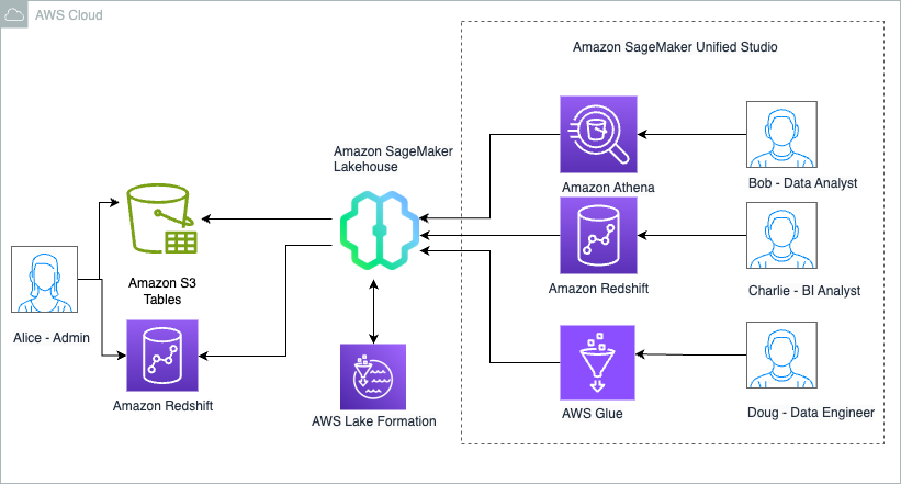
Pratik Das is a Senior Product Manager with AWS Lake Formation. He is passionate about all things data and works with customers to understand their requirements and build delightful experiences. He has a background in building data-driven solutions and machine learning systems in production.