Post Syndicated from Patrick Viker original https://aws.amazon.com/blogs/messaging-and-targeting/monitoring-aws-end-user-messaging-sms-registrations-with-lambda/
Managing AWS End User Messaging SMS registrations can be challenging, especially when dealing with multiple registrations in various states and countries. This post introduces an automated monitoring solution that helps you stay on top of your registration statuses. By leveraging AWS Lambda, EventBridge, and Simple Email Service (SES), you’ll create a system that provides regular updates about registrations that need attention, are under review, in draft pending submission, or have recently been completed.
Whether you’re managing Sender IDs, United States 10DLC campaigns, toll-free numbers, or short codes, this solution will help you maintain visibility across all your registrations and respond promptly to status changes. The setup takes approximately 15-20 minutes and requires no ongoing maintenance beyond occasional adjustments to meet your evolving needs.
Estimated Setup Time: 15-20 minutes
Prerequisites
- An AWS account with access to Lambda, IAM, EventBridge, End User Messaging SMS, and SES
- A verified email address in Amazon SES for sending reports.

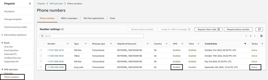
Figure 1: AWS End User Messaging SMS registrations in the console. This view shows registrations in various states that our Lambda function will monitor.
Step 1: Set up Amazon SES
- Open the Amazon SES console
- Navigate to “Verified identities”
- If you have an identity verified you can skip this section
- If you do not already have an identity verified Click “Create identity”
- Review this post to learn how to verify an identity
NOTE: Best practice is to verify a domain identity. This will authenticate your domain and improve deliverability. An email address identity, while more simple, will not be authenticated through DKIM which may decrease deliverability.
Reference: Creating and verifying identities in Amazon SES
Step 2: Create an IAM Role
- Open the IAM console
- Navigate to “Roles” and click “Create role”
- Select “AWS service” and “Lambda” as the use case
- Add only the following AWS managed policy: AWSLambdaBasicExecutionRole
- Name the role (e.g., “EndUserMessagingRegistrationsMonitorRole”) and click “Create role”
- After role creation, click on the newly created role
- Select “Add permissions” → “Create inline policy”
- Click on the “JSON” tab and paste the following policy:
{ "Version": "2012-10-17", "Statement": [ { "Effect": "Allow", "Action": [ "sms-voice:DescribeRegistrations", "sms-voice:DescribeRegistrationVersions" ], "Resource": "arn:aws:sms-voice:${region}:${account-id}:registration/*" }, { "Effect": "Allow", "Action": "ses:SendRawEmail", "Resource": [ "arn:aws:ses:${region}:${account-id}:identity/${domain}", "arn:aws:ses:${region}:${account-id}:configuration-set/*" ], "Condition": { "StringLike": { "ses:FromAddress": [ "*@${domain}" ] } } } ] } - Replace the placeholders in the policy:
- ${region}: Your AWS region (e.g., ‘us-west-2’)
- ${account-id}: Your AWS account ID
- ${domain}: Your verified SES domain
- Click “Next”
- Name the policy (e.g., “EndUserMessagingRegistrationsAccess”) and click “Create policy”
Reference: Creating a role for an AWS service (console)
Step 3: Create the Lambda Function
- Open the Lambda console
- Click “Create function”
- Choose “Author from scratch”
- Configure basic settings:
- Name: EndUserMessagingRegistrationsMonitor
- Runtime: Python 3.12
- Architecture: x86_64
- Permissions: Use the IAM role created in Step 2
- Click “Create function”
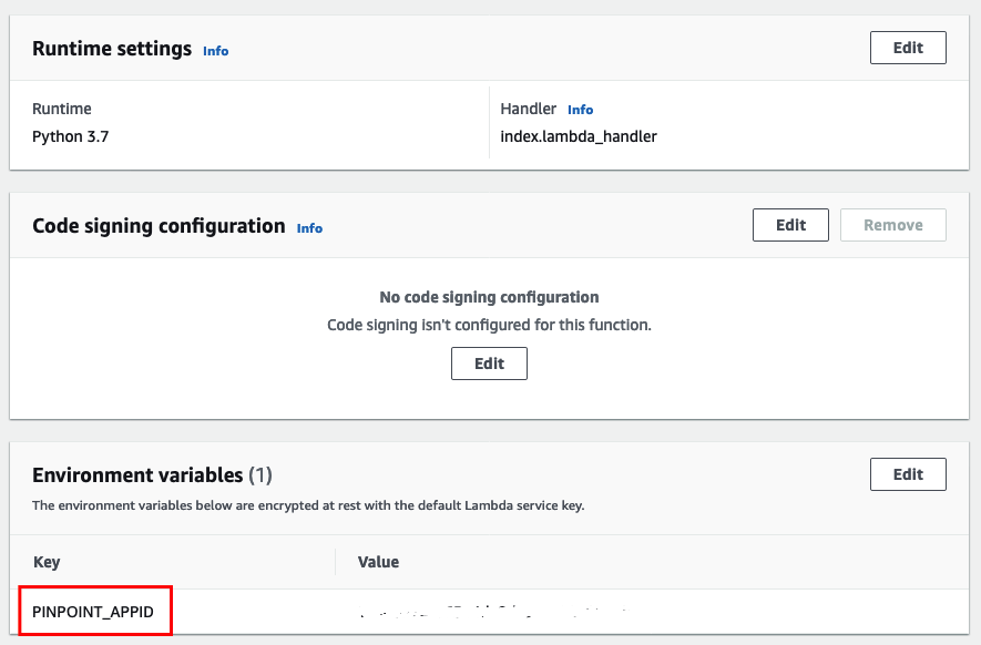
- Configure environment variables:
- Under “Configuration” tab → “Environment variables”
- Set the following key/value pairs:
- Key: SENDER_EMAIL, Value: [Your verified SES email]
- Key: RECIPIENT_EMAIL, Value: [Email to receive reports]
- Configure function timeout:
- Under “Configuration” → “General configuration”
- Set timeout to 1 minute
- In the function code area, paste the following code:
import boto3 import json from datetime import datetime, timedelta from collections import defaultdict from email.mime.text import MIMEText from email.mime.multipart import MIMEMultipart import os # Constants REGION = os.environ['AWS_REGION'] SENDER_EMAIL = os.environ['SENDER_EMAIL'] RECIPIENT_EMAIL = os.environ['RECIPIENT_EMAIL'] COMPLETED_LOOKBACK_DAYS = 7 # Initialize AWS clients sms_client = boto3.client('pinpoint-sms-voice-v2', region_name=REGION) ses_client = boto3.client('ses', region_name=REGION) # Global registration dictionary registrations = { 'REQUIRES_UPDATES': defaultdict(list), 'CREATED': defaultdict(list), 'COMPLETED': defaultdict(list), 'REVIEWING': defaultdict(list) } def get_console_url(registration_id): return f"https://{REGION}.console.aws.amazon.com/sms-voice/home?region={REGION}#/registrations?registration-id={registration_id}" def get_version_details(registration_id, latest_denied_version=None): try: if latest_denied_version: response = sms_client.describe_registration_versions( RegistrationId=registration_id, VersionNumbers=[latest_denied_version] ) else: response = sms_client.describe_registration_versions( RegistrationId=registration_id, MaxResults=1 ) if response['RegistrationVersions']: return response['RegistrationVersions'][0] except Exception as e: print(f"Error getting version details for {registration_id}: {str(e)}") return None def is_recently_completed(version_info): if 'RegistrationVersionStatusHistory' in version_info: history = version_info['RegistrationVersionStatusHistory'] if 'ApprovedTimestamp' in history: approved_time = history['ApprovedTimestamp'] if isinstance(approved_time, datetime): approved_time = approved_time.timestamp() lookback_time = (datetime.now() - timedelta(days=COMPLETED_LOOKBACK_DAYS)).timestamp() return approved_time > lookback_time return False def categorize_registration_type(registration_type): if 'TEN_DLC' in registration_type: return 'TEN_DLC' elif 'LONG_CODE' in registration_type: return 'LONG_CODE' elif 'SHORT_CODE' in registration_type: return 'SHORT_CODE' elif 'SENDER_ID' in registration_type: return 'SENDER_ID' elif 'TOLL_FREE' in registration_type: return 'TOLL_FREE' else: return 'OTHER' def categorize_registrations(): global registrations registrations = { 'REQUIRES_UPDATES': defaultdict(list), 'CREATED': defaultdict(list), 'COMPLETED': defaultdict(list), 'REVIEWING': defaultdict(list) } try: response = sms_client.describe_registrations() for registration in response.get('Registrations', []): status = registration['RegistrationStatus'] registration_id = registration['RegistrationId'] registration_type = registration['RegistrationType'] category = categorize_registration_type(registration_type) reg_info = { 'id': registration_id, 'type': registration_type, 'status': status, 'version': registration['CurrentVersionNumber'], 'console_url': get_console_url(registration_id) } if 'AdditionalAttributes' in registration: reg_info['additional_attributes'] = registration['AdditionalAttributes'] if status == 'REQUIRES_UPDATES': latest_denied_version = registration.get('LatestDeniedVersionNumber') version_info = get_version_details(registration_id, latest_denied_version) if version_info and 'DeniedReasons' in version_info: reg_info['denial_reasons'] = version_info['DeniedReasons'] registrations['REQUIRES_UPDATES'][category].append(reg_info) elif status == 'CREATED': registrations['CREATED'][category].append(reg_info) elif status == 'REVIEWING': registrations['REVIEWING'][category].append(reg_info) elif status == 'COMPLETE': version_info = get_version_details(registration_id) if version_info and is_recently_completed(version_info): approved_timestamp = version_info['RegistrationVersionStatusHistory']['ApprovedTimestamp'] if isinstance(approved_timestamp, datetime): approved_timestamp = approved_timestamp.timestamp() reg_info['approved_timestamp'] = approved_timestamp registrations['COMPLETED'][category].append(reg_info) except Exception as e: print(f"Error listing registrations: {str(e)}") raise e def generate_html_output(): html = """ <html> <head> <style> body { font-family: Arial, sans-serif; margin: 20px; line-height: 1.6; } .registration-group { margin: 20px 0; } .registration-category { background-color: #f0f0f0; padding: 10px; margin: 10px 0; border-radius: 5px; } .registration-item { border-left: 4px solid #ccc; margin: 10px 0; padding: 10px; background-color: #ffffff; } .requires-updates { border-left-color: #ff9900; } .created { border-left-color: #007bff; } .completed { border-left-color: #28a745; } .reviewing { border-left-color: #6c757d; } .denial-reasons { background-color: #fff3f3; padding: 10px; margin: 5px 0; border-radius: 3px; } .console-link { color: #007bff; text-decoration: none; padding: 2px 5px; border: 1px solid #007bff; border-radius: 3px; } .console-link:hover { background-color: #007bff; color: #ffffff; } .summary { margin: 20px 0; padding: 15px; background-color: #e9ecef; border-radius: 5px; box-shadow: 0 2px 4px rgba(0,0,0,0.1); } .divider { border-top: 2px solid #dee2e6; margin: 20px 0; } .lookback-info { background-color: #e2e3e5; padding: 10px; border-radius: 5px; margin: 10px 0; font-style: italic; } h2, h3, h4 { color: #333; margin-top: 20px; } ul { margin: 5px 0; padding-left: 20px; } li { margin: 5px 0; } </style> </head> <body> """ html += f"<h2>Registration Status Report - {datetime.now().strftime('%Y-%m-%d %H:%M:%S')}</h2>" html += f""" <div class="lookback-info"> Note: Completed registrations shown are those completed within the last {COMPLETED_LOOKBACK_DAYS} days. </div> """ html += '<div class="summary"><h3>Summary</h3>' for status, categories in registrations.items(): total = sum(len(regs) for regs in categories.values()) html += f"<p><strong>{status}:</strong> {total}" if status == 'COMPLETED': html += f" (last {COMPLETED_LOOKBACK_DAYS} days)" html += "<br>" for category, regs in categories.items(): if regs: html += f" {category}: {len(regs)}<br>" html += "</p>" grand_total = sum(sum(len(regs) for regs in categories.values()) for categories in registrations.values()) html += f"<p><strong>Total Registrations:</strong> {grand_total}</p>" html += "</div>" html += '<div class="divider"></div>' html += "<h3>Detailed Registration Status</h3>" for status, categories in registrations.items(): total = sum(len(regs) for regs in categories.values()) html += f""" <div class="registration-group"> <h3>{status} Registrations (Total: {total})</h3> """ for category, regs in categories.items(): if regs: html += f""" <div class="registration-category"> <h4>{category} Registrations ({len(regs)})</h4> """ for reg in regs: css_class = status.lower().replace('_', '-') html += f""" <div class="registration-item {css_class}"> <strong>Registration ID:</strong> {reg['id']}<br> <strong>Type:</strong> {reg['type']}<br> <strong>Status:</strong> {reg['status']}<br> <strong>Version:</strong> {reg['version']}<br> <strong>Console:</strong> <a href="{reg['console_url']}" class="console-link" target="_blank">Open in Console</a><br> """ if (reg['type'] == 'US_TEN_DLC_BRAND_VETTING' and status == 'COMPLETED' and 'additional_attributes' in reg and 'VETTING_SCORE' in reg['additional_attributes']): html += f"<strong>Vetting Score:</strong> {reg['additional_attributes']['VETTING_SCORE']}<br>" if status == 'REQUIRES_UPDATES' and reg.get('denial_reasons'): html += '<div class="denial-reasons"><strong>Denial Reasons:</strong><ul>' for reason in reg['denial_reasons']: html += f""" <li> <strong>{reason.get('Reason', 'N/A')}</strong><br> {reason.get('ShortDescription', 'N/A')}<br> """ if reason.get('LongDescription'): html += f"{reason['LongDescription']}<br>" if reason.get('DocumentationLink'): html += f'<a href="{reason["DocumentationLink"]}" target="_blank">Documentation</a>' html += "</li>" html += "</ul></div>" if status == 'COMPLETED': approved_time = datetime.fromtimestamp(reg['approved_timestamp']).strftime('%Y-%m-%d %H:%M:%S') html += f"<strong>Approved:</strong> {approved_time}<br>" html += "</div>" html += "</div>" html += "</div>" html += "</body></html>" return html def send_email(html_content, subject, recipient): msg = MIMEMultipart('mixed') msg['Subject'] = subject msg['From'] = SENDER_EMAIL msg['To'] = recipient html_part = MIMEText(html_content, 'html') msg.attach(html_part) try: response = ses_client.send_raw_email( Source=msg['From'], Destinations=[recipient], RawMessage={'Data': msg.as_string()} ) print(f"Email sent! Message ID: {response['MessageId']}") except Exception as e: print(f"Error sending email: {str(e)}") raise e def lambda_handler(event, context): try: print("Starting registration categorization...") categorize_registrations() print("Generating HTML report...") html_content = generate_html_output() print("Sending email...") subject = f"End User Messaging SMS Registration Status Report - {datetime.now().strftime('%Y-%m-%d %H:%M')}" send_email(html_content, subject, RECIPIENT_EMAIL) return {'statusCode': 200, 'body': json.dumps('Registration status report generated and sent successfully')} except Exception as e: print(f"Error in lambda execution: {str(e)}") return {'statusCode': 500, 'body': json.dumps(f'Error generating report: {str(e)}')}
Reference: Building Lambda functions with Python
Step 4: Set Up EventBridge Rule
- Open the Amazon EventBridge console
- Click “Create rule”
- Name your rule (e.g., “EndUserMessagingRegistrationsMonitorSchedule”)
- For the event pattern, choose “Schedule” then select “Continue in EventBridge Scheduler”
- Configure your schedule pattern to your requirements (for example, Cron-based schedule to run at specific days and times or rate-based schedule such as every 1 day). Click “Next”.
- Select “Lambda” for “Target detail” and select the Lambda function created in Step 3 as the target from the dropdown. Click “Next”.
- For permissions:
- Select “Create new role for this schedule”
- EventBridge will automatically create a role with the necessary permissions to invoke your Lambda function
- Click “Next” to review your configuration
- Click “Create schedule”
Reference: Amazon EventBridge Scheduler
Step 5: Test the Setup
- Open the Lambda console and navigate to your function
- Click “Test” and create a test event (you can use an empty JSON object {})
- Run the test and check the execution results
- Verify that you receive an email report
Reference: Testing Lambda functions in the console

Figure 2: The generated email report provides a clear summary of all registrations, categorized by their status.
Understanding the Lambda Function
Let’s break down the key components of our Lambda function:
- Initialization: The script sets up necessary AWS clients and defines constants.
- categorize_registrations(): This function fetches all registrations and categorizes them based on their status and type.
- generate_html_output(): Creates a formatted HTML report of the registration statuses.
- send_email(): Uses Amazon SES to send the HTML report via email.
- lambda_handler(): The main entry point for the Lambda function, orchestrating the entire process.
The function categorizes registrations into four main statuses:
- REQUIRES_UPDATES: Registrations that need attention or modifications
- CREATED: Newly created registrations
- REVIEWING: Registrations currently under review
- COMPLETED: Registrations that have been approved recently (within the last 7 days by default)

Figure 3: Detailed view of a registration requiring updates and created registrations pending submission, including specific denial reasons if applicable and direct console links.
Customization Options
- Lookback Period: Modify the
COMPLETED_LOOKBACK_DAYSconstant to change how far back the function checks for completed registrations. - Email Formatting: Adjust the HTML and CSS in
generate_html_output()to customize the email report’s appearance. - Additional Data: Modify the
reg_infodictionary incategorize_registrations()to include more data fields in your report.
Monitoring and Maintenance
- CloudWatch Logs: Regularly check the Lambda function’s CloudWatch Logs for any errors or unexpected behavior.
- Adjusting Schedule: If you find the current schedule doesn’t meet your needs, adjust the EventBridge rule accordingly.
Conclusion
You now have an automated system that monitors your End User Messaging SMS registrations and sends you regular, detailed status reports. This setup provides:
- Automated visibility into registrations requiring updates or attention
- Clear tracking of draft registrations awaiting your submission
- Monitoring of registrations under review
- Notifications of recently completed registrations
- A consolidated view of all registration states through formatted email reports
This automated solution eliminates the need for manual status checking and helps ensure timely responses to registration changes. As your messaging needs grow, you can easily customize the monitoring frequency, lookback period, and report format to match your requirements.
Next Steps:
- Consider adjusting the EventBridge schedule based on your registration volume
- Customize the email format to highlight information most relevant to your team
- Set up CloudWatch alarms to monitor the Lambda function’s health
- Review and update the completed registrations lookback period as needed
For more complex scenarios, consider extending this solution with additional features like Slack notifications, registration metrics tracking, or integration with your ticketing system.


 ” width=”1252″ height=”889″>
 ” width=”1280″ height=”720″>
 ” width=”863″ height=”521″>
 ” width=”865″ height=”582″>
 ” width=”1497″ height=”1173″>
 ” width=”1336″ height=”1313″>
 ” width=”1333″ height=”1364″>


 Satyasovan Tripathy works as a Senior Specialist Solution Architect at AWS. He is situated in Bengaluru, India, and focuses on the AWS Digital User Engagement product portfolio. He enjoys reading and travelling outside of work.
 Nikhil Khokhar is a Solutions Architect at AWS. He specializes in building and supporting data streaming solutions that help customers analyze and get value out of their data. In his free time, he makes use of his 3D printing skills to solve everyday problems.


 Rajdeep Tarat is a Senior Solutions Architect at AWS. He lives in Bengaluru, India and helps customers architect and optimize applications on AWS. In his spare time, he enjoys music, programming, and reading.


Response:
3) Send test message
Response:
Response – (ConflictException):
Conclusion
As SMS messaging continues to play a crucial role in customer engagement and authentication, protecting your communications from AIT is more important than ever. Amazon Pinpoint Protect provides a powerful and user-friendly solution to help you mitigate the impact of SMS pumping, ensuring the integrity of your SMS channels and preserving your business’ reputation and resources. Whether you’re a small business or a large enterprise, Pinpoint Protect is a valuable tool to have in your arsenal as you navigate the evolving landscape of SMS messaging.
To get started with Pinpoint SMS Protect, visit the Amazon Pinpoint SMS documentation or reach out to your AWS account team. And don’t forget to let us know in the comments how Protect configurations has helped you combat AIT and strengthen your SMS communications.
A few resources to help you plan for your SMS program:
About the Author
Brett Ezell is your friendly neighborhood Solutions Architect at AWS, where he specializes in helping customers optimize their SMS and email campaigns using Amazon Pinpoint and Amazon Simple Email Service. As a former US Navy veteran, Brett brings a unique perspective to his work, ensuring customers receive tailored solutions to meet their needs. In his free time, Brett enjoys live music, collecting vinyl, and the challenges of a good workout. And, as a self-proclaimed comic book aficionado, he can often be found combing through his local shop for new books to add to his collection.