Tag Archives: EC2

Magic Cloud Networking simplifies security, connectivity, and management of public clouds

Post Syndicated from Steve Welham original https://blog.cloudflare.com/introducing-magic-cloud-networking


Today we are excited to announce Magic Cloud Networking, supercharged by Cloudflare’s recent acquisition of Nefeli Networks’ innovative technology. These new capabilities to visualize and automate cloud networks will give our customers secure, easy, and seamless connection to public cloud environments.

Public clouds offer organizations a scalable and on-demand IT infrastructure without the overhead and expense of running their own datacenter. Cloud networking is foundational to applications that have been migrated to the cloud, but is difficult to manage without automation software, especially when operating at scale across multiple cloud accounts. Magic Cloud Networking uses familiar concepts to provide a single interface that controls and unifies multiple cloud providers’ native network capabilities to create reliable, cost-effective, and secure cloud networks.

Nefeli’s approach to multi-cloud networking solves the problem of building and operating end-to-end networks within and across public clouds, allowing organizations to securely leverage applications spanning any combination of internal and external resources. Adding Nefeli’s technology will make it easier than ever for our customers to connect and protect their users, private networks and applications.

Why is cloud networking difficult?

Compared with a traditional on-premises data center network, cloud networking promises simplicity:

  • Much of the complexity of physical networking is abstracted away from users because the physical and ethernet layers are not part of the network service exposed by the cloud provider.
  • There are fewer control plane protocols; instead, the cloud providers deliver a simplified software-defined network (SDN) that is fully programmable via API.
  • There is capacity — from zero up to very large — available instantly and on-demand, only charging for what you use.

However, that promise has not yet been fully realized. Our customers have described several reasons cloud networking is difficult:

  • Poor end-to-end visibility: Cloud network visibility tools are difficult to use and silos exist even within single cloud providers that impede end-to-end monitoring and troubleshooting.
  • Faster pace: Traditional IT management approaches clash with the promise of the cloud: instant deployment available on-demand. Familiar ClickOps and CLI-driven procedures must be replaced by automation to meet the needs of the business.
  • Different technology: Established network architectures in on-premises environments do not seamlessly transition to a public cloud. The missing ethernet layer and advanced control plane protocols were critical in many network designs.
  • New cost models: The dynamic pay-as-you-go usage-based cost models of the public clouds are not compatible with established approaches built around fixed cost circuits and 5-year depreciation. Network solutions are often architected with financial constraints, and accordingly, different architectural approaches are sensible in the cloud.
  • New security risks: Securing public clouds with true zero trust and least-privilege demands mature operating processes and automation, and familiarity with cloud-specific policies and IAM controls.
  • Multi-vendor: Oftentimes enterprise networks have used single-vendor sourcing to facilitate interoperability, operational efficiency, and targeted hiring and training. Operating a network that extends beyond a single cloud, into other clouds or on-premises environments, is a multi-vendor scenario.

Nefeli considered all these problems and the tensions between different customer perspectives to identify where the problem should be solved.

Trains, planes, and automation

Consider a train system. To operate effectively it has three key layers:

  • tracks and trains
  • electronic signals
  • a company to manage the system and sell tickets.

A train system with good tracks, trains, and signals could still be operating below its full potential because its agents are unable to keep up with passenger demand. The result is that passengers cannot plan itineraries or purchase tickets.

The train company eliminates bottlenecks in process flow by simplifying the schedules, simplifying the pricing, providing agents with better booking systems, and installing automated ticket machines. Now the same fast and reliable infrastructure of tracks, trains, and signals can be used to its full potential.

Solve the right problem

In networking, there are an analogous set of three layers, called the networking planes:

  • Data Plane: the network paths that transport data (in the form of packets) from source to destination.
  • Control Plane: protocols and logic that change how packets are steered across the data plane.
  • Management Plane: the configuration and monitoring interfaces for the data plane and control plane.

In public cloud networks, these layers map to:

  • Cloud Data Plane: The underlying cables and devices are exposed to users as the Virtual Private Cloud (VPC) or Virtual Network (VNet) service that includes subnets, routing tables, security groups/ACLs and additional services such as load-balancers and VPN gateways.
  • Cloud Control Plane: In place of distributed protocols, the cloud control plane is a software defined network (SDN) that, for example, programs static route tables. (There is limited use of traditional control plane protocols, such as BGP to interface with external networks and ARP to interface with VMs.)
  • Cloud Management Plane: An administrative interface with a UI and API which allows the admin to fully configure the data and control planes. It also provides a variety of monitoring and logging capabilities that can be enabled and integrated with 3rd party systems.

Like our train example, most of the problems that our customers experience with cloud networking are in the third layer: the management plane.

Nefeli simplifies, unifies, and automates cloud network management and operations.

Avoid cost and complexity

One common approach to tackle management problems in cloud networks is introducing Virtual Network Functions (VNFs), which are virtual machines (VMs) that do packet forwarding, in place of native cloud data plane constructs. Some VNFs are routers, firewalls, or load-balancers ported from a traditional network vendor’s hardware appliances, while others are software-based proxies often built on open-source projects like NGINX or Envoy. Because VNFs mimic their physical counterparts, IT teams could continue using familiar management tooling, but VNFs have downsides:

  • VMs do not have custom network silicon and so instead rely on raw compute power. The VM is sized for the peak anticipated load and then typically runs 24x7x365. This drives a high cost of compute regardless of the actual utilization.
  • High-availability (HA) relies on fragile, costly, and complex network configuration.
  • Service insertion — the configuration to put a VNF into the packet flow — often forces packet paths that incur additional bandwidth charges.
  • VNFs are typically licensed similarly to their on-premises counterparts and are expensive.
  • VNFs lock in the enterprise and potentially exclude them benefitting from improvements in the cloud’s native data plane offerings.

For these reasons, enterprises are turning away from VNF-based solutions and increasingly looking to rely on the native network capabilities of their cloud service providers. The built-in public cloud networking is elastic, performant, robust, and priced on usage, with high-availability options integrated and backed by the cloud provider’s service level agreement.

In our train example, the tracks and trains are good. Likewise, the cloud network data plane is highly capable. Changing the data plane to solve management plane problems is the wrong approach. To make this work at scale, organizations need a solution that works together with the native network capabilities of cloud service providers.

Nefeli leverages native cloud data plane constructs rather than third party VNFs.

Introducing Magic Cloud Networking

The Nefeli team has joined Cloudflare to integrate cloud network management functionality with Cloudflare One. This capability is called Magic Cloud Networking and with it, enterprises can use the Cloudflare dashboard and API to manage their public cloud networks and connect with Cloudflare One.

End-to-end

Just as train providers are focused only on completing train journeys in their own network, cloud service providers deliver network connectivity and tools within a single cloud account. Many large enterprises have hundreds of cloud accounts across multiple cloud providers. In an end-to-end network this creates disconnected networking silos which introduce operational inefficiencies and risk.

Imagine you are trying to organize a train journey across Europe, and no single train company serves both your origin and destination. You know they all offer the same basic service: a seat on a train. However, your trip is difficult to arrange because it involves multiple trains operated by different companies with their own schedules and ticketing rates, all in different languages!

Magic Cloud Networking is like an online travel agent that aggregates multiple transportation options, books multiple tickets, facilitates changes after booking, and then delivers travel status updates.

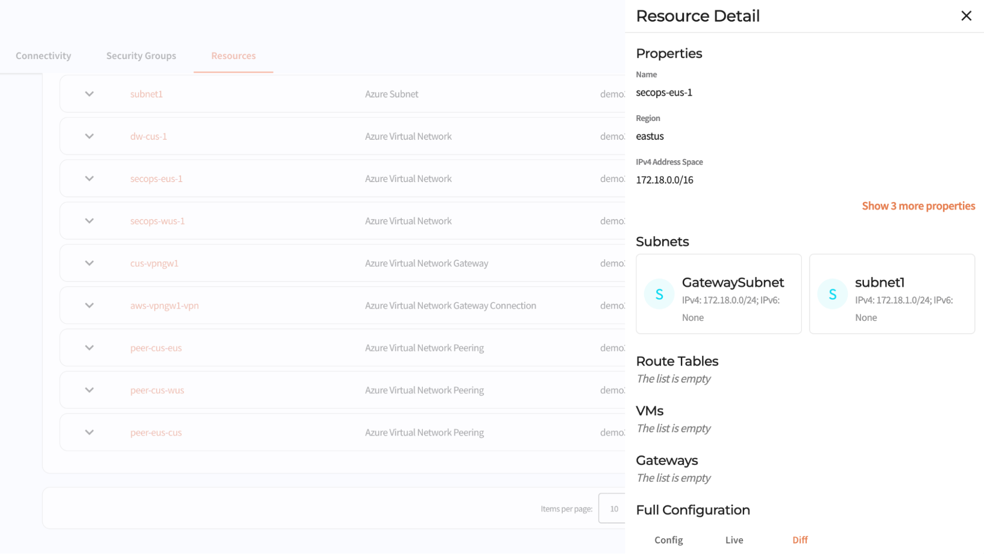
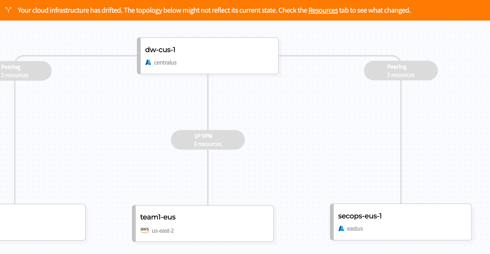
Through the Cloudflare dashboard, you can discover all of your network resources across accounts and cloud providers and visualize your end-to-end network in a single interface. Once Magic Cloud Networking discovers your networks, you can build a scalable network through a fully automated and simple workflow.

Resource inventory shows all configuration in a single and responsive UI

Taming per-cloud complexity

Public clouds are used to deliver applications and services. Each cloud provider offers a composable stack of modular building blocks (resources) that start with the foundation of a billing account and then add on security controls. The next foundational layer, for server-based applications, is VPC networking. Additional resources are built on the VPC network foundation until you have compute, storage, and network infrastructure to host the enterprise application and data. Even relatively simple architectures can be composed of hundreds of resources.

The trouble is, these resources expose abstractions that are different from the building blocks you would use to build a service on prem, the abstractions differ between cloud providers, and they form a web of dependencies with complex rules about how configuration changes are made (rules which differ between resource types and cloud providers). For example, say I create 100 VMs, and connect them to an IP network. Can I make changes to the IP network while the VMs are using the network? The answer: it depends.

Magic Cloud Networking handles these differences and complexities for you. It configures native cloud constructs such as VPN gateways, routes, and security groups to securely connect your cloud VPC network to Cloudflare One without having to learn each cloud’s incantations for creating VPN connections and hubs.

Continuous, coordinated automation

Returning to our train system example, what if the railway maintenance staff find a dangerous fault on the railroad track? They manually set the signal to a stop light to prevent any oncoming trains using the faulty section of track. Then, what if, by unfortunate coincidence, the scheduling office is changing the signal schedule, and they set the signals remotely which clears the safety measure made by the maintenance crew? Now there is a problem that no one knows about and the root cause is that multiple authorities can change the signals via different interfaces without coordination.

The same problem exists in cloud networks: configuration changes are made by different teams using different automation and configuration interfaces across a spectrum of roles such as billing, support, security, networking, firewalls, database, and application development.

Once your network is deployed, Magic Cloud Networking monitors its configuration and health, enabling you to be confident that the security and connectivity you put in place yesterday is still in place today. It tracks the cloud resources it is responsible for, automatically reverting drift if they are changed out-of-band, while allowing you to manage other resources, like storage buckets and application servers, with other automation tools. And, as you change your network, Cloudflare takes care of route management, injecting and withdrawing routes globally across Cloudflare and all connected cloud provider networks.

Magic Cloud Networking is fully programmable via API, and can be integrated into existing automation toolchains.

The interface warns when cloud network infrastructure drifts from intent

Ready to start conquering cloud networking?

We are thrilled to introduce Magic Cloud Networking as another pivotal step to fulfilling the promise of the Connectivity Cloud. This marks our initial stride in empowering customers to seamlessly integrate Cloudflare with their public clouds to get securely connected, stay securely connected, and gain flexibility and cost savings as they go.

Join us on this journey for early access: learn more and sign up here.

Get the full benefits of IMDSv2 and disable IMDSv1 across your AWS infrastructure

Post Syndicated from Saju Sivaji original https://aws.amazon.com/blogs/security/get-the-full-benefits-of-imdsv2-and-disable-imdsv1-across-your-aws-infrastructure/

The Amazon Elastic Compute Cloud (Amazon EC2) Instance Metadata Service (IMDS) helps customers build secure and scalable applications. IMDS solves a security challenge for cloud users by providing access to temporary and frequently-rotated credentials, and by removing the need to hardcode or distribute sensitive credentials to instances manually or programmatically. The Instance Metadata Service Version 2 (IMDSv2) adds protections; specifically, IMDSv2 uses session-oriented authentication with the following enhancements:

  • IMDSv2 requires the creation of a secret token in a simple HTTP PUT request to start the session, which must be used to retrieve information in IMDSv2 calls.
  • The IMDSv2 session token must be used as a header in subsequent IMDSv2 requests to retrieve information from IMDS. Unlike a static token or fixed header, a session and its token are destroyed when the process using the token terminates. IMDSv2 sessions can last up to six hours.
  • A session token can only be used directly from the EC2 instance where that session began.
  • You can reuse a token or create a new token with every request.
  • Session token PUT requests are blocked if they contain an X-forwarded-for header.

In a previous blog post, we explained how these new protections add defense-in-depth for third-party and external application vulnerabilities that could be used to try to access the IMDS.

You won’t be able to get the full benefits of IMDSv2 until you disable IMDSv1. While IMDS is provided by the instance itself, the calls to IMDS are from your software. This means your software must support IMDSv2 before you can disable IMDSv1. In addition to AWS SDKs, CLIs, and tools like the SSM agents supporting IMDSv2, you can also use the IMDS Packet Analyzer to pinpoint exactly what you need to update to get your instances ready to use only IMDSv2. These tools make it simpler to transition to IMDSv2 as well as launch new infrastructure with IMDSv1 disabled. All instances launched with AL2023 set the instance to provide only IMDSv2 (IMDSv1 is disabled) by default, with AL2023 also not making IMDSv1 calls.

AWS customers who want to get the benefits of IMDSv2 have told us they want to use IMDSv2 across both new and existing, long-running AWS infrastructure. This blog post shows you scalable solutions to identify existing infrastructure that is providing IMDSv1, how to transition to IMDSv2 on your infrastructure, and how to completely disable IMDSv1. After reviewing this blog, you will be able to set new Amazon EC2 launches to IMDSv2. You will also learn how to identify existing software making IMDSv1 calls, so you can take action to update your software and then require IMDSv2 on existing EC2 infrastructure.

Identifying IMDSv1-enabled EC2 instances

The first step in transitioning to IMDSv2 is to identify all existing IMDSv1-enabled EC2 instances. You can do this in various ways.

Using the console

You can identify IMDSv1-enabled instances using the IMDSv2 attribute column in the Amazon EC2 page in the AWS Management Console.

To view the IMDSv2 attribute column:

  1. Open the Amazon EC2 console and go to Instances.
  2. Choose the settings icon in the top right.
  3. Scroll down to IMDSv2, turn on the slider.
  4. Choose Confirm.

This gives you the IMDS status of your instances. A status of optional means that IMDSv1 is enabled on the instance and required means that IMDSv1 is disabled.

Figure 1: Example of IMDS versions for EC2 instances in the console

Figure 1: Example of IMDS versions for EC2 instances in the console

Using the AWS CLI

You can identify IMDSv1-enabled instances using the AWS Command Line Interface (AWS CLI) by running the aws ec2 describe-instances command and checking the value of HttpTokens. The HttpTokens value determines what version of IMDS is enabled, with optional enabling IMDSv1 and IMDSv2 and required means IMDSv2 is required. Similar to using the console, the optional status indicates that IMDSv1 is enabled on the instance and required indicates that IMDSv1 is disabled.

"MetadataOptions": {
                        "State": "applied", 
                        "HttpEndpoint": "enabled", 
                        "HttpTokens": "optional", 
                        "HttpPutResponseHopLimit": 1
                    },

[ec2-user@ip-172-31-24-101 ~]$ aws ec2 describe-instances | grep '"HttpTokens": "optional"' | wc -l
4

Using AWS Config

AWS Config continually assesses, audits, and evaluates the configurations and relationships of your resources on AWS, on premises, and on other clouds. The AWS Config rule ec2-imdsv2-check checks whether your Amazon EC2 instance metadata version is configured with IMDSv2. The rule is NON_COMPLIANT if the HttpTokens is set to optional, which means the EC2 instance has IMDSv1 enabled.

Figure 2: Example of noncompliant EC2 instances in the AWS Config console

Figure 2: Example of noncompliant EC2 instances in the AWS Config console

After this AWS Config rule is enabled, you can set up AWS Config notifications through Amazon Simple notification Service (Amazon SNS).

Using Security Hub

AWS Security Hub provides detection and alerting capability at the account and organization levels. You can configure cross-Region aggregation in Security Hub to gain insight on findings across Regions. If using AWS Organizations, you can configure a Security Hub designated account to aggregate findings across accounts in your organization.

Security Hub has an Amazon EC2 control ([EC2.8] Amazon EC2 instances should use Instance Metadata Service Version 2 (IMDSv2)) that uses the AWS Config rule ec2-imdsv2-check to check if the instance metadata version is configured with IMDSv2. The rule is NON_COMPLIANT if the HttpTokens is set to optional, which means EC2 instance has IMDSv1 enabled.

Figure 3: Example of AWS Security Hub showing noncompliant EC2 instances

Figure 3: Example of AWS Security Hub showing noncompliant EC2 instances

Using Amazon Event Bridge, you can also set up alerting for the Security Hub findings when the EC2 instances are noncompliant for IMDSv2.

{
  "source": ["aws.securityhub"],
  "detail-type": ["Security Hub Findings - Imported"],
  "detail": {
    "findings": {
      "ProductArn": ["arn:aws:securityhub:us-west-2::product/aws/config"],
      "Title": ["ec2-imdsv2-check"]
    }
  }
}

Identifying if EC2 instances are making IMDSv1 calls

Not all of your software will be making IMDSv1 calls; your dependent libraries and tools might already be compatible with IMDSv2. However, to mitigate against compatibility issues in requiring IMDSv2 and disabling IMDSv1 entirely, you must check for remaining IMDSv1 calls from your software. After you’ve identified that there are instances with IMDSv1 enabled, investigate if your software is making IMDSv1 calls. Most applications make IMDSv1 calls at instance launch and shutdown. For long running instances, we recommend monitoring IMDSv1 calls during a launch or a stop and restart cycle.

You can check whether your software is making IMDSv1 calls by checking the MetadataNoToken metric in Amazon CloudWatch. You can further identify the source of IMDSv1 calls by using the IMDS Packet Analyzer tool.

Steps to check IMDSv1 usage with CloudWatch

  1. Open the CloudWatch console.
  2. Go to Metrics and then All Metrics.
  3. Select EC2 and then choose Per-Instance Metrics.
  4. Search and add the Metric MetadataNoToken for the instances you’re interested in.
Figure 4: CloudWatch dashboard for MetadataNoToken per-instance metric

Figure 4: CloudWatch dashboard for MetadataNoToken per-instance metric

You can use expressions in CloudWatch to view account wide metrics.

SEARCH('{AWS/EC2,InstanceId} MetricName="MetadataNoToken"', 'Maximum')
Figure 5: Using CloudWatch expressions to view account wide metrics for MetadataNoToken

Figure 5: Using CloudWatch expressions to view account wide metrics for MetadataNoToken

You can combine SEARCH and SORT expressions in CloudWatch to help identify the instances using IMDSv1.

SORT(SEARCH('{AWS/EC2,InstanceId} MetricName="MetadataNoToken"', 'Sum', 300), SUM, DESC, 10)
Figure 6: Another example of using CloudWatch expressions to view account wide metrics

Figure 6: Another example of using CloudWatch expressions to view account wide metrics

If you have multiple AWS accounts or use AWS Organizations, you can set up a centralized monitoring account using CloudWatch cross account observability.

IMDS Packet Analyzer

The IMDS Packet Analyzer is an open source tool that identifies and logs IMDSv1 calls from your software, including software start-up on your instance. This tool can assist in identifying the software making IMDSv1 calls on EC2 instances, allowing you to pinpoint exactly what you need to update to get your software ready to use IMDSv2. You can run the IMDS Packet Analyzer from a command line or install it as a service. For more information, see IMDS Packet Analyzer on GitHub.

Disabling IMDSv1 and maintaining only IMDSv2 instances

After you’ve monitored and verified that the software on your EC2 instances isn’t making IMDSv1 calls, you can disable IMDSv1 on those instances. For all compatible workloads, we recommend using Amazon Linux 2023, which offers several improvements (see launch announcement), including requiring IMDSv2 (disabling IMDSv1) by default.

You can also create and modify AMIs and EC2 instances to disable IMDSv1. Configure the AMI provides guidance on how to register a new AMI or change an existing AMI by setting the imds-support parameter to v2.0. If you’re using container services (such as ECS or EKS), you might need a bigger hop limit to help avoid falling back to IMDSv1. You can use the modify-instance-metadata-options launch parameter to make the change. We recommend testing with a hop limit of three in container environments.

To create a new instance

For new instances, you can disable IMDSv1 and enable IMDSv2 by specifying the metadata-options parameter using the run-instance CLI command.

aws ec2 run-instances
    --image-id <ami-0123456789example>
    --instance-type c3.large
    --metadata-options “HttpEndpoint=enabled,HttpTokens=required”

To modify the running instance

aws ec2 modify-instance-metadata-options \
--instance-id <instance-0123456789example> \
--http-tokens required \
--http-endpoint enabled

To configure a new AMI

aws ec2 register-image \
    --name <my-image> \
    --root-device-name /dev/xvda \
    --block-device-mappings DeviceName=/dev/xvda,Ebs={SnapshotId=<snap-0123456789example>} \
    --imds-support v2.0

To modify an existing AMI

aws ec2 modify-image-attribute \
    --image-id <ami-0123456789example> \
    --imds-support v2.0

Using the console

If you’re using the console to launch instances, after selecting Launch Instance from AWS Console, choose the Advanced details tab, scroll down to Metadata version and select V2 only (token required).

Figure 7: Modifying IMDS version using the console

Figure 7: Modifying IMDS version using the console

Using EC2 launch templates

You can use an EC2 launch template as an instance configuration template that an Amazon Auto Scaling group can use to launch EC2 instances. When creating the launch template using the console, you can specify the Metadata version and select V2 only (token required).

Figure 8: Modifying the IMDS version in the EC2 launch templates

Figure 8: Modifying the IMDS version in the EC2 launch templates

Using CloudFormation with EC2 launch templates

When creating an EC2 launch template using AWS CloudFormation, you must specify the MetadataOptions property to use only IMDSv2 by setting HttpTokens as required.

In this state, retrieving the AWS Identity and Access Management (IAM) role credentials always returns IMDSv2 credentials; IMDSv1 credentials are not available.

{
"HttpEndpoint" : <String>,
"HttpProtocolIpv6" : <String>,
"HttpPutResponseHopLimit" : <Integer>,
"HttpTokens" : required,
"InstanceMetadataTags" : <String>
}

Using Systems Manager automation runbook

You can run the EnforceEC2InstanceIMDSv2 automation document available in AWS Systems Manager, which will enforce IMDSv2 on the EC2 instance using the ModifyInstanceMetadataOptions API.

  1. Open the Systems Manager console, and then select Automation from the navigation pane.
  2. Choose Execute automation.
  3. On the Owned by Amazon tab, for Automation document, enter EnforceEC2InstanceIMDSv2, and then press Enter.
  4. Choose EnforceEC2InstanceIMDSv2 document, and then choose Next.
  5. For Execute automation document, choose Simple execution.

    Note: If you need to run the automation on multiple targets, then choose Rate Control.

  6. For Input parameters, enter the ID of EC2 instance under InstanceId
  7. For AutomationAssumeRole, select a role.

    Note: To change the target EC2 instance, the AutomationAssumeRole must have ec2:ModifyInstanceMetadataOptions and ec2:DescribeInstances permissions. For more information about creating the assume role for Systems Manager Automation, see Create a service role for Automation.

  8. Choose Execute.

Using the AWS CDK

If you use the AWS Cloud Development Kit (AWS CDK) to launch instances, you can use it to set the requireImdsv2 property to disable IMDSv1 and enable IMDSv2.

new ec2.Instance(this, 'Instance', {
        // <... other parameters>
        requireImdsv2: true,
})

Using AWS SDK

The new clients for AWS SDK for Java 2.x use IMDSv2, and you can use the new clients to retrieve instance metadata for your EC2 instances. See Introducing a new client in the AWS SDK for Java 2.x for retrieving EC2 Instance Metadata for instructions.

Maintain only IMDSv2 EC2 instances

To maintain only IMDSv2 instances, you can implement service control policies and IAM policies that verify that users and software on your EC2 instances can only use instance metadata using IMDSv2. This policy specifies that RunInstance API calls require the EC2 instance use only IMDSv2. We recommend implementing this policy after all of the instances in associated accounts are free of IMDSv1 calls and you have migrated all of the instances to use only IMDSv2.

{
    "Version": "2012-10-17",
    "Statement": [
               {
            "Sid": "RequireImdsV2",
            "Effect": "Deny",
            "Action": "ec2:RunInstances",
            "Resource": "arn:aws:ec2:*:*:instance/*",
            "Condition": {
                "StringNotEquals": {
                    "ec2:MetadataHttpTokens": "required"
                }
            }
        }
    ]
} 

You can find more details on applicable service control policies (SCPs) and IAM policies in the EC2 User Guide.

Restricting credential usage using condition keys

As an additional layer of defence, you can restrict the use of your Amazon EC2 role credentials to work only when used in the EC2 instance to which they are issued. This control is complementary to IMDSv2 since both can work together. The AWS global condition context keys for EC2 credential control properties (aws:EC2InstanceSourceVPC and aws:EC2InstanceSourcePrivateIPv4) restrict the VPC endpoints and private IPs that can use your EC2 instance credentials, and you can use these keys in service control policies (SCPs) or IAM policies. Examples of these policies are in this blog post.

Conclusion

You won’t be able to get the full benefits of IMDSv2 until you disable IMDSv1. In this blog post, we showed you how to identify IMDSv1-enabled EC2 instances and how to determine if and when your software is making IMDSv1 calls. We also showed you how to disable IMDSv1 on new and existing EC2 infrastructure after your software is no longer making IMDSv1 calls. You can use these tools to transition your existing EC2 instances, and set your new EC2 launches, to use only IMDSv2.

If you have feedback about this post, submit comments in the Comments section below. If you have questions about this post, start a new thread on the AWS Compute re:Post or contact AWS Support.

Want more AWS Security news? Follow us on Twitter.

Saju Sivaji

Saju Sivaji

Saju is Senior Technical Program Manager with the AWS Security organization. When Saju isn’t managing security expectation programs to help raise the security bar for both internal and external customers, he enjoys travelling, racket sports, and bicycling.

Joshua Levinson

Joshua Levinson

Joshua is a Principal Product Manager at AWS on the Amazon EC2 team. He is passionate about helping customers with highly scalable features on EC2 and across AWS and enjoys the challenge of building simplified solutions to complex problems. Outside of work, he enjoys cooking, reading with his kids, and Olympic weightlifting.

How to scan EC2 AMIs using Amazon Inspector

Post Syndicated from Luke Notley original https://aws.amazon.com/blogs/security/how-to-scan-ec2-amis-using-amazon-inspector/

Amazon Inspector is an automated vulnerability management service that continually scans Amazon Web Services (AWS) workloads for software vulnerabilities and unintended network exposure. Amazon Inspector supports vulnerability reporting and deep inspection of Amazon Elastic Compute Cloud (Amazon EC2) instances, container images stored in Amazon Elastic Container Registry (Amazon ECR), and AWS Lambda functions. Operating system and programming language support is extensive, ranging from Bottlerocket to Windows Server.

Many customers use Amazon EC2 Auto Scaling groups as part of their resilience and scaling architecture for their workloads. With Auto Scaling groups, you can scale and deploy rapidly by using Amazon Machine Images (AMIs). However, AMIs within your environment can quickly become outdated as new vulnerabilities are discovered. A security best practice is to perform routine vulnerability assessments of your AMIs to identify whether newfound vulnerabilities apply to them. If you identify a vulnerability, you can update the AMI with the appropriate security patches, test the AMI in lower environments, and deploy the updated AMI in your environment. At this time, Amazon Inspector only supports scanning of running EC2 instances.

In this blog post, we’ll share a solution that you can use with Amazon EventBridge, AWS Lambda, AWS Step Functions, Amazon Simple Notification Service (Amazon SNS)­­, and Amazon Simple Storage Service (Amazon S3) to scan AMIs and generate Amazon Inspector finding reports to help ensure that your AMIs are scanned for known vulnerabilities and updated prior to deployment. Then, we will show you how to periodically scan selected EC2 AMIs based on a tagging strategy, and take automated actions.

Prerequisites

The solution provided in this post has a number of items that you will need to review and address before you deploy the solution:

  1. Make sure that the AMI to be scanned by Amazon Inspector is based from one of the operating systems that AWS supports for EC2 scanning.
  2. To successfully complete a scan, Amazon Inspector requires the EC2 instance to be a managed instance in AWS Systems Manager that has the Systems Manager Agent installed and running, and has an attached AWS Identity and Access Management (IAM) instance profile that allows Systems Manager to manage the instance. For more information, see Scanning Amazon EC2 instances with Amazon Inspector.
  3. If you use customer managed keys to encrypt Amazon Elastic Block Store (Amazon EBS) volumes and you have a default EC2 configuration set to encrypt EBS volumes, you will need to configure additional key policy permissions. For the customer managed key that encrypts EBS volumes, add the following example policy statement to the key policy. Make sure to replace <111122223333> with your own AWS account ID.
    {
                "Sid": "Allow use of the key by AMI Scanner State Machine",
                "Effect": "Allow",
                "Principal": {
                    "AWS": "arn:aws:iam:: <111122223333>:role/service-role/AMIScanner-Statemachine-role"
                },
                "Action": [
                    "kms:Encrypt",
                    "kms:Decrypt",
                    "kms:ReEncrypt*",
                    "kms:GenerateDataKey*",
                    "kms:DescribeKey"
                ],
                "Resource": "*"
            },

    If you don’t add this additional policy, the Step Functions state machine won’t allow the EC2 instances to launch. For more information, see Key policy sections that allow access to the customer managed key.

  4. The solution in this blog post requires that you activate Amazon Inspector in your AWS account. If you haven’t activated Amazon Inspector yet, learn more about the free trial and pricing, and follow the steps in the Amazon Inspector documentation to set up the service and start monitoring your account. Alternatively, you can activate Amazon Inspector by using the AWS Command Line Interface (AWS CLI) and this GitHub example.

Solution overview and architecture

In this solution, you will use the follow AWS services and features:

  • Task orchestration
    • AWS Step Functions state machine workflows are used in this solution to verify that conditions are successfully validated before moving to the next task. This helps ensure that the Amazon Inspector scanning of the temporary instance launched in the first state machine is completed before the second state machine starts. This can help reduce the overall cost of the solution and can help prevent the first state machine from reaching state transition limitations.
    • Lambda functions handle the logic for retrieving AMIs to be scanned, launching temporary instances, creating Amazon EventBridge rules, tagging AMIs, and exporting Amazon Inspector reports to Amazon S3.
  • AMI tagging
    • To use this solution, you need to tag the AMIs that Amazon Inspector will scan, because a Lambda function will use these tags to start the solution orchestration. For this post, we use the tag InspectorScan with a value of true. With AMI tagging, you can configure automated processes as part of your deployment pipelines to implement the tagging.
  • Storage of exported Amazon Inspector findings
    • Amazon S3 helps you store the exported Amazon Inspector findings report and use them in a standardized format for multiple use cases across AWS services, or use Amazon Athena to query the reports, which we will cover later in the post. Each scanned report is stored in the S3 bucket and is named in the form AMI-NAME/guid.JSON or AMI-NAME/guid.CSV, depending on the export format that you specify.
    • You can also use S3 event notifications to alert different operational teams that there are Amazon Inspector scan results that require review.
  • Encryption of Amazon Inspector findings reports
    • AWS Key Management Service (AWS KMS) is used to encrypt the findings report. The AWS KMS key used must be a customer managed, symmetric KMS encryption key, and importantly, the key must be in the same AWS Region as the S3 bucket that you configured to store the report. The solution in this post creates a new KMS key, as well as a key policy that is configured to grant permissions for Amazon Inspector to use the key.
  • Event tracking and scheduling
    • This solution uses an Amazon EventBridge rule to listen for completed Amazon Inspector scan events for each temporary EC2 instance launch. When the EventBridge rule finds a matched event, the rule passes the required parameters and invokes the second Step Functions state machine. The event pattern used in this solution uses the following format:
      	{
      			"source": ["aws.inspector2"],
      			"detail-type": ["Inspector2 Scan"],
      			"resources": ["i-abcdef01234567890"]
      		}

    • You can schedule the AMI scanning by using an EventBridge rule that invokes a Lambda function that runs on a schedule. The Lambda function uses a cron expression to occur weekly. You can configure this parameter according to your requirements. Initially, this rule will be disabled to allow you to configure and enable the rule at a later stage.
    • Amazon SNS sends notifications during the AMI scanning solution process. From the SNS topic, you can configure different subscriptions, depending on your preferred use case and environment. An example of a subscription could be a shared mailbox email address for the security team or incident ticketing system.

Figure 1 shows the solution architecture.

Figure 1: Amazon Inspector scanning of an AMI

Figure 1: Amazon Inspector scanning of an AMI

The high-level workflow of the solution is as follows:

  1. You can use EventBridge to create a scheduled rule to invoke a Lambda function. You can set the rule for daily, weekly, or monthly, depending on your use case.
  2. The Lambda function searches for AMIs with the appropriate tags and passes these as parameters to the Step Functions workflow.
  3. The first Step Functions state machine is invoked for each AMI to be scanned.
  4. The first Step Functions workflow deploys a temporary EC2 instance from the AMI that is defined.
  5. A Lambda function is invoked to create an EventBridge rule.
  6. An EventBridge rule is created to listen for the successful Amazon Inspector scanned event of the temporary EC2 instance.
  7. A Lambda function is invoked to tag the EC2 instance.
  8. The temporary EC2 instance is tagged, showing Amazon Inspector that scanning is in progress.
  9. The first Step Functions workflow sends a notification to an SNS topic.
  10. The EventBridge rule parses the required parameters and invokes the second Step Functions state machine.
  11. A Lambda function is invoked to generate an Amazon Inspector report and export the findings to an S3 bucket.
  12. The scanned Amazon Inspector AMI results are saved to an S3 bucket.
  13. The Step Functions workflow terminates the temporary EC2 instance that can reduce cost and clean up the process.
  14. A Lambda function is invoked to delete the temporary EventBridge rule.
  15. The temporary EventBridge rule and targets are deleted.
  16. A Lambda function is invoked to tag the AMI.
  17. The scanned AMI is updated with tagging metadata.
  18. The second Step Functions workflow sends a final notification to an SNS topic.

Deploy the solution

The solution will be deployed with the scheduled rule in Amazon EventBridge disabled to allow you to create your tagging strategy and to familiarize yourself with the solution. Later in this post, we’ll cover how to enable the Amazon EventBridge scheduled rule.

Step 1: Deploy the CloudFormation template

For this next step, make sure that you deploy the CloudFormation template provided for multi-AMI scanning in the AWS account and Region where you want to test this solution.

To deploy the CloudFormation template

  1. Choose the following Launch Stack button to launch a CloudFormation stack in your account. Note that the stack will launch in the N. Virginia (us-east-1) Region. To deploy this solution into other AWS Regions, download the solution’s CloudFormation template, modify it, and deploy it to the selected Region.

    Select this image to open a link that starts building the CloudFormation stack

    Make sure that you configure the following parameters in the CloudFormation template so that it deploys successfully:

    • AMITagName — The AMI tag name to check if the AMI should be scanned by Amazon Inspector.
    • AMITagValue — The AMI tag value to check if the AMI should be scanned by Amazon Inspector.
    • InspectorReportFormat — The report format, which can be either CSV or JSON.
    • InstanceSubnetID — The subnet ID to launch the temporary EC2 instance into.
    • InstanceType — The instance type to deploy the AMI to for temporary scanning purposes.
    • KmsKeyAdministratorRole — The existing IAM role that needs to have administrator access to the KMS key created for the solution. This key provides access to encrypt and decrypt the Amazon Inspector report.
    • S3ReportBucketName — The name of the S3 bucket to be created.
    • SnsTopic — The name of the new SNS topic to be created. This name defines the SNS topic that notifications are published to.
  2. Review the stack name and the parameters for the template.
  3. On the Quick create stack screen, scroll to the bottom and select I acknowledge that AWS CloudFormation might create IAM resources.
  4. Choose Create stack. The deployment of the CloudFormation stack will take 3–4 minutes.

After the CloudFormation stack has deployed successfully, you can use the deployed solution.

Step 2: Manually run the first Step Functions workflow

The first Step Functions state machine requires parameters to be passed in; the SingleAMI Lambda function accomplishes this. You can start the Lambda function by creating a test event and passing the correct JSON text and parameters. The following parameters are available in the output section of the CloudFormation stack that the solution deployed:

  • AmiId — The ID of the AMI to be used for deploying the EC2 instance. This is the EC2 AMI to be scanned.
  • EC2InstanceProfile — The Amazon Resource Name (ARN) of the EC2 instance profile that the CloudFormation stack created.
  • InstanceType — The type of EC2 instance to use for deployment.
  • KmsKeyName — The ARN of the KMS key to be used for encrypting and decrypting the Amazon Inspector report that the CloudFormation stack created.
  • S3Bucket — The name of the S3 bucket to which the Amazon Inspector reports will be exported. The S3 bucket was created previously by the CloudFormation stack.
  • S3ReportFormat — The report format that Amazon Inspector will use to export the findings report; either the JSON or the CSV format is valid.
  • SnsTopc — The ARN of the SNS topic to which notifications will be sent. This SNS topic was created previously by the CloudFormation stack.
  • StateMachineArn — The ARN of the first Step Functions state machine, which the Lambda function will run first.
  • SubnetId — The ID of the VPC subnet to which the EC2 instance will be attached and launched into. This is a required parameter and could be a subnet that is created specifically for this scanning purpose.

The following is an example parameter configuration and JSON that you can use to run the Lambda function. Make sure to replace each <user input placeholder> with your own information.

{
"AmiId" : "<AMI-ABCDEF01234567890>",
"Ec2InstanceProfile" : "arn:aws:iam::<111122223333>:instance-profile/Ec2InstanceLaunchRole",
"InstanceType" : "t3.medium",
"KMSKeyName" : "arn:aws:kms:region-name:<111122223333>:key/<a1b2c3d4-5678-90ab-cdef-EXAMPLE11111>",
"S3Bucket" : "<DOC-EXAMPLE-BUCKET-111122223333>",
"S3ReportFormat" : "CSV",
"SnsTopic" : "arn:aws:sns:region-name-2:<111122223333>:InspectorScanner",
"StateMachine": "arn:aws:states:region-name:<111122223333>:stateMachine:AMIScanner-Part1-LaunchEC2",
"SubnetId" : "<SUBNET-ABCDEF01234567890>"
}

After the first state machine is finished, the EventBridge rule listens for the successful Amazon Inspector scan event. An SNS notification is sent, similar to the following.


{"AWS Inspector AMI Scan status":"EC2 instance","For AMI":"ami-abcdef01234567890","Temporarily launched AMI using instance":"i-abcdef01234567890"}

After Amazon Inspector has finished scanning the EC2 instance, and the second state machine completes successfully, the Amazon Inspector finding report appears in the S3 bucket and notifications appear on the SNS topic that was created. The following is an example of an SNS notification.


{"AWS Inspector AMI Scan completed":"Successfully","For AMI":"ami-abcdef01234567890","AWS Inspector report located at S3 Bucket":"DOC-EXAMPLE-BUCKET-111122223333","Temporarily launched AMI using instance":"i-abcdef01234567890"}

Enable scheduled scanning

You can enable the EventBridge scheduled rule to handle multiple AMIs and automatic scheduling. The scheduled rule invokes a Lambda function on a scheduled basis that identifies AMIs with the appropriate tags and passes parameters to the Step Functions workflow.

To enable the rule

  • In the EventBridge rules console, navigate to AMIScanner-ScheduledSolutionTask, and choose Enable.
    Figure 2: Enable Amazon EventBridge scheduled rule

    Figure 2: Enable Amazon EventBridge scheduled rule

Extend the solution

With Amazon Athena, you can run SQL queries on raw data that is stored in S3 buckets. The Amazon Inspector reports are exported to S3, and you can query the data and create tables by using AWS Glue crawlers. To make sure that AWS Glue can crawl the S3 data, you need to add the role that you create for AWS Glue to the AWS KMS key permissions, so that AWS Glue can decrypt the S3 data. The following is an example policy JSON that you can update. Make sure to replace the AWS account ID <111122223333> and S3 bucket name <DOC-EXAMPLE-BUCKET-111122223333> with your own information.

{
"Sid": "Allow the AWS Glue crawler usage of the KMS key",
"Effect": "Allow",
"Principal": {
"AWS": "arn:aws:iam::<111122223333>:role/service-role/AWSGlueServiceRole-S3InspectorReports"
},
"Action": [
"kms:Decrypt",
"kms:GenerateDataKey*"
],
"Resource": "arn:aws:s3:::<DOC-EXAMPLE-BUCKET-111122223333>"
},

After an AWS Glue Data Catalog has been built, you can run the crawler on a scheduled basis to help keep the catalog up to date with the latest Amazon Inspector findings as they are exported into the S3 bucket.

Using Amazon Athena, you can run queries against the Amazon Inspector reports to generate output data that is relevant to your environment. For example, to list the AMIs that are affected by high-severity findings, you can run the following SQL query. Make sure to replace <DOC-EXAMPLE-BUCKET-111122223333> with your own information.

SELECT DISTINCT partition_0 from "<DOC-EXAMPLE-BUCKET-111122223333>" where severity='HIGH'

With the results, you can use AWS Systems Manager to update the relevant AMIs to include the latest patches and update the launch template used in your Auto Scaling groups.

To further extend this solution, you can also use Amazon QuickSight to visualize the data by connecting to the AWS Glue table and producing dashboards for consumption.

Conclusion

By performing security assessments of your AMIs on a regular basis, you can gain greater visibility and control over the security of your EC2 instances that are created from those AMIs. In this blog post, you learned how to set up AMI vulnerability assessments, and how the results of these continuous vulnerability assessments can help you keep your environment up to date with security patches. For additional hands-on walkthroughs for Amazon Inspector, see Amazon Inspector workshops. You can find the code for this blog post in the inspector-ami-scanning-solution GitHub repository.

 
If you have feedback about this post, submit comments in the Comments section below. If you have questions about this post, contact AWS Support.

Want more AWS Security news? Follow us on Twitter.

Luke Notley

Luke Notley

Luke is a Senior Solutions Architect with Amazon Web Services and is based in Western Australia. Luke has a passion for helping customers connect business outcomes with technology and assisting customers throughout their cloud journey, helping them design scalable, flexible, and resilient architectures. In his spare time, he enjoys traveling, coaching basketball teams, and DJing.

How to use policies to restrict where EC2 instance credentials can be used from

Post Syndicated from Liam Wadman original https://aws.amazon.com/blogs/security/how-to-use-policies-to-restrict-where-ec2-instance-credentials-can-be-used-from/

Today AWS launched two new global condition context keys that make it simpler for you to write policies in which Amazon Elastic Compute Cloud (Amazon EC2) instance credentials work only when used on the instance to which they are issued. These new condition keys are available today in all AWS Regions, as well as AWS GovCloud and China partitions.

Using these new condition keys, you can write service control policies (SCPs) or AWS Identity and Access Management (IAM) policies that restrict the virtual private clouds (VPCs) and private IP addresses from which your EC2 instance credentials can be used, without hard-coding VPC IDs or IP addresses in the policy. Previously, you had to list specific VPC IDs and IP addresses in the policy if you wanted to use it to restrict where EC2 credentials were used. With this new approach, you can use less policy space and reduce the time spent on updates when your list of VPCs and network ranges changes.

In this blog post, we will show you how to use these new condition keys in an SCP and a resource policy to help ensure that the IAM role credentials assigned to your EC2 instances can only be used from the instances to which they were issued.

New global condition keys

The two new condition keys are as follows:

  • aws:EC2InstanceSourceVPC — This single-valued condition key contains the VPC ID to which an EC2 instance is deployed.
  • aws:EC2InstanceSourcePrivateIPv4 — This single-valued condition key contains the primary IPv4 address of an EC2 instance.

These new conditions are available only for use with credentials issued to an EC2 instance. You don’t have to make configuration changes to activate the new condition keys.

Let’s start by reviewing some existing IAM conditions and how to combine them with the new conditions. When requests are made to an AWS service over a VPC endpoint, the value of the aws:SourceVpc condition key is the ID of the VPC into which the endpoint is deployed. The value of the aws:VpcSourceIP condition key is the IP address from which the endpoint receives the request. The aws:SourceVpc and aws:VpcSourceIP keys are null when requests are made through AWS public service endpoints. These condition keys relate to dynamic properties of the network path by which your AWS Signature Version 4-signed request reached the API endpoint. For a list of AWS services that support VPC endpoints, see AWS services that integrate with AWS PrivateLink.

The two new condition keys relate to dynamic properties of the EC2 role credential itself. By using the two new credential-relative condition keys with the existing network path-relative aws:SourceVPC and aws:VpcSourceIP condition keys, you can create SCPs to help ensure that credentials for EC2 instances are only used from the EC2 instances to which they were issued. By writing policies that compare the two sets of dynamic values, you can configure your environment such that requests signed with an EC2 instance credential are denied if they are used anywhere other than the EC2 instance to which they were issued.

Policy examples

In the following SCP example, access is denied if the value of aws:SourceVpc is not equal to the value of aws:ec2InstanceSourceVPC, or if the value of aws:VpcSourceIp is not equal to the value of aws:ec2InstanceSourcePrivateIPv4. The policy uses aws:ViaAWSService to allow certain AWS services to take action on your behalf when they use your role’s identity to call services, such as when Amazon Athena queries Amazon Simple Storage Service (Amazon S3).

{
  "Version": "2012-10-17",
  "Statement": [
    {
      "Effect": "Deny",
      "Action": "*",
      "Resource": "*",
      "Condition": {
        "StringNotEquals": {
          "aws:ec2InstanceSourceVPC": "${aws:SourceVpc}"
        },
        "Null": {
          "ec2:SourceInstanceARN": "false"
        },
        "BoolIfExists": {
          "aws:ViaAWSService": "false"
        }
      }
    },
    {
      "Effect": "Deny",
      "Action": "*",
      "Resource": "*",
      "Condition": {
        "StringNotEquals": {
          "aws:ec2InstanceSourcePrivateIPv4": "${aws:VpcSourceIp}"
        },
        "Null": {
          "ec2:SourceInstanceARN": "false"
        },
        "BoolIfExists": {
          "aws:ViaAWSService": "false"
        }
      }
    }
  ]
}

Because we encase aws:SourceVpc and aws:VpcSourceIp in “${}” in these policies, they are treated as a variable using the value in the request being made. However, in the IAM policy language, the operator on the left side of a comparison is implicitly treated as a variable, while the operator on the right side must be explicitly declared as a variable. The “Null” operator on the ec2:SourceInstanceARN condition key is designed to ensure that this policy only applies to EC2 instance roles, and not roles used for other purposes, such as those used in AWS Lambda functions.

The two deny statements in this example form a logical “or” statement, such that either a request from a different VPC or a different IP address evaluates in a deny. But functionally, they act in an “and” fashion. To be allowed, a request must satisfy both the VPC-based and the IP-based conditions because failure of either denies the call. Because VPC IDs are globally unique values, it’s reasonable to use the VPC-based condition without the private IP condition. However, you should avoid evaluating only the private IP condition without also evaluating the VPC condition. Private IPs can be the same across different environments, so aws:ec2InstanceSourcePrivateIPv4 is safe to use only in conjunction with the VPC-based condition.

Note: SCPs do not grant IAM permissions; they only remove them. Thus, you must permit your EC2 instances to use AWS services by using IAM policies associated with their roles. For more information, see Determining whether a request is allowed or denied within an account.

If you have specific EC2 instance roles that you want to exclude from the statement, you can apply exception logic through tags or role names.

The following example applies to roles used as EC2 instance roles, except those with a tag of exception-to-vpc-ip where the value is equal to true by using the aws:PrincipalTag condition key. The three condition operators (StringNotEquals, Null, and BoolIfExists) in the same condition block are evaluated with a logical AND operation, and if either of the tests doesn’t evaluate, then the deny statement doesn’t apply. Hence, EC2 instance roles with a principal tag of exception-to-vpc-ip equal to true are not subject to this SCP.

{
  "Version": "2012-10-17",
  "Statement": [
    {
      "Effect": "Deny",
      "Action": "*",
      "Resource": "*",
      "Condition": {
        "StringNotEquals": {
          "aws:ec2InstanceSourceVPC": "${aws:SourceVpc}",
          "aws:PrincipalTag/exception-to-vpc-ip": "true"
        },
        "Null": {
          "ec2:SourceInstanceARN": "false"
        },
        "BoolIfExists": {
          "aws:ViaAWSService": "false"
        }
      }
    },
    {
      "Effect": "Deny",
      "Action": "*",
      "Resource": "*",
      "Condition": {
        "StringNotEquals": {
          "aws:ec2InstanceSourcePrivateIPv4": "${aws:VpcSourceIp}",
           "aws:principaltag/exception-to-vpc-ip": "true"
        },
        "Null": {
          "ec2:SourceInstanceARN": "false"
        },
        "BoolIfExists": {
          "aws:ViaAWSService": "false"
        }
      }
    }
  ]
}

You can apply exception logic to other attributes of your IAM roles. For example, you can use the aws:PrincipalArn condition key to exempt certain roles based on their AWS account. You can also specify where you want this SCP to be applied in your AWS Organizations organization. You can apply SCPs directly to accounts, organizational units, or organizational roots. For more information about inheritance when applying SCPs in Organizations, see Understanding policy inheritance.

You can also apply exception logic to your SCP statements at the IAM Action. The following example statement restricts an EC2 instance’s credential usage to only the instance from which it was issued, except for calls to IAM by using a NotAction element. You should use this exception logic if an AWS service doesn’t have a VPC endpoint, or if you don’t want to use VPC endpoints to access a particular service.

{
  "Version": "2012-10-17",
  "Statement": [
    {
      "Effect": "Deny",
      "NotAction": "iam:*",
      "Resource": "*",
      "Condition": {
        "StringNotEquals": {
          "aws:ec2InstanceSourceVPC": "${aws:SourceVpc}"
        },
        "Null": {
          "ec2:SourceInstanceARN": "false"
        },
        "BoolIfExists": {
          "aws:ViaAWSService": "false"
        }
      }
    },
    {
      "Effect": "Deny",
      "NotAction": "iam:*",
      "Resource": "*",
      "Condition": {
        "StringNotEquals": {
          "aws:ec2InstanceSourcePrivateIPv4": "${aws:VpcSourceIp}"
        },
        "Null": {
          "ec2:SourceInstanceARN": "false"
        },
        "BoolIfExists": {
          "aws:ViaAWSService": "false"
        }
      }
    }
  ]
}

Because these new condition keys are global condition keys, you can use the keys in all relevant AWS policy types, such as the following policy for an S3 bucket. When using this as a bucket policy, make sure to replace <DOC-EXAMPLE-BUCKET> with the ARN of your S3 bucket.

{
  "Version": "2012-10-17",
  "Statement": [
    {
      "Effect": "Deny",
      "Action": "s3:*",
      "Principal": {
        "AWS": "*"
      },
      "Resource": [
        "arn:aws:s3:::<DOC-EXAMPLE-BUCKET>/*",
        "arn:aws:s3::: <DOC-EXAMPLE-BUCKET>"
      ],
      "Condition": {
        "StringNotEquals": {
          "aws:ec2InstanceSourceVPC": "${aws:SourceVpc}"
        },
        "Null": {
          "ec2:SourceInstanceARN": "false"
        },
        "BoolIfExists": {
          "aws:ViaAWSService": "false"
        }
      }
    },
    {
      "Effect": "Deny",
      "Action": "*",
      "Principal": {
        "AWS": "*"
      },
      "Resource": [
        "arn:aws:s3::: <DOC-EXAMPLE-BUCKET> /*",
        "arn:aws:s3::: <DOC-EXAMPLE-BUCKET>"
      ],
      "Condition": {
        "StringNotEquals": {
          "aws:ec2InstanceSourcePrivateIPv4": "${aws:VpcSourceIp}"
        },
        "Null": {
          "ec2:SourceInstanceARN": "false"
        },
        "BoolIfExists": {
          "aws:ViaAWSService": "false"
        }
      }
    }
  ]
}

This policy restricts access to your S3 bucket to EC2 instance roles that are used only from the instance to which they were vended. Like the previous policy examples, there are two deny statements in this example to form a logical “or” statement but a functional “and” statement, because a request must come from the same VPC and same IP address of the instance that it was issued to, or else it evaluates to a deny.

Conclusion

In this blog post, you learned about the newly launched aws:ec2InstanceSourceVPC and aws:ec2InstanceSourcePrivateIPv4 condition keys. You also learned how to use them with SCPs and resource policies to limit the usage of your EC2 instance roles to the instances from which they originated when requests are made over VPC endpoints. Because these new condition keys are global condition keys, you can use them in all relevant AWS policy types. These new condition keys are available today in all Regions, as well as AWS GovCloud and China partitions.

If you have questions, comments, or concerns, contact AWS Support or start a new thread at AWS Identity and Access Management or Compute re:Post.

If you have feedback about this post, submit comments in the Comments section below.

Liam Wadman

Liam Wadman

Liam is a Solutions Architect with the Identity Solutions team. When he’s not building exciting solutions on AWS or helping customers, he’s often found in the hills of British Columbia on his Mountain Bike. Liam points out that you cannot spell LIAM without IAM.

Joshua Levinson

Joshua Levinson

Joshua is a Senior Product Manager at AWS on the EC2 team. He is passionate about helping customers with highly scalable features on EC2 and across AWS, and enjoys the challenge of building simplified solutions to complex problems. Outside of work, he enjoys cooking, reading with his kids, and Olympic weightlifting.

Unlock the power of EC2 Graviton with GitLab CI/CD and EKS Runners

Post Syndicated from Michael Fischer original https://aws.amazon.com/blogs/devops/unlock-the-power-of-ec2-graviton-with-gitlab-ci-cd-and-eks-runners/

Many AWS customers are using GitLab for their DevOps needs, including source control, and continuous integration and continuous delivery (CI/CD). Many of our customers are using GitLab SaaS (the hosted edition), while others are using GitLab Self-managed to meet their security and compliance requirements.

Customers can easily add runners to their GitLab instance to perform various CI/CD jobs. These jobs include compiling source code, building software packages or container images, performing unit and integration testing, etc.—even all the way to production deployment. For the SaaS edition, GitLab offers hosted runners, and customers can provide their own runners as well. Customers who run GitLab Self-managed must provide their own runners.

In this post, we’ll discuss how customers can maximize their CI/CD capabilities by managing their GitLab runner and executor fleet with Amazon Elastic Kubernetes Service (Amazon EKS). We’ll leverage both x86 and Graviton runners, allowing customers for the first time to build and test their applications both on x86 and on AWS Graviton, our most powerful, cost-effective, and sustainable instance family. In keeping with AWS’s philosophy of “pay only for what you use,” we’ll keep our Amazon Elastic Compute Cloud (Amazon EC2) instances as small as possible, and launch ephemeral runners on Spot instances. We’ll demonstrate building and testing a simple demo application on both architectures. Finally, we’ll build and deliver a multi-architecture container image that can run on Amazon EC2 instances or AWS Fargate, both on x86 and Graviton.

Figure 1. Managed GitLab runner architecture overview

Figure 1.  Managed GitLab runner architecture overview.

Let’s go through the components:

Runners

A runner is an application to which GitLab sends jobs that are defined in a CI/CD pipeline. The runner receives jobs from GitLab and executes them—either by itself, or by passing it to an executor (we’ll visit the executor in the next section).

In our design, we’ll be using a pair of self-hosted runners. One runner will accept jobs for the x86 CPU architecture, and the other will accept jobs for the arm64 (Graviton) CPU architecture. To help us route our jobs to the proper runner, we’ll apply some tags to each runner indicating the architecture for which it will be responsible. We’ll tag the x86 runner with x86, x86-64, and amd64, thereby reflecting the most common nicknames for the architecture, and we’ll tag the arm64 runner with arm64.

Currently, these runners must always be running so that they can receive jobs as they are created. Our runners only require a small amount of memory and CPU, so that we can run them on small EC2 instances to minimize cost. These include t4g.micro for Graviton builds, or t3.micro or t3a.micro for x86 builds.

To save money on these runners, consider purchasing a Savings Plan or Reserved Instances for them. Savings Plans and Reserved Instances can save you up to 72% over on-demand pricing, and there’s no minimum spend required to use them.

Kubernetes executors

In GitLab CI/CD, the executor’s job is to perform the actual build. The runner can create hundreds or thousands of executors as needed to meet current demand, subject to the concurrency limits that you specify. Executors are created only when needed, and they are ephemeral: once a job has finished running on an executor, the runner will terminate it.

In our design, we’ll use the Kubernetes executor that’s built into the GitLab runner. The Kubernetes executor simply schedules a new pod to run each job. Once the job completes, the pod terminates, thereby freeing the node to run other jobs.

The Kubernetes executor is highly customizable. We’ll configure each runner with a nodeSelector that makes sure that the jobs are scheduled only onto nodes that are running the specified CPU architecture. Other possible customizations include CPU and memory reservations, node and pod tolerations, service accounts, volume mounts, and much more.

Scaling worker nodes

For most customers, CI/CD jobs aren’t likely to be running all of the time. To save cost, we only want to run worker nodes when there’s a job to run.

To make this happen, we’ll turn to Karpenter. Karpenter provisions EC2 instances as soon as needed to fit newly-scheduled pods. If a new executor pod is scheduled, and there isn’t a qualified instance with enough capacity remaining on it, then Karpenter will quickly and automatically launch a new instance to fit the pod. Karpenter will also periodically scan the cluster and terminate idle nodes, thereby saving on costs. Karpenter can terminate a vacant node in as little as 30 seconds.

Karpenter can launch either Amazon EC2 on-demand or Spot instances depending on your needs. With Spot instances, you can save up to 90% over on-demand instance prices. Since CI/CD jobs often aren’t time-sensitive, Spot instances can be an excellent choice for GitLab execution pods. Karpenter will even automatically find the best Spot instance type to speed up the time it takes to launch an instance and minimize the likelihood of job interruption.

Deploying our solution

To deploy our solution, we’ll write a small application using the AWS Cloud Development Kit (AWS CDK) and the EKS Blueprints library. AWS CDK is an open-source software development framework to define your cloud application resources using familiar programming languages. EKS Blueprints is a library designed to make it simple to deploy complex Kubernetes resources to an Amazon EKS cluster with minimum coding.

The high-level infrastructure code – which can be found in our GitLab repo – is very simple. I’ve included comments to explain how it works.

// All CDK applications start with a new cdk.App object.
const app = new cdk.App();

// Create a new EKS cluster at v1.23. Run all non-DaemonSet pods in the 
// `kube-system` (coredns, etc.) and `karpenter` namespaces in Fargate
// so that we don't have to maintain EC2 instances for them.
const clusterProvider = new blueprints.GenericClusterProvider({
  version: KubernetesVersion.V1_23,
  fargateProfiles: {
    main: {
      selectors: [
        { namespace: 'kube-system' },
        { namespace: 'karpenter' },
      ]
    }
  },
  clusterLogging: [
    ClusterLoggingTypes.API,
    ClusterLoggingTypes.AUDIT,
    ClusterLoggingTypes.AUTHENTICATOR,
    ClusterLoggingTypes.CONTROLLER_MANAGER,
    ClusterLoggingTypes.SCHEDULER
  ]
});

// EKS Blueprints uses a Builder pattern.
blueprints.EksBlueprint.builder()
  .clusterProvider(clusterProvider) // start with the Cluster Provider
  .addOns(
    // Use the EKS add-ons that manage coredns and the VPC CNI plugin
    new blueprints.addons.CoreDnsAddOn('v1.8.7-eksbuild.3'),
    new blueprints.addons.VpcCniAddOn('v1.12.0-eksbuild.1'),
    // Install Karpenter
    new blueprints.addons.KarpenterAddOn({
      provisionerSpecs: {
        // Karpenter examines scheduled pods for the following labels
        // in their `nodeSelector` or `nodeAffinity` rules and routes
        // the pods to the node with the best fit, provisioning a new
        // node if necessary to meet the requirements.
        //
        // Allow either amd64 or arm64 nodes to be provisioned 
        'kubernetes.io/arch': ['amd64', 'arm64'],
        // Allow either Spot or On-Demand nodes to be provisioned
        'karpenter.sh/capacity-type': ['spot', 'on-demand']
      },
      // Launch instances in the VPC private subnets
      subnetTags: {
        Name: 'gitlab-runner-eks-demo/gitlab-runner-eks-demo-vpc/PrivateSubnet*'
      },
      // Apply security groups that match the following tags to the launched instances
      securityGroupTags: {
        'kubernetes.io/cluster/gitlab-runner-eks-demo': 'owned'      
      }
    }),
    // Create a pair of a new GitLab runner deployments, one running on
    // arm64 (Graviton) instance, the other on an x86_64 instance.
    // We'll show the definition of the GitLabRunner class below.
    new GitLabRunner({
      arch: CpuArch.ARM_64,
      // If you're using an on-premise GitLab installation, you'll want
      // to change the URL below.
      gitlabUrl: 'https://gitlab.com',
      // Kubernetes Secret containing the runner registration token
      // (discussed later)
      secretName: 'gitlab-runner-secret'
    }),
    new GitLabRunner({
      arch: CpuArch.X86_64,
      gitlabUrl: 'https://gitlab.com',
      secretName: 'gitlab-runner-secret'
    }),
  )
  .build(app, 
         // Stack name
         'gitlab-runner-eks-demo');
The GitLabRunner class is a HelmAddOn subclass that takes a few parameters from the top-level application:
// The location and name of the GitLab Runner Helm chart
const CHART_REPO = 'https://charts.gitlab.io';
const HELM_CHART = 'gitlab-runner';

// The default namespace for the runner
const DEFAULT_NAMESPACE = 'gitlab';

// The default Helm chart version
const DEFAULT_VERSION = '0.40.1';

export enum CpuArch {
    ARM_64 = 'arm64',
    X86_64 = 'amd64'
}

// Configuration parameters
interface GitLabRunnerProps {
    // The CPU architecture of the node on which the runner pod will reside
    arch: CpuArch
    // The GitLab API URL 
    gitlabUrl: string
    // Kubernetes Secret containing the runner registration token (discussed later)
    secretName: string
    // Optional tags for the runner. These will be added to the default list 
    // corresponding to the runner's CPU architecture.
    tags?: string[]
    // Optional Kubernetes namespace in which the runner will be installed
    namespace?: string
    // Optional Helm chart version
    chartVersion?: string
}

export class GitLabRunner extends HelmAddOn {
    private arch: CpuArch;
    private gitlabUrl: string;
    private secretName: string;
    private tags: string[] = [];

    constructor(props: GitLabRunnerProps) {
        // Invoke the superclass (HelmAddOn) constructor
        super({
            name: `gitlab-runner-${props.arch}`,
            chart: HELM_CHART,
            repository: CHART_REPO,
            namespace: props.namespace || DEFAULT_NAMESPACE,
            version: props.chartVersion || DEFAULT_VERSION,
            release: `gitlab-runner-${props.arch}`,
        });

        this.arch = props.arch;
        this.gitlabUrl = props.gitlabUrl;
        this.secretName = props.secretName;

        // Set default runner tags
        switch (this.arch) {
            case CpuArch.X86_64:
                this.tags.push('amd64', 'x86', 'x86-64', 'x86_64');
                break;
            case CpuArch.ARM_64:
                this.tags.push('arm64');
                break;
        }
        this.tags.push(...props.tags || []); // Add any custom tags
    };

    // `deploy` method required by the abstract class definition. Our implementation
    // simply installs a Helm chart to the cluster with the proper values.
    deploy(clusterInfo: ClusterInfo): void | Promise<Construct> {
        const chart = this.addHelmChart(clusterInfo, this.getValues(), true);
        return Promise.resolve(chart);
    }

    // Returns the values for the GitLab Runner Helm chart
    private getValues(): Values {
        return {
            gitlabUrl: this.gitlabUrl,
            runners: {
                config: this.runnerConfig(), // runner config.toml file, from below
                name: `demo-runner-${this.arch}`, // name as seen in GitLab UI
                tags: uniq(this.tags).join(','),
                secret: this.secretName, // see below
            },
            // Labels to constrain the nodes where this runner can be placed
            nodeSelector: {
                'kubernetes.io/arch': this.arch,
                'karpenter.sh/capacity-type': 'on-demand'
            },
            // Default pod label
            podLabels: {
                'gitlab-role': 'manager'
            },
            // Create all the necessary RBAC resources including the ServiceAccount
            rbac: {
                create: true
            },
            // Required resources (memory/CPU) for the runner pod. The runner
            // is fairly lightweight as it's a self-contained Golang app.
            resources: {
                requests: {
                    memory: '128Mi',
                    cpu: '256m'
                }
            }
        };
    }

    // This string contains the runner's `config.toml` file including the
    // Kubernetes executor's configuration. Note the nodeSelector constraints 
    // (including the use of Spot capacity and the CPU architecture).
    private runnerConfig(): string {
        return `
  [[runners]]
    [runners.kubernetes]
      namespace = "{{.Release.Namespace}}"
      image = "ubuntu:16.04"
    [runners.kubernetes.node_selector]
      "kubernetes.io/arch" = "${this.arch}"
      "kubernetes.io/os" = "linux"
      "karpenter.sh/capacity-type" = "spot"
    [runners.kubernetes.pod_labels]
      gitlab-role = "runner"
      `.trim();
    }
}

For security reasons, we store the GitLab registration token in a Kubernetes Secret – never in our source code. For additional security, we recommend encrypting Secrets using an AWS Key Management Service (AWS KMS) key that you supply by specifying the encryption configuration when you create your Amazon EKS cluster. It’s a good practice to restrict access to this Secret via Kubernetes RBAC rules.

To create the Secret, run the following command:

# These two values must match the parameters supplied to the GitLabRunner constructor
NAMESPACE=gitlab
SECRET_NAME=gitlab-runner-secret
# The value of the registration token.
TOKEN=GRxxxxxxxxxxxxxxxxxxxxxx

kubectl -n $NAMESPACE create secret generic $SECRET_NAME \
        --from-literal="runner-registration-token=$TOKEN" \
        --from-literal="runner-token="

Building a multi-architecture container image

Now that we’ve launched our GitLab runners and configured the executors, we can build and test a simple multi-architecture container image. If the tests pass, we can then upload it to our project’s GitLab container registry. Our application will be pretty simple: we’ll create a web server in Go that simply prints out “Hello World” and prints out the current architecture.

Find the source code of our sample app in our GitLab repo.

In GitLab, the CI/CD configuration lives in the .gitlab-ci.yml file at the root of the source repository. In this file, we declare a list of ordered build stages, and then we declare the specific jobs associated with each stage.

Our stages are:

  1. The build stage, in which we compile our code, produce our architecture-specific images, and upload these images to the GitLab container registry. These uploaded images are tagged with a suffix indicating the architecture on which they were built. This job uses a matrix variable to run it in parallel against two different runners – one for each supported architecture. Furthermore, rather than using docker build to produce our images, we use Kaniko to build them. This lets us build our images in an unprivileged container environment and improve the security posture considerably.
  2. The test stage, in which we test the code. As with the build stage, we use a matrix variable to run the tests in parallel in separate pods on each supported architecture.

The assembly stage, in which we create a multi-architecture image manifest from the two architecture-specific images. Then, we push the manifest into the image registry so that we can refer to it in future deployments.

Figure 2. Example CI/CD pipeline for multi-architecture images

Figure 2. Example CI/CD pipeline for multi-architecture images.

Here’s what our top-level configuration looks like:

variables:
  # These are used by the runner to configure the Kubernetes executor, and define
  # the values of spec.containers[].resources.limits.{memory,cpu} for the Pod(s).
  KUBERNETES_MEMORY_REQUEST: 1Gi
  KUBERNETES_CPU_REQUEST: 1

# List of stages for jobs, and their order of execution  
stages:    
  - build
  - test
  - create-multiarch-manifest
Here’s what our build stage job looks like. Note the matrix of variables which are set in BUILD_ARCH as the two jobs are run in parallel:
build-job:
  stage: build
  parallel:
    matrix:              # This job is run twice, once on amd64 (x86), once on arm64
    - BUILD_ARCH: amd64
    - BUILD_ARCH: arm64
  tags: [$BUILD_ARCH]    # Associate the job with the appropriate runner
  image:
    name: gcr.io/kaniko-project/executor:debug
    entrypoint: [""]
  script:
    - mkdir -p /kaniko/.docker
    # Configure authentication data for Kaniko so it can push to the
    # GitLab container registry
    - echo "{\"auths\":{\"${CI_REGISTRY}\":{\"auth\":\"$(printf "%s:%s" "${CI_REGISTRY_USER}" "${CI_REGISTRY_PASSWORD}" | base64 | tr -d '\n')\"}}}" > /kaniko/.docker/config.json
    # Build the image and push to the registry. In this stage, we append the build
    # architecture as a tag suffix.
    - >-
      /kaniko/executor
      --context "${CI_PROJECT_DIR}"
      --dockerfile "${CI_PROJECT_DIR}/Dockerfile"
      --destination "${CI_REGISTRY_IMAGE}:${CI_COMMIT_SHORT_SHA}-${BUILD_ARCH}"

Here’s what our test stage job looks like. This time we use the image that we just produced. Our source code is copied into the application container. Then, we can run make test-api to execute the server test suite.

build-job:
  stage: build
  parallel:
    matrix:              # This job is run twice, once on amd64 (x86), once on arm64
    - BUILD_ARCH: amd64
    - BUILD_ARCH: arm64
  tags: [$BUILD_ARCH]    # Associate the job with the appropriate runner
  image:
    # Use the image we just built
    name: "${CI_REGISTRY_IMAGE}:${CI_COMMIT_SHORT_SHA}-${BUILD_ARCH}"
  script:
    - make test-container

Finally, here’s what our assembly stage looks like. We use Podman to build the multi-architecture manifest and push it into the image registry. Traditionally we might have used docker buildx to do this, but using Podman lets us do this work in an unprivileged container for additional security.

create-manifest-job:
  stage: create-multiarch-manifest
  tags: [arm64] 
  image: public.ecr.aws/docker/library/fedora:36
  script:
    - yum -y install podman
    - echo "${CI_REGISTRY_PASSWORD}" | podman login -u "${CI_REGISTRY_USER}" --password-stdin "${CI_REGISTRY}"
    - COMPOSITE_IMAGE=${CI_REGISTRY_IMAGE}:${CI_COMMIT_SHORT_SHA}
    - podman manifest create ${COMPOSITE_IMAGE}
    - >-
      for arch in arm64 amd64; do
        podman manifest add ${COMPOSITE_IMAGE} docker://${COMPOSITE_IMAGE}-${arch};
      done
    - podman manifest inspect ${COMPOSITE_IMAGE}
    # The composite image manifest omits the architecture from the tag suffix.
    - podman manifest push ${COMPOSITE_IMAGE} docker://${COMPOSITE_IMAGE}

Trying it out

I’ve created a public test GitLab project containing the sample source code, and attached the runners to the project. We can see them at Settings > CI/CD > Runners:

Figure 3. GitLab runner configurations

Figure 3. GitLab runner configurations.

Here we can also see some pipeline executions, where some have succeeded, and others have failed.

Figure 4. GitLab sample pipeline executions

Figure 4. GitLab sample pipeline executions.

We can also see the specific jobs associated with a pipeline execution:

Figure 5. GitLab sample job executions

Figure 5. GitLab sample job executions.

Finally, here are our container images:

Figure 5. GitLab sample job executions

Figure 6. GitLab sample container registry.

Conclusion

In this post, we’ve illustrated how you can quickly and easily construct multi-architecture container images with GitLab, Amazon EKS, Karpenter, and Amazon EC2, using both x86 and Graviton instance families. We indexed on using as many managed services as possible, maximizing security, and minimizing complexity and TCO. We dove deep on multiple facets of the process, and discussed how to save up to 90% of the solution’s cost by using Spot instances for CI/CD executions.

Find the sample code, including everything shown here today, in our GitLab repository.

Building multi-architecture images will unlock the value and performance of running your applications on AWS Graviton and give you increased flexibility over compute choice. We encourage you to get started today.

About the author:

Michael Fischer

Michael Fischer is a Principal Specialist Solutions Architect at Amazon Web Services. He focuses on helping customers build more cost-effectively and sustainably with AWS Graviton. Michael has an extensive background in systems programming, monitoring, and observability. His hobbies include world travel, diving, and playing the drums.

Simplifying Amazon EC2 instance type flexibility with new attribute-based instance type selection features

Post Syndicated from Sheila Busser original https://aws.amazon.com/blogs/compute/simplifying-amazon-ec2-instance-type-flexibility-with-new-attribute-based-instance-type-selection-features/

This blog is written by Rajesh Kesaraju, Sr. Solution Architect, EC2-Flexible Compute and Peter Manastyrny, Sr. Product Manager, EC2.

Today AWS is adding two new attributes for the attribute-based instance type selection (ABS) feature to make it even easier to create and manage instance type flexible configurations on Amazon EC2. The new network bandwidth attribute allows customers to request instances based on the network requirements of their workload. The new allowed instance types attribute is useful for workloads that have some instance type flexibility but still need more granular control over which instance types to run on.

The two new attributes are supported in EC2 Auto Scaling Groups (ASG), EC2 Fleet, Spot Fleet, and Spot Placement Score.

Before exploring the new attributes in detail, let us review the core ABS capability.

ABS refresher

ABS lets you express your instance type requirements as a set of attributes, such as vCPU, memory, and storage when provisioning EC2 instances with ASG, EC2 Fleet, or Spot Fleet. Your requirements are translated by ABS to all matching EC2 instance types, simplifying the creation and maintenance of instance type flexible configurations. ABS identifies the instance types based on attributes that you set in ASG, EC2 Fleet, or Spot Fleet configurations. When Amazon EC2 releases new instance types, ABS will automatically consider them for provisioning if they match the selected attributes, removing the need to update configurations to include new instance types.

ABS helps you to shift from an infrastructure-first to an application-first paradigm. ABS is ideal for workloads that need generic compute resources and do not necessarily require the hardware differentiation that the Amazon EC2 instance type portfolio delivers. By defining a set of compute attributes instead of specific instance types, you allow ABS to always consider the broadest and newest set of instance types that qualify for your workload. When you use EC2 Spot Instances to optimize your costs and save up to 90% compared to On-Demand prices, instance type diversification is the key to access the highest amount of Spot capacity. ABS provides an easy way to configure and maintain instance type flexible configurations to run fault-tolerant workloads on Spot Instances.

We recommend ABS as the default compute provisioning method for instance type flexible workloads including containerized apps, microservices, web applications, big data, and CI/CD.

Now, let us dive deep on the two new attributes: network bandwidth and allowed instance types.

How network bandwidth attribute for ABS works

Network bandwidth attribute allows customers with network-sensitive workloads to specify their network bandwidth requirements for compute infrastructure. Some of the workloads that depend on network bandwidth include video streaming, networking appliances (e.g., firewalls), and data processing workloads that require faster inter-node communication and high-volume data handling.

The network bandwidth attribute uses the same min/max format as other ABS attributes (e.g., vCPU count or memory) that assume a numeric value or range (e.g., min: ‘10’ or min: ‘15’; max: ‘40’). Note that setting the minimum network bandwidth does not guarantee that your instance will achieve that network bandwidth. ABS will identify instance types that support the specified minimum bandwidth, but the actual bandwidth of your instance might go below the specified minimum at times.

Two important things to remember when using the network bandwidth attribute are:

  • ABS will only take burst bandwidth values into account when evaluating maximum values. When evaluating minimum values, only the baseline bandwidth will be considered.
    • For example, if you specify the minimum bandwidth as 10 Gbps, instances that have burst bandwidth of “up to 10 Gbps” will not be considered, as their baseline bandwidth is lower than the minimum requested value (e.g., m5.4xlarge is burstable up to 10 Gbps with a baseline bandwidth of 5 Gbps).
    • Alternatively, c5n.2xlarge, which is burstable up to 25 Gbps with a baseline bandwidth of 10 Gbps will be considered because its baseline bandwidth meets the minimum requested value.
  • Our recommendation is to only set a value for maximum network bandwidth if you have specific requirements to restrict instances with higher bandwidth. That would help to ensure that ABS considers the broadest possible set of instance types to choose from.

Using the network bandwidth attribute in ASG

In this example, let us look at a high-performance computing (HPC) workload or similar network bandwidth sensitive workload that requires a high volume of inter-node communications. We use ABS to select instances that have at minimum 10 Gpbs of network bandwidth and at least 32 vCPUs and 64 GiB of memory.

To get started, you can create or update an ASG or EC2 Fleet set up with ABS configuration and specify the network bandwidth attribute.

The following example shows an ABS configuration with network bandwidth attribute set to a minimum of 10 Gbps. In this example, we do not set a maximum limit for network bandwidth. This is done to remain flexible and avoid restricting available instance type choices that meet our minimum network bandwidth requirement.

Create the following configuration file and name it: my_asg_network_bandwidth_configuration.json

{
    "AutoScalingGroupName": "network-bandwidth-based-instances-asg",
    "DesiredCapacityType": "units",
    "MixedInstancesPolicy": {
        "LaunchTemplate": {
            "LaunchTemplateSpecification": {
                "LaunchTemplateName": "LaunchTemplate-x86",
                "Version": "$Latest"
            },
            "Overrides": [
                {
                "InstanceRequirements": {
                    "VCpuCount": {"Min": 32},
                    "MemoryMiB": {"Min": 65536},
                    "NetworkBandwidthGbps": {"Min": 10} }
                 }
            ]
        },
        "InstancesDistribution": {
            "OnDemandPercentageAboveBaseCapacity": 30,
            "SpotAllocationStrategy": "capacity-optimized"
        }
    },
    "MinSize": 1,
    "MaxSize": 10,
    "DesiredCapacity":10,
    "VPCZoneIdentifier": "subnet-f76e208a, subnet-f76e208b, subnet-f76e208c"
}

Next, let us create an ASG using the following command:

my_asg_network_bandwidth_configuration.json file

aws autoscaling create-auto-scaling-group --cli-input-json file://my_asg_network_bandwidth_configuration.json

As a result, you have created an ASG that may include instance types m5.8xlarge, m5.12xlarge, m5.16xlarge, m5n.8xlarge, and c5.9xlarge, among others. The actual selection at the time of the request is made by capacity optimized Spot allocation strategy. If EC2 releases an instance type in the future that would satisfy the attributes provided in the request, that instance will also be automatically considered for provisioning.

Considered Instances (not an exhaustive list)


Instance Type        Network Bandwidth
m5.8xlarge             “10 Gbps”

m5.12xlarge           “12 Gbps”

m5.16xlarge           “20 Gbps”

m5n.8xlarge          “25 Gbps”

c5.9xlarge               “10 Gbps”

c5.12xlarge             “12 Gbps”

c5.18xlarge             “25 Gbps”

c5n.9xlarge            “50 Gbps”

c5n.18xlarge          “100 Gbps”

Now let us focus our attention on another new attribute – allowed instance types.

How allowed instance types attribute works in ABS

As discussed earlier, ABS lets us provision compute infrastructure based on our application requirements instead of selecting specific EC2 instance types. Although this infrastructure agnostic approach is suitable for many workloads, some workloads, while having some instance type flexibility, still need to limit the selection to specific instance families, and/or generations due to reasons like licensing or compliance requirements, application performance benchmarking, and others. Furthermore, customers have asked us to provide the ability to restrict the auto-consideration of newly released instances types in their ABS configurations to meet their specific hardware qualification requirements before considering them for their workload. To provide this functionality, we added a new allowed instance types attribute to ABS.

The allowed instance types attribute allows ABS customers to narrow down the list of instance types that ABS considers for selection to a specific list of instances, families, or generations. It takes a comma separated list of specific instance types, instance families, and wildcard (*) patterns. Please note, that it does not use the full regular expression syntax.

For example, consider container-based web application that can only run on any 5th generation instances from compute optimized (c), general purpose (m), or memory optimized (r) families. It can be specified as “AllowedInstanceTypes”: [“c5*”, “m5*”,”r5*”].

Another example could be to limit the ABS selection to only memory-optimized instances for big data Spark workloads. It can be specified as “AllowedInstanceTypes”: [“r6*”, “r5*”, “r4*”].

Note that you cannot use both the existing exclude instance types and the new allowed instance types attributes together, because it would lead to a validation error.

Using allowed instance types attribute in ASG

Let us look at the InstanceRequirements section of an ASG configuration file for a sample web application. The AllowedInstanceTypes attribute is configured as [“c5.*”, “m5.*”,”c4.*”, “m4.*”] which means that ABS will limit the instance type consideration set to any instance from 4th and 5th generation of c or m families. Additional attributes are defined to a minimum of 4 vCPUs and 16 GiB RAM and allow both Intel and AMD processors.

Create the following configuration file and name it: my_asg_allow_instance_types_configuration.json

{
    "AutoScalingGroupName": "allow-instance-types-based-instances-asg",
    "DesiredCapacityType": "units",
    "MixedInstancesPolicy": {
        "LaunchTemplate": {
            "LaunchTemplateSpecification": {
                "LaunchTemplateName": "LaunchTemplate-x86",
                "Version": "$Latest"
            },
            "Overrides": [
                {
                "InstanceRequirements": {
                    "VCpuCount": {"Min": 4},
                    "MemoryMiB": {"Min": 16384},
                    "CpuManufacturers": ["intel","amd"],
                    "AllowedInstanceTypes": ["c5.*", "m5.*","c4.*", "m4.*"] }
            }
            ]
        },
        "InstancesDistribution": {
            "OnDemandPercentageAboveBaseCapacity": 30,
            "SpotAllocationStrategy": "capacity-optimized"
        }
    },
    "MinSize": 1,
    "MaxSize": 10,
    "DesiredCapacity":10,
    "VPCZoneIdentifier": "subnet-f76e208a, subnet-f76e208b, subnet-f76e208c"
}

As a result, you have created an ASG that may include instance types like m5.xlarge, m5.2xlarge, c5.xlarge, and c5.2xlarge, among others. The actual selection at the time of the request is made by capacity optimized Spot allocation strategy. Please note that if EC2 will in the future release a new instance type which will satisfy the other attributes provided in the request, but will not be a member of 4th or 5th generation of m or c families specified in the allowed instance types attribute, the instance type will not be considered for provisioning.

Selected Instances (not an exhaustive list)

m5.xlarge

m5.2xlarge

m5.4xlarge

c5.xlarge

c5.2xlarge

m4.xlarge

m4.2xlarge

m4.4xlarge

c4.xlarge

c4.2xlarge

As you can see, ABS considers a broad set of instance types for provisioning, however they all meet the compute attributes that are required for your workload.

Cleanup

To delete both ASGs and terminate all the instances, execute the following commands:

aws autoscaling delete-auto-scaling-group --auto-scaling-group-name network-bandwidth-based-instances-asg --force-delete

aws autoscaling delete-auto-scaling-group --auto-scaling-group-name allow-instance-types-based-instances-asg --force-delete

Conclusion

In this post, we explored the two new ABS attributes – network bandwidth and allowed instance types. Customers can use these attributes to select instances based on network bandwidth and to limit the set of instances that ABS selects from. The two new attributes, as well as the existing set of ABS attributes enable you to save time on creating and maintaining instance type flexible configurations and make it even easier to express the compute requirements of your workload.

ABS represents the paradigm shift in the way that our customers interact with compute, making it easier than ever to request diversified compute resources at scale. We recommend ABS as a tool to help you identify and access the largest amount of EC2 compute capacity for your instance type flexible workloads.

Jenkins high availability and disaster recovery on AWS

Post Syndicated from James Bland original https://aws.amazon.com/blogs/devops/jenkins-high-availability-and-disaster-recovery-on-aws/

We often hear from customers about their challenges architecting Jenkins for scale and high availability (HA). Jenkins was originally built as a continuous integration (CI) system to test software before it was committed to a repository. Since its beginning, Jenkins has grown out of necessity versus grand master plan. Developers who extended Jenkins favored speed of creating functionality over performance or scalability of the entire system. This is not to say that it’s impossible to scale Jenkins, it’s only mentioned here to highlight the challenges and technical debt that has accumulated because of the prioritization of features versus developing towards a specific architecture. In this post, we discuss these challenges and our proposed solution.

Challenges with Jenkins at scale and HA

Business and customer demand are forcing organizations to increase the speed and agility at which they release features and functionality. As organizations make this transition, the usage of continuous integration and continuous delivery (CI/CD) increases, which drives the need to scale Jenkins. Overlay this with an organization that commits hundreds of changes per day and works around the clock, with developers dispersed globally, and you end up with an operational situation where there is no room for downtime. To mitigate the risk of impacting an organization’s ability to release when they need it, developers require a system that not only scales but is also highly available.

The ability to scale Jenkins and provide HA comes down to two problems. One is the ability to scale compute to handle additional jobs, and the second is storage. To scale compute, we typically do it in one of two ways, horizontally or vertically. Horizontally means we scale Jenkins to add additional compute nodes. Scaling vertically means we scale Jenkins by adding more resources to the compute node.

Let’s start with the storage problem. Jenkins is designed around the local file system. Anyone who has spent time around Jenkins is aware that logs, cloned repos, plugins, and build artifacts are stored into JENKINS_HOME. Local file systems, while good for single-server designs, tend to be a challenge when HA comes into the picture. In on-premises designs, administrators have often used Network File System (NFS) and Storage Area Networks (SAN) to achieve some scale and resiliency. This type of design comes with a trade-off of performance and doesn’t provide the true HA and inherent disaster recovery (DR) required to meet the demands of the business.

Because of the local file system constraint, there are two native families of storage available in AWS: Amazon Elastic Block Store (Amazon EBS) and Amazon Elastic File System (Amazon EFS). Amazon EBS is great for a single-server design in a single Availability Zone. The challenge is trying to scale a single-server design to support HA. Because of the requirement to assign an EBS volume to a specific Availability Zone, you can’t automatically transition the EBS volume to another Availability Zone and attach it to a Jenkins instance. If you don’t mind having an impact on Recovery Time Objective (RTO) and Recovery Point Objective (RPO), a solution using Amazon EBS snapshots copied to additional Availability Zones might work. Although EBS snapshot copy is possible, it’s not a recommended solution because it doesn’t scale and has complexities in building and maintaining this type of solution.

Amazon EFS as an alternative has worked well for customers that don’t have high usage patterns of Jenkins. All Jenkins instances within the Region can access the Amazon EFS file system and data durably stored in multiple Availability Zones. If a single Availability Zone experiences an outage, the Jenkins file system is still accessible from other Availability Zones providing HA for the storage layer. This solution is not recommended for high-usage systems due to the way that Jenkins reads and writes data. Jenkins’s access pattern is skewed towards writing data such as logs, cloned repos, and building artifacts versus reading data. Amazon EFS, on the other hand, is designed for workloads that read more than they write. On high-usage workloads, customers have experienced Jenkins build slowness and Jenkins page load latency. This is why Amazon EFS isn’t recommended for high-usage Jenkins systems.

Solution for Jenkins at scale and HA

Solving the compute problem is relatively straightforward by using Amazon Elastic Kubernetes Service (Amazon EKS). In the context of Jenkins, an organization would run Jenkins in an Amazon EKS cluster that spans multiple Availability Zones, as shown in the following diagram.

Diagram showing Jenkins deployment in Amazon EKS with three availability zones inside a VPC

Figure 1 –Jenkins deployment in Amazon EKS with multiple availability zones.

Jenkins Controller and Agent would run in an Availability Zone as a Kubernetes pod. Amazon EKS is designed around Desired State Configuration (DSC), which means that it continuously make sure that the running environment matches the configuration that has been applied to Amazon EKS. In practice, when Amazon EKS is told that you want a single pod of Jenkins running, it monitors and makes sure that pod is always running. If an Availability Zone is unavailable, Amazon EKS launches a new node in another Availability Zone and deploys all pods to meet any necessary constraints defined in Amazon EKS. With this option, we still need to have the data in other Availability Zones, which we cover later in this post.

The only option of scaling Jenkins controllers is vertical. Scaling Jenkins horizontally could lead to an undesirable state because the system wasn’t designed to have multiple instances of Jenkins attached to the same storage layer. There is no exclusive file locking mechanism to ensure data consistency. For organizations that have exhausted the limits with vertical scaling, the recommendation is to run multiple independent Jenkins controllers and separate them per team or group. Vertical scaling of Jenkins is simpler in Amazon EKS. Node sizes and container memory are controlled by configuration. Increasing memory size is as simple as changing a container’s memory setting. Due to the ease of changing configuration, it’s best to start with a lower memory setting, monitor performance, and increase as necessary. You want to find a good balance between price and performance.

For Jenkins agents, there are many options to scale the compute. In the context of scale and HA, the best options are to use AWS CodeBuild, AWS Fargate for Amazon EKS, or Amazon EKS managed node groups. With CodeBuild, you don’t need to provision, manage, or scale your build servers. CodeBuild scales continuously and processes multiple builds concurrently. You can use the Jenkins plugin for CodeBuild to integrate CodeBuild with Jenkins. Fargate is a good option but has some challenges if you’re trying to build container images within a container due to permissions necessary that aren’t exposed in Fargate. For additional information on how to overcome this challenge with Jenkins, refer to How to build container images with Amazon EKS on Fargate.

Now let’s look at the storage layer and see how LINBIT is helping organizations solve this problem with LINSTOR. LINBIT’s LINSTOR is an open-source management tool designed to manage block storage devices. Its primary use case is to provide Linux block storage for Kubernetes and other public and private cloud platforms. LINBIT also provides enterprise subscription for LINSTOR, which include technical support with SLA.

The following diagram illustrates a LINSTOR storage solution running on Amazon EKS using multiple Availability Zones and Amazon Simple Storage Service (Amazon S3) for snapshots.

Diagram showing LINSTOR storage solution running on Amazon EKS across three availability zone with snapshot stored in Amazon S3.

Figure 2. LINSTOR storage solution running on Amazon EKS using multiple availability zones and S3 for snapshot.

LINSTOR is composed of a control plane and a data plane. The control plane consists of a set of containers deployed into Amazon EKS and is responsible for managing the data plane. The data plane consists of a collection of open-source block storage software, most importantly LINBIT’s Distributed Replicated Storage System (DRBD) software. DRBD is responsible for provisioning and synchronously replicating storage between Amazon EKS worker instances in different Availability Zones.

LINSTOR is deployed via Helm into Amazon EKS, and the LINSTOR cluster is initialized by the LINSTOR Operator. Once deployed, LINSTOR volumes and volume snapshots are managed via Kubernetes Storage Classes and Snapshot Classes in a Kubernetes native fashion. LINSTOR volumes are backed by LINSTOR objects known as storage pools, which are composed of one or more EBS volumes attached to each Amazon EKS worker instance.

LINSTOR volumes layer DRBD on top of the worker’s attached EBS volume to enable synchronous replication between peers in the Amazon EKS cluster. This ensures that you have an identical copy of your persistent volume on the EBS volumes in each Availability Zone. In the event of an Availability Zone outage or planned migration, Amazon EKS moves the Jenkins deployment to another Availability Zone where the persistent volume copy is available. In terms of scaling, LINBIT DRDB supports up to 32 replicas per volume, with a maximum size of 1 PiB per volume. LINSTOR node itself can scale beyond hundreds of nodes, as shown in this case study.

LINSTOR also provides an HA Controller component in its control plane to speed up failover times during outages. LINSTOR’s HA Controller looks for pods with a specific label, and if LINSTOR’s persistent volumes replication network becomes interrupted (like during an Availability Zone outage), LINSTOR reschedules the pod sooner than the default Kubernetes pod-eviction-timeout.

LINBIT provides a detailed full installation for Jenkins HA in AWS. A sample of LINSTOR’s helm values supporting these features is as follows:

operator:
  satelliteSet:
    storagePools:
      lvmThinPools:
      - name: lvm-thin
        thinVolume: thinpool
        volumeGroup: ""
        devicePaths:
        - /dev/nvme1n1
    kernelModuleInjectionMode: Compile
stork:
  enabled: false
csi:
  enableTopology: true
etcd:
  replicas: 3
haController:
  replicas: 3

After LINSTOR is deployed, you create a Kubernetes StorageClass supporting persistent volumes with three replicas using the following example:

apiVersion: storage.k8s.io/v1
kind: StorageClass
metadata:
  name: "linstor-csi-lvm-thin-r3"
provisioner: linstor.csi.linbit.com
parameters:
  allowRemoteVolumeAccess: "false"
  autoPlace: "3"
  storagePool: "lvm-thin"
  DrbdOptions/Disk/disk-flushes: "no"
  DrbdOptions/Disk/md-flushes: "no"
  DrbdOptions/Net/max-buffers: "10000"
reclaimPolicy: Retain
allowVolumeExpansion: true
volumeBindingMode: WaitForFirstConsumer

Finally, Jenkins helm charts are deployed into Amazon EKS with the following Helm values to request a PV from the LINSTOR StorageClass:

persistence:
  storageClass: linstor-csi-lvm-thin-r3
  size: "200Gi"
controller:
  serviceType: LoadBalancer
  podLabels:
    linstor.csi.linbit.com/on-storage-lost: remove

To protect against entire AWS Region outages and provide disaster recovery, LINSTOR takes volume snapshots and replicates it cross-Region using Amazon S3. LINSTOR requires read and write access to the target S3 bucket using AWS credentials provided as Kubernetes secrets:

kind: Secret
apiVersion: v1
metadata:
  name: linstor-csi-s3-access
  namespace: default
type: linstor.csi.linbit.com/s3-credentials.v1
immutable: true
stringData:
  access-key: REDACTED
  secret-key: REDACTED

The target S3 bucket is referenced as a snapshot shipping target using a LINSTOR S3 VolumeSnapshotClass. The following example shows a VolumeSnapshotClass referencing the S3 bucket’s secret and additional configuration for the target S3 bucket:

kind: VolumeSnapshotClass
apiVersion: snapshot.storage.k8s.io/v1
metadata:
  name: linstor-csi-snapshot-class-s3
driver: linstor.csi.linbit.com
deletionPolicy: Delete
parameters:
  snap.linstor.csi.linbit.com/type: S3
  snap.linstor.csi.linbit.com/remote-name: s3-us-west-2
  snap.linstor.csi.linbit.com/allow-incremental: "false"
  snap.linstor.csi.linbit.com/s3-bucket: name-of-bucket-123
  snap.linstor.csi.linbit.com/s3-endpoint: http://s3.us-west-2.amazonaws.com
  snap.linstor.csi.linbit.com/s3-signing-region: us-west-2
  snap.linstor.csi.linbit.com/s3-use-path-style: "false"
  # Secret to store access credentials
  csi.storage.k8s.io/snapshotter-secret-name: linstor-csi-s3-access
  csi.storage.k8s.io/snapshotter-secret-namespace: default

Jenkins deployment persistent volume claim (PVC) is stored as a snapshot in Amazon S3 by using a standard Kubernetes volumeSnapshot definition with LINSTOR’s snapshot class for Amazon S3:

apiVersion: snapshot.storage.k8s.io/v1
kind: VolumeSnapshot
metadata:
  name: jenkins-dr-snapshot-0
spec:
  volumeSnapshotClassName: linstor-csi-snapshot-class-s3
  source:
    persistentVolumeClaimName: <jenkins-pvc-name>

Conclusion

In this post, we explained  the challenges to scale Jenkins for HA and DR. We also reviewed Jenkins storage architecture with Amazon EBS and Amazon EFS and where to apply these. We demonstrated how you can use Amazon EKS to scale Jenkins compute for HA and how AWS partner solutions such as LINBIT LINSTOR can help scale Jenkins storage for HA and DR. Combining both solutions can help organizations maintain their ability to deploy software with speed and agility. We hope you found this post useful as you think through building your CI/CD infrastructure in AWS. To learn more about running Jenkins in Amazon EKS, check out Orchestrate Jenkins Workloads using Dynamic Pod Autoscaling with Amazon EKS. To find out more information about LINBIT’s LINSTOR, check the Jenkins technical guide.

Authors:

James Bland

James is a 25+ year veteran in the IT industry helping organizations from startups to ultra large enterprises achieve their business objectives. He has held various leadership roles in software development, worldwide infrastructure automation, and enterprise architecture. James has been
practicing DevOps long before the term became popularized. He holds a doctorate in computer science with a focus on leveraging machine learning algorithms for scaling systems. In his current role at AWS as the APN Global Tech Lead for DevOps, he works with partners to help shape the future of technology.

Welly Siauw

Welly Siauw is a Sr. Partner Solution Architect at Amazon Web Services (AWS). He spends his day working with customers and partners, solving architectural challenges. He is passionate about service integration and orchestration, serverless and artificial intelligence (AI) and machine learning (ML). He authored several AWS blogs and actively leading AWS Immersion Days and Activation Days. Welly spends his free time tinkering with espresso machine and outdoor hiking.

Matt Kereczman

Matt Kereczman is a Solutions Architect at LINBIT with a long history of Linux System Administration and Linux System Engineering. Matt is a cornerstone in LINBIT’s technical team, and plays an important role in making LINBIT and LINBIT’s customer’s solutions great. Matt was President of the GNU/Linux Club at Northampton Area Community College prior to graduating with Honors from Pennsylvania College of Technology with a BS in Information Security. Open Source Software and Hardware are at the core of most of Matt’s hobbies.

Build and Deploy Docker Images to AWS using EC2 Image Builder

Post Syndicated from Joseph Keating original https://aws.amazon.com/blogs/devops/build-and-deploy-docker-images-to-aws-using-ec2-image-builder/

The NFL, an AWS Professional Services partner, is collaborating with NFL’s Player Health and Safety team to build the Digital Athlete Program. The Digital Athlete Program is working to drive progress in the prevention, diagnosis, and treatment of injuries; enhance medical protocols; and further improve the way football is taught and played. The NFL, in conjunction with AWS Professional Services, delivered an EC2 Image Builder pipeline for automating the production of Docker images. Following similar practices from the Digital Athlete Program, this post demonstrates how to deploy an automated Image Builder pipeline.

“AWS Professional Services faced unique environment constraints, but was able to deliver a modular pipeline solution leveraging EC2 Image Builder. The framework serves as a foundation to create hardened images for future use cases. The team also provided documentation and knowledge transfer sessions to ensure our team was set up to successfully manage the solution.”—Joseph Steinke, Director, Data Solutions Architect, National Football League

A common scenario you may face is how to build Docker images that can be utilized throughout your organization. You may already have existing processes that you’re looking to modernize. You may be looking for a streamlined, managed approach so you can reduce the overhead of operating your own workflows. Additionally, if you’re new to containers, you may be seeking an end-to-end process you can use to deploy containerized workloads. With either case, there is need for a modern, streamlined approach to centralize the configuration and distribution of Docker images. This post demonstrates how to build a secure end-to-end workflow for building secure Docker images.

Image Builder now offers a managed service for building Docker images. With Image Builder, you can automatically produce new up-to-date container images and publish them to specified Amazon Elastic Container Registry (Amazon ECR) repositories after running stipulated tests. You don’t need to worry about the underlying infrastructure. Instead, you can focus simply on your container configuration and use the AWS tools to manage and distribute your images. In this post, we walk through the process of building a Docker image and deploying the image to Amazon ECR, share some security best practices, and demonstrate deploying a Docker image to Amazon Elastic Container Service (Amazon ECS). Additionally, we dive deep into building Docker images following modern principles.

The project we create in this post addresses a use case in which an organization needs an automated workflow for building, distributing, and deploying Docker images. With Image Builder, we build and deploy Docker images and test our image locally that we have created with our Image Builder pipeline.


Solution Overview

The following diagram illustrates our solution architecture.

Show the architecture of the Docker EC2 Image Builder Pipeline

Figure: Show the architecture of the Docker EC2 Image Builder Pipeline


We configure the Image Builder pipeline with AWS CloudFormation. Then we use Amazon Simple Storage Service (Amazon S3) as our source for the pipeline. This means that when we want to update the pipeline with a new Dockerfile, we have to update the source S3 bucket. The pipeline assumes an AWS Identity and Access Management (IAM) role that we generate later in the post. When the pipeline is run, it pulls the latest Dockerfile configuration from Amazon S3, builds a Docker image, and deploys the image to Amazon ECR. Finally, we use AWS Copilot to deploy our Docker image to Amazon ECS. For more information about Copilot, see Applications.

The style in which the Dockerfile application code was written is a personal preference. For more information, see Best practices for writing Dockerfiles.


Overview of AWS services

For this post, we use the following services:

  • EC2 Image BuilderImage Builder is a fully managed AWS service that makes it easy to automate the creation, management, and deployment of customized, secure, and up-to-date server images that are pre-installed and pre-configured with software and settings to meet specific IT standards.
  • Amazon ECRAmazon ECR is an AWS managed container image registry service that is secure, scalable, and reliable.
  • CodeCommit – AWS CodeCommit is a fully-managed source control service that hosts secure Git-based repositories.
  • AWS KMS – Amazon Key Management Service (AWS KMS) is a fully managed service for creating and managing cryptographic keys. These keys are natively integrated with most AWS services. You use a KMS key in this post to encrypt resources.
  • Amazon S3Amazon Simple Storage Service (Amazon S3) is an object storage service utilized for storing and encrypting data. We use Amazon S3 to store our configuration files.
  • AWS CloudFormation – AWS CloudFormation allows you to use domain-specific languages or simple text files to model and provision, in an automated and secure manner, all the resources needed for your applications across all Regions and accounts. You can deploy AWS resources in a safe, repeatable manner, and automate the provisioning of infrastructure.


Prerequisites

To provision the pipeline deployment, you must have the following prerequisites:


CloudFormation templates

You use the following CloudFormation templates to deploy several resources:

  • vpc.yml – Contains all the core networking configuration. It deploys the VPC, two private subnets, two public subnets, and the route tables. The private subnets utilize a NAT gateway to communicate to the internet. The public subnets have full outbound access to the internet gateway.
  • kms.yml – Contains the AWS Key Management Service (AWS KMS) configuration that we use for encrypting resources. The KMS key policy is also configured in this template.
  • s3-iam-config.yml – Contains the S3 bucket and IAM roles we use with our Image Builder pipeline.
  • docker-image-builder.yml – Contains the configuration for the Image Builder pipeline that we use to build Docker images.


Docker Overview

Containerizing an application comes with many benefits. By containerizing an application, the application is decoupled from the underlying infrastructure, greater consistency is gained across environments, and the application can now be deployed in a loosely coupled microservice model. The lightweight nature of containers enables teams to spend less time configuring their application and more time building features that create value for their customers. To achieve these great benefits, you need reliable resources to centralize the creation and distribution of your container images. Additionally, you need to understand container fundamentals. Let’s start by reviewing a Docker base image.

In this post, we follow the multi-stage pattern for building our Docker image. With this approach, we can selectively copy artifacts from one phase to another. This allows you to remove anything not critical to the application’s function in the final image. Let’s walk through some of the logic we put into our Docker image to optimize performance and security.

Let’s begin by looking at line 15-25. Here, we are pulling down the latest amazon/aws-cli Docker image. We are leveraging this image so that we can utilize IAM credentials to clone our CodeCommit repository. In lines 15-24 we are installing and configuring our git configuration. Finally, in line 25 we are cloning our application code from our repository.

In this next section, we set environment variables, installing packages, unpack tar files, and set up a custom Java Runtime Environment (JRE). Amazon Corretto is a no-cost, multi-platform, production-ready distribution of the Open Java Development Kit (OpenJDK). One important distinction to make here is how we are utilizing RUN and ADD in the Dockerfile. By configuring our own custom JRE we can remove unnecessary modules from our image. One of our goals with building Docker images is to keep them lightweight, which is why we are taking the extra steps to ensure that we don’t add any unnecessary configuration.

Let’s take a look at the next section of the Dockerfile. Now that we have all the package that we require, we will create a working directory where we will install our demo app. After the application code is pulled down from CodeCommit, we use Maven to build our artifact.

In the following code snippet, we use FROM to begin a new stage in our build. Notice that we are using the same base as our first stage. If objects on the disk/filesystem in in the first stage stay the same, the previous stage cache can be reused. Using this pattern can greatly reduce build time.

Docker images have a single unique digest. This is a SHA-256 value and is known as the immutable identifier for the image. When changes are made to your image, through a Dockerfile update for example, a new image with a new immutable identifier is generated. The immutable identifier is pinned to prevent unexpected behaviors in code due to change or update. You can also prevent man-in-the-middle attacks by adopting this pattern. Additionally, using a SHA can mitigate the risk of having to rely on mutable tags that can be applied or changed to the wrong image by mistake. You can use the following command to check to ensure that no unintended changes occured.

docker images <input_container_image_id> --digests

Lastly, we configure our final stage, in which we create a user and group to manage our application inside the container. As this user, we copy the binaries created from our first stage. With this pattern, you can clearly see the benefit of using stages when building Docker images. Finally, we note the port that should be published with expose for the container and we define our Entrypoint, which is the instruction we use to run our container.


Deploying the CloudFormation templates

To deploy your templates, complete the following steps:

1. Create a directory where we store all of our demo code by running the following from your terminal:

mkdir awsblogrepo && cd awsblogrepo


2. Clone the source code repository found in the following location:

git clone https://github.com/aws-samples/build-and-deploy-docker-images-to-aws-using-ec2-image-builder.git

You now use the AWS CLI to deploy the CloudFormation templates. Make sure to leave the CloudFormation template names as written in this post.


3. Deploy the VPC CloudFormation template:

aws cloudformation create-stack \
--stack-name vpc-config \
--template-body file://templates/vpc.yml \
--parameters file://parameters/vpc-params.json  \
--capabilities CAPABILITY_IAM \
--region us-east-1

The output should look like the following code:

{
    "StackId": "arn:aws:cloudformation:us-east-1:123456789012:stack/vpc-config/12e90fe0-76c9-11eb-9284-12717722e021"
}


4. Open the parameters/kms-params.json file and update the UserARN parameter with your account ID:

[
  {
      "ParameterKey": "KeyName",
      "ParameterValue": "DemoKey"
  },
  {
    "ParameterKey": "UserARN",
    "ParameterValue": "arn:aws:iam::<input_your_account_id>:root"
  }
]


5. Deploy the KMS key CloudFormation template:

aws cloudformation create-stack \
--stack-name kms-config \
--template-body file://templates/kms.yml \
--parameters file://parameters/kms-params.json \
--capabilities CAPABILITY_IAM \
--region us-east-1

The output should look like the following:

{
    "StackId": "arn:aws:cloudformation:us-east-1:123456789012:stack/kms-config/66a663d0-777d-11eb-ad2b-0e84b19d341f"
}


6. Open the parameters/s3-iam-config.json file and update the DemoConfigS3BucketName parameter to a unique name of your choosing:

[
  {
    "ParameterKey" : "Environment",
    "ParameterValue" : "dev"
  },
  {
    "ParameterKey": "NetworkStackName",
    "ParameterValue" : "vpc-config"
  },
  {
    "ParameterKey" : "EC2InstanceRoleName",
    "ParameterValue" : "EC2InstanceRole"
  },
  {
    "ParameterKey" : "DemoConfigS3BucketName",
    "ParameterValue" : "<input_your_unique_bucket_name>"
  },
  {
    "ParameterKey" : "KMSStackName",
    "ParameterValue" : "kms-config"
  }
]


7. Deploy the IAM role configuration template:

aws cloudformation create-stack \
--stack-name s3-iam-config \
--template-body file://templates/s3-iam-config.yml \
--parameters file://parameters/s3-iam-config.json \
--capabilities CAPABILITY_NAMED_IAM \
--region us-east-1

The output should look like the following:

{
    "StackId": "arn:aws:cloudformation:us-east-1:123456789012:stack/s3-iam-config/8b69c270-7782-11eb-a85c-0ead09d00613"
}


8. Open the parameters/kms-params.json file:

[
  {
      "ParameterKey": "KeyName",
      "ParameterValue": "DemoKey"
  },
  {
    "ParameterKey": "UserARN",
    "ParameterValue": "arn:aws:iam::1234567891012:root"
  }
]


9. Add the following values as a comma-separated list to the UserARN parameter key. Make sure to provide your AWS account ID:

arn:aws:iam::<input_your_aws_account_id>:role/EC2ImageBuilderRole

When finished, the file should look similar to the following:

[
  {
      "ParameterKey": "KeyName",
      "ParameterValue": "DemoKey"
  },
  {
    "ParameterKey": "UserARN",
    "ParameterValue": "arn:aws:iam::123456789012:role/EC2ImageBuilderRole,arn:aws:iam::123456789012:root"
  }
]

Now that the AWS KMS parameter file has been updated, you update the AWS KMS CloudFormation stack.


10. Run the following command to update the kms-config stack:

aws cloudformation update-stack \
--stack-name kms-config \
--template-body file://templates/kms.yml \
--parameters file://parameters/kms-params.json \
--capabilities CAPABILITY_IAM \
--region us-east-1

The output should look like the following:

{
    "StackId": "arn:aws:cloudformation:us-east-1:123456789012:stack/kms-config/66a663d0-777d-11eb-ad2b-0e84b19d341f"
}


11. Open the parameters/docker-image-builder-params.json file and update the ImageBuilderBucketName parameter to the bucket name you generated earlier:

[
  {
    "ParameterKey": "Environment",
    "ParameterValue": "dev"
  },
  {
      "ParameterKey": "ImageBuilderBucketName",
      "ParameterValue": "<input_your_s3_bucket_name>"
  },
  {
      "ParameterKey": "NetworkStackName",
      "ParameterValue": "vpc-config"
  },
  {
      "ParameterKey": "KMSStackName",
      "ParameterValue": "kms-config"
  },
  {
      "ParameterKey": "S3ConfigStackName",
      "ParameterValue": "s3-iam-config"
  },
  {
      "ParameterKey": "ECRName",
      "ParameterValue": "demo-ecr"
  }
]


12. Run the following commands to upload the Dockerfile and component file to S3. Make sure to update the s3 bucket name with the name you generated earlier:

aws s3 cp java/Dockerfile s3://<input_your_bucket_name>/Dockerfile && \
aws s3 cp components/component.yml s3://<input_your_bucket_name>/component.yml

The output should look like the following:

upload: java/Dockerfile to s3://demo12345/Dockerfile
upload: components/component.yml to s3://demo12345/component.yml


13. Deploy the docker-image-builder.yml template:

aws cloudformation create-stack \
--stack-name docker-image-builder-config \
--template-body file://templates/docker-image-builder.yml \
--parameters file://parameters/docker-image-builder-params.json \
--capabilities CAPABILITY_NAMED_IAM \
--region us-east-1

The output should look like the following:

{
    "StackId": "arn:aws:cloudformation:us-east-1:123456789012:stack/docker-image-builder/24317190-76f4-11eb-b879-0afa5528cb21"
}


Configure the Repository

You use AWS CodeCommit as your source control repository. You now walk through the steps of deploying our CodeCommit repository:


1. On the CodeCommit console, choose Repositories.


2. Locate your repository and under Clone URL, choose HTTPS.

Shows DemoRepo CodeCommit Repository

Figure: Shows DemoRepo CodeCommit Repository

You clone this repository in the build directory you created when deploying the CloudFormation templates.


3. In your terminal, past the Git URL from the previous step and clone the repository:

git clone https://git-codecommit.us-east-1.amazonaws.com/v1/repos/DemoRepo


4. Now let’s create and push your main branch:

cd DemoRepo
git checkout -b main
touch initial.txt
git add . && git commit -m "Initial commit"
git push -u origin main


5. On the Repositories page of the CodeCommit console, choose DemoRepo.

The following screenshot shows that we have created our main branch and pushed our first commit to our repository.

Shows the DemoRepo main branch

Figure: Shows the DemoRepo main branch


6. Back in your terminal, create a new feature branch:

git checkout -b feature/configure-repo


7. Create the build directories:

mkdir templates; \
mkdir parameters; \
mkdir java; \
mkdir components

You now copy over the configuration files from the cloned GitHub repository to our CodeCommit repository.


8. Run the following command from the awsblogrepo directory you created earlier:

cp -r build-and-deploy-docker-images-to-aws-using-ec2-image-builder/* DemoRepo/


9. Commit and push your changes:

git add . && git commit -m "Copying config files into source control." 
git push --set-upstream origin feature/configure-repo


10. On the CodeCommit console, navigate to DemoRepo.

Shows the DemoRepo CodeCommit Repository

Figure: Shows the DemoRepo CodeCommit Repository


11. In the navigation pane, under Repositories, choose Branches.

Shows the DemoRepo's code

Figure: Shows the DemoRepo’s code


12. Select the feature/configure-repo branch.

Shows the DemoRepo's branches

Figure: Shows the DemoRepo’s branches


13. Choose Create pull request.

Shows the DemoRepo code

Figure: Shows the DemoRepo code


14. For Title, enter Repository Configuration.


15. For Description, enter a brief description.


16. Choose Create pull request.

Shows a pull request for DemoRepo

Figure: Shows a pull request for DemoRepo


17. Choose Merge to merge the pull request.

Shows merge for DemoRepo pull request

Figure: Shows merge for DemoRepo pull request

Now that you have all the code copied into your CodeCommit repository, you now build an image using the Image Builder pipeline.


EC2 Image Builder Deep Dive

With Image Builder, you can build and deploy Docker images to your AWS account. Let’s look at how your Image Builder pipeline is configured.

A recipe defines the source image to use as your starting point to create a new image, along with the set of components that you add to customize your image and verify that everything is working as expected. Take note of the ParentImage property. Here, you’re declaring that the parent image that your pipeline pulls from the latest Amazon Linux image. This enables organizations to define images that they have approved to be utilized downstream by development teams. Having better control over what Docker images development teams are using improves an organization security posture while enabling the developers to have the tools they need readily available. The DockerfileTemplateUri property refers to the location of the Dockerfile that your Image Builder pipeline is deploying. Take some time to review the configuration.


Run the Image Builder Pipeline

Now you build a Docker image by running the pipeline.

1. Update your account ID and run the following command:

aws imagebuilder start-image-pipeline-execution \
--image-pipeline-arn arn:aws:imagebuilder:us-east-1:<input_your_aws_account_id>:image-pipeline/docker-image-builder-config-docker-java-container

The output should look like the following:

{
    "requestId": "87931a2e-cd74-44e9-9be1-948fec0776aa",
    "clientToken": "e0f710be-0776-43ea-a6d7-c10137a554bf",
    "imageBuildVersionArn": "arn:aws:imagebuilder:us-east-1:123456789012:image/docker-image-builder-config-container-recipe/1.0.0/1"
}


2. On the Image Builder console, choose the docker-image-builder-config-docker-java-container pipeline.

 Shows EC2 Image Builder Pipeline status

Figure: Shows EC2 Image Builder Pipeline status

At the bottom of the page, a new Docker image is building.


3. Wait until the image status becomes Available.

Shows docker image building in EC2 Image Builder console

Figure: Shows docker image building in EC2 Image Builder console


4. On the Amazon ECR console, open java-demo-ib.

The Docker image has been successfully created, tagged, and deployed to Amazon ECR from the Image Builder pipeline.

Shows demo-java-ib image in ECR

Figure: Shows demo-java-ib image in ECR


Test the Docker Image Locally

1. On the Amazon ECR console, open java-demo-ib.


2. Copy the image URI.

ECR Screenshot


3. Run the following commands to authenticate to your ECR repository:

aws ecr get-login-password --region us-east-1 | docker login --username AWS --password-stdin <input_your_account_id>.dkr.ecr.us-east-1.amazonaws.com


4. Run the following command in your terminal, and update the Amazon ECR URI with the content you copied from the previous step:

docker pull <input_ecr_image_uri>

You should see output similar to the following:

1.0.0-80: Pulling from demo-java-ib
596ba82af5aa: Pull complete 
6f476912a053: Pull complete 
3e7162a86ef8: Pull complete 
ec7d8bb8d044: Pull complete 
Digest: sha256:14668cda786aa496f406062ce07087d66a14a7022023091e9b953aae0bdf2634
Status: Downloaded newer image for 123456789012.dkr.ecr.us-east-1.amazonaws.com/demo-java-ib:1.0.0-1
123456789012.dkr.ecr.us-east-1.amazonaws.com/demo-java-ib:1.0.0-1


5. Run the following command from your terminal:

docker image ls

You should see output similar to the following:

REPOSITORY                                                  TAG        IMAGE ID       CREATED          SIZE
123456789012.dkr.ecr.us-east-1.amazonaws.com/demo-java-ib   1.0.0-1   ac75e982863c   34 minutes ago   47.3MB


6. Run the following command from your terminal using the IMAGE ID value from the previous output:

docker run -dp 8090:8090 --name java_hello_world -it <docker_image_id> sh

You should see an output similar to the following:

49ea3a278639252058b55ab80c71245d9f00a3e1933a8249d627ce18c3f59ab1


7. Test your container by running the following command:

curl localhost:8090

You should see an output similar to the following:

Hello World!


8. Now that you have verified that your container is working properly, you can stop your container. Run the following command from your terminal:

docker stop java_hello_world


Conclusion

In this article, we showed how to leverage AWS services to automate the creation, management, and distribution of Docker Images. We walked through how to configure EC2 Image Builder to create and distribute Docker images. Finally, we built a Docker image using our EC2 Image Builder pipeline and tested the image locally. Thank you for reading!


Joe Keating is a Modernization Architect in Professional Services at Amazon Web Services. He works with AWS customers to design and implement a variety of solutions in the AWS Cloud. Joe enjoys cooking with a glass or two of wine and achieving mediocrity on the golf course.


Virginia Chu is a Sr. Cloud Infrastructure Architect in Professional Services at Amazon Web Services. She works with enterprise-scale customers around the globe to design and implement a variety of solutions in the AWS Cloud.


BK works as a Senior Security Architect with AWS Professional Services. He love to solve security problems for his customers, and help them feel comfortable within AWS. Outside of work, BK loves to play computer games, and go on long drives.

Choosing a CI/CD approach: Open Source on AWS, an Iponweb story

Post Syndicated from Mikhail Vasilyev original https://aws.amazon.com/blogs/devops/choosing-a-ci-cd-approach-open-source-on-aws-an-iponweb-story/

Iponweb is a global leader in building programmatic and real-time advertising technology and infrastructure for some of the world’s biggest digital media buyers and sellers. The company develops client-facing products and internal development tools that must be platform agnostic to support spanning across multiple cloud services.

In this post, we explore how Iponweb applied key considerations when choosing a continuous integration, continuous deployment (CI/CD), what they determined to be the right CI/CD approach for them, and review some considerations that may apply to your own business needs. And in the next post, we will dive even deeper into these key considerations.

How did Iponweb decide what they needed?

The first and most important question in designing a Well-Architected approach is: “How do you determine your priorities?” AWS Well-Architected defines the first two best practices to do that as: ”evaluate external customer needs” (Iponweb’s clients) and “evaluate internal customer needs” (Iponweb’s team).

Iponweb started with these two considerations while selecting the strategic toolset. After evaluating their customers’ requirements, the next step was to look at the needs of the Iponweb team. Their priorities included the products and features required, the cost, and the ability to build multi-cloud solutions.

Iponweb is dedicated to operating securely with the reliability and performance to support their customers. Solutions had to satisfy their fundamental requirements in these areas to be considered in their evaluation.

Feature set

Iponweb evaluated available options for the CI tool chain and found that, for their needs, GitLab was the clear winner, differentiated by delivering the greatest number of required features at the best price while being platform agnostic.

AWS had the complete set of tools, services, and best practices to support Iponweb’s goal to establish an open-source, self-hosted CI environment using GitLab. Upon completing their thorough evaluation process, Iponweb selected AWS to implement its CI environment.

Cost

Iponweb understood the investment they would be making within their team to leverage and support all the desired features of GitLab. Iponweb evaluated the expertise of its internal teams and factored in ease of integration with supporting services.

They adopted several AWS services that satisfied their undifferentiated needs, which allowed them to remove the operational burden and cost of maintaining their own implementations of various capabilities and features.

Furthermore, the availability of Amazon Elastic Compute Cloud (Amazon EC2) Spot Instances provided the opportunity to further manage costs for their CI resource needs and usage patterns.

Security

Iponweb leveraged their existing security control implementations and integration with AWS to support adopting additional AWS services. AWS was responsible for the security of the cloud, including the underlying AWS services. Iponweb was able to focus on secure and effective configurations of those services and secure and effective configuration of their GitLab implementation. This ensured the security of their open-source, self-hosted CI environment.

When setting priorities for the design of a Well-Architected approach, it’s imperative to “manage benefits and risks,” which emphasizes making informed decisions when adopting open source or any tools. Iponweb achieved their best value solution by applying Well-Architected practices in Operational Excellence, Cost Optimization, and Security pillars by leveraging AWS products and services.

Overview of solution

Continuous integration consists of three key processes, each of which AWS supports:

  • Code stage – Iponweb built the centralized Git repository on the GitLab platform on EC2 servers, providing the UI and API to store and manage the code.
  • Test and build stage – They used GitLab as the application layer to manage build and test flows through GitLab Runners (compute workers for CI jobs). This layer is implanted via GitLab in containers, and is deployed and managed by Amazon Elastic Kubernetes Service (Amazon EKS).
  • Publish stageAmazon Elastic Container Registry (Amazon ECR) stores the infrastructure containers for the runners and product containers.

The following diagram illustrates this architecture:

At the core of Iponweb’s CI platform architecture is the open-source GitLab Community Edition.

Implementing the solution

CI jobs are either run regularly or triggered by events such as merge requests. The jobs are described as code in YAML files and are stored and versioned along with the product code itself. Runner versions are published into Amazon ECR and launched as Docker containers in Amazon EKS.

Runner code is stored as Helm charts that help Iponweb package up and manage their large-scale Kubernetes deployments. In addition, Amazon EKS has support for Helm and many other plugins for Kubernetes.

Iponweb developers innovate at a very fast pace, and customize Iponweb’s client solutions in rapid iterations. To address uncertain container registry requirements, Iponweb decided to use Amazon ECR. As a managed service, Amazon ECR eliminates concerns about scaling capacity and management. Integration of GitLab with Amazon EKS and Amazon ECR is provided out of the box through a UI and predefined scripts, with no additional overhead to develop and deploy code or plugins.

Iponweb was able to implement the Well-Architected design principle: “stop continuously estimating its capacity needs.” Enabling them to focus on more strategic development activities. They performed a thorough analysis of each component, looking at the total cost of ownership, including operations and management. In doing so, they implemented the best practice from the Cost Optimization pillar: “How do you evaluate cost when you select services?”

In the Cost Optimization pillar, a key question is “How do you use pricing models to reduce costs?” Iponweb deployed runners in Amazon EKS for precise, granular, and on-demand compute scaling for each CI job. These tasks have short-term capacity needs, so Iponweb benefited from configuring Amazon EKS on Spot Instances, achieving factor price reduction. The EC2 Spot pricing model is most appropriate for their CI resource needs and usage patterns.

To protect their data at rest, Iponweb followed a best practice from the Security pillar: “Implement secure key management.” They used AWS Key Management Service (AWS KMS) to manage secrets for the runners.

To protect the code and artifacts, and to ensure these valuable assets don’t leave the CI environment inappropriately, Iponweb followed best practices in Infrastructure Protection from the Security pillar question, “How do you protect your networks?” Iponweb scrupulously defined the network protection requirements, limiting their exposure by controlling traffic at all layers, and implementing security groups to prevent inappropriate access into and out of their VPC.

Michael Benuhis, CTO at Iponweb, says:

“Iponweb was able to get the best of open-source software and public cloud services by building the continuous integration platform on Amazon Web Services. Open-source tools provided Iponweb platform agnosticism for serving our diverse customer base, while managed Amazon EKS on EC2 Spot Instances eliminated the operational burden of managing our own Kubernetes infrastructure, and with greater cost efficiency.”

Conclusion

Iponweb has satisfied their current needs and aren’t looking for improvement in the short term. They will stay on the free version of GitLab, satisfied for the moment with what they have achieved. They have custom automations in place to synchronize with GitLab and integrate with their existing tools. They like the features provided by the paid version of GitLab, but there isn’t a business case to support an informed decision to upgrade at this time.

They have achieved their goal of using Amazon EKS and Spot under GitLab CI/CD integrated with their existing systems and satisfying their needs.