Post Syndicated from Louis Hourcade original https://aws.amazon.com/blogs/big-data/how-amazon-gtts-runs-large-scale-etl-jobs-on-aws-using-amazon-mwaa/
The Amazon Global Transportation Technology Services (GTTS) team owns a set of products called INSITE (Insights Into Transportation Everywhere). These products are user-facing applications that solve specific business problems across different transportation domains: network topology management, capacity management, and network monitoring. As of this writing, GTTS serves around 10,000 customers globally on a monthly basis, managing the outbound transportation network.
INSITE applications are in general data intensive. They ingest and transform large volumes of data in different formats and processing patterns (such as batch and near real time) from various sources internal and external to Amazon. Datasets are often shared between applications both within domains and across domains, and are consumed in complex data pipelines that run under tight SLAs. To enable and meet these requirements, GTTS built its own data platform.
A critical component of the data platform is the data pipeline orchestrator. GTTS built its own orchestrator named Langley in 2018, and used it to schedule and monitor extract, transform, and load (ETL) jobs on a variety of compute platforms, such as Amazon EMR, Amazon Redshift, Amazon Relational Database Service (Amazon RDS).
As the Langley user base grew, GTTS engineers faced a couple of challenges on key dimensions, such as maintainability, scalability, multi-tenancy, observability, and interoperability.
Amazon GTTS partnered with AWS Professional Services to modernize their orchestration platform, relying as much as possible on managed services with auto scaling capabilities. After analyzing candidate solutions, the team decided to build a target solution relying on Amazon Managed Workflows for Apache Airflow (Amazon MWAA). This post elaborates on the drivers of the migration and its achieved benefits.
Legacy platform
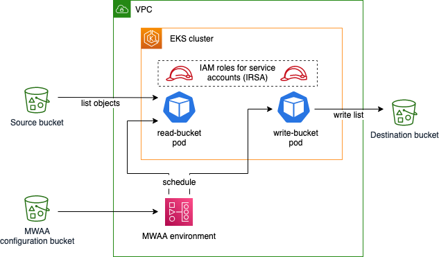
Amazon GTTS works with diverse and distributed data stores, storing petabytes of data. Data engineers need a tool to define ETL jobs which run on various compute environments, as illustrated in the following diagram.

GTTS built Langley as their custom orchestrator in 2018, and have been operating it ever since. At a high level, the core of Langley’s architecture is based on a set of Amazon Simple Queue Service (Amazon SQS) queues and AWS Lambda functions, and a dedicated RDS database to store ETL job data and metadata. It also uses AWS Data Pipeline to run SQL-based workloads, Amazon Simple Storage Service (Amazon S3) to store configuration files, and Amazon CloudWatch for alarming on failures. Every day, Langley handles the lifecycle of more than 17,000 ETL jobs in Europe and 5,000 ETL jobs in North America.
The following diagram illustrates the Langley architecture.

Business challenges
Langley started as a simple solution to a team-internal problem, but its growth over the years surfaced key issues:
- The maintenance of this custom solution requires considerable time from engineers, which increased over the years with the release of new features, increasing the overall complexity.
- The Langley user base grew continuously and eventually became a key orchestration platform for multiple teams and products across Amazon. However, it wasn’t created with multi-tenancy in mind and therefore it didn’t provide the robustness and the appropriate level of isolation to guard each tenant from impacting others on the shared platform.
- In 2023, AWS announced the upcoming deprecation of Data Pipeline, one of the core services used by Langley.
GTTS partnered with AWS to design and implement a solution to overcome those challenges. AWS used the following evaluation matrix to build a durable solution:
| Maintainability | The level of effort required to maintain the orchestrating system in a functional state, encompassing updates, patches, bug fixes, and routine checks for optimal performance. |
| Costs | The overall expenditure associated with the orchestrator, including infrastructure costs, licensing fees, personnel expenses, and other relevant costs. This criterion particularly assesses the system’s ability to effectively control and reduce costs. |
| Scheduling | The capabilities related to running and scheduling jobs, including the ability to resume an ETL job from a failed step. |
| User experience | The overall satisfaction and usability of a system from the end-users’ perspective, considering factors such as responsiveness, accessibility, interoperability, and ease of use. |
| Security | Mechanisms in place to safeguard data and applications from unauthorized access at all times. |
| Monitoring and alerting | The continuous observation and analysis of system components and performance metrics to detect and address issues, optimize resource usage, and provide overall health and reliability. |
| Scalability | The orchestrator’s capacity to efficiently adapt its resources to handle increased workload or demand, providing sustained performance. |
Among the explored solutions, Amazon MWAA was finally determined as the best overall performer across this matrix.
The next section is a dive deep into the rationales that led GTTS and AWS Professional Services to choose Amazon MWAA as the best performer.
Benefits of migrating to Amazon MWAA
Amazon GTTS and AWS Professional Services worked together to release a Minimum Viable Product (MVP) of the solution described earlier, which showcases the benefits on the agreed decision criteria.
Maintainability
With their legacy system, Amazon GTTS had to manage the orchestrator database, web servers, activity queue, dispatch functions, and worker nodes.
Amazon MWAA eliminates the need for underlying infrastructure management. It takes care of provisioning and maintenance of the Apache Airflow web server, scheduler, worker nodes, and relational database, allowing GTTS teams to focus on building their ETL jobs.
Amazon MWAA offers one-click updates of the infrastructure for minor versions, like moving from Airflow version x.4.z to x.5.z. During the upgrade process, Amazon MWAA captures a snapshot of your environment metadata; upgrades the workers, schedulers, and web server to the new Airflow version; and finally restores the metadata database using the snapshot, backing it with an automated rollback mechanism.
Costs
Amazon MWAA contributes to a more cost-effective solution by automatically scaling workers depending on the workload. This dynamic scaling in and out avoids over-provisioning and allows the organization to pay for the compute they actually use, without the risk of downtime during activity spikes. Because this is an AWS-managed solution, it also reduced GTTS’s Total Cost of Ownership (TCO) by freeing up time from engineers that were managing the legacy system.
Scheduling
Amazon MWAA supports all the trigger mechanisms that the Amazon orchestrator needed:
- Manual trigger – The users can simply invoke a Direct Acyclic Graph (DAG) using the Airflow API or even more simply via the User Interface (UI).
- Scheduler – A scheduler can be defined as code, together with the DAG definition, to make sure it will run at specific rates (from hourly to yearly) or on specific cron schedules.
- Event-driven trigger – Airflow provides native operators that enable invoking a downstream DAG from another DAG or from a dataset update (push approach). It also includes sensors that listen for the completion of a task external to the DAG (pull approach).
- Partial runs on DAG failures – Another key feature for GTTS was the possibility the recover from partial DAG failures without having to rerun the whole DAG. Airflow provides task-level controls that makes this operation straightforward to implement.
User experience
In this section, we discuss three aspects of the user experience: the web UI, the interoperability, and the programming interface.
Web UI
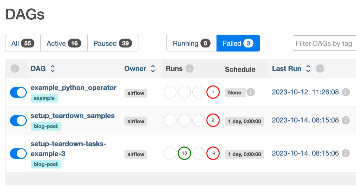
Amazon MWAA comes with a managed web server that hosts the Airflow UI. As a result, and without any maintenance needed, you can use it to quickly run DAGs, check run history, visualize dependencies between DAGs, troubleshoot with a direct access to task logs, manage variables and database connections, and define granular permissions. The following screenshot shows an example of the UI.

Interoperability
One of the most important features evaluated was the ability for the new orchestrator to effortlessly integrate with GTTS multiple data storage services, compute components, and monitoring services.
Amazon MWAA comes with a wide variety of providers preinstalled, such as apache-airflow-providers-amazon, apache-airflow-providers-postgres, and apache-airflow-providers-common-sql. This allowed GTTS to connect with those services using multiple connection methodologies, including AWS IAM Identity Center or AWS Secrets Manager password-based authentications, without having to write a single custom Airflow operator.
Amazon MWAA also makes it straightforward to upgrade providers version and install new ones. By providing a requirements.txt file, GTTS was able to change the major version of apache-airflow-providers-amazon and install the apache-airflow-providers-mysql provider.
Programming interface
Airflow is an orchestrator with a low barrier to entry, especially for those familiar with the Python programming language. Its workflow management is defined in Python scripts, with a well-documented set of native operators and external providers, making it straightforward for Python developers to get started with Airflow and create complex data pipelines.
The following are two key Airflow features:
- TaskFlow API – The TaskFlow API removes a lot of the boilerplate code required by traditional operators by using Python decorators while simplifying the DAG editing process DAG with cleaner and more concise DAG files.
- Dynamic DAG generation – The dynamic DAG generation capability allowed us to generate DAGs from the original legacy orchestrator’s configuration files. This enabled the platform team to build a centralized framework consumed by multiple teams to keep the code DRY (Don’t Repeat Yourself), providing a seamless migration journey from the legacy orchestrator.
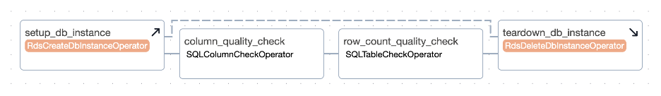
The following screenshot shows an example of these features.

Security
The new Amazon MWAA-based architecture improves GTTS’s posture by introducing granular access control. Amazon MWAA integrates with AWS services such as AWS Key Management Service (AWS KMS), Secrets Manager, and IAM Identity Center to keep data safely encrypted at all times, both at rest and in transit using TLS-based communications. Airflow also includes a role-based access control (RBAC) model to determine what users can do on the platform and enforce the principle of least privilege. Amazon MWAA also natively integrates with AWS CloudTrail for auditing purposes.
The Airflow RBAC model enables administrators to define roles with specific privileges to access Airflow system settings and DAGs themselves. This granular access control reduces the risk of data breaches and malicious activities by limiting access to critical DAGs and sensitive Airflow environment variables. Airflow includes five default roles with different sets of permissions (as shown in the following screenshot), but it is possible to create new roles depending on your security requirements.

GTTS used the Airflow RBAC model to restrict permissions of certain teams and consumers of the application. They also used priority weights and Airflow pools to prioritize tasks and control run concurrency. However, if you want to run a multi-tenant orchestration platform, it’s recommended to use a separate environment for each team. You can assume that everything accessible by the Amazon MWAA role is also accessible to users who can write DAGs to the environment.
To ease authentication in Amazon MWAA, GTTS federated their identity provider (IdP) through Amazon Cognito and SAML. With this integration, users log in to the Amazon MWAA UI using the same identity as in other internal systems, which removes the need for new credentials. The user’s group membership is retrieved from the IdP through Amazon Cognito, and a Lambda function redirects the user to Amazon MWAA with the appropriate Airflow role. This process is illustrated in the following architecture, and is abstracted from the user and attached to a public Application Load Balancer that redirects at the end of the process to an Amazon MWAA private cluster, making the authentication workflow seamless and secure. Refer to Accessing a private Amazon MWAA environment using federated identities to implement it using your own IdP.

Monitoring and alerting
Amazon MWAA integrates with CloudWatch, which manages all infrastructure logs for you. When creating an Amazon MWAA environment, you can configure what level of logs should be saved. GTTS enabled CloudWatch logging for all of the five types of components: Airflow task logs, Airflow web server logs, Airflow scheduler logs, Airflow worker logs, and Airflow DAG processing logs.

These logs are all accessible in CloudWatch for continuous monitoring, but Amazon MWAA users can also access task logs directly from the Airflow UI by looking at the DAG run history. The following screenshot shows an example of task-level logs in Airflow 2.5.1.

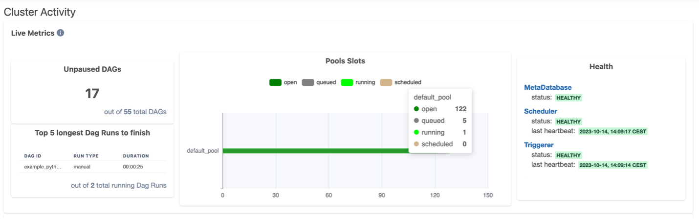
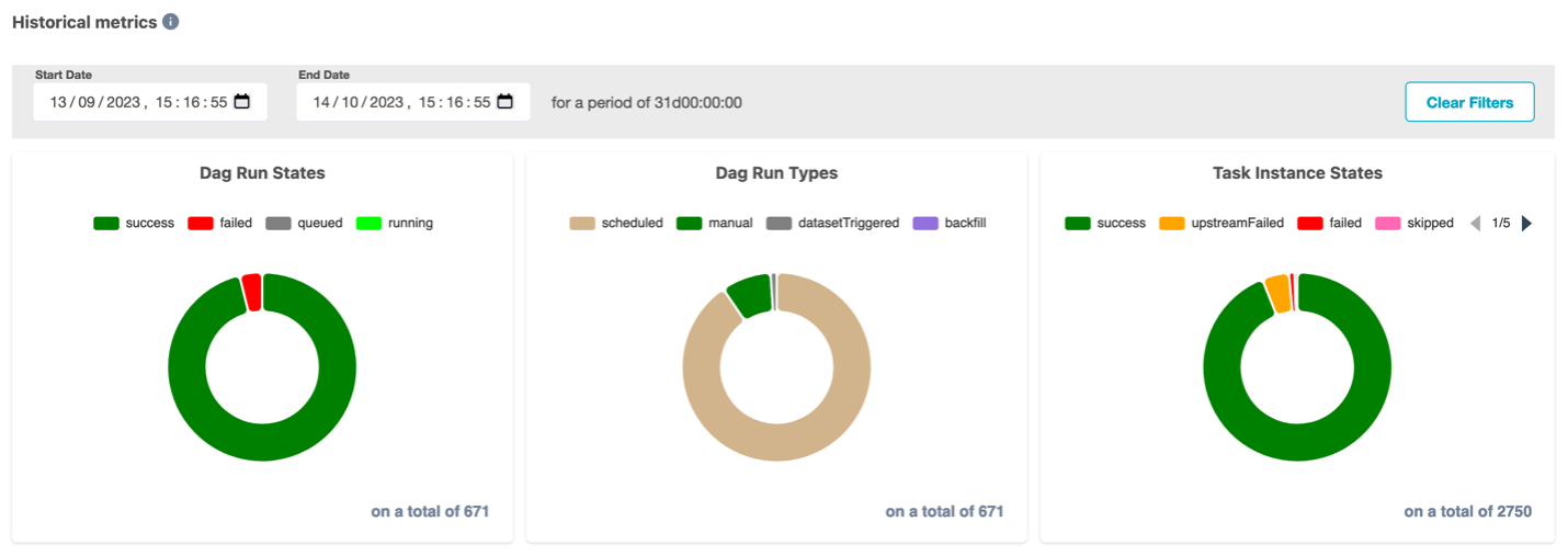
You can also build CloudWatch monitoring dashboards to keep an eye on the state of your environment and alert administrators when required. Amazon MWAA natively provides Airflow environment metrics and Amazon MWAA infrastructure-related metrics.
Scalability
Each Amazon MWAA environment includes the schedulers, web server, and worker nodes. Scheduler nodes are responsible for the overall orchestration and parsing of DAG files. These tasks happen in worker nodes that Amazon MWAA auto scales up and down according to system load. When creating a new Amazon MWAA environment, you need to specify the type of worker nodes, the minimum and maximum number of worker nodes, and the scheduler count, as shown in the following screenshot.

There are notably two ways GTTS controlled how Amazon MWAA scales to handle the load:
- Minimum and maximum worker count – Amazon MWAA automatically adds or deletes workers within the boundaries you set, depending on the number of tasks that are waiting to be processed. As indicated in the AWS documentation, it is possible to request a quota increase to run up to 50 workers in a single environment.
- Size of the node – Larger worker nodes can run more concurrent tasks. For example, mw1.small instances run 5 concurrent tasks by default, whereas mw1.large instances run 20 concurrent tasks by default. The following figure shows the specification for each instance type.

With Amazon MWAA, GTTS can therefore run up to 4,000 concurrent tasks in a single Amazon MWAA environment (50 worker nodes x 80 tasks per node with mw1.2xlarge). This remains an order of magnitude for the load that can fit into the workers vCPUs and RAM, but it is possible to edit the default configuration to add even more tasks per worker. For more information regarding Amazon MWAA automatic scaling, see Configuring Amazon MWAA automatic scaling.
The Amazon MWAA based orchestration platform
After selecting Amazon MWAA as the core service for their orchestrating system, Amazon GTTS and AWS worked together to develop an end-to-end data platform with automation capabilities, access management, monitoring, and integration with downstream systems. The following diagram illustrates the solution architecture.

The following are notable components of the architecture:
- DAG update – GTTS Developers manage the creation, update, and deletion of Amazon MWAA DAGs through a dedicated code repository. When a developer edits DAG definitions and commits changes to the code repository, a CI/CD pipeline automatically packages the DAG definition and stores it in Amazon S3, which automatically updates DAGs in Amazon MWAA.
- Infrastructure as code – The entire stack is defined as IaC with the AWS CDK, which eases the process of updating components, and makes it repeatable if GTTS wants to extend the solution and redeploy the stack in multiple AWS Regions.
- Authentication, authorizations, and Permissions – Permissions are centrally managed with AWS Identity and Access Management (IAM) together with Airflow roles. GTTS integrated their identity provider with Amazon Cognito and Amazon MWAA, so Amazon employees can connect to the Amazon MWAA UI with the same authentication tool they are used to, and see only the DAGs they are allowed to access.
- UI and DAG runs – Amazon MWAA includes an AWS-managed web server that exposes the Airflow UI. Amazon employees can connect to this UI to list DAGs, run DAGs, and track their status. In addition, GTTS used the native Amazon MWAA scheduler to automatically invoke DAGs at a specific time.
- Airflow workers – The users can use Airflow native providers to run custom Shell or Python code directly on the workers nodes. For compute-intensive jobs, the Amazon MWAA worker can delegate the compute to a more suitable AWS service, such as Apache Spark running on Amazon EMR on Amazon EKS, which will provide compute resources only for the duration of the job, helping in optimizing costs.
- Data stores and external computes services – Amazon MWAA comes also with the AWS provider preloaded, allowing a seamless connectivity with more than 23 AWS compute and data services. GTTS can extend the connectivity to other AWS or external services by using Boto3 with the
PythonOperatoror creating dedicated custom operators. - Logging and alerting – Amazon MWAA is seamlessly integrated with CloudWatch and CloudTrail to publish DAG logs, audit logs, and metrics. This enables GTTS to track completion, troubleshoot, and create an automated alerting and notifications system so DAGs owners can take remediation actions as fast as possible.
Conclusion
Amazon GTTS partnered with AWS Professional Services to overcome the challenges faced by their legacy custom orchestrator against various dimensions such as maintainability, cost efficiency, security, scalability, and observability.
The new Amazon MWAA-based architecture offers significant improvements in the context of the AWS Well-Architected Framework compared to their former system. In terms of operational excellence, the new orchestration platform is built with evolutivity in mind and enables the GTTS team to use the most adapted ETL service to run their jobs. Regarding performance efficiency, GTTS observed up to 70% improvement in end-to-end runtime on their jobs running in Amazon MWAA. In terms of security, the new solution implements best practices such as the deployment in private subnets, authentication of users through Amazon internal federation systems, and data encryption at rest and in transit. Reliability is achieved with Multi-AZ failover and built-in auto scaling to meet the workload demand at all times. Finally, cost is reduced because Amazon MWAA is an AWS-managed service, which decreases the human effort from GTTS to maintain the orchestration platform.
Amazon GTTS is now bringing the MVP into production, where it is planned to handle petabytes of data and host more than 2,000 jobs migrated from the legacy system. Additionally, the migration to Amazon MWAA has empowered GTTS to enhance its operational scalability, paving the way for the integration of new jobs and further expansion with greater efficiency and confidence.
To learn more, refer to the following resources:
- Get started with Amazon Managed Workflows for Apache Airflow
- Amazon MWAA blog posts
- Amazon MWAA for Analytics Workshop
- Amazon Managed Workflows for Apache Airflow at Scale
About the Authors
Béntor Bautista is a Senior Data Engineer at Amazon GTTS
Louis Hourcade is a Solutions Architect at AWS
Raphael Ducay is a Senior DataOps Architect at AWS
Konstantin Zarudaev is a DevOps Consultant at AWS
Dorra Elboukari is a DevOps Architect at AWS
Marcin Zapal is an Engagement Manager at AWS
Grigorios Pikoulas is a Strategic Program Lead at AWS
Antonio Cennamo is a Senior Customer Practice Manager at AWS


 Satya Chikkala is a Solutions Architect at Amazon Web Services. Based in Melbourne, Australia, he works closely with enterprise customers to accelerate their cloud journey. Beyond work, he is very passionate about nature and photography.
 Vijay Velpula is a Data Lake Architect with AWS Professional Services. He assists customers in building modern data platforms by implementing big data and analytics solutions. Outside of his professional responsibilities, Velpula enjoys spending quality time with his family, as well as indulging in travel, hiking, and biking activities.


 Noritaka Sekiyama is a Principal Big Data Architect on the AWS Glue team and AWS Data Pipeline team. He is responsible for building software artifacts to help customers. In his spare time, he enjoys cycling with his road bike.
 Vaibhav Porwal is a Senior Software Development Engineer on the AWS Glue and AWS Data Pipeline team. He is working on solving problems in orchestration space by building low cost, repeatable, scalable workflow systems that enables customers to create their ETL pipelines seamlessly.
 Sriram Ramarathnam is a Software Development Manager on the AWS Glue and AWS Data Pipeline team. His team works on solving challenging distributed systems problems for data integration across AWS serverless and serverfull compute offerings.
 Matt Su is a Senior Product Manager on the AWS Glue team and AWS Data Pipeline team. He enjoys helping customers uncover insights and make better decisions using their data with AWS Analytics services. In his spare time, he enjoys skiing and gardening.


 Hernan Garcia is a Senior Solutions Architect at AWS, based out of Amsterdam, working with enterprises in the Financial Services Industry. He specializes in application modernization and supports customers in the adoption of serverless technologies.
 Parnab Basak is a Solutions Architect and a Serverless Specialist at AWS. He specializes in creating new solutions that are cloud native using modern software development practices like serverless, DevOps, and analytics. Parnab works closely in the analytics and integration services space helping customers adopt AWS services for their workflow orchestration needs.


 Matthias Rudolph is an Associate Solutions Architect, digitalizing the German manufacturing industry.
 Stephen Said is a Senior Solutions Architect and works with Retail/CPG customers. His areas of interest are data platforms and cloud-native software engineering.


 Chandan Rupakheti is a Senior Solutions Architect at AWS. His main focus at AWS lies in the intersection of Analytics, Serverless, and AdTech services. He is a passionate technical leader, researcher, and mentor with a knack for building innovative solutions in the cloud. Outside of his professional life, he loves spending time with his family and friends besides listening and playing music.
 Parnab Basak is a Senior Solutions Architect and a Serverless Specialist at AWS. He specializes in creating new solutions that are cloud native using modern software development practices like serverless, DevOps, and analytics. Parnab works closely in the analytics and integration services space helping customers adopt AWS services for their workflow orchestration needs.


 Mansi Bhutada is an ISV Solutions Architect based in the Netherlands. She helps customers design and implement well-architected solutions in AWS that address their business problems. She is passionate about data analytics and networking. Beyond work, she enjoys experimenting with food, playing pickleball, and diving into fun board games.
 Kartikay Khator is a Solutions Architect within the Global Life Sciences at AWS, where he dedicates his efforts to developing innovative and scalable solutions that cater to the evolving needs of customers. His expertise lies in harnessing the capabilities of AWS Analytics services. Extending beyond his professional pursuits, he finds joy and fulfillment in the world of running and hiking. Having already completed two marathons, he is currently preparing for his next marathon challenge.
 Kamen Sharlandjiev is a Sr. Big Data and ETL Solutions Architect, MWAA and AWS Glue ETL expert. He’s on a mission to make life easier for customers who are facing complex data integration and orchestration challenges. His secret weapon? Fully managed AWS services that can get the job done with minimal effort. Follow Kamen on


 Sidhanth Muralidhar is a Principal Technical Account Manager at AWS. He works with large enterprise customers who run their workloads on AWS. He is passionate about working with customers and helping them architect workloads for costs, reliability, performance, and operational excellence at scale in their cloud journey. He has a keen interest in data analytics as well.


 Jayesh Shinde is Sr. Application Architect with AWS ProServe India. He specializes in creating various solutions that are cloud centered using modern software development practices like serverless, DevOps, and analytics.
 Harshd Yeola is Sr. Cloud Architect with AWS ProServe India helping customers to migrate and modernize their infrastructure into AWS. He specializes in building DevSecOps and scalable infrastructure using containers, AIOPs, and AWS Developer Tools and services.


 Hernan Garcia is a Senior Solutions Architect at AWS based in the Netherlands. He works in the financial services industry, supporting enterprises in their cloud adoption. He is passionate about serverless technologies, security, and compliance. He enjoys spending time with family and friends, and trying out new dishes from different cuisines.
 Jeetendra Vaidya is a Senior Solutions Architect at AWS, bringing his expertise to the realms of AI/ML, serverless, and data analytics domains. He is passionate about assisting customers in architecting secure, scalable, reliable, and cost-effective solutions.
 Sriharsh Adari is a Senior Solutions Architect at AWS, where he helps customers work backward from business outcomes to develop innovative solutions on AWS. Over the years, he has helped multiple customers on data platform transformations across industry verticals. His core area of expertise includes technology strategy, data analytics, and data science. In his spare time, he enjoys playing sports, watching TV shows, and playing Tabla.


 Mansi Bhutada is an ISV Solutions Architect based in the Netherlands. She helps customers design and implement well-architected solutions in AWS that address their business problems. She is passionate about data analytics and networking. Beyond work, she enjoys experimenting with food, playing pickleball, and diving into fun board games.


 Chandan Rupakheti is a Solutions Architect and a Serverless Specialist at AWS. He is a passionate technical leader, researcher, and mentor with a knack for building innovative solutions in the cloud and bringing stakeholders together in their cloud journey. Outside his professional life, he loves spending time with his family and friends besides listening and playing music.
 Vinod Jayendra is a Enterprise Support Lead in ISV accounts at Amazon Web Services, where he helps customers in solving their architectural, operational, and cost optimization challenges. With a particular focus on Serverless technologies, he draws from his extensive background in application development to deliver top-tier solutions. Beyond work, he finds joy in quality family time, embarking on biking adventures, and coaching youth sports team.
 Rupesh Tiwari is a Senior Solutions Architect at AWS in New York City, with a focus on Financial Services. He has over 18 years of IT experience in the finance, insurance, and education domains, and specializes in architecting large-scale applications and cloud-native big data workloads. In his spare time, Rupesh enjoys singing karaoke, watching comedy TV series, and creating joyful moments with his family.


 Rahul Sonawane is a Principal Analytics Solutions Architect at AWS with AI/ML and Analytics as his area of specialty.
 Gaurav Parekh is a Solutions Architect helping AWS customers build large scale modern architecture. He specializes in data analytics and networking. Outside of work, Gaurav enjoys playing cricket, soccer and volleyball.
 John Jackson has over 25 years of software experience as a developer, systems architect, and product manager in both startups and large corporations and is the AWS Principal Product Manager responsible for Amazon MWAA.
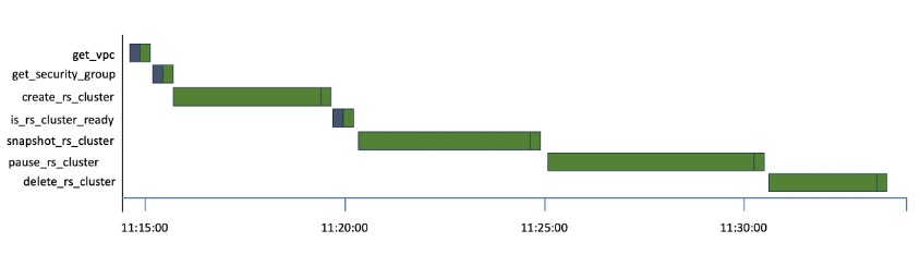

 Manasi Bhutada is an ISV Solutions Architect based in the Netherlands. She helps customers design and implement well architected solutions in AWS that address their business problems. She is passionate about data analytics and networking. Beyond work she enjoys experimenting with food, playing pickleball, and diving into fun board games.


 Ulrich Hinze is a Solutions Architect at AWS. He partners with software companies to architect and implement cloud-based solutions on AWS. Before joining AWS, he worked for AWS customers and partners in software engineering, consulting, and architecture roles for 8+ years.
 Patrick Oberherr is a Staff Data Engineer at Contentful with 4+ years of working with AWS and 10+ years in the Data field. At Contentful he is responsible for infrastructure and operations of the data stack which is hosted on AWS.
 Johannes Günther is a cloud & data consultant at Netlight with 5+ years of working with AWS. He has helped clients across various industries designing sustainable cloud platforms and is AWS certified.
 AWS Global Summits – The 2023 AWS Summits season is almost coming to an end with the last two in-person events in