Tag Archives: Architecture

Let’s Architect! Architecting for governance and management

Post Syndicated from Luca Mezzalira original https://aws.amazon.com/blogs/architecture/lets-architect-architecting-for-governance-and-management/

As you develop next-generation cloud-native applications and modernize existing workloads by migrating to cloud, you need cloud teams that can govern centrally with policies for security, compliance, operations and spend management.

In this edition of Let’s Architect!, we gather content to help software architects and tech leaders explore new ideas, case studies, and technical approaches to help you support production implementations for large-scale migrations.

Seamless Transition from an AWS Landing Zone to AWS Control Tower

A multi-account AWS environment helps businesses migrate, modernize, and innovate faster. With the large number of design choices, setting up a multi-account strategy can take a significant amount of time, because it involves configuring multiple accounts and services and requires a deep understanding of AWS.

This blog post shows you how AWS Control Tower helps customers achieve their desired business outcomes by setting up a scalable, secure, and governed multi-account environment. This post describes a strategic migration of 140 AWS accounts from customer Landing Zone to an AWS Control Tower-based solution.

Multi-account landing zone architecture that uses AWS Control Tower

Multi-account landing zone architecture that uses AWS Control Tower

Build a strong identity foundation that uses your existing on-premises Active Directory

How do you use your existing Microsoft Active Directory (AD) to reliably authenticate access for AWS accounts, infrastructure running on AWS, and third-party applications?

The architecture shown in this blog post is designed to be highly available and extends access to your existing AD to AWS, which enables your users to use their existing credentials to access authorized AWS resources and applications. This post highlights the importance of implementing a cloud authentication and authorization architecture that addresses the variety of requirements for an organization’s AWS Cloud environment.

Multi-account Complete AD architecture with trusts and AWS SSO using AD as the identity source

Multi-account Complete AD architecture with trusts and AWS SSO using AD as the identity source

Migrate Resources Between AWS Accounts

AWS customers often start their cloud journey with one AWS account, and over time they deploy many resources within that account. Eventually though, they’ll need to use more accounts and migrate resources across AWS Regions and accounts to reduce latency or increase resiliency.

This blog post shows four approaches to migrate resources based on type, configuration, and workload needs across AWS accounts.

Migration infrastructure approach

Migration infrastructure approach

Transform your organization’s culture with a Cloud Center of Excellence

As enterprises seek digital transformation, their efforts to use cloud technology within their organizations can be a bit disjointed. This video introduces you to the Cloud Center of Excellence (CCoE) and shows you how it can help transform your business via cloud adoption, migration, and operations. By using the CCoE, you’ll establish and us a cross-functional team of people  for developing and managing your cloud strategy, governance, and best practices that your organization can use to transform the business using the cloud.

Benefits of CCoE

Benefits of CCoE

See you next time!

Thanks for reading! If you want to dive into this topic even more, don’t miss the Management and Governance on AWS product page.

See you in a couple of weeks with novel ways to architect for front-end web and mobile!

Other posts in this series

Looking for more architecture content?

AWS Architecture Center provides reference architecture diagrams, vetted architecture solutions, Well-Architected best practices, patterns, icons, and more!

Monitoring and alerting break-glass access in an AWS Organization

Post Syndicated from Haresh Nandwani original https://aws.amazon.com/blogs/architecture/monitoring-and-alerting-break-glass-access-in-an-aws-organization/

Organizations building enterprise-scale systems require the setup of a secure and governed landing zone to deploy and operate their systems. A landing zone is a starting point from which your organization can quickly launch and deploy workloads and applications with confidence in your security and infrastructure environment as described in What is a landing zone?. Nationwide Building Society (Nationwide) is the world’s largest building society. It is owned by its 16 million members and exists to serve their needs. The Society is one of the UK’s largest providers for mortgages, savings and current accounts, as well as being a major provider of ISAs, credit cards, personal loans, insurance, and investments.

For one of its business initiatives, Nationwide utilizes AWS Control Tower to build and operate their landing zone which provides a well-established pattern to set up and govern a secure, multi-account AWS environment. Nationwide operates in a highly regulated industry and our governance assurance requires adequate control of any privileged access to production line-of-business data or to resources which have access to them. We chose for this specific business initiative to deploy our landing zone using AWS Organizations, to benefit from ongoing account management and governance as aligned with AWS implementation best practices. We also utilized AWS Single Sign-On (AWS SSO) to create our workforce identities in AWS once and manage access centrally across our AWS Organization. In this blog, we describe the integrations required across AWS Control Tower and AWS SSO to implement a break-glass mechanism that makes access reporting publishable to system operators as well as to internal audit systems and processes. We will outline how we used AWS SSO for our setup as well as the three architecture options we considered, and why we went with the chosen solution.

Sourcing AWS SSO access data for near real-time monitoring

In our setup, we have multiple AWS Accounts and multiple trails on each of these accounts. Users will regularly navigate across multiple accounts as they operate our infrastructure, and their journeys are marked across these multiple trails. Typically, AWS CloudTrail would be our chosen resource to clearly and unambiguously identify account or data access.  The key challenge in this scenario was to design an efficient and cost-effective solution to scan these trails to help identify and report on break-glass user access to account and production data. To address this challenge, we developed the following two architecture design options.

Option 1: A decentralized approach that uses AWS CloudFormation StackSets, Amazon EventBridge and AWS Lambda

Our solution entailed a decentralized approach by deploying a CloudFormation StackSet to create, update, or delete stacks across multiple accounts and AWS Regions with a single operation. The Stackset created Amazon EventBridge rules and target AWS Lambda functions. These functions post to EventBridge in our audit account. Our audit account has a set of Lambda functions running off EventBridge to initiate specific events, format the event message and post to Slack, our centralized communication platform for this implementation. Figure 1 depicts the overall architecture for this option.

De-centralized logging using Amazon EventBridge and AWS Lambda

Figure 1. De-centralized logging using Amazon EventBridge and AWS Lambda

Option 2: Use an organization trail in the Organization Management account

This option uses the centralized organization trail in the Organization Management account to source audit data. Details of how to create an organization trail can be found in the AWS CloudTrail User Guide. CloudTrail was configured to send log events to CloudWatch Logs. These events are then sent via Lambda functions to Slack using webhooks. We used a public terraform module in this GitHub repository to build this Lambda Slack integration. Figure 2 depicts the overall architecture for this option.

Centralized logging pattern using Amazon CloudWatch

Figure 2. Centralized logging pattern using Amazon CloudWatch

This was our preferred option and is the one we finally implemented.

We also evaluated a third option which was to use centralized logging and auditing feature enabled by Control Tower. Users authenticate and federate to target accounts from a central location so it seemed possible to source this info from the centralized logs. These log events arrive as .gz compressed json objects, which meant having to expand these archives repeatedly for inspection. We therefore decided against this option.

A centralized, economic, extensible solution to alert of SSO break-glass

Our requirement was to identify break-glass access across any of the access mechanisms supported by AWS, including CLI and User Portal access. To ensure we have comprehensive coverage across all access mechanisms, we identified all the events initiated for each access mechanism:

  1. User Portal/AWS Console access events
    • Authenticate
    • ListApplications
    • ListApplicationProfiles
    • Federate – this event contains the role that the user is federating into
  2. CLI access events
    • CreateToken
    • ListAccounts
    • ListAccountRoles
    • GetRoleCredentials – this event contains the role that the user is federating into

EventBridge is able to initiate actions after events only when the event is trying to perform changes (when the “readOnly” attribute on the event record body equals “false”).

The AWS support team was aware of this attribute and recommended that we, change the data flow we were using to one able to initiate actions after any kind of event, regardless of the value on its readOnly attribute. The solution in our case was to send the CloudTrail logs to CloudWatch Logs. This then and initiates the Lambda function through a filter subscription that detects the desired event names on the log content.

The filter used is as follows:

{($.eventSource = sso.amazonaws.com) && ($.eventName = Federate||$.eventName = GetRoleCredentials)}

Due to the query size in the CloudWatch Log queries we had to remove the subscription filters and do the parsing of the content of the log lines inside the lambda function. In order to determine what accounts would initiate the notifications, we sent the list of accounts and roles to it as an environment variable at runtime.

Considerations with cross-account SSO access

With direct federation users get an access token. This is most obvious in AWS single sign on at the chiclet page as “Command line or programmatic access”. SSO tokens have a limited lifetime (we use the default 1-hour). A user does not have to get a new token to access a target resource until the one they are using is expired. This means that a user may repeatedly access a target account using the same token during its lifetime. Although the token is made available at the chiclet page, the GetRoleCredentials event does not occur until it is used to authenticate an API call to the target AWS account.

Conclusion

In this blog, we discussed how AWS Control Tower and AWS Single Sign-on enabled Nationwide to build and govern a secure, multi-account AWS environment for one of their business initiatives and centralize access management across our implementation. The integration was important for us to accurately and comprehensively identify and audit break-glass access for our implementation. As a result, we were able to satisfy our security and compliance audit requirements for privileged access to our AWS accounts.

Implementing lightweight on-premises API connectivity using inverting traffic proxy

Post Syndicated from Oleksiy Volkov original https://aws.amazon.com/blogs/architecture/implementing-lightweight-on-premises-api-connectivity-using-inverting-traffic-proxy/

This post will explore the use of lightweight application inversion proxy as a solution for multi-point hybrid or multi-cloud, API-level connectivity for cases where AWS Direct Connect or VPN may not be practical. Then, we will present a sample solution and explain how it addresses typical challenges involved in this space.

Defining the issue

Large ISV providers and integration vendors often need to have API-level integration between a central cloud-based system and a number of on-premises APIs. Use cases can range from refactoring/modernization initiatives to interfacing with legacy on-premises applications, which have no direct migration path to the cloud.

The typical approach is to use VPN or Direct Connect, as they can provide significant benefits in terms of latency and security. However, they are not always practical in situations involving multi-source systems deployed by various groups or organizations that may have significant budget, process, or timeline constraints.

Conceptual solution

An option that addresses the connectivity need is an inverting application proxy, which can be deployed as a lightweight executable on an on-premises backend. The locally deployed agent can communicate with the proxy server on AWS using an inverted communication pattern. This means that the agent will establish outbound connection to the proxy, and it will use the connection to receive inbound requests, too. Figure 1 describes a sample architecture using inverting proxy pattern using Amazon API Gateway façade.

Inverting application proxy

Figure 1. Inverting application proxy

The advantages of this approach include ease-of-deployment (drop-in executable agent) and -configuration. As the proxy inverts the direction of application connectivity to originate from on-premises servers, the local firewall does not need to be reconfigured to open additional ports needed for traditional proxy deployment.

Realizing the solution on AWS

We have built a sample traffic routing solution based on the original open-source Inverting Proxy and Agent by Ian Maddox, Jason Cooke, and Omar Janjur. The solution is written in Go and leverages multiple AWS services to provide additional telemetry, security, and discoverability capabilities that address the common needs of enterprise customers.

The solution is comprised of an inverting proxy and a forwarding agent. The inverting proxy is deployed on AWS as a stand-alone executable running on Amazon Elastic Compute Cloud (EC2) and responsible for forwarding traffic to the agent. The agent can be deployed as a binary or container within the target on-premises system.

Upon starting, the agent will establish an outbound connection with the proxy and local sever application. Once established, the proxy will use it in reverse to forward all incoming client requests through the agent and to the backend application. The connection is secured by Transport Layer Security (TLS) to protect communications between client and proxy and between agent and backend application.

This solution uses a unique backend ID and IAM user/role tags to identify different backend servers and control access to proxies. The backend ID is passed as a command-line parameter to the agent. The agent checks the IAM account or IAM role Amazon EC2 is running under for tag “AllowedBackends”. The tag contains coma-separated list of backend IDs that the agent is allowed to access. The connectivity is established only if the provided backend ID matches one of the values in the coma-separated list.

The solution supports native integration with AWS Cloud Map to enable automatic discoverability of remote API endpoints. Upon start and once the IAM access control checks are successfully validated, the agent can register the backend endpoints within AWS Cloud Map using a provided service name and service namespace ID.

Inverting proxy agent can collect telemetry and automatically publish it to Amazon CloudWatch using a custom namespace. This includes HTTP response codes and counts from server application aggregated by the backend ID.

For full list of options, features, and supported configurations, use --help command-line parameter with both agent and proxy executables.

Enabling highly resilient proxy deployment

For production scenarios that require high availability, deploy a pair of inverting proxies connecting to a pair of agents deployed on separate EC2 instances. The entire configuration is then placed behind Application Load Balancer to provide a single point of ingress, load-balancing, and health-checking functionality. Figure 2 demonstrates a highly resilient setup for critical workloads.

Highly resilient deployment diagram for inverting proxy

Figure 2. Highly resilient deployment diagram for inverting proxy

Additionally, for real-life production workloads dealing with sensitive data, we recommend following security and resilience best practices for Amazon EC2.

Deploying and running the solution

The solution includes a simple demo Node.js server application to simulate connectivity with an inverting proxy. A restrictive security group will be used to simulate on-premises data center.

Steps to deployment:

1. Create a “backend” Amazon EC2 server using Linux 2, free-tier AMI. Ensure that Port 443 (inbound port for sample server application) is blocked from external access via appropriate security group.

2. Connect by using SSH into target server run updates.

sudo yum update -y

3. Install development tools and dependencies:

sudo yum groupinstall "Development Tools" -y

4. Install Golang:

sudo yum install golang -y

5. Install node.js.

curl -o- https://raw.githubusercontent.com/nvm-sh/nvm/v0.34.0/install.sh | bash

. ~/.nvm/nvm.sh

nvm install 16

6. Clone the inverting proxy GitHub repository to the “backend” EC2 instance.

7. From inverting-proxy folder, build the application by running:

mkdir /home/ec2-user/inverting-proxy/bin

export GOPATH=/home/ec2-user/inverting-proxy/bin

make

8. From /simple-server folder, run the sample appTLS application in the background (see instructions below). Note: to enable SSL you will need to generate encryption key and certificate files (server.crt and server.key) and place them in simple-server folder.

npm install

node appTLS &

Example app listening at https://localhost:443

Confirm that the application is running by using ps -ef | grep node:

ec2-user  1700 30669  0 19:45 pts/0    00:00:00 node appTLS

ec2-user  1708 30669  0 19:45 pts/0    00:00:00 grep --color=auto node

9. For backend Amazon EC2 server, navigate to Amazon EC2 security settings and create an IAM role for the instance. Keep default permissions and add “AllowedBackends” tag with the backend ID as a tag value (the backend ID can be any string that matches the backend ID parameter in Step 13).

10. Create a proxy Amazon EC2 server using Linux AMI in a public subnet and connect by using SSH in an Amazon EC2 once online. Copy the contents of the bin folder from the agent EC2 or clone the repository and follow build instructions above (Steps 2-7).

Note: the agent will be establishing outbound connectivity to the proxy; open the appropriate port (443) in the proxy Amazon EC2 security group. The proxy server needs to be accessible by the backend Amazon EC2 and your client workstation, as you will use your local browser to test the application.

11. To enable TLS encryption on incoming connections to proxy, you will need to generate and upload the certificate and private key (server.crt and server.key) to the bin folder of the proxy deployment.

12. Navigate to /bin folder of the inverting proxy and start the proxy by running:

sudo ./proxy –port 443 -tls

2021/12/19 19:56:46 Listening on [::]:443

13. Use the SSH to connect into the backend Amazon EC2 server and configure the inverting proxy agent. Navigate to /bin folder in the cloned repository and run the command below, replacing uppercase strings with the appropriate values. Note: the required trailing slash after the proxy DNS URL.

./proxy-forwarding-agent -proxy https://YOUR_PROXYSERVER_PUBLIC_DNS/ -backend SampleBackend-host localhost:443 -scheme https

14. Use your local browser to navigate to proxy server public DNS name (https://YOUR_PROXYSERVER_PUBLIC_DNS). You should see the following response from your sample backend application:

Hello World!

Conclusion

Inverting proxy is a flexible, lightweight pattern that can be used for routing API traffic in non-trivial hybrid and multi-cloud scenarios that do not require low-latency connectivity. It can also be used for securing existing endpoints, refactoring legacy applications, and enabling visibility into legacy backends. The sample solution we have detailed can be customized to create unique implementations and provides out-of-the-box baseline integration with multiple AWS services.

Let’s Architect! Creating resilient architecture

Post Syndicated from Luca Mezzalira original https://aws.amazon.com/blogs/architecture/lets-architect-creating-resilient-architecture/

The AWS Well-Architected Framework defines resilience as “the capability to recover when stressed by load (more requests for service), attacks (either accidental through a bug, or deliberate through intention), and failure of any component in the workload’s components.”

The need for resilient workloads transcends all customer industries, but it can often can be misunderstood, which can lead to workloads that do not incorporate resilient architecture at all or workloads that are over-engineered.

Resilience is a technical problem, but it’s also about people and culture. It’s a continuous process that requires us to learn by iterating. Customers need to understand, from a business perspective, what their SLA requirements are, and from technical perspective, how they achieve this with their architecture. In this post, we share resources to help you build resilience into your AWS architecture.

Amazon’s approach to building resilient services

Building a resilient architecture is not only about the technical implementation of the system, but also about the solutions for observability, operations, and people.

This video shows the Amazon approach for designing resilient systems, where individual teams build and own a service. This way, everyone has operational responsibility. You’ll learn how to deploy often, move fast, and design solutions for automatic rollback, which allows teams to revert their workload to a previous iteration if needed.

The pillars adopted by the engineering teams building services at Amazon

The pillars adopted by the engineering teams building services at Amazon

Five design patterns to build more resilient applications

Resilience is an important consideration for developers. For instance, if a downstream service is not available, how can the software handle the situation? Which mechanisms should you use to implement retries? How can you prevent overloading the downstream service?

This video focuses on five strategies and design patterns that developers can use to build resilient applications. You’ll learn how to add timeouts, retries, exponential backoff with randomness, and circuit breakers into your code. These patterns are powerful because they can be abstracted and implemented in different scenarios.

Software developers can implement different strategies in their application code to design for resiliency

Software developers can implement different strategies in their application code to design for resiliency

Building Resilient Well-Architected Workloads Using AWS Resilience Hub

This blog post shows you how AWS Resilience Hub can help you evaluate the resilience of your architecture. It gives you a central place to monitor, track, and evaluate your application’s resiliency based on your business goals. For example, after you define your RPO and RTO SLAs, Resilience Hub will evaluate your current architecture against them and show you whether you’ve met your goals. If you haven’t met your goals, it recommends changes to help you meet them.

Multi-AZ architecture incorporating data backup features

Multi-AZ architecture incorporating data backup features

Incorporating continuous resilience in your development ecosystem

Resilience encompasses a broad range of considerations, including infrastructure, application patterns, data management, and application building and monitoring. And after you incorporate resilience, it is essential to continuously maintain it.

This video provides useful principles for building continuous resilience in your applications. It also explores various considerations for implementing processes designed to provide continuous improvement through a DevOps methodology and shows you services you can use to incorporate resilience in the development process in a nearly continuous manner.

Software architects can implement several patterns to prevent failures or being fault-tolerant

Software architects can implement several patterns to prevent failures or being fault-tolerant

See you next time!

Thanks for joining our discussion on resilient architecture! See you in a couple of weeks with our content about governance in the cloud!

Looking for more architecture content? AWS Architecture Center provides reference architecture diagrams, vetted architecture solutions, Well-Architected best practices, patterns, icons, and more!

Other posts in this series


Modernization pathways for a legacy .NET Framework monolithic application on AWS

Post Syndicated from Ramakant Joshi original https://aws.amazon.com/blogs/architecture/modernization-pathways-for-a-legacy-net-framework-monolithic-application-on-aws/

Organizations aim to deliver optimal technological solutions based on their customers’ needs. Although they may be at any stage in their cloud adoption journey, businesses often end up managing and building monolithic applications. However, there are many challenges to this solution. The internal structure of a monolithic application makes it difficult for developers to maintain code. This creates a steep learning curve for new developers and increases costs. Monoliths require multiple teams to coordinate a single large release, which increases the collaboration and knowledge transfer burden. As a business grows, a monolithic application may struggle to meet the demands of an expanding user base. To address these concerns, customers should evaluate their readiness to modernize their applications in the AWS Cloud to meet their business and technical needs.

We will discuss an approach to modernizing a monolithic three-tier application (MVC pattern): a web tier, an application tier using a .NET Framework, and a data tier with a Microsoft SQL (MSSQL) Server relational database. There are three main modernization pathways for .NET applications: rehosting, replatforming, and refactoring. We recommend following this decision matrix to assess and decide on your migration path, based on your specific requirements. For this blog, we will focus on a replatform and refactor strategy to design loosely coupled microservices, packaged as lightweight containers, and backed by a purpose-built database.

Your modernization journey

The outcomes of your organization’s approach to modernization gives you the ability to scale optimally with your customers’ demands. Let’s dive into a guided approach that achieves your goals of a modern architecture, and at the same time addresses scalability, ease of maintenance, rapid deployment cycles, and cost optimization.

This involves four steps:

  1. Break down the monolith
  2. Containerize your application
  3. Refactor to .NET 6
  4. Migrate to a purpose-built, lower-cost database engine.

1. Break down the monolith

Migration to the Amazon Web Services (AWS) Cloud has many advantages. These can include increased speed to market and business agility, new revenue opportunities, and cost savings. To take full advantage, you should continuously modernize your organization’s applications by refactoring your monolithic applications into microservices.

Decomposing a monolithic application into microservices presents technical challenges that require a solid understanding of the existing code base and context of the business domains. Several patterns are useful to incrementally transform a monolithic application into microservices and other distributed designs. However, the process of refactoring the code base is manual, risky, and time consuming.

To help developers accelerate the transformation, AWS introduced AWS Microservice Extractor for .NET. This helps breakdown architecting and refactoring applications into smaller code projects. Read how AWS Microservice Extractor for .NET helped our partner, Kloia, accelerate the modernization journey of their customers and decompose a monolith.

The next modernization pathway is to containerize your application.

2. Containerize

Why should you move to containers? Containers offer a way to help you build, test, deploy, and redeploy applications on multiple environments. Specifically, Docker Containers provide you with a reliable way to gather your application components and package them together into one build artifact. This is important because modern applications are often composed of a variety of pieces besides code, such as dependencies, binaries, or system libraries. Moving legacy .NET Framework applications to containers helps to optimize operating system utilization and achieve runtime consistency.

To accelerate this process, containerize these applications to Windows containers with AWS App2Container (A2C). A2C is a command line tool for modernizing .NET and java applications into containerized applications. A2C analyzes and builds an inventory of all applications running in virtual machines, on-premises, or in the cloud. Select the application that you want to containerize and A2C packages the application artifact and identified dependencies into container images. Here is a step-by-step article and self-paced workshop to get you started using A2C.
Once your app is containerized, you can choose to self-manage by using Amazon EC2 to host Docker with Windows containers. You can also use Amazon Elastic Container Service (ECS) or Amazon Elastic Kubernetes Service (Amazon EKS). These are fully managed container orchestration services that frees you to focus on building and managing applications instead of your underlying infrastructure. Read Amazon ECS vs Amazon EKS: making sense of AWS container services.

In the next section, we’ll discuss two primary aspects to optimizing costs in our modernization scenario:

  1. Licensing costs of running workloads on Windows servers.
  2. SQL Server licensing cost.

3. Refactor to .NET 6

To address Windows licensing costs, consider moving to a Linux environment by adopting .NET Core and using the Dockerfile for a Linux Container. Customers such as GoDataFeed benefit by porting .NET Framework applications to more recent .NET 6 and running them on AWS. The .NET team has significantly improved performance with .NET 6, including a 30–40% socket performance improvement on Linux. They have added ARM64-specific optimizations in the .NET libraries, which enable customers to run on AWS Graviton.

You may also choose to switch to a serverless option using AWS Lambda (which supports .NET 6 runtime), or run your containers on ECS with Fargate, a serverless, pay-as-you-go compute engine. AWS Fargate powered by AWS Graviton2 processors can reduce cost by up to 20%, and increase performance by up to 40% versus x86 Intel-based instances. If you need full control over an application’s underlying virtual machine (VM), operating system, storage, and patching, run .NET 6 applications on Amazon EC2 Linux instances. These are powered by the latest-generation Intel and AMD processors.

To help customers port their application to .NET 6 faster, AWS added .NET 6 support to Porting Assistant for .NET. Porting Assistant is an analysis tool that scans .NET Framework (3.5+) applications to generate a target .NET Core or .NET 6 compatibility assessment. This helps you to prioritize applications for porting based on effort required. It identifies incompatible APIs and packages from your .NET Framework applications, and finds known replacements. You can refer to a demo video that explains this process.

4. Migrate from SQL Server to a lower-cost database engine

AWS advocates that you build use case-driven, highly scalable, distributed applications suited to your specific needs. From a database perspective, AWS offers 15+ purpose-built engines to support diverse data models. Furthermore, microservices architectures employ loose coupling, so each individual microservice can independently store and retrieve information from its own data store. By deploying the database-per-service pattern, you can choose the most optimal data stores (relational or non-relational databases) for your application and business requirements.

For the purpose of this blog, we will focus on a relational database alternate for SQL Server. To address the SQL Server licensing costs, customers can consider a move to an open-source relational database engine. Amazon Relational Database Service (Amazon RDS) supports MySQL, MariaDB, and PostgreSQL. We will focus on PostgreSQL with a well-defined migration path. Amazon RDS supports two types of Postgres databases: Amazon RDS for PostgreSQL and Amazon Aurora PostgreSQL-Compatible Edition. To help you choose, read Is Amazon RDS for PostgreSQL or Amazon Aurora PostgreSQL a better choice for me?

Once you’ve decided on the Amazon RDS flavor, the next question would be “what’s the right migration strategy for me?” Consider the following:

  1. Convert your schema
  2. Migrate the data
  3. Refactor your application

Schema conversion

AWS Schema Conversion Tool (SCT) is a free tool that can help you convert your existing database from one engine to another. AWS SCT supports a number of source databases, including Microsoft SQL Server, Oracle, and MySQL. You can choose from target database engines such as Amazon Aurora PostgreSQL-Compatible Edition, or choose to set up a data lake using Amazon S3. AWS SCT provides a graphical user interface that directly connects to the source and target databases to fetch the current schema objects. When connected, you can generate a database migration assessment report to get a high-level summary of the conversion effort and action items.

Data migration

When the schema migration is complete, you can move your data from the source database to the target database. Depending on your application availability requirements, you can run a straightforward extraction job that performs a one-time copy of the source data into the new database. Or, you can use a tool that copies the current data and continues to replicate all changes until you are ready to cut over to the new database. One such tool is AWS Database Migration Service (AWS DMS) that helps you migrate relational databases, data warehouses, NoSQL databases, and other types of data stores.

With AWS DMS, you can perform one-time migrations, and you can replicate ongoing changes to keep sources and targets in sync. When the source and target databases are in sync, you can take your database offline and move your operations to the target database. Read Microsoft SQL Server To Amazon Aurora with PostgreSQL Compatibility for a playbook or use this self-guided workshop to migrate to a PostgreSQL compatible database using SCT and DMS.

Application refactoring

Each database engine has its differences and nuances, and moving to a new database engine such as PostgreSQL from MSSQL Server will require code refactoring. After the initial database migration is completed, manually rewriting application code, switching out database drivers, and verifying that the application behavior hasn’t changed requires significant effort. This involves potential risk of errors when making extensive changes to the application code.

AWS built Babelfish for Aurora PostgreSQL to simplify migrating applications from SQL Server to Amazon Aurora PostgreSQL-Compatible Edition. Babelfish for Aurora PostgreSQL is a new capability for Amazon Aurora PostgreSQL-Compatible Edition that enables Aurora to understand commands from applications written for Microsoft SQL Server. With Babelfish, Aurora PostgreSQL now understands T-SQL, Microsoft SQL Server’s proprietary SQL dialect. It supports the same communications protocol, so your apps that were originally written for SQL Server can now work with Aurora. Read about how to migrate from SQL Server to Babelfish for Aurora PostgreSQL. Make sure you run the Babelfish Compass tool to determine whether the application contains any SQL features not currently supported by Babelfish.

Figure 1 shows the before and after state for your application based on the modernization path described in this blog. The application tier consists of microservices running on Amazon ECS Fargate clusters (or AWS Lambda functions), and the data tier runs on Amazon Aurora (PostgreSQL flavor).

Figure 1. A modernized microservices-based rearchitecture

Figure 1. A modernized microservices-based rearchitecture

Summary

In this post, we showed a migration path for a monolithic .NET Framework application to a modern microservices-based stack on AWS. We discussed AWS tools to break the monolith into microservices, and containerize the application. We also discussed cost optimization strategies by moving to Linux-based systems, and using open-source database engines. If you’d like to know more about modernization strategies, read this prescriptive guide.

Service architecture revamp

Post Syndicated from Grab Tech original https://engineering.grab.com/service-architecture-revamp

Background

Prior to 2021, Grab’s search architecture was designed to only support textual matching, which takes in a user query and looks for exact matches within the ecosystem through an inverted index. This legacy system meant that only textual matching results could be fetched.

In the second half of 2021, the Deliveries search team worked on improving this architecture to make it smarter, more scalable and also unlock future growth for different search use cases at Grab. The figure below shows a simplified overview of the legacy architecture.

Point multiplier
Legacy architecture

Problem statement

With the legacy system, we noticed several problems.

Search results were textually matched without considering intention and context

If a user types in a query “Roti Prata” (flatbread), he is likely looking for Roti Prata dishes and those matches with the dish name should be prioritised compared with matches with the merchant-partner’s name or matches with other entities.

In the legacy system, all entities whose names partially matched “Roti Prata” were displayed and ranked according to hard coded weights, and matches with merchant-partner names were always prioritised, even if the user intention was clearly to search for the “Roti Prata” dish itself.  

This problem was more common in Mart, as users often intended to search for items instead of shops. Besides the lack of intention recognition, the search system was also unable to take context into consideration; users searching the same keyword query at different times and locations could have different objectives. E.g. if users search for “Bread” in the day, they may be likely to look for cafes while searches at night could be for breakfast the next day.

Search results from multiple business verticals were not blended effectively

In Grab’s context, results from multiple verticals were often merged. For example, in Mart searches, Ads and Mart organic search results were displayed together; in Food searches, Ads, Food and Mart organic results were blended together.

In the legacy architecture, multiple business verticals were merged on the Deliveries API layer, which resulted in the leak of abstraction and loss of useful data as data from the search recall stage was also not taken into account during the merge stage.

Inability to quickly scale to new search use cases and difficulty in reusing existing components

The legacy code base was not written in a structured way that could scale to new use cases easily. If new search use cases cannot be built on top of an existing system, it can be rather tedious to keep rebuilding the function every time there is a new search use case.

Solution

In this section, solutions from both architecture and implementation perspectives are presented to address the above problem statements.

Architecture

In the new architecture, the flow is extended from lexical recall only to multi-layer including boosting, multi-recall, and ranking. The addition of boosting enables capabilities like intent recognition and query expansion, while the change from single lexical recall to multi-recall opens up the potential for other recall methods, e.g. embedding based and graph based.

These help address the first problem statement. Furthermore, the multi-recall framework enables fetching results from multiple business verticals, addressing the second problem statement. In the new framework, results from different verticals and different recall methods were grouped and ranked together without any leak of abstraction or loss of useful data from search recall stage in ranking.

Point multiplier
Upgraded architecture

Implementation

We believe that the key to a platform’s success is modularisation and flexible assembling of plugins to enable quick product iteration. That is why we implemented a combination of a framework defined by the platform and plugins provided by service teams. In this implementation, plugins are assembled through configurations, which addresses the third problem statement and has two advantages:

  • Separation of concern. With the main flow abstracted and maintained by the platform, service team developers could focus on the application logic by writing plugins and fitting them into the main flow. In this case, developers without search experience could quickly enable new search flows.
  • Reusing plugins and economies of scale. With more use cases onboarded, more plugins are written by service teams and these plugins are reusable assets, resulting in scale effect. For example, an Ads recall plugin could be reused in Food keyword or non-keyword searches, Mart keyword or non-keyword searches and universal search flows as all these searches contain non-organic Ads. Similarly, a Mart recall plugin could be reused in Mart keyword or non-keyword searches, universal search and Food keyword search flows, as all these flows contain Mart results. With more plugins accumulated on our platform, developers might be able to ship a new search flow by just reusing and assembling the existing plugins.

Conclusion

Our platform now has a smart search with intent recognition and semantic (embedding-based) search. The process of adding new modules is also more straightforward and adds intention recognition to the boosting step as well as embedding as an additional recall to the multi-recall step. These modules can be easily reused by other use cases.

On top of that, we also have a mixed Ads and an organic framework. This means that data in the recall stage is taken into consideration and Ads can now be ranked together with organic results, e.g. text relevance.

With a modularised design and plugins provided by the platform, it is easier for clients to use our platform with a simple onboarding process. Furthermore, plugins can be reused to cater to new use cases and achieve a scale effect.

Join us

Grab is the leading superapp platform in Southeast Asia, providing everyday services that matter to consumers. More than just a ride-hailing and food delivery app, Grab offers a wide range of on-demand services in the region, including mobility, food, package and grocery delivery services, mobile payments, and financial services across 428 cities in eight countries.

Powered by technology and driven by heart, our mission is to drive Southeast Asia forward by creating economic empowerment for everyone. If this mission speaks to you, join our team today!

Search architecture revamp

Post Syndicated from Grab Tech original https://engineering.grab.com/search-architecture-revamp

Background

Prior to 2021, Grab’s search architecture was designed to only support textual matching, which takes in a user query and looks for exact matches within the ecosystem through an inverted index. This legacy system meant that only textual matching results could be fetched.

In the second half of 2021, the Deliveries search team worked on improving this architecture to make it smarter, more scalable and also unlock future growth for different search use cases at Grab. The figure below shows a simplified overview of the legacy architecture.

Point multiplier
Legacy architecture

Problem statement

With the legacy system, we noticed several problems.

Search results were textually matched without considering intention and context

If a user types in a query “Roti Prata” (flatbread), he is likely looking for Roti Prata dishes and those matches with the dish name should be prioritised compared with matches with the merchant-partner’s name or matches with other entities.

In the legacy system, all entities whose names partially matched “Roti Prata” were displayed and ranked according to hard coded weights, and matches with merchant-partner names were always prioritised, even if the user intention was clearly to search for the “Roti Prata” dish itself.  

This problem was more common in Mart, as users often intended to search for items instead of shops. Besides the lack of intention recognition, the search system was also unable to take context into consideration; users searching the same keyword query at different times and locations could have different objectives. E.g. if users search for “Bread” in the day, they may be likely to look for cafes while searches at night could be for breakfast the next day.

Search results from multiple business verticals were not blended effectively

In Grab’s context, results from multiple verticals were often merged. For example, in Mart searches, Ads and Mart organic search results were displayed together; in Food searches, Ads, Food and Mart organic results were blended together.

In the legacy architecture, multiple business verticals were merged on the Deliveries API layer, which resulted in the leak of abstraction and loss of useful data as data from the search recall stage was also not taken into account during the merge stage.

Inability to quickly scale to new search use cases and difficulty in reusing existing components

The legacy code base was not written in a structured way that could scale to new use cases easily. If new search use cases cannot be built on top of an existing system, it can be rather tedious to keep rebuilding the function every time there is a new search use case.

Solution

In this section, solutions from both architecture and implementation perspectives are presented to address the above problem statements.

Architecture

In the new architecture, the flow is extended from lexical recall only to multi-layer including boosting, multi-recall, and ranking. The addition of boosting enables capabilities like intent recognition and query expansion, while the change from single lexical recall to multi-recall opens up the potential for other recall methods, e.g. embedding based and graph based.

These help address the first problem statement. Furthermore, the multi-recall framework enables fetching results from multiple business verticals, addressing the second problem statement. In the new framework, results from different verticals and different recall methods were grouped and ranked together without any leak of abstraction or loss of useful data from search recall stage in ranking.

Point multiplier
Upgraded architecture

Implementation

We believe that the key to a platform’s success is modularisation and flexible assembling of plugins to enable quick product iteration. That is why we implemented a combination of a framework defined by the platform and plugins provided by service teams. In this implementation, plugins are assembled through configurations, which addresses the third problem statement and has two advantages:

  • Separation of concern. With the main flow abstracted and maintained by the platform, service team developers could focus on the application logic by writing plugins and fitting them into the main flow. In this case, developers without search experience could quickly enable new search flows.
  • Reusing plugins and economies of scale. With more use cases onboarded, more plugins are written by service teams and these plugins are reusable assets, resulting in scale effect. For example, an Ads recall plugin could be reused in Food keyword or non-keyword searches, Mart keyword or non-keyword searches and universal search flows as all these searches contain non-organic Ads. Similarly, a Mart recall plugin could be reused in Mart keyword or non-keyword searches, universal search and Food keyword search flows, as all these flows contain Mart results. With more plugins accumulated on our platform, developers might be able to ship a new search flow by just reusing and assembling the existing plugins.

Conclusion

Our platform now has a smart search with intent recognition and semantic (embedding-based) search. The process of adding new modules is also more straightforward and adds intention recognition to the boosting step as well as embedding as an additional recall to the multi-recall step. These modules can be easily reused by other use cases.

On top of that, we also have a mixed Ads and an organic framework. This means that data in the recall stage is taken into consideration and Ads can now be ranked together with organic results, e.g. text relevance.

With a modularised design and plugins provided by the platform, it is easier for clients to use our platform with a simple onboarding process. Furthermore, plugins can be reused to cater to new use cases and achieve a scale effect.

Join us

Grab is the leading superapp platform in Southeast Asia, providing everyday services that matter to consumers. More than just a ride-hailing and food delivery app, Grab offers a wide range of on-demand services in the region, including mobility, food, package and grocery delivery services, mobile payments, and financial services across 428 cities in eight countries.

Powered by technology and driven by heart, our mission is to drive Southeast Asia forward by creating economic empowerment for everyone. If this mission speaks to you, join our team today!

Use direct service integrations to optimize your architecture

Post Syndicated from Jerome Van Der Linden original https://aws.amazon.com/blogs/architecture/use-direct-service-integrations-to-optimize-your-architecture/

When designing an application, you must integrate and combine several AWS services in the most optimized way for an effective and efficient architecture:

  • Optimize for performance by reducing the latency between services
  • Optimize for costs operability and sustainability, by avoiding unnecessary components and reducing workload footprint
  • Optimize for resiliency by removing potential point of failures
  • Optimize for security by minimizing the attack surface

As stated in the Serverless Application Lens of the Well-Architected Framework, “If your AWS Lambda function is not performing custom logic while integrating with other AWS services, chances are that it may be unnecessary.” In addition, Amazon API Gateway, AWS AppSync, AWS Step Functions, Amazon EventBridge, and Lambda Destinations can directly integrate with a number of services. These optimizations can offer you more value and less operational overhead.

This blog post will show how to optimize an architecture with direct integration.

Workflow example and initial architecture

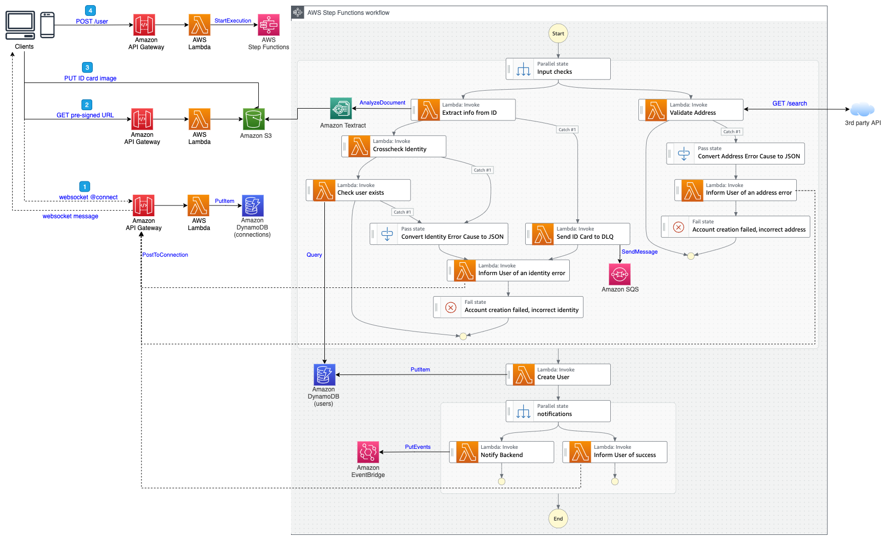
Figure 1 shows a typical workflow for the creation of an online bank account. The customer fills out a registration form with personal information and adds a picture of their ID card. The application then validates ID and address, and scans if there is already an existing user by that name. If everything checks out, a backend application will be notified to create the account. Finally, the user is notified of successful completion.

Figure 1. Bank account application workflow

Figure 1. Bank account application workflow

The workflow architecture is shown in Figure 2 (click on the picture to get full resolution).

Figure 2. Initial account creation architecture

Figure 2. Initial account creation architecture

This architecture contains 13 Lambda functions. If you look at the code on GitHub, you can see that:

Five of these Lambda functions are basic and perform simple operations:

Additional Lambda functions perform other tasks, such as verification and validation:

  • One function generates a presigned URL to upload ID card pictures to Amazon Simple Storage Service (Amazon S3)
  • One function uses the Amazon Textract API to extract information from the ID card
  • One function verifies the identity of the user against the information extracted from the ID card
  • One function performs simple HTTP request to a third-party API to validate the address

Finally, four functions concern the websocket (connect, message, and disconnect) and notifications to the user.

Opportunities for improvement

If you further analyze the code of the five basic functions (see startWorkflow on GitHub, for example), you will notice that there are actually three lines of fundamental code that start the workflow. The others 38 lines involve imports, input validation, error handling, logging, and tracing. Remember that all this code must be tested and maintained.

import os
import json
import boto3
from aws_lambda_powertools import Tracer
from aws_lambda_powertools import Logger
import re

logger = Logger()
tracer = Tracer()

sfn = boto3.client('stepfunctions')

PATTERN = re.compile(r"^arn:(aws[a-zA-Z-]*)?:states:[a-z]{2}((-gov)|(-iso(b?)))?-[a-z]+-\d{1}:\d{12}:stateMachine:[a-zA-Z0-9-_]+$")

if ('STATE_MACHINE_ARN' not in os.environ
    or os.environ['STATE_MACHINE_ARN'] is None
    or not PATTERN.match(os.environ['STATE_MACHINE_ARN'])):
    raise RuntimeError('STATE_MACHINE_ARN env var is not set or incorrect')

STATE_MACHINE_ARN = os.environ['STATE_MACHINE_ARN']

@logger.inject_lambda_context
@tracer.capture_lambda_handler
def handler(event, context):
    try:
        event['requestId'] = context.aws_request_id

        sfn.start_execution(
            stateMachineArn=STATE_MACHINE_ARN,
            input=json.dumps(event)
        )

        return {
            'requestId': event['requestId']
        }
    except Exception as error:
        logger.exception(error)
        raise RuntimeError('Internal Error - cannot start the creation workflow') from error

After running this workflow several times and reviewing the AWS X-Ray traces (Figure 3), we can see that it takes about 2–3 seconds when functions are warmed:

Figure 3. X-Ray traces when Lambda functions are warmed

Figure 3. X-Ray traces when Lambda functions are warmed

But the process takes around 10 seconds with cold starts, as shown in Figure 4:

Figure 4. X-Ray traces when Lambda functions are cold

Figure 4. X-Ray traces when Lambda functions are cold

We use an asynchronous architecture to avoid waiting time for the user, as this can be a long process. We also use WebSockets to notify the user when it’s finished. This adds some complexity, new components, and additional costs to the architecture. Now let’s look at how we can optimize this architecture.

Improving the initial architecture

Direct integration with Step Functions

Step Functions can directly integrate with some AWS services, including DynamoDB, Amazon SQS, and EventBridge, and more than 10,000 APIs from 200+ AWS services. With these integrations, you can replace Lambda functions when they do not provide value. We recommend using Lambda functions to transform data, not to transport data from one service to another.

In our bank account creation use case, there are four Lambda functions we can replace with direct service integrations (see large arrows in Figure 5):

  • Query a DynamoDB table to search for a user
  • Send a message to an SQS queue when the extraction fails
  • Create the user in DynamoDB
  • Send an event on EventBridge to notify the backend
Figure 5. Lambda functions that can be replaced

Figure 5. Lambda functions that can be replaced

It is not as clear that we need to replace the other Lambda functions. Here are some considerations:

  • To extract information from the ID card, we use Amazon Textract. It is available through the SDK integration in Step Functions. However, the API’s response provides too much information. We recommend using a library such as amazon-textract-response-parser to parse the result. For this, you’ll need a Lambda function.
  • The identity cross-check performs a simple comparison between the data provided in the web form and the one extracted in the ID card. We can perform this comparison in Step Functions using a Choice state and several conditions. If the business logic becomes more complex, consider using a Lambda function.
  • To validate the address, we query a third-party API. Step Functions cannot directly call a third-party HTTP endpoint, but because it’s integrated with API Gateway, we can create a proxy for this endpoint.

If you only need to retrieve data from an API or make a simple API call, use the direct integration. If you need to implement some logic, use a Lambda function.

Direct integration with API Gateway

API Gateway also provides service integrations. In particular, we can start the workflow without using a Lambda function. In the console, select the integration type “AWS Service”, the AWS service “Step Functions”, the action “StartExecution”, and “POST” method, as shown in Figure 6.

Figure 6. API Gateway direct integration with Step Functions

Figure 6. API Gateway direct integration with Step Functions

After that, use a mapping template in the integration request to define the parameters as shown here:

{
  "stateMachineArn":"arn:aws:states:eu-central-1:123456789012:stateMachine: accountCreationWorkflow",
  "input":"$util.escapeJavaScript($input.json('$'))"
}

We can go further and remove the websockets and associated Lambda functions connect, message, and disconnect. By using Synchronous Express Workflows and the StartSyncExecution API, we can start the workflow and wait for the result in a synchronous fashion. API Gateway will then directly return the result of the workflow to the client.

Final optimized architecture

After applying these optimizations, we have the updated architecture shown in Figure 7. It uses only two Lambda functions out of the initial 13. The rest have been replaced by direct service integrations or implemented in Step Functions.

Figure 7. Final optimized architecture

Figure 7. Final optimized architecture

We were able to remove 11 Lambda functions and their associated fees. In this architecture, the cost is mainly driven by Step Functions, and the main price difference will be your use of Express Workflows instead of Standard Workflows. If you need to keep some Lambda functions, use AWS Lambda Power Tuning to configure your function correctly and benefit from the best price/performance ratio.

One of the main benefits of this architecture is performance. With the final workflow architecture, it now takes about 1.5 seconds when the Lambda function is warmed and 3 seconds on cold starts (versus up to 10 seconds previously), see Figure 8:

Figure 8. X-Ray traces for the final architecture

Figure 8. X-Ray traces for the final architecture

The process can now be synchronous. It reduces the complexity of the architecture and vastly improves the user experience.

An added benefit is that by reducing the overall complexity and removing the unnecessary Lambda functions, we have also reduced the risk of failures. These can be errors in the code, memory or timeout issues due to bad configuration, lack of permissions, network issues between components, and more. This increases the resiliency of the application and eases its maintenance.

Testing

Testability is an important consideration when building your workflow. Unit testing a Lambda function is straightforward, and you can use your preferred testing framework and validate methods. Adopting a hexagonal architecture also helps remove dependencies to the cloud.

When removing functions and using an approach with direct service integrations, you are by definition directly connected to the cloud. You still must verify that the overall process is working as expected, and validate these integrations.

You can achieve this kind of tests locally using Step Functions Local, and the recently announced Mocked Service Integrations. By mocking service integrations, for example, retrieving an item in DynamoDB, you can validate the different paths of your state machine.

You also have to perform integration tests, but this is true whether you use direct integrations or Lambda functions.

Conclusion

This post describes how to simplify your architecture and optimize for performance, resiliency, and cost by using direct integrations in Step Functions and API Gateway. Although many Lambda functions were reduced, some remain useful for handling more complex business logic and data transformation. Try this out now by visiting the GitHub repository.

For further reading:

Author Spotlight: Seth Eliot, Principal Reliability Solutions Architect at AWS

Post Syndicated from Elise Chahine original https://aws.amazon.com/blogs/architecture/author-spotlight-seth-eliot-principal-reliability-solutions-architect-at-aws/

The Author Spotlight series pulls back the curtain on some of AWS’s most prolific authors. Read on to find out more about our very own Seth Eliot’s journey, in his own words!

At Amazon Web Services (AWS) and Amazon, we talk about “super powers” a lot. Everyone has them! I’ve discovered that mine is to take technical topics and make them actionable for builders and internal/external stakeholders at all levels.Seth Eliot

As Principal Reliability Solutions Architect for AWS Well-Architected, I work with customers on topics such as disaster recovery, assessing resilience, and chaos engineering. What I really enjoyabout this role is how much I learn every day. Customers always have new challenges, and I love finding new solutions for them. At events like AWS Global Summits or AWS re:Invent, I enjoy interacting with customers, such as when I run Chalk Talks, where I answer questions from the audience about reliability in the cloud.

Prior to joining AWS, I was a Solutions Architect for one of AWS’s biggest customers—Amazon.com! I traveled around the world to work hands-on with Amazon developers in places like Japan and Luxembourg to help modernize their workloads on AWS and get the most out of AWS technologies, like serverless and containers. Meeting face-to-face with folks and helping them use these technologies was really rewarding and very educational.

I’ve also worked as a Principal Engineer with Amazon Fresh grocery delivery and Amazon International Technology. These were two very different areas to work in, but they both have development teams all over the world that I was honored to help with their software design, agile development, and career guidance. By now, you’re likely noticing a pattern in my career…?

If you go back a bit further, I spent about 5 years working “across the lake” from Amazon HQ in Seattle, Washington, at Microsoft in Redmond during a really interesting moment in their history: moving, culturally and technically, from a “box product” company to one that creates software services. I am proud to have played a role in that move!

I am a “boomerang,” meaning that I actually was with Amazon prior to my time with Microsoft, and I came back. During my first stint here, I worked on the original team that launched what would become Prime Video. Back then, it was download-only experience (not streaming) and called “Amazon Unbox.” From where I sit now, it is amazing to see how the product has evolved.

Throughout these experiences, the thing that keeps me going is the opportunity to help builders and stakeholders to solve their hard problems. There is nothing more satisfying than after meeting with a person or team, getting feedback from them that I was able to help them.

Seth’s favorite posts!

What’s New in the Well-Architected Reliability Pillar?

My first AWS blog post! The real work was updating the AWS Well-Architected Reliability Pillar itself. I enjoyed collaborating with many smart experts across AWS to harness their diverse perspectives in the pillar update. Enjoy the read!

Disaster Recovery (DR) Architecture on AWS series

Figure 1. Disaster recovery (DR) options

Building Resilient Well-Architected Workloads Using AWS Resilience Hub

I was really excited by the release of AWS Resilience Hub (and was honored to be part of developing it). Finally, many of the best practices I talk about with customers are now automatically assessed against your workload with recommendations.

AWS Resilience Hub

Creating a Multi-Region Application with AWS Services series

Throttling a tiered, multi-tenant REST API at scale using API Gateway: Part 2

Post Syndicated from Nick Choi original https://aws.amazon.com/blogs/architecture/throttling-a-tiered-multi-tenant-rest-api-at-scale-using-api-gateway-part-2/

In Part 1 of this blog series, we demonstrated why tiering and throttling become necessary at scale for multi-tenant REST APIs, and explored tiering strategy and throttling with Amazon API Gateway.

In this post, Part 2, we will examine tenant isolation strategies at scale with API Gateway and extend the sample code from Part 1.

Enhancing the sample code

To enable this functionality in the sample code (Figure 1), we will make manual changes. First, create one API key for the Free Tier and five API keys for the Basic Tier. Currently, these API keys are private keys for your Amazon Cognito login, but we will make a further change in the backend business logic that will promote them to pooled resources. Note that all of these modifications are specific to this sample code’s implementation; the implementation and deployment of a production code may be completely different (Figure 1).

Cloud architecture of the sample code

Figure 1. Cloud architecture of the sample code

Next, in the business logic for thecreateKey(), find the AWS Lambda function in lambda/create_key.js.  It appears like this:

function createKey(tableName, key, plansTable, jwt, rand, callback) {
  const pool = getPoolForPlanId( key.planId ) 
  if (!pool) {
    createSiloedKey(tableName, key, plansTable, jwt, rand, callback);
  } else {
    createPooledKey(pool, tableName, key, jwt, callback);
  }
}

The getPoolForPlanId() function does a search for a pool of keys associated with the usage plan. If there is a pool, we “create” a kind of reference to the pooled resource, rather than a completely new key that is created by the API Gateway service directly. The lambda/api_key_pools.js should be empty.

exports.apiKeyPools = [];

In effect, all usage plans were considered as siloed keys up to now. To change that, populate the data structure with values from the six API keys that were created manually. You will have to look up the IDs of the API keys and usage plans that were created in API Gateway (Figures 2 and 3). Using the AWS console to navigate to API Gateway is the most intuitive.

A view of the AWS console when inspecting the ID for the Basic usage plan

Figure 2. A view of the AWS console when inspecting the ID for the Basic usage plan

A view of the AWS Console when looking up the API key value (not the ID)

Figure 3. A view of the AWS Console when looking up the API key value (not the ID)

When done, your code in lambda/api_key_pools.js should be the following, but instead of ellipses (), the IDs for the user plans and API keys specific to your environment will appear.

exports.apiKeyPools = [{
    planName: "FreePlan"
    planId: "...",
    apiKeys: [ "..." ]
  },
 {
    planName: "BasicPlan"
    planId: "...",
    apiKeys: [ "...", "...", "...", "...", "..." ]
  }];

After making the code changes, run cdk deploy from the command line to update the Lambda functions. This change will only affect key creation and deletion because of the system implementation. Updates affect only the user’s specific reference to the key, not the underlying resource managed by API Gateway.

When the web application is run now, it will look similar to before—tenants should not be aware what tiering strategy they have been assigned to. The only way to notice the difference would be to create two Free Tier keys, test them, and note that the value of the X-API-KEY header is unchanged between the two.

Now, you have a virtually unlimited number of users who can have API keys in the Free or Basic Tier. By keeping the Premium Tier siloed, you are subject to the 10,000-API-key maximum (less any keys allocated for the lower tiers). You may consider additional techniques to continue to scale, such as replicating your service in another AWS account.

Other production considerations

The sample code is minimal, and it illustrates just one aspect of scaling a Software-as-a-service (SaaS) application. There are many other aspects be considered in a production setting that we explore in this section.

The throttled endpoint, GET /api rely only on API key for authorization for demonstration purpose. For any production implementation consider authentication options for your REST APIs. You may explore and extend to require authentication with Cognito similar to /admin/* endpoints in the sample code.

One API key for Free Tier access and five API keys for Basic Tier access are illustrative in a sample code but not representative of production deployments. Number of API keys with service quota into consideration, business and technical decisions may be made to minimize noisy neighbor effect such as setting blast radius upper threshold of 0.1% of all users. To satisfy that requirement, each tier would need to spread users across at least 1,000 API keys. The number of keys allocated to Basic or Premium Tier would depend on market needs and pricing strategies. Additional allocations of keys could be held in reserve for troubleshooting, QA, tenant migrations, and key retirement.

In the planning phase of your solution, you will decide how many tiers to provide, how many usage plans are needed, and what throttle limits and quotas to apply. These decisions depend on your architecture and business.

To define API request limits, examine the system API Gateway is protecting and what load it can sustain. For example, if your service will scale up to 1,000 requests per second, it is possible to implement three tiers with a 10/50/40 split: the lowest tier shares one common API key with a 100 request per second limit; an intermediate tier has a pool of 25 API keys with a limit of 20 requests per second each; and the highest tier has a maximum of 10 API keys, each supporting 40 requests per second.

Metrics play a large role in continuously evolving your SaaS-tiering strategy (Figure 4). They provide rich insights into how tenants are using the system. Tenant-aware and SaaS-wide metrics on throttling and quota limits can be used to: assess tiering in-place, if tenants’ requirements are being met, and if currently used tenant usage profiles are valid (Figure 5).

Tiering strategy example with 3 tiers and requests allocation per tier

Figure 4. Tiering strategy example with 3 tiers and requests allocation per tier

An example SaaS metrics dashboard

Figure 5. An example SaaS metrics dashboard

API Gateway provides options for different levels of granularity required, including detailed metrics, and execution and access logging to enable observability of your SaaS solution. Granular usage metrics combined with underlying resource consumption leads to managing optimal experience for your tenants with throttling levels and policies per method and per client.

Cleanup

To avoid incurring future charges, delete the resources. This can be done on the command line by typing:

cd ${TOP}/cdk
cdk destroy

cd ${TOP}/react
amplify delete

${TOP} is the topmost directory of the sample code. For the most up-to-date information, see the README.md file.

Conclusion

In this two-part blog series, we have reviewed the best practices and challenges of effectively guarding a tiered multi-tenant REST API hosted in AWS API Gateway. We also explored how throttling policy and quota management can help you continuously evaluate the needs of your tenants and evolve your tiering strategy to protect your backend systems from being overwhelmed by inbound traffic.

Further reading:

Throttling a tiered, multi-tenant REST API at scale using API Gateway: Part 1

Post Syndicated from Nick Choi original https://aws.amazon.com/blogs/architecture/throttling-a-tiered-multi-tenant-rest-api-at-scale-using-api-gateway-part-1/

Many software-as-a-service (SaaS) providers adopt throttling as a common technique to protect a distributed system from spikes of inbound traffic that might compromise reliability, reduce throughput, or increase operational cost. Multi-tenant SaaS systems have an additional concern of fairness; excessive traffic from one tenant needs to be selectively throttled without impacting the experience of other tenants. This is also known as “the noisy neighbor” problem. AWS itself enforces some combination of throttling and quota limits on nearly all its own service APIs. SaaS providers building on AWS should design and implement throttling strategies in all of their APIs as well.

In this two-part blog series, we will explore tiering and throttling strategies for multi-tenant REST APIs and review tenant isolation models with hands-on sample code. In part 1, we will look at why a tiering and throttling strategy is needed and show how Amazon API Gateway can help by showing sample code. In part 2, we will dive deeper into tenant isolation models as well as considerations for production.

We selected Amazon API Gateway for this architecture since it is a fully managed service that helps developers to create, publish, maintain, monitor, and secure APIs. First, let’s focus on how Amazon API Gateway can be used to throttle REST APIs with fine granularity using Usage Plans and API Keys. Usage Plans define the thresholds beyond which throttling should occur. They also enable quotas, which sets a maximum usage per a day, week, or month. API Keys are identifiers for distinguishing traffic and determining which Usage Plans to apply for each request. We limit the scope of our discussion to REST APIs because other protocols that API Gateway supports — WebSocket APIs and HTTP APIs — have different throttling mechanisms that do not employ Usage Plans or API Keys.

SaaS providers must balance minimizing cost to serve and providing consistent quality of service for all tenants. They also need to ensure one tenant’s activity does not affect the other tenants’ experience. Throttling and quotas are a key aspect of a tiering strategy and important for protecting your service at any scale. In practice, this impact of throttling polices and quota management is continuously monitored and evaluated as the tenant composition and behavior evolve over time.

Architecture Overview

Figure 1. Cloud Architecture of the sample code.

Figure 1 – Architecture of the sample code

To get a firm foundation of the basics of throttling and quotas with API Gateway, we’ve provided sample code in AWS-Samples on GitHub. Not only does it provide a starting point to experiment with Usage Plans and API Keys in the API Gateway, but we will modify this code later to address complexity that happens at scale. The sample code has two main parts: 1) a web frontend and, 2) a serverless backend. The backend is a serverless architecture using Amazon API Gateway, AWS Lambda, Amazon DynamoDB, and Amazon Cognito. As Figure I illustrates, it implements one REST API endpoint, GET /api, that is protected with throttling and quotas. There are additional APIs under the /admin/* resource to provide Read access to Usage Plans, and CRUD operations on API Keys.

All these REST endpoints could be tested with developer tools such as curl or Postman, but we’ve also provided a web application, to help you get started. The web application illustrates how tenants might interact with the SaaS application to browse different tiers of service, purchase API Keys, and test them. The web application is implemented in React and uses AWS Amplify CLI and SDKs.

Prerequisites

To deploy the sample code, you should have the following prerequisites:

For clarity, we’ll use the environment variable, ${TOP}, to indicate the top-most directory in the cloned source code or the top directory in the project when browsing through GitHub.

Detailed instructions on how to install the code are in ${TOP}/INSTALL.md file in the code. After installation, follow the ${TOP}/WALKTHROUGH.md for step-by-step instructions to create a test key with a very small quota limit of 10 requests per day, and use the client to hit that limit. Search for HTTP 429: Too Many Requests as the signal your client has been throttled.

Figure 2: The web application (with browser developer tools enabled) shows that a quick succession of API calls starts returning an HTTP 429 after the quota for the day is exceeded.

Figure 2: The web application (with browser developer tools enabled) shows that a quick succession of API calls starts returning an HTTP 429 after the quota for the day is exceeded.

Responsibilities of the Client to support Throttling

The Client must provide an API Key in the header of the HTTP request, labelled, “X-Api-Key:”. If a resource in API Gateway has throttling enabled and that header is missing or invalid in the request, then API Gateway will reject the request.

Important: API Keys are simple identifiers, not authorization tokens or cryptographic keys. API keys are for throttling and managing quotas for tenants only and not suitable as a security mechanism. There are many ways to properly control access to a REST API in API Gateway, and we refer you to the AWS documentation for more details as that topic is beyond the scope of this post.

Clients should always test for the response to any network call, and implement logic specific to an HTTP 429 response. The correct action is almost always “try again later.” Just how much later, and how many times before giving up, is application dependent. Common approaches include:

  • Retry – With simple retry, client retries the request up to defined maximum retry limit configured
  • Exponential backoff – Exponential backoff uses progressively larger wait time between retries for consecutive errors. As the wait time can become very long quickly, maximum delay and a maximum retry limits should be specified.
  • Jitter – Jitter uses a random amount of delay between retry to prevent large bursts by spreading the request rate.

AWS SDK is an example client-responsibility implementation. Each AWS SDK implements automatic retry logic that uses a combination of retry, exponential backoff, jitter, and maximum retry limit.

SaaS Considerations: Tenant Isolation Strategies at Scale

While the sample code is a good start, the design has an implicit assumption that API Gateway will support as many API Keys as we have number of tenants. In fact, API Gateway has a quota on available per region per account. If the sample code’s requirements are to support more than 10,000 tenants (or if tenants are allowed multiple keys), then the sample implementation is not going to scale, and we need to consider more scalable implementation strategies.

This is one instance of a general challenge with SaaS called “tenant isolation strategies.” We highly recommend reviewing this white paper ‘SasS Tenant Isolation Strategies‘. A brief explanation here is that the one-resource-per-customer (or “siloed”) model is just one of many possible strategies to address tenant isolation. While the siloed model may be the easiest to implement and offers strong isolation, it offers no economy of scale, has high management complexity, and will quickly run into limits set by the underlying AWS Services. Other models besides siloed include pooling, and bridged models. Again, we recommend the whitepaper for more details.

Figure 3. Tiered multi-tenant architectures often employ different tenant isolation strategies at different tiers. Our example is specific to API Keys, but the technique generalizes to storage, compute, and other resources.

Figure 3- Tiered multi-tenant architectures often employ different tenant isolation strategies at different tiers. Our example is specific to API Keys, but the technique generalizes to storage, compute, and other resources.

In this example, we implement a range of tenant isolation strategies at different tiers of service. This allows us to protect against “noisy-neighbors” at the highest tier, minimize outlay of limited resources (namely, API-Keys) at the lowest tier, and still provide an effective, bounded “blast radius” of noisy neighbors at the mid-tier.

A concrete development example helps illustrate how this can be implemented. Assume three tiers of service: Free, Basic, and Premium. One could create a single API Key that is a pooled resource among all tenants in the Free Tier. At the other extreme, each Premium customer would get their own unique API Key. They would protect Premium tier tenants from the ‘noisy neighbor’ effect. In the middle, the Basic tenants would be evenly distributed across a set of fixed keys. This is not complete isolation for each tenant, but the impact of any one tenant is contained within “blast radius” defined.

In production, we recommend a more nuanced approach with additional considerations for monitoring and automation to continuously evaluate tiering strategy. We will revisit these topics in greater detail after considering the sample code.

Conclusion

In this post, we have reviewed how to effectively guard a tiered multi-tenant REST API hosted in Amazon API Gateway. We also explored how tiering and throttling strategies can influence tenant isolation models. In Part 2 of this blog series, we will dive deeper into tenant isolation models and gaining insights with metrics.

If you’d like to know more about the topic, the AWS Well-Architected SaaS Lens Performance Efficiency pillar dives deep on tenant tiers and providing differentiated levels of performance to each tier. It also provides best practices and resources to help you design and reduce impact of noisy neighbors your SaaS solution.

To learn more about Serverless SaaS architectures in general, we recommend the AWS Serverless SaaS Workshop and the SaaS Factory Serverless SaaS reference solution that inspired it.

Let’s Architect! Serverless architecture on AWS

Post Syndicated from Luca Mezzalira original https://aws.amazon.com/blogs/architecture/lets-architect-serverless-architecture-on-aws/

Serverless architecture and computing allow you and your teams to focus on delivering business value in place of investing time tweaking the infrastructure characteristics. AWS is not only providing serverless computing as a service, but share that half of our new applications built by Amazon are using AWS Lambda, as noted by Andy Jassy in his 2020 re:Invent keynote.

In this post, we share insights into reimagining a serverless environment.

I Build Applications – Event-driven Architecture

Event-driven architecture is common in modern applications built with microservices, and it is the cornerstone for designing serverless workloads. It uses events to trigger and communicate between decoupled services.

With this video, you can learn how to start with a prototype then scale to mass adoption using decoupled systems that run when responding to, without needing to redesign. Danilo Poccia, Chief Evangelist at AWS, begins the session with the APIs, then gives an example on how to build an event-driven architecture using Amazon EventBridge. The session closes with how to understand what is happening in this exchange of events.

Event-driven communication with asynchronous invocation

Event-driven communication with asynchronous invocation

Building modern cloud applications? Think integration

This re:Invent 2021 session explains modern cloud applications based on serverless or microservices, and how connections between components define important characteristics, like scalability, availability, and coupling.

How your systems are interconnected describes your system’s essential properties, such as resiliency and changeability. Gregor Hohpe, AWS Enterprise Strategist, shares tips on what to consider when integrating different services, such as lifecycle, level of control over the systems you are integrating, and how integration becomes an integral part of your software delivery cycle. The goal is to use the same method to integrate at the same speed as software deployment.

Integration approaches with Gregor Hohpe

Integration approaches with Gregor Hohpe

Serverless architectural patterns and best practices

Serverless architectures require a mindset shift: existing patterns need to be revisited, and new patterns created using the new architecture style. For each pattern created by AWS, we provide operational, security, and reliability best practices and discuss potential challenges. We also demonstrate some patterns in reference architecture diagrams.

This session helps you identify services and applications to create serverless architectures and understand areas of potential savings, increased agility, and reliability in your organization. Heitor Lessa, Principal Solutions Architect at AWS, starts the session identifying the benefits of Lambda Power Tuning: he details setting up memory when there are hundreds of functions, then follows with best practices for the pattern created.

Best practices for serverless architecture

Best practices for serverless architecture

Best practices of advanced serverless developers

This session is an overview of architectural best practices, optimizations, and handy codes that can be used to build secure, scalable, and high-performance serverless applications.

Julian Wood, Senior Developer Advocate at AWS, provides the recommended practices for implementing serverless applications inside your company, such as Lambda, to transform and not transport, avoid monolithic services and functions, orchestrate workflow with step functions, choreograph events. Julian also touches on understanding different ways you can invoke Lambda functions and what you should be aware of with each invocation model.

Three types of AWS Lambda invocation models

Three types of AWS Lambda invocation models

Building next-gen applications with event-driven architectures

Maintaining data consistency across multiple services can be challenging. It can also be difficult to work with large amounts of data in different data stores and locations. Teams building microservices architectures often find that integration with other applications and external services can make their workloads more monolithic and tightly coupled.

In this session, you can learn how to use event-based architectures to decouple and decentralize application components. Coupling is not one-dimensional, and it’s a trade-off to balance and optimize over time. This video demonstrates patterns based on message queues and events: for each pattern you can learn the advantages, the disadvantages, and the options for building it on AWS.

Sam Dengler, Principal Solutions Architect at AWS, explains the mental models to apply while designing choreography and orchestration in a scenario with microservices. The strategy adopted by Taco Bell for identifying their bounded contexts is also detailed, as well as the architecture built on Lambda for running the business logic and on AWS Step Functions for orchestration.

Choreography and orchestration are two modes of interaction in a microservices architecture

Choreography and orchestration are two modes of interaction in a microservices architecture

See you next time!

Thanks for joining our discussion on serverless architecting! If you want to deep dive into the topic, read all about Serverless on AWS!

See you in a couple of weeks when we discuss architecting for resilience!

Looking for more architecture content? AWS Architecture Center provides reference architecture diagrams, vetted architecture solutions, Well-Architected best practices, patterns, icons, and more!

Other posts in this series

Detecting data drift using Amazon SageMaker

Post Syndicated from Shibu Nair original https://aws.amazon.com/blogs/architecture/detecting-data-drift-using-amazon-sagemaker/

As companies continue to embrace the cloud and digital transformation, they use historical data in order to identify trends and insights. This data is foundational to power tools, such as data analytics and machine learning (ML), in order to achieve high quality results.

This is a time where major disruptions are not only lasting longer, but also happening more frequently, as discussed in a McKinsey article on risk and resilience. Any disruption—a pandemic, hurricane, or even blocked sailing routes—has a major impact on the patterns of data and can create anomalous behavior.

ML models are dependent on data insights to help plan and support production-ready applications. With any disruptions, data drift can occur. Data drift is unexpected and undocumented changes to data structure, semantics, and/or infrastructure. If there is data drift, the model performance will degrade and no longer provide an accurate guidance. To mitigate the effects of the disruption, data drift needs to be detected and the ML models quickly trained and adjusted accordingly.

This blog post explains how to approach changing data patterns in the age of disruption and how to mitigate its effects on ML models. We also discuss the steps of building a feedback loop to capture the request data in the production environment and create a data pipeline to store the data for profiling and baselining. Then, we explain how Amazon SageMaker Clarify can help detect data drift.

How to detect data drift

There are three stages to detecting data drift: data quality monitoring, model quality monitoring, and drift evaluation (see Figure 1).

Stages in detecting data drift

Figure 1. Stages in detecting data drift

Data quality monitoring establishes a profile of the input data during model training, and then continuously compares incoming data with the profile. Deviations in the data profile signal a drift in the input data.

You can also detect drift through model quality monitoring, which requires capturing actual values that can be compared with the predictions. For example, using weekly demand forecasting, you can compare the forecast quantities one week later with the actual demand. Some use cases can require extra steps to collect actual values. For example, product recommendations may require you to ask a selected group of consumers for their feedback to the recommendation.

SageMaker Clarify provides insights into your trained models, including importance of model features and any biases towards certain segments of the input data. Changes of these attributes between re-trained models also signal drift. Drift evaluation constitutes the monitoring data and mechanisms to detect changes and triggering consequent actions. With Amazon CloudWatch, you can define rules and thresholds that prompt drift notifications.

Figure 2 illustrates a basic architecture with the data sources for training and production (on the left) and the observed data concerning drift (on the right). You can use Amazon SageMaker Data Wrangler, a visual data preparation tool, to clean and normalize your input data for your ML task. You can store the features that you defined for your models in the Amazon SageMaker Feature Store, a fully managed, purpose-built repository to store, update, retrieve, and share ML features.

The white, rectangular boxes in the architecture diagram represent the tasks for detecting data and model drift. You can integrate those tasks into your ML workflow with Amazon SageMaker Pipelines.

Basic architecture on how data drift is detected using Amazon SageMaker

Figure 2. Basic architecture on how data drift is detected using Amazon SageMaker

The drift observation data can be captured in tabular format, such as comma-separated values or Parquet, on Amazon Simple Storage Service (S3) and analyzed with Amazon Athena and Amazon QuickSight.

How to build a feedback loop

The baselining task establishes a data profile from training data. It uses Amazon SageMaker Model Monitor and runs before training or re-training the model. The baseline profile is stored on Amazon S3 to be referenced by the data drift monitoring job.

The data drift monitoring task continuously profiles the input data, compares it with baseline, and the results are captured in CloudWatch. This tasks runs on its own computation resources using Deequ, which checks that the monitoring job does not slow down your ML inference flow and scales with the data. The frequency of running this task can be adjusted to control cost, which can depend on how rapidly you anticipate that the data may change.

The model quality monitoring task computes model performance metrics from actuals and predicted values. The origin of these data points depends on the use case. Demand forecasting use cases naturally capture actuals that can be used to validate past predictions. Other use cases can require extra steps to acquire ground-truth data.

CloudWatch is a monitoring and observability service with which you can define rules to act on deviation in model performance or data drift. With CloudWatch, you can setup alerts to users via e-mail or SMS, and it can automatically start the ML model re-training process.

Run the baseline task on your updated data set before re-training your model. Use the SageMaker model registry to catalog your ML models for production, manage model versions, and control the associate training metrics.

Gaining insight into data and models

SageMaker Clarify provides greater visibility into your training data and models, helping identify and limit bias and explain predictions. For example, the trained models may consider some features more strongly than others when generating predictions. Compare the feature importance and bias between model-provided versions for a better understanding of the changes.

Conclusion

As companies continue to use data analytics and ML to inform daily activity, data drift may become a more common occurrence. Recognizing that drift can have a direct impact on models and production-ready applications, it is important to architect to identify potential data drift and avoid downgrading the models and negatively impacting results. Failure to capture changes in data can result in loss of process confidence, downgraded model accuracy, or a bottom-line impact to the business.

Architecting for sustainability: a re:Invent 2021 recap

Post Syndicated from Margaret O'Toole original https://aws.amazon.com/blogs/architecture/architecting-for-sustainability-a-reinvent-2021-recap/

At AWS re:Invent 2021, we announced the AWS Well-Architected Sustainability Pillar, which marks sustainability as a key pillar of building workloads to best deliver on business need. In session ARC325 – Architecting for Sustainability, Adrian Cockcroft, Steffen Grunwald, and Drew Engelson (Director of Engineering at Starbucks) gave a detailed explanation of what to expect from the Sustainability Pillar whitepaper and how Starbucks has applied AWS best practices to their workloads.

AWS is committed to building a sustainable business for our customers and the planet. Amazon co-founded The Climate Pledge in 2019, committing to reach net-zero carbon by the Year 2040 — 10 years ahead of the Paris Agreement. As part of reaching our commitment, Amazon is on a path to powering our operations with 100% renewable energy by 2025 — 5 years ahead of our original target of 2030.

In 2020, we became the world’s largest corporate purchaser of renewable energy, reaching 65% renewable energy across our business. Amazon also continues to invest in renewable energy projects paired with energy storage: the energy storage systems allow Amazon to store clean energy produced by its solar projects and deploy it when solar energy is unavailable, such as in the evening hours, or during periods of high demand. This strengthens the climate impact of Amazon’s clean energy portfolio by enabling carbon-free electricity throughout more parts of the day.

As customers architect solutions with AWS services to fulfill their business needs, they also influence the sustainability of a workload. AWS had published five pillars in the AWS Well-Architected Framework that capture best practices for operational excellence, security, reliability, performance, and cost of workloads. These pillars have supported the business need for faster time-to-value for features and the delivery of products.

In light of the climate crisis, we have a new challenge to help businesses optimize their application architectures and workloads for sustainability. With sustainability as the sixth pillar in the AWS Well-Architected Framework, builders have guidance to optimize their workloads for energy reduction and efficiency improvement across all components of a workload.

How Starbucks is reducing their footprint

Starbucks has set very ambitious sustainability goals to reduce the environmental impact of their business. As Drew Engelson mentioned in his presentation, there was a gap between these major goals and how members of the technology teams could participate in this mission. Drew decided to evaluate the systems his team was responsible for and initiated an internal framework for understanding the environmental impact of the systems.

Sustainability proxy metrics based on service usage, as demonstrated in the AWS Well-Architected Lab for Sustainability, complemented AWS customer carbon footprint tool data to help the team drive reductions. The goal was to snap a baseline and identify areas for further optimization. The Starbucks team applied the Well-Architected Sustainability Pillar best practices after performing an AWS Well-Architected review early in the process.

Through working with AWS, Starbucks saw that from 2019 to 2020, the actual carbon footprint of their AWS workloads was reduced by approximately 32%, despite tremendous business growth during that same period. The customer carbon footprint tool indicates that these systems’ carbon footprint was further reduced by 50% in subsequent quarters.

Optimizing beyond cost

The Starbucks team already optimized their workloads for cost efficiency, leading to high energy and resource efficiency. Starbucks relies heavily on Kubernetes, which allows them to densely pack their services onto the underlying infrastructure, yielding very high utilization. Binary protocols, like gRPC, are used for efficient communication between microservices. This also cuts down on the data transfer between different networks. Many of their services are written in efficient Scala code, which adds another layer of optimization to the workload.

By taking a data-driven approach, Drew and his team at Starbucks also were able to review scaling thresholds. Based on data, they were able to adjust the auto scaling curve much more closely and smoothly, matching the actual demand curve and reducing the resources they needed to provision.

Drew’s team went beyond the initial optimization cost-benefits to sustainability of the whole stack. They identified workloads suitable for Amazon EC2 Spot Instances to leverage unused, on-demand capacity and increase the overall resource utilization of the cloud. The Starbucks team is starting to examine the impact of their mobile application to end-user devices, and they are taking steps to reduce the downstream impacts: for example, considering the size of client-side scripts, devices’ CPU usage, and color scheme (dark mode reduces the energy required for certain display types).

Starbucks takes optimization for sustainability seriously—so seriously that they coined the term “TCO2”, which highlights the importance climate impact when measuring Total Costs of Ownership (Figure). Drew raised an important question for application teams and architects that frequently make tradeoffs for cost benefits:

If carbon was the thing we’re optimizing for, would we make different choices?

Drew Engelson, Director of Engineering at Starbucks, discussing "TCO2"

Figure. Drew Engelson, Director of Engineering at Starbucks, discussing “TCO2

Get started, the sustainable way

At AWS, we encourage architects to build solutions with sustainability in mind. If your team wants to get started with the concepts from the AWS Well-Architected Sustainability Pillar, conduct a review of your workload in the Well-Architected Tool, or check out the AWS Well-Architected Framework and AWS Well-Architected Labs to learn more!

Ask an Expert – Sustainability

Post Syndicated from Margaret O'Toole original https://aws.amazon.com/blogs/architecture/ask-an-expert-sustainability/

In this first edition of Ask an Expert, we chat with Margaret O’Toole, Worldwide Tech Leader – Environmental Sustainability and Joseph Beer, Worldwide Tech Leader – Power and Utilities about sustainability solutions and tools to implement sustainability practices into IT design.

When putting together an AWS architecture to solve business problems specifically for sustainability-focused customers, what are some of the considerations?

A core idea of sustainability comes down to efficiency: how can we do the most work with the fewest number of resources? In this case, you want efficiency when you design and build the solution and also when you apply and operate it.

In broad strokes, there are two main things to consider. First, you want to optimize technology usage to reduce impact. Second, you want to find and use the best mix of technology to support sustainability. These objectives must also delight your customers, constituents, and stakeholders as you meet your business objectives in the most cost effective and expeditious way possible.

However, to be successful in combining technology and sustainability, you must consider the culture change of the sustainability transformation. Sustainability must become part of each person’s job function. When it comes to responsibility around sustainability at AWS, we think about it through two lenses.

First, we have the sustainability OF the AWS Cloud, which is our responsibility at AWS. This covers the work we do around purchasing renewable energy, operating efficiently, reducing water consumption in the data centers, and so on. There is more information on sustainability of the AWS Cloud on our sustainability page.

Then, there’s sustainability IN the cloud, which focuses on customers and their AWS usage. This is again focused on efficiency, mostly how to optimize existing patterns of user consumption, data access, software and development patterns, and hardware utilization.

In a related but slightly different vein, we also talk about sustainability THROUGH the cloud. This is how our customers use AWS to work on sustainability projects that help them meet their sustainability goals. This can include anything from carbon tracking or accounting to route optimization for fleets to using machine learning (ML) to reduce packaging and anything in between.

What are the general architecture pattern trends for sustainability in the cloud?

Solutions designed with sustainability in mind aim to be highly efficient. An architect wanting to optimize for sustainability looks for opportunities within user patterns, software patterns, development/test patterns, hardware patterns, and data patterns.

There is no one-size-fits-all way to optimize for sustainability, but the core themes are maximizing utilization and reducing waste or duplication. Most customers start with relatively easy things to accomplish. These typically include things like using the AWS Instance Scheduler to turn off compute when it will not be used or comparing cost and utilization reports to find hot spots to reduce utilization.

Another way to optimize for sustainability is to incorporate AWS Managed Services (AMS) as much as possible (many of these are also serverless). AMS not only increases the speed and efficiency of your design and build time and lower your overhead to run, but they also include automatic scaling as part of the service, which increases compute efficiency. Where AMS is not applicable, you can often configure automatic scaling into the solutions themselves. Automate everything, including your continuous integration and continuous delivery/deployment (CI/CD) code pipeline, data analytics and artificial intelligence (AI)/ML pipelines, and infrastructure builds where you are not using AMS.

And finally, include ongoing AWS Well-Architected reviews and continuously review and optimize your usage of AMS and the size and mix of your compute and storage in your standard operating procedures.

What are the key AWS-based sustainability solutions you are seeing customers ask for across industries and unique to specific industries?

Almost all industries have a set of shared challenges. This generally includes things like facilities or building management, design or optimization, and carbon tracking/footprinting. To help with this, customers must first understand the impact of their facilities, operations, or supply chain. Many customers use AWS services for ingestion, aggregation, and transformation of their real-world data. Once the data is collected and customers understand their relative impact, this data can be used to form models, which act as the basis for optimization. Technologies such as AWS IoT Core, Amazon Managed Blockchain, and AWS Lake Formation are crucial here.

For industries like power and utilities, there are more targeted solutions. Many of these are aimed at supporting the transition to electric vehicles (EVs). Smart EV charging, for example, uses the AWS Cloud and AI/ML to lessen the aggregate impact to the grid that may occur because of EV charging peaks and ramp ups. This helps avoid requiring natural gas at peak times. Amazon Forecast, a fully managed service that delivers highly accurate forecasts, can be useful in the case of short-term electric load forecasting. Grid voltage optimization is another solution that allows utilities to forecast usage requests and more accurately provide the desired voltage to their customers.

Within supply chains, customers use AWS to support traceability and carbon dashboarding to nudge suppliers toward greener energy. Customers commonly look for ways to track and trace throughout their supply chains, either to measure and reduce scope 3 emissions or to optimize their logistics network.

What’s your outlook for sustainability, and what role will the cloud play in future development efforts?

The cloud is critical to solving sustainability challenges that businesses and governments are being challenged with right now. It gives you the flexibility to use resources only when you need them, coupled with immense computing power. Thus, the cloud will be an essential tool in solving many data challenges like reporting and measuring and predicting and analyzing trends.

Migration to the cloud is essential to optimizing workloads and handling massive amounts of data. We can see this directly in how Boom used AWS HPC to support the creation of the world’s fastest and most sustainable aircraft. Additionally, FLSmidth is pursuing sustainable, technology-driven productivity under MissionZero. This initiative is working to achieve zero emissions and zero waste in cement production and mining by 2030 with the help of AWS high performance computing (HPC).

Do you see different trends in sustainability in the cloud versus on-premises?

The usage pattern is different. With the cloud you can use what you want, whenever you want, which allows for customers to drive up a high utilization. This type of efficiency is critical. It’s why 451 Research found that the same task can be completed on AWS with an 88% lower carbon footprint compared to the average surveyed US enterprise data center.

The cloud offers technology that wouldn’t be available on premises, such as large GPU-backed instances capable of processing huge amounts of data in hours that would take weeks on premises. It can also ingest massive streams of data from energy- and resource-consuming and producing assets to optimize their performance and environmental impact in near-real-time.

With the cloud, you have the flexibility and the power to move quickly through research and development to solve sustainability challenges. You can accelerate the development process of new ideas and solutions, which will be essential for the transformation to a carbon neutral, climate positive economy.

A collection of posts to help you design and build sustainable cloud architecture

Post Syndicated from Bonnie McClure original https://aws.amazon.com/blogs/architecture/a-collection-of-posts-to-help-you-design-and-build-sustainable-cloud-architecture/

We’re celebrating Earth Day 2022 from 4/22 through 4/29 with posts that highlight how to build, maintain, and refine your workloads for sustainability.


A blog can be a great starting point for you in finding and implementing a particular solution; learning about new features, services, and products; keeping up with the latest trends and ideas; or even understanding and resolving a tricky problem. Today, as part of our Earth Day celebration, we’re showcasing blog posts that do just that and more.

Optimize AI/ML workloads for sustainability series

Training artificial intelligence (AI) services and machine learning (ML) workloads uses a lot of energy, but they are also one of the best tools we have to fight the effects of climate change. For example, we’ve used ML to help deliver food and pharmaceuticals safely and with much less waste, reduce the cost and risk involved in maintaining wind farms, restore at-risk ecosystems, and predict and understand extreme weather.

In this series of three blog posts, Benoit, Eddie, Dan, and Brendan provide guidance from the Sustainability Pillar of the AWS Well-Architected Framework to reduce the carbon footprint of your AI/ML workloads.

ML lifecycle

Machine learning lifecycle

Improve workload sustainability with services and features from re:Invent 2021

Creating a well-architected, sustainable workload is a continuous process. This blog post highlight services and features from re:Invent 2021 that will help you design and optimize your AWS workloads from a sustainability perspective.

Optimizing Your IoT Devices for Environmental Sustainability

To become more environmentally sustainable, customers commonly introduce Internet of Things (IoT) devices. These connected devices collect and analyze data from commercial buildings, factories, homes, cars, and other locations to measure, understand, and improve operational efficiency. However, you must consider their environmental impact when using these devices. They must be manufactured, shipped, and installed; they consume energy during operations; and they must eventually be disposed of. They are also a challenge to maintain—an expert may need physical access to the device to diagnose issues and update it. This post considers device properties that influence an IoT device’s footprint throughout its lifecycle and shows you how Amazon Web Services (AWS) IoT services can help.

Let’s Architect! Architecting for Sustainability

This first post in the Let’s Architect! series gathers content to help software architects and tech leaders explore new ideas, case studies, and technical approaches. Luca, Laura, Vittori, and Zamira provide materials to help you address sustainability challenges and design sustainable architectures.

Optimizing your AWS Infrastructure for Sustainability Series

As organizations align their business with sustainable practices, it is important to review every functional area. If you’re building, deploying, and maintaining an IT stack, improving its environmental impact requires informed decision making.

This three-part blog series provides strategies to optimize your AWS architecture within compute, storage, and networking.

The shared responsibility model for sustainability shows how it is a shared responsibility between AWS and customers

The shared responsibility model for sustainability shows how it is a shared responsibility between AWS and customers

IBM Hackathon Produces Innovative Sustainability Solutions on AWS

Our consulting partner, IBM, organized the “Sustainability Applied 2021” hackathon in September 2021. This three-day event aimed to generate new ideas, create reference architecture patterns using AWS Cloud services, and produce sustainable solutions.

This post highlights four reference architectures that were developed during the hackathon. These architectures show you how IBM hack teams used AWS services to resolve real-world sustainability challenges. We hope these architectures inspire you to help address other sustainability challenges with your own solutions.

Let’s Architect! Using open-source technologies on AWS

Post Syndicated from Luca Mezzalira original https://aws.amazon.com/blogs/architecture/lets-architect-using-open-source-technologies-on-aws/

With open-source technology, authors make software available to the public, who can view, use, or change it and add new features or support new capabilities. Open-source technology promotes collaboration across different teams, organizations, and people because the process often includes different perspectives and ideas, which typically results a stronger solution.

It can be difficult to create a multi-use solution when building to solve for a specific challenge. With an open-source project or an initiative, multiple teams work together, which prevents coupling and makes the solution easier to generalize.

In this edition of Let’s Architect!, we show you some open-source technologies built with AWS and options for running well-known, open-source projects on AWS.

Firecracker: Secure and Fast microVMs for Serverless Computing

Firecracker was developed at AWS to improve the customer experience of services like AWS Lambda and AWS Fargate. This technology is used to deploy workloads in lightweight virtual machines (VMs), called microVMs. For example, when a new Lambda function is triggered in response to an event, AWS Lambda provisions a microVM (if none already exists) to handle the request. Behind the scenes, this is powered by Firecracker.

This video introduces Firecracker and the concept of virtual machine monitor as a technology to create and manage microVMs. This talk explains Firecracker’s foundation, the minimal device model, and how it interacts with various containers. You’ll learn about the performance, security, and utilization improvements enabled by Firecracker and how Firecracker is used for Lambda and Fargate.

An example host running Firecracker microVMs

An example host running Firecracker microVMs

Deep dive into AWS Cloud Development Kit

AWS Cloud Development Kit (CDK) is an open-source software development framework that allows you to define your cloud application resources using familiar programming languages. It uses object-oriented design to create resources and build an end-to-end process for application development from infrastructure and software-development perspectives.

This video introduces AWS CDK core concepts and demonstrates how to create custom resources and deploy them to the cloud. With AWS CDK, you can make deployments repeatable, automate operations through infrastructure as code, and use the software design patterns while coding your architecture.

AWS CDK is an open-source software development framework for defining cloud infrastructure as code

AWS CDK is an open-source software development framework for defining cloud infrastructure as code

Using Apollo Server on AWS Lambda with Amazon EventBridge for real-time, event-driven streaming

Apollo Server is an open-source, spec-compliant GraphQL server that’s compatible with any GraphQL client. This blog posts covers how you can architect Apollo Server on AWS Lambda in an event-driven architecture. It shows you how to use the Apollo Server on AWS Lambda, integrate it with REST and WebSocket APIs and communicate asynchronously via event bus.

Sample application: a chat app that receives a text message from the client and responds with French and German translations of the message

Sample application: a chat app that receives a text message from the client and responds with French and German translations of the message

Observability the open-source way

Removing the undifferentiated heavy lifting for implementing open-source software can allow you to plug-and-play your favorite solutions with existing AWS services. This video addresses best practices and real-world use cases for Amazon Managed Service for Prometheus, Amazon Managed Grafana, and AWS Distro for OpenTelemetry to gain observability. Observability is fundamental to collect and analyze data coming from your architecture, understand the status of your system, and take action to improve application performance.

Setting up Amazon Managed Service for Prometheus

Setting up Amazon Managed Service for Prometheus

See you next time!

See you in a couple of weeks when we discuss strategies for running serverless applications on AWS!

Looking for more architecture content? AWS Architecture Center provides reference architecture diagrams, vetted architecture solutions, Well-Architected best practices, patterns, icons, and more!

Other posts in this series

Building SAML federation for Amazon OpenSearch Dashboards with Ping Identity

Post Syndicated from Raghavarao Sodabathina original https://aws.amazon.com/blogs/architecture/building-saml-federation-for-amazon-opensearch-dashboards-with-ping-identity/

Amazon OpenSearch is an open search and log analytics service, powered by the Apache Lucene search library.

In this blog post, we provide step-by-step guidance for SP-initiated SSO by showing how to set up a trial Ping Identity account. We’ll show how to build users and groups within your organization’s directory and enable SSO in OpenSearch Dashboards.

To use this feature, you must enable fine-grained access control. Rather than authenticating through Amazon Cognito or the internal user database, SAML authentication for OpenSearch Dashboards lets you use third-party identity providers to log in.

Ping Identity is an AWS Competency Partner, and the provider of the PingOne Cloud Platform is a multi-tenant Identity-as-a-Service (IDaaS) platform. Ping Identity supports both service provider (SP)-initiated and identity provider (IdP)-initiated SSO.

Overview of Ping Identity SAML authenticated solution

Figure 1 shows a sample architecture of a generic integrated solution between Ping Identity and OpenSearch Dashboards over SAML authentication.

SAML transactions between Amazon OpenSearch and Ping Identity

Figure 1. SAML transactions between Amazon OpenSearch and Ping Identity

The sign-in flow is as follows:

  1. User opens browser window and navigates to Amazon OpenSearch Dashboards
  2. Amazon OpenSearch generates SAML authentication request
  3. Amazon OpenSearch redirects request back to browser
  4. Browser redirects to Ping Identity URL
  5. Ping Identity parses SAML request, authenticates user, and generates SAML response
  6. Ping Identity returns encoded SAML response to browser
  7. Browser sends SAML response back to Amazon OpenSearch Assertion Consumer Service (ACS) URL
  8. ACS verifies SAML response
  9. User logs into Amazon OpenSearch domain

Prerequisites

For this walkthrough, you should have the following prerequisites:

  1. An AWS account
  2. A virtual private cloud (VPC)-based Amazon OpenSearch domain with fine-grained access control enabled
  3. Ping Identity account with user and a group
  4. A browser with network connectivity to Ping Identity, Amazon OpenSearch domain, and Amazon OpenSearch Dashboards.

The steps in this post are structured into the following sections:

  1. Identity provider (Ping Identity) setup
  2. Prepare Amazon OpenSearch for SAML configuration
  3. Identity provider (Ping Identity) SAML configuration
  4. Finish Amazon OpenSearch for SAML configuration
  5. Validation
  6. Cleanup

Identity provider (Ping Identity) setup

Step 1: Sign up for a Ping Identity account

  • Sign up for a Ping Identity account, then click on the Sign up button to complete your account setup.
  • If you already have an account with Ping Identity, login to your Ping Identity account.

Step 2: Create Population in Ping Identity

  • Choose Identities in the left menu and click Populations to proceed.
  • Click on the blue + button next to Populations, enter the name as IT, then click on the Save button (see Figure 2).
Creating population in Ping Identity

Figure 2. Creating population in Ping Identity

Step 3: Create a group in Ping Identity

  • Choose Groups from the left menu and click on the blue + button next to Groups. For this example, we will create a group called opensearch for Kibana access. Click on the Save button to complete the group creation.

Step 4: Create users in Ping Identity

  • Choose Users in left menu, then click the + Add User button.
  • Provide GIVEN NAME, FAMILY NAME, EMAIL ADDRESS, and choose Population as users, as created in Step 1. Choose your own USERNAME. Click on the SAVE button to create your user.
  • Add more users as needed.

Step 5: Assign role and group to users

  • Click on Identities/users in the left menu, and click on Users. Then click on the edit button for a particular user, as shown in Figure 3.
Assigning roles and groups to users in Ping Identity

Figure 3. Assigning roles and groups to users in Ping Identity

  • Click on the Edit button, click on + Add Role button, and click on the edit button to assign a role to the user.
  • For this example, choose Environment Admin, as shown in Figure 4. You can choose different roles depending on your use case.
Assigning roles to users in Ping Identity

Figure 4. Assigning roles to users in Ping Identity

  • For this example, assign administrator responsibilities for our users. Click on Show Environments, and drag Administrators into the ADDED RESPONSIBILITES section. Then click on the Add Role button.
  • Add Group to users. Go to the Groups tab, search for the opensearch group created in Step 3. Click on the + button next to opensearch to add into group memberships.

Prepare Amazon OpenSearch for SAML configuration

Once the Amazon OpenSearch domain is up and running, we can proceed with configuration.

  • Under Actions, choose Edit security configuration, as shown in Figure 5.
Enabling Amazon OpenSearch security configuration for SAML

Figure 5. Enabling Amazon OpenSearch security configuration for SAML

  • Under SAML authentication for OpenSearch Dashboards/Kibana, select Enable SAML authentication check box (Figure 6). When we enable SAML, it will create different URLs required for configuring SAML with your identity provider.
Amazon OpenSearch URLs for SAML configuration

Figure 6. Amazon OpenSearch URLs for SAML configuration

We will be using the Service Provider entity ID and SP-initiated SSO URL as highlighted in Figure 6 for Ping Identity SAML configuration. We will complete the rest of the Amazon OpenSearch SAML configuration after the Ping Identity SAML configuration.

Ping Identity SAML configuration

Go back to PingIdentity.com, and navigate to Connections on the left menu. Then select Applications, and click on Application +.

  • For this example, we are creating an application called “Kibana”
  • Select WEB APP as APPLICATION TYPE and CHOOSE CONNECTION TYPE as SAML, and click on Configure button to proceed as shown in Figure 7.
Configuring a new application in Ping Identity

Figure 7. Configuring a new application in Ping Identity

  • On the “Create App Profile” page, click on the Next button, and choose the “Manually Enter” option for PROVIDE APP METADATA. Enter the following under Configure SAML Connection section
    • ACS URL https://vpc-XXXXX-XXXXX-west-2.es.amazonaws.com/_dashboards/_opendistro/_security/saml/acs (SP-initiated SSO URL)
    • Choose Sign Assertion & Response under SIGNING KEY
    • ENTITY ID: https://vpc-XXXXX-XXXXX.us-west-2.es.amazonaws.com (Service provider entity ID)
    • ASSERTION VALIDITY DURATION (IN SECONDS) as 3600
    • Choose default options, then click on the Save and Continue button as shown in Figure 8
Configuring SAML connection in Ping Identity

Figure 8. Configuring SAML connection in Ping Identity

  • Enter the following under Configure Attribute Mapping, then click on Save and Close.
    • Set User ID to default
    • Click on +ADD ATTRIBUTE button to add following SAML attributes
      • OUTGOING VALUE: Group Names, SAML ATTRIBUTE: saml_group
      • OUTGOING VALUE: Username, SAML ATTRIBUTE: saml_username
  • Select the Policies tab and click on edit icon on the right.
  • Add the Single_Factor policy to the application, then click on Save.
  • Select the Access tab, add the opensearch group to the application, then click on Save to complete SAML configuration.
  • Finally, go to the Configuration tab, click on the Download Metadata button to download the Ping Identity metadata for the Amazon OpenSearch SAML configuration. Enable opensearch SAML application (Figure 9).
Downloading metadata in Ping Identity

Figure 9. Downloading metadata in Ping Identity

Amazon OpenSearch SAML configuration

  • Switch back to Amazon OpenSearch domain:
    • Navigate to the Amazon OpenSearch console.
    • Click on Actions, then click on Modify Security configuration.
    • Select the Enable SAML authentication check box.
  • Under Import IdP metadata section:
    • Metadata from IdP: Import the Ping Identity identity provider metadata from the downloaded XML file, shown in Figure 10.
    • SAML master backend role: opensearch (Ping Identity group). Provide SAML backend role/group SAML assertion key for group SSO into Kibana.
Configuring Amazon OpenSearch SAML parameters

Figure 10. Configuring Amazon OpenSearch SAML parameters

  • Under Optional SAML settings:
    • Leave the Subject Key as saml_subject from Ping Identity SAML application attribute name.
    • Role key should be saml_group. You can view a sample assertion during the configuration process by tools like SAML-tracer. This can help you examine and troubleshoot the contents of real assertions.
    • Session time to live (mins): 60
  • Click on the Submit button to complete Amazon OpenSearch SAML configuration for Kibana. We have successfully completed SAML configuration and are now ready for testing.

Validating Access with Ping Identity Users

  • The OpenSearch Dashboards URL can be found in the Overview tab within “General Information” in the Amazon OpenSearch console (Figure 11). The first access to the OpenSearch Dashboards URL redirects you to the Ping Identity login screen.
Validating Ping Identity users access with Amazon OpenSearch

Figure 11. Validating Ping Identity users access with Amazon OpenSearch

  • If your OpenSearch domain is hosted within a private VPC, you will not be able to access OpenSearch Dashboards over public internet. But you can still use SAML as long as your browser can communicate with both your OpenSearch cluster and your identity provider.
  • You can create a Mac or Windows EC2 instance within the same VPC and access Amazon OpenSearch Dashboards from an EC2 instance’s web browser to validate your SAML configuration. Or you can access your Amazon OpenSearch Dashboards through Site-to-Site VPN if you are trying to access it from your on-premises environment.
  • Now copy and paste the OpenSearch Dashboards URL in your browser, and enter user credentials.
  • After successful login, you will be redirected into the OpenSearch Dashboards home page. Explore our sample data and visualizations in OpenSearch Dashboards, as shown in Figure 12.
SAML authenticated Amazon OpenSearch Dashboards

Figure 12. SAML authenticated Amazon OpenSearch Dashboards

  • You have successfully federated Amazon OpenSearch Dashboards with Ping Identity as an identity provider. You can connect OpenSearch Dashboards by using your Ping Identity credentials.

Cleaning up

After you test out this solution, remember to delete all the resources you created to avoid incurring future charges. Refer to these links:

Conclusion

In this blog post, we have demonstrated how to set up Ping Identity as an identity provider over SAML authentication for Amazon OpenSearch Dashboards access. With this solution, you now have an OpenSearch Dashboard that uses Ping Identity as the custom identity provider for your users. This reduces the customer login process to one set of credentials and improves employee productivity.

Get started by checking the Amazon OpenSearch Developer Guide, which provides guidance on how to build applications using Amazon OpenSearch for your operational analytics.

Building SAML federation for Amazon OpenSearch Service with Okta

Post Syndicated from Raghavarao Sodabathina original https://aws.amazon.com/blogs/architecture/building-saml-federation-for-amazon-opensearch-dashboards-with-okta/

Amazon OpenSearch Service is a fully managed open search and analytics service powered by the Apache Lucene search library. Security Assertion Markup Language (SAML)-based federation for OpenSearch Dashboards lets you use your existing identity provider (IdP) like Okta to provide single sign-on (SSO) for OpenSearch Dashboards on OpenSearch Service domains.

This post shows step-by-step guidance to enable SP-initiated single sign-on (SSO) into OpenSearch Dashboards using Okta.

To use this feature, you must enable fine-grained access control. Rather than authenticating through Amazon Cognito or the internal user database, SAML authentication for OpenSearch Dashboards lets you use third-party identity providers to log in to OpenSearch Dashboards. SAML authentication for OpenSearch Dashboards is only for accessing OpenSearch Dashboards through a web browser.

Overview of Okta SAML authenticated solution

Figure 1 depicts a sample architecture of a generic, integrated solution between Okta and OpenSearch Dashboards over SAML authentication.

SAML transactions between Amazon OpenSearch Service and Okta

Figure 1. SAML transactions between Amazon OpenSearch Service and Okta

The initial sign-in flow is as follows:

  1. User opens browser window and navigates to OpenSearch Dashboards
  2. OpenSearch Service generates SAML authentication request
  3. OpenSearch Service redirects request back to browser
  4. Browser redirects to Okta URL
  5. Okta parses SAML request, authenticates user, and generates SAML response
  6. Okta returns encoded SAML response to browser
  7. Browser sends SAML response back to OpenSearch Service Assertion Consumer Services (ACS) URL
  8. ACS verifies SAML response
  9. User logs into OpenSearch Service domain

Prerequisites

For this walkthrough, you should have the following prerequisites:

  1. An AWS account
  2. A virtual private cloud (VPC)-based OpenSearch Service domain with fine-grained access control enabled
  3. Okta account with user and a group
  4. A browser with network connectivity to Okta, OpenSearch Service domain, and OpenSearch Dashboards.

The steps in this post are structured into the following sections:

  1. Identity provider (Okta) setup
  2. Prepare OpenSearch Service for SAML configuration
  3. Identity provider (Okta) SAML configuration
  4. Finish OpenSearch Service for SAML configuration
  5. Validation
  6. Cleanup

Identity provider (Okta) setup

Step 1: Sign up for an Okta account

  • Sign up for an Okta account, then click on the Sign up button to complete your account setup.
  • If you already have an account with Okta, login to your Okta account.

Step 2: Create Groups in Okta

  • Choose Directory in the left menu and click Groups to proceed.
  • Click on Add Group and enter name as opensearch. Then click on the Save button, see Figure 2.
Creating a group in Okta

Figure 2. Creating a group in Okta

Step 3: Create users in Okta

  • Choose People in left menu under Directory section and click the +Add Person button.
  • Provide First name, Last name, username (email ID), and primary email. Then select set by admin from the Password dropdown, and choose first time password. Click on the Save button to create your user.
  • Add more users as needed.

Step 4: Assign Groups to users 

  • Choose Groups from the left menu, then click on the opensearch group created in Step 2. Click on the Assign People button to add users to the opensearch group. Next, either click on individual user under Person & Username, or use the Add All button to add all existing users to the opensearch group. Click on the Save button to complete adding users to your group.

Prepare OpenSearch Service for SAML configuration

Once OpenSearch Service domain is up and running, we can proceed with configuration.

  • Navigate to the OpenSearch Service console
  • Under Actions, choose Edit security configuration as shown in Figure 3
Enabling Amazon OpenSearch Service security configuration for SAML

Figure 3. Enabling Amazon OpenSearch Service security configuration for SAML

  • Under SAML authentication for OpenSearch Dashboards/Kibana, select the Enable SAML authentication check box, see Figure 4. When we enable SAML, it will create different URLs required for configuring SAML with your identity provider.
Amazon OpenSearch Service URLs for SAML configuration

Figure 4. Amazon OpenSearch Service URLs for SAML configuration

We will be using the Service Provider entity ID and SP-initiated SSO URL (highlighted in Figure 4) for Okta SAML configuration. The OpenSearch Dashboards login flow can take one of two forms:

  • Service provider (SP) initiated: You navigate to your OpenSearch Dashboard (for example, https://my-domain.us-east-1.es.amazonaws.com/_dashboards), which redirects you to the login screen. After you log in, the identity provider redirects you to OpenSearch Dashboards.
  • Identity provider (IdP) initiated: You navigate to your identity provider, log in, and choose OpenSearch Dashboards from an application directory.

We will complete the rest of the OpenSearch Service SAML configuration after the Okta SAML configuration.

Okta SAML configuration

  • Go back to Okta.com, and choose Applications from the left menu. Click on Applications, then click on Create App Integration and choose SAML 2.0. Click on the Next button to proceed, as shown in Figure 5.
  • For this example, we are creating an application called “OpenSearch Dashboard”.
  • Select Platform as Web, and select Sign on method as SAML 2.0. Click on the Create button to proceed.
Creating a SAML app integration in Okta

Figure 5. Creating a SAML app integration in Okta

  • Enter the App name as OpenSearch, use default options, and click on the Next button to proceed.
  • Enter the following under the SAML Settings section, as shown in Figure 6. Click on the Next button to proceed.
    • Single Sign on URL = https://vpc-XXXXX-XXXXX.us-west-2.es.amazonaws.com/_dashboards/_opendistro/_security/saml/acs (SP-initiated SSO URL)
    • Audience URI(SP Entity ID) = https://vpc-XXXXX-XXXXX.us-west-2.es.amazonaws.com (Service Provider entity ID)
    • Default RelayState = leave it blank
    • Name ID format = Select EmailAddress from drop down
    • Application username = Select Okta username from dropdown
    • Update application username on = leave it set to default
  • Enter the following under Attribute Statements (optional) section.
    • Name = http://schemas.xmlsoap.org/ws/2005/05/identity/claims/emailaddress
    • Name format = Select URI Reference from dropdown
    • Value = user.email
  • Enter the following under the Group Attribute Statements (optional) section.
    • Name = http://schemas.xmlsoap.org/claims/Group
    • Name format = Select URI Reference from dropdown
    • Filter = Select Matches regex from dropdown and enter value as .*open.* to match the group created in previous steps for OpenSearch Dashboards access.
SAML configuration in Okta

Figure 6. SAML configuration in Okta

  • Select I’m a software vendor. I’d like to integrate my app with Okta under the Help Okta Support understand how you configured this application section.
  • Click on the Finish button to complete the Okta SAML application configuration.
  • Choose Sign on menu. Right click on the Identity Provider metadata hyperlink to download the Okta identity provider metadata as okta.xml. You will use this for the SAML configuration in OpenSearch Service, see Figure 7.
SAML configuration in Okta

Figure 7. Downloading Okta identity provider metadata for SAML configuration

  • Choose the Assignments menu and click on Assign-> Assign to Groups
  • Select the opensearch group, click on Assign, and click on the Done button to complete the Group assignment, as shown in Figure 8.
Assigning groups to the app in Okta

Figure 8. Assigning groups to the app in Okta

  • Switch back to the OpenSearch Service domain
  • Under the Import IdP metadata section:
    • Metadata from IdP: Import the Okta identity provider metadata from the downloaded XML file
    • SAML master backend role: opensearch (Okta group). Provide the SAML backend role/group SAML assertion key for group SSO into OpenSearch Dashboard.
  • Under Optional SAML settings:
    • Leave Subject Key blank
    • Role key should be http://schemas.xmlsoap.org/claims/Group. You can view a sample assertion during the configuration process with tools like SAML-tracer. This can help you examine and troubleshoot the contents of real assertions.
    • Session time to live (mins): 60
  • Click on the Save changes button (Figure 9) to complete OpenSearch Service SAML configuration for OpenSearch Dashboards. We have successfully completed SAML configuration, and now we are ready for testing.
Configuring Amazon OpenSearch Service SAML parameters

Figure 9. Configuring Amazon OpenSearch Service SAML parameters

Validating access with Okta users

  • Access the OpenSearch Dashboards endpoint from the previously created OpenSearch Service cluster. The OpenSearch Dashboards URL can be found in General information within “My Domains” of the OpenSearch Service console, as shown in Figure 10. The first access to OpenSearch Dashboards URL redirects you to the Okta login screen.
Validating Okta user access with Amazon OpenSearch Service

Figure 10. Validating Okta user access with Amazon OpenSearch Service

  • Now copy and paste the OpenSearch Dashboards URL in your browser, and enter the user credentials.
  • If your OpenSearch Service domain is hosted within a private VPC, you will not be able to access your OpenSearch Dashboard over public internet. But you can still use SAML as long as your browser can communicate with both your OpenSearch Service cluster and your identity provider.
  • You can create a Mac or Windows EC2 instance within the same VPC so that you can access Amazon OpenSearch Dashboard from EC2 instance’s web browser to validate your SAML configuration. Or you can access your OpenSearch Dashboard through Site-to-Site VPN from your on-premises environment.
  • After successful login, you will be redirected into the OpenSearch Dashboards home page. Here, you can explore our sample data and visualizations in OpenSearch Dashboards (Figure 11).
SAML authenticated OpenSearch dashboard

Figure 11. SAML authenticated OpenSearch Dashboards

  • Now, you have successfully federated OpenSearch Dashboards with Okta as an identity provider. You can connect OpenSearch Dashboards by using your Okta credentials.

Cleaning up

After you test out this solution, remember to delete all the resources you created, to avoid incurring future charges. Refer to these links:

Conclusion

In this blog post, we have demonstrated how to set up Okta as an identity provider over SAML authentication for OpenSearch Dashboards access. Get started by checking the Amazon OpenSearch Service Developer Guide, which provides guidance on how to build applications using OpenSearch Service.

Seamlessly migrate on-premises legacy workloads using a strangler pattern

Post Syndicated from Arnab Ghosh original https://aws.amazon.com/blogs/architecture/seamlessly-migrate-on-premises-legacy-workloads-using-a-strangler-pattern/

Replacing a complex workload can be a huge job. Sometimes you need to gradually migrate complex workloads but still keep parts of the on-premises system to handle features that haven’t been migrated yet. Gradually replacing specific functions with new applications and services is known as a “strangler pattern.”

When you use a strangler pattern, monolithic workloads are broken down and individual services are scheduled for rehosting, replatforming, and even retirement. As you do this, there is value in having a uniform point of access for the various services, as well as a uniform level of security and a way to manage workloads in the cloud and on-premises.

This blog post covers how to implement a strangler architecture pattern for on-premises legacy workloads to create uniform access and security across your workloads. We walk you through how to implement this pattern, which uses an API facade to ensure your customers continue to see and use the same interface while you “strangle” the monolith by incrementally creating and deploying new microservices in the cloud.

Solution overview

API facade with connectivity to an on-premises monolith

Figure 1. API facade with connectivity to an on-premises monolith

This solution uses Amazon API Gateway to create an API facade for your on-premises monolith application. As you deploy new microservices on AWS, you can create new API resources/methods under the same API Gateway endpoint (to learn more about creating REST APIs, see Creating a REST API in Amazon API Gateway).

AWS Direct Connect, along with API Gateway private integrations that use virtual private cloud (VPC) links, provide secure network connectivity to your on-premises services.

The following sections provide more detail on these services and their functions.

On-premises Connectivity

Direct Connect provides a dedicated connection between the on-premises services and AWS. This allows you to implement a hybrid workload by securely connecting the API Gateway and the application deployed on your on-premises environment.

You can use an AWS Site-to-Site VPN to connect to on-premises environments, but Direct Connect is preferred for its reduced latency and dedicated bandwidth.

API facade

API Gateway creates the facade for customer APIs/services (the monolith and the new microservices) deployed in the on-premises environment as well as the ones migrated to AWS.

API Gateway uses private integrations to securely connect to on-premises services and resources launched into Amazon Virtual Private Cloud (Amazon VPC) like re-hosted microservices running on Amazon Elastic Compute Cloud (Amazon EC2) or modernized applications running on container services like Amazon Elastic Container Service (Amazon ECS).

The Network Load Balancer is part of the private integration for API Gateway. It acts as a high throughput, high availability resource that fronts the API backends deployed either in the on-premises environment or Amazon VPC. Network Load Balancers support different target types. Use the IP target type to target on-premises servers hosting legacy workloads and use the instance and Application Load Balancer target types for applications hosted within AWS environments.

Security

Use AWS Web Application Firewall for API Gateway REST endpoints. It provides the ability to monitor and block HTTP and HTTPS traffic according to stateless and stateful rule groups.

Amazon GuardDuty provides threat detection across your microservices.

(Optional) Enable AWS Shield Advanced for Amazon CloudFront distributions that are configured for regional API Gateway endpoints. This provides added distributed denial of service (DDoS) protection beyond AWS Shield Standard, which is automatically included.

Logging and monitoring

AWS X-Ray and Amazon CloudWatch give you visibility into your requests and assorted service metrics.

AWS CloudTrail allows you to track interactions with your infrastructure through the AWS control plane APIs.

Strangler process

The strangler pattern allows you to smoothly migrate resources from on-premises environments by placing a cloud-based API facade in front of them. The next sections show an example scenario of what a strangler pattern-based migration process could look like for a given workload.

Putting a facade in front of the monolith

First, we add our API Gateway facade in front of our on premises monolith. The API Gateway acts as a facade to the customer APIs/services (the monolith and the new microservices) deployed in the on-premises environment as well as the ones migrated to AWS. This means that as the on-premises monolith application is strangled and new microservices are created, the new services are added to the API Gateway so that they can consumed along with the monolith services, as shown in Figure 2.

API facade with connectivity to an on-premises monolith

Figure 2. API facade with connectivity to an on-premises monolith

Breaking up the monolith behind the facade

Next, let’s break up our monolith into component microservices, as shown in Figure 3. This allows us more flexibility in deciding how best to migrate individual services. With the strangler pattern, we can incrementally update sections of code and functionality of the monolith (extract as a microservice with minimum dependency to the monolith application) without needing to completely refactor the entire application. Eventually, all the monolith’s services and components will be migrated, and the legacy system can be retired. Monoliths can be decomposed by business capability, subdomain, transactions, or based on the teams that maintain them.

Microservices A and B being decomposed from a legacy monolith, component C scheduled for retirement is not broken out into a microservice

Figure 3. Microservices A and B being decomposed from a legacy monolith, component C scheduled for retirement is not broken out into a microservice

Migrating microservices into the cloud

With our monolith broken up into its component microservices, we can begin moving the microservices into the cloud.

In our example, we rehost microservice A and refactor microservice B.

  • Rehosting a microservice: Here, we take microservice A and rehost it from on-premises virtual machines onto EC2 instances in AWS. We have deployed the microservice across multiple Availability Zones with Amazon EC2 Auto Scaling group. As you see from Figure 4, even after deployment to AWS, microservice A continues to have limited dependency on the monolith application. This dependency will eventually be removed as the strangling process is completed and the monolith is completely decomposed.
Microservice A being rehosted onto EC2 instances within an Amazon EC2 Auto Scaling Group

Figure 4. Microservice A being rehosted onto EC2 instances within an Amazon EC2 Auto Scaling Group

  • Refactoring a microservice: With functionality broken out across microservices, we can opt to refactor certain services using containerization and orchestration platforms like Amazon ECS. Here, we take microservice B and containerize it using Docker and then use Amazon ECS to deploy it.
Microservice B being refactored and after containerization and being moved onto Amazon ECS

Figure 5. Microservice B being refactored and after containerization and being moved onto Amazon ECS

Retire the monolith

Finally, when ready (application users have all been migrated to the new microservice endpoints), you can retire the legacy monolith application. Figure 6 shows the end state where the monolith application is retired along with hybrid connectivity. The API facade now serves the new migrated microservices. At this point, you can decide to retire application components.

Microservices A and B after the legacy monolith retired and on-premises connectivity has ceased

Figure 6. Microservices A and B after the legacy monolith retired and on-premises connectivity has ceased

Conclusion

In this blog post, we showed you how to use a strangler pattern to smoothly transition on-premises workloads through a hybrid migration process with a uniform entry point in AWS. We walked you through the process of strangling a legacy monolith by decomposing it into microservices and bringing microservices into the cloud one by one with migration approaches that best fit each service.

Ready to get started? Learn how to implement private integration for API Gateway. See how to further integrate mediation layers to support legacy XML and other non-JSON-based API responses. Get hands-on with the Break a Monolith Application into Microservices project.