Tag Archives: Architecture

Augmentation patterns to modernize a mainframe on AWS

Post Syndicated from Lewis Tang original https://aws.amazon.com/blogs/architecture/augmentation-patterns-to-modernize-a-mainframe-on-aws/

Customers with mainframes want to use Amazon Web Services (AWS) to increase agility, maximize the value of their investments, and innovate faster. On June 8, 2022, AWS announced the general availability of AWS Mainframe Modernization, a new service that makes it faster and simpler for customers to modernize mainframe-based workloads.

In this post, we discuss the common use cases and the augmentation architecture patterns that help liberate data from mainframe for modern data analytics, get rid of expensive and unsupported tape storage solutions for mainframe, build new capabilities that integrate with core mainframe workloads, and enable agile development and testing by adopting CI/CD for mainframe.

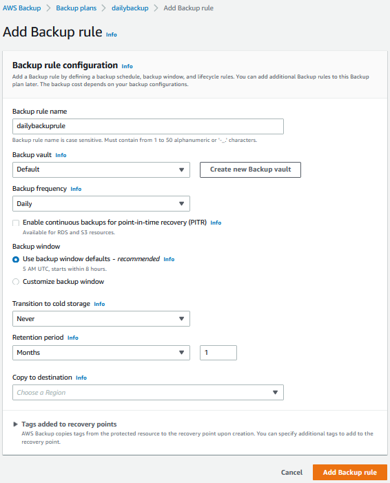
Pattern 1: Augment mainframe data retention with backup and archival on AWS

Mainframes process and generate the most business-critical data. It’s imperative to provide data protection via solutions, such as data backup, archiving, and disaster recovery. Mainframes usually use automated tape libraries—virtual tape libraries for backup and archive. These tapes need to be stored, organized, and transported to vaults and disaster recovery sites. All this can be very expensive and rigid.

There is a more cost-effective approach that helps simplify the operations of tape libraries:  leverage AWS partner tools, such as Model9, to transparently migrate the data on tape storage to AWS.

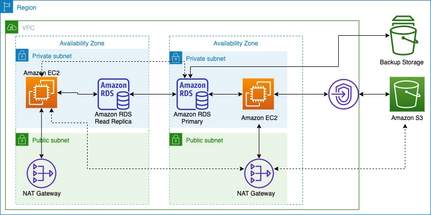
As depicted in Figure 1, mainframe data can be transferred via the secured network connection using AWS Transfer Family services or AWS DataSync to AWS cloud storage services, such as Amazon Elastic File System, Amazon Elastic Block Store, and Amazon Simple Storage Service (S3). After data is stored in AWS cloud, you can configure and move data among these services to meet with the business data processing need. Depending on data storage requirements, data storage costs can be further optimized by configuring S3 Lifecyle policies to move data among Amazon S3 storage classes. For long-term data archiving purpose, you can choose S3 Glacier storage class to achieve durability, resilience, and the optimal cost effectiveness.

Mainframe data backup and archival augmentation

Figure 1. Mainframe data backup and archival augmentation

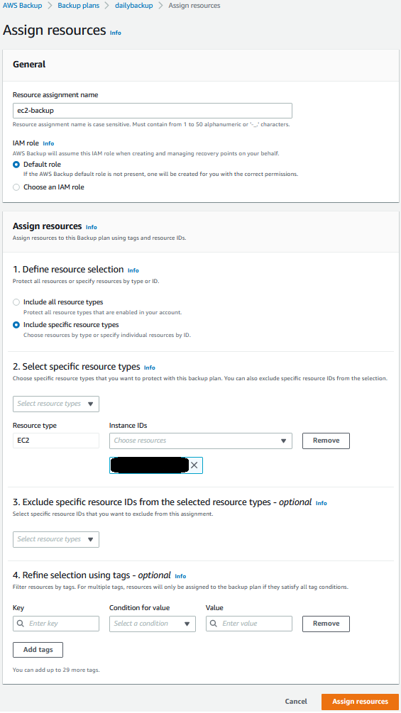
Pattern 2: Augment mainframe with agile development and test environments including CI/CD pipeline on AWS

For any business-critical business application, a typical mainframe workload requires development and test environments to support production workloads. It’s common to see the lengthy application development lifecycle, a lack of automated testing, and an absent CI/CD pipeline with most of mainframes. Furthermore, the existing mainframe development processes and tools are outdated, as they are unable to keep up with the business pace, resulting in a growing backlog. Organizations with mainframes look for application development solutions to solve these challenges.

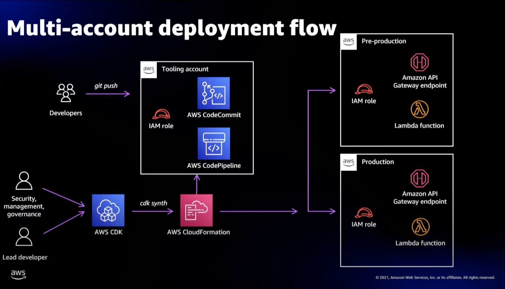
As demonstrated in Figure 2, AWS developer tools orchestrate code compilation, testing, and deployment among mainframe test environments. Mainframe test environments are either provided by the mainframe vendors as emulators or by AWS partners, such as Micro Focus. You can load the preferred developer tools and run an integrated development environment (IDE) from Amazon WorkSpaces or Amazon AppStream 2.0. Developers create or modify code in the IDE, and then commit and push their code to AWS CodeCommit. As soon as the code is pushed, an event is generated and triggers the pipeline in AWS CodePipeline to build the new code in a compilation environment via AWS CodeBuild. The pipeline pushes the new code to the test environment.

To optimize cost, you can scale the test environment capacity to meet needs. The tests are executed, and the test environment can be shut down when not in use. When the tests are successful, the pipeline pushes the code back to the mainframe via AWS CodeDeploy and an intermediary server. On the mainframe side, the code can go through a recompilation and final testing before being pushed to production.

You can further optimize operations and licensing cost of mainframe emulator by leveraging the managed integrated development and test environment provided by AWS Mainframe Modernization service.

Mainframe CI/CD augmentation

Figure 2. Mainframe CI/CD augmentation

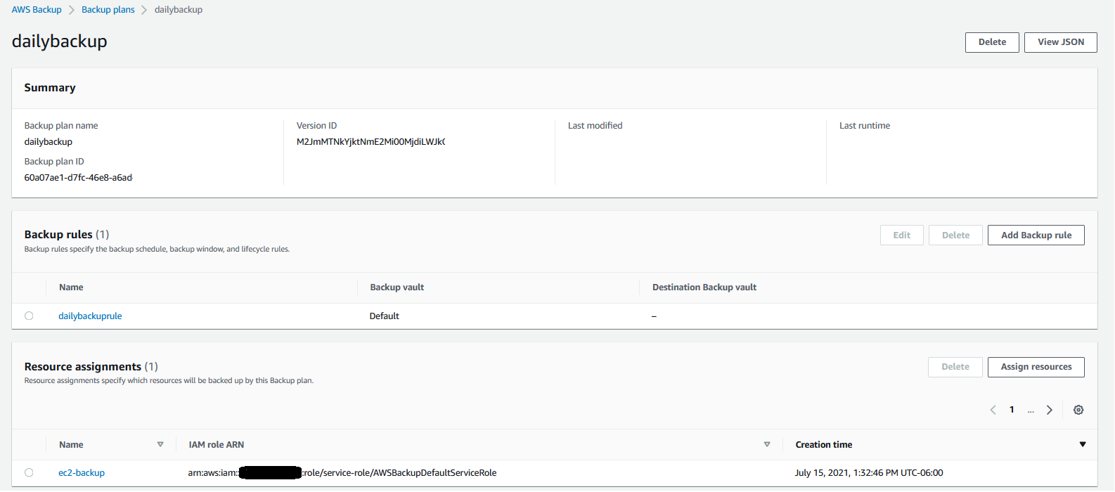
Pattern 3: Augment mainframe with agile data analytics on AWS

Core business applications running on mainframes generate a lot of data throughout the years. Decades of historical business transactions and massive amounts of user data present an opportunity to develop deep business insight. By creating a data lake using the AWS big data services, you can gain faster analytics capabilities and better insight into core business data originated from mainframe applications.

Figure 3 depicts data being pulled from relational, hierarchical, or mainframe file-based data stores on mainframes. These data are presented in various formats and stored as DB2 for z/OS, VSAM, IMS DB, IDMS, DMS, or other formats. You can use AWS partners data replication and change data capture tools from AWS Marketplace or AWS cloud services, such as Amazon Managed Streaming for Apache Kafka for near real-time data streaming, Transfer Family services, and DataSync for moving data in batch from mainframes to AWS.

Once data are replicated to AWS, you can further process data using the services like AWS Lambda, or Amazon Elastic Container Service and store the processed data on various AWS storage services, such as Amazon DynamoDB, Amazon Relational Database Service, and Amazon S3.

By using AWS big data and data analytics services, such as Amazon EMR, Amazon Redshift, Amazon Athena, AWS Glue, and Amazon QuickSight, you can develop deep business insight and present flexible visuals to your customers. Read more about mainframe data integration.

Mainframe data analytics augmentation

Figure 3. Mainframe data analytics augmentation

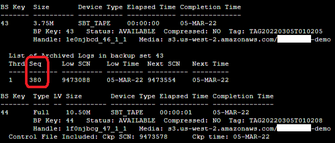
Pattern 4: Augment mainframe with new functions and channels on AWS

Organizations with a mainframe use AWS to innovate and iterate quickly, as they often lack agility. For example, a common scenario for a bank could be providing a mobile application for customer engagements, such as supporting a marketing campaign for a new credit card.

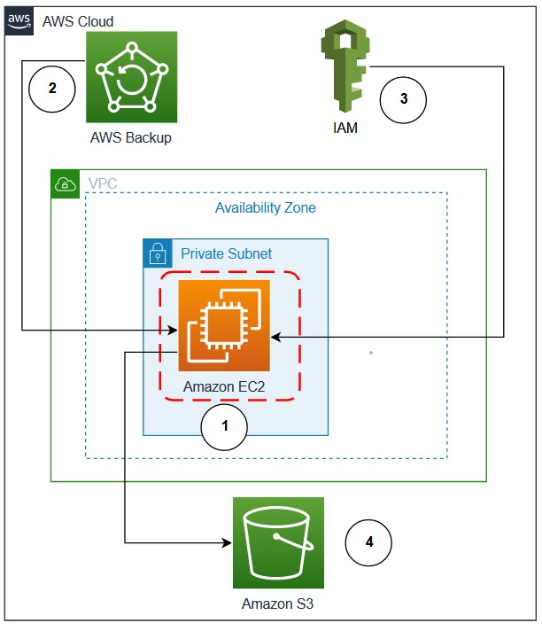
As depicted in Figure 4, with the data replicated from mainframes to AWS cloud and analyzed by AWS big data and analytics services, new business functions can be developed on cloud-native applications by using Amazon API Gateway, AWS Lambda, and AWS Fargate. These new business applications can interact with mainframe data, and the combination can give deep business insight.

To add new innovation capabilities, with time-series data generated by the new business function applications, using Amazon Forecast can predict domain-specific metrics, such as inventory, workforce, web traffic, and finances. Amazon Lex can build virtual agents, automate informational response to customer enquiries, and improve business productivity. Adding Amazon SageMaker, you can prepare data gathered from mainframe and new business applications at scale to build, train, and deploy machine learning models for any business cases.

You can further improve customer engagement by incorporating Amazon Connect and Amazon Pinpoint to build multichannel communications.

Mainframe new functions and channels augmentation

Figure 4. Mainframe new functions and channels augmentation

Conclusion

To increase agility, maximize the value of investments, and innovate faster, organizations can adopt the patterns discussed in this post to augment mainframes by using AWS services to build resilient data protection solution, provision agile CI/CD integrated development and test environment, liberate mainframe data and developing innovation solutions for new digital customer experience. With AWS Mainframe Modernization service, you can accelerate this journey and innovate faster.

Journey to Cloud-Native Architecture Series #6: Improve cost visibility and re-architect for cost optimization

Post Syndicated from Anuj Gupta original https://aws.amazon.com/blogs/architecture/journey-to-cloud-native-architecture-series-6-improve-cost-visibility-and-re-architect-for-cost-optimization/

After we improved our security posture in the 5th blog of the series, we discovered that operational costs are growing disproportionately higher than revenue. This is because the number of users grew more than 10 times on our e-commerce platform.

To address this, we created a plan to better understand our AWS spend and identify cost savings. In this post, Part 6, we’ll show you how we improved cost visibility, rearchitected for cost optimization, and applied cost control measures to encourage innovation while ensuring improved return on investment.

Identifying areas to improve costs with Cost Explorer

Using AWS Cost Explorer, we identified the following areas for improvement:

  • Improve cost visibility and establish FinOps culture:
    • Provide visibility and cost insights for untagged resources
    • Provide cost visibility into shared AWS resources
    • Better understand gross margin
  • Use Service Control Policies (SCPs) for cost control
  • Optimize costs for data transfer
  • Reduce storage costs:
  • Optimize compute costs:
    • Adjust idle resources and under-utilized resources
    • Migrate to latest generation Graviton2 instances

The following sections provide more information on the methods we used to improve these areas.

Improve cost visibility and establish FinOps culture

Provide visibility and cost insights for untagged resources

To improve our organization’s FinOps culture and help teams better understand their costs, we needed a tool to provide visibility into untagged resources and enable engineering teams to take actions on cost optimization.

We used CloudZero to automate the categorization of our spend across all AWS accounts and provide our teams the ability to see cost insights. It imports metadata from AWS resources along with AWS tags, which makes it easier to allocate cost to different categories.

Provide cost visibility into shared AWS resources

We created Dimensions such as Development, Test, and Production in CloudZero to easily group cost by environment. We also defined rules in CostFormation to help us understand the cost of running a new feature by splitting cost using rules.

Understand gross margin

To better understand how our AWS bills going up is related to delivering more value for our customers, we used the guidance in Unit Metric – The Touchstone of your IT Planning and Evaluation to identify a demand driver (in our case, number of orders). By evaluating the number of orders against AWS spend, we gained valuable insights into cost KPIs, such as cost per order, which helped us better understand gross margin for our business.

Use Service Control Policies for cost control

Following the guidance in the Control developer account costs with AWS budgets blog post, we applied SCPs to control costs and control which AWS services, resources, and individual API actions users and roles in each member account of an OU can access.

As shown in Figure 1, we applied the following cost control SCPs:

  • SCP-3 on Sandbox OU prevents modification of billing settings and limits the allowable EC2 instance types to only general purpose instances up to 4xl.
  • SCP-2 on Workload SDLC OU denies access to EC2 instances larger than 4xl. AWS Budgets sends alerts to a Slack channel when spend reaches beyond a defined threshold.
  • SCP-1 on Workload PROD OU denies access to any operations outside of the specified AWS Regions and prevents member accounts from leaving the organization.
Figure 1. Applying SCPs on different environments for cost control

Figure 1. Applying SCPs on different environments for cost control

Optimize costs for data transfer

Data transfer represented one major category of overall AWS cost in our Cost Explorer report, so we used CloudZero’s Networking Sub-category Dimension to get insights into AWS outbound, Intra-Region (Availability Zone (AZ) to AZ), NAT gateway, and S3 outbound costs.

To get more insights, we also set up a temporary Data Transfer dashboard with Amazon QuickSight using the guidance in the AWS Well-Architected Cost Optimization lab. It showed us PublicIP charges for applications, NAT gateway charges for traffic between Amazon EC2 and Amazon S3 within the same Region, inter-AZ data transfer for Development and Test environments, and cross AZ data transfer for NAT gateway.

Figure 2 shows how we used Amazon S3 Gateway endpoints (continuous line) instead of an S3 public endpoint (dotted line) to reduce NAT gateway charges. For our Development and Test environments, we created application-database partitions to reduce inter-AZ data transfer.

Data transfer charges across AZs and AWS services

Figure 2. Data transfer charges across AZs and AWS services

Reduce storage costs

Update objects to use cost appropriate S3 storage class

In our review of the Cost Explorer report, we noticed that all objects were stored using the Standard storage class in Amazon S3. To update this, we used guidance from the Amazon S3 cost optimization for predictable and dynamic access patterns blog post to identify predictable data access patterns using Amazon S3 Storage Lens.

The number of GET requests, download bytes, and retrieval rate for Amazon S3 prefixes informed us how often datasets are accessed over a period of time and when a dataset is infrequently accessed. 40% of our objects on Amazon S3 have a dynamic data access pattern. Storing this data in S3 Standard-Infrequent Access could lead to unnecessary retrieval fees, so we transitioned dynamic data access pattern objects to Amazon S3 Intelligent-Tiering and updated applications to select S3 Intelligent-Tier when uploading such objects. For infrequently accessed objects, we created Amazon S3 lifecycle policies to automatically transition objects to Amazon S3 Standard-Infrequent Access, Amazon S3 One Zone-Infrequent Access, and/or Amazon S3 Glacier storage classes.

Adopt Amazon EBS gp3

Using guidance from a re:Invent talk on Optimizing resource efficiency with AWS Compute Optimizer, we identified EBS volumes that were over-provisioned by more than 30%. AWS Compute Optimizer automatically analyzed utilization patterns and metrics such as VolumeReadBytes VolumeWriteBytes, VolumeReadOps, and VolumeWriteOps for all EBS volumes in our AWS account to provide recommendations on migrating from gp2 to gp3 volumes.

The migrate your Amazon EBS volumes from gp2 to gp3 blog post helped us identify baseline throughput and IOPS requirements for our workload, calculate cost savings using the cost savings calculator, and provided steps to migrate to gp3.

Optimize compute costs

Adjust idle resources and under-utilized resources

Deploying Instance Scheduler on AWS helped us further cost optimize Amazon EC2 and Amazon Relational Database Service (Amazon RDS) resources in Development, Test, and Pre-production environments. This way, we only pay for the 40-60 hours per week instead of the full 168 hours in a week, providing 64-76% cost savings.

Migrate to latest generation Graviton2 instances

As user traffic grew, application throughput requirements changed significantly, which led to more compute cost. We migrated to the newest generation of Graviton2 instances with similar memory and CPU, achieving higher performance for reduced cost. We updated Amazon RDS on Graviton 2Amazon ElasticCache to Graviton2, and Amazon OpenSearch on Graviton2 for low-effort cost savings. The following table shows the comparison in cost after we migrated to Graviton instances.

Service Previous Instance Cost for on-demand (per hour) in us-east-1 New Instance Cost for on-demand (per hour) in us-east-1 Cost Savings
Amazon RDS (PostgreSQL) r5.4xlarge 1.008 r6g.4xlarge 0.8064 20.00%
Amazon ElasticCache cache.r5.2xlarge 0.862 cache.r6g.xlarge 0.411 52.32%
Amazon OpenSearch (data nodes) r5.xlarge.search 0.372 r6g.xlarge.search 0.335 9.95%

After that, we tested our Java-based applications to run on an arm64 processor using the guidance on the Graviton GitHub and AWS Graviton2 for Independent Software Vendors whitepaper. We conducted functional and non-functional tests on the application to ensure that it provides the same experience for users with improved performance.

Load testing for cost optimization

We included load testing in CI/CD pipeline to avoid over-provisioning and to identify resource bottlenecks before our application goes into production. To do this, we used Serverless Artillery workshop to set up a load testing environment in a separate AWS account. As a part of that load testing, we were able to simulate production traffic at required scale with much reduced cost than using EC2 instances.

Conclusion

In this blog post, we discussed how observations in Cost Explorer helped us identify improvements for cost management and optimization. We talked about how you get better cost visibility using CloudZero and apply cost control measures using SCPs. We also talked about how you can save data transfer cost, storage cost and compute cost with low effort.

Other blogs in this series

Save time and effort in assessing your teams’ architectures with pattern-based architecture reviews

Post Syndicated from Rostislav Markov original https://aws.amazon.com/blogs/architecture/save-time-and-effort-in-assessing-your-teams-architectures-with-pattern-based-architecture-reviews/

Enterprise architecture frameworks use architecture reviews as a key governance mechanism to review and approve architecture designs, identify quality enhancements, and align architectural decisions with enterprise-wide standards. Architecture reviews are very thorough, but it typically takes a lot of time and teamwork to prepare for them, which means developers can’t always move as quickly as they’d like.

If your team needs a flexible, faster option to review their architecture, consider adopting pattern-based architecture reviews (PBARs). PBARs may not find every issue that a traditional architecture review will. However, in situations where you need to accommodate tight deadlines or budgets, changing project requirements, or multiple releases, they offer a simpler, quicker, more focused way to address issues and ensure your architecture aligns with business needs.

Pattern-based architecture reviews vs. traditional architecture reviews

PBARs use generic architecture patterns (in other words, generalized, reusable solutions to common design problems) to review non-functional system properties and align architectural patterns to business outcomes.

Traditional architecture reviews
Pattern-based architecture reviews
Consider system architecture as a highly stable documentation of all functional and system needs and their implementation plan

  • Require detailed architecture documentation
  • Review functional requirements, infrastructure configuration, and process specifications
  • Focus on technical configuration completeness
  • Are used to sign off on architectural decisions and/or authorize the implementation plan
Adopt a continuous architecture mindset that focuses on enhancing system composition and quality attributes

  • Use generalized solutions with existing architectural documentation
  • Focus on identifying design inconsistencies and opportunities to improve on required system capabilities and quality attributes via architectural patterns
  • Increase developer productivity and identify opportunities to shorten the implementation plan through component re-use

PBARs are broadly applicable to any cloud initiative, ranging from migration use cases to complex large-scale development initiatives. Here are just a few examples of ways to use them:

  • With cloud migrations, PBARs help manage various infrastructure and integration patterns, including like-for-like moves and full refactoring options.
  • A few infrastructure patterns, such as N-tier architecture, are applicable to many applications. After the pilot phase, these cloud infrastructure patterns serve as reusable blueprints for follow-on migrations, which reduces the amount of repetitive work and ensures compliance with security controls.
  • With new development use cases, PBARs emphasize composition through reusable code
  • Teams with novel uses are encouraged to verify the new pattern through early prototyping as opposed to heavy documentation and requirements analysis.

Use case: Applying PBARs across multiple teams to meet stringent go-live date

We introduced PBARs to a global industrial company’s large cloud development initiative where developers had no prior AWS experience and their go-live date was in six months. The initiative spanned over 50 development teams along 10 functional domains and 11 geographical locations from Americas to Asia. Each team was responsible for developing between one and six customer-facing aggregated services exposed via APIs (asset management, tenant billing, customer onboarding, or event analytics).

Socialize initial design patterns

To get the team to use PBARs, we advocated to adopt particular managed/serverless services to reduce management overhead, as shown in Figure 1.

Proposed AWS services for use by development teams

Figure 1. Proposed AWS services for use by development teams

We also shared an initial set of design patterns, including:

Containerized and serverless design patterns

Figure 2. Containerized and serverless design patterns

Shorten review times by applying lessons learned from early adopters

PBARs were run by domain architects, team architects, lead engineers, and product owners. We also invited teams with similar use cases and system requirements for joint reviews.

They brought knowledge and experience that allowed the process to conclude within two weeks for all teams with minimal preparation—significantly faster than traditional reviews.

Complete reviews quicker and increase participation and understanding by focusing the review

Because PBARs move quickly, we had to be specific about the areas we chose to focus on improving or evaluating. We worked towards identifying inconsistencies between system requirements and pattern selection, any special needs, and opportunities to improve on non-functional requirements, including:

  • Security
  • Availability and operations
  • Deployment process
  • Speed and reproducibility
  • Quality concerns and defects

In narrowing the PBAR’s scope, we were also able to complete the architecture reviews more quickly and increase participants’ understanding of the architecture and critical project needs.

Findings

Our technical findings showed single points of failure, service scalability limits, or opportunities to automate test/deployment/recovery processes.

The PBARs emphasized pattern reuse and, therefore, standardization in the early development phase. This required follow-on tailoring to individual use cases, such as distinguishing data ingest profiles by data type and throughput or moving from containerized deployments for data analytics jobs to AWS Lambda and Amazon Athena.

PBARs also provided actionable feedback on what to address prior to the go-live date.

  • By emphasizing non-functional aspects, our PBARs helped create a case for zero-defect culture where fixing bugs had priority over new features.
  • Early-adopter teams of architectural patterns served as internal champions, providing informal support to others on how to address review findings.
  • Follow-on game days and performance load tests helped teams gain first-hand exposure to PBAR findings in simulated environments.

Introducing pattern-based architecture reviews in your organization

In large enterprises, PBARs serve as a demand intake mechanism for their cloud center of excellence (CoE). They facilitate adoption of established pattern solutions and contribute new use cases to the enterprise-wide roadmap of cloud architectural patterns.

Three organizational disciplines contribute to PBARs:

  1. Application teams envision system capabilities and outcomes and own decision-making on application design and operations.
  2. The enterprise architecture team oversee the adoption of architectural best practices and work closely with application teams and the cloud CoE to review architectural patterns.
  3. The cloud CoE approves and publishes pattern solutions and tracks their adoption in the cloud service catalog. At AWS, we use AWS Service Catalog portfolios to publish pattern solutions to developers.

Figure 3 describes the high-level process tasks and responsibilities:

  • Application teams solicit PBAR with enterprise architects who help identify and customize suitable design patterns for particular use cases.
  • If the use case requires novel pattern, architects work with the application team on early prototyping and approval of the novel system architecture. They also work with the cloud CoE team to generalize and publish novel pattern solutions in the service catalog of the cloud CoE.

To better align with agile development cycles, we recommend establishing internal commitments on the time to schedule and conduct PBARs as well as auto-approval options for teams re-using existing pattern solutions, in order to allow developers to move as quickly as possible.

Figure 1. PBAR workflow

Figure 3. PBAR workflow

PBARs provide lightweight architectural governance across enterprises. They help focus your teams on non-functional system properties and align architectural patterns to business outcomes.

As shown in our use case, PBARs enable teams to build faster and help change the perception of enterprise-wide architecture reviews as a corporate guardrail. For teams with novel use cases, PBARs encourage pattern validation through early prototyping and therefore provide modern alternative for agile cloud projects.

If you are looking to scale your cloud architecture governance effectively, consider adopting PBARs.

Related information

Use the following links to learn more about patterns you can use on your next architecture review:

Implementing the AWS Well-Architected Custom Lens lifecycle in your organization

Post Syndicated from Robert Hoffman original https://aws.amazon.com/blogs/architecture/implementing-the-aws-well-architected-custom-lens-lifecycle-in-your-organization/

In this blog post, we present a lifecycle that helps you build, validate, and improve your own AWS Well-Architected Custom Lens, in order to roll it out across your whole organization. The AWS Well-Architected Custom Lens is a new feature of the AWS Well-Architected Tool that lets you bring your own best practices to complement the existing Well-Architected Framework.

The Custom Lens lifecycle: how a Custom Lens can benefit your organization

The AWS Well-Architected Custom Lens Lifecycle

Figure 1. The AWS Well-Architected Custom Lens lifecycle

Each organization has its own requirements, processes, best practices, and tools, but the information can be spread over many systems and knowledge bases. A Custom Lens can capture the specifics of a working environment and let coworkers access this information in a single place—from the AWS console—without the need to go to a separate tool. A Custom Lens can be created in a central management account and securely shared with other accounts.

A Custom Lens can be updated periodically as either a major or minor version. If it is a minor version, the change is automatically applied to all accounts that the lens has been shared with. If it is a major version, the user has to accept the updated Custom Lens and a summary of the changes is displayed to the user. Accepting the changes then applies the update for existing workload reviews, and prompts the user to review the workload. Thus, updating a Custom Lens is an effective mechanism to continuously inform teams about new best practices.

In addition, maintaining and improving a Custom Lens continuously helps to identify gaps in organization-wide tooling, guidance, or documentation. You can aggregate feedback and metrics from reviews that have been performed and use it to drive the improvement process of the content. More importantly, the gathered metrics help measure the overall adherence to best practices and requirements in your organization. If you focus on creating clear, concise, and actionable content for your Custom Lens, the time needed to identify and implement improvements is reduced. As teams realize the value of the Custom Lens, more reviews will be performed, and you will receive more data to construct a comprehensive view.

1. Plan

The Plan phase identifies the benefits that a Custom Lens can provide your organization by identifying current gaps. You also define the scope of your Custom Lens, which is the type of content that supports your desired business outcomes. Depending on the scope, you need to identify the appropriate stakeholders and gain support for the initiative.

2. Implement

In the Implement phase, content is created for the Custom Lens with a working group. While doing this, you can identify missing supplementary artefacts, like documentation or tooling. If that is the case, you can create these artefacts and link to them from the Custom Lens Improvement Plan.

As part of the implementation, the Custom Lens is created by uploading a JSON file in the appropriate format to a central management account, then, sharing the lens with the organization’s AWS accounts. You can share the Custom Lens with IAM Principals, such as users, roles, and AWS accounts. For broader and more efficient sharing, you now have the ability to scale by sharing your Custom Lens with individual organizational units or the entire AWS Organizations. This feature reduces management overhead and removes the need for a custom automation.

3. Measure

The Measure phase aggregates feedback and metrics from reviews that have been performed with your Custom Lens; this information is used to drive the improvement process.

The Well-Architected Tool offers a way to share workload reviews, and you can use this to share all reviews with a central AWS account. You can then analyze the reviews in the central account by extracting the data and analyzing it, for example, by building a dashboard. The Well-Architected Lab for building custom reports provides a solution that can be implemented.

4. Improve

In the Improve phase, the gathered metrics and feedback are used to identify areas for future improvement. For example, you might find common gaps among the performed workload reviews, where the same best practices are not fulfilled. When you investigate the root cause, you can learn that the existing content lacks clarity or that the suggested tools are difficult to use.

In addition, improvements, such as content gaps that were not addressed during the first iteration of the Custom Lens, can be added to the backlog before you repeat the cycle.

To roll out changes of your Custom Lens in an automated and repeatable fashion, you can implement the architecture depicted in Figure 2.

Combining AWS CodeCommit with AWS Lambda to update your Custom Lens whenever a file change is pushed to the code repository

Figure 2. Combining AWS CodeCommit with AWS Lambda to update your Custom Lens whenever a file change is pushed to the code repository

This architecture enables automated releases of new versions of your Custom Lens whenever you commit an updated JSON file to the code repository. In detail, the steps are:

  1. The JSON file of your Custom Lens is stored in an AWS CodeCommit repository. An author pushes an updated version of the file to the repository.
  2. The CodeCommit repository is configured with a trigger action that invokes an AWS Lambda function on each commit.
  3. The Lambda function downloads the updated file by using the GetFile API of CodeCommit. Then, the Lambda function imports the updated Custom Lens and publishes it as a new version by using ImportLens and CreateLensVersion APIs of the AWS Well-Architected Tool, then shares the Custom Lens using CreateLensShare.
  4. The updated Custom Lens is available in all accounts that the lens has been shared with.
  5. Reviewers can create new workload reviews with the Custom Lens or upgrade to the newest version for existing workload reviews.

Conclusion

In this blog post, we walked you through the Custom Lens lifecycle, a process to create and continuously improve a Custom Lens for your organization. If you have a special software development lifecycle, a customized security and compliance framework, or other highly specific requirements or best practices that you want disseminated and measurable, learn more about how to create a Custom Lens in the Well-Architected Tool.

AWS Well-Architected is a set of guiding design principles developed by AWS to help organizations build secure, high-performing, resilient, and efficient infrastructure for a variety of applications and workloads. Use the AWS Well-Architected Tool to review your workloads periodically to address important design considerations and ensure that they follow the best practices and guidance of the AWS Well-Architected Framework. For follow up questions or comments, join our growing community on AWS re:Post.

Let’s Architect! Architecting for DevOps

Post Syndicated from Luca Mezzalira original https://aws.amazon.com/blogs/architecture/lets-architect-architecting-for-devops/

Under a DevOps model, the development and operations teams work together and share their skills and knowledge. Sometimes, these teams are merged into a single team where the engineers work across the entire application lifecycle, from development to deployment.

The objective of DevOps is to deliver applications and services quickly and efficiently. This faster pace allows companies to better adapt to their customers’ needs and changes in the market.

In this edition of Let’s Architect!, we’ll talk about DevOps culture and share content to provide helpful mental models and strategies for your work as an architect or engineer.

Automating cross-account CI/CD pipelines

Companies often use the cloud to run their microservices. This means they’re working with different AWS accounts and hosting each microservice in a dedicated account.

This method can be helpful to isolate different environments for software deployment pipelines. A well-designed pipeline is fundamental to releasing software quickly because it allows DevOps engineers to automate the software deployment process.

This video shows the mindset to adopt while designing pipelines for deploying resources across different environments. You’ll learn how to design a pipeline, how to build it using AWS CDK, and see how everything looks in the AWS Console.

AWS X-Ray helps developers analyze distributed applications, such as those built using a microservices architecture

AWS X-Ray helps developers analyze distributed applications, such as those built using a microservices architecture

Automating safe, hands-off deployments

Amazon adopted continuous delivery across the company as a way to automate and standardize how software is deployed and to reduce the time it takes for changes to reach production. In this system, improvements to the release process build up over time. Once deployment risks are identified, teams iterate on the release process and add extra safety in the automated pipeline.

A typical continuous delivery pipeline has four major phases—source, build, test, and production (prod). This article describes the mental models and approaches that engineer use at Amazon to help you understand the design considerations for each step of the pipeline and learn some recommended practices.

Each pipeline has these four major steps; however, more granularity is often added in the testing stage to take advantage of multiple pre-production environments

Each pipeline has these four major steps; however, more granularity is often added in the testing stage to take advantage of multiple pre-production environments

Covert ops on DevOps: Leveraging security to shift left

Architects often deal with complexity and ambiguity while designing architectures and interacting with stakeholders. Consequently, their architectures evolve and grow in complexity.

When your workload becomes more complex, security is an important area to consider and requires attention during the entire Software Development Life Cycle (SDLC). This video shows some methods to add security in a DevOps culture. You’ll learn about shifting your security left to create collaborations between developers and the security team. It will also show you how to uncover vulnerabilities in the SDLC as well as the strategies to implement and automate security in the process through a security as code mindset.

At a high level, people build applications with source code, version control, CI/CD, registries and deployments, and during each step we should design to prevent specific vulnerabilities

At a high level, people build applications with source code, version control, CI/CD, registries and deployments, and during each step we should design to prevent specific vulnerabilities

Instrumenting distributed systems for operational visibility

Every member of a development team works like an owner and operator of the service, whether that member is a developer, manager, or another role. Software developers and architects usually work with logs to see the status of their systems. Logs act as the mechanism to share what’s happening in the software that is running. This information is used for troubleshooting and performance improvement.

This article describes some approaches to feed data into operational dashboards to measure real-time metrics, invoke alarms, and engage with operators to diagnose problems. You’ll learn some mental models and best practices to design a logging system through a set of stories, considerations, and common examples with code samples.

AWS X-Ray helps developers analyze distributed applications, such as those built using a microservices architecture

AWS X-Ray helps developers analyze distributed applications, such as those built using a microservices architecture

Related information

If you want to learn more about DevOps, check What is DevOps?, a public resource with plenty of examples and introductory articles.

See you next time!

Thanks for reading! See you in a couple of weeks when we discuss strategies for applying the AWS Well-Architected framework to your workloads.

Other posts in this series

Looking for more architecture content?

AWS Architecture Center provides reference architecture diagrams, vetted architecture solutions, Well-Architected best practices, patterns, icons, and more!

Using AWS Backup and Oracle RMAN for backup/restore of Oracle databases on Amazon EC2: Part 2

Post Syndicated from Jeevan Shetty original https://aws.amazon.com/blogs/architecture/using-aws-backup-and-oracle-rman-for-backup-restore-of-oracle-databases-on-amazon-ec2-part-2/

Customers running Oracle databases on Amazon Elastic Compute Cloud (Amazon EC2) often take database and schema backups using Oracle native tools like Data Pump and Recovery Manager (RMAN) to satisfy data protection, disaster recovery (DR), and compliance requirements. A priority is to reduce backup time as the data grows exponentially and recover sooner in case of failure/disaster.

In Part 1 of this two-part series, we explain how we can use AWS Backup and Amazon Simple Storage Service (Amazon S3) bucket to perform the backup and restore of an Oracle Database on AWS EC2.

In Part 2, we provide a mechanism to use AWS Backup to create a full backup of the EC2 instance, including the OS image, Oracle binaries, logs, and data files. The mechanism also uses Oracle RMAN to perform archived redo log backup to Amazon Elastic File System (Amazon EFS). Then, we demonstrate the steps to restore a database to a specific point-in-time using AWS Backup and Oracle RMAN.

Solution overview

Figure 1 demonstrates the workflow:

  1. Oracle database on Amazon EC2 configured with Oracle Secure Backup.
  2. AWS Backup service to backup EC2 instance at regular intervals.
  3. Amazon EFS for storing Oracle RMAN archive log backups.
Oracle Database in Amazon EC2 using AWS Backup and EFS for backup and restore

Figure 1. Oracle Database in Amazon EC2 using AWS Backup and EFS for backup and restore

Prerequisites

  1. An AWS account
  2. Oracle database and AWS CLI in an EC2 instance
  3. Access to configure AWS Backup
  4. Access to configure EFS to store the Oracle RMAN archive log backups

1. Configure AWS Backup

Configure AWS Backup as detailed in Step 1 of Part 1.

Oracle RMAN archive log backup

While AWS Backup is now creating a daily backup of the EC2 instance, we also want to make sure we backup the archived log files to a protected location. This will let us do point-in-time restores and restore to more recent times than just the last daily EC2 backup. Below we provide the steps to backup archive log using RMAN to Amazon EFS.

Backup/restore archive logs to/from Amazon EFS

Backing up the Oracle Archive logs is an important part of the process. In this section, we will describe how you can backup their Oracle archive logs to Amazon EFS. One advantage of this option (as compared with using Oracle Secure Backup [detailed in Part 1 of this series]) is that it does not require any additional Oracle licensing.

2. Configure Amazon EFS

a. Create an Amazon EFS file system that will be used to store Oracle RMAN Archive log backups. The image below details the steps involved in creation of an Amazon EFS. Consider that a sample file system ID: fs-0123abcdef012345 is created and will be used to store RMAN archive log backup.

Figure 2. Configure Amazon EFS which is used to store Oracle RMAN archive log backups

b. Install the Amazon EFS Client and follow instructions to install EFS client on RHEL EC2 instance. Note: next steps were tested on RHEL 7.9.

sudo yum -y install git
sudo yum -y install rpm-build
git clone https://github.com/aws/efs-utils
cd efs-utils/
sudo yum -y install make
sudo make rpm
sudo yum -y install ./build/amazon-efs-utils*rpm

c. Mount the EFS file system on your EC2 instance. In this example, we show the steps to mount EFS filesystem on EC2 Instance (if the command requests to upgrade stunnel, refer to Upgrading stunnel. Ensure that the EC2 instance profile attached has necessary policies to access EFS. /rman for mount point and file system ID: fs-0123abcdef012345 are examples for EFS file system.

sudo mkdir /rman
sudo mount -t efs -o tls,iam fs-0123abcdef012345 /rman

d. To mount EFS file system automatically on EC2 instance reboot, add an entry in /etc/fstab. This example is for RHEL EC2 instance:

fs-0123abcdef012345:/      /rman        efs     _netdev,tls,iam        0 0

3. Configure RMAN backup to Amazon EFS

With Amazon EFS mounted on EC2 instance, we can configure Oracle RMAN archive log backups to EFS. In below commands oratst is used as an example of your ORACLE_SID.

a. Configure RMAN repository to take control file backup to Amazon EFS automatically.

CONFIGURE CONTROLFILE AUTOBACKUP FORMAT FOR DEVICE TYPE DISK TO '/rman/ctrl-D_%d_%F';
CONFIGURE CONTROLFILE AUTOBACKUP ON;

b. Create a script (for example, rman_archive.sh) with below commands and schedule using crontab (example entry: */5 * * * * rman_archive.sh) to run every 5 minutes. This will ensure that Oracle Archive logs are backed up to Amazon EFS (/rman) frequently, ensuring an recovery point objective (RPO) of 5 minutes.

dt=`date +%Y%m%d_%H%M%S`

rman target / log=/rman/rman_arch_bkup_oratst_${dt}.log <<EOF

RUN
{
    allocate channel c1_efs device type disk format '/rman/arch-D-%d_%T_s%s_p%p' MAXPIECESIZE 10G;
    BACKUP ARCHIVELOG ALL delete all input;
    release channel c1_efs;
}

EOF

4. Perform database point-in-time recovery

In event of a database crash/corruption, we can use AWS Backup service and Oracle RMAN archive log backup to recover database to a specific point-in-time.

a. Typically, you would pick the most recent Recovery Point completed before the time to which you wish to recover. Using AWS Backup, identify the Recovery point ID to restore by following the steps from Restoring an Amazon EC2 instance. Note: when following the steps, be sure to set the “User data” settings as described in the next bulleted item.

After the EBS volumes are created from the snapshot, there is no need to wait for all of the data to transfer from Amazon S3 to your Amazon EBS volume before your attached instance can start accessing the volume. Amazon EBS Snapshots implement lazy loading, so that you can begin using them right away.

b. Ensure that database does not start automatically after restoring the EC2 instance, by renaming /etc/oratab. Use below command in “User data” section while restoring EC2 instance. After database recovery, we can rename it back to /etc/oratab.

#!/usr/bin/sh
sudo su - 
mv /etc/oratab /etc/oratab_bk

c. Login to the EC2 instance once it is up and execute the RMAN recovery commands mentioned below. Identify the DBID from RMAN logs saved in the EFS. Below commands use database oratst as an example.

rman target /

RMAN> startup nomount

RMAN> set dbid DBID


# Below command is to restore the controlfile from autobackup

RMAN> RUN
{
    set controlfile autobackup format for device type disk to '/rman/ctrl-D_%d_%F';
    RESTORE CONTROLFILE FROM AUTOBACKUP;
    alter database mount;
}


#Identify the recovery point (sequence_number) by listing the backups available in catalog.

RMAN> list backup;

In Figure 3, the most recent archive log backed up is 460, so you can use this sequence number in the next set of RMAN commands.

RMAN> RUN
{
    allocate channel c1_efs device type disk format '/rman/arch-D-%d_%T_s%s_p%p';    
    recover database until sequence sequence_number;
    ALTER DATABASE OPEN RESETLOGS;
    release channel c1_efs;
}

Sample output of Oracle RMAN “list backup” command

Figure 3. Sample output of Oracle RMAN “list backup” command

d. To avoid performance issues due to lazy loading, after the database is open, you can run below command to force a faster restoration of the blocks from S3 bucket to EBS volumes (below example allocates two channels and validates the entire database).

RMAN> RUN
{
  ALLOCATE CHANNEL c1 DEVICE TYPE DISK;
  ALLOCATE CHANNEL c2 DEVICE TYPE DISK;
  VALIDATE database section size 1200M;
}

e. This completes the recovery of database, and we can let the database to auto start by renaming file back to /etc/oratab.

mv /etc/oratab_bk /etc/oratab

5. Backup retention

Ensure that the AWS Backup Lifecycle policy match Oracle archive log backup retention. Also, follow documentation to configure Oracle backup retention and deleting expired backup. Below is a sample command for Oracle backup retention.

CONFIGURE BACKUP OPTIMIZATION ON;
CONFIGURE RETENTION POLICY TO RECOVERY WINDOW OF 31 DAYS; 

RMAN> RUN
{
    allocate channel c1_efs device type disk format '/rman/arch-D-%d_%T_s%s_p%p';

    crosscheck backup;
    delete noprompt obsolete;
    delete noprompt expired backup;
    
    release channel c1_efs;
}

Cleanup

Follow below instructions to remove or cleanup the setup:

  1. Delete the backup plan created in Step 1.
  2. Remove the cron entry from the EC2 instance configured in Step 3b.
  3. Delete the EFS that was created in Step 2 to store Oracle RMAN archive log backups.

Conclusion

In this post, we demonstrated the use for AWS Backup for EC2 snapshot and EFS as storage for Oracle RMAN archive log backups. With this strategy for backup, Oracle Database running on EC2 can be restored and recovered to a point-in-time faster than oracle native backup and recovery strategies. Also, by using EFS for Oracle RMAN archive log backups, we can avoid the additional licensing required to use Oracle Secure Backup, explained in Part 1. You can leverage this solution to facilitate restoring copies of your production database for development or testing purposes and to Recover from a user error that removes data or corrupts existing data.

To learn more about AWS Backup, refer to the AWS Backup Documentation.

Using AWS Backup and Oracle RMAN for backup/restore of Oracle databases on Amazon EC2: Part 1

Post Syndicated from Jeevan Shetty original https://aws.amazon.com/blogs/architecture/using-aws-backup-and-oracle-rman-for-backup-restore-of-oracle-databases-on-amazon-ec2-part-1/

Customers running Oracle databases on Amazon Elastic Compute Cloud (Amazon EC2) often take database and schema backups using Oracle native tools, like Data Pump and Recovery Manager (RMAN), to satisfy data protection, disaster recovery (DR), and compliance requirements. A priority is to reduce backup time as the data grows exponentially and recover sooner in case of failure/disaster.

In situations where RMAN backup is used as a DR solution, using AWS Backup to backup the file system and using RMAN to backup the archive logs are an efficient method to perform Oracle database point-in-time recovery in the event of a disaster.

Sample use cases:

  1. Quickly build a copy of production database to test bug fixes or for a tuning exercise.
  2. Recover from a user error that removes data or corrupts existing data.
  3. A complete database recovery after a media failure.

There are two options to backup the archive logs using RMAN:

  1. Using Oracle Secure Backup (OSB) and an Amazon Simple Storage Service (Amazon S3) bucket as the storage for archive logs
  2. Using Amazon Elastic File System (Amazon EFS) as the storage for archive logs

This is Part 1 of this two-part series, we provide a mechanism to use AWS Backup to create a full backup of the EC2 instance, including the OS image, Oracle binaries, logs, and data files. In this post, we will use Oracle RMAN to perform archived redo log backup to an Amazon S3 bucket. Then, we demonstrate the steps to restore a database to a specific point-in-time using AWS Backup and Oracle RMAN.

Solution overview

Figure 1 demonstrates the workflow:

  1. Oracle database on Amazon EC2 configured with Oracle Secure Backup (OSB)
  2. AWS Backup service to backup EC2 instance at regular intervals.
  3. AWS Identity and Access Management (IAM) role for EC2 instance that grants permission to write archive log backups to Amazon S3
  4. S3 bucket for storing Oracle RMAN archive log backups
Figure 1. Oracle Database in Amazon EC2 using AWS Backup and S3 for backup and restore

Figure 1. Oracle Database in Amazon EC2 using AWS Backup and S3 for backup and restore

Prerequisites

For this solution, the following prerequisites are required:

  1. An AWS account
  2. Oracle database and AWS CLI in an EC2 instance
  3. Access to configure AWS Backup
  4. Acces to S3 bucket to store the RMAN archive log backup

1. Configure AWS Backup

You can choose AWS Backup to schedule daily backups of the EC2 instance. AWS Backup efficiently stores your periodic backups using backup plans. Only the first EBS snapshot performs a full copy from Amazon Elastic Block Storage (Amazon EBS) to Amazon S3. All subsequent snapshots are incremental snapshots, copying just the changed blocks from Amazon EBS to Amazon S3, thus, reducing backup duration and storage costs. Oracle supports Storage Snapshot Optimization, which takes third-party snapshots of the database without placing the database in backup mode. By default, AWS Backup now creates crash-consistent backups of Amazon EBS volumes that are attached to an EC2 instance. Customers no longer have to stop their instance or coordinate between multiple Amazon EBS volumes attached to the same EC2 instance to ensure crash-consistency of their application state.

You can create daily scheduled backup of EC2 instances. Figures 2, 3, and 4 are sample screenshots of the backup plan, associating an EC2 instance with the backup plan.

Configure backup rule using AWS Backup

Figure 2. Configure backup rule using AWS Backup

Select EC2 instance containing Oracle Database for backup

Figure 3. Select EC2 instance containing Oracle Database for backup

Summary screen showing the backup rule and resources managed by AWS Backup

Figure 4. Summary screen showing the backup rule and resources managed by AWS Backup

Oracle RMAN archive log backup

While AWS Backup is now creating a daily backup of the EC2 instance, we also want to make sure we backup the archived log files to a protected location. This will let us do point-in-time restores and restore to other recent times than just the last daily EC2 backup. Here, we provide the steps to backup archive log using RMAN to S3 bucket.

Backup/restore archive logs to/from Amazon S3 using OSB

Backing-up the Oracle archive logs is an important part of the process. In this section, we will describe how you can backup their Oracle Archive logs to Amazon S3 using OSB. Note: OSB is a separately licensed product from Oracle Corporation, so you will need to be properly licensed for OSB if you use this approach.

2. Setup S3 bucket and IAM role

Oracle Archive log backups can be scheduled using cron script to run at regular interval (for example, every 15 minutes). These backups are stored in an S3 bucket.

a. Create an S3 bucket with lifecycle policy to transition the objects to S3 Standard-Infrequent Access.
b. Attach the following policy to the IAM Role of EC2 containing Oracle database or create an IAM role (ec2access) with the following policy and attach it to the EC2 instance. Update bucket-name with the bucket created in previous step.


        {
            "Sid": "S3BucketAccess",
            "Effect": "Allow",
            "Action": [
                "s3:PutObject",
                "s3:GetObjectAcl",
                "s3:GetObject",
                "s3:ListBucket",
                "s3:DeleteObject"
            ],
            "Resource": [
                "arn:aws:s3:::bucket-name",
                "arn:aws:s3:::bucket-name/*"
            ]
        }

3. Setup OSB

After we have configured the backup of EC2 instance using AWS Backup, we setup OSB in the EC2 instance. In these steps, we show the mechanism to configure OSB.

a. Verify hardware and software prerequisites for OSB Cloud Module.
b. Login to the EC2 instance with User ID owning the Oracle Binaries.
c. Download Amazon S3 backup installer file (osbws_install.zip)
d. Create Oracle wallet directory.

mkdir $ORACLE_HOME/dbs/osbws_wallet

e. Create a file (osbws.sh) in the EC2 instance with the following commands. Update IAM role with the one created/updated in Step 2b.

java -jar osbws_install.jar —IAMRole ec2access walletDir $ORACLE_HOME/dbs/osbws_wallet -libDir $ORACLE_HOME/lib/

f. Change permission and run the file.

chmod 700 osbws.sh
./osbws.sh

Sample output: AWS credentials are valid.
Oracle Secure Backup Web Service wallet created in directory /u01/app/oracle/product/19.3.0.0/db_1/dbs/osbws_wallet.
Oracle Secure Backup Web Service initialization file /u01/app/oracle/product/19.3.0.0/db_1/dbs/osbwsoratst.ora created.
Downloading Oracle Secure Backup Web Service Software Library from file osbws_linux64.zip.
Download complete.

g. Set ORACLE_SID by executing below command:

. oraenv

h. Running the script – osbws.sh installs OSB libraries and creates a file called osbws<ORACLE_SID>.ora.
i. Add/modify below with S3 bucket(bucket-name) and region(ex:us-west-2) created in Step 2a.

OSB_WS_HOST=http://s3.us-west-2.amazonaws.com
OSB_WS_BUCKET=bucket-name
OSB_WS_LOCATION=us-west-2

4. Configure RMAN backup to S3 bucket

With OSB installed in the EC2 instance, you can backup Oracle archive logs to S3 bucket. These backups can be used to perform database point-in-time recovery in case of database crash/corruption . oratst is used as an example in below commands.

a. Configure RMAN repository. Example below uses Oracle 19c and Oracle Sid – oratst.

RMAN> configure channel device type sbt parms='SBT_LIBRARY=/u01/app/oracle/product/19.3.0.0/db_1/lib/libosbws.so,SBT_PARMS=(OSB_WS_PFILE=/u01/app/oracle/product/19.3.0.0/db_1/dbs/osbwsoratst.ora)';

b. Create a script (for example, rman_archive.sh) with below commands, and schedule using crontab (example entry: */5 * * * * rman_archive.sh) to run every 5 minutes. This will makes sure Oracle Archive logs are backed up to Amazon S3 frequently, thus ensuring an recovery point objective (RPO) of 5 minutes.

dt=`date +%Y%m%d_%H%M%S`

rman target / log=rman_arch_bkup_oratst_${dt}.log <<EOF

RUN
{
	allocate channel c1_s3 device type sbt
	parms='SBT_LIBRARY=/u01/app/oracle/product/19.3.0.0/db_1/lib/libosbws.so,SBT_PARMS=(OSB_WS_PFILE=/u01/app/oracle/product/19.3.0.0/db_1/dbs/osbwsoratst.ora)' MAXPIECESIZE 10G;

	BACKUP ARCHIVELOG ALL delete all input;
	Backup CURRENT CONTROLFILE;

release channel c1_s3;
	
}

EOF

c. Copy RMAN logs to S3 bucket. These logs contain the database identifier (DBID) that is required when we have to restore the database using Oracle RMAN.

aws s3 cp rman_arch_bkup_oratst_${dt}.log s3://bucket-name

5. Perform database point-in-time recovery

In the event of a database crash/corruption, we can use AWS Backup service and Oracle RMAN Archive log backup to recover database to a specific point-in-time.

a. Typically, you would pick the most recent recovery point completed before the time you wish to recover. Using AWS Backup, identify the recovery point ID to restore by following the steps on restoring an Amazon EC2 instance. Note: when following the steps, be sure to set the “User data” settings as described in the next bullet item.

After the EBS volumes are created from the snapshot, there is no need to wait for all of the data to transfer from Amazon S3 to your EBS volume before your attached instance can start accessing the volume. Amazon EBS snapshots implement lazy loading, so that you can begin using them right away.

b. Be sure the database does not start automatically after restoring the EC2 instance, by renaming /etc/oratab. Use the following command in “User data” section while restoring EC2 instance. After database recovery, we can rename it back to /etc/oratab.

#!/usr/bin/sh
sudo su - 
mv /etc/oratab /etc/oratab_bk

c. Login to the EC2 instance once it is up, and execute the RMAN recovery commands mentioned. Identify the DBID from RMAN logs saved in the S3 bucket. These commands use database oratst as an example:

rman target /

RMAN> startup nomount

RMAN> set dbid DBID

# Below command is to restore the controlfile from autobackup

RMAN> RUN
{
    allocate channel c1_s3 device type sbt
	parms='SBT_LIBRARY=/u01/app/oracle/product/19.3.0.0/db_1/lib/libosbws.so,SBT_PARMS=(OSB_WS_PFILE=/u01/app/oracle/product/19.3.0.0/db_1/dbs/osbwsoratst.ora)';

    RESTORE CONTROLFILE FROM AUTOBACKUP;
    alter database mount;

    release channel c1_s3;
}


#Identify the recovery point (sequence_number) by listing the backups available in catalog.

RMAN> list backup;

In Figure 5, the most recent archive log backed up is 380, so you can use this sequence number in the next set of RMAN commands.

Sample output of Oracle RMAN “list backup” command

Figure 5. Sample output of Oracle RMAN “list backup” command

RMAN> RUN
{
    allocate channel c1_s3 device type sbt
	parms='SBT_LIBRARY=/u01/app/oracle/product/19.3.0.0/db_1/lib/libosbws.so,SBT_PARMS=(OSB_WS_PFILE=/u01/app/oracle/product/19.3.0.0/db_1/dbs/osbwsoratst.ora)';

    recover database until sequence sequence_number;
    ALTER DATABASE OPEN RESETLOGS;
    release channel c1_s3;
}

d. To avoid performance issues due to lazy loading, after the database is open, run the following command to force a faster restoration of the blocks from S3 bucket to EBS volumes (this example allocates two channels and validates the entire database).

RMAN> RUN
{
  ALLOCATE CHANNEL c1 DEVICE TYPE DISK;
  ALLOCATE CHANNEL c2 DEVICE TYPE DISK;
  VALIDATE database section size 1200M;
}

e. This completes the recovery of database, and we can let the database automatically start by renaming file back to /etc/oratab.

mv /etc/oratab_bk /etc/oratab

6. Backup retention

Ensure that the AWS Backup lifecycle policy matches the Oracle Archive log backup retention. Also, follow documentation to configure Oracle backup retention and delete expired backups. This is a sample command for Oracle backup retention:

CONFIGURE BACKUP OPTIMIZATION ON;
CONFIGURE RETENTION POLICY TO RECOVERY WINDOW OF 31 DAYS; 

RMAN> RUN
{
    allocate channel c1_s3 device type sbt
	parms='SBT_LIBRARY=/u01/app/oracle/product/19.3.0.0/db_1/lib/libosbws.so,SBT_PARMS=(OSB_WS_PFILE=/u01/app/oracle/product/19.3.0.0/db_1/dbs/osbwsoratst.ora)';

            crosscheck backup;
            delete noprompt obsolete;
            delete noprompt expired backup;

    release channel c1_s3;
}

Cleanup

Follow below instructions to remove or cleanup the setup:

  1. Delete the backup plan created in Step 1.
  2. Uninstall Oracle Secure Backup from the EC2 instance.
  3. Delete/Update IAM role (ec2access) to remove access from the S3 bucket used to store archive logs.
  4. Remove the cron entry from the EC2 instance configured in Step 4b.
  5. Delete the S3 bucket that was created in Step 2a to store Oracle RMAN archive log backups.

Conclusion

In this post, we demonstrate how to use AWS Backup and Oracle RMAN Archive log backup of Oracle databases running on Amazon EC2 can restore and recover efficiently to a point-in-time, without requiring an extra-step of restoring data files. Data files are restored as part of the AWS Backup EC2 instance restoration. You can leverage this solution to facilitate restoring copies of your production database for development or testing purposes, plus recover from a user error that removes data or corrupts existing data.

To learn more about AWS Backup, refer to the AWS Backup AWS Backup Documentation.

Data warehouse and business intelligence technology consolidation using AWS

Post Syndicated from Bappaditya Datta original https://aws.amazon.com/blogs/architecture/data-warehouse-and-business-intelligence-technology-consolidation-using-aws/

Organizations have been using data warehouse and business intelligence (DWBI) workloads to support business decision making for many years. These workloads are brought to the Amazon Web Services (AWS) platform to utilize the benefit of AWS cloud. However, these workloads are built using multiple vendor tools and technologies, and the customer faces the burden of administrative overhead.

This post provides architectural guidance to consolidate multiple DWBI technologies to AWS Managed Services to help reduce the administrative overhead, bring operational ease, and business efficiency. Two scenarios are explored:

  1. Upstream transactional databases are already on AWS
  2. Upstream transactional databases are present at on-premise datacenter

Challenges faced by an organization

Organizations are engaged in managing multiple DWBI technologies due to acquisitions, mergers, and the lift-and-shift of workloads. These workloads use extract, transform, and load (ETL) tools to read relational data from upstream transactional databases, process it, and store it in a data warehouse. Thereafter, these workloads use business intelligence tools to generate valuable insight and present it to users in form of reports and dashboards.

These DWBI technologies are generally installed and maintained on their own server. Figure 1 demonstrates the increased the administrative overhead for the organization but also creates challenges in maintaining the team’s overall knowledge.

DWBI workload with multiple tools

Figure 1. DWBI workload with multiple tools

Therefore, organizations are looking to consolidate technology usage and continue supporting important business functions.

Scenario 1

As we know, three major functions of DWBI workstream are:

  • ETL data using a tool
  • Store/manage the data in a data warehouse
  • Generate information from the data using business intelligence

Each of these functions can be performed efficiently using an AWS service. For example, AWS Glue can be used for ETL, Amazon Redshift for data warehouse, and Amazon QuickSight for business intelligence.

With the use of mentioned AWS services, organizations will be able to consolidate their DWBI technology usage. Organizations also will be able to quickly adapt to these services, as their engineering team can more easily use their DWBI knowledge with these services. For example, using SQL knowledge in AWS Glue jobs with SprakSQL, in Amazon Redshift queries, and in Amazon QuickSight dashboards.

Figure 2 demonstrates the redesigned the architecture of Figure 1 using AWS services. In this architecture, ETL functions are consolidated in AWS Glue. An AWS Glue crawler is used to auto-catalogue the source and target table metadata; then, AWS Glue ETL jobs use these catalogues to read data from source and write to target (data warehouse). AWS Glue jobs also apply necessary transformations (such as join, filter, and aggregate) to the data before writing. Additionally, an AWS Glue trigger is used to schedule the job executions. Alternatively, AWS Managed Workflows for Apache Airflow can be used to schedule jobs.

Consolidated workload with source on AWS

Figure 2. Consolidated workload with source on AWS

Similarly, data warehousing function is consolidated with Amazon Redshift. Amazon Redshift is used to store and organize enriched data and also enforce appropriate data access control for both workloads and users.

Lastly, business intelligence functions are consolidated using Amazon QuickSight. It used to create necessary dashboards that source data from Amazon Redshift and apply complex business logic to produce necessary charts and graphs needed for business insights. It is also used to implement necessary access restrictions to dashboards and data.

Scenario 2

In situation where source databases are in on-premises datacenter, the overall solution will be similar to Scenario 1, with an additional step to move the data continually from on-premise database to an Amazon Simple Storage Service (Amazon S3) bucket. The data movement can be efficiently handled by AWS Database Migration Service (AWS DMS).

To make the source database accessible to AWS DMS, a connection needs to established between the AWS cloud and on-premise network. Based on performance and throughput needs, the organization can choose either AWS Direct Connect service or AWS Site-to-Site VPN service to securely move the data. For the purpose of this discussion, we are considering AWS Direct Connect.

In Figure 3, AWS DMS task is used to perform a full-load followed by change data capture to continuously move the data to an S3 bucket. In this scenario, AWS Glue is used to catalogue and read the data from S3 bucket. The remaining portion of the dataflow is the same as the one mentioned in Scenario 1.

Consolidated workload with source at datacenter

Figure 3. Consolidated workload with source at datacenter

Scaling

Both of the updated architectures provide necessary scaling:

  • Auto scaling feature can be used to scale-up or -down AWS Glue ETL job resources
  • Concurrency scaling feature can be used to support virtually unlimited concurrent users and queries in Amazon Redshift
  • Amazon QuickSight resources (web server, Amazon QuickSight engine, and SPICE) are auto scaled by design

Security, monitoring, and auditing

Also, the updated architectures provide necessary security by using access control, data encryption at-rest and in transit, monitoring, and auditing.

Additionally, both Amazon Redshift and Amazon QuickSight provides their own authentication and access controls. Therefore, a user can be a local user or a federated one. With the help of these authentications, an organization will be able to control access to data in Amazon Redshift and also access to the dashboard in Amazon QuickSight.

Conclusion

In this blog post, we discussed how AWS Glue, Amazon Redshift, and Amazon QuickSight can be used to consolidate DWBI technologies. We also have discussed how an architecture can help an organization build a scalable, secure workload with auto scaling, access control, log monitoring and activity auditing.

Ready to get started?

Image background removal using Amazon SageMaker semantic segmentation

Post Syndicated from Patrick Gryczka original https://aws.amazon.com/blogs/architecture/image-background-removal-using-amazon-sagemaker-semantic-segmentation/

Many individuals are creating their own ecommerce and online stores in order to sell their products and services. This simplifies and speeds the process of getting products out to your selected markets. This is a critical key indicator for the success of your business.

Artificial Intelligence/Machine Learning (AI/ML) and automation can offer you an improved and seamless process for image manipulation. You can take a picture identifying your products. You can then remove the background in order to publish high quality and clean product images. These images can be added to your online stores for consumers to view and purchase. This automated process will drastically decrease the manual effort required, though some manual quality review will be necessary. It will increase your time-to-market (TTM) and quickly get your products out to customers.

This blog post explains how you can automate the removal of image backgrounds by combining semantic segmentation inferences using Amazon SageMaker JumpStart. You can automate image processing using AWS Lambda. We will walk you through how you can set up an Amazon SageMaker JumpStart semantic segmentation inference endpoint using curated training data.

Amazon SageMaker JumpStart solution overview

Solution architecture for automatically processing new images and outputting isolated labels identified through semantic segmentation.

Figure 1. Architecture for automatically processing new images and outputting isolated labels identified through semantic segmentation.

The example architecture in Figure 1 shows a serverless architecture that uses SageMaker to perform semantic segmentation on images. Image processing takes place within a Lambda function, which extracts the identified (product) content from the background content in the image.

In this event driven architecture, Amazon Simple Storage Service (Amazon S3) invokes a Lambda function each time a new product image lands in the Uploaded Image Bucket. That Lambda function calls out to a semantic segmentation endpoint in Amazon SageMaker. The function then receives a segmentation mask that identifies the pixels that are part of the segment we are identifying. Then, the Lambda function processes the image to isolate the identified segment from the rest of the image, outputting the result to our Processed Image Bucket.

Semantic segmentation model

The semantic segmentation algorithm provides a fine-grained, pixel-level approach to developing computer vision applications. It tags every pixel in an image with a class label from a predefined set of classes. Because the semantic segmentation algorithm classifies every pixel in an image, it also provides information about the shapes of the objects contained in the image. The segmentation output is represented as a grayscale image, called a segmentation mask. A segmentation mask is a grayscale image with the same shape as the input image.

You can use the segmentation mask and replace the pixels that correspond to the class that is identified with the pixels from the original image. You can use the Python library PIL to do pixel manipulation on the image. The following images show how the image in Figure 1 will result in the image shown in Figure 2, when passed through semantic segmentation. When you use the Figure 2 mask and replace it with pixels from Figure 1, the end result is the image from Figure 3. Due to minor quality issues of the final image, you will need to do manual cleanup after automation.

Car image with background

Figure 2. Car image with background

Car mask image

Figure 3. Car mask image

Final image, background removed

Figure 4. Final image, background removed

SageMaker JumpStart streamlines the deployment of the prebuilt model on SageMaker, which supports the semantic segmentation algorithm. You can test this using the sample Jupyter notebook available at Extract Image using Semantic Segmentation, which demonstrates how to extract an individual form from the surrounding background.

Learn more about SageMaker JumpStart

SageMaker JumpStart is a quick way to learn about SageMaker features and capabilities through curated one-step solutions, example notebooks, and deployable pre-trained models. You can also fine-tune the models and then deploy them. You can access JumpStart using Amazon SageMaker Studio or programmatically through the SageMaker APIs.

SageMaker JumpStart provides lot of different semantic segmentation models that are pre-trained with class of objects it can identify. These models are fine-tuned for a sample dataset. You can tune the model with your dataset to get an effective mask for the class of object you want to retrieve from the image. When you fine-tune a model, you can use the default dataset or choose your own data, which is located in an Amazon S3 bucket. You can customize the hyperparameters of the training job that are used to fine-tune the model.

When the fine-tuning process is complete, JumpStart provides information about the model: parent model, training job name, training job Amazon Resource Name (ARN), training time, and output path. We retrieve the deploy_image_uri, deploy_source_uri, and base_model_uri for the pre-trained model. You can host the pre-trained base-model by creating an instance of sagemaker.model.Model and deploying it.

Conclusion

In this blog, we review the steps to use Amazon SageMaker JumpStart and AWS Lambda for automation and processing of images. It uses pre-trained machine learning models and inference. The solution ingests the product images, identifies your products, and then removes the image background. After some review and QA, you can then publish your products to your ecommerce store or other medium.

Further resources:

Let’s Architect! Understanding the build versus buy dilemma

Post Syndicated from Luca Mezzalira original https://aws.amazon.com/blogs/architecture/lets-architect-understanding-the-build-versus-buy-dilemma/

Vendor lock in happens when you commit to a specific technology and then don’t have the freedom to maintain full control of your applications. Even if you want to switch to another vendor, it’s not easy because of the financial investment, effort, and time needed to do so.

In the cloud computing, technology changes quickly, and vendor lock in can impact your business objectives. In this edition of Let’s Architect!, we show you how to avoid the risks of vendor lock in and examine when you should build or buy new software.

Buy vs. Build Revisited: 3 Traps to Avoid

In this blog post, Gregor Hohpe shares some tips on how to avoid risks of vendor lock in. He advises to “build the software that differentiates your business and buy all else” and shows you how opportunity cost, an economic concept, plays major role in whether to build or buy software.

Time to Rethink Build vs Buy

Which is the right option for your business: build or buy? Customers often ask this question. The answer is: it depends.

Moving to the cloud does not necessarily mean you are locked in to a cloud provider. Most cloud platforms offer you a pay as-you-go model with the flexibility to choose from a wide range of services and solutions such as serverless, DevOps, etc. However, having advanced and scalable technology products powering your business can help differentiate your core product. And, it can help you innovate faster and increase speed and agility. This blog post will help you choose the right path for you based on your business objectives.

Switching Costs and Lock-In

In this blog post, Mark Schwartz shares his personal story. He talks about his role as the CIO of US Citizenship and Immigration Services and how he decided to migrate their workloads to the cloud during his time there. He discusses some of his considerations in moving and some of the obstacles he encountered along the way.

See you next time!

Thanks for reading! See you in a couple of weeks when we discuss DevOps.

Other posts in this series

Field Notes: Integrating Active Directory Federation Service with AWS Single Sign-On

Post Syndicated from Shirin Bano original https://aws.amazon.com/blogs/architecture/field-notes-integrating-active-directory-federation-service-with-aws-single-sign-on/

Enterprises use Active Directory Federation Services (AD FS) with single sign-on, to solve operational and security challenges by allowing the usage of a single set of credentials for multiple applications. This improves the user experience and helps manage access to the applications in a centralized way.

AWS offers a native cloud-based single sign-on solution called AWS Single Sign-On (AWS SSO). This service helps centrally manage SSO access and user permissions to all the AWS accounts and cloud applications. AWS SSO supports identity federation with SAML 2.0, allowing integration with AD FS solutions. This helps enterprises migrate to AWS, who have a hybrid environment with on-premises AD FS and need access to AWS accounts and cloud applications. Users can sign in to the AWS SSO portal with their corporate credentials thus reducing the admin overhead of maintaining separate credentials on AWS SSO.

Note: you can skip AD FS and connect your Active Directory to AWS SSO directly, instead. This gives you a simpler integration and with AD FS, enables you to use WebAuthn and TOTP MFA, and gives you a free and easy SAML IdP for apps. However, if you have specific constraints that require using AD FS, this blog will help you configure that.

This section explains the authentication flow with AD FS and AWS SSO integration. You can use Identity Provider (AD FS) initiated or Service Provider (AWS SSO) initiated authentication methods.

Following are the steps involved for both Identity Provider (IdP) and Service Provider (SP) initiated authentication methods:

1. IdP Initiated Authentication Flow 

Authentication Flow:

You access the SSO user-portal URL. The authentication flow depends on how you initiate the login request. There are 2 methods in which you can access the SSO user-portal.

IdP (AD FS) Initiated Authentication Method

1.a. This method is followed when users access the AD FS SSO user-portal URL. Some organizations prefer this method when they have a federation system built into their on-premises network and they start using AWS Services. The AWS SSO and AD FS integration allows them to continue using the AD FS user-portal URL, and to login even after they move to AWS.

The following diagram outlines the architecture for the IdP (AD FS) Initiated Authentication Method.

AD FS Reference Architecture

2. SP Initiated Authentication Flow

The following diagram outlines the architecture for an SP Initiated Authentication flow.

SP Initiated Authentication Flow

SP (AWS SSO) Initiated Authentication Method

  1. This method is followed when users access the AWS SSO user-portal URL, for example, https://d-12345c789.awsapps.com/start.
  2. Once the request arrives at the AWS SSO endpoint, it is redirected to the AD FS user-portal URL.
  3. The user then goes to the AD FS user-portal URL, for example, https://acmecorp.com/adfs/ls after which the traffic flow is similar to the IdP Initiated Authentication method.
  4. You are asked to enter the username and password after which it is authenticated against the Active Directory.
  5. You receive a SAML assertion, as an authentication response, from AD FS. The assertion identifies you and includes attributes about you as the user.
  6. You are redirected to the AWS SSO endpoint and it posts the SAML Assertion.
  7. AWS SSO endpoint calls the AssumeRoleWithSAML API to the STS service for temporary security credentials on your behalf. This creates a console sign-in URL that uses those credentials.
  8. AWS sends the sign-in URL back to you as a redirect. You are then re-directed to the AWS SSO Application page, where you can choose the account to log into or the cloud/custom application to use.

Process to Integrate AD FS with AWS SSO

In this section, we show the configurations needed to establish a trust between AD FS and AWS SSO. This allows you to log into AWS accounts using the credentials configured in AD FS.

Step 1: Build SAML Trust Relationship between AD FS and AWS SSO

  1. Get AWS SSO SAML metadata information.
  2. Log into the AWS account where you have configured AWS SSO. On the AWS SSO console, select Dashboard and then Choose your identity source.
  3. On the settings page, select Change, next to the Identity source.
  4. Change the identity source and select External identity provider.
  5. Under Service provider metadata, select show individual metadata information.
  6. Make a note of AWS SSO Sign-in URL, AWS SSO ACS URL, and AWS SSO issuer URL, as these will be used to configure AWS SSO as the relying party in the AD FS settings.
Service Provider metadata

Figure 1 – Service Provider metadata

Add AWS SSO as a Relying Party in AD FS

  1. Go to AD FS Management from the Tools menu in the Server Manager.
  2. Select Add Relying Party Trust.
  3. For Add Relying Party Trust Wizard, choose Claims aware and select Start.
  4. For Select Data Source, select Enter data about the relying party manually.
  5. For Specify Display Name add a user-friendly name for example – AWS SSO.
  6. For Configure URL, select the option Enable support for the SAML 2.0 WebSSO protocol.
  7. Enter the value for AWS SSO ACS URL that you got in the previous step (Figure-1).
Figure 2 - Add AWS SSO as a Relying Party in AD FS

Figure 2 – Add AWS SSO as a Relying Party in AD FS

8. For Configure Identifiers, add the AWS SSO Issuer URL (Figure-1), in the Relying party trust identifiers box and select Add.

9. Leave the rest of the configuration as default and click Next until the relying party trust is successfully added.

Figure 3 - Configure Identifiers

Figure 3 – Configure Identifiers

Add Claim Issuance Policy

  1. Select the Relying Party Trust you created in the previous step and go to Edit Claim Issuance Policy.
  2. In the Edit Claim Issuance Policy for AWS SSO dialog box, select Add rule.
  3. In the Add Transform Claim Rule Wizard from the drop-down menu for Claim rule template, select Transform an incoming claim.
  4. Enter a name for the claim rule, for this example – Rule for SSO.
  5. Select UPN for Incoming claim type, Name ID for Outgoing claim type and Email for Outgoing name ID format.
Transform Claim Rule

Figure 4 – Transform Claim Rule

Note: The rule language for the above rule is:

c:[Type == "http://schemas.xmlsoap.org/ws/2005/05/identity/claims/upn"]

=> issue(Type = "http://schemas.xmlsoap.org/ws/2005/05/identity/claims/nameidentifier", Issuer = c.Issuer, OriginalIssuer = c.OriginalIssuer, Value = c.Value, ValueType = c.ValueType, Properties["http://schemas.xmlsoap.org/ws/2005/05/identity/claimproperties/format"] = "urn:oasis:names:tc:SAML:1.1:nameid-format:emailAddress");

Get AD FS metadata from the Windows machine

1.      Enter this meta-data document endpoint URL,  https://acmecorp.com/federationmetadata/2007-06/federationmetadata.xml, in your web browser, replacing acmecorp.com with your domain used for AD DS.

2.     Download the federationmetadata.xml file on your local machine as it will be needed for the AWS SSO configuration.

Upload AD FS metadata to AWS SSO

  1. From the AWS SSO console, select Dashboard and go to Choose your identity source.
  2. On the settings page, select Change next to the Identity source.
  3. Change the identity source and select External identity provider.
  4. Under Identity provider metadata, Browse and upload the AD FS metadata.
Upload AD FS metadata to AWS SSO

Figure 5 – Upload AD FS metadata to AWS SSO

Step 2: Provision Users in AWS SSO

You must provision users in AWS SSO, to make it aware of the users in your IdP. There are 2 ways of provisioning the users in AWS SSO:

  • Automatic Provisioning

With SAML, we do not have a way to query the IdP to learn about the users and groups. However, AWS SSO support System for Cross-domain Identity Management (SCIM) v2.0 standard. With SCIM you can keep the identities in AWS SSO in sync with the identities from your IdP which support SCIM (like Azure AD). Refer to the guide on Automatic Provisioning for more information.

  • Manual Provisioning

Some IdPs do not support SCIM. In that case, you will need to manually provision the users in AWS SSO. The username in AWS SSO should be identical to the username configured in your IdP. In this setup, we are using the email address as the username. Adding users manually can be tedious and is prone to errors. You can implement this solution to programmatically create users and groups into AWS SSO from a CSV file with user and group information.

For this demonstration, we show how to manually provision the user in AWS SSO. You can also go with Automatic Provisioning, if your IdP supports it.

Manually Provision user in AWS SSO

  1. Add User from the Users section in AWS SSO console
  2. For Username, enter the email address of the user that was created in Windows AD

Note: Since the Outgoing NameId format is set as email address (Figure 3), the username should match the email address of the user configured in Windows AD. Make sure that the values entered for Username and Email address exactly match the values in AD DS, as the credentials are verified against the values in AD DS.

Edit user details

Figure 6 – Edit user details

Next, we show how to create a new Permission Set and how a user is assigned to an AWS account. If you already have the permission set configured and users assigned to accounts, skip to Step-4 to verify your settings.

Step 3: Manage Access Permissions for the User

This step defines the permission boundaries for the user provisioned in AWS SSO that allows them to access AWS Accounts.

AWS SSO is integrated with AWS Organizations and users have the capability to use their IdP credentials to log into the accounts in the Organization. You can access the primary (master) account as well as the member accounts. Permission sets define the level of access for the users and groups for the AWS accounts. Refer to this Permission Sets document for more details.

In this example, we create a custom permission set for Read Only access to CloudWatch Logs for the log archive account in the organization.

We have not covered how to manage access to your custom application with AWS SSO. For more details on this, review our documentation on Manage SSO to your applications.

Create a Custom Permission Set

  1. On the AWS SSO Console, choose AWS Accounts and then select Permission Sets. Select Create permission Set.
  2. Select Create a custom permission set on the Create new permission set page and select Next.
  3. Enter Name and description for the Permission Set and select Attach AWS managed policies.
  4. Choose CloudWatchLogsReadOnlyAccess, from the list of AWS managed policies

Assign a User to AWS Accounts

This step is used to define which AWS Accounts a user can access. It also defines the Permission Set that the user can use while accessing an AWS Account.

  1. On the AWS SSO console, select AWS Accounts and choose the AWS Organizations tab. You will see the list of accounts in the organization.
  2. Select the account(s) for which the user should have access. You can select multiple accounts.
  3. Choose Assign users and select the user from the list of users. You have the option of selecting multiple users or groups.
  4. In the next step, select the permission set we created in the previous step.
Assign a User to AWS Accounts

Figure 7 – Assign a User to AWS Accounts

5.     Select Finish.

Step 4: Verify your settings

The AD FS and AWS SSO configurations are now complete. It is now time to verify the configurations.

1.      If you follow the SP initiated authentication method and entered the AWS SSO user-portal URL, it will re-direct you to the IdP URL and you will land on the same page.You should see the following login page:

AD FS Login page

Figure 8 – AD FS Login page

If you follow the SP initiated authentication method and entered the AWS SSO user-portal URL, it will re-direct you to the IdP URL and you will land on the same page.

2.      After you enter the user credentials, i.e the email address and password for the user. You will be re-directed to the AWS SSO page. All the accounts and applications for which the user is provisioned for are shown on the following page. You can see the permission set(s) for the user after selecting the account

AWS SSO Sign On Page

Figure 9 – AWS SSO Sign On Page

3.      Select Management console to access the console of the account.

4.      Go to the CloudWatch Console and then to logs to verify your access.

Conclusion

In this walk-through, we showed how you can use your corporate credentials in AD FS, to log in to your AWS account and cloud applications. This eliminated the need to maintain separate credentials on AWS, thereby giving a better user experience. We did this by establishing a trust between  AD FS and AWS SSO. We described the steps on how to manually add users in AWS SSO. We also demonstrated how to create a permission set and assign a user to an account using that permission set. In addition, we provided illustrations of what you should see when accessing AWS SSO user-portal URL (SP Initiated) or the AD FS user-portal URL (IdP Initiated).

We hope this post helps you to understand how the AWS SSO integrates with Windows AD FS.

If you have any questions or feedback, please leave a comment below.

Field Notes provides hands-on technical guidance from AWS Solutions Architects, consultants, and technical account managers, based on their experiences in the field solving real-world business problems for customers.

Serverless architecture for optimizing Amazon Connect call-recording archival costs

Post Syndicated from Brian Maguire original https://aws.amazon.com/blogs/architecture/serverless-architecture-for-optimizing-amazon-connect-call-recording-archival-costs/

In this post, we provide a serverless solution to cost-optimize the storage of contact-center call recordings. The solution automates the scheduling, storage-tiering, and resampling of call-recording files, resulting in immediate cost savings. The solution is an asynchronous architecture built using AWS Step Functions, Amazon Simple Queue Service (Amazon SQS), and AWS Lambda.

Amazon Connect provides an omnichannel cloud contact center with the ability to maintain call recordings for compliance and gaining actionable insights using Contact Lens for Amazon Connect and AWS Contact Center Intelligence Partners. The storage required for call recordings can quickly increase as customers meet compliance retention requirements, often spanning six or more years. This can lead to hundreds of terabytes in long-term storage.

Solution overview

When an agent completes a customer call, Amazon Connect sends the call recording to an Amazon Simple Storage Solution (Amazon S3) bucket with: a date and contact ID prefix, the file stored in the .WAV format and encoded using bitrate 256 kb/s, pcm_s16le, 8000 Hz, two channels, and 256 kb/s. The call-recording files are approximately 2 Mb/minute optimized for high-quality processing, such as machine learning analysis (see Figure 1).

Asynchronous architecture for batch resampling for call-recording files on Amazon S3

Figure 1. Asynchronous architecture for batch resampling for call-recording files on Amazon S3

When a call recording is sent to Amazon S3, downstream post-processing is often performed to generate analytics reports for agents and quality auditors. The downstream processing can include services that provide transcriptions, quality-of-service metrics, and sentiment analysis to create reports and trigger actionable events.

While this processing is often completed within minutes, the downstream applications could require processing retries. As audio resampling reduces the quality of the audio files, it is essential to delay resampling until after processing is completed. As processed call recordings are infrequently accessed days after a call is completed, with only a small percentage accessed by agents and call quality auditors, call recordings can benefit from resampling and transitioning to long-term Amazon S3 storage tiers.

In Figure 2, multiple AWS services work together to provide an end-to-end cost-optimization solution for your contact center call recordings.

AWS Step Function orchestrates the batch resampling of call recordings

Figure 2. AWS Step Function orchestrates the batch resampling of call recordings

An Amazon EventBridge schedule rule triggers the step function to perform the batch resampling process for all call recordings from the previous 7 days.

In the first step function task, the Lambda function task iterates the S3 bucket using the ListObjectsV2 API, obtaining the call recordings (1000 objects per iteration) with the date prefix from 7 days ago.

The next task invokes a Lambda function inserting the call recording objects into the Amazon SQS queue. The audio-conversion Lambda function receives the Amazon SQS queue events via the event source mapping Lambda integration. Each concurrent Lambda invocation downloads a stored call recording from Amazon S3, resampling the .WAV with ffmpeg and tagging the S3 object with a “converted=True” tag.

Finally, the conversion function uploads the resampled file to Amazon S3, overwriting the original call recording with the resampled recording using a cost-optimized storage class, such as S3 Glacier Instant Retrieval. S3 Glacier Instant Retrieval provides the lowest cost for long-lived data that is rarely accessed and requires milliseconds retrieval, such as for contact-center call-recording playback. By default, Amazon Connect stores call recordings with S3 Versioning enabled, maintaining the original file as a version. You can use lifecycle policies to delete object versions from a version-enabled bucket to permanently remove the original version, as this will minimize the storage of the original call recording.

This solution captures failures within the step function workflow with logging and a dead-letter queue, such as when an error occurs with resampling a recording file. A Step Function task monitors the Amazon SQS queue using the AWS Step Function integration with AWS SDK with SQS and ending the workflow when the queue is emptied. Table 1 demonstrates the default and resampled formats.

Detailed AWS Step Functions state machine diagram

Figure 3. Detailed AWS Step Functions state machine diagram

Resampling

Table 1. Default and resampled call recording audio formats

Audio sampling formats File size/minute Notes
Bitrate 256 kb/s, pcm_s16le, 8000 Hz, 2 channels, 256 kb/s 2 MB The default for Amazon Connect call recordings. Sampled for audio quality and call analytics processing.
Bitrate 64 kb/s, pcm_alaw, 8000 Hz, 1 channel, 64 kb/s 0.5 MB Resampled to mono channel 8 bit. This resampling is not reversible and should only be performed after all call analytics processing has been completed.

Cost assessment

For pricing information for the primary services used in the solution, visit:

The costs incurred by the solution are based on usage and are AWS Free Tier eligible. After the AWS Free Tier allowance is consumed, usage costs are approximately $0.11 per 1000 minutes of call recordings. S3 Standard starts at $0.023 per GB/month; and S3 Glacier Instant Retrieval is $0.004 per GB/month, with $0.003 per GB of data retrieval. During a 6-year compliance retention term, the schedule-based resampling and storage tiering results in significant cost savings.

In the 6-year example detailed in Table 2, the S3 Standard storage costs would be approximately $356,664 for 3 million call-recording minutes/month. The audio resampling and S3 Glacier Instant Retrieval tiering reduces the 6-year cost to approximately $41,838.

Table 2. Multi-year costs savings scenario (3 million minutes/month) in USD

Year Total minutes (3 million/month) Total storage (TB) Cost of storage, S3 Standard (USD) Cost of running the resampling (USD) Cost of resampling solution with S3 Glacier Instant Retrieval (USD)
1 36,000,000 72 10,764 3,960 4,813
2 72,000,000 108 30,636 3,960 5,677
3 108,000,000 144 50,508 3,960 6,541
4 144,000,000 180 70,380 3,960 7,405
5 180,000,000 216 90,252 3,960 8,269
6 216,000,000 252 110,124 3,960 9,133
Total 1,008,000,000 972 356,664 23,760 41,838

To explore PCA costs for yourself, use AWS Cost Explorer or choose Bill Details on the AWS Billing Dashboard to see your month-to-date spend by service.

Deploying the solution

The code and documentation for this solution are available by cloning the git repository and can be deployed with AWS Cloud Development Kit (AWS CDK).

Bash
# clone repository
git clone https://github.com/aws-samples/amazon-connect-call-recording-cost-optimizer.git
# navigate the project directory
cd amazon-connect-call-recording-cost-optimizer

Modify the cdk.context.json with your environment’s configuration setting, such as the bucket_name. Next, install the AWS CDK dependencies and deploy the solution:

:# ensure you are in the root directory of the repository

./cdk-deploy.sh

Once deployed, you can test the resampling solution by waiting for the EventBridge schedule rule to execute based on the num_days_age setting that is applied. You can also manually run the AWS Step Function with a specified date, for example {"specific_date":"01/01/2022"}.

The AWS CDK deployment creates the following resources:

  • AWS Step Function
  • AWS Lambda function
  • Amazon SQS queues
  • Amazon EventBridge rule

The solution handles the automation of transitioning a storage tier, such as S3 Glacier Instant Retrieval. In addition, Amazon S3 Lifecycles can be set manually to transition the call recordings after resampling to alternative Amazon S3 Storage Classes.

Cleanup

When you are finished experimenting with this solution, cleanup your resources by running the command:

cdk destroy

This command deletes the AWS CDK-deployed resources. However, the S3 bucket containing your call recordings and CloudWatch log groups are retained.

Conclusion

This call recording resampling solution offers an automated, cost-optimized, and scalable architecture to reduce long-term compliance call recording archival costs.

Continually assessing application resilience with AWS Resilience Hub and AWS CodePipeline

Post Syndicated from Scott Bryen original https://aws.amazon.com/blogs/architecture/continually-assessing-application-resilience-with-aws-resilience-hub-and-aws-codepipeline/

As customers commit to a DevOps mindset and embrace a nearly continuous integration/continuous delivery model to implement change with a higher velocity, assessing every change impact on an application resilience is key. This blog shows an architecture pattern for automating resiliency assessments as part of your CI/CD pipeline. Automatically running a resiliency assessment within CI/CD pipelines, development teams can fail fast and understand quickly if a change negatively impacts an applications resilience. The pipeline can stop the deployment into further environments, such as QA/UAT and Production, until the resilience issues have been improved.

AWS Resilience Hub is a managed service that gives you a central place to define, validate and track the resiliency of your AWS applications. It is integrated with AWS Fault Injection Simulator (FIS), a chaos engineering service, to provide fault-injection simulations of real-world failures. Using AWS Resilience Hub, you can assess your applications to uncover potential resilience enhancements. This will allow you to validate your applications recovery time (RTO), recovery point (RPO) objectives and optimize business continuity while reducing recovery costs. Resilience Hub also provides APIs for you to integrate its assessment and testing into your CI/CD pipelines for ongoing resilience validation.

AWS CodePipeline is a fully managed continuous delivery service for fast and reliable application and infrastructure updates. You can use AWS CodePipeline to model and automate your software release processes. This enables you to increase the speed and quality of your software updates by running all new changes through a consistent set of quality checks.

Continuous resilience assessments

Figure 1 shows the resilience assessments automation architecture in a multi-account setup. AWS CodePipeline, AWS Step Functions, and AWS Resilience Hub are defined in your deployment account while the application AWS CloudFormation stacks are imported from your workload account. This pattern relies on AWS Resilience Hub ability to import CloudFormation stacks from a different accounts, regions, or both, when discovering an application structure.

High-level architecture pattern for automating resilience assessments

Figure 1. High-level architecture pattern for automating resilience assessments

Add application to AWS Resilience Hub

Begin by adding your application to AWS Resilience Hub and assigning a resilience policy. This can be done via the AWS Management Console or using CloudFormation. In this instance, the application has been created through the AWS Management Console. Sebastien Stormacq’s post, Measure and Improve Your Application Resilience with AWS Resilience Hub, walks you through how to add your application to AWS Resilience Hub.

In a multi-account environment, customers typically have dedicated AWS workload account per environment and we recommend you separate CI/CD capabilities into another account. In this post, the AWS Resilience Hub application has been created in the deployment account and the resources have been discovered using an CloudFormation stack from the workload account. Proper permissions are required to use AWS Resilience Hub to manage application in multiple accounts.

Adding application to AWS Resilience Hub

Figure 2. Adding application to AWS Resilience Hub

Create AWS Step Function to run resilience assessment

Whenever you make a change to your application CloudFormation, you need to update and publish the latest version in AWS Resilience Hub to ensure you are assessing the latest changes. Now that AWS Step Functions SDK integrations support AWS Resilience Hub, you can build a state machine to coordinate the process, which will be triggered from AWS Code Pipeline.

AWS Step Functions is a low-code, visual workflow service that developers use to build distributed applications, automate IT and business processes, and build data and machine learning pipelines using AWS services. Workflows manage failures, retries, parallelization, service integrations, and observability so developers can focus on higher-value business logic.

AWS Step Function for orchestrating AWS SDK calls

Figure 3. AWS Step Function for orchestrating AWS SDK calls

  1. The first step in the workflow is to update the resources associated with the application defined in AWS Resilience Hub by calling ImportResourcesToDraftApplication.
  2. Check for the import process to complete using a wait state, a call to DescribeDraftAppVersionResourcesImportStatus and then a choice state to decide whether to progress or continue waiting.
  3. Once complete, publish the draft application by calling PublishAppVersion to ensure we are assessing the latest version.
  4. Once published, call StartAppAssessment to kick-off a resilience assessment.
  5. Check for the assessment to complete using a wait state, a call to DescribeAppAssessment and then a choice state to decide whether to progress or continue waiting.
  6. In the choice state, use assessment status from the response to determine if the assessment is pending, in progress or successful.
  7. If successful, use the compliance status from the response to determine whether to progress to success or fail.
    • Compliance status will be either “PolicyMet” or “PolicyBreached”.
  8. If policy breached, publish onto SNS to alert the development team before moving to fail.

Create stage within code pipeline

Now that we have the AWS Step Function created, we need to integrate it into our pipeline. The post Fine-grained Continuous Delivery With CodePipeline and AWS Step Functions demonstrates how you can trigger a step function from AWS Code Pipeline.

When adding the stage, you need to pass the ARN of the stack which was deployed in the previous stage as well as the ARN of the application in AWS Resilience Hub. These will be required on the AWS SDK calls and you can pass this in as a literal.

AWS CodePipeline stage step function input

Figure 4. AWS CodePipeline stage step function input

Example state using the input from AWS CodePipeline stage

Figure 5. Example state using the input from AWS CodePipeline stage

For more information about these AWS SDK calls, please refer to the AWS Resilience Hub API Reference documents.

Customers often run their workloads in lower environments in a less resilient way to save on cost. It’s important to add the assessment stage at the appropriate point of your pipeline. We recommend adding this to your pipeline after the deployment to a test environment which mirrors production but before deploying to production. By doing this you can fail fast and halt changes which will lower resilience in production.

A note on service quotas: AWS Resilience Hub allows you to run 20 assessments per month per application. If you need to increase this quota, please raise a ticket with AWS Support.

Conclusion

In this post, we have seen an approach to continuously assessing resilience as part of your CI/CD pipeline using AWS Resilience Hub, AWS CodePipeline and AWS Step Functions. This approach will enable you to understand fast if a change will weaken resilience.

AWS Resilience Hub also generates recommended AWS FIS Experiments that you can deploy and use to test the resilience of your application. As well as assessing the resilience, we also recommend you integrate running these tests into your pipeline. The post Chaos Testing with AWS Fault Injection Simulator and AWS CodePipeline demonstrates how you can active this.

Author Spotlight: Margaret O’Toole, WW Tech Leader in Sustainability at AWS

Post Syndicated from Elise Chahine original https://aws.amazon.com/blogs/architecture/author-spotlight-margaret-otoole-ww-tech-leader-in-sustainability-at-aws/

The Author Spotlight series pulls back the curtain on some of AWS’s most prolific authors. Read on to find out more about our very own Margaret O’Toole’s journey, in her own words!


My favorite part of working at AWS is collaborating with my peers. Over the last five years, I’ve had the pleasure to work with a wide range of smart, passionate, curious people. Many of whom have been co-authors of the blogs we’ve written together.

When I joined AWS in 2017, I joined as a Cloud Support Associate in Northern Virginia. My team focused on DevOps, and while I focused on Containers mostly, I was also pushed to expand my knowledge. With that, I started to invest time with AWS OpsWorks (in large part thanks to Darko Mesaroš (Sr Developer Advocate), who many of you may know and love!). Although I was really excited about the agile, scalable nature of containers, I knew that it was important to understand how to manage configuration changes more broadly.

In 2019, I decided to leave AWS Support and become a Solutions Architect (SA) in Berlin. I’ve always been really interested in systems and how different components of a system worked together—in fact, this is exactly why I studied computer science and biology at university. My role as an SA pushed me to look at customer challenges from completely new perspectives. Now, instead of helping customers with a single component of their workload, I worked with customers on massive, multi-component workloads. I was exposed to new technology that I hadn’t worked with in my Support role, like AWS Control Tower, Amazon SageMaker, and AWS IoT. In many ways, I was learning alongside my customers, and we were bouncing ideas around together to make sure we were architecting the best possible solutions for their needs.

However, I always had a passion for sustainability. When I was in university, I was mostly interested in the intersection between natural systems and synthetic systems—I really wanted to understand how I could combine my passion for sustainability with the power of the AWS Cloud. And, as it turned out, so did many others at AWS! We spent most of 2020 working on experiments and writing narratives (the Amazonian version of a pitch), to better understand if customers wanted to work with AWS on sustainability related challenges, and if so, on what topics. My work today comes directly from the results of those initial customer interactions.

These events also marked a big change in my career! In 2020, I transitioned to a full-time sustainability role, becoming a Sustainability Solutions Architect—a novel function at the time. Today, I’m based in Copenhagen, and my focus is to help customers globally build the most energy-efficient and sustainable workloads on AWS. Every day, I find ways for customers to leverage AWS to solve challenges within their sustainability strategy.

Favorite blog posts

Perform Continuous cookbook integration testing and delivery for AWS OpsWorks for Chef Automate

My very first blog at AWS was on how to do Continuous Integration / Continuous Delivery with AWS OpsWorks. A group of us in AWS Support were asked to build out a lab that could be used at ChefConf, which we turned into a blog post.

Many customers are using tools like Chef Automate and Puppet to manage large sets of infrastructure, but finding cloud-native approaches to these tools was not always super obvious. My favorite part of writing this blog post was combining cloud-native ideas with traditional infrastructure management tools.

How to setup and use AWS OpsWorks for Chef Automate or Puppet Enterprise in an isolated subnet

We also saw that customers wanted to understand how to leverage cloud network security in their OpsWorks environment, and so we decided to build a walkthrough on how to use OpsWorks for Chef Automate or Puppet Enterprise in an isolated subnet.

How to set up automatic failover for AWS OpsWorks for Chef Automate

In addition to wanting to move fast and be secure, our customers also wanted to have reliability baked into their workloads. For many customers, their Chef Automate Server is a critical component, and they cannot afford downtime.

Sustainability content

Ask an Expert – Sustainability

In August 2021, Joe Beer, WW Technology Leader, and I worked on Architecture Monthly discussing the overlap between sustainability and technology.

Sustainability is a really broad topic, so in order to help scope conversations, we broke the topic down into three main categories: sustainability of, in, and through the Cloud:

  • Sustainability of the Cloud is AWS’s responsibility, and it covers things like our renewable energy projects, continuous work to increase the energy efficiency of our data centers, and all work that supports our goal of operating as environmentally friendly as possible.
  • Sustainability in the Cloud is the customers’ responsibility. AWS is committed to sustainable operations, but builders also need to consider sustainability as a core non-functional requirement. To make this clearer, a set of best practices have been published in the Well Architected Sustainability Pillar.
  • Sustainability through the Cloud covers all of the ways that the cloud solutions support sustainability strategies. Smart EV charging, for example, uses the AWS Cloud and AI/ML to lessen the aggregate impact to the grid that may occur because of EV charging peaks and ramp ups.

Throughout 2021, we worked with customers in almost all industries on both sustainability in and through the cloud, putting together a lineup of various sustainability talks at re:Invent 2021.

A highlight for me, personally, was seeing the AWS Well-Architected Framework Sustainability Pillar whitepaper released. After spending most of my AWS writing career on internal documentation or blog posts, leading the development of a full whitepaper was a completely new experience. I’m proud of the result and excited to continue to work on improving the content. Today, you can find the pillar in the Well-Architected tool and also explore some labs.

Architecting for sustainability: a re:Invent 2021 recap

We also did a deep dive into one of the sessions to highlight some of the key themes from the Well-Architected Pillar and the unique actions Starbucks took to reduce their footprint.

Let’s Architect! Architecting for front end

Post Syndicated from Luca Mezzalira original https://aws.amazon.com/blogs/architecture/lets-architect-architecting-for-front-end/

Many workloads in the cloud need a front-end interface for interacting with APIs, either for populating content or for consuming it. This edition of Let’s Architect! shows you how to scale your front-end applications and serve data across multiple devices.

Micro-frontend Architectures on AWS

Micro-frontends are the technical representation of a business subdomain, they allow independent implementations with the same or different technology.

They help minimize the code shared with other subdomains and are owned by a single team. This blog post shows you how to apply client-side rendering micro-frontends in AWS.

Microservices backend with the micro-frontends

Microservices backend with the micro-frontends

Building serverless micro frontends at the edge

Microservices architectures use techniques like canary releases or blue-green deployments to reduce the blastradius of issues deployed in production. In this video, you’ll learn how Ryanair scaled their front-end practice across their website and how to implement these techniques using Lambda@Edge and Amazon CloudFront.

A serverless architecture designed using AWS Step Functions for SEO integration of micro-frontends

A serverless architecture designed using AWS Step Functions for SEO integration of micro-frontends

Introduction to GraphQL

Many companies build APIs with GraphQL because it gives front-end developers the ability to query multiple databases, microservices, and APIs with a single GraphQL endpoint.

This video introduces asynchronous APIs, GraphQL, and the most common architectural patterns to work with. It also provides a starting point to understand the differences between REST and GraphQL as well as  mental models to identify the right tool for each job.

Some recommended practices to consider while getting a GraphQL API into production

Some recommended practices to consider while getting a GraphQL API into production

Mocking and Testing Serverless APIs with AWS Amplify

This video covers how to write successful tests against an API backend using AWS Amplify. Amplify speeds up the development of your front-end and serverless backend applications.

Thanks to its low-code approach, you can focus on writing the business logic of your applications without the need to create the plumbing between services. If you need to add more configurations using Amplify, review its custom resources.

The Amplify Command Line Interface (CLI) is a unified toolchain to create, integrate, and manage cloud services for your application

The Amplify Command Line Interface (CLI) is a unified toolchain to create, integrate, and manage cloud services for your application

See you next time!

Thanks for reading! See you in a couple of weeks when we discuss technological lock-in.

Other posts in this series

Looking for more architecture content?

AWS Architecture Center provides reference architecture diagrams, vetted architecture solutions, Well-Architected best practices, patterns, icons, and more!

Identification of replication bottlenecks when using AWS Application Migration Service

Post Syndicated from Tobias Reekers original https://aws.amazon.com/blogs/architecture/identification-of-replication-bottlenecks-when-using-aws-application-migration-service/

Enterprises frequently begin their journey by re-hosting (lift-and-shift) their on-premises workloads into AWS and running Amazon Elastic Compute Cloud (Amazon EC2) instances. A simpler way to re-host is by using AWS Application Migration Service (Application Migration Service), a cloud-native migration service.

To streamline and expedite migrations, automate reusable migration patterns that work for a wide range of applications. Application Migration Service is the recommended migration service to lift-and-shift your applications to AWS.

In this blog post, we explore key variables that contribute to server replication speed when using Application Migration Service. We will also look at tests you can run to identify these bottlenecks and, where appropriate, include remediation steps.

Overview of migration using Application Migration Service

Figure 1 depicts the end-to-end data replication flow from source servers to a target machine hosted on AWS. The diagram is designed to help visualize potential bottlenecks within the data flow, which are denoted by a black diamond.

Data flow when using AWS Application Migration Service (black diamonds denote potential points of contention)

Figure 1. Data flow when using AWS Application Migration Service (black diamonds denote potential points of contention)

Baseline testing

To determine a baseline replication speed, we recommend performing a control test between your target AWS Region and the nearest Region to your source workloads. For example, if your source workloads are in a data center in Rome and your target Region is Paris, run a test between eu-south-1 (Milan) and eu-west-3 (Paris). This will give a theoretical upper bandwidth limit, as replication will occur over the AWS backbone. If the target Region is already the closest Region to your source workloads, run the test from within the same Region.

Network connectivity

There are several ways to establish connectivity between your on-premises location and AWS Region:

  1. Public internet
  2. VPN
  3. AWS Direct Connect

This section pertains to options 1 and 2. If facing replication speed issues, the first place to look is at network bandwidth. From a source machine within your internal network, run a speed test to calculate your bandwidth out to the internet; common test providers include Cloudflare, Ookla, and Google. This is your bandwidth to the internet, not to AWS.

Next, to confirm the data flow from within your data center, run a traceroute (Windows) or tracert (Linux). Identify any network hops that are unusual or potentially throttling bandwidth (due to hardware limitations or configuration).

To measure the maximum bandwidth between your data center and the AWS subnet that is being used for data replication, while accounting for Security Sockets Layer (SSL) encapsulation, use the CloudEndure SSL bandwidth tool (refer to Figure 1).

Source storage I/O

The next area to look for replication bottlenecks is source storage. The underlying storage for servers can be a point of contention. If the storage is maxing-out its read speeds, this will impact the data-replication rate. If your storage I/O is heavily utilized, it can impact block replication by Application Migration Service. In order to measure storage speeds, you can use the following tools:

  • Windows: WinSat (or other third-party tooling, like AS SSD Benchmark)
  • Linux: hdparm

We suggest reducing read/write operations on your source storage when starting your migration using Application Migration Service.

Application Migration Service EC2 replication instance size

The size of the EC2 replication server instance can also have an impact on the replication speed. Although it is recommended to keep the default instance size (t3.small), it can be increased if there are business requirements, like to speed up the initial data sync. Note: using a larger instance can lead to increased compute costs.

-508 (1)

Common replication instance changes include:

  • Servers with <26 disks: change the instance type to m5.large. Increase the instance type to m5.xlarge or higher, as needed.
  • Servers with <26 disks (or servers in AWS Regions that do not support m5 instance types): change the instance type to m4.large. Increase to m4.xlarge or higher, as needed.

Note: Changing the replication server instance type will not affect data replication. Data replication will automatically pick up where it left off, using the new instance type you selected.

Application Migration Service Elastic Block Store replication volume

You can customize the Amazon Elastic Block Store (Amazon EBS) volume type used by each disk within each source server in that source server’s settings (change staging disk type).

By default, disks <500GiB use Magnetic HDD volumes. AWS best practice suggests not change the default Amazon EBS volume type, unless there is a business need for doing so. However, as we aim to speed up the replication, we actively change the default EBS volume type.

There are two options to choose from:

  1. The lower cost, Throughput Optimized HDD (st1) option utilizes slower, less expensive disks.

-508 (2)

    • Consider this option if you(r):
      • Want to keep costs low
      • Large disks do not change frequently
      • Are not concerned with how long the initial sync process will take
  1. The faster, General Purpose SSD (gp2) option utilizes faster, but more expensive disks.

-508 (3)

    • Consider this option if you(r):
      • Source server has disks with a high write rate, or if you need faster performance in general
      • Want to speed up the initial sync process
      • Are willing to pay more for speed

Source server CPU

The Application Migration Service agent that is installed on the source machine for data replication uses a single core in most cases (agent threads can be scheduled to multiple cores). If core utilization reaches a maximum, this can be a limitation for replication speed. In order to check the core utilization:

  • Windows: Launch the Task Manger application within Windows, and click on the “CPU” tab. Right click on the CPU graph (this is currently showing an average of cores) > select “Change graph to” > “Logical processors”. This will show individual cores and their current utilization (Figure 2).
Logical processor CPU utilization

Figure 2. Logical processor CPU utilization

Linux: Install htop and run from the terminal. The htop command will display the Application Migration Service/CE process and indicate the CPU and memory utilization percentage (this is of the entire machine). You can check the CPU bars to determine if a CPU is being maxed-out (Figure 3).

AWS Application Migration Service/CE process to assess CPU utilization

Figure 3. AWS Application Migration Service/CE process to assess CPU utilization

Conclusion

In this post, we explored several key variables that contribute to server replication speed when using Application Migration Service. We encourage you to explore these key areas during your migration to determine if your replication speed can be optimized.

Related information

Considerations for modernizing Microsoft SQL database service with high availability on AWS

Post Syndicated from Lewis Tang original https://aws.amazon.com/blogs/architecture/considerations-for-modernizing-microsoft-sql-database-service-with-high-availability-on-aws/

Many organizations have applications that require Microsoft SQL Server to run relational database workloads: some applications can be proprietary software that the vendor mandates Microsoft SQL Server to run database service; the other applications can be long-standing, home-grown applications that included Microsoft SQL Server when they were initially developed. When organizations migrate applications to AWS, they often start with lift-and-shift approach and run Microsoft SQL database service on Amazon Elastic Compute Cloud (Amazon EC2). The reason could be this is what they are most familiar with.

In this post, I share the architecture options to modernize Microsoft SQL database service and run highly available relational data services on Amazon EC2, Amazon Relational Database Service (Amazon RDS), and Amazon Aurora (Aurora).

Running Microsoft SQL database service on Amazon EC2 with high availability

This option is the least invasive to existing operations models. It gives you a quick start to modernize Microsoft SQL database service by leveraging the AWS Cloud to manage services like physical facilities. The low-level infrastructure operational tasks—such as server rack, stack, and maintenance—are managed by AWS. You have full control of the database and operating-system–level access, so there is a choice of tools to manage the operating system, database software, patches, data replication, backup, and restoration.

You can use any Microsoft SQL Server-supported replication technology with your Microsoft SQL Server database on Amazon EC2 to achieve high availability, data protection, and disaster recovery. Common solutions include log shipping, database mirroring, Always On availability groups, and Always On Failover Cluster Instances.

High availability in a single Region

Figure 1 shows how you can use Microsoft SQL Server on Amazon EC2 across multiple Availability Zones (AZs) within single Region. The interconnects among AZs that are similar to your data center intercommunications are managed by AWS. The primary database is a read-write database, and the secondary database is configured with log shipping, database mirroring, or Always On availability groups for high availability. All the transactional data from the primary database is transferred and can be applied to the secondary database asynchronously for log shipping, and it can either asynchronously or synchronously for Always On availability groups and mirroring.

High availability in a single Region with Microsoft SQL Database Service on Amazon EC2

Figure 1. High availability in a single Region with Microsoft SQL database service on Amazon EC2

High availability across multiple Regions

Figure 2 demonstrates how to configure high availability for Microsoft SQL Server on Amazon EC2 across multiple Regions. A secondary Microsoft SQL Server in a different Region from the primary is configured with log shipping, database mirroring, or Always On availability groups for high availability. The transactional data from primary database is transferred via the fully managed backbone network of AWS across Regions.

High availability across multiple Regions with Microsoft SQL database service on Amazon EC2

Figure 2. High availability across multiple Regions with Microsoft SQL database service on Amazon EC2

Replatforming Microsoft SQL Database Service on Amazon RDS with high availability

Amazon RDS is a managed database service and responsible for most management tasks. It currently supports Multi-AZ deployments for SQL Server using SQL Server Database Mirroring (DBM) or Always On Availability Groups (AGs) as a high-availability, failover solution.

High availability in a single Region

Figure 3 demonstrates the Microsoft SQL database service that is run on Amazon RDS is configured with a multi-AZ deployment model in single region. Multi-AZ deployments provide increased availability, data durability, and fault tolerance for DB instances. In the event of planned database maintenance or unplanned service disruption, Amazon RDS automatically fails-over to the up-to-date secondary DB instance. This functionality lets database operations resume quickly without manual intervention. The primary and standby instances use the same endpoint, whose physical network address transitions to the secondary replica as part of the failover process. You don’t have to reconfigure your application when a failover occurs. Amazon RDS supports multi-AZ deployments for Microsoft SQL Server by using either SQL Server database mirroring or Always On availability groups.

High availability in a single Region with Microsoft SQL database service on Amazon RDS

Figure 3. High availability in a single Region with Microsoft SQL database service on Amazon RDS

High availability across multiple Regions

Figure 4 depicts how you can use AWS Database Migration Service (AWS DMS) to configure continuous replication among Microsoft SQL Database Service on Amazon RDS across multiple Regions. AWS DMS needs Microsoft Change Data Capture to be enabled on the Amazon RDS for the Microsoft SQL Server instance. If problems occur, you can initiate manual failovers and reinstate database services by promoting the Amazon RDS read replica in a different Region.

High availability across multiple Regions with Microsoft SQL database service on Amazon RDS

Figure 4. High availability across multiple Regions with Microsoft SQL database service on Amazon RDS

Refactoring Microsoft SQL database service on Amazon Aurora with high availability

This option helps you to eliminate the cost of SQL database service license. You can run database service on a truly cloud native modern database architecture. You can use AWS Schema Conversion Tool to assist in the assessment and conversion of your database code and storage objects. Any objects that cannot be automatically converted are clearly marked so they can be manually converted to complete the migration.

The Aurora architecture involves separation of storage and compute. Aurora includes some high availability features that apply to the data in your database cluster. The data remains safe even if some or all of the DB instances in the cluster become unavailable. Other high availability features apply to the DB instances. These features help to make sure that one or more DB instances are ready to handle database requests from your application.

High availability in a single Region

Figure 5 demonstrates Aurora stores copies of the data in a database cluster across multiple AZs in single Region. When data is written to the primary DB instance, Aurora synchronously replicates the data across AZs to six storage nodes associated with your cluster volume. Doing so provides data redundancy, eliminates I/O freezes, and minimizes latency spikes during system backups. Running a DB instance with high availability can enhance availability during planned system maintenance, such as database engine updates, and help protect your databases against failure and AZ disruption.

High availability in a single Region with Amazon Aurora

Figure 5. High availability in a single Region with Amazon Aurora

High availability across multiple Regions

Figure 6 depicts how you can set up Aurora global databases for high availability across multiple Regions. An Aurora global database consists of one primary Region where your data is written, and up to five read-only secondary Regions. You issue write operations directly to the primary database cluster in the primary Region. Aurora automatically replicates data to the secondary Regions using dedicated infrastructure, with latency typically under a second.

High availability across multiple Regions with Amazon Aurora global databases

Figure 6. High availability across multiple Regions with Amazon Aurora global databases

Summary

You can choose among the options of Amazon EC2, Amazon RDS, and Amazon Aurora when modernizing SQL database service on AWS. Understanding the features required by business and the scope of service management responsibilities are good starting points. When presented with multiple options that meet with business needs, choose one that will allow more focus on your application, business value-add capabilities, and help you to reduce the services’ “total cost of ownership”.

Use templated answers to perform Well-Architected reviews at scale

Post Syndicated from Thomas Attree original https://aws.amazon.com/blogs/architecture/use-templated-answers-to-perform-well-architected-reviews-at-scale/

For larger customers, performing AWS Well-Architected (AWS WA) Framework reviews often involves a combination of different teams. Coordinating participants from each team in order to perform a review increases the time taken and is expensive. In a large organization, there are often hundreds of AWS accounts where teams can store review documents, which means there is no way to quickly identify risks or spot common issues or trends that could influence improvements.

To address this, we created a solution to help you perform reviews easier and faster. It allows workload owners to automatically populate their reviews with templated answers to questions in the AWS Well-Architected Tool (AWS WA Tool). These answers may be a shared responsibility between an application team and a centralized team such as platform, security, or finance. This way, application teams have fewer questions to answer and centralized team members have fewer reviews to attend, because answers that are common to all workloads are pre-populated in workload reviews. The solution also provides centralized reporting to provide a centralized view of AWS WA reviews conducted across the organization.

Perform Well-Architected reviews at scale

In large organizations, responsibilities are often distributed across multiple teams, for example:

  • A platform team manages an AWS Control Tower landing zone and provides accounts, access controls, and networking.
  • A security team defines security policies for this solution and enforces them using guardrails or marketplace solutions.
  • A financial operations team mandates a tagging policy to allow for accurate cost cross-charging within the business.
  • Application teams developing internal or external facing applications use a shared platform provided by a Cloud Center of Excellence.

To perform a traditional AWS WA review for this example, you would likely need to invite representatives from each of these teams to attend the review. This is because one team would be unlikely to be able to answer the foundational questions alone.

With tens or hundreds of workloads being reviewed every year, this approach doesn’t scale. This is because representatives from central teams end up attending every review. With more people involved, scheduling reviews is difficult, the overall time required to conduct the review increases, and longer reviews with more people are more expensive to perform.

Additionally, the review document is usually created and stored in one of the application team’s AWS accounts. In a large organization, there are often hundreds of AWS accounts. This makes it difficult for leadership to get a consolidated view of the risks identified across the reviews. It also makes it almost impossible to spot common issues or trends that could influence roadmaps for organization-wide improvements.

Automatically populate templated answers for quicker, easier reviews

Our solution allows you to address these challenges by using the AWS WA Tool to create answer templates. An answer template looks like a regular AWS WA Tool workload review. However, these answers propagate automatically to application workload reviews and are visible by application workload owners during the review process. This way, where there is a shared responsibility, workload owners can see this detail and they can be confident that the inputs provided by the central teams are correct and consistent.

The solution operates as shown in Figure 1 and works as follows:

  1. Central teams use the AWS WA Tool in the “central” AWS account to create workload templates. These are prefixed with “CentralTemplate” (or by a stack parameter).
  2. The central team answers the questions they’re responsible for and marks all others as “Question does not apply to this workload”.
  3. When an application team is ready to perform an AWS WA Framework review, they create a new workload in their workload account in the AWS WA Tool.
  4. This new workload is then shared with the central account (with contributor access) by an AWS Lambda function. After that, a message is placed on an Amazon Simple Notification Service (Amazon SNS) topic in the central account.
  5. In the central account, a Lambda function is subscribed to the Amazon SNS topic from step 4. This function accepts the incoming share, then shares all templates back to the workload account (with read-only access).
  6. The shared workload is then populated with templated answers from templates with the “CentralTemplate” prefix. Both the selected choices and notes are written to the shared workload. Questions in the template marked as “question does not apply to this workload” are ignored.
  7. As the application team proceeds through the questions, they will see the pre-populated answers from the template.
  8. Should a central team need to update their answers, they can update their template and create a milestone.
  9. The milestone creation invokes an AWS Step Functions workflow. The workflow collects all shared workload IDs. Next, it uses a map state to fan-out the updating of all shared workloads. Whether this process should overwrite or append workload answers is configurable at deployment time.
  10. Because all workloads are now visible in the central account, the dashboards referenced in AWS WA labs can be used for consolidated analysis of risks.
Solution components and workflow steps

Figure 1. Solution components and workflow steps

The solution can be coupled with an Amazon QuickSight powered reporting solution to get an organization-wide view of reviews from a single account. These reviews can also be shared with your AWS account team for ongoing collaborative improvement.

Note: For some workloads, you may need additional AWS WA Framework lenses. The solution offered in this post is lens agnostic, and also supports the use of custom lenses. To deploy the solution, refer to the deployment instructions which can be found on GitHub under aws-samples.

Conclusion

In this post, we explored some of the challenges faced by large enterprises when performing AWS WA Framework reviews at scale and showed you a solution to help your teams define templated answers to particular questions in the AWS WA Tool.

You can deploy this solution to your AWS accounts today by following the deployment instructions included on the aws-samples repository.

Having these templated answers automatically propagated to application workload reviews reduces the number of questions application teams have to answer, as well as the number of attendees required for a review. With this solution, all the AWS WA Framework reviews can be viewed in a single AWS account, so you can also apply the reporting solution provided in AWS WA labs to run centralized reports against all AWS WA Framework reviews in your organization.

Looking for more architecture content?

AWS Architecture Center provides reference architecture diagrams, vetted architecture solutions, Well-Architected best practices, patterns, icons, and more!

Understand resiliency patterns and trade-offs to architect efficiently in the cloud

Post Syndicated from Haresh Nandwani original https://aws.amazon.com/blogs/architecture/understand-resiliency-patterns-and-trade-offs-to-architect-efficiently-in-the-cloud/

This post was originally published in June 2022 and is now updated with more information on efficiently architecting resilient patterns in the cloud.


Architecting workloads for resilience on the cloud often need to evaluate multiple factors before they can decide the most optimal architecture for their workloads.

Example Corp has multiple applications with varying criticality, and each of their applications have different needs in terms of resiliency, complexity, and cost. They have many choices to architect their workloads for resiliency and cost, but which option suits their needs best? What should they consider when choosing the patterns most appropriate for the needs of their applications?

To help answer these questions, we’ll discuss the five resilience patterns in Figure 1 and the trade-offs to consider when implementing them: 1) design complexity, 2) cost to implement, 3) operational effort, 4) effort to secure, and 5) environmental impact. This will help you achieve varying levels of resiliency and make decisions about the most appropriate architecture for your needs. Our intent is to provide a high-level approach to structure conversations on trade-offs associated with each of these patterns. For a deeper dive on each pattern, please navigate to the Further reading section at the end of this post.

Note: these patterns are not mutually exclusive; you may decide to implement a combination of one of more patterns.

Resilience patterns and trade-offs

Figure 1. Resilience patterns and trade-offs

What is resiliency? Why does it matter?

The AWS Well-Architected Framework defines resilience as having “the capability to recover when stressed by load (more requests for service), attacks (either accidental through a bug, or deliberate through intention), and failure of any component in the workload’s components.”

To meet your business’ resilience requirements, consider the following core factors as you design your workloads:

  • Design complexity – An increase in system complexity typically increases the emergent behaviors of that system. Each individual workload component has to be resilient, and you’ll need to eliminate single points of failure across people, process, and technology elements. Customers should consider their resilience requirements and decide if increasing system complexity is an effective approach, or if keeping the system simple and using a disaster recovery (DR) plan is be more appropriate.
  • Cost to implement – Costs often significantly increase when you implement higher resilience because there are new software and infrastructure components to operate. It’s important for such costs to be offset by the potential costs of future loss.
  • Operational effort – Deploying and supporting highly resilient systems requires complex operational processes and advanced technical skills. For example, customers might need to improve their operational processes using the Operational Readiness Review (ORR) approach. Before you decide to implement higher resilience, evaluate your operational competency to confirm you have the required level of process maturity and skillsets.
  • Effort to secure – Security complexity is less directly correlated with resilience. However, there are generally more components to secure for highly resilient systems. Using security best practices for cloud deployments can achieve security objectives without adding significant complexity even with a higher deployment footprint.
  • Environmental impact – An increased deployment footprint for resilient systems may increase your consumption of cloud resources. However, you can use trade-offs, like approximate computing and deliberately implementing slower response times to reduce resource consumption. The AWS Well-Architected Sustainability Pillar describes these patterns and provides guidance on sustainability best practices.

Pattern 1 (P1): Multi-AZ

P1 is a cloud-based architecture pattern (Figure 2) that introduces Availability Zones (AZs) into your architecture to increase your system’s resilience. The P1 pattern uses a Multi-AZ architecture where applications operate in multiple AZs within a single AWS Region. This allows your application to withstand AZ-level impacts.

As shown in Figure 2, Example Corp deploys their internal employee applications using the P1 pattern. These applications are low business impact and therefore have lower requirements for resiliency.

Example Corp deploys their low-business-impact applications as a single Amazon Elastic Compute Cloud (Amazon EC2) instance managed by an Auto Scaling group. Amazon EC2 uses health checks to automatically detect faults. If an AZ fails, Amazon EC2 prompts an Amazon EC2 Auto Scaling group to recreate their application in another unaffected AZ.

Multi-AZ deployment pattern (P1)

Figure 2. Multi-AZ deployment pattern (P1)

Trade-offs

P1 is low in several categories and mitigates a disruption to the AZ hosting the application, but this comes at the expense of application recovery. If an AZ is down, it will disrupt end users’ access to the application while the new resources are being re-provisioned in a new AZ. This is known as bi-modal behavior.

Pattern 2 (P2): Multi-AZ with static stability

P2 uses multiple instances across multiple AZs within a Region to increase resilience. The pattern uses static stability to prevent bimodal behavior. Statically stable systems remain stable and operate in one mode, irrespective of changes to their operating environment. A key benefit of a statically stable system on AWS is it reduces complexity of recovery during a disruption thanks to pre-provisioned resource capacity. Any resources needed to maintain operations during a disruption, such as the loss of resources in an AZ, already exist and AWS service control planes do not need to be available for recovery to be successful. To learn more about static stability, data planes and control planes read the builder’s library article Static stability using Availability Zones.

As shown in Figure 3, Example Corp has a customer-facing website that has a lower tolerance for downtime. Any time the website is down, it could result in lost revenue. Because of this, the website requires two EC2 instances that are provisioned within two AZs. Using health checks, when the AZ becomes impaired, the website continues to operate as the Elastic Load Balancer diverts traffic away from the impacted AZ. For more on using health checks, see the Implementing health checks article in The Amazon Builder’s Library.

Multi-AZ with static stability pattern (P2)

Figure 3. Multi-AZ with static stability pattern (P2)

Trade-offs

P2 mitigates an AZ disruption without downtime to application clients but must be weighed against cost concerns. P1 is less expensive from an infrastructure cost perspective, as it provisions less compute capacity and relies on launching new instances in case of a failure. However, P1’s bimodal behavior can affect your customers during large-scale events.

Implementing P2 requires your application to support distributed operation across multiple instances. If your application can support this pattern, you can deploy your workload to all available AZs (usually 3 or more) across the Region. This will reduce costs associated with over-provisioning because you only have to provision 150% of your capacity across three AZs compared with the 200% in two AZs (as mentioned in our earlier example).

Pattern 3 (P3): Application portfolio distribution

P3 uses a Multi-Region pattern to increase functional resilience, as demonstrated in Figure 4. It distributes different critical applications in multiple Regions.

Example Corp provides banking services, like credit balance checks, to consumers on multiple digital channels. These services are available to consumers via a mobile application, contact center, and web-based applications. Each digital channel is deployed to a separate Region, which mitigates against a regional service disruption.

For example, a Region with the customers’ mobile application may have a disruption that causes the mobile app to be unavailable, but customers can still access banking services via online banking deployed in an alternate Region. Regional service disruptions are rare, but implementing a pattern like this ensures your users retain access to business-critical services during disruptions.

Application portfolio distribution pattern (P3)

Figure 4. Application portfolio distribution pattern (P3)

Trade-offs

P3 mitigates the possibility of a regional service disruption impacting a multitude of systems at the same time. Operating an application portfolio that spans multiple Regions requires significant operational planning and management. Isolated functional elements may depend on common downstream systems and data sources that are deployed in a single Region. Therefore, Region-wide events may still cause disruption, but the impact surface area should be reduced.

Pattern 4 (P4): Multi-AZ deployment (multi-Region DR)

Example Corp operates several business-critical services that have a very low tolerance for disruption, such as the ability for consumers to make bank payments. Example Corp reviewed the four common patterns for DR (as defined in Disaster Recovery of Workloads on AWS: Recovery in the Cloud) and decided to use the following sub-patterns for their multi-Region applications:

  • Pilot Light – This pattern works for applications that require RTO/RPO of 10s of minutes. Data is actively replicated and application infrastructure is pre-provisioned in the DR Region. Cost optimization is a key driver here, as the application infrastructure is kept switched-off and only switched-on during the restore event.
  • Warm Standby – This pattern improves restore times significantly compared with pilot light by keeping your applications running in the DR Region but with a reduced capacity. Application infrastructure will be scaled up during a DR event, but this can typically be automated with minimal manual effort. This pattern can achieve RTO/RPO of minutes if implemented correctly.

Trade-offs

P4 mitigates a disruption to a regional service while reducing mitigation costs. Regional DR patterns increase deployment complexity as infrastructure changes need to be synchronized across Regions. Testing resilience is also significantly more complex and include simulating regional disruptions. Using Infrastructure as Code to automate deployments can help alleviate these issues.

Pattern 5 (P5): Multi-Region active-active

Example Corp’s core banking and Customer Relationship Management applications have zero tolerance for disruption. They use the P5 pattern for deploying these applications because it has an RTO of real-time and an RPO of near-zero data loss. They run their workload simultaneously in multiple Regions, allowing them to serve traffic from all Regions simultaneously. This pattern not only mitigates against regional disruptions but also addresses their zero tolerance requirements (Figure 5).

Multi-Region active-active pattern (P5)

Figure 5. Multi-Region active-active pattern (P5)

Trade-offs

P5 mitigates the disruption of a regional service, and invests additional costs and complexity to deliver a RTO of near zero. Multi-active deployments are generally complex, as they include multiple applications that collaborate to deliver required business services. If you implement this pattern, you’ll need to consider the fact that you’re introducing asynchronous replication for data across Regions and the impact that has on data consistency.

Operating this pattern requires a very high level of process maturity, so we recommend customers gradually build towards this pattern by starting with the deployment patterns described earlier.

Conclusion

In this blog post, we introduced five resilience patterns and trade-offs to consider when implementing them. In an effort to help you find the most efficient architecture for your use case, we demonstrated how Example Corp evaluated these options and how they applied them to their business needs.

Further reading

Looking for more architecture content?

AWS Architecture Center provides reference architecture diagrams, vetted architecture solutions, Well-Architected best practices, patterns, icons, and more!

Let’s Architect! Architecting for governance and management

Post Syndicated from Luca Mezzalira original https://aws.amazon.com/blogs/architecture/lets-architect-architecting-for-governance-and-management/

As you develop next-generation cloud-native applications and modernize existing workloads by migrating to cloud, you need cloud teams that can govern centrally with policies for security, compliance, operations and spend management.

In this edition of Let’s Architect!, we gather content to help software architects and tech leaders explore new ideas, case studies, and technical approaches to help you support production implementations for large-scale migrations.

Seamless Transition from an AWS Landing Zone to AWS Control Tower

A multi-account AWS environment helps businesses migrate, modernize, and innovate faster. With the large number of design choices, setting up a multi-account strategy can take a significant amount of time, because it involves configuring multiple accounts and services and requires a deep understanding of AWS.

This blog post shows you how AWS Control Tower helps customers achieve their desired business outcomes by setting up a scalable, secure, and governed multi-account environment. This post describes a strategic migration of 140 AWS accounts from customer Landing Zone to an AWS Control Tower-based solution.

Multi-account landing zone architecture that uses AWS Control Tower

Multi-account landing zone architecture that uses AWS Control Tower

Build a strong identity foundation that uses your existing on-premises Active Directory

How do you use your existing Microsoft Active Directory (AD) to reliably authenticate access for AWS accounts, infrastructure running on AWS, and third-party applications?

The architecture shown in this blog post is designed to be highly available and extends access to your existing AD to AWS, which enables your users to use their existing credentials to access authorized AWS resources and applications. This post highlights the importance of implementing a cloud authentication and authorization architecture that addresses the variety of requirements for an organization’s AWS Cloud environment.

Multi-account Complete AD architecture with trusts and AWS SSO using AD as the identity source

Multi-account Complete AD architecture with trusts and AWS SSO using AD as the identity source

Migrate Resources Between AWS Accounts

AWS customers often start their cloud journey with one AWS account, and over time they deploy many resources within that account. Eventually though, they’ll need to use more accounts and migrate resources across AWS Regions and accounts to reduce latency or increase resiliency.

This blog post shows four approaches to migrate resources based on type, configuration, and workload needs across AWS accounts.

Migration infrastructure approach

Migration infrastructure approach

Transform your organization’s culture with a Cloud Center of Excellence

As enterprises seek digital transformation, their efforts to use cloud technology within their organizations can be a bit disjointed. This video introduces you to the Cloud Center of Excellence (CCoE) and shows you how it can help transform your business via cloud adoption, migration, and operations. By using the CCoE, you’ll establish and us a cross-functional team of people  for developing and managing your cloud strategy, governance, and best practices that your organization can use to transform the business using the cloud.

Benefits of CCoE

Benefits of CCoE

See you next time!

Thanks for reading! If you want to dive into this topic even more, don’t miss the Management and Governance on AWS product page.

See you in a couple of weeks with novel ways to architect for front-end web and mobile!

Other posts in this series

Looking for more architecture content?

AWS Architecture Center provides reference architecture diagrams, vetted architecture solutions, Well-Architected best practices, patterns, icons, and more!