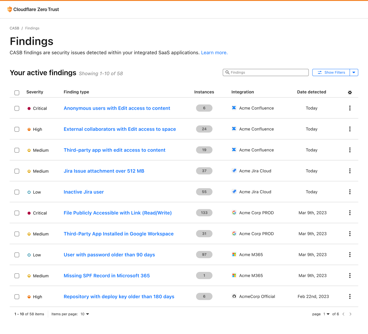
Today, AWS announced a new tenant isolation mode for AWS Lambda, that allows you to process function invocations in separate execution environments for each application end-user or tenant invoking your Lambda function. This capability simplifies building secure multi-tenant SaaS applications by managing tenant-level compute environment isolation and request routing for you. As a result, you can focus on your core business logic rather than implementing your own tenant-aware compute environment isolation.
Overview
Lambda runs your function code in secure execution environments that leverage Firecracker virtualization to provide isolation. These execution environments never share or reuse virtual resources (such as vCPU, disk, or memory) across functions, or even across different versions of the same function. However, Lambda can reuse execution environments for multiple invocations of the same function version, as these execution environments are fully set-up and can therefore deliver faster request processing for your functions.
Figure 1. Incoming invocations processed by a collection of execution environments that belong to a single function.
Multi-tenant SaaS applications that handle sensitive tenant-specific data or execute code supplied dynamically by tenants may need a higher degree of isolation—at the individual application tenant level rather than at the function level—for secure code execution and to reduce the risk of cross-tenant data access.
Prior to today’s launch, developers would implement custom solutions, such as SDKs or application logic to manage isolation within function code. This approach was bug-prone, required more work from application development teams, and didn’t ensure isolation at the compute environment level.
Alternatively, developers adopted the approach of creating separate functions per application tenant, replicating the same code across hundreds or thousands of tenants. This approach provided stronger compute environment isolation than sharing compute environments across multiple tenants of the same function, but increased implementation overhead and operational complexity as workloads grew to support a larger number of tenants over time.
Figure 2. Using function-per-tenant model, each tenant’s requests are processed by a separate function.
Starting today, AWS Lambda offers a new tenant isolation mode that lets you isolate execution environments used across different tenants of your multi-tenant SaaS applications, even when all of the tenants invoke the same function. When you enable the new tenant isolation mode, you include a tenant identifier with each function invocation. Lambda uses this identifier to route the request to the correct execution environment. As a result, each execution environment is reused only for invocations from the same tenant. This means you still get the performance benefits of warm execution environments, while ensuring that each tenant’s workloads remain isolated.
Figure 3. With the new tenant isolation capability, Lambda creates separate execution environments per tenant for a single function.
For organizations handling sensitive tenant-specific data or running untrusted code supplied dynamically by end-users, Lambda’s new tenant isolation mode provides the security benefits of per-tenant compute environment separation without the operational complexity of managing individual functions or infrastructure for each tenant.
Example scenario
Consider building a multi-tenant serverless SaaS application. To optimize performance, your function handler can retrieve tenant-specific configuration and data, cache it in memory, and reuse it for subsequent invocations from the same tenant. For example, you might cache tenant-specific database location, feature flags, or business rules that are frequently accessed during request processing. You may store this information within the application runtime process as global variables or as files in the /tmp directory. However, if the underlying execution environment is used to serve multiple tenants, this approach can potentially expose data across tenants.
With tenant isolation mode you can address this risk with much simpler architecture and configuration. This built-in capability makes Lambda an excellent choice for multi-tenant SaaS applications needing isolated compute environments for individual tenants.
Getting Started with Lambda Tenant Isolation Mode
Use the new tenancy-config parameter to configure tenant isolation mode when you create your function. You can only apply this configuration at function creation time; it cannot be updated for existing functions. The following snippet creates a function with tenancy config using the AWS CLI.
After the function is created, you must provide the tenant ID parameter with each invocation. Lambda uses this identifier to ensure that the execution environment used for a particular tenant is never reused for other tenants. For subsequent invocations from the same tenant, Lambda may reuse the execution environment to optimize performance. Specify this tenant-id parameter as illustrated below:
The new tenant-id parameter is required for functions using the tenant isolation mode. Function invocations omitting this parameter will fail with an invocation error, as shown below:
aws lambda invoke --function-name multitenant-function out.json

An error occurred (InvalidParameterValueException) when calling the Invoke operation:
The invoked function is enabled with tenancy configuration.
Add a valid tenant ID in your request and try again.
Lambda makes the tenant ID parameter available through your function handler’s context object. This allows you to access tenant-specific information in your code, for example if you wish to implement custom logic based on the tenant identity, as shown below:
exports.handler = async function (event, context) {
   const tenantId = context.tenantId;

   // Process tenant-specific logic

   return {
      statusCode: 200,
      body: `OK for tenantId=${tenantId}`
   };
};
The following table outlines differences between Lambda functions with and without tenant isolation mode enabled:
Feature
Without the new tenant isolation mode
With the new tenant isolation mode
Execution environment isolation
Isolated per function version.
Isolated per end-user or tenant invoking a function version.
Execution environment reuse
Can be reused to process all invocations of a function version.
Can only be reused to process invocations from the same tenant invoking a function version.
Data stored on local disk and in-memory
Potentially accessible across all invocations of a function version.
Potentially accessible across invocations from the same tenant. Not accessible for invocations from other tenants.
Cold starts
Occur when there are no warm execution environments available to process incoming invocation.
Occur when there are no tenant-specific warm execution environments available to process incoming invocation. More cold starts expected due to tenant-specific execution environments.
Integrating with Amazon API Gateway
Amazon API Gateway uses Lambda’s Invoke API to invoke Lambda functions. When using the Invoke API, Lambda expects the tenant ID parameter to be passed using the X-Amz-Tenant-Id HTTP header. You can configure API Gateway to inject this HTTP header into the Lambda invocation request with a value obtained from client request properties such as HTTP header, query parameter, or path parameter. When using Lambda Authorizers, you can obtain the value from authorization context information returned by the authorizer, such as principal ID or JWT claim. See API Gateway documentation to learn how you can return authorization information from Lambda authorizers to be used for the X-Amz-Tenant-Id header value.
Figure 4. Obtaining X-Amz-Tenant-Id header value from authentication sources.
The following screenshot illustrates API Gateway Lambda integration configuration, where the incoming request to API Gateway includes an x-tenant-id header that is mapped to the X-Amz-Tenant-Id request header to invoke a Lambda function using tenant isolation mode.
Figure 5. Mapping client request header to Lambda tenant-id header.
The following code snippet illustrates this configuration implemented with the AWS CDK.
const lambdaIntegration = new ApiGw.LambdaIntegration(fn, {
   requestParameters: {
      // This configures API Gateway to inject X-Amz-Tenant-Id header
      // into downstream requests. The header value is obtained from
      // x-tenant-id header in the client request.
      'integration.request.header.X-Amz-Tenant-Id': 'method.request.header.x-tenant-id'
   }
});

resource.addMethod('GET', lambdaIntegration, {
   requestParameters: {
      // This enables API Gateway to use the x-tenant-id header value
      // obtained from the client request. The header name is arbitrary.
      // you can use any other header name.
      'method.request.header.x-tenant-id': true
   }
});
Tenant-aware observability
For functions using tenant isolation, Lambda automatically includes the tenant ID in function logs when you have JSON logging enabled, making it easier to monitor and debug tenant-specific issues. Note that the tenantId property is available during function invocation, rather than during function initialization. The tenantId property is included for both platform events (like platform.start and platform.report) and custom logs you print in your function code, as shown in the following screenshot:
Figure 6. Lambda function logs with tenantId.
Lambda creates a separate CloudWatch log stream for each execution environment. You can use CloudWatch Log Insights to find log streams that belong to a particular tenant by filtering by tenant Id:
fields @logStream, @message
| filter tenantId=='BlueTenant' or record.tenantId=='BlueTenant'
| stats count() as logCount by @logStream
| sort @timestamp desc
You can also retrieve tenant-specific logs across all log streams:
fields @message
| filter tenantId=='BlueTenant' or record.tenantId=='BlueTenant'
| limit 1000
Each log stream starts with function initialization logs followed by the invocation logs. This structure helps you to debug tenant-specific issues and understand the lifecycle of each tenant’s execution environments.
Considerations
When using the new tenant isolation for Lambda functions, consider the following:
Each tenant’s execution environments are isolated from other tenants so that tenant-specific data stored on disk or in memory remain separated from other tenants invoking the same Lambda function.
All tenants share the function’s execution role. For more fine-grained permissions for individual tenants, consider propagating tenant-scoped credentials from the upstream application components invoking your Lambda function.
Your application may experience higher percentage of cold starts, as Lambda processes requests in separate execution environments for each tenant invoking your functions.
You pay a fee for each new tenant-specific execution environment created, depending on the memory configured for your function. See Lambda pricing page for details.
Best practices
When using the new tenant isolation mode for Lambda functions, AWS recommends the following best practices:
Implement robust tenant ID validation at the application layer to prevent unauthorized access through tenant ID manipulation. Consider using a dedicated service or database to maintain valid tenant IDs.
Monitor and audit tenant access patterns regularly to detect potential security anomalies or unauthorized cross-tenant access attempts.
Be aware of Lambda concurrency quotas when building multi-tenant applications. You might need to request quota increases based on your tenant count and usage patterns.
Sample code
Follow the instructions in this GitHub repository to provision a sample project in your own account and see the new Lambda tenant isolation mode in action. The sample project illustrates how to integrate a function using the new tenant isolation mode with Amazon API Gateway and propagate tenant identity from client requests.
Conclusion
The new tenant isolation mode for Lambda simplifies building serverless multi-tenant SaaS applications on AWS. By automatically managing application tenant-level compute environment isolation, this capability eliminates the need for custom isolation logic or separate tenant functions, allowing you to focus on the core business logic while AWS handles the complexities of tenant-aware compute environment isolation.
Combined with the existing security features in Lambda, rapid scaling, and pay-per-use pricing, tenant isolation mode makes Lambda an even more compelling choice for modern SaaS applications, whether you’re building new solutions or enhancing existing ones.
The recent Salesloft breach taught us one thing: connections between SaaS applications are hard to monitor and create blind spots for security teams with disastrous side effects. This will likely not be the last breach of this type.
To fix this, Cloudflare is working towards a set of solutions that consolidates all SaaS connections via a single proxy, for easier monitoring, detection and response. A SaaS to SaaS proxy for everyone.
As we build this, we need feedback from the community, both data owners and SaaS platform providers. If you are interested in gaining early access, please sign up here.
SaaS platform providers, who often offer marketplaces for additional applications, store data on behalf of their customers and ultimately become the trusted guardians. As integrations with marketplace applications take place, that guardianship is put to the test. A key breach in any one of these integrations can lead to widespread data exfiltration and tampering. As more apps are added the attack surface grows larger. Security teams who work for the data owner have no ability, today, to detect and react to any potential breach.
In this post we explain the underlying technology required to make this work and help keep your data on the Internet safe.
SaaS to SaaS integrations
No one disputes the value provided by SaaS applications and their integrations. Major SaaS companies implement flourishing integration ecosystems, often presented as marketplaces. For many, it has become part of their value pitch. Salesforce provides an AppExchange. Zendesk provides a marketplace. ServiceNow provides an Integration Hub. And so forth.
These provide significant value to any organisation and complex workflows. Data analysis or other tasks that are not supported natively by the SaaS vendor are easily carried out via a few clicks.
On the other hand, SaaS applications present security teams with a growing list of unknowns. Who can access this data? What security processes are put in place? And more importantly: how do we detect data leak, compromise, or other malicious intent?
Following the Salesloft breach, which compromised the data of hundreds of companies, including Cloudflare, the answers to these questions are top of mind.
The power of the proxy: seamless observability
There are two approaches Cloudflare is actively prototyping to address the growing security challenges SaaS applications pose, namely visibility into SaaS to SaaS connections, including anomaly detection and key management in the event of a breach. Let’s go over each of these, both relying on proxying SaaS to SaaS traffic.
1) Giving control back to the data owner
Cloudflare runs one of the world’s largest reverse proxy networks. As we terminate L7 traffic, we are able to perform security-related functions including blocking malicious requests, detecting anomalies, detecting automated traffic and so forth. This is one of the main use cases customers approach us for.
Cloudflare can proxy any hostname under the customer’s control.
It is this specific ability, often referred to as “vanity”, “branded” or “custom” hostnames, that allows us to act as a front door to the SaaS vendor on behalf of a customer. Provided a marketplace app integrates via a custom domain, the data owner can choose to use Cloudflare’s new SaaS integration protection capabilities.
For a customer (Acme Corp in this example) to access, say SaaS Application, the URL needs to become saas.acme.com as that is under Acme’s control (and not acme.saas.com).
This setup allows Cloudflare to be placed in front of SaaS Corp as the customer controls the DNS hostname. By proxying traffic, Cloudflare can be the only integration entity with programmatic access to SaaS Corp’s APIs and data and transparently “swap” authorisation tokens with valid ones and issue separate tokens, using key splitting, to any integrations.
Note that in many cases, authorization and authentication flows fall outside any vanity/branded hostname. It is in fact very common for an OAuth flow to still hit the SaaS provider url oauth.saas.com. It is therefore required, in this setup, for marketplace applications to provide the ability to support vanity/branded URLs for their OAuth and similar flows, oauth.saas.acme.com in the diagram above.
Ultimately Cloudflare provides a full L7 reverse proxy for all traffic inbound/outbound to the given SaaS provider solving for the core requirements that would lessen the impact of a similar breach to the Salesloft example. Had Salesloft integrated via a Cloudflare-proxied domain, then data owners would be able to:
Gain visibility into who or what can access data, and where it’s accessed from, in the SaaS platform. Cloudflare already provides analytics and filtering tools to identify traffic sources, including hosting locations, IPs, user agents and other tools.
Instantly shut off access to the SaaS provider without the need to rotate credentials on the SaaS platform, as Cloudflare would be able to block access from the proxy.
Detects anomalies in data access by observing baselines and traffic patterns. For example a change in data exfiltration traffic flows would trigger an alert.
2) Improve SaaS platform security
The approach listed above assumes the end user is the company whose data is at risk. However, SaaS platforms themselves are now paying a lot of attention to marketplace applications and access patterns. From a deployment perspective, it’s actually easier to provide additional visibility to a SaaS provider as it is a standard reverse proxy deployment and we have tools designed for SaaS applications, such as Cloudflare for SaaS.
This deployment model allows Cloudflare to proxy all traffic to the SaaS vendor, including to all API endpoints therefore gaining visibility into any SaaS to SaaS connections. As part of this, we are building improvements to our API Shield solution to provide SaaS security teams with additional controls:
Token / session logging: Ability to keep track of OAuth tokens and provide session logs for audit purposes.
Session anomaly detection: Ability to warn when a given OAuth (or other session) shows anomalous behavior.
Token / session replacement: Ability to substitute SaaS-generated tokens with Cloudflare-generated tokens to allow for fast rotation and access lock down.
The SaaS vendor may of course expose some of the affordances to their end customer as part of their dashboard.
How key splitting enables secure token management
Both deployment approaches described above rely on our ability to control access without storing complete credentials. While we already store SSL/TLS private keys for millions of web applications, storing complete SaaS bearer tokens would create an additional security burden. To solve this, and enable the token swapping and instant revocation capabilities mentioned above, we use key splitting.
Key splitting cryptographically divides bearer tokens into two mathematically interdependent fragments called Part A and Part B. Part A goes to the fourth-party integration (like Drift or Zapier) while Part B stays in Cloudflare’s edge storage. Part A is just random noise that won’t authenticate to Salesforce or any SaaS platform expecting complete tokens, so neither fragment is usable alone.
This creates an un-bypassable control point. Integrations cannot make API calls without going through Cloudflare’s proxy because they only possess Part A. When an integration needs to access data, it must present Part A to our edge where we retrieve Part B, reconstruct the token in memory for microseconds, forward the authenticated request, and then immediately clear the token. This makes sure that the complete bearer token never exists in any database or log.
This forced cooperation means every API call flows through Cloudflare where we can monitor for anomalies, delete Part B to instantly revoke access (transforming incident response from hours to seconds), and maintain complete audit trails. Even more importantly, this approach minimizes our burden of storing sensitive credentials since a breach of our systems wouldn’t yield usable tokens.
If attackers compromise the integration and steal Part A, or somehow breach Cloudflare’s storage and obtain Part B, neither fragment can authenticate on its own. This fundamentally changes the security model from protecting complete tokens to managing split fragments that are individually worthless. It also gives security teams unprecedented visibility and control over how their data is accessed across third-party integrations.
Regaining control of your data
We are excited to develop solutions mentioned above to give better control and visibility around data stored in SaaS environments, or more generally, outside a customer’s network.
If you are a company worried about this risk, and would like to be notified to take part in our early access, please sign up here.
If you are a SaaS vendor who would like to provide feedback and take part in developing better API security tooling for third party integrations towards your platform, sign up here.
We are looking forward to helping you get better control of your data in SaaS to SaaS environments.
Organizations face diverse challenges when it comes to managing encryption keys. While some scenarios demand strict separation, there are compelling use cases where a centralized approach can streamline operations and reduce complexity. In this post, our focus is on a software-as-a-service (SaaS) provider scenario, but the principles we discuss can be adopted by large organization facing similar key management challenges.
Managing encryption across a multi-tenant, multi-service architecture presents a significant challenge. Many organizations find themselves struggling with the complexity and costs associated with provisioning separate AWS Key Management Service (AWS KMS) customer managed keys for each tenant and service. This approach, while secure, often leads to growing operational overhead and increased AWS KMS usage costs over time.
But what if there was a more efficient way?
In this post, we unveil a strategy that uses a single customer managed key (symmetric) per tenant across services. By the end of this post, you’ll learn:
How to implement a scalable, secure, and cost-effective encryption model
Techniques for using one customer managed key per tenant across multiple services and environments
Methods for encrypting tenant data in Amazon DynamoDB and other storage types while maintaining tenant isolation
Multi-tenant encryption requirements for SaaS providers
Data isolation is fundamental to multi-tenant SaaS architectures, serving both compliance requirements and customer confidence. Many SaaS providers need to encrypt sensitive information—from API keys and credentials to personal data—across storage solutions such as DynamoDB and Amazon Simple Storage Service (Amazon S3).
While these storage services provide default encryption at rest, they typically use a single shared key across data items. Consider DynamoDB in a shared pool model, where one table contains data from multiple tenants. In this setup, the tenant data is encrypted using the same AWS KMS Key, regardless of ownership.
KMS key represents a container for top-level key material and is uniquely defined within the KMS, for more information on the different keys involved when encrypting or decrypting data using KMS, see AWS KMS key hierarchy.
This shared-key approach often proves insufficient for SaaS providers operating under strict security and compliance frameworks. Some customers require:
Bring your own key (BYOK) capabilities
Logical isolation of their data through dedicated encryption keys
To meet these requirements, providers can implement customer-specific AWS KMS managed keys, helping to ensure that each customer’s sensitive data remains isolated and inaccessible to other tenants.
Alternatively, providers might consider a silo model with separate tables for each customer. However, this approach introduces its own challenges—as the tenant base grows, managing numerous individual tables becomes increasingly complex and service quota limits might become a constraint.
Managing growth: KMS key management at scale
When scaling a SaaS platform, empowering teams to develop services independently is crucial. A quick way to scale is to have each team develop independently using a dedicated account. This often leads to a decentralized approach where each service manages its own KMS keys per customer. However, this autonomy comes with hidden costs as your customer base and service portfolio expand.
The challenge of key proliferation
As the company grows, the number of keys multiplies with each new customer and service addition. This proliferation creates several organizational challenges:
Cost impact: A single AWS KMS key costs $1 monthly, increasing to a maximum of $3 per month with two or more key rotations.
Operational complexity: Managing many KMS keys across environments and accounts is error-prone and hard to scale.
Organizational waste: Duplicate efforts across teams because each develops and maintains their own code for managing customer key lifecycles.
Governance overhead: It becomes difficult to enforce consistent policies or track KMS key usage across multiple AWS accounts.
A streamlined approach
The solution lies in implementing a centralized key management strategy. One KMS key per tenant, maintained in a central AWS account. This approach effectively addresses the cost, operational, and governance challenges while maintaining security.
In the following sections, we explore how to implement this centralized approach and securely share KMS keys across various services and AWS accounts.
At the heart of our solution lies a centralized tenant key management service (shown as Service A in the following figure). This service handles every aspect of customer KMS key lifecycle—from creation during tenant onboarding to managing aliases, access policies and deletion.
The service achieves secure, scalable key usage across the organization through cross-account AWS Identity and Access Management (IAM) access. It grants other services (for example, the customer-facing service in Account B in the following figure) a permission to perform specific encryption operations using tenant-specific KMS keys through role delegation. This implementation follows AWS best practices for cross-account access, utilizing IAM and AWS Security Token Service (AWS STS) role assumption as described in the AWS documentation and this blog post.
Centralized key management in practice: Encrypting customer data
Let’s examine how this works in practice with a common scenario:
Service A: Our centralized tenant key management service in Account A
Service B: A customer-facing workload running in Account B
When a customer interacts with Service B, it needs to store sensitive information securely, whether that’s secrets, API keys, or license information in a DynamoDB table. Instead of relying on shared KMS keys or default encryption, Service B encrypts data using the customer’s dedicated KMS key managed by Service A. The process works through AWS Identity and Access Management (IAM) role delegation. Service B temporarily assumes a role (ServiceARole) in Account A, receiving fine-grained, scoped down permissions for the specific tenant’s KMS key. With these temporary credentials, Service B can perform client-side encryption operations on sensitive information using the AWS SDK or the AWS Encryption SDK.
In this blog post, we used Boto3. For more advanced use-cases requiring data key caching or keyrings, use the AWS Encryption SDK.
Solution walkthrough
Let’s expand the technical aspects of the solution depicted above. Assumptions and definitions:
Incoming requests include an authentication header with a JSON Web Token (JWT) that includes data identifying the current tenant’s ID. These tokens are signed by an identity provider, making sure that the JWT cannot be modified, and the tenant identity can be trusted.
Account A: Centralized key management service.
Account B: Business service that serves customer requests.
alias/customer-<tenant-id> is the format of the aliases in account A. Each alias points to the KMS key of the corresponding customer identified by value of <tenant-id>. Service A creates these aliases during tenant onboarding and deletes them during tenant offboarding.
ServiceARole: A role in Account A that can encrypt and decrypt a KMS key that has an alias prefixed with alias/customer-*. The permissions are scoped down further using session policies when ServiceBRole assumes ServiceARole.
ServiceBRole: A role in Account B that can assume ServiceARole in Account A to gain access to the customer’s KMS key. This will be the AWS Lambda function’s execution role.
Note that Service B’s compute layer in this case is a Lambda function, but the solution works for other compute architectures. Let’s go over the flow in more detail:
Use service with JWT
A customer who belongs to a tenant signs in to the SaaS solution and is given a JWT that identifies its tenants with a tenant ID (<tenant-id>). The customer makes an action in ServiceB and sends sensitive information.
ServiceB handles the request (in a Lambda function), verifies the JWT token and wants to:
Encrypt the customer’s sensitive data
Save the encrypted data along with other data in the DynamoDB table
To encrypt tenant secrets securely and at scale, we grant application roles cross-account access to KMS keys—but only through their alias, which maps to a tenant identifier present in their JWT authentication token, enforcing strong isolation.
Depending on your environment, you can add additional conditions to this trust policy to further reduce the scope of who can assume this role. For more information, see IAM and AWS STS condition context keys.
Then, each KMS customer managed key will have the following policy. For example, a KMS key for a customer with <tenant-id>: 123 will have a policy that restricts access to the key using the specific customer alias and only through ServiceRoleA.
The following is a Python code example demonstrating how Service B dynamically assumes a role in Account A to encrypt data for a specific tenant using a session-scoped IAM policy that allows access only to that tenant’s KMS key alias.
This pattern follows the same principles outlined in Isolating SaaS Tenants with Dynamically Generated IAM Policies. The idea is to generate and attach a tenant-specific IAM policy at runtime, granting the minimum required permissions to operate on tenant-owned resources—in this case, a KMS key alias. The credentials will allow the Lambda function to use only the KMS key that belongs to a customer (identified by tenant_id).
We will call the assume_role_for_tenant for every tenant.
The condition of "StringEquals" - "kms:RequestAlias": alias is the magical AWS STS sauce, it restricts ServiceB to use the current tenant’s alias in its encryption SDK calls and relies on alias authorization
import boto3
def assume_role_for_tenant(tenant_id: str):
    alias = f"alias/customer-{tenant_id}"
    # Session policy scoped to only the specific alias
    session_policy = {
        "Version": "2012-10-17",
        "Statement": [
            {
                "Effect": "Allow",
                "Action": [
                    "kms:Encrypt",
                    "kms:Decrypt",
                    "kms:GenerateDataKey*"
                ],
                "Resource": "*",
                "Condition": {
                    "StringEquals": {
                        "kms:RequestAlias": alias
                    }
                }
            }
        ]
    }
    # Assume ServiceARole in Account A with inline session policy
    sts = boto3.client("sts")
    assumed = sts.assume_role(
        RoleArn="arn:aws:iam::<ACCOUNT_A_ID>:role/ServiceARole",
        RoleSessionName=f"Tenant{tenant_id}Session",
        Policy=json.dumps(session_policy)
    )
    return assumed["Credentials"]
Encrypt data and save in DynamoDB
Now, what remains to do is use the assumed role credentials and use AWS SDK to encrypt the sensitive customer data and store it in the DynamoDB table.
# Use temporary credentials to create a KMS client
    creds = assume_role_for_tenant(tenant_id, plaintext)
    kms = boto3.client(
        "kms",
        region_name="us-east-1",
        aws_access_key_id=creds["AccessKeyId"],
        aws_secret_access_key=creds["SecretAccessKey"],
        aws_session_token=creds["SessionToken"]
    )
    # Encrypt using the alias
    response = kms.encrypt(
        KeyId= f"alias/customer-{tenant_id}"
        Plaintext=plaintext
    )
    # store response["CiphertextBlob"] in DynamoDB table
This post doesn’t address isolation between different services, only between tenants. If such service isolation is required, you can use encryption context, an optional set of non-secret key/value pairs that can contain additional contextual information about the data, for example the service identifier. This helps ensure that services can only encrypt or decrypt data using the relevant service encryption context.
Benefits of centralized key management
Let’s examine how this solution addresses our earlier challenges.
Tenant isolation by design
Despite reducing the total number of KMS keys, we maintain strict tenant isolation. Each customer’s sensitive data remains encrypted with their dedicated key, identified by a unique alias (alias/customer-<tenant-id>). Access control to the tenant key is tightly managed through IAM role delegation, following least privilege principles:
Service A exclusively controls the management of the tenants’ KMS keys.
Service B can only assume a role that grants restricted encrypt, decrypt, and GenerateDataKey access for the customer managed key designated by the alias: alias/customer-<tenant-id>.
Optimized cost management
Our approach significantly reduces costs by moving from multiple service-specific KMS keys per tenant to a single KMS key per tenant that is shared securely across services and environments. This behavior introduces a new centralized account (Account A) that provides access to encryption keys under the right circumstances. It is important to understand AWS STS limits, specifically for AssumeRole calls and consider temporary IAM credentials caching mechanisms if those limits become a bottleneck. Additionally, if KMS limits are a bottleneck, consider using data key caching by using the AWS Encryption SDK.
Streamlined operations and governance
By centralizing key management in Service A, you can achieve:
Consistent KMS key lifecycle management across the organization
Improved audit capabilities using AWS CloudTrail to better understand key access patterns by service
Reduced operational overhead
Simplified compliance monitoring
The only additional complexity is the initial cross-account role delegation setup between Service A and other services. After being established, this framework can be scaled to accommodate new tenants and services.
It’s best to encapsulate the assume-role logic, policy generation, and AWS SDK client initialization within a shared organization-wide SDK. This abstraction reduces cognitive load for developers and minimizes the risk of misconfigurations. You can take it a step further by exposing high-level utility functions such as encrypt_tenant_data() and decrypt_tenant_data(), hiding the underlying complexity while promoting secure and consistent usage patterns across teams.
Conclusion
In this post, we explored an efficient approach to managing encryption keys in a multi-tenant SaaS environment through centralization. We examined common challenges faced by growing SaaS providers, including key proliferation, rising costs, and operational complexity across multiple AWS accounts and services. The solution, centralizing key management, uses AWS best practices for IAM role delegation and cross-account access, enabling organizations to maintain security and compliance while reducing operational overhead. By implementing this approach, SaaS providers or large organizations facing similar challenges can effectively manage their encryption infrastructure as they scale, without compromising on security or increasing complexity.
SMS messaging continues to be one of the most reliable and effective communication channels. However, for Software as a Service (SaaS) companies, Independent Software Vendors (ISVs), and multi-tenant solution providers looking to incorporate SMS capabilities into their offerings, the journey can be complex and filled with challenges.
This guide is specifically designed for technology providers—whether you’re a SaaS company, an ISV, or any platform that enables your customers to send SMS messages to their end users. Throughout this article, the following terminology will be used:
Provider: An organization offering SMS capabilities as part of your product or service
Customer: The entities using Provider technology to send SMS messages
End User: The recipients who opt in to receive SMS messages from Customers
The landscape of SMS implementation can be complicated, with varying country-specific regulations, lengthy registration processes that can take weeks or even months, different originator types (Long Code, Short Code, Sender ID, etc.) with unique capabilities, and the diverse needs of Customers and End Users. These challenges are amplified when you’re a Provider offering SMS services to your own Customers, who in turn serve their End Users.
By the end of this guide, you’ll understand:
How opt-in influences architecture
Options for how to structure your SMS offering to Customers
Strategies for reducing friction in the SMS implementation process
Let’s dive in.
The Registration Dilemma: Who Owns the Relationship?
One of the most critical decisions for your SMS Originator registration is determining whose information is used to apply. The biggest mistake AWS sees Providers make is not knowing how their relationship with their Customers and their Customers’ End Users affects their architecture and how they complete any registrations that are necessary.
Mobile carriers want to know who will be sending SMS to their customers, how that entity will opt them in, and what content they will be sending. When registering for originators, especially in the United States, you will need to succinctly explain how End Users will opt in and how that data will not be shared with any third parties. Your architecture must ensure:
Clear opt-in processes that name the correct entity
Compliance with third-party data sharing regulations
AWS consistently sees Providers register themselves when obtaining an Originator when they do not have a relationship with their Customers’ End Users. The decision of whose information belongs in the registration hinges primarily on a fundamental question: Who does the End User believe they’re entering into a relationship with when they provide their phone number?
The most common scenarios are below:
Scenario 1: End Users interact with the Customer’s brand only
In most cases, End Users are completely unaware of your existence as the Provider. They believe they’re opting in to receive messages from your Customer directly. In this scenario:
Registration should be completed using the Customer’s information. There are many ways you can facilitate this process and some ways to reduce this common friction point will be discussed later in this post.
Messages should appear to come from the Customer, not the Provider, your service name should not appear in messaging
Scenario 2: End Users explicitly opt in through the Provider application
In some cases, End Users clearly understand they’re opting in to receive messages via your technology platform, on behalf of your Customer. The opt-in data will not be shared with your Customers and your brand, as the Provider, will be the named entity in all SMS sent.
There are a number of ways that this can happen:
End Users could opt in using a widget you build that your Customers install on their site or in their app
A paper form or verbal script that you supply that clearly identifies you, the Provider
AWS commonly sees this occurring with Providers that supply:
Third-party payment processing
Shipping and logistics support
Customer service platforms
One-Time Password (OTP) capabilities
In this scenario your company name would typically appear in the messaging and registration would use your company information.
NOTE: There are edge cases to these two scenarios but the implementation can be complicated, so if you are a Provider and you don’t think that you fit into these two scenarios above make sure to reach out to your Account Manager, open a case, or speak to a specialist before starting to implement anything.
Architectural Models for SMS Implementation
Let’s explore various architectural models for structuring your SMS offering based on your business needs and Customer relationships. Each model has distinct characteristics in the following areas:
1. “Bring Your Own AWS Account” Model
Who does the registration and configuration?
The Customer connects their own AWS account, so the registration and any configuration happens in the Customer account.
Usually in this scenario the information that is input into the registration is the Customer’s since it’s their account
Customer responsibilities:
Customer handles all registration and configuration requirements themselves
Customer integrates their account with the Provider service
Customer manages sending, opt-out lists, etc.
Pays the AWS bill
Provider responsibilities:
The Provider offers a user-friendly interface that calls the AWS End User Messaging Service APIs using the Customer’s credentials.
The depth of services offered by the Provider can vary
Best for: Technical Customers who want full control and already use AWS; Providers who want to avoid registration and configuration complexities.
2. Provider Account – Manual Registration and Configuration
Who does the registration and configuration?
The Provider owns the account and is not providing the Customer with a way to submit their own information so the Provider must enter the information
The Customer’s information is captured manually
The Provider handles the complexity of registration and configuration through the console
Customer responsibilities:
Provide necessary information to the Provider for registration purposes
Provider responsibilities:
Captures the registration information manually from Customers.
Manages the complexity on behalf of your Customers.
This can be implemented either with separate AWS accounts for each Customer or a multi-tenant architecture in a single account.
Best for: Providers with a small number of high-value Customers who need hand-holding through the SMS implementation process.
3. Semi-Automated Solution – Customer Sending
Who does the registration and configuration?
The Provider builds a way for the Customer to submit their registration information, which the Provider then programmatically submits to carriers/regulators.
Customer responsibilities:
Your platform manages the technical configuration and provides sending capabilities, but the Customer is responsible for maintaining compliance.
Provider responsibilities:
You provide a streamlined way for Customers to submit registration information (webhooks, forms, APIs).
You programmatically submit the registration data to carriers/regulators.
You manage the technical configuration and provide sending capabilities.
Best for: Providers with moderate technical sophistication who want to reduce friction while maintaining separation of regulatory responsibilities.
4. Fully Automated Solution – Provider Sending
Who does the registration and configuration?
The Customer’s information is used in the registration, which you handle programmatically.
Customer responsibilities:
You handle all technical aspects of registration, but the Customer is still responsible for maintaining messaging compliance.
Provider responsibilities:
You provide hosted, customizable Terms & Conditions and Privacy Policies for each Customer that are compliant out of the box.
You offer compliant opt-in pathways (web forms, verbal scripts, etc.).
You handle all technical aspects of registration.
Best for: Large-scale Providers serving many Customers with varying levels of technical sophistication.
5. Template-Restricted Fully Automated Messaging
Who does the registration and configuration?
The Customer’s information is used in the registration, which you handle programmatically.
Customer responsibilities:
You manage all regulatory compliance centrally, and the Customer can only personalize specific fields in pre-approved message templates.
Provider responsibilities:
You provide a suite of pre-approved message templates.
You manage all regulatory compliance centrally.
You simplify the registration process since the content is tightly controlled.
Best for: Use cases with predictable messaging needs like appointment reminders, shipping notifications, or one-time passwords.
6. Fully Managed Programs
Who does the registration and configuration?
The Customer authorizes you to send messages on their behalf, so you own the relationship with the end-user and the registration.
Customer responsibilities:
Only required to give you any pertinent information necessary for you to send messages to the End-Users. This could be things like tracking numbers or other information that the particular use case requires and is part of the personalization that is allowed.
Provider responsibilities:
You manage all aspects of the end-user relationship.
You control the entire messaging experience, including opt-in collection and the end-user relationship.
Example: A shipping notification service might send messages like: “ShipTrack: Your order from ACME Corp will arrive tomorrow. Track at [link]”
Best for: Specialized use cases where your platform adds significant value as an identified intermediary.
Shaping Your SMS Offering: Strategic Considerations
Pricing Strategies
When incorporating SMS into your product, one of the first considerations is how to structure your pricing. Unlike many digital services with predictable costs, SMS pricing varies significantly based on destination country, originator type, and volume.
AWS End User Messaging Service bills based on volume sent per country, with each country having its own price point. This pricing is determined by the recipient’s handset country code, not their physical location. This means that even if you primarily serve U.S. based Customers, you may need to account for international rates when recipients have non-U.S. phone numbers.
There are also one-time and ongoing fees to be accounted for. Registrations often have one-time processing fees and Originators can have leasing costs that range from free to more than $1,000 a month for short codes in some countries. Make sure that you think through how those costs will or will not be passed to your Customers.
As you design your pricing model, consider these common volume based approaches:
SMS Credits: Create a standardized credit system where Customers purchase credits regardless of destination country. You would internally manage the conversion between credits and actual costs.
Dollar-Based Allocation: Provide Customers with a budget that gets depleted based on actual costs per message sent.
Tiered Country Pricing: Group countries into tiers (e.g., Tier 1 for North America, Tier 2 for Western Europe) with different pricing for each tier.
Bundled Messaging: Include a certain number of messages in your base subscription with overage fees for additional messages.
Each approach has trade-offs in terms of simplicity, transparency, and risk management. Your decision should align with your overall business model and Customer expectations.
Geographic Considerations
Different countries have distinct regulatory requirements for SMS messaging, including:
Originator Support: Not all countries support all originator types, view the details here
Originator Selection: In cases where multiple types of originators are supported, how do you support your Customer in selecting the right originator for the right use case?
Registration: An increasing numbers of countries require you to register before being allowed to send
Quiet hours: Many countries restrict when promotional messages can be sent
Content restrictions: Certain types of content (gambling, alcohol, adult content, etc.) may be prohibited or heavily restricted. A more comprehensive list can be found here
Template requirements: Some jurisdictions require pre-approval of message templates
Sender ID regulations: Rules regarding who can use alphanumeric sender IDs vary widely
As a Provider, you need to decide which countries you’ll support and how you’ll ensure compliance across markets. This decision affects not just your pricing but your entire product architecture, especially if you serve global Customers.
Strategies to Reduce Implementation Friction
Implementing SMS can be complex for your Customers. Here are some strategies that can simplify and/or streamline the process. Some of these can be mixed and matched and could also be used as a value-add or even as a paid offering to your Customers:
Create customizable, compliant templates for Privacy Policies and Terms & Conditions that your Customers can use. This ensures proper disclosure of SMS practices without requiring Customers to update their own legal documents.
Registration Webforms and Workflows
Develop user-friendly webforms that collect all required registration information in a guided process. These can significantly simplify complex registrations like 10DLC brand and campaign registration.
Below, Figures 1-3, you will find several examples of compliant forms that could be customized for your use:
Fig. 1
Fig. 2
Fig. 3
Pre-Approved Opt-In Widgets
Create embeddable widgets, such as Figures 1-3 above, that your Customers can add to their websites or apps that implement compliant opt-in processes. These can include all required disclosures and confirmations while being easy to integrate.
Template Libraries
Provide a library of pre-approved message templates for common use cases. This reduces compliance risks and simplifies the sending process for your Customers.
Testing Environments
Create sandbox environments where Customers can test their SMS implementation before going live. This helps catch issues with formatting, opt-in processes, or content compliance.
Documentation and Training
Develop clear documentation and training resources specific to each originator type and use case. This empowers your Customers while reducing support burden.
Conclusion
Incorporating SMS capabilities into your platform can enhance Customer engagement, but the journey can be complex. This guide has explored key considerations to help you navigate it successfully.
This post examined various architectural models, each with tradeoffs in Customer responsibilities and Provider responsibilities. This post reviewed strategic factors like pricing, geographic regulations, and originator types that must be carefully considered. Finally, practical strategies to reduce implementation friction for Customers such as hosted compliance documents, streamlined registration workflows, and pre-approved templates, you can use to simplify the integration process were discussed .
The critical first step though, is understanding the relationship between you as the Provider, your Customers, and their End Users. This shapes whose information is used for originator registration, which in turn defines the SMS experience.
Ultimately, a successful SMS solution requires balancing technical, regulatory, and Customer-centric factors. Leveraging this guidance will equip you to design and deploy an offering that delights your Customers and their End Users.
Today, I’m happy to announce the general availability of Amazon CloudFront SaaS Manager, a new feature that helps software-as-a-service (SaaS) providers, web development platform providers, and companies with multiple brands and websites efficiently manage delivery across multiple domains. Customers already use CloudFront to securely deliver content with low latency and high transfer speeds. CloudFront SaaS Manager addresses a critical challenge these organizations face: managing tenant websites at scale, each requiring TLS certificates, distributed denial-of-service (DDoS) protection, and performance monitoring.
With CloudFront Saas Manager, web development platform providers and enterprise SaaS providers who manage a large number of domains will use simple APIs and reusable configurations that use CloudFront edge locations worldwide, AWS WAF, and AWS Certificate Manager. CloudFront SaaS Manager can dramatically reduce operational complexity while providing high-performance content delivery and enterprise-grade security for every customer domain.
How it works In CloudFront, you can use multi-tenant SaaS deployments, a strategy where a single CloudFront distribution serves content for multiple distinct tenants (users or organizations). CloudFront SaaS Manager uses a new template-based distribution model called a multi-tenant distribution to serve content across multiple domains while sharing configuration and infrastructure. However, if supporting single websites or application, a standard distribution would be better or recommended.
A template distribution defines the base configuration that will be used across domains such as origin configurations, cache behaviors, and security settings. Each template distribution has a distribution tenant to represent domain-specific origin paths or origin domain names including web access control list (ACL) overrides and custom TLS certificates.
Optionally, multiple distribution tenants can use the same connection group that provides the CloudFront routing endpoint that serves content to viewers. DNS records point to the CloudFront endpoint of the connection group using a Canonical Name Record (CNAME).
CloudFront SaaS Manager in action I’d like to give you an example to help you understand the capabilities of CloudFront SaaS Manager. You have a company called MyStore, a popular e-commerce platform that helps your customer easily set up and manage an online store. MyStore’s tenants already enjoy outstanding customer service, security, reliability, and ease-of-use with little setup required to get a store up and running, resulting in 99.95 percent uptime for the last 12 months.
Customers of MyStore are unevenly distributed across three different pricing tiers: Bronze, Silver, and Gold, and each customer is assigned a persistent mystore.app subdomain. You can apply these tiers to different customer segments, customized settings, and operational Regions. For example, you can add AWS WAF service in the Gold tier as an advanced feature. In this example, MyStore has decided not to maintain their own web servers to handle TLS connections and security for a growing number of applications hosted on their platform. They are evaluating CloudFront to see if that will help them reduce operational overhead.
Let’s find how as MyStore you configure your customer’s websites distributed in multiple tiers with the CloudFront SaaS Manager. To get started, you can create a multi-tenant distribution that acts as a template corresponding to each of the three pricing tiers the MyStore offers: Bronze, Sliver, and Gold shown in Multi-tenant distribution under the SaaS menu on the Amazon CloudFront console.
To create a multi-tenant distribution, choose Create distribution and select Multi-tenant architecture if you have multiple websites or applications that will share the same configuration. Follow the steps to provide basic details such as a name for your distribution, tags, and wildcard certificate, specify origin type and location for your content such as a website or app, and enable security protections with AWS WAF web ACL feature.
When the multi-tenant distribution is created successfully, you can create a distribution tenant by choosing Create tenant in the Distribution tenants menu in the left navigation pane. You can create a distribution tenant to add your active customer to be associated with the Bronze tier.
Each tenant can be associated with up to one multi-tenant distribution. You can add one or more domains of your customers to a distribution tenant and assign custom parameter values such as origin domains and origin paths. A distribution tenant can inherit the TLS certificate and security configuration of its associated multi-tenant distribution. You can also attach a new certificate specifically for the tenant, or you can override the tenant security configuration.
When the distribution tenant is created successfully, you can finalize this step by updating a DNS record to route traffic to the domain in this distribution tenant and creating a CNAME pointed to the CloudFront application endpoint. To learn more, visit Create a distribution in the Amazon CloudFront Developer Guide.
Now you can see all customers in each distribution tenant to associate multi-tenant distributions.
By increasing customers’ business needs, you can upgrade your customers from Bronze to Silver tiers by moving those distribution tenants to a proper multi-tenant distribution.
During the monthly maintenance process, we identify domains associated with inactive customer accounts that can be safely decommissioned. If you’ve decided to deprecate the Bronze tier and migrate all customers who are currently in the Bronze tier to the Silver tier, then you can delete a multi-tenant distribution to associate the Bronze tier. To learn more, visit Update a distribution or Distribution tenant customizations in the Amazon CloudFront Developer Guide.
By default, your AWS account has one connection group that handles all your CloudFront traffic. You can enable Connection group in the Settings menu in the left navigation pane to create additional connection groups, giving you more control over traffic management and tenant isolation.
(This survey is hosted by an external company. AWS handles your information as described in the AWS Privacy Notice. AWS will own the data gathered via this survey and will not share the information collected with survey respondents.)
Software as a Service (SaaS) applications offer a transformative solution for businesses worldwide, delivering on-demand software solutions to a global audience. However, building a successful SaaS platform demands on meticulous architectural planning, especially given the inherent challenges of multi-tenancy. It’s also essential to ensure that each tenant’s data remains isolated and protected from unauthorized access and that multi-tenant systems are cost-optimized and can sustain the scaling of the SaaS business provider.
In this blog post, we will explore some of the key elements and best practices for designing and deploying secure and efficient SaaS systems on AWS.
Cost is a key factor to consider when we design new systems. Multi-tenancy requires teams to think beyond the basics of auto scaling, adopting strategies to allow their architecture to support a complex cost-scaling challenges. In this session, the speaker covers some design patterns for distributed systems to support the continually evolving scale needs of the environment, while optimizing the cost of the infrastructure.
Figure 1. The architectural model chosen for deploying multi-tenant systems—pooled, siloed, or mixed—significantly influences the cost-optimization strategy. Each approach offers distinct trade-offs in terms of resource allocation, scalability, and cost efficiency.
The SaaS Lens for the AWS Well-Architected Framework empowers customers to assess and enhance their cloud-based architectures, fostering a deeper understanding of the business implications of their design choices. By bringing together technical leadership and diverse teams to discuss strategies for improving various aspects of the system, the AWS Well-Architected Framework facilitates collaborative decision-making. Moreover, the AWS account team can provide valuable support in conducting these assessments, offering expert guidance and insights. The AWS SaaS Lens specifically focuses on how to design, deploy, and architect multi-tenant SaaS application workloads within the AWS Cloud.
Figure 2. The microservices running in a multi-tenant environment must be able to reference and apply tenant context within each service. At the same time, it’s also our goal to limit the degree to which developers need to introduce any tenant awareness into their code.
Not every SaaS provider has the luxury of running all the moving parts of their solution within their own infrastructure. SaaS teams might support a range of diverse system models, where architectures might include customer-hosted data, edge deployment for parts of the application, and on-premises components. In this session, you can learn the strategies to support the complexities of this distributed model without undermining the resilience, operational efficiency, and agility goals of your solution. The video covers how this influences the onboarding, deployment, and profile management of the SaaS environment.
Figure 3. In this architectural pattern, tenants are demanding to have the ML workload in their environment. So, the SaaS provider only manages the SaaS control plane where tenants deploy the application plane in their environment, including the ML workload and the necessary components around it.
Containers are frequently employed in multi-tenant SaaS environments to enhance scalability, isolation, and resource efficiency. Developing such systems requires addressing multiple challenges, including tenant isolation, tenant on-boarding, tenant-specific metering, monitoring, and other factors related to multi-tenancy. This session explores how to effectively manage all of these aspects when deploying solutions on AWS Fargate.
Figure 4. Microservices architecture can enhance security isolation by dividing applications into smaller, independent services, reducing the potential impact of a breach.
Serverless helps to create multi-tenant architectures thanks to services like AWS Lambda that isolate your business logic per request, making them the perfect companion to run a SaaS platform. This workshop provides a hands-on introduction to creating serverless multi-tenant SaaS applications, helping you get started and gain practical experience.
Figure 5. This is the high-level architecture of the web application you will use in the AWS Serverless SaaS Workshop. In the labs, you will use this web application to add features that are needed to build this final SaaS application.
Thanks for reading! Multi-tenant SaaS architectures require a careful design of your system. In this post, you have discovered key elements for properly designing your next SaaS workloads. In the next blog, we will talk about modern data architectures.
To revisit any of our previous posts or explore the entire series, visit the Let’s Architect! page.
Chrome and Mozilla announced that they will stop trusting Entrust’s public TLS certificates issued after November 12, 2024 and December 1, 2024, respectively. This decision stems from concerns related to Entrust’s ability to meet the CA/Browser Forum’s requirements for a publicly trusted certificate authority (CA). To prevent Entrust customers from being impacted by this change, Entrust has announced that they are partnering with SSL.com, a publicly trusted CA, and will be issuing certs from SSL.com’s roots to ensure that they can continue to provide their customers with certificates that are trusted by Chrome and Mozilla.
We’re excited to announce that we’re going to be adding SSL.com as a certificate authority that Cloudflare customers can use. This means that Cloudflare customers that are currently relying on Entrust as a CA and uploading their certificate manually to Cloudflare will now be able to rely on Cloudflare’s certificate management pipeline for automatic issuance and renewal of SSL.com certificates.
CA distrust: responsibilities, repercussions, and responses
With great power comes great responsibility Every publicly trusted certificate authority (CA) is responsible for maintaining a high standard of security and compliance to ensure that the certificates they issue are trustworthy. The security of millions of websites and applications relies on a CA’s commitment to these standards, which are set by the CA/Browser Forum, the governing body that defines the baseline requirements for certificate authorities. These standards include rules regarding certificate issuance, validation, and revocation, all designed to secure the data transferred over the Internet.
However, as with all complex software systems, it’s inevitable that bugs or issues may arise, leading to the mis-issuance of certificates. Improperly issued certificates pose a significant risk to Internet security, as they can be exploited by malicious actors to impersonate legitimate websites and intercept sensitive data.
To mitigate such risk, publicly trusted CAs are required to communicate issues as soon as they are discovered, so that domain owners can replace the compromised certificates immediately. Once the issue is communicated, CAs must revoke the mis-issued certificates within 5 days to signal to browsers and clients that the compromised certificate should no longer be trusted. This level of transparency and urgency around the revocation process is essential for minimizing the risk posed by compromised certificates.
Why Chrome and Mozilla are distrusting Entrust The decision made by Chrome and Mozilla to distrust Entrust’s public TLS certificates stems from concerns regarding Entrust’s incident response and remediation process. In several instances, Entrust failed to report critical issues and did not revoke certificates in a timely manner. The pattern of delayed action has eroded the browsers’ confidence in Entrust’s ability to act quickly and transparently, which is crucial for maintaining trust as a CA.
Google and Mozilla cited the ongoing lack of transparency and urgency in addressing mis-issuances as the primary reason for their distrust decision. Google specifically pointed out that over the past 6 years, Entrust has shown a “pattern of compliance failures” and failed to make the “tangible, measurable progress” necessary to restore trust. Mozilla echoed these concerns, emphasizing the importance of holding Entrust accountable to ensure the integrity and security of the public Internet.
Entrust’s response to the distrust announcement In response to the distrust announcement from Chrome and Mozilla, Entrust has taken proactive steps to ensure continuity for their customers. To prevent service disruption, Entrust has announced that they are partnering with SSL.com, a CA that’s trusted by all major browsers, including Chrome and Mozilla, to issue certificates for their customers. By issuing certificates from SSL.com’s roots, Entrust aims to provide a seamless transition for their customers, ensuring that they can continue to obtain certificates that are recognized and trusted by the browsers their users rely on.
In addition to their partnership with SSL.com, Entrust stated that they are working on a number of improvements, including changes to their organizational structure, revisions to their incident response process and policies, and a push towards automation to ensure compliant certificate issuances.
How Cloudflare can help Entrust customers
Now available: SSL.com as a certificate authority for Advanced Certificate Manager and SSL for SaaS certificates We’re excited to announce that customers using Advanced Certificate Manager will now be able to select SSL.com as a certificate authority for Advanced certificates and Total TLS certificates. Once the certificate is issued, Cloudflare will handle all future renewals on your behalf.
By default, Cloudflare will issue SSL.com certificates with a 90 day validity period. However, customers using Advanced Certificate Manager will have the option to set a custom validity period (14, 30, or 90 days) for their SSL.com certificates. In addition, Enterprise customers will have the option to obtain 1-year SSL.com certificates. Every SSL.com certificate order will include 1 RSA and 1 ECDSA certificate.
Note: We are gradually rolling this out and customers should see the CA become available to them through the end of September and into October.
If you’re using Cloudflare as your DNS provider, there are no additional steps for you to take to get the certificate issued. Cloudflare will validate the ownership of the domain on your behalf to get your SSL.com certificate issued and renewed.
If you’re using an external DNS provider and have wildcard hostnames on your certificates, DNS based validation will need to be used, which means that you’ll need to add TXT DCV tokens at your DNS provider in order to get the certificate issued. With SSL.com, two tokens are returned for every hostname on the certificate. This is because SSL.com uses different tokens for the RSA and ECDSA certificates. To reduce the overhead around certificate management, we recommend setting up DCV Delegation to allow Cloudflare to place domain control validation (DCV) tokens on your behalf. Once DCV Delegation is set up, Cloudflare will automatically issue, renew, and deploy all future certificates for you.
Advanced Certificates: selecting SSL.com as a CA through the UI or API Customers can select SSL.com as a CA through the UI or through the Advanced Certificate API endpoint by specifying “ssl_com” in the certificate_authority parameter.
If you’d like to use SSL.com as a CA for an advanced certificate, you can select “SSL.com” as your CA when creating a new Advanced certificate order.
If you’d like to use SSL.com as a CA for all of your certificates, we recommend setting your Total TLS CA to SSL.com. This will issue an individual certificate for each of your proxied hostname from the CA.
Note: Total TLS is a feature that’s only available to customers that are using Cloudflare as their DNS provider.
SSL for SaaS: selecting SSL.com as a CA through the UI or API Enterprise customers can select SSL.com as a CA through the custom hostname creation UI or through the Custom Hostnames API endpoint by specifying “ssl_com” in the certificate_authority parameter.
All custom hostname certificates issued from SSL.com will have a 90 day validity period. If you have wildcard support enabled for custom hostnames, we recommend using DCV Delegation to ensure that all certificate issuances and renewals are automatic.
Our recommendation if you’re using Entrust as a certificate authority
Cloudflare customers that use Entrust as their CA are required to manually handle all certificate issuances and renewals. Since Cloudflare does not directly integrate with Entrust, customers have to get their certificates issued directly from the CA and upload them to Cloudflare as custom certificates. Once these certificates come up for renewal, customers have to repeat this manual process and upload the renewed certificates to Cloudflare before the expiration date.
Manually managing your certificate’s lifecycle is a time-consuming and error prone process. With certificate lifetimes decreasing from 1 year to 90 days, this cycle needs to be repeated more frequently by the domain owner.
As Entrust transitions to issuing certificates from SSL.com roots, this manual management process will remain unless customers switch to Cloudflare’s managed certificate pipeline. By making this switch, you can continue to receive SSL.com certificates without the hassle of manual management — Cloudflare will handle all issuances and renewals for you!
In early October, we will be reaching out to customers who have uploaded Entrust certificates to Cloudflare to recommend migrating to our managed pipeline for SSL.com certificate issuances, simplifying your certificate management process.
If you’re ready to make the transition today, simply go to the SSL/TLS tab in your Cloudflare dashboard, click “Order Advanced Certificate”, and select “SSL.com” as your certificate authority. Once your new SSL.com certificate is issued, you can either remove your Entrust certificate or simply let it expire. Cloudflare will seamlessly transition to serving the managed SSL.com certificate before the Entrust certificate expires, ensuring zero downtime during the switch.
Customers of all sizes and industries use Software-as-a-Service (SaaS) applications to host their workloads. Most SaaS solutions take care of maintenance and upgrades of the application for you, and get you up and running in a relatively short timeframe. Why spend time, money, and your precious resources to build and maintain applications when this could be offloaded?
However, working with SaaS solutions can introduce new requirements for integration. This blog post shows you how Wesfarmers Health was able to introduce an upstream architecture using serverless technologies in order to work with integration constraints.
At the end of the post, you will see the final architecture and a sample repository for you to download and adjust for your use case.
Let’s get started!
Consent capture problem
Wesfarmers Health used a SaaS solution to capture consent. When capturing consent for a user, order guarantee and delivery semantics become important. Failure to correctly capture consent choice can lead to downstream systems making non-compliant decisions. This can end up in penalties, financial or otherwise, and might even lead to brand reputation damage.
In Wesfarmers’ case, the integration options did not support a queue with order guarantee nor exactly-once processing. This meant that, with enough load and chance, a user’s preference might be captured incorrectly. Let’s look at two scenarios where this could happen.
In both of these scenarios, the user makes a choice, and quickly changes their mind. These are considered two discreet events:
Event 1 – User confirms “yes.”
Event 2 – User then quickly changes their mind to confirm “no.”
Scenario 1: Incorrect order
In this scenario, two events end up in a queue with no order guarantee. Event 2 might be processed before Event 1, so although the user provided a “no,” the system has now captured a “yes.” This is now considered a non-compliant consent capture.
Figure 1. Animation showing messages processed in the wrong order
Scenario 2 – events processed multiple times
In this scenario, perhaps due to the load, Event 1 was transmitted twice, once before and once after Event 2, due to at least once processing. In this scenario, the user’s record could be updated three times, first with Event 1 with “yes,” then Event 2 with “no,” then again with retransmitted Event 1 with “yes,” which ultimately ends up with a “yes,” also considered a non-compliant consent capture.
Figure 2. Animation showing messages processed multiple times
How did Amazon SQS and Amazon DynamoDB help with order?
With Amazon Amazon Simple Queue Service (Amazon SQS), queues come in two flavors: standard and first-in-first-out (FIFO). Standard queues provide best effort ordering and at-least once processing with high throughput, whereas FIFO delivers order and processes exactly once with relatively low throughput, as shown in Figure 3.
Figure 3. Animation showing FIFO queue processing in the correct order
In Wesfarmers Health’s scenario with relatively few events per user, it made sense to deploy a FIFO queue to deliver messages in the order they arrived and also have them delivered once for each event (see more details on quotas at Amazon SQS FIFO queue quotas).
Wesfarmers Health also employed the use of message group IDs to parallelize all users using a unique userID. This means that they can guarantee order and exactly-once processing at the user level, while processing all users in parallel, as shown in Figure 4.
Figure 4. Animation showing a FIFO queue partitioned per user, in the correct order per user
The buffer implementation
Wesfarmers Health also opted to buffer messages for the same user in order to minimize race conditions. This was achieved by employing an Amazon DynamoDB table to capture the timestamp of the last message that was processed. For this, Wesfarmers Health designed the DynamoDB table shown in Figure 5.
Figure 5. Example DynamoDB schema with messageGroupId based on user, and TTL
The messageGroupId value corresponds to a unique identifier for a user. The time-to-live (TTL) value serves dual functions. First, the TTL is the value of the Unix timestamp for the last time a message from a specific user was processed, plus the desired message buffer interval (for example, 60 seconds). It also serves a secondary function of allowing DynamoDB to remove obsolete entries to minimize table size, thus improving cost for certain DynamoDB operations.
In between the Amazon SQS FIFO queue and the Amazon DynamoDB table sits an AWS Lambda function that listens to all events and transmits to the downstream SaaS solution. The main responsibility of this Lambda function is to check the DynamoDB table for the last processed timestamp for the user before processing the event. If, by chance, a user event for the user was already processed within the buffer interval, then that event is sent back to the queue with a visibility timeout that matches the interval, so that the user events for that user is not processed until the buffer interval is passed.
Figure 6. Amazon DynamoDB table and AWS Lambda function introducing the buffer
Final architecture
Figure 7 shows the high-level architecture diagram that powers this integration. When users send their consent events, it is sent to the SQS FIFO queue first. The AWS Lambda function determines, based on the timestamp stored in the DynamoDB table, whether to process it or delay the message. Once the outcome is determined, the function passes through the event downstream.
Figure 7. Final architecture diagram
Why serverless services were used
The Wesfarmers Health Digital Innovations team is strategically aligned towards a serverless first approach where appropriate. This team builds, maintains, and owns these solutions end-to-end. Using serverless technologies, the team gets to focus on delivering business outcomes while leaving the undifferentiated heavy lifting of managing infrastructure to AWS.
In this specific scenario, the number of requests for consent is sporadic. With serverless technologies, you pay as you go. This is a great use case for workloads that have requests fluctuate throughout the day, providing the customer a great option to be cost efficient.
The team at Wesfarmers Health has been on the serverless journey for a while, and are quite mature in developing and managing these workloads in a production setting using best practices mentioned above and employing the AWS Well Architected Framework to guide their solutions.
Conclusion
SaaS solutions are a great mechanism to move fast and reduce the undifferentiated heavy lifting of building and maintaining solutions. However, integrations play a crucial part as to how these solutions work with your existing ecosystem.
Using AWS services, you can build these integration patterns that is fit for purpose, for your unique requirements.
AWS Serverless Patterns is a great place to get started to see what other patterns exist for your use case.
Next steps
Check out the repository hosted on AWS Patterns that sets up this architecture. You can review, modify, and extend it for your own use case.
In today’s fast-paced software as a service (SaaS) landscape, tenant portability is a critical capability for SaaS providers seeking to stay competitive. By enabling seamless movement between tiers, tenant portability allows businesses to adapt to changing needs. However, manual orchestration of portability requests can be a significant bottleneck, hindering scalability and requiring substantial resources. As tenant volumes and portability requests grow, this approach becomes increasingly unsustainable, making it essential to implement a more efficient solution.
This blog post delves into the significance of tenant portability and outlines the essential steps for its implementation, with a focus on seamless integration into the SaaS serverless reference architecture. The following diagram illustrates the tier change process, highlighting the roles of tenants and admins, as well as the impact on new and existing services in the architecture. The subsequent sections will provide a detailed walkthrough of the sequence of events shown in this diagram.
Figure 1. Incorporating tenant portability within a SaaS serverless reference architecture
Why do we need tenant portability?
Flexibility: Tier upgrades or downgrades initiated by the tenant help align with evolving customer demand, preferences, budget, and business strategies. These tier changes generally alter the service contract between the tenant and the SaaS provider.
Quality of service: Generally initiated by the SaaS admin in response to a security breach or when the tenant is reaching service limits, these incidents might require tenant migration to maintain service level agreements (SLAs).
High-level portability flow
Tenant portability is generally achieved through a well-orchestrated process that ensures seamless tier transitions. This process comprises of the following steps:
Figure 2. High-level tenant portability flow
Port identity stores: Evaluate the need for migrating the tenant’s identity store to the target tier. In scenarios where the existing identity store is incompatible with the target tier, you’ll need to provision a new destination identity store and administrative users.
Update tenant configuration: SaaS applications store tenant configuration details such as tenant identifier and tier that are required for operation.
Resource management: Initiate deployment pipelines to provision resources in the target tier and update infrastructure-tenant mapping tables.
Data migration: Migrate tenant data from the old tier to the newly provisioned target tier infrastructure.
Cutover: Redirect tenant traffic to the new infrastructure, enabling zero-downtime utilization of updated resources.
Consideration walkthrough
We’ll now delve into each step of the portability workflow, highlighting key considerations for a successful implementation.
1. Port identity stores
The key consideration for porting identity is migrating user identities while maintaining a consistent end-user experience, without requiring password resets or changes to user IDs.
Create a new identity store and associated application client that the frontend can use; after that, we’ll need a mechanism to migrate users. In the reference architecture using Amazon Cognito, a silo refers to each tenant having its own user pool, while a pool refers to multiple tenants sharing a user pool through user groups.
To ensure a smooth migration process, it’s important to communicate with users and provide them with options to avoid password resets. One approach is to notify users to log in before a deadline to avoid password resets. Employ just-in-time migration, enabling password retention during login for uninterrupted user experience with existing passwords.
However, this requires waiting for all users to migrate, potentially leading to a prolonged migration window. As a complementary measure, after the deadline, the remaining users can be migrated by using bulk import, which enforces password resets. This ensures a consistent migration within a defined timeframe, albeit inconveniencing some users.
2. Update tenant configuration
SaaS providers rely on metadata stores to maintain all tenant-related configuration. Updates to tenant metadata should be completed carefully during the porting process. When you update the tenant configuration for the new tier, two key aspects must be considered:
Retain tenant IDs throughout the porting process to ensure smooth integration of tenant logging, metrics, and cost allocation post-migration, providing a continuous record of events.
Establish new API keys and a throttling mechanism tailored to the new tier to accommodate higher usage limits for the tenants.
To handle this, a new tenant portability service can be introduced in the SaaS reference architecture. This service assigns a different AWS API Gateway usage plan to the tenant based on the requested tier change, and orchestrates calls to other downstream services. Subsequently, the existing tenant management service will need an extension to handle tenant metadata updates (tier, user-pool-id, app-client-id) based on the incoming porting request.
3. Resource management
Successful portability hinges on two crucial aspects during infrastructure provisioning:
Ensure tenant isolation constructs are respected in the porting process through mechanisms to prevent cross-tenant access. Either role-based access control (RBAC) or attribute-based-access control (ABAC) can be used to ensure this. ABAC isolation is generally easier to manage during porting if the tenant identifier is preserved, as in the previous step.
Ensure instrumentation and metric collection are set up correctly in the new tier. Recreate identical metric filters to ensure monitoring visibility for SaaS operations.
To handle infrastructure provisioning and deprovisioning in the reference architecture, extend the tenant provisioning service:
Update the tenant-stack mapping table to record migrated tenant stack details.
Initiate infrastructure provisioning or destruction pipelines as needed (for example, to run destruction pipelines after the data migration and user cutover steps).
Finally, ensure new resources comply with required compliance standards by applying relevant security configurations and deploying a compliant version of the application.
By addressing these aspects, SaaS providers can ensure a seamless transition while maintaining tenant isolation and operational continuity.
4. Data migration
The data migration strategy is heavily influenced by architectural decisions such as the storage engine and isolation approach. Minimizing user downtime during migration requires a focus on accelerating the migration process, maintaining service availability, and setting up a replication channel for incremental updates. Additionally, it’s crucial to address schema changes made by tenants in a silo model to ensure data integrity and avoid data loss when transitioning to a pool model.
Extending the reference architecture, a new data porting service can be introduced to enable Amazon DynamoDB data migration between different tiers. DynamoDB partition migration can be accomplished through multiple approaches, including AWS Glue, custom scripts, or duplicating DynamoDB tables and bulk-deleting partitions. We recommend a hybrid approach to achieve zero-downtime migration. This solution applies only when the DynamoDB schema remains consistent across tiers. If the schema has changed, a custom solution is required for data migration.
5. Cutover
The cutover phase involves redirecting users to the new infrastructure, disabling continuous data replication, and ensuring that compliance requirements are met. This includes running tests or obtaining audits/certifications, especially when moving to high-sensitivity silos. After a successful cutover, cleanup activities are necessary, including removing temporary infrastructure and deleting historical tenant data from the previous tier. However, before deleting data, ensure that audit trails are preserved and compliant with regulatory requirements, and that data deletion aligns with organizational policies.
Conclusion
In conclusion, portability is a vital feature for multi-tenant SaaS. It allows tenants to move data and configurations between tiers effortlessly and can be incorporated in reference architecture as above. Key considerations include maintaining consistent identities, staying compliant, reducing downtime and automating the process.
Amazon Cognito is a customer identity and access management (CIAM) service that can scale to millions of users. Although the Cognito documentation details which multi-tenancy models are available, determining when to use each model can sometimes be challenging. In this blog post, we’ll provide guidance on when to use each model and review their pros and cons to help inform your decision.
Cognito overview
Amazon Cognito handles user identity management and access control for web and mobile apps. With Cognito user pools, you can add sign-up, sign-in, and access control to your apps. A Cognito user pool is a user directory within a specific AWS Region where users can authenticate and register for applications. In addition, a Cognito user pool is an OpenID Connect (OIDC) identity provider (IdP). App users can either sign in directly through a user pool or federate through a third-party IdP. Cognito issues a user pool token after successful authentication, which can be used to securely access backend APIs and resources.
Cognito issues three types of tokens:
ID token – Contains user identity claims like name, email, and phone number. This token type authenticates users and enables authorization decisions in apps and API gateways.
Access token – Includes user claims, groups, and authorized scopes. This token type grants access to API operations based on the authenticated user and application permissions. It also enables fine-grained, user-based access control within the application or service.
Refresh token – Retrieves new ID and access tokens when these are expired. Access and ID tokens are short-lived, while the refresh token is long-lived. By default, refresh tokens expire 30 days after the user signs in, but this can be configured to a value between 60 minutes and 10 years.
You can find more information on using tokens and their contents in the Cognito documentation.
Multi-tenancy approaches
Software as a service (SaaS) architectures often use silo, pool, or bridge deployment models, which also apply to CIAM services like Cognito. The silo model isolates tenants in dedicated resources. The pool model shares resources between tenants. The bridge model connects siloed and pooled components. This post compares the Cognito silo and pool models for SaaS identity management.
It’s also possible to combine the silo and pool models by having multiple tiers of resources. For example, you could have a siloed tier for sensitive tenant data along with a pooled tier for shared functionality. This is similar to the silo model but with added routing complexity to connect the tiers. When you have multiple pools or silos, this is a similar approach to the pure silo model but with more components to manage.
More detail on these models are included in the AWS SaaS Lens.
We’ve detailed five possible patterns in the following sections and explored the scenarios where each of the patterns can be used, along with the advantages and disadvantages for each. The rest of the post delves deeper into the details of these different patterns, enabling you to make an informed decision that best aligns with your unique requirements and constraints.
Pattern 1: Representing SaaS identity with custom attributes
To implement multi-tenancy in a SaaS application, tenant context needs to be associated with user identity. This allows implementation of the multi-tenant policies and strategies that comprise our SaaS application. Cognito has user pool attributes, which are pieces of information to represent identity. There are standard attributes, such as name and email, that describe the user identity. Cognito also supports custom attributes that can be used to hold information about the user’s relationship to a tenant, such as tenantId.
By using custom attributes for multi-tenancy in Amazon Cognito, the tenant context for each user can be stored in their user profile.
To enable multi-tenancy, you can add a custom attribute like tenantId to the user profile. When a new user signs up, this tenantId attribute can be set to a value indicating which tenant the user belongs to. For example, users with tenantId “1234” belong to Tenant A, while users with tenantId “5678” belong to Tenant B.
The tenantId attribute value gets returned in the ID token after a successful user authentication. (This value can also be added to the access token through customization by using a pre-token generation Lambda trigger.) The application can then inspect this claim to determine which tenant the user belongs to. The tenantId attribute is typically managed at the SaaS platform level and is read-only to users and the application layer. (Note: SaaS providers need to configure the tenantId attribute to be read-only.)
In addition to storing a tenant ID, you can use custom attributes to model additional tenant context. For instance, attributes like tenantName, tenantTier, or tenantRegion could be defined and set appropriately for each user to provide relevant informational context for the application. However, make sure not to use custom attributes as a database—they are meant to represent identity, not store application data. Custom attributes should only contain information that is relevant for authorization decisions and JSON web token (JWT) compactness and should be relatively static because their values are stored in the Cognito directory. Updating frequently changing data requires modifying the directory, which can be cumbersome.
The custom attributes themselves need to be defined at the time of creating the Amazon Cognito user pool, and there is a maximum of 50 custom attributes that you can create. Once the pool is created, these custom attribute fields will be present on every user profile in that user pool. However, they won’t have values populated yet. The actual tenant attribute values get populated only when a new user is created in the user pool. This can be done in two ways:
During user sign-up, a post confirmation AWS Lambda trigger can be used to set the appropriate tenant attribute values based on the user’s input.
An admin user can provision a new user through the AdminCreateUser API operation and specify the tenant attribute values at that time.
After user creation, the custom tenant attribute values can still be updated by an administrator through the AdminUpdateUserAttributes API operation or by a user with the UpdateUserAttributes API operation, if needed. But the key point is that the custom attributes themselves must be predefined at user pool creation, while the values get set later during user creation and provisioning flows. Figure 1 shows how custom attributes are associated with an ID token and used subsequently in downstream applications.
Figure 1: Associating tenant context with custom attributes
As shown in Figure 1:
The custom tenant attribute values from the user profile are included in the Cognito ID token that is generated after a successful user authentication. These values can be used for access control for other AWS services, such as Amazon API Gateway.
You can configure Amazon API Gateway with a Lambda authorizer function that validates the ID token signature (the aws-jwt-verify library can be used for this purpose) and inspects the tenant ID claim in each request.
Based on the tenant ID value extracted from the ID token, the Lambda authorizer can determine which backend resources and services each authenticated user is authorized to access.
You can use this method to provide fine-grained access control, as described in this blog post, by using tenant claims as context in addition to the user claims embedded within the token. This pattern of embedding information about the user’s identity, along with details on their associated tenant, in a single token is what AWS refers to as SaaS identity.
The multi-tenancy approaches of using siloed user pools, shared pools, or custom attributes rely on embedding tenant context within the user identity. This is accomplished by having Cognito include claims with tenant information in the JWTs issued after authentication.
The JWT encodes user identity information like the username, email address, and so on. By adding custom claims that contain tenant identifiers or metadata, the tenant context gets tightly coupled to the user identity. The embedded tenant context in the JWT allows applications to implement access control and authorization based on the associated tenant for each user.
This combination of user identity information and tenant context in the issued JWT represents the SaaS identity—a unified identity spanning both user and tenant dimensions. The application uses this SaaS identity for implementing multi-tenant logic and policies.
Pattern 2: Shared user pool (pool model)
A single, shared Amazon Cognito user pool simplifies identity management for multi-tenant SaaS applications. With one consolidated pool, changes and configurations apply across tenants in one place, which can reduce overhead.
For example, you can define password complexity rules and other settings once at the user pool level, and then these settings are shared across tenants. Adding new tenants is streamlined by using the settings in the existing shared pool, without duplicating setup per tenant. This avoids deploying isolated pools when onboarding new tenants.
Additionally, the tokens issued from the shared pool are signed by the same issuer. There is no tenant-specific issuer in the tokens when using a shared pool. For SaaS apps with common identity needs, a shared multi-tenant pool minimizes friction for rapid onboarding despite that loss of per-tenant customization.
Advantages of the pool model:
This model uses a single shared user pool for tenants. This simplifies onboarding by setting user attributes rather than configuring multiple user pools.
Tenants authenticate using the same application client and user pool, which keeps the SaaS client configuration simple.
Disadvantages of the pool model:
Sharing one pool means that settings like password policies and MFA apply uniformly, without customization per tenant.
Some resource quotas are managed at a user pool level (for example, the number of application clients or customer attributes), so you need to consider quotas carefully when adopting this model.
Pattern 3: Group-based multi-tenancy (pool model)
Amazon Cognito user pools give an administrator the capability to add groups and associate users with groups. Doing so introduces specific attributes (cognito:groups and cognito:roles) that are managed and maintained by Cognito and available within the ID tokens. (Access tokens only have the cognito:groups attribute.) These groups can be used to enable multi-tenancy by creating a separate group for each tenant. Users can be assigned to the appropriate tenant group based on the value of a custom tenantId attribute. The application can then implement authorization logic to limit access to resources and data based on the user’s tenant group membership that is encoded in the tokens. This provides isolation and access control across tenants, making use of the native group constructs in Cognito rather than relying entirely on custom attributes.
The group information contained in the tokens can then be used by downstream services to make authorization decisions. Groups are often combined with custom attributes for more granular access control. For example, in the SaaS Factory Serverless SaaS – Reference Solution developed by the AWS SaaS Factory team, roles are specified by using Cognito groups, but tenant identity relies on a custom tenantId attribute. The tenant ID attribute provides isolation between tenants, while the groups define individual user roles and access privileges that apply within a tenant.
Figure 2 shows how groups are associated with the user and then the Lambda authorizer can determine which backend resources and services each authenticated user is authorized to access.
Figure 2: Group-based multi-tenancy
In this model, groups can provide role-based controls, while custom attributes like tenant ID provide the contextual information needed to enforce tenant isolation. The authorization decisions are then made by evaluating a user’s group memberships and attribute values in order to provide fine-grained access tailored to each tenant and user. So groups directly enable role-based checks, while custom attributes provide broader context for conditional access across tenants. Together they can provide the data that is needed to implement granular authorization in a multi-tenant application.
Advantages of group-based multi-tenancy:
This model uses a single shared user pool for tenants, so that onboarding requires setting user attributes rather than configuring multiple pools.
Tenants authenticate through the same application client and pool, keeping SaaS client configuration straightforward.
Disadvantages of group-based multi-tenancy:
Sharing one pool means that settings like password policies and MFA apply uniformly without per-tenant customization.
There is a limit of 10,000 groups per user pool.
Pattern 4: Dedicated user pool per tenant (silo model)
Another common approach for multi-tenant identity with Cognito is to provision a separate user pool for each tenant. A Cognito user pool is a user directory, so using distinct pools provides maximum isolation. However, this approach requires that you implement tenant routing logic in the application to determine which user pool a user should authenticate against, based on their tenant.
Tenant routing
With separate user pools per tenant (or application clients, as we’ll discuss later), the application needs logic to route each user to the appropriate pool (or client) for authentication. There are a few options that you can use for this approach:
Use a subdomain in the URL that maps to the tenant—for example, tenant1.myapp.com routes to Tenant 1’s user pool. This requires mapping subdomains to tenant pools.
Rely on unique email domains per tenant—for example, @tenant1.com goes to Tenant 1’s pool. This requires mapping email domains to pools.
Have the user select their tenant from a dropdown list. This requires the tenant choices to be configured.
Prompt the user to enter a tenant ID code that maps to pools. This requires mapping codes to pools.
No matter the approach you chose, the key requirements are the following:
A data point to identify the tenant (such as subdomain, email, selection, or code).
A mapping dataset that takes tenant identifying information from the user and looks up the corresponding user pool to route to for authentication.
Routing logic to redirect to the appropriate user pool.
The tenant name retrieves tenant-specific information like the user pool ID, application client ID, and API URLs.
Tenant-specific information is passed to the SaaS app to initialize authentication to the correct user pool and app client, and this is used to initialize an authorization code flow.
The app redirects to the Cognito hosted UI for authentication.
User credentials are validated, and Cognito issues an OAuth code.
The OAuth code is exchanged for a JWT token from Cognito.
The JWT token is used to authenticate the user to access microservices.
Advantages of the one pool per tenant model:
Users exist in a single directory with no cross-tenant visibility. Tokens are issued and signed with keys that are unique to that pool.
Each pool can have customized security policies, like password rules or MFA requirements per tenant.
Pools can be hosted in different AWS Regions to meet data residency needs.
Potential disadvantages of the one pool per tenant model:
There are limits on the number of pools per account. (The default is 1,000 pools, and the maximum is 10,000.)
Additional automation is required to create multiple pools, especially with customized configurations.
Applications must implement tenant routing to direct authentication requests to the correct user pool.
Troubleshooting can be more difficult, because configuration of each pool is managed separately and tenant routing functionality is added.
In summary, separate user pools maximize tenant isolation but require more complex provisioning and routing. You might also need to consider limits on the pool count for large multi-tenant deployments.
Pattern 5: Application client per tenant (bridge model)
You can achieve some extra tenant isolation by using separate application clients per tenant in a single user pool, in addition to using groups and custom attributes. Cognito configurations from the application client, such as OAuth scopes, hosted UI customization, and security policies can be specific to each tenant. The application client also enables external IdP federation per tenant. However, user pool–level settings, such as password policy, remain shared.
Figure 4 shows how a single user pool can be configured with multiple application clients. Each of those application clients is assigned to a tenant. However, this approach requires that you implement tenant routing logic in the application to determine which application client a tenant should be mapped to (similar to the approach we discussed for the shared user pool). Once the user is authenticated, you can configure Amazon API Gateway with a Lambda authorizer function that validates the ID token signature. Subsequently, the Lambda authorizer can determine which backend resources and services each authenticated user is authorized to access.
Figure 4: Application client based multi-tenancy
For tenants that want to use their own IdP through SAML or OpenID Connect federation, you can create a dedicated application client that will redirect users to authenticate with the tenant’s federated IdP. This has some key benefits:
If a single external IdP is enabled on the application client, the hosted UI automatically redirects users without presenting Cognito sign-in screens. This provides a familiar sign-in experience for tenants and is frictionless if users have existing sessions with the tenant IdP.
Management of user activities like joining and leaving, passwords, and other tasks are entirely handled by the tenant in their own IdP. The SaaS provider doesn’t need to get involved in these processes.
Importantly, even with federation, Cognito still issues tokens after successful external authentication. So the SaaS provider gets consistent tokens from Cognito to validate during authorization, regardless of the IdP.
Attribute mapping
When federating with an external IdP, Amazon Cognito can dynamically map attributes to populate the tokens it issues. This allows attributes like groups, email addresses, and roles created in the IdP to be passed to Cognito during authentication and added to the tokens.
The mapping occurs upon every sign-in, overwriting the existing mapped attributes to stay in sync with the latest IdP values. Therefore, changes made in the external IdP related to mapped attributes are reflected in Cognito after signing in. If a mapped attribute is required in the Cognito user pool, like email for sign-in, it must have an equivalent in the IdP to map. The target attributes in Cognito must be configured as mutable, since immutable attributes cannot be overwritten after creation, even through mapping.
Important: For SaaS identity, tenant attributes should be defined in Cognito rather than mapped from an external IdP. This helps to prevent tenants from tampering with values and maintains isolation. However, user attributes like groups and roles can be mapped from the tenant’s IdP to manage permissions. This allows tenants to configure application roles by using their own IdP groups.
Advantages of the bridge model:
This model enables tenant-specific configuration like OAuth scopes, UI, and IdPs.
Tenant users access familiar workflows through external IdPs, and when using external IdPs, tenant user management is handled externally.
No custom claim mappings are needed, but can be used optionally.
Cognito still issues tokens for authorization.
Disadvantages of the bridge model:
Requires routing users to the correct app client per tenant.
There is a limit on the number of app clients per user pool.
Some user pool settings remain shared, such as password policy.
There is no dynamic group claim modification.
Conclusion
In this blog post, we explored various ways Amazon Cognito user pools can enable multi-tenant identity for SaaS solutions. A single shared user pool simplifies management but limits the option to customize user pool–level policies, while separate pools maximize isolation and configurability at the cost of complexity. If you use multiple application clients, you can balance tailored options like external IdPs and OAuth scopes with centralized policies in the user pool. Custom claim mappings provide flexibility but require additional logic.
These two approaches can also be combined. For example, you can have dedicated user pools for select high-tier tenants while others share a multi-tenant pool. The optimal choice depends on the specific tenant needs and on the customization that is required.
In this blog post, we have mainly focused on a static approach. You can also use a pre-token generation Lambda trigger to modify tokens by adding, changing, or removing claims dynamically. The trigger can also override the group membership in both the identity and access tokens. Other claim changes only apply to the ID token. A common use case for this trigger is injecting tenant attributes into the token dynamically.
Evaluate the pros and cons of each approach against the requirements of the SaaS architecture and tenants. Often a hybrid model works best. Cognito constructs like user pools, IdPs, and triggers provide various levers that you can use to fine-tune authentication and authorization across tenants.
If you have feedback about this post, submit comments in the Comments section below. If you have questions about this post, start a new thread on Amazon Cognito re:Post
Real-time data streaming has become prominent in today’s world of instantaneous digital experiences. Modern software as a service (SaaS) applications across all industries rely more and more on continuously generated data from different data sources such as web and mobile applications, Internet of Things (IoT) devices, social media platforms, and ecommerce sites. Processing these data streams in real time is key to delivering responsive and personalized solutions, and maximizes the value of data by processing it as close to the event time as possible.
In this post, we look at implementation patterns a SaaS vendor can adopt when using a streaming platform as a means of integration between internal components, where streaming data is not directly exposed to third parties. In particular, we focus on Amazon MSK.
Streaming multi-tenancy patterns
When building streaming applications, you should take the following dimensions into account:
Data partitioning – Event streaming and storage needs to be isolated at the appropriate level, physical or logical, based on tenant ownership
Performance fairness – The performance coupling of applications processing streaming data for different tenants must be controlled and limited
Tenant isolation – A solid authorization strategy needs to be put in place to make sure tenants can access only their data
Tenant isolation is not optional for SaaS providers, and tenant isolation approaches will differ depending on your deployment model. The model is influenced by business requirements, and the models are not mutually exclusive. Trade-offs must be weighed across individual services to achieve a proper balance of isolation, complexity, and cost. There is no universal solution, and a SaaS vendor needs to carefully weigh their business and customer needs against three isolation strategies: silo, pool and bridge (or combinations thereof).
In the following sections, we explore these deployment models across data isolation, performance fairness, and tenant isolation dimensions.
Silo model
The silo model represents the highest level of data segregation, but also the highest running cost. Having a dedicated MSK cluster per tenant increases the risk of overprovisioning and requires duplication of management and monitoring tooling.
Having a dedicated MSK cluster per tenant makes sure tenant data partitioning occurs at the disk level when using an Amazon MSK Provisioned model. Both Amazon MSK Provisioned and Serverless clusters support server-side encryption at rest. Amazon MSK Provisioned further allows you to use a customer managed AWS Key Management Service (AWS KMS) key (see Amazon MSK encryption).
In a silo model, Kafka ACL and quotas is not strictly required unless your business requirements require them. Performance fairness is guaranteed because only a single tenant will be using the resources of the entire MSK cluster and are dedicated to applications producing and consuming events of a single tenant. This means spikes of traffic on a specific tenant can’t impact other tenants, and there is no risk of cross-tenant data access. As a drawback, having a provisioned cluster per tenant requires a right-sizing exercise per tenant, with a higher risk of overprovisioning than in the pool or bridge models.
You can implement tenant isolation the MSK cluster level with AWS Identity and Access Management (IAM) policies, creating per-cluster credentials, depending on the authentication scheme in use.
Pool model
The pool model is the simplest model where tenants share resources. A single MSK cluster is used for all tenants with data split into topics based on the event type (for example, all events related to orders go to the topic orders), and all tenant’s events are sent to the same topic. The following diagram illustrates this architecture.
This model maximizes operational simplicity, but reduces the tenant isolation options available because the SaaS provider won’t be able to differentiate per-tenant operational parameters and all responsibilities of isolation are delegated to the applications producing and consuming data from Kafka. The pool model also doesn’t provide any mechanism of physical data partitioning, nor performance fairness. A SaaS provider with these requirements should consider either a bridge or silo model. If you don’t have requirements to account for parameters such as per-tenant encryption keys or tenant-specific data operations, a pool model offers reduced complexity and can be a viable option. Let’s dig deeper into the trade-offs.
A common strategy to implement consumer isolation is to identify the tenant within each event using a tenant ID. The options available with Kafka are passing the tenant ID either as event metadata (header) or part of the payload itself as an explicit field. With this approach, the tenant ID will be used as a standardized field across all applications within both the message payload and the event header. This approach can reduce the risk of semantic divergence when components process and forward messages because event headers are handled differently by different processing frameworks and could be stripped when forwarded. Conversely, the event body is often forwarded as a single object and no contained information is lost unless the event is explicitly transformed. Including the tenant ID in the event header as well may simplify the implementation of services allowing you to specify tenants that need to be recovered or migrated without requiring the provider to deserialize the message payload to filter by tenant.
When specifying the tenant ID using either a header or as a field in the event, consumer applications will not be able to selectively subscribe to the events of a specific tenant. With Kafka, a consumer subscribes to a topic and receives all events sent to that topic of all tenants. Only after receiving an event will the consumer will be able to inspect the tenant ID to filter the tenant of interest, making access segregation virtually impossible. This means sensitive data must be encrypted to make sure a tenant can’t read another tenant’s data when viewing these events. In Kafka, server-side encryption can only be set at the cluster level, where all tenants sharing a cluster will share the same server-side encryption key.
In Kafka, data retention can only be set on the topic. In the pool model, events belonging to all tenants are sent to the same topic, so tenant-specific operations like deleting all data for a tenant will not be possible. The immutable, append-only nature of Kafka only allows an entire topic to be deleted, not selective events belonging to a specific tenant. If specific customer data in the stream requires the right to be forgotten, such as for GDPR, a pool model will not work for that data and silo should be considered for that specific data stream.
Bridge model
In the bridge model, a single Kafka cluster is used across all tenants, but events from different tenants are segregated into different topics. With this model, there is a topic for each group of related events per tenant. You can simplify operations by adopting a topic naming convention such as including the tenant ID in the topic name. This will practically create a namespace per tenant, and also allows different administrators to manage different tenants, setting permissions with a prefix ACL, and avoiding naming clashes (for example, events related to orders for tenant 1 go to tenant1.orders and orders of tenant 2 go to tenant2.orders). The following diagram illustrates this architecture.
With the bridge model, server-side encryption using a per-tenant key is not possible. Data from different tenants is stored in the same MSK cluster, and server-side encryption keys can be specified per cluster only. For the same reason, data segregation can only be achieved at file level, because separate topics are stored in separate files. Amazon MSK stores all topics within the same Amazon Elastic Block Store (Amazon EBS) volume.
The bridge model offers per-tenant customization, such as retention policy or max message size, because Kafka allows you to set these parameters per topic. The bridge model also simplifies segregating and decoupling event processing per tenant, allowing a stronger isolation between separate applications that process data of separate tenants.
To summarize, the bridge model offers the following capabilities:
Tenant processing segregation – A consumer application can selectively subscribe to the topics belonging to specific tenants and only receive events for those tenants. A SaaS provider will be able to delete data for specific tenants, selectively deleting the topics belonging to that tenant.
Selective scaling of the processing – With Kafka, the maximum number of parallel consumers is determined by the number of partitions of a topic, and the number of partitions can be set per topic, and therefore per tenant.
Performance fairness – You can implement performance fairness using Kafka quotas, supported by Amazon MSK, preventing the services processing a particularly busy tenant to consume too many cluster resources, at the expense of other tenants. Refer to the following two-part series for more details on Kafka quotas in Amazon MSK, and an example implementation for IAM authentication.
Tenant isolation – You can implement tenant isolation using IAM access control or Apache Kafka ACLs, depending on the authentication scheme that is used with Amazon MSK. Both IAM and Kafka ACLs allow you to control access per topic. You can authorize an application to access only the topics belonging to the tenant it is supposed to process.
Trade-offs in a SaaS environment
Although each model provides different capabilities for data partitioning, performance fairness, and tenant isolation, they also come with different costs and complexities. During planning, it’s important to identify what trade-offs you are willing to make for typical customers, and provide a tier structure to your client subscriptions.
The following table summarizes the supported capabilities of the three models in a streaming application.
.
Pool
Bridge
Silo
Per-tenant encryption at rest
No
No
Yes
Can implement right to be forgotten for single tenant
No
Yes
Yes
Per-tenant retention policies
No
Yes
Yes
Per-tenant event size limit
No
Yes
Yes
Per-tenant replayability
Yes (must implement with logic in consumers)
Yes
Yes
Anti-patterns
In the bridge model, we discussed tenant segregation by topic. An alternative would be segregating by partition, where all messages of a given type are sent to the same topic (for example, orders), but each tenant has a dedicated partition. This approach has many disadvantages and we strongly discourage it. In Kafka, partitions are the unit of horizontal scaling and balancing of brokers and consumers. Assigning partitions per tenants can introduce unbalancing of the cluster, and operational and performance issues that will be hard to overcome.
Some level of data isolation, such as per-tenant encryption keys, could be achieved using client-side encryption, delegating any encryption or description to the producer and consumer applications. This approach would allow you to use a separate encryption key per tenant. We don’t recommend this approach because it introduces a higher level of complexity in both the consumer and producer applications. It may also prevent you from using most of the standard programming libraries, Kafka tooling, and most Kafka ecosystem services, like Kafka Connect or MSK Connect.
Conclusion
In this post, we explored three patterns that SaaS vendors can use when architecting multi-tenant streaming applications with Amazon MSK: the pool, bridge, and silo models. Each model presents different trade-offs between operational simplicity, tenant isolation level, and cost efficiency.
The silo model dedicates full MSK clusters per tenant, offering a straightforward tenant isolation approach but incurring a higher maintenance and cost per tenant. The pool model offers increased operational and cost-efficiencies by sharing all resources across tenants, but provides limited data partitioning, performance fairness, and tenant isolation capabilities. Finally, the bridge model offers a good compromise between operational and cost-efficiencies while providing a good range of options to create robust tenant isolation and performance fairness strategies.
When architecting your multi-tenant streaming solution, carefully evaluate your requirements around tenant isolation, data privacy, per-tenant customization, and performance guarantees to determine the appropriate model. Combine models if needed to find the right balance for your business. As you scale your application, reassess isolation needs and migrate across models accordingly.
As you’ve seen in this post, there is no one-size-fits-all pattern for streaming data in a multi-tenant architecture. Carefully weighing your streaming outcomes and customer needs will help determine the correct trade-offs you can make while making sure your customer data is secure and auditable. Continue your learning journey on SkillBuilder with our SaaS curriculum, get hands-on with an AWS Serverless SaaS workshop or Amazon EKS SaaS workshop, or dive deep with Amazon MSK Labs.
About the Authors
Emmanuele Levi is a Solutions Architect in the Enterprise Software and SaaS team, based in London. Emanuele helps UK customers on their journey to refactor monolithic applications into modern microservices SaaS architectures. Emanuele is mainly interested in event-driven patterns and designs, especially when applied to analytics and AI, where he has expertise in the fraud-detection industry.
Lorenzo Nicora is a Senior Streaming Solution Architect helping customers across EMEA. He has been building cloud-native, data-intensive systems for over 25 years, working across industries, in consultancies and product companies. He has leveraged open-source technologies extensively and contributed to several projects, including Apache Flink.
Nicholas Tunney is a Senior Partner Solutions Architect for Worldwide Public Sector at AWS. He works with Global SI partners to develop architectures on AWS for clients in the government, nonprofit healthcare, utility, and education sectors. He is also a core member of the SaaS Technical Field Community where he gets to meet clients from all over the world who are building SaaS on AWS.
As independent software vendors (ISVs) shift to a multi-tenant software-as-a-service (SaaS) model, they commonly adopt a shared infrastructure model to achieve cost and operational efficiency. The more ISVs move into a multi-tenant model, the more concern they may have about the potential for one tenant to access the resources of another tenant. SaaS systems include explicit mechanisms that help ensure that each tenant’s resources—even if they run on shared infrastructure—are isolated.
This is what we refer to as tenant isolation. The idea behind tenant isolation is that your SaaS architecture introduces constructs that tightly control access to resources and block attempts to access the resources of another tenant.
AWS Identity and Access Management (IAM) is a service you can use to securely manage identities and access to AWS services and resources. You can use IAM to implement tenant isolation. With IAM, there are three primary isolation methods, as the How to implement SaaS tenant isolation with ABAC and AWS IAM blog post outlines. These are dynamically-generated IAM policies, role-based access control (RBAC), and attribute-based access control (ABAC). The aforementioned blog post provides an example of using the AWS Security Token Service (AWS STS)AssumeRole API operation and session tags to implement tenant isolation with ABAC. If you aren’t familiar with these concepts, we recommend reading that blog post first to understand the security considerations for this pattern.
In this blog post, you will learn about an alternative approach to implement tenant isolation with ABAC by using the AWS STS AssumeRoleWithWebIdentity API operation and https://aws.amazon.com/tags claim in a JSON Web Token (JWT). The AssumeRoleWithWebIdentity API operation verifies the JWT and generates tenant-scoped temporary security credentials based on the tags in the JWT.
Architecture overview
Let’s look at an example multi-tenant SaaS application that uses a shared infrastructure model.
Figure 1 shows the application architecture and the data access flow. The application uses the AssumeRoleWithWebIdentity API operation to implement tenant isolation.
Figure 1: Example multi-tenant SaaS application
The user navigates to the frontend application.
The frontend application redirects the user to the identity provider for authentication. The identity provider returns a JWT to the frontend application. The frontend application stores the tokens on the server side. The identity provider adds the https://aws.amazon.com/tags claim to the JWT as detailed in the configuration section that follows. The tags claim includes the user’s tenant ID.
The frontend application makes a server-side API call to the backend application with the JWT.
The backend application calls AssumeRoleWithWebIdentity, passing its IAM role Amazon Resource Name (ARN) and the JWT.
AssumeRoleWithWebIdentity verifies the JWT, maps the tenant ID tag in the JWT https://aws.amazon.com/tags claim to a session tag, and returns tenant-scoped temporary security credentials.
The backend API uses the tenant-scoped temporary security credentials to get tenant data. The assumed IAM role’s policy uses the aws:PrincipalTag variable with the tenant ID to scope access.
Configuration
Let’s now have a look at the configuration steps that are needed to use this mechanism.
Step 1: Configure an OIDC provider with tags claim
The AssumeRoleWithWebIdentity API operation requires the JWT to include an https://aws.amazon.com/tags claim. You need to configure your identity provider to include this claim in the JWT it creates.
The following is an example token that includes TenantID as a principal tag (each tag can have a single value). Make sure to replace <TENANT_ID> with your own data.
Amazon Cognito recently launched improvements to the token customization flow that allow you to add arrays, maps, and JSON objects to identity and access tokens at runtime by using a pre token generation AWS Lambda trigger. You need to enable advanced security features and configure your user pool to accept responses to a version 2 Lambda trigger event.
Below is a Lambda trigger code snippet that shows how to add the tags claim to a JWT (an ID token in this example):
Next, you need to create an OpenID Connect (OIDC) identity provider in IAM. IAM OIDC identity providers are entities in IAM that describe an external identity provider service that supports the OIDC standard. You use an IAM OIDC identity provider when you want to establish trust between an OIDC-compatible identity provider and your AWS account.
Before you create an IAM OIDC identity provider, you must register your application with the identity provider to receive a client ID. The client ID (also known as audience) is a unique identifier for your app that is issued to you when you register your app with the identity provider.
Step 3: Create an IAM role
The next step is to create an IAM role that establishes a trust relationship between IAM and your organization’s identity provider. This role must identify your identity provider as a principal (trusted entity) for the purposes of federation. The role also defines what users authenticated by your organization’s identity provider are allowed to do in AWS. When you create the trust policy that indicates who can assume the role, you specify the OIDC provider that you created earlier in IAM.
You can use AWS OIDC condition context keys to write policies that limit the access of federated users to resources that are associated with a specific provider, app, or user. These keys are typically used in the trust policy for a role. Define condition keys using the name of the OIDC provider (<YOUR_PROVIDER_ID>) followed by a claim, for an example client ID from Step 2 (:aud).
The following is an IAM role trust policy example. Make sure to replace <YOUR_PROVIDER_ID> and <AUDIENCE> with your own data.
As an example, the application may store tenant assets in Amazon Simple Storage Service (Amazon S3) by using a prefix per tenant. You can implement tenant isolation by using the aws:PrincipalTag variable in the Resource element of the IAM policy. The IAM policy can reference the principal tags as defined in the JWT https://aws.amazon.com/tags claim.
The following is an IAM policy example. Make sure to replace <S3_BUCKET> with your own data.
How AssumeRoleWithWebIdentity differs from AssumeRole
When using the AssumeRole API operation, the application needs to implement the following steps: 1) Verify the JWT; 2) Extract the tenant ID from the JWT and map it to a session tag; 3) Call AssumeRole to assume the application-provided IAM role. This approach provides applications the flexibility to independently define the tenant ID session tag format.
We see customers wrap this functionality in a shared library to reduce the undifferentiated heavy lifting for the application teams. Each application needs to install this library, which runs sensitive custom code that controls tenant isolation. The SaaS provider needs to develop a library for each programming language they use and run library upgrade campaigns for each application.
When using the AssumeRoleWithWebIdentity API operation, the application calls the API with an IAM role and the JWT. AssumeRoleWithWebIdentity verifies the JWT and generates tenant-scoped temporary security credentials based on the tenant ID tag in the JWT https://aws.amazon.com/tags claim. AWS STS maps the tenant ID tag to a session tag. Customers can use readily available AWS SDKs for multiple programming languages to call the API. See the AssumeRoleWithWebIdentity API operation documentation for more details.
Furthermore, the identity provider now enforces the tenant ID session tag format across applications. This is because AssumeRoleWithWebIdentity uses the tenant ID tag key and value from the JWT as-is.
Conclusion
In this post, we showed how to use the AssumeRoleWithWebIdentity API operation to implement tenant isolation in a multi-tenant SaaS application. The post described the application architecture, data access flow, and how to configure the application to use AssumeRoleWithWebIdentity. Offloading the JWT verification and mapping the tenant ID to session tags helps simplify the application architecture and improve security posture.
This blog post introduces how manufacturers and smart appliance consumers can use Amazon Verified Permissions to centrally manage permissions and fine-grained authorizations. Developers can offer more intuitive, user-friendly experiences by designing interfaces that align with user personas and multi-tenancy authorization strategies, which can lead to higher user satisfaction and adoption. Traditionally, implementing authorization logic using role based access control (RBAC) or attribute based access control (ABAC) within IoT applications can become complex as the number of connected devices and associated user roles grows. This often leads to an unmanageable increase in access rules that must be hard-coded into each application, requiring excessive compute power for evaluation. By using Verified Permissions, you can externalize the authorization logic using Cedar policy language, enabling you to define fine-grained permissions that combine RBAC and ABAC models. This decouples permissions from your application’s business logic, providing a centralized and scalable way to manage authorization while reducing development effort.
In this post, we walk you through a reference architecture that outlines an end-to-end smart thermostat application solution using AWS IoT Core, Verified Permissions, and other AWS services. We show you how to use Verified Permissions to build an authorization solution using Cedar policy language to define dynamic policy-based access controls for different user personas. The post includes a link to a GitHub repository that houses the code for the web dashboard and the Verified Permissions logic to control access to the solution APIs.
Solution overview
This solution consists of a smart thermostat IoT device and an AWS hosted web application using Verified Permissions for fine-grained access to various application APIs. For this use case, the AWS IoT Core device is being simulated by an AWS Cloud9 environment and communicates with the IoT service using AWS IoT Device SDK for Python. After being configured, the device connects to AWS IoT Core to receive commands and send messages to various MQTT topics.
As a general practice, when a user-facing IoT solution is implemented, the manufacturer performs administrative tasks such as:
Embedding AWS Private Certificate Authority certificates into each IoT device (in this case a smart thermostat). Usually this is done on the assembly line and the certificates used to verify the IoT endpoints are burned into device memory along with the firmware.
Creating an Amazon Cognito user pool that provides sign-up and sign-in options for web and mobile application users and hosts the authentication process.
Creating policy stores and policy templates in Verified Permissions. Based on who signs up, the manufacturer creates policies with Verified Permissions to link each signed-up user to certain allowed resources or IoT devices.
The mapping of user to device is stored in a datastore. For this solution, you’ll use an Amazon DynamoDB table to record the relationship.
The user who purchases the device (the primary device owner) performs the following tasks:
Signs up on the manufacturer’s web application or mobile app and registers the IoT device by entering a unique serial number. The mapping between user details and the device serial number is stored in the datastore through an automated process that is initiated after sign-up and device claim.
Connects the new device to an existing wireless network, which initiates a registration process to securely connect to AWS IoT Core services within the manufacturer’s account.
Invites other users (such as guests, family members, or the power company) through a referral, invitation link, or a designated OAuth process.
Assign roles to the other users and therefore permissions.
Figure 1: Sample smart home application architecture built using AWS services
Figure 1 depicts the solution as three logical components:
The first component depicts device operations through AWS IoT Core. The smart thermostat is on site and it communicates with AWS IoT Core and its state is managed through the AWS IoT Device Shadow Service.
The second component depicts the web application, which is the application interface that customers use. It’s a ReactJS-backed single page application deployed using AWS Amplify.
The third component shows the backend application, which is built using Amazon API Gateway, AWS Lambda, and DynamoDB. A Cognito user pool is used to manage application users and their authentication. Authorization is handled by Verified Permissions where you create and manage policies that are evaluated when the web application calls backend APIs. These policies are evaluated against each authorization policy to provide an access decision to deny or allow an action.
The solution flow itself can be broken down into three steps after the device is onboarded and users have signed up:
The smart thermostat device connects and communicates with AWS IoT Core using the MQTT protocol. A classic Device Shadow is created for the AWS IoT thing Thermostat1 when the UpdateThingShadow call is made the first time through the AWS SDK for a new device. AWS IoT Device Shadow service lets the web application query and update the device’s state in case of connectivity issues.
Users sign up or sign in to the Amplify hosted smart home application and authenticate themselves against a Cognito user pool. They’re mapped to a device, which is stored in a DynamoDB table.
After the users sign in, they’re allowed to perform certain tasks and view certain sections of the dashboard based on the different roles and policies managed by Verified Permissions. The underlying Lambda function that’s responsible for handling the API calls queries the DynamoDB table to provide user context to Verified Permissions.
Set up Amplify CLI by following these instructions. We recommend the latest NodeJS stable long-term support (LTS) version. At the time of publishing this post, the LTS version was v20.11.1. Users can manage multiple NodeJS versions on their machines by using a tool such as Node Version Manager (nvm).
Walkthrough
The following table describes the actions, resources, and authorization decisions that will be enforced through Verified Permissions policies to achieve fine-grained access control. In this example, John is the primary device owner and has purchased and provisioned a new smart thermostat device called Thermostat1. He has invited Jane to access his device and has given her restricted permissions. John has full control over the device whereas Jane is only allowed to read the temperature and set the temperature between 72°F and 78°F.
John has also decided to give his local energy provider (Power Company) access to the device so that they can set the optimum temperature during the day to manage grid load and offer him maximum savings on his energy bill. However, they can only do so between 2:00 PM and 5:00 PM.
For security purposes the verified permissions default decision is DENY for unauthorized principals.
Name
Principal
Action
Resource
Authorization decision
Any
Default
Default
Default
Deny
John
john_doe
Any
Thermostat1
Allow
Jane
jane_doe
GetTemperature
Thermostat1
Allow
Jane
jane_doe
SetTemperature
Thermostat1
Allow only if desired temperature is between 72°F and 78°F.
Power Company
powercompany
GetTemperature
Thermostat1
Allow only if accessed between the hours of 2:00 PM and 5:00 PM
Power Company
powercompany
SetTemperature
Thermostat1
Allow only if the temperature is set between the hours of 2:00 PM and 5:00 PM
Create a Verified Permissions policy store
Verified Permissions is a scalable permissions management and fine-grained authorization service for the applications that you build. The policies are created using Cedar, a dedicated language for defining access permissions in applications. Cedar seamlessly integrates with popular authorization models such as RBAC and ABAC.
A policy is a statement that either permits or forbids a principal to take one or more actions on a resource. A policy store is a logical container that stores your Cedar policies, schema, and principal sources. A schema helps you to validate your policy and identify errors based on the definitions you specify. See Cedar schema to learn about the structure and formal grammar of a Cedar schema.
To create the policy store
Sign in to the Amazon Verified Permissions console and choose Create policy store.
In the Configuration Method section, select Empty Policy Store and choose Create policy store.
Figure 2: Create an empty policy store
Note: Make a note of the policy store ID to use when you deploy the solution.
To create a schema for the application
On the Verified Permissions page, select Schema.
In the Schema section, choose Create schema.
Figure 3: Create a schema
In the Edit schema section, choose JSON mode, paste the following sample schema for your application, and choose Save changes.
When creating policies in Cedar, you can define authorization rules using a static policy or a template-linked policy.
Static policies
In scenarios where a policy explicitly defines both the principal and the resource, the policy is categorized as a static policy. These policies are immediately applicable for authorization decisions, as they are fully defined and ready for implementation.
Template-linked policies
On the other hand, there are situations where a single set of authorization rules needs to be applied across a variety of principals and resources. Consider an IoT application where actions such as SetTemperature and GetTemperature must be permitted for specific devices. Using static policies for each unique combination of principal and resource can lead to an excessive number of almost identical policies, differing only in their principal and resource components. This redundancy can be efficiently addressed with policy templates. Policy templates allow for the creation of policies using placeholders for the principal, the resource, or both. After a policy template is established, individual policies can be generated by referencing this template and specifying the desired principal and resource. These template-linked policies function the same as static policies, offering a streamlined and scalable solution for policy management.
To create a policy that allows access to the primary owner of the device using a static policy
In the Verified Permissions console, on the left pane, select Policies, then choose Create policy and select Create static policy from the drop-down menu.
Figure 4: Create static policy
Define the policy scope:
Select Permit for the Policy effect.
Figure 5: Define policy effect
Select All Principals for Principals scope.
Select All Resources for Resource scope.
Select All Actions for Actions scope and choose Next.
Figure 6: Define policy scope
On the Details page, under Policy, paste the following full-access policy, which grants the primary owner permission to perform both SetTemperature and GetTemperature actions on the smart thermostat unconditionally. Choose Create policy.
	permit (principal, action, resource)
	when { resource.primaryOwner == principal };
Figure 7: Write and review policy statement
To create a static policy to allow a guest user to read the temperature
In this example, the guest user is Jane (username: jane_doe).
Create another static policy and specify the policy scope.
Select Permit for the Policy effect.
Figure 8: Define the policy effect
Select Specific principal for the Principals scope.
Select AwsIotAvpWebApp::User and enter jane_doe.
Figure 9: Define the policy scope
Select Specific resource for the Resources scope.
Select AwsIotAvpWebApp::Device and enter Thermostat1.
Select Specific set of actions for the Actions scope.
Select GetTemperature and choose Next.
Figure 10: Define resource and action scopes
Enter the Policy description: Allow jane_doe to read thermostat1.
Choose Create policy.
Next, you will create reusable policy templates to manage policies efficiently. To create a policy template for a guest user with restricted temperature settings that limit the temperature range they can set to between 72°F and 78°F. In this case, the guest user is going to be Jane (username: jane_doe)
To create a reusable policy template
Select Policy template and enter Guest user template as the description.
Paste the following sample policy in the Policy body and choose Create policy template.
permit (
    principal == ?principal,
    action in [AwsIotAvpWebApp::Action::"SetTemperature"],
    resource == ?resource
)
when { context.desiredTemperature >= 72 && context.desiredTemperature <= 78 };
Figure 11: Create guest user policy template
As you can see, you don’t specify the principal and resource yet. You enter those when you create an actual policy from the policy template. The context object will be populated with the desiredTemperature property in the application and used to evaluate the decision.
You also need to create a policy template for the Power Company user with restricted time settings. Cedar policies don’t support date/time format, so you must represent 2:00 PM and 5:00 PM as elapsed minutes from midnight.
To create a policy template for the power company
Select Policy template and enter Power company user template as the description.
Paste the following sample policy in the Policy body and choose Create policy template.
permit (
    principal == ?principal,
    action in [AwsIotAvpWebApp::Action::"SetTemperature", AwsIotAvpWebApp::Action::"GetTemperature"],
    resource == ?resource
)
when { context.time >= 840 && context.time < 1020 };
The policy templates accept the user and resource. The next step is to create a template-linked policy for Jane to set and get thermostat readings based on the Guest user template that you created earlier. For simplicity, you will manually create this policy using the Verified Permissions console. In production, application policies can be dynamically created using the Verified Permissions API.
To create a template-linked policy for a guest user
In the Verified Permissions console, on the left pane, select Policies, then choose Create policy and select Create template-linked policy from the drop-down menu.
Figure 12: Create new template-linked policy
Select the Guest user template and choose next.
Figure 13: Select Guest user template
Under parameter selection:
For Principal enter AwsIotAvpWebApp::User::”jane_doe”.
For Resource enter AwsIotAvpWebApp::Device::”Thermostat1″.
Choose Create template-linked policy.
Figure 14: Create guest user template-linked policy
Note that with this policy in place, jane_doe can only set the temperature of the device Thermostat1 to between 72°F and 78°F.
To create a template-linked policy for the power company user
Based on the template that was set up for power company, you now need an actual policy for it.
In the Verified Permissions console, go to the left pane and select Policies, then choose Create policy and select Create template-linked policy from the drop-down menu.
Select the Power company user template and choose next.
Under Parameter selection, for Principal enter AwsIotAvpWebApp::User::”powercompany”, and for Resource enter AwsIotAvpWebApp::Device::”Thermostat1″, and choose Create template-linked policy.
Now that you have a set of policies in a policy store, you need to update the backend codebase to include this information and then deploy the web application using Amplify.
The policy statements in this post intentionally use human-readable values such as jane_doe and powercompany for the principal entity. This is useful when discussing general concepts but in production systems, customers should use unique and immutable values for entities. See Get the best out of Amazon Verified Permissions by using fine-grained authorization methods for more information.
Deploy the solution code from GitHub
Go to the GitHub repository to set up the Amplify web application. The repository Readme file provides detailed instructions on how to set up the web application. You will need your Verified Permissions policy store ID to deploy the application. For convenience, we’ve provided an onboarding script—deploy.sh—which you can use to deploy the application.
./deploy.sh <region> <Verified Permissions Policy Store ID>
After the web dashboard has been deployed, you’ll create an IoT device using AWS IoT Core.
Create an IoT device and connect it to AWS IoT Core
With the users, policies, and templates, and the Amplify smart home application in place, you can now create a device and connect it to AWS IoT Core to complete the solution.
To create Thermostat1” device and connect it to AWS IoT Core
From the left pane in the AWS IoT console, select Connect one device.
Figure 15: Connect device using AWS IoT console
Review how IoT Thing works and then choose Next.
Figure 16: Review how IoT Thing works before proceeding
Choose Create a new thing and enter Thermostat1 as the Thing name and choose next. &bsp;
Figure 17: Create the new IoT thing
Select Linux/macOS as the Device platform operating system and Python as the AWS IoT Core Device SDK and choose next.
Figure 18: Choose the platform and SDK for the device
Choose Download connection kit and choose next.
Figure 19: Download the connection kit to use for creating the Thermostat1 device
Review the three steps to display messages from your IoT device. You will use them to verify the thermostat1 IoT device connectivity to the AWS IoT Core platform. They are:
Step 1: Add execution permissions
Step 2: Run the start script
Step 3: Return to the AWS IoT Console to view the device’s message
Figure 20: How to display messages from an IoT device
Solution validation
With all of the pieces in place, you can now test the solution.
Primary owner signs in to the web application to set Thermostat1 temperature to 82°F
Figure 21: Thermostat1 temperature update by John
Sign in to the Amplify web application as John. You should be able to view the Thermostat1 controller on the dashboard.
Set the temperature to 82°F.
The Lambda function processes the request and performs an API call to Verified Permissions to determine whether to ALLOW or DENY the action based on the policies. Verified Permissions sends back an ALLOW, as the policy that was previously set up allows unrestricted access for primary owners.
Upon receiving the response from Verified Permissions, the Lambda function sends ALLOW permission back to the web application and an API call to the AWS IoT Device Shadow service to update the device (Thermostat1) temperature to 82°F.
Figure 22: Policy evaluation decision is ALLOW when a primary owner calls SetTemperature
Guest user signs in to the web application to set Thermostat1 temperature to 80°F
Figure 23: Thermostat1 temperature update by Jane
If you sign in as Jane to the Amplify web application, you can view the Thermostat1 controller on the dashboard.
Set the temperature to 80°F.
The Lambda function validates the actions by sending an API call to Verified Permissions to determine whether to ALLOW or DENY the action based on the established policies. Verified Permissions sends back a DENY, as the policy only permits temperature adjustments between 72°F and 78°F.
Upon receiving the response from Verified Permissions, the Lambda function sends DENY permissions back to the web application and an unauthorized response is returned.
Figure 24: Guest user jane_doe receives a DENY when calling SetTemperature for a desired temperature of 80°F
If you repeat the process (still as Jane) but set Thermostat1 to 75°F, the policy will cause the request to be allowed.
Figure 25: Guest user jane_doe receives an ALLOW when calling SetTemperature for a desired temperature of 75°F
Similarly, jane_doe is allowed run GetTemperature on the device Thermostat1. When the temperature is set to 74°F, the device shadow is updated. The IoT device being simulated by your AWS Cloud9 instance reads desired the temperature field and sets the reported value to 74.
Now, when jane_doe runs GetTemperature, the value of the device is reported as 74 as shown in Figure 26. We encourage you to try different restrictions in the World Settings (outside temperature and time) by adding restrictions to the static policy that allows GetTemperature for guest user.
Figure 26: Guest user jane_doe receives an ALLOW when calling GetTemperature for the reported temperature
Power company signs in to the web application to set Thermostat1 to 78°F at 3.30 PM
Figure 27: Thermostat1 temperature set to 78°F by powercompany user at a specified time
Sign in as the powercompany user to the Amplify web application using an API. You can view the Thermostat1 controller on the dashboard.
To test this scenario, set the current time to 3:30 PM, and try to set the temperature to 78°F.
The Lambda function validates the actions by sending an API call to Verified Permissions to determine whether to ALLOW or DENY the action based on pre-established policies. Verified Permissions returns ALLOW permission, because the policy for powercompany permits device temperature changes between 2:00 PM and 5:00 PM.
Upon receiving the response from Verified Permissions, the Lambda function sends ALLOW permission back to the web application and an API call to the AWS IoT Device Shadow service to update the Thermostat1 temperature to 78°F.
Figure 28: powercompany receives an ALLOW when SetTemperature is called with the desired temperature of 78°F
Note: As an optional exercise, we also made jane_doe a device owner for device Thermostat2. This can be observed in the users.json file in the Github repository. We encourage you to create your own policies and restrict functions for Thermostat2 after going through this post. You will need to create separate Verified Permissions policies and update the Lambda functions to interact with these policies.
We encourage you to create policies for guests and the power company and restrict permissions based on the following criteria:
Verify Jane Doe can perform GetTemperature and SetTemperature actions on Thermostat2.
John Doe should not be able to set the temperature on device Thermostat2 outside of the time range of 4:00 PM and 6:00 PM and outside of the temperature range of 68°F and 72°F.
Power Company can only perform the GetTemperature operation, but there are no restrictions on time and outside temperature.
To help you verify the solution, we’ve provided the correct policies under the challenge directory in the GitHub repository.
Clean up
Deploying the Thermostat application in your AWS account will incur costs. To avoid ongoing charges, when you’re done examining the solution, delete the resources that were created. This includes the Amplify hosted web application, API Gateway resource, AWS Cloud 9 environment, the Lambda function, DynamoDB table, Cognito user pool, AWS IoT Core resources, and Verified Permissions policy store.
Amplify resources can be deleted by going to the AWS CloudFormation console and deleting the stacks that were used to provision various services.
Conclusion
In this post, you learned about creating and managing fine-grained permissions using Verified Permissions for different user personas for your smart thermostat IoT device. With Verified Permissions, you can strengthen your security posture and build smart applications aligned with Zero Trust principles for real-time authorization decisions. To learn more, we recommend:
2023 was a rollercoaster year in tech, and we at the AWS Architecture Blog feel so fortunate to have shared in the excitement. As we move into 2024 and all of the new technologies we could see, we want to take a moment to highlight the brightest stars from 2023.
As always, thanks to our readers and to the many talented and hardworking Solutions Architects and other contributors to our blog.
I give you our 2023 cream of the crop!
#10: Build a serverless retail solution for endless aisle on AWS
In this post, Sandeep and Shashank help retailers and their customers alike in this guided approach to finding inventory that doesn’t live on shelves.
Figure 1. Building endless aisle architecture for order processing
#9: Optimizing data with automated intelligent document processing solutions
Who else dreads wading through large amounts of data in multiple formats? Just me? I didn’t think so. Using Amazon AI/ML and content-reading services, Deependra, Anirudha, Bhajandeep, and Senaka have created a solution that is scalable and cost-effective to help you extract the data you need and store it in a format that works for you.
#8: Disaster Recovery Solutions with AWS managed services, Part 3: Multi-Site Active/Passive
Disaster recovery posts are always popular, and this post by Brent and Dhruv is no exception. Their creative approach in part 3 of this series is most helpful for customers who have business-critical workloads with higher availability requirements.
#7: Simulating Kubernetes-workload AZ failures with AWS Fault Injection Simulator
Continuing with the theme of “when bad things happen,” we have Siva, Elamaran, and Re’s post about preparing for workload failures. If resiliency is a concern (and it really should be), the secret is test, test, TEST.
Figure 4. Architecture flow for Microservices to simulate a realistic failure scenario
Luca, Laura, Vittorio, and Zamira weren’t content with their four top-10 spots last year – they’re back with some things you definitely need to know about event-driven architectures.
#5: Use a reusable ETL framework in your AWS lake house architecture
As your lake house increases in size and complexity, you could find yourself facing maintenance challenges, and Ashutosh and Prantik have a solution: frameworks! The reusable ETL template with AWS Glue templates might just save you a headache or three.
#4: Invoking asynchronous external APIs with AWS Step Functions
It’s possible that AWS’ menagerie of services doesn’t have everything you need to run your organization. (Possible, but not likely; we have a lot of amazing services.) If you are using third-party APIs, then Jorge, Hossam, and Shirisha’s architecture can help you maintain a secure, reliable, and cost-effective relationship among all involved.
#3: Announcing updates to the AWS Well-Architected Framework
The Well-Architected Framework continues to help AWS customers evaluate their architectures against its six pillars. They are constantly striving for improvement, and Haleh’s diligence in keeping us up to date has not gone unnoticed. Thank you, Haleh!
#2: Let’s Architect! Designing architectures for multi-tenancy
The practically award-winning Let’s Architect! series strikes again! This time, Luca, Laura, Vittorio, and Zamira were joined by Federica to discuss multi-tenancy and why that concept is so crucial for SaaS providers.
#1: Understand resiliency patterns and trade-offs to architect efficiently in the cloud
Haresh, Lewis, and Bonnie revamped this 2022 post into a masterpiece that completely stole our readers’ hearts and is among the top posts we’ve ever made!
Access control is essential for multi-tenant software as a service (SaaS) applications. SaaS developers must manage permissions, fine-grained authorization, and isolation.
In this post, we demonstrate how you can use Amazon Verified Permissions for access control in a multi-tenant document management SaaS application using a per-tenant policy store approach. We also describe how to enforce the tenant boundary.
We usually see the following access control needs in multi-tenant SaaS applications:
Application developers need to define policies that apply across all tenants.
Tenant users need to control who can access their resources.
Tenant admins need to manage all resources for a tenant.
Additionally, independent software vendors (ISVs) implement tenant isolation to prevent one tenant from accessing the resources of another tenant. Enforcing tenant boundaries is imperative for SaaS businesses and is one of the foundational topics for SaaS providers.
Verified Permissions is a scalable, fine-grained permissions management and authorization service that helps you build and modernize applications without having to implement authorization logic within the code of your application.
Verified Permissions uses the Cedar language to define policies. A Cedar policy is a statement that declares which principals are explicitly permitted, or explicitly forbidden, to perform an action on a resource. The collection of policies defines the authorization rules for your application. Verified Permissions stores the policies in a policy store. A policy store is a container for policies and templates. You can learn more about Cedar policies from the Using Open Source Cedar to Write and Enforce Custom Authorization Policies blog post.
Before Verified Permissions, you had to implement authorization logic within the code of your application. Now, we’ll show you how Verified Permissions helps remove this undifferentiated heavy lifting in an example application.
Multi-tenant document management SaaS application
The application allows to add, share, access and manage documents. It requires the following access controls:
Application developers who can define policies that apply across all tenants.
Tenant users who can control who can access their documents.
Tenant admins who can manage all documents for a tenant.
Let’s start by describing the application architecture and then dive deeper into the design details.
Application architecture overview
There are two approaches to multi-tenant design in Verified Permissions: a single shared policy store and a per-tenant policy store. You can learn about the considerations, trade-offs and guidance for these approaches in the Verified Permissions user guide.
For the example document management SaaS application, we decided to use the per-tenant policy store approach for the following reasons:
Low-effort tenant policies isolation
The ability to customize templates and schema per tenant
Low-effort tenant off-boarding
Per-tenant policy store resource quotas
We decided to accept the following trade-offs:
High effort to implement global policies management (because the application use case doesn’t require frequent changes to these policies)
Medium effort to implement the authorization flow (because we decided that in this context, the above reasons outweigh implementing a mapping from tenant ID to policy store ID)
Figure 1 shows the document management SaaS application architecture. For simplicity, we omitted the frontend and focused on the backend.
A tenant user signs in to an identity provider such as Amazon Cognito. They get a JSON Web Token (JWT), which they use for API requests. The JWT contains claims such as the user_id, which identifies the tenant user, and the tenant_id, which defines which tenant the user belongs to.
The tenant user makes API requests with the JWT to the application.
Amazon API Gateway verifies the validity of the JWT with the identity provider.
If the JWT is valid, API Gateway forwards the request to the compute provider, in this case an AWS Lambda function, for it to run the business logic.
The Lambda function assumes an AWS Identity and Access Management (IAM) role with an IAM policy that allows access to the Amazon DynamoDB table that provides tenant-to-policy-store mapping. The IAM policy scopes down access such that the Lambda function can only access data for the current tenant_id.
The Lambda function looks up the Verified Permissions policy_store_id for the current request. To do this, it extracts the tenant_id from the JWT. The function then retrieves the policy_store_id from the tenant-to-policy-store mapping table.
The Lambda function assumes another IAM role with an IAM policy that allows access to the Verified Permissions policy store, the document metadata table, and the document store. The IAM policy uses tenant_id and policy_store_id to scope down access.
The Lambda function gets or stores documents metadata in a DynamoDB table. The function uses the metadata for Verified Permissions authorization requests.
Using the information from steps 5 and 6, the Lambda function calls Verified Permissions to make an authorization decision or create Cedar policies.
If authorized, the application can then access or store a document.
Application architecture deep dive
Now that you know the architecture for the use cases, let’s review them in more detail and work backwards from the user experience to the related part of the application architecture. The architecture focuses on permissions management. Accessing and storing the actual document is out of scope.
Define policies that apply across all tenants
The application developer must define global policies that include a basic set of access permissions for all tenants. We use Cedar policies to implement these permissions.
Because we’re using a per-tenant policy store approach, the tenant onboarding process should create these policies for each new tenant. Currently, to update policies, the deployment pipeline should apply changes to all policy stores.
The “Add a document” and “Manage all the documents for a tenant” sections that follow include examples of global policies.
Make sure that a tenant can’t edit the policies of another tenant
The application uses IAM to isolate the resources of one tenant from another. Because we’re using a per-tenant policy store approach we can use IAM to isolate one tenant policy store from another.
Architecture
Figure 2: Tenant isolation
A tenant user calls an API endpoint using a valid JWT.
The Lambda function uses AWS Security Token Service (AWS STS) to assume an IAM role with an IAM policy that allows access to the tenant-to-policy-store mapping DynamoDB table. The IAM policy only allows access to the table and the entries that belong to the requesting tenant. When the function assumes the role, it uses tenant_id to scope access to the items whose partition key matches the tenant_id. See the How to implement SaaS tenant isolation with ABAC and AWS IAM blog post for examples of such policies.
The Lambda function uses the user’s tenant_id to get the Verified Permissions policy_store_id.
The Lambda function uses the same mechanism as in step 2 to assume a different IAM role using tenant_id and policy_store_id which only allows access to the tenant policy store.
The Lambda function accesses the tenant policy store.
Add a document
When a user first accesses the application, they don’t own any documents. To add a document, the frontend calls the POST /documents endpoint and supplies a document_name in the request’s body.
Cedar policy
We need a global policy that allows every tenant user to add a new document. The tenant onboarding process creates this policy in the tenant’s policy store.
This policy allows any principal to add a document. Because we’re using a per-tenant policy store approach, there’s no need to scope the principal to a tenant.
Architecture
Figure 3: Adding a document
A tenant user calls the POST /documents endpoint to add a document.
The Lambda function uses the user’s tenant_id to get the Verified Permissions policy_store_id.
The Lambda function calls the Verified Permissions policy store to check if the tenant user is authorized to add a document.
After successful authorization, the Lambda function adds a new document to the documents metadata database and uploads the document to the documents storage.
The database structure is described in the following table:
tenant_id (Partition key): String
document_id (Sort key): String
document_name: String
document_owner: String
<TENANT_ID>
<DOCUMENT_ID>
<DOCUMENT_NAME>
<USER_ID>
tenant_id: The tenant_id from the JWT claims.
document_id: A random identifier for the document, created by the application.
document_name: The name of the document supplied with the API request.
document_owner: The user who created the document. The value is the user_id from the JWT claims.
Share a document with another user of a tenant
After a tenant user has created one or more documents, they might want to share them with other users of the same tenant. To share a document, the frontend calls the POST /shares endpoint and provides the document_id of the document the user wants to share and the user_id of the receiving user.
Cedar policy
We need a global document owner policy that allows the document owner to manage the document, including sharing. The tenant onboarding process creates this policy in the tenant’s policy store.
permit (
  principal,
  action,
  resource
) when {
  resource.owner == principal &&
  resource.type == "document"
};
The policy allows principals to perform actions on available resources (the document) when the principal is the document owner. This policy allows the shareDocument action, which we describe next, to share a document.
We also need a share policy that allows the receiving user to access the document. The application creates these policies for each successful share action. We recommend that you use policy templates to define the share policy. Policy templates allow a policy to be defined once and then attached to multiple principals and resources. Policies that use a policy template are called template-linked policies. Updates to the policy template are reflected across the principals and resources that use the template. The tenant onboarding process creates the share policy template in the tenant’s policy store.
The policy includes the user_id of the receiving user (principal) and the document_id of the document (resource).
Architecture
Figure 4: Sharing a document
A tenant user calls the POST /shares endpoint to share a document.
The Lambda function uses the user’s tenant_id to get the Verified Permissions policy_store_id and policy template IDs for each action from the DynamoDB table that stores the tenant to policy store mapping. In this case the function needs to use the share_policy_template_id.
The function queries the documents metadata DynamoDB table to retrieve the document_owner attribute for the document the user wants to share.
The Lambda function calls Verified Permissions to check if the user is authorized to share the document. The request context uses the user_id from the JWT claims as the principal, shareDocument as the action, and the document_id as the resource. The document entity includes the document_owner attribute, which came from the documents metadata DynamoDB table.
If the user is authorized to share the resource, the function creates a new template-linked share policy in the tenant’s policy store. This policy includes the user_id of the receiving user as the principal and the document_id as the resource.
Access a shared document
After a document has been shared, the receiving user wants to access the document. To access the document, the frontend calls the GET /documents endpoint and provides the document_id of the document the user wants to access.
Cedar policy
As shown in the previous section, during the sharing process, the application creates a template-linked share policy that allows the receiving user to access the document. Verified Permissions evaluates this policy when the user tries to access the document.
Architecture
Figure 5: Accessing a shared document
A tenant user calls the GET /documents endpoint to access the document.
The Lambda function uses the user’s tenant_id to get the Verified Permissions policy_store_id.
The Lambda function calls Verified Permissions to check if the user is authorized to access the document. The request context uses the user_id from the JWT claims as the principal, accessDocument as the action, and the document_id as the resource.
Manage all the documents for a tenant
When a customer signs up for a SaaS application, the application creates the tenant admin user. The tenant admin must have permissions to perform all actions on all documents for the tenant.
Cedar policy
We need a global policy that allows tenant admins to manage all documents. The tenant onboarding process creates this policy in the tenant’s policy store.
permit (
  principal in DocumentsAPI::Group::"<admin_group_id>”,
  action,
  resource
);
This policy allows every member of the <admin_group_id> group to perform any action on any document.
Architecture
Figure 6: Managing documents
A tenant admin calls the POST /documents endpoint to manage a document.
The Lambda function uses the user’s tenant_id to get the Verified Permissions policy_store_id.
The Lambda function calls Verified Permissions to check if the user is authorized to manage the document.
Conclusion
In this blog post, we showed you how Amazon Verified Permissions helps to implement fine-grained authorization decisions in a multi-tenant SaaS application. You saw how to apply the per-tenant policy store approach to the application architecture. See the Verified Permissions user guide for how to choose between using a per-tenant policy store or one shared policy store. To learn more, visit the Amazon Verified Permissions documentation and workshop.
Several independent software vendors (ISVs) and software as a service (SaaS) providers need to access their customers’ Amazon Web Services (AWS) accounts, especially if the SaaS product accesses data from customer environments. SaaS providers have adopted multiple variations of this third-party access scenario. In some cases, the providers ask the customer for an access key and a secret key, which is not recommended because these are long-term user credentials and require processes to be built for periodic rotation. However, in most cases, the provider has an integration guide with specific details on creating a cross-account AWS Identity and Access Management (IAM) role.
In all these scenarios, as a SaaS vendor, you should add the necessary protections to your SaaS implementation. At AWS, security is the top priority and we recommend that customers follow best practices and incorporate security in their product design. In this blog post intended for SaaS providers, I describe three ways to improve your cross-account access implementation for your products.
Why is this important?
As a security specialist, I’ve worked with multiple ISV customers on improving the security of their products, specifically on this third-party cross-account access scenario. Consumers of your SaaS products don’t want to give more access permissions than are necessary for the product’s proper functioning. At the same time, you should maintain and provide a secure SaaS product to protect your customers’ and your own AWS accounts from unauthorized access or privilege escalations.
Let’s consider a hypothetical scenario with a simple SaaS implementation where a customer is planning to use a SaaS product. In Figure 1, you can see that the SaaS product has multiple different components performing separate functions, for example, a SaaS product with separate components performing compute analysis, storage analysis, and log analysis. The SaaS provider asks the customer to provide IAM user credentials and uses those in their product to access customer resources. Let’s look at three techniques for improving the cross-account access for this scenario. Each technique builds on the previous one, so you could adopt an incremental approach to implement these techniques.
Figure 1: SaaS architecture using customer IAM user credentials
Technique 1 – Using IAM roles and an external ID
As stated previously, IAM user credentials are long-term, so customers would need to implement processes to rotate these periodically and share them with the ISV.
As a better option, SaaS product components can use IAM roles, which provide short-term credentials to the component assuming the role. These credentials need to be refreshed depending on the role’s session duration setting (the default is 1 hour) to continue accessing the resources. IAM roles also provide an advantage for auditing purposes because each time an IAM principal assumes a role, a new session is created, and this can be used to identify and audit activity for separate sessions.
When using IAM roles for third-party access, an important consideration is the confused deputy problem, where an unauthorized entity could coerce the product components into performing an action against another customers’ resources. To mitigate this problem, a highly recommended approach is to use the external ID parameter when assuming roles in customers’ accounts. It’s important and recommended that you generate these external ID parameters to make sure they’re unique for each of your customers, for example, using a customer ID or similar attribute. For external ID character restrictions, see the IAM quotas page. Your customers will use this external ID in their IAM role’s trust policy, and your product components will pass this as a parameter in all AssumeRole API calls to customer environments. An example of the trust policy principal and condition blocks for the role to be assumed in the customer’s account follows:
    "Principal": {"AWS": "<SaaS Provider’s AWS account ID>"},
    "Condition": {"StringEquals": {"sts:ExternalId": "<Unique ID Assigned by SaaS Provider>"}}
Figure 2: SaaS architecture using an IAM role and external ID
Technique 2 – Using least-privilege IAM policies and role chaining
As an IAM best practice, we recommend that an IAM role should only have the minimum set of permissions as required to perform its functions. When your customers create an IAM role in Technique 1, they might inadvertently provide more permissions than necessary to use your product. The role could have permissions associated with multiple AWS services and might become overly permissive. If you provide granular permissions for separate AWS services, you might reach the policy size quota or policies per role quota. See IAM quotas for more information. That’s why, in addition to Technique 1, we recommend that each component have a separate IAM role in the customer’s account with only the minimum permissions required for its functions.
As a part of your integration guide to the customer, you should ask them to create appropriate IAM policies for these IAM roles. There needs to be a clear separation of duties and least privilege access for the product components. For example, an account-monitoring SaaS provider might use a separate IAM role for Amazon Elastic Compute Cloud (Amazon EC2) monitoring and another one for AWS CloudTrail monitoring. Your components will also use separate IAM roles in your own AWS account. However, you might want to provide a single integration IAM role to customers to establish the trust relationship with each component role in their account. In effect, you will be using the concept of role chaining to access your customer’s accounts. The auditing mechanisms on the customer’s end will only display the integration IAM role sessions.
When using role chaining, you must be aware of certain caveats and limitations. Your components will each have separate roles: Role A, which will assume the integration role (Role B), and then use the Role B credentials to assume the customer role (Role C) in customer’s accounts. You need to properly define the correct permissions for each of these roles, because the permissions of the previous role aren’t passed while assuming the role. Optionally, you can pass an IAM policy document known as a session policy as a parameter while assuming the role, and the effective permissions will be a logical intersection of the passed policy and the attached permissions for the role. To learn more about these session policies, see session policies.
Another consideration of using role chaining is that it limits your AWS Command Line Interface (AWS CLI) or AWS API role session duration to a maximum of one hour. This means that you must track the sessions and perform credential refresh actions every hour to continue accessing the resources.
Figure 3: SaaS architecture with role chaining
Technique 3 – Using role tags and session tags for attribute-based access control
When you create your IAM roles for role chaining, you define which entity can assume the role. You will need to add each component-specific IAM role to the integration role’s trust relationship. As the number of components within your product increases, you might reach the maximum length of the role trust policy. See IAM quotas for more information.
That’s why, in addition to the above two techniques, we recommend using attribute-based access control (ABAC), which is an authorization strategy that defines permissions based on tag attributes. You should tag all the component IAM roles with role tags and use these role tags as conditions in the trust policy for the integration role as shown in the following example. Optionally, you could also include instructions in the product integration guide for tagging customers’ IAM roles with certain role tags and modify the IAM policy of the integration role to allow it to assume only roles with those role tags. This helps in reducing IAM policy length and minimizing the risk of reaching the IAM quota.
Another consideration for improving the auditing and traceability for your product is IAM role session tags. These could be helpful if you use CloudTrail log events for alerting on specific role sessions. If your SaaS product also operates on CloudTrail logs, you could use these session tags to identify the different sessions from your product. As opposed to role tags, which are tags attached to an IAM role, session tags are key-value pair attributes that you pass when you assume an IAM role. These can be used to identify a session and further control or restrict access to resources based on the tags. Session tags can also be used along with role chaining. When you use session tags with role chaining, you can set the keys as transitive to make sure that you pass them to subsequent sessions. CloudTrail log events for these role sessions will contain the session tags, transitive tags, and role (also called principal) tags.
Conclusion
In this post, we discussed three incremental techniques that build on each other and are important for SaaS providers to improve security and access control while implementing cross-account access to their customers. As a SaaS provider, it’s important to verify that your product adheres to security best practices. When you improve security for your product, you’re also improving security for your customers.
To see more tutorials about cross-account access concepts, visit the AWS documentation on IAM Roles, ABAC, and session tags.
In the world of software engineering and development, organizations use project management tools like Atlassian Jira Cloud. Managing projects with Jira leads to rich datasets, which can provide historical and predictive insights about project and development efforts.
Although Jira Cloud provides reporting capability, loading this data into a data lake will facilitate enrichment with other business data, as well as support the use of business intelligence (BI) tools and artificial intelligence (AI) and machine learning (ML) applications. Companies often take a data lake approach to their analytics, bringing data from many different systems into one place to simplify how the analytics are done.
This post shows you how to use Amazon AppFlow and AWS Glue to create a fully automated data ingestion pipeline that will synchronize your Jira data into your data lake. Amazon AppFlow provides software as a service (SaaS) integration with Jira Cloud to load the data into your AWS account. AWS Glue is a serverless data discovery, load, and transformation service that will prepare data for consumption in BI and AI/ML activities. Additionally, this post strives to achieve a low-code and serverless solution for operational efficiency and cost optimization, and the solution supports incremental loading for cost optimization.
Solution overview
This solution uses Amazon AppFlow to retrieve data from the Jira Cloud. The data is synchronized to an Amazon Simple Storage Service (Amazon S3) bucket using an initial full download and subsequent incremental downloads of changes. When new data arrives in the S3 bucket, an AWS Step Functions workflow is triggered that orchestrates extract, transform, and load (ETL) activities using AWS Glue crawlers and AWS Glue DataBrew. The data is then available in the AWS Glue Data Catalog and can be queried by services such as Amazon Athena, Amazon QuickSight, and Amazon Redshift Spectrum. The solution is completely automated and serverless, resulting in low operational overhead. When this setup is complete, your Jira data will be automatically ingested and kept up to date in your data lake!
The following diagram illustrates the solution architecture.
The Step Functions workflow orchestrates the following ETL activities, resulting in two tables:
An AWS Glue crawler collects all downloads into a single AWS Glue table named jira_raw. This table is comprised of a mix of full and incremental downloads from Jira, with many versions of the same records representing changes over time.
A DataBrew job prepares the data for reporting by unpacking key-value pairs in the fields, as well as removing depreciated records as they are updated in subsequent change data captures. This reporting-ready data will available in an AWS Glue table named jira_data.
The following figure shows the Step Functions workflow.
Prerequisites
This solution requires the following:
Administrative access to your Jira Cloud instance, and an associated Jira Cloud developer account.
Basic knowledge of AWS and working knowledge of Jira administration.
Configure the Jira Instance
After logging in to your Jira Cloud instance, you establish a Jira project with associated epics and issues to download into a data lake. If you’re starting with a new Jira instance, it helps to have at least one project with a sampling of epics and issues for the initial data download, because it allows you to create an initial dataset without errors or missing fields. Note that you may have multiple projects as well.
After you have established your Jira project and populated it with epics and issues, ensure you also have access to the Jira developer portal. In later steps, you use this developer portal to establish authentication and permissions for the Amazon AppFlow connection.
Provision resources with AWS CloudFormation
For the initial setup, you launch an AWS CloudFormation stack to create an S3 bucket to store data, IAM roles for data access, and the AWS Glue crawler and Data Catalog components. Complete the following steps:
Sign in to your AWS account.
Click Launch Stack:
For Stack name, enter a name for the stack (the default is aws-blog-jira-datalake-with-AppFlow).
For GlueDatabaseName, enter a unique name for the Data Catalog database to hold the Jira data table metadata (the default is jiralake).
For InitialRunFlag, choose Setup. This mode will scan all data and disable the change data capture (CDC) features of the stack. (Because this is the initial load, the stack needs an initial data load before you configure CDC in later steps.)
Under Capabilities and transforms, select the acknowledgement check boxes to allow IAM resources to be created within your AWS account.
Review the parameters and choose Create stack to deploy the CloudFormation stack. This process will take around 5–10 minutes to complete.
After the stack is deployed, review the Outputs tab for the stack and collect the following values to use when you set up Amazon AppFlow:
Role for Amazon AppFlow Jira connector (o03AppFlowRole)
Configure Jira Cloud
Next, you configure your Jira Cloud instance for access by Amazon AppFlow. For full instructions, refer to Jira Cloud connector for Amazon AppFlow. The following steps summarize these instructions and discuss the specific configuration to enable OAuth in the Jira Cloud:
Create the OAuth 2 integration from the developer application console by choosing CreateanOAuth 2.0 Integration. This will provide a login mechanism for AppFlow.
Enable fine-grained permissions. See Recommended scopes for the permission settings to grant AppFlow appropriate access to your Jira instance.
Add the following permission scopes to your OAuth app:
manage:jira-configuration
read:field-configuration:jira
Under Authorization, set the Call Back URL to return to Amazon AppFlow with the URL https://us-east-1.console.aws.amazon.com/AppFlow/oauth.
Under Settings, note the client ID and secret to use in later steps to set up authentication from Amazon AppFlow.
Create the Amazon AppFlow Jira Cloud connection
In this step, you configure Amazon AppFlow to run a one-time full data fetch of all your data, establishing the initial data lake:
On the Amazon AppFlow console, choose Connectors in the navigation pane.
Search for the Jira Cloud connector.
Choose Create flow on the connector tile to create the connection to your Jira instance.
For Flow name, enter a name for the flow (for example, JiraLakeFlow).
Leave the Data encryption setting as the default.
Choose Next.
For Source name, keep the default of Jira Cloud.
Choose Create new connection under Jira Cloud connection.
In the Connect to Jira Cloud section, enter the values for Client ID, Client secret, and Jira Cloud Site that you collected earlier. This provides the authentication from AppFlow to Jira Cloud.
For Connection Name, enter a connection name (for example, JiraLakeCloudConnection).
Choose Connect. You will be prompted to allow your OAuth app to access your Atlassian account to verify authentication.
In the Authorize App window that pops up, choose Accept.
With the connection created, return to the Configure flow section on the Amazon AppFlow console.
For API version, choose V2 to use the latest Jira query API.
For Jira Cloud object, choose Issue to query and download all issues and associated details.
For Destination Name in the Destination Details section, choose Amazon S3.
For Bucket details, choose the S3 bucket name that matches the Amazon AppFlow destination bucket value that you collected from the outputs of the CloudFormation stack.
Enter the Amazon AppFlow destination bucket path to complete the full S3 path. This will send the Jira data to the S3 bucket created by the CloudFormation script.
Leave Catalog your data in the AWS Glue Data Catalog unselected. The CloudFormation script uses an AWS Glue crawler to update the Data Catalog in a different manner, grouping all the downloads into a common table, so we disable the update here.
For File format settings, select Parquet format and select Preserve source data types in Parquet output. Parquet is a columnar format to optimize subsequent querying.
Select Add a timestamp to the file name for Filename preference. This will allow you to easily find data files downloaded at a specific date and time.
For now, select Run on Demand for the Flow trigger to run the full load flow manually. You will schedule downloads in a later step when implementing CDC.
Choose Next.
On the Map data fields page, select Manually map fields.
For Source to destination field mapping, choose the drop-down box under Source field name and select Map all fields directly. This will bring down all fields as they are received, because we will instead implement data preparation in later steps.
Under Partition and aggregation settings, you can set up the partitions in a way that works for your use case. For this example, we use a daily partition, so select Date and time and choose Daily.
For Aggregation settings, leave it as the default of Don’t aggregate.
Choose Next.
On the Add filters page, you can create filters to only download specific data. For this example, you download all the data, so choose Next.
Review and choose Create flow.
When the flow is created, choose Run flow to start the initial data seeding. After some time, you should receive a banner indicating the run finished successfully.
Review seed data
At this stage in the process, you now have data in your S3 environment. When new data files are created in the S3 bucket, it will automatically run an AWS Glue crawler to catalog the new data. You can see if it’s complete by reviewing the Step Functions state machine for a Succeeded run status. There is a link to the state machine on the CloudFormation stack’s Resources tab, which will redirect you to the Step Functions state machine.
When the state machine is complete, it’s time to review the raw Jira data with Athena. The database is as you specified in the CloudFormation stack (jiralake by default), and the table name is jira_raw. If you kept the default AWS Glue database name of jiralake, the Athena SQL is as follows:
SELECT * FROM "jiralake"."jira_raw" limit 10;
If you explore the data, you’ll notice that most of the data you would want to work with is actually packed into a column called fields. This means the data is not available as columns in your Athena queries, making it harder to select, filter, and sort individual fields within an Athena SQL query. This will be addressed in the next steps.
Set up CDC and unpack the fields columns
To add the ongoing CDC and reformat the data for analytics, we introduce a DataBrew job to transform the data and filter to the most recent version of each record as changes come in. You can do this by updating the CloudFormation stack with a flag that includes the CDC and data transformation steps.
On the AWS CloudFormation console, return to the stack.
Choose Update.
Select Use current template and choose Next.
For SetupOrCDC, choose CDC, then choose Next. This will enable both the CDC steps and the data transformation steps for the Jira data.
Continue choosing Next until you reach the Review section.
Select I acknowledge that AWS CloudFormation might create IAM resources, then choose Submit.
Return to the Amazon AppFlow console and open your flow.
On the Actions menu, choose Edit flow. We will now edit the flow trigger to run an incremental load on a periodic basis.
Select Run flow on schedule.
Configure the desired repeats, as well as start time and date. For this example, we choose Daily for Repeats and enter 1 for the number of days you’ll have the flow trigger. For Starting at, enter 01:00.
Select Incremental transfer for Transfer mode.
Choose Updated on the drop-down menu so that changes will be captured based on when the records were updated.
Choose Save. With these settings in our example, the run will happen nightly at 1:00 AM.
Review the analytics data
When the next incremental load occurs that results in new data, the Step Functions workflow will start the DataBrew job and populate a new staged analytical data table named jira_data in your Data Catalog database. If you don’t want to wait, you can trigger the Step Functions workflow manually.
The DataBrew job performs data transformation and filtering tasks. The job unpacks the key-values from the Jira JSON data and the raw Jira data, resulting in a tabular data schema that facilitates use with BI and AI/ML tools. As Jira items are changed, the changed item’s data is resent, resulting in multiple versions of an item in the raw data feed. The DataBrew job filters the raw data feed so that the resulting data table only contains the most recent version of each item. You could enhance this DataBrew job to further customize the data for your needs, such as renaming the generic Jira custom field names to reflect their business meaning.
When the Step Functions workflow is complete, we can query the data in Athena again using the following query:
SELECT * FROM "jiralake"."jira_data" limit 10;
You can see that in our transformed jira_data table, the nested JSON fields are broken out into their own columns for each field. You will also notice that we’ve filtered out obsolete records that have been superseded by more recent record updates in later data loads so the data is fresh. If you want to rename custom fields, remove columns, or restructure what comes out of the nested JSON, you can modify the DataBrew recipe to accomplish this. At this point, the data is ready to be used by your analytics tools, such as Amazon QuickSight.
Clean up
If you would like to discontinue this solution, you can remove it with the following steps:
On the Amazon AppFlow console, deactivate the flow for Jira, and optionally delete it.
On the Amazon S3 console, select the S3 bucket for the stack, and empty the bucket to delete the existing data.
On the AWS CloudFormation console, delete the CloudFormation stack that you deployed.
Conclusion
In this post, we created a serverless incremental data load process for Jira that will synchronize data while handling custom fields using Amazon AppFlow, AWS Glue, and Step Functions. The approach uses Amazon AppFlow to incrementally load the data into Amazon S3. We then use AWS Glue and Step Functions to manage the extraction of the Jira custom fields and load them in a format to be queried by analytics services such as Athena, QuickSight, or Redshift Spectrum, or AI/ML services like Amazon SageMaker.
To learn more about AWS Glue and DataBrew, refer to Getting started with AWS Glue DataBrew. With DataBrew, you can take the sample data transformation in this project and customize the output to meet your specific needs. This could include renaming columns, creating additional fields, and more.
To learn more about Amazon AppFlow, refer to Getting started with Amazon AppFlow. Note that Amazon AppFlow supports integrations with many SaaS applications in addition to the Jira Cloud.
In future posts, we will cover how to unnest parent-child relationships within the Jira data using Athena and how to visualize the data using QuickSight.
About the Authors
Tom Romano is a Sr. Solutions Architect for AWS World Wide Public Sector from Tampa, FL, and assists GovTech and EdTech customers as they create new solutions that are cloud native, event driven, and serverless. He is an enthusiastic Python programmer for both application development and data analytics, and is an Analytics Specialist. In his free time, Tom flies remote control model airplanes and enjoys vacationing with his family around Florida and the Caribbean.
Shane Thompson is a Sr. Solutions Architect based out of San Luis Obispo, California, working with AWS Startups. He works with customers who use AI/ML in their business model and is passionate about democratizing AI/ML so that all customers can benefit from it. In his free time, Shane loves to spend time with his family and travel around the world.
As part of Security Week, two new integrations are coming to Cloudflare CASB, one for Atlassian Confluence and the other for Atlassian Jira.
We’re excited to launch support for these two new SaaS applications (in addition to those we already support) given the reliance that we’ve seen organizations from around the world place in them for streamlined, end-to-end project management.
Let’s dive into what Cloudflare Zero Trust customers can expect from these new integrations.
CASB: Security for your SaaS apps
First, a quick recap. CASB, or Cloud Access Security Broker, is one of Cloudflare’s newer offerings, released last September to provide security operators – CISOs and security engineers – clear visibility and administrative control over the security of their SaaS apps.
Whether it’s Google Workspace, Microsoft 365, Slack, Salesforce, Box, GitHub, or Atlassian (whew!), CASB can easily connect and scan these apps for critical security issues, and provide users an exhaustive list of identified problems, organized for triage.
Scan Confluence with Cloudflare CASB
Over time, Atlassian Confluence has become the go-to collaboration platform for teams to create, organize, and share content, such as documents, notes, and meeting minutes. However, from a security perspective, Confluence’s flexibility and wide compatibility with third-party applications can pose a security risk if not properly configured and monitored.
With this new integration, IT and security teams can begin scanning for Atlassian- and Confluence-specific security issues that may be leaving sensitive corporate data at risk. Customers of CASB using Confluence Cloud can expect to identify issues like publicly shared content, unauthorized access, and other vulnerabilities that could be exploited by bad actors.
By providing this additional layer of SaaS security, Cloudflare CASB can help organizations better protect their sensitive data while still leveraging the collaborative power of Confluence.
Scan Jira with Cloudflare CASB
A mainstay project management tool used to track tasks, issues, and progress on projects, Atlassian Jira has become an essential part of the software development process for teams of all sizes. At the same time, this also means that Jira has become a rich target for those looking to exploit and gain access to sensitive data.
With Cloudflare CASB, security teams can now easily identify security issues that could leave employees and sensitive business data vulnerable to compromise. Compatible with Jira Cloud accounts, Identified issues can range from flagging user and third-party app access issues, such as account misuse and users not following best practices, to identification of files that could be potentially overshared and worth deeper investigation.
By providing security admins with a single view to see security issues across their entire SaaS footprint, now including Jira and Confluence, Cloudflare CASB makes it easier for security teams to stay up-to-date with potential security risks.
Getting started
With the addition of Jira and Confluence to the growing list of CASB integrations, we’re making our products as widely compatible as possible so that organizations can continue placing their trust and confidence in us to help keep them secure.
Today, Cloudflare CASB supports integrations with Google Workspace, Microsoft 365, Slack, Salesforce, Box, GitHub, Jira, and Confluence, with a growing list of other critical applications on their way, so if there’s one in particular you’d like to see soon, let us know!
For those not already using Cloudflare Zero Trust, don’t hesitate to get started today – see the platform yourself with 50 free seats by signing up here, then get in touch with our team here to learn more about how Cloudflare CASB can help your organization lock down its SaaS apps.
Today, we’re sharing the release of two new SaaS integrations for Cloudflare CASB – Salesforce and Box – in order to help CIOs, IT leaders, and security admins swiftly identify looming security issues present across the exact type of tools housing this business-critical data.
Recap: What is Cloudflare CASB?
Released in September, Cloudflare’s API CASB has already proven to organizations from around the world that security risks – like insecure settings and inappropriate file sharing – can often exist across the friendly SaaS apps we all know and love, and indeed pose a threat. By giving operators a comprehensive view of the issues plaguing their SaaS environments, Cloudflare CASB has allowed them to effortlessly remediate problems in a timely manner before they can be leveraged against them.
But as both we and other forward-thinking administrators have come to realize, it’s not always Microsoft 365, Google Workspace, and business chat tools like Slack that contain an organization’s most sensitive information.
Scan Salesforce with Cloudflare CASB
The first Software-as-a-Service. Salesforce, the sprawling, intricate, hard-to-contain Customer Relationship Management (CRM) platform, gives workforces a flexible hub from which they can do just as the software describes: manage customer relationships. Whether it be tracking deals and selling opportunities, managing customer conversations, or storing contractual agreements, Salesforce has truly become the ubiquitous solution for organizations looking for a way to manage every customer-facing interaction they have.
This reliance, however, also makes Salesforce a business data goldmine for bad actors.
With CASB’s new integration for Salesforce, IT and security operators will be able to quickly connect their environments and scan them for the kind of issues putting their sensitive business data at risk. Spot uploaded files that have been shared publicly with anyone who has the link. Identify default permissions that give employees access to records that should be need-to-know only. You can even see employees who are sending out emails as other Salesforce users!
Using this new integration, we’re excited to help close the security visibility gap for yet another SaaS app serving as the lifeblood for teams out in the field making business happen.
Scan Box with Cloudflare CASB
Box is the leading Content Cloud that enables organizations to accelerate business processes, power workplace collaboration, and protect their most valuable information, all while working with a best-of-breed enterprise IT stack like Cloudflare.
A platform used to store everything – from contracts and financials to product roadmaps and employee records – Box has given collaborative organizations a single place to convene and share information that, in a growing remote-first world, has no better place to be stored.
So where are disgruntled employees and people with malicious intent going to look when they want to unveil private business files?
With Cloudflare CASB’s new integration for Box, security and IT teams alike can now link their admin accounts and scan them for under-the-radar security issues leaving them prone to compromise and data exfiltration. In addition to Box’s built-in content and collaboration security, Cloudflare CASB gives you another added layer of protection where you can catch files and folders shared publicly or with users outside your organization. By providing security admins with a single view to see employees who aren’t following security policies, we make it harder for bad actors to get inside and do damage.
With Cloudflare’s status as an official Box Technology Partner, we’re looking forward to offering both Cloudflare and Box users a robust, yet easy-to-use toolset that can help stop pressing, real-world data security incidents right in their tracks.
“Organizations today need products that are inherently secure to support employees working from anywhere,” said Areg Alimian, Head of Security Products at Box. “At Box, we continuously strive to improve our integrations with third-party apps so that it’s easier than ever for customers to use Box alongside best-in-class solutions. With today’s integration with Cloudflare CASB, we enable our joint customers to have a single pane of glass view allowing them to consistently enforce security policies and protect leakage of sensitive information across all their apps.”
Taking action on your business data security
Salesforce and Box are certainly not the only SaaS applications managing this type of sensitive organizational data. At Cloudflare, we strive to make our products as widely compatible as possible so that organizations can continue to place their trust and confidence in us to help keep them secure.
Today, Cloudflare CASB supports integrations with Google Workspace, Microsoft 365, Slack, GitHub, Salesforce, and Box, with a growing list of other critical applications on their way, so if there’s one in particular you’d like to see soon, let us know!
For those not already using Cloudflare Zero Trust, don’t hesitate to get started today – see the platform yourself with 50 free seats by signing up here, then get in touch with our team here to learn more about how Cloudflare CASB can help your organization lock down its SaaS apps.
If you’re a SaaS vendor, you may need to store and process personal and sensitive data for large numbers of customers across different geographies. When processing sensitive data at scale, you have an increased responsibility to secure this data end-to-end. Client-side encryption of data, such as your customers’ contact information, provides an additional mechanism that can help you protect your customers and earn their trust.
Amazon DynamoDB supports data encryption at rest using encryption keys stored in AWS KMS. This functionality helps reduce operational burden and complexity involved in protecting sensitive data. In this post, you’ll learn about the benefits of adding client-side encryption to achieve end-to-end encryption in transit and at rest for your data, from its source to storage in DynamoDB. Client-side encryption helps ensure that your plaintext data isn’t available to any third party, including AWS.
You can use the Amazon DynamoDB Encryption Client to implement client-side encryption with DynamoDB. In the solution in this post, client-side encryption refers to the cryptographic operations that are performed on the application-side in the application’s Lambda function, before the data is sent to or retrieved from DynamoDB. The solution in this post uses the DynamoDB Encryption Client with the Direct KMS Materials Provider so that your data is encrypted by using AWS KMS. However, the underlying concept of the solution is not limited to the use of the DynamoDB Encryption Client, you can apply it to any client-side use of AWS KMS, for example using the AWS Encryption SDK.
For detailed information about using the DynamoDB Encryption Client, see the blog post How to encrypt and sign DynamoDB data in your application. This is a great place to start if you are not yet familiar with DynamoDB Encryption Client. If you are unsure about whether you should use client-side encryption, see Client-side and server-side encryption in the Amazon DynamoDB Encryption Client Developer Guide to help you with the decision.
AWS KMS encryption context
AWS KMS gives you the ability to add an additional layer of authentication for your AWS KMS API decrypt operations by using encryption context. The encryption context is one or more key-value pairs of additional data that you want associated with AWS KMS protected information.
Encryption context helps you defend against the risks of ciphertexts being tampered with, modified, or replaced — whether intentionally or unintentionally. Encryption context helps defend against both an unauthorized user replacing one ciphertext with another, as well as problems like operational events. To use encryption context, you specify associated key-value pairs on encrypt. You must provide the exact same key-value pairs in the encryption context on decrypt, or the operation will fail. Encryption context is not secret, and is not an access-control mechanism. The encryption context is a means of authenticating the data, not the caller.
The Direct KMS Materials Provider used in this blog post transparently generates a unique data key by using AWS KMS for each item stored in the DynamoDB table. It automatically sets the item’s partition key and sort key (if any) as AWS KMS encryption context key-value pairs.
The solution in this blog post relies on the partition key of each table item being defined in the encryption context. If you encrypt data with your own implementation, make sure to add your tenant ID to the encryption context in all your AWS KMS API calls.
Attribute-based access control (ABAC) is an authorization strategy that defines permissions based on attributes. In AWS, these attributes are called tags. In the solution in this post, ABAC helps you create tenant-isolated access policies for your application, without the need to provision tenant specific AWS IAM roles.
If you are a SaaS vendor expecting large numbers of tenants, it is important that your underlying architecture can cost effectively scale with minimal complexity to support the required number of tenants, without compromising on security. One way to meet these criteria is to store your tenant data in a single pooled DynamoDB table, and to encrypt the data using a single AWS KMS key.
Using a single shared KMS key to read and write encrypted data in DynamoDB for multiple tenants reduces your per-tenant costs. This may be especially relevant to manage your costs if you have users on your organization’s free tier, with no direct revenue to offset your costs.
When you use shared resources such as a single pooled DynamoDB table encrypted by using a single KMS key, you need a mechanism to help prevent cross-tenant access to the sensitive data. This is where you can use ABAC for AWS. By using ABAC, you can build an application with strong tenant isolation capabilities, while still using shared and pooled underlying resources for storing your sensitive tenant data.
You can find the solution described in this blog post in the aws-dynamodb-encrypt-with-abac GitHub repository. This solution uses ABAC combined with KMS encryption context to provide isolation of tenant data, both at rest and at run time. By using a single KMS key, the application encrypts tenant data on the client-side, and stores it in a pooled DynamoDB table, which is partitioned by a tenant ID.
Solution Architecture
Figure 1: Components of solution architecture
The presented solution implements an API with a single AWS Lambda function behind an Amazon API Gateway, and implements processing for two types of requests:
GET request: fetch any key-value pairs stored in the tenant data store for the given tenant ID.
POST request: store the provided key-value pairs in the tenant data store for the given tenant ID, overwriting any existing data for the same tenant ID.
It also uses the DynamoDB Encryption Client for Python, which includes several helper classes that mirror the AWS SDK for Python (Boto3) classes for DynamoDB. This solution uses the EncryptedResource helper class which provides Boto3 compatible get_item and put_item methods. The helper class is used together with the KMS Materials Provider to handle encryption and decryption with AWS KMS transparently for the application.
Note: This example solution provides no authentication of the caller identity. See chapter “Considerations for authentication and authorization” for further guidance.
How it works
Figure 2: Detailed architecture for storing new or updated tenant data
As requests are made into the application’s API, they are routed by API Gateway to the application’s Lambda function (1). The Lambda function begins to run with the IAM permissions that its IAM execution role (DefaultExecutionRole) has been granted. These permissions do not grant any access to the DynamoDB table or the KMS key. In order to access these resources, the Lambda function first needs to assume the ResourceAccessRole, which does have the necessary permissions. To implement ABAC more securely in this use case, it is important that the application maintains clear separation of IAM permissions between the assumed ResourceAccessRole and the DefaultExecutionRole.
As the application assumes the ResourceAccessRole using the AssumeRole API call (2), it also sets a TenantID session tag. Session tags are key-value pairs that can be passed when you assume an IAM role in AWS Simple Token Service (AWS STS), and are a fundamental core building block of ABAC on AWS. When the session credentials (3) are used to make a subsequent request, the request context includes the aws:PrincipalTag context key, which can be used to access the session’s tags. The chapter “The ResourceAccessRole policy” describes how the aws:PrincipalTag context key is used in IAM policy condition statements to implement ABAC for this solution. Note that for demonstration purposes, this solution receives the value for the TenantID tag directly from the request URL, and it is not authenticated.
The trust policy of the ResourceAccessRole defines the principals that are allowed to assume the role, and to tag the assumed role session. Make sure to limit the principals to the least needed for your application to function. In this solution, the application Lambda function is the only trusted principal defined in the trust policy.
Next, the Lambda function prepares to encrypt or decrypt the data (4). To do so, it uses the DynamoDB Encryption Client. The KMS Materials Provider and the EncryptedResource helper class are both initialized with sessions by using the temporary credentials from the AssumeRole API call. This allows the Lambda function to access the KMS key and DynamoDB table resources, with access restricted to operations on data belonging only to the specific tenant ID.
Finally, using the EncryptedResource helper class provided by the DynamoDB Encryption Library, the data is written to and read from the DynamoDB table (5).
Considerations for authentication and authorization
The solution in this blog post intentionally does not implement authentication or authorization of the client requests. Instead, the requested tenant ID from the request URL is passed as the tenant identity. Your own applications should always authenticate and authorize tenant requests. There are multiple ways you can achieve this.
Modern web applications commonly use OpenID Connect (OIDC) for authentication, and OAuth for authorization. JSON Web Tokens (JWTs) can be used to pass the resulting authorization data from client to the application. You can validate a JWT when using AWS API Gateway with one of the following methods:
Regardless of the chosen method, you must be able to map a suitable claim from the user’s JWT, such as the subject, to the tenant ID, so that it can be used as the session tag in this solution.
The ResourceAccessRole policy
A critical part of the correct operation of ABAC in this solution is with the definition of the IAM access policy for the ResourceAccessRole. In the following policy, be sure to replace <region>, <account-id>, <table-name>, and <key-id> with your own values.
The policy defines two access statements, both of which apply separate ABAC conditions:
The first statement grants access to the DynamoDB table with the condition that the partition key of the item matches the TenantID session tag in the caller’s session.
The second statement grants access to the KMS key with the condition that one of the key-value pairs in the encryption context of the API call has a key called tenant_id with a value that matches the TenantID session tag in the caller’s session.
Warning: Do not use a ForAnyValue or ForAllValues set operator with the kms:EncryptionContext single-valued condition key. These set operators can create a policy condition that does not require values you intend to require, and allows values you intend to forbid.
Deploying and testing the solution
Prerequisites
To deploy and test the solution, you need the following:
After you have the prerequisites installed, run the following steps in a command line environment to deploy the solution. Make sure that your AWS CLI is configured with your AWS account credentials. Note that standard AWS service charges apply to this solution. For more information about pricing, see the AWS Pricing page.
To deploy the solution into your AWS account
Use the following command to download the source code:
git clone https://github.com/aws-samples/aws-dynamodb-encrypt-with-abac
cd aws-dynamodb-encrypt-with-abac
(Optional) You will need an AWS CDK version compatible with the application (2.37.0) to deploy. The simplest way is to install a local copy with npm, but you can also use a globally installed version if you already have one. To install locally, use the following command to use npm to install the AWS CDK:
With the application deployed, you can test the solution by making API calls against the API URL that you captured from the deployment output. You can start with a simple HTTP POST request to insert data for a tenant. The API expects a JSON string as the data to store, so make sure to post properly formatted JSON in the body of the request.
An example request using curl -command looks like:
curl https://<api url>/prod/tenant/<tenant-name> -X POST --data '{"email":"<[email protected]>"}'
You can then read the same data back with an HTTP GET request:
curl https://<api url>/prod/tenant/<tenant-name>
You can store and retrieve data for any number of tenants, and can store as many attributes as you like. Each time you store data for a tenant, any previously stored data is overwritten.
Additional considerations
A tenant ID is used as the DynamoDB table’s partition key in the example application in this solution. You can replace the tenant ID with another unique partition key, such as a product ID, as long as the ID is consistently used in the IAM access policy, the IAM session tag, and the KMS encryption context. In addition, while this solution does not use a sort key in the table, you can modify the application to support a sort key with only a few changes. For more information, see Working with tables and data in DynamoDB.
Clean up
To clean up the application resources that you deployed while testing the solution, in the solution’s home directory, run the command cdk destroy.
In this post, you learned a method for simple and cost-efficient client-side encryption for your tenant data. By using the DynamoDB Encryption Client, you were able to implement the encryption with less effort, all while using a standard Boto3 DynamoDB Table resource compatible interface.
Adding to the client-side encryption, you also learned how to apply attribute-based access control (ABAC) to your IAM access policies. You used ABAC for tenant isolation by applying conditions for both the DynamoDB table access, as well as access to the KMS key that is used for encryption of the tenant data in the DynamoDB table. By combining client-side encryption with ABAC, you have increased your data protection with multiple layers of security.
You can start experimenting today on your own by using the provided solution. If you have feedback about this post, submit comments in the Comments section below. If you have questions on the content, consider submitting them to AWS re:Post
Want more AWS Security news? Follow us on Twitter.
The collective thoughts of the interwebz
Manage Consent
To provide the best experiences, we use technologies like cookies to store and/or access device information. Consenting to these technologies will allow us to process data such as browsing behavior or unique IDs on this site. Not consenting or withdrawing consent, may adversely affect certain features and functions.
Functional
Always active
The technical storage or access is strictly necessary for the legitimate purpose of enabling the use of a specific service explicitly requested by the subscriber or user, or for the sole purpose of carrying out the transmission of a communication over an electronic communications network.
Preferences
The technical storage or access is necessary for the legitimate purpose of storing preferences that are not requested by the subscriber or user.
Statistics
The technical storage or access that is used exclusively for statistical purposes.The technical storage or access that is used exclusively for anonymous statistical purposes. Without a subpoena, voluntary compliance on the part of your Internet Service Provider, or additional records from a third party, information stored or retrieved for this purpose alone cannot usually be used to identify you.
Marketing
The technical storage or access is required to create user profiles to send advertising, or to track the user on a website or across several websites for similar marketing purposes.


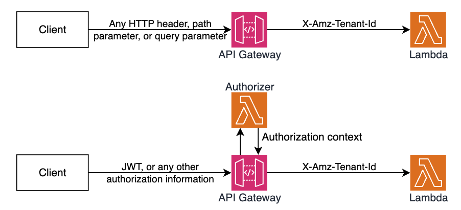
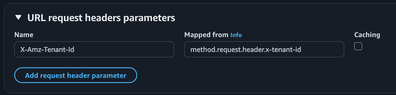
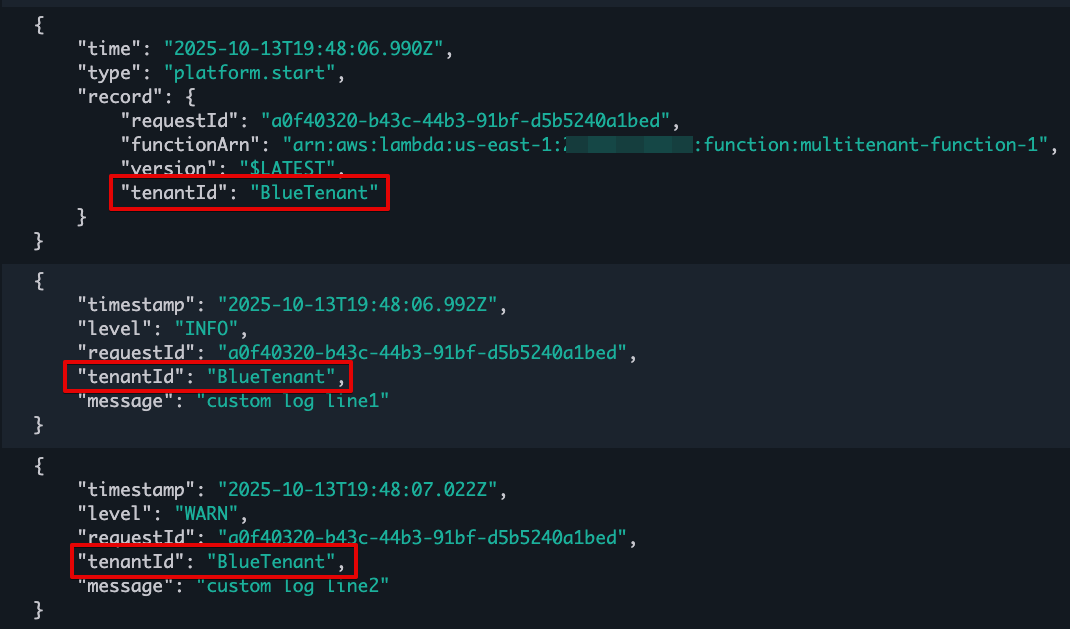


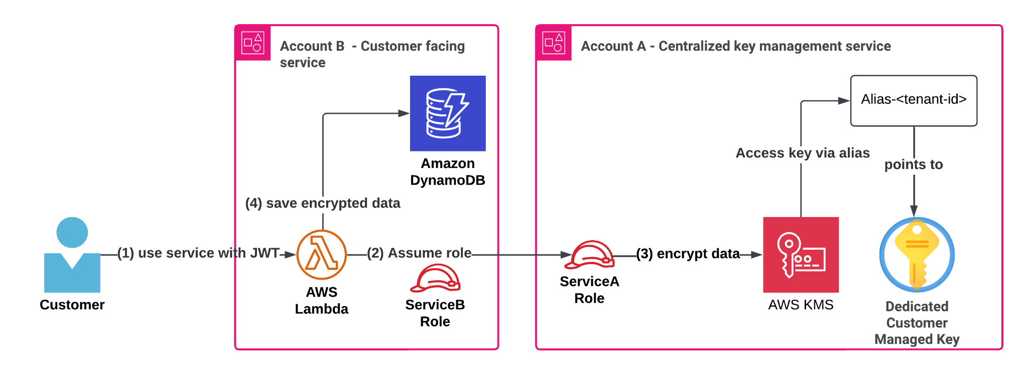


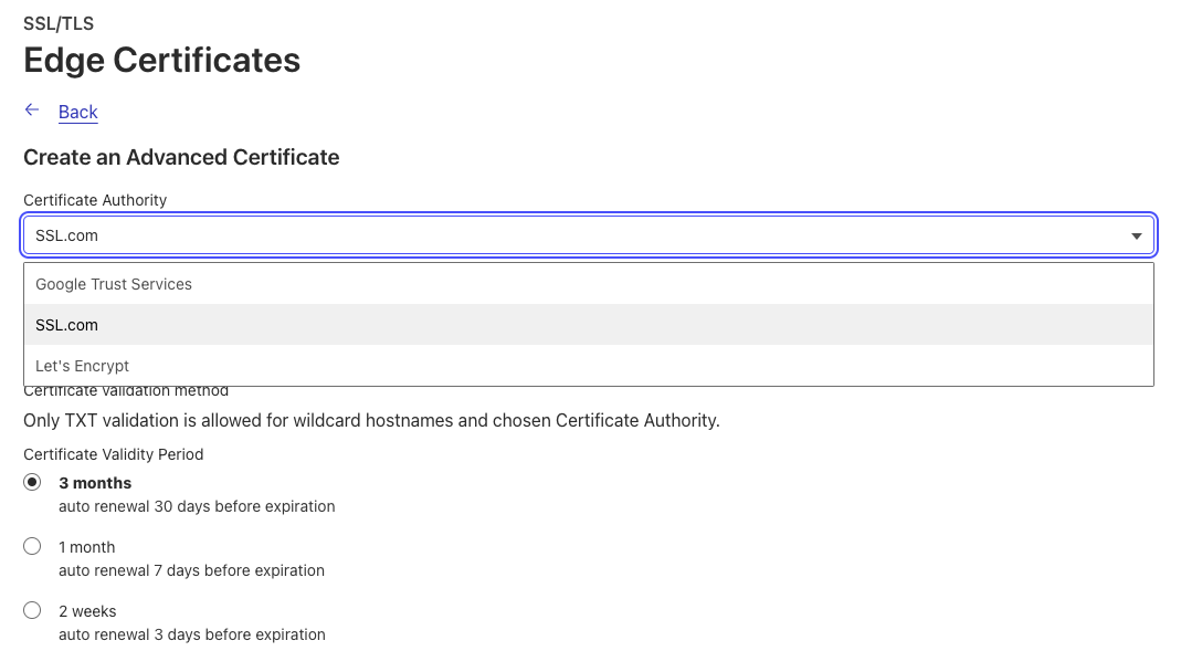
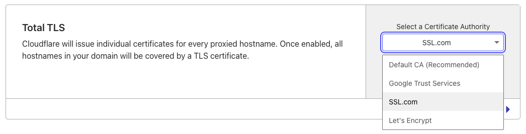


 Emmanuele Levi is a Solutions Architect in the Enterprise Software and SaaS team, based in London. Emanuele helps UK customers on their journey to refactor monolithic applications into modern microservices SaaS architectures. Emanuele is mainly interested in event-driven patterns and designs, especially when applied to analytics and AI, where he has expertise in the fraud-detection industry.
 Lorenzo Nicora is a Senior Streaming Solution Architect helping customers across EMEA. He has been building cloud-native, data-intensive systems for over 25 years, working across industries, in consultancies and product companies. He has leveraged open-source technologies extensively and contributed to several projects, including Apache Flink.
 Nicholas Tunney is a Senior Partner Solutions Architect for Worldwide Public Sector at AWS. He works with Global SI partners to develop architectures on AWS for clients in the government, nonprofit healthcare, utility, and education sectors. He is also a core member of the SaaS Technical Field Community where he gets to meet clients from all over the world who are building SaaS on AWS.
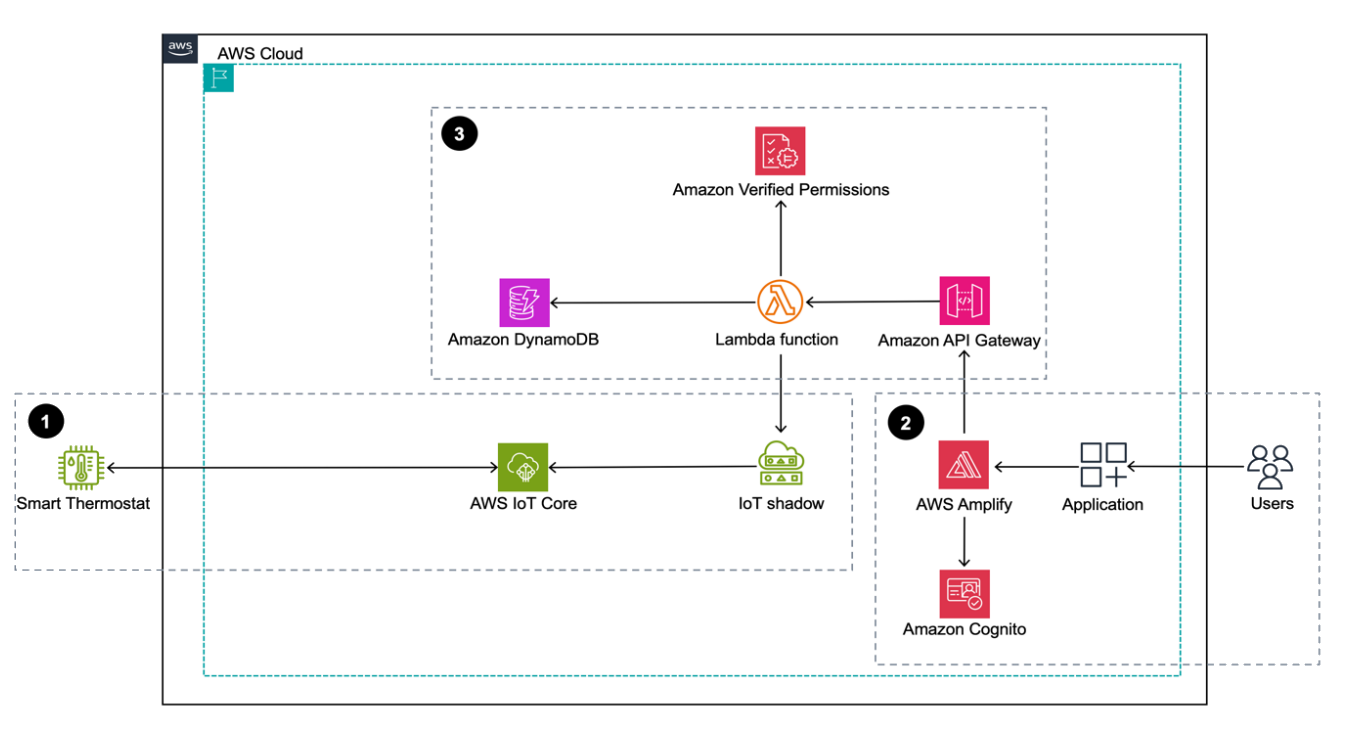
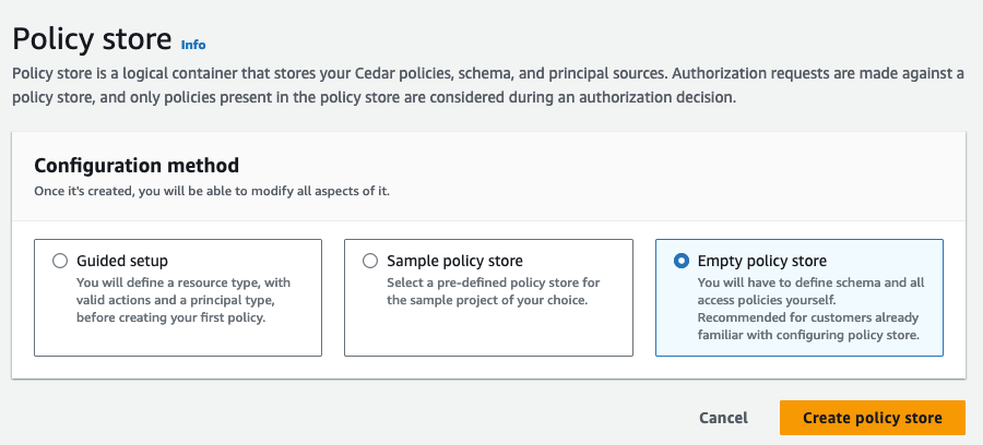


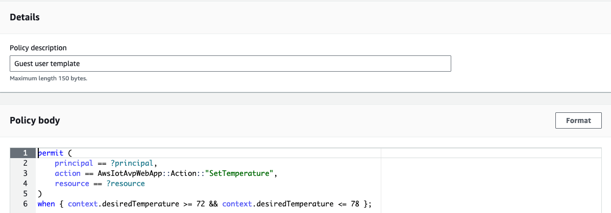


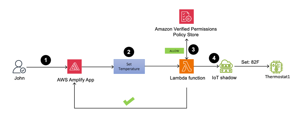
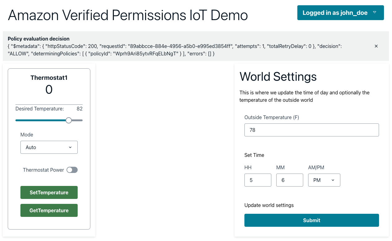
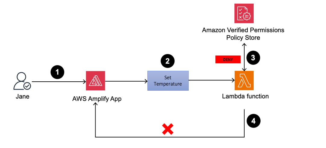


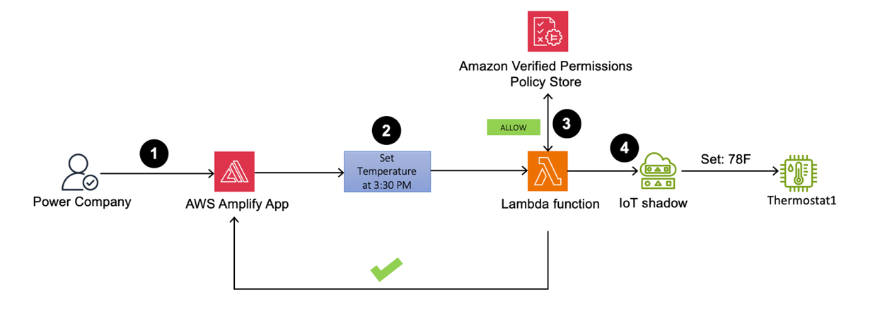


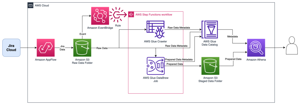
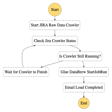


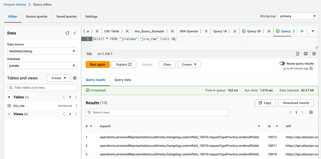


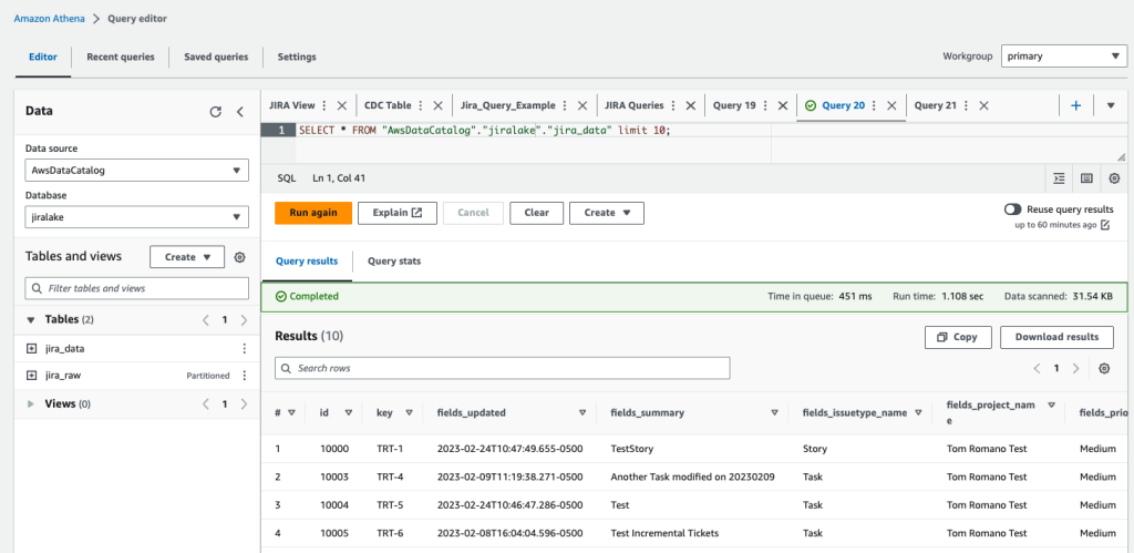
 Tom Romano is a Sr. Solutions Architect for AWS World Wide Public Sector from Tampa, FL, and assists GovTech and EdTech customers as they create new solutions that are cloud native, event driven, and serverless. He is an enthusiastic Python programmer for both application development and data analytics, and is an Analytics Specialist. In his free time, Tom flies remote control model airplanes and enjoys vacationing with his family around Florida and the Caribbean.
 Shane Thompson is a Sr. Solutions Architect based out of San Luis Obispo, California, working with AWS Startups. He works with customers who use AI/ML in their business model and is passionate about democratizing AI/ML so that all customers can benefit from it. In his free time, Shane loves to spend time with his family and travel around the world.