Two men have been convicted of hacking the taxi dispatch system at the JFK airport. This enabled them to reorder the taxis on the list; they charged taxi drivers $10 to cut the line.
This blog post is written by Jack Chen, Telco Solutions Architect, and Robert Belson, Developer Advocate.
AWS Wavelength embeds AWS compute and storage services within 5G networks, providing mobile edge computing infrastructure for developing, deploying, and scaling ultra-low-latency applications. AWS recently introduced support for Application Load Balancer (ALB) in AWS Wavelength zones. Although ALB addresses Layer-7 load balancing use cases, some low latency applications that get deployed in AWS Wavelength Zones rely on UDP-based protocols, such as QUIC, WebRTC, and SRT, which can’t be load-balanced by Layer-7 Load Balancers. In this post, we’ll review popular load-balancing patterns on AWS Wavelength, including a proposed architecture demonstrating how DNS-based load balancing can address customer requirements for load-balancing non-HTTP(s) traffic across multiple Amazon Elastic Compute Cloud (Amazon EC2) instances. This solution also builds a foundation for automatic scale-up and scale-down capabilities for workloads running in an AWS Wavelength Zone.
Load balancing use cases in AWS Wavelength
In the AWS Regions, customers looking to deploy highly-available edge applications often consider Amazon Elastic Load Balancing (Amazon ELB) as an approach to automatically distribute incoming application traffic across multiple targets in one or more Availability Zones (AZs). However, at the time of this publication, AWS-managed Network Load Balancer (NLB) isn’t supported in AWS Wavelength Zones and ALB is being rolled out to all AWS Wavelength Zones globally. As a result, this post will seek to document general architectural guidance for load balancing solutions on AWS Wavelength.
As one of the most prominent AWS Wavelength use cases, highly-immersive video streaming over UDP using protocols such as WebRTC at scale often require a load balancing solution to accommodate surges in traffic, either due to live events or general customer access patterns. These use cases, relying on Layer-4 traffic, can’t be load-balanced from a Layer-7 ALB. Instead, Layer-4 load balancing is needed.
To date, two infrastructure deployments involving Layer-4 load balancers are most often seen:
Amazon EC2-based deployments: Often the environment of choice for earlier-stage enterprises and ISVs, a fleet of EC2 instances will leverage a load balancer for high-throughput use cases, such as video streaming, data analytics, or Industrial IoT (IIoT) applications
Amazon EKS deployments: Customers looking to optimize performance and cost efficiency of their infrastructure can leverage containerized deployments at the edge to manage their AWS Wavelength Zone applications. In turn, external load balancers could be configured to point to exposed services via NodePort objects. Furthermore, a more popular choice might be to leverage the AWS Load Balancer Controller to provision an ALB when you create a Kubernetes Ingress.
Regardless of deployment type, the following design constraints must be considered:
Target registration: For load balancing solutions not managed by AWS, seamless solutions to load balancer target registration must be managed by the customer. As one potential solution, visit a recent HAProxyConf presentation, Practical Advice for Load Balancing at the Network Edge.
Edge Discovery: Although DNS records can be populated into Amazon Route 53 for each carrier-facing endpoint, DNS won’t deterministically route mobile clients to the most optimal mobile endpoint. When available, edge discovery services are required to most effectively route mobile clients to the lowest latency endpoint.
Cross-zone load balancing: Given the hub-and-spoke design of AWS Wavelength, customer-managed load balancers should proxy traffic only to that AWS Wavelength Zone.
Solution overview – Amazon EC2
In this solution, we’ll present a solution for a highly-available load balancing solution in a single AWS Wavelength Zone for an Amazon EC2-based deployment. In a separate post, we’ll cover the needed configurations for the AWS Load Balancer Controller in AWS Wavelength for Amazon Elastic Kubernetes Service (Amazon EKS) clusters.
The proposed solution introduces DNS-based load balancing, a technique to abstract away the complexity of intelligent load-balancing software and allow your Domain Name System (DNS) resolvers to distribute traffic (equally, or in a weighted distribution) to your set of endpoints.
Our solution leverages the weighted routing policy in Route 53 to resolve inbound DNS queries to multiple EC2 instances running within an AWS Wavelength zone. As EC2 instances for a given workload get deployed in an AWS Wavelength zone, Carrier IP addresses can be assigned to the network interfaces at launch.
Through this solution, Carrier IP addresses attached to AWS Wavelength instances are automatically added as DNS records for the customer-provided public hosted zone.
To determine how Route 53 responds to queries, given an arbitrary number of records of a public hosted zone, Route53 offers numerous routing policies:
Simple routing policy – In the event that you must route traffic to a single resource in an AWS Wavelength Zone, simple routing can be used. A single record can contain multiple IP addresses, but Route 53 returns the values in a random order to the client.
Weighted routing policy – To route traffic more deterministically using a set of proportions that you specify, this policy can be selected. For example, if you would like Carrier IP A to receive 50% of the traffic and Carrier IP B to receive 50% of the traffic, we’ll create two individual A records (one for each Carrier IP) with a weight of 50 and 50, respectively. Learn more about Route 53 routing policies by visiting the Route 53 Developer Guide.
The proposed solution leverages weighted routing policy in Route 53 DNS to route traffic to multiple EC2 instances running within an AWS Wavelength zone.
Reference architecture
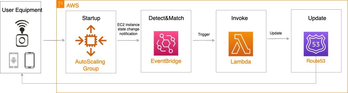
The following diagram illustrates the load-balancing component of the solution, where EC2 instances in an AWS Wavelength zone are assigned Carrier IP addresses. A weighted DNS record for a host (e.g., www.example.com) is updated with Carrier IP addresses.
When a device makes a DNS query, it will be returned to one of the Carrier IP addresses associated with the given domain name. With a large number of devices, we expect a fair distribution of load across all EC2 instances in the resource pool. Given the highly ephemeral mobile edge environments, it’s likely that Carrier IPs could frequently be allocated to accommodate a workload and released shortly thereafter. However, this unpredictable behavior could yield stale DNS records, resulting in a “blackhole” – routes to endpoints that no longer exist.
Time-To-Live (TTL) is a DNS attribute that specifies the amount of time, in seconds, that you want DNS recursive resolvers to cache information about this record.
In our example, we should set to 30 seconds to force DNS resolvers to retrieve the latest records from the authoritative nameservers and minimize stale DNS responses. However, a lower TTL has a direct impact on cost, as a result of increased number of calls from recursive resolvers to Route53 to constantly retrieve the latest records.
The core components of the solution are as follows:
AWS Auto Scaling Group– a collection of EC2 instances logically grouped together for the purpose of automatic scaling.
Alongside the services above in the AWS Wavelength Zone, the following services are also leveraged in the AWS Region:
AWS Lambda – a serverless event-driven function that makes API calls to the Route 53 service to update DNS records.
Amazon EventBridge– a serverless event bus that reacts to EC2 instance lifecycle events and invokes the Lambda function to make DNS updates.
Route 53– cloud DNS service with a domain record pointing to AWS Wavelength-hosted resources.
In this post, we intentionally leave the specific load balancing software solution up to the customer. Customers can leverage various popular load balancers available on the AWS Marketplace, such as HAProxy and NGINX. To focus our solution on the auto-registration of DNS records to create functional load balancing, this solution is designed to support stateless workloads only. To support stateful workloads, sticky sessions – a process in which routes requests to the same target in a target group – must be configured by the underlying load balancer solution and are outside of the scope of what DNS can provide natively.
Automation overview
Using the aforementioned components, we can implement the following workflow automation:
Amazon CloudWatchalarm can trigger the Auto Scaling group Scale out or Scale in event by adding or removing EC2 instances. Eventbridge will detect the EC2 instance state change event and invoke the Lambda function. This function will update the DNS record in Route53 by either adding (scale out) or deleting (scale in) a weighted A record associated with the EC2 instance changing state.
Configuration of the automatic auto scaling policy is out of the scope of this post. There are many auto scaling triggers that you can consider using, based on predefined and custom metrics such as memory utilization. For the demo purposes, we will be leveraging manual auto scaling.
Amazon Virtual Private Cloud (Amazon VPC), subnets, Carrier Gateway, and Route Tables are foundational building blocks for AWS-based networking infrastructure. In our deployment, we are creating a new VPC, one subnet in an AWS Wavelength zone of your choice, a Carrier Gateway, and updating the route table for this subnet to point the default route to the Carrier Gateway.
Deployment prerequisites
The following are prerequisites to deploy the described solution in your account:
Access to an AWS Wavelength zone. If your account is not allow-listed to use AWS Wavelength zones, then opt-in to AWS Wavelength zones here.
Public DNS Hosted Zone hosted in Route 53. You must have access to a registered public domain to deploy this solution. The zone for this domain should be hosted in the same account where you plan to deploy AWS Wavelength workloads. If you don’t have a public domain, then you can register a new one. Note that there will be a service charge for the domain registration.
Amazon S3 bucket. For the Lambda function that updates DNS records in Route 53, store the source code as a .zip file in an Amazon S3 bucket.
Amazon EC2 Key pair. You can use an existing Key pair for the deployment. If you don’t have a KeyPair in the region where you plan to deploy this solution, then create one by following these instructions.
4G or 5G-connected device. Although the infrastructure can be deployed independent of the underlying connected devices, testing the connectivity will require a mobile device on one of the Wavelength partner’s networks. View the complete list of Telecommunications providers and Wavelength Zone locations to learn more.
Conclusion
In this post, we demonstrated how to implement DNS-based load balancing for workloads running in an AWS Wavelength zone. We deployed the solution that used the EventBridge Rule and the Lambda function to update DNS records hosted by Route53. If you want to learn more about AWS Wavelength, subscribe to AWS Compute Blog channel here.
A critical code-execution vulnerability in Microsoft Windows was patched in September. It seems that researchers just realized how serious it was (and is):
Like EternalBlue, CVE-2022-37958, as the latest vulnerability is tracked, allows attackers to execute malicious code with no authentication required. Also, like EternalBlue, it’s wormable, meaning that a single exploit can trigger a chain reaction of self-replicating follow-on exploits on other vulnerable systems. The wormability of EternalBlue allowed WannaCry and several other attacks to spread across the world in a matter of minutes with no user interaction required.
But unlike EternalBlue, which could be exploited when using only the SMB, or server message block, a protocol for file and printer sharing and similar network activities, this latest vulnerability is present in a much broader range of network protocols, giving attackers more flexibility than they had when exploiting the older vulnerability.
[…]
Microsoft fixed CVE-2022-37958 in September during its monthly Patch Tuesday rollout of security fixes. At the time, however, Microsoft researchers believed the vulnerability allowed only the disclosure of potentially sensitive information. As such, Microsoft gave the vulnerability a designation of “important.” In the routine course of analyzing vulnerabilities after they’re patched, Palmiotti discovered it allowed for remote code execution in much the way EternalBlue did. Last week, Microsoft revised the designation to critical and gave it a severity rating of 8.1, the same given to EternalBlue.
“You still have a lot of soldiers bringing cellphones to the frontline who want to talk to their families and they are either being intercepted as they go through a Ukrainian telecommunications provider or intercepted over the air,” said Alperovitch. “That doesn’t pose too much difficulty for the Ukrainian security services.”
[…]
“Security has always been a mess, both in the army and among defence officials,” the source said. “For example, in 2013 they tried to get all the staff at the ministry of defence to replace our iPhones with Russian-made Yoto smartphones.
“But everyone just kept using the iPhone as a second mobile because it was much better. We would just keep the iPhone in the car’s glove compartment for when we got back from work. In the end, the ministry gave up and stopped caring. If the top doesn’t take security very seriously, how can you expect any discipline in the regular army?”
This isn’t a new problem and it isn’t a Russian problem. Here’s a more general article on the problem from 2020.
Mandiant is reporting on a trojaned Windows installer that targets Ukrainian users. The installer was left on various torrent sites, presumably ensnaring people downloading pirated copies of the operating system:
Mandiant uncovered a socially engineered supply chain operation focused on Ukrainian government entities that leveraged trojanized ISO files masquerading as legitimate Windows 10 Operating System installers. The trojanized ISOs were hosted on Ukrainian- and Russian-language torrent file sharing sites. Upon installation of the compromised software, the malware gathers information on the compromised system and exfiltrates it. At a subset of victims, additional tools are deployed to enable further intelligence gathering. In some instances, we discovered additional payloads that were likely deployed following initial reconnaissance including the STOWAWAY, BEACON, and SPAREPART backdoors.
One obvious solution would be for Microsoft to give the Ukrainians Windows licenses, so they don’t have to get their software from sketchy torrent sites.
The Ukrainian army has released an instructional video explaining how Russian soldiers should surrender to a drone:
“Seeing the drone in the field of view, make eye contact with it,” the video instructs. Soldiers should then raise their arms and signal they’re ready to follow.
After that the drone will move up and down a few meters, before heading off at walking pace in the direction of the nearest representatives of Ukraine’s army, it says.
The video also warns that the drone’s battery may run low, in which case it will head back to base and the soldiers should stay put and await a fresh one.
That one, too, should be met with eye contact and arms raised, it says.
How do you prevent the most common merge conflicts when your team is working on a Serverless application? How do you make sure that your team stays productive and avoids large merge issues while trying to update the same crucial files simultaneously? –The answer to both questions is code organization! You can use cfn-include and swagger-cli to organize, collaborate, and maintain a large serverless application as well as support a large or decentralized development team.
Real life inspiration
WRAP Technologies Inc. (WRAP) creates advanced technologies for the protection and security of public safety. Their WRAP Reality product allows law enforcement agencies to train their officers using virtual reality-based scenarios.
Too many cooks in the kitchen
When multiple developers collaborate on a serverless architecture built with AWS CloudFormation, and its extensions such as the AWS Serverless Application Model (SAM), the nature of specifying resources in both the template.yaml and the optional OpenAPI.yaml specification for Amazon API Gateway leads to merge conflicts, such as the one demonstrated in the following figure where two developers are adding different API endpoints at the same time. These conflicts detract from the developer’s time and agility. Furthermore, navigating and maintaining the long template files required for a larger serverless architecture slows development as the developer scans large files to find a particular resource definition.
Figure 1. The frustrating merge conflicts.
By refactoring and organizing the CloudFormation and OpenAPI files, your development team can realize several benefits:
Improve developer efficiency by decomposing large, hard-to-manage files into a series of well-organized and single-purpose files.
Enhance developer productivity by allowing each developer to have ownership of their own code, thereby reducing the need to coordinate merges with teammates.
Eliminate potential merge issues for files that generate the most conflicts during the development of a typical Serverless API application.
Rapid development
WRAP partnered with AWS to develop and host the backend for their new officer training management platform. This entirely new platform was developed, completed, and available for use in a matter of months. Moreover, it’s a collaboration of developers spread across multiple teams worldwide, all contributing to the same code base. By instituting the norms and techniques of this post, WRAP created a large and maintainable serverless application with minimal developer code collisions.
Development of the WRAP Reality training management system was accomplished using CloudFormation for defining Infrastructure as Code (IaC), and an Amazon API Gateway OpenAPI specification for defining API contracts. The development team for the WRAP Reality training management service leveraged agile development for expediency, including the GitHub Flow branching strategy. However, since project contributors were not co-located, several considerations were put in place to make sure of consistency and speed of code development:
The API specifications and contracts were defined in OpenAPI (Swagger) specifications early in the development process, clearly defining the project structure up front, and allowing developers to independently build infrastructure components.
The two code assets central to the entire project – the CloudFormation template and the OpenAPI Specification – were decomposed into small, easily manageable components. This enabled components to be organized in a way that enhanced development productivity and practically eliminated the inevitable merge conflicts that come with large source code files that are being modified on a daily basis.
The development process was accelerated by utilizing OpenAPI integrations with AWS Services, as well as techniques for managing the OpenAPI specification and Cloudformation Template files.
Sample project
To demonstrate these techniques, we’ll explore the following sample project comprised of API endpoints for “widget” management, available on GitHub. This project provides the following end points:
/widget PUT: Creation of a new widget
/widget GET: Retrieval of a new widget
/reports/color GET: Retrieval of a set of widgets based on the widget color
/reports/filterpage GET: Retrieval of widgets based on specified filters
The overall architecture of the application is shown in the following diagram:
Figure 2. Architecture Diagram
The application comprises:
Amazon API Gateway is a fully-managed service that makes it easy for developers to create, publish, maintain, monitor, and secure APIs at any scale. In this example, API Gateway serves as the web service for the API endpoints. The mapping of data to and from the API endpoints to the Lambda functions is formally defined by an OpenAPI specification file.
AWS Lambda is a serverless compute service that lets you run code without provisioning or managing servers, creating workload-aware cluster scaling logic, maintaining event integrations, or managing runtimes. In this example, four Lambda functions are used to service each of the four API calls.
Amazon DynamoDB is a key-value and document database that delivers single-digit millisecond performance at any scale. DynamoDB is used as a persistent data store for widgets and associated properties.
OpenAPI and AWS service integration
When using API Gateway, developers have the option of using proxy Lambda integrations, or formally defining the API interface in an OpenAPI yaml file. The OpenAPI specification can be leveraged to document the API prior to development, and the example/mock features of the OpenAPI specification facilitates concurrent development by quickly establishing a working infrastructure to build upon. Furthermore, API documentation can be automatically generated from the OpenAPI specification.
As the number of endpoints increases, the OpenAPI specification file can grow in size, reaching thousands of lines of code that must be updated and maintained regularly by multiple developers. To aid in management and usability, the OpenAPI file can be decomposed into separate files for endpoints, responses, fields, and schemas.
Start with a “skeleton” file as an entry point for the OpenAPI definition, and then add a separate file for the definition of each endpoint or construct. For example, the sample project entry point is api/apiSkeleton.yaml, which contains the global definitions and effectively defines a simple list of endpoints and the reference ($ref) file path to each endpoint’s definition.
Diving into a file referenced by an endpoint, we see that it contains all of the specification details for that endpoint. Looking at the reportsColor.yaml file reveals the full endpoint specification for /reports/color:
get:
  description: Get widgets by color
  parameters:
    - in: path
      $ref: '../../requestParameters/color.yaml'
  responses:
    200:
      description: Get All the Widgets of a color
      content:
        application/json:
          schema:
            $ref: '../../schemas/widgetList.yaml'
    . . .
In turn, this endpoint specification can include further references to yaml files defining common parameters, schemas, and even full gateway responses. For example, color.yaml defines the color path variable:
  type: string
    description: "The widget's color"
    example: "Red"
To paraphrase a common catch phrase, “With a great many files, comes a great responsibility for organization.” To this end, we offer the following organizational structure as a start. Place all of the related API specifications in an “api” subfolder of your project. Have child subfolders for field, metadata, and gateway response definition files. Then, create child subfolder trees for each branch of your endpoints that mirror the endpoint paths. This will result in a highly-organized directory structure, as seen in the sample project:
We still need a consolidated single OpenAPI file to provide to CloudFormation during deployment to AWS. Therefore, the multiple files are combined and validated using the swagger-cli bundle command, resulting in a single file for deployment. The bundle command must be executed before a CloudFormation build. This command can also be included as a shortcut in the Makefile as the “buildOpenApi” command:
Once compiled, api/api.yaml is then used normally for API Gateway integrations and as a Postman API Collection import. As api/api.yaml is dynamically compiled, it’s included in .gitignore and not checked in to AWS CodeCommit.
cfn-include and nested stacks
The CloudFormation template that defines the infrastructure for even a simple service can grow to considerable length, perhaps thousands of lines. This presents challenges from a support and continued development perspective, as specific code locations become difficult to find and merge conflicts become commonplace.
CloudFormation Nested Stacks are a method of breaking a large CloudFormation template into separate templates. When there are clear delineations between groups of resources in a stack breaking it into separate nested stacks makes sense. There is also a 500 resource limit in a single CloudFormation stack and in order to go above that nested or separate stacks are necessary. Depending on the complexity of the architecture and frequency of updates however, the Nested Stacks can also become large. Furthermore, in a serverless architecture, the logical separation of architecture layers into separate stacks may not be direct, for example when a Lambda function is triggered by an event sent to an EventBridge event bus, then that Lambda function sends a different event back to the same event bus.
In these cases, CloudFormation templates can be decomposed to further leverage cfn-include . With this technique, the top-level CloudFormation template becomes a skeleton file which contains the stack parameters, global specifications, a list of resource names without properties, and the outputs. The properties of each resource are contained in separate files, referenced by an ‘include’ directive. CloudFormation template organization
To organize your CloudFormation template, deconstruct the template into one-file-per-resource, with one main “skeleton” file as the main entry point. This skeleton file contains the full parameters, global section, conditions, and output specification. The resources are specified by resource name in this skeleton file, and then an ‘include’ directive points to the file that contains the body of the resource declaration. See the following example of the main skeleton file with two resources:
This approach has the benefit of breaking the CloudFormation template into multiple small files, while still maintaining a top-level holistic view. The resource definitions, which normally comprise the majority of the content and can cause merge conflicts, are moved out of the main template.
For organization, you can create a directory in your project to contain the CloudFormation scripts. This directory also contains the entry-point skeleton file. Create further sub-folders for resources, and then further folders by resource type and architecture. We found that placing applicable AWS Identity and Access Management (IAM) role resource definitions in the same folder with the applied resource facilitated easier navigation. For example:
The files must be reconstituted to a single template.yaml for CloudFormation build and deployment. This is accomplished with the cfn-include command. A convenience command can optionally be included in the Makefile.
As the final template.yaml file is dynamically compiled, it’s included in .gitignore and not checked in to CodeCommit.
Conclusion
This post demonstrates techniques used by WRAP and AWS to rapidly develop and maintain key files in an Serverless architecture. The techniques discussed in this post allowed the WRAP and AWS team to do the following:
Improve developer efficiency by decomposing large, hard-to-manage files into a series of well-organized and single purpose files.
Enhance developer productivity by allowing each developer to have ownership of their own piece of the code without having to coordinate with teammates.
Eliminate potential merge issues on the files that typically generate the most conflicts during the development of a typical Serverless API application.
Applying these techniques was one of the key factors in the rapid development of the WRAP Reality training framework.
The most recent iPhone update—to version 16.1.2—patches a zero-day vulnerability that “may have been actively exploited against versions of iOS released before iOS 15.1.”
Apple said security researchers at Google’s Threat Analysis Group, which investigates nation state-backed spyware, hacking and cyberattacks, discovered and reported the WebKit bug.
WebKit bugs are often exploited when a person visits a malicious domain in their browser (or via the in-app browser). It’s not uncommon for bad actors to find vulnerabilities that target WebKit as a way to break into the device’s operating system and the user’s private data. WebKit bugs can be “chained” to other vulnerabilities to break through multiple layers of a device’s defenses.
Security researchers found a software bug in the KmsdBot cryptomining botnet:
With no error-checking built in, sending KmsdBot a malformed command—like its controllers did one day while Akamai was watching—created a panic crash with an “index out of range” error. Because there’s no persistence, the bot stays down, and malicious agents would need to reinfect a machine and rebuild the bot’s functions. It is, as Akamai notes, “a nice story” and “a strong example of the fickle nature of technology.”
The idea was to bring together people from a variety of disciplines who are all thinking about different aspects of democracy, less from a “what we need to do today” perspective and more from a blue-sky future perspective. My remit to the participants was this:
The idea is to start from scratch, to pretend we’re forming a new country and don’t have any precedent to deal with. And that we don’t have any unique interests to perturb our thinking. The modern representative democracy was the best form of government mid-eighteenth century politicians technology could invent. The twenty-first century is a very different place technically, scientifically, and philosophically. What could democracy look like if it were reinvented today? Would it even be democracy—what comes after democracy?
Some questions to think about:
Representative democracies were built under the assumption that travel and communications were difficult. Does it still make sense to organize our representative units by geography? Or to send representatives far away to create laws in our name? Is there a better way for people to choose collective representatives?
Indeed, the very idea of representative government is due to technological limitations. If an AI system could find the optimal solution for balancing every voter’s preferences, would it still make sense to have representatives—or should we vote for ideas and goals instead?
With today’s technology, we can vote anywhere and any time. How should we organize the temporal pattern of voting—and of other forms of participation?
Starting from scratch, what is today’s ideal government structure? Does it make sense to have a singular leader “in charge” of everything? How should we constrain power—is there something better than the legislative/judicial/executive set of checks and balances?
The size of contemporary political units ranges from a few people in a room to vast nation-states and alliances. Within one country, what might the smaller units be—and how do they relate to one another?
Who has a voice in the government? What does “citizen” mean? What about children? Animals? Future people (and animals)? Corporations? The land?
And much more: What about the justice system? Is the twelfth-century jury form still relevant? How do we define fairness? Limit financial and military power? Keep our system robust to psychological manipulation?
My perspective, of course, is security. I want to create a system that is resilient against hacking: one that can evolve as both technologies and threats evolve.
The format was one that I have used before. Forty-eight people meet over two days. There are four ninety-minute panels per day, with six people on each. Everyone speaks for ten minutes, and the rest of the time is devoted to questions and comments. Ten minutes means that no one gets bogged down in jargon or details. Long breaks between sessions and evening dinners allow people to talk more informally. The result is a very dense, idea-rich environment that I find extremely valuable.
It was amazing event. Everyone participated. Everyone was interesting. (Details of the event—emerging themes, notes from the speakers—are in the comments.) It’s a week later and I am still buzzing with ideas. I hope this is only the first of an ongoing series of similar workshops.
This blog post is written by Eric Vasquez, Specialist Hybrid Edge Solutions Architect, and Paul Scherer, Senior Network Service Tech.
Overview
AWS Outposts brings managed, monitored AWS infrastructure, compute, and storage to your on-premises environment. It provides the same AWS APIs, and console experience you would get within the AWS Region to which the Outpost is homed to. You may already have an Outposts rack. An Outpost can consist of one or more racks creating a pool of consumable resources as a single logical Outpost. In this post, we will introduce you to an Aggregation, Core, Edge (ACE) rack.
Depending on your familiarity with the Outpost family, you might have already heard about an ACE rack. An ACE rack serves as an aggregation point for multi-rack Outpost deployments. ACE racks reduce the physical networking port requirements as well as the logical interfaces needed, while allowing for connectivity between multiple racks in your logical Outpost. ACE racks are recommended for customers with planned deployments beyond three racks excluding the ACE rack itself.
We recommend that all customers leverage an ACE rack if planning expansions beyond three racks in the long-term, even if the initial deployment is a single rack. An ACE rack contains four routers, and these routers can connect to either two or four customer upstream devices. For the best redundancy, reliability, and resiliency, we recommend deploying an ACE rack to four upstream customer devices.
ACE racks support 10G, 40G, and 100G connections to a customer network. However, 100G connections between each ACE router to a customer device are recommended.
Outpost extension from region and ACE rack deployment in a 15 rack Outpost configuration
Each Outposts rack comes standard with redundant Outpost networking devices, power supplies, and two top-of-rack patch panels which serve as demarcation points between the Outpost rack and your customer networking device (CND). For the remainder of this post, we’ll refer to the Outpost Networking Devices as OND and customer switches/routers as CND. The Outpost rack ONDs form Border Gateway Protocol (BGP) neighbor relationships with either your CND or the ACE rack using point-to-point (P2P) Virtual LAN (VLAN) interfaces.
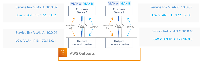
For Outposts installation without an ACE rack, each Outposts OND connects to your LAN using single-mode or multi-mode fiber with LC connectors supporting 1G, 10G, 40G, or 100G connectivity. We provide flexibility for the CNDs and allow either Layer 2 or Layer 3 devices, including firewalls. Each OND uses a single LACP port channel that carries 2 VLAN point-to-points virtual interfaced (VIF)to establish 2 BGP relationships over the port channel to your upstream CND and aggregate total bandwidth. This results in each Outpost rack requiring a minimum of two physical uplinks, but as a general best practice we recommend two-per-device for a total of four uplinks, along with two LACP port channels and 4 VLAN to establish point-to-points (P2P) BGP peering’s. Note that the IP’s used in the following diagram are just examples.
Outpost Service link and Local Gateway VLAN
As we continue to expand rack deployments, so will the number of physical uplinks and VLAN interfaces required for the added OND to a CND. When we introduce the ACE rack, the OND is no longer attached to your CND. Instead, it goes directly to ACE devices, which provide at least one uplink to your network switch/router. In this topology, AWS owns the VLAN interface allocation and configuration between compute rack OND and the ACE routers.
Let’s cover the potential downsides to a multi-rack installation without an ACE rack. In this case, we have a three-rack Outpost deployment, with one uplink (two per rack) from each rack OND to the CND. This would require you to provide: six physical ports on your devices, six fiber cables,12 VLAN VIFs, 12 P2P subnets potentially exhausting 24 ips, and six port channels.
In comparison to a three-rack install that sits behind an ACE rack, you provide fewer physical network ports on your devices, fewer fiber cabling uplinks, fewer VLAN VIFs, fewer port channels, and fewer P2P’s. Each ACE router will have its own LACP port channel with 2x VLAN VIFs in each channel (the same as an Outposts Networking Devices (OND) <> Customer connection). The following table highlights the advantages in using an ACE rack when running a multi-rack Outpost, which becomes more desirable as you continue to scale.
2-Rack Outpost
Installation
3-Rack Outpost
Installation
4-Rack Outpost
Installation
Requirement
Without ACE
With ACE
Without ACE
With ACE
Without ACE
With ACE
Physical Ports
4
4
6
4
8
4
Fiber Cables
4
4
6
4
8
4
LACP Port Channels
4
4
6
4
8
4
VLAN VIFs
8
8
12
8
16
8
P2P Subnets
8
8
12
8
16
8
ACE VS Non-ACE Rack Components Comparison
Furthermore, you should consider the additional weight, and power requirements that an ACE rack introduces when planning for multi-rack deployments. In addition to initial kVA requirements for the Outpost racks you must account for the resources required for an ACE rack. An ACE rack consumes up to 10kVA of power and weighs up to 705 lbs. Carefully planning additional capacity for these resources with your AWS account team will be critical for a successful deployment.
Similar to an Outpost rack, an ACE rack deployment is monitored by AWS. The rack provides telemetry data transmitted over a set of VPN tunnels back to the anchor points in the Region to which the Outpost is homed. This allows AWS to monitor the rack for hardware failures, performance degradation, and other alarm conditions including Links, Interfaces going down, and BGP drops.
As part of the Outpost ordering process, AWS will work closely with you to determine the location for install, power availability on-site, and the network configuration of both the Outposts rack and ACE rack. This includes BGP configuration, and the Customer Owned IP Address (CoIP), which is the pool of IP addresses for route advertisements back to your CND. The COIP pool allows resources inside your Outpost rack to communicate with on-premises resources and vice-versa. Another connectivity option would be the Direct VPC Routing (DVR) where we advertise VPC subnets associated with your LGW to your on-premises networks. Outposts uses a networking connectivity back to the Region for management purposes called the service link (SL). The SL is an encrypted set of VPN connections used whenever the Outpost communicates with your chosen home Region.
Conclusion
This post addresses the most common questions surrounding ACE racks, how an ACE rack can be deployed, and why an ACE rack would be leveraged for a multi-Outpost rack deployment. In this post, we demonstrated how an ACE rack serves as a consolidation point in your on-premises environment, making multi-rack deployments scalable, while reducing complexity and physical port allocation for connectivity between an Outpost and your LAN. In addition, we described how you can get this process started. If you want to learn more about Outposts fundamentals and how you can build your applications with AWS services using Outposts for hybrid cloud deployments you can learn more check out the Outposts user guide.
Write an essay in the style of Bruce Schneier on how ChatGPT will affect cybersecurity.
As with any new technology, the development and deployment of ChatGPT is likely to have a significant impact on the field of cybersecurity. In many ways, ChatGPT and other AI technologies hold great promise for improving the ability of organizations and individuals to defend against cyber threats. At the same time, however, the use of these technologies also raises important questions and concerns about the potential risks and challenges they may pose.
One of the key ways in which ChatGPT is likely to affect cybersecurity is by enabling organizations to more quickly and accurately identify potential security threats. With its ability to analyze vast amounts of data and identify patterns and trends that might be difficult for humans to spot, ChatGPT could be a valuable tool for detecting and responding to cyberattacks. This could be especially useful in the case of complex, coordinated attacks that might otherwise be difficult to identify and defend against.
Another potential benefit of ChatGPT in the realm of cybersecurity is its ability to improve communication and coordination among different organizations and agencies. By enabling these groups to more easily share information and work together to defend against cyber threats, ChatGPT could help to make the overall cybersecurity landscape more effective and efficient. This could be especially important in the case of large-scale attacks that require a coordinated response from multiple organizations.
Of course, as with any new technology, there are also potential risks and challenges associated with the use of ChatGPT in the field of cybersecurity. One key concern is the potential for ChatGPT to be used by malicious actors to conduct cyberattacks. By automating the process of planning and executing attacks, ChatGPT could make it easier for attackers to carry out sophisticated, coordinated attacks at a much faster pace than would be possible without AI. This could potentially make it more difficult for organizations and individuals to defend against such attacks.
Another potential risk is the possibility that ChatGPT could be used to create fake news or propaganda, which could be used to spread misinformation or confusion. In the context of cybersecurity, the spread of false information could potentially lead to confusion and panic, making it more difficult for organizations and individuals to respond effectively to cyber threats. Additionally, the use of ChatGPT to create fake news or propaganda could also undermine trust in information and communications systems, potentially undermining the overall security of these systems.
Overall, the development and deployment of ChatGPT is likely to have a significant impact on the field of cybersecurity. While ChatGPT and other AI technologies hold great promise for improving the ability of organizations and individuals to defend against cyber threats, it is important to carefully consider the potential risks and challenges they may pose, and to take appropriate measures to mitigate these risks. This may include implementing strict security protocols and safeguards to prevent unauthorized access to ChatGPT and other AI systems, as well as ongoing monitoring and evaluation to ensure that these technologies are being used in a safe and responsible manner.
Not bad. I don’t think I can retire, but I probably can go on vacation for a few days. And, of course, it’s going to get better…a lot better…and probably sooner than we expect. This is a big deal.
Many organizations require durable automated code delivery for their applications. They leverage multi-account continuous integration/continuous deployment (CI/CD) pipelines to deploy code and run automated tests in multiple environments before deploying to Production. In cases where the testing strategy is release specific, you must update the pipeline before every release. Traditional pipeline stages are predefined and static in nature, and once the pipeline stages are defined it’s hard to update them. In this post, we present a configuration driven dynamic CI/CD solution per repository. The pipeline state is maintained and governed by configurations stored in Amazon DynamoDB. This gives you the advantage of automatically customizing the pipeline for every release based on the testing requirements.
The following diagram illustrates the solution architecture:
Figure 1: Architecture Diagram
Users insert/update/delete entry in the DynamoDB table.
The Step Function Trigger Lambda is invoked on all modifications.
The Step Function Trigger Lambda evaluates the incoming event and does the following:
On insert and update, triggers the Step Function.
On delete, finds the appropriate CloudFormation stack and deletes it.
Steps in the Step Function are as follows:
Collect Information (Pass State) – Filters the relevant information from the event, such as repositoryName and referenceName.
Get Mapping Information (Backed by CodeCommit event filter Lambda) – Retrieves the mapping information from the Pipeline config stored in the DynamoDB.
Deployment Configuration Exist? (Choice State) – If the StatusCode == 200, then the DynamoDB entry is found, and Initiate CloudFormation Stack step is invoked, or else StepFunction exits with Successful.
Initiate CloudFormation Stack (Backed by stack create Lambda) – Constructs the CloudFormation parameters and creates/updates the dynamic pipeline based on the configuration stored in the DynamoDB via CloudFormation.
Code deliverables
The code deliverables include the following:
AWS CDK app – The AWS CDK app contains the code for all the Lambdas, Step Functions, and CloudFormation templates.
sample-application-repo – This directory contains the sample application repository used for deployment.
automated-tests-repo– This directory contains the sample automated tests repository for testing the sample repo.
Follow the README to deploy the solution to your main CI/CD account. Upon successful deployment, the following resources should be created in the CI/CD account:
A DynamoDB table
Step Function
Lambda Functions
Navigate to the Amazon Simple Storage Service (Amazon S3) console in your main CI/CD account and search for a bucket with the name: cloudformation-template-bucket-<AWS_ACCOUNT_ID>. You should see two CloudFormation templates (templates/codepipeline.yaml and templates/childaccount.yaml) uploaded to this bucket.
Run the childaccount.yaml in every target CI/CD account (Alpha, Beta, Gamma, and Prod) by going to the CloudFormation Console. Provide the main CI/CD account number as the “CentralAwsAccountId” parameter, and execute.
Upon successful creation of Stack, two roles will be created in the Child Accounts:
ChildAccountFormationRole
ChildAccountDeployerRole
Pipeline configuration
Make an entry into devops-pipeline-table-info for the Repository name and branch combination. A sample entry can be found in sample-entry.json.
The pipeline is highly configurable, and everything can be configured through the DynamoDB entry.
The following are the top-level keys:
RepoName: Name of the repository for which AWS CodePipeline is configured. RepoTag: Name of the branch used in CodePipeline. BuildImage: Build image used for application AWS CodeBuild project. BuildSpecFile: Buildspec file used in the application CodeBuild project. DeploymentConfigurations: This key holds the deployment configurations for the pipeline. Under this key are the environment specific configurations. In our case, we’ve named our environments Alpha, Beta, Gamma, and Prod. You can configure to any name you like, but make sure that the entries in json are the same as in the codepipeline.yaml CloudFormation template. This is because there is a 1:1 mapping between them. Sub-level keys under DeploymentConfigurations are as follows:
EnvironmentName. This is the top-level key for environment specific configuration. In our case, it’s Alpha, Beta, Gamma, and Prod. Sub level keys under this are:
<Env>AwsAccountId: AWS account ID of the target environment.
Deploy<Env>: A key specifying whether or not the artifact should be deployed to this environment. Based on its value, the CodePipeline will have a deployment stage to this environment.
ManualApproval<Env>: Key representing whether or not manual approval is required before deployment. Enter your email or set to false.
Tests: Once again, this is a top-level key with sub-level keys. This key holds the test related information to be run on specific environments. Each test based on whether or not it will be run will add an additional step to the CodePipeline. The tests’ related information is also configurable with the ability to specify the test repository, branch name, buildspec file, and build image for testing the CodeBuild project.
Execute
Make an entry into the devops-pipeline-table-info DynamoDB table in the main CI/CD account. A sample entry can be found in sample-entry.json. Make sure to replace the configuration values with appropriate values for your environment. An explanation of the values can be found in the Pipeline Configuration section above.
After the entry is made in the DynamoDB table, you should see a CloudFormation stack being created. This CloudFormation stack will deploy the CodePipeline in the main CI/CD account by reading and using the entry in the DynamoDB table.
Customize the solution for different combinations such as deploying to an environment while skipping for others by updating the pipeline configurations stored in the devops-pipeline-table-info DynamoDB table. The following is the pipeline configured for the sample-application repository’s main branch.
Figure 2: Dynamic Multi-Account CI/CD Pipeline
Clean up your dynamic multi-account CI/CD solution and related resources
To avoid ongoing charges for the resources that you created following this post, you should delete the following:
The pipeline configuration stored in the DynamoDB
The CloudFormation stacks deployed in the target CI/CD accounts
The AWS CDK app deployed in the main CI/CD account
Empty and delete the retained S3 buckets.
Conclusion
This configuration-driven CI/CD solution provides the ability to dynamically create and configure your pipelines in DynamoDB. IDEMIA, a global leader in identity technologies, adopted this approach for deploying their microservices based application across environments. This solution created by AWS Professional Services allowed them to dynamically create and configure their pipelines per repository per release. As Kunal Bajaj, Tech Lead of IDEMIA, states, “We worked with AWS pro-serve team to create a dynamic CI/CD solution using lambdas, step functions, SQS, and other native AWS services to conduct cross-account deployments to our different environments while providing us the flexibility to add tests and approvals as needed by the business.”
Based on a screenshot from Apple, these categories are covered when you flip on Advanced Data Protection: device backups, messages backups, iCloud Drive, Notes, Photos, Reminders, Safari bookmarks, Siri Shortcuts, Voice Memos, and Wallet Passes. Apple says the only “major” categories not covered by Advanced Data Protection are iCloud Mail, Contacts, and Calendar because “of the need to interoperate with the global email, contacts, and calendar systems,” according to its press release.
You can see the full list of data categories and what is protected under standard data protection, which is the default for your account, and Advanced Data Protection on Apple’s website.
With standard data protection, Apple holds the encryption keys for things that aren’t end-to-end encrypted, which means the company can help you recover that data if needed. Data that’s end-to-end encrypted can only be encrypted on “your trusted devices where you’re signed in with your Apple ID,” according to Apple, meaning that the company—or law enforcement or hackers—cannot access your data from Apple’s databases.
Note that this system doesn’t have the backdoor that was in Apple’s previous proposal, the one put there under the guise of detecting CSAM.
Apple says that it will roll out worldwide by the end of next year. I wonder how China will react to this.
This article talks about public land in the US that is completely surrounded by private land, which in some cases makes it inaccessible to the public. But there’s a hack:
Some hunters have long believed, however, that the publicly owned parcels on Elk Mountain can be legally reached using a practice called corner-crossing.
Corner-crossing can be visualized in terms of a checkerboard. Ever since the Westward Expansion, much of the Western United States has been divided into alternating squares of public and private land. Corner-crossers, like checker pieces, literally step from one public square to another in diagonal fashion, avoiding trespassing charges. The practice is neither legal nor illegal. Most states discourage it, but none ban it.
It’s an interesting ambiguity in the law: does checker trespass on white squares when it moves diagonally over black squares? But, of course, the legal battle isn’t really about that. It’s about the rights of property owners vs the rights of those who wish to walk on this otherwise-inaccessible public land.
This particular hack will be adjudicated in court. State court, I think, which means the answer might be different in different states. It’s not an example I discuss in my new book, but it’s similar to many I do discuss. It’s the act of adjudicating hacks that allows systems to evolve.
The collective thoughts of the interwebz
Manage Consent
To provide the best experiences, we use technologies like cookies to store and/or access device information. Consenting to these technologies will allow us to process data such as browsing behavior or unique IDs on this site. Not consenting or withdrawing consent, may adversely affect certain features and functions.
Functional
Always active
The technical storage or access is strictly necessary for the legitimate purpose of enabling the use of a specific service explicitly requested by the subscriber or user, or for the sole purpose of carrying out the transmission of a communication over an electronic communications network.
Preferences
The technical storage or access is necessary for the legitimate purpose of storing preferences that are not requested by the subscriber or user.
Statistics
The technical storage or access that is used exclusively for statistical purposes.The technical storage or access that is used exclusively for anonymous statistical purposes. Without a subpoena, voluntary compliance on the part of your Internet Service Provider, or additional records from a third party, information stored or retrieved for this purpose alone cannot usually be used to identify you.
Marketing
The technical storage or access is required to create user profiles to send advertising, or to track the user on a website or across several websites for similar marketing purposes.