All posts by Grab Tech

User foundation models for Grab

Post Syndicated from Grab Tech original https://engineering.grab.com/user-foundation-models-for-grab

Introduction

Artificial intelligence (AI) is central to Grab’s mission of delivering valuable, personalised experiences to millions of users across Southeast Asia. Achieving this requires a deep understanding of individual preferences, such as their favorite foods, relevant advertisements, spending habits, and more. This personalisation is driven by recommender models, which depend heavily on high-quality representations of the user.

Traditionally, these models have relied on hundreds to thousands of manually engineered features. Examples include the types of food ordered in the past week, the frequency of rides taken, or the average spending per transaction. However, these features were often highly specific to individual tasks, siloed within teams, and required substantial manual effort to create. Furthermore, they struggled to effectively capture time-series data, such as the sequence of user interactions with the app.

With advancements in learning from tabular and sequential data, Grab has developed a foundation model that addresses these limitations. By simultaneously learning from user interactions (clickstream data) and tabular data (e.g. transaction data), the model generates user embeddings that capture app behavior in a more holistic and generalised manner. These embeddings, represented as numerical values, serve as input features for downstream recommender models, enabling higher levels of personalisation and improved performance. Unlike manually engineered features, they generalise effectively across a wide range of tasks, including advertisement optimisation, dual app prediction, fraud detection, and churn probability, among others.
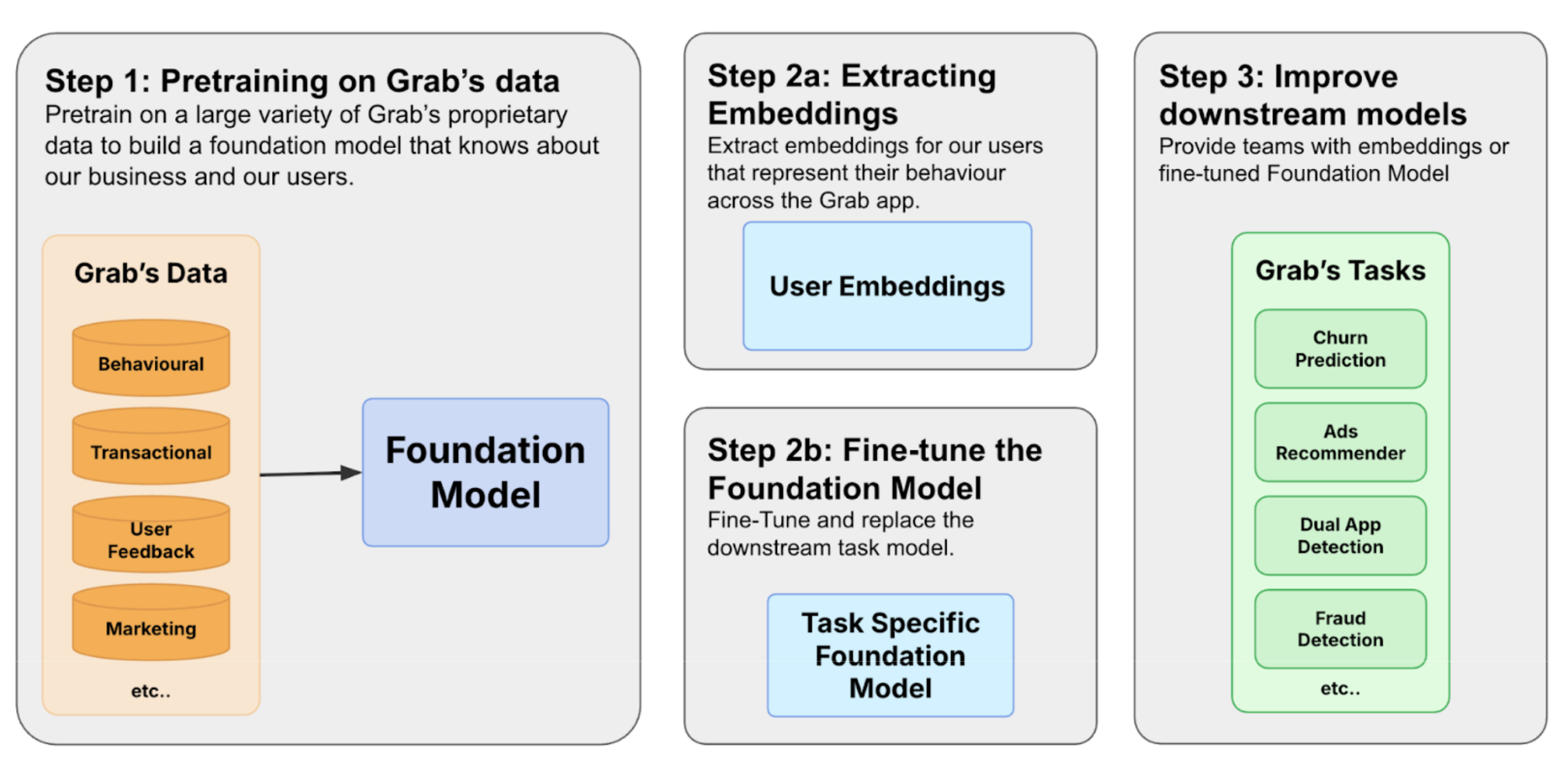
Figure 1. The process of building a foundation model involves three steps.

We build foundation models by first constructing a diverse training corpus encompassing user, merchant, and driver interactions. The pre-trained model can then be used in two ways. Based on Figure 1, in 2a we extract user embeddings from the model to serve downstream tasks to improve user understanding. The other path is 2b, where we fine-tune the model to make predictions directly.

Crafting a foundation model for Grab’s users

Grab’s journey towards building its own foundation model began with a clear recognition: existing models are not well-suited to our data. A general-purpose Large Language Model (LLM), for example, lacks the contextual understanding required to interpret why a specific geohash represents a bustling mall rather than a quiet residential area. Yet, this level of insight is precisely what we need for effective personalisation. This challenge extends beyond IDs, encompassing our entire ecosystem of text, numerical values, locations, and transactions.

Moreover, this rich data exists in two distinct forms: tabular data that captures a user’s long-term profile, and sequential time-series data that reflects their immediate intent. To truly understand our users, we needed a model capable of mastering both forms simultaneously. It became evident that off-the-shelf solutions would not suffice, prompting us to develop a custom foundation model tailored specifically to our users and their unique data.

The importance of data
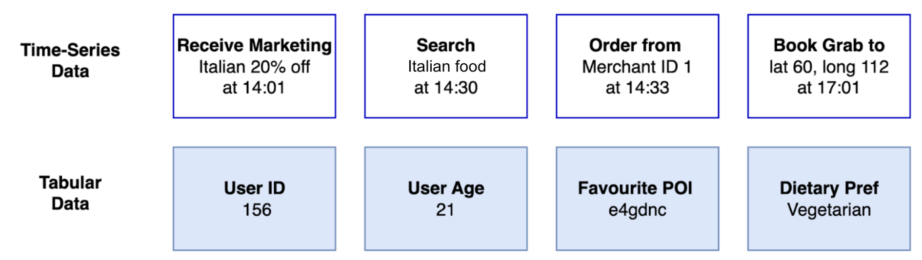
Figure 2. We use tabular and time-series data to build user embeddings.

The success of foundation models hinges on the quality and diversity of the datasets used for training. Grab identified two essential sources of data for building user embeddings as shown in Figure 2. Tabular data provides general attributes and long-term behavior. Time-series data reflects how the user uses the app and captures the evolution of user preferences.

  • Tabular data: This classic data source provides general user attributes and insights into long-term behavior. For example, this includes attributes like a user’s age and saved locations, along with aggregated behavioral data such as their average monthly spending or most frequently used service.

  • Time-series clickstream data: Sequential data captures the dynamic nature of user decision-making and trends. Grab tracks every interaction on its app, including what users view, click, consider, and ultimately transact. Additionally, metrics like the duration between events reveal insights into user decisiveness. Time-series data provides a valuable perspective on evolving user preferences.

A successful user foundation model must be capable of integrating both tabular and time-series data. Adding to the complexity is the diversity of data modalities, including categorical/text, numerical, user IDs, images, and location data. Each modality carries unique information, often specific to Grab’s business, underscoring the need for a bespoke architecture.

This inherent diversity in data modalities distinguishes Grab from many other platforms. For example, a video recommendation platform primarily deals with a single modality: videos, supplemented by user interaction data such as watch history and ratings. Similarly, social media platforms are largely centred around posts, images, and videos. In contrast, Grab’s identity as a “superapp” generates a far broader spectrum of user actions and data types. As users navigate between ordering food, booking taxis, utilising courier services, and more, their interactions produce a rich and varied data trail that a successful model must be able to comprehend. Moreover, an effective foundation model for Grab must not only create embeddings for our users but also for our merchant-partners and driver-partners, each of whom brings their own distinctive sets of data modalities.

Examples of data modalities at Grab

To illustrate the breadth of data, consider these examples across different modalities:

  • Text: This includes user-provided information such as search queries within GrabFood or GrabMart (“chicken rice,” “fresh milk”) and reviews or ratings for drivers and restaurants. For merchants, this could encompass the restaurant’s name, menu descriptions, and promotional texts.

  • Numerical: This modality is rich with data points such as the price of a food order, the fare for a ride, the distance of a delivery, the waiting time for a driver, and the commission earned by a driver-partner. User behavior can also be quantified through numerical data, such as the frequency of app usage or average spending over a month.

  • Merchant/User/Driver ID: These categorical identifiers are central to the platform. A user_id tracks an individual’s activity across all of Grab’s services. A merchant_id represents a specific restaurant or store, linking to its menu, location, and order history. A driver_id corresponds to a driver-partner, associated with their vehicle type, service area, and performance metrics.

  • Location data: Geographic information is fundamental to Grab’s operations. This includes airport locations, malls, pickup and drop-off points for a ride ((lat_A, lon_A) to (lat_B, lon_B)), the delivery address for a food order, and the real-time location of drivers. This data helps in understanding user routines (e.g., commuting patterns) and logistical flows.

The challenges and opportunities of diverse modalities

The sheer variety of these data modalities presents several significant challenges and opportunities for building a unified user foundation model:

  • Data heterogeneity: The different data types—text, numbers, geographical coordinates, and categorical IDs do not naturally lend themselves to being combined. Each modality has its own unique structure and requires specialised processing techniques before it can be integrated into a single model.

  • Complex interactions as an opportunity: The relationships between different modalities are often intricate, revealing a user’s context and intent. A model that only sees one data type at a time will miss the full picture.

For example, consider a single user’s evening out. The journey begins when they book a ride (involving their user_id and a driver_id) to a specific drop-off point, such as a popular shopping mall (location data). Two hours later, from that same mall location, they open the app again and perform a search for “Japanese food” (text data). They then browse several restaurant profiles (merchant_ids) before placing an order, which includes a price (numerical data).

A traditional, siloed model would treat the ride and the food search as two independent events. However, the real opportunity lies in capturing the interactions within a single user’s journey. This is precisely what our unified foundation model is designed to achieve: to identify the connections and recognise that the drop-off location of a ride provides valuable context for a subsequent text search. A model that understands a location is not merely a coordinate, but a place that influences a user’s next action, can develop a far deeper understanding of user context. Unlocking this capability is the key to achieving superior performance in downstream tasks, such as personalisation.

Model architecture
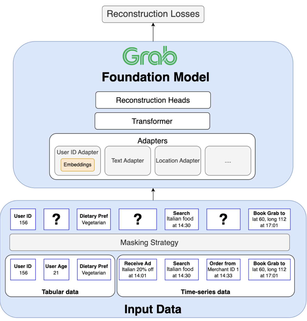
Figure 3. Transformer architecture

Figure 3 displays Grab’s transformer architecture, enabling joint pre-training on tabular and time-series data with different modalities. Grab’s foundation model is built on a transformer architecture specifically designed to tackle four fundamental challenges inherent to Grab’s superapp ecosystem:

  1. Jointly training on tabular and time-series data: A core requirement is to unify column order invariant tabular data (e.g. user attributes) with order-dependent time-series data (e.g. a sequence of user actions) within a single, coherent model.

  2. Handling a wide variety of data modalities: The model must process and integrate diverse data types, including text, numerical values, categorical IDs, and geographic locations, each requiring its own specialised encoding techniques.

  3. Generalising beyond a single task: The model must learn a universal representation from the entire ecosystem to power a wide array of downstream applications (e.g., recommendations, churn prediction, logistics) across all of Grab’s verticals.

  4. Scaling to massive entity vocabularies: The architecture must efficiently handle predictions across vocabularies containing hundreds of millions of unique entities (users, merchants, drivers), a scale that makes standard classification techniques computationally prohibitive.

In the following section, we highlight how we tackled each challenge.

1. Unifying tabular and time-series data
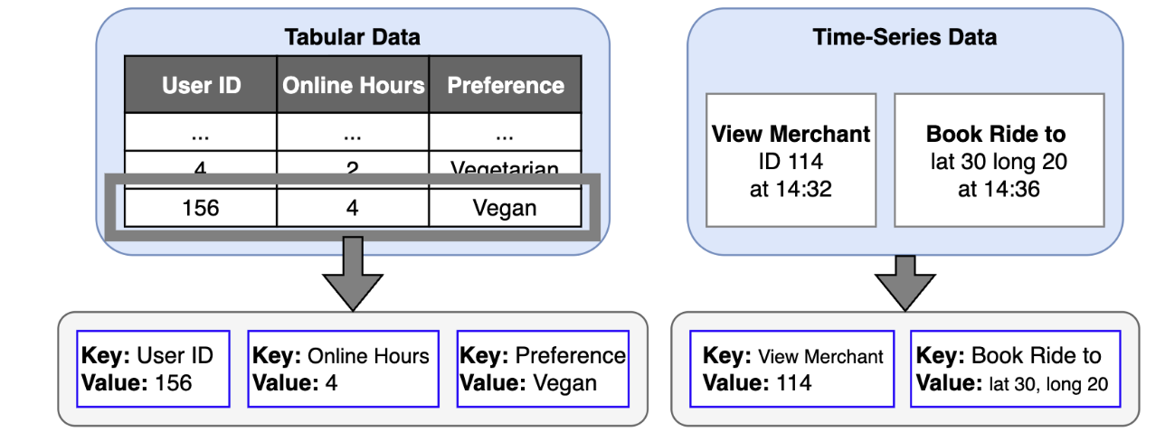
Figure 4. Differences between tabular data and time-series data

A key architectural challenge lies in jointly training on both tabular and time-series data. Tabular data, which contains user attributes, is inherently order-agnostic — the sequence of columns does not matter. In contrast, time-series data is order-dependent, as the sequence of user actions is critical for understanding intent and behavior.

Traditional approaches often process these data types separately or attempt to force tabular data into a sequential format. However, this can result in suboptimal representations, as the model may incorrectly infer meaning from the arbitrary order of columns.

Our solution begins with a novel tokenisation strategy. We define a universal token structure as a key:value pair.

  • For tabular data, the key is the column name (e.g. online_hours) and the value is the user’s attribute (e.g. 4).

  • For time-series data, the key is the event type (e.g. view_merchant) and the value is the specific entity involved (e.g. merchant_id_114).

This key:value format creates a common language for all input data. To preserve the distinct nature of each data source, we employ custom positional embeddings and attention masks. These components instruct the model to treat key:value pairs from tabular data as an unordered set while treating tokens from time-series data as an ordered sequence. This allows the model to benefit from both data structures simultaneously within a single, coherent framework.

2. Handling diverse modalities with an adapter-based design

The second major challenge is the sheer variety of data modalities: user IDs, text, numerical values, locations, and more. To manage this diversity, our model uses a flexible adapter-based design. Each adapter acts as a specialised “expert” encoder for a specific modality, transforming its unique data format into a unified, high-dimensional vector space.

  • For modalities like text, adapters can be initialised with powerful pre-trained language models to leverage their existing knowledge.

  • For ID data like user/merchant/driver IDs, we initialise dedicated embedding layers.

  • For complex and specialised data like location coordinates or not-so-well-modeled modalities like numbers in existing LLMs, we design custom adapters.

After each token passes through its corresponding modality adapter, an additional alignment layer ensures that all the resulting vectors are projected into the same representation space. This step is critical for allowing the model to compare and combine insights from different data types, for example, to understand the relationship between a text search query (“chicken rice”) and a location pin (a specific hawker center). Finally, we feed the aligned vectors into the main transformer model.

This modular adapter approach is highly scalable and future-proof, enabling us to easily incorporate new modalities like images or audio and upgrade individual components as more advanced architectures become available.

3. Unsupervised pre-training for a complex ecosystem

A powerful model architecture is only half the story; the learning strategy determines the quality and generality of the knowledge captured in the final embeddings.

In the industry, recommender models are often trained using a semi-supervised approach. A model is trained on a specific, supervised objective, such as predicting the next movie a user will watch or whether they will click on an ad. After this training, the internal embeddings, which now carry information fine-tuned for that one task, can be extracted and used for related applications. This method is highly effective for platforms with a relatively homogeneous primary task, like video recommendation or social media platforms.

However, this single-task approach is fundamentally misaligned with the needs of a superapp. At Grab, we need to power a vast and diverse set of downstream use cases, including food recommendations, ad targeting, transport optimisation, fraud detection, and churn prediction. Training a model solely on one of these objectives would create biased embeddings, limiting their utility for all other tasks. Furthermore, focusing on a single vertical like Food would mean ignoring the rich signals from a user’s activity in Transport, GrabMart, and Financial Services, preventing the model from forming a truly holistic understanding.

Our goal is to capture the complex and diverse interactions between our users, merchants, and drivers across all verticals. To achieve this, we concluded that unsupervised pre-training is the most effective path forward. This approach allows us to leverage the full breadth of data available, learning a universal representation of the entire Grab ecosystem without being constrained to a single predictive task.

To pre-train our model on tabular and time-series data, we combine masked language modeling (reconstructing randomly masked tokens) with next action prediction. On a superapp like Grab, a user’s journey is inherently unpredictable. A user might finish a ride and immediately search for a place to eat, or transition from browsing groceries on GrabMart to sending a package with GrabExpress. The next action could belong to any of our diverse services like mobility, deliveries, or financial services.

This ambiguity means the model faces a complex challenge: it’s not enough to predict which item a user might choose; it must first predict the type of interaction they will even initiate. Therefore, to capture the full complexity of user intent, our model performs a dual prediction that directly mirrors our key:value token structure:

  • It predicts the type of the next action, such as click_restaurant, book_ride, or search_mart.

  • It predicts the value associated with that action, like the specific restaurant ID, the destination coordinates, or the text of the search query.

This dual-prediction task forces the model to learn the intricate patterns of user behavior, creating a powerful foundation that can be extended across our entire platform. To handle these predictions, where the output could be of any modality (an ID, a location, text, etc.), we employ modality-specific reconstruction heads. Each head is designed for a particular data type and uses a tailored loss function (e.g. cross-entropy for categorical IDs, mean squared error for numerical values) to accurately evaluate the model’s predictions.

4. The ID reconstruction challenge

A significant challenge is the sheer scale of our categorical ID vocabularies. The total number of unique merchants, users, and drivers on the Grab platform runs into the hundreds of millions. A standard cross-entropy loss function would require a final prediction layer with a massive output dimension. For instance, a vocabulary of 100 million IDs with a 768-dimension embedding would result in a prediction head of nearly 80 billion parameters, blowing up model parameter count.

To overcome this, we employ hierarchical classification. Instead of predicting from a single flat list of millions of IDs, we first classify IDs into smaller, meaningful groups based on their attributes (e.g. by city, cuisine type, etc). This is followed by a second-stage prediction within that much smaller subgroup. This technique dramatically reduces the computational complexity, making it feasible to learn meaningful representations for an enormous vocabulary of entities.

Extracting value from our foundation model
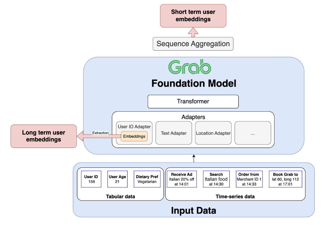
Figure 5. Our foundation model is pre-trained with tabular and time-series data.

Once our foundation model is pre-trained on the vast and diverse data within the Grab ecosystem, it becomes a powerful engine for driving business value. There are two primary pathways to harness its capabilities: fine-tuning and embedding extraction.

The first pathway involves fine-tuning the entire model on a labeled dataset for a specific downstream task, such as churn probability or fraud detection, to create a highly specialised and performant predictor.

The second, more flexible pathway is to use the model to generate powerful pre-trained embeddings. These embeddings serve as rich, general-purpose features that can support a wide range of separate downstream models. The remainder of this section will focus on this second pathway, exploring the types of embeddings we extract and how they empower our applications.

The dual-embedding strategy: Long-term and short-term memory

Our architecture is deliberately designed to produce two distinct but complementary types of user embeddings, providing a holistic view by capturing both the user’s stable, long-term identity and their dynamic, short-term intent.

The long-term representation: A stable identity profile

The long-term embedding captures a user’s persistent habits, established preferences, and overall persona. This representation is the learned vector for a given user_id, which is stored within the specialised User ID adapter. As the model trains on countless sequences from a user’s history, the adapter learns to distill their consistent behaviors into this single, stable vector. After training, we can directly extract this embedding, which effectively serves as the user’s “long-term memory” on the platform.

The short-term representation: A snapshot of recent intent

The short-term embedding is designed to capture a user’s immediate context and current mission. To generate this, a sequence of the user’s most recent interactions is processed through the model’s adapters and main transformer block. A Sequence Aggregation Module then condenses the transformer’s output into a single vector. This creates a snapshot of recent user intent, reflecting their most up-to-date activities and providing a fresh understanding of what they are trying to accomplish.

Scaling the foundation: From terabytes of data to millions of daily embeddings
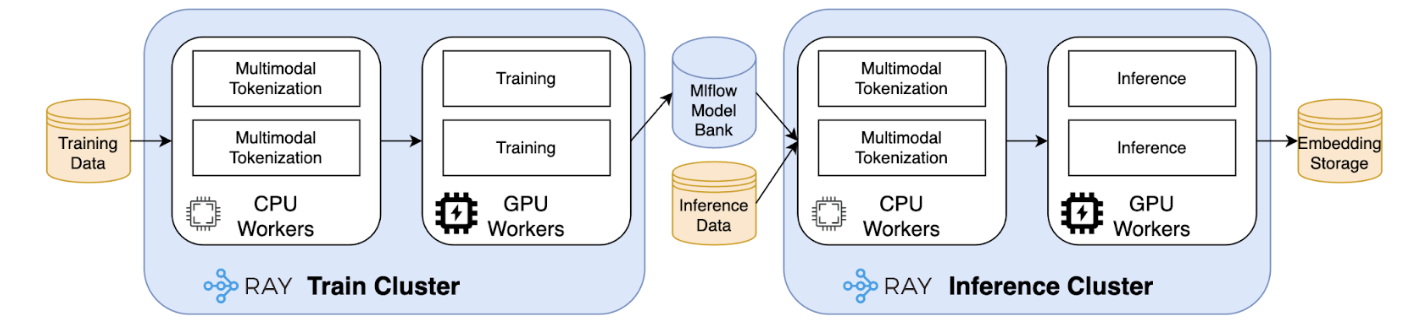
Figure 6. Ray framework

Building a foundation model of this magnitude introduces monumental engineering challenges that extend beyond the model architecture itself. The practical success of our system hinges on our ability to solve two distinct scalability problems:

  • Massive-scale training: Pre-training our model involves processing terabytes of diverse, multimodal data. This requires a distributed computing framework that is not only powerful but also flexible enough to handle our unique data processing needs efficiently.

  • High-throughput inference: To keep our user understanding current, we must regenerate embeddings for millions of active users daily. This demands a highly efficient, scalable, and reliable batch processing system.

To meet these challenges, we built upon the Ray framework, an open-source standard for scalable computing. This choice allows us to manage both training and inference within a unified ecosystem, tailored to our specific needs.

Core principle: A unified architecture for heterogeneous workloads

As illustrated by the Ray framework, both our training and inference pipelines share a fundamental workflow: they begin with a complex Central Processing Unit (CPU) intensive data preprocessing stage (tokenisation), which is followed by a Graphics Processing Unit (GPU) intensive neural network computation.

A naive approach would bundle these tasks together, forcing expensive GPU resources to sit idle while the CPU handles data preparation. Our core architectural principle is to decouple these workloads. Using Ray’s native ability to manage heterogeneous hardware, we create distinct, independently scalable pools of CPU and GPU workers.

This allows for a highly efficient, assembly-line-style process. Data is first ingested by the CPU workers for parallelised tokenisation. The resulting tensors are then streamed directly to the GPU workers for model computation. This separation is the key to achieving near-optimal GPU utilisation, which dramatically reduces costs and accelerates processing times for both training and inference.

Distributed training

Applying this core principle, our training pipeline efficiently processes terabytes of raw data. The CPU workers handle the complex key:value tokenisation at scale, ensuring the GPU workers are consistently fed with training batches. This robust setup significantly reduces the end-to-end training time, enabling faster experimentation and iteration. We will go into more detail on our training framework in a future blog post.

Efficient and scalable daily inference

This same efficient architecture is mirrored for our daily inference task. To generate fresh embeddings for millions of users, we leverage Ray Data—an open-source library used for data processing in AI and Machine Learning (ML) workload, to execute a distributed batch inference pipeline. The process seamlessly orchestrates our CPU workers for tokenisation and our GPU workers for model application.

This batch-oriented approach is the key to our efficiency, allowing us to process thousands of users’ data simultaneously and maximise throughput. This robust and scalable inference setup ensures that our dozens of downstream systems are always equipped with fresh, high-quality embeddings, enabling the timely and personalised experiences our users expect.

Conclusion: A general foundation for intelligence across Grab

The development of our user foundation model marks a pivotal shift in how Grab leverages AI. It moves us beyond incremental improvements on task-specific models toward a general, unified intelligence layer designed to understand our entire ecosystem. While previous efforts at Grab have combined different data modalities, this model is the first to do so at a foundational level, creating a truly holistic and reusable understanding of our users, merchants, and drivers.

The generality of this model is its core strength. By pre-training on diverse and distinct data sources from across our platform—ranging from deep, vertical-specific interactions to broader behavioral signals—it is designed to capture rich, interconnected signals that task-specific models invariably miss. The potential of this approach is immense: a user’s choice of transport can become a powerful signal to inform food recommendations, and a merchant’s location can help predict ride demand.

This foundational approach fundamentally accelerates AI development across the organisation. Instead of starting from scratch, teams can now build new models on top of our high-quality, pre-trained embeddings, significantly reducing development time and improving performance. Existing models can be enhanced by incorporating these rich features, leading to better predictions and more personalised user experiences. Key areas such as ad optimisation, dual app prediction, fraud detection, and churn probability already heavily benefit from our foundation model, but this is just the beginning.

Our vision for the future

Our work on this foundation model is just the beginning. The ultimate goal is to deliver “embeddings as a product”. A stable, reliable, and powerful basis for any AI-driven application at Grab. While our initial embeddings for users, driver-partners, and merchant-partners have already proven their value, our vision extends to becoming the central provider for all fundamental entities within our ecosystem, including Locations, Bookings, Marketplace items, and more.

To realise this vision, we are focused on a path of continuous improvement across several key areas:

  • Unifying and enriching our datasets: Our current success comes from leveraging distinct, powerful data sources that capture different facets of the user journey. The next frontier is to unify these streams into a single, cohesive training corpus that holistically represents user activity across all of Grab’s services. This effort will create a comprehensive, low-noise view of user behavior, unlocking an even deeper level of insight.

  • Evolving the model architecture: We will continue to evolve the model itself, focusing on research to enhance its learning capabilities and predictive power to make the most of our increasingly rich data.

  • Improving scale and efficiency: As Grab grows, so must our systems. We are dedicated to further scaling our training and inference infrastructure to handle more data and complexity at an even greater efficiency.

By providing a continuously improving, general-purpose understanding of these core components, we are not just building a better model; we are building a more intelligent future for Grab. This enables us to innovate faster and deliver exceptional value to the millions who rely on our platform every day.

Join us

Grab is a leading superapp in Southeast Asia, operating across the deliveries, mobility and digital financial services sectors. Serving over 800 cities in eight Southeast Asian countries, Grab enables millions of people everyday to order food or groceries, send packages, hail a ride or taxi, pay for online purchases or access services such as lending and insurance, all through a single app. Grab was founded in 2012 with the mission to drive Southeast Asia forward by creating economic empowerment for everyone. Grab strives to serve a triple bottom line – we aim to simultaneously deliver financial performance for our shareholders and have a positive social impact, which includes economic empowerment for millions of people in the region, while mitigating our environmental footprint.

Powered by technology and driven by heart, our mission is to drive Southeast Asia forward by creating economic empowerment for everyone. If this mission speaks to you, join our team today!
Powering Partner Gateway metrics with Apache Pinot

Post Syndicated from Grab Tech original https://engineering.grab.com/pinot-partnergateway-tech-blog

Introduction

Grab operates as a dynamic ecosystem involving partners and various service providers, necessitating real-time intelligence and decision-making for seamless integration and service delivery. To facilitate this, GrabDeveloper serves as Grab’s centralized platform for developers and partners. It supports API integration, partner onboarding, and product management. It also provides tech support through staging and production portals with detailed documentation.

Working alongside Developer Home, Partner Gateway acts as Grab’s secure interface for exposing APIs to third-party entities. It enables seamless interactions between Grab’s hosted services and external consumers, such as mobile apps, web browsers, and partners. Partner Gateway enhances the experience by offering advanced metrics tracking through time-series charts and dashboards. Partner Gateway delivers actionable insights that ensure high performance, reliability, and user satisfaction in application integrations with Grab services.

Use cases

Let’s explore GrabDeveloper integration use cases with one of our partners, whom we’ll refer to as “Alpha.” Alpha is a company that specializes in producing and distributing a diverse range of perishable goods. To optimize their operations, time-series charts tracking API traffic request status codes and average API response times play a crucial role.

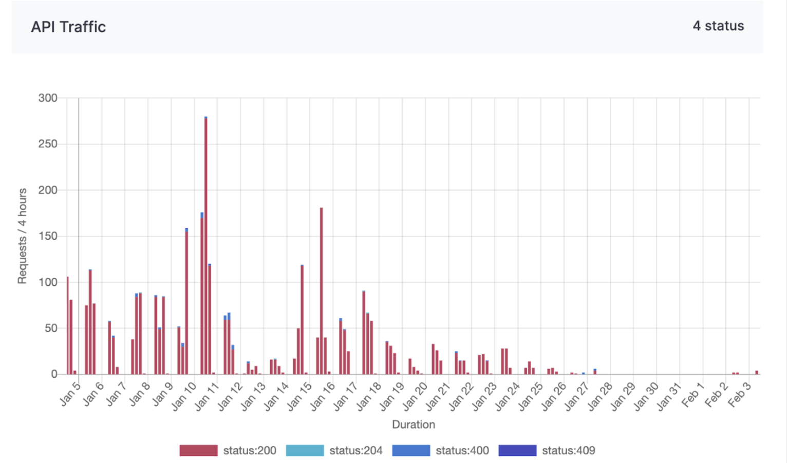
API traffic request service status codes chart

Time-series charts tracking API traffic request status codes offer valuable insights into the performance and reliability of APIs used for managing supply chain logistics, customer orders, and distribution networks. By monitoring these status codes, Alpha can promptly detect and resolve disruptions or failures in their digital systems, ensuring seamless operations and minimizing downtime.

Figure 1: API traffic chart from 5th Jan 2025 to 4th Mar 2025.

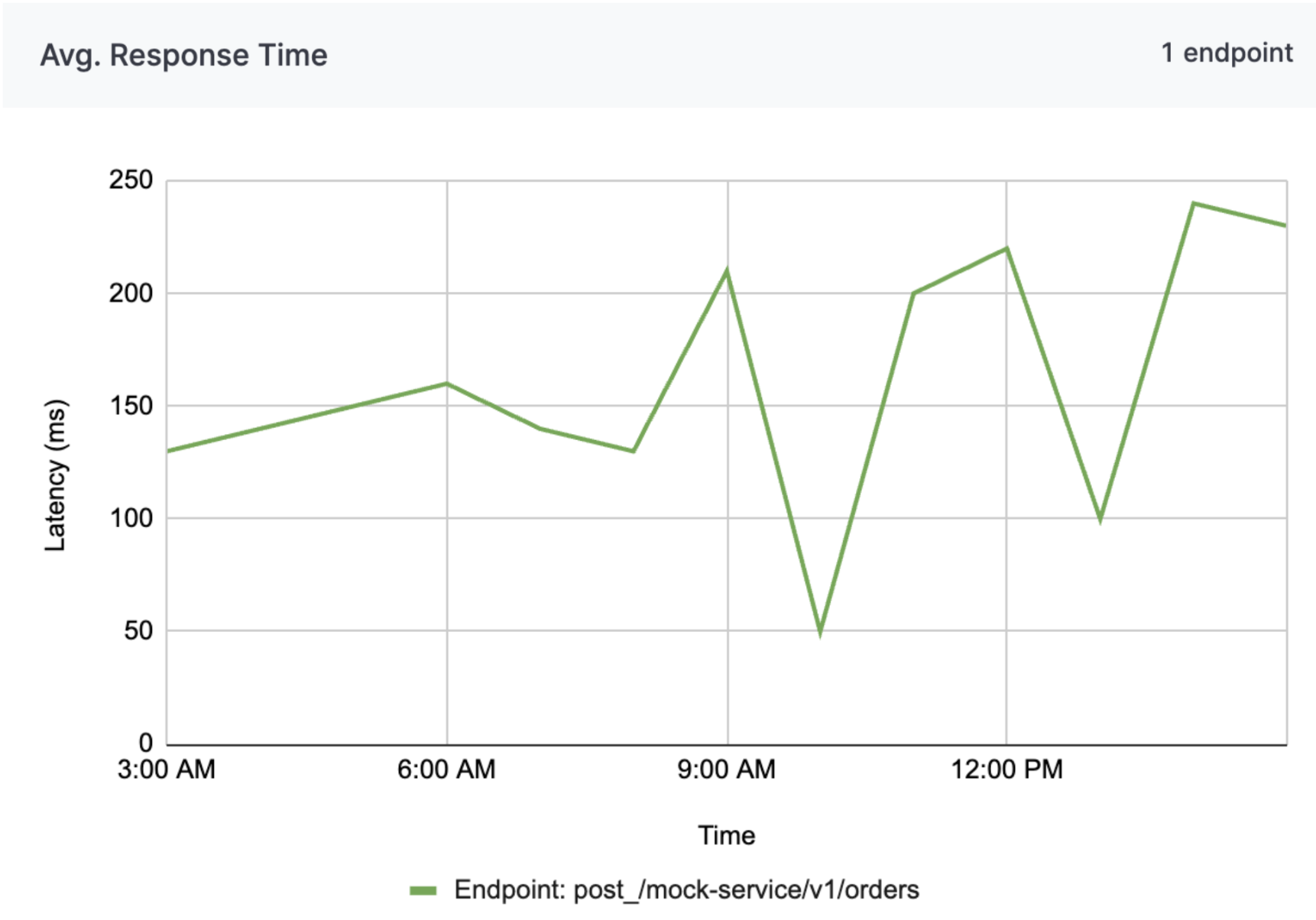
API average response times chart

Analyzing average response times helps the company maintain efficient communication between various systems, enhancing the speed and reliability of transactions and data exchanges. This proactive monitoring supports Alpha in delivering consistent, high-quality service to customers and partners, ultimately contributing to improved operational efficiency and customer satisfaction.

Analyzing average response times enables a company to ensure efficient communication across various systems, enhancing transaction speed and data exchange reliability. Proactive monitoring helps Alpha deliver consistent, high-quality service to customers and partners, boosting operational efficiency and customer satisfaction.

Figure 2: Average response time chart from 12 Mar 2025 3am to 12 Mar 2025 3pm (Endpoints are mocked for security purposes).

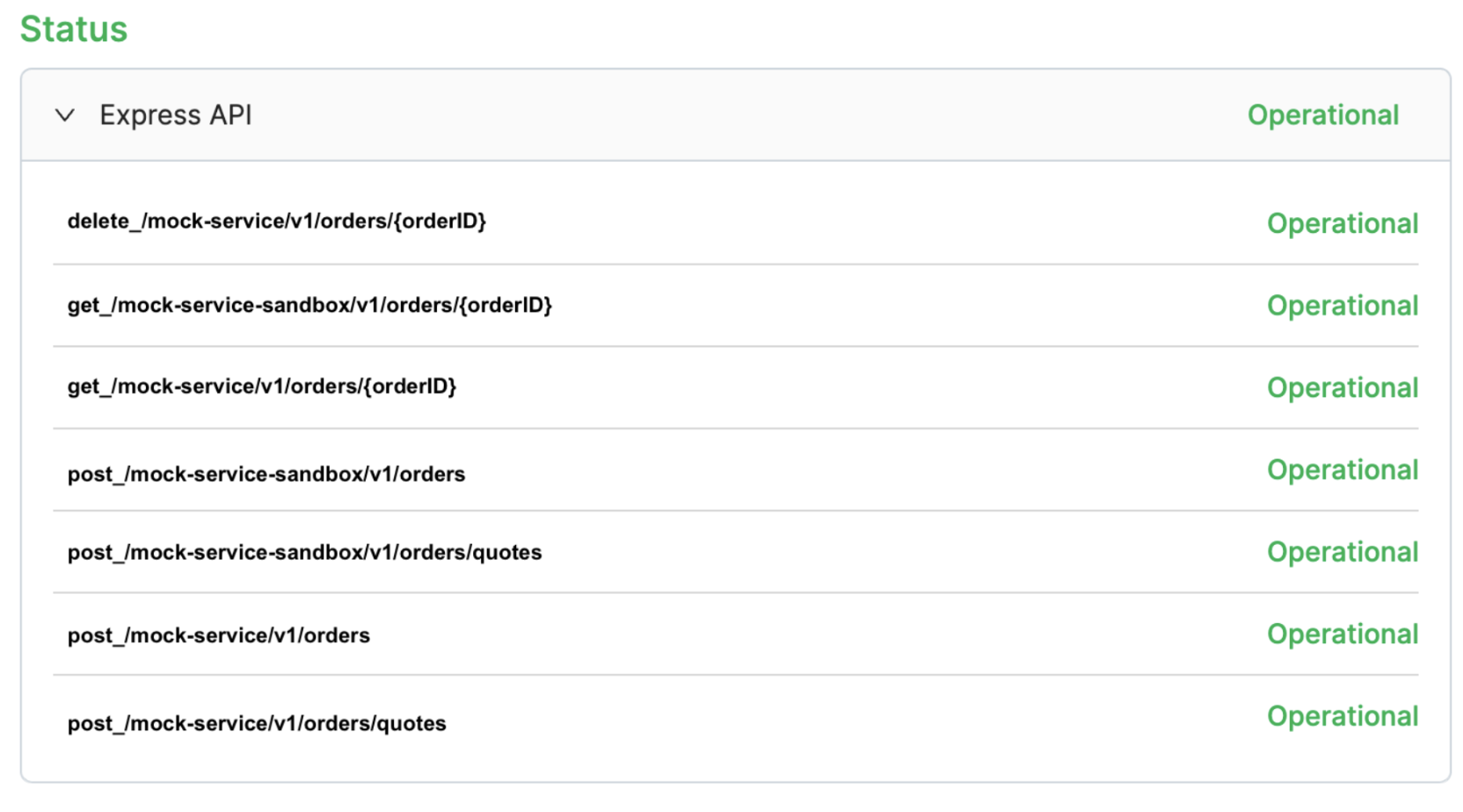
Endpoint status dashboard

For Alpha, the endpoint status dashboard delivers real-time insights into API performance, enabling swift issue resolution and seamless integration with the company’s systems. The dashboard enhances service reliability, supports business operations, and ensures uninterrupted data exchange, all of which are critical for Alpha’s business processes and customer satisfaction. Furthermore, the transparency and reliability provided by the dashboard strengthens trust in the partnership, ensuring Alpha to confidently rely on the integration to drive their digital initiatives and operational goals.

Figure 3: Endpoint status dashboard of express API for company Alpha. *Endpoints are mocked for security purposes.

Why choose Apache Pinot and what is it?

To accommodate these use cases, we need a backend storage system engineered for low-latency queries across a wide range of temporal intervals, spanning from one-hour snapshots to 30-day retrospective analyses, whereby it could contain up to ~6.8 billion rows of data in a 30 day period for a particular dataset. This led us to choose Apache Pinot for these use cases, a distributed Online Analytical Processing (OLAP) system designed for low-latency analytical queries on large-scale data with millisecond query latencies.

Apache Pinot is a real-time distributed OLAP datastore designed to deliver low-latency analytics on large-scale data. It is optimized for high-throughput ingestion and real-time query processing making it ideal for scenarios such as user-facing analytics, dashboards, and anomaly detection. Apache Pinot supports complex queries, including aggregations and filtering. It delivers sub-second response times by leveraging techniques like columnar storage, indexing, and data partitioning to achieve efficient query execution.

Data ingestion process

Figure 4: Data ingestion process.
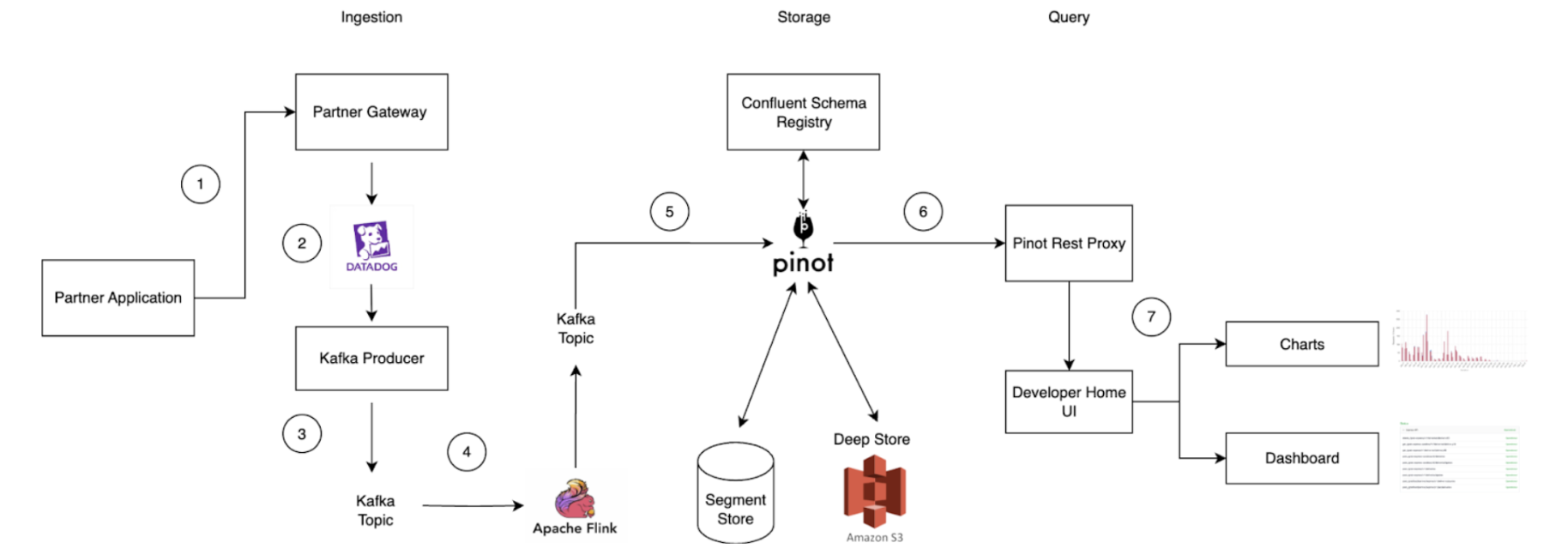
  1. API call initiation: An API call is made on the partner application and routed through the Partner Gateway.
  2. Metric tracking: Dimensions such as client ID, partner ID, status code, endpoint, metric name, timestamp, and value (which is the metric) are tracked and uploaded to Datadog, a cloud-based monitoring platform.
  3. Kafka message transformation: Within the partner gateway code, an Apache Kafka Producer converts these metrics into Kafka messages and stores them in a Kafka Topic. Grab utilizes Protobuf for serialization and deserialization of Kafka messages. Since Grab’s Golang Kafka ecosystem does not use the Confluent Schema Registry, Kafka messages must be serialized with a magic byte which indicates that they are using Confluent’s Schema Registry, followed by the Schema ID.
  4. Serialization via Apache Flink: Serialization is managed using Apache Flink, an open-source stream processing framework. This ensures compatibility with the Confluent Schema Registry Protobuf Decoder plugin on Apache Pinot. The messages are then written to a separate Kafka Topic.
  5. Ingestion to Apache Pinot: Messages from the Kafka Topic containing the magic byte are ingested directly into Pinot, which references the Confluent Schema Registry to accurately deserialize the messages.
  6. Query execution: Queries on the Pinot table can be executed via the Pinot Rest Proxy API.
  7. Data visualization: Users can view their project charts and dashboards on the GrabDeveloper Home UI, where data points are retrieved from queries executed in step 6.

Challenges faced

During the initial setup, we encountered significant performance challenges when executing aggregation queries on large datasets exceeding 150GB. Specifically, attempts to retrieve and process data for periods ranging from 20 to 30 days resulted in frequent timeout issues as the queries took longer than 10 seconds. This was particularly concerning as it compromised our ability to meet our Service Level Agreement (SLA) of delivering query results within 300 milliseconds. The existing query infrastructure struggled to efficiently manage the volume and complexity of data within the required timeframe, necessitating optimization efforts to improve performance and reliability.

Solution

Drawing from the insights gained on the limitations of our initial solutions, we implemented these strategic optimizations to significantly enhance our table’s performance.

Partitioning by metric name

  • Improved data locality: Partitioning the Kafka Topic by metric name ensures that related data is grouped together. When a query filters on a specific metric, Pinot can directly access the relevant partitions, minimizing the need to scan unrelated data. This significantly reduces I/O overhead and processing time.
  • Efficient query pruning: By physically partitioning data, only the servers holding the relevant partitions are queried. This leads to more efficient query pruning, as irrelevant data is excluded early in the process, further optimizing performance.
  • Enhanced parallel processing: Partitioning enables Pinot to distribute queries across multiple nodes, allowing different metrics to be processed in parallel. This leverages distributed computing resources, accelerating query execution and improving scalability for large datasets.

Column based on aggregation intervals

Table 1
  • Facilitates time-based aggregations: Rounded time columns (e.g., Timestamp_1h for hourly intervals) group data into coarser time buckets, enabling efficient aggregations such as hourly or daily metrics. This simplifies indexing and optimizes storage by precomputing aggregates for specific time intervals.
  • Efficient data filtering: Rounded time columns allow for precise filtering of data within specific aggregation intervals. For example, the query SELECT SUM(Value) FROM Table WHERE Timestamp_1h = '2025-01-20 01:00:00' can exclude irrelevant columns (e.g., column 2) and focus only on rows within the specified time interval, further enhancing query efficiency.

Utilizing the Star-tree index in Apache Pinot

The Star-tree Index in Apache Pinot is an advanced indexing structure that enhances query performance by pre-aggregating data across multiple dimensions (e.g., D1, D2). It features a hierarchical tree with a root node, leaf nodes (holding up to T records), and non-leaf nodes that split into child nodes when exceeding T records. Special star nodes store pre-aggregated records by omitting the splitting dimension. The tree is constructed based on a dimensionSplitOrder, dictating node splitting at each level.

Sample table configuration for Star-tree index:

"tableIndexConfig": {
  "starTreeIndexConfigs": [{
    "dimensionsSplitOrder": [
      "Metric",
      "Endpoint",
      "Timestamp_1h"
    ],
    "skipStarNodeCreationForDimensions": [
    ],
    "functionColumnPairs": [
      "AVG__Value"
    ],
    "maxLeafRecords": 1
  }],
  ...
}

Configuration explanation:

  • dimensionsSplitOrder: This specifies the order in which dimensions are split at each level of the tree. The order is “Metric”, “Endpoint”, “Timestamp_1h”. This means the tree will first split by Metric, then by Endpoint, and finally by Timestamp_1h.
  • skipStarNodeCreationForDimensions: This array is empty, indicating that star nodes will be created for all dimensions specified in the split order. No dimensions are omitted from star node creation.
  • functionColumnPairs: This specifies the aggregation functions to be applied to columns when creating star nodes. The configuration includes “AVG__Value”, meaning the average of the “Value” column will be calculated and stored in star nodes.
  • maxLeafRecords: This is set to 1, indicating that each leaf node will contain only one record. If a node exceeds this number, it will split into child nodes.

Star-tree diagram

Figure 5: Star-tree Index Structure.

Components:

  • Root node (orange): This is the starting point for traversing the tree structure.
  • Leaf node (blue): These nodes contain up to a configurable number of records, denoted by T. In this configuration, maxLeafRecords is set to 1, meaning each leaf node will contain a maximum of one record.
  • Non-leaf node (green): These nodes will split into child nodes if they exceed the maxLeafRecords threshold. Since maxLeafRecords is set to 1, any node with more than one record will split.
  • Star-node (yellow): These nodes store pre-aggregated records by omitting the dimension used for splitting at that level. This helps in reducing the data size and improving query performance.

Example:

A practical explanation of the start-tree diagram would be to display the star-tree documents in a table format along with the sample queries used to retrieve the data.

Table 2: Star-tree documents table

Sample queries:

Select SUM(Value) FROM Table:
With no group-by clause, select the Star-Node for all dimensions (document 19) to quickly obtain the aggregated result of 250 by processing just this document.

Select SUM(Value) FROM Table WHERE Metric = 'XYZ_Req_Count':
Select the node with XYZ_Req_Count for Metric, and the Star-Node for Endpoint and Timestamp_1h (document 12). This reduces processing to one document, returning an aggregated result of 130, instead of filtering and aggregating three documents (documents 7,8 9)

SELECT SUM(Value) FROM Table WHERE Timestamp_1h = '2025-01-20 00:00:00':
Select the Star-Node for Metric and Endpoint, and the node with '2025-01-20 00:00:00' for Timestamp_1h (document 16). This allows aggregation from a single document, yielding a result of 40.

SELECT SUM(Value) FROM Table GROUP BY Endpoint:
With a group-by on Endpoint, select the Star-Node for Metric and Timestamp_1h, and all non Star-Node for Endpoint (documents 13, 14, 15). Process one document per group to obtain the group-by results efficiently.

Comparing performance after the optimization

Figure 6: Chart of query latency with and without optimization.

The graph above in Figure 6, provides a comparison analysis of query performance, showcasing the significant improvements achieved through the implemented optimization solutions. The query execution times are significantly reduced, as evidenced by the logarithmic scale values.

For the first query which calculates the latency for a particular aggregation interval, the log scale indicates a reduction from 4.64 to 2.32, translating to a decrease in query latency from 43,713 to 209 milliseconds.

Similarly, the second query, which aggregates the sum of the latency based on the tags for a particular metric, shows a log scale reduction from 3.71 to 1.54, with query latency improving from 5,072 to 35 milliseconds. These results underscore the efficacy of optimization in enhancing query performance, enabling faster data retrieval and processing

Tradeoffs

Star-tree indexes in Apache Pinot are designed to significantly enhance query performance by pre-computing aggregations. This approach allows for rapid query execution by utilizing pre-calculated results, rather than computing aggregations on-the-fly. However, this performance boost comes with a tradeoff in terms of storage space.

Before implementing the Star-tree index, the total storage size for 30 days of data was approximately 192GB. With the Star-tree index, this increased to 373GB, nearly doubling the storage requirements. Despite the increase in storage, the performance benefits substantially outweigh the costs associated with additional storage.

The cost impact is relatively minor. We utilize AWS gp3 EBS volumes, which roughly cost $14.48 USD monthly for the extra table (calculated as 0.08 USD x 181 GB). This cost is considered insignificant when compared to the substantial gains in query performance. Alternatively, precomputing the metrics via an ETL job is also feasible; however, it is less cost-effective due to the additional expenses required to maintain the pipeline.

The decision to use Star-tree indexes is justified by the dramatic improvement in query speed, which enhances user experience and efficiency. The modest increase in storage costs is a worthwhile investment for achieving optimal performance.

Conclusion

In conclusion, Grab’s integration of Apache Pinot as a backend solution within the Partner Gateway represents a forward-thinking strategy to meet the evolving demands of real-time analytics. Apache Pinot’s ability to deliver low-latency queries empowers our partners with immediate, actionable insights into API performance that enhances their integration experience and operational efficiency. This is crucial for partners who require rapid data access to make informed decisions and optimize their services.

The adoption of Star-tree indexing within Pinot further refines our analytics infrastructure by strategically balancing the trade-offs between query latency and storage costs. This optimization ensures Partner Gateway can support a diverse range of use cases with subsecond query latencies while maintaining high performance and reliability in service delivery reinforcing Grab’s commitment to delivering superior performance across its ecosystem.

Ultimately, the integration of Apache Pinot enhances Grab’s real-time analytics capabilities while empowering the company to drive innovation and consistently deliver exceptional service to both partners and users.

Credits to Manh Nguyen from the Coban Infrastructure Team, Michael Wengle from the Midas Team and Yuqi Wang from the DevHome team.

Join us

Grab is a leading superapp in Southeast Asia, operating across the deliveries, mobility and digital financial services sectors. Serving over 800 cities in eight Southeast Asian countries, Grab enables millions of people everyday to order food or groceries, send packages, hail a ride or taxi, pay for online purchases or access services such as lending and insurance, all through a single app. Grab was founded in 2012 with the mission to drive Southeast Asia forward by creating economic empowerment for everyone. Grab strives to serve a triple bottom line – we aim to simultaneously deliver financial performance for our shareholders and have a positive social impact, which includes economic empowerment for millions of people in the region, while mitigating our environmental footprint.

Powered by technology and driven by heart, our mission is to drive Southeast Asia forward by creating economic empowerment for everyone. If this mission speaks to you, join our team today!
Taming the monorepo beast: Our journey to a leaner, faster GitLab repo

Post Syndicated from Grab Tech original https://engineering.grab.com/taming-monorepo-beast

At Grab, our engineering teams rely on a massive Go monorepo that serves as the backbone for a large portion of our backend services. This repository has been our development foundation for over a decade, but age brought complexity, and size brought sluggishness. What was once a source of unified code became a bottleneck that was slowing down our developers and straining our infrastructure.

A primer on GitLab, Gitaly, and replication

To understand our core problem, it’s helpful to know how GitLab handles repositories at scale. GitLab uses Gitaly, its Git RPC service, to manage all Git operations. In a high-availability setup like ours, we use a Gitaly Cluster with multiple nodes.

Here’s how it works:

  • Write operations: A primary Gitaly node handles all write operations.
  • Replication: Data is replicated to secondary nodes.
  • Read operations: Secondary nodes handle read operations, such as clones and fetches, effectively distributing the load across the cluster.
  • Failover: If the primary node fails, a secondary node can take over.
    For the system to function effectively, replication must be nearly instantaneous. When secondary nodes experience significant delays syncing with the primary—a condition called replication lag—GitLab stops routing read requests to the secondary nodes to ensure data consistency. This forces all traffic back to the primary node, eliminating the benefits of our distributed setup. Figure 1 illustrates the replication architecture of Gitaly nodes.
Figure 1: The replication architecture of Gitaly nodes in a high-availability setup.

The scale of our problem

Our Go monorepo started as a simple repository 11 years ago but ballooned as Grab grew. A Git analysis using the git-sizer utility in early 2025 revealed the shocking scale:

  • 12.7 million commits accumulated over a decade.
  • 22.1 million Git trees consuming 73GB of metadata.
  • 5.16 million blob objects totaling 176GB.
  • 12 million references, mostly leftovers from automated processes.
  • 429,000 commits deep on some branches.
  • 444,000 files in the latest checkout.

This massive size wasn’t just a number—it was crippling our daily operations.

Infrastructure problems

Figure 2: Replication delays of up to four minutes during peak working hours.

In high-availability setups, replication is critical for distributing workloads and ensuring system reliability. However, when replication delays occur, they can severely impact infrastructure performance and create bottlenecks. Figure 2 illustrates replication delays of up to four minutes which caused both secondary nodes, Gitaly S1 (orange) and Gitaly S2 (blue), to lag behind the primary node, Gitaly P (green). As a result, all requests were routed exclusively to the primary node, creating significant performance challenges.

The key issues here are:

  • Single point of failure: Only one of our three Gitaly nodes could handle the load, creating a bottleneck.
  • Throttled throughput: The system limits the read capacity to just one-third of the cluster’s potential.

Developer experience issues

The growing size of the monorepo directly impacted developer workflows:

  • Slow clones: 8+ minutes even on fast networks.
  • Painful Git operations: Every commit, diff, and blame had to process millions of objects.
  • CI pipeline overhead: Repository cloning added up 5-8 minutes to every CI job.
  • Frustrated developers: “Why is this repo so slow?” became a common question.

Operational challenges

The repository’s scale introduced significant operational hurdles:

  • Storage issues: 250GB of Git data made backups and maintenance cumbersome.
  • GitLab UI timeouts: The web interface struggled to handle millions of commits and refs, frequently timing out.
  • Limited CI scalability: Adding more CI runners overloaded the single working node.

All these factors were dragging down developer productivity. It was clear that continuing to let the monorepo grow unchecked wasn’t sustainable. We needed to make the repository leaner and faster, without losing the important history that teams relied on.

Our solution journey

Proof of concept: Validating the theory

Before making any changes, we needed to answer a critical question: “Would trimming repository history solve our replication issues?” Without proof, committing to such a major change felt risky. So we set out to test the idea.

The test setup:

We designed a simple experiment. In our staging environment, we created two repositories:

  • Full history repository: This repository mirrored the original repository with full history.
  • Shallow history repository: This repository contained only a single commit history.

Both repositories contained the same number of files and directories. We then simulated production-like load on both of the repositories.

The results:

  • Full history repository: 160-240 seconds replication delay.
  • Shallow history repository: 1-2.5 seconds replication delay.

This was nearly a 100x improvement in replication performance.

This proof of concept gave us confidence that history trimming was the right approach and provided baseline performance expectations.

Content preservation strategies: What to keep

Initial strategy: Time-based approach (1-2 years)

Initially, we wanted to keep commits from the last 1-2 years and archive everything else, as this seemed like a reasonable balance between recent history and size reduction. However, when we developed our custom migration script, we discovered it could only process 100 commits per hour, approximately 2,400 commits per day. With millions of commits in the original repository, even keeping 1-2 years of history would take months.

  • We can only process ~100 commits per hour in batches of 20 to avoid memory limits on GitLab runners.
  • Each batch takes 2 minutes to process, but requires 10 minutes of cleanup (git gc, git reflog expire) to prevent local disk and memory exhaustion.
  • This means each batch takes 12 minutes, allowing only 5 batches per hour (60 ÷ 12 = 5), totaling to 100 commits per hour (5 × 20 = 100).
  • Larger batches increased cleanup time and skipping cleanup caused jobs to crash after 200-300 commits.

The bottleneck wasn’t just the number of commits, it was the 10-minute cleanup process.

Additional constraints discovered:

As we dug deeper, we discovered more obstacles.

  • Critical dependencies extended beyond two years. Some Go module tags from six years ago were still actively used.
  • A pure time-based cut would break existing build pipelines.
  • Development teams needed some recent history for troubleshooting and daily operations.

Revised strategy: Tag-based + recent history

Given the processing speed constraint of 100 commits per hour, we needed to drastically reduce the number of commits while preserving essential functionality. After careful evaluation, we settled on a tag-based approach combined with recent history.

What we decided to keep:

  • Critical tags: All commits reachable by 2,000+ identified tags, ensuring semantic importance for releases and dependencies.
  • Recent history: Complete commit history for the last month only addressing stakeholder needs within processing constraints.
  • Simplified merge commits: Converted complex merge commits into single commits to further reduce processing time.

Why this approach worked:

  • Time-feasible: Reduced processing time from months to weeks.
  • Functionally complete: Preserved all tagged releases and recent development context.
  • Stakeholder satisfaction: Met development teams’ need for recent history.
  • Massive size reduction: Achieved 99.9% fewer commits while keeping what matters.

The trade-off:

We sacrificed deep historical browsing of 1 to 2 years for practical migration feasibility, while ensuring no critical functionality was lost.

Technical implementation methods: How to execute

Method 1: git filter-repo (Failed)

The approach: Use Git’s filter-repo tool with git replace --graft to remove commits older than a specified criteria.

Why it failed:

  • Complex history: Our repository’s highly non-linear history, with multiple branches and merges, made this approach impractical.
  • Workflow complexity: The process required numerous git replace --graft commands to account for various branches and dependencies, significantly complicating the workflow.
  • Risk of inconsistencies: The complexity introduced a high risk of errors and inconsistencies, making this method unsuitable.

Method 2: git rebase –onto (Failed)

The approach: Use git rebase --onto to preserve selected commits while pruning unwanted history.

Why it failed:

  • Scale issues: The repository size overwhelmed the rebase process.
  • Conflict resolution: High number of unexpected conflicts that couldn’t be resolved automatically.
  • Technical limitations: Batch processing couldn’t solve the performance issues; Git’s internal mechanisms struggled with the scale.

Method 3: Patch-based implementation (Failed)

The approach: Create and apply patches for each commit individually to preserve repository history.

Why it failed:

  • Merge commit complexity: Couldn’t maintain correct parent-child relationships for merge commits.
  • History integrity: Resulted in linear sequence instead of preserving original merge structure.
  • Missing commits: Important merge commits were lost or incorrectly applied.

Method 4: Custom migration script (Success!)

The breakthrough: A sophisticated custom script that could handle our specific requirements and processing constraints. Unlike traditional Git history rewriting tools, our script implements a two-phase chronological processing approach that efficiently handles large-scale repositories.

Phase 1: Bulk migration

In this phase, the script focuses on reconstructing history based on critical tags.

  1. Fetch tags chronologically: Retrieve all tags in the order they were created.
  2. Pre-fetch Large File Storage (LFS) objects: Collect LFS objects for tag-related commits before processing.
  3. Batch processing: Process tags in batches of 20 to optimize memory and network usage. For each tag:
    • Check for associated LFS objects.
    • Perform selective LFS fetch if required.
    • Create a new commit using the original tree hash and metadata.
    • Embed the original commit hash in the commit message for traceability.
    • Gracefully handle LFS checkout failures.

Then, push the processed batch of 20 commits to the destination repository, with LFS tolerance.

  1. Cleanup and continue: Perform cleanup operations after each batch and proceed to the next.

Phase 2: Delta migration

This phase integrates recent commits after the cutoff date.

  1. Fetch recent commits: Retrieve all commits created after the cutoff date in chronological order.
  2. Batch processing: Process commits in batches of 20 for efficiency. For each commit:
    • Check for associated LFS objects.
    • Perform selective LFS fetch if required.
    • Recreate the commit with its original metadata.
    • Embed the original commit hash for resumption tracking in case of interruptions.
    • Gracefully handle LFS checkout failures.

Then, push the processed batch of commits to the destination repository, with LFS tolerance.

  1. Tag mapping: Map tags to their corresponding new commit hashes.
  2. Push tags: Push related tags pointing to the correct new commits.
  3. Final validation: Validate all LFS objects to ensure completeness.

LFS handling

The script incorporates robust mechanisms to handle Git LFS efficiently.

  • Configure LFS for incomplete pushes.
  • Skip LFS download errors when possible.
  • Retry checkout with LFS smudge skip.
  • Perform selective LFS object fetching.
  • Gracefully degrade processing for missing LFS objects.

Key features:

  • Sequential processing of tags and commits in chronological order.
  • Resumable operations that could restart from the last processed item if interrupted.
  • Batch processing to manage memory and network resources efficiently.
  • Robust error handling for network issues and Git complications.
  • Maintains repository integrity while simplifying complex merge structures.
  • Optimized for our specific preservation strategy (tags + recent history).

Implementation: Executing the migration

With our strategy defined (tags + last month), we executed the migration using our custom script. This process involved careful planning, smart processing techniques, and overcoming technical challenges.

Smart processing approach

Our custom script employed several key strategies to ensure efficient and reliable migration:

  • Sequential tag processing: Replay tags chronologically to maintain logical history.
  • Resumable operations: The migration could restart from the last processed item if interrupted.
  • Batch processing: Handle items in manageable groups to prevent resource exhaustion.
  • Progress tracking: Monitor processing rate and estimated completion time.

Technical challenges solved

The migration addressed several critical technical hurdles.

  • Large file support: Handled Git LFS objects with incomplete push allowances.
  • Error handling: Robust retry logic for network issues and Git errors.
  • Merge commit simplification: Converted complex merge structures to linear commits.

Two-phase migration strategy

The migration was executed in two carefully planned phases.

  • Phase 1 – Bulk migration: Migrated 95% of tags while keeping the old repo live.
  • Phase 2 – Delta migration: Performed final synchronization during a maintenance window to migrate recent changes.

Results and impact

Infrastructure transformation

Replication delay, or the time required to sync across all Gitaly nodes, improved by 99.4% following the pruning process. As illustrated in Figures 3 and 4, the new pruned monorepo achieves replication in under ~1.5 seconds on average, compared to ~240 seconds for the old repository. This transformation eliminated the previous single-node bottleneck, enabling read requests to be distributed evenly across all three storage nodes, significantly enhancing system reliability and performance.

Figure 3: In the new pruned monorepo, replication delay ranges from 200 – 2,000 ms.
Figure 4: In the old monorepo, replication delay ranged from 16,000 – 28,000 ms.

The migration significantly improved load distribution across Gitaly nodes. As shown in Figure 5, the new monorepo leverages all three Gitaly nodes to serve requests, effectively tripling read capacity. Additionally, the migration eliminated the single point of failure that existed in the old monorepo, ensuring greater reliability and scalability.

Figure 5: In the new monorepo, requests are evenly distributed across all three servers, demonstrating improved performance and replication across nodes.
Figure 6: In the old monorepo, requests were served only by a single server during working hours, creating a single point of failure.

Performance improvements

The migration resulted in significant improvements across multiple areas.

  • Clone time: Reduced from 7.9 minutes to 5.1 minutes, achieving a 36% improvement, making repository cloning faster and more efficient.
  • Commit count: Achieved a 99.9% reduction, trimming the repository from 13 million commits to just 15.8 thousand commits, drastically simplifying its structure.
  • References: Reduced by 99.9%, going from 12 million to 9.8 thousand refs, streamlining repository metadata.
  • Storage: Reduced by 59%, shrinking storage requirements from 214GB to 87GB, optimizing resource usage.

Developer experience

The migration also transformed the developer experience.

  • Faster Git operations: Commits, diffs, and history commands are noticeably snappier.
  • Responsive GitLab UI: Web interface no longer times out.
  • Scalable CI: The system can now safely run 3x more concurrent jobs.

The following table summarizes the key repository metrics, comparing the state of the repository before and after the migration:

Metric Old Monorepo New Monorepo Reduction
Commits ~13,000,000 ~15,800 −99.9% (histories squashed)
Git trees ~23,600,000 ~2,080,000 −91% (pruned)
Git references ~12,200,000 9,860 −99.9% (cleaned)
Blob storage 214 GiB 86.8 GiB −59% (smaller packs)
Files in checkout ~444,000 ~444,000 ~0% (no change)
Latest code size ~9.9 GiB ~8.4 GiB ~−15% (slightly leaner)

Key challenges and lessons learned

Such a large-scale migration wasn’t without its hiccups and lessons. Here are some challenges we faced and what we learned:

Git LFS woes

Initially, GitLab rejected some commits due to missing LFS objects, even old commits that we weren’t keeping. This happened because GitLab’s push hook expected the content of LFS pointers, even if the files weren’t required. To fix this, we had to allow incomplete pushes and skip LFS download errors. We also wrote logic to selectively fetch LFS objects for commits we were keeping. This ensured that any binary assets needed by tagged commits were present in the new repo. The takeaway is that LFS adds complexity to history rewrites – plan for it by adjusting Git LFS settings (e.g., lfs.allowincompletepush) and verifying important large files are carried over.

Pipeline token scoping

Right after the cutover, some CI pipelines failed to access resources. We discovered a GitLab CI/CD pipeline token issue – our new repo’s ID wasn’t in the allowed list for certain secure token scopes. We quickly updated the settings to include the new project, resolving the authorization error. If your CI jobs interact with other projects or use project-scoped tokens, remember to update those references when you migrate repositories.

Commit hash references broke

One of our internal tools was using commit SHA-1 hashes to track deployed versions. Since rewriting history means changing all commit hashes, the tool couldn’t find the expected commits. The solution was to map old hashes to new ones for the tagged releases, or better, to modify the tool to use tag names instead of raw hashes going forward. We learned to communicate early with teams that have any dependency on Git commit IDs or history assumptions. In our case, providing a mapping of old tag→new tag (which were mostly 1-to-1 except for the commit SHA) helped them adjust. In hindsight, using stable identifiers like semantic version tags, is much more robust than relying on commit hashes, which are ephemeral in a rewritten history.

Developer concerns: “Where’s my history?”

A few engineers were concerned when they noticed that the git log in the new repo only showed two years of history. From their perspective, useful historical context seemed gone. We addressed this by pointing them to the archived full-history repo. In fact, we kept the old repository read-only in our GitLab, so anyone can still search the old history if needed (just not in the main repo). Additionally, we received suggestions on making the archive easily accessible or even automate a way to query old commits on demand. From this we learned, if you prune history, ensure there’s a plan to access legacy information for those rare times it’s needed – whether that’s an archive repo, a Git bundle, or a read-only mirror.

Office network bottleneck

Interestingly, after the migration, a few developers in certain offices didn’t feel a huge speed improvement in clones. It turned out their corporate network/VPN was the limiting factor – cloning 8 GiB vs 10 GiB over a slow link is not a night and day difference. This highlighted that we should continue to work with the IT team on improving network performance. The repo is faster, but the environment matters too. We’re using this as an opportunity to improve our office VPN throughput so that the 36% clone improvement is realized by everyone, not just CI machines.

Automation and hardcoded IDs

We had a lot of automation around the monorepo (scripts, webhooks, integrations). Most of these referenced the project by name, which remained the same, so they were fine. However, a few used the project’s numeric ID in the GitLab API, which changed when we created a new repo. Those broke. We had to scan and update some configs to use the new project ID. Our learning here is to audit all external references such as CI configs, deploy scripts, and monitor jobs when migrating repositories. Ideally, use identifiable names instead of IDs, or ensure you’re prepared to update them during the cutover.

Adjusting to new boundaries

Some teams had to adjust their workflows after the prune. For instance, one team was in the habit of digging into 3 to 5 year old commit logs to debug issues. Post-migration, git log doesn’t go back that far in the main repo; they have to consult the archive for that. It’s a cultural shift to not have all history at your fingertips. We held a short information session to explain how to access the archived repo and emphasized the benefits (faster operations) that come with the lean history. After a while, teams embraced the new normal, appreciating the speed and rarely needing the older commits anyway.

In the end, we had zero data loss – all actual code and tags were preserved – and only some minor inconveniences that were resolved within a day or two. The challenges reinforced the importance of thorough testing (our staging dry-runs caught many issues) and cross-team communication when making such a change.

Impact and next steps

This migration transformed our development infrastructure from a bottleneck into a performance enabler. We eliminated the single point of failure, restored confidence in our Git operations, and created a foundation that can support our growing engineering team.

As the next step, we plan to generalize our pruning script to apply the same optimization techniques to other repositories, ensuring consistency and scalability across our infrastructure. Additionally, we will implement continuous performance monitoring to track repository health and proactively address any emerging issues. To prevent future repository bloat, we aim to establish clear best practices and guidelines, empowering teams to maintain efficiency while supporting the growth of our engineering operations.

Conclusion

What started as a performance crisis became one of our most successful infrastructure projects. By focusing on the right problems—infrastructure reliability and performance rather than just size—we achieved dramatic improvements that benefit every developer daily.

The key takeaway is that sometimes the biggest technical challenges require custom solutions, careful planning, and willingness to iterate until you find what works. Our 99% improvement in replication performance is just the beginning of what’s possible when you tackle infrastructure problems systematically.

This migration was completed by Grab Tech Infra DevTools team, involving months of analysis, custom tooling development, and careful production migration of critical infrastructure serving thousands of developers across multiple time zones.

Join us

Grab is a leading superapp in Southeast Asia, operating across the deliveries, mobility and digital financial services sectors. Serving over 800 cities in eight Southeast Asian countries, Grab enables millions of people everyday to order food or groceries, send packages, hail a ride or taxi, pay for online purchases or access services such as lending and insurance, all through a single app. Grab was founded in 2012 with the mission to drive Southeast Asia forward by creating economic empowerment for everyone. Grab strives to serve a triple bottom line – we aim to simultaneously deliver financial performance for our shareholders and have a positive social impact, which includes economic empowerment for millions of people in the region, while mitigating our environmental footprint.

Powered by technology and driven by heart, our mission is to drive Southeast Asia forward by creating economic empowerment for everyone. If this mission speaks to you, join our team today!
Data mesh at Grab part I: Building trust through certification

Post Syndicated from Grab Tech original https://engineering.grab.com/signals-market-place

Introduction

At Grab, our journey towards a more robust and scalable data ecosystem has been a continuous evolution.

Considering the size of our data lake and complexity of our ecosystem, with businesses spanning across ride hailing, food delivery, and financial services, we have been long past the point where a single centrally managed data warehouse could serve all these data needs. Over its first decade, Grab experienced dramatic growth. Like most growing businesses, teams in Grab prioritised delivering new features to meet the demands of their users. This meant that the task of data maintenance had to take a back seat so that development and stabilisation works can be focused to keep up with the growth. However, to prepare Grab for the next 10 years, especially for a future where AI is likely to play an important role, our leadership understood the need for high quality data foundation and gave a mandate to our data teams to uplevel our entire enterprise data ecosystem.

Acknowledging the rising need for data-driven insights and the continuous expansion of our data repository, we initiated our data mesh journey, named the Signals Marketplace, in 2024.

However, this journey was far from simple. We encountered several critical challenges that required a significant transformation in our approach to data management. Some of the challenges encountered include:

  • High volume and variety of data being generated: Grab’s diverse operations created both opportunities and complexities. Effectively harnessing this wealth of information required a scalable, streamlined and accessible approach.

  • Gaps in data ownership: As our data landscape expanded, maintaining data quality and reliability became increasingly difficult without clear lines of ownership and accountability. This often led to ad-hoc discussions and delays in resolving data related issues. Since it was difficult to trust the reliability of an existing pipeline, teams were likely to create duplicate pipelines just so they have something they can control.

  • Unscalable reliance on central Data Engineering (DE) team: Our traditional reliance on a central DE team to curate and serve all data needs was becoming a bottleneck. This centralised model struggled to keep pace with the distributed nature of data creation and consumption across various product and engineering teams.

  • Lack of communication between data consumers and producers: Data producers are unaware of downstream dependencies of their data which led to several instances of critical pipelines breaking because of upstream changes.

  • No single source of truth: While we did have a central data warehouse, it still left a lot of data gaps across Grab’s many business lines. Teams would struggle to identify the correct data definitions and reliable sources of truth.

  • Varied sophistication of data practitioners: Different teams have different levels of expertise in regards to data. Some teams had dedicated data engineers, but many didn’t.

To address these challenges, we made a strategic decision to adopt a data mesh architecture. Data mesh is a decentralised approach to data management that treats data as a product, owned and served by domain specific teams. This paradigm shift empowers teams closest to the data to take responsibility for its quality, reliability, and accessibility.

Our primary goal in adopting a data mesh was to significantly increase the reusability and reliability of our data assets across the organisation. By fostering a culture of data ownership and providing the necessary tools and processes, we aimed to unlock the full potential of our data to drive innovation and better serve our users and partners.

Certification

A cornerstone of our data mesh implementation is the concept of data certification. We believe that clearly identifying high quality, trustworthy datasets is crucial for both data producers and consumers.

Why certification?

Certification offers significant benefits to both sides of the data ecosystem. Data producers can clearly define and communicate the expectations and guarantees associated with their certified data assets, like defining Service Level Agreements (SLAs) for engineering services. This includes aspects like schema, data quality, and freshness. For data consumers, certification provides the confidence to readily discover and utilise these assets. Knowing that they come with stronger reliability guarantees and clear documentation, data consumers can confidently “shop” for certified data products, reducing the need for extensive validation and ad-hoc inquiries.

Figure 1: Concept of data certification

To achieve widespread data certification, we focused on several key enablers:

  • Ownership: Establishing decentralised ownership and accountability is fundamental and non-trivial. We clearly identified teams which we call Data Domains, individuals responsible as Business Data Owners (BDOs), and Technical Data Owners (TDOs) for the upkeep, usability, documentation, and associated Scheduled Large Orders (SLOs) of each data product. This step was bootstrapped by leveraging the identification of the data asset creator’s team. However, if the creator had changed teams or left the company, the initial mapping of Domain <> Data Asset needs to be reviewed by the Domain Leads.

  • Data contract: We introduced data contracts as formal agreements between data producers and consumers. These contracts define the schema, SLA guarantees (including freshness, completeness, and retention policies), notice period for changes, and communication channels for a data product. Data certification helps set clear expectations and ensures reliability across data pipelines.

Data operational excellence

To further enhance accountability and ensure adherence to data contracts, we implemented automated Data Production Incidents (DPIs) for breached contracts. When data quality tests are done on data availability, timeliness, consistency, completeness, accuracy, validity, or other reliability guarantees fail, a DPI ticket is automatically created and assigned to the TDO. This system aims to standardise and drive accountability in investigating and fixing issues related to reliability guarantees within Data Contracts. The goal is for teams to acknowledge and fix the root cause of the DPIs.

Operationalisation and outcomes

To drive the adoption of data certification and the principles of data mesh across Grab, we focused on the following north star metric: percentage of queries hitting certified assets (%). This metric serves as a direct indicator of the reusability and trust in our certified data products. It also helps teams prioritise their certification efforts towards the most frequently used tables. It essentially pushes every data team in two synergistic directions:

  • To certify their most used datasets.
  • To query only certified datasets as much as possible.

Operationalisation

The successful operationalisation of our data mesh and certification efforts relied on several key factors listed below:

  • Executive buy-in: Strong leadership support was crucial in driving this organisational change and emphasising the importance of data as a product.

  • Organisation-wide push with clear measurable reporting: We implemented an organisation-wide initiative with clearly defined goals and measurable targets for data certification. Progress is tracked and reported to ensure accountability and drive momentum.

  • Dashboard to guide Grabbers target most used tables: Dashboards and tooling likely within Hubble, provided visibility into data usage patterns, guiding teams to prioritise the certification of their most popular and impactful datasets.

Outcomes

As a result of these efforts, we have observed significant positive outcomes:

  • 75% of Grab queries hitting certified assets: We achieved a significant milestone with 75% of Grab’s data queries now targeting certified assets. This indicates a strong adoption of certified data products and a growing trust in their reliability.

  • Active deprecation of assets: The focus on data ownership and the push for certification has also led to increased visibility into our data landscape, allowing us to identify and actively deprecate redundant and duplicated data assets. Deprecated tables increases 400% year over year (YoY). This not only improves efficiency but also reduces the complexity and cost of maintaining our data infrastructure.

  • Accelerated innovation and cross-domain reusability: Prior to data mesh, every team often resorted to building their own data sources which leads to lower quality outcomes and slower turn around time. Today, internet of things datasets (IoT) like weather data collected by one team can now be reused by another team to optimise marketplace decisions — a practical step toward a more connected data ecosystem.

Beyond these individual instances, we observe a convergence across Grab towards most used datasets, with the number of P80 datasets (the top 80% of Grab’s most used data) reducing by over 58% since the start of the campaign.

What’s next

While we have made significant strides in our data mesh journey, we recognise that this is an ongoing evolution. This progress wouldn’t be as smooth sailing without the platforms we build for data management and observability. In our next article, we will be delving into the enhancements for crucial tooling and platforms like Genchi (in-house data quality observational tool) and Hubble (metadata management platform, built on DataHub and Grab proprietary technology), which underpin our data mesh vision and enable greater data reliability and reusability.

Massive credits to Grab’s leadership, Mohan Krishnan and Nikhil Dwarakanath, as well as Data owners on driving this Grab-wide effort to build strong data foundations in Grab. Grab’s data mesh would not have been possible without the commitment of all data owners to certify and curate their data products.

Join us

Grab is a leading superapp in Southeast Asia, operating across the deliveries, mobility and digital financial services sectors. Serving over 800 cities in eight Southeast Asian countries, Grab enables millions of people everyday to order food or groceries, send packages, hail a ride or taxi, pay for online purchases or access services such as lending and insurance, all through a single app. Grab was founded in 2012 with the mission to drive Southeast Asia forward by creating economic empowerment for everyone. Grab strives to serve a triple bottom line – we aim to simultaneously deliver financial performance for our shareholders and have a positive social impact, which includes economic empowerment for millions of people in the region, while mitigating our environmental footprint.

Powered by technology and driven by heart, our mission is to drive Southeast Asia forward by creating economic empowerment for everyone. If this mission speaks to you, join our team today!
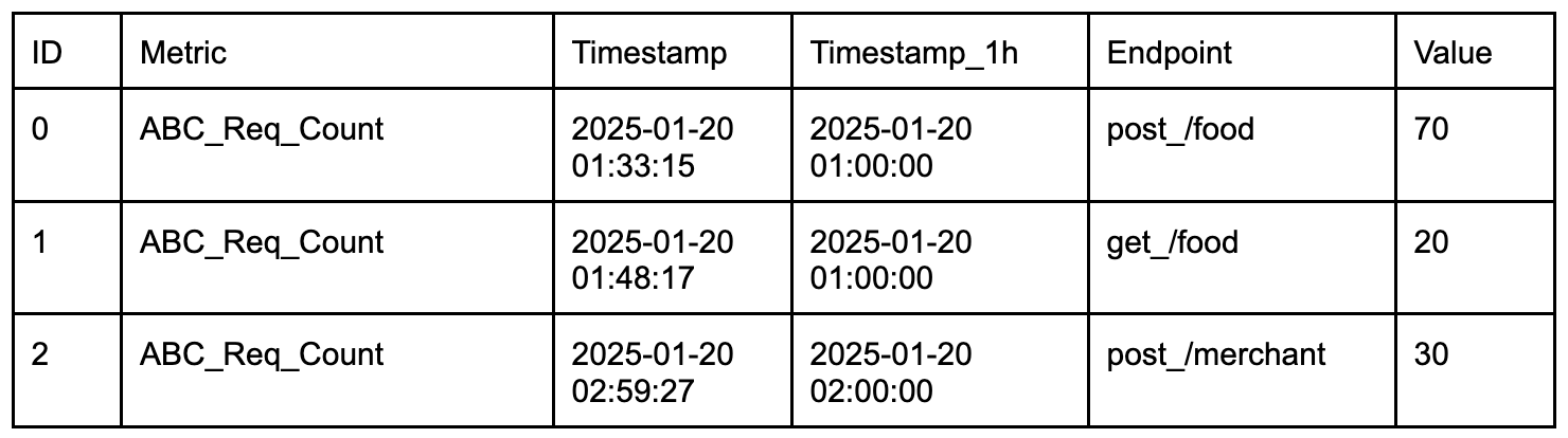
The evolution of Grab’s machine learning feature store

Post Syndicated from Grab Tech original https://engineering.grab.com/evolution-of-grab-machine-learning-feature-store

Introduction

In this post, we outline how we transformed the way we serve data for our machine learning (ML) models and why we chose Amazon Aurora Postgres as the storage layer for our new feature store. At Grab, we have always been at the forefront of leveraging technology to enhance our services and provide the best possible experience for our platform users. This journey has led us to transition from a traditional approach to a more sophisticated and efficient ML feature store.

Over the years, ML at Grab has progressed from being used for specific, tactical purposes to being utilised to create long-term business value. As the complexity of our systems and ML models increased, requiring richer amounts of data over time, our platforms faced new challenges in managing more complex features such as a large number of feature keys (high-cardinality) and high-dimensional data or vectors. This evolution necessitated a shift in our data processing and management strategy. We needed a system to store and manage these complex features efficiently. In November 2023, this brought us back to the drawing board to evolve from Amphawa, our initial feature store.

We landed on the concept of feature tables: a set of data lake tables for ML features that are automatically and atomically ingested into our serving layer. While this concept is not new to the industry, as other platforms like Databricks and Tecton have evolved towards it, our approach is focused on atomicity and reproducibility. The rationale is that ensuring consistency and reliability during the serving lifecycle has become more critical, which has made it more challenging to manage within the model serving layer itself.

From feature store to data serving

A feature store is a repository that stores, serves, and manages ML features. It provides a unified platform where data scientists can access and share features, reducing redundancy and ensuring consistency across different models.

Figure 1: The high-level architecture of our centralised feature platform.

Our feature data is a key-value dataset. The key identifies a specific entity, such as a consumer ID, which is a known value in the incoming request. A composite key is supported by concatenating two or more entity identifiers. For example, (key = consumer_id + restaurant_id). The value is a binary that encodes the feature value and its type. Whenever a new value for a given entity needs to be updated, we write a new key-value pair for that entity.

New functional requirements

As our users designed and deployed increasingly complex ML solutions, new essential functional requirements were requested by our users:

  • Ability to retrieve the features given in the composite keys (contextual retrieval): The ML models in an upstream service might need to fetch all matching entities to form complete contextual information in order to make the recommendation. We build that context inside our ML orchestration layer before calling the model. This was previously not possible due to the design of composite keys in our initial approach.
  • Ability to update not just one entity atomically, but all the entities in a collection (atomic updates): This requirement concerns reducing the complexity of operations, such as rolling out new models and switching between versions of feature data. In Amphawa, newly ingested data is visible to consumer systems immediately after it’s written. As changes to the data may be ingested over a long period of time, users are responsible for ensuring the models or services don’t break while the new and old data coexist during ingestion, especially during potentially breaking changes to data. This complexity translates into quite complex code, which is hard to refactor over time. With the new approach, all feature changes will only become visible through atomic updates once the entire operation finishes successfully. This eases users’ pain of maintaining compatibility across versions.
  • Isolation of reading and writing capacity: The noisy-neighbor effect is one of the significant issues in our centralised feature store. Different readers could compete for read capacity. For some storage systems, write traffic could consume I/O capacity and affect reading latency. While reading capacity can be adjusted by scaling the storage, the competition between reading and writing capacity is highly dependent on the choice of storage. Hence, from the beginning, one of the top requirements of our second-generation feature store design was isolating reads from writes.

Feature table

To meet the functional requirements, we landed on the concept of a “feature table,” where users define and manage the schema and data on a per-table basis. Feature consumers can customise their tables based on their needs. Working with a table format directly makes it easier for data scientists to work with complex tabular data that needs to be retrieved in different ways depending on the context of the request. Moreover, it’s more manageable for us, on the platform side, because it’s closer to the actual format in the storage layer.

Amphawa (feature-centric) New design (feature-table centric)
A user defines individual features and their types. Grouping into the table is storage layer is implicit. A user defines their tables with compatibility with data-lake tools such as Spark.
The only index is on the data key. A user defines their own indexes for their tables, based on their access pattern.
Table 1: Comparison between Amphawa and the new feature table.

Our feature tables are not just a storage solution but a critical component of our ML infrastructure. They enable us to simplify our feature management, efficiently handle the model lifecycle, and enhance our ML models’ performance. This has allowed us to provide a better experience for our platform users and dramatically improve the quality of our ML models based on our A/B testing results.

The data serving’s ingestion workflow

We designed an ingestion framework to address the atomicity requirements from the ground up.

The data ingestion process in Amphawa was meticulously crafted to ensure efficiency and reduce the pressure on the key-value store. Conversely, our priority has shifted to atomicity (all or nothing) to serve our feature tables and simplify version compatibility.

Figure 2: Ingestion workflow.
  • Landing feature table in the data lake: Data scientists use SQL or Python on Spark to build ML pipelines that output data lake tables. These tables and metadata for version control are stored as Parquet objects in Amazon S3.
  • Register collection summary: A “collection summary” consists of a group of feature tables to be served and other related metadata regarding customised individual tables. In this step, our registry will validate the table’s schema and ensure the customisations are defined correctly.
  • Deploy collection summary: Data scientists send another request to our registry to deploy a collection summary.
  • Pre-ingestion validation: The schema is validated to ensure compatibility with the target online ML models. This process ensures consistency and compatibility across feature updates.
  • Ingestion: The ingestion mechanism is a classic reverse ETL where the data from S3 is loaded into our Aurora Postgres tables.
  • Post-ingestion warm-up: To avoid cold-start latency spikes, shadow reading duplicates a part of the ongoing reading queries to the new tables for a period before the final switch.

One of the core propositions of feature tables is to offer a simplified interface for writing. Compared to writing directly to a database or providing SDKs for different processing frameworks, we provide a single, common interface for writing, independent of the actual choice of database. This allows us to evolve or even integrate feature tables with other data stores without requiring our users to modify their pipelines. We can decide how the data is represented in the database at a specific isolation level while guaranteeing total transparency for writes and reducing the complexity of read operations.

However, if a producer has access to S3 and can write in a columnar format, they can always write feature tables. This also means they can access samples from the data lake and use other tools for data validation, as well as tools for data discovery.

Do take note that a feature table can only be used for data that can be represented in tabular format and requires a minimum of one index to be present in the data. In this initial phase, we support the following data types:

  • Atomic types (int, long, boolean, string, float, double)
  • List of atomic types (List[atomic])
  • List of list of atomic types (2d array)
  • Dictionary with strict types of keys and values

Leveraging AWS Aurora for Postgres to meet our non-functional requirements

In our quest to optimise our ML infrastructure, we strategically decided to use Amazon Web Services (AWS) Aurora for PostgreSQL to meet our non-functional requirements. Aurora’s unique features and capabilities, which aligned perfectly with our operational needs, drove this decision.

AWS Aurora is a fully managed relational database service that combines the speed and reliability of high-end commercial databases with the simplicity and cost-effectiveness of open-source databases. A key differentiator is Aurora’s distributed storage architecture.

Figure 3: AWS Aurora storage architecture.

Architecture breakdown

The cluster volume consists of copies of the data across three “Availability Zones” in a single AWS Region. Since each database instance in the cluster reads from the distributed storage, this allows for minimal replication lag and ease of scaling out read replicas to meet performance requirements as traffic patterns change.

The separation between readers and writers also allows us to scale each independently. This is a crucial feature as our traffic is predominantly read-heavy. Most of our data-writes occur once a day. Using a serverless instance class with the writer node being scaled down during idle time significantly reduces our overall operational costs.

The independent scaling of reader and writer nodes allows us to maintain high performance and availability of our feature store. During peak read times, we can scale out the reader nodes to handle the increased load, ensuring that our ML models have uninterrupted access to the features they need. Conversely, during periods of heavy data ingestion, we can scale up the writer nodes to ensure efficient data storage.

To facilitate the seamless scaling up and down of the writer node, Aurora also allows a cluster to have a mixture of Serverless and Provisioned nodes. The key difference between the two is that with Serverless, the Aurora service manages the capacity of a single node and adjusts accordingly as the load increases and decreases. In our context, we’re using Serverless for our writer node to quickly scale up when heavy data ingestion starts and scale down automatically once the ingestion is done. We then use Provisioned nodes for the reader nodes since read traffic is more consistent.

In addition to cost and performance benefits, AWS Aurora simplifies our database management tasks. As a fully managed service, Aurora takes care of time-consuming database administration tasks such as hardware provisioning, software patching, setup, configuration, or backups, allowing our team to focus on optimising our ML models.

Accessing the data through our SDK

With the goal of providing a high-performing and highly available data serving SDK design, we’ve moved on from the centralised API design of Amphawa to a decentralised access architecture in Data Serving. Each data serving deployment is a self-contained system with a cluster and feature catalogue stored within the cluster as additional metadata tables. This minimises dependency, which improves the availability of the system.

The data serving SDK is designed to be a thin wrapper around the database driver to optimise performance. The SDK contains only a set of utility functions that load user configuration from the Catwalk platform and a query builder to translate user queries to SQL. No additional data validation is performed in the query code path, as all validation is done during feature table generation and ingestion. Therefore, the database handles most of the heavy lifting.

Decentralised deployments: A strategic shift in our infrastructure

We also investigated the difference between centralised and decentralised deployments. We have been exploring these options in the context of our ML feature store, specifically with our Amphawa service and Catwalk orchestrators.

Our original feature store was deployed as a standalone service where different model-serving applications can connect to it. On the other hand, a decentralised deployment is integrated within a model-serving orchestrator, and a specific orchestrator is bound to a set of pods.

After extensive discussions and evaluations, we concluded that a decentralised deployment for data serving would better align with our operational needs and objectives. Below is the list of factors we compared that led us to this decision:

  • Version control: Centralised deployments simplify version control but risk accumulating technical debt due to backward compatibility requirements. Decentralised deployments, while needing robust tracking, offer more flexibility.
  • Deployment strategies: Decentralised deployments enabled seamless use of Blue-green and Rolling Deployment strategies. They allow multiple versions to coexist and easy rollbacks, reducing client mismatch issues.
  • Noisy neighbour problem: Centralised deployments struggle with the noisy neighbour issue, which requires complex rate limiting. Decentralised setups mitigate this problem by isolating services.
  • Caching efficiency: Centralised deployments often suffer low cache hits, whereas decentralised deployments improve caching efficiency by better fitting data into the cache.

Conclusion

In conclusion, leveraging AWS Aurora for Postgres has enabled us to create a robust, scalable, and cost-effective feature store that supports our complex ML infrastructure. This is a testament to our commitment to using cutting-edge technology to enhance our services and provide the best possible experience for our users. Our shift towards decentralised deployments represents our dedication to optimising our infrastructure to support our ML models effectively. By aligning our deployment strategy with our operational needs, we aim to enhance the performance of our services and provide the best possible experience for our users.

Join us

Grab is a leading superapp in Southeast Asia, operating across the deliveries, mobility and digital financial services sectors. Serving over 800 cities in eight Southeast Asian countries, Grab enables millions of people everyday to order food or groceries, send packages, hail a ride or taxi, pay for online purchases or access services such as lending and insurance, all through a single app. Grab was founded in 2012 with the mission to drive Southeast Asia forward by creating economic empowerment for everyone. Grab strives to serve a triple bottom line – we aim to simultaneously deliver financial performance for our shareholders and have a positive social impact, which includes economic empowerment for millions of people in the region, while mitigating our environmental footprint.

Powered by technology and driven by heart, our mission is to drive Southeast Asia forward by creating economic empowerment for everyone. If this mission speaks to you, join our team today!
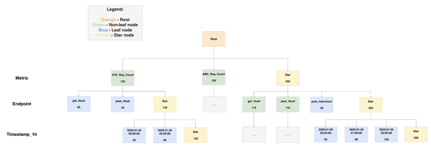
Grab’s service mesh evolution: From Consul to Istio

Post Syndicated from Grab Tech original https://engineering.grab.com/service-mesh-evolution

The challenge: When good enough isn’t good enough

Picture this: It’s 2024, and Grab’s microservices ecosystem is thriving with over 1000 services running in different infrastructure. But behind the scenes, our service mesh setup is showing its age. We’re running Consul with a fallback mechanism called Catcher – a setup that has served us well but is starting to feel like wearing a winter coat in Singapore’s heat.

The challenges we faced were becoming increasingly apparent. A single Consul server issue could trigger a fleet-wide impact, affecting critical services like food delivery and ride-hailing. Our fallback solution, while necessary, added complexity and limited our ability to implement advanced features like circuit breaking and retry policies. As we expanded our presence across Southeast Asia, the need for robust multi-cluster support became more critical than ever. The existing setup struggled with modern requirements like advanced traffic management and fine-grained security controls, while the growing complexity of our microservices architecture demanded better traffic management capabilities.

The complexity of Grab’s infrastructure

Our infrastructure landscape is as diverse as the Southeast Asian markets we serve. We operate a complex hybrid environment encompassing services on traditional VMs and EKS clusters with diverse infrastructure provisioning and deployment approaches. This diversity isn’t merely about deployment models—it’s about meeting the unique needs of different business units and regulatory requirements across the region.

The complexity doesn’t stop there. We handle dual traffic protocols (HTTP and gRPC) across our entire service ecosystem. Our services communicate across cloud providers between AWS and GCP. Within AWS alone, we maintain multiple organizations to segregate different Grab entities, each operating in its own isolated network. This multi-cloud, multi-protocol, multi-organization setup presented unique challenges for our service mesh implementation.

The quest for a better solution

Like any good tech team, we didn’t just jump to conclusions. We embarked on a thorough evaluation of service mesh solutions, considering various options including Application Load Balancer (ALB), Istio, AWS Lattice, and Linkerd. Our evaluation process was comprehensive and focused on real-world needs, examining everything from stability under high load to the performance impact on service-to-service communication.

We needed a solution that could handle our distributed architecture while maintaining operational simplicity. The ideal service mesh would need to integrate seamlessly with our existing infrastructure landscape while offering the flexibility to scale with our growing needs. After careful consideration, Istio emerged as the clear winner, offering robust multi-cluster support with flexible deployment models and a comprehensive set of features for traffic management, security, and observability.

What really sealed the deal was Istio’s strong Kubernetes integration and native support, combined with active community backing. The rich ecosystem of tools and integrations meant we wouldn’t be building everything from scratch, while the flexible deployment options could accommodate our unique requirements.

Designing our Istio architecture

When it came to designing our Istio implementation, we took a slightly unconventional approach. Instead of following the traditional “one control plane per cluster” pattern, we designed a more resilient architecture that would better suit our needs. We implemented multiple control planes running on dedicated Kubernetes clusters for better isolation and scalability, with active-active pairs ensuring high availability.

Figure 1. External control planes and Kubernetes API servers – Endpoints discovery
Figure 2. Istio proxy to Istio control plane – xDS flow

Our architecture needed to support high-throughput service-to-service communication while enabling complex routing rules for A/B testing and canary deployments. We implemented custom resource definitions for service mesh configuration and integrated with our existing monitoring and alerting systems. The organization-based mesh boundaries we designed would support our multi-tenant architecture, while our solution for cross-cluster endpoint discovery would ensure reliable service communication across our distributed system.

This design wasn’t just about following best practices – it was about learning from our past experiences with etcd and Consul. We wanted a setup that could handle Grab’s scale while maintaining simplicity and reliability. The architecture needed to support everything from high-throughput service-to-service communication to complex routing rules for A/B testing and canary deployments, all while maintaining fine-grained security policies and comprehensive observability.

The migration journey begins

In Q4 2024, we kicked off our migration journey with a clear plan. While our initial strategy focused on gRPC traffic migration, real-world priorities led us down a different path. Our first major milestone was the GCP to AWS migration, a cross-cloud initiative that would test our service mesh capabilities in a complex, multi-cloud environment.

This cross-cloud migration was a significant undertaking, requiring careful coordination between teams and careful consideration of network policies, security requirements, and service dependencies. We had to ensure seamless communication between services running in different cloud providers while maintaining security and performance standards.

Alongside our ongoing cloud migration efforts, we launched parallel initiatives focused on gRPC and HTTP traffic migration with cross-mesh connectivity requirements. This phase introduced distinct challenges, as it involved migrating business-critical services while implementing gradual traffic shifting capabilities and quick rollback mechanisms to ensure zero-downtime migrations. We also maintained close monitoring of performance metrics throughout the process.

Additionally, we needed to ensure seamless compatibility between different service mesh implementations and navigate the complexities of cross-mesh communication. The insights and experience gained from our cloud migration phase have proven invaluable in informing our approach and execution strategy for this critical migration effort.

The journey hasn’t been without its challenges. We’ve had to balance migration speed with stability while coordinating across multiple teams and organizations. Handling both gRPC and HTTP traffic patterns required careful planning and execution. We’ve had to deal with legacy systems and technical debt while training and supporting teams through the transition. Maintaining service continuity during these transitions has been our top priority.

Lessons learned

This journey has taught us several valuable lessons. We’ve learned that sometimes the standard approach isn’t the best fit, and innovation often comes from questioning assumptions. We’ve discovered the importance of balancing innovation with stability, taking calculated risks while building capability for a quick mitigation.

Keeping the bigger picture in mind has been crucial, considering long-term implications and planning for scale and growth. We’ve learned to document challenges and solutions, sharing knowledge across teams to avoid repeating mistakes. Most importantly, we’ve learned to stay flexible and adapt to changing needs, being ready to pivot when necessary while keeping an eye on emerging technologies.

What’s next?

The service mesh landscape is constantly evolving, and we’re excited to be part of this journey. Our next steps include continuing our migration efforts with a focus on stability while exploring mesh features like advanced traffic management, and enhanced security policies.

We’re also working on enhancing our operational capabilities through automated testing and validation, improved monitoring and alerting, and better debugging tools. As we progress, we’re committed to sharing our experiences with the community through open source contributions, conference participation, and technical blogs.

Shape the future with us

We’re not just implementing a service mesh—we’re architecting the backbone of Grab’s microservices future. Every decision prioritizes reliability, scalability, and maintainability, ensuring we build something that will stand the test of time.

The journey continues, and we’re excited about what lies ahead. Follow our progress for real-world insights that might shape your own service mesh evolution.

Want to help us build the future? We have exciting opportunities waiting for you.

Credits to the Service Mesh team: Aashif Bari, Hilman Kurniawan, Hofid Mashudi, Jingshan Pang, Kaitong Guo, Mikko Turpeinen, Sok Ann Yap, Jesse Nguyen, and Xing Yii.

Join us

Grab is a leading superapp in Southeast Asia, operating across the deliveries, mobility and digital financial services sectors. Serving over 800 cities in eight Southeast Asian countries, Grab enables millions of people everyday to order food or groceries, send packages, hail a ride or taxi, pay for online purchases or access services such as lending and insurance, all through a single app. Grab was founded in 2012 with the mission to drive Southeast Asia forward by creating economic empowerment for everyone. Grab strives to serve a triple bottom line – we aim to simultaneously deliver financial performance for our shareholders and have a positive social impact, which includes economic empowerment for millions of people in the region, while mitigating our environmental footprint.

Powered by technology and driven by heart, our mission is to drive Southeast Asia forward by creating economic empowerment for everyone. If this mission speaks to you, join our team today!
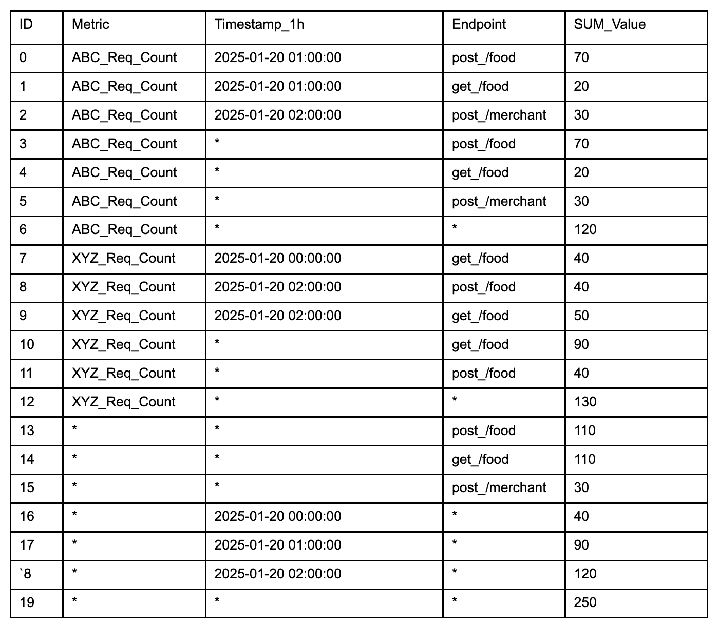
DispatchGym: Grab’s reinforcement learning research framework

Post Syndicated from Grab Tech original https://engineering.grab.com/techblog_-dispatchgym

Introduction

DispatchGym is a research framework designed to facilitate Reinforcement Learning (RL) studies and applications for the dispatch system, which matches bookings with drivers. The primary goal is to empower data scientists with a tool that allows them to independently develop and test RL-related concepts for dispatching systems. It accelerates research by providing a suite of modules that include a reinforcement learning algorithm, a dispatching process simulation, and an interface connecting the two through the Gymnasium API.

To ensure efficient and cost-effective RL research without compromising on quality, DispatchGym aims to be both comprehensive and accessible. Anyone with basic RL knowledge and Python programming skills can use it to explore new ideas in RL and dispatch system logic.

This article walks you through the principles behind DispatchGym, how these principles effectively and efficiently empower impactful research, and how it can be applied to solve real world problems.

The challenge with RL

Although RL methods can be applied to a wide variety of problems that can be formulated as a Markov Decision Process (MDP), designing an effective RL-based solution is not a trivial task. The primary challenges stem from two key components: the reward function and the lever.

In RL, the reward function represents the objective we aim to maximize. At first glance, it might seem straightforward to plug in any metric, such as the company’s profit or the number of completed bookings per day. However, these metrics are not always sensitive to the lever that RL can manipulate, or the lever itself may not significantly influence the objective. For example, consider a setup where we aim to maximize the daily number of completed bookings by adjusting the maximum number of candidate drivers considered to each booking. Beyond a minimal threshold (e.g., one driver), further increasing this limit provides negligible benefits. As a result, RL struggles to determine whether setting this limit to 11 or 15 would result in higher rewards.

In summary, when a lever exerts weak influence on a reward function, the RL setup becomes ineffective. Therefore, we should strive to select a lever that strongly influences the reward function and define a reward function that is both sensitive to manipulations of that lever and aligned with our overall goal. Note that the reward function does not have to be identical to our ultimate objective; it merely needs to be highly correlated with it.

Figure 1. Illustration of weak lever influence on a reward function.

Empowering research with DispatchGym

The primary application of DispatchGym is to accelerate and broaden cost-effective research and impactful RL applications for Grab’s dispatching system. A system which is responsible for assigning a driver to each booking. To achieve this, DispatchGym must have the following characteristics:

  • Reliable
    The simulation component should be accurate enough to capture essential behaviors strongly linked to the metrics of interest, without necessarily modeling everything else. While it’s beneficial if the simulation can do more than the specific use case (e.g., simulating both batching and allocation when only allocation is needed), it is not strictly required.

  • Cost-effective
    Updating all of DispatchGym’s components should require minimal monetary and labor costs to enable rapid iteration. This includes keeping the simulation component aligned with real system behaviors, incorporating the latest technologies in the optimization component, and maintaining seamless integration between the simulation and optimization components.

  • Empowering
    It should be as easy as possible for data scientists and engineers to modify any DispatchGym component and then run experiments. This flexibility is crucial because new research typically requires adjustments to both the simulation and optimization components. By granting users the freedom to adapt DispatchGym, the framework fosters continuous innovation.

Research-friendly simulated environment

The simulation component of DispatchGym, or the “simulated environment,” is designed with reliability, cost-effectiveness, and user empowerment in mind. It models the full dispatching process, from booking creation and driver dispatch to driver movement and booking completion. While this environment may not be perfectly accurate in absolute terms (there can be differences between real and simulated metric values), it emphasizes directional accuracy. This means that the metric trends (up or down) in the simulation closely match real-world behavior. This focus on directional accuracy is crucial because most research involves sim-to-sim comparisons, where shifts in metrics are the most important. Verifying directional accuracy is also simpler and more practical for evaluating simulation performance. For instance, we can test various supply-demand imbalance scenarios and check whether a supply-rich situation indeed fulfills more bookings, and vice versa.

Figure 2. Simulated processes.

The simulated environment’s cost-effectiveness and empowerment features come from a modular architecture and Python, a research-friendly programming language. The modular design offers a gentle learning curve, allowing users to easily navigate and make necessary changes in the codebase. Meanwhile, Python is selected to lower the entry barrier for adopting DispatchGym. To mitigate Python’s runtime overhead, DispatchGym leverages Numba to significantly speed up simulation execution.

DispatchGym in action

Data scientists use DispatchGym by modifying a local copy of the codebase to implement their ideas. They then upload the updated codebase to an internal infrastructure using a single CLI command, which spawns a Spark job to run the DispatchGym program. This setup grants complete flexibility over the simulation and optimization components without requiring users to manage the underlying infrastructure.

Figure 3. Data scientist interactions with DispatchGym.

Applying RL approach for dispatch

Amongst its many uses, DispatchGym was applied in building an effective contextual bandit strategy for the auto-adaptive tuning of dispatch-related hyperparameters. Its flexibility allowed us to experiment with various contextual bandit model variants, including linear bandits, neural-linear bandits, and Gaussian-process bandits, as well as multiple action sampling strategies, such as epsilon-greedy, Thompson sampling, SquareCB, and FastCB. These capabilities accelerated our progress in determining the best combination of levers, reward functions, and contextual bandits for improved fulfilment efficiency and reliability.

Conclusion

DispatchGym provides us a framework that equips data scientists with everything they need to develop and test RL solutions for dispatch systems. By integrating an RL optimization approach and a realistic dispatch simulation using a Gymnasium API, it enables rapid exploration and iteration of RL applications with just basic RL knowledge and Python programming language.

A major hurdle in applying RL to dispatch problems modeled as MDP is ensuring that the reward function aligns with ultimate business goals and is sensitive to the lever under control. If the lever (e.g., tweaking driver count) does not meaningfully influence the reward, the RL approach falters. DispatchGym addresses this by making it easy for data scientists to determine the most effective combinations of levers, reward functions, and RL approaches, ultimately driving positive business impact.

DispatchGym’s architecture focuses on reliability, cost-effectiveness, and user empowerment. Its simulation is designed to capture critical metrics and reflect real-world trends (directional accuracy), while its Python-based modular design enhanced by Numba enables easy prototyping. Researchers can adjust the environment locally before deploying changes seamlessly via a command-line interface, avoiding infrastructure overhead. These design decisions and capabilities empower data scientists to refine contextual bandit approaches for optimizing dispatch hyperparameters and explore innovative RL applications in the dispatch process.

We would like to thank Chongyu Zhou, Guowei Wong, and Roman Kotelnikov for their collaboration in developing the RL-based optimizer.

Join us

Grab is a leading superapp in Southeast Asia, operating across the deliveries, mobility and digital financial services sectors. Serving over 800 cities in eight Southeast Asian countries, Grab enables millions of people everyday to order food or groceries, send packages, hail a ride or taxi, pay for online purchases or access services such as lending and insurance, all through a single app. Grab was founded in 2012 with the mission to drive Southeast Asia forward by creating economic empowerment for everyone. Grab strives to serve a triple bottom line – we aim to simultaneously deliver financial performance for our shareholders and have a positive social impact, which includes economic empowerment for millions of people in the region, while mitigating our environmental footprint.

Powered by technology and driven by heart, our mission is to drive Southeast Asia forward by creating economic empowerment for everyone. If this mission speaks to you, join our team today!
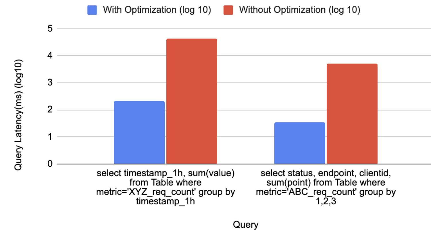
Counter Service: How we rewrote it in Rust

Post Syndicated from Grab Tech original https://engineering.grab.com/counter-service-how-we-rewrote-it-in-rust

Abstract

The Integrity Data Platform (IDP) team decided to rewrite one of our heavy Queries Per Second (QPS) Golang microservices in Rust. It resulted in 70% infrastructure savings at a similar performance, but was not without its pitfalls. This article will elaborate on:

  • How we picked what to rewrite in Rust.
  • Approach taken to tackle the rewrite.
  • The pitfalls and speed bumps along the way.
  • Was it worthwhile?

Introduction

Grab is predominantly based on a microservice architecture, with the vast majority of microservices being hosted in a monorepo and written in Golang. It has served the company well so far, as the “simplicity” of Golang allows developers to ramp up and iterate quickly.

However, Rust has seen some gradual adoption across the company. Starting with a few minor CLIs, which then progressed to notable success with a Rust-based reverse proxy in Catwalk for model serving. Additionally, a growing community of Rust enthusiasts within the organisation has expressed interest in advocating for and expanding the adoption of Rust more proactively.

After achieving success with several projects on the ML platform and addressing concerns about Rust’s ability to handle traffic at scale, the next logical step was to assess the Return on Investment (ROI) of rewriting a Golang microservice in Rust.

Background

Rust has the reputation of being highly efficient yet poses a steep learning curve. Rust is often touted to perform close to C, doing away with garbage collection while remaining memory safe through strict compile checks and the borrow checker. It is loved by developers for having rich features like being multi-paradigm (supporting both functional and OOP style), having a rich type system, and doing away with nil pointers and errors.

However, regardless of how well regarded a certain language is in the industry, rewrites of any system should always be considered very carefully. When it comes to “legacy software”, there is a prevalent assumption that rewriting legacy software is a solution to eliminate technical debt and phase out legacy systems. The reality is often more nuanced.

Legacy code occurs when the developers who originally wrote the code are no longer working on the project. There are often business logic and edge-cases baked into complex legacy codebases of which the context has been lost over time. In practice, rewrites frequently take longer than anticipated and tend to reintroduce bugs and edge cases that must be identified and resolved all over again.

Rewriting vs refactoring has been written at length across the internet, you can read more about it here.

The trade-offs of rewriting need to be properly weighed and balanced. It must take into consideration:

  • How much engineering bandwidth goes into the rewrite?
  • What is the complexity of the rewrite?
  • What tangible benefits are brought about by the rewrite?

Rewriting a system solely for the purpose of “rewriting it in Rust” is not a strong enough business justification.

A legitimate concern was the steep learning curve of Rust, coupled with the risk of having only one team member proficient in the language, which would make its adoption unsustainable.

Therefore, we established a set of guidelines to follow when identifying a suitable system for a potential rewrite:

  • The system must be “simple” enough in functionality. For example, it has one or two main functionalities that can be rewritten in a reasonable amount of time and have its complexity constrained.
  • The system targeted should have large enough traffic such that cost savings brought about by adopting Rust is something tangible when balanced against the effort.
  • The members of the team must be comfortable and willing to pick up the language and achieve a certain level of familiarity to make maintaining the service sustainable.

Finding the right service

The ideal service should have a sufficiently large infrastructure footprint to justify the potential cost savings, while also being straightforward in functionality to minimise time spent on handling edge cases and complex business logic.

Looking across the stack of microservices in Integrity, Counter Service stands out. As its name implies, Counter Service is a service that “counts” and serves the counters for ML models and fraud rules. The original service has two primary functionalities:

  • Consuming from streams, counting events and writing to Scylla.
  • Exposing Google Remote Procedure Call (GRPC) endpoints to query from Scylla (and Redis) and return counts of events based on query keys. For example, BatchRead. BatchRead’s functionality of Counter Service serves up to tens of thousands of QPS at peak and is fairly constrained in functionality. Hence, it fulfilled our target criteria of being “simple” in functionality yet serving a large enough amount of traffic that justifies the ROI of a rewrite.
Figure 1: BatchRead flow of Counter Service, reading data from Scylla, DynamoDB, Redis, MySQL and serving the counters through GRPC.

Rewrite approach

There are a few ways to approach a rewrite in another language. One popular way is to convert your code line by line. If the languages are close enough, it might even be possible to programmatically convert your code like C2Rust.

We decided not to use such an approach for our rewrite. The major reason is that idiomatic Golang was not necessarily idiomatic Rust. We wanted to approach this rewrite with a fresh perspective and treat this as a true rewrite.

We treated the application like a black box, with the interfaces well defined, like GRPC endpoints and contracts. Similar to a function, you could call the API and get a deterministic result, and we had the data that was stored in Scylla.

Based on how we understood the application to work based on its specs and contract, we chose to rewrite the application logic from scratch to meet the API contract and to get as close as identical outputs from the new black box.

OSS library support

We started out by mapping out the key external dependencies and checking how well they were supported in the Rust ecosystem and in open source.

Table 1: List of libraries and their star ratings
Functionality Library Stars (as of Nov 24)
Datadog (Statsd Client) https://github.com/56quarters/cadence < 500
Lightstep (OpenTelemetry) https://github.com/56quarters/cadence > 1000
GRPC Server https://github.com/hyperium/tonic > 500
Web Server https://github.com/actix/actix-web > 20,000
Redis Client https://github.com/aembke/fred.rs (Async Redis Library + Client pool) > 5000
Redis Client https://github.com/redis-rs/redis-rs (“Official” redis client, initially picked but discarded) > 3000
Scylla Client https://github.com/scylladb/scylla-rust-driver ~500
Kafka Client https://github.com/kafka-rust/kafka-rust >1000

All the functionality we need is available through libraries in the Rust ecosystem. However, we found that some libraries are not particularly “popular,” as indicated by their relatively low number of GitHub stars.

The practical concern with using less “popular” libraries is the risk of limited community support or potential abandonment over time. That said, if an “unpopular” library is officially maintained by the associated open-source project—for instance, the Scylla driver has only about 500 stars but is officially provided by the Scylla project—we would need to ensure confidence that it will continue to receive active support.

Out of the list of libraries above, the “unpopular” and unofficial libraries can be narrowed down to two libraries:

  • Datadog – Cadence
  • Redis – Fred

For Datadog, there is no “official” Datadog Rust client. Yet, we picked Cadence as the API looked intuitive and the features we needed were already supported.

In regards to Redis, after testing it, we discovered that the support was not up to par with our requirements. We then opted for a newer and less popular library, fred.rs that seemed to be actively being developed by the community.

Company specific internal libraries

With the vast majority of microservices being written in Golang, most internal libraries are also written in Golang. Opting to rewrite a service in Rust means we are not able to use these internal libraries.

Examples include:

  • An internal configuration library that utilises Go Templates to template configurations for different environments (staging and production).
  • The internal configuration library has its own wrappers and injectors to pull and render secrets.

To overcome this gap and re-use Go Templates and configuration language, we decided to write a simple wrapper and parser using the nom parser combinator to parse the templates and render the config.

Nom poses a steep learning curve. But once familiarised, it is flexible and performant enough to build an equivalent to the internal library. Parser combinators are an interesting subset of tooling that allows you to create some fairly elegant parsers.

Road bumps

The borrow checker

One of the most striking paradigm shifts for developers transitioning to Rust is adapting to the strict rules of the borrow checker, which enforces that variables cannot be reused multiple times unless explicitly cloned or borrowed.

Interestingly, the borrow checker was not the biggest hurdle for new developers. The key is to avoid introducing lifetimes too early in the development process, as this can lead to premature code optimisation.

In many cases, adding a few clones (and occasionally Arcs) can help new developers get up to speed and iterate more quickly during development. The resulting code is usually “fast” enough for initial purposes. After that, the code can be revisited to eliminate unnecessary clones for improved performance. An efficient approach to this can be taken by using Flamegraph to profile your code and identify memory allocation bottlenecks.

Async gotchas

When rewriting Golang logic in Rust, there are fundamental differences in how they treat concurrency and parallelism.

One of Golang’s most remarkable strengths is its ability to deliver high-performance concurrency while preserving simplicity.

There are two fundamental approaches to concurrency in programming languages, namely:

  • Preemptive scheduling (stackful coroutines).
  • Cooperative scheduling (stackless coroutines).

Preemptive vs cooperative scheduling is an in-depth topic with the gist of it being, Golang uses preemptive scheduling and each “Goroutine” has a stack that needs a runtime. The Golang scheduler has the power to “preempt” and “freeze” functions and switch to another stack like stackful coroutine. This is a gross oversimplification of the nuances. For more details, this is a good introduction to the topic.

Rust opts for cooperative scheduling whereby it has no runtime and each coroutine does not maintain a stack. Hence, it has no ability to “freeze” a function and swap context. This allows Rust to be more efficient in terms of memory and resources, as it maintains a state machine. However, the consequence is that this moves the complexity up the stack to the programming language itself. Similar to Javascript, functions are “coloured”, and the developer has to explicitly annotate their functions to be async or sync. Await points need to be explicitly called and control needs to be “yielded” (i.e. cooperative and stackless) so the Rust program knows when it is allowed to stop and swap between coroutines. To read more on this, refer to this and this article for the history of async Rust.

Needing to annotate a function is a classic complaint that is addressed in the article “What Colour is Your Function” that highlights developers’ responsibility to explicitly colour their function and consciously think about blocking vs non-blocking code.

Contrast this with Golang, where you simply need to add the go keyword without thinking about which code might block the execution and use channels to communicate across Goroutines. Golang allows the developer to achieve high performance without much cognitive overhead.

This is especially important for developers new to Rust. As the lack of experience in async and blocking code can be somewhat of a footgun. In the initial rewrite of Rust, we made an amateur mistake of using a synchronous Redis function to call the Redis cache. It resulted in the application performing poorly until we corrected it with the non-blocking asynchronous version using the Fred redis library.

Impact

Following the eventful process of rewriting the service from the ground up in Rust, the outcomes proved to be quite intriguing.

Shadowing traffic to both services as seen in Figure 2, the P99 latency is similar (or perhaps even slightly worse) in the Rust service compared to the original Golang one.

Figure 2: P99 latency comparison between the Golang service (purple) and Rust service (blue).

Normalising the QPS and resource consumption, we see from Table 2 that Rust consumes ~20% of the resources of the original Golang application, resulting in 5x savings in terms of resource consumption.

Table 2: Comparison of resource consumption between Rust and Golang service.
Service Indicative QPS Resources
Original Golang Service 1,000 20 Cores
New Rust Service 1,000 4.5 Cores

Learnings and conclusion

The outcomes and insights from this rewrite have been eye-opening, debunking certain myths while also validating others.

Myth 1: Rust is blazingly fast! Faster than Golang!

Verdict: Disproved.
Golang is “fast enough” for most use cases. It’s a mature language built with concurrency at its core, and it performs exceptionally well in its intended domain. While Rust can outperform Golang due to its higher performance ceiling and finer-grained control, rewriting a Golang service in Rust solely for performance improvements is unlikely to yield significant benefits.

Myth 2: Rust is more efficient than Golang

Verdict: True.
Rewriting a Golang service in Rust will probably give you 50% savings in compute. Rust does fulfill its promise of being memory safe without garbage collection, allowing it to be one of the more efficient languages out there. This is in line with other discoveries in the market.

Myth 3: The learning curve of Rust is too high

Verdict: It depends.
Pure synchronous Rust is fine. As long as you don’t overcomplicate the code and only clone what is needed, it is mostly true. The language is easy enough to pick up for most experienced developers. Even with cloning sprinkled in, the code is usually “fast enough”. The compiler is a good teacher, the compiler error messages are amazing, and if your code compiles, it probably works. Also, the Clippy linter is amazing.

However, introducing async can be challenging. Async is something quite different from what you would encounter in other languages like Go. Improper use of blocking code in async code can result in nuanced bugs that can catch inexperienced Rust developers off-guard.

Evaluating the worth of the rewrite

Yes, the effort was worth it for this service. The trade-off between development effort spent and the cost savings were justified.

As a side effect, the service is 80% cheaper and probably more bug free, as Rust eliminates a class of common Golang errors like Null pointers and concurrent map writes by virtue of the design of the language. If your code compiles, you usually have the confidence that it will work as you expect due to the language being more explicit.

Would we encourage choosing Rust over Golang for new microservices? Absolutely, as the resulting service is likely to be at least 50% more efficient than its Go counterpart. However, this decision presents an important and exciting opportunity for management and leaders to invest in empowering their engineers by equipping them with the skills to master Rust’s unique concepts, such as Async and Lifetimes. While the initial development pace might be slower as the team builds proficiency, this investment can unlock long-term benefits. Once the workforce is skilled in Rust, development speed should align with expectations, and the resulting systems are likely to be more stable and secure, thanks to Rust’s inherent safety features.

Join us

Grab is a leading superapp in Southeast Asia, operating across the deliveries, mobility and digital financial services sectors. Serving over 800 cities in eight Southeast Asian countries, Grab enables millions of people everyday to order food or groceries, send packages, hail a ride or taxi, pay for online purchases or access services such as lending and insurance, all through a single app. Grab was founded in 2012 with the mission to drive Southeast Asia forward by creating economic empowerment for everyone. Grab strives to serve a triple bottom line – we aim to simultaneously deliver financial performance for our shareholders and have a positive social impact, which includes economic empowerment for millions of people in the region, while mitigating our environmental footprint.

Powered by technology and driven by heart, our mission is to drive Southeast Asia forward by creating economic empowerment for everyone. If this mission speaks to you, join our team today!
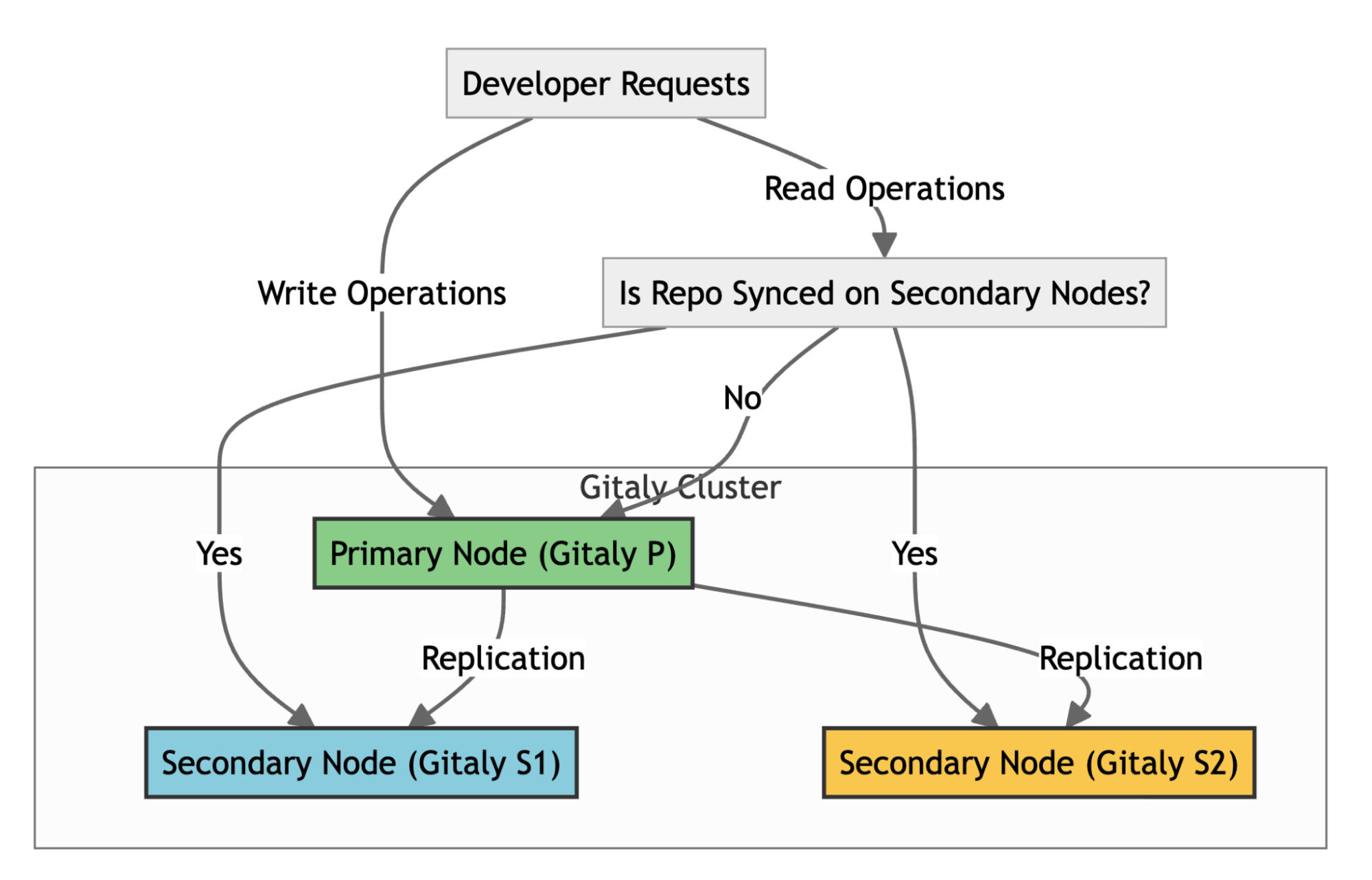
The complete stream processing journey on FlinkSQL

Post Syndicated from Grab Tech original https://engineering.grab.com/the-complete-stream-processing-journey-on-flinksql

Introduction

In the fast-paced world of data analytics, real-time processing has become a necessity. Modern businesses require insights not just quickly, but in real-time to make informed decisions and stay ahead of the competition. Apache Flink has emerged as a powerful tool in this domain, offering state-of-the-art stream processing capabilities. In this blog, we introduce our FlinkSQL interactive solution in accompanying productionising automation, and enhancing our users’ stream processing development journey.

Preface

Last year, we introduced Zeppelin notebooks for Flink, as detailed in our previous post Rethinking Stream Processing: Data Exploration in an effort to enhance data exploration for downstream data users. However, as our use cases evolved over time, we quickly hit a few technical roadblocks.

Zeppelin notebook source code is maintained by a community separate from Flink’s community. As of writing, the latest Flink version supported is 1.17, whilst the latest Flink is already on version 1.20. This discrepancy in version support hinders our Flink upgrading efforts.

Cluster start up time

Our design to spin up a Zeppelin cluster per user on demand invokes a cold start delay, taking roughly around 5 minutes for the notebook to be ready. This delay is not suitable for use cases that require quick insights from production data. We quickly noticed that the user uptake of this solution was not as high as we expected.

Integration challenges

Whilst Zeppelin notebooks were useful for serving individual developers, we experienced difficulty integrating it with other internal platforms. We designed Zeppelin to empower solo data explorers, but other internal platforms like dashboards or automated pipelines needed a way to aggregate data from Kafka and Zeppelin just couldn’t keep up. The notebook setup was too isolated, requiring a workaround to share insights or plug into existing tools. For instance, if a team wanted to pull aggregated real-time metrics into a monitoring system, they had to export data manually, which is far from seamless access that we aimed for.

Introducing FlinkSQL interactive

With those considerations in mind, we decided to swap out our Zeppelin cluster with a shared FlinkSQL gateway cluster. We simplified our solution by removing some features our notebooks offered, focusing only on features that promote data democratisation.

Figure 1: Shared FlinkSQL gateway architecture

We split our solution into 3 layers:

  • Compute layer
  • Integration layer
  • Query layer

Users first interact with our platform portal to submit queries for data from Kafka online store using SQL (1). Upon submission, our backend orchestrator then creates a session for the user (2) and submits the SQL query to our FlinkSQL gateway using their inbuilt REST API (3). The FlinkSQL gateway then packages the SQL query into a Flink job to be submitted to our Flink session cluster (4) before collating its results. The subsequent results would be polled from the query layer to be displayed back to the user.

Compute layer

With FlinkSQL gateway acting as the main compute engine for ad-hoc queries, it is now more straightforward to perform Flink version upgrades along with our solution, since the FlinkSQL gateway is packaged along with the main Flink distribution. We do not need to maintain Flink shims for each version as adapters between the Flink compute cluster and Zeppelin notebook cluster.

Another advantage of using the shared FlinkSQL gateway was the reduced cold start time for each ad-hoc queries. Since all users share the same FlinkSQL cluster instead of having their own Zeppelin cluster, there was no need to wait for cluster startup during initialisation of their sessions. This brought the lead time to the first results displayed down from 5 minutes to 1 minute. There was still lead time involved as the tool provisions task managers on an ad-hoc basis to balance availability of such developer tools and the associated cost.

Integration layer

The Integration layer serves as the glue between the user-facing query layer and the underlying compute layer, ensuring seamless communication and security across our ecosystem. With the shift to a shared FlinkSQL gateway, we recognised the need for an intermediary that could handle authentication, authorisation, orchestration, and integration with internal platforms – all while abstracting the complexities of Flink’s native REST API.

Figure 2: FlinkSQL gateway

The FlinkSQL gateway’s built-in REST API gets the job done for basic query submission, but it falls short in areas like session management, requiring multiple POST requests just to fetch results. To address this, we extended a custom control plane with its own set of REST APIs, layered on top of the gateway.

We then extend these sessions and integrate them to our inhouse authentication and authorisation platform. For each query made, the control plane authenticates the user, spins up lightweight sessions and manages the communication between the caller and the Flink Session Cluster. If you are interested, check out our previous blog post, An elegant platform, for more details on the above mentioned streaming platform and its control plane.

curl --location 'https://example.com/v1/flink/flinksql/interactive' \
--header 'Content-Type: application/json' \
--header 'Authorization: Bearer ...' \
--data '{
    "environment" : "prd",
    "namespace" : "flink",
    "sql" : "SELECT * FROM titanicstream"}'

Example API request for running a FlinkSQL query

The integration layer also caters to B2B needs via our Headless APIs. By exposing the endpoints, developers are able to integrate real-time processing into their own tools. To run a query, programs can simply make a POST request with the SQL query and an operation ID would be returned. This operation ID could then be used in subsequent GET requests to fetch the paginated results of the unbounded query. This setup is ideal for internal platforms that need to query Kafka data programmatically. By abstracting these complexities, it ensures that users, whether individual analysts or internal platforms—can tap into Kafka data without wrestling with Flink’s raw interfaces.

Query layer

We then proceed to pair our APIs developed with an Interactive UI to build a Query layer that serves both human workflows. This is where users meet our platform.

Figure 3: Flink query layer’s user flow

Through our platform portal, users land in a clean SQL editor. We used a Hive Metastore (HMS) catalog that translates Kafka topics into tables. Users don’t need to decode stream internals; they can jump straight into it by simply selecting a table to query on. Once a query is submitted, it is then handled by the integration layer which routes it through the control plane to the gateway. Results are then streamed back, appearing in the UI within one minute, a significant improvement from the five minute Zeppelin cold starts.

This all crystalises into the user flow demonstrated in Figure 3, where we can easily retrieve Titanic data from a Kafka stream with a short command:

SELECT COUNT(*) FROM titanicstream WHERE kafkaEventTime > NOW() - INTERVAL '1' HOUR.

This setup enables a few use cases for our teams, such as:

  • Fraud analysts using the real-time data to debug and spot patterns in fraudulent transactions.
  • Data scientists querying live signals to validate their prediction models.
  • Engineers validating the messages sent from their system to confirm they are properly structured and accurately delivered.

Productionising FlinkSQL

With data being democratised, we see more users building use cases around our online data store and utilising the above tools to build new stream processing pipelines expressed as SQL queries. To simplify the last step of the software development lifecycle of deployment, we have also developed a tool to create a configuration based stream processing pipeline, with the business logic expressed as a SQL statement.

Figure 4: Portal for FlinkSQL pipeline creation

We host connectors for users to connect to other platforms within Grab, such as Kafka and our internal feature stores. Users could simply use them off-the-shelf and configure according to their needs before deploying their stream processing pipeline.

Users would then proceed to submit their streaming logic as a SQL statement. In the example illustrated in the diagram, the logic expressed is a simple filter on a Kafka stream for sinking the filtered events into a separate Kafka stream.

Users have the ability to then define the parallelism and associated resources they want to run their Flink jobs with. Upon submission, the associated resources would be provisioned and the Flink pipeline would be automatically deployed. Behind the scenes, we manage the application JAR file that is being used to run the job that dynamically parses these configurations and translates them into a proper Flink job graph to be submitted to the Flink cluster.

Within 10 minutes, users would have completed deploying their stream processing pipeline to production.

Conclusion

With our full suite of solutions for low code development via FlinkSQL, from exploration and design, to development and then deployment, we have simplified the journey for developing business use cases off online streaming stores. By offering both a user-friendly interface for low-code users and a robust API for developers, these tools empower businesses to harness the full potential of real-time data processing. Whether you are a data analyst looking for quick insights or a developer integrating real-time analytics into your applications, our tools are able to lower the barrier of entry to utilising real-time data.

After we released these solutions, we quickly saw an uptick in pipelines created as well as the number of interactive queries fired. This result was encouraging and we hope that this would gradually bring upon a paradigm shift, enabling Grab to make data-driven operational decisions on real-time signals, empowering us with the ability to react to ever-changing market conditions in the most efficient manner.

Join us

Grab is a leading superapp in Southeast Asia, operating across the deliveries, mobility and digital financial services sectors. Serving over 800 cities in eight Southeast Asian countries, Grab enables millions of people everyday to order food or groceries, send packages, hail a ride or taxi, pay for online purchases or access services such as lending and insurance, all through a single app. Grab was founded in 2012 with the mission to drive Southeast Asia forward by creating economic empowerment for everyone. Grab strives to serve a triple bottom line – we aim to simultaneously deliver financial performance for our shareholders and have a positive social impact, which includes economic empowerment for millions of people in the region, while mitigating our environmental footprint.

Powered by technology and driven by heart, our mission is to drive Southeast Asia forward by creating economic empowerment for everyone. If this mission speaks to you, join our team today!
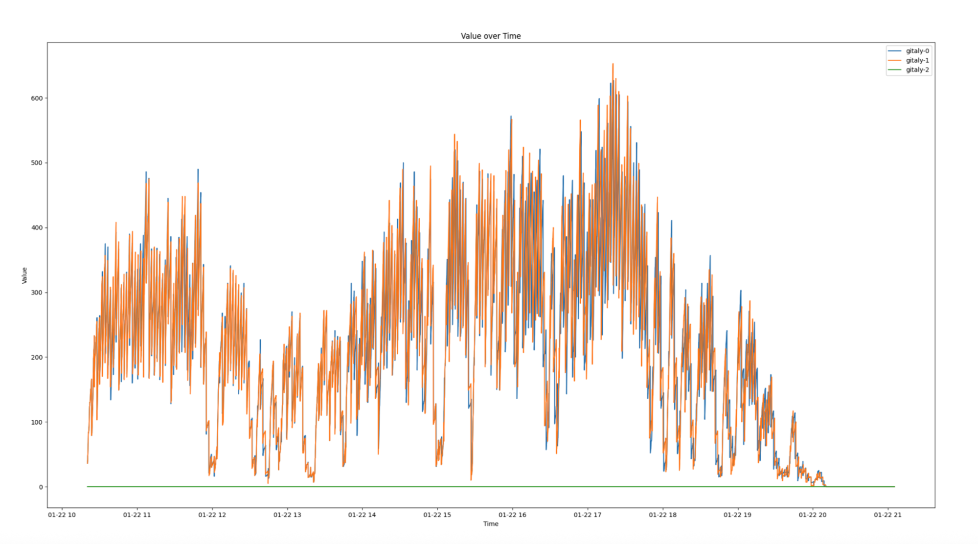
Effortless enterprise authentication at Grab: Dex in action

Post Syndicated from Grab Tech original https://engineering.grab.com/dex-in-action

Introduction

Grab, Southeast Asia’s leading superapp, has created many internal applications to support its diverse range of internal and external business needs. Authentication1 and authorisation2 serve as fundamental components of application development, as robust identity and access management are essential for all systems.

We recognised the need for a centralised internal system to manage access, authentication, and authorisation. This system would streamline access management, ensure compliance with audit requirements, enhance developer velocity, and simplify authentication and authorisation processes for both developers and business operations.

Grab created Concedo to fulfill this requirement by providing a mechanism for services to configure their access control based on their specific role to permission matrix (R2PM)3. This allows for quick and easy integration with Concedo, enabling developers to expedite the shipping of their systems without investing excessive time in building the authentication and authorisation module.

The authentication mechanism, based on Google’s OAuth2.04, includes custom features that enhance identity for service integration. However, this customisation isn’t standard, creating integration challenges with external platforms like Databricks and Datadog. These platforms then use their own authentication and authorisation, resulting in a fragmented and undesirable sign-on experience for users.

Figure 1. Undesired user sign-on experience due to fragmented authentication approaches.

The inconsistency in user experience also resulted in complications. The lack of standardisation led to difficulties in establishing authentication and authorisation for individual applications. Additionally, it created substantial administrative overhead due to the necessity of managing multiple identities. The absence of standardisation also hindered transparency in access control across all applications.

This led us to inquire how a standardised protocol could be established to function seamlessly across all applications, regardless of whether they were developed internally or sourced from external platforms.

Figure 2. Desired state, having something in between the different identity providers (IdP).

Choosing among industry standards

We wanted to build a platform to serve both authentication and authorisation, providing a seamless integration and user sign-on experience. We then asked ourselves, “What are the current industry standards we can leverage on?”.

  • Security Assertion Markup Language (SAML): An authentication protocol which leverages heavily on session cookies to manage each authentication session.
  • Open Authorisation (OAuth): An authorisation protocol which focuses on granting access for particular details rather than providing user identity information.
  • OpenID Connect (OIDC)5: An authentication protocol built on OAuth 2.0, enabling single sign-on (SSO). OIDC unifies and standardises user authentication, making it a solution for organisations with numerous applications.

OIDC enhances user experience by redirecting them to an identity provider (IdP) like Google or Microsoft for authentication when accessing an application. Upon successful verification, the IdP sends a secure token with the user’s identity information back to the application, granting access without the need for additional credentials.

With OIDC, authentication and authorisation are fully implemented, enabling seamless integration across platforms, including mobile, API, and browser-based applications, while also providing SSO functionality.

Figure 3. Desired state with the protocol decided.

OIDC seemed like an ideal solution, but it came with potential drawbacks:

  • OIDC relies on trusting a third-party authentication service. Any disruption to this service could result in downtime.
  • Compromised credentials could affect access to multiple services.

In the following section, we will explore our strategies in mitigating these challenges effectively.

Implementing the chosen standard

With OIDC chosen as the standard, the focus shifted to implementation.

We have always been a supporter of open source projects. Rather than building a platform from the ground up, we leveraged existing solutions while seeking opportunities to contribute back to the open source community.

The team explored Cloud Native Computing Foundation (CNCF) projects and discovered Dex – A federated OpenID connect provider that aims to allow integration of any IdP into an application using OIDC. Dex was selected as our open-source platform of choice due to its alignment with our high-level objectives.

Figure 4. Desired state with Dex as the platform foundation.

How Dex works

Figure 5. High level architecture of Dex. [Source](https://dexidp.io/docs/)

When a user or machine tries to access a protected application or service, they are redirected to Dex for authentication. Dex acts as a middleman (identity aggregator) between the user and various IdPs to establish an authenticated session.

Figure 6. Simplified sequence diagram of how authentication works for Dex.

Dex’s key features include enabling SSO experiences, allowing users to access multiple applications after authenticating through a single provider. Dex also supports multiple IdP use cases and provides standardised OIDC authentication tokens.

Dex implementation separated application authentication concerns, established a single source of truth for identity, enabled new IdP additions, ensured adherence to security best practices, and provided scalability for deployments of all sizes.

How Dex is streamlining authentication and authorisation

Token delegation

When services communicate with each other, one service often assigns an identity to ensure that authorisation can be carried out on a specific service. For example, in figure 7, a service account or robot account is typically used as an identity so that service B can identify the caller.

Figure 7. Service identification through service account.

Although service accounts are the recommended approach for enabling Service B to identify the caller, they come with challenges that must be addressed:

  • Service account compromise: Service accounts often have high-level privileges and typically broad access to Service B. If compromised, they pose a significant security risk, making careful management essential.
  • Access control issue: The other approach creates unnecessary complexity by requiring Service A to handle user-level permissions for Service B. This violates the principle of separation of concerns.

To address this issue, Dex introduced a token exchange feature.

Figure 8. Token exchange example with trusted peers established.

The token exchange process involves two main components; token minting and trust relationship.

Token minting

  1. The user (Alice) logs into Service A.
  2. Service A, acting as a trusted peer, is authorised to mint tokens.
  3. Service A generates a token valid for both Service A and Service B. This is reflected in the token’s “aud” (audience) field: “aud”: “serviceA serviceB”

Trust relationship

  • Service B must be configured to trust Service A as a peer.
  • Service B accepts tokens minted by Service A.

This approach differs from the service account-based scenario by using a trust-based peer relationship. Service A is authorised to mint tokens for Service B providing a more sophisticated but preferred method. The token is properly scoped for both services, ensuring a clear audit trail of token issuance, while reducing token manipulation risks.

Kill switch

As highlighted earlier,

OIDC relies on trusting a third-party authentication service. Any disruption to this service could result in downtime.

Dex’s ability to support multiple IdPs enables traffic to be shifted to a different IdP if one, such as Google, experiences an outage. This “kill switch” mechanism ensures that integrated services are not disrupted and do not require any changes to mitigate the issue. It is only triggered during specific IdP outages.

Figure 9. Trigger kill switch without having other services changing from their end.

Looking forward

Following the successful implementation of Dex as the unified authentication provider, the next phase in enhancing our identity and access management infrastructure is to leverage this robust identity foundation to establish a unified and simplified authorisation model. This initiative is driven by the recognition that the current authorisation landscape remains fragmented and complex, leading to potential inefficiencies and security vulnerabilities.

By centralising authorisation and aligning it with the unified identity provided by Dex, we can streamline access control, improve user experience, and strengthen security across our applications and services. This will involve consolidating authorisation policies, standardising access control mechanisms, and simplifying the management of user permissions.

Shoutout to the awesome Concedo team for driving Dex integration and to our leadership for steering the way toward a simpler, unified authentication and authorisation journey!

Join us

Grab is a leading superapp in Southeast Asia, operating across the deliveries, mobility and digital financial services sectors. Serving over 800 cities in eight Southeast Asian countries, Grab enables millions of people everyday to order food or groceries, send packages, hail a ride or taxi, pay for online purchases or access services such as lending and insurance, all through a single app. Grab was founded in 2012 with the mission to drive Southeast Asia forward by creating economic empowerment for everyone. Grab strives to serve a triple bottom line – we aim to simultaneously deliver financial performance for our shareholders and have a positive social impact, which includes economic empowerment for millions of people in the region, while mitigating our environmental footprint.

Powered by technology and driven by heart, our mission is to drive Southeast Asia forward by creating economic empowerment for everyone. If this mission speaks to you, join our team today!
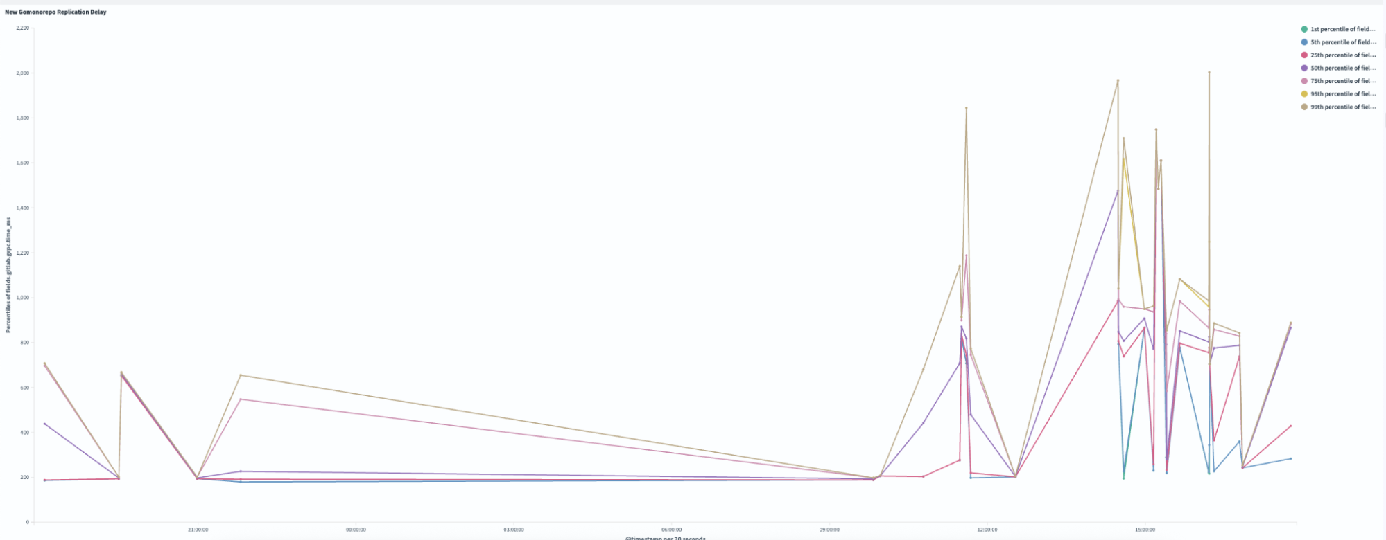
Definition of terms

  1. Authentication: Who you are. Making sure you are who you say you are by verifying your identity. ↩

  2. Authorisation: What you can do. Defining the resources or actions you are allowed to access or perform after your identity has been verified. ↩

  3. Role-to-Permission Matrix (R2PM): A structured framework used to map roles within an organisation to the permissions or access rights each role has in a system, application, or process. This matrix serves as a critical component in access control and identity management, ensuring that users have appropriate access based on their roles while minimising the risk of unauthorised access. ↩

  4. Open Authorisation (OAuth 2.0): Protocol for authorisation. For example, Google Login on third-party portals allows your identity to remain with Google, but third-party portals can obtain limited access to specific data such as your profile photo. ↩

  5. OpenID Connect (OIDC): Identity protocol built on top of OAuth 2.0. On top of authorisation provided by OAuth 2.0, it verifies and provides a trusted identity. ↩

From failure to success: The birth of GrabGPT, Grab’s internal ChatGPT

Post Syndicated from Grab Tech original https://engineering.grab.com/the-birth-of-grab-gpt

Introduction

In March 2023, I embarked on a mission to explore the potential of Large Language Models (LLMs) within Grab. What started off as an attempt to solve a specific problem—reducing the burden on our ML Platform team’s support channels, ended up becoming something much bigger. The creation of GrabGPT, an internal ChatGPT-like tool that has transformed how folks in Grab interact with AI. This is the story of how a failed experiment led to one of Grab’s most impactful internal tools.

The problem: Overwhelmed support channels

As part of Grab’s machine learning platform team, we were drowning in user inquiries. Slack channels were flooded with questions and our on-call engineers were spending more time answering repetitive queries than building innovative solutions. This led me to ponder on this question, “could we use LLMs to build a chatbot that understands our platform’s documentation and answers these questions automatically?”

The first attempt: A chatbot for platform support

I started by exploring open-source frameworks to build a chatbot. I stumbled upon chatbot-ui, a simple yet powerful tool that could be wired up with LLMs. My idea was to feed the chatbot our platform’s Q\&A documentation (over 20,000 words) and let it handle user queries.

But there was a catch: GPT-3.5-turbo could only handle 8,000 tokens (~2,000 words). I spent days summarising the documentation, reducing it to less than 800 words. While the chatbot worked for a handful of frequently asked questions, it was clear that this approach wasn’t scalable. I tried with embedding search and it didn’t work that well too, so I decided to give up on this idea.

The pivot: Why not build Grab’s own ChatGPT?

As I stepped back, a new thought struck me: Grab doesn’t have its own ChatGPT-like tool yet. I had the frameworks, the LLM knowledge, and most importantly—access to Grab’s model-serving platform, catwalk. Why not build an internal tool that any Grabber could use?

Over a weekend, I extended the existing frameworks, added Google login for authentication, and deployed the tool internally. I called it Grab’s ChatGPT. Little did I know, this would become one of the most widely used tools in the company.

The tool quickly became a staple for Grabbers, especially in regions where ChatGPT was inaccessible (e.g., China). The name evolved too—our PM suggested GrabGPT, and it stuck.

The Success: GrabGPT takes off

The response was overwhelming:

  • Day 1: 300 users registered.
  • Day 2: 600 new users.
  • Week 1: 900 new users
  • Month 3: Over 3000 users, with 600 daily active users
  • Today: Almost all Grabbers are using GrabGPT.
Figure 1: Number of GrabGPT users in one month

Why GrabGPT works: More than just technology

The success of GrabGPT isn’t just about the tech,it’s about timing, security, and accessibility. Here’s why it resonated so deeply within Grab:

  1. Data security: GrabGPT operates on a private route, ensuring that sensitive company data never leaves our infrastructure.
  2. Global accessibility: Unlike ChatGPT, which is banned in some regions, GrabGPT is accessible to all Grabbers, regardless of location.
  3. Model agnosticism: GrabGPT isn’t tied to a single LLM provider. It supports models from OpenAI, Claude, Gemini, and more.
  4. Auditability: Every interaction on GrabGPT is auditable, making it a favorite of our data security and governance teams.

The broader impact: A catalyst for LLM strategy

GrabGPT didn’t just solve an immediate problem, it sparked a broader conversation about how LLMs can be leveraged across Grab. It showed that a single engineer, provided with the right tools and timing, can create something transformative. Today, GrabGPT is more than a tool; it’s a testament to the power of experimentation and adaptability.

Lessons learned

  1. Failure is a stepping stone: My initial failure with the support chatbot which then led me to a much bigger opportunity.
  2. Timing matters: GrabGPT succeeded because it addressed a critical need at the right time.
  3. Think big, start small: What began as a weekend project became a company-wide tool.
  4. Collaboration is key: The enthusiasm and contributions from other Grabbers were instrumental in scaling GrabGPT.

Conclusion

GrabGPT is a story of resilience, innovation, and the unexpected rewards from thinking outside the box. It’s a reminder that sometimes, the best solution comes from pivoting away from what doesn’t work and embracing new possibilities. As LLMs continue to evolve, I’m excited to see how GrabGPT will grow and inspire even more innovation within Grab.

I would like to end this article by letting readers know that if you’re working on a project and feel stuck, don’t be afraid to pivot. You never know, your next failure might just be the beginning of your greatest success. And if you’re at Grab, give GrabGPT a try. It might just change the way you work!

Join us

Grab is a leading superapp in Southeast Asia, operating across the deliveries, mobility and digital financial services sectors. Serving over 800 cities in eight Southeast Asian countries, Grab enables millions of people everyday to order food or groceries, send packages, hail a ride or taxi, pay for online purchases or access services such as lending and insurance, all through a single app. Grab was founded in 2012 with the mission to drive Southeast Asia forward by creating economic empowerment for everyone. Grab strives to serve a triple bottom line – we aim to simultaneously deliver financial performance for our shareholders and have a positive social impact, which includes economic empowerment for millions of people in the region, while mitigating our environmental footprint.

Powered by technology and driven by heart, our mission is to drive Southeast Asia forward by creating economic empowerment for everyone. If this mission speaks to you, join our team today!
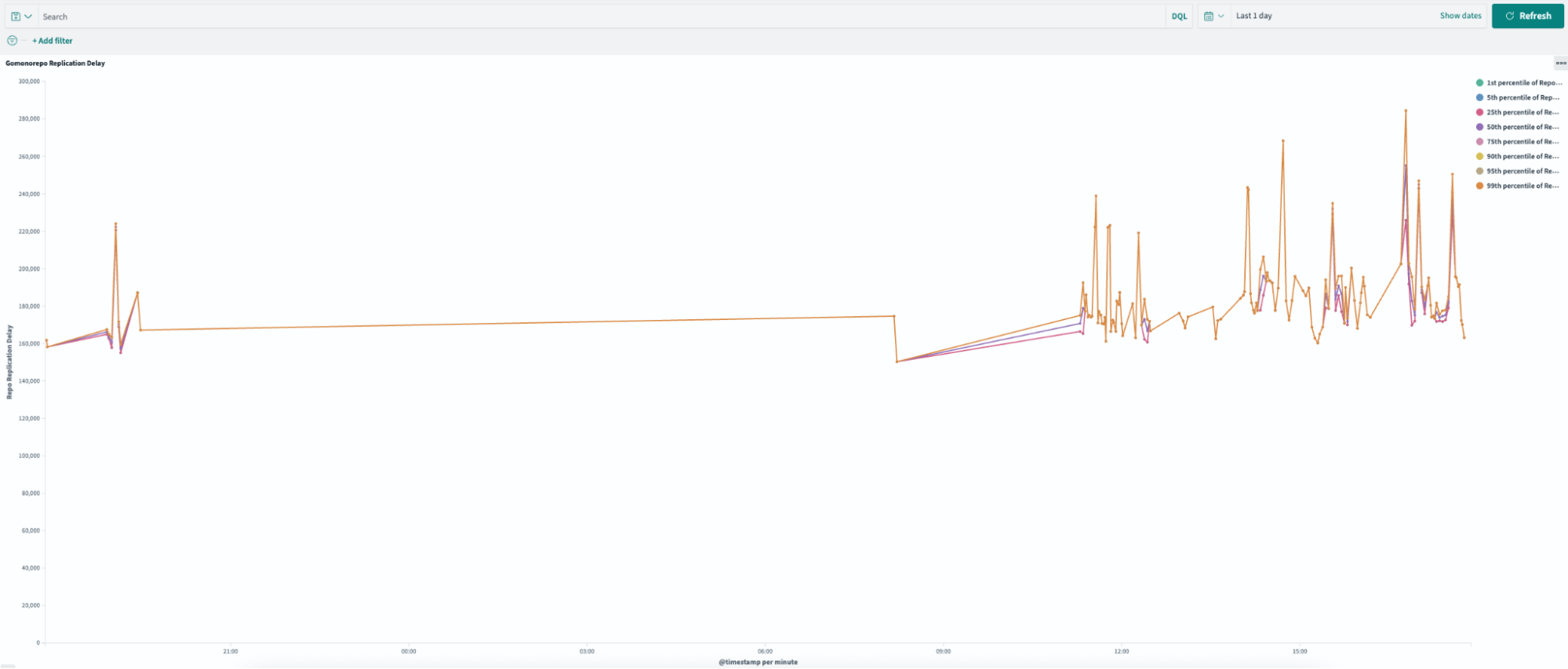
Streamlining RiskOps with the SOP agent framework

Post Syndicated from Grab Tech original https://engineering.grab.com/streamlining-riskops-with-sop

Introduction

In the blog our previous introduction to the SOP-driven LLM Agent Framework, we the potential of LLM agent framework to revolutionise business operations was discussed. Now, we’re excited to explore a compelling use case: automating Account Takeover (ATO) investigations in Risk Operations (RiskOps). This framework has significantly reduced manual effort, improved efficiency, and minimised errors in the investigation process, setting a new standard for secure and streamlined operations.

The challenge in RiskOps

Traditionally, ATO investigations have been fraught with challenges due to their complexity and the manual effort required. Analysts must sift through vast amounts of data, cross-referencing multiple systems and executing numerous SQL queries to make informed decisions. This process is not only labor-intensive but also susceptible to human error, which can lead to inconsistencies and potential security breaches.

The manual approach often involves:

  • Time-consuming data analysis: Analysts spend significant time gathering and interpreting data from disparate sources, leading to delays and inefficiencies.
  • Decision fatigue: Continuous decision-making in a high-pressure environment can result in oversight or errors, especially when relying on predefined thresholds without adaptive insights.
  • Resource constraints: The need for specialised skills to handle SQL queries and interpret complex patterns limits the scalability of the process.

These challenges highlight the need for a more efficient, reliable, and scalable solution.

Leveraging the SOP agent framework

Our framework transforms the ATO investigation process by mirroring manual workflows while leveraging advanced automation.

At its core, a Standard Operating Procedure (SOP) guides the investigation process. This comprehensive SOP, is designed with an intuitive tree structure. It outlines the sequence of investigative actions, required data for each step, necessary SQL queries and external function calls, as well as decision criteria guiding the investigation. Figure 1 shows the example of ATO investigation SOP.

Figure 1: Example of fictional ATO investigation SOP

The SOP is written in natural language in an indentation format. Users can easily define SOPs using an intuitive editor. This format also clearly denotes the specific functions or queries associated with each step in the SOP. The @function_name notation (eg. @IP_web_login_history) makes it easy to identify where external calls are made within the process, highlighting the integration points between the SOP-driven LLM agent framework and the existing systems or databases.

Dynamic execution

The dynamic execution engine consists of the SOP planner and the Worker Agent, working in tandem to drive efficient operations. The SOP planner serves as the navigator, guiding the investigation’s path by generating the necessary SOP steps and determining the appropriate APIs to call. It uses a structured execution approach inspired by Depth-First Search (DFS) to ensure thorough and systematic processing. Meanwhile, the Worker Agent acts as the executor, interpreting the JSON-formatted SOPs, invoking required APIs or SQL queries, and storing results. This continuous interplay between the SOP planner and the Worker Agent establishes an efficient feedback loop, propelling the investigation forward with precision and reliability.

The automated investigation process begins at the root of the SOP tree and methodically progresses through each defined step. At each juncture, the system executes specified SQL queries as needed, retrieving and analysing relevant data. Based on this analysis, the framework evaluates step specific criteria and makes informed decisions that guide subsequent steps. This iterative process allows the investigation to delve as deeply into the data as the SOP dictates, ensuring both thoroughness and efficiency.

As the investigation concludes, having completed all of the steps, the framework enters its final phase. It compiles a comprehensive summary of the entire process, synthesising all gathered information to generate a final decision. The culmination of this process is a detailed report that encapsulates the investigation’s findings and provides clear, actionable conclusions.

This automated approach combines the best of human expertise with computational efficiency. It maintains the depth and detail of a human-conducted investigation while leveraging the speed and consistency of automation. The result is a powerful tool that can handle complex investigations with precision and reliability, making it an invaluable asset in various fields requiring thorough and systematic analysis.

Figure 2: Example of dynamic execution

Efficiency, impact and future potential

The SOP-driven LLM agent framework has demonstrated remarkable efficiency and impact in automating RiskOps processes. By automating data handling and leveraging AI to adapt to emerging patterns, the framework has significantly reduced manual tasks and streamlined operations. Figure 3 shows an example of an automated RiskOps process integrated with Slack.

Figure 3: Slack integration

Key achievements of automating RiskOps process:

  • Reduction in handling time from 22 to 3 minutes per ticket.
  • Automation of 87% of ATO cases since launch.
  • Achievement of a zero-error rate, enhancing both efficiency and security.

These results not only demonstrate the framework’s effectiveness in streamlining RiskOps but also provide stakeholders with increased confidence in the security and reliability of their operations.

The success of the framework in automating ATO investigations opens the door to a wider range of applications across various sectors. By adapting the framework to different processes, organisations can achieve similar improvements in efficiency and reliability, leading to a more responsive and agile business environment.

Conclusion

The SOP-driven LLM agent framework is more than an automation tool. It’s a catalyst for transforming enterprise operations. By applying it to ATO investigations, we’ve demonstrated its potential to enhance efficiency, reliability, and security. As we continue to explore its capabilities, we anticipate unlocking new levels of productivity and innovation across industries.

We look forward to sharing more as we explore how this groundbreaking framework can be applied to various challenges, helping organisations navigate the complexities of modern operations with confidence and precision.

Join us

Grab is a leading superapp in Southeast Asia, operating across the deliveries, mobility and digital financial services sectors. Serving over 800 cities in eight Southeast Asian countries, Grab enables millions of people everyday to order food or groceries, send packages, hail a ride or taxi, pay for online purchases or access services such as lending and insurance, all through a single app. Grab was founded in 2012 with the mission to drive Southeast Asia forward by creating economic empowerment for everyone. Grab strives to serve a triple bottom line – we aim to simultaneously deliver financial performance for our shareholders and have a positive social impact, which includes economic empowerment for millions of people in the region, while mitigating our environmental footprint.

Powered by technology and driven by heart, our mission is to drive Southeast Asia forward by creating economic empowerment for everyone. If this mission speaks to you, join our team today!
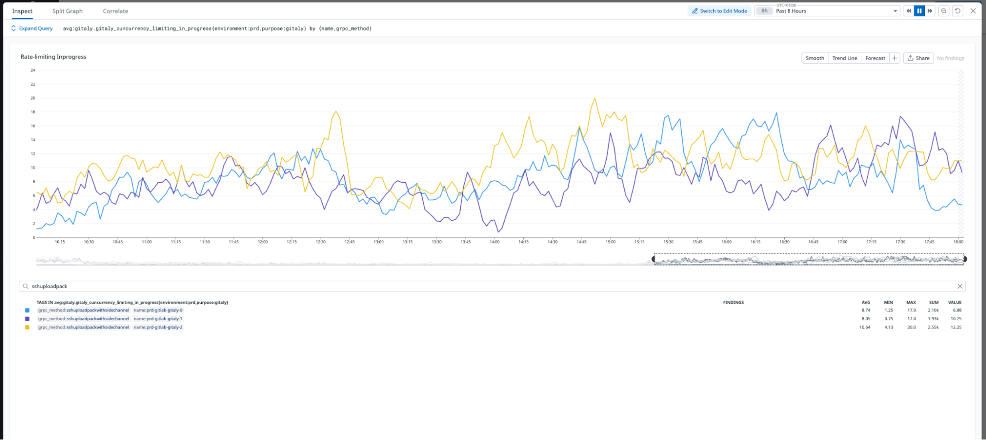
Introducing the SOP-driven LLM agent frameworks

Post Syndicated from Grab Tech original https://engineering.grab.com/introducing-the-sop-drive-llm-agent-framework

Introduction

We’re excited to introduce an innovative Large Language Model (LLM) agent framework that reimagines how enterprises can harness the power of AI to streamline operations and boost productivity. At its core, this framework leverages Standard Operating Procedures (SOPs) to guide AI-driven execution, ensuring reliability and consistency in complex processes. Initial evaluations have shown remarkable results, with over 99.8% accuracy in real-world use cases. For example, the framework has powered solutions like the Account Takeover Investigations (ATI) bot, which achieved a 0 false rate while reducing investigation time from 23 minutes to just 3, automating 87% of cases. The fraud investigation use case also reduced the average handling time (AHT) by 45%, saving over 300 man-hours monthly with a 0 false rate, demonstrating its potential to transform even the most intricate enterprise operations with a high degree of accuracy.

The framework’s capabilities extend far beyond just accuracy, it offers a versatile suite of tools that revolutionise automation and app development, enabling AI-powered solutions up to 10 times faster than traditional methods.

The power of SOPs in AI automation

Traditional agent-based applications often use LLMs as the core controller to navigate through standard operating procedure (SOPs). However, this approach faces several challenges. LLMs may make incorrect decisions or invent non-existent steps due to hallucination. As generative models, they struggle to consistently produce results in a fixed format. Moreover, navigating complex SOPs with multiple branching pathways is particularly challenging for LLMs. These issues can lead to inefficiencies and inaccuracies in implementing business operations, especially when dealing with intricate, multi-step procedures.

Our framework addresses these challenges head-on by leveraging the structure and reliability of SOPs. We represent SOPs as a tree, with nodes encapsulating individual actions or decision points. This structure supports both sequential and conditional branching operations, mirroring the hierarchical nature of real-world business processes.

To make this powerful tool accessible to all, we’ve developed an intuitive SOP editor that allows non-technical users to easily define and visualise complex workflows. These visual representations are then converted into a structured, indented format that our system can interpret and execute efficiently.

Figure 1: SOP editor in our framework

The example above demonstrates how our framework transforms the customer support process by mirroring manual workflows while leveraging advanced automation. The SOP is written in natural language using an indentation format, making it easy for users to define and understand. The @function_name (@get_order_detail) notation clearly identifies where external calls are made within the process, highlighting the integration points between the SOP-driven LLM agent framework and existing systems or databases.

The magic behind the scenes

The framework’s strength lies in the synergy between three key components: the planner module, LLM-powered worker agent, and user agent. This intelligent trio works in harmony to deliver a seamless, efficient, and adaptable automation experience.

The planner module employs a Depth-First Search (DFS) algorithm to navigate the SOP tree, ensuring thorough execution with step-by-step prompt generation and sophisticated backtracking mechanisms. The LLM-powered worker agent dynamically updates its understanding and makes decisions based on the most current information. Our approach tackles hallucination and improves efficiency through context compression and strategic limitation of available Application Programming Interface tools (APIs). The framework’s dynamic branching capability allows for adaptive navigation based on real-time data and analysis.

Serving as the primary user interface, the user agent offers multilingual interaction, accurate intent identification, and seamless handling of out-of-order scenarios.

By combining structured SOPs with flexible LLM-powered agents and advanced algorithmic approaches, our framework adeptly handles complex, real-world scenarios while maintaining reliability and consistency. This innovative architecture effectively mitigates common LLM challenges, resulting in a robust system capable of navigating intricate business processes with high accuracy and adaptability.

Beyond SOPs: A suite of powerful features

While SOPs form the backbone of our framework, we’ve incorporated several other cutting-edge features to create a truly comprehensive solution. Our Graph Retrieval-Augmented Generation (GRAG) pipeline enhances information retrieval and content generation tasks, allowing for more accurate and context-aware responses. The workflow feature enables chaining multiple plugins together to handle complex processes effortlessly, improving efficiency across various departments.

Our plugin system seamlessly integrates with various technologies such as API, Python, and SQL, providing the flexibility to meet diverse needs. Whether you’re an engineer coding in Python, a data analyst working with SQL, or a risk operations specialist, our plugin system adapts to your preferred tools. Additionally, our playground feature allows users to develop, test, and refine LLM applications easily in an interactive environment, supporting the latest multi-modal APIs for accelerated innovation.

Figure 2: Workflow builder feature in our framework

Empowering teams through versatility and accessibility

Our framework is designed to empower teams across the organisation. The multilingual capabilities of our user agent ensure that language barriers don’t hinder adoption or efficiency. For scenarios requiring human intervention, we’ve implemented a state stack that allows for pausing and resuming execution seamlessly. This feature ensures that complex processes can be handled with the right balance of automation and human oversight.

Security and transparency at the forefront

In an era where data security and process transparency are paramount, our framework doesn’t fall short. It’s designed with a security-first approach, ensuring granular access control so that users only access information they’re authorised to see. Additionally, we provide detailed logging and visualisation of each execution, offering complete explainability of the automation process. This level of transparency not only aids in troubleshooting but also helps in building trust in the AI-driven processes across the organisation.

Looking ahead

As we continue to refine and expand this LLM agent framework, we’re excited to explore its potential across different industries. We’ll be sharing more about each of these features in the future and showcase how they can be leveraged to solve specific business challenges and explore real-world applications.

Look forward to more in-depth explorations of the framework’s capabilities, use cases, and technical innovations. With this revolutionary approach, you’re not just automating tasks – you’re transforming the way your enterprise operates, unleashing the true power of LLM in your organisation.

Join us

Grab is a leading superapp in Southeast Asia, operating across the deliveries, mobility and digital financial services sectors. Serving over 800 cities in eight Southeast Asian countries, Grab enables millions of people everyday to order food or groceries, send packages, hail a ride or taxi, pay for online purchases or access services such as lending and insurance, all through a single app. Grab was founded in 2012 with the mission to drive Southeast Asia forward by creating economic empowerment for everyone. Grab strives to serve a triple bottom line – we aim to simultaneously deliver financial performance for our shareholders and have a positive social impact, which includes economic empowerment for millions of people in the region, while mitigating our environmental footprint.

Powered by technology and driven by heart, our mission is to drive Southeast Asia forward by creating economic empowerment for everyone. If this mission speaks to you, join our team today!
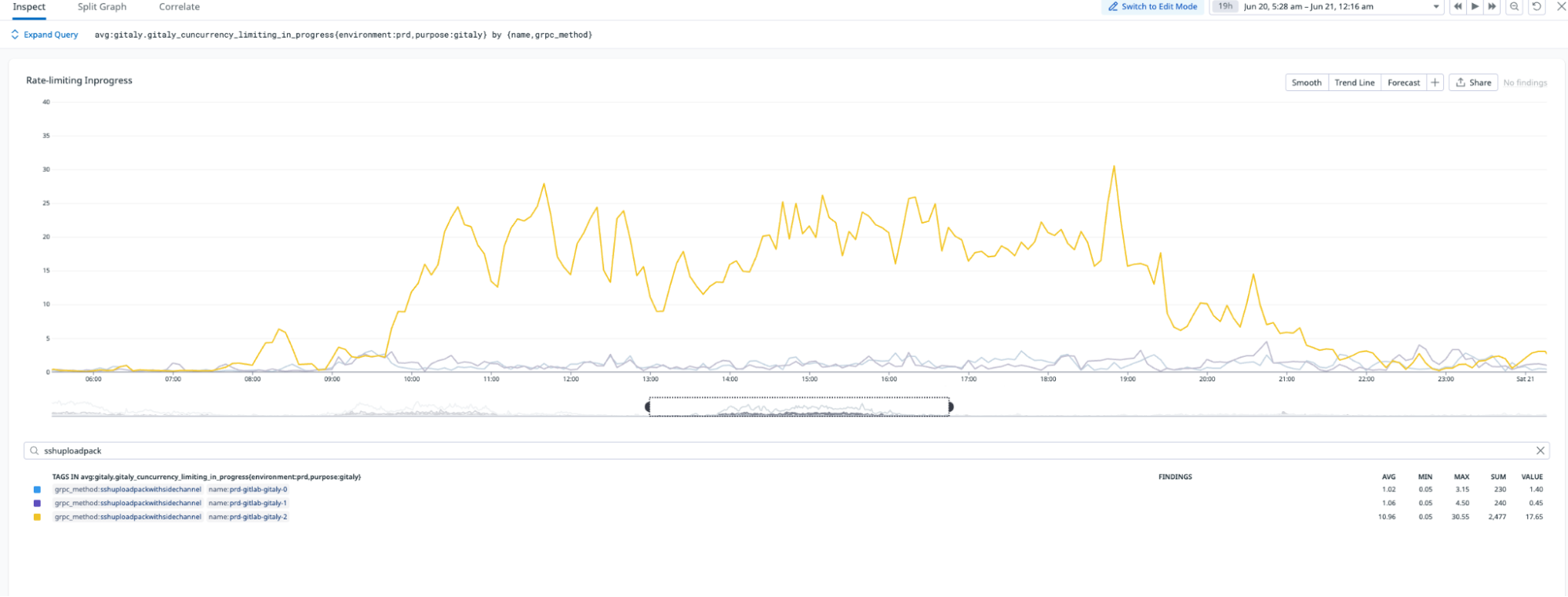
Evaluating performance impact of removing Redis-cache from a Scylla-backed service

Post Syndicated from Grab Tech original https://engineering.grab.com/evaluate-performance-remove-redis-from-scylla-service

Introduction

At Grab, we operate a set of services that manage and provide counts of various items. While this may seem straightforward, the scale at which this feature operates—benefiting millions of Grab users daily—introduces complexity. This feature is divided into three microservices: one for “writing” counts, another for handling “read” requests, and a third serving as the backend for a portal used by data scientists and analysts to configure these counters.

This article focuses on the service responsible for handling “read” requests. This service is backed by Scylla storage and a Redis cache. It also connects to a MySQL RDS to retrieve “counter configurations” that are necessary for processing incoming requests. Written in Rust, the service serves tens of thousands of queries per second (QPS) during peak times, with each request typically being a “batch request” requiring multiple lookups (~10) on Scylla.

Recently, the service has encountered performance challenges, causing periodic spikes in Scylla QPS. These spikes occur throughout the day but are particularly evident during peak hours. To understand this better, we’ll first walk you through how this service operates, particularly how it serves incoming requests. We will then explain our proposed solution and the outcomes of our experiment.

Anatomy of a request

Each counter configuration stored in MySQL has a template that dictates the format of incoming queries. For example, this sample counter configuration is used to count the raindrops for a specific city:

{
    "id": 34,
    "name": "count_rain_drops",
    "template": "rain_drops:city:{city_id}"
    ....
    ....
}

An incoming request using this counter might look like this:

{
    "key": "rain_drops:city:111222",
    "fromTime": 1727215430, // 24 September 2024 22:03:50
    "toTime": 1727400000, // 27 September 2024 01:20:00
}

This request seeks the number of raindrops in our imaginary city with city ID: 111222, between 1727215430 (24 September 2024 22:03:50) and 1727400000 (27 September 2024 01:20:00).

Another service keeps track of raindrops by city and writes the minutely (truncated at 15 minutes), hourly, and daily counts to three different Scylla tables:

  • minutely_count_table
  • hourly_count_table
  • daily_count_table

The service processing the request rounds down the time to the nearest 15 minutes. As a result, the request is processed with the following time range:

  • Start time: 24 September 2024 22:00:00
  • End time: 27 September 2024 01:15:00

Let’s assume we have the following data in these three tables for “rain_drops:city:111222”. The datapoints used in the above example request are highlighted in bold.

minutely_count_table:

key minutely_timestamp count
rain_drops:city:111222 2024-09-24T22:00:00Z 3
rain_drops:city:111222 2024-09-24T22:15:00Z 2
rain_drops:city:111222 2024-09-24T22:30:00Z 4
rain_drops:city:111222 2024-09-24T22:45:00Z 1
… … …
rain_drops:city:111222 2024-09-27T01:00:00Z 2
rain_drops:city:111222 2024-09-27T01:15:00Z 3

hourly_count_table:

key hourly_timestamp count
rain_drops:city:111222 2024-09-24T22:00:00Z 18
rain_drops:city:111222 2024-09-24T23:00:00Z 22
rain_drops:city:111222 2024-09-25T00:00:00Z 15
… … …
rain_drops:city:111222 2024-09-27T00:00:00Z 11
rain_drops:city:111222 2024-09-27T01:00:00Z 9

daily_count_table:

key daily_timestamp count
rain_drops:city:111222 2024-09-24T00:00:00Z 214
rain_drops:city:111222 2024-09-25T00:00:00Z 189
rain_drops:city:111222 2024-09-26T00:00:00Z 245
rain_drops:city:111222 2024-09-27T00:00:00Z 78

Now, let’s see how the service calculates the total count for the incoming request with “rain_drops:city:111222” based on the provided data:

Time range:

  • From: 24 September 2024 22:03:50
  • To: 27 September 2024 01:20:00

For the full days within the range, specifically 25th and 26th September, we can use data from the daily_count_table. However, for the start (24th September) and end (27th September) date of the range, we cannot use data from the daily_count_table as the range only includes portions of these dates. Instead, we will use a combination of data from the hourly_count_table and minutely_count_table to accurately capture the counts for these days.

  1. Query the daily_count_table:

    Sum (full day: 25 and 26th Sep): 189 + 245 = 434

  2. Query the hourly_count_table:
    • For 24th September (from 22:00:00 to 23:59:59):

      Hourly count: 18 + 22 = 40

    • For 27th September (from 00:00:00 to 01:00:00):

      Hourly count: 11

  3. Query the minutely_count_table:

    For 27th September (from 01:00:00 to 01:15:00):

    Minutely count: 2

  4. Total count:

    Total = Daily count (25th and 26th) + Hourly count (24th) + Hourly count (27th) + Minutely count (27th)

    = 434 + 40 + 11 + 2

    = 487

Figure 1: The example request for “rain_drops:city:111222” is handled using data from three different Scylla tables.

As shown in the calculation, when the service receives the request, it comes up with the total count of raindrops by querying three Scylla tables and summing them up using some specific rules within the service itself.

Querying the cache

In the previous section, we explained how Scylla handles a query. If we cached the response for the same request earlier, retrieval from the cache follows a simpler logic. For instance, for the example request, the total count is stored using the floored start and end times (rounded to the nearest 15-minute window within an hour), which was used for the Scylla query instead of the original time in the request. The cache key-value pair would look like this:

  • key: id:34:rain_drops:city:111222:1727215200:1727399700
  • value: 487

Timestamps 1727215200 and 1727399700 represent the adjusted start and end times of 24 September 2024 22:00:00 and 27 September 2024 01:15:00, respectively. It has a Time-To-Live (TTL) of 5 minutes. During this TTL window, any request for the key “rain_drops:city:111222” having the same start and end times (after rounding to the nearest 15 minutes) will be read from the cache instead of querying Scylla.

For example, for the following three start times, although they are different, after flooring the request to the nearest 15 minutes, the start time becomes 24 September 2024 22:00:00 for all of them, which is the same start time as the one in the cache.

  • 24 September 2024 22:01:00
  • 24 September 2024 22:02:00
  • 24 September 2024 22:06:00

In day-to-day operations, this caching setup allows roughly half of our total production requests to be served by the Redis cache.

Figure 2. The graph visualises the relative quantity of cache hits vs Scylla-bound requests.

Problem statement

The setup consisting of Scylla and Redis cache works well. Particularly because Scylla-bound queries need to look up 1-3 tables (minutely, hourly, daily, depending on the time range) and perform the summation as explained earlier, whereas a single cache lookup gets the final value for the same query. However, as our cache key pattern follows the 15-minute truncation strategy, along with a 5-minute cache TTL, it leads to an interesting phenomenon – our cache hits plummet and Scylla QPS spikes at the end of every 15 minutes.

Figure 3. Graph showing 15-minute spikes in Scylla-bound requests accompanied by a decline in cache hit rates.

This occurs primarily due to the fact that almost all requests to our service are for recent data. Due to this, at the end of every 15-minute block within an hour (i.e., 00, 15, 30, 45), most of the requests require creating new cache keys for the latest 15-minute block. At this point in time, there may be many unexpired (i.e., have not reached 5 min TTL) cache keys from the previous 15-minutes block, but they become less relevant as most requests are asking for recent data.

The table in Figure 4 shows example data for configurations “rain_drops:city:111222” and “bird_sighting:city:333444”. For these two configurations, new cache keys are created due to TTL expiry at random times. However, at the end of the 15-minute block, which, in this case is at the end of 22:00-22:15 block, both configurations need new cache keys for the new 15-minute time block that has just started (i.e., start of 22:15-22:30), even though some of their cache keys from the previous 15-minute block are still valid. This requirement of creating new cache keys for most of the requests at the end of a 15-minute block causes spikes in Scylla QPS and a sharp decline in cache hits.

One question that arises is – “Why don’t we see a spike every 5 minutes for cache key TTL expiry?” This is because, within the 15 minutes block, new cache keys are continuously created when a key reaches TTL and a new request for that is received. Since this happens all the time as shown in Figure 4, we do not see a sharp spike. In other words, although Scylla does receive more queries due to cache TTL expiry, it does not lead to a spike in Scylla queries or a sharp drop in cache hits. This is because the cache keys are always being created and invalidated due to TTL expiry instead of following a fixed 5-minute block similar to the 15-minute block we use for our truncation strategy.

Figure 4. This table visualises scenarios when new cache keys are required due to TTL expiry vs due to 15-minute truncation strategy.

These Scylla QPS spikes at the end of every 15-minute block lead to a highly imbalanced Scylla QPS. This often causes high latency in our service during the 15-minute blocks that fall within the peak traffic hours. This further causes more requests to time out, eventually increasing the number of failed requests.

Proposed solution

We propose mitigating this issue by completely removing the Redis-backed caching mechanism from the service. Our observations indicate that the Scylla spikes at the end of 15-minute blocks occur due to cache hit misses. Therefore, removing the caching should eliminate the spikes and provide for a more balanced load.

We acknowledge that this may seem counterintuitive from an overall performance standpoint as removing caching means all queries will be Scylla-bound, potentially impacting the overall performance since caching usually speeds up processes. In addition, caching also comes with an advantage where for cache hits, the service does not need to do the summation on Scylla results from minutely, hourly, and the daily table. Despite these shortcomings, we hypothesise that removing caching should not have an adverse impact on the overall performance. This is based on the fact the Scylla has its own sophisticated caching mechanism. However, our existing setup uses Redis for caching, underutilising Scylla’s cache as the most subsequent queries hit the Redis cache instead.

In summary, we propose eliminating the Redis caching component from our current architecture. This change is expected to resolve the Scylla query spikes observed at the end of every 15-minute block. By relying on Scylla’s native caching mechanism, we anticipate maintaining the service’s overall performance more effectively. The removal of Redis is counterbalanced by the optimised utilisation of Scylla’s built-in caching capabilities.

Experiment

Procedure

The experiment was done on an important live service serving thousands of QPS. To avoid disruptions, we followed a gradual approach. We first turned off caching for a few configurations. If there were no adverse impacts observed, we incrementally disabled cache for more configurations. We controlled the rollout increment by using a mathematical operator on the configuration IDs. This approach is simple and allows us to deterministically disable the cache for specific configurations across all requests, as opposed to using a percentage rollout which randomly disables the cache for different configurations across different requests. This is also due to the fact that the number of configurations is relatively steady and small (less than a thousand). Since these configurations are already fully cached in the service memory from RDS, there will be no performance impact of having a condition that operates on these configurations.

To make sense of the graphs and metrics reported in this section, it is important to understand the traffic pattern of this service. The service usually sees two peaks every day: noon and another around 6-7 PM. On a weekly basis, we usually see the highest traffic on Friday, with the busiest period being from 6-8 PM.

In addition, the timeline of when and how we made various changes to our setup is important to accurately interpret our results.

Experiment timeline: Nov 5 – Nov 13, 2024:

  • Redis cache disabled for ~5% of the counter configurations – Nov 5, 2024, 10.26 AM (Canary started: 10.00 AM)

  • Redis cache disabled for ~25% of the counter configurations – Nov 5, 2024, 12.44 PM (Canary started: 12.20 PM)

  • Redis cache disabled for ~35% of the counter configurations – Nov 6, 2024, 10.50 AM (Canary started: 10.21 AM)

  • Redis cache disabled for ~75% of the counter configurations – Nov 7, 2024, 10.53 AM (Canary started: 10.26 AM) 

  • Experimenting with running a major compaction job during the day time: Tue, Nov 12, 2024, between 2-5 PM (on all nodes)

  • Day time scheduled major compaction job starts from: Tue, Nov 13, 2024, between 2-5 PM (on all nodes)

  • Redis cache disabled for 100% of the counter configs – Wed, 13 Nov 2024, 10:56 AM (Canary started: 10:32 AM)

Unless otherwise specified, the graphs and metrics we report in this article uses this fixed time window: Oct 31 (Thu) 12.00 AM – Nov 15 (Friday) 11.59 PM SGT. This time window covers the entire experiment period with some buffer to observe the experiment’s impact.

Observations

As we progressively disabled read from external Redis cache over the span of 8 days (Nov 5 – Nov 13), we made interesting observations and experimented with some Scylla configuration changes on our end. We describe them in the following sections.

Scylla hit vs. cache hit

As we progressively disabled Redis cache for most of the counters, one obvious impact was the gradual increase in Scylla-bound QPS and similar decrease in Redis-cache hit. When Redis-cache was enabled for 100% of the configurations, 50% of the requests were bound for Scylla and the other 50% were for Redis. At the end of the experiment, after fully disabling Redis cache, 100% of the requests were Scylla-bound.

Figure 5. Gradual increase in Scylla QPS and simultaneous decrease in Redis cache hit.

15-minutes and hourly spikes

We noticed that the 15-minute spikes in Scylla QPS as well as the associated latency slowly became less prominent and eventually disappeared from the graph after we completely disabled the Redis cache. However, we noticed that the hourly spike still remained. This is attributed to the higher QPS from the clients calling this service at the turn of every hour. As a result, limited optimisation can be done to reduce the hourly spike on this service’s end.

Figure 6. The 15-minute spikes in Scylla QPS disappeared after the external Redis cache was fully disabled. This graph uses a smaller time window to show the earlier spikes. It also shows the persistence of hourly spikes after the experiment which is attributed to the clients of this service sending more requests at the start of every hour.
Figure 7. The graph shows that the 15-minute spikes in Scylla’s latency disappeared after the external Redis cache was fully disabled. This graph uses a smaller time window to show the earlier spikes. It also shows the persistence of hourly spikes in latency after the experiment which is attributed to the clients of this service sending more requests at the start of every hour.

Service latency and additional Scylla compaction job

When we disabled Redis cache for about 75% of the counters configurations on Nov 7 (which accounts for about 85% of the overall QPS), we noticed an increase in the overall average service latency, from between 6-8 ms to 7-12 ms (P99 went from ~30-50ms to ~30-70ms). This caused a spike in open circuit breaker (CB) events on Hystrix. At this point, before disabling cache for more counters, on Nov 12, we experimented with running an additional major compaction job on Scylla between 2-5 PM on all our Scylla nodes, progressively on each availability zone (AZ). It is noteworthy that we already have a scheduled major compaction job that runs around 3 AM every day. The outcome of this experiment was quite positive. It brought back the average and P99 latency almost to the prior level when we had Redis cache enabled for 100% of the counters. This also had a similar effect on the Hystrix CB open events. Based on this observation, we made this additional day time major compaction job as a daily scheduled job. We disabled Redis cache for 100% of the counters the next day (Nov 13). This expectedly increased the Scylla QPS, with no noticeable adverse effect on the service latency or Hystrix CB open events.

Figure 8. This graph shows how the average latency changed as a result of the experiment. The higher spikes correspond to the time when Redis cache was being progressively disabled before introducing the day time Scylla compaction job. The spikes lessened after the compaction job was introduced on Nov 12 (Note: Friday spike was due to higher traffic in general).
Figure 9. This graph shows how the P99 latency changed as a result of the experiment. The higher spikes correspond to the time when Redis cache was being progressively disabled before introducing the day time Scylla compaction job. The spikes lessened after the compaction job was introduced on Nov 12 (Note: Friday spike was due to higher traffic in general).

Scylla’s own cache

One of our hypotheses was that we were not using Scylla cache due to our system’s design, along with all the service specific characteristics discussed earlier. Our experimental results show that this is indeed the case. We observed a significant increase in Scylla reads with Scylla’s own cache hits, while Scylla reads with Scylla’s own cache misses remained about the same despite our Scylla cluster receiving double the traffic. Percentage-wise, before disabling the external Redis cache, Scylla hit its own cache for ~30% of the total reads, and after we have completely disabled the external Redis cache, Scylla hit its cache for about 70% of the reads. We believe that this largely contributes to the overall performance of the service despite fully decommissioning the expensive Redis cache component from our system architecture.

Figure 10. Significant increase in Scylla reads after disable Redis cache.
Figure 11. No change in Scylla cache miss despite the doubling of Scylla traffic.

Scylla CPU and memory usage

Contrary to our assumption, although the Scylla QPS doubled due to the change done as part of this experiment, there was marginal increase in Scylla CPU usage (from ~50% to ~52% at peak). In terms of memory, Scylla log-structured allocator (LSA) memory usage remains consistent. For Non-LSA memory, the maximum utilisation did not increase. However, we noticed two daily spikes instead of one existed before the experiment. The second spike results from the newly added daily major compaction job. Notably,the overall non-LSA peak has slightly decreased after the introduction of the new compaction job.

Figure 12. Relatively steady Scylla CPU utilisation.
Figure 13. Non-LSA memory usage spikes twice a day after the experiment. The new spike corresponds to the newly added day time compaction job.

Conclusion

In summary, we were able to maintain the same service performance while removing an expensive Redis cache component from our system architecture, which accounted for about 25% of the overall service cost. This has been made possible primarily by significant increase in the utilisation of Scylla’s own cache and adding a daily major compaction job on all our Scylla nodes.

In the future, we plan to further experiment with different Scylla configurations for potential performance gain, specifically to improve the latency.

Join us

Grab is a leading superapp in Southeast Asia, operating across the deliveries, mobility and digital financial services sectors. Serving over 800 cities in eight Southeast Asian countries, Grab enables millions of people everyday to order food or groceries, send packages, hail a ride or taxi, pay for online purchases or access services such as lending and insurance, all through a single app. Grab was founded in 2012 with the mission to drive Southeast Asia forward by creating economic empowerment for everyone. Grab strives to serve a triple bottom line – we aim to simultaneously deliver financial performance for our shareholders and have a positive social impact, which includes economic empowerment for millions of people in the region, while mitigating our environmental footprint.

Powered by technology and driven by heart, our mission is to drive Southeast Asia forward by creating economic empowerment for everyone. If this mission speaks to you, join our team today!
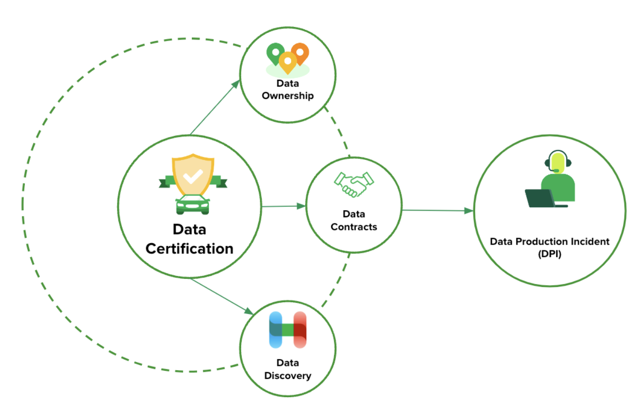
Evaluating performance impact of removing Redis-cache from a Scylla-backed service

Post Syndicated from Grab Tech original https://engineering.grab.com/evalutate-performance-remove-redis-from-scylla-service

Introduction

At Grab, we operate a set of services that manage and provide counts of various items. While this may seem straightforward, the scale at which this feature operates—benefiting millions of Grab users daily—introduces complexity. This feature is divided into three microservices: one for “writing” counts, another for handling “read” requests, and a third serving as the backend for a portal used by data scientists and analysts to configure these counters.

This article focuses on the service responsible for handling “read” requests. This service is backed by Scylla storage and a Redis cache. It also connects to a MySQL RDS to retrieve “counter configurations” that are necessary for processing incoming requests. Written in Rust, the service serves tens of thousands of queries per second (QPS) during peak times, with each request typically being a “batch request” requiring multiple lookups (~10) on Scylla.

Recently, the service has encountered performance challenges, causing periodic spikes in Scylla QPS. These spikes occur throughout the day but are particularly evident during peak hours. To understand this better, we’ll first walk you through how this service operates, particularly how it serves incoming requests. We will then explain our proposed solution and the outcomes of our experiment.

Anatomy of a request

Each counter configuration stored in MySQL has a template that dictates the format of incoming queries. For example, this sample counter configuration is used to count the raindrops for a specific city:

{
    "id": 34,
    "name": "count_rain_drops",
    "template": "rain_drops:city:{city_id}"
    ....
    ....
}

An incoming request using this counter might look like this:

{
    "key": "rain_drops:city:111222",
    "fromTime": 1727215430, // 24 September 2024 22:03:50
    "toTime": 1727400000, // 27 September 2024 01:20:00
}

This request seeks the number of raindrops in our imaginary city with city ID: 111222, between 1727215430 (24 September 2024 22:03:50) and 1727400000 (27 September 2024 01:20:00).

Another service keeps track of raindrops by city and writes the minutely (truncated at 15 minutes), hourly, and daily counts to three different Scylla tables:

  • minutely_count_table
  • hourly_count_table
  • daily_count_table

The service processing the request rounds down the time to the nearest 15 minutes. As a result, the request is processed with the following time range:

  • Start time: 24 September 2024 22:00:00
  • End time: 27 September 2024 01:15:00

Let’s assume we have the following data in these three tables for “rain_drops:city:111222”. The datapoints used in the above example request are highlighted in bold.

minutely_count_table:

key minutely_timestamp count
rain_drops:city:111222 2024-09-24T22:00:00Z 3
rain_drops:city:111222 2024-09-24T22:15:00Z 2
rain_drops:city:111222 2024-09-24T22:30:00Z 4
rain_drops:city:111222 2024-09-24T22:45:00Z 1
… … …
rain_drops:city:111222 2024-09-27T01:00:00Z 2
rain_drops:city:111222 2024-09-27T01:15:00Z 3

hourly_count_table:

key hourly_timestamp count
rain_drops:city:111222 2024-09-24T22:00:00Z 18
rain_drops:city:111222 2024-09-24T23:00:00Z 22
rain_drops:city:111222 2024-09-25T00:00:00Z 15
… … …
rain_drops:city:111222 2024-09-27T00:00:00Z 11
rain_drops:city:111222 2024-09-27T01:00:00Z 9

daily_count_table:

key daily_timestamp count
rain_drops:city:111222 2024-09-24T00:00:00Z 214
rain_drops:city:111222 2024-09-25T00:00:00Z 189
rain_drops:city:111222 2024-09-26T00:00:00Z 245
rain_drops:city:111222 2024-09-27T00:00:00Z 78

Now, let’s see how the service calculates the total count for the incoming request with “rain_drops:city:111222” based on the provided data:

Time range:

  • From: 24 September 2024 22:03:50
  • To: 27 September 2024 01:20:00

For the full days within the range, specifically 25th and 26th September, we can use data from the daily_count_table. However, for the start (24th September) and end (27th September) date of the range, we cannot use data from the daily_count_table as the range only includes portions of these dates. Instead, we will use a combination of data from the hourly_count_table and minutely_count_table to accurately capture the counts for these days.

  1. Query the daily_count_table:

    Sum (full day: 25 and 26th Sep): 189 + 245 = 434

  2. Query the hourly_count_table:
    • For 24th September (from 22:00:00 to 23:59:59):

      Hourly count: 18 + 22 = 40

    • For 27th September (from 00:00:00 to 01:00:00):

      Hourly count: 11

  3. Query the minutely_count_table:

    For 27th September (from 01:00:00 to 01:15:00):

    Minutely count: 2

  4. Total count:

    Total = Daily count (25th and 26th) + Hourly count (24th) + Hourly count (27th) + Minutely count (27th)

    = 434 + 40 + 11 + 2

    = 487

Figure 1: The example request for “rain_drops:city:111222” is handled using data from three different Scylla tables.

As shown in the calculation, when the service receives the request, it comes up with the total count of raindrops by querying three Scylla tables and summing them up using some specific rules within the service itself.

Querying the cache

In the previous section, we explained how Scylla handles a query. If we cached the response for the same request earlier, retrieval from the cache follows a simpler logic. For instance, for the example request, the total count is stored using the floored start and end times (rounded to the nearest 15-minute window within an hour), which was used for the Scylla query instead of the original time in the request. The cache key-value pair would look like this:

  • key: id:34:rain_drops:city:111222:1727215200:1727399700
  • value: 487

Timestamps 1727215200 and 1727399700 represent the adjusted start and end times of 24 September 2024 22:00:00 and 27 September 2024 01:15:00, respectively. It has a Time-To-Live (TTL) of 5 minutes. During this TTL window, any request for the key “rain_drops:city:111222” having the same start and end times (after rounding to the nearest 15 minutes) will be read from the cache instead of querying Scylla.

For example, for the following three start times, although they are different, after flooring the request to the nearest 15 minutes, the start time becomes 24 September 2024 22:00:00 for all of them, which is the same start time as the one in the cache.

  • 24 September 2024 22:01:00
  • 24 September 2024 22:02:00
  • 24 September 2024 22:06:00

In day-to-day operations, this caching setup allows roughly half of our total production requests to be served by the Redis cache.

Figure 2. The graph visualises the relative quantity of cache hits vs Scylla-bound requests.

Problem statement

The setup consisting of Scylla and Redis cache works well. Particularly because Scylla-bound queries need to look up 1-3 tables (minutely, hourly, daily, depending on the time range) and perform the summation as explained earlier, whereas a single cache lookup gets the final value for the same query. However, as our cache key pattern follows the 15-minute truncation strategy, along with a 5-minute cache TTL, it leads to an interesting phenomenon – our cache hits plummet and Scylla QPS spikes at the end of every 15 minutes.

Figure 3. Graph showing 15-minute spikes in Scylla-bound requests accompanied by a decline in cache hit rates.

This occurs primarily due to the fact that almost all requests to our service are for recent data. Due to this, at the end of every 15-minute block within an hour (i.e., 00, 15, 30, 45), most of the requests require creating new cache keys for the latest 15-minute block. At this point in time, there may be many unexpired (i.e., have not reached 5 min TTL) cache keys from the previous 15-minutes block, but they become less relevant as most requests are asking for recent data.

The table in Figure 4 shows example data for configurations “rain_drops:city:111222” and “bird_sighting:city:333444”. For these two configurations, new cache keys are created due to TTL expiry at random times. However, at the end of the 15-minute block, which, in this case is at the end of 22:00-22:15 block, both configurations need new cache keys for the new 15-minute time block that has just started (i.e., start of 22:15-22:30), even though some of their cache keys from the previous 15-minute block are still valid. This requirement of creating new cache keys for most of the requests at the end of a 15-minute block causes spikes in Scylla QPS and a sharp decline in cache hits.

One question that arises is – “Why don’t we see a spike every 5 minutes for cache key TTL expiry?” This is because, within the 15 minutes block, new cache keys are continuously created when a key reaches TTL and a new request for that is received. Since this happens all the time as shown in Figure 4, we do not see a sharp spike. In other words, although Scylla does receive more queries due to cache TTL expiry, it does not lead to a spike in Scylla queries or a sharp drop in cache hits. This is because the cache keys are always being created and invalidated due to TTL expiry instead of following a fixed 5-minute block similar to the 15-minute block we use for our truncation strategy.

Figure 4. This table visualises scenarios when new cache keys are required due to TTL expiry vs due to 15-minute truncation strategy.

These Scylla QPS spikes at the end of every 15-minute block lead to a highly imbalanced Scylla QPS. This often causes high latency in our service during the 15-minute blocks that fall within the peak traffic hours. This further causes more requests to time out, eventually increasing the number of failed requests.

Proposed solution

We propose mitigating this issue by completely removing the Redis-backed caching mechanism from the service. Our observations indicate that the Scylla spikes at the end of 15-minute blocks occur due to cache hit misses. Therefore, removing the caching should eliminate the spikes and provide for a more balanced load.

We acknowledge that this may seem counterintuitive from an overall performance standpoint as removing caching means all queries will be Scylla-bound, potentially impacting the overall performance since caching usually speeds up processes. In addition, caching also comes with an advantage where for cache hits, the service does not need to do the summation on Scylla results from minutely, hourly, and the daily table. Despite these shortcomings, we hypothesise that removing caching should not have an adverse impact on the overall performance. This is based on the fact the Scylla has its own sophisticated caching mechanism. However, our existing setup uses Redis for caching, underutilising Scylla’s cache as the most subsequent queries hit the Redis cache instead.

In summary, we propose eliminating the Redis caching component from our current architecture. This change is expected to resolve the Scylla query spikes observed at the end of every 15-minute block. By relying on Scylla’s native caching mechanism, we anticipate maintaining the service’s overall performance more effectively. The removal of Redis is counterbalanced by the optimised utilisation of Scylla’s built-in caching capabilities.

Experiment

Procedure

The experiment was done on an important live service serving thousands of QPS. To avoid disruptions, we followed a gradual approach. We first turned off caching for a few configurations. If there were no adverse impacts observed, we incrementally disabled cache for more configurations. We controlled the rollout increment by using a mathematical operator on the configuration IDs. This approach is simple and allows us to deterministically disable the cache for specific configurations across all requests, as opposed to using a percentage rollout which randomly disables the cache for different configurations across different requests. This is also due to the fact that the number of configurations is relatively steady and small (less than a thousand). Since these configurations are already fully cached in the service memory from RDS, there will be no performance impact of having a condition that operates on these configurations.

To make sense of the graphs and metrics reported in this section, it is important to understand the traffic pattern of this service. The service usually sees two peaks every day: noon and another around 6-7 PM. On a weekly basis, we usually see the highest traffic on Friday, with the busiest period being from 6-8 PM.

In addition, the timeline of when and how we made various changes to our setup is important to accurately interpret our results.

Experiment timeline: Nov 5 – Nov 13, 2024:

  • Redis cache disabled for ~5% of the counter configurations – Nov 5, 2024, 10.26 AM (Canary started: 10.00 AM)

  • Redis cache disabled for ~25% of the counter configurations – Nov 5, 2024, 12.44 PM (Canary started: 12.20 PM)

  • Redis cache disabled for ~35% of the counter configurations – Nov 6, 2024, 10.50 AM (Canary started: 10.21 AM)

  • Redis cache disabled for ~75% of the counter configurations – Nov 7, 2024, 10.53 AM (Canary started: 10.26 AM) 

  • Experimenting with running a major compaction job during the day time: Tue, Nov 12, 2024, between 2-5 PM (on all nodes)

  • Day time scheduled major compaction job starts from: Tue, Nov 13, 2024, between 2-5 PM (on all nodes)

  • Redis cache disabled for 100% of the counter configs – Wed, 13 Nov 2024, 10:56 AM (Canary started: 10:32 AM)

Unless otherwise specified, the graphs and metrics we report in this article uses this fixed time window: Oct 31 (Thu) 12.00 AM – Nov 15 (Friday) 11.59 PM SGT. This time window covers the entire experiment period with some buffer to observe the experiment’s impact.

Observations

As we progressively disabled read from external Redis cache over the span of 8 days (Nov 5 – Nov 13), we made interesting observations and experimented with some Scylla configuration changes on our end. We describe them in the following sections.

Scylla hit vs. cache hit

As we progressively disabled Redis cache for most of the counters, one obvious impact was the gradual increase in Scylla-bound QPS and similar decrease in Redis-cache hit. When Redis-cache was enabled for 100% of the configurations, 50% of the requests were bound for Scylla and the other 50% were for Redis. At the end of the experiment, after fully disabling Redis cache, 100% of the requests were Scylla-bound.

Figure 5. Gradual increase in Scylla QPS and simultaneous decrease in Redis cache hit.

15-minutes and hourly spikes

We noticed that the 15-minute spikes in Scylla QPS as well as the associated latency slowly became less prominent and eventually disappeared from the graph after we completely disabled the Redis cache. However, we noticed that the hourly spike still remained. This is attributed to the higher QPS from the clients calling this service at the turn of every hour. As a result, limited optimisation can be done to reduce the hourly spike on this service’s end.

Figure 6. The 15-minute spikes in Scylla QPS disappeared after the external Redis cache was fully disabled. This graph uses a smaller time window to show the earlier spikes. It also shows the persistence of hourly spikes after the experiment which is attributed to the clients of this service sending more requests at the start of every hour.
Figure 7. The graph shows that the 15-minute spikes in Scylla’s latency disappeared after the external Redis cache was fully disabled. This graph uses a smaller time window to show the earlier spikes. It also shows the persistence of hourly spikes in latency after the experiment which is attributed to the clients of this service sending more requests at the start of every hour.

Service latency and additional Scylla compaction job

When we disabled Redis cache for about 75% of the counters configurations on Nov 7 (which accounts for about 85% of the overall QPS), we noticed an increase in the overall average service latency, from between 6-8 ms to 7-12 ms (P99 went from ~30-50ms to ~30-70ms). This caused a spike in open circuit breaker (CB) events on Hystrix. At this point, before disabling cache for more counters, on Nov 12, we experimented with running an additional major compaction job on Scylla between 2-5 PM on all our Scylla nodes, progressively on each availability zone (AZ). It is noteworthy that we already have a scheduled major compaction job that runs around 3 AM every day. The outcome of this experiment was quite positive. It brought back the average and P99 latency almost to the prior level when we had Redis cache enabled for 100% of the counters. This also had a similar effect on the Hystrix CB open events. Based on this observation, we made this additional day time major compaction job as a daily scheduled job. We disabled Redis cache for 100% of the counters the next day (Nov 13). This expectedly increased the Scylla QPS, with no noticeable adverse effect on the service latency or Hystrix CB open events.

Figure 8. This graph shows how the average latency changed as a result of the experiment. The higher spikes correspond to the time when Redis cache was being progressively disabled before introducing the day time Scylla compaction job. The spikes lessened after the compaction job was introduced on Nov 12 (Note: Friday spike was due to higher traffic in general).
Figure 9. This graph shows how the P99 latency changed as a result of the experiment. The higher spikes correspond to the time when Redis cache was being progressively disabled before introducing the day time Scylla compaction job. The spikes lessened after the compaction job was introduced on Nov 12 (Note: Friday spike was due to higher traffic in general).

Scylla’s own cache

One of our hypotheses was that we were not using Scylla cache due to our system’s design, along with all the service specific characteristics discussed earlier. Our experimental results show that this is indeed the case. We observed a significant increase in Scylla reads with Scylla’s own cache hits, while Scylla reads with Scylla’s own cache misses remained about the same despite our Scylla cluster receiving double the traffic. Percentage-wise, before disabling the external Redis cache, Scylla hit its own cache for ~30% of the total reads, and after we have completely disabled the external Redis cache, Scylla hit its cache for about 70% of the reads. We believe that this largely contributes to the overall performance of the service despite fully decommissioning the expensive Redis cache component from our system architecture.

Figure 10. Significant increase in Scylla reads after disable Redis cache.
Figure 11. No change in Scylla cache miss despite the doubling of Scylla traffic.

Scylla CPU and memory usage

Contrary to our assumption, although the Scylla QPS doubled due to the change done as part of this experiment, there was marginal increase in Scylla CPU usage (from ~50% to ~52% at peak). In terms of memory, Scylla log-structured allocator (LSA) memory usage remains consistent. For Non-LSA memory, the maximum utilisation did not increase. However, we noticed two daily spikes instead of one existed before the experiment. The second spike results from the newly added daily major compaction job. Notably,the overall non-LSA peak has slightly decreased after the introduction of the new compaction job.

Figure 12. Relatively steady Scylla CPU utilisation.
Figure 13. Non-LSA memory usage spikes twice a day after the experiment. The new spike corresponds to the newly added day time compaction job.

Conclusion

In summary, we were able to maintain the same service performance while removing an expensive Redis cache component from our system architecture, which accounted for about 25% of the overall service cost. This has been made possible primarily by significant increase in the utilisation of Scylla’s own cache and adding a daily major compaction job on all our Scylla nodes.

In the future, we plan to further experiment with different Scylla configurations for potential performance gain, specifically to improve the latency.

Join us

Grab is a leading superapp in Southeast Asia, operating across the deliveries, mobility and digital financial services sectors. Serving over 800 cities in eight Southeast Asian countries, Grab enables millions of people everyday to order food or groceries, send packages, hail a ride or taxi, pay for online purchases or access services such as lending and insurance, all through a single app. Grab was founded in 2012 with the mission to drive Southeast Asia forward by creating economic empowerment for everyone. Grab strives to serve a triple bottom line – we aim to simultaneously deliver financial performance for our shareholders and have a positive social impact, which includes economic empowerment for millions of people in the region, while mitigating our environmental footprint.

Powered by technology and driven by heart, our mission is to drive Southeast Asia forward by creating economic empowerment for everyone. If this mission speaks to you, join our team today!
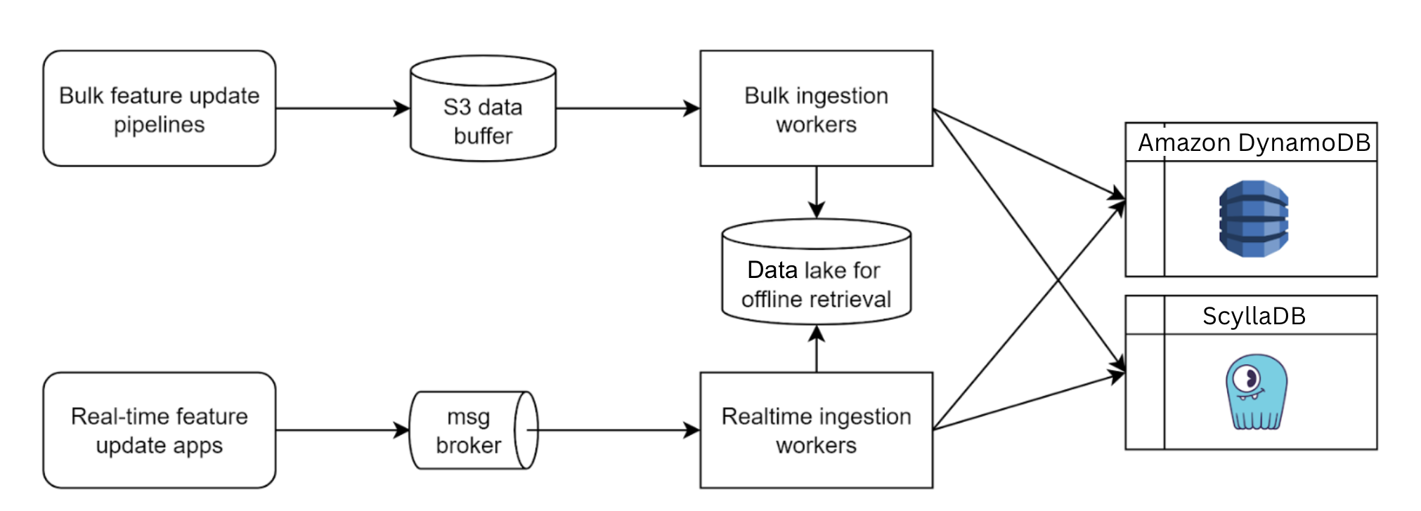
Facilitating Docs-as-Code implementation for users unfamiliar with Markdown

Post Syndicated from Grab Tech original https://engineering.grab.com/facilitating-docs-as-code-with-markdown

Introduction

Although Grab is a tech company, not everyone is an engineer. Many team members don’t use GitLab daily, and Markdown’s quirks can be challenging for them. This made adopting the Docs-as-Code culture a hurdle, particularly for non-engineering teams responsible for key engineering-facing documents. In this article, we’ll discuss how we’ve streamlined the Docs-as-Code process for technical contributors, specifically non-engineers, who are not very familiar with GitLab and might face challenges with Markdown. For more on the benefits of the Docs-as-Code approach, check out this blog on the subject.

As part of our ongoing efforts to enhance the TechDocs experience, we’ve introduced a rich text editor for those who prefer a WYSIWYG (What You See Is What You Get) interface on top of a Git workflow, helping to simplify authoring. We’ll also cover how we plan to improve the workflow for non-engineering teams contributing to service and standalone documentation.

The need for a rich text editor

Ask any developer today, and they’ll likely tell you that Markdown is the go-to format for documentation. Due to its simplicity, whether it’s GitHub, GitLab, Bitbucket, or other platforms, Markdown has become the default choice, even for issue tracking. It’s also integrated into most text editors, like IntelliJ, VS Code, Vim, and Emacs, with handy plugins for syntax highlighting and previewing.

Engineers are gradually embracing the Docs-as-Code approach and enjoying the benefits of writing the documentation in Markdown format directly in their IDEs and pushing them out as merge requests (MR). However, non-engineers face the nuance of writing in Markdown and going through the Git workflow. This is when the call for a WYSIWYG (What You See Is What You Get) editor aka TechDocs editor came about. This solution brought about several benefits to non-engineers. It provides a familiar, UI-based experience for editing, but it still aligns with the Docs-as-Code model. This tool allows users to edit documentation via a simple UI in the Backstage portal without having to deal with the complexities of MkDocs, entity catalogs, or Markdown syntax. In the context Backstage, “entities” refer to services, platforms, tools, or libraries, and documentation is often tied to these entities to provide context sensitivity. The goal was to make it easy for people to focus on content, not the tools, and enable quick updates without the technical overhead.

We’ve kept GitLab as the central storage system, but now, with the TechDocs editor, non-engineers can contribute with ease. Figure 1 highlights our editor’s features:

  • Reordering
  • Renaming
  • Deleting pages
  • Switching between normal and Markdown views
  • Formatting text with titles, bullets, numbering
Figure 1: TechDocs editor in Helix TechDocs portal

Our goal for our editor is to make it more flexible, performant, and user-friendly. Based on user feedback, key priorities include customisation, extensibility for non-standard Markdown elements, and long-term maintainability.

To achieve this, we selected the Lexical framework. Compared to other Markdown-based tools like Toast UI, Lexical offers greater extensibility, allowing us to implement advanced features such as autocomplete and support for non-standard Markdown elements like Kroki diagrams.

The following flowchart illustrates how Markdown content is imported and exported within the Lexical editor, ensuring seamless integration with TechDocs.

Figure 2: Lexical Markdown transformer flow chart

By continuously iterating based on user needs, we aim to make Docs-as-Code accessible not just for engineers but for anyone contributing to documentation at Grab.

User journeys

We explored various workflows to streamline the documentation lifecycle, focusing on both creation and editing processes. By integrating these workflows into the developer portal, we ensured that users can easily create and edit documentation, enhancing overall efficiency and collaboration.

Here are the three key user journeys we focused on addressing:

Journey 1: Edit existing TechDocs

High level workflow definition:

  1. Toggle to ‘edit’ mode: The user switches to the edit mode to start making changes to the TechDocs.
  2. User starts editing TechDocs: The user begins the process of editing the documentation and clicks save.
  3. User gets redirected to GitLab: If not authenticated, they are redirected to GitLab for authentication. Once authenticated, a merge request is created to update the entity YAML file and add the new TechDocs.
  4. Access check: The system checks if the user has access to the TechDocs file repository. If not, they are prompted to request access.
Figure 3: User journey 1

Journey 2: Create stand-alone TechDocs from “Documentation” page

High level workflow definition:

  1. User authentication:
    • If the user is not authenticated, they are redirected to GitLab for authentication.
    • If the user is already authenticated, the process skips to the next step.
  2. Registering merge requests:
    • The MR is registered to a scheduler job to automatically register a new entity catalog when it detects that the MR has been merged.

This workflow ensures that users are authenticated via GitLab before proceeding and that new entity catalogs are automatically registered upon the merging of MRs.

Figure 4: User journey 2

Journey 3: Create TechDocs from “Docs” tab on entity page

High level workflow definition:

  1. Start creating TechDocs:
    • User selects ‘create TechDocs’ on the ‘Docs’ tab in the Helix TechDocs portal UI.
  2. Save and redirect:
    • User clicks ‘save’ and is redirected to GitLab with a merge request (MR) created to update the entity YAML file and add new TechDocs.
  3. Access check and MR registration:
    • If the user has access to the entity YAML file repository, proceed with the MR. If not, prompt the user to get access.
    • Register the MR to a scheduler job to automatically refresh the entity catalog when it detects the MR as merged.
Figure 5: User journey 3

Phased rollout

We phased the rollout of our Markdown editor to ensure a smooth transition, allowing users to gradually adapt while we gathered feedback and iterated on features. This approach helped us address challenges early, refine usability, and deliver meaningful improvements with each phase.

Phase 1: Initial Markdown editor for developer portal

In Phase 1, we built a basic editor aligned with our documentation standards. Users can create and edit TechDocs for different entity catalogs, with support for basic Markdown and image previews for both absolute and relative paths. The editor tracks concurrent editing sessions and shows pending merge requests. It also includes Markdown configuration options to add, rename, reorganise, or delete pages. Additionally, our GitLab integration consolidates changes into a single commit and opens a merge request.

Phase 2: Independent documentation creation

Phase 2 includes expanded functionality to support independent documentation creation and related features, such as:

  • HTML preview and image uploads (relative paths).
  • Save drafts locally in the browser.
  • Pending MRs listed in the editor.
  • Draw.io and Excalidraw integration for diagrams.
  • MkDocs updates: change site name.
  • Auto-registeration of new entity catalogs when MRs are merged.

Phase 3: Advanced editor capabilities

Phase 3 introduced additional features, such as:

  • Support for Kroki / Mermaid diagrams.
  • Display concurrent edit sessions for better collaboration.

Each phase improved the editor, enhancing TechDocs at Grab with seamless GitLab integration and user-friendly features.

Integrating the ability to do a live preview

While syntax highlighting in the TechDocs editor is helpful, it can’t fully predict how the final Markdown document will appear once rendered due to Markdown flavour inconsistencies. This is especially true for elements like images, tables, and diagrams, where visual verification is crucial. To minimise these risks, the TechDocs editor includes a live preview feature, allowing users to see the fully rendered document alongside the editor in a split-screen view. This lets users verify their work as they go, preventing the need to switch back and forth between the editor and the final document, saving time and reducing potential formatting errors.

However, like most live preview features, performance challenges can arise. For larger documents, the process of continuously converting Markdown to HTML can slow down editing. External resources such as images that need to be re-rendered, can cause visual glitches or delays in the preview. Running scripts or using plugins with extended grammar also adds to the performance load, requiring frequent re-execution and potentially slowing down the experience.

To mitigate these issues, the TechDocs editor uses an inbuilt preview feature that shows users exactly how their changes are going to appear on the portal once their changes are merged. This ensures that users can confidently make adjustments and understand the final presentation before committing their updates. Additionally, the live preview feature enables more efficient collaboration by providing real-time feedback on content and formatting, further enhancing the overall documentation workflow.

GitLab integration strategy

The TechDocs editor integrates seamlessly with GitLab, allowing users to make changes effortlessly through OAuth2 authentication. When users log into the editor, they simply click the “Connect with GitLab” button, which provides access via the OAuth 2.0 protocol. Once connected, all modifications made within the editor are executed using the user’s GitLab credentials, streamlining the documentation process and ensuring a smooth experience for users as they update their documentation directly within the TechDocs framework.

To minimise Git conflicts, we considered and implemented some of these approaches:

  • Display pending merge requests at the top of the editor to alert users of existing changes.
  • Show who else is editing the same TechDocs to help users coordinate and avoid conflicts.
  • Include tools to automatically or semi-automatically resolve Git conflicts.

Conclusion

Bringing Docs-as-Code to a broader audience at Grab meant addressing the challenges faced by non-engineering contributors. With the introduction of a WYSIWYG editor, seamless GitLab integration, and a live preview feature, we’ve made it easier for everyone to contribute without needing deep Markdown expertise.

As we continue to improve the TechDocs editor, our focus remains on removing barriers to documentation, enhancing collaboration, and ensuring that our docs evolve alongside our fast-moving engineering teams.

Docs-as-Code isn’t just about engineers writing documentation—it’s about making documentation a natural and frictionless part of the development process for everyone.

Join us

Grab is a leading superapp in Southeast Asia, operating across the deliveries, mobility and digital financial services sectors. Serving over 800 cities in eight Southeast Asian countries, Grab enables millions of people everyday to order food or groceries, send packages, hail a ride or taxi, pay for online purchases or access services such as lending and insurance, all through a single app. Grab was founded in 2012 with the mission to drive Southeast Asia forward by creating economic empowerment for everyone. Grab strives to serve a triple bottom line – we aim to simultaneously deliver financial performance for our shareholders and have a positive social impact, which includes economic empowerment for millions of people in the region, while mitigating our environmental footprint.

Powered by technology and driven by heart, our mission is to drive Southeast Asia forward by creating economic empowerment for everyone. If this mission speaks to you, join our team today!
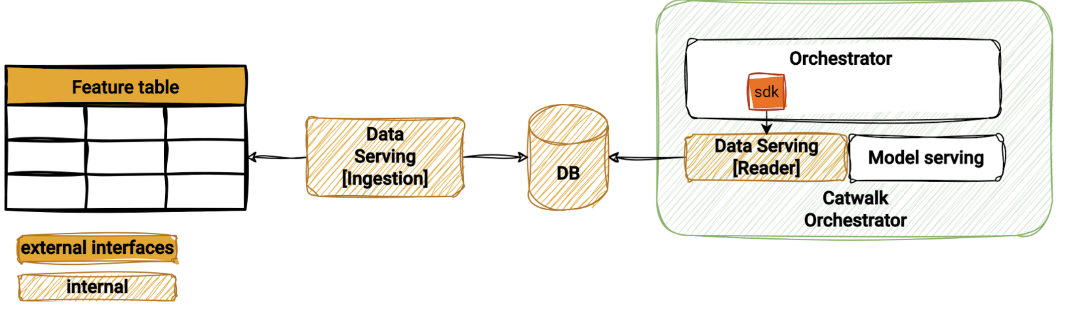
Improving Hugo stability and addressing oncall challenges through automation

Post Syndicated from Grab Tech original https://engineering.grab.com/improving-hugo-stability

Introduction

Hugo plays a pivotal role in enabling data ingestion for Grab’s data lake, managing over 4,000 pipelines onboarded by users. The stability of Hugo pipelines is contingent upon the health of both the data sources and various Hugo components. Given the complexity of this system, pipeline failures occasionally occur, necessitating user intervention when retry mechanisms prove insufficient. These incidents present challenges such as:

  • Limited user visibility into pipeline issues.
  • Uncertainty about resolution steps due to extensive documentation.
  • An overwhelmed Hugo on-call team dealing with ad-hoc requests and growing infrastructure dependencies.
  • Raised Data Production Issues (DPIs) lacking clear Root Cause Analysis (RCA), hindering effective management.

Such challenges ultimately increase data downtime due to prolonged issue triage and resolution times.

To address these problems, we conducted a thorough analysis of failure modes and the efforts required to resolve them. Based on our findings, we propose a comprehensive automation solution.

This blog outlines the architecture and implementation of our proposed solution, consisting of modules like Signal, Diagnosis, RCA Table, Auto-resolution, Data Health API, and Data Health WorkBench, each with a specific function to enhance Hugo’s monitoring, diagnosis, and resolution capabilities.

The blog further details the impact of these automated features, such as enhanced data visibility, reduced on-call workload, and concludes with our next steps, which focus on advancing auto-resolution strategies, enriching the Data Health Workbench, and broadening diagnostics to include more infrastructure components, like Flink, for comprehensive coverage.

Architecture details

We designed the solution based on these principles:

  1. Identify different failure modes based on past issues and analysis from first principles.
  2. Analyse temporal relationships of pipeline execution steps to diagnose issues to failure modes.
  3. Focus on auto-resolution, and add additional features to cover gaps which can’t be immediately addressed by auto-resolution or diagnosis.

The following diagram shows the solution we proposed.

Figure 1. Architecture

The architecture consists of five core modules, each with a specific function:

  1. Signal module: This module is responsible for collecting signals. It gathers three different types of signals that collectively define the health status of the data lake table. The signals include:
    • Failure callback signal: This indicates whether the pipeline runs involving this data lake table are successful or not.
    • SLA alert signal: This indicates whether the pipeline execution involving this data lake table meets the Service Level Agreement (SLA). For an hourly batch job, the expectation is to complete within one hour.
    • Data quality test failure signal: This represents various types of completeness checks to ensure that data lake tables are consistent with the source tables based on their pipeline strategies.
  2. Diagnosis module: This is the core module responsible for diagnosing the root cause of 3 types of failures collected in the Signal module. It determines:
    • The root cause of the failure.
    • The assignee responsible for fixing the error.
    • The auto-resolution method to fix the issue.
    • Manual resolution steps if the auto-resolution fails.
  3. RCA table: This module stores the following information:
    • Signals
    • Assignee information
    • Diagnosis results
    • Auto-resolution methods
    • Manual resolution steps
  4. Auto-resolution module: This module executes the auto-resolution methods to resolve issues automatically.
  5. Data health API: This module provides API access to other platforms. External platforms or pipelines that rely on Hugo onboarded tables can subscribe to the health status and investigate the root cause when a table is deemed unhealthy.
  6. Hugo pipeline health dashboard: A centralised dashboard for Hugo users to visualise the health status of tables, auto resolution status, and manual fix button.

By leveraging these modules, the architecture ensures robust monitoring, diagnosis, and resolution of issues, leading to improved data health and operational efficiency.

Implementation

Signal module

There are two methods for generating these three signals. The failure signal is generated through an airflow callback, while the SLA miss and data completeness test signals are produced by Genchi. Genchi is a data quality observability platform at Grab that performs data quality checks and acts as a crucial enabler for the enforcement of data contracts.

Diagnosis module

As soon as an alert is created, the diagnosis begins. To avoid lengthy diagnosis times, Hugo has developed an innovative approach that eliminates the requirement for parsing extensive logs, such as Spark executor logs or Airflow logs. Instead, it gathers signals transmitted by the computation engine or Grab’s internal platforms.

The diagnosis process can be time-consuming, even with efforts to reduce the time it takes. For example, the SLA diagnoser uses multiple analysers that run sequentially, and some of these analysers (like the Airflow analyser) make API calls that can take a significant amount of time. The more analysers that are involved in the diagnosis process, the longer it can take.

Figure 2. Diagnosis process

Parallelism in diagnosis serves as a solution to lower the overall latency when there is a surge in error traffic. The degree of parallelism differs based on the type of signal. For example, the failure signal diagnosis can be executed in thousands of processes at once, while for SLA miss and data quality test failures signals, the parallelism is determined by the number of partitions in the Kafka topic since these signals are received from Kafka.

Auto-resolution module

Auto-resolution is a flexible framework that enables the implementation of custom handlers for various types of failures. One of the common handlers employs a retry mechanism with backoff for transient errors. For instance, if Hugo receives a failure callback indicating that the root cause is a database replica lag, it would wait for an hour before re-triggering the job. This auto-resolution process runs asynchronously with the diagnosis process.

Data health API

The data health information includes a unique identifier, current status, error details, and the time of the last health check, providing a comprehensive snapshot of the dataset’s health.

Hugo converts the detailed information available in its internal data health API to the data health API specification format to be consumed by Kinabalu, our internal system designed to automate and streamline incident management processes by integrating with multiple systems such as Slack, Jira, Splunk on-call, and Datadog.

Hugo pipeline health dashboard

The Data Health Workbench is a centralised dashboard for Hugo users to visualise the health status of tables, auto-resolution status, and manual fix buttons. It provides a comprehensive view of data health and facilitates efficient issue resolution.

The key features are as follows:

  1. Health status visualisation: Displays the current health status of tables, making it easy to identify unhealthy tables.
  2. Assignee information: Indicates the assignee responsible for fixing the issue, ensuring clear accountability.
  3. How-to-fix guide: Provides step-by-step instructions on how to resolve the issue, empowering users to take immediate action.
  4. Action: Offers an action button to initiate the resolution process with a single click, streamlining issue resolution.
  5. Admin feature with detailed diagnosis information: Provides admins supplementary information, including the reasoning behind the root cause identification and assignee determination, which allows for a deeper understanding of the root cause of issues.

By leveraging the Data Health Workbench, Hugo users can efficiently monitor and manage data health, ensuring data integrity and operational efficiency.

Figure 3. Data Health Workbench

Impact

The implementation of Hugo’s auto-healing and diagnosis features has resulted in significant improvements in stability and operational efficiency for our data pipelines. Here are some key outcomes:

  • Enhanced data visibility: We’ve improved the visibility into the health of datasets, allowing for quick identification of issues and more informed decision-making.
  • Timely resolution of data issues: With automated diagnostic and resolution processes, we ensure that data issues are addressed promptly, minimising data downtime and enhancing overall data availability.
  • Reduced on-call workload: By automating many of the common failure resolutions, the workload on Hugo on-call teams has been significantly reduced. This allows teams to focus on more complex and impactful tasks.
  • Scalable solution for managing complexity: The auto-resolution framework is well-equipped to handle the increasing complexity of data infrastructure, offering scalable solutions for transient errors through custom handlers and retry mechanisms.
  • Improved data contract management: By providing detailed pipeline health information via the Data Health API, we enable precise and accurate DPIs, complete with root cause analysis and assignee information, enhancing the management and resolution of data contract breaches.
  • Valuable reference for other platforms: The insights and methodologies developed through this initiative provide a valuable reference for other platform teams at Grab looking to implement similar automation and diagnostic capabilities.
  • Support for Grab’s success: These enhancements support Grabbers by ensuring easy access to the datasets they need and contribute to the overall success of Grab through reliable data availability.

Next steps

Our next steps involve advancing auto-resolution strategies by focusing on complex solutions like pipeline runtime optimisation to boost efficiency and minimise processing delays. We will enrich the Data Health Workbench with detailed information, enabling users to visualise and understand pipeline health more effectively and make informed corrective actions. Additionally, we plan to broaden our diagnosis capabilities by integrating more infrastructure components, such as Flink health information, to ensure a comprehensive and holistic monitoring approach for all engines within Hugo.

Join us

Grab is a leading superapp in Southeast Asia, operating across the deliveries, mobility and digital financial services sectors. Serving over 800 cities in eight Southeast Asian countries, Grab enables millions of people everyday to order food or groceries, send packages, hail a ride or taxi, pay for online purchases or access services such as lending and insurance, all through a single app. Grab was founded in 2012 with the mission to drive Southeast Asia forward by creating economic empowerment for everyone. Grab strives to serve a triple bottom line – we aim to simultaneously deliver financial performance for our shareholders and have a positive social impact, which includes economic empowerment for millions of people in the region, while mitigating our environmental footprint.

Powered by technology and driven by heart, our mission is to drive Southeast Asia forward by creating economic empowerment for everyone. If this mission speaks to you, join our team today!
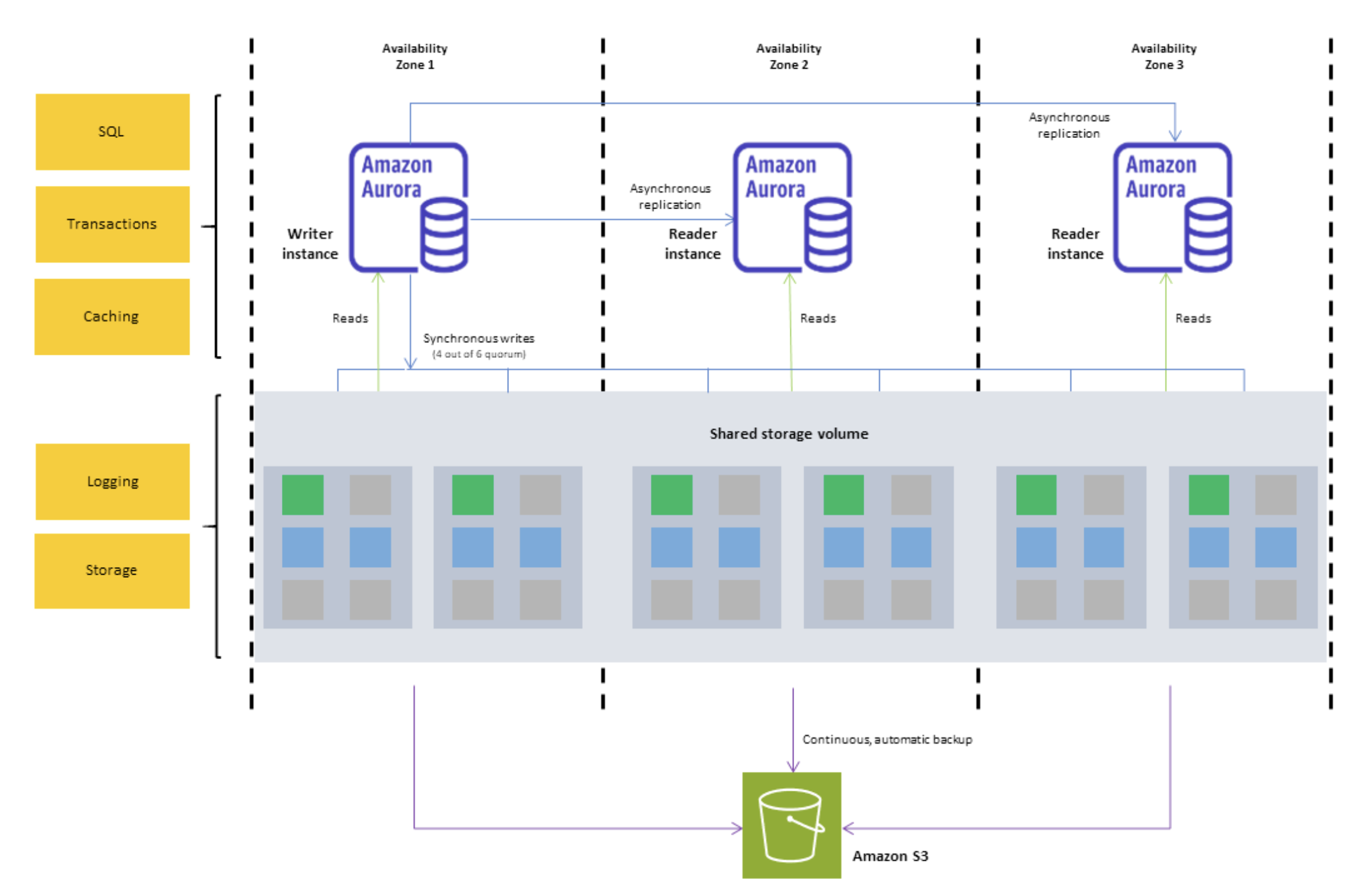
Building a Spark observability product with StarRocks: Real-time and historical performance analysis

Post Syndicated from Grab Tech original https://engineering.grab.com/building-a-spark-observability

Introduction

At Grab, we’ve been working to perfect our Spark observability tools. Our initial solution, Iris, was developed to provide a custom, in-depth observability tool for Spark jobs. As described in our previous blog post, Iris collects and analyses metrics and metadata at the job level, providing insights into resource usage, performance, and query patterns across our Spark clusters.

Iris addresses a critical gap in Spark observability by providing real-time performance metrics at the Spark application level. Unlike traditional monitoring tools that typically provide metrics only at the EC2 instance level, Iris dives deeper into the Spark ecosystem. It bridges the observability gap by making Spark metrics accessible through a tabular dataset, enabling real-time monitoring and historical analysis. This approach eliminates the need to parse complex Spark event log JSON files, which users are often unable to access when they need immediate insights. Iris empowers users with on-demand access to comprehensive Spark performance data, facilitating quicker decision-making and more efficient resource management.

Iris served us well, offering basic dashboards and charts that helped our teams understand trends, discover issues, and debug their Spark jobs. However, as our needs evolved and usage grew, we began to encounter limitations:

  1. Fragmented user experience and access control: Observability data is split between Grafana (real-time) and Superset (historical), forcing users to switch platforms for a complete view. The complex Grafana dashboards, while powerful, were challenging for non-technical users. The lack of granular permissions hindered wider adoption. We needed a unified, user-friendly interface with role-based access to serve all Grabbers effectively.

  2. Operational overhead: Our data pipeline for offline analytics includes multiple hops and complex transformations.

  3. Data management: We faced challenges managing real-time data in InfluxDB alongside offline data in our data lake, particularly with string-type metadata.

These challenges and the need for a centralised, user-friendly web application prompted us to seek a more robust solution. Enter StarRocks – a modern analytical database that addresses many of our pain points:

Pain points with InfluxDB StarRocks solution
Limited SQL compatibility: Requires use of Flux query language instead of full SQL Full MySQL-compatible SQL support, enabling seamless integration with existing tools and skills
Complex data ingestion pipeline: Requires external agents like Telegraf to consume Kafka and insert into InfluxDB Direct Kafka ingestion, eliminating the need for intermediate agents and simplifying the data pipeline
Limited pre-aggregation capabilities: Aggregation is limited to time windows and indexed columns, not string columns Flexible materialised views supporting complex aggregations on any column type, improving query performance
Poor support for metadata and joins: Designed primarily for numerical time series data, with slow performance on string data and joins Efficient handling of both time-series and string-type metadata in a single system, with optimised join performance
Difficult integration with data lake: There is no official way to backup or stream data directly to the datalake, requiring separate pipelines Native S3 integration for easy backup and direct data lake accessibility, eliminating the need for separate ingestion pipelines
Performance issues with high cardinality data: Indexing unique identifiers (like app\_id) causes huge indexes and slow queries Optimised for high cardinality data, allowing efficient querying on unique identifiers without performance degradation

In this blog post, we will dive into leveraging StarRocks to build the next generation of the Spark observability platform. We will explore the architecture, data model, and key features that are helping us overcome previous limitations and provide more value to Spark users at Grab.

System architecture overview

In the journey to enhance user experience, we’ve made substantial changes to the architecture, moving from the Telegraf/InfluxDB/Grafana (TIG) stack to a more streamlined and powerful setup centered around StarRocks. This new architecture addresses the previous challenges and provides a more unified, flexible, and efficient solution.

Figure 1. New Iris architecture with StarRocks integration

Key Components of the new architecture:

1. StarRocks database

  • Replaces InfluxDB for both real-time and historical data storage

  • Supports complex queries on metrics and metadata tables

2. Direct Kafka ingestion

  • StarRocks ingests data directly from Kafka, eliminating Telegraf

3. Custom web application (Iris UI)

  • Replaces Grafana dashboards

  • Centralised, flexible interface with custom API

4. Superset integration

  • Maintained and now connected directly to StarRocks

  • Provides real-time data access, consistent with the custom web app

5. Simplified offline data process

  • Scheduled backups from StarRocks to S3 directly

  • Replaces previous complex data lake pipelines

Key improvements:

1. Unified data store: Single source for real-time and historical data

2. Streamlined data flow: A simplified pipeline reduces latency and failure points

3. Flexible visualisation: Custom web app with intuitive, role-specific interfaces

4. Consistent real-time access: Across both custom app and Superset

5. Simplified backup and data lake integration: Direct S3 backups

Data model and ingestion

The Iris observability system is designed to monitor both job executions and ad-hoc cluster usage, encompassing what we call “cluster observation”. This model accounts for two scenarios:

  • Adhoc use: Pre-created clusters shared among team users

  • Job execution: New clusters are created for each job submission

Key design points

For each cluster, we capture both metadata and metrics:

Key point Description
Linkage We use worker\_uuid to link metadata with worker metrics app\_id to link metadata with Spark event metrics.
Granularity Worker metrics are captured every 5 seconds, linked by worker\_uuid. Spark events are captured as they occur, linked by app\_id. Metadata can be captured multiple times.
Flexibility This schema allows for queries at various levels: Individual worker level, job level, cluster level.
Historical analysis The design enables insights from historical runs, such as: Auto-scaling behaviour, maximum worker count per job, maximum or average memory usage over time.

Schemas

Let’s break down our table schemas:

Cluster metadata

    C/C++
    CREATE TABLE `cluster_worker_metadata_raw` (
        `report_date` date  NOT NULL COMMENT "Report date",
        `platform` varchar(128) NOT NULL COMMENT "Platform",
        `worker_uuid` varchar(128) NULL COMMENT "Worker UUID (Iris UUID)",
        `worker_role` varchar(128) NULL COMMENT "Worker role",
        `epoch_ms` bigint(20) NULL COMMENT "Event Time",
        `cluster_id` varchar(128) NULL COMMENT "Cluster ID",
        `job_id` varchar(128) NULL COMMENT "User Job ID",
        `run_id` varchar(128) NULL COMMENT "User Job Run ID",
        `job_owner` varchar(128) NULL COMMENT "User Job Owner",
        `app_id` varchar(128) NULL COMMENT "Spark Application ID",
        `spark_ui_url` varchar(256) NULL COMMENT "Spark UI URL",
        `driver_log_location` varchar(256) NULL COMMENT "Spark Driver Log Location",
        -- other relevant metadata fields
    )
    ENGINE=OLAP
    DUPLICATE KEY(`report_date`, `platform`,`worker_uuid`,`worker_role`)
    PARTITION BY RANGE(`report_date`)()
    DISTRIBUTED BY HASH(`report_date`,`platform`)
    PROPERTIES (
        "replication_num" = "3",
    );

Cluster worker metrics

    C/C++
    CREATE TABLE `cluster_worker_metrics_raw` (
        `report_date` date NOT NULL COMMENT "Report date",
        `platform` varchar(128) NOT NULL COMMENT "Platform",
        `worker_uuid` varchar(128) NULL COMMENT "Worker UUID",
        `worker_role` varchar(128) NULL COMMENT "Worker Role",
        `epoch_ms` bigint(20) NULL COMMENT "EpochMillis",
        `cpus` bigint(20) NULL COMMENT "Worker CPU Cores",
        `memory` bigint(20) NULL COMMENT "Worker Memory",
        `bytes_heap_used` double NULL COMMENT "Byte Heap Used",
        `bytes_non_heap_used` double NULL COMMENT "Byte Non Heap Used",
        `gc_collection_time` double NULL COMMENT "GC Collection Time",
        `cpu_time` double NULL COMMENT "CPU Time",
        -- other relevant metrics fields
    )
    ENGINE=OLAP
    DUPLICATE KEY(`report_date`, `platform`,`worker_uuid`,`worker_role`)
    PARTITION BY RANGE(`report_date`)()
    DISTRIBUTED BY HASH(`report_date`,`platform`)
    PROPERTIES (
        "replication_num" = "3",
    );

Cluster spark metrics

    C/C++
    CREATE TABLE `cluster_spark_metrics_raw`
    (
        `report_date`                 date           NOT NULL COMMENT "Report date",
        `platform`                    varchar(128)   NOT NULL COMMENT "Platform",
        `app_id`                      varchar(128)   NOT NULL COMMENT "Spark Application ID",
        `app_attempt_id`              varchar(128) DEFAULT '1' COMMENT "Spark Application ID",
        `measure_name`                varchar(128)   NULL COMMENT "The spark measure name",
        `epoch_ms`                    bigint(20)     NULL COMMENT "EpochMillis",
        `records_read`                double         NULL COMMENT "Stage Records Read",
        `records_written`             double         NULL COMMENT "Stage Records Written",
        `bytes_read`                  double         NULL COMMENT "Stage Bytes Read",
        `bytes_written`               double         NULL COMMENT "Stage Bytes Written",
        `memory_bytes_spilled`        double         NULL COMMENT "Stage Memory Bytes Spilled",
        `disk_bytes_spilled`          double         NULL COMMENT "Stage Disk Bytes Spilled",
        `shuffle_total_bytes_read`    double         NULL COMMENT "Stage Shuffle Total Bytes Read",
        `shuffle_total_bytes_written` double         NULL COMMENT "Stage Shuffle Total Bytes Written",
        `total_tasks`                 double         NULL COMMENT "Stage Total Tasks",
        `shuffle_write_time`          double         NULL COMMENT "Shuffle Write Time",
        `shuffle_fetch_wait_time`     double         NULL COMMENT "Shuffle Fetch Waiting Time",
        `result_serialization_time`   double         NULL COMMENT "Result Serialization Time",
        -- other relevant metrics fields
    )
    ENGINE = OLAP
    DUPLICATE KEY(`report_date`, `platform`,`app_id`, `app_attempt_id`)
    PARTITION BY RANGE(`report_date`)()
    DISTRIBUTED BY HASH(`report_date`,`platform`)
    PROPERTIES (
        "replication_num" = "3",
    );

Data ingestion from Kafka to StarRocks

We use StarRocks’ routine load feature to ingest data directly from Kafka into our tables. Refer to the StarRocks documentation: Load data using routine load.

Here is a simple example of creating a routine load job for cluster worker metrics:

    C/C++
    CREATE ROUTINE LOAD iris.routetine_cluster_worker_metrics_raw ON cluster_worker_metrics_raw
    COLUMNS(platform, worker_uuid, worker_role, epoch_ms, cpus, `memory`, bytes_heap_used, bytes_non_heap_used, gc_collection_time, report_date=date(from_unixtime(epoch_ms / 1000)))
    WHERE ISNOTNULL(platform)
    PROPERTIES
    (
        "desired_concurrent_number" = "3",
        "format" = "json",
    "jsonpaths" = "[\"$.platform\",\"$.workerUuid\",\"$.workerRole\",\"$.epochMillis\",\"$.cpuCores\",\"$.memory\",\"$.heapMemoryTotalUsed\",\"$.nonHeapMemoryTotalUsed\",\"$.gc-collectionTime\"]"
    )
    FROM KAFKA
    (
        "kafka_broker_list" ="broker:9092",
        "kafka_topic" = "<worker metrics topic>",
        "property.kafka_default_offsets" = "OFFSET_END"
    );

This configuration sets up continuous data ingestion from the specified Kafka topic into our cluster_worker_metrics table, with JSON parsing.

For monitoring the routine, StarRocks provides built-in tools to monitor the status/error log of routine load jobs. Example query to check load:

    C/C++
    SHOW ROUTINE LOAD WHERE NAME = "iris.routetine_cluster_worker_metrics_raw";

Handle both real-time and historical data in the unified system

The new Iris system uses StarRocks to efficiently manage both real-time and historical data. We have implemented three key features to achieve this:

  1. StarRocks’ routine load enables near real-time data ingestion from Kafka. Multiple load tasks concurrently consume messages from different topic partitions, resulting in data appearing in Iris tables within seconds of collection. This quick ingestion keeps our monitoring capabilities current, providing users with up-to-date information about their Spark jobs.

  2. For historical analysis, StarRocks serves as a persistent dataset, storing metadata and job metrics with a time-to-live of over 30 days. This allows us to perform analysis based on the last 30 days of job runs directly in StarRocks, which is significantly faster than using offline data in our data lake.

  3. We’ve also implemented materialised views in StarRocks to pre-calculate and aggregate data for each job run. These views combine information from metadata, worker metrics, and Spark metrics, creating ready-to-use summary data. This approach eliminates the need for complex join operations when users access the job run summary screen in the UI, improving response times for both SQL queries and API access.

This setup offers substantial improvements over our previous InfluxDB-based system. As a time-series database, InfluxDB makes complex queries and joins challenging. It also lacked support for materialised views, making it difficult to create pre-built job-run summaries. Previously, we had to query our data lake using Spark and Presto to view historical runs for a particular job over the last 30 days, which was slower than directly querying in StarRocks.

By combining real-time ingestion, persistent storage, and materialised views, Iris now provides a unified, efficient platform for both immediate monitoring and in-depth historical analysis of Spark jobs.

Query performance and optimisation

StarRocks has significantly improved our query performance for Spark observability. Here are some key aspects of our optimisation strategy.

Materialised views

As mentioned, we leverage StarRocks’ materialised views to pre-aggregate job run summaries. This approach significantly reduces query complexity and improves response times for common UI operations. Materialised views combine data from metadata, worker metrics, and Spark metrics tables, thus eliminating the need for complex joins during query execution. This is particularly beneficial for our job-run summary screen, where pre-calculated aggregations can be retrieved instantly, improving both speed and user experience.

Here’s an example

    C/C++
    CREATE MATERIALIZED VIEW job_runs_001
    PARTITION BY (`report_date`)
    DISTRIBUTED BY HASH(`report_date`,`platform`)
    REFRESH ASYNC
    PROPERTIES (
        "auto_refresh_partitions_limit" = "3",
        "partition_ttl" = "33 DAY"
    )
    AS
    select m.report_date                                                                     as report_date,
        m.platform,
        m.job_id,
        m.run_id,
        m.app_id,
        m.app_attempt_id,
        ANY_VALUE(COALESCE(m.cluster_id, m.cluster_name))                                 as cluster_id,
        ANY_VALUE(m.cluster_name)                                                         as cluster_name,
        ANY_VALUE(m.job_name)                                                             as job_name,
        ANY_VALUE(m.job_owner)                                                            as job_owner,
        ANY_VALUE(m.job_client)                                                           as job_client,
        ANY_VALUE(CASE WHEN m.worker_role = 'driver' THEN m.spark_ui_url END)             as spark_ui_url,
        ANY_VALUE(CASE WHEN m.worker_role = 'driver' THEN m.spark_history_url END)        as spark_history_url,
        ANY_VALUE(CASE WHEN m.worker_role = 'driver' THEN m.driver_log_location END)      as driver_log_location,
        COUNT(d.worker_uuid)                                                              as total_instances,
        from_unixtime(MIN(d.start_time) / 1000, 'yyyy-MM-dd HH:mm:ss')                    as start_time,
        from_unixtime(MAX(d.end_time) / 1000, 'yyyy-MM-dd HH:mm:ss')                      as end_time,
        COALESCE((((MAX(d.end_time) - MIN(d.start_time)) + 120000) / (1000 * 3600)), 0)   as job_hour,
        SUM(COALESCE(d.machine_hour, 0))                                                  as machine_hour,
        SUM(COALESCE(d.cpu_hour, 0))                                                      as cpu_hour,
        MAX(COALESCE(CASE WHEN d.worker_role = 'driver' THEN d.cpu_utilization END, 0))   as driver_cpu_utilization,
        MAX(COALESCE(CASE WHEN d.worker_role = 'driver' THEN d.memory_utilization END,
                        0))                                                                  as driver_memory_utilization,
        MAX(COALESCE(CASE WHEN d.worker_role = 'executor' THEN d.cpu_utilization END, 0)) as worker_cpu_utilization,
        MAX(COALESCE(CASE WHEN d.worker_role = 'executor' THEN d.memory_utilization END,
                        0))                                                                  as worker_memory_utilization,
        -- other relevant metrics fields
    from iris.cluster_worker_metadata_view_001 m
            left join iris.cluster_worker_metrics_view_006 d
                    on d.report_date >= m.report_date and d.platform = m.platform and d.worker_uuid = m.worker_uuid and
                        d.worker_role = m.worker_role
    where m.job_id is not null
    group by m.report_date,
            m.platform,
            m.job_id,
            m.run_id,
            m.app_id,
            m.app_attempt_id;

StarRocks offers powerful and flexible materialised view capabilities that significantly enhance our query performance and data management in Iris. Here are three key features we leverage:

SYNC and ASYNC

StarRocks supports both SYNC and ASYNC materialised views. We primarily use ASYNC views as they allow us to join multiple underlying tables, which is crucial for our job-run summaries. We can configure these views to refresh:

  • Immediately when downstream tables are updated.

  • At set intervals (e.g., every 1 minute). This flexibility allows us to balance data freshness with system performance.

Example setting:

    C/C++
    REFRESH ASYNC START('2022-09-01 10:00:00') EVERY (interval 1 day)

For more details on supported features and settings, refer to the StarRocks documentation: Materialised view.

Partition TTL

We utilise the partition Time To Live (TTL) feature for materialised views. This allows us to control the amount of historical data stored in the views, typically setting it to 33 days. This ensures that the views remain performant and do not consume excessive storage while still providing quick access to recent historical data.

    C/C++
    PROPERTIES (
        "partition_ttl" = "33 DAY"
    )

Selective partition refresh

StarRocks allows us to refresh only specific partitions of a materialised view instead of the entire dataset. We take advantage of this by configuring our views to refresh only the most recent partitions (e.g., the last few days) where new data is typically added. This approach significantly reduces the computational overhead of keeping our materialised views up-to-date, especially for large historical datasets.

    C/C++
    PROPERTIES (
        "auto_refresh_partitions_limit" = "3",
    )

Partitioning

Our tables are partitioned by date, allowing for efficient pruning of historical data. This partitioning strategy is crucial for queries that focus on recent job runs or specific time ranges. By quickly eliminating irrelevant partitions, we significantly reduce the amount of data scanned for each query, leading to faster execution times.

    C/C++
    PARTITION BY RANGE(`report_date`)()
    DISTRIBUTED BY HASH(`report_date`,`platform`)

Dynamic partitioning

We utilise StarRocks’ dynamic partitioning feature to automatically manage our partitions. This ensures that new partitions are created as fresh data arrives and old partitions are dropped when data expires. Dynamic partitioning helps maintain optimal query performance over time without manual intervention, which is especially important for our continuous data ingestion process.

Here’s an example of how we configure dynamic partitioning for a 33-day retention period:

    C/C++
    PROPERTIES (
        "dynamic_partition.enable" = "true",
        "dynamic_partition.time_unit" = "DAY",
        "dynamic_partition.start" = "-33",
        "dynamic_partition.end" = "3",
        "dynamic_partition.prefix" = "p",
        "dynamic_partition.buckets" = "32",
        "dynamic_partition.history_partition_num" = "30"
    );

To verify that dynamic partitioning is working correctly and to monitor the state of your partitions, you can use the following SQL command:

    C/C++
    SHOW PARTITIONS FROM iris.cluster_worker_metrics_raw;

This command provides a summary of all partitions for the specified table (in this case, iris.cluster_worker_metrics_raw). The output includes valuable information such as:

  • The total number of partitions

  • The date range covered by each partition

  • Row count per partition

  • Size of each partition

While dynamic partitioning keeps the most recent 33 days of data readily available in StarRocks for fast querying, we’ve implemented a strategy to retain older data for long-term analysis.

We use a daily cron job to back up data older than 30 days to Amazon S3. This ensures we maintain historical data without impacting the performance of our primary StarRocks cluster.

Here’s an example of the backup query we use:

    Python
    INSERT INTO
        FILES(
            "path" = "{s3backUpPath}/{table_name}/",
            "format" = "parquet",
            "compression" = "zstd",
            "partition_by" = "report_date",
            "aws.s3.region" = "ap-southeast-1"
        )
        SELECT * FROM iris.{table_name} WHERE report_date between '{start_date}' and '{end_date}';

After backing up to S3, we map this data to a data lake table, enabling us to query historical data beyond the 33-day window in StarRocks when needed, without affecting the performance of our primary observability system.

    Python
    df_snapshot = spark.read.parquet(f"{s3backUpPath}/{table_name}")

    # do the transformation if needed here

    df_snapshot.write.format("delta").mode("overwrite").option("partitionOverwriteMode", "dynamic").option("mergeSchema", "true").partitionBy("report_date").save(f"{s3SinkPath}/{table_name}")

    %sql
    CREATE TABLE IF NOT EXISTS iris.{table_name}
    USING DELTA
    LOCATION '{s3SinkPath}/{table_name}'

Data replication

StarRocks uses data replication across multiple nodes, which is crucial for both fault tolerance and query performance. This strategy allows parallel query execution speeding up data retrieval. It’s particularly beneficial for our front-end queries, where low latency is crucial for user experience. This approach aligns with best practices seen in other distributed database systems like Cassandra, DynamoDB, and MySQL’s master-slave architecture.

    C/C++
    PROPERTIES (
        "replication_num" = "3",
    );

Unified web application

We’ve developed a comprehensive web application for Iris, consisting of both backend and frontend components. This unified interface offers users a seamless experience for monitoring and analysing Spark jobs.

Backend

  • Built using Golang, our backend service connects directly to the StarRocks database.

  • It queries data from both raw tables and materialised views, leveraging the optimised data structures we’ve set up in StarRocks.

  • The backend handles authentication and authorisation, ensuring that users have appropriate access to job data.

Frontend

The frontend offers several key screens to show:

  • List of job runs

  • Job status

  • Job metadata

  • Driver log

  • Spark UI

  • Statistics on resource usage and cost

Here is an example of the job overview screen, which displays key summary information: total number of runs, job owner details, performance trends, and cost analysis charts. This comprehensive view provides users with a quick snapshot of their Spark job’s overall health and resource utilisation.

Figure 2: Example of job overview screen

Advanced analytics and insights

One of the key features we’ve implemented in Iris is the ability to perform analytics on historical job runs to capture trends. This feature leverages the power of StarRocks and our data model to provide users with valuable insights and recommendations. Here’s how we’ve implemented it:

Historical run analysis

We’ve created a materialised view that aggregates job run data over the last 30 days. This view likely includes metrics such as count of runs, p95 values for various resource utilisation, etc.

    C/C++
    CREATE MATERIALIZED VIEW job_run_summaries_001
    REFRESH ASYNC EVERY(INTERVAL 1 DAY)
    AS
    select platform,
        job_id,
        count(distinct run_id)                                as count_run,
        ceil(percentile_approx(total_instances, 0.95))        as p95_total_instances,
        ceil(percentile_approx(worker_instances, 0.95))       as p95_worker_instances,
        percentile_approx(job_hour, 0.95)                     as p95_job_hour,
        percentile_approx(machine_hour, 0.95)                 as p95_machine_hour,
        percentile_approx(cpu_hour, 0.95)                     as p95_cpu_hour,
        percentile_approx(worker_gc_hour, 0.95)               as p95_worker_gc_hour,
        ceil(percentile_approx(driver_cpus, 0.95))            as p95_driver_cpus,
        ceil(percentile_approx(worker_cpus, 0.95))            as p95_worker_cpus,
        ceil(percentile_approx(driver_memory_gb, 0.95))       as p95_driver_memory_gb,
        ceil(percentile_approx(worker_memory_gb, 0.95))       as p95_worker_memory_gb,
        percentile_approx(driver_cpu_utilization, 0.95)       as p95_driver_cpu_utilization,
        percentile_approx(worker_cpu_utilization, 0.95)       as p95_worker_cpu_utilization,
        percentile_approx(driver_memory_utilization, 0.95)    as p95_driver_memory_utilization,
        percentile_approx(worker_memory_utilization, 0.95)    as p95_worker_memory_utilization,
        percentile_approx(total_gb_read, 0.95)                as p95_gb_read,
        percentile_approx(total_gb_written, 0.95)             as p95_gb_written,
        percentile_approx(total_memory_gb_spilled, 0.95)      as p95_memory_gb_spilled,
        percentile_approx(disk_spilled_rate, 0.95)            as p95_disk_spilled_rate
    from iris.job_runs
    where report_date >= current_date - interval 30 day
    group by platform, job_id;

Using this aggregated data, we can identify trends in job performance and resource usage over time, such as increasing run times or spikes in resource consumption.

Recommendation API

Based on trend analysis insights, we’ve built a recommendation API that suggests optimizations, such as adjusting resource allocations, identifying potential bottlenecks, or proposing schedule changes to optimise cost and performance.

Frontend integration

The recommendations generated by our API are integrated into the Iris front end. Users can view these recommendations directly in the job overview or details screens, offering actionable insights to improve Spark jobs.

Here is an example: in a job with consistently low resource utilisation (less than 25% over time), our system suggests reducing the worker size by half to optimise costs.

Figure 3. Example of job with low resource utilisation.

Slackbot integration

To make these insights more accessible, we’ve integrated the recommendation system with a SpellVault app (a GenAI platform at Grab). This allows users to interact with the recommendation system directly from Slack, allowing them to stay informed about job performance and potential optimisations without constantly checking the Iris web interface.

Figure 4. Example of integration with SpellVault.

Migration and adoption

Migration strategy

  • Fully migrating real-time CPU/Memory charts from Grafana to the new Iris UI

  • Will deprecate the Grafana dashboard after migration

  • Retaining Superset for platform metrics and specific BI needs

User onboarding and feedback

Iris deployed within the One DE app, centralising access to data engineering tools. The feedback button in the UI allows users to submit comments easily.

Lessons learned and future roadmap

Lessons learned

  • Unified data store: Using StarRocks as a single source for both real-time and historical data has significantly improved query performance and streamlined our architecture.

  • Materialised views: Leveraging StarRocks’ materialised views for pre-aggregations has significantly enhanced query response times, especially for common UI operations.

  • Dynamic partitioning: Implementing dynamic partitioning has helped in maintaining optimal performance as data volumes grow, automatically managing data retention.

  • Direct Kafka ingestion: StarRocks’ ability to ingest data directly from Kafka has streamlined our data pipeline, reducing latency and complexity.

  • Flexible data model: Compared to the previous time-series-focused InfluxDB, the StarRocks relational model enables more complex queries and simplifies metadata handling.

Future roadmap

  1. Enhanced recommendations: Expand the recommendation system to include more in-depth suggestions, such as identifying potential bottlenecks and recommending Spark configurations to add or remove from jobs. These recommendations, aimed at improving runtime and cost performance, will leverage the detailed Spark metrics and event data we’re already collecting.

  2. Advanced analytics: Leverage the comprehensive Spark metrics data to provide deeper insights into job performance and resource utilisation.

  3. Integration expansion: Enhance Iris integration with other internal tools and platforms to increase adoption and ensure a seamless experience across the data engineering ecosystem.

  4. Machine learning integration: Explore the possibility of incorporating machine learning models for predictive analytics on Spark performance.

  5. Scalability improvements: Continue to optimise the system to handle increasing data volumes and user loads as adoption grows.

  6. User experience enhancements: Continuously improve the Iris application’s UI/UX based on user feedback to make it more intuitive and informative.

Conclusion

The journey of building the Iris web application, powered by StarRocks, has been transformative for our Spark observability capabilities at Grab. This evolution was driven by the need for a user-friendly, centralised platform for Spark monitoring and logging.

By leveraging StarRocks’ capabilities, we’ve created a unified interface that seamlessly handles both real-time and historical data. This has allowed us to consolidate previously fragmented tools like Grafana and Superset into a single, cohesive platform. The ability to capture and analyse job metadata and metrics in one place has been crucial, enabling us to implement effective showback/chargeback mechanisms at the job level.

Looking ahead, we’re excited about the potential for more advanced analytics and machine learning-driven insights. The lessons learned from this project will guide our approach to building robust, scalable, and user-friendly data tools at Grab.

Join us

Grab is a leading superapp in Southeast Asia, operating across the deliveries, mobility and digital financial services sectors. Serving over 800 cities in eight Southeast Asian countries, Grab enables millions of people everyday to order food or groceries, send packages, hail a ride or taxi, pay for online purchases or access services such as lending and insurance, all through a single app. Grab was founded in 2012 with the mission to drive Southeast Asia forward by creating economic empowerment for everyone. Grab strives to serve a triple bottom line – we aim to simultaneously deliver financial performance for our shareholders and have a positive social impact, which includes economic empowerment for millions of people in the region, while mitigating our environmental footprint.

Powered by technology and driven by heart, our mission is to drive Southeast Asia forward by creating economic empowerment for everyone. If this mission speaks to you, join our team today!
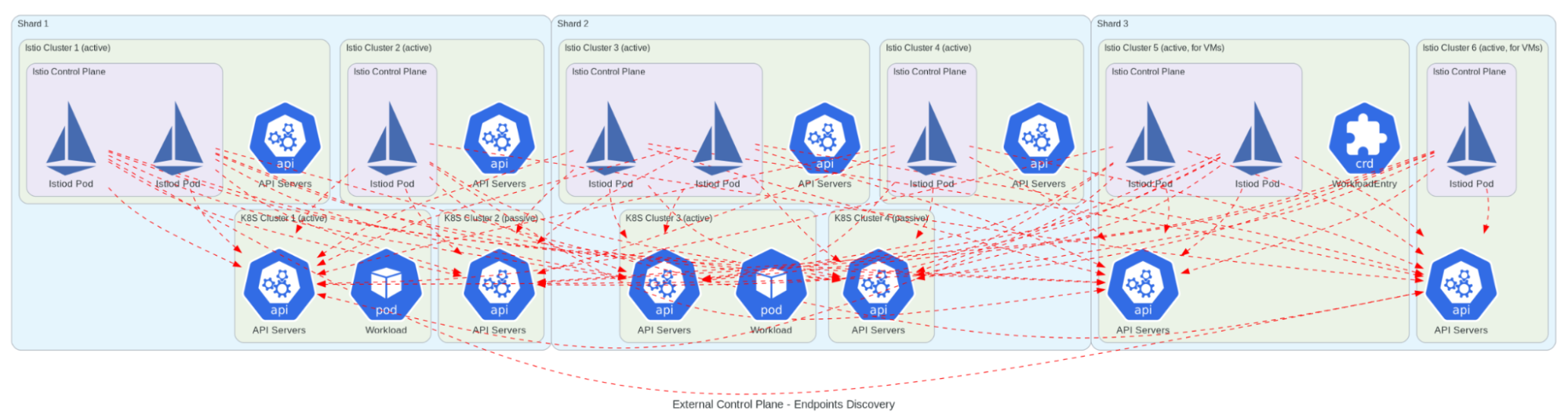
TechDocs at Grab: Cultivating a culture of quality documentation

Post Syndicated from Grab Tech original https://engineering.grab.com/techdocs-at-grab-cultivating-a-culture-of-quality-documentation

Introduction

Changing how a company approaches writing and documentation is a complex task. It’s not just about the tools and processes—it’s about shifting the mindset of the people who create and use documentation. Building a strong documentation culture means ensuring everyone takes ownership of producing high-quality content, while making the tools easy to use for everyone involved.

At Grab, our first significant step was adopting the Docs-as-Code approach, which we’ve covered in the blog Embracing a Docs-as-Code approach. This method integrated documentation into the engineering workflow, allowing teams to create and update content effortlessly.

Since then, the TechDocs working group — a collaboration between Tech Learning and the internal development team — has focused not just on improving tools, but on fostering a mindset where documentation is an essential part of everyday work. In this post, let us dive into how we’ve continued to embed high-quality documentation into the core of Grab’s engineering culture.

What is TechDocs?

Helix is Grab’s engineering platform designed to unify infrastructure, tooling, services, and documentation into a single, consistent user interface. It serves as a central hub for managing various engineering tasks and resources within Grab. Helix provides a comprehensive set of guides and tools for users.

TechDocs is an internal documentation platform built on Helix and integrates with our Docs-as-Code approach. It allows engineering teams to create, manage, and access technical content seamlessly within their workflows. TechDocs makes it easier for teams to maintain up-to-date, high-quality documentation with customised features for notification and editing.

How to create a healthy documentation culture

Over a span of 2 to 3 years, the TechDocs team executed these key steps in quarterly chunks to influence Grab’s documentation culture as seen in figure 1.

Figure 1: Key steps in influencing documentation culture in Grab
  1. Take inventory: Assess current internal processes, tools, and user behaviour.
  2. Finalise policy: Establish a clear policy, enforce it, and iterate based on feedback.
  3. Empower teams: Equip creators and maintainers with tools to manage their documentation.
  4. Track metrics, celebrate wins: Recognise and reward teams that follow best practices. Repeat regularly.

Now let’s look at each of these steps in detail.

Take inventory: Assess existing internal processes and tools/portals and understand user behaviour

Understanding the current culture

To shift the documentation culture at a company, you need to first understand what that culture is. At Grab, with its diverse business units, tech teams, and varied documentation practices, just grasping this was a big step. We needed to look at it from two angles: how teams and business units approach documentation, and what portals hold what kinds of resources.

Here are a few observations that apply not just to Grab but to most tech companies:

  • People default to the easiest way to get information, either by asking someone or searching familiar places. If they can’t find a document quickly, they assume it doesn’t exist.
  • Different teams use different documentation tools, leading to scattered, hard-to-maintain content. Without a unified search, finding the right document is a challenge.
  • Documentation is often created during development but rarely maintained, resulting in outdated or duplicate content over time.
  • Lack of clear ownership and governance causes inconsistencies, making it harder to trust or rely on documentation.

Conducting extensive user research

The insights on understanding the culture of documentation were obtained from conducting extensive feedback-gathering activities. We adopted two separate strategies for user research:

  1. The first focused on gathering feedback from as many people as possible. We scaled this approach to reach a wide audience across multiple teams and departments. To manage this volume, we used closed-ended questions with multiple-choice options, allowing us to collect broad, organisation-wide insights on user needs and preferences.
  2. The second approach was more in-depth and personal. We conducted 1:1 sessions where we observed how users interacted with tools, asked open-ended questions, and dug into the reasons behind their behaviors. This helped us understand not just what users did, but why and how they did it.

From the first approach, we were able to gather that users frequently browse for Runbooks, how-to’s, and FAQs when it comes to technical documentation. They emphasise structure, ease of navigation, and up-to-date content when it comes to quality.

Based on the feedback, only 2% of engineers (1 out of 56) reported that 80-100% of on-call engineering questions were resolved using technical documentation. In contrast, 29% of engineers indicated that 40-60% of their questions were addressed through documentation, while 25% stated that 20-40% were resolved in this manner.

To improve the documentation and Docs-as-Code workflows for seamless integration of documentation into the engineering process, we built the TechDocs Editor on the Helix platform. This rich text editor allowed teams to write and maintain their documents more effectively. However, while many engineers appreciated the new features, they highlighted areas for improvement for a smoother experience. Key suggestions included enhancing the creation of merge requests (MRs), resolving conflicts more efficiently, and offering an auto-approval process. They also wanted a way to preview content before MR approval, capabilities like bulk migration, and integration options such as plugins for Jira and *Confluence wiki. Additionally, there was a call to increase clarity on what content should belong in TechDocs versus the Wiki.

Rooting TechDocs tool’s improvements in the user’s feedback

Based on the feedback received from the extensive user research, the TechDocs tool’s new features were planned and lined up based on a priority mapping that was entirely rooted in the feedback from user research and interviews. While not all feedback was directly implementable in terms of tool improvements, a significant amount was. For issues that couldn’t be resolved through tools, cultural changes and learning best practices became key to addressing the challenges.

Here are insights from the 1-1 user research that helped us enhance the TechDocs tools and processes:

  • Search experience is average. The search experience on the TechDocs portal has room for improvement, with a CSAT score of 58.57%. Some users prefer using a more centralised search option, as it searches across multiple platforms and offers more relevant results, especially considering gaps in documentation on the internal TechDocs portal.
  • Documentation landing page needs improvement. The Documentation landing page scored 10.71% CSAT, highlighting its need for better design and categorisation. Users found the page cluttered, and the categorisation was seen as random and confusing.
  • Reading experience is positive. Overall, users are satisfied with reading documentation on Helix, with an 88.31% CSAT for reading experience. Users appreciated the navigation’s organisation and structure. Suggestions for further improvement include:

    • Better table content display
    • Maximising content space
    • Enhancing color contrast
  • TechDocs adoption still faces challenges. Although TechDocs adoption has grown, several challenges remain:
    • Migration efforts: The migration process requires significant effort, and without support or a clear push, some employees do not see the need to migrate.
    • Cultural factors: Users continue using familiar platforms and are looking for incentives, such as unique Helix features, to consider making the move.
    • Accessibility: VPN access is required for some features.
    • Awareness: Many users are unaware of Helix TechDocs’ full range of features, such as the different search options, available search filters, and commenting capabilities.
  • Cross-team collaboration challenges: Users reported difficulties in collaborating with non-engineering roles. While engineers are comfortable with the Docs-as-Code approach, which allows for more flexibility and simplicity, some find the TechDocs editor useful for initial document creation or small edits.

Using this feedback, the product roadmap was set for the year to focus on addressing the top user complaints and improving the TechDocs tools accordingly.

Finalise a suitable policy and begin enforcing it. Collect feedback and reiterate

To improve discoverability and maintain consistency, we established a structured policy for organising documents. This policy ensures that documentation is stored in the right place based on its purpose and usage, making it easier for Grabbers to find what they need. The key guidelines are as follows:

  • Markdown for ‘create and publish’ type content: Documentation related to platforms, products, or services that don’t require frequent updates should be in markdown format and stored in GitLab. These documents were rendered in Helix.
  • Collaborative portals for collaborative docs: Time-sensitive and collaborative documents—such as postmortems, RFCs, design docs, and project plans— are not compatible with docs-as-code and hence should reside in portals that offer collaboration features, like easy commenting and multi-user editing. Dedicated spaces within Confluence Wiki are ideal for this purpose.
  • Separation of internal data: Internal documents meant only for specific teams should not mix with general engineering resources for end users. These can be stored in portals with less stringent review processes, as they don’t require the same level of quality or accuracy checks. Team-specific spaces on Confluence Wiki can serve this need effectively.

Empower creators and maintainers to self-serve documentation upkeep

More documentation doesn’t mean good documentation

Getting people to create documentation is one thing, but getting them to maintain and update it is a whole different challenge. One major issue is the lack of accountability. Without a clear owning team or point of contact (PIC) for a document, everyone assumes someone else will handle updates. This leads to stale, outdated information because no one takes responsibility. To address this, the TechDocs team introduced features like showing the “last updated” date on each page and flagging documents that hadn’t been updated in over three months. This approach helped in two ways:

  • Readers could quickly gauge how up-to-date the information was.
  • Content owners were reminded when their documents needed attention.

Another key strategy was requiring every document to have a dedicated PIC at the time of creation. This ensured:

  • Clear accountability for maintaining the document.
  • The PIC would receive notifications about outdated documents and any comments from readers, making it easier to address issues.

What about docs that are not really meant to be updated that frequently?

When building any feature, it’s important to consider different use cases. While flagging outdated documents helped maintainers keep track of their content, it could also frustrate those responsible for more static documents that don’t require frequent updates.

To make the “last updated” feature more relevant, we introduced an option for users to mark documents as “verified.” This allowed maintainers to turn off the “your doc is outdated” flag if they felt the information was still accurate. While this feature could be misused in an extremely large organisation, it worked well at Grab where internal products and employees generally rely on mutual trust and respect for maintaining simple systems and policies.

Training and info-typing workshops

The TechDocs team had a unique advantage in influencing the quality of internal product and platform documentation. Many of the creators and maintainers of these documents belonged to the same organisation, which allowed for smoother collaboration.

To elevate the quality of TechDocs, we recognised that improving the drafts produced by platform engineers was essential. This realisation led us to create self-paced training materials focused on information typing guidelines and writing best practices specifically designed for these engineers, which included:

  • Info-typing guidelines: Helping engineers categorise information for better clarity.
  • Writing best practices: Teaching techniques to enhance readability and engagement.

Building on the positive feedback from the training course, we launched interactive workshops. In these sessions, participants brought their own team’s user-facing documentation, and with the guidance of expert Tech Content Developers (TCDs), they made significant, live updates to their documents using the info-typing principles they had learned. This process enabled participants to:

  • Revise their documents: Make real-time improvements during the workshop.
  • Receive expert feedback: Gain insights from TCDs on enhancing document quality.

The workshops received outstanding feedback and were further refined to cater to the specific needs of each team, ensuring that the training remained relevant and effective for the different documentation sets they managed. By focusing on collaboration and practical learning, we were able to foster a culture of continuous improvement in our documentation practices.

Track metrics, celebrate wins. Recognise and repeat.

Recognising teams and individuals who follow best practices is key to sustaining momentum. We celebrated these wins by publicly acknowledging contributions in newsletters and internal communications, along with offering swag and rewards. Additionally, we tracked the accuracy of responses from oncall-bots, which use documentation to auto-respond to user queries on our internal communicator. By analysing whether these automated responses were accurate, we could assess the quality of the docs being referenced. Teams that kept their documentation up-to-date and adhered to our internal TechDocs policy were rewarded, further reinforcing these good practices.

Celebrating wins wasn’t a one-off—it became a regular practice, helping to solidify desired behaviors and create a cycle of continuous improvement.

What’s next

Looking ahead, we have some exciting goals to push the documentation culture even further:

  • Boost documentation quality: We’re aiming to improve the quality of platform docs by a significant percentage, which will help reduce support tickets and inquiries to the automated tech support bot.
  • Expand training: We’re ramping up training for more engineers, helping them sharpen their tech writing skills and aiming for top CSAT ratings.
  • Launch improved TechDocs portal: Our goal is to build better and more intuitive navigation and categorisation of content for an improved user experience.
  • User interviews and engagement: We’ll be working closely with champions and users across tech families to create an open feedback loop.
  • Enhance doc creation and editing workflows: We’ll streamline the process of creating and editing content using templates and native tools with consistent Markdown flavour usage.

Join us

Grab is a leading superapp in Southeast Asia, operating across the deliveries, mobility and digital financial services sectors. Serving over 800 cities in eight Southeast Asian countries, Grab enables millions of people everyday to order food or groceries, send packages, hail a ride or taxi, pay for online purchases or access services such as lending and insurance, all through a single app. Grab was founded in 2012 with the mission to drive Southeast Asia forward by creating economic empowerment for everyone. Grab strives to serve a triple bottom line – we aim to simultaneously deliver financial performance for our shareholders and have a positive social impact, which includes economic empowerment for millions of people in the region, while mitigating our environmental footprint.

Powered by technology and driven by heart, our mission is to drive Southeast Asia forward by creating economic empowerment for everyone. If this mission speaks to you, join our team today!
Grab AI Gateway: Connecting Grabbers to Multiple GenAI Providers

Post Syndicated from Grab Tech original https://engineering.grab.com/grab-ai-gateway

The transformative world of Generative AI (GenAI), which refers to artificial intelligence systems capable of creating new content such as text, images, or music that is similar to human-generated content, has become integral to innovation, powering the next generation of AI-enabled applications. At Grab, it is crucial that every Grabber has access to these cutting-edge technologies to build powerful applications to better serve our customers and enhance their experiences. Grab’s AI Gateway aims to provide exactly this. The gateway seamlessly integrates AI providers like OpenAI, Azure, AWS (Bedrock), Google (VertexAI) and many other AI models, to bring seamless access to advanced AI technologies to every Grabber.

Why do we need Grab AI Gateway?

Before we begin implementing Grab AI Gateway in our work process, it is important for us to understand the limitations as well as the solutions that Grab AI Gateway provides. Failure to properly implement Grab AI Gateway could lead to roadblocks in development which negatively affect user experience.

Streamline access

Each AI provider has its own way of authenticating their services. Some providers use key-based authentication while others require instance roles or cloud credentials. Grab AI Gateway provides a centralised platform that only requires a one-time provider access setup. Grab AI Gateway removes the effort of procuring resources and setting up infrastructure for AI services, such as servers, storage, and other necessary components.

Enables experimentation

By providing a simple unified way to access different AI providers, users can experiment with various Large Language Models (LLMs) and choose the one best suited for their task.

Cost-efficient usage

Many AI providers allow purchasing of reserved capacity to provide higher throughput and improve cost effectiveness. However, services that require reservation or pre-purchases over a commitment period can lead to wastage.

Grab AI Gateway overcomes this problem and minimises wastage with a shared capacity pool. A deprecated service would simply free up bandwidth for a new service to utilise. Additionally, Grab AI Gateway provides a global view of usage trends to help platform teams make informed decisions on reallocating reserved capacity according to demand and future trends (eg. an upcoming model replacing an old one).

Auditing

A central setup ensures that use cases undergo a thorough review process to comply with the privacy and cyber security standards before being deployed in production. For instance, a Q&A bot with access to both restricted and non-restricted data could inadvertently reveal sensitive information if authorisation is not set up properly. Therefore, it is important that use cases are reviewed to ensure they follow Grab’s standard for data privacy and protection.

Platformisation benefits

Proper implementation of a central gateway provides platformisation benefits like:

  • Reduced operational costs.
  • Centralised monitoring and alerts.
  • Cost attribution.
  • Control limits like maximum QPS and cost cap.
  • Enforce guardrail and safety from prompt injection.

Architecture and design

At its core, the AI Gateway is a set of reverse proxies to different external AI providers like Azure, OpenAI, AWS, and others. From the user’s perspective, the AI Gateway acts like the actual provider where users are only required to set the correct base URLs to access the LLMs. The gateway handles functionalities like authentication, authorisation, and rate limiting, allowing users to solely focus on building GenAI enabled applications.

To form the basis of identity and access management (IAM) in the gateway, API key can be requested by the user for exploration (short-term personal key) or production (long-term service key) usage. The gateway implements a request path based authorisation where certain keys can be granted access to specific providers or features. Once authenticated, the AI Gateway replaces the internal key in request with the provider key and executes the request on behalf of the user.

The AI Gateway is designed with a minimalist approach, often serving as a lightweight interface between the user and the provider, intervening only when necessary. This has enabled us to keep up with the pace of innovation in the field and to continue expanding the provider catalogue without increasing the ops burden. Similar to requests, responses from the provider are returned to the user with no to minimal processing time. The gateway is not limited to only chat completion API. It exposes other APIs like embedding, image generation, and audio along with functionalities like fine-tuning, file storage, search, and context caching. The gateway also provides access to in-house open source models. This provides a taste of open source software (OSS) capabilities that users can later decide to deploy a dedicated instance using Catwalk’s VLLM offering.

Figure 1: High level architecture of AI Gateway

User journey and features

Onboarding process

GenAI based applications come with inherent risks like generating offensive or incorrect output and hostile takeover by malicious actors. As software practices and security standards for building GenAI applications are still evolving, it is important for users to be aware of the potential pitfalls. As AI Gateway is the de facto way to access this technology, the platform team shares the responsibility of building such awareness and ensuring compliance. The onboarding process includes a manual review stage. Every new use case requires a mini-RFC (Request For Comments) and a checklist that is reviewed by the platform team. In certain cases, an in-depth review by the AI Governance task force may be requested. To reduce friction, users are encouraged to build prototypes and experiment with APIs using “exploration keys”.

Exploration keys

At Grab, every Grabber is encouraged to use GenAI technologies to improve productivity and to experiment and learn within this field. The gateway provides exploration keys to make it easier for users to experiment with building chatbots and Retrieval Augmented Generation (RAG). These keys can be requested by Grabbers through a Slack bot. The keys are short-lived with a validity period of a few days, stricter rate limit restrictions, and access limited to only the staging environment. Exploration keys are highly popular, with more than 3,000 Grabbers requesting the key to experiment with APIs.

Unified API interface

In addition to provider specific interface, the gateway also offers a single interface to interact with multiple AI providers. For users, this lowers the barrier of experimenting between different providers/models, as they do not need to learn and rewrite their logic for different SDKs. Providers can be switched simply by changing the “model” parameter in the API request. This also enables easy setup of fallback logic and dynamic routing across providers. Based on popularity, the gateway uses the OpenAI API scheme to provide the unified interface experience. The API handler translates the request payload to the provider specific input scheme. The translated payload is then sent to reverse proxies. The returned response is translated back to the OpenAI response scheme.

Figure 2: Unified Interface Logic

Dynamic routing

The AI Gateway plays a crucial role in maintaining usage efficiency of various reserved instance capacities. It provides the control points to dynamically route requests for certain models to a different albeit similar model backed by a reserved instance. Another frequent use case is smart load balancing across different regions to address region-specific constraints related to maximum available quotas. This approach has helped to minimise rate limiting.

Auditing

The AI Gateway records each call’s request, response body, and additional metadata like token usage, URL path, and model name into Grab’s data lake. The purpose of doing so is to maintain a trail of usage which can be used for auditing. The archived data can be inspected for security threats like prompt injection or potential data policy violations.

Cost attribution

Allocating costs to each use case is important to encourage responsible usage. The cost of calling LLMs tends to increase at higher request rates, therefore understanding the incurred cost is crucial to understanding the feasibility of a use case. The gateway performs cost calculations for each request once the response is received from the provider. The cost is archived in the data lake along with an audit trail. For async usages like fine-tuning and assisting, the cost is calculated through a separate daily job. Finally, a job aggregates the cost for each service which is used for reporting on dashboards and showback. In addition, alerts are configured to notify if a service exceeds the cost threshold.

Rate limits

AI Gateway enforces its own rate limit on top of the global provider limits to make sure quotas are not consumed by a single service. Currently, limits are enforced on the request rate at the key level.

Integration with the ML Platform

At Grab, the ML platform serves as a one-stop shop, facilitating each phase of the model development lifecycle. The AI Gateway is well integrated with systems like Chimera notebooks used for ideation/development to Catwalk for deployment. When a user spins up a Chimera notebook, an exploration key is automatically mounted and is ready for use. For model deployments, users can configure the gateway integration which sets up the required environment variables and mounts the key into the app.

Challenges faced

With more than 300 unique use cases onboarded and many of those making it to production, AI Gateway has gained popularity since its inception in 2023. The gateway has come a long way, with many refinements made to the UX and provider offerings. The journey has not been without its challenges. Some of the challenges have become more prominent as the number of apps deployed increases.

Keeping up with innovations

With new features or LLMs being released at a rapid pace, the AI Gateway development has required continuous dedicated effort. Reflecting on our experience, it is easy to get overwhelmed by a constant stream of user requests for each new development in the field. However, we have come to realise it is important to balance release timelines and user expectations.

Fair distribution of quota

Every use case has a different service level objective (SLO). Batch use cases require high throughput but can tolerate failures while online applications are sensitive to latency and rate limits. In many cases, the underlying provider resource is the same. The responsibility falls over to the gateway to ensure fair distribution based on criticality and requests per second (RPS) requirements. As adoption increases, we have encountered issues where batch usage interfered with the uptime of online services. The use of Async APIs does mitigate the issues, but not all use cases can adhere to turnaround time.

Maintaining reverse proxies

Building the gateway as a reverse proxy was a key design decision. While the decision has proven to be beneficial, it is not without its complexity. The design ensures that the gateway is compatible with provider-specific SDKs. However, over time, we have encountered edge cases where certain SDK functionalities do not work as expected due to a missing path in the gateway or a missing configuration. These issues are usually ironed out when caught and a suite of integration tests with SDKs are conducted to ensure there are no breaking changes before deploying.

Current use cases and applications

Today, the gateway powers many AI-enabled applications. Some examples include real time audio signal analysis for enhancing ride safety, content moderation to block unsafe content, and description generator for menu items and many others.

Internally, the gateway powers innovative solutions to boost productivity and reduce toil. A few examples are:

  • GenAI portal that is used for translation and language detection tasks, image generation, and file analysis.
  • Text-to-Insights for converting questions into SQL queries.
  • Incident management automation for triaging incidents and creating reports.
  • Support bot for answering user queries in Slack channels using a knowledge base.

What’s next?

As we continue to add more features, we plan to focus our efforts on these areas:

1. Catalogue

With over 50 AI models each suited for a specific task type, finding the correct model to use is becoming complex. Users are often unsure of the difference between models in terms of capabilities, latency, and cost implications. A catalogue can serve as a guideline by listing currently supported models along with the list of metadata like the input/output modality, token limits, provider quota, pricing, and reference guide.

2. Out of box governance

Currently, all AI-enabled services that process clear text input and output from customers require users to set up their own guardrails and safety measures. By creating a built-in support for security threats like prompt injection and guardrails for filtering input/output, we can save users significant effort.

3. Smarter rate limits

At the current time, the gateway supports basic request rate-based limits at key level. While this rudimentary offering has been proven useful, it has its limitations. More advanced rate limiting policies based on token usage or daily/monthly running costs should be introduced to enforce better and fairer limits. These policies can be modified to be applied on different models and providers.

Special thanks to Priscilla Lee, Isella Lim, and Kevin Littlejohn for helping us in the project and Padarn Wilson for his leadership.

Join us

Grab is the leading superapp platform in Southeast Asia, providing everyday services that matter to consumers. More than just a ride-hailing and food delivery app, Grab offers a wide range of on-demand services in the region, including mobility, food, package and grocery delivery services, mobile payments, and financial services across 700 cities in eight countries.

Powered by technology and driven by heart, our mission is to drive Southeast Asia forward by creating economic empowerment for everyone. If this mission speaks to you, join our team today!