Tag Archives: Uncategorized

Friday Squid Blogging: Video of Giant Squid Hunting Prey

Post Syndicated from Bruce Schneier original https://www.schneier.com/blog/archives/2021/06/friday-squid-blogging-video-of-giant-squid-hunting-prey.html

Fantastic video of a giant squid hunting at depths between 1,827 and 3,117 feet.

This is a follow-on from this post.

As usual, you can also use this squid post to talk about the security stories in the news that I haven’t covered.

Read my blog posting guidelines here.

Getting started with serverless for developers part 5: Sandbox developer account

Post Syndicated from Benjamin Smith original https://aws.amazon.com/blogs/compute/getting-started-with-serverless-for-developers-part-5-sandbox-developer-account/

This is part 5 of the Getting started with serverless series. In part 4, you learn how the developer workflow for building serverless applications differs to a traditional developer workflow. You see how to test business logic locally before deploying to an AWS account.

In this post, you learn how to secure and manage access to your AWS Lambda functions. I show how to invoke Lambda functions in a sandbox developer account directly from an integrated developer environment (IDE) and view output logs in near-real-time. Finally, I show how this helps to test for infrastructure and security configurations before committing changes to the main branch.

A sandbox developer account

Serverless services like Lambda and Amazon API Gateway are pay-per-use, this means developers no longer need to share multiple environments (for example, dev, staging, and production). Instead, every developer can have their own sandboxed AWS developer account. This allows developers to not have to replicate everything to their local environment but rather test with real resources in the cloud.

You can still run code locally during the development of a feature. In post 4, I show how I run Lambda function code locally, using a test harness. This allows me to maintain a fast inner loop, iteratively updating and locally testing code. If my Lambda function interacts with other AWS infrastructure, I deploy them to a sandboxed AWS developer account. This allows me to test my Lambda function code locally while still being able to access managed services in the cloud.

However, it is useful to deploy your function code to a Lambda function in a sandboxed developer account. A sandbox developer account is an AWS account allocated to a developer on a 1:1 basis. It should give developers as much freedom as possible while still protecting resources and budget.

This allows you to test for security configurations and ensure that your Lambda function code behaves as expected when run in the Lambda execution environment:

Creating a sandboxed developer account

The following best practices can help to minimize costs and prevent unauthorized usage.

After creating a sandbox account, it can be useful to associate a named profile with it. A named profile is a collection of credentials that you can apply to an AWS Command Line Interface (AWS CLI) command. When you specify a profile to run a command, the settings and credentials are used to run that command. The AWS CLI supports multiple named profiles that are stored in the config and credentials files.

Configure profiles by adding entries to the config and credentials files. To learn more about named profiles refer to the AWS CLI documentation.

In the following example I configure my credentials file with two named profiles.

The profile named prod is my production account, and the profile named default is my sandbox developer account. The CLI automatically uses the profile named default, if no --profile option is specified in a CLI command.

[default]
aws_access_key_id=AKIAIOSFODNN7EXAMPLE
aws_secret_access_key=wJalrXUtnFEMI/K7MDENG/bPxRfiCYEXAMPLEKEY

[dev]
aws_access_key_id=AKIAIOSFODNN7EXAMPLE
aws_secret_access_key=wJalBBUtnFEMI/&7MDENG/bPxRfiCYEXAMPLEKEY

[prod]
aws_access_key_id=AKIAI44QH8DHBEXAMPLE
aws_secret_access_key=je7MtGbClwBF/2Zp9Utk/h3yCo8nvbEXAMPLEKEY

AWS Lambda security permissions

AWS Identity and Access Management (IAM) is the service used to manage access to AWS services. Lambda is fully integrated with IAM, allowing you to control precisely what each Lambda function can do within the AWS Cloud. There are two important things that define the scope of permissions in Lambda functions:

The resource policy: Defines which events are authorized to invoke the function.

The execution role policy: Limits what the Lambda function is authorized to do.

Using IAM roles to describe a Lambda function’s permissions, decouples it’s security configuration from the code. This helps reduce the complexity of a lambda function, making it easier to maintain.

A Lambda function’s resource and execution policy should be granted the minimum required permissions for the function to perform it’s task effectively. This is sometimes referred to as the rule of least privilege. As you develop a Lambda function, you expand the scope of this policy to allow access to other resources as required.

When building Lambda-based applications with frameworks such as AWS SAM, you describe both policies in the application’s template.

The following steps show how I deploy and test a Lambda function in a sandbox developer account from within my IDE.

Before you start

All the code relating to this example application can be found in this GitHub repository. To deploy this stage of the application, follow the steps from post 1 to clone the sample application.

  1. Run the following command from the root directory of the cloned repository:
    cd ./part_5
  2. After creating a sandbox developer account, deploy the example application into it by specifying the corresponding profile name in the AWS SAM CLI command. You can omit this if you named the profile default:
    sam deploy --config-file ../samconfig.toml  –guided  --profile default

    This produces the following output:

    Make a note of the StarWebhookLambdaFunctionName, you will use this in the following steps.

Logging with serverless applications

After deploying your serverless application to the sandboxed developer account, you need to verify that it’s operating properly. Lambda automatically monitors functions on your behalf, reporting metrics through Amazon CloudWatch. It collects data in the form of logs, metrics, and events and provides a unified view of AWS resources, applications, and services.

To help simplify troubleshooting, the AWS Serverless Application Model CLI (AWS SAM CLI) has a command called sam logs. This command lets you fetch CloudWatch Logs generated by your Lambda function from the command line.

Run the following command in a terminal window to view a live tail of logs generated by the StarWebhookHandler Lambda function. Replace StarWebhookLambdaFunctionName with the Lambda function name generated by your deployment:

sam logs -n StarWebhookLambdaFunctionName --tail

Checking Lambda function permissions in a sandbox developer account

I open a new terminal window and invoke the StarWebhookHandler Lambda function directly from my IDE by running the following AWS SAM CLI command. To invoke the function I pass an example payload located in events/testEvent.json.

aws lambda invoke --function-name <<replace-with-function-name>> \
--payload fileb://events/testEvent.json  \
out.txt

The following screenshot shows my two terminal windows side by side.

The response returned by the CLI command is on the right. The left window shows the tail of logs generated by the Lambda function. I observe that the CLI invocation shows a status 200 response, but the Lambda function logs report an ‘AccessDenied’ error. The function does not have the required permissions to write to Amazon S3.

I edit the Lambda function policy definition, adding permission for my Lambda function to write to an S3 bucket. I run sam build and sam deploy to re-deploy the application to the sandbox developer account. I invoke the Lambda function again. The logs show the following:

  1. The Lambda function responds with “StatusCode 200″.
  2. The Lambda function billed duration, memory size and running duration.
  3. The Lambda function has successfully copied the file to S3

IAM permission errors such as these may not be detected when running the function code locally. This is one of the advantages of deploying and running Lambda functions in a sandboxed developer account while developing an application.

Conclusion

This post explains the advantages of using a sandbox developer account. It shows how to deploy your business logic to a Lambda function in a sandboxed developer account. You are introduced to IAM policies, which control precisely what each Lambda function can do within the AWS Cloud. You learn that CloudWatch provides a unified view of logs for all AWS resources.

Finally, I show how to use the AWS SAM CLI and AWS CLI to invoke a Lambda function in the cloud and view its log output directly from the IDE. This helps to test for security configurations and to ensure that your business logic behaves as expected when run in the Lambda service. Invoking functions and observing their log output directly from your IDE helps to reduce context switching as you build.

Getting Started with serverless for developers: Part 4 – Local developer workflow

Post Syndicated from Benjamin Smith original https://aws.amazon.com/blogs/compute/getting-started-with-serverless-for-developers-part-4-local-developer-workflow/

This blog is part 4 of the “Getting started with serverless for developers” series, helping developers start building serverless applications from their IDE.

Many “getting started” guides demonstrate how to build serverless applications from within the AWS Management Console. However, most developers spend the majority of their time building from within their local integrated development environment (IDE).

The next two blog posts in this series focus on the serverless developer workflow. They describe how to check logs, test, and iterate on business logic while building locally, and how this differs from traditional applications.

This blog post explains how the developer workflow for building serverless applications differs from a traditional developer workflow. It shows the methods that I use to test business logic locally before deploying to a sandbox AWS developer account, and how to test against cloud services as you build. This eliminates the need to deploy to the AWS Cloud each time you want to test a code change.

Traditional developer workflow

Developers typically use the following workflow cycle before committing code to the main branch:

  1. Write code.
  2. Save code.
  3. Run code.
  4. Check results.

This is sometimes referred to as the inner loop, shown as follows:

With traditional (non-serverless) applications, developers commonly create a development environment on their local machine. This local development environment keeps parity with the staging and production environments. It allows developers to test their application locally end-to-end before committing code to the main branch.

Serverless developer workflow

Part 2: the business logic, explains how serverless applications use managed services that abstract away the need for developers to patch and scale their application infrastructure. This means that the code base in a serverless application is focused purely on business logic, allowing managed services to handle other important layers such as:

  • Authorization
  • Presentation
  • Database
  • Application integration
  • Notification

A good serverless developer workflow enables developers to test and iterate on business logic quickly. It allows them to check that the business logic runs correctly with the managed services that compose an application.

To achieve this, the best approach is not to try and emulate managed services on your local development machine. Instead, your local code should interact directly with real cloud services in a sandboxed AWS account.

This approach lets you rapidly test and iterate on business logic locally, deploying to the development environment to test for infrastructure, security, and environment configuration changes. Once the business logic is ready in the development environment, it can be deployed to other environments (test, staging, production) via CI/CD automation or manually triggered commands.

The following sections explain how I test business logic locally using a custom-written test harness. Each time I create a Lambda function I create a directory to hold:

  1. The function code.
  2. A relative package.json.
  3. A file called testharness.js.

The test harness file is used to run the Lambda function code on my local development machine. It is configured to mock environment variables loaded from a file named `env.json` and loads a JSON test event payload located in the events directory.

Testing Lambda function code locally with a test harness

Part 2: the business logic, explains the anatomy of a Lambda function and its handler:

A small Lambda function

Note that the function handler receives an input payload called an event object. To test the local function code effectively, use a test event object that represents the production event object.

The serverless application introduced in getting started with serverless part 1, shows that Amazon API Gateway invokes the Lambda function.

This invocation contains an event object with a JSON representation of the HTTP request. The event object has a defined structure. Follow the steps in this GitHub repository to see how to create a test event object.

Before you start

To deploy this stage of the application, follow the steps from post 1 to clone and deploy the sample application.

  1. Run the following commands from the root directory of the cloned repository:
    cd ./part_4/src_starred
    npm install

The following steps show how I configure my testharness.js file to run my function code:

// Mock event
const event = require('../events/testEvent.json')
// Mock environment variables
const environmentVars = require('../env.json')
process.env.AWS_REGION = environmentVars.AWS_REGION
process.env.localTest = true
process.env.slackEndpoint= environmentVars.slackEndpoint
process.env.bucket = environmentVars.bucket
// Lambda handler
const { handler } = require('./app')
const main = async () => {
  console.time('localTest')
  console.dir(await handler(event))
  console.timeEnd('localTest')
}
main().catch(error => console.error(error))
  1. A test event object is loaded into a variable called event.
  2. The environment variables required by the Lambda function are defined in env.json and loaded.
  3. The Lambda function code is loaded into a variable called handler
  4. The Lambda function code is run synchronously
  5. The console shows output from the Lambda function code, along with any errors that occur.

I run my test harness file by entering the following command in a terminal window:

$ node testharness.js

This produces the following output:

The output indicates that the function code ran without error, it returned a 200 status code and completed in 30.999 ms.

To generate an error in the function code,  I change the app.js file by commenting out the following line:

//const axios = require('axios');

I save the file and run the test harness again. I see the following response in the terminal window:

f

This indicates an error in my function code that I must resolve before deploying to my AWS account.

By iteratively updating and locally testing my code, I maintain a fast inner loop. This eliminates the need to deploy to the AWS Cloud each time I want to test a code change.

Testing against cloud resources

In many instances, a Lambda function interacts with other cloud resources. This could be via an SDK or some other native integration. In this case, you should deploy those resources to a sandboxed AWS developer account.

In the following example, I update a Lambda function to log each inbound HTTP request to a bucket in Amazon S3, a highly scalable object storage service running in the AWS cloud. To do this, I use the JavaScript SDK:

s3.putObject(params, function(err, data)

I update the AWS Serverless Application Model (AWS SAM) template to define a new S3 bucket:

SrcBucket:
Type: AWS::S3::Bucket

I change into the part_4 directory then build and deploy the application with the following commands:

cd ../part_4
sam build
sam deploy --guided --config-file ../samconfig.toml

After deploying, the output shows:

I copy the new bucket value to the environment variable defined in in /part_4/env.json .

"slackEndpoint": "Insert_Slack_Endpoint",
"bucket" : "Insert_S3_Bucket_Name"
}

Now I am ready to test the local Lambda function code against cloud resources in my sandbox AWS development account. I run a new local test with the following command:

node testHarness.js

The terminal returns:

This indicates that the Lambda function code completed without error. I can verify this by checking the contents of the S3 bucket using the AWS Command Line Interface (AWS CLI):

aws s3 ls s3://githubtoslackapp-srcbucket-ge4wkt9dljwa

This returns the following, confirming that the request object has been saved to S3 and the application code is running correctly:

Conclusion

Using managed services to build serverless applications helps developers focus on business logic. It also changes the developer workflow compared with building traditional (non-serverless) applications.

A good serverless developer workflow enables developers to test and iterate on business logic quickly while still being able to interact with cloud services. This blog post shows how I achieve this by using a test harness to run function code locally and deploying application resources to a sandboxed developer account.

In the next blog post, I show how to invoke Lambda functions deployed to sandboxed developer account, without leaving your IDE. This lets you test for infrastructure, security, and environment configuration changes while building.

CDK Corner – May 2021

Post Syndicated from Christian Weber original https://aws.amazon.com/blogs/devops/cdk-corner-may-2021/

Social – community engagement

According to Matt Coulter’s tweet, nearly 4000 people signed up for CDK Day to celebrate all things CDK on April 30. As a single-day, two-track event, there was a significant amount of content to learn from while having fun, and interacting with the CDK community.

Eric Johnson as the emcee, keynoted the first session of the morning, presenting “Better together: AWS CDK and AWS SAM.” This keynote was the announcement for the public preview of the AWS Serverless Application Model CLI (AWS SAM CLI). The AWS Serverless Application Model CLI includes support for local development and testing of AWS CDK projects.

To learn more, the blog post announcing the AWS SAM CLI public preview has more detail about the capabilities of the AWS SAM CLI.

If you missed CDK Day, fear not! CDK Day Track 1 and Track2 are available to watch online.

Great job and round of applause to the sign-language translators, the speakers, the organizers, and the hosts for making the second CDK Day a success! We can’t wait for CDK Day number 3!

Updates to the CDK

AWS CDK v2 developer preview

It’s here! The much-anticipated release of CDK v2’s developer preview is now available!

When using CDK previously, developers in JavaScript and TypeScript have faced challenges with the way that npm handles transitive dependencies; the dependencies that your dependencies rely on. For example, the aws-ec2 package.json file lists dependencies for other CDK construct libraries. If one of these transitive dependencies were updated, all of them would be need to be updated. Or you would run into dependency tree resolution errors, as seen in this StackOverflow thread.

With v2, all construct modules are now provided in a single package: aws-cdk-lib. All of the dependencies are now pinned to a single version of aws-cdk-lib, making it easier to manage. This also gives you the flexibility of having all CDK construct library modules available without having to run npm install each time you want to use a new construct library.

Another change to AWS CDK v2 is the removal of experimental modules. To help promote API stability and comply with semantic versioning, CDK v2 ships only with modules marked as stable.

Experimental modules aren’t going away completely, though. In v1, experimental modules and constructs will be provided together with no change. In v2, experimental modules are distributed and versioned separately from the aws-cdk-lib package, in their own dedicated package and namespace. Once a v2 construct is deemed stable, it is then merged into the aws-cdk-lib package.

The CDK team is still determining the best method of distributing experimental modules and constructs, so stay tuned for more information. Read more about the AWS CDK v2 developer preview in the What’s new blog post.

AWS CDK for Go developer preview

On April 7, the AWS CDK team announced support for golang. From the Go tracking issue on GitHub, nearly 900 members of the CDK community have requested for CDK to support golang, and we’re happy to see it become available! We are looking forward to helping out all the golang gophers out there build amazing CDK applications!

To learn more about Go and AWS CDK, read the AWS CDK for Go module API documentation on pkg.go.dev. You can also read the Go bindings for JSII RFC document on GitHub. Want to contribute to the success of Go and CDK? The project tracking board for Go’s General Availability has tasks and items which could use your help.

Construct modules promoted to General Availability

Many new construct modules were promoted to General Availability recently. General Availability indicates a module’s stability, giving confidence to run these modules in production workloads. In April, a total of 15 modules were promoted stable:

Notable new L2 constructs

In the @aws-cdk/route-53 module, name server (NS) records were previously defined with the route53.RecordType enum. In PR#13895, user stijnbrouwers introduces the NS record as its own L2 construct: route53.NSRecord. bringing it into company with other record type L2s, such as route53.ARecord. This makes managing NS records consistent with the other record types represented as L2 constructs.

Improving the @aws-cdk/aws-events-targets module, CDK community user hedrall submitted PR#13823. This change brings support for Amazon API Gateway as a target for an Amazon EventBridge event.

@aws-cdk/aws-codepipeline-actions now includes an L2 construct for AWS CodeStar Connections supporting BitBucket and GitHub. This construct lets you create a CDK application that uses AWS CodeStar with a source connection from either provider, thanks to PR#13781 from the CDK Team.

Level ups to existing CDK constructs

Amazon Elastic Inference makes available low-cost GPU-acceleration for deep-learning workloads. PR#13950 now lets you use the service via @aws-cdk/aws-ecs in Amazon Elastic Container Service tasks, from CDK community user upparekh.

In PR#13473, from pgarbe, the @aws-cdk/aws-lambda-nodejs module will now bundle AWS Lambda functions with Docker images sourced from the Amazon Elastic Container Registry (Amazon ECR) Public Registry, instead of DockerHub. Prior to this change, CDK used your DockerHub credentials to pull a Docker image for the Lambda function. If your account was in DockerHub’s free-tier account level, your account is throttled whenever it exceeds the API limit within a short time frame set by DockerHub. This can cause your AWS CDK deployment to be delayed until you are under DockerHub’s API limit. By moving to the Amazon ECR Public Registry, this removes the risk of being affected by DockerHub’s API rate limiting . You can read more in this blog post giving customers advice about DockerHub rate limits from last year.

With @aws-cdk/aws-codebuild, you can use concurrent build support to speed up your build process. Sometimes you’ll want to limit the number of builds that run concurrently, whether for cost reduction or reducing the complexity of your build process. PR#14185, authored by gmokki, adds the ability to define a concurrent build limit for an AWS CodeBuild project Stage.

It is common for customers to have applications or resources spanning multiple AWS Regions. If you’re using @aws-cdk/aws-secretsmanager, you can now replicate secrets to multiple Regions, with PR#14266 from the CDK team. Make sure you’re not setting your secret as “test123” for your production databases in multiple Regions!

For users of @aws-cdk/aws-eks, PR#12659 from anguslees lets you pass arguments from bootstrap.sh to avoid the DescribeCluster API call. This will speed up the time it takes nodes to join an EKS cluster.

PR#14250 from the CDK team gives developers using @aws-cdk/aws-ec2 the ability to set fixed IPs when defining NAT gateways. This change will now pre-create Elastic IP address allocations and assign them to the NAT gateway. This can be useful when managing links from an Amazon Virtual Private Cloud (VPC) to an on-premises data center that relies on fixed/static IP addresses.

@aws-cdk/aws-iam now lets you add AWS Identity and Access Management (AWS IAM) users to new or existing groups. For example, you might want to have a user in a specific group for the life of a deployed CDK application. And on stack deletion, revoke that membership. Thanks to PR#13698 from jogold, this is now possible.

Learning – Finds from across the internet

If you work with CDK parameters, you might be curious how parameters derive their names and values. Borislav Hadzhiev released a blog post about setting and using CDK parameters.

Ibrahim Cesar’s wrote an awesome blog post detailing the experience of discovering and working with CDK. It’s an enjoyable read of inspiration and animated gifs.

Twitter user edwin4_ released a tool for CDK automation called RocketCDK. From the project’s GitHub repository, this tool will initialize your CDK app, install your packages, and auto-import them into your stack. Neat! Anything that helps save time is a plus-one.

Community acknowledgments

And finally, congratulations and rounds of applause for these folks who had their first Pull Request merged to the CDK repository!

*These users’ Pull Requests were merged in April.

Thank you for joining us on this update of the CDK corner. See you next time!

In the Works – AWS Region in the United Arab Emirates (UAE)

Post Syndicated from Jeff Barr original https://aws.amazon.com/blogs/aws/in-the-works-aws-region-in-the-united-arab-emirates-uae/

We are currently building AWS regions in Australia, Indonesia, Spain, India, and Switzerland.

UAE in the Works
I am happy to announce that the AWS Middle East (UAE) Region is in the works and will open in the first half of 2022. The new region is an extension of our existing investment, which already includes two AWS Direct Connect locations and two Amazon CloudFront edge locations, all of which have been in place since 2018. The new region will give AWS customers in the UAE the ability to run workloads and to store data that must remain in-country, in addition to the ability to serve local customers with even lower latency.

The new region will have three Availability Zones, and will be the second AWS Region in the Middle East, joining the existing AWS Region in Bahrain. There are 80 Availability Zones within 25 AWS Regions in operation today, with 15 more Availability Zones and five announced regions underway in the locations that I listed earlier.

As is always the case with an AWS Region, each of the Availability Zones will be a fully isolated part of the AWS infrastructure. The AZs in this region will be connected together via high-bandwidth, low-latency network connections to support applications that need synchronous replication between AZs for availability or redundancy.

AWS in the UAE
In addition to the upcoming AWS Region and the Direct Connect and CloudFront edge locations, we continue to build our team of account managers, partner managers, data center technicians, systems engineers, solutions architects, professional service providers, and more (check out our current positions).

We also plan to continue our on-going investments in education initiatives, training, and start-up enablement to support the UAE’s plans for economic development and digital transformation.

Our customers in the UAE are already using AWS to drive innovation! For example:

Mohammed Bin Rashid Space Centre (MBRSC) – Founded in 2006, MBSRC is home to the UAE’s National Space Program. The Hope Probe was launched last year and reached Mars in February of this year. Data from the probe’s instruments is processed and analyzed on AWS, and made available to the global scientific community in less than 20 minutes.

Anghami is the leading music platform in the Middle East and North Africa, giving over 70 million users access to 57 million songs. They have been hosting their infrastructure on AWS since their days as a tiny startup,. and have benefited from the ability to scale up by as much as 300% when new music is launched.

Sarwa is an investment bank and personal finance platform that was born on the AWS cloud in 2017. They grew by a factor of four in 2020 while processing hundreds of thousands of transactions. Recent AWS-powered innovations from Sarwa include the Sarwa App (design to market in 3 months) and the upcoming Sarwa Trade platform.

Stay Tuned
We’ll be announcing the opening of the Middle East (UAE) Region in a forthcoming blog post, so be sure to stay tuned!

Jeff;

Build and Deploy Docker Images to AWS using EC2 Image Builder

Post Syndicated from Joseph Keating original https://aws.amazon.com/blogs/devops/build-and-deploy-docker-images-to-aws-using-ec2-image-builder/

The NFL, an AWS Professional Services partner, is collaborating with NFL’s Player Health and Safety team to build the Digital Athlete Program. The Digital Athlete Program is working to drive progress in the prevention, diagnosis, and treatment of injuries; enhance medical protocols; and further improve the way football is taught and played. The NFL, in conjunction with AWS Professional Services, delivered an EC2 Image Builder pipeline for automating the production of Docker images. Following similar practices from the Digital Athlete Program, this post demonstrates how to deploy an automated Image Builder pipeline.

“AWS Professional Services faced unique environment constraints, but was able to deliver a modular pipeline solution leveraging EC2 Image Builder. The framework serves as a foundation to create hardened images for future use cases. The team also provided documentation and knowledge transfer sessions to ensure our team was set up to successfully manage the solution.”—Joseph Steinke, Director, Data Solutions Architect, National Football League

A common scenario you may face is how to build Docker images that can be utilized throughout your organization. You may already have existing processes that you’re looking to modernize. You may be looking for a streamlined, managed approach so you can reduce the overhead of operating your own workflows. Additionally, if you’re new to containers, you may be seeking an end-to-end process you can use to deploy containerized workloads. With either case, there is need for a modern, streamlined approach to centralize the configuration and distribution of Docker images. This post demonstrates how to build a secure end-to-end workflow for building secure Docker images.

Image Builder now offers a managed service for building Docker images. With Image Builder, you can automatically produce new up-to-date container images and publish them to specified Amazon Elastic Container Registry (Amazon ECR) repositories after running stipulated tests. You don’t need to worry about the underlying infrastructure. Instead, you can focus simply on your container configuration and use the AWS tools to manage and distribute your images. In this post, we walk through the process of building a Docker image and deploying the image to Amazon ECR, share some security best practices, and demonstrate deploying a Docker image to Amazon Elastic Container Service (Amazon ECS). Additionally, we dive deep into building Docker images following modern principles.

The project we create in this post addresses a use case in which an organization needs an automated workflow for building, distributing, and deploying Docker images. With Image Builder, we build and deploy Docker images and test our image locally that we have created with our Image Builder pipeline.


Solution Overview

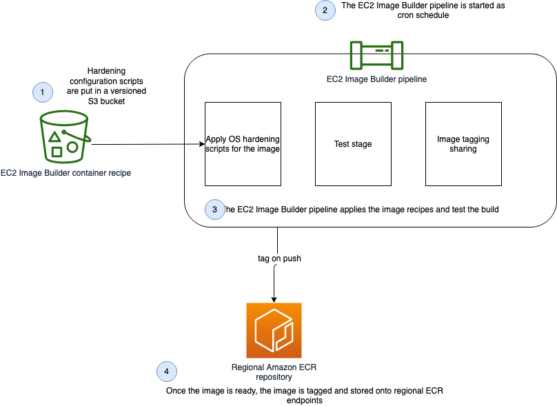
The following diagram illustrates our solution architecture.

Show the architecture of the Docker EC2 Image Builder Pipeline

Figure: Show the architecture of the Docker EC2 Image Builder Pipeline


We configure the Image Builder pipeline with AWS CloudFormation. Then we use Amazon Simple Storage Service (Amazon S3) as our source for the pipeline. This means that when we want to update the pipeline with a new Dockerfile, we have to update the source S3 bucket. The pipeline assumes an AWS Identity and Access Management (IAM) role that we generate later in the post. When the pipeline is run, it pulls the latest Dockerfile configuration from Amazon S3, builds a Docker image, and deploys the image to Amazon ECR. Finally, we use AWS Copilot to deploy our Docker image to Amazon ECS. For more information about Copilot, see Applications.

The style in which the Dockerfile application code was written is a personal preference. For more information, see Best practices for writing Dockerfiles.


Overview of AWS services

For this post, we use the following services:

  • EC2 Image BuilderImage Builder is a fully managed AWS service that makes it easy to automate the creation, management, and deployment of customized, secure, and up-to-date server images that are pre-installed and pre-configured with software and settings to meet specific IT standards.
  • Amazon ECRAmazon ECR is an AWS managed container image registry service that is secure, scalable, and reliable.
  • CodeCommit – AWS CodeCommit is a fully-managed source control service that hosts secure Git-based repositories.
  • AWS KMS – Amazon Key Management Service (AWS KMS) is a fully managed service for creating and managing cryptographic keys. These keys are natively integrated with most AWS services. You use a KMS key in this post to encrypt resources.
  • Amazon S3Amazon Simple Storage Service (Amazon S3) is an object storage service utilized for storing and encrypting data. We use Amazon S3 to store our configuration files.
  • AWS CloudFormation – AWS CloudFormation allows you to use domain-specific languages or simple text files to model and provision, in an automated and secure manner, all the resources needed for your applications across all Regions and accounts. You can deploy AWS resources in a safe, repeatable manner, and automate the provisioning of infrastructure.


Prerequisites

To provision the pipeline deployment, you must have the following prerequisites:


CloudFormation templates

You use the following CloudFormation templates to deploy several resources:

  • vpc.yml – Contains all the core networking configuration. It deploys the VPC, two private subnets, two public subnets, and the route tables. The private subnets utilize a NAT gateway to communicate to the internet. The public subnets have full outbound access to the internet gateway.
  • kms.yml – Contains the AWS Key Management Service (AWS KMS) configuration that we use for encrypting resources. The KMS key policy is also configured in this template.
  • s3-iam-config.yml – Contains the S3 bucket and IAM roles we use with our Image Builder pipeline.
  • docker-image-builder.yml – Contains the configuration for the Image Builder pipeline that we use to build Docker images.


Docker Overview

Containerizing an application comes with many benefits. By containerizing an application, the application is decoupled from the underlying infrastructure, greater consistency is gained across environments, and the application can now be deployed in a loosely coupled microservice model. The lightweight nature of containers enables teams to spend less time configuring their application and more time building features that create value for their customers. To achieve these great benefits, you need reliable resources to centralize the creation and distribution of your container images. Additionally, you need to understand container fundamentals. Let’s start by reviewing a Docker base image.

In this post, we follow the multi-stage pattern for building our Docker image. With this approach, we can selectively copy artifacts from one phase to another. This allows you to remove anything not critical to the application’s function in the final image. Let’s walk through some of the logic we put into our Docker image to optimize performance and security.

Let’s begin by looking at line 15-25. Here, we are pulling down the latest amazon/aws-cli Docker image. We are leveraging this image so that we can utilize IAM credentials to clone our CodeCommit repository. In lines 15-24 we are installing and configuring our git configuration. Finally, in line 25 we are cloning our application code from our repository.

In this next section, we set environment variables, installing packages, unpack tar files, and set up a custom Java Runtime Environment (JRE). Amazon Corretto is a no-cost, multi-platform, production-ready distribution of the Open Java Development Kit (OpenJDK). One important distinction to make here is how we are utilizing RUN and ADD in the Dockerfile. By configuring our own custom JRE we can remove unnecessary modules from our image. One of our goals with building Docker images is to keep them lightweight, which is why we are taking the extra steps to ensure that we don’t add any unnecessary configuration.

Let’s take a look at the next section of the Dockerfile. Now that we have all the package that we require, we will create a working directory where we will install our demo app. After the application code is pulled down from CodeCommit, we use Maven to build our artifact.

In the following code snippet, we use FROM to begin a new stage in our build. Notice that we are using the same base as our first stage. If objects on the disk/filesystem in in the first stage stay the same, the previous stage cache can be reused. Using this pattern can greatly reduce build time.

Docker images have a single unique digest. This is a SHA-256 value and is known as the immutable identifier for the image. When changes are made to your image, through a Dockerfile update for example, a new image with a new immutable identifier is generated. The immutable identifier is pinned to prevent unexpected behaviors in code due to change or update. You can also prevent man-in-the-middle attacks by adopting this pattern. Additionally, using a SHA can mitigate the risk of having to rely on mutable tags that can be applied or changed to the wrong image by mistake. You can use the following command to check to ensure that no unintended changes occured.

docker images <input_container_image_id> --digests

Lastly, we configure our final stage, in which we create a user and group to manage our application inside the container. As this user, we copy the binaries created from our first stage. With this pattern, you can clearly see the benefit of using stages when building Docker images. Finally, we note the port that should be published with expose for the container and we define our Entrypoint, which is the instruction we use to run our container.


Deploying the CloudFormation templates

To deploy your templates, complete the following steps:

1. Create a directory where we store all of our demo code by running the following from your terminal:

mkdir awsblogrepo && cd awsblogrepo


2. Clone the source code repository found in the following location:

git clone https://github.com/aws-samples/build-and-deploy-docker-images-to-aws-using-ec2-image-builder.git

You now use the AWS CLI to deploy the CloudFormation templates. Make sure to leave the CloudFormation template names as written in this post.


3. Deploy the VPC CloudFormation template:

aws cloudformation create-stack \
--stack-name vpc-config \
--template-body file://templates/vpc.yml \
--parameters file://parameters/vpc-params.json  \
--capabilities CAPABILITY_IAM \
--region us-east-1

The output should look like the following code:

{
    "StackId": "arn:aws:cloudformation:us-east-1:123456789012:stack/vpc-config/12e90fe0-76c9-11eb-9284-12717722e021"
}


4. Open the parameters/kms-params.json file and update the UserARN parameter with your account ID:

[
  {
      "ParameterKey": "KeyName",
      "ParameterValue": "DemoKey"
  },
  {
    "ParameterKey": "UserARN",
    "ParameterValue": "arn:aws:iam::<input_your_account_id>:root"
  }
]


5. Deploy the KMS key CloudFormation template:

aws cloudformation create-stack \
--stack-name kms-config \
--template-body file://templates/kms.yml \
--parameters file://parameters/kms-params.json \
--capabilities CAPABILITY_IAM \
--region us-east-1

The output should look like the following:

{
    "StackId": "arn:aws:cloudformation:us-east-1:123456789012:stack/kms-config/66a663d0-777d-11eb-ad2b-0e84b19d341f"
}


6. Open the parameters/s3-iam-config.json file and update the DemoConfigS3BucketName parameter to a unique name of your choosing:

[
  {
    "ParameterKey" : "Environment",
    "ParameterValue" : "dev"
  },
  {
    "ParameterKey": "NetworkStackName",
    "ParameterValue" : "vpc-config"
  },
  {
    "ParameterKey" : "EC2InstanceRoleName",
    "ParameterValue" : "EC2InstanceRole"
  },
  {
    "ParameterKey" : "DemoConfigS3BucketName",
    "ParameterValue" : "<input_your_unique_bucket_name>"
  },
  {
    "ParameterKey" : "KMSStackName",
    "ParameterValue" : "kms-config"
  }
]


7. Deploy the IAM role configuration template:

aws cloudformation create-stack \
--stack-name s3-iam-config \
--template-body file://templates/s3-iam-config.yml \
--parameters file://parameters/s3-iam-config.json \
--capabilities CAPABILITY_NAMED_IAM \
--region us-east-1

The output should look like the following:

{
    "StackId": "arn:aws:cloudformation:us-east-1:123456789012:stack/s3-iam-config/8b69c270-7782-11eb-a85c-0ead09d00613"
}


8. Open the parameters/kms-params.json file:

[
  {
      "ParameterKey": "KeyName",
      "ParameterValue": "DemoKey"
  },
  {
    "ParameterKey": "UserARN",
    "ParameterValue": "arn:aws:iam::1234567891012:root"
  }
]


9. Add the following values as a comma-separated list to the UserARN parameter key. Make sure to provide your AWS account ID:

arn:aws:iam::<input_your_aws_account_id>:role/EC2ImageBuilderRole

When finished, the file should look similar to the following:

[
  {
      "ParameterKey": "KeyName",
      "ParameterValue": "DemoKey"
  },
  {
    "ParameterKey": "UserARN",
    "ParameterValue": "arn:aws:iam::123456789012:role/EC2ImageBuilderRole,arn:aws:iam::123456789012:root"
  }
]

Now that the AWS KMS parameter file has been updated, you update the AWS KMS CloudFormation stack.


10. Run the following command to update the kms-config stack:

aws cloudformation update-stack \
--stack-name kms-config \
--template-body file://templates/kms.yml \
--parameters file://parameters/kms-params.json \
--capabilities CAPABILITY_IAM \
--region us-east-1

The output should look like the following:

{
    "StackId": "arn:aws:cloudformation:us-east-1:123456789012:stack/kms-config/66a663d0-777d-11eb-ad2b-0e84b19d341f"
}


11. Open the parameters/docker-image-builder-params.json file and update the ImageBuilderBucketName parameter to the bucket name you generated earlier:

[
  {
    "ParameterKey": "Environment",
    "ParameterValue": "dev"
  },
  {
      "ParameterKey": "ImageBuilderBucketName",
      "ParameterValue": "<input_your_s3_bucket_name>"
  },
  {
      "ParameterKey": "NetworkStackName",
      "ParameterValue": "vpc-config"
  },
  {
      "ParameterKey": "KMSStackName",
      "ParameterValue": "kms-config"
  },
  {
      "ParameterKey": "S3ConfigStackName",
      "ParameterValue": "s3-iam-config"
  },
  {
      "ParameterKey": "ECRName",
      "ParameterValue": "demo-ecr"
  }
]


12. Run the following commands to upload the Dockerfile and component file to S3. Make sure to update the s3 bucket name with the name you generated earlier:

aws s3 cp java/Dockerfile s3://<input_your_bucket_name>/Dockerfile && \
aws s3 cp components/component.yml s3://<input_your_bucket_name>/component.yml

The output should look like the following:

upload: java/Dockerfile to s3://demo12345/Dockerfile
upload: components/component.yml to s3://demo12345/component.yml


13. Deploy the docker-image-builder.yml template:

aws cloudformation create-stack \
--stack-name docker-image-builder-config \
--template-body file://templates/docker-image-builder.yml \
--parameters file://parameters/docker-image-builder-params.json \
--capabilities CAPABILITY_NAMED_IAM \
--region us-east-1

The output should look like the following:

{
    "StackId": "arn:aws:cloudformation:us-east-1:123456789012:stack/docker-image-builder/24317190-76f4-11eb-b879-0afa5528cb21"
}


Configure the Repository

You use AWS CodeCommit as your source control repository. You now walk through the steps of deploying our CodeCommit repository:


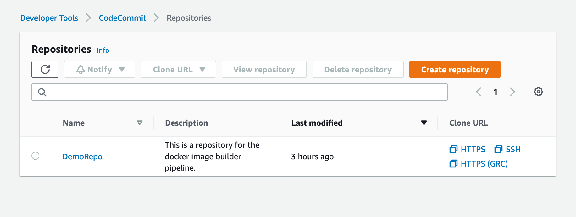
1. On the CodeCommit console, choose Repositories.


2. Locate your repository and under Clone URL, choose HTTPS.

Shows DemoRepo CodeCommit Repository

Figure: Shows DemoRepo CodeCommit Repository

You clone this repository in the build directory you created when deploying the CloudFormation templates.


3. In your terminal, past the Git URL from the previous step and clone the repository:

git clone https://git-codecommit.us-east-1.amazonaws.com/v1/repos/DemoRepo


4. Now let’s create and push your main branch:

cd DemoRepo
git checkout -b main
touch initial.txt
git add . && git commit -m "Initial commit"
git push -u origin main


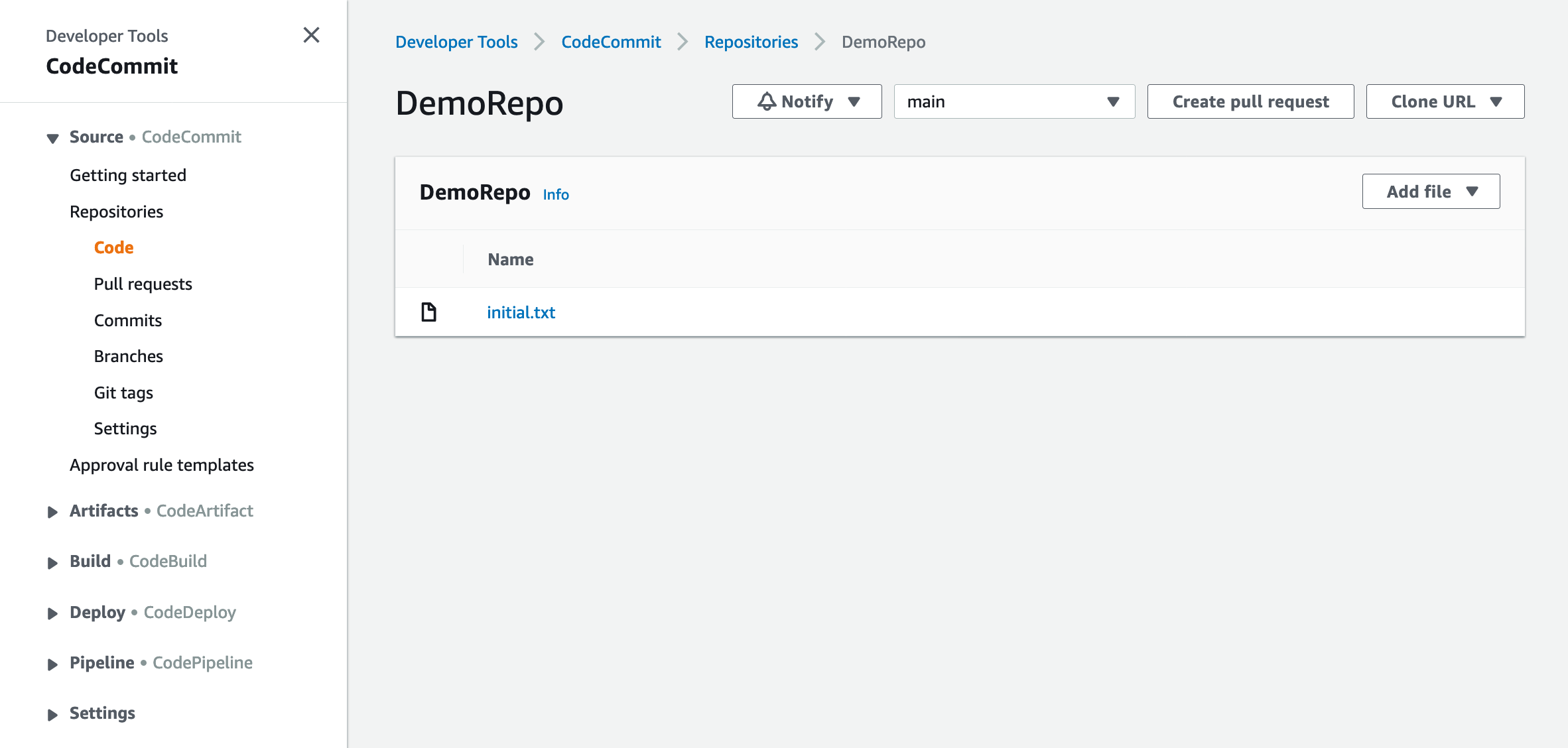
5. On the Repositories page of the CodeCommit console, choose DemoRepo.

The following screenshot shows that we have created our main branch and pushed our first commit to our repository.

Shows the DemoRepo main branch

Figure: Shows the DemoRepo main branch


6. Back in your terminal, create a new feature branch:

git checkout -b feature/configure-repo


7. Create the build directories:

mkdir templates; \
mkdir parameters; \
mkdir java; \
mkdir components

You now copy over the configuration files from the cloned GitHub repository to our CodeCommit repository.


8. Run the following command from the awsblogrepo directory you created earlier:

cp -r build-and-deploy-docker-images-to-aws-using-ec2-image-builder/* DemoRepo/


9. Commit and push your changes:

git add . && git commit -m "Copying config files into source control." 
git push --set-upstream origin feature/configure-repo


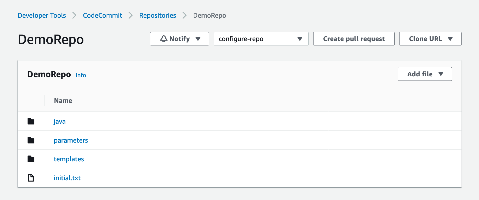
10. On the CodeCommit console, navigate to DemoRepo.

Shows the DemoRepo CodeCommit Repository

Figure: Shows the DemoRepo CodeCommit Repository


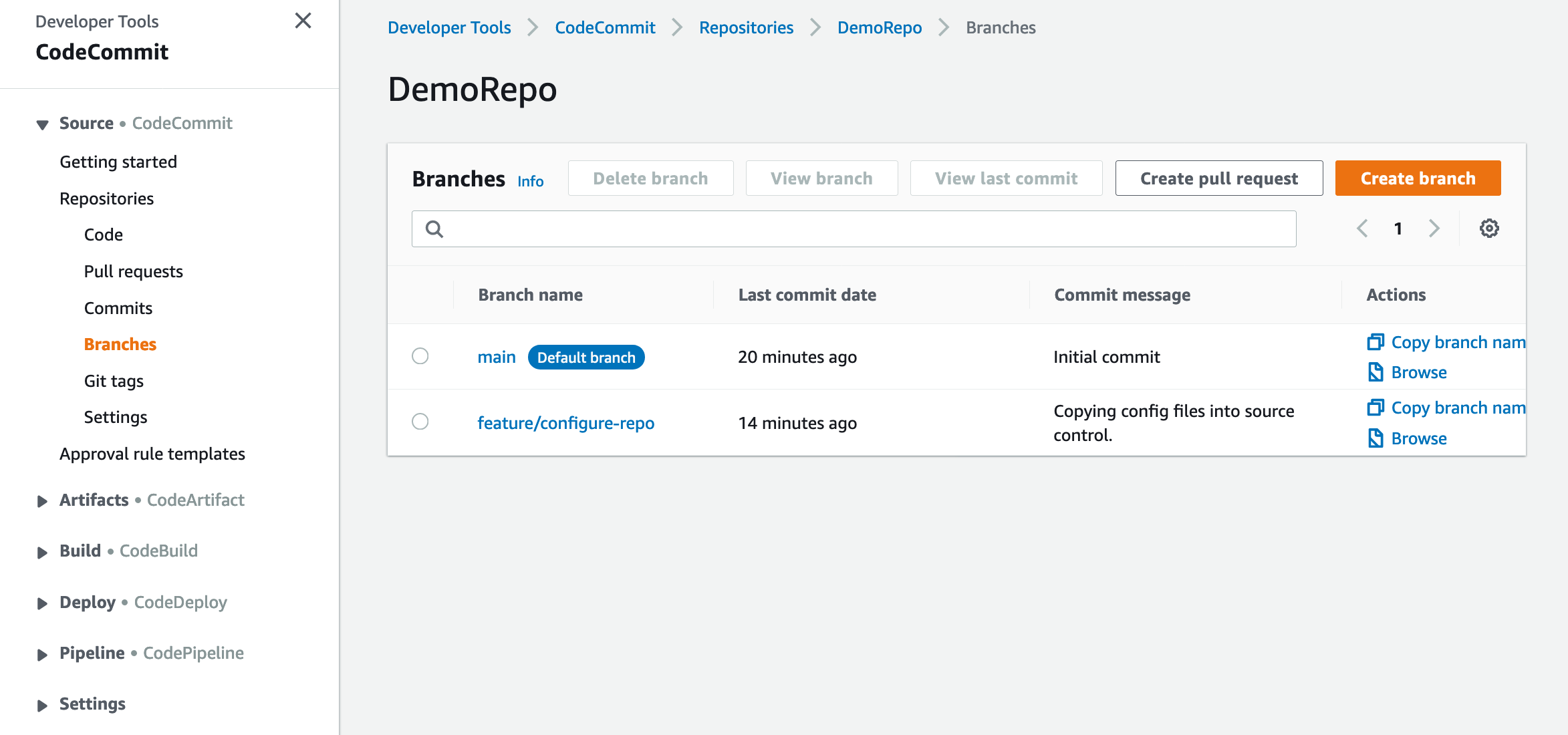
11. In the navigation pane, under Repositories, choose Branches.

Shows the DemoRepo's code

Figure: Shows the DemoRepo’s code


12. Select the feature/configure-repo branch.

Shows the DemoRepo's branches

Figure: Shows the DemoRepo’s branches


13. Choose Create pull request.

Shows the DemoRepo code

Figure: Shows the DemoRepo code


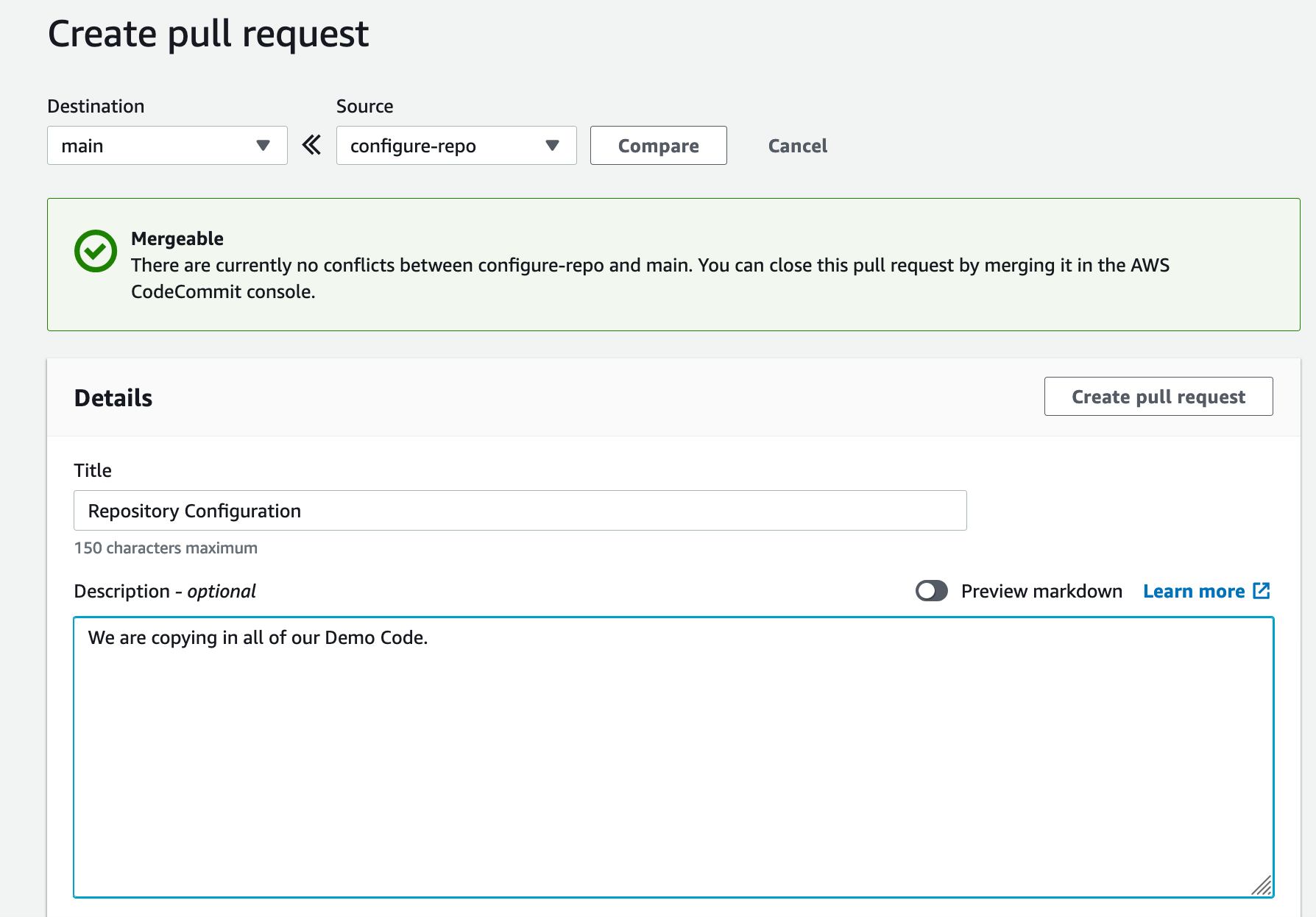
14. For Title, enter Repository Configuration.


15. For Description, enter a brief description.


16. Choose Create pull request.

Shows a pull request for DemoRepo

Figure: Shows a pull request for DemoRepo


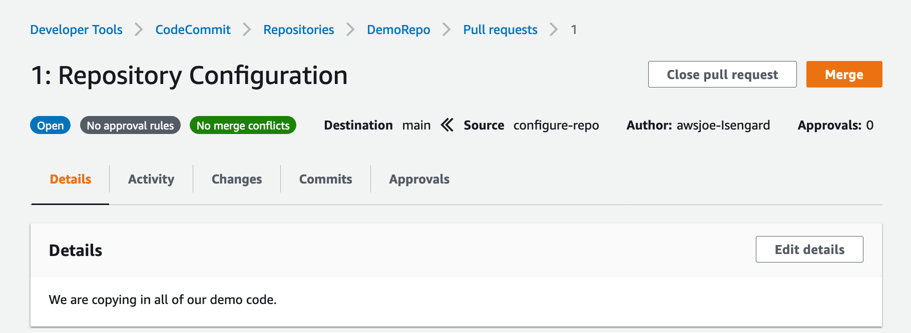
17. Choose Merge to merge the pull request.

Shows merge for DemoRepo pull request

Figure: Shows merge for DemoRepo pull request

Now that you have all the code copied into your CodeCommit repository, you now build an image using the Image Builder pipeline.


EC2 Image Builder Deep Dive

With Image Builder, you can build and deploy Docker images to your AWS account. Let’s look at how your Image Builder pipeline is configured.

A recipe defines the source image to use as your starting point to create a new image, along with the set of components that you add to customize your image and verify that everything is working as expected. Take note of the ParentImage property. Here, you’re declaring that the parent image that your pipeline pulls from the latest Amazon Linux image. This enables organizations to define images that they have approved to be utilized downstream by development teams. Having better control over what Docker images development teams are using improves an organization security posture while enabling the developers to have the tools they need readily available. The DockerfileTemplateUri property refers to the location of the Dockerfile that your Image Builder pipeline is deploying. Take some time to review the configuration.


Run the Image Builder Pipeline

Now you build a Docker image by running the pipeline.

1. Update your account ID and run the following command:

aws imagebuilder start-image-pipeline-execution \
--image-pipeline-arn arn:aws:imagebuilder:us-east-1:<input_your_aws_account_id>:image-pipeline/docker-image-builder-config-docker-java-container

The output should look like the following:

{
    "requestId": "87931a2e-cd74-44e9-9be1-948fec0776aa",
    "clientToken": "e0f710be-0776-43ea-a6d7-c10137a554bf",
    "imageBuildVersionArn": "arn:aws:imagebuilder:us-east-1:123456789012:image/docker-image-builder-config-container-recipe/1.0.0/1"
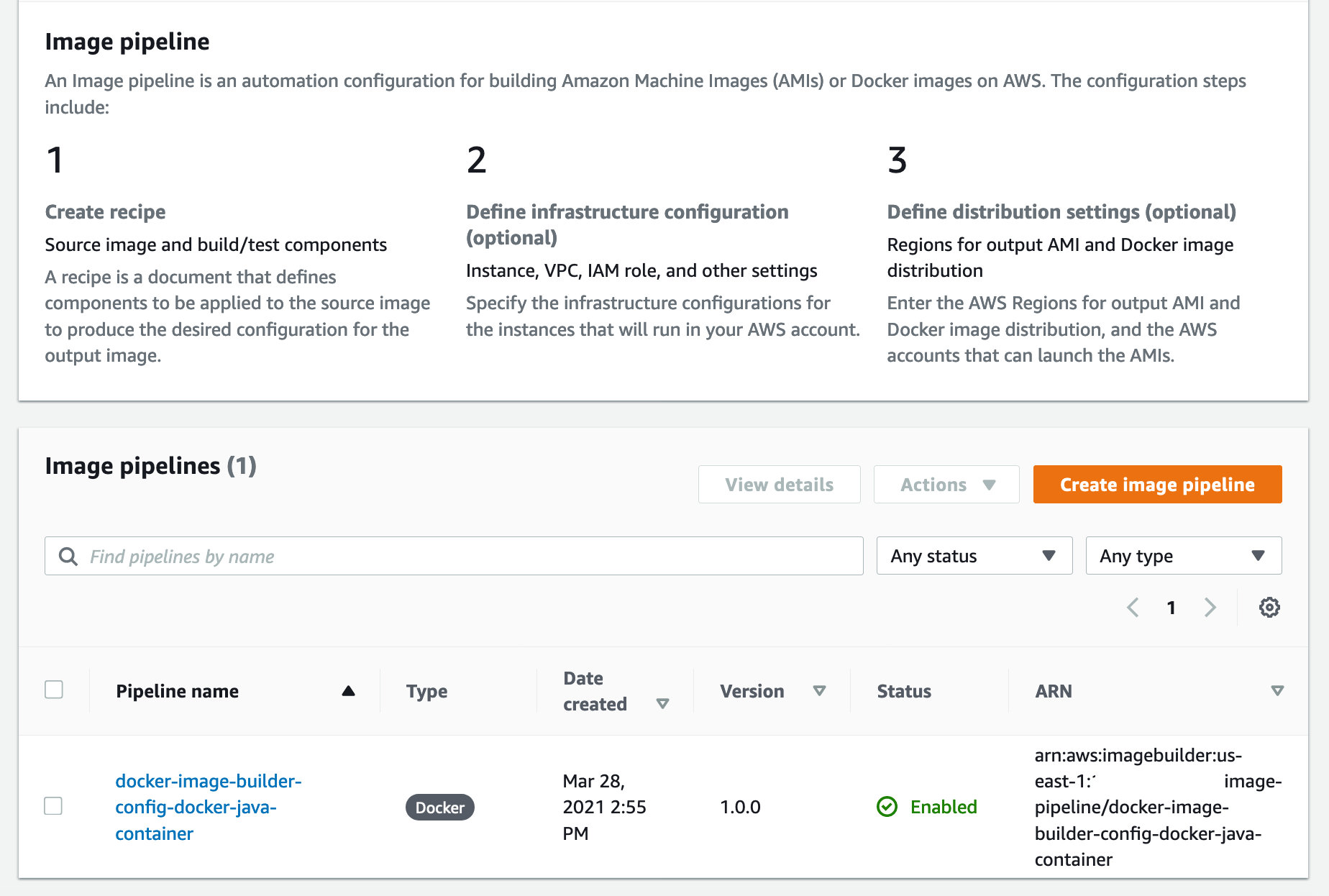
}


2. On the Image Builder console, choose the docker-image-builder-config-docker-java-container pipeline.

 Shows EC2 Image Builder Pipeline status

Figure: Shows EC2 Image Builder Pipeline status

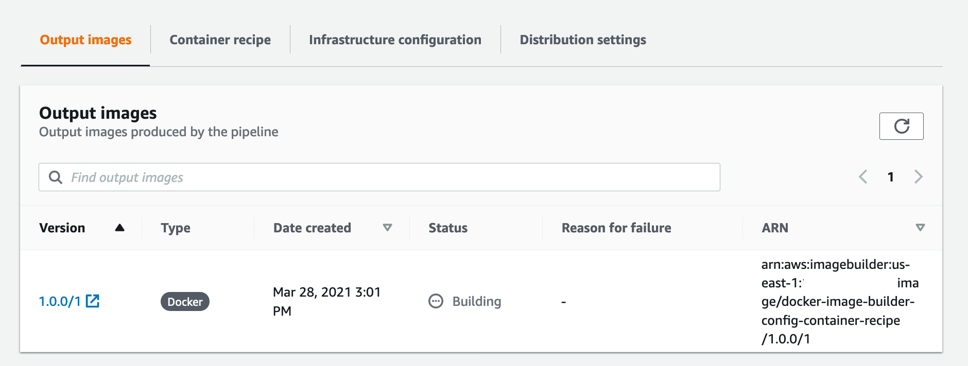
At the bottom of the page, a new Docker image is building.


3. Wait until the image status becomes Available.

Shows docker image building in EC2 Image Builder console

Figure: Shows docker image building in EC2 Image Builder console


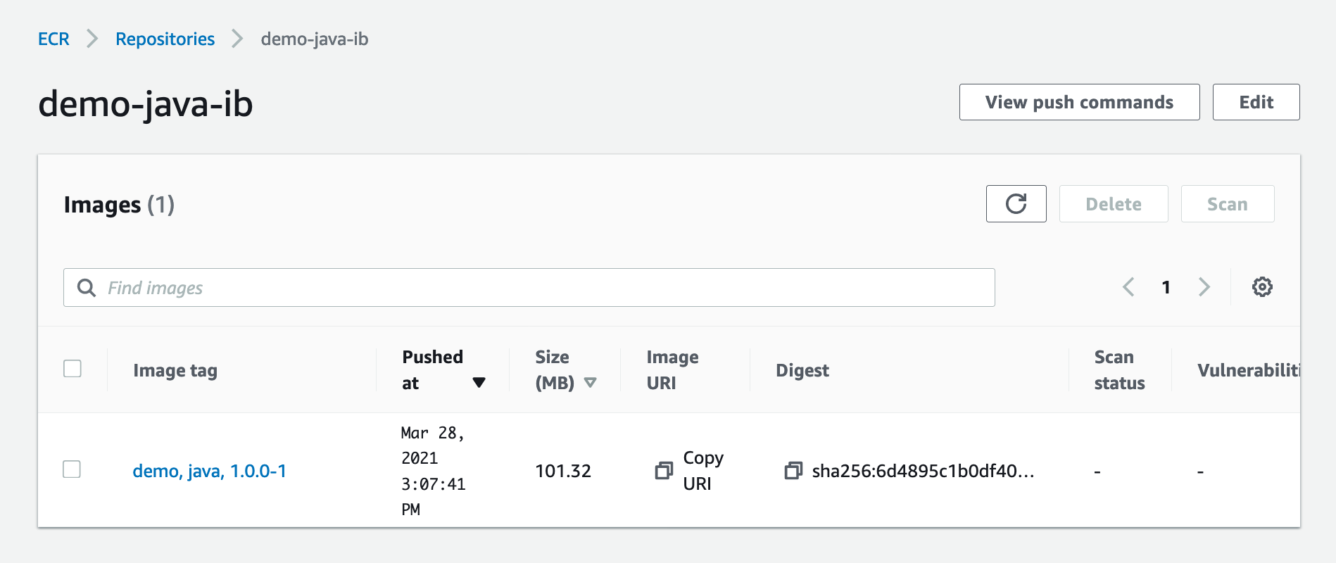
4. On the Amazon ECR console, open java-demo-ib.

The Docker image has been successfully created, tagged, and deployed to Amazon ECR from the Image Builder pipeline.

Shows demo-java-ib image in ECR

Figure: Shows demo-java-ib image in ECR


Test the Docker Image Locally

1. On the Amazon ECR console, open java-demo-ib.


2. Copy the image URI.

ECR Screenshot


3. Run the following commands to authenticate to your ECR repository:

aws ecr get-login-password --region us-east-1 | docker login --username AWS --password-stdin <input_your_account_id>.dkr.ecr.us-east-1.amazonaws.com


4. Run the following command in your terminal, and update the Amazon ECR URI with the content you copied from the previous step:

docker pull <input_ecr_image_uri>

You should see output similar to the following:

1.0.0-80: Pulling from demo-java-ib
596ba82af5aa: Pull complete 
6f476912a053: Pull complete 
3e7162a86ef8: Pull complete 
ec7d8bb8d044: Pull complete 
Digest: sha256:14668cda786aa496f406062ce07087d66a14a7022023091e9b953aae0bdf2634
Status: Downloaded newer image for 123456789012.dkr.ecr.us-east-1.amazonaws.com/demo-java-ib:1.0.0-1
123456789012.dkr.ecr.us-east-1.amazonaws.com/demo-java-ib:1.0.0-1


5. Run the following command from your terminal:

docker image ls

You should see output similar to the following:

REPOSITORY                                                  TAG        IMAGE ID       CREATED          SIZE
123456789012.dkr.ecr.us-east-1.amazonaws.com/demo-java-ib   1.0.0-1   ac75e982863c   34 minutes ago   47.3MB


6. Run the following command from your terminal using the IMAGE ID value from the previous output:

docker run -dp 8090:8090 --name java_hello_world -it <docker_image_id> sh

You should see an output similar to the following:

49ea3a278639252058b55ab80c71245d9f00a3e1933a8249d627ce18c3f59ab1


7. Test your container by running the following command:

curl localhost:8090

You should see an output similar to the following:

Hello World!


8. Now that you have verified that your container is working properly, you can stop your container. Run the following command from your terminal:

docker stop java_hello_world


Conclusion

In this article, we showed how to leverage AWS services to automate the creation, management, and distribution of Docker Images. We walked through how to configure EC2 Image Builder to create and distribute Docker images. Finally, we built a Docker image using our EC2 Image Builder pipeline and tested the image locally. Thank you for reading!


Joe Keating is a Modernization Architect in Professional Services at Amazon Web Services. He works with AWS customers to design and implement a variety of solutions in the AWS Cloud. Joe enjoys cooking with a glass or two of wine and achieving mediocrity on the golf course.


Virginia Chu is a Sr. Cloud Infrastructure Architect in Professional Services at Amazon Web Services. She works with enterprise-scale customers around the globe to design and implement a variety of solutions in the AWS Cloud.


BK works as a Senior Security Architect with AWS Professional Services. He love to solve security problems for his customers, and help them feel comfortable within AWS. Outside of work, BK loves to play computer games, and go on long drives.

Create a serverless feedback collector application using Amazon Pinpoint’s two-way SMS functionality

Post Syndicated from Murat Balkan original https://aws.amazon.com/blogs/messaging-and-targeting/create-a-serverless-feedback-collector-application-by-using-amazon-pinpoints-two-way-sms-functionality/

Introduction

Two-way SMS communication is used by many companies to create interactive engagements with their customers. Traditional SMS notifications are one-way. While this is valid for many different use cases like one-time passwords (OTP) notifications and security notifications or reminders, some other use-cases may benefit from collecting information from the same channel. Two-way SMS allows customers to create this feedback mechanism and enhance business interactions and overall customer experience.

SMS is chosen for its simplicity and availability across different sets of devices. By combining the two-way SMS mechanism with the vast breadth of services Amazon Web Services (AWS) offers, companies can create effective architectures to better interact and serve their customers.

This blog post shows you how a serverless online appointment application can use Amazon Pinpoint’s two-way SMS functionality to collect customer feedback for completed appointments. You will learn how Amazon Pinpoint interacts with other AWS serverless services with its out-of-the-box integrations to create a scalable messaging application.

Architecture

By completing the steps in this post, you can create a system that uses the architecture illustrated in the following image:

The architecture of a feedback collector application that is composed of serverless AWS services

The flow of events starts when a Amazon DynamoDB table item, representing an online appointment, changes its status to COMPLETED. An AWS Lambda function which is subscribed to these changes over DynamoDB Streams detects this change and sends an SMS to the customer by using Amazon Pinpoint API’s sendMessages operation.

Amazon Pinpoint delivers the SMS to the recipient and generates a unique message ID to the AWS Lambda function. The Lambda function then adds this message ID to a DynamoDB table called “message-lookup”. This table is used for tracking different feedback requests sent during a multi-step conversation and associate them with the appointment ids. At this stage, the Lambda function also populates another table “feedbacks” which will hold the feedback responses that will be sent as SMS reply messages.

Each time a recipient replies to an SMS, Amazon Pinpoint publishes this reply event to an Amazon SNS topic which is subscribed by an Amazon SQS queue. Amazon Pinpoint will also add a messageId to this event which allows you to bind it to a sendMessages operation call.

A second AWS Lambda function polls these reply events from the Amazon SQS queue. It checks whether the reply is in the correct format (i.e. a number) and also associated with a previous request. If all conditions are met, the AWS Lambda function checks the ConversationStage attribute’s value from its message-lookup table. According to the current stage and the SMS answer received, AWS Lambda function will determine the next step.

For example, if the feedback score received is less than 5, a follow-up SMS is sent to the user asking if they’ll be happy to receive a call from the customer support team.

All SMS replies from the users are reflected to “feedbacks” table for further analysis.

Deploying the Sample Application

  1. Clone this GitHub repository to your local machine and install and configure AWS SAM with a test AWS IAM user.

You will use AWS SAM to deploy the remaining parts of this serverless architecture.

The AWS SAM template creates the following resources:

    • An Amazon DynamoDB table (appointments) that contains information about appointments, customers and their appointment status.
    • An Amazon DynamoDB table (feedbacks) that holds the received feedbacks from customers.
    • An Amazon DynamoDB table (message-lookup) that holds the Amazon Pinpoint message ids and associate them to appointments to track a multi-step conversation.
    • Two AWS Lambda functions (FeedbackSender and FeedbackReceiver)
    • An Amazon SNS topic that collects state change events from Amazon Pinpoint.
    • An Amazon SQS queue that queues the incoming messages.
    • An Amazon Pinpoint Application with an associated SMS channel.

This architecture consists of two Lambda functions, which are represented as two different apps in the AWS SAM template. These functions are named FeedbackSender and FeedbackReceiver. The FeedbackSender function listens the Amazon DynamoDB Stream associated with the appointments table and sends the SMS message requesting a feedback. Second Lambda function, FeedbackReceiver, polls the Amazon SQS queue and updates the feedbacks table in Amazon DynamoDB. (pinpoint-two-way-sms)

          Note: You’ll incur some costs by deploying this stack into your account.

  1. To start the SAM deployment, navigate to the root directory of the repository you downloaded and where the template.yaml AWS SAM template resides. AWS SAM also requires you to specify an Amazon Simple Storage Service (Amazon S3) bucket to hold the deployment artifacts. If you haven’t already created a bucket for this purpose, create one now. The bucket should have read and write access by an AWS Identity and Access Management (IAM) user.

At the command line, enter the following command to package the application:

sam package --template template.yaml --output-template-file output_template.yaml --s3-bucket BUCKET_NAME_HERE

In the preceding command, replace BUCKET_NAME_HERE with the name of the Amazon S3 bucket that should hold the deployment artifacts.

AWS SAM packages the application and copies it into this Amazon S3 bucket.

When the AWS SAM package command finishes running, enter the following command to deploy the package:

sam deploy --template-file output_template.yaml --stack-name BlogStackPinpoint --capabilities CAPABILITY_IAM

When you run this command, AWS SAM shows the progress of the deployment. When the deployment finishes, navigate to the Amazon Pinpoint console and choose the project named “BlogApplication”. This example uses “BlogStackPinpoint” as the stack name, you can change this to any other name you want.

  1. From the left navigation, choose Settings, SMS and voice. On the SMS and voice settings page, choose the Request phone number button under Number settings

Screenshot of request phone number screen

  1. Choose a target country. Set the Default message type as Transactional, and click on the Request long codes button to buy a long code.

Note: In United States, you can also request a Toll Free Number(TFN)

Screenshot showing long code additio

A long code will be added to the Number settings list.

  1. Choose the newly added number to reach the SMS Settings page and enable the option Enable two-way-SMS. At the Incoming messages destination, select Choose an existing SNS topic, and from the drop down select the Amazon SNS topic that was created by the BlogStackPinpoint stack.

Choose Save to save your SMS settings.


Testing the Sample Application

Now that the application is deployed and configured, test it by creating sample records in the Amazon DynamoDB table. Navigate to Amazon DynamoDB console and reach the tables view. Inspect the tables that were created by the AWS SAM application.

Here, appointments table is the table where the appointments and their statuses are kept. It tracks the appointment lifecycle events with items identified by unique ids. In this sample scenario, we are assuming that an appointment application creates a record with ‘CREATED’ status when a new appointment is planned. After the appointment is finished, same application updates the status to ‘COMPLETED’ which will trigger the feedback collection process. Feedback results are collected in the feedbacks table. Amazon Pinpoint message id’s, conversation stage and appointment id’s are kept in the message-lookup table.

  1. To start testing the end-to-end flow, choose the appointments table to open table overview page.
  2. Next, select the Items tab and choose the Create item From the dropdown, select Text. Add the following and choose Save to create your first appointment object. While adding the following object, replace CustomerPhone attribute’s value with a phone number you own. The feedback request messages will be delivered to that number. Note: This number should match the country number for the long code you provisioned.

{

"CustomerName": "Customer A",

"CustomerPhone": "+12345678900",

"AppointmentStatus":"CREATED",

"id": "1"

}

  1. To trigger sending the feedback SMS, you need to set an existing item’s status to “COMPLETED” To do this, select the item and click Edit from the Actions menu.

Replace the item’s current JSON with the following.

{

"AppointmentStatus": "COMPLETED",

"CustomerName": "Customer A",

"CustomerPhone": "+12345678900",

"id": "1"

}

  1. Before choosing the Save button, double check that you have set CustomerPhone attribute’s value to a valid phone number.

After the change, you should receive an SMS message asking for a feedback. Provide a numeric reply of that is less than five to this message. This will trigger a follow up question asking for a consent to receive an in-person callback.


During your SMS conversation with the application, inspect the feedbacks table. The feedback you have given over this two-way SMS channel should have been reflected into the table.

If you want to repeat the process, make sure to increment the AppointmentId field for any additional appointment records.

Cleanup

To clean up the resources you used in your account, simply navigate to AWS Cloudformation console and delete the stack named “BlogStackPinpoint”.

After the stack is deleted, you also need to delete the Long code from the Pinpoint Console by choosing the number and pressing Remove phone number button. You can also delete the Amazon S3 bucket you used for packaging and deploying the AWS SAM application.

Conclusion

This architecture shows how Amazon Pinpoint can be used to make two-way SMS communication with your customers. You can implement Two-way SMS functionality in other use cases such as appointment reminders, polls, Q&A services, and more.

To learn more about Pinpoint and it’s two-way SMS mechanism, you can visit the Pinpoint documentation.


Send SMS at scale to Indian recipients using Amazon Pinpoint

Post Syndicated from Meng Kang original https://aws.amazon.com/blogs/messaging-and-targeting/send-sms-at-scale-to-indian-recipients-using-amazon-pinpoint/

SMS has one of the highest open rates of all customer communications channels, and is popular with application builders for both transactional use cases like appointment reminders or asynchronous use cases like a SMS chatbot. Amazon Pinpoint supports SMS in over 200 countries and territories, but SMS sending requirements can vary by recipient destination. SMS sending requirements, depending on locale, can include restrictions on origination identity used, messages content, or the routes used to deliver to recipients. Amazon Pinpoint is making it easier for you to send application-to-person (A2P) SMS to Indian recipients using domestic routes. Amazon Pinpoint now supports submitting the Principal Entity ID (PEID) and Template ID using the Send Message API.

Introduction to new regulations and DLT platform

In 2018, the Telecom Regulatory Authority of India (TRAI) released The Telecom Commercial Communication Customer Preference Regulation (TCCCPR) to regulate text messaging in India. To implement this, TRAI adopted a block-chain technology called the Distributed Ledger Technology (DLT) platform. Every business entity who wants to send Application-to-Person (A2P) SMS to their end users in India using domestic routes will need to register their business and use case on the DLT platform. DLT registration is a concept that is unique to the SMS industry in India. If you don’t send text messages to recipients in India then DLT registration doesn’t apply to you. You will not be able to send A2P SMS to Indian recipients using domestic routes if you do not register on the DLT platform. Please note that if you are an international enterprise and you would like to send A2P SMS to recipients in India, you can leverage Amazon Pinpoint’s International Long Distance Operator (ILDO) routes. See more information here.

Changes in sending A2P SMS

DLT has brought many changes to the way SMS is sent in India. These include a new registration process, new message categorization, as well as restrictions around how to send messages. See below for an overview of this process.

Registration with TRAI: Prior to DLT, only service providers/telemarketers were required to register with TRAI. With the updated regulations, business owners/principal entity who wants to send SMS to their customers in India have to sign-up and complete the registration process on DLT platform.

Sender ID & Template Registration: Prior to DLT, bulk SMS service providers used to approve Sender IDs and templates. With the updated regulations, business owners/principal entity have to register Sender ID and Templates on the DLT platform and get those approved.

Customer Preference and Consent: Prior to DLT, customers were either on National Do Not Disturb Registry (DND) or not. The new regulation gave control to consumers/mobile subscribers by offering a time-window where they can manage their preferences based on a specific time or day and allow receipt of certain kinds of promotional messages. It means that customers can choose to receive promotional text from a company even if they have activated DND.

Types of Message: With the new regulation, the DLT-defined domestic routes are as follows.

  • Promotional SMS: these include offers, discounts to non-opt in users, and SMS delivered to Non-DND numbers where the customer has not explicitly opted in. These can only be delivered between 10.00AM to 21:00PM IST. Operators have also stopped supporting delivery notification and receipts for promotional SMS. Promotional messages are sent using 6-digit numeric Sender IDs.
  • Transactional SMS: this is reserved for financial organizations to send One-Time-Passwords (OTPs). Transactional messages use 6-digit alpha Sender IDs.
  • Service Implicit: these include service-related informative messages other than OTPs. Amazon Pinpoint classifies these under the “transactional” route type, so customers will continue to select the “transactional” route type to send these messages.
  • Service Explicit: these include promotional messages customers have opted to receive from a particular business. Amazon Pinpoint classifies these under the “transactional” route type, so customers will continue to select the “transactional” route type to send these messages.

Validation (Scrubbing) Functionality: With DLT, customers’ mobile numbers are filtered in real-time to match the desired criteria set by the customer. This means that if a customer gave consent to receive SMS on Monday, but withdraws the permission on Wednesday, then the SMS will not be delivered on Thursday. Customer preferences are updated in real-time and the results are immediately available on DLT. When sending, the DLT platform will validate the PEID customers used to send against the registered Sender ID, and validate the SMS Template against the registered Brand name, so that only approved businesses using approved SMS Sender are able to send SMS to the end recipient.

DLT registration timeline

TRAI is the entity enforcing DLT implementation in India. TRAI has designated these changes to take place over several phases and months, with each phase increasing the level of restriction on message sending:

Phase 1 (Initiated June 2020): The first phase is to complete Principal Entity ID (PEID) & the SMS Header or Sender ID registration on the DLT platform. Only registered SMS Header or Sender ID can be used to send SMS to India using domestic routes.

Phase 2 (Initiated Nov 2020): The second phase is to register Template ID on the DLT platform. For each SMS send, the PEID and Template ID are validated against the registered Sender ID.

Phase 3 (Initiated April 2021): The third phase is to validate that the content of the message template matches exactly what was registered on the DLT platform. Brand Name is a mandatory field to be included in content for template registration.

Using Pinpoint to send SMS to India

To send SMS messages to India from Amazon Pinpoint, you’ll first need to complete DLT registration. To do so, follow the steps described on the Special requirements for sending SMS messages to recipients in India documentation.

Next, to make sure your SMS messages are delivered successfully using local routes, you need to do the following when using Amazon Pinpoint sending the SMS message.

  • Use a Sender ID which has been registered on the DLT platform that matches your message content.
  • In the Pinpoint Send Message API, provide values for the following parameters:
    • EntityId – The entity ID or Principal Entity (PE) ID received from the regulatory body for sending SMS in your country.
    • TemplateId – The template ID received from the regulatory body for sending SMS in your country.
  • Choose one of the following route types:
    • Promotional – Choose this type for promotional messages, which use a numeric sender ID.
    • Transactional – Choose this type for transactional messages, which use a case-sensitive alphanumeric sender ID.

When adding the content to your message, thoroughly review your content to ensure that it exactly matches the content in the DLT registered template. If you include additional character returns, spaces, punctuation, or mismatched sentence case, carriers will block your SMS. Variables in a template – for example, {#var#} – cannot exceed 30 characters for each variable. The following are some common use cases for message rejection:

No template was found that matched the content sent.
Content sent: <#> 12345 is your OTP to verify mobile number. Your OTP is valid for 15 minutes — ABC Pvt. Ltd.
Matched template: None
Issue: There are no DLT templates that include <#> or {#var#} at the beginning of the DLT registered template.

The value of a variable exceeds 30 characters.
Content sent: 12345 is your OTP code for ABC (ABC Company – India Private Limited) – (ABC 123456789). Share with your agent only. – ABC Pvt. Ltd.
Matched template: {#var#} is your OTP code for {#var#} ({#var#}) – ({#var#} {#var#}). Share with your agent only. – ABC Pvt. Ltd.
Issue: The value of “ABC Company – India Private Limited” in the content sent exceeds a single {#var#} character limit of 30.

The message sentence case does not match the sentence case in the template.
Content sent: 12345 is your OTP code for ABC (ABC Company – India Private Limited) – (ABC 123456789). Share with your agent only. – ABC Pvt. Ltd.
Matched template: {#var#} is your OTP code for {#var#} ({#var#}) – ({#var#} {#var#}). Share with your agent only. – ABC PVT. LTD.
Issue: The company name appended to the DLT matched template is capitalized while the content sent has changed parts of the name to lowercase — “ABC Pvt. Ltd.” vs. “ABC PVT. LTD.”

Start using Amazon Pinpoint to send SMS messages to Indian recipients by following the steps described on the Special requirements for sending SMS messages to recipients in India documentation.

Maintain consistency in emails with custom content using Amazon SES templates

Post Syndicated from Seth Theeke original https://aws.amazon.com/blogs/messaging-and-targeting/maintain-consistency-in-emails-with-custom-content-with-amazon-ses-templates/

When sending emails, content creators often want to add custom content such as images or videos while maintaining consistency in their messages. They also want to send those emails automatically once new content is ready. In this blog, we will show you how to create templates for emails with a common theme by combining Amazon Simple Email Service (Amazon SES) templates, AWS Lambda, Amazon Simple Storage Service (Amazon S3), and Amazon SES templates.

Promotional content (such as logos, images, videos, and more) can be stored, managed, and hosted in Amazon S3. You can then embed this content into promotional emails without making any changes to email templates or email processing. You can trigger a Lambda function to send promotional emails with the newly added content through using the Amazon SES SDK.

This post shows readers how to:

  • Create an Amazon SES email template with tags to be replaced by image URLs
  • Upload those templates to Amazon SES
  • Setup an AWS CloudFormation stack using the AWS Cloud Development Kit(AWS CDK)
  • Create a Lambda function and Amazon S3 bucket to send emails using the AWS SDK for Javascript

Solution Architecture

The proceeding image shows the architecture you will build as part of this post. You will use the AWS CDK to provision an Amazon S3 bucket, Lambda, and AWS Identity and Access Management(IAM) permissions. You will also use the AWS Command Line Interface(AWS CLI) to upload and manage our Amazon SES templates.

The architecture allows you to upload content to S3 which will trigger a Lambda function. That Lambda will form an Amazon SES request using the template you have uploaded and embed the S3 content as a parameter which will be sent to the user and render in their email client.

Metadata

Time to Read: ~ 20 minutes

Time to Complete: ~ 15 minutes

Cost to Complete: Free Tier

Learning Level: Intermediate

Services Used: Amazon Simple Email Service, Amazon Simple Storage Service, AWS Lambda

Prerequisites

For this walkthrough, you should have the following prerequisites:

Solution Overview

You will walk through creating Amazon SES templates and then a CloudFormation stack using the AWS CDK. You will then create a template file, a lambda directory, and a CDK application directory which should all be in the same level in your package structure in order to follow these steps explicitly.

Step 1: Create an Amazon SES template in JSON with a tag representing your image URL and upload via the CLI

Step 2: Initialize an AWS CDK package using the AWS CDK CLI and add necessary dependencies

Step 3: Initialize a NodeJS AWS Lambda package

Step 4: Provision an Amazon S3 bucket and Lambda in your AWS CDK app

Step 5: Configure your Lambda to be triggered when objects are added to S3

Step 6: Configure your Lambda’s IAM role to allow sending emails via Amazon SES

Step 7: Write necessary code for AWS Lambda to send emails via Amazon SES

Step 8: Deploy and Test!

Step 1: Create an Amazon SES Email template

Amazon SES Email templates are defined as a JSON object containing:

  • TemplateName – name of the template, must be unique across email templates and will be used by our Lambda to pass to Amazon SES
  • SubjectPart – represents the subject of the email
  • HtmlPart – represents the body of the email
  • TextPart – when email clients cannot render HTML, this is displayed instead of HtmlPart

More detailed information about email templates can be found in the Amazon SES Developer Guide.

1.     Open your text editor and save the empty file as email-template.json

2.     Paste the following into your json file and save your changes

{
  "Template": {
    "TemplateName": "MyTemplate",
    "SubjectPart": "Greetings Customer",
    "HtmlPart": "<img src={{imageURL}} alt=\"logo\" width=\"100\" height=\"100\">",
    "TextPart": "Dear Customer,\r\nCheck out our website for new promotional content."
  }
}

This template has a single tag called imageURL which will be replaced during execution with our content’s S3 URL.

3.     Run the following AWS CLI command to upload your template to Amazon SES

aws ses create-template --cli-input-json file://email-template.json

4.     Once your template has been uploaded, you can confirm its creation by logging into the AWS Console, navigating to Amazon SES, and then selecting Email Templates

Step 2: Initialize an AWS CDK package and add necessary dependencies

In this section, you will be using the AWS CDK CLI to initialize a new code package and add the dependencies for Lambda and Amazon S3.

1.     Create a new directory at the same level as email-template.json called email-infrastructure

2.     Navigate to the promotional-email-infrastructure directory and run the following CDK CLI command to generate the skeleton for your cdk application

cdk init app --language=typescript

3.     Add dependencies for Amazon S3, Lambda, and IAM by adding the following lines to your dependencies section of your package.json and then run npm install

"@aws-cdk/aws-lambda": "1.86.0"
"@aws-cdk/aws-lambda-event-sources": "1.86.0"
"@aws-cdk/aws-s3": "1.86.0"
"@aws-cdk/aws-iam": "1.86.0"

Make sure to install the version of these dependencies that matches the version of the aws-cdk stack so you don’t run into compatibility issues.

Step 3: Create a NodeJS Lambda package

In this step, you will create the barebones for our Lambda function that will call Amazon SES and revisit in step 7 to implement the handler

1.     Create a new directory at the same level as email-template.json called email-lambda

2.     Add a package.json file in the email-lambda directory that looks like the following

{
    "name": "email-lambda",
    "version": "1.0.0",
    "main": "index.js",
    "dependencies": {
        "aws-sdk": "2.831.0"
    }
}

3.     Add a file called index.js, this will be our Lambda handler and will look like the following for now. Make sure to insert your verified email address into the testAddress variable, this will be used later as both your to and from address for testing.

var AWS = require("aws-sdk");
var ses = new AWS.SES({apiVersion: "2010-12-01"});
var testAddress = "INSERT_VERIFIED_EMAIL_HERE";

exports.handler = async function(event) { 
    console.log(JSON.stringify(event));
    return "200";
}

4.     Finish this step by running npm install in the email-lambda directory to install the aws-sdk dependencies you will use in a later step. Your top-level directory structure should look like the following:

  • email-template.json – contains your email template from step 1
  • email-infrastructure – contains your CDK stack from step 2
  • email-lambda – contains your email lambda function code from step 3

Step 4: Provision an Amazon S3 bucket and Lambda function in your CDK app

In this step, you will add an Amazon S3 bucket and a NodeJS Lambda function into our CDK application based on what you setup in previous steps. After this, you will connect all the pieces together.

1.     Import all the services you need into our CDK stack construct. The imports you will need are listed below, copy them into your editor in the imports section.

import * as s3 from '@aws-cdk/aws-s3';
import * as lambda from '@aws-cdk/aws-lambda';
import * as lambdaEventSource from '@aws-cdk/aws-lambda-event-sources';
import * as iam from '@aws-cdk/aws-iam';
import path = require('path');

2.     Add S3 bucket to CDK App by adding an instance of the Bucket construct

const promotionalContentBucket = new s3.Bucket(this, "DOC-EXAMPLE-BUCKET");

3.     Similarly, add your Lambda function by creating an instance of the Function construct referencing your Lambda function package by path

const emailLambda = new lambda.Function(this, "EmailLambda", {
    code: lambda.Code.fromAsset(path.join(__dirname, "../../email-lambda")),
    handler: "index.handler",
    runtime: lambda.Runtime.NODEJS_12_X
});

4.     Execute npm run build in your CDK directory to ensure you’ve setup the package correctly. You can get additional help from the Troubleshooting Guide for CDK

Step 5: Configure Lambda with an S3 Event Source

In this step, you will configure your Lambda function to be triggered when objects are added to your Amazon S3 bucket by using the Lambda event sources module for CDK.

1.     Create an instance of the S3EventSource construct in your stack for OBJECT_CREATED events only because you don’t want to trigger a lambda invocation when an object is removed for this post

const s3EventSource = new lambdaEventSource.S3EventSource(promotionalContentBucket, {
    events: [s3.EventType.OBJECT_CREATED]
});

2.     Now that you have an event source defined, you need to add the event source to your Lambda function

emailLambda.addEventSource(s3EventSource);

3.     Add the Amazon S3 bucket’s domain name as an environment variable so you can reference objects by URL by adding the environment property to your Lambda function like below.

environment: {
    "BUCKET_DOMAIN_NAME": promotionalContentBucket.bucketDomainName
}

Step 6: Configure the email Lambda IAM role

In this step, you will add an IAM policy statement to your email Lambda’s execution role so it can call Amazon SES.

1.     Add an IAM PolicyStatement construct with effect ALLOW on all resources with SendTemplatedEmail action

const emailPolicyStatement = new iam.PolicyStatement({
    effect: iam.Effect.ALLOW,
    actions: ["ses:SendTemplatedEmail"],
    resources: ["*"]
});

2.     Finish this step by adding your newly created policy to the Lambda execution role

emailLambda.addToRolePolicy(emailPolicyStatement)

Step 7: Add Lambda implementation to send templated emails

You will use the AWS NodeJS Amazon SES SDK to send emails using the SendTemplatedEmail API. Our implementation will assume a batch of size 1 for each Lambda invocation for simplicity.

1.     Replace your function handler in the email Lambda function with the code below. This will read the S3Event’s first record, prepare parameters for the Amazon SES SDK call and invoke the sendTemplatedEmail function with the imageURL embedded into your previously created template.

exports.handler =  async function(event) {  
    console.log(JSON.stringify(event));
    let s3Object = event.Records[0];
    let sendEmailParams = {
        Destination: {
            ToAddresses: [testAddress]
        },
        Template: 'MyTemplate',
        TemplateData: JSON.stringify({
            "imageURL": process.env.BUCKET_DOMAIN_NAME + "/" + s3Object.s3.object.key,
        }),
        Source: testAddress
    };
    let response = await ses.sendTemplatedEmail(sendEmailParams).promise();
    return response;
}

2.     Deploy your stack with the CDK CLI by running cdk deploy, this may take a couple minutes. If you run into problems, see the Troubleshooting Guide for CDK.

Step 8: Test your System

At this point, you should have an Amazon SES template uploaded to your account as well as a CloudFormation stack that contains an Amazon S3 bucket and a Lambda function that is triggered when objects are added to that bucket and had permissions to invoke Amazon SES APIs. Now you will test the system by adding an image into our Amazon S3 bucket.

1.     Log in to the AWS Console

2.     Navigate to Amazon S3

3.     Select your promotional content bucket from the list of buckets

4.     Click Upload on the right-hand side of the screen

5.     Add an image from your computer by clicking Add files

6.     Scroll down to the bottom and expand Additional Upload Options

7.     Scroll down to Access Control List

8.     Select the check boxes for Read for Everyone(public access) so the images are accessible when the user opens their email

9.     Scroll down to the bottom and select Upload

10.     Done! You should have an email in your inbox shortly that renders the image you just uploaded. Check the Lambda logs and errors in case you don’t see your email.

Cleaning up

To avoid incurring future charges, delete your CloudFormation stack by running cdk destroy or manually through the AWS Console. Keep in mind, by default Amazon S3 buckets won’t be deleted so you will need to navigate to Amazon S3 in the AWS Console, clear the bucket of any objects and then manually delete the resource.

Conclusion

Congratulations! You now have an understanding of how to combine Amazon SES templates with Amazon S3 and Lambda to inject custom images into emails without the need for any servers and have launched this stack using the AWS Cloud Development Kit.

Author Bio

My name is Seth Theeke, I work as a Software Development Engineer in Amazon Freight. I’ve been working with AWS since 2016 and hold a Developer Associate Certification. I love soccer and I love software engineering, the simplest things in life!

Solving abandoned cart scenarios using Amazon Pinpoint event-triggered journeys

Post Syndicated from Ryan Lowe original https://aws.amazon.com/blogs/messaging-and-targeting/solving-abandon-cart-scenarios-using-amazon-pinpoints-event-triggered-journeys/

In this post, we will walk through building an abandoned shopping cart user journey in Amazon Pinpoint. Journeys are multi-step user engagements with channels sends (SMS, email or push) based on conditional logic with a goal to drive a high value action. This journey will enable customers to identify users who added a product to their shopping cart but have not purchased, and follow up with them via email to encourage them to complete the transaction. Though the example will be specific to this use case, the steps used can be adapted to fit similar user journeys.

Abandoned Shopping Cart Journey

The Baynard Institute states the average cart abandonment rate is 69.57%, which means over half of users add a product to cart but do not check out. Any improvement in this metric has a direct impact on revenue, and is easily measurable. This makes it a no brainer for marketers to support through campaigns. Previously, customers did not have a way to immediately react to a cart abandonment or other important events within a journey. This meant customers would need to create a segment of users who abandoned their cart and do a daily send. By this time, the user might have purchased an item somewhere else, or lost interest in the product or service.

Solution Overview

The solution that we will build relies on Amazon Pinpoint’s events API to report two application events: AddToCartEvent, CartPurchasedEvent. These events should be reported to Amazon Pinpoint from your electronic shopping cart system. The integration with the online shopping cart system is out of scope for this article. Please refer to the Amazon Pinpoint developer guide for more information.

Architecture Diagram

When a user of your e-commerce shopping cart adds items to their shopping cart, you can report the AddToCartEvent to Amazon Pinpoint. At a later time, when the user completes their purchase, you can report the CartPurchasedEvent. If the CartPurchasedEvent does not get reported to Amazon Pinpoint within an hour of receiving the AddToCartEvent, then you can trigger our abandon shopping cart email to encourage the user to return and complete their purchase.

Using these events, you are able to use Amazon Pinpoint’s journey feature to orchestrate our user experience. You will use the first event, AddToCartEvent, to trigger your journey. After an hour wait, you will then use the second event, CartPurchasedEvent, to filter out users who have completed the purchase. The remaining users will receive your abandon shopping cart email message urging them to return to their cart and complete their order.

Step 1: Create Add to Cart and Purchase custom events

The first step in setting up this solution is to create and report the two custom events. There are multiple ways to report events in your application. For demonstration purposes, we have included two example event calls in the proceeding code chunk using the AWS SDK for Python (Boto3) from inside an AWS Lambda Function.

It is important to note that the Amazon Pinpoint events API can also be used to update endpoints at the same time that the event gets registered. In the proceeding example, the first API call will update the endpoint’s attribute Cart with the contents of the shopping cart. In the second example, the API call update the endpoint’s attribute Purchased with the flag Yes.

Sample Event: Item Hat was added to cart with a price of $29.95

import boto3

client = boto3.client('pinpoint')
app_id = '[PINPOINT_PROJECT_ID]'
endpoint_id = '[ENDPOINT_ID]'
address = '[EMAIL_ADDRESS]'

def lambda_handler(event, context):
    
    client.put_events(
        ApplicationId = applicationId,
        EventsRequest={
            'BatchItem': {
                endpoint_id: {
                    'Endpoint': {
                        'ChannelType': 'EMAIL',
                        'Address': address,
                        'Attributes': {
                            'Cart': ['Hat'],
                            'Purchased': ['No']
                        }
                    },
                    'Events':{
                        'cart-event-2': {
                            'Attributes':{
                                'AddedToCart': 'Hat'
                            },
                            'EventType': 'AddToCartEvent',
                            'Metrics': 29.95,
                            'Timestamp': datetime.datetime.fromtimestamp(time.time()).isoformat()
                        }
                    }
                }
            } 
        }
    )

Sample Event: Cart purchased

import boto3

client = boto3.client('pinpoint')
app_id = '[PINPOINT_PROJECT_ID]'
endpoint_id = '[ENDPOINT_ID]'
address = '[EMAIL_ADDRESS]'

def lambda_handler(event, context):
    
    client.put_events(
        ApplicationId = applicationId,
        EventsRequest={
            'BatchItem': {
                endpoint_id: {
                    'Endpoint': {
                        'ChannelType': 'EMAIL',
                        'Address': address,
                        'Attributes': {
                            'Cart': ['Hat'],
                            'Purchased': ['Yes']
                        }
                    },
                    'Events':{
                        'cart-event-2': {
                            'Attributes':{
                                'Purchased': 'Yes'
                            },
                            'EventType': 'CartPurchasedEvent',
                            'Timestamp': datetime.datetime.fromtimestamp(time.time()).isoformat()
                        }
                    }
                }
            } 
        }
    )

Note: Both events above must be reported to Amazon Pinpoint in order to complete the remaining steps in this post.

Step 2: Create a “Made a Purchase” Dynamic Segment

The second step in our solution is to create a dynamic segment to filter out users who have made a purchase. To do this, you will look for users with the endpoint attribute of Purchased to be the value Yes.

  1. Navigate to your project in the Amazon Pinpoint Console, then Segments.
  2. Choose Create a segment.
  3. Select Build a segment.
  4. Provide the name Made a Purchase into the name field.
  5. Configure Segment Group 1 to add segment filters.
    1. Under the Add filters to refine your segment choose Filter by endpoint.
    2. For the Choose an endpoint attribute dropdown choose Purchased
    3. Ensure Is is chosen in the middle dropdown.
    4. In the Choose values dropdown choose Yes.
  6. Click Create Segment to create your first dynamic segment. Note, a pop-up will appear highlighting that this segment targets multiple endpoint channels. Select I Understand.

Step 3: Create our Abandon Cart Journey

The last step is to design out the journey itself.

  1. Navigate to your project in the Amazon Pinpoint Console, then Journeys.
  2. Choose Create journey to create a new journey.
  3. Give the Journey the name Abandon Cart by replacing the Untitled text.
  4. Define a Journey entry criteria
    1. Choose Set entry condition to expand the Journey entry activity.
    2. Choose Add participants when they perform an activity and choose AddToCartEvent in the Events field.
    3. Choose Save
  5. Create a branch to target users who did not make a purchase
    1. Choose Add activity directly under the Journey entry activity
    2. Under Choose a journey activity choose Yes/no split.
    3. Under Select a condition type choose Segment.
    4. Under Segments choose the Made a Purchase dynamic segment created earlier.
    5. Under Condition evaluation choose Evaluate after and then choose 1 hours.
    6. Choose Save
  6. Add an email activity to send our abandon cart message
    1. Choose Add activity directly under the No split path.
    2. Under Choose a journey activity choose Send email.
    3. Choose Choose an email template and select your messaging template and choose Choose template.
    4. Choose Save.

At this point, your journey should look like the screenshot below. You can now choose Review to walkthrough steps to publish your journey.

Next Steps

You can continue to iterate on this experience using the journeys tool to create a custom user-experience for your users without any code changes.

  • Filter the journey entry event to only high dollar cart items by adding Event metrics filters in the Journey entry criteria.
  • Test out different channels by sending message to users over SMS instead of email.
  • Add additional splits to send messages on users’ preferred channels.
  • Add a second wait of 24 hours and send a final reminder with a 10% off coupon code.
  • Add random splits to do A/B testing of different messages and channels.

Cleanup

To stop and remove the journey in order to not incur further charges, please follow the steps below.

  1. Navigate to your project in the Amazon Pinpoint Console, then Journeys.
  2. Select the Abandon Cart journey.
  3. Choose Stop journey then choose Stop journey again in the Stop journey confirmation.
  4. To fully delete the journey choose Delete from the Actions menu.

Conclusion

Cart abandonment is a major issue that has a direct impact on revenue. This solution allows customers to recognize a user has abandoned a critical flow and allows a marketer to re-engage them through a messaging channel before it is too late. Different components of the user journey can also be A/B tested and targeted with different user segments to drive the highest return from different user cohorts. Once set up, the journey can be always-on and independently drive incremental revenue for a business.

Log into the Amazon Pinpoint Console to get started creating your own abandon shopping cart journey.

No, RSA Is Not Broken

Post Syndicated from Bruce Schneier original https://www.schneier.com/blog/archives/2021/03/no-rsa-is-not-broken.html

I have been seeing this paper by cryptographer Peter Schnorr making the rounds: “Fast Factoring Integers by SVP Algorithms.” It describes a new factoring method, and its abstract ends with the provocative sentence: “This destroys the RSA cryptosystem.”

It does not. At best, it’s an improvement in factoring — and I’m not sure it’s even that. The paper is a preprint: it hasn’t been peer reviewed. Be careful taking its claims at face value.

Some discussion here.

I’ll append more analysis links to this post when I find them.

Chinese Hackers Stole an NSA Windows Exploit in 2014

Post Syndicated from Bruce Schneier original https://www.schneier.com/blog/archives/2021/03/chinese-hackers-stole-an-nsa-windows-exploit-in-2014.html

Check Point has evidence that (probably government affiliated) Chinese hackers stole and cloned an NSA Windows hacking tool years before (probably government affiliated) Russian hackers stole and then published the same tool. Here’s the timeline:

The timeline basically seems to be, according to Check Point:

  • 2013: NSA’s Equation Group developed a set of exploits including one called EpMe that elevates one’s privileges on a vulnerable Windows system to system-administrator level, granting full control. This allows someone with a foothold on a machine to commandeer the whole box.
  • 2014-2015: China’s hacking team code-named APT31, aka Zirconium, developed Jian by, one way or another, cloning EpMe.
  • Early 2017: The Equation Group’s tools were teased and then leaked online by a team calling itself the Shadow Brokers. Around that time, Microsoft cancelled its February Patch Tuesday, identified the vulnerability exploited by EpMe (CVE-2017-0005), and fixed it in a bumper March update. Interestingly enough, Lockheed Martin was credited as alerting Microsoft to the flaw, suggesting it was perhaps used against an American target.
  • Mid 2017: Microsoft quietly fixed the vulnerability exploited by the leaked EpMo exploit.

Lots of news articles about this.

Analyzing Freshdesk data using Amazon EventBridge and Amazon Athena

Post Syndicated from Benjamin Smith original https://aws.amazon.com/blogs/compute/analyzing-freshdesk-data-using-amazon-eventbridge-and-amazon-athena/

This post is written by Shashi Shankar, Application Architect, Shared Delivery Teams

Freshdesk is an omnichannel customer service platform by Freshworks. It provides automation services to help speed up customer support processes.

The Freshworks connector to Amazon EventBridge allows real time streaming of Freshdesk events with minimal configuration and setup. This integration provides real-time insights into customer support operations without the operational overhead of provisioning and maintaining any servers.

In this blog post, I walk through a serverless approach to ingest and analyze Freshdesk data. This solution uses EventBridge, Amazon Kinesis Data Firehose, Amazon S3, and Amazon Athena. I also look at examples of customer service questions that can be answered using this approach.

The following diagram shows a high-level architecture of the proposed solution:

  1. When a Freshdesk ticket is updated or created, the Freshworks connector pushes event data to the Amazon EventBridge partner event bus.
  2. A rule on the partner event bus pushes the event data to Kinesis Data Firehose.
  3. Kinesis Data Firehose batches data before sending to S3. An AWS Lambda function transforms the data by adding a new line to each record before sending.
  4. Kinesis Data Firehose delivers the batch of records to S3.
  5. Athena is used to query relevant data from S3 using standard SQL.

The walkthrough shows you how to:

  1. Add the EventBridge app to Freshdesk account.
  2. Configure a Freshworks partner event bus in EventBridge.
  3. Deploy a Kinesis Data Firehose stream, a Lambda function, and an S3 bucket.
  4. Set up a custom rule on the event bus to push data to Kinesis Data Firehose.
  5. Generate sample Freshdesk data to validate the ingestion process.
  6. Set up a table in Athena to query the S3 bucket.
  7. Query and analyze data

Pre-requisites

  • A Freshdesk account (which can be created here).
  • An AWS account.
  • AWS Serverless Application Model (AWS SAM CLI), installed and configured.

Adding the Amazon EventBridge app to a Freshdesk account

  1. Log in to your Freshdesk account and navigate to Admin Helpdesk Productivity Apps. Search for EventBridge:
  2. Choose the Amazon EventBridge icon and choose Install.
  • Enter your AWS account number in the AWS Account ID field.
  • Enter “OnTicketCreate”, “OnTicketUpdate” in the Events field.
  • Enter the AWS Region to send the Freshdesk events in the Region field. This walkthrough uses the us-east-1 Region.

Configuring a Freshworks partner event bus in EventBridge

Once previous step is completed, a partner event source is automatically created in the EventBridge console. Copy the partner event source name to a clipboard.

  1. Clone the GitHub repo and deploy the AWS SAM template:
    git clone https://github.com/aws-samples/amazon-eventbridge-freshdesk-example.git
    cd ./amazon-eventbridge-freshdesk-example
    sam deploy --guided
  2. PartnerEventSource – Enter partner event source name copied from the previous step.
  3. S3BucketName – Enter an S3 bucket name to store Freshdesk ticket event data.

The AWS SAM template creates an association between the partner event source and event bus:

    Type: AWS::Events::EventBus
    Properties:
      EventSourceName: !Ref PartnerEventSource
      Name: !Ref PartnerEventSource

The template creates a Kinesis Data Firehose delivery stream, Lambda function, and S3 bucket to process and store the events from Freshdesk tickets. It also adds a rule to the custom event bus with the Kinesis Data Firehose stream as the target:

  PushToFirehoseRule:
    Type: "AWS::Events::Rule"
    Properties:
      Description: Test Freshdesk Events Rule
      EventBusName: !Ref PartnerEventSource
      EventPattern:
        account: [!Ref AWS::AccountId]
      Name: freshdeskeventrule
      State: ENABLED
      Targets:
        - Arn:
            Fn::GetAtt:
              - "FirehoseDeliveryStream"
              - "Arn"
          Id: "idfreshdeskeventrule"
          RoleArn: !GetAtt EventRuleTargetIamRole.Arn

  EventRuleTargetIamRole:
    Type: AWS::IAM::Role
    Properties:
      AssumeRolePolicyDocument:
        Version: "2012-10-17"
        Statement:
          - Sid: ""
            Effect: "Allow"
            Principal:
              Service:
                - "events.amazonaws.com"
            Action:
              - "sts:AssumeRole"
      Path: "/"
      Policies:
        - PolicyName: Invoke_Firehose
          PolicyDocument:
            Version: "2012-10-17"
            Statement:
              - Effect: "Allow"
                Action:
                  - "firehose:PutRecord"
                  - "firehose:PutRecordBatch"
                Resource:
                  - !GetAtt FirehoseDeliveryStream.Arn

Generating sample Freshdesk data to validate the ingestion process:

To generate sample Freshdesk data, login to the Freshdesk account and browse to the “Tickets” screen as shown:

Follow the steps to simulate two customer service operations:

  1. To create a ticket of type “Refund”. Choose the New button and enter the details:
  2. Update an existing ticket and change the priority to “Urgent”.
  3. Within a few minutes of updating the ticket, the data is pushed via the Freshworks connector to the S3 bucket created using the AWS SAM template. To verify this, browse to the S3 bucket and see that a new object with the ticket data is created:

You can also use the S3 Select option under object actions to view the raw JSON data that is sent from the partner system. You are now ready to analyze the data using Athena.

Setting up a table in Athena to query the S3 bucket

If you are familiar with Apache Hive, you may find creating tables on Athena helpful. You can create tables by writing the DDL statement in the query editor or by using the wizard or JDBC driver. To create a table in Athena:

  1. Copy and paste the following DDL statement in the Athena query editor to create a Freshdesk’s events table. For this example, the table is created in the default database.
  2. Replace S3_Bucket_Name in the following query with the name of the S3 bucket created by deploying the previous AWS SAM template:
CREATE EXTERNAL TABLE ` freshdeskevents`(
  `id` string COMMENT 'from deserializer', 
  `detail-type` string COMMENT 'from deserializer', 
  `source` string COMMENT 'from deserializer', 
  `account` string COMMENT 'from deserializer', 
  `time` string COMMENT 'from deserializer', 
  `region` string COMMENT 'from deserializer', 
  `detail` struct<ticket:struct<subject:string,description:string,is_description_truncated:boolean,description_text:string,is_description_text_truncated:boolean,due_by:string,fr_due_by:string,fr_escalated:boolean,is_escalated:boolean,fwd_emails:array<string>,reply_cc_emails:array<string>,email_config_id:string,id:int,group_id:bigint,product_id:string,company_id:string,requester_id:bigint,responder_id:bigint,status:int,priority:int,type:string,tags:array<string>,spam:boolean,source:int,tweet_id:string,cc_emails:array<string>,to_emails:string,created_at:string,updated_at:string,attachments:array<string>,custom_fields:string,changes:struct<responder_id:array<bigint>,ticket_type:array<string>,status:array<int>,status_details:array<struct<id:int,name:string>>,group_id:array<bigint>>>,requester:struct<id:bigint,name:string,email:string,mobile:string,phone:string,language:string,created_at:string>> COMMENT 'from deserializer')
ROW FORMAT SERDE 
  'org.openx.data.jsonserde.JsonSerDe' 
WITH SERDEPROPERTIES ( 
  'paths'='account,detail,detail-type,id,region,resources,source,time,version') 
STORED AS INPUTFORMAT 
  'org.apache.hadoop.mapred.TextInputFormat' 
OUTPUTFORMAT 
  'org.apache.hadoop.hive.ql.io.HiveIgnoreKeyTextOutputFormat'
LOCATION  's3://S3_Bucket_Name/'

The table is created on the data stored in S3 and is ready to be queried. Note that table freshdeskevents points at the bucket s3://S3_Bucket_Name/. As more data is added to the bucket, the table automatically grows, providing a near-real-time data analysis experience.

Querying and analyzing data

You can use the following examples to get started with querying the Athena table.

  1. To get all the events data, run:
SELECT * FROM default.freshdeskevents  limit 10

The preceding output has a detail column containing the details related to the ticket. Tickets can be filtered on nested notations to build more insightful queries. Also, the detail-type column provides classification of tickets as new (onTicketCreate) vs updated (onTicketUpdate).

  1. To show new tickets created today with the type “Refund”:
SELECT detail.ticket.subject,detail.ticket.description_text, detail.ticket.type  FROM default.freshdeskevents
where detail.ticket.type = 'Refund' and "detail-type" = 'onTicketCreate' and date(from_iso8601_timestamp(time)) = date(current_date)
  1. All tickets with an “Urgent” priority but not assigned to an agent:
SELECT "detail-type", detail.ticket.responder_id,detail.ticket.priority, detail.ticket.subject, detail.ticket.type  FROM default.freshdeskevents
where detail.ticket.responder_id is null and detail.ticket.priority = 4

Conclusion

In this blog post, you learn how to configure Freshworks partner event source from the Freshdesk console. Once a partner event source is configured, an AWS SAM template is deployed that creates a custom event bus by attaching the partner event source. A Kinesis Data Firehose, Lambda function, and S3 bucket is used to ingest Freshdesk’s ticket events data for analysis. An EventBridge rule is configured to route the event data to the S3 bucket.

Once event data starts flowing into the S3 bucket, an Amazon Athena table is created to run queries and analyze the ticket events data. Alternative customer service data analysis use cases can be built on the architecture shown in this blog.

To learn more about other partner integrations and the native capabilities of EventBridge, visit the AWS Compute Blog.

Mysterious Macintosh Malware

Post Syndicated from Bruce Schneier original https://www.schneier.com/blog/archives/2021/03/mysterious-macintosh-malware.html

This is weird:

Once an hour, infected Macs check a control server to see if there are any new commands the malware should run or binaries to execute. So far, however, researchers have yet to observe delivery of any payload on any of the infected 30,000 machines, leaving the malware’s ultimate goal unknown. The lack of a final payload suggests that the malware may spring into action once an unknown condition is met.

Also curious, the malware comes with a mechanism to completely remove itself, a capability that’s typically reserved for high-stealth operations. So far, though, there are no signs the self-destruct feature has been used, raising the question of why the mechanism exists.

Besides those questions, the malware is notable for a version that runs natively on the M1 chip that Apple introduced in November, making it only the second known piece of macOS malware to do so. The malicious binary is more mysterious still because it uses the macOS Installer JavaScript API to execute commands. That makes it hard to analyze installation package contents or the way that package uses the JavaScript commands.

The malware has been found in 153 countries with detections concentrated in the US, UK, Canada, France, and Germany. Its use of Amazon Web Services and the Akamai content delivery network ensures the command infrastructure works reliably and also makes blocking the servers harder. Researchers from Red Canary, the security firm that discovered the malware, are calling the malware Silver Sparrow.

Feels government-designed, rather than criminal or hacker.

Another article. And the Red Canary analysis.

National Security Risks of Late-Stage Capitalism

Post Syndicated from Bruce Schneier original https://www.schneier.com/blog/archives/2021/03/national-security-risks-of-late-stage-capitalism.html

Early in 2020, cyberspace attackers apparently working for the Russian government compromised a piece of widely used network management software made by a company called SolarWinds. The hack gave the attackers access to the computer networks of some 18,000 of SolarWinds’s customers, including US government agencies such as the Homeland Security Department and State Department, American nuclear research labs, government contractors, IT companies and nongovernmental agencies around the world.

It was a huge attack, with major implications for US national security. The Senate Intelligence Committee is scheduled to hold a hearing on the breach on Tuesday. Who is at fault?

The US government deserves considerable blame, of course, for its inadequate cyberdefense. But to see the problem only as a technical shortcoming is to miss the bigger picture. The modern market economy, which aggressively rewards corporations for short-term profits and aggressive cost-cutting, is also part of the problem: Its incentive structure all but ensures that successful tech companies will end up selling insecure products and services.

Like all for-profit corporations, SolarWinds aims to increase shareholder value by minimizing costs and maximizing profit. The company is owned in large part by Silver Lake and Thoma Bravo, private-equity firms known for extreme cost-cutting.

SolarWinds certainly seems to have underspent on security. The company outsourced much of its software engineering to cheaper programmers overseas, even though that typically increases the risk of security vulnerabilities. For a while, in 2019, the update server’s password for SolarWinds’s network management software was reported to be “solarwinds123.” Russian hackers were able to breach SolarWinds’s own email system and lurk there for months. Chinese hackers appear to have exploited a separate vulnerability in the company’s products to break into US government computers. A cybersecurity adviser for the company said that he quit after his recommendations to strengthen security were ignored.

There is no good reason to underspend on security other than to save money — especially when your clients include government agencies around the world and when the technology experts that you pay to advise you are telling you to do more.

As the economics writer Matt Stoller has suggested, cybersecurity is a natural area for a technology company to cut costs because its customers won’t notice unless they are hacked ­– and if they are, they will have already paid for the product. In other words, the risk of a cyberattack can be transferred to the customers. Doesn’t this strategy jeopardize the possibility of long-term, repeat customers? Sure, there’s a danger there –­ but investors are so focused on short-term gains that they’re too often willing to take that risk.

The market loves to reward corporations for risk-taking when those risks are largely borne by other parties, like taxpayers. This is known as “privatizing profits and socializing losses.” Standard examples include companies that are deemed “too big to fail,” which means that society as a whole pays for their bad luck or poor business decisions. When national security is compromised by high-flying technology companies that fob off cybersecurity risks onto their customers, something similar is at work.

Similar misaligned incentives affect your everyday cybersecurity, too. Your smartphone is vulnerable to something called SIM-swap fraud because phone companies want to make it easy for you to frequently get a new phone — and they know that the cost of fraud is largely borne by customers. Data brokers and credit bureaus that collect, use, and sell your personal data don’t spend a lot of money securing it because it’s your problem if someone hacks them and steals it. Social media companies too easily let hate speech and misinformation flourish on their platforms because it’s expensive and complicated to remove it, and they don’t suffer the immediate costs ­– indeed, they tend to profit from user engagement regardless of its nature.

There are two problems to solve. The first is information asymmetry: buyers can’t adequately judge the security of software products or company practices. The second is a perverse incentive structure: the market encourages companies to make decisions in their private interest, even if that imperils the broader interests of society. Together these two problems result in companies that save money by taking on greater risk and then pass off that risk to the rest of us, as individuals and as a nation.

The only way to force companies to provide safety and security features for customers and users is with government intervention. Companies need to pay the true costs of their insecurities, through a combination of laws, regulations, and legal liability. Governments routinely legislate safety — pollution standards, automobile seat belts, lead-free gasoline, food service regulations. We need to do the same with cybersecurity: the federal government should set minimum security standards for software and software development.

In today’s underregulated markets, it’s just too easy for software companies like SolarWinds to save money by skimping on security and to hope for the best. That’s a rational decision in today’s free-market world, and the only way to change that is to change the economic incentives.

This essay previously appeared in the New York Times.