Tag Archives: Uncategorized

Hacking Apple for Profit

Post Syndicated from Bruce Schneier original https://www.schneier.com/blog/archives/2020/10/hacking-apple-for-profit.html

Five researchers hacked Apple Computer’s networks — not their products — and found fifty-five vulnerabilities. So far, they have received $289K.

One of the worst of all the bugs they found would have allowed criminals to create a worm that would automatically steal all the photos, videos, and documents from someone’s iCloud account and then do the same to the victim’s contacts.

Lots of details in this blog post by one of the hackers.

AI-Man: a handy guide to video game artificial intelligence

Post Syndicated from Ryan Lambie original https://www.raspberrypi.org/blog/ai-man-a-handy-guide-to-video-game-artificial-intelligence/

Discover how non-player characters make decisions by tinkering with this Unity-based Pac-Man homage. Paul Roberts wrote this for the latest issue of Wireframe magazine.

From the first video game to the present, artificial intelligence has been a vital part of the medium. While most early games had enemies that simply walked left and right, like the Goombas in Super Mario Bros., there were also games like Pac-Man, where each ghost appeared to move intelligently. But from a programming perspective, how do we handle all the different possible states we want our characters to display?

Here’s AI-Man, our homage to a certain Namco maze game. You can switch between AI types to see how they affect the ghosts’ behaviours.

For example, how do we control whether a ghost is chasing Pac-Man, or running away, or even returning to their home? To explore these behaviours, we’ll be tinkering with AI-Man – a Pac-Man-style game developed in Unity. It will show you how the approaches discussed in this article are implemented, and there’s code available for you to modify and add to. You can freely download the AI-Man project here. One solution to managing the different states a character can be in, which has been used for decades, is a finite state machine, or FSM for short. It’s an approach that describes the high-level actions of an agent, and takes its name simply from the fact that there are a finite number of states from which to transition between, with each state only ever doing one thing.

Altered states

To explain what’s meant by high level, let’s take a closer look at the ghosts in Pac-Man. The highlevel state of a ghost is to ‘Chase’ Pac-Man, but the low level is how the ghost actually does this. In Pac-Man, each ghost has its own behaviour in which it hunts the player down, but they’re all in the same high-level state of ‘Chase’. Looking at Figure 1, you can see how the overall behaviour of a ghost can be depicted extremely easily, but there’s a lot of hidden complexity. At what point do we transition between states? What are the conditions on moving between states across the connecting lines? Once we have this information, the diagram can be turned into code with relative ease. You could use simple switch statements to achieve this, or we could achieve the same using an object-oriented approach.

Figure 1: A finite state machine

Using switch statements can quickly become cumbersome the more states we add, so I’ve used the object-oriented approach in the accompanying project, and an example code snippet can be seen in Code Listing 1. Each state handles whether it needs to transition into another state, and lets the state machine know. If a transition’s required, the Exit() function is called on the current state, before calling the Enter() function on the new state. This is done to ensure any setup or cleanup is done, after which the Update() function is called on whatever the current state is. The Update()function is where the low-level code for completing the state is processed. For a project as simple as Pac-Man, this only involves setting a different position for the ghost to move to.

Hidden complexity

Extending this approach, it’s reasonable for a state to call multiple states from within. This is called a hierarchical finite state machine, or HFSM for short. An example is an agent in Call of Duty: Strike Team being instructed to seek a stealthy position, so the high-level state is ‘Find Cover’, but within that, the agent needs to exit the dumpster he’s currently hiding in, find a safe location, calculate a safe path to that location, then repeatedly move between points on that path until he reaches the target position.

FSMs can appear somewhat predictable as the agent will always transition into the same state. This can be accommodated for by having multiple options that achieve the same goal. For example, when the ghosts in our Unity project are in the ‘Chase’ state, they can either move to the player, get in front of the player, or move to a position behind the player. There’s also an option to move to a random position. The FSM implemented has each ghost do one of these, whereas the behaviour tree allows all ghosts to switch between the options every ten seconds. A limitation of the FSM approach is that you can only ever be in a single state at a particular time. Imagine a tank battle game where multiple enemies can be engaged. Simply being in the ‘Retreat’ state doesn’t look smart if you’re about to run into the sights of another enemy. The worst-case scenario would be our tank transitions between ‘Attack’ and ‘Retreat’ states on each frame – an issue known as state thrashing – and gets stuck, and seemingly confused about what to do in this situation. What we need is away to be in multiple states at the same time: ideally retreating from tank A, whilst attacking tank B. This is where fuzzy finite state machines, or FFSM for short, come in useful.

This approach allows you to be in a particular state to a certain degree. For example, my tank could be 80% committed to the Retreat state (avoid tank A), and 20% committed to the Attack state (attack tank B). This allows us to both Retreat and Attack at the same time. To achieve this, on each update, your agent needs to check each possible state to determine its degree of commitment, and then call each of the active states’ updates. This differs from a standard FSM, where you can only ever be in a single state. FFSMs can be in none, one, two, or however many states you like at one time. This can prove tricky to balance, but it does offer an alternative to the standard approach.

No memory

Another potential issue with an FSM is that the agent has no memory of what they were previously doing. Granted, this may not be important: in the example given, the ghosts in Pac-Man don’t care about what they were doing, they only care about what they are doing, but in other games, memory can be extremely important. Imagine instructing a character to gather wood in a game like Age of Empires, and then the character gets into a fight. It would be extremely frustrating if the characters just stood around with nothing to do after the fight had concluded, and for the player to have to go back through all these characters and reinstruct them after the fight is over. It would be much better for the characters to return to their previous duties.

“FFSMs can be in one, none,

two, or however many states

you like.”

We can incorporate the idea of memory quite easily by using the stack data structure. The stack will hold AI states, with only the top-most element receiving the update. This in effect means that when a state is completed, it’s removed from the stack and the previous state is then processed. Figure 2 depicts how this was achieved in our Unity project. To differentiate the states from the FSM approach, I’ve called them tasks for the stackbased implementation. Looking at Figure 2, it shows how (from the bottom), the ghost was chasing the player, then the player collected a power pill, which resulted in the AI adding an Evade_Task – this now gets the update call, not the Chase_Task. While evading the player, the ghost was then eaten.

At this point, the ghost needed to return home, so the appropriate task was added. Once home, the ghost needed to exit this area, so again, the relevant task was added. At the point the ghost exited home, the ExitHome_Task was removed, which drops processing back to MoveToHome_Task. This was no longer required, so it was also removed. Back in the Evade_Task, if the power pill was still active, the ghost would return to avoiding the player, but if it had worn off, this task, in turn, got removed, putting the ghost back in its default task of Chase_Task, which will get the update calls until something else in the world changes.

Figure 2: Stack-based finite state machine.

Behaviour trees

In 2002, Halo 2 programmer Damian Isla expanded on the idea of HFSM in a way that made it more scalable and modular for the game’s AI. This became known as the behaviour tree approach. It’s now a staple in AI game development. The behaviour tree is made up of nodes, which can be one of three types – composite, decorator, or leaf nodes. Each has a different function within the tree and affects the flow through the tree. Figure 3 shows how this approach is set up for our Unity project. The states we’ve explored so far are called leaf nodes. Leaf nodes end a particular branch of the tree and don’t have child nodes – these are where the AI behaviours are located. For example, Leaf_ExitHome, Leaf_Evade, and Leaf_ MoveAheadOfPlayer all tell the ghost where to move to. Composite nodes can have multiple child nodes and are used to determine the order in which the children are called. This could be in the order in which they’re described by the tree, or by selection, where the children nodes will compete, with the parent node selecting which child node gets the go-ahead. Selector_Chase allows the ghost to select a single path down the tree by choosing a random option, whereas Sequence_ GoHome has to complete all the child paths to complete its behaviour.

Code Listing 2 shows how simple it is to choose a random behaviour to use – just be sure to store the index for the next update. Code Listing 3 demonstrates how to go through all child nodes, and to return SUCCESS only when all have completed, otherwise the status RUNNING is returned. FAILURE only gets returned when a child node itself returns a FAILURE status.

Complex behaviours

Although not used in our example project, behaviour trees can also have nodes called decorators. A decorator node can only have a single child, and can modify the result returned. For example, a decorator may iterate the child node for a set period, perhaps indefinitely, or even flip the result returned from being a success to a failure. From what first appears to be a collection of simple concepts, complex behaviours can then develop.

Figure 3: Behaviour tree

Video game AI is all about the illusion of intelligence. As long as the characters are believable in their context, the player should maintain their immersion in the game world and enjoy the experience we’ve made. Hopefully, the approaches introduced here highlight how even simple approaches can be used to develop complex characters. This is just the tip of the iceberg: AI development is a complex subject, but it’s also fun and rewarding to explore.

Wireframe #43, with the gorgeous Sea of Stars on the cover.

The latest issue of Wireframe Magazine is out now. available in print from the Raspberry Pi Press onlinestore, your local newsagents, and the Raspberry Pi Store, Cambridge.

You can also download the PDF directly from the Wireframe Magazine website.

The post AI-Man: a handy guide to video game artificial intelligence appeared first on Raspberry Pi.

Scroll text across your face mask with NeoPixel and Raspberry Pi

Post Syndicated from Ashley Whittaker original https://www.raspberrypi.org/blog/scroll-text-across-your-face-mask-with-neopixel-and-raspberry-pi/

Have you perfected your particular combination of ‘eye widening then squinting’ to let people know you’re smiling at them behind your mask? Or do you need help expressing yourself from this text-scrolling creation by Caroline Dunn?

The mask running colourful sample code

What’s it made of?

The main bits of hardware need are a Raspberry Pi 3 or Raspberry Pi 4 or Raspberry Pi Zero W (or a Zero WH with pre-soldered GPIO header if you don’t want to do soldering yourself), and an 8×8 Flexible NeoPixel Matrix with individually addressable LEDs. The latter is a two-dimensional grid of NeoPixels, all controlled via a single microcontroller pin.

Raspberry Pi and the NeoPixel Matrix (bottom left) getting wired up

The NeoPixel Matrix is attached to a cloth face that which has a second translucent fabric layer. The translucent layer is to sew your Raspberry Pi project to, the cloth layer underneath is a barrier for germs.

You’ll need a separate 5V power source for the NeoPixel Matrix. Caroline used a 5V power bank, which involved some extra fiddling with cutting up and stripping an old USB cable. You may want to go for a purpose-made traditional power supply for ease.

Running the text

To prototype, Caroline connected the Raspberry Pi computer to the NeoPixel Matrix via a breadboard and some jumper wires. At this stage of your own build, you check everything is working by running this sample code from Adafruit, which should get your NeoPixel Matrix lighting up like a rainbow.

The internal website on the left

Once you’ve got your project up and running, you can ditch the breadboard and wires and set up the key script, app.py, to run on boot.

Going mobile

To change the text scrolling across your mask, you use the internal website that’s part of Caroline’s code.

And for a truly mobile solution, you can access the internal website via mobile phone by hooking up your Raspberry Pi using your phone’s hotspot functionality. Then you can alter the scrolling text while you’re out and about.

Caroline wearing the 32×8 version

Caroline also created a version of her project using a 32×8 Neopixel Matrix, which fits on the across the headband of larger plastic face visors.

If you want to make this build for yourself, you’d do well to start with the very nice in-depth walkthrough Caroline created. It’s only three parts; you’ll be fine.

The post Scroll text across your face mask with NeoPixel and Raspberry Pi appeared first on Raspberry Pi.

Haunted House hacks

Post Syndicated from Rob Zwetsloot original https://www.raspberrypi.org/blog/haunted-house-hacks/

Spookify your home in time for Halloween with Rob Zwetsloot and these terror-ific projects!

We picked four of our favourites from a much longer feature in the latest issue of The MagPi magazine, so make sure you check it out if you need more Haunted House hacks in your life.

Raspberry Pi Haunted House

This project is a bit of a mixture of indoors and outdoors, with a doorbell on the house activating a series of spooky effects like a creaking door, ‘malfunctioning’ porch lights, and finally a big old monster mash in the garage.

A Halloween themed doorbell

MagPi magazine talked to its creator Stewart Watkiss about it a few years ago and he revealed how he used a PiFace HAT to interface with home automation techniques to create the scary show, although it can be made much easier these days thanks to Energenie. Our favourite part, though, is still the Home Alone-esque monster party that caps it off.

Check it our for yourself here.

Eye of Sauron

It’s a very nice-looking build as well

The dreaded dark lord Sauron from Lord of the Rings watched over Middle-earth in the form of a giant flaming eye atop his black tower, Barad-dûr. Mike Christian’s version sits on top of a shed in Saratoga, CA.

The eye of sauron on top of a barn lit in red lights
Atop the shed with some extra light effects, it looks very scary

It makes use of the Snake Eyes Bonnet from Adafruit, with some code modifications and projecting onto a bigger eye. Throw in some cool lights and copper wires and you get a nice little effect, much like that from the films.

There are loads more cool photos on Mike’s original project page.

Raspberry Pi-powered Jack-o-Lantern

We love the eyes and scary sounds in this version that seem to follow you around

A classic indoor Halloween decoration (and outdoor, according to American movies) is the humble Jack-o’-lantern. While you could carve your own for this kind of project (and we’ve seen many people do so), this version uses a pre-cut, 3D-printed pumpkin.

3D printed pumpkin glowing orange
The original 3D print lit with a single source is still fairly scary

If you want to put one outside as well, we highly recommend you add some waterproofing or put it under a porch of some kind, especially if you live in the UK.

Here’s a video about the project by the maker.

Scary door

You’re unlikely to trick someone already in your house with a random door that has appeared out of nowhere, but while they’re investigating they’ll get the scare of their life. This door was created as a ‘sequel’ to a Scary Porch, and has a big monitor where a window might be in the door. There’s also an array of air-pistons just behind the door to make it sound like someone is trying to get out.

There are various videos that can play on the door screen, and they’re randomised so any viewers won’t know what to expect. This one also uses relays, so be careful.

This project is the brainchild of the element14 community and you can read more about how it was made here.

The MagPi magazine is out now, available in print from the Raspberry Pi Press onlinestore, your local newsagents, and the Raspberry Pi Store, Cambridge.

You can also download the PDF directly from the MagPi magazine website.

The post Haunted House hacks appeared first on Raspberry Pi.

The serverless LAMP stack part 6: From MVC to serverless microservices

Post Syndicated from Benjamin Smith original https://aws.amazon.com/blogs/compute/the-serverless-lamp-stack-part-6-from-mvc-to-serverless-microservices/

In this post, you learn how to build serverless PHP applications using microservices.

I show how to move from using a single Lambda function as scalable web host with an MVC framework, to a decoupled microservice model. The accompanying code examples for this blog post can be found in this GitHub repository.

The MVC architectural pattern

A traditional LAMP stack often implements the Model-View-Controller (MVC) architecture. This is a well-established way of separating application logic into three parts: the model, the view, and the controller.

  • Model: This part is responsible for managing the data of the application. Its role is to retrieve raw information from the database or receive user input from the controller.
  • View: This component focuses on the display. Data received from the model is presented to the user. Any response from the user is also recognized and sent to the controller component.
  • Controller: This part is responsible for the application logic. It responds to the user input and performs interactions on the data model objects.

The MVC principal of decoupling data, logic, and presentation layers means that changes in one layer have minimal impact on the others. This speeds the development process and makes it easier to update layouts, change business rules, and add new features. Components are more adaptable for reuse and refactoring, and allow for a degree of simultaneous development.

The serverless LAMP stack

The serverless LAMP stack

The preceding serverless LAMP stack architecture is first discussed in this post. A web application is split in to two components. A single AWS Lambda function contains the application’s MVC framework. Each response is synchronously returned via Amazon API Gateway. This architecture addresses the scalability challenge that is often seen in traditional LAMP stack applications. It scales automatically with a managed infrastructure and a pay-per-use billing model. However, the serverless paradigm makes it possible to apply the MVC principles of decoupling and reusability to an even greater degree.

The “Lambda-lith”

The preceding architecture represents a serverless monolith or “Lambda-lith”. A single Lambda function contains the entire business logic within an MVC framework. This implementation can be used to “lift and shift” from a legacy MVC to a serverless application. Simple applications often start this way too, but as the application grows more complex over time new challenges can occur.


day1-day100

Lambda Day 1 to day 100

A Lambda-lith is often maintained in a single repository that contains the entire application logic. This is sometimes referred to as a mono-repo.

Lamba-lith monorepo

Lamba-lith monorepo

A mono-repo makes it harder to separate responsibility of ownership between development teams. Consequently, projects in a mono-repo are prone to depend on each other, creating tight coupling. The tightly coupled code base with all of its interconnected modules be challenging to maintain a regular release cadence. Any small fix can require updates to other parts of the code base, making maintenance challenging without fracturing the whole application. Onboarding can be slow as new developers take time to learn and understand the code base and all of the interdependencies.

By applying the following principles, Lambda-lith MVC applications can be refactored into decoupled serverless microservices.

Divide into independent Lambda functions with finite business logic

The following example illustrates a Lambda-lith with all business and routing logic stored in a single Lambda function. Every request is routed to this function from API Gateway. The function code base contains a `router.php` file to direct requests to the correct model, view, or controller.

This is similar to a traditional LAMP stack implementation in which a web server such as Apache or NGINX routes all requests to a single index.php function. However, it’s often more practical to split applications into multiple functions or services.

Lambda as a web server

In the following example, this Lambda function is split into multiple functions based on each CRUD operation. The internal routing logic is now decoupled from the business logic. The API Gateway service uses rules to route requests to the correct Lambda function. This allows each function to scale independently and updates can be made to one function without impacting another.

Routing decoupled from business logic

Build micro-perimeters to enforce strict verification of every person or service.

Traditional MVC applications often use a castle-and-moat security model. This provides security by placing a perimeter around the entire application to protect it from malicious actors. This perimeter guards the application or network by verifying requests and user identities at the point of entry or exit.

This is typically achieved with firewalls, proxy servers, honeypots, and other intrusion prevention tools. It assumes that activity inside the perimeter is safe. However, a network vulnerability may provide access to everything inside.

Microservice-based applications allow developers to apply a “zero trust” security model. This enables developers to build micro-perimeters around each resource. This is sometimes referred to as the principle of least privilege. It ensures that each request, service, or user can access only the data or resource that is necessary for its legitimate purpose. Even with a vulnerability, the blast radius is limited only to the service within that micro-perimeter.

Castle-and-moat vs zero trust security model

Use AWS Identity and Access Management (IAM) resource policies and execution roles to decouple business logic from security posture. Lambda resource policies define the events and services that are authorized to invoke the function. Lambda execution roles place constraints the resource or service the Lambda function has access to. When defining resource policies and execution roles, start with a minimum set of permissions and grant additional permissions as necessary.

Create building blocks based on common functionality

Each component is a single building block that makes up an application together with other blocks. These blocks form microservices that deliver a set of capabilities on a specific domain. This makes is easy to change, upgrade, and replace with no impact on the remaining microservice components. This creates natural ownership boundaries to help organize repositories.

Development teams can then easily be assigned ownership to individual microservice repositories. Use the AWS Serverless Application Model (AWS SAM) to organize microservices into multiple code repositories, as explained in this blog post.

Use messages to connect and communicate between microservices.

In traditional MVC applications, one part of the application uses method calls to communicate with the other parts. With serverless microservices, the code base is spread across short-lived stateless functions and services. Communication between these services is achieved using asynchronous messages or synchronous HTTP requests.

Synchronous communication

In this method, a service calls an API and waits for a response from the receiving service before proceeding. Use API Gateway to create a front door to your backend microservices. API Gateway is a fully managed service for creating and managing RESTful and WebSocket APIs.

Using API Gateway to transport data addresses common concerns such as authorization, API tokens, access control and rate limiting from your code, and helps to reduce code complexity. API Gateway can also be used for synchronous internal microservice communications where the services have clear separation, strict authentication requirements, or have been deployed across accounts.

The following architecture demonstrates an application that is deployed across two accounts. The Booking microservice, invokes a loyalty booking function via API Gateway that exists in the Loyalty points account.

Synchronous internal microservice communications

Asynchronous communication

In this pattern, a service sends a message without waiting for a response, and one or more services process the message asynchronously. Here, the services involved do not directly communicate with each other. Instead, services publish messages to a broker such as Amazon Simple Queue Service (SQS) or Amazon EventBridge. Other services can choose to subscribe to the topic in the broker that they care about. This enables further decoupling of business logic from data transportation and reduces your code complexity.

Use services instead of code, where possible

A service-first mindset is an important part of serverless application development. Each line of code you write may limit your project’s responsiveness to change and adds cognitive overhead for new developers. Using an appropriate AWS service for each domain (messaging, storage, orchestration) helps to build faster. Embracing this mind-set allows developers to focus on solving those unique challenges that add the most value to their customers.

By applying these principles to refactor an MVC Lambda-lith, I build the following CRUD API microservice. This application can be deployed from this GitHub repository. It uses an AWS Serverless Application Model (AWS SAM) template to define an HTTP API, 5 Lambda functions, an Amazon DynamoDB table and all the IAM roles required.

All routing logic and authentication is managed by Amazon API Gateway. Each Lambda function has limited scope and minimal business logic. It uses a lightweight custom-built PHP runtime, explained in this post. Each Lambda function uses the AWS PHP SDK to interact with the DynamoDB table. This architecture is suitable as a serverless microservice for a website backend.

A serverless API microservice with PHP

Conclusion

In this post, I show how to move from using a single Lambda function as a scalable web host with an MVC framework, to a decoupled microservice model. I explain the principles that can be applied to help transition an MCV application into a collection of microservices and show the benefits of doing so. I provide code examples for a serverless PHP CRUD microservice with a deployable AWS SAM template.

PHP development teams can transition from Lambda-lith MVC applications to a decoupled microservice model. This allows them to focus on shipping code to delight their customers without managing infrastructure.

Find more resources for building serverless PHP applications at ServerlessLand.com.

Build an e-paper to-do list with Raspberry Pi

Post Syndicated from Ashley Whittaker original https://www.raspberrypi.org/blog/build-an-e-paper-to-do-list-with-raspberry-pi/

James Bruxton (or @xrobotosuk on Instagram) built an IoT-controlled e-paper message board using Raspberry Pi. Updating it is easy: just edit a Google sheet, and the message board will update with the new data.

Harnessing Google power

This smart message board uses e-paper, which has very low power consumption. Combining this with the Google Docs API (which allows you to write code to read and write to Google Docs) and Raspberry Pi makes it possible to build a message board that polls a Google Sheet and updates whenever there’s new data. This guide helped James write the Google Docs API code.

We’ll do #4 for you, James!

Why e-paper?

James’s original plan was to hook up his Raspberry Pi to a standard monitor and use Google Docs so people could update the display via mobile app. However, a standard monitor consumes a lot of power, due to its backlight, and if you set it to go into sleep mode, people would just walk past it and not see updates to the list unless they remember to wake the device up.

Raspberry Pi wearing its blue e-paper HAT on the left, which connects to the display on the right via a ribbon cable

Enter e-paper (the same stuff used for Kindle devices), which only consumes power when it’s updating. Once you’ve got the info you want on the e-paper, you can even disconnect it entirely from your power source and the screen will still display whatever the least update told it to. James’s top tip for your project: go for the smallest e-paper display possible, as those things are expensive. He went with this one, which comes with a HAT for Raspberry Pi and a ribbon cable to connect the two.

The display disconnected from any power and still clearly readable

The HAT has an adaptor for plugging into the Raspberry Pi GPIO pins, and a breakout header for the SPI pins. James found it’s not as simple as enabling the SPI on his Raspberry Pi and the e-paper display springing to life: you need a bit of code to enable the SPI display to act as the main display for the Raspberry Pi. Luckily, the code for this is on the wiki of Waveshare, the producer of HAT and display James used for this project.

Making it pretty

A 3D-printed case, which looks like a classic photo frame but with a hefty in-built stand to hold it up and provide enough space for the Raspberry Pi to sit on, is home to James’s finished smart to-do list. The e-paper is so light and thin it can just be sticky-taped into the frame.

The roomy frame stand

James’s creation is powered by Raspberry Pi 4, but you don’t need that much power, and he’s convinced you’ll be fine with any Raspberry Pi model that has 40 GPIO pins.

Extra points for this maker, as he’s put all the CAD files and code you’ll need to make your own e-paper message board on GitHub.

If you’re into e-paper stuff but are wedded to your handwritten to-do lists, then why not try building this super slow movie player instead? The blog squad went *nuts* for it when we posted it last month.

The post Build an e-paper to-do list with Raspberry Pi appeared first on Raspberry Pi.

Swiss-Swedish Diplomatic Row Over Crypto AG

Post Syndicated from Bruce Schneier original https://www.schneier.com/blog/archives/2020/10/swiss-swedish-diplomatic-row-over-crypto-ag.html

Previously I have written about the Swedish-owned Swiss-based cryptographic hardware company: Crypto AG. It was a CIA-owned Cold War operation for decades. Today it is called Crypto International, still based in Switzerland but owned by a Swedish company.

It’s back in the news:

Late last week, Swedish Foreign Minister Ann Linde said she had canceled a meeting with her Swiss counterpart Ignazio Cassis slated for this month after Switzerland placed an export ban on Crypto International, a Swiss-based and Swedish-owned cybersecurity company.

The ban was imposed while Swiss authorities examine long-running and explosive claims that a previous incarnation of Crypto International, Crypto AG, was little more than a front for U.S. intelligence-gathering during the Cold War.

Linde said the Swiss ban was stopping “goods” — which experts suggest could include cybersecurity upgrades or other IT support needed by Swedish state agencies — from reaching Sweden.

She told public broadcaster SVT that the meeting with Cassis was “not appropriate right now until we have fully understood the Swiss actions.”

EDITED TO ADD (10/13): Lots of information on Crypto AG.

How to run 3D interactive applications with NICE DCV in AWS Batch

Post Syndicated from Ben Peven original https://aws.amazon.com/blogs/compute/how-to-run-3d-interactive-applications-with-nice-dcv-in-aws-batch/

This post is contributed by Alberto Falzone, Consultant, HPC and Roberto Meda, Senior Consultant, HPC.

High Performance Computing (HPC) workflows across industry verticals such as Design and Engineering, Oil and Gas, and Life Sciences often require GPU-based 3D/OpenGL rendering. Setting up drivers and applications for these types of workflows can require significant effort.

Similar GPU intensive workloads, such as AI/ML, are heavily using containers to package software stacks and reduce the complexity of installing and setting up the required binaries and scripts to download and run a simple container image. This approach is rarely used in the visualization of previously mentioned pre- and post-processing steps due to the complexity of using a graphical user interface within a container.

This post describes how to reduce the complexity of installing and configuring a GPU accelerated application while maintaining performance by using NICE DCV. NICE DCV is a high-performance remote display protocol that provides customers with a secure way to deliver remote desktops and application streaming from any cloud or data center to any device, over varying network conditions.

With remote server-side graphical rendering, and optimized streaming technology over network, huge volume data can be analyzed easily without moving or downloading on client, saving on data transfer costs.

Services and solution overview

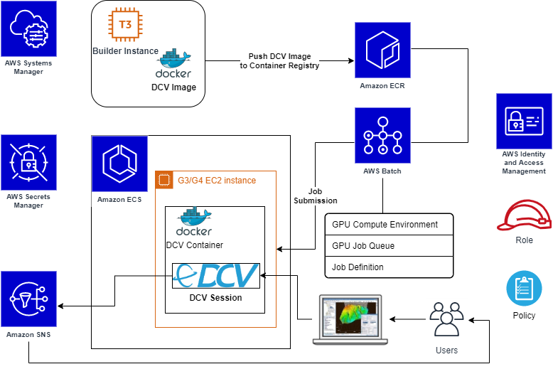
This post provides a step-by-step guide on how to build a container able to run accelerated graphical applications using NICE DCV, and setup AWS Batch to run it. Finally, I will showcase how to submit an AWS Batch job that will provision the compute environment (CE) that contains a set of managed or unmanaged compute resources that are used to run jobs, launch the application in a container, and how to connect to the application with NICE DCV.

Services

Before reviewing the solution, below are the AWS services and products you will use to run your application:

  • AWS Batch (AWS Batch) plans, schedules, and runs batch workloads on Amazon Elastic Container Service (ECS), dynamically provisioning the defined CE with Amazon EC2
  • Amazon Elastic Container Registry (Amazon ECR) is a fully managed Docker container registry that simplifies how developers store, manage, and deploy Docker container images. In this example, you use it to register the Docker image with all the required software stack that will be used from AWS Batch to submit batch jobs.
  • NICE DCV (NICE DCV) is a high-performance remote display protocol that delivers remote desktops and application streaming from any cloud or data center to any device, over varying network conditions. With NICE DCV and Amazon EC2, customers can run graphics-intensive applications remotely on G3/G4 EC2 instances, and stream the results to client machines not provided with a GPU.
  • AWS Secrets Manager (AWS Secrets Manager) helps you to securely encrypt, store, and retrieve credentials for your databases and other services. Instead of hardcoding credentials in your apps, you can make calls to Secrets Manager to retrieve your credentials whenever needed.
  • AWS Systems Manager (AWS Systems Manager) gives you visibility and control of your infrastructure on AWS, and provides a unified user interface so you can view operational data from multiple AWS services. It also allows you to automate operational tasks across your AWS resources. Here it is used to retrieve a public parameter.
  • Amazon Simple Notification Service (Amazon SNS) enables applications, end-users, and devices to instantly send and receive notifications from the cloud. You can send notifications by email to the user who has created a valid and verified subscription.

Solution

The goal of this solution is to run an interactive Linux desktop session in a single Amazon ECS container, with support for GPU rendering, and connect remotely through NICE DCV protocol. AWS Batch will dynamically provision EC2 instances, with or without GPU (e.g. G3/G4 instances).

Solution scheme

You will build and register the DCV Container image to be used for the DCV Desktop Sessions. In AWS Batch, we will set up a managed CE starting from the Amazon ECS GPU-optimized AMI, which comes with the NVIDIA drivers and Amazon ECS agent already installed. Also, you will use Amazon Secrets Manager to safely store user credentials and Amazon SNS to automatically notify the user that the interactive job is ready.

Tutorial

As a Computational Fluid Dynamics (CFD) visualization application example you will use Paraview.

This blog post goes through the following steps:

  1. Prepare required components
    • Launch temporary EC2 instance to build a DCV container image
    • Store user’s credentials and notification data
    • Create required roles
  2. Build DCV container image
  3. Create a repository on Amazon ECR
    • Push the DCV container image
  4. Configure AWS Batch
    • Create a managed CE
    • Create a related job queue
    • Create its Job Definition
  5. Submit a batch job
  6. Connect to the interactive desktop session using NICE DCV
    • Run the Paraview application to visualize results of a job simulation

Prerequisites

  • An Amazon Linux 2 instance as a Docker host, launched from the latest Amazon ECS GPU-optimized AMI
  • In order to connect to desktop sessions, inbound DCV port must be opened (by default DCV port is 8443)
  • AWS account credentials with the necessary access permissions
  • AWS Command Line Interface (CLI) installed and configured with the same AWS credentials
  • To easily install third-party/open source required software, assume that the Docker host has outbound internet access allowed

Step 1. Required components

In this step you’ll create a temporary EC2 instance dedicated to a Docker image, and create the IAM policies required for the next steps. Next create the secrets in AWS Secrets Manager service to store sensible data like credentials and SNS topic ARN, and apply and verify the required system settings.

1.1 Launch the temporary EC2 instance for Docker image building

Launch the EC2 instance that becomes your Docker host from the Amazon ECS GPU-optimized AMI. Retrieve its AMI ID. For cost saving, you can use one of t3* family instance type for this stage (e.g. t3.medium).

1.2 Store user credentials and notification data

As an example of avoiding hardcoded credentials or keys into scripts used in next stages, we’ll use AWS Secrets Manager to safely store final user’s OS credentials and other sensible data.

  • In the AWS Management Console select Secrets Manager, create a new secret, select type Other type of secrets, and specify key pair. Store the user login name as a key, e.g.: user001, and the password as value, then name the secret as Run_DCV_in_Batch, or alternatively you can use the commands. Note xxxxxxxxxx is your chosen password.

aws secretsmanager  create-secret --secret-id Run_DCV_in_Batch
aws secretsmanager put-secret-value --secret-id Run_DCV_in_Batch --secret-string '{"user001":"xxxxxxxxxx"}'

  • Create an SNS Topic to send email notifications to the user when a DCV session is ready for connection:
  • In the AWS Management Console select Secrets Manager service to create a new secret named DCV_Session_Ready_Notification, with type other type of secrets and key pair values. Store the string sns_topic_arn as a key and the SNS Topic ARN as value:

aws secretsmanager  create-secret --secret-id DCV_Session_Ready_Notification
aws secretsmanager put-secret-value --secret-id DCV_Session_Ready_Notification --secret-string '{"sns_topic_arn":"<put here your SNS Topic ARN>"}'

1.3 Create required role and policy

To simplify, define a single role named dcv-ecs-batch-role gathering all the necessary policies. This role will be associated to the EC2 instance that launches from an AWS Batch job submission, so it is included inside the CE definition later.

To allow DCV sessions, push images into Amazon ECR and AWS Batch operations, create the role and include the following AWS managed and custom policies:

  • AmazonEC2ContainerRegistryFullAccess
  • AmazonEC2ContainerServiceforEC2Role
  • SecretsManagerReadWrite
  • AmazonSNSFullAccess
  • AmazonECSTaskExecutionRolePolicy

To reach the NICE DCV licenses stored in Amazon S3 (see licensing the NICE DCV server for more details), define a custom policy named DCVLicensePolicy (the following policy is for eu-west-1 Region, you might also use us-east-1):

{
    "Version": "2012-10-17",
    "Statement": [
        {
            "Effect": "Allow",
            "Action": "s3:GetObject",
            "Resource": "arn:aws:s3:::dcv-license.eu-west-1/*"
        }
    ]
}

create role

Note: If needed, you can add additional policies to allow the copy data from/to S3 bucket.

Update the Trust relationships of the same role in order to allow the Amazon ECS tasks execution and use this role from the AWS Batch Job definition as well:

{
  "Version": "2012-10-17",
  "Statement": [
    {
      "Effect": "Allow",
      "Principal": {
        "Service": "ec2.amazonaws.com"
      },
      "Action": "sts:AssumeRole"
    },
    {
      "Effect": "Allow",
      "Principal": {
        "Service": "ecs-tasks.amazonaws.com"
      },
      "Action": "sts:AssumeRole"
    }
  ]
}

Trusted relationships and Trusted entities

1.4 Create required Security Group

In the AWS Management Console, access EC2, and create a Security Group, named dcv-sg, that is open to DCV sessions and DCV clients by enabling tcp port 8443 in Inbound.

Step 2. DCV container image

Now you will build a container that provides OpenGL acceleration via NICE DCV. You’ll write the Dockerfile starting from Amazon Linux 2 base image, and add DCV with its related requirements.

2.1 Define the Dockerfile

The base software packages in the Dockerfile will contain: NVIDIA libraries, X server and GNOME desktop and some external scripts to manage the DCV service startup and email notification for the user.

Starting from the base image just pulled, our Dockerfile does install all required (and optional) system tools and libraries, desktop manager packages, manage the Prerequisites for Linux NICE DCV Servers , Install the NICE DCV Server on Linux and Paraview application for 2D/3D data visualization.

The final contents of the Dockerfile is available here; in the same repository, you can also find scripts that manage the DCV service system script, the notification message sent to the User, the creation of local User at startup and the run script for the DCV container.

2.2 Build Dockerfile

Install required tools both to unpack archives and perform command on AWS:

sudo yum install -y unzip awscli

Download the Git archive within the EC2 instance, and unpack on a temporary directory:

curl -s -L -o - https://github.com/aws-samples/aws-batch-using-nice-dcv/archive/latest.tar.gz | tar zxvf -

From inside the folder containing aws-batch-using-nice-dcv.dockerfile, let’s build the Docker image:

docker build -t dcv -f aws-batch-using-nice-dcv.dockerfile .

The first time it takes a while since it has to download and install all the required packages and related dependencies. After the command completes, check it has been built and tagged correctly with the command:

docker images

Step 3. Amazon ECR configuration

In this step, you’ll push/archive our newly built DCV container AMI into Amazon ECR. Having this image in Amazon ECR allows you to use it inside Amazon ECS and AWS Batch.

3.1 Push DCV image into Amazon ECR repository

Set a desired name for your new repository, e.g. dcv, and push your latest dcv image into it. The push procedure is described in Amazon ECR by selecting your repository, and clicking on the top-right button View push commands.

Install the required tool to manage content in JSON format:

sudo yum install -y jq

Amazon ECR push commands to run include:

  • Login command to authenticate your Docker client to Amazon ECS registry. Using the AWS CLI:

AWS_REGION="$(curl -s http://169.254.169.254/latest/dynamic/instance-identity/document | jq -r .region)"
eval $(aws ecr get-login --no-include-email --region "${AWS_REGION}") Note: If you receive an “Unknown options: –no-include-email” error when using the AWS CLI, ensure that you have the latest version installed. Learn more.

  • Create the repository:

aws ecr create-repository --repository-name=dcv —region "${AWS_REGION}"DCV_REPOSITORY=$(aws ecr describe-repositories --repository-names=dcv --region "${AWS_REGION}"| jq -r '.repositories[0].repositoryUri')

  • Tag the image to push the image to the Amazon ECR repository:

docker build -t "${DCV_REPOSITORY}:$(date +%F)" -f aws-batch-using-nice-dcv.dockerfile .

  • Push command:

docker push "${DCV_REPOSITORY}:$(date +%F)"

Step 4. AWS Batch configuration

The final step is to set up AWS Batch to manage your DCV containers. The link to all previous steps is the use of our DCV container image inside the AWS Batch CE.

4.1 Compute environment

Create an AWS Batch CE using othe newly created AMI.

  • Log into the AWS Management Console, select AWS Batch, select ‘get started’, and skip the wizard on next page.
  • Choose Compute Environments on the left, and click on Create Environment.
  • Specify all your desired settings, e.g.:
      • Managed type
      • Name: DCV-GPU-CE
      • Service role: AWSBatchServiceRole
      • Instance role: dcv-ecs-batch-role
  • Since you want OpenGL acceleration, choose an instance type with GPU (e.g. g4dn.xlarge).
  • Choose an allocation strategy. In this example I choose BEST_FIT_PROGRESSIVE
  • Assign the security group dcv-sg, created previously at step 1.4 that keeps DCV port 8443 open.
  • Add a Nametag with the value e.g. “DCV-GPU-Batch-Instance”; to assign it to the EC2 instances started by AWS Batch automatically, so you can recognize it if needed.

4.2 Job Queue

Time to create a Job Queue for DCV with your preferred settings.

  • Select Job Queues from the left menu, then select Create queue (naming, for instance, e.g. DCV-GPU-Queue)
  • Specify a required Priority integer value.
  • Associate to this queue the CE you defined in the previous step (e.g. DCV-GPU-CE).

4.3 Job Definition

Now, we create a Job Definition by selecting the related item in the left menu, and select Create. 

We’ll use, listed per section:

  • Job Definition name (e.g. DCV-GPU-JD)
  • Execution timeout to 1h: 3600
  • Parameter section:
    • Add the Parameter named command with value: --network=host
      • Note: This parameter is required and equivalent to specify the same option to the docker run.Learn more.
  • Environment section:
    • Job role: dcv-ecs-batch-role
    • Container image: Use the ECR repository previously created, e.g. dkr.ecr.eu-west-1.amazonaws.com/dcv. If you don’t remember the Amazon ECR image URI, just return to Amazon ECR -> Repository -> Images.
    • vCPUs: 8
      • Note: Value equal to the vCPUs of the chosen instance type (in this example: gdn4.2xlarge), having one job per node to avoid conflicts on usage of TCP ports required by NICE DCV daemons.
    • Memory (MiB): 2048
  • Security section:
    • Check Privileged
    • Set user root (run as root)
  • Environment Variables section:
    • DISPLAY: 0
    • NVIDIA_VISIBLE_DEVICES: 0
    • NVIDIA_ALL_CAPABILITIES: all

Note: Amazon ECS provides a GPU-optimized AMI that comes ready with pre-configured NVIDIA kernel drivers and a Docker GPU runtime, learn more; the variables above make available the required graphic device(s) inside the container.

4.4 Create and submit a Job

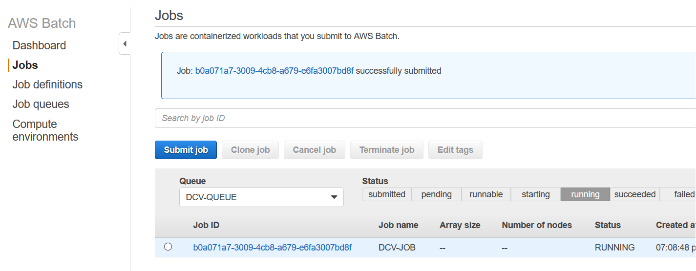
We can finally, create an AWS Batch job, by selecting Batch → Jobs → Submit Job.
Let’s specify the job queue and job definition defined in the previous steps. Leave the command filed as pre-filled from job definition.

Running DCV job on AWS Batch

4.5 Connect to sessions

Once the job is in RUNNING state, go to the AWS Batch dashboard, you can get the IP address/DNS in several ways as noted in How do I get the ID or IP address of an Amazon EC2 instance for an AWS Batch job. For example, assuming the tag Name set on CE is DCV-GPU-Batch-Instance:

aws ec2 describe-instances --filters Name=instance-state-name,Values=running Name=tag:Name,Values="DCV-GPU-Batch-Instance" --query "Reservations[].Instances[].{id: InstanceId, tm: LaunchTime, ip: PublicIpAddress}" | jq -r 'sort_by(.tm) | reverse | .[0]' | jq -r .ip

Note: It could be required to add the EC2 policy to the list of instances in the IAM role. If the AWS SNS Topic is properly configured, as mentioned in subsection 1.2, you receive the notification email message with the URL link to connect to the interactive graphical DCV session.

Email from SNS

Finally, connect to it:

  • https://<ip address>:8443

Note: You might need to wait for the host to report as running on EC2 in AWS Management Console.

Below is a NICE DCV session running inside a container using the web browser, or equivalently the NICE DCV native client as well, running Paraview visualization application. It shows the basic elbow results coming from an external OpenFoam simulation, which data has been previously copied over from an S3 bucket; and the dcvgltest as well:

DCV Client connected to a running session

Cleanup

Once you’ve finished running the application, avoid incurring future charges by navigating to the AWS Batch console and terminate the job, set CE parameter Minimum vCPUs and Desired vCPUs equal to 0. Also, navigate to Amazon EC2 and stop the temporary EC2 instance used to build the Docker image.

For a full cleanup of all of the configurations and resources used, delete: the job definition, the job queue and the CE (AWS Batch), the Docker image and ECR Repository (Amazon ECR), the role dcv-ecs-batch-role (Amazon IAM), the security group dcv-sg (Amazon EC2), the Topic DCV_Session_Ready_Notification (AWS SNS), and the secret Run_DCV_in_Batch (Amazon Secrets Manager).

Conclusion

This blog post demonstrates how AWS Batch enables innovative approaches to run HPC workflows including not only batch jobs, but also pre-/post-analysis steps done through interactive graphical OpenGL/3D applications.

You are now ready to start interactive applications with AWS Batch and NICE DCV on G-series instance types with dedicated 3D hardware. This allows you to take advantage of graphical remote rendering on optimized infrastructure without moving data to save costs.

On Risk-Based Authentication

Post Syndicated from Bruce Schneier original https://www.schneier.com/blog/archives/2020/10/on-risk-based-authentication.html

Interesting usability study: “More Than Just Good Passwords? A Study on Usability and Security Perceptions of Risk-based Authentication“:

Abstract: Risk-based Authentication (RBA) is an adaptive security measure to strengthen password-based authentication. RBA monitors additional features during login, and when observed feature values differ significantly from previously seen ones, users have to provide additional authentication factors such as a verification code. RBA has the potential to offer more usable authentication, but the usability and the security perceptions of RBA are not studied well.

We present the results of a between-group lab study (n=65) to evaluate usability and security perceptions of two RBA variants, one 2FA variant, and password-only authentication. Our study shows with significant results that RBA is considered to be more usable than the studied 2FA variants, while it is perceived as more secure than password-only authentication in general and comparably se-cure to 2FA in a variety of application types. We also observed RBA usability problems and provide recommendations for mitigation.Our contribution provides a first deeper understanding of the users’perception of RBA and helps to improve RBA implementations for a broader user acceptance.

Paper’s website. I’ve blogged about risk-based authentication before.

COVID-19 and Acedia

Post Syndicated from Bruce Schneier original https://www.schneier.com/blog/archives/2020/10/covid-19-and-acedia.html

Note: This isn’t my usual essay topic. Still, I want to put it on my blog.

Six months into the pandemic with no end in sight, many of us have been feeling a sense of unease that goes beyond anxiety or distress. It’s a nameless feeling that somehow makes it hard to go on with even the nice things we regularly do.

What’s blocking our everyday routines is not the anxiety of lockdown adjustments, or the worries about ourselves and our loved ones — real though those worries are. It isn’t even the sense that, if we’re really honest with ourselves, much of what we do is pretty self-indulgent when held up against the urgency of a global pandemic.

It is something more troubling and harder to name: an uncertainty about why we would go on doing much of what for years we’d taken for granted as inherently valuable.

What we are confronting is something many writers in the pandemic have approached from varying angles: a restless distraction that stems not just from not knowing when it will all end, but also from not knowing what that end will look like. Perhaps the sharpest insight into this feeling has come from Jonathan Zecher, a historian of religion, who linked it to the forgotten Christian term: acedia.

Acedia was a malady that apparently plagued many medieval monks. It’s a sense of no longer caring about caring, not because one had become apathetic, but because somehow the whole structure of care had become jammed up.

What could this particular form of melancholy mean in an urgent global crisis? On the face of it, all of us care very much about the health risks to those we know and don’t know. Yet lurking alongside such immediate cares is a sense of dislocation that somehow interferes with how we care.

The answer can be found in an extreme thought experiment about death. In 2013, philosopher Samuel Scheffler explored a core assumption about death. We all assume that there will be a future world that survives our particular life, a world populated by people roughly like us, including some who are related to us or known to us. Though we rarely or acknowledge it, this presumed future world is the horizon towards which everything we do in the present is oriented.

But what, Scheffler asked, if we lose that assumed future world — because, say, we are told that human life will end on a fixed date not far after our own death? Then the things we value would start to lose their value. Our sense of why things matter today is built on the presumption that they will continue to matter in the future, even when we ourselves are no longer around to value them.

Our present relations to people and things are, in this deep way, future-oriented. Symphonies are written, buildings built, children conceived in the present, but always with a future in mind. What happens to our ethical bearings when we start to lose our grip on that future?

It’s here, moving back to the particular features of the global pandemic, that we see more clearly what drives the restlessness and dislocation so many have been feeling. The source of our current acedia is not the literal loss of a future; even the most pessimistic scenarios surrounding COVID-19 have our species surviving. The dislocation is more subtle: a disruption in pretty much every future frame of reference on which just going on in the present relies.

Moving around is what we do as creatures, and for that we need horizons. COVID-19 has erased many of the spatial and temporal horizons we rely on, even if we don’t notice them very often. We don’t know how the economy will look, how social life will go on, how our home routines will be changed, how work will be organized, how universities or the arts or local commerce will survive.

What unsettles us is not only fear of change. It’s that, if we can no longer trust in the future, many things become irrelevant, retrospectively pointless. And by that we mean from the perspective of a future whose basic shape we can no longer take for granted. This fundamentally disrupts how we weigh the value of what we are doing right now. It becomes especially hard under these conditions to hold on to the value in activities that, by their very nature, are future-directed, such as education or institution-building.

That’s what many of us are feeling. That’s today’s acedia.

Naming this malaise may seem more trouble than its worth, but the opposite is true. Perhaps the worst thing about medieval acedia was that monks struggled with its dislocation in isolation. But today’s disruption of our sense of a future must be a shared challenge. Because what’s disrupted is the structure of care that sustains why we go on doing things together, and this can only be repaired through renewed solidarity.

Such solidarity, however, has one precondition: that we openly discuss the problem of acedia, and how it prevents us from facing our deepest future uncertainties. Once we have done that, we can recognize it as a problem we choose to face together — across political and cultural lines — as families, communities, nations and a global humanity. Which means doing so in acceptance of our shared vulnerability, rather than suffering each on our own.

This essay was written with Nick Couldry, and previously appeared on CNN.com.

Ultrasonically detect bats with Raspberry Pi

Post Syndicated from Ashley Whittaker original https://www.raspberrypi.org/blog/ultrasonically-detect-bats-with-raspberry-pi/

Welcome to October, the month in which spiderwebs become decor and anything vaguely gruesome is considered ‘seasonal’. Such as bats. Bats are in fact cute, furry creatures, but as they are part of the ‘Halloweeny animal’ canon, I have a perfect excuse to sing their praises.

baby bats in a row wrapped up like human babies
SEE? Baby bats wrapped up cute like baby humans

Tegwyn Twmffat was tasked with doing a bat survey on a derelict building, and they took to DesignSpark to share their Raspberry Pi–powered solution.

UK law protects nesting birds and roosting bats, so before you go knocking buildings down, you need a professional to check that no critters will be harmed in the process.

The acoustic signature of an echo-locating brown long-eared bat

The problem with bats, compared to birds, is they are much harder to spot and have a tendency to hang out in tiny wall cavities. Enter this big ultrasonic microphone.

Raspberry Pi 4 Model B provided the RAM needed for this build

After the building was declared safely empty of bats, Tegwyn decided to keep hold of the expensive microphone (the metal tube in the image above) and have a crack at developing their own auto-classification system to detect which type of bats are about.

How does it work?

The ultrasonic mic picks up the audio data using an STM M0 processor and streams it to Raspberry Pi via USB. Raspberry Pi runs Alsa driver software and uses the bash language to receive the data.

Tegwyn turned to the open-source GTK software to process the audio data

It turns out there are no publicly available audio records of bats, so Tegwyn took to their own back garden and found 6 species to record. And with the help of a few other bat enthusiasts, they cobbled together an audio dataset of 9 of the 17 bat species found in the UK!

Tegwyn’s original post about their project features a 12-step walkthrough, as well as all the code and commands you’ll need to build your own system. And here’s the GitHub repository, where you can check for updates.

The post Ultrasonically detect bats with Raspberry Pi appeared first on Raspberry Pi.

Code a Rally-X-style mini-map | Wireframe #43

Post Syndicated from Ryan Lambie original https://www.raspberrypi.org/blog/code-a-rally-x-style-mini-map-wireframe-43/

Race around using a mini-map for navigation, just like the arcade classic, Rally-X. Mark Vanstone has the code

In Namco’s original arcade game, the red cars chased the player relentlessly around each level. Note the handy mini-map on the right.

The original Rally-X arcade game blasted onto the market in 1980, at the same time as Pac‑Man and Defender. This was the first year that developer Namco had exported its games outside Japan thanks to the deal it struck with Midway, an American game distributor. The aim of Rally-X is to race a car around a maze, avoiding enemy cars while collecting yellow flags – all before your fuel runs out.

The aspect of Rally-X that we’ll cover here is the mini-map. As the car moves around the maze, its position can be seen relative to the flags on the right of the screen. The main view of the maze only shows a section of the whole map, and scrolls as the car moves, whereas the mini-map shows the whole size of the map but without any of the maze walls – just dots where the car and flags are (and in the original, the enemy cars). In our example, the mini-map is five times smaller than the main map, so it’s easy to work out the calculation to translate large map co‑ordinates to mini-map co-ordinates.

To set up our Rally-X homage in Pygame Zero, we can stick with the default screen size of 800×600. If we use 200 pixels for the side panel, that leaves us with a 600×600 play area. Our player’s car will be drawn in the centre of this area at the co-ordinates 300,300. We can use the in-built rotation of the Actor object by setting the angle property of the car. The maze scrolls depending on which direction the car is pointing, and this can be done by having a lookup table in the form of a dictionary list (directionMap) where we define x and y increments for each angle the car can travel. When the cursor keys are pressed, the car stays central and the map moves.

A screenshot of our Rally-X homage running in Pygame Zero

Roam the maze and collect those flags in our Python homage to Rally-X.

To detect the car hitting a wall, we can use a collision map. This isn’t a particularly memory-efficient way of doing it, but it’s easy to code. We just use a bitmap the same size as the main map which has all the roads as black and all the walls as white. With this map, we can detect if there’s a wall in the direction in which the car’s moving by testing the pixels directly in front of it. If a wall is detected, we rotate the car rather than moving it. If we draw the side panel after the main map, we’ll then be able to see the full layout of the screen with the map scrolling as the car navigates through the maze.

We can add flags as a list of Actor objects. We could make these random, but for the sake of simplicity, our sample code has them defined in a list of x and y co-ordinates. We need to move the flags with the map, so in each update(), we loop through the list and add the same increments to the x and y co‑ordinates as the main map. If the car collides with any flags, we just take them off the list of items to draw by adding a collected variable. Having put all of this in place, we can draw the mini-map, which will show the car and the flags. All we need to do is divide the object co-ordinates by five and add an x and y offset so that the objects appear in the right place on the mini-map.

And those are the basics of Rally-X! All it needs now is a fuel gauge, some enemy cars, and obstacles – but we’ll leave those for you to sort out…

Here’s Mark’s code for a Rally-X-style driving game with mini-map. To get it running on your system, you’ll need to install Pygame Zero. And to download the full code and assets, head here.

Get your copy of Wireframe issue 43

You can read more features like this one in Wireframe issue 43, available directly from Raspberry Pi Press — we deliver worldwide.

And if you’d like a handy digital version of the magazine, you can also download issue 43 for free in PDF format.

Wireframe #43, with the gorgeous Sea of Stars on the cover.

Make sure to follow Wireframe on Twitter and Facebook for updates and exclusive offers and giveaways. Subscribe on the Wireframe website to save up to 49% compared to newsstand pricing!


The post Code a Rally-X-style mini-map | Wireframe #43 appeared first on Raspberry Pi.

Negotiating with Ransomware Gangs

Post Syndicated from Bruce Schneier original https://www.schneier.com/blog/archives/2020/09/negotiating-with-ransomware-gangs.html

Really interesting conversation with someone who negotiates with ransomware gangs:

For now, it seems that paying ransomware, while obviously risky and empowering/encouraging ransomware attackers, can perhaps be comported so as not to break any laws (like anti-terrorist laws, FCPA, conspiracy and others) ­ and even if payment is arguably unlawful, seems unlikely to be prosecuted. Thus, the decision whether to pay or ignore a ransomware demand, seems less of a legal, and more of a practical, determination ­ almost like a cost-benefit analysis.

The arguments for rendering a ransomware payment include:

  • Payment is the least costly option;
  • Payment is in the best interest of stakeholders (e.g. a hospital patient in desperate need of an immediate operation whose records are locked up);
  • Payment can avoid being fined for losing important data;
  • Payment means not losing highly confidential information; and
  • Payment may mean not going public with the data breach.

The arguments against rendering a ransomware payment include:

  • Payment does not guarantee that the right encryption keys with the proper decryption algorithms will be provided;
  • Payment further funds additional criminal pursuits of the attacker, enabling a cycle of ransomware crime;
  • Payment can do damage to a corporate brand;
  • Payment may not stop the ransomware attacker from returning;
  • If victims stopped making ransomware payments, the ransomware revenue stream would stop and ransomware attackers would have to move on to perpetrating another scheme; and
  • Using Bitcoin to pay a ransomware attacker can put organizations at risk. Most victims must buy Bitcoin on entirely unregulated and free-wheeling exchanges that can also be hacked, leaving buyers’ bank account information stored on these exchanges vulnerable.

When confronted with a ransomware attack, the options all seem bleak. Pay the hackers ­ and the victim may not only prompt future attacks, but there is also no guarantee that the hackers will restore a victim’s dataset. Ignore the hackers ­ and the victim may incur significant financial damage or even find themselves out of business. The only guarantees during a ransomware attack are the fear, uncertainty and dread inevitably experienced by the victim.

Raspberry Pi reaches more schools in rural Togo

Post Syndicated from Ashley Whittaker original https://www.raspberrypi.org/blog/raspberry-pi-reaches-more-schools-in-rural-togo/

We’ve been following the work of Dominique Laloux since he first got in touch with us in May 2013 ahead of leaving to spend a year in Togo. 75% of teachers in the region where he would be working had never used a computer before 2012, so he saw an opportunity to introduce Raspberry Pi and get some training set up.

We were so pleased to receive another update this year about Dominique and his Togolese team’s work. This has grown to become INITIC, a non-profit organisation that works to install low cost, low power consumption, low maintenance computer rooms in rural schools in Togo. The idea for the acronym came from the organisation’s focus on the INItiation of young people to ICT (TIC in French).

Visit the INTIC website to learn more

The story so far

INITIC’s first computer room was installed in Tokpli, Togo, way back in 2012. It was a small room (see the photo on the left below) donated by an agricultural association and renovated by a team of villagers.

Fast forward to 2018, and INTIC had secured its own building (photo on the right above). It has a dedicated a Raspberry Pi Room, as well as a multipurpose room and another small technical room. Young people from local schools, as well as those in neighbouring villages, have access to the facilities.

The first dedicated Raspberry Pi Room in Togo was at the Collège (secondary school) in the town of Kuma Adamé. It was equipped with 21 first-generation Raspberry Pis, which stood up impressively against humid and dusty conditions.

In 2019, Kpodzi High School also got its own Raspberry Pi Room, equipped with 22 Raspberry Pi workstations. Once the projector, laser printer, and scanners are in place, the space will also be used for electronics, Arduino, and programming workshops.

What’s the latest?

Ready for the unveiling…

Now we find ourselves in 2020 and INTIC is still growing. Young people in the bountiful, but inaccessible, village of Danyi Dzogbégan now have access to 20 Raspberry Pi workstations (plus one for the teacher). They have been using them for learning since January this year.

We can’t wait to see what Dominique and his team have up their sleeve next. You can help INTIC reach more young people in rural Togo by donating computer equipment, by helping teachers get lesson materials together, or through a volunteer stay at one of their facilities. Find out more here.

The post Raspberry Pi reaches more schools in rural Togo appeared first on Raspberry Pi.

Hacking a Coffee Maker

Post Syndicated from Bruce Schneier original https://www.schneier.com/blog/archives/2020/09/hacking-a-coffee-maker.html

As expected, IoT devices are filled with vulnerabilities:

As a thought experiment, Martin Hron, a researcher at security company Avast, reverse engineered one of the older coffee makers to see what kinds of hacks he could do with it. After just a week of effort, the unqualified answer was: quite a lot. Specifically, he could trigger the coffee maker to turn on the burner, dispense water, spin the bean grinder, and display a ransom message, all while beeping repeatedly. Oh, and by the way, the only way to stop the chaos was to unplug the power cord.

[…]

In any event, Hron said the ransom attack is just the beginning of what an attacker could do. With more work, he believes, an attacker could program a coffee maker — ­and possibly other appliances made by Smarter — ­to attack the router, computers, or other devices connected to the same network. And the attacker could probably do it with no overt sign anything was amiss.

On Executive Order 12333

Post Syndicated from Bruce Schneier original https://www.schneier.com/blog/archives/2020/09/on-executive-order-12333.html

Mark Jaycox has written a long article on the US Executive Order 12333: “No Oversight, No Limits, No Worries: A Primer on Presidential Spying and Executive Order 12,333“:

Abstract: Executive Order 12,333 (“EO 12333”) is a 1980s Executive Order signed by President Ronald Reagan that, among other things, establishes an overarching policy framework for the Executive Branch’s spying powers. Although electronic surveillance programs authorized by EO 12333 generally target foreign intelligence from foreign targets, its permissive targeting standards allow for the substantial collection of Americans’ communications containing little to no foreign intelligence value. This fact alone necessitates closer inspection.

This working draft conducts such an inspection by collecting and coalescing the various declassifications, disclosures, legislative investigations, and news reports concerning EO 12333 electronic surveillance programs in order to provide a better understanding of how the Executive Branch implements the order and the surveillance programs it authorizes. The Article pays particular attention to EO 12333’s designation of the National Security Agency as primarily responsible for conducting signals intelligence, which includes the installation of malware, the analysis of internet traffic traversing the telecommunications backbone, the hacking of U.S.-based companies like Yahoo and Google, and the analysis of Americans’ communications, contact lists, text messages, geolocation data, and other information.

After exploring the electronic surveillance programs authorized by EO 12333, this Article proposes reforms to the existing policy framework, including narrowing the aperture of authorized surveillance, increasing privacy standards for the retention of data, and requiring greater transparency and accountability.

Raspberry Pi High Quality Camera takes photos through thousands of straws

Post Syndicated from Ashley Whittaker original https://www.raspberrypi.org/blog/raspberry-pi-high-quality-camera-takes-photos-through-thousands-of-straws/

Adrian Hanft is our favourite kind of maker: weird. He’s also the guy who invented the Lego camera, 16 years ago. This time, he spent more than a year creating what he describes as “one of the strangest cameras you may ever hear about.”

What? Looks normal from here. Massive, but normal

What’s with all the straws?

OK, here’s why it’s weird: it takes photos with a Raspberry Pi High Quality Camera through a ‘lens’ of tiny drinking straws packed together. 23,248 straws, to be exact, are inside the wooden box-shaped bit of the machine above. The camera itself sits at the slim end of the black and white part. The Raspberry Pi, power bank, and controller all sit on top of the wooden box full of straws.

Here’s what an image of Yoda looks like, photographed through that many straws:

Mosaic, but make it techy

Ground glass lenses

The concept isn’t as easy as it may look. As you can see from the images below, if you hold up a load of straws, you can only see the light through a few of them. Adrian turned to older technology for a solution, taking a viewfinder from an old camera which had ground glass (which ‘collects’ light) on the surface.

Left: looking through straws at light with the naked eye
Right: the same straws viewed through a ground glass lens

Even though Adrian was completely new to both Raspberry Pi and Python, it only took him a week of evenings and weekends to code the software needed to control the Raspberry Pi High Quality Camera.

Long story short, on the left is the final camera, with all the prototypes queued up behind it

An original Nintendo controller runs the show and connects to the Raspberry Pi with a USB adapter. The buttons are mapped to the functions of Adrian’s software.

A super satisfying time-lapse of the straws being loaded

What does the Nintendo controller do?

In his original post, Adrian explains what all the buttons on the controller do in order to create images:

“The Start button launches a preview of what the camera is seeing. The A button takes a picture. The Up and Down buttons increase or decrease the exposure time by 1 second. The Select button launches a gallery of photos so I can see the last photo I took. The Right and Left buttons cycle between photos in the gallery. I am saving the B button for something else in the future. Maybe I will use it for uploading to Dropbox, I haven’t decided yet.”

Adrian made a Lego mount for the Raspberry Pi camera
The Lego mount makes it easy to switch between cameras and lenses

A mobile phone serves as a wireless display so he can keep an eye on what’s going on. The phone communicates with the Raspberry Pi connected to the camera via a VPN app.

One of the prototypes in action

Follow Adrian on Instagram to keep up with all the photography captured using the final camera, as well as the prototypes that came before it.

The post Raspberry Pi High Quality Camera takes photos through thousands of straws appeared first on Raspberry Pi.