Post Syndicated from Ashok Srirama original https://aws.amazon.com/blogs/architecture/migrate-resources-between-aws-accounts/
Have you ever wondered how to move resources between Amazon Web Services (AWS) accounts? You can really view this as a migration of resources. Migrating resources from one AWS account to another may be desired or required due to your business needs. Following are a few scenarios where this may be of benefit:
- When you acquire, sell, or merge overseas operations from other businesses.
- When you move regional operations from one Managed Service Provider (MSP) to another.
- When you reorganize your AWS account and organizational structure.
This process may involve migrating the infrastructure either partially or completely.
In this blog, we will discuss various approaches to migrating resources based on type, configuration, and workload needs. Usually, the first consideration is infrastructure. What’s in your environment? What are the interdependencies? How will you migrate each resource?
Using this information, you can outline a plan on how you will approach migrating each of the resources in your portfolio, and in what order.
Here are some considerations to address for a typical migration:
- Infrastructure – This includes resources required to run your workloads that do not have any persistent data. Examples are AWS Lambda functions, Amazon Elastic Container Service clusters, Elastic load balancers, and more.
- Compute – This includes Amazon Elastic Compute Cloud (Amazon EC2) instances that store persistent data in Amazon Elastic Block Store (EBS) volumes.
- Storage – This includes file and object storage services like Amazon Simple Storage Service (S3), Amazon Elastic File System (EFS), or others.
- Database – This includes managed database services like Amazon Relational Database Service (RDS), Amazon DynamoDB, and Amazon Redshift.
Let’s look at each of these considerations in detail.
Migrating infrastructure
To migrate infrastructure that includes ephemeral resources, you can use one of the following Infrastructure as Code (IaC) approaches, shown in Figure 1. IaC templates are like programming scripts that automate the provisioning of IT resources.
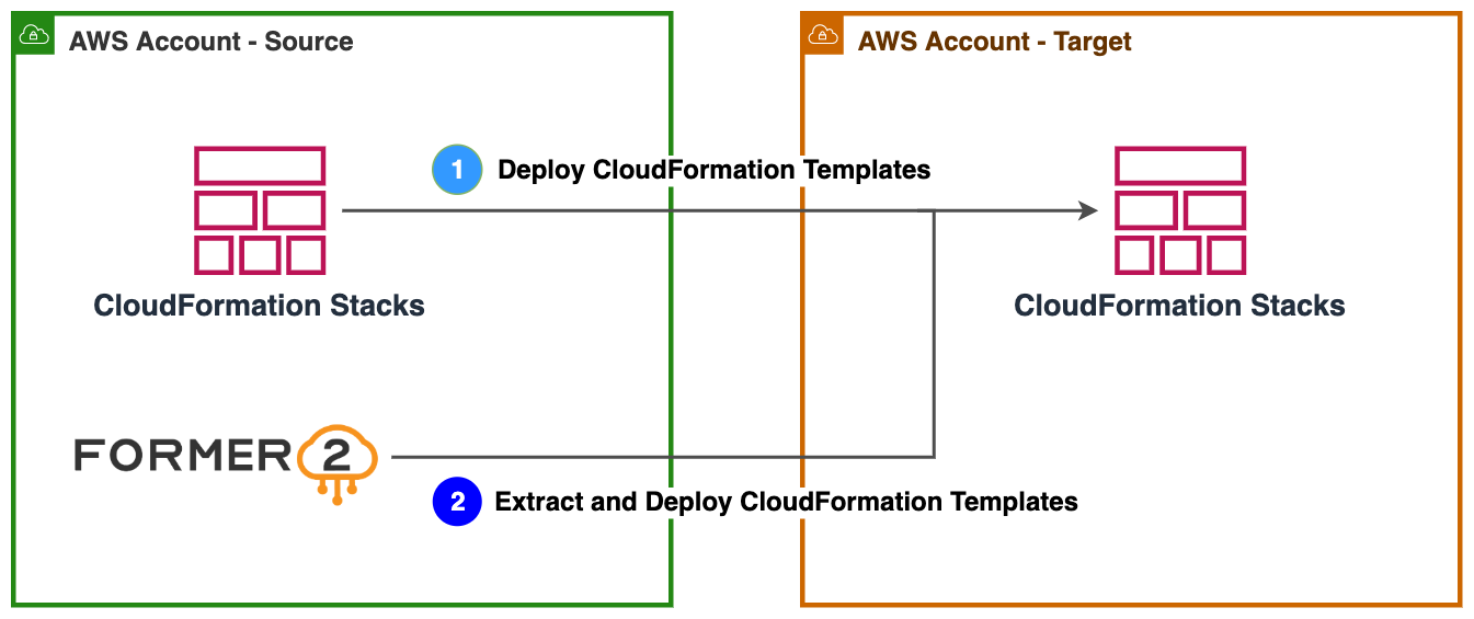
Figure 1. Approaches to migrate infrastructure using IaC
1. If you are already using AWS CloudFormation templates, you can easily import the existing templates to the target AWS account.
AWS CloudFormation simplifies provisioning and management on AWS. You can create templates for quick and reliable provisioning of services or applications (called “stacks”).
2. You can use tools like Former2 to templatize your existing resources in the source AWS account and deploy them in the target account.
Former2 is an open-source project that allows you to generate IaC templates. For example, AWS CloudFormation or HashiCorp Terraform can be generated from the existing resources within your AWS account. Read Accelerate infrastructure as code development with open source Former2 for step-by-step guidance.
Migrating compute resources
To migrate compute resources that have a persistent state, you can use one of the following approaches, shown in Figure 2. These provide a virtual computing environment, allowing you to launch instances with a variety of operating systems.
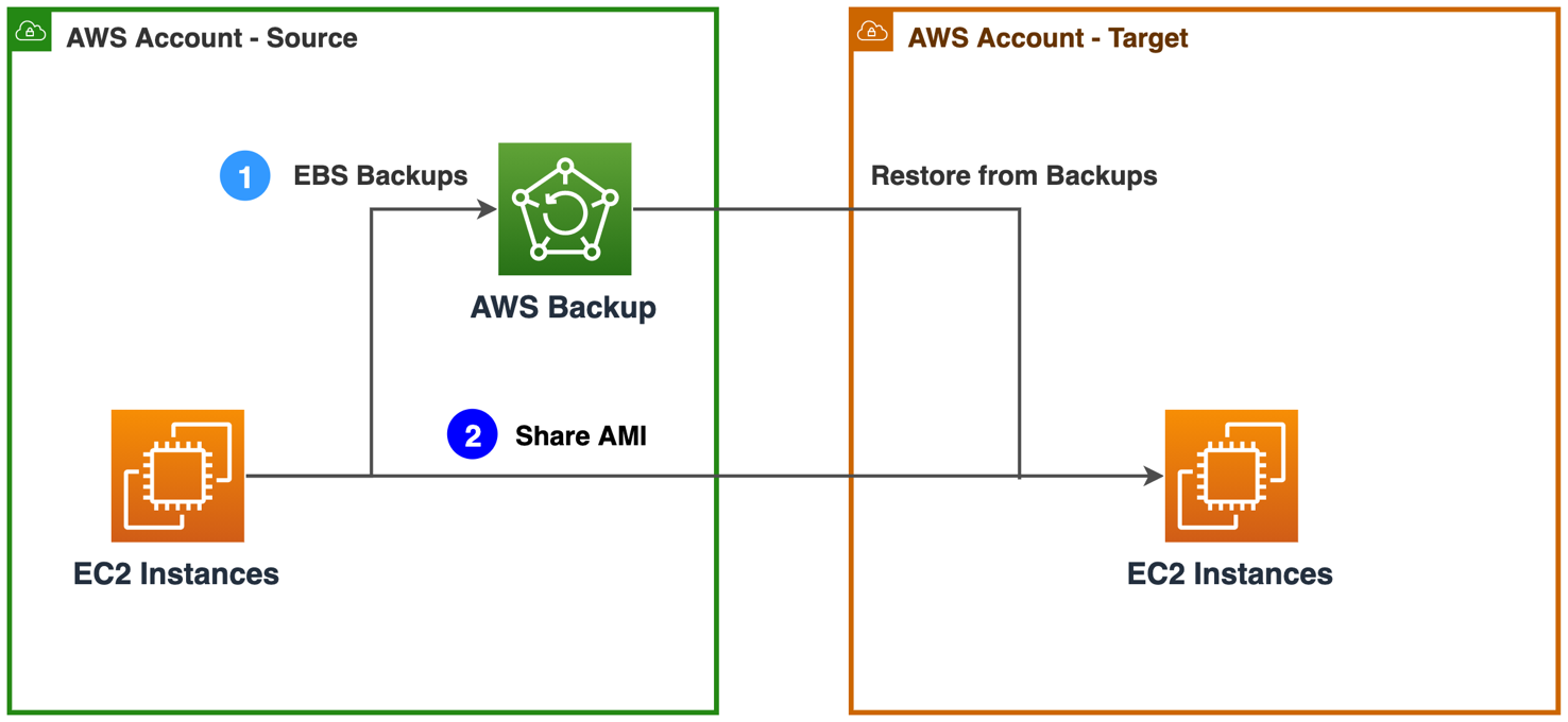
Figure 2. Approaches to migrate compute resources
1. If you are already using AWS Backup service and AWS Organizations to centrally manage backup policies, you can enable AWS Backup cross-account management feature. This manages, monitors, restores your backup, and copies jobs across AWS accounts. Ensure you have both accounts in same AWS Organization. Once the backups are available in the target account, you can restore EC2 instances. Follow detailed instructions at Creating backup copies across AWS accounts.
AWS Backup is a fully managed data protection service that centralizes and automates data across AWS services, in the cloud, and on-premises. You can configure backup policies and monitor activity for your AWS resources. You can automate and consolidate backup tasks that were previously performed service-by-service. This removes the need to create custom scripts and use manual processes.
2. Create an Amazon Machine Image of your EC2 instances and share it with the target account. You can launch new EC2 instances using the shared AMI. Follow step-by-step instructions: How do I transfer an Amazon EC2 instance or AMI to a different AWS account?
Amazon Machine Image (AMI) provides the information required to launch an instance. Specify an AMI and then launch multiple instances from a single AMI with the same configuration. You can use different AMIs to launch instances when you need instances with different configurations.
For migrating non-persistent compute resources, refer Migrating Infrastructure section.
Migrating storage resources
AWS offers various storage services including object, file, and block storage. To migrate objects from a S3 bucket, you can take the following approaches, shown in Figure 3a.
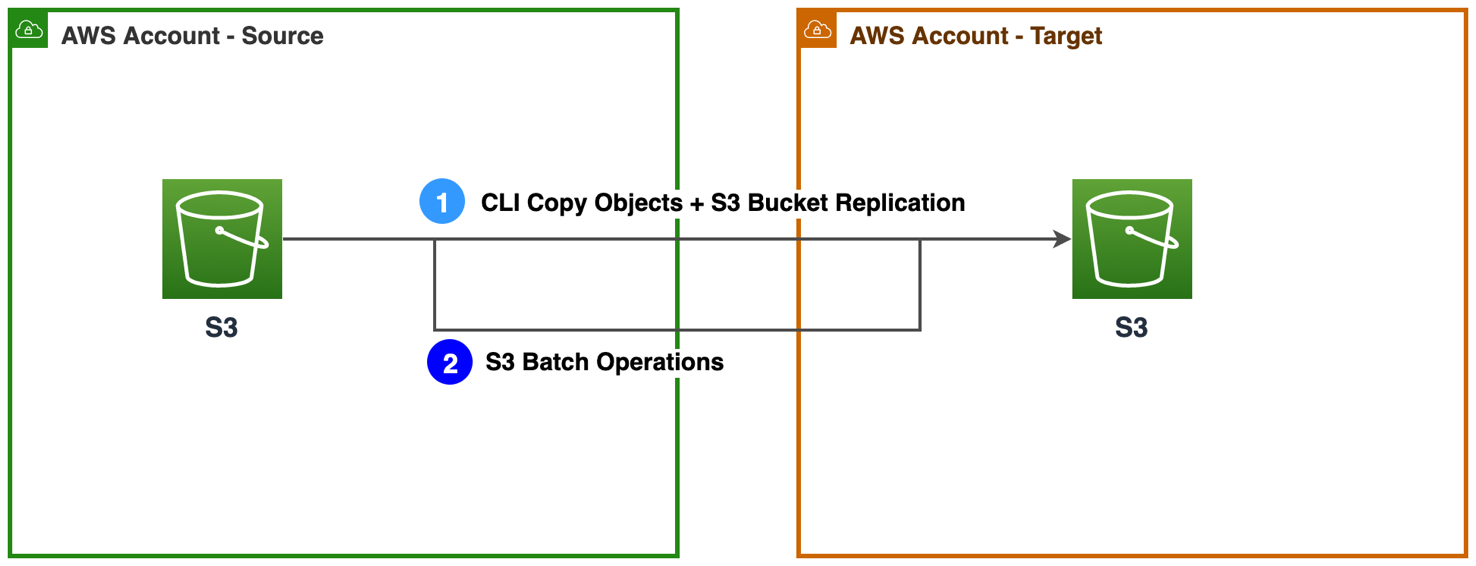
Figure 3a. Approaches to migrate S3 buckets
1. Use Amazon S3 command line interface (CLI) commands to copy the initial load of objects from the source account to the target account. Read How can I copy S3 objects from another AWS account? After the initial copy, you can enable Amazon S3 replication feature to continuously replicate object changes across accounts. Add a bucket policy to grant source bucket permission to replicate objects in destination bucket. Read this walkthrough on how to configure replications.
2. If the S3 bucket contains large number of objects, use Amazon S3 Batch operations to copy objects across AWS accounts in bulk. Read Cross-account bulk transfer of files using Amazon S3 Batch Operations.
To migrate files from an Amazon EFS file system, you can take the following approach, shown in Figure 3b.
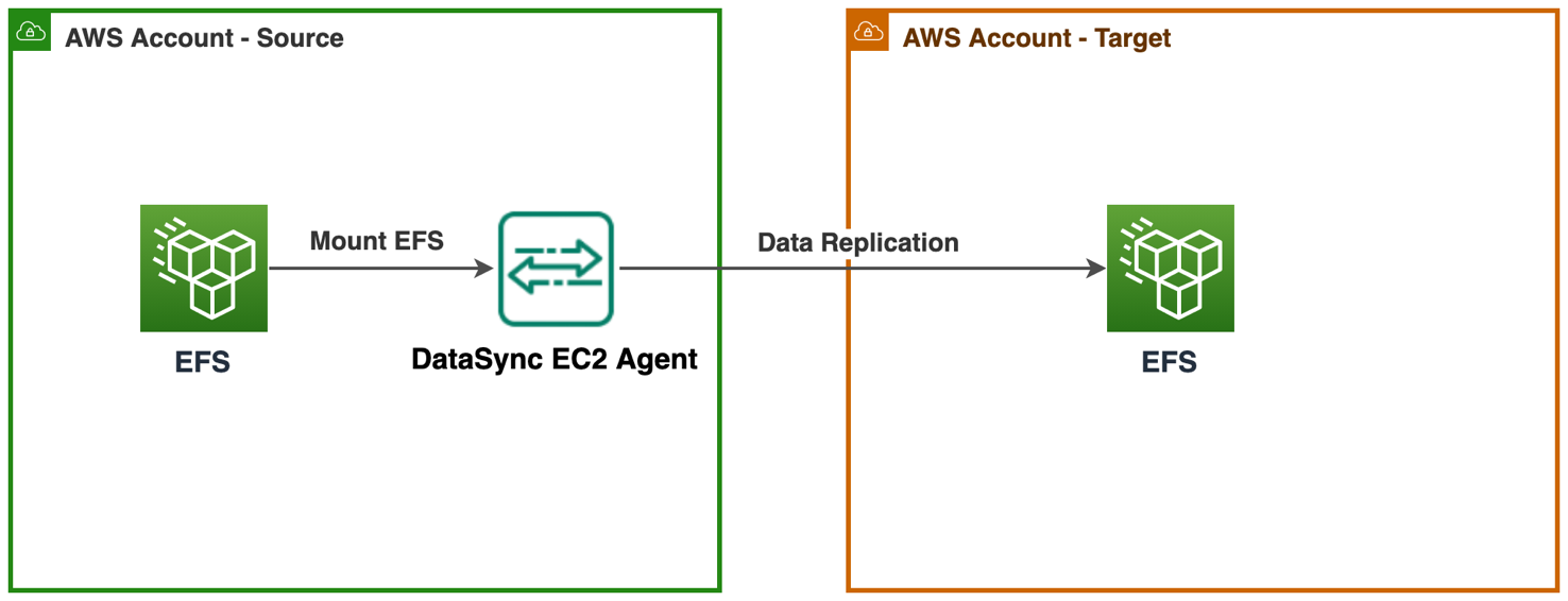
Figure 3b. Approach to migrate EFS file systems
Use AWS DataSync agent to transfer data from one EFS file system to another. AWS DataSync is an online transfer service that simplifies moving, copying, and synchronizing large amounts of data between on-premises storage systems and AWS storage services. Read Transferring file data across AWS Regions and accounts using AWS DataSync for step-by-step guidance.
Migrating database resources
AWS offers various purpose-built database engines. These include relational, key-value, document, in-memory, graph, time series, wide column, and ledger databases. To migrate relational databases, you can take one of the following approaches, shown in Figure 4.
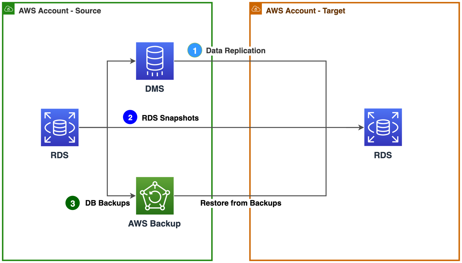
Figure 4. Approaches to migrate relational database resources
1. If you want to continuously replicate data changes, use AWS Database Migration Service (AWS DMS) to replicate your data across AWS accounts with high availability. The source database remains fully operational during the migration, minimizing downtime to applications that rely on the database. You can set up a DMS task for either one-time migration or on-going replication. An on-going replication task keeps your source and target databases in sync. Once set up, the on-going replication task will continuously apply source changes to the target with minimal latency. Learn how to Set Up AWS DMS for Cross-Account Migration.
AWS DMS is a cloud service that streamlines the migration of relational databases, data warehouses, NoSQL databases, and other types of data stores. You can use AWS DMS to migrate your data into the AWS Cloud or between combinations of cloud and on-premises setups.
2. Use RDS Snapshots to create and share database backups across AWS accounts. Use the shared snapshots to launch new Amazon Relational Database Service (RDS) instances in the target account. Read step-by-step instructions: How can I share an encrypted Amazon RDS DB snapshot with another account?
3. Use AWS Backup to create backup policies that automatically back up your AWS resources. Use AWS Backup cross-account management feature to manage and monitor your backup, restore, and copy jobs across AWS accounts. Once the backups are available in the target account, you can restore RDS instances. Learn about Creating backup copies across AWS accounts.
In this section, we discussed relational databases migration. You can also use AWS DMS for migrating other databases. Read supported AWS DMS source and target databases.
Conclusion
In this blog post, we discussed various approaches you can take to migrate resources from one account to another depending upon the resource type and configuration. Additionally, you can also explore CloudEndure Migration for continuous data replication. Learn more about Migrating workloads across AWS Regions with CloudEndure Migration.