Tag Archives: Case Study

Monitoring Self-Service Markets with Zabbix and IoT

Post Syndicated from Aurea Araujo original https://blog.zabbix.com/monitoring-self-service-markets-with-zabbix-and-iot/28422/

QU!CK Scan & Go, a startup specializing in self-service markets, required a monitoring system that could allow a comprehensive view of operations. Read on to see how Zabbix provided them with a solution that positively impacted their operations as well as their finances.

The convenience of having access to an establishment supplying staple foods around the clock is the motivating factor behind the rise of QU!CK Scan & Go. Since 2021, QU!CK Scan & Go has been developing self-service mini market systems, available in residential complexes and corporate buildings.

Available 24 hours a day, 7 days a week, the technology developed by QU!CK Scan & Go allows markets to be open at all times, with 100% self-service. Customers select the products they want, confirm the price by scanning a barcode, and complete the purchase in their own app with a credit card or virtual wallet.

QU!CK Scan & Go was the first company in the self-service market segment to operate in Argentina. As of this writing, they have 25 self-service stores located in Argentina and 2 in the United States.

The challenge

With the rapid growth in their business, QU!CK Scan & Go needed to be able to easily visualize operations in order to handle environmental issues and avoid product loss due to external factors. In the event of a power outage, for instance, refrigerators and freezers will fail to function, a problem that may take considerable time and effort to fix.

This scenario  isn’t an abstract hypothetical – power outages are a recurring issue in Argentina. In 2021 and 2022, the average length of a power outage was 5 hours. For freezers storing products such as ice cream, frozen processed foods, and other perishable items, that’s more than enough time for the products to thaw and become unusable, resulting in severe financial losses.

The solution

QU!CK Scan & Go’s search for a solution led them to Zabbix by way of CTL Information Technology, a Zabbix Certified Partner in Argentina.  Juan Guido Camaño, CEO of CTL, immediately grasped the fact that Zabbix provided the perfect solution for what QU!CK Scan & Go needed to monitor.

“Zabbix was our first, second and third choice, due to our extensive experience with the tool. We did not believe that there would be any better alternative.”

– Juan Guido Camaño, CEO of CTL

At the beginning of the implementation project, CTL identified all possible variables necessary for monitoring that should generate alarms in the case of an extraordinary event. These included:

  • Power outages
  • Internet connection status
  • Opened doors
  • Ambient and air conditioning temperatures
  • Refrigerator and freezer temperatures

In 2021 and 2022, the team at CTL carried out the proof of concept and the implementation of the tool in the first self-service markets, following a stage-by-stage plan.

First, they had to configure the Zabbix Agent on the monitoring device. After that, we created a standard monitoring model to be used in all establishments, according to data collection and alarm triggering needs. The alarms were subsequently adjusted, with possible responses implemented according to each variable identified. At that point, data visualization was organized in an external system just for reviewing the integrated dashboards.

Thanks to the implementation of IoT devices to control the temperature and the opening and closing of doors, alerts are sent to Zabbix in the event of unusual activity, such as very high or low temperatures, doors opened without supervision, and refrigerator doors open longer than the stipulated time, among other issues.

The results

Since the implementation of Zabbix project in QU!CK Scan & Go’s self-service markets, a variety of benefits have been apparent, including:

  • Increased control of self-service establishments
  • Faster resolution of incidents
  • Improved visualization of operations
  • Increased availability of services

However, the biggest returns on investment were observed at the financial level. With power outage monitoring and quick corrective actions, losses of perishable products have decreased by 75%.

“Losses of refrigerated products ceased to be an issue due to constant monitoring and immediate alerts in case of incidents during power outages.” – Juan Guido Camaño, CEO of CTL

Additionally, with real-time visualization of operations and business monitoring, the profitability of refrigerated products during power outage incidents has increased by 100%. Currently, QU!CK Scan & Go is the leading company in the self-service market segment in Argentina in terms of turnover, with a rapidly increased brand value.

“In a 100% self-service business model, investments made in incident identification technologies have a direct impact on the company’s results.” – Marcos Acuña, QU!CK Scan & Go

What’s next

While successful, the Zabbix project carried out by CTL and QU!CK Scan & Go is far from finished. The implementation of Zabbix in the company is accelerating at the same rate that new establishments are opened, and the proposal is to continue expanding this monitoring project by completely migrating data visualization to Zabbix.

“Having already managed to ensure the availability of the services associated with QU!CK operations, we are now focusing on the continuous infrastructure optimization.” – Juan Guido Camaño, CEO of CTL

For QU!CK Scan & Go, Zabbix has become much more than an IT infrastructure monitoring provider. Our solutions have improved their business and brought added value to their brand.

“With Zabbix, the return on investment after opening a new location is achieved 50% faster than it used to be.” – Marcos Acuña, Founder of QU!CK Scan & Go

Our goal of promoting seamless services to the technology market together with our partners is most visible in situations like this one, when we’re able to go beyond basic monitoring and position Zabbix as a vital support service for strategic decision making. To find out more about what Zabbix can do for customers in the retail sector, visit us here.

The post Monitoring Self-Service Markets with Zabbix and IoT appeared first on Zabbix Blog.

Case Study: Enhancing Security with Zabbix and fTLD Registry

Post Syndicated from Michael Kammer original https://blog.zabbix.com/case-study-enhancing-security-with-zabbix-and-ftld-registry/28415/

A top-level domain (TLD) is the part of a URL that comes after the last dot in a domain name. While most are familiar with the first TLDs of .com, .net, and .org, there are more than 1,400 TLDs. fTLD Registry (fTLD) is a global coalition of banks, insurance companies, and financial services trade associations who ensure the .Bank and .Insurance TLDs are governed in the best interests of the financial sector and their customers.

The challenge

In 2011, fTLD was formed to secure and manage .Bank and .Insurance. Due to the high risk of fraud in the financial sector, keeping domains (websites and email) secure and out of the hands of malicious actors was paramount – and that can’t be done without close, careful security monitoring. Unfortunately, fTLD was initially dependent on a monitoring solution that required manual compliance work, which made it difficult to get actionable information to its customers and partners. When they began to seek out a replacement solution, fTLD realized that Zabbix promised exactly the features they required, which prompted them to make the switch.

The solution

For every domain in .Bank and .Insurance that meets minimum technical requirements, Zabbix’s system performs multiple security compliance checks. These checks cover a range of domain security features to ensure .Bank and .Insurance websites and email services have implemented a multi-layered domain defense by way of the Security Requirements required by fTLD. Specifically, Zabbix checks and monitors for:

  • Authoritative name servers, which guarantee that the name servers for .Bank and .Insurance websites have the required security features.
  • Enhanced DNS security, which involves the proper validation of DNS Security Extensions (DNSSEC) with strong cryptographic algorithms to prevent unauthorized changes to domain data and cyberattacks, including domain spoofing and domain hijacking.
  • Digital identity and robust encryption, which confirm TLS certificates and TLS version requirements for secure web connections and encrypts all communications for the safe and secure transmission of personal information and financial transactions.
  • Email security, which increases the deliverability of email and checks for the deployment of DMARC and SPF to protect against phishing and spoofing.

When Zabbix detects an issue, it automatically notifies involved parties, including the registrar and the customer using the domain. As a client, fTLD has access to all the security monitoring data via a custom dashboard. Zabbix puts critical compliance security monitoring information at fTLD’s fingertips, helping them make good on their promise of airtight security for banks, insurers, and producers and their customers through .Bank and .Insurance domains.

The results

Heather Diaz, Vice President, Compliance and Policy, leads the security function for fTLD and attests that:

“With Zabbix as a partner, we have peace of mind knowing that domain security is closely monitored. We can then focus on engaging with customers to help them get the full cyber benefits of using .Bank and .Insurance to protect their brand and their customer data.”

By entrusting Zabbix with security monitoring, fTLD has seen a variety of benefits, including:

  • Considerable growth in overall security compliance, as Zabbix monitoring has provided better, more accessible, and more reliable security information.
  • A tangible boost in productivity, thanks to automated customer and partner notifications.
  • A bird’s-eye view of stats across all domains as well as detailed information for individual domains.
  • Adaptive compliance security monitoring through daily checks, which help maintain a proactive defense against cyberattacks.
  • Security expertise from Zabbix to ensure that fTLD’s Security Requirements represent best practices and security measures to ensure the security of .Bank and .Insurance domains and their customers’ well-placed trust.

In conclusion

fTLD is changing the way banks, insurers, and producers around the world interact with their customers by offering trusted, verified, more secure domains. They trust Zabbix to guarantee a multi-layered domain defense strategy by alerting fTLD and its customers to detected anomalies or security issues.

To learn more about what Zabbix can do for customers in banking and finance, visit us here.

The post Case Study: Enhancing Security with Zabbix and fTLD Registry appeared first on Zabbix Blog.

Making Patient Care Easier with Zabbix and Open-Future

Post Syndicated from Brian van Baekel original https://blog.zabbix.com/making-patient-care-easier-with-zabbix-and-open-future/28406/

The Antwerp University Hospital (UZA) is a university center known for top clinical and customer-friendly patient care, high-quality academic training, and groundbreaking scientific research with an important international dimension. The UZA has 593 hospital beds in 26 nursing units, as well as 41 highly specialized medical services where more than 800,000 patients are consulted every year and over 4,000 employees, including 642 doctors. Keep reading to see how Zabbix premium partner Open-Future rises to the challenge of monitoring this massive IT infrastructure.

The challenge

Due to the large amount of users connecting on a daily basis, the UZA’s Zabbix server was set up as a virtual machine with a front-end separate from the Zabbix server and database. Splitting the front-end from the Zabbix server allows them to use dedicated resources for the front-end and the Zabbix server.

Most of the monitoring is done by Zabbix agents on Linux and Windows. In order for the applications to see if everything is working as it should be, the Open-Future team leverages UserParameters and database monitoring with Zabbix Agent 2. For some more specific monitoring cases, we also make use of custom SQL scripts.

Because one server can have multiple teams responsible for just the application or the OS, getting the correct information to the right team proved to be a challenge. A simple solution was the creation of different trigger actions for every team that included only the triggers that were needed. Unfortunately this proved to be very difficult to manage over time and error-prone when changes were needed.

The solution

By making extensive use of tags in Zabbix, our team could add labels to the items and link them back to the correct user groups. This made it easier to send the right information to the correct teams and allowed them to both drastically reduce the number of actions that had to be created and simplify the actions that were created.

The results

Zabbix has proven itself as a powerful and versatile monitoring and management platform that allows our team to gain real-time insight into the performance of the UZA’s IT infrastructure and applications. Zabbix’s ability to collect and visualize various types of data (including network traffic, server load, application performance, and more) makes it easy to identify and resolve issues before they impact operations or patient care.

At present, Open-Future monitors about 1,400 hosts, a mix of Windows, Linux and BareMetal monitored by proxies. This allows us to monitor more then 10.000 metrics with more then 55,000 triggers to notify us in case of any potential issues. We make use of custom templates, plugins, and scripts to gather all needed information.

The impact of Zabbix on our operational efficiency cannot be overstated. Automated alerts and reporting functionality let us respond quickly to incidents and issues, which reduces downtime and maximizes the availability of critical systems. This has direct benefits for the UZA’s patients, as we can make sure that vital systems like electronic medical records are always available and that the quality of care is maintained at the highest level.

The post Making Patient Care Easier with Zabbix and Open-Future appeared first on Zabbix Blog.

Case Study: Turning Data into Action with Zabbix

Post Syndicated from Fernanda Moraes original https://blog.zabbix.com/case-study-turning-data-into-action-with-zabbix/28077/

Change happens at an increasingly rapid and intense pace in the hyperconnected world we live in. This affects consumer relationships, forcing retailers to find more efficient ways of attracting customers. Linx, a company under the StoneCo group and a technology specialist for retail, understands this and has been using Zabbix to provide a better experience for their customers since 2017.

With extensive operations in over 20 retail segments and a portfolio of more than 180 solutions, Linx serves both small entrepreneurs and large retailers, offering the largest retail ecosystem in Latin America. In 2018, a presentation by the company at the Zabbix Conference Latin America stood out as a practical demonstration of how Zabbix served as a key tool in Linx’s business. Keep reading to find out how Zabbix has stayed central to the company’s strategy ever since.

The challenge

It all began in 2017 when Linx, understanding the importance of a stable IT environment, real-time data collection, and a quality customer journey, faced a challenge. They needed to transform their current Network Operation Center (NOC) into a structure aligned with the business that generated real value for customers. This required multiple actions, including:

  • Migrating the physical operation and monitoring structure from Porto Alegre-RS to São Paulo-SP
  • Reviewing the monitoring structure to generate indicators focused on customer success and experience
  • Replacing their existing monitoring tool with a more flexible one to keep up with new challenges and guarantee technical investment
  • Managing the mix of technologies used in the environment with a significant need for hybrid, cloud, and on-premises monitoring
  • Making this new structure the main provider of information for the rest of the company
  • Implementing a new NOC structure aligned with the business that would also generate value for customers
  • Speeding up the response time whenever incidents and anomalies were detected

To meet the business challenges and needs, Linx partnered with Unirede Inteligência em TI, a Zabbix Premium Partner in Brazil, to support the validation and subsequent implementation project. At that time, Linx’s solutions were specialized in retail as well as on-premises and SaaS (Software as a Service) solutions, with a data and cloud services platform focusing on customer experience.

The solution

Linx needed a robust and flexible tool that could meet business needs and share data with multiple teams.

“Linx chose Zabbix because it is an open-source, flexible platform capable of monitoring various technologies with different collection methods. Having a specialized partner to support deliveries— in this case, Unirede— also impacted the decision.”


Gabriel Pedroso, CEO of Unirede Inteligência em TI

Linx’s existing monitoring structure focused only on network infrastructure, much like a traditional NOC. A new objective arose – to understand the customer journey across all products and service segments. Linx needed to be able to map what kind of retail experience was being promoted to customers, predict peak moments, and gain insight into other behaviors that could influence the customer experience and compromise transactions.

This led to the creation of the xCenter, a structure that would become Linx’s experience monitoring center, expanding the view of servers, communication links, memory usage, and other infrastructure details.

“The xCenter goes beyond assets to establish the monitoring of complex solutions in hybrid environments (on-premises and cloud), delivering mobility, relevant content, and flexibility. Everything is oriented towards customer success.”


Nelson Lima, Coordinator of Linx’s xCenter

During the project’s initial phase, there was a mindset shift among the company’s teams, resulting in cooperation towards the project’s success and a renewed focus on the customer experience.

The first discoveries in Linx’s network were also made, along with adjustments and improvements in existing monitoring, including business metrics and the use of dashboards for visual management. In the same year (2017) xCenter operations began, delivering the first monitoring results.

By 2018, gains were evident: teams no longer thought exclusively about servers, storage, and network assets, but rather about services, transactions, and delivery excellence. That year, the project evolved into what was called “Partiu Cloud,” introducing the first Azure cloud environment monitoring. This took place alongside the ongoing evolution of existing monitoring and the democratization of information generated by the structure for decision-making. Examples of business services monitored at that time included NFCe, TEF, POS, sales reports, fiscal coupon issuance time, POS synchronization, and SaaS delivery.

In 2019, the focus shifted to business, with assessments, structuring, and development of metrics for Linx’s products. By then, Linx’s sales force was already using availability and performance information in their service routine, accessing product dashboards from mobile devices and using the data in their pitches to customers.

A significant update occurred in 2021 with the upgrade to Zabbix 5.0 LTS, which increasingly supported the delivery of connectivity services to customers alongside the already delivered platform and software solutions.

2022 was marked by significant variations in the tool’s use – integration with Jira software, integration with Linx’s AD for secure login (SSO), and integrations with other communications tools. The tool was also customized, involving script execution and remote commands for specific collections.

2023 brought a new focus on automation, using integrations with other tools to automate functions in Zabbix. For example, Microsoft Power Automate was able to facilitate daily operational processes and improve the use of media types. The entire journey was a continuous process of adaptation and improvement, showing an increased focus on business metrics and customer experience.

“Zabbix enabled the democratization of fundamental business data and information across different company areas. In other words, monitoring has become a strategic element for Linx’s business.”


Gabriel Pedroso, CEO of Unirede Inteligência em TI

The results

After the cultural shift and Zabbix implementation, the following strategic and operational gains were observed:

Improved efficiency and agility. Problems are detected and resolved faster, with incidents directly handled by Zabbix through integrations that automate actions.

Additional integrations. Zabbix’s flexibility and scalability allow for integration with other structural components, supporting operational efficiency.

More customer-oriented features and a renewed customer focus. Using Zabbix enabled a focus on customer success through a change in culture and business perspective, with features reviewed from a user experience perspective.

Improved scalability. This came about thanks to Zabbix’s capacity to support large loads, perform distributed data collection, and expand as needed.

Better market alignment. Aligning operations and monitoring with market needs created specific panels and monitoring for major national retail dates, such as Black Friday and Christmas.

Better sales pitches. Sales pitches are now based on data and performance monitored by xCenter. The sales team presents real monitoring data as a pitch for service quality.

Consolidation. Integrating all monitoring in a single tool eliminates the need for multiple tools and integrations.

An investment guarantee. Zabbix is now seen as a tool that accompanies Linx through future challenges, negating the need for tool changes.

A democratization of information. xCenter provides information to the entire company, improving decision-making in the process.

What’s next?

The journey to success is never-ending, and the following steps demonstrate Linx’s ongoing commitment to improvement and innovation in monitoring and the future of managing customer experiences for the services provided by the company.

Upgrading to Zabbix LTS 6.0. This upgrade is a crucial step to keep the platform updated with the latest features and security improvements.

Integrating with WhatsApp. Linx aims to improve communication and notification flexibility by offering alerts and updates via the popular messaging app.

Application Tracking Monitoring (APM). This involves a renewed focus on enhancing application monitoring, which is essential for maintaining and optimizing system performance. This improvement is planned in Zabbix’s roadmap.

Business layer evolution. Enhancing the monitoring and analysis of business indicators for better data-based decision-making.

Enhancing Availability Metrics. Improving the precision and relevance of metrics related to service and product availability.

Evolving predictive metrics. Implementing and refining metrics that can predict trends or future problems, allowing proactive actions.

In conclusion

When taken together with Unirede’s support of retail monitoring, Linx’s success story with Zabbix is a true inspiration. With the help of Zabbix, Linx has turned data into information and information into action in order to prove the excellence of its services. Throughout its growth trajectory, the company has managed to turn challenges into opportunities, using Zabbix to optimize operations and focus on what really matters – satisfying their customers.

To find out more about what Zabbix can do across a variety of industries, feel free to visit our website or request a demo.


The post Case Study: Turning Data into Action with Zabbix appeared first on Zabbix Blog.

Case Study: Monitoring with Zabbix and AI

Post Syndicated from Aurea Araujo original https://blog.zabbix.com/case-study-monitoring-with-zabbix-and-ai/28045/

Artificial intelligence (AI) and data monitoring are working together to digitally transform relationships, businesses, and people. In telecommunications, predictive analysis based on data collection plays a crucial role in development. Starting with version 6.0 of Zabbix, users have benefited from updates in predictive functions and machine learning, which make it possible for them to study the data monitored by Zabbix and integrate it with AI modules.

Danilo Barros, co-founder of Lunio (a Zabbix Certified Partner in Brazil), presented the results of using Zabbix combined with telecom data monitoring through AI and machine learning at Zabbix Conference Brazil in 2022. Keep reading to get the whole story!

The scenario

With over 600 OLTs (Optical Line Terminals – the fiberoptic infrastructure used by internet providers) as well as 400,000 customers across more than 800 cities and 20 states in Brazil, Lunio’s client manages a staggering amount of data. This monitoring is essential for smooth operations and to guarantee that there are no negative impacts on users and no overload for customer service agents in the event of accidents.

A primary challenge for telecom clients is the overload of calls to customer service in the event of massive network incidents. With so many customers, every precaution must be taken to avoid clogging phone lines during outages or service failures.

“You can’t achieve customer satisfaction under such circumstances, and the Net Promoter Score (NPS) drops drastically.”


Danilo Barros, co-founder of Lunio

Mapping needs

Considering the client’s operational structure, a series of customer needs were identified, focusing on six main points:

1. Automation: With notifications via digital channels for each event
2. Speed: Aiming for improved customer service
3. Operational costs: Budget optimization
4. Root cause analysis: Quick identification of the cause of events
5. Predictability: The ability to analyze problems and identify trends
6. Reporting: Identifying incidents and following regulations from ANATEL (National Telecommunications Agency)

With these interests in mind, it was possible to reassess the use of tools previously employed by the telecom client, which at the time served unique functions in the process. Each tool had its usage and information verification time, which could impact hundreds of users in a massive-scale incident. The key challenges identified by the Lunio team included:

  • Integrations: Systems needed to be interconnected
  • Integrity: Constant data updates
  • Topology: With system mapping through specific programs
  • Business rules: Respecting the development of local processes
  • Performance: The monitoring and automation of 600,000 assets
  • High availability: Dozens of data centers catering to local demand

Once the needs and challenges were identified, it was time to promote change within the client. By integrating systems and using Zabbix to monitor over 600,000 items, understand incidents, and predict potential future errors, the technical teams at Lunio created LunioAI, a “super attendant” with analytical and predictive capabilities as well as the ability to continuously learn.

“This guy (LunioIA) learns from each event, understanding each topology that occurs in the client’s network.”


Danilo Barros, co-founder of Lunio

In the initial response tests, LunioAI was able to analyze and evaluate massive events in a minute and a half. Over time, this was reduced to 30 seconds, making the return to the technical team increasingly swift and positively impacting incident resolution.

The results

Throughout the development and improvement of LunioIA, the operations chain was involved in predictive analyses of potential events on the network, providing technical professionals with the information needed to perform preventive maintenance on monitored items.

LunioIA considers data from integrated systems, FTTH (fiber to the home) environments, data centers, and items, all as part of the Zabbix monitoring environment. It can then diagnose events, understand the severity of an event, and find resolution points – without the need for human resources in the process.

As a result, when physical attendants were contacted by customers experiencing difficulties with the service, instead of going through the entire process to understand what happened, the attendant could perform a search using the customer’s CPF (Individual Taxpayer Registry Identification) and then access a summary of the events, causes, and solutions identified by artificial intelligence combined with data monitoring through Zabbix.

In conclusion

This example happens to come from the telecommunications industry, but it’s not difficult to see how the ability of Zabbix to integrate the data monitored by Zabbix with AI modules can benefit companies in almost any industry.

You can find out more about what we can do across a variety of industries by visiting our website or requesting a demo.

The post Case Study: Monitoring with Zabbix and AI appeared first on Zabbix Blog.

Case Study: Monitoring Railway Infrastructure for Infrabel

Post Syndicated from Arturs Lontons original https://blog.zabbix.com/case-study-monitoring-railway-infrastructure-for-infrabel/28035/

Infrabel is a government-owned public limited company that builds, owns, maintains, and upgrades the Belgian railway network, makes its capacity available to railway operator companies, and handles train traffic control. Headquartered in Brussels, Infrabel employs over 9,000 people and manages 3,602 kilometers of rail lines.

The challenge

Infrabel needed a monitoring solution that was flexible enough to manage not only infrastructure, but also OS level metrics, data centers, service and application states, and the availability of railway infrastructure components.

The solution

To begin with, Zabbix agents are deployed on railway station screens and broadcasting systems. This is possible because under the hood these pieces of hardware they run Debian OS, which means they can be monitored on the OS level by Zabbix agents right out of the box with our official templates.

This can be very easily automated together with low level discovery, autoregistration, or network discovery. Devices can be pinged from Zabbix proxies or Zabbix servers to check if they are available. If they are unavailable, Zabbix sends a notification, after which an engineer either restores the network connectivity or replaces the hardware.

In addition, Infrabel also uses Zabbix to retrieve and monitor data collected from ActiveMQ. This is where a combination of custom bash scripts and Zabbix sender is used, so the required data (also related to the railway infrastructure and data centre, hardware, and software) is retrieved from ActiveMQ via Bash script, then forwarded to Zabbix sender via a wrapper script, sent to the Zabbix server or proxy, stored and analyzed in Zabbix, and acted upon if required.

The results

Infrabel found that they could get the most out of Zabbix by integrating it with a third-party ticketing system they were already using. The integration itself is simple – when Zabbix generates a problem, the Zabbix API is then used to retrieve the problems related to a particular set of triggers that need to be forwarded to this third-party system.

These alerts are then forwarded via API to whatever system Infrabel requires – Zabbix has a variety of integrations available right out-of-the-box using web hooks, including Slack, JIRA, Microsoft Teams, and many others. Messengers can also be used with Zabbix, but Infrabel has opted to use Zabbix API for their custom ticketing solution.

In conclusion

Infrabel is the perfect example of how the flexibility of Zabbix allows it to adapt to any industry or need. The possibility to use Zabbix API, web hooks, or a combination of both was a game-changer for Infrabel – just as it could be for any customer in any industry.

You can learn more about what we can do for customers across a variety of industries by visiting our website or requesting a demo.

The post Case Study: Monitoring Railway Infrastructure for Infrabel appeared first on Zabbix Blog.

Case Study: Zabbix at the European Space Agency

Post Syndicated from Arturs Lontons original https://blog.zabbix.com/case-study-zabbix-at-the-european-space-agency/28024/

The European Space Agency (ESA) is a 22-member intergovernmental body devoted to space exploration. Headquartered in Paris and with a global staff of around 2,200, the ESA was founded in 1975. Its annual budget was €7.08 billion in 2023.

The challenge

The Columbus laboratory is the European module of the International Space Station and the cornerstone of Europe’s participation. Positioned on the starboard side of the Station’s leading edge, it is designed to provide an environment for pursuing research and development in a wide variety of fields. Its characteristics include:

  • Payload complement flexibility, provided by a modular design and serviced by a regular logistics, maintenance, and upgrade capability
  • A permanent crew presence for servicing payload support systems and interacting with payloads
  • A continuously available ground infrastructure for monitoring and controlling onboard activities

Columbus provides internal payload accommodation for multidisciplinary research into material science, fluid physics, and life sciences, while the External Payload Facility (EPF) hosts space science and Earth observation payloads.

Academics on Earth perform their tests on Columbus remotely – programming them and getting the results. The infrastructure required for these tests and the payloads that get sent back and forth require a flexible and dependable monitoring solution, and that’s where Zabbix enters the picture.

The solution

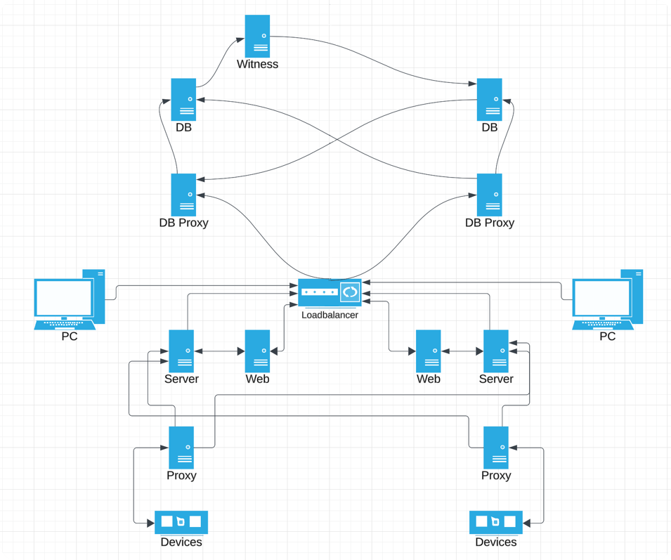
Zabbix proxy was deployed in the Columbus module alongside other software required for research, operations, and connectivity. The Zabbix server and frontend are deployed in the ground data center, and this is what the proxy communicates with.

In addition to proxies, we have a Zabbix sender and Agent 2 that are used on this infrastructure, which is made of VMS and containers running different kinds of services. Data is collected in a very ordinary fashion – Zabbix Agent 2 performs native checks because there is still server hardware running with operating systems and OS level resources that need to be monitored by the Agent.

We mix these native checks with user parameters which execute custom checks based on scripts or commands for commercial off-the-shelf components. The agent is extended depending on the requirements of the components. It then collects those metrics and sends them to the proxy. Scripting is used for custom components, and because Zabbix is language agnostic, any type of programming or scripting language works. It gets wrapped together with Zabbix sender, which then sends data to the proxy, which then sends data to the server.

Because there are so many custom services and metrics that need to be monitored (the number of high priority files in the transfer queue for a particular payload, for example) and because metrics, services, and payloads can change over time, the ESA needed to automate a way of automatically discovering these, displaying them, and collecting data for them. We used low-level discovery together with some scripting to discover and automatically start monitoring new payloads.

The results

Thanks to Zabbix’s visualization capabilities, the ESA’s team has found it easy to observe their dashboards and react to alerts in real time.

The ESA has also found Zabbix proxy to be an ideal solution for their needs, because if a link between the ground data center and the Columbus module goes down, the proxy keeps collecting local metrics, stores them in its own database, and then sends them back to the ground once the connection is restored. No such situation has arisen yet, but Zabbix has performed flawlessly in all test scenarios.

Monitoring is a never-ending process and there’s always room for improvement, but it’s reasonable to expect that the ESA will continue working on Zabbix and finding new metrics and new ways of improving monitoring.

In conclusion

Part of the beauty of Zabbix has always been its adaptability – it can be as simple or as complex as any user needs it to be. The simplicity of the Zabbix setup in this scenario (as opposed to a more modular setup with 4 or 5 pieces of software) is what makes it ideal for deployment by the ESA on the International Space Station.

To learn more about what we do for customers across multiple industries, visit our website or request a demo.

The post Case Study: Zabbix at the European Space Agency appeared first on Zabbix Blog.

How the GoDaddy data platform achieved over 60% cost reduction and 50% performance boost by adopting Amazon EMR Serverless

Post Syndicated from Brandon Abear original https://aws.amazon.com/blogs/big-data/how-the-godaddy-data-platform-achieved-over-60-cost-reduction-and-50-performance-boost-by-adopting-amazon-emr-serverless/

This is a guest post co-written with Brandon Abear, Dinesh Sharma, John Bush, and Ozcan IIikhan from GoDaddy.

GoDaddy empowers everyday entrepreneurs by providing all the help and tools to succeed online. With more than 20 million customers worldwide, GoDaddy is the place people come to name their ideas, build a professional website, attract customers, and manage their work.

At GoDaddy, we take pride in being a data-driven company. Our relentless pursuit of valuable insights from data fuels our business decisions and ensures customer satisfaction. Our commitment to efficiency is unwavering, and we’ve undertaken an exciting initiative to optimize our batch processing jobs. In this journey, we have identified a structured approach that we refer to as the seven layers of improvement opportunities. This methodology has become our guide in the pursuit of efficiency.

In this post, we discuss how we enhanced operational efficiency with Amazon EMR Serverless. We share our benchmarking results and methodology, and insights into the cost-effectiveness of EMR Serverless vs. fixed capacity Amazon EMR on EC2 transient clusters on our data workflows orchestrated using Amazon Managed Workflows for Apache Airflow (Amazon MWAA). We share our strategy for the adoption of EMR Serverless in areas where it excels. Our findings reveal significant benefits, including over 60% cost reduction, 50% faster Spark workloads, a remarkable five-times improvement in development and testing speed, and a significant reduction in our carbon footprint.

Background

In late 2020, GoDaddy’s data platform initiated its AWS Cloud journey, migrating an 800-node Hadoop cluster with 2.5 PB of data from its data center to EMR on EC2. This lift-and-shift approach facilitated a direct comparison between on-premises and cloud environments, ensuring a smooth transition to AWS pipelines, minimizing data validation issues and migration delays.

By early 2022, we successfully migrated our big data workloads to EMR on EC2. Using best practices learned from the AWS FinHack program, we fine-tuned resource-intensive jobs, converted Pig and Hive jobs to Spark, and reduced our batch workload spend by 22.75% in 2022. However, scalability challenges emerged due to the multitude of jobs. This prompted GoDaddy to embark on a systematic optimization journey, establishing a foundation for more sustainable and efficient big data processing.

Seven layers of improvement opportunities

In our quest for operational efficiency, we have identified seven distinct layers of opportunities for optimization within our batch processing jobs, as shown in the following figure. These layers range from precise code-level enhancements to more comprehensive platform improvements. This multi-layered approach has become our strategic blueprint in the ongoing pursuit of better performance and higher efficiency.

Seven layers of improvement opportunities

The layers are as follows:

  • Code optimization – Focuses on refining the code logic and how it can be optimized for better performance. This involves performance enhancements through selective caching, partition and projection pruning, join optimizations, and other job-specific tuning. Using AI coding solutions is also an integral part of this process.
  • Software updates – Updating to the latest versions of open source software (OSS) to capitalize on new features and improvements. For example, Adaptive Query Execution in Spark 3 brings significant performance and cost improvements.
  • Custom Spark configurations Tuning of custom Spark configurations to maximize resource utilization, memory, and parallelism. We can achieve significant improvements by right-sizing tasks, such as through spark.sql.shuffle.partitions, spark.sql.files.maxPartitionBytes, spark.executor.cores, and spark.executor.memory. However, these custom configurations might be counterproductive if they are not compatible with the specific Spark version.
  • Resource provisioning time The time it takes to launch resources like ephemeral EMR clusters on Amazon Elastic Compute Cloud (Amazon EC2). Although some factors influencing this time are outside of an engineer’s control, identifying and addressing the factors that can be optimized can help reduce overall provisioning time.
  • Fine-grained scaling at task level Dynamically adjusting resources such as CPU, memory, disk, and network bandwidth based on each stage’s needs within a task. The aim here is to avoid fixed cluster sizes that could result in resource waste.
  • Fine-grained scaling across multiple tasks in a workflow Given that each task has unique resource requirements, maintaining a fixed resource size may result in under- or over-provisioning for certain tasks within the same workflow. Traditionally, the size of the largest task determines the cluster size for a multi-task workflow. However, dynamically adjusting resources across multiple tasks and steps within a workflow result in a more cost-effective implementation.
  • Platform-level enhancements – Enhancements at preceding layers can only optimize a given job or a workflow. Platform improvement aims to attain efficiency at the company level. We can achieve this through various means, such as updating or upgrading the core infrastructure, introducing new frameworks, allocating appropriate resources for each job profile, balancing service usage, optimizing the use of Savings Plans and Spot Instances, or implementing other comprehensive changes to boost efficiency across all tasks and workflows.

Layers 1–3: Previous cost reductions

After we migrated from on premises to AWS Cloud, we primarily focused our cost-optimization efforts on the first three layers shown in the diagram. By transitioning our most costly legacy Pig and Hive pipelines to Spark and optimizing Spark configurations for Amazon EMR, we achieved significant cost savings.

For example, a legacy Pig job took 10 hours to complete and ranked among the top 10 most expensive EMR jobs. Upon reviewing TEZ logs and cluster metrics, we discovered that the cluster was vastly over-provisioned for the data volume being processed and remained under-utilized for most of the runtime. Transitioning from Pig to Spark was more efficient. Although no automated tools were available for the conversion, manual optimizations were made, including:

  • Reduced unnecessary disk writes, saving serialization and deserialization time (Layer 1)
  • Replaced Airflow task parallelization with Spark, simplifying the Airflow DAG (Layer 1)
  • Eliminated redundant Spark transformations (Layer 1)
  • Upgraded from Spark 2 to 3, using Adaptive Query Execution (Layer 2)
  • Addressed skewed joins and optimized smaller dimension tables (Layer 3)

As a result, job cost decreased by 95%, and job completion time was reduced to 1 hour. However, this approach was labor-intensive and not scalable for numerous jobs.

Layers 4–6: Find and adopt the right compute solution

In late 2022, following our significant accomplishments in optimization at the previous levels, our attention moved towards enhancing the remaining layers.

Understanding the state of our batch processing

We use Amazon MWAA to orchestrate our data workflows in the cloud at scale. Apache Airflow is an open source tool used to programmatically author, schedule, and monitor sequences of processes and tasks referred to as workflows. In this post, the terms workflow and job are used interchangeably, referring to the Directed Acyclic Graphs (DAGs) consisting of tasks orchestrated by Amazon MWAA. For each workflow, we have sequential or parallel tasks, and even a combination of both in the DAG between create_emr and terminate_emr tasks running on a transient EMR cluster with fixed compute capacity throughout the workflow run. Even after optimizing a portion of our workload, we still had numerous non-optimized workflows that were under-utilized due to over-provisioning of compute resources based on the most resource-intensive task in the workflow, as shown in the following figure.

This highlighted the impracticality of static resource allocation and led us to recognize the necessity of a dynamic resource allocation (DRA) system. Before proposing a solution, we gathered extensive data to thoroughly understand our batch processing. Analyzing the cluster step time, excluding provisioning and idle time, revealed significant insights: a right-skewed distribution with over half of the workflows completing in 20 minutes or less and only 10% taking more than 60 minutes. This distribution guided our choice of a fast-provisioning compute solution, dramatically reducing workflow runtimes. The following diagram illustrates step times (excluding provisioning and idle time) of EMR on EC2 transient clusters in one of our batch processing accounts.

Furthermore, based on the step time (excluding provisioning and idle time) distribution of the workflows, we categorized our workflows into three groups:

  • Quick run – Lasting 20 minutes or less
  • Medium run – Lasting between 20–60 minutes
  • Long run – Exceeding 60 minutes, often spanning several hours or more

Another factor we needed to consider was the extensive use of transient clusters for reasons such as security, job and cost isolation, and purpose-built clusters. Additionally, there was a significant variation in resource needs between peak hours and periods of low utilization.

Instead of fixed-size clusters, we could potentially use managed scaling on EMR on EC2 to achieve some cost benefits. However, migrating to EMR Serverless appears to be a more strategic direction for our data platform. In addition to potential cost benefits, EMR Serverless offers additional advantages such as a one-click upgrade to the newest Amazon EMR versions, a simplified operational and debugging experience, and automatic upgrades to the latest generations upon rollout. These features collectively simplify the process of operating a platform on a larger scale.

Evaluating EMR Serverless: A case study at GoDaddy

EMR Serverless is a serverless option in Amazon EMR that eliminates the complexities of configuring, managing, and scaling clusters when running big data frameworks like Apache Spark and Apache Hive. With EMR Serverless, businesses can enjoy numerous benefits, including cost-effectiveness, faster provisioning, simplified developer experience, and improved resilience to Availability Zone failures.

Recognizing the potential of EMR Serverless, we conducted an in-depth benchmark study using real production workflows. The study aimed to assess EMR Serverless performance and efficiency while also creating an adoption plan for large-scale implementation. The findings were highly encouraging, showing EMR Serverless can effectively handle our workloads.

Benchmarking methodology

We split our data workflows into three categories based on total step time (excluding provisioning and idle time): quick run (0–20 minutes), medium run (20–60 minutes), and long run (over 60 minutes). We analyzed the impact of the EMR deployment type (Amazon EC2 vs. EMR Serverless) on two key metrics: cost-efficiency and total runtime speedup, which served as our overall evaluation criteria. Although we did not formally measure ease of use and resiliency, these factors were considered throughout the evaluation process.

The high-level steps to assess the environment are as follows:

  1. Prepare the data and environment:
    1. Choose three to five random production jobs from each job category.
    2. Implement required adjustments to prevent interference with production.
  2. Run tests:
    1. Run scripts over several days or through multiple iterations to gather precise and consistent data points.
    2. Perform tests using EMR on EC2 and EMR Serverless.
  3. Validate data and test runs:
    1. Validate input and output datasets, partitions, and row counts to ensure identical data processing.
  4. Gather metrics and analyze results:
    1. Gather relevant metrics from the tests.
    2. Analyze results to draw insights and conclusions.

Benchmark results

Our benchmark results showed significant enhancements across all three job categories for both runtime speedup and cost-efficiency. The improvements were most pronounced for quick jobs, directly resulting from faster startup times. For instance, a 20-minute (including cluster provisioning and shut down) data workflow running on an EMR on EC2 transient cluster of fixed compute capacity finishes in 10 minutes on EMR Serverless, providing a shorter runtime with cost benefits. Overall, the shift to EMR Serverless delivered substantial performance improvements and cost reductions at scale across job brackets, as seen in the following figure.

Historically, we devoted more time to tuning our long-run workflows. Interestingly, we discovered that the existing custom Spark configurations for these jobs did not always translate well to EMR Serverless. In cases where the results were insignificant, a common approach was to discard previous Spark configurations related to executor cores. By allowing EMR Serverless to autonomously manage these Spark configurations, we often observed improved outcomes. The following graph shows the average runtime and cost improvement per job when comparing EMR Serverless to EMR on EC2.

Per Job Improvement

The following table shows a sample comparison of results for the same workflow running on different deployment options of Amazon EMR (EMR on EC2 and EMR Serverless).

Metric EMR on EC2
(Average)
EMR Serverless
(Average)
EMR on EC2 vs
EMR Serverless
Total Run Cost ($) $ 5.82 $ 2.60 55%
Total Run Time (Minutes) 53.40 39.40 26%
Provisioning Time (Minutes) 10.20 0.05 .
Provisioning Cost ($) $ 1.19 . .
Steps Time (Minutes) 38.20 39.16 -3%
Steps Cost ($) $ 4.30 . .
Idle Time (Minutes) 4.80 . .
EMR Release Label emr-6.9.0 .
Hadoop Distribution Amazon 3.3.3 .
Spark Version Spark 3.3.0 .
Hive/HCatalog Version Hive 3.1.3, HCatalog 3.1.3 .
Job Type Spark .

AWS Graviton2 on EMR Serverless performance evaluation

After seeing compelling results with EMR Serverless for our workloads, we decided to further analyze the performance of the AWS Graviton2 (arm64) architecture within EMR Serverless. AWS had benchmarked Spark workloads on Graviton2 EMR Serverless using the TPC-DS 3TB scale, showing a 27% overall price-performance improvement.

To better understand the integration benefits, we ran our own study using GoDaddy’s production workloads on a daily schedule and observed an impressive 23.8% price-performance enhancement across a range of jobs when using Graviton2. For more details about this study, see GoDaddy benchmarking results in up to 24% better price-performance for their Spark workloads with AWS Graviton2 on Amazon EMR Serverless.

Adoption strategy for EMR Serverless

We strategically implemented a phased rollout of EMR Serverless via deployment rings, enabling systematic integration. This gradual approach let us validate improvements and halt further adoption of EMR Serverless, if needed. It served both as a safety net to catch issues early and a means to refine our infrastructure. The process mitigated change impact through smooth operations while building team expertise of our Data Engineering and DevOps teams. Additionally, it fostered tight feedback loops, allowing prompt adjustments and ensuring efficient EMR Serverless integration.

We divided our workflows into three main adoption groups, as shown in the following image:

  • Canaries This group aids in detecting and resolving any potential problems early in the deployment stage.
  • Early adopters This is the second batch of workflows that adopt the new compute solution after initial issues have been identified and rectified by the canaries group.
  • Broad deployment rings The largest group of rings, this group represents the wide-scale deployment of the solution. These are deployed after successful testing and implementation in the previous two groups.

Rings

We further broke down these workflows into granular deployment rings to adopt EMR Serverless, as shown in the following table.

Ring # Name Details
Ring 0 Canary Low adoption risk jobs that are expected to yield some cost saving benefits.
Ring 1 Early Adopters Low risk Quick-run Spark jobs that expect to yield high gains.
Ring 2 Quick-run Rest of the Quick-run (step_time <= 20 min) Spark jobs
Ring 3 LargerJobs_EZ High potential gain, easy move, medium-run and long-run Spark jobs
Ring 4 LargerJobs Rest of the medium-run and long-run Spark jobs with potential gains
Ring 5 Hive Hive jobs with potentially higher cost savings
Ring 6 Redshift_EZ Easy migration Redshift jobs that suit EMR Serverless
Ring 7 Glue_EZ Easy migration Glue jobs that suit EMR Serverless

Production adoption results summary

The encouraging benchmarking and canary adoption results generated considerable interest in wider EMR Serverless adoption at GoDaddy. To date, the EMR Serverless rollout remains underway. Thus far, it has reduced costs by 62.5% and accelerated total batch workflow completion by 50.4%.

Based on preliminary benchmarks, our team expected substantial gains for quick jobs. To our surprise, actual production deployments surpassed projections, averaging 64.4% faster vs. 42% projected, and 71.8% cheaper vs. 40% predicted.

Remarkably, long-running jobs also saw significant performance improvements due to the rapid provisioning of EMR Serverless and aggressive scaling enabled by dynamic resource allocation. We observed substantial parallelization during high-resource segments, resulting in a 40.5% faster total runtime compared to traditional approaches. The following chart illustrates the average enhancements per job category.

Prod Jobs Savings

Additionally, we observed the highest degree of dispersion for speed improvements within the long-run job category, as shown in the following box-and-whisker plot.

Whisker Plot

Sample workflows adopted EMR Serverless

For a large workflow migrated to EMR Serverless, comparing 3-week averages pre- and post-migration revealed impressive cost savings—a 75.30% decrease based on retail pricing with 10% improvement in total runtime, boosting operational efficiency. The following graph illustrates the cost trend.

Although quick-run jobs realized minimal per-dollar cost reductions, they delivered the most significant percentage cost savings. With thousands of these workflows running daily, the accumulated savings are substantial. The following graph shows the cost trend for a small workload migrated from EMR on EC2 to EMR Serverless. Comparing 3-week pre- and post-migration averages revealed a remarkable 92.43% cost savings on the retail on-demand pricing, alongside an 80.6% acceleration in total runtime.

Sample workflows adopted EMR Serverless 2

Layer 7: Platform-wide improvements

We aim to revolutionize compute operations at GoDaddy, providing simplified yet powerful solutions for all users with our Intelligent Compute Platform. With AWS compute solutions like EMR Serverless and EMR on EC2, it provided optimized runs of data processing and machine learning (ML) workloads. An ML-powered job broker intelligently determines when and how to run jobs based on various parameters, while still allowing power users to customize. Additionally, an ML-powered compute resource manager pre-provisions resources based on load and historical data, providing efficient, fast provisioning at optimum cost. Intelligent compute empowers users with out-of-the-box optimization, catering to diverse personas without compromising power users.

The following diagram shows a high-level illustration of the intelligent compute architecture.

Insights and recommended best-practices

The following section discusses the insights we’ve gathered and the recommended best practices we’ve developed during our preliminary and wider adoption stages.

Infrastructure preparation

Although EMR Serverless is a deployment method within EMR, it requires some infrastructure preparedness to optimize its potential. Consider the following requirements and practical guidance on implementation:

  • Use large subnets across multiple Availability Zones – When running EMR Serverless workloads within your VPC, make sure the subnets span across multiple Availability Zones and are not constrained by IP addresses. Refer to Configuring VPC access and Best practices for subnet planning for details.
  • Modify maximum concurrent vCPU quota For extensive compute requirements, it is recommended to increase your max concurrent vCPUs per account service quota.
  • Amazon MWAA version compatibility When adopting EMR Serverless, GoDaddy’s decentralized Amazon MWAA ecosystem for data pipeline orchestration created compatibility issues from disparate AWS Providers versions. Directly upgrading Amazon MWAA was more efficient than updating numerous DAGs. We facilitated adoption by upgrading Amazon MWAA instances ourselves, documenting issues, and sharing findings and effort estimates for accurate upgrade planning.
  • GoDaddy EMR operator To streamline migrating numerous Airflow DAGs from EMR on EC2 to EMR Serverless, we developed custom operators adapting existing interfaces. This allowed seamless transitions while retaining familiar tuning options. Data engineers could easily migrate pipelines with simple find-replace imports and immediately use EMR Serverless.

Unexpected behavior mitigation

The following are unexpected behaviors we ran into and what we did to mitigate them:

  • Spark DRA aggressive scaling For some jobs (8.33% of initial benchmarks, 13.6% of production), cost increased after migrating to EMR Serverless. This was due to Spark DRA excessively assigning new workers briefly, prioritizing performance over cost. To counteract this, we set maximum executor thresholds by adjusting spark.dynamicAllocation.maxExecutor, effectively limiting EMR Serverless scaling aggression. When migrating from EMR on EC2, we suggest observing the max core count in the Spark History UI to replicate similar compute limits in EMR Serverless, such as --conf spark.executor.cores and --conf spark.dynamicAllocation.maxExecutors.
  • Managing disk space for large-scale jobs When transitioning jobs that process large data volumes with substantial shuffles and significant disk requirements to EMR Serverless, we recommend configuring spark.emr-serverless.executor.disk by referring to existing Spark job metrics. Furthermore, configurations like spark.executor.cores combined with spark.emr-serverless.executor.disk and spark.dynamicAllocation.maxExecutors allow control over the underlying worker size and total attached storage when advantageous. For example, a shuffle-heavy job with relatively low disk usage may benefit from using a larger worker to increase the likelihood of local shuffle fetches.

Conclusion

As discussed in this post, our experiences with adopting EMR Serverless on arm64 have been overwhelmingly positive. The impressive results we’ve achieved, including a 60% reduction in cost, 50% faster runs of batch Spark workloads, and an astounding five-times improvement in development and testing speed, speak volumes about the potential of this technology. Furthermore, our current results suggest that by widely adopting Graviton2 on EMR Serverless, we could potentially reduce the carbon footprint by up to 60% for our batch processing.

However, it’s crucial to understand that these results are not a one-size-fits-all scenario. The enhancements you can expect are subject to factors including, but not limited to, the specific nature of your workflows, cluster configurations, resource utilization levels, and fluctuations in computational capacity. Therefore, we strongly advocate for a data-driven, ring-based deployment strategy when considering the integration of EMR Serverless, which can help optimize its benefits to the fullest.

Special thanks to Mukul Sharma and Boris Berlin for their contributions to benchmarking. Many thanks to Travis Muhlestein (CDO), Abhijit Kundu (VP Eng), Vincent Yung (Sr. Director Eng.), and Wai Kin Lau (Sr. Director Data Eng.) for their continued support.


About the Authors

Brandon Abear is a Principal Data Engineer in the Data & Analytics (DnA) organization at GoDaddy. He enjoys all things big data. In his spare time, he enjoys traveling, watching movies, and playing rhythm games.

Dinesh Sharma is a Principal Data Engineer in the Data & Analytics (DnA) organization at GoDaddy. He is passionate about user experience and developer productivity, always looking for ways to optimize engineering processes and saving cost. In his spare time, he loves reading and is an avid manga fan.

John Bush is a Principal Software Engineer in the Data & Analytics (DnA) organization at GoDaddy. He is passionate about making it easier for organizations to manage data and use it to drive their businesses forward. In his spare time, he loves hiking, camping, and riding his ebike.

Ozcan Ilikhan is the Director of Engineering for the Data and ML Platform at GoDaddy. He has over two decades of multidisciplinary leadership experience, spanning startups to global enterprises. He has a passion for leveraging data and AI in creating solutions that delight customers, empower them to achieve more, and boost operational efficiency. Outside of his professional life, he enjoys reading, hiking, gardening, volunteering, and embarking on DIY projects.

Harsh Vardhan is an AWS Solutions Architect, specializing in big data and analytics. He has over 8 years of experience working in the field of big data and data science. He is passionate about helping customers adopt best practices and discover insights from their data.
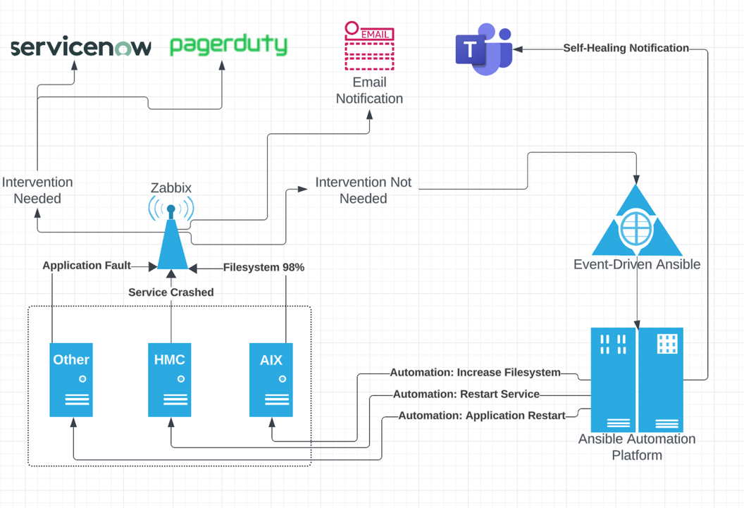
Case of success: phygital environment monitoring with Zabbix

Post Syndicated from Aurea Araujo original https://blog.zabbix.com/case-of-success-phygital-environment-monitoring-with-zabbix/27108/

When retail needs involve monitoring diverse and complex environments, with digital and physical operations, the tool chosen to meet those needs must be versatile, scalable and capable of collecting and analyzing data to generate insights for managers and support decision-making.

With this in mind, Unirede – a Zabbix Premium Partner – developed a use case consisting of monitoring a client in the retail segment, using Zabbix as the main tool for data collection, consolidation and event management.

The result: a reduction of up to 70% in operational costs and other benefits related to data-based decision-making, following the data driven concept and automation at the technological environment level for rapid responses to incidents.

Continue reading to understand, in detail, how monitoring can support retail needs, based on this case of success.

Retail needs

Currently, stores and brands that offer an omnichannel experience are standing out in the market. This means that they are available 24 hours a day, 7 days a week, not only in physical spaces (such as the stores themselves), but also digitally (through e-commerce and mobile app operations). These retailers also have critical operations in distribution centers that operate without interruption.

As a result, the environment to be monitored becomes what we call phygital – both physical and digital, at the same time. This is a concept the origins of which are closely linked to the Internet and global digitalization.

With this, customers can choose to buy from home, on their cell phone, wherever they are. However, if necessary, they can find the support they need in physical stores, with the same rules and prices across all channels.

Therefore, retailers need to ensure that the operation is able to deliver, full-time, a consistent customer experience on any channel, mitigating or preventing unavailability and loss of service performance. Additionally, they need to provide support to requests for help that may arise from managers who are responsible for the company’s results.

And this is not limited to just one type of retail. Segments such as supermarkets, fast fashion, specialists, fast food and pharmaceutical, among others, can benefit from data monitoring to improve the work carried out in activities such as:

  • Understanding the purchasing journey of omnibuyer customers (on-line/off-line):
  • Complete monitoring of user experience;
  • Maximizing the operation of distribution centers;
  • Monitoring points of sale (POS);
  • Developing technical and executive dashboardswith the main KPIs of the business;
  • Reports with information for making decisions in real time.

So, through monitoring with Zabbix, it is possible to collect data from different points, organize these data as information in visual dashboards and generate knowledge to improve internal and external customer service from end to end.

How monitoring with Zabbix works

We talk about the benefits and needs regarding retailers, but we also need to explain how monitoring with Zabbix works in this type of environment.

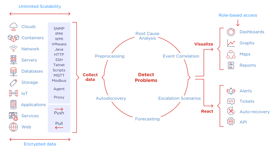
Beginning with the basics: Zabbix collects, categorizes, analyzes and generates information from data.

This process divided into 4 stages:

  • Data collection;
  • Problem detection;
  • Visualization;
  • Reaction.
Zabbix activity cycle

In the first stage, Zabbix captures data from different sources, which can be cloud systems, containers, networks, servers, databases, APIs, stocks, payment methods, applications, services and the Internet of Things. At this stage, there is a lot of flexibility in the tool itself, and it is also possible to create completely customized collection methods.

The data are encrypted, as Zabbix follows the premise of Security by Design, and they are analyzed in a processing stage to detect possible problems or behaviors that the business wants to be detected.

At this stage, data processing categorizes information into events by severity, indicates the root cause of the potential problem or anomaly, correlates these events based on predefinitions established by system administrators or business managers, begins self-remediation of this problem, and creates predictions based on metrics behaviors so that the business is ready and prepared to deal with events that have not yet occurred.

Afterwards, the information generated is allocated to dashboards for better visualization and, consequently, administrators choose how to react to what is shown.

Reactions can take the form of alerts via message, e-mail and applications, by generating tickets to the support team, by establishing a connection to other applications and systems, and by automating problem solving – or self-healing.

Main on-line and off-line retail indicators

By monitoring systems and the main resources of the retail environment, in addition to ensuring better availability and performance, it is possible to extract critical indicators for your business in real time.

There are indicators that are found both in physical and digital retail operations. With Zabbix, it is possible to collect and measure each one of these indicators, such as:

  • Gross sales;
  • Average ticket;
  • Sales by product category;
  • Sales by payment method;
  • Number of sales;
  • Accumulated sales in a given period;
  • Inventory value;
  • Sales by M2;
  • Sales by collaborator;
  • Year-over-Year Sales (YoY);
  • Goals achieved;
  • Conversion rate (from visitor to customer);
  • Traffic origin channels;
  • Time spent in e-commerce;
  • New visitors vs. returning visitors;
  • Cart abandonment.

By analyzing the elements mentioned above, also through monitoring, it is possible to understand how the performance of on-line sales is compared to off-line sales, helping business owners to make a decision on which of the means – or all of them – should receive more or less investments to generate more revenue.

We mentioned automating manual processes not long ago.

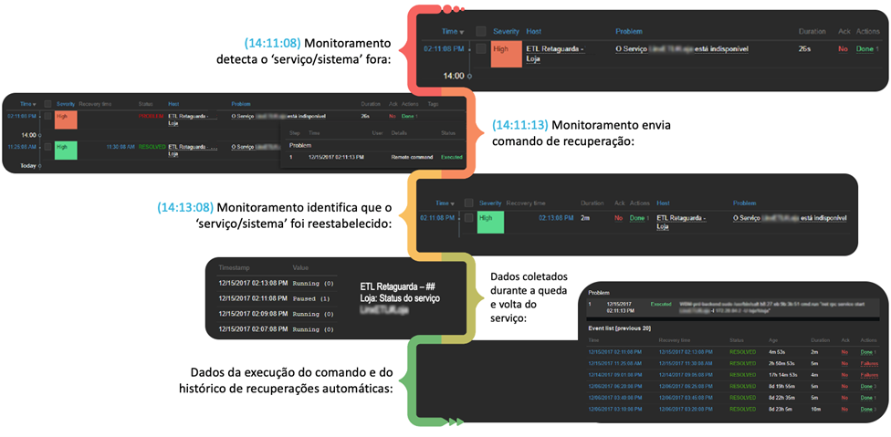
In retail, this can happen with the discovery of events and the indication of root causes, such as identifying the unavailability of a service or component that impacts the proper operation of a given system and, based on rules defined in Zabbix, triggering a self-recovery command, without human intervention, as in the following example:

Example of self-healing with Zabbix, used by Unirede.

What are the benefits of monitoring for retailers?

How can monitoring become essential for the digital transformation of retailers?

In order to do this, we need to understand the benefits of collecting and analyzing data with Zabbix.

The first and most objective one is the monitoring of support services, both in physical and digital operations. Here, we are talking about networks, connections, and IT infrastructure in general.

But there is also monitoring distribution centers in order to optimize supply chains, and capturing data from stores, points of sale, data centers and clouds.

With this duly adjusted, we move on to how the monitoring and sustainment of basic services helps retailers to have a better view of environments, analyzing performance indicators in real time and managing SLAs.

The result of a monitoring system with Zabbix in retail is having operations focused on customer experience, ensuring cost reductions and gains in operational efficiency.

Lessons learned from retailer monitoring

With so many possibilities and advantages resulting from using Zabbix in retail, it is difficult to choose where to start.

We need to bear in mind that, when implementing Zabbix in this area, it is important to focus on what is essential, that is, monitoring only what is necessary, instead of monitoring data that will not result in any type of action or analysis in case of an event. Avoid standard templates without the necessary adjustments to meet the specificities of your environment and the analysis practices your business requires..

Automating as much as possible is also a crucial practice, as it allows the team to dedicate more time to strategic activities in the area, thus spending less time dealing with incidents and adding new hosts.

And, of course, even if it is possible to have an integration with other tools, it is worth carrying out a thorough review of existing monitoring efforts in other tools to avoid generating events that are irrelevant, that is, that do not require any type of action by the team. This approach ensures that integration is smooth and does not compromise the effectiveness of the system and operations by generating excessive or unnecessary events.

Last but not least: it is important to recognize the essential and crucial role of the people who use the tool. They not only operate Zabbix, but also play an active role in the development and continuous evolution of business monitoring efforts.

By giving these users a voice and promoting training sessions, your company can invest in more meaningful collaborations, contributing to the continuous adaptation of Zabbix to the specific needs of the retail segment.

About Unirede

Unirede is a technology company, with roots in the State of Rio Grande do Sul and headquartered in Porto Alegre. It was created in 1999 and is dedicated to provide its clients with effective consulting services to improve business performance. Its activities aim to increase productivity, minimize downtime and drive the integration of technological innovations through managed services.

With a philosophy centered on simplicity, Unirede focuses on human relationships, both internally and with clients. There is a conscious effort to not only provide services, but also to establish relationships, favoring the delivery of intelligent solutions that add value to clients.

Unirede has achieved a level of excellence and commitment to results that has resulted in the establishment of strategic partnerships with technology market leaders. It stands out as the first Zabbix Premium Partner in Latin America, since 2008, and was the first Zabbix Training Partner in the world, in 2012.

Find out more about the Official Zabbix Partner Program.

The post Case of success: phygital environment monitoring with Zabbix appeared first on Zabbix Blog.

How Zoom implemented streaming log ingestion and efficient GDPR deletes using Apache Hudi on Amazon EMR

Post Syndicated from Sekar Srinivasan original https://aws.amazon.com/blogs/big-data/how-zoom-implemented-streaming-log-ingestion-and-efficient-gdpr-deletes-using-apache-hudi-on-amazon-emr/

In today’s digital age, logging is a critical aspect of application development and management, but efficiently managing logs while complying with data protection regulations can be a significant challenge. Zoom, in collaboration with the AWS Data Lab team, developed an innovative architecture to overcome these challenges and streamline their logging and record deletion processes. In this post, we explore the architecture and the benefits it provides for Zoom and its users.

Application log challenges: Data management and compliance

Application logs are an essential component of any application; they provide valuable information about the usage and performance of the system. These logs are used for a variety of purposes, such as debugging, auditing, performance monitoring, business intelligence, system maintenance, and security. However, although these application logs are necessary for maintaining and improving the application, they also pose an interesting challenge. These application logs may contain personally identifiable data, such as user names, email addresses, IP addresses, and browsing history, which creates a data privacy concern.

Laws such as the General Data Protection Regulation (GDPR) and the California Consumer Privacy Act (CCPA) require organizations to retain application logs for a specific period of time. The exact length of time required for data storage varies depending on the specific regulation and the type of data being stored. The reason for these data retention periods is to ensure that companies aren’t keeping personal data longer than necessary, which could increase the risk of data breaches and other security incidents. This also helps ensure that companies aren’t using personal data for purposes other than those for which it was collected, which could be a violation of privacy laws. These laws also give individuals the right to request the deletion of their personal data, also known as the “right to be forgotten.” Individuals have the right to have their personal data erased, without undue delay.

So, on one hand, organizations need to collect application log data to ensure the proper functioning of their services, and keep the data for a specific period of time. But on the other hand, they may receive requests from individuals to delete their personal data from the logs. This creates a balancing act for organizations because they must comply with both data retention and data deletion requirements.

This issue becomes increasingly challenging for larger organizations that operate in multiple countries and states, because each country and state may have their own rules and regulations regarding data retention and deletion. For example, the Personal Information Protection and Electronic Documents Act (PIPEDA) in Canada and the Australian Privacy Act in Australia are similar laws to GDPR, but they may have different retention periods or different exceptions. Therefore, organizations big or small must navigate this complex landscape of data retention and deletion requirements, while also ensuring that they are in compliance with all applicable laws and regulations.

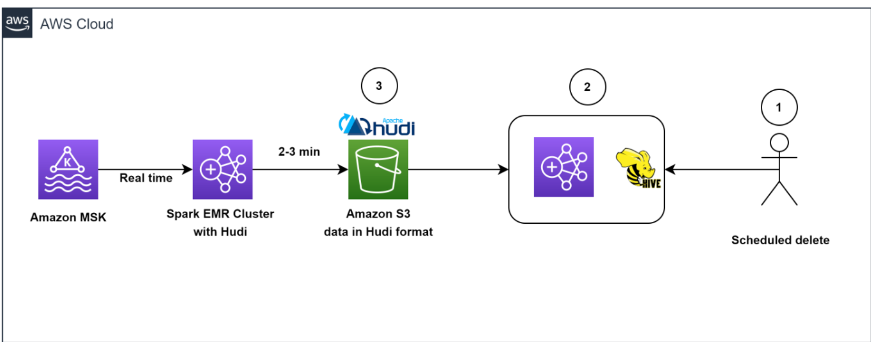
Zoom’s initial architecture

During the COVID-19 pandemic, the use of Zoom skyrocketed as more and more people were asked to work and attend classes from home. The company had to rapidly scale its services to accommodate the surge and worked with AWS to deploy capacity across most Regions globally. With a sudden increase in the large number of application endpoints, they had to rapidly evolve their log analytics architecture and worked with the AWS Data Lab team to quickly prototype and deploy an architecture for their compliance use case.

At Zoom, the data ingestion throughput and performance needs are very stringent. Data had to be ingested from several thousand application endpoints that produced over 30 million messages every minute, resulting in over 100 TB of log data per day. The existing ingestion pipeline consisted of writing the data to Apache Hadoop HDFS storage through Apache Kafka first and then running daily jobs to move the data to persistent storage. This took several hours while also slowing the ingestion and creating the potential for data loss. Scaling the architecture was also an issue because HDFS data would have to be moved around whenever nodes were added or removed. Furthermore, transactional semantics on billions of records were necessary to help meet compliance-related data delete requests, and the existing architecture of daily batch jobs was operationally inefficient.

It was at this time, through conversations with the AWS account team, that the AWS Data Lab team got involved to assist in building a solution for Zoom’s hyper-scale.

Solution overview

The AWS Data Lab offers accelerated, joint engineering engagements between customers and AWS technical resources to create tangible deliverables that accelerate data, analytics, artificial intelligence (AI), machine learning (ML), serverless, and container modernization initiatives. The Data Lab has three offerings: the Build Lab, the Design Lab, and Resident Architect. During the Build and Design Labs, AWS Data Lab Solutions Architects and AWS experts supported Zoom specifically by providing prescriptive architectural guidance, sharing best practices, building a working prototype, and removing technical roadblocks to help meet their production needs.

Zoom and the AWS team (collectively referred to as “the team” going forward) identified two major workflows for data ingestion and deletion.

Data ingestion workflow

The following diagram illustrates the data ingestion workflow.

Data Ingestion Workflow

The team needed to quickly populate millions of Kafka messages in the dev/test environment to achieve this. To expedite the process, we (the team) opted to use Amazon Managed Streaming for Apache Kafka (Amazon MSK), which makes it simple to ingest and process streaming data in real time, and we were up and running in under a day.

To generate test data that resembled production data, the AWS Data Lab team created a custom Python script that evenly populated over 1.2 billion messages across several Kafka partitions. To match the production setup in the development account, we had to increase the cloud quota limit via a support ticket.

We used Amazon MSK and the Spark Structured Streaming capability in Amazon EMR to ingest and process the incoming Kafka messages with high throughput and low latency. Specifically, we inserted the data from the source into EMR clusters at a maximum incoming rate of 150 million Kafka messages every 5 minutes, with each Kafka message holding 7–25 log data records.

To store the data, we chose to use Apache Hudi as the table format. We opted for Hudi because it’s an open-source data management framework that provides record-level insert, update, and delete capabilities on top of an immutable storage layer like Amazon Simple Storage Service (Amazon S3). Additionally, Hudi is optimized for handling large datasets and works well with Spark Structured Streaming, which was already being used at Zoom.

After 150 million messages were buffered, we processed the messages using Spark Structured Streaming on Amazon EMR and wrote the data into Amazon S3 in Apache Hudi-compatible format every 5 minutes. We first flattened the message array, creating a single record from the nested array of messages. Then we added a unique key, known as the Hudi record key, to each message. This key allows Hudi to perform record-level insert, update, and delete operations on the data. We also extracted the field values, including the Hudi partition keys, from incoming messages.

This architecture allowed end-users to query the data stored in Amazon S3 using Amazon Athena with the AWS Glue Data Catalog or using Apache Hive and Presto.

Data deletion workflow

The following diagram illustrates the data deletion workflow.

Data Deletion Workflow

Our architecture allowed for efficient data deletions. To help comply with the customer-initiated data retention policy for GDPR deletes, scheduled jobs ran daily to identify the data to be deleted in batch mode.

We then spun up a transient EMR cluster to run the GDPR upsert job to delete the records. The data was stored in Amazon S3 in Hudi format, and Hudi’s built-in index allowed us to efficiently delete records using bloom filters and file ranges. Because only those files that contained the record keys needed to be read and rewritten, it only took about 1–2 minutes to delete 1,000 records out of the 1 billion records, which had previously taken hours to complete as entire partitions were read.

Overall, our solution enabled efficient deletion of data, which provided an additional layer of data security that was critical for Zoom, in light of its GDPR requirements.

Architecting to optimize scale, performance, and cost

In this section, we share the following strategies Zoom took to optimize scale, performance, and cost:

  • Optimizing ingestion
  • Optimizing throughput and Amazon EMR utilization
  • Decoupling ingestion and GDPR deletion using EMRFS
  • Efficient deletes with Apache Hudi
  • Optimizing for low-latency reads with Apache Hudi
  • Monitoring

Optimizing ingestion

To keep the storage in Kafka lean and optimal, as well as to get a real-time view of data, we created a Spark job to read incoming Kafka messages in batches of 150 million messages and wrote to Amazon S3 in Hudi-compatible format every 5 minutes. Even during the initial stages of the iteration, when we hadn’t started scaling and tuning yet, we were able to successfully load all Kafka messages consistently under 2.5 minutes using the Amazon EMR runtime for Apache Spark.

Optimizing throughput and Amazon EMR utilization

We launched a cost-optimized EMR cluster and switched from uniform instance groups to using EMR instance fleets. We chose instance fleets because we needed the flexibility to use Spot Instances for task nodes and wanted to diversify the risk of running out of capacity for a specific instance type in our Availability Zone.

We started experimenting with test runs by first changing the number of Kafka partitions from 400 to 1,000, and then changing the number of task nodes and instance types. Based on the results of the run, the AWS team came up with the recommendation to use Amazon EMR with three core nodes (r5.16xlarge (64 vCPUs each)) and 18 task nodes using Spot fleet instances (a combination of r5.16xlarge (64 vCPUs), r5.12xlarge (48 vCPUs), r5.8xlarge (32 vCPUs)). These recommendations helped Zoom to reduce their Amazon EMR costs by more than 80% while meeting their desired performance goals of ingesting 150 million Kafka messages under 5 minutes.

Decoupling ingestion and GDPR deletion using EMRFS

A well-known benefit of separation of storage and compute is that you can scale the two independently. But a not-so-obvious advantage is that you can decouple continuous workloads from sporadic workloads. Previously data was stored in HDFS. Resource-intensive GDPR delete jobs and data movement jobs would compete for resources with the stream ingestion, causing a backlog of more than 5 hours in upstream Kafka clusters, which was close to filling up the Kafka storage (which only had 6 hours of data retention) and potentially causing data loss. Offloading data from HDFS to Amazon S3 allowed us the freedom to launch independent transient EMR clusters on demand to perform data deletion, helping to ensure that the ongoing data ingestion from Kafka into Amazon EMR is not starved for resources. This enabled the system to ingest data every 5 minutes and complete each Spark Streaming read in 2–3 minutes. Another side effect of using EMRFS is a cost-optimized cluster, because we removed reliance on Amazon Elastic Block Store (Amazon EBS) volumes for over 300 TB storage that was used for three copies (including two replicas) of HDFS data. We now pay for only one copy of the data in Amazon S3, which provides 11 9s of durability and is relatively inexpensive storage.

Efficient deletes with Apache Hudi

What about the conflict between ingest writes and GDPR deletes when running concurrently? This is where the power of Apache Hudi stands out.

Apache Hudi provides a table format for data lakes with transactional semantics that enables the separation of ingestion workloads and updates when run concurrently. The system was able to consistently delete 1,000 records in less than a minute. There were some limitations in concurrent writes in Apache Hudi 0.7.0, but the Amazon EMR team quickly addressed this by back-porting Apache Hudi 0.8.0, which supports optimistic concurrency control, to the current (at the time of the AWS Data Lab collaboration) Amazon EMR 6.4 release. This saved time in testing and allowed for a quick transition to the new version with minimal testing. This enabled us to query the data directly using Athena quickly without having to spin up a cluster to run ad hoc queries, as well as to query the data using Presto, Trino, and Hive. The decoupling of the storage and compute layers provided the flexibility to not only query data across different EMR clusters, but also delete data using a completely independent transient cluster.

Optimizing for low-latency reads with Apache Hudi

To optimize for low-latency reads with Apache Hudi, we needed to address the issue of too many small files being created within Amazon S3 due to the continuous streaming of data into the data lake.

We utilized Apache Hudi’s features to tune file sizes for optimal querying. Specifically, we reduced the degree of parallelism in Hudi from the default value of 1,500 to a lower number. Parallelism refers to the number of threads used to write data to Hudi; by reducing it, we were able to create larger files that were more optimal for querying.

Because we needed to optimize for high-volume streaming ingestion, we chose to implement the merge on read table type (instead of copy on write) for our workload. This table type allowed us to quickly ingest the incoming data into delta files in row format (Avro) and asynchronously compact the delta files into columnar Parquet files for fast reads. To do this, we ran the Hudi compaction job in the background. Compaction is the process of merging row-based delta files to produce new versions of columnar files. Because the compaction job would use additional compute resources, we adjusted the degree of parallelism for insertion to a lower value of 1,000 to account for the additional resource usage. This adjustment allowed us to create larger files without sacrificing performance throughput.

Overall, our approach to optimizing for low-latency reads with Apache Hudi allowed us to better manage file sizes and improve the overall performance of our data lake.

Monitoring

The team monitored MSK clusters with Prometheus (an open-source monitoring tool). Additionally, we showcased how to monitor Spark streaming jobs using Amazon CloudWatch metrics. For more information, refer to Monitor Spark streaming applications on Amazon EMR.

Outcomes

The collaboration between Zoom and the AWS Data Lab demonstrated significant improvements in data ingestion, processing, storage, and deletion using an architecture with Amazon EMR and Apache Hudi. One key benefit of the architecture was a reduction in infrastructure costs, which was achieved through the use of cloud-native technologies and the efficient management of data storage. Another benefit was an improvement in data management capabilities.

We showed that the costs of EMR clusters can be reduced by about 82% while bringing the storage costs down by about 90% compared to the prior HDFS-based architecture. All of this while making the data available in the data lake within 5 minutes of ingestion from the source. We also demonstrated that data deletions from a data lake containing multiple petabytes of data can be performed much more efficiently. With our optimized approach, we were able to delete approximately 1,000 records in just 1–2 minutes, as compared to the previously required 3 hours or more.

Conclusion

In conclusion, the log analytics process, which involves collecting, processing, storing, analyzing, and deleting log data from various sources such as servers, applications, and devices, is critical to aid organizations in working to meet their service resiliency, security, performance monitoring, troubleshooting, and compliance needs, such as GDPR.

This post shared what Zoom and the AWS Data Lab team have accomplished together to solve critical data pipeline challenges, and Zoom has extended the solution further to optimize extract, transform, and load (ETL) jobs and resource efficiency. However, you can also use the architecture patterns presented here to quickly build cost-effective and scalable solutions for other use cases. Please reach out to your AWS team for more information or contact Sales.


About the Authors

Sekar Srinivasan is a Sr. Specialist Solutions Architect at AWS focused on Big Data and Analytics. Sekar has over 20 years of experience working with data. He is passionate about helping customers build scalable solutions modernizing their architecture and generating insights from their data. In his spare time he likes to work on non-profit projects focused on underprivileged Children’s education.

Chandra DhandapaniChandra Dhandapani is a Senior Solutions Architect at AWS, where he specializes in creating solutions for customers in Analytics, AI/ML, and Databases. He has a lot of experience in building and scaling applications across different industries including Healthcare and Fintech. Outside of work, he is an avid traveler and enjoys sports, reading, and entertainment.

Amit Kumar Agrawal is a Senior Solutions Architect at AWS, based out of San Francisco Bay Area. He works with large strategic ISV customers to architect cloud solutions that address their business challenges. During his free time he enjoys exploring the outdoors with his family.

Viral Shah is a Analytics Sales Specialist working with AWS for 5 years helping customers to be successful in their data journey. He has over 20+ years of experience working with enterprise customers and startups, primarily in the data and database space. He loves to travel and spend quality time with his family.

How AWS Payments migrated from Redash to Amazon Redshift Query Editor v2

Post Syndicated from Erol Murtezaoglu original https://aws.amazon.com/blogs/big-data/how-aws-payments-migrated-from-redash-to-amazon-redshift-query-editor-v2/

AWS Payments is part of the AWS Commerce Platform (CP) organization that owns the customer experience of paying AWS invoices. It helps AWS customers manage their payment methods and payment preferences, and helps customers make self-service payments to AWS.

The Machine Learning, Data and Analytics (MLDA) team at AWS Payments enables data-driven decision-making across payments processes and partners by delivering data, business insights, and causal and ML inferences through a scalable set of data, insights, and ML inference services.

In this post, we discuss how to democratize data access to Amazon Redshift using the Amazon Redshift Query Editor V2 .

Background

At AWS Payments, we had been using Redash to allow our users to author and run SQL queries against our Amazon Redshift data warehouse. Redash is a web-based SQL client application that can be used to author and run queries, visualize query results with charts, and collaborate with teams.

Over time, we began to notice incompatibilities between Redash’s operations and the needs of our workload.

We had the following requirements in mind when looking for an alternative tool:

  • Authentication and authorization
    • Provide data access without creating a database user and password
    • Allow list users using permission groups (POSIX/LDAP) for accessing the tool
    • Limit user access to database objects
  • User experience
    • Run SQL queries on the selected database
    • Save a query and rerun it later
    • Write a dynamic SQL query and run the query based on input parameters
    • Export a query result to CSV
    • Search saved queries
    • Share a query with other users as a URL

After an evaluation of alternate services, we chose the Amazon Redshift Query Editor V2.

Amazon Redshift Query Editor V2

The Amazon Redshift Query Editor V2 has the following benefits:

  • It makes data across analytics and data scientists more accessible with a unified web-based analyst workbench for data analysts to explore, share, and collaborate on data through a SQL interface
  • It provides a managed service that allows you to focus on exploring your data without managing your infrastructure
  • Users can log in to the Query Editor using single sign-on (SSO)
  • Users can connect to Amazon Redshift using federated access without providing a user name and password
  • It enables you to collaborate with team members by providing the ability to share saved queries securely
  • You can benefit from new features as soon as they get released by the Amazon Redshift Query Editor team
  • You can keep track of changes made to saved queries using the Query History feature
  • You can write parameterized SQL queries, which allows you to reuse a query with different values
  • You can turn on the Chart feature to display a graphic visualization of the current page of results
  • You can use notebooks to organize, annotate, and share multiple SQL queries in a single document
  • You can run multiple queries in parallel by running each query in a separate tab

However, it presented the following challenges:

  • To restrict user access to other AWS services within our AWS account, we attached the AWS Identity and Access Management (IAM) policies (see the appendix at the end of this post) to the SAML IAM role. The policies promote the following:
    • The user can only access the Query Editor V2 service.
    • The federated user gets assigned to a database group with limited access.
  • The Query Editor V2 currently doesn’t support cross-account Amazon Redshift connections. However, we set up Amazon Redshift data sharing to access the Amazon Redshift cluster from other AWS accounts. For more details, refer to Sharing data across clusters in Amazon Redshift.

Architecture overview

The following diagram illustrates our architecture.
The diagram illustrates our architecture
In the following sections, we will walk you through the steps to set up the query editor and migrate Redash queries.

Prerequisites

To implement this solution, you must set up federated access to the Amazon Redshift Query Editor V2 using your identity provider (IdP) services.

You can find more information in the following posts:

Set up Amazon Redshift Query Editor V2

To set up the query editor, complete the following steps:

  1. Create an Amazon Redshift database group with read-only access.
  2. Create an IAM role for accessing Query Editor V2 in an AWS account and attach the required IAM policies based on your use case. For more information, refer to Configuring your AWS account.
  3. Create a trust relationship between your IdP and AWS.
    trust relationship between your IdP and AWS
  4. Add the principal tag sqlworkbench-team to the IAM role to share queries. For more information, refer to Sharing a query.
    Add the principal tag sqlworkbench-team to the IAM role

Migrate Redash queries to Amazon Redshift Query Editor V2

In this section, we walk you through different ways to migrate your Redash queries to the Amazon Redshift Query Editor V2.

Query without parameters

Querying without parameters is pretty straightforward, just copy your query from Redash and enter it in the query editor.

  1. In Redash, navigate to the saved query and choose Edit Source.
  2. Copy the source query.
  3. In Amazon RedShift Query Editor V2, enter the query into the editor, choose the Save icon, and give your query a title.

Query with parameters

In Redash, a string between {{ }} will be treated as a parameter, but Amazon RedShift Query Editor V2 uses ${ } to identify a parameter. To migrate queries with parameters, follow the same steps but replace {{ with ${ and }} with }.

The following screenshot shows an example query in Redash.

screenshot shows an example query in RedashThe following screenshot shows the same query in Amazon RedShift Query Editor V2.

screenshot shows the same query in Query Editor V2

Multi-part query to a Query Editor V2 notebook

For a multi-part query, copy the query of each section of a Redash dashboard and add it to a notebook. The notebook in Amazon Redshift Query Editor V2 runs queries successively. You also can add a description for your query.

The following screenshot shows an example query on the Redash dashboard.
screenshot shows an example query on the Redash dashboard
The following screenshot shows the query in an Amazon Redshift Query Editor V2 notebook.
screenshot shows the query in an Amazon Redshift Query Editor V2 notebook

Summary

In this post, we demonstrated how we set up Amazon Redshift Query Editor V2 with SSO and Amazon Redshift federated access, and migrated our customers from Redash to Amazon Redshift Query Editor V2. This solution reduced our operational cost of maintaining a third-party application and its infrastructure.

If you have similar use cases and need to provide a web-based tool to your customers to explore data on your Amazon Redshift cluster, consider using Amazon Redshift Query Editor V2.

Appendix: Customer IAM policies

In this section, we provide the code for the IAM policies we attached to the SAML IAM role to restrict user access to other AWS services within our AWS account:

  • query-editor-credentials-policy – In the following code, provide your Region, account, and cluster parameters to grant access to Amazon Redshift to get cluster credentials, create users, and allow users to join groups:
{
    "Version": "2012-10-17",
    "Statement": [
        {
            "Action": "redshift:GetClusterCredentials",
            "Resource": [
                "arn:aws:redshift:<region>:<account>:cluster:<cluster>",
                "arn:aws:redshift:<region>:<account>:dbname:<cluster>/payments_beta",
                "arn:aws:redshift:<region>:<account>:dbuser:<cluster>/${redshift:DbUser}"
            ],
            "Effect": "Allow"
        },
        {
            "Action": "redshift:JoinGroup",
            "Resource": "arn:aws:redshift:<region>:<account>:dbgroup:<cluster>/payments_ro_users",
            "Effect": "Allow"
        },
        {
            "Action": "redshift:DescribeClusters",
            "Resource": "arn:aws:redshift:<region>:<account>:cluster:<cluster>",
            "Effect": "Allow"
        },
        {
            "Action": "redshift:CreateClusterUser",
            "Resource": "arn:aws:redshift:<region>:<account>:dbuser:<cluster>/${redshift:DbUser}",
            "Effect": "Allow"
        }
    ]
}
  • query-editor-access-policy – See the following code:
{
    "Version": "2012-10-17",
    "Statement": [
        {
            "Action": "redshift:DescribeClusters",
            "Resource": "*",
            "Effect": "Allow",
            "Sid": "RedshiftPermissions"
        },
        {
            "Condition": {
                "StringEquals": {
                    "secretsmanager:ResourceTag/sqlworkbench-resource-owner": "${aws:userid}"
                }
            },
            "Action": [
                "secretsmanager:CreateSecret",
                "secretsmanager:GetSecretValue",
                "secretsmanager:DeleteSecret",
                "secretsmanager:TagResource"
            ],
            "Resource": "arn:aws:secretsmanager:::sqlworkbench!",
            "Effect": "Allow",
            "Sid": "SecretsManagerPermissions"
        },
        {
            "Condition": {
                "StringEquals": {
                    "aws:CalledViaLast": "sqlworkbench.amazonaws.com"
                }
            },
            "Action": "tag:GetResources",
            "Resource": "*",
            "Effect": "Allow",
            "Sid": "ResourceGroupsTaggingPermissions"
        },
        {
            "Action": [
                "sqlworkbench:CreateFolder",
                "sqlworkbench:PutTab",
                "sqlworkbench:BatchDeleteFolder",
                "sqlworkbench:DeleteTab",
                "sqlworkbench:GenerateSession",
                "sqlworkbench:GetAccountInfo",
                "sqlworkbench:GetAccountSettings",
                "sqlworkbench:GetUserInfo",
                "sqlworkbench:GetUserWorkspaceSettings",
                "sqlworkbench:PutUserWorkspaceSettings",
                "sqlworkbench:ListConnections",
                "sqlworkbench:ListFiles",
                "sqlworkbench:ListTabs",
                "sqlworkbench:UpdateFolder",
                "sqlworkbench:ListRedshiftClusters",
                "sqlworkbench:DriverExecute",
                "sqlworkbench:ListTaggedResources"
            ],
            "Resource": "*",
            "Effect": "Allow",
            "Sid": "AmazonRedshiftQueryEditorV2NonResourceLevelPermissions"
        },
        {
            "Condition": {
                "StringEquals": {
                    "aws:RequestTag/sqlworkbench-resource-owner": "${aws:userid}"
                }
            },
            "Action": [
                "sqlworkbench:CreateConnection",
                "sqlworkbench:CreateSavedQuery",
                "sqlworkbench:CreateChart"
            ],
            "Resource": "*",
            "Effect": "Allow",
            "Sid": "AmazonRedshiftQueryEditorV2CreateOwnedResourcePermissions"
        },
        {
            "Condition": {
                "StringEquals": {
                    "aws:ResourceTag/sqlworkbench-resource-owner": "${aws:userid}"
                }
            },
            "Action": [
                "sqlworkbench:DeleteChart",
                "sqlworkbench:DeleteConnection",
                "sqlworkbench:DeleteSavedQuery",
                "sqlworkbench:GetChart",
                "sqlworkbench:GetConnection",
                "sqlworkbench:GetSavedQuery",
                "sqlworkbench:ListSavedQueryVersions",
                "sqlworkbench:UpdateChart",
                "sqlworkbench:UpdateConnection",
                "sqlworkbench:UpdateSavedQuery",
                "sqlworkbench:AssociateConnectionWithTab",
                "sqlworkbench:AssociateQueryWithTab",
                "sqlworkbench:AssociateConnectionWithChart",
                "sqlworkbench:UpdateFileFolder",
                "sqlworkbench:ListTagsForResource"
            ],
            "Resource": "*",
            "Effect": "Allow",
            "Sid": "AmazonRedshiftQueryEditorV2OwnerSpecificPermissions"
        },
        {
            "Condition": {
                "StringEquals": {
                    "aws:ResourceTag/sqlworkbench-resource-owner": "${aws:userid}",
                    "aws:RequestTag/sqlworkbench-resource-owner": "${aws:userid}"
                },
                "ForAllValues:StringEquals": {
                    "aws:TagKeys": "sqlworkbench-resource-owner"
                }
            },
            "Action": "sqlworkbench:TagResource",
            "Resource": "*",
            "Effect": "Allow",
            "Sid": "AmazonRedshiftQueryEditorV2TagOnlyUserIdPermissions"
        },
        {
            "Condition": {
                "StringEquals": {
                    "aws:ResourceTag/sqlworkbench-team": "${aws:PrincipalTag/sqlworkbench-team}"
                }
            },
            "Action": [
                "sqlworkbench:GetChart",
                "sqlworkbench:GetConnection",
                "sqlworkbench:GetSavedQuery",
                "sqlworkbench:ListSavedQueryVersions",
                "sqlworkbench:ListTagsForResource",
                "sqlworkbench:AssociateQueryWithTab"
            ],
            "Resource": "*",
            "Effect": "Allow",
            "Sid": "AmazonRedshiftQueryEditorV2TeamReadAccessPermissions"
        },
        {
            "Condition": {
                "StringEquals": {
                    "aws:ResourceTag/sqlworkbench-resource-owner": "${aws:userid}",
                    "aws:RequestTag/sqlworkbench-team": "${aws:PrincipalTag/sqlworkbench-team}"
                }
            },
            "Action": "sqlworkbench:TagResource",
            "Resource": "*",
            "Effect": "Allow",
            "Sid": "AmazonRedshiftQueryEditorV2TagOnlyTeamPermissions"
        },
        {
            "Condition": {
                "StringEquals": {
                    "aws:ResourceTag/sqlworkbench-resource-owner": "${aws:userid}"
                },
                "ForAllValues:StringEquals": {
                    "aws:TagKeys": "sqlworkbench-team"
                }
            },
            "Action": "sqlworkbench:UntagResource",
            "Resource": "*",
            "Effect": "Allow",
            "Sid": "AmazonRedshiftQueryEditorV2UntagOnlyTeamPermissions"
        }
    ]
}
  • query-editor-notebook-policy – See the following code:
{
    "Version": "2012-10-17",
    "Statement": [
        {
            "Action": [
                "sqlworkbench:ListNotebooks",
                "sqlworkbench:ListNotebookVersions",
                "sqlworkbench:ListQueryExecutionHistory"
            ],
            "Resource": "*",
            "Effect": "Allow"
        },
        {
            "Condition": {
                "StringEquals": {
                    "aws:RequestTag/sqlworkbench-resource-owner": "${aws:userid}"
                }
            },
            "Action": [
                "sqlworkbench:CreateNotebook",
                "sqlworkbench:ImportNotebook",
                "sqlworkbench:DuplicateNotebook"
            ],
            "Resource": "*",
            "Effect": "Allow"
        },
        {
            "Condition": {
                "StringEquals": {
                    "aws:ResourceTag/sqlworkbench-resource-owner": "${aws:userid}"
                }
            },
            "Action": [
                "sqlworkbench:GetNotebook",
                "sqlworkbench:UpdateNotebook",
                "sqlworkbench:DeleteNotebook",
                "sqlworkbench:CreateNotebookCell",
                "sqlworkbench:DeleteNotebookCell",
                "sqlworkbench:UpdateNotebookCellContent",
                "sqlworkbench:UpdateNotebookCellLayout",
                "sqlworkbench:BatchGetNotebookCell",
                "sqlworkbench:AssociateNotebookWithTab",
                "sqlworkbench:ExportNotebook",
                "sqlworkbench:CreateNotebookVersion",
                "sqlworkbench:GetNotebookVersion",
                "sqlworkbench:CreateNotebookFromVersion",
                "sqlworkbench:DeleteNotebookVersion",
                "sqlworkbench:RestoreNotebookVersion"
            ],
            "Resource": "*",
            "Effect": "Allow"
        },
        {
            "Condition": {
                "StringEquals": {
                    "aws:ResourceTag/sqlworkbench-team": "${aws:PrincipalTag/sqlworkbench-team}"
                }
            },
            "Action": [
                "sqlworkbench:GetNotebook",
                "sqlworkbench:BatchGetNotebookCell",
                "sqlworkbench:AssociateNotebookWithTab"
            ],
            "Resource": "*",
            "Effect": "Allow"
        }
    ]
}

About the Authors

Mohammad Nejad

Mohammad Nejad leads the AWS Payments Data Platform team. He has experience leading teams, architecting designs, implementing solutions, and launching products. Currently, his team focuses on building a modern data platform on AWS to provide a complete solution for processing, analyzing, and presenting data.

Erol MurtezaogluErol Murtezaoglu, a Technical Product Manager at AWS, is an inquisitive and enthusiastic thinker with a drive for self-improvement and learning. He has a strong and proven technical background in software development and architecture, balanced with a drive to deliver commercially successful products. Erol highly values the process of understanding customer needs and problems, in order to deliver solutions that exceed expectations.

Mohamed ShaabanMohamed Shaaban is a Senior Software Engineer in Amazon Redshift and is based in Berlin, Germany. He has over 12 years of experience in the software engineering. He is passionate about cloud services and building solutions that delight customers. Outside of work, he is an amateur photographer who loves to explore and capture unique moments.

Let’s Architect! Architecting for sustainability

Post Syndicated from Luca Mezzalira original https://aws.amazon.com/blogs/architecture/lets-architect-architecting-for-sustainability/

Sustainability is an important topic in the tech industry, as well as society as a whole, and defined as the ability to continue to perform a process or function over an extended period of time without depletion of natural resources or the environment.

One of the key elements to designing a sustainable workload is software architecture. Think about how event-driven architecture can help reduce the load across multiple microservices, leveraging solutions like batching and queues. In these cases, the main traffic is absorbed at the entry-point of a cloud workload and ease inside your system. On top of architecture, think about data patterns, hardware optimizations, multi-environment strategies, and many more aspects of a software development lifecycle that can contribute to your sustainable posture in the Cloud.

The key takeaway: designing with sustainability in mind can help you build an application that is not only durable but also flexible enough to maintain the agility your business requires.

In this edition of Let’s Architect!, we share hands-on activities, case studies, and tips and tricks for making your Cloud applications more sustainable.

Architecting sustainably and reducing your AWS carbon footprint

Amazon Web Services (AWS) launched the Sustainability Pillar of the AWS Well-Architected Framework to help organizations evaluate and optimize their use of AWS services, and built the customer carbon footprint tool so organizations can monitor, analyze, and reduce their AWS footprint.

This session provides updates on these programs and highlights the most effective techniques for optimizing your AWS architectures. Find out how Amazon Prime Video used these tools to establish baselines and drive significant efficiencies across their AWS usage.

Take me to this re:Invent 2022 video!

Prime Video case study for understanding how the architecture can be designed for sustainability

Prime Video case study for understanding how the architecture can be designed for sustainability

Optimize your modern data architecture for sustainability

The modern data architecture is the foundation for a sustainable and scalable platform that enables business intelligence. This AWS Architecture Blog series provides tips on how to develop a modern data architecture with sustainability in mind.

Comprised of two posts, it helps you revisit and enhance your current data architecture without compromising sustainability.

Take me to Part 1! | Take me to Part 2!

An AWS data architecture; it’s now time to account for sustainability

An AWS data architecture; it’s now time to account for sustainability

AWS Well-Architected Labs: Sustainability

This workshop introduces participants to the AWS Well-Architected Framework, a set of best practices for designing and operating high-performing, highly scalable, and cost-efficient applications on AWS. The workshop also discusses how sustainability is critical to software architecture and how to use the AWS Well-Architected Framework to improve your application’s sustainability performance.

Take me to this workshop!

Sustainability implementation best practices and monitoring

Sustainability implementation best practices and monitoring

Sustainability in the cloud with Rust and AWS Graviton

In this video, you can learn about the benefits of Rust and AWS Graviton to reduce energy consumption and increase performance. Rust combines the resource efficiency of programming languages, like C, with memory safety of languages, like Java. The video also explains the benefits deriving from AWS Graviton processors designed to deliver performance- and cost-optimized cloud workloads. This resource is very helpful to understand how sustainability can become a driver for cost optimization.

Take me to this re:Invent 2022 video!

Discover how Rust and AWS Graviton can help you make your workload more sustainable and performant

Discover how Rust and AWS Graviton can help you make your workload more sustainable and performant

See you next time!

Thanks for joining us to discuss sustainability in the cloud! See you in two weeks when we’ll talk about tools for architects.

To find all the blogs from this series, you can check the Let’s Architect! list of content on the AWS Architecture Blog.

How GoDaddy built a data mesh to decentralize data ownership using AWS Lake Formation

Post Syndicated from Ankit Jhalaria original https://aws.amazon.com/blogs/big-data/how-godaddy-built-a-data-mesh-to-decentralize-data-ownership-using-aws-lake-formation/

This is a guest post co-written with Ankit Jhalaria from GoDaddy.

GoDaddy is empowering everyday entrepreneurs by providing all the help and tools to succeed online. With more than 20 million customers worldwide, GoDaddy is the place people come to name their idea, build a professional website, attract customers, and manage their work.

GoDaddy is a data-driven company, and getting meaningful insights from data helps them drive business decisions to delight their customers. In 2018, GoDaddy began a large infrastructure revamp and partnered with AWS to innovate faster than ever before to meet the needs of its customer growth around the world. As part of this revamp, the GoDaddy Data Platform team wanted to set the company up for long-term success by creating a well-defined data strategy and setting goals to decentralize the ownership and processing of data.

In this post, we discuss how GoDaddy uses AWS Lake Formation to simplify security management and data governance at scale, and enable data as a service (DaaS) supporting organization-wide data accessibility with cross-account data sharing using a data mesh architecture.

The challenge

In the vast ocean of data, deriving useful insights is an art. Prior to the AWS partnership, GoDaddy had a shared Hadoop cluster on premises that various teams used to create and share datasets with other analysts for collaboration. As the teams grew, copies of data started to grow in the Hadoop Distributed File System (HDFS). Several teams started to build tooling to manage this challenge independently, duplicating efforts. Managing permissions on these data assets became harder. Making data discoverable across a growing number of data catalogs and systems is something that had started to become a big challenge. Although the cost of storage these days is relatively inexpensive, when there are several copies of the same data asset available, it makes it harder for analysts to efficiently and reliably use the data available to them. Business analysts need robust pipelines on key datasets that they rely upon to make business decisions.

Solution overview

In GoDaddy’s data mesh hub and spoke model, a central data catalog contains information about all the data products that exist in the company. In AWS terminology, this is the AWS Glue Data Catalog. The data platform team provides APIs, SDKs, and Airflow Operators as components that different teams use to interact with the catalog. Activities such as updating the metastore to reflect a new partition for a given data product, and occasionally running MSCK repair operations, are all handled in the central governance account, and Lake Formation is used to secure access to the Data Catalog.

The data platform team introduced a layer of data governance that ensures best practices for building data products are followed throughout the company. We provide the tooling to support data engineers and business analysts while leaving the domain experts to run their data pipelines. With this approach, we have well-curated data products that are intuitive and easy to understand for our business analysts.

A data product refers to an entity that powers insights for analytical purposes. In simple terms, this could refer to an actual dataset pointing to a location in Amazon Simple Storage Service (Amazon S3). Data producers are responsible for the processing of data and creating new snapshots or partitions depending on the business needs. In some cases, data is refreshed every 24 hours, and other cases, every hour. Data consumers come to the data mesh to consume data, and permissions are managed in the central governance account through Lake Formation. Lake Formation uses AWS Resource Access Manager (AWS RAM) to send resource shares to different consumer accounts to be able to access the data from the central governance account. We go into details about this functionality later in the post.

The following diagram illustrates the solution architecture.

Solution architecture illustrated

Defining metadata with the central schema repository

Data is only useful if end-users can derive meaningful insights from it—otherwise, it’s just noise. As part of onboarding with the data platform, a data producer registers their schema with the data platform along with relevant metadata. This is reviewed by the data governance team that ensures best practices for creating datasets are followed. We have automated some of the most common data governance review items. This is also the place where producers define a contract about reliable data deliveries, often referred to as Service Level Objective (SLO). After a contract is in place, the data platform team’s background processes monitor and send out alerts when data producers fail to meet their contract or SLO.

When managing permissions with Lake Formation, you register the Amazon S3 location of different S3 buckets. Lake Formation uses AWS RAM to share the named resource.

When managing resources with AWS RAM, the central governance account creates AWS RAM shares. The data platform provides a custom AWS Service Catalog product to accept AWS RAM shares in consumer accounts.

Having consistent schemas with meaningful names and descriptions makes the discovery of datasets easy. Every data producer who is a domain expert is responsible for creating well-defined schemas that business users use to generate insights to make key business decisions. Data producers register their schemas along with additional metadata with the data lake repository. Metadata includes information about the team responsible for the dataset, such as their SLO contract, description, and contact information. This information gets checked into a Git repository where automation kicks in and validates the request to make sure it conforms to standards and best practices. We use AWS CloudFormation templates to provision resources. The following code is a sample of what the registration metadata looks like.

Sample code of what the registration metadata looks like

As part of the registration process, automation steps run in the background to take care of the following on behalf of the data producer:

  • Register the producer’s Amazon S3 location of the data with Lake Formation – This allows us to use Lake Formation for fine-grained access to control the table in the AWS Glue Data Catalog that refers to this location as well as to the underlying data.
  • Create the underlying AWS Glue database and table – Based on the schema specified by the data producer along with the metadata, we create the underlying AWS Glue database and table in the central governance account. As part of this, we also use table properties of AWS Glue to store additional metadata to use later for analysis.
  • Define the SLO contract – Any business-critical dataset needs to have a well-defined SLO contract. As part of dataset registration, the data producer defines a contract with a cron expression that gets used by the data platform to create an event rule in Amazon EventBridge. This rule triggers an AWS Lambda function to watch for deliveries of the data and triggers an alert to the data producer’s Slack channel if they breach the contract.

Consuming data from the data mesh catalog

When a data consumer belonging to a given line of business (LOB) identifies the data product that they’re interested in, they submit a request to the central governance team containing their AWS account ID that they use to query the data. The data platform provides a portal to discover datasets across the company. After the request is approved, automation runs to create an AWS RAM share with the consumer account covering the AWS Glue database and tables mapped to the data product registered in the AWS Glue Data Catalog of the central governance account.

The following screenshot shows an example of a resource share.

Example of a resource share

The consumer data lake admin needs to accept the AWS RAM share and create a resource link in Lake Formation to start querying the shared dataset within their account. We automated this process by building an AWS Service Catalog product that runs in the consumer’s account as a Lambda function that accepts shares on behalf of consumers.

When the resource linked datasets are available in the consumer account, the consumer data lake admin provides grants to IAM users and roles mapping to data consumers within the account. These consumers (application or user persona) can now query the datasets using AWS analytics services of their choice like Amazon Athena and Amazon EMR based on the access privileges granted by the consumer data lake admin.

Day-to-day operations and metrics

Managing permissions using Lake Formation is one part of the overall ecosystem. After permissions have been granted, data producers create new snapshots of the data at a certain cadence that can vary from every 15 minutes to a day. Data producers are integrated with the data platform APIs that informs the platform about any new refreshes of the data. The data platform automatically writes a 0-byte _SUCCESS file for every dataset that gets refreshed, and notifies the subscribed consumer account via an Amazon Simple Notification Service (Amazon SNS) topic in the central governance account. Consumers use this as a signal to trigger their data pipelines and processes to start processing newer version of the data utilizing an event-driven approach.

There are over 2,000 data products built on the GoDaddy data mesh on AWS. Every day, there are thousands of updates to the AWS Glue metastore in the central data governance account. There are hundreds of data producers generating data every hour in a wide array of S3 buckets, and thousands of data consumers consuming data across a wide array of tools, including Athena, Amazon EMR, and Tableau from different AWS accounts.

Business outcomes

With the move to AWS, GoDaddy’s Data Platform team laid the foundations to build a modern data platform that has increased our velocity of building data products and delighting our customers. The data platform has successfully transitioned from a monolithic platform to a model where ownership of data has been decentralized. We accelerated the data platform adoption to over 10 lines of business and over 300 teams globally, and are successfully managing multiple petabytes of data spread across hundreds of accounts to help our business derive insights faster.

Conclusion

GoDaddy’s hub and spoke data mesh architecture built using Lake Formation simplifies security management and data governance at scale, to deliver data as a service supporting company-wide data accessibility. Our data mesh manages multiple petabytes of data across hundreds of accounts, enabling decentralized ownership of well-defined datasets with automation in place, which helps the business discover data assets quicker and derive business insights faster.

This post illustrates the use of Lake Formation to build a data mesh architecture that enables a DaaS model for a modernized enterprise data platform. For more information, see Design a data mesh architecture using AWS Lake Formation and AWS Glue.


About the Authors

Ankit Jhalaria is the Director Of Engineering on the Data Platform at GoDaddy. He has over 10 years of experience working in big data technologies. Outside of work, Ankit loves hiking, playing board games, building IoT projects, and contributing to open-source projects.

Harsh Vardhan is an AWS Solutions Architect, specializing in Analytics. He has over 6 years of experience working in the field of big data and data science. He is passionate about helping customers adopt best practices and discover insights from their data.
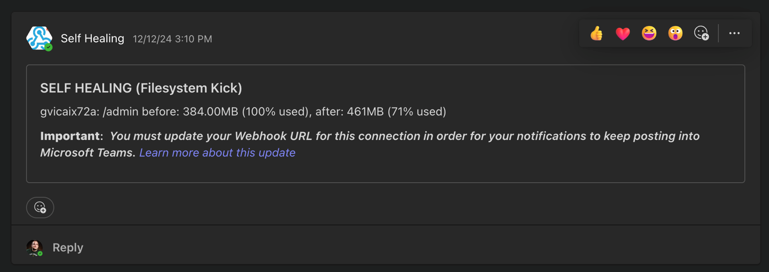
Kyle Tedeschi is a Principal Solutions Architect at AWS. He enjoys helping customers innovate, transform, and become leaders in their respective domains. Outside of work, Kyle is an avid snowboarder, car enthusiast, and traveler.

How SumUp built a low-latency feature store using Amazon EMR and Amazon Keyspaces

Post Syndicated from Shaheer Masoor original https://aws.amazon.com/blogs/big-data/how-sumup-built-a-low-latency-feature-store-using-amazon-emr-and-amazon-keyspaces/

This post was co-authored by Vadym Dolin, Data Architect at SumUp. In their own words, SumUp is a leading financial technology company, operating across 35 markets on three continents. SumUp helps small businesses be successful by enabling them to accept card payments in-store, in-app, and online, in a simple, secure, and cost-effective way. Today, SumUp card readers and other financial products are used by more than 4 million merchants around the world.

The SumUp Engineering team is committed to developing convenient, impactful, and secure financial products for merchants. To fulfill this vision, SumUp is increasingly investing in artificial intelligence and machine learning (ML). The internal ML platform in SumUp enables teams to seamlessly build, deploy, and operate ML solutions at scale.

One of the central elements of SumUp’s ML platform is the online feature store. It allows multiple ML models to retrieve feature vectors with single-digit millisecond latency, and enables application of AI for latency-critical use cases. The platform processes hundreds of transactions every second, with volume spikes during peak hours, and has steady growth that doubles the number of transactions every year. Because of this, the ML platform requires its low-latency feature store to be also highly reliable and scalable.

In this post, we show how SumUp built a millisecond-latency feature store. We also discuss the architectural considerations when setting up this solution so it can scale to serve multiple use cases, and present results showcasing the setups performance.

Overview of solution

To train ML models, we need historical data. During this phase, data scientists experiment with different features to test which ones produce the best model. From a platform perspective, we need to support bulk read and write operations. Read latency isn’t critical at this stage because the data is read into training jobs. After the models are trained and moved to production for real-time inference, we have the following requirements for the platform change: we need to support low-latency reads and use only the latest features data.

To fulfill these needs, SumUp built a feature store consisting of offline and online data stores. These were optimized for the requirements as described in the following table.

Data Store History Requirements ML Workflow Requirements Latency Requirements Storage Requirements Throughput Requirements Storage Medium
Offline Entire History Training Not important Cost-effective for large volumes Bulk read and writes Amazon S3
Online Only the latest Features Inference Single-digit millisecond Not important Read optimized Amazon Keyspaces

Amazon Keyspaces (for Apache Cassandra) is a serverless, scalable, and managed Apache Cassandra–compatible database service. It is built for consistent, single-digit-millisecond response times at scale. SumUp uses Amazon Keyspaces as a key-value pair store, and these features make it suitable for their online feature store. Delta Lake is an open-source storage layer that supports ACID transactions and is fully compatible with Apache Spark, making it highly performant at bulk read and write operations. You can store Delta Lake tables on Amazon Simple Storage Service (Amazon S3), which makes it a good fit for the offline feature store. Data scientists can use this stack to train models against the offline feature store (Delta Lake). When the trained models are moved to production, we switch to using the online feature store (Amazon Keyspaces), which offers the latest features set, scalable reads, and much lower latency.

Another important consideration is that we write a single feature job to populate both feature stores. Otherwise, SumUp would have to maintain two sets of code or pipelines for each feature creation job. We use Amazon EMR and create the features using PySpark DataFrames. The same DataFrame is written to both Delta Lake and Amazon Keyspaces, which eliminates the hurdle of having separate pipelines.

Finally, SumUp wanted to utilize managed services. It was important to SumUp that data scientists and data engineers focus their efforts on building and deploying ML models. SumUp had experimented with managing their own Cassandra cluster, and found it difficult to scale because it required specialized expertise. Amazon Keyspaces offered scalability without management and maintenance overhead. For running Spark workloads, we decided to use Amazon EMR. Amazon EMR makes it easy to provision new clusters and automatically or manually add and remove capacity as needed. You can also define a custom policy for auto scaling the cluster to suit your needs. Amazon EMR version 6.0.0 and above supports Spark version 3.0.0, which is compatible with Delta Lake.

It took SumUp 3 months from testing out AWS services to building a production-grade feature store capable of serving ML models. In this post we share a simplified version of the stack, consisting of the following components:

  • S3 bucket A – Stores the raw data
  • EMR cluster – For running PySpark jobs for populating the feature store
  • Amazon Keyspaces feature_store – Stores the online features table
  • S3 Bucket B – Stores the Delta Lake table for offline features
  • IAM role feature_creator – For running the feature job with the appropriate permissions
  • Notebook instance – For running the feature engineering code

We use a simplified version of the setup to make it easy to follow the code examples. SumUp data scientists use Jupyter notebooks for exploratory analysis of the data. Feature engineering jobs are deployed using an AWS Step Functions state machine, which consists of an AWS Lambda function that submits a PySpark job to the EMR cluster.

The following diagram illustrates our simplified architecture.

Prerequisites

To follow the solution, you need certain access rights and AWS Identity and Access Management (IAM) privileges:

  • An IAM user with AWS Command Line Interface (AWS CLI) access to an AWS account
  • IAM privileges to do the following:
    • Generate Amazon Keyspaces credentials
    • Create a keyspace and table
    • Create an S3 bucket
    • Create an EMR cluster
    • IAM Get Role

Set up the dataset

We start by cloning the project git repository, which contains the dataset we need to place in bucket A. We use a synthetic dataset, under Data/daily_dataset.csv. This dataset consists of energy meter readings for households. The file contains information like the number of measures, minimum, maximum, mean, median, sum, and std for each household on a daily basis. To create an S3 bucket (if you don’t already have one) and upload the data file, follow these steps:

  1. Clone the project repository locally by running the shell command:
    git clone https://github.com/aws-samples/amazon-keyspaces-emr-featurestore-kit.git

  2. On the Amazon S3 console, choose Create bucket.
  3. Give the bucket a name. For this post, we use featurestore-blogpost-bucket-xxxxxxxxxx (it’s helpful to append the account number to the bucket name to ensure the name is unique for common prefixes).
  4. Choose the Region you’re working in.
    It’s important that you create all resources in the same Region for this post.
  5. Public access is blocked by default, and we recommend that you keep it that way.
  6. Disable bucket versioning and encryption (we don’t need it for this post).
  7. Choose Create bucket.
  8. After the bucket is created, choose the bucket name and drag the folders Dataset and EMR into the bucket.

Set up Amazon Keyspaces

We need to generate credentials for Amazon Keyspaces, which we use to connect with the service. The steps for generating the credentials are as follows:

  1. On the IAM console, choose Users in the navigation pane.
  2. Choose an IAM user you want to generate credentials for.
  3. On the Security credentials tab, under Credentials for Amazon Keyspaces (for Apache Cassandra), choose Generate Credentials.
    A pop-up appears with the credentials, and an option to download the credentials. We recommend downloading a copy because you won’t be able to view the credentials again.We also need to create a table in Amazon Keyspaces to store our feature data. We have shared the schema for the keyspace and table in the GitHub project files Keyspaces/keyspace.cql and Keyspaces/Table_Schema.cql.
  4. On the Amazon Keyspaces console, choose CQL editor in the navigation pane.
  5. Enter the contents of the file Keyspaces/Keyspace.cql in the editor and choose Run command.
  6. Clear the contents of the editor, enter the contents of Keyspaces/Table_Schema.cql, and choose Run command.

Table creation is an asynchronous process, and you’re notified if the table is successfully created. You can also view it by choosing Tables in the navigation pane.

Set up an EMR cluster

Next, we set up an EMR cluster so we can run PySpark code to generate features. First, we need to set up a trust store password. A truststore file contains the Application Server’s trusted certificates, including public keys for other entities, this file is generated by the provided script and we need to provide a password for protecting this file. Amazon Keyspaces provides encryption in transit and at rest to protect and secure data transmission and storage, and uses Transport Layer Security (TLS) to help secure connections with clients. To connect to Amazon Keyspaces using TLS, we need to download an Amazon digital certificate and configure the Python driver to use TLS. This certificate is stored in a trust store; when we retrieve it, we need to provide the correct password.

  1. In the file EMR/emr_bootstrap_script.sh, update the following line to a password you want to use:
    # Create a JKS keystore from the certificate
    PASS={your_truststore_password_here}

  2. To point the bootstrap script to the one we uploaded to Amazon S3, update the following line to reflect the S3 bucket we created earlier:
    # Copy the Cassandra Connector config
    aws s3 cp s3://{your-s3-bucket}/EMR/app.config /home/hadoop/app.config

  3. To update the app.config file to reflect the correct trust store password, in the file EMR/app.config, update the value for truststore-password to the value you set earlier:
    {
        ssl-engine-factory {
          class = DefaultSslEngineFactory
          truststore-path = "/home/hadoop/.certs/cassandra_keystore.jks"
          truststore-password = "{your_password_here}"
        }
    }

  4. In the file EMR/app.config, update the following lines to reflect the Region and the user name and password generated earlier:
    contact-points = ["cassandra.<your-region>.amazonaws.com:9142"]
    load-balancing-policy.local-datacenter = <your-region>
    ..
    auth-provider {
        class = PlainTextAuthProvider
        username = "{your-keyspace-username}"
        password = "{your-keyspace-password}"
    }

    We need to create default instance roles, which are needed to run the EMR cluster.

  5. Update the contents S3 bucket created in the pre-requisite section by dragging the EMR folder into the bucket again.
  6. To create the default roles, run the create-default-roles command:
    aws emr create-default-roles

    Next, we create an EMR cluster. The following code snippet is an AWS CLI command that has Hadoop, Spark 3.0, Livy and JupyterHub installed. This also runs the bootstrapping script on the cluster to set up the connection to Amazon Keyspaces.

  7. Create the cluster with the following code. Provide the subnet ID to start a Jupyter notebook instance associated with this cluster, the S3 bucket you created earlier, and the Region you’re working in. You can provide the default Subnet, and to find this navigate to VPC>Subnets and copy the default subnet id.
    aws emr create-cluster --termination-protected --applications Name=Hadoop Name=Spark Name=Livy Name=Hive Name=JupyterHub --tags 'creator=feature-store-blogpost' --ec2-attributes '{"InstanceProfile":"EMR_EC2_DefaultRole","SubnetId":"your-subnet-id"}' --service-role EMR_DefaultRole --release-label emr-6.1.0 --log-uri 's3n://{your-s3-bucket}/elasticmapreduce/' --name 'emr_feature_store' --instance-groups '[{"InstanceCount":1,"EbsConfiguration":{"EbsBlockDeviceConfigs":[{"VolumeSpecification":{"SizeInGB":32,"VolumeType":"gp2"},"VolumesPerInstance":2}]},"InstanceGroupType":"CORE","InstanceType":"m5.xlarge","Name":"Core - 2"},{"InstanceCount":1,"EbsConfiguration":{"EbsBlockDeviceConfigs":[{"VolumeSpecification":{"SizeInGB":32,"VolumeType":"gp2"},"VolumesPerInstance":2}]},"InstanceGroupType":"MASTER","InstanceType":"m5.xlarge","Name":"Master - 1"}]' --bootstrap-actions '[{"Path":"s3://{your-s3-bucket HERE}/EMR/emr_bootstrap_script.sh","Name":"Execute_bootstarp_script"}]' --scale-down-behavior TERMINATE_AT_TASK_COMPLETION --region your-region

    Lastly, we create an EMR notebook instance to run the PySpark notebook Feature Creation and loading-notebook.ipynb (included in the repo).

  8. On the Amazon EMR console, choose Notebooks in the navigation pane.
  9. Choose Create notebook.
  10. Give the notebook a name and choose the cluster emr_feature_store.
  11. Optionally, configure the additional settings.
  12. Choose Create notebook.It can take a few minutes before the notebook instance is up and running.
  13. When the notebook is ready, select the notebook and choose either Open JupyterLab or Open Jupyter.
  14. In the notebook instance import, open the notebook Feature Creation and loading-notebook.ipynb (included in the repo) and change the kernel to PySpark.
  15. Follow the instructions in the notebook and run the cells one by one to read the data from Amazon S3, create features, and write these to Delta Lake and Amazon Keyspaces.

Performance testing

To test throughput for our online feature store, we run a simulation on the features we created. We simulate approximately 40,000 requests per second. Each request queries data for a specific key (an ID in our feature table). The process tasks do the following:

  • Initialize a connection to Amazon Keyspaces
  • Generate a random ID to query the data
  • Generate a CQL statement:
    SELECT * FROM feature_store.energy_data_features WHERE id=[list_of_ids[random_index between 0-5559]];

  • Start a timer
  • Send the request to Amazon Keyspaces
  • Stop the timer when the response from Amazon Keyspaces is received

To run the simulation, we start 245 parallel AWS Fargate tasks running on Amazon Elastic Container Service (Amazon ECS). Each task runs a Python script that makes 1 million requests to Amazon Keyspaces. Because our dataset only contains 5,560 unique IDs, we generate 1 million random numbers between 0–5560 at the start of the simulation and query the ID for each request. To run the simulation, we included the code in the folder Simulation. You can run the simulation in a SageMaker notebook instance by completing the following steps:

  1. On the Amazon SageMaker console, create a SageMaker notebook instance (or use an existing one).You can choose an ml.t3.large instance.
  2. Let SageMaker create an execution role for you if you don’t have one.
  3. Open the SageMaker notebook and choose Upload.
  4. Upload the Simulation folder from the repository. Alternatively, open a terminal window on the notebook instance and clone the repository https://github.com/aws-samples/amazon-keyspaces-emr-featurestore-kit.git.
  5. Follow the instructions and run the steps and cells in the Simulation/ECS_Simulation.ipynb notebook.
  6. On the Amazon ECS console, choose the cluster you provisioned with the notebook and choose the Tasks tab to monitor the tasks.

Each task writes the latency figures to a file and moves this to an S3 location. When the simulation ends, we collect all the data to get aggregated stats and plot charts.

In our setup, we set the capacity mode for Amazon Keyspaces to Provisioned RCU (read capacity units) at 40000 (fixed). After we start the simulation, the RCU rise close to 40000. After we start the simulation, the RCU (read capacity units) rise close to 40000, and the simulation takes around an hour to finish, as illustrated in the following visualization.

The first analysis we present is the latency distribution for the 245 million requests made during the simulation. Here the 99% percentile falls inside single-digit millisecond latency, as we would expect.

Quantile Latency (ms)
50% 3.11
90% 3.61
99% 5.56
99.90% 25.63

For the second analysis, we present the following time series charts for latency. The chart at the bottom shows the raw latency figures from all the 245 workers. The chart above that plots the average and minimum latency across all workers grouped over 1-second intervals. Here we can see both the minimum and the average latency throughout the simulation stays below 10 milliseconds. The third chart from the bottom plots maximum latency across all workers grouped over 1-second intervals. This chart shows occasional spikes in latency but nothing consistent we need to worry about. The top two charts are latency distributions; the one on the left plots all the data, and the one on the right plots the 99.9% percentile. Due to the presence of some outliers, the chart on the left shows a peak close to zero and a very tailed distribution. After we remove these outliers, we can see in the chart on the right that 99.9% of requests are completed in less than 5.5 milliseconds. This is a great result, considering we sent 245 million requests.

Cleanup

Some of the resources we created in this blogpost would incur costs if left running. Remember to terminate the EMR cluster, empty the S3 bucket and delete it, delete the Amazon KeySpaces table. Also delete the SageMaker and Amazon EMR notebooks. The Amazon ECS cluster is billed on tasks and would not incur any additional costs.

Conclusion

Amazon EMR, Amazon S3, and Amazon Keyspaces provide a flexible and scalable development experience for feature engineering. EMR clusters are easy to manage, and teams can share environments without compromising compute and storage capabilities. EMR bootstrapping makes it easy to install and test out new tools and quickly spin up environments to test out new ideas. Having the feature store split into offline and online store simplifies model training and deployment, and provides performance benefits.

In our testing, Amazon Keyspaces was able to handle peak throughput read requests within our desired requirement of single digit latency. It’s also worth mentioning that we found the on-demand mode to adapt to the usage pattern and an improvement in read/write latency a couple of days from when it was switched on.

Another important consideration to make for latency-sensitive queries is row length. In our testing, tables with lower row length had lower read latency. Therefore, it’s more efficient to split the data into multiple tables and make asynchronous calls to retrieve it from multiple tables.

We encourage you to explore adding security features and adopting security best practices according to your needs and potential company standards.

If you found this post useful, check out Loading data into Amazon Keyspaces with cqlsh for tips on how to tune Amazon Keyspaces, and Orchestrate Apache Spark applications using AWS Step Functions and Apache Livy on how to build and deploy PySpark jobs.


About the authors

Shaheer Mansoor is a Data Scientist at AWS. His focus is on building machine learning platforms that can host AI solutions at scale. His interest areas are ML Ops, Feature Stores, Model Hosting and Model Monitoring.

Vadym Dolinin is a Machine Learning Architect in SumUp. He works with several teams on crafting the ML platform, which enables data scientists to build, deploy, and operate machine learning solutions in SumUp. Vadym has 13 years of experience in the domains of data engineering, analytics, BI, and ML.

Oliver Zollikofer is a Data Scientist at AWS. He enables global enterprise customers to build and deploy machine learning models, as well as architect related cloud solutions.

How William Hill migrated NoSQL workloads at scale to Amazon Keyspaces

Post Syndicated from Kunal Gautam original https://aws.amazon.com/blogs/big-data/how-william-hill-migrated-nosql-workloads-at-scale-to-amazon-keyspaces/

Social gaming and online sports betting are competitive environments. The game must be able to handle large volumes of unpredictable traffic while simultaneously promising zero downtime. In this domain, user retention is no longer just desirable, it’s critical. William Hill is a global online gambling company based in London, England, and it is the founding member of the UK Betting and Gaming Council. They share the mission to champion the betting and gaming industry and set world-class standards to make sure of an enjoyable, fair, and safe betting and gambling experience for all of their customers. In sports betting, William Hill is an industry-leading brand, awarded with prestigious industry titles like the IGA Awards Sports Betting Operator of the year in 2019, 2020, and 2022, and the SBC Awards Racing Sportsbook of the Year in 2019. William Hill has been acquired by Caesars Entertainment, Inc (NASDAQ: CZR) in April 2021, and it’s the largest casino-entertainment company in the US and one of the world’s most diversified casino-entertainment providers. At the heart of William Hill gaming platform is a NoSQL database that maintains 100% uptime, scales in real-time to handle millions of users or more, and provides users with a responsive and personalized experience across all of their devices.

In this post, we’ll discuss how William Hill moved their workload from Apache Cassandra to Amazon Keyspaces (for Apache Cassandra) with zero downtime using AWS Glue ETL.

William Hill was facing challenges regarding scalability, cluster instability, high operational costs, and manual patching and server maintenance. They were looking for a NoSQL solution which was scalable, highly-available, and completely managed. This let them focus on providing better user experience rather than maintaining infrastructure. William Hill Limited decided to move forward with Amazon Keyspaces, since it can run Apache Cassandra workloads on AWS using the same Cassandra application code and developer tools used today, without the need to provision, patch, manage servers, install, maintain, or operate software.

Solution overview

William Hill Limited wanted to migrate their existing Apache Cassandra workloads to Amazon Keyspaces with a replication lag of minutes, with minimum migration costs and development efforts. Therefore, AWS Glue ETL was leveraged to deliver the desired outcome.

AWS Glue is a serverless data integration service that provides multiple benefits for migration:

  • No infrastructure to maintain; allocates the necessary computing power and runs multiple migration jobs simultaneously.
  • All-in-one pricing model that includes infrastructure and is 55% cheaper than other cloud data integration options.
  • No lock in with the service; possible to develop data migration pipelines in open-source Apache Spark (Spark SQL, PySpark, and Scala).
  • Migration pipeline can be scaled fearlessly with Amazon Keyspaces and AWS Glue.
  • Built-in pipeline monitoring to make sure of in-migration continuity.
  • AWS Glue ETL jobs make it possible to perform bulk data extraction from Apache Cassandra and ingest to Amazon Keyspaces.

In this post, we’ll take you through William Hill’s journey of building the migration pipeline from scratch to migrate the Apache Cassandra workload to Amazon Keyspaces by leveraging AWS Glue ETL with DataStax Spark Cassandra connector.

For the purpose of this post, let’s look at a typical Cassandra Network setup on AWS and the mechanism used to establish the connection with AWS Glue ETL. The migration solution described also works for Apache Cassandra hosted on on-premises clusters.

Architecture overview

The architecture demonstrates the migration environment that requires Amazon Keyspaces, AWS Glue, Amazon Simple Storage Service (Amazon S3), and the Apache Cassandra cluster. To avoid a high CPU utilization/saturation on the Apache Cassandra cluster during the migration process, you might want to deploy another Cassandra datacenter to isolate your production from the migration workload to make the migration process seamless for your customers.

Amazon S3 has been used for staging while migrating data from Apache Cassandra to Amazon Keyspaces to make sure that the IO load on Cassandra serving live traffic on production is minimized, in case the data upload to Amazon Keyspaces fails and a retry must be done.

Prerequisites

The Apache Cassandra cluster is hosted on Amazon Elastic Compute Cloud (Amazon EC2) instances, spread across three availability zones, and hosted in private subnets. AWS Glue ETL is hosted on Amazon Virtual Private Cloud (Amazon VPC) and thus needs a AWS Glue Studio custom Connectors and Connections to be setup to communicate with the Apache Cassandra nodes hosted on the private subnets in the customer VPC. Thereby, this enables the connection to the Cassandra cluster hosted in the VPC. The DataStax Spark Cassandra Connector must be downloaded and saved onto an Amazon S3 bucket: s3://$MIGRATION_BUCKET/jars/spark-cassandra-connector-assembly_2.12-3.2.0.jar.

Let’s create an AWS Glue Studio custom connector named cassandra_connection and its corresponding connection named conn-cassandra-custom for AWS region us-east-1.

For the connector created, create an AWS Glue Studio connection and populate it with network information VPC, and a Subnet allowing for AWS Glue ETL to establish a connection with Apache Casandra.

  • Name: conn-cassandra-custom
  • Network Options

Let’s begin by creating a keyspace and table in Amazon Keyspaces using Amazon Keyspaces Console or CQLSH, and then create a target keyspace named target_keyspace and a target table named target_table.

CREATE KEYSPACE target_keyspace WITH replication = {'class': 'SingleRegionStrategy'};

CREATE TABLE target_keyspace.target_table (
    userid      uuid,
    level       text,
    gameid      int,
    description text,
    nickname    text,
    zip         text,
    email       text,
    updatetime  text,
    PRIMARY KEY (userid, level, gameid)
) WITH default_time_to_live = 0 AND CUSTOM_PROPERTIES = {
	'capacity_mode':{
		'throughput_mode':'PROVISIONED',
		'write_capacity_units':76388,
		'read_capacity_units':3612
	}
} AND CLUSTERING ORDER BY (level ASC, gameid ASC);

After the table has been created, switch the table to on-demand mode to pre-warm the table and avoid AWS Glue ETL job throttling failures. The following script will update the throughput mode.

ALTER TABLE target_keyspace.target_table 
WITH CUSTOM_PROPERTIES = {
	'capacity_mode':{
		'throughput_mode':'PAY_PER_REQUEST'
	}
} 

Let’s go ahead and create two Amazon S3 buckets to support the migration process. The first bucket (s3://your-spark-cassandra-connector-bucket-name)should store the spark Cassandra connector assembly jar file, Cassandra, and Keyspaces configuration YAML files.

The second bucket (s3://your-migration-stage-bucket-name) will be used to store intermediate parquet files to identify the delta between the Cassandra cluster and the Amazon Keyspaces table to track changes between subsequent executions of the AWS Glue ETL jobs.

In the following KeyspacesConnector.conf, set your contact points to connect to Amazon Keyspaces, and replace the username and the password to the AWS credentials.

Using the RateLimitingRequestThrottler we can make sure that requests don’t exceed the configured Keyspaces capacity. The G1.X DPU creates one executor per worker. The RateLimitingRequestThrottler in this example is set for 1000 requests per second. With this configuration, and G.1X DPU, you’ll achieve 1000 request per AWS Glue worker. Adjust the max-requests-per-second accordingly to fit your workload. Increase the number of workers to scale throughput to a table.

datastax-java-driver {
  basic.request.consistency = "LOCAL_QUORUM"
  basic.contact-points = ["cassandra.us-east-1.amazonaws.com:9142"]
   advanced.reconnect-on-init = true
   basic.load-balancing-policy {
        local-datacenter = "us-east-1"
    }
    advanced.auth-provider = {
       class = PlainTextAuthProvider
       username = "user-at-sample"
       password = "S@MPLE=PASSWORD="
    }
    advanced.throttler = {
       class = RateLimitingRequestThrottler
       max-requests-per-second = 1000
       max-queue-size = 50000
       drain-interval = 1 millisecond
    }
    advanced.ssl-engine-factory {
      class = DefaultSslEngineFactory
      hostname-validation = false
    }
    advanced.connection.pool.local.size = 1
}

Similarly, create a CassandraConnector.conf file, set the contact points to connect to the Cassandra cluster, and replace the username and the password respectively.

datastax-java-driver {
  basic.request.consistency = "LOCAL_QUORUM"
  basic.contact-points = ["127.0.0.1:9042"]
   advanced.reconnect-on-init = true
   basic.load-balancing-policy {
        local-datacenter = "datacenter1"
    }
    advanced.auth-provider = {
       class = PlainTextAuthProvider
       username = "user-at-sample"
       password = "S@MPLE=PASSWORD="
    }
}

Build AWS Glue ETL migration pipeline with Amazon Keyspaces

To build reliable, consistent delta upload Glue ETL pipeline, let’s decouple the migration process into two AWS Glue ETLs.

  • CassandraToS3 Glue ETL: Read data from the Apache Cassandra cluster and transfer the migration workload to Amazon S3 in the Apache Parquet format. To identify incremental changes in the Cassandra tables, the job stores separate parquet files with primary keys with an updated timestamp.
  • S3toKeyspaces Glue ETL: Uploads the migration workload from Amazon S3 to Amazon Keyspaces. During the first run, the ETL uploads the complete data set from Amazon S3 to Amazon Keyspaces, and for the subsequent run calculates the incremental changes by comparing the updated timestamp across two subsequent runs and calculating the incremental difference. The job also takes care of inserting new records, updating existing records, and deleting records based on the incremental difference.

In this example, we’ll use Scala to write the AWS Glue ETL, but you can also use PySpark.

Let’s go ahead and create an AWS Glue ETL job named CassandraToS3 with the following job parameters:

aws glue create-job \
    --name "CassandraToS3" \
    --role "GlueKeyspacesMigration" \
    --description "Offload data from the Cassandra to S3" \
    --glue-version "3.0" \
    --number-of-workers 2 \
    --worker-type "G.1X" \
    --connections "conn-cassandra-custom" \
    --command "Name=glueetl,ScriptLocation=s3://$MIGRATION_BUCKET/scripts/CassandraToS3.scala" \
    --max-retries 0 \
    --default-arguments '{
        "--job-language":"scala",
        "--KEYSPACE_NAME":"source_keyspace",
        "--TABLE_NAME":"source_table",
        "--S3_URI_FULL_CHANGE":"s3://$MIGRATION_BUCKET/full-dataset/",
        "--S3_URI_CURRENT_CHANGE":"s3://$MIGRATION_BUCKET/incremental-dataset/current/",
        "--S3_URI_NEW_CHANGE":"s3://$MIGRATION_BUCKET/incremental-dataset/new/",
        "--extra-files":"s3://$MIGRATION_BUCKET/conf/CassandraConnector.conf",
        "--conf":"spark.cassandra.connection.config.profile.path=CassandraConnector.conf",
        "--class":"GlueApp"
    }'

The CassandraToS3 Glue ETL job reads data from the Apache Cassandra table source_keyspace.source_table and writes it to the S3 bucket in the Apache Parquet format. The job rotates the parquet files to help identify delta changes in the data between consecutive job executions. To identify inserts, updates, and deletes, you must know primary key and columns write times (updated timestamp) in the Cassandra cluster up front. Our primary key consists of several columns userid, level, gameid, and a write time column updatetime. If you have multiple updated columns, then you must use more than one write time columns with an aggregation function. For example, for email and updatetime, take the maximum value between write times for email and updatetime.

The following AWS Glue spark code offloads data to Amazon S3 using the spark-cassandra-connector. The script takes four parameters KEYSPACE_NAME, KEYSPACE_TABLE, S3_URI_CURRENT_CHANGE, S3_URI_CURRENT_CHANGE, and S3_URI_NEW_CHANGE.

To upload the data from Amazon S3 to Amazon Keyspaces, you must create a S3toKeyspaces Glue ETL job using the Glue spark code to read the parquet files from the Amazon S3 bucket created as an output of CassandraToS3 Glue job and identify inserts, updates, deletes, and execute requests against the target table in Amazon Keyspaces. The code sample provided takes four parameters: KEYSPACE_NAME, KEYSPACE_TABLE, S3_URI_CURRENT_CHANGE, S3_URI_CURRENT_CHANGE, and S3_URI_NEW_CHANGE.

Let’s go ahead and create our second AWS Glue ETL job S3toKeyspaces with the following job parameters:

aws glue create-job \
    --name "S3toKeyspaces" \
    --role "GlueKeyspacesMigration" \
    --description "Push data to Amazon Keyspaces" \
    --glue-version "3.0" \
    --number-of-workers 2 \
    --worker-type "G.1X" \
    --command "Name=glueetl,ScriptLocation=s3://amazon-keyspaces-backups/scripts/S3toKeyspaces.scala" \
    --default-arguments '{
        "--job-language":"scala",
        "--KEYSPACE_NAME":"target_keyspace",
        "--TABLE_NAME":"target_table",
        "--S3_URI_FULL_CHANGE":"s3://$MIGRATION_BUCKET/full-dataset/",
        "--S3_URI_CURRENT_CHANGE":"s3://$MIGRATION_BUCKET/incremental-dataset/current/",
        "--S3_URI_NEW_CHANGE":"s3://$MIGRATION_BUCKET/incremental-dataset/new/",
        "--extra-files":"s3://$MIGRATION_BUCKET/conf/KeyspacesConnector.conf",
        "--conf":"spark.cassandra.connection.config.profile.path=KeyspacesConnector.conf",
        "--class":"GlueApp"
    }'

Job scheduling

The final step is to configure AWS Glue Triggers or Amazon EventBridge depending on your scheduling needs to trigger S3toKeyspaces Glue ETL when the job CassandraToS3 has succeeded. If you want to run the CassandraToS3 based on the schedule and configure the schedule option, then the following example showcases how to schedule cassandraToS3 to run every 15 minutes.

Job tuning

There are Spark settings recommended to begin with Amazon Keyspaces, which can then be increased later as appropriate for your workload.

  • Use a Spark partition size (groups multiple Cassandra rows) smaller than 8 MBs to avoid replaying large Spark tasks during a task failure.
  • Use a low concurrent number of writes per DPU with a large number of retries. Add the following options to the job parameters: --conf spark.cassandra.query.retry.count=500 --conf spark.cassandra.output.concurrent.writes=3.
  • Set spark.task.maxFailures to a bounded value. For example, you can start from 32 and increase as needed. This option can help you increase a number of tasks reties during a table pre-warm stage. Add the following option to the job parameters: --conf spark.task.maxFailures=32
  • Another recommendation is to turn off batching to improve random access patterns. Add the following options to the job parameters:
    spark.cassandra.output.batch.size.rows=1
    spark.cassandra.output.batch.grouping.key=none spark.cassandra.output.batch.grouping.buffer.size=100
  • Randomize your workload. Amazon Keyspaces partitions data using partition keys. Although Amazon Keyspaces has built-in logic to help load balance requests for the same partition key, loading the data is faster and more efficient if you randomize the order because you can take advantage of the built-in load balancing of writing to different partitions. To spread the writes across the partitions evenly, you must randomize the data in the dataframe. You might use a rand function to shuffle rows in the dataframe.

Summary

William Hill was able to migrate their workload from Apache Cassandra to Amazon Keyspaces at scale using AWS Glue, without the needs to make any changes on their application tech stack. The adoption of Amazon Keyspaces has provided them with the headroom to focus on their Application and customer experience, as with Amazon Keyspaces there’s no need to manage servers, get performance at scale, highly-scalable, and secure solution with the ability to handle the sudden spike in demand.

In this post, you saw how to use AWS Glue to migrate the Cassandra workload to Amazon Keyspaces, and simultaneously keep your Cassandra source databases completely functional during the migration process. When your applications are ready, you can choose to cut over your applications to Amazon Keyspaces with minimal replication lag in sub minutes between the Cassandra cluster and Amazon Keyspaces. You can also use a similar pipeline to replicate the data back to the Cassandra cluster from Amazon Keyspaces to maintain data consistency, if needed. Here you can find the documents and code to help accelerate your migration to Amazon Keyspaces.


About the Authors

Nikolai Kolesnikov is a Senior Data Architect and helps AWS Professional Services customers build highly-scalable applications using Amazon Keyspaces. He also leads Amazon Keyspaces ProServe customer engagements.

Kunal Gautam is a Senior Big Data Architect at Amazon Web Services. Having experience in building his own Startup and working along with enterprises, he brings a unique perspective to get people, business and technology work in tandem for customers. He is passionate about helping customers in their digital transformation journey and enables them to build scalable data and advance analytics solutions to gain timely insights and make critical business decisions. In his spare time, Kunal enjoys Marathons, Tech Meetups and Meditation retreats.

How GE Proficy Manufacturing Data Cloud replatformed to improve TCO, data SLA, and performance

Post Syndicated from Jyothin Madari original https://aws.amazon.com/blogs/big-data/how-ge-proficy-manufacturing-data-cloud-replatformed-to-improve-tco-data-sla-and-performance/

This is post is co-authored by Jyothin Madari, Madhusudhan Muppagowni and Ayush Srivastava from GE.

GE Proficy Manufacturing Data Cloud (MDC), part of the GE Digital’s Manufacturing Execution Systems (MES) suite of solutions, allows GED’s customers to increase the derived value easily and quickly from the MES by reliably bringing enterprise-wide manufacturing data into the cloud and transforming it into a structured dataset for advanced analytics and deeper insights into the manufacturing processes.

In this post, we share how MDC modernized the hybrid cloud strategy by replatforming. This solution improved scalability, their data availability Service Level Agreement (SLA), and performance.

Challenge

MDC v1 was built on Predix services using industrial use case-optimized Predix services such as Predix Columnar Store (Cassandra) and Predix Insights (Amazon EMR). MDC evolved in both features and the underlying platform over the past year with a goal to improve TCO, data SLA, and performance. MDC’s customer base grew and the number of sites from customers grew to over 100 in the past couple of years. The increased number of sites needed more compute and storage capacity. This increased infrastructure and operational cost significantly, while introducing increased data latency and lowering the data freshness interval from the cloud.

How we started

MDC evaluated several vendors for their storage and compute capabilities using various measurements: security, performance, scalability, ease of management and operation, reduction of overall cost and increase in ROI, partnership, and migration help (technology assistance). The MDC team saw opportunities to improve the product by using native AWS services such as Amazon Redshift, AWS Glue, and Amazon Managed Workflows for Apache Airflow (Amazon MWAA), which made the product more performant and scalable while reducing operation costs and making it future-ready for advanced analytics and new customer use cases.

The GE Digital team, comprised of domain experts, developers, and QA, worked shoulder to shoulder with the AWS ProServe team, comprised of Solution Architects, Data Architects, and Big Data Experts, in determining the key architectural changes required and solutions to implementation challenges.

Overview of solution

The following diagram illustrates the high-level architecture of the solution.

This is a broad overview, and the specifics of networking and security between components are out of scope for this post.

The solution includes the following main steps and components:

  1. CDC and log collector – Compressed CSV data is collected from over 100 Manufacturing Data Sources Proficy Plant Applications and sinked into an Amazon Simple Storage Service (Amazon S3) bucket.
  2. S3 raw bucket – Our data lands in Amazon S3 without any transformation, but appropriately partitioned (tenant, site, date, and so on) for the ease of future processing.
  3. AWS Lambda – When the file lands in the S3 raw bucket, it triggers an S3 event notification, which invokes AWS Lambda. Lambda extracts metadata (bucket name, key name, date, and so on) from the event and saves it in Amazon DynamoDB.
  4. AWS Glue – Our goal is now to take CSV files, with varying schemas, and convert them into Apache Parquet format. An AWS Glue extract, transform, and load (ETL) job reads a list of files to be processed from the DynamoDB table and fetches them from the S3 raw bucket. We have preconfigured unified AVRO schemas in the AWS Glue Schema Registry for schema conversion. Converted data lands in the S3 raw Parquet bucket.
  5. S3 raw Parquet bucket – Data in this bucket is still raw and unmodified; only the format was changed. This intermediary storage is required due to schema and column order mismatch in CSV files.
  6. Amazon Redshift – The majority of transformations and data enrichment happens in this step. Amazon Redshift Spectrum consumes data from the S3 raw Parquet bucket and external PostgreSQL dimension tables (through a federated query). Transformations are performed via stored procedures, where we encapsulate logic for data transformation, data validation, and business-specific logic. The Amazon Redshift cluster is configured with concurrency scaling, auto workload management (WLM) with caching, and the latest RA3 instance types.
  7. MDC API – These custom-built, web-based, REST API microservices talk on the backend with Amazon Redshift and expose data to external users, business intelligence (BI) tools, and partners.
  8. Amazon Redshift data export and archival – On a scheduled basis, Amazon Redshift exports (UNLOAD command) contextualized and business-defined aggregated data. Exports are landed in the S3 bucket as Apache Parquet files.
  9. S3 Parquet export bucket – This bucket stores the exported data (hundreds of TBs) used by external users who need to run extensive, heavy analytics and AI or machine learning (ML) with various tools (such as Amazon EMR, Amazon Athena, Apache Spark, and Dremio).
  10. End-users – External users consume data from the API. The main use case here is reporting and visual analytics.
  11. Amazon MWAA – The orchestrator of the solution, Amazon MWAA is used for scheduling Amazon Redshift stored procedures, AWS Glue ETL jobs, and Amazon Redshift exports at regular intervals with error handling and retries built in.

Bringing it all together

MDC replaced both Predix Columnar Store (Cassandra) and Predix Insights (Amazon EMR) with Amazon Redshift for both storage of the MDC data models and compute (ELT). Amazon MWAA is used to schedule the workloads that do the bulk of the ELT. Lambda, AWS Glue, and DynamoDB are used to normalize the schema differences between sites. It was important not to disrupt MDC customers while replatforming. To achieve this, MDC used a phased approach to migrate the data models to Amazon Redshift. They used federated queries to query existing PostgreSQL for dimensional data, which facilitated having some of the data models in Amazon Redshift, while the others were in Cassandra with no interruption to MDC customers. Redshift Spectrum facilitated querying the raw data in Amazon S3 directly both for ETL and data validation.

75% of the MDC team along with the AWS ProServe team and AWS Solution Architects collaborated with the GE Digital Security Team and Platform Team to implement the architecture with AWS native services. It took approximately 9 months to implement, secure, and performance tune the architecture and migrate data models in three phases. Each phase has gone through a GE Digital internal security review. Amazon Redshift Auto WLM, short query acceleration, and tuning the sort keys to optimize querying patterns improved the Proficy MDC API performance. Because the unload of the data from Amazon Redshift was fast, Proficy MDC is now able to export the data much more frequently to our end customers.

Conclusion

With replatforming, Proficy MDC was able to improve ETL performance by approximately 75%. Data latency and freshness improved by approximately 87%. The solution reduced TCO of the platform by approximately 50%. Proficy MDC was also able reduce the infrastructure and operational cost. Improved performance and reduced latency has allowed us to speed up the next steps in our journey to modernize the enterprise data architecture and hybrid cloud data platform.


About the Authors

Jyothin Madari leads the Manufacturing Data Cloud (MDC) engineering team; part of the manufacturing suite of products at GE Digital. He has 18 years of experience, 4 of which is with GE Digital. Most recently he has been working on data migration projects with an aim to reduce costs and improve performance. He is an AWS Certified Cloud Practitioner, a keen learner and loves solving interesting problems. Connect with him on LinkedIn.

Madhusudhan (Madhu) Muppagowni is a Technical Architect and Principal Software Developer based in Silicon Valley, Bay Area, California.  He is passionate about Software Development and Architecture. He thrives on producing Well-Architected and Secure SaaS Products, Data Pipelines that can make a real impact.  He loves outdoors and an avid hiker and backpacker. Connect with him on LinkedIn.

Ayush Srivastava is a Senior Staff Engineer and Technical Anchor based in Hyderabad, India. He is passionate about Software Development and Architecture. He has Demonstrated track record of successfully technical anchoring small to large Secure SaaS Products, Data Pipelines from start to finish. He loves exploring different places and he says “I’m in love with cities I have never been to and people I have never met.” Connect with him on LinkedIn.

Karen Grygoryan is Data Architect with AWS ProServe. Connect with him on LinkedIn.

Gnanasekaran Kailasam is a Data Architect at AWS. He has worked with building data warehouses and big data solutions for over 16 years. He loves to learn new technologies and solving, automating, and simplifying customer problems with easy-to-use cloud data solutions on AWS. Connect with him on LinkedIn.

Supercharging Dream11’s Data Highway with Amazon Redshift RA3 clusters

Post Syndicated from Dhanraj Gaikwad original https://aws.amazon.com/blogs/big-data/supercharging-dream11s-data-highway-with-amazon-redshift-ra3-clusters/

This is a guest post by Dhanraj Gaikwad, Principal Engineer on Dream11 Data Engineering team.

Dream11 is the world’s largest fantasy sports platform, with over 120 million users playing fantasy cricket, football, kabaddi, basketball, hockey, volleyball, handball, rugby, futsal, American football, and baseball. Dream11 is the flagship brand of Dream Sports, India’s leading Sports Technology company, and has partnerships with several national and international sports bodies and cricketers.

In this post, we look at how we supercharged our data highway, the backbone of our major analytics pipeline, by migrating our Amazon Redshift clusters to RA3 nodes. We also look at why we were excited about this migration, the challenges we faced during the migration and how we overcame them, as well as the benefits accrued from the migration.

Background

The Dream11 Data Engineering team runs the analytics pipelines (what we call our Data Highway) across Dream Sports. In near-real time, we analyze various aspects that directly impact the end-user experience, which can have a profound business impact for Dream11.

Initially, we were analyzing upwards of terabytes of data per day with Amazon Redshift clusters that ran mainly on dc2.8xlarge nodes. However, due to a rapid increase in our user participation over the last few years, we observed that our data volumes increased multi-fold. Because we were using dc2.8xlarge clusters, this meant adding more nodes of dc2.8xlarge instance types to the Amazon Redshift clusters. Not only was this increasing our costs, it also meant that we were adding additional compute power when what we really needed was more storage. Because we anticipated significant growth during the Indian Premier League (IPL) 2021, we actively explored various options using our AWS Enterprise Support team. Additionally, we were expecting more data volume over the next few years.

The solution

After discussions with AWS experts and the Amazon Redshift product team, we at Dream11 were recommended the most viable option of migrating our Amazon Redshift clusters from dc2.8xlarge to the newer RA3 nodes. The most obvious reason for this was the decoupled storage from compute. As a result, we could use lesser nodes and move our storage to Amazon Redshift managed storage. This allowed us to respond to data volume growth in the coming years as well as reduce our costs.

To start off, we conducted a few elementary tests using an Amazon Redshift RA3 test cluster. After we were convinced that this wouldn’t require many changes in our Amazon Redshift queries, we decided to carry out a complete head-to-head performance test between the two clusters.

Validating the solution

Because the user traffic on the Dream11 app tends to spike during big ticket tournaments like the IPL, we wanted to ensure that the RA3 clusters could handle the same traffic that we usually experience during our peak. The AWS Enterprise Support team suggested using the Simple Replay tool, an open-sourced tool released by AWS that you can use to record and replay the queries from one Amazon Redshift cluster to another. This tool allows you to capture queries on a source Amazon Redshift cluster, and then replay the same queries on a destination Amazon Redshift cluster (or clusters). We decided to use this tool to capture our performance test queries on the existing dc2.8xlarge clusters and replay them on a test Amazon Redshift cluster composed of RA3 nodes. During this time of our experimentation, the newer version of the automated AWS CloudFormation-based toolset (now on GitHub), was not available.

Challenges faced

The first challenge came up when using the Simple Replay tool because there was no easy way to compare the performance of like-to-like queries on the two types of clusters. Although Amazon Redshift provides various statistics using meta-tables about individual queries and their performance, the Simple Replay tool adds additional comments in each Amazon Redshift query on the target cluster to make it easier to know if these queries were run by the Simple Replay tool. In addition, the Simple Replay tool drops comments from the queries on the source cluster.

Comparing each query performance with the Amazon Redshift performance test suite would mean writing additional scripts for easy performance comparison. An alternative would have been to modify the Simple Replay tool code, because it’s open source on GitHub. However, with the IPL 2022 beginning in just a few days, we had to explore another option urgently.

After further discussions with the AWS Enterprise Support team, we decided to use two test clusters: one with the old dc2.8xlarge nodes, and another with the newer RA3 nodes. The idea was to use the Simple Replay tool to run the captured queries from our original cluster on both test clusters. This meant that the queries would be identical on both test clusters, making it easier to compare. Although this meant running an additional test cluster for a few days, we went ahead with this option. As a side note, the newer automated AWS CloudFormation-based toolset does exactly the same in an automated way.

After we were convinced that most of our Amazon Redshift queries performed satisfactorily, we noticed that certain queries were performing slower on the RA3-based cluster than the dc2.8xlarge cluster. We narrowed down the problem to SQL queries with full table scans. We rectified it by following proper data modelling practices in the ETL workflow. Then we were ready to migrate to the newer RA3 nodes.

The migration to RA3

The migration from the old cluster to the new cluster was smoother than we thought. We used the elastic resize approach, which meant we only had a few minutes of Amazon Redshift downtime. We completed the migration successfully with a sufficient buffer timeline for more tests. Additional tests indicated that the new cluster performed how we wanted it to.

The trial by fire

The new cluster performed satisfactorily during our peak performance loads in the IPL as well as the following ICC T20 Cricket World Cup. We’re excited that the new RA3 node-based Amazon Redshift cluster can support our data volume growth needs without needing to increase the number of instance nodes.

We migrated from dc2 to RA3 in April 2021. The data volume has grown by 50% since then. If we had continued with dc2 instances, the cluster cost would have increased by 50%. However, because of the migration to RA3 instances, even with an increase in data volume by 50% since April 2021, the cluster cost has increased by 0.7%, which is attributed to an increase in storage cost.

Conclusion

Migrating to the newer RA3-based Amazon Redshift cluster helped us decouple our computing needs from our storage needs, and now we’re prepared for our expected data volume growth for the next few years. Moreover, we don’t need to add compute nodes if we only need storage, which is expected to bring down our costs in the long run. We did need to fine-tune some of our queries on the newer cluster. With the Simple Replay tool, we could do a direct comparison between the older and the newer cluster. You can also use the newer automated AWS CloudFormation-based toolset if you want to follow a similar approach.

We highly recommend RA3 instances. They give you the flexibility to size your RA3 cluster based on the
amount of data stored without increasing your compute costs.


About the Authors

Dhanraj Gaikwad is a Principal Data Engineer at Dream11. Dhanraj has more than 15 years of experience in the field of data and analytics. In his current role, Dhanraj is responsible for building the data platform for Dream Sports and is specialized in data warehousing, including data modeling, building data pipelines, and query optimizations. He is passionate about solving large-scale data problems and taking unique approaches to deal with them.

Sanket Raut is a Principal Technical Account Manager at AWS based in Vasai ,India. Sanket has more than 16 years of industry experience, including roles in cloud architecture, systems engineering, and software design. He currently focuses on enabling large startups to streamline their cloud operations and optimize their cloud spend. His area of interest is in serverless technologies.

How Paytm modernized their data pipeline using Amazon EMR

Post Syndicated from Rajat Bhardwaj original https://aws.amazon.com/blogs/big-data/how-paytm-modernized-their-data-pipeline-using-amazon-emr/

This post was co-written by Rajat Bhardwaj, Senior Technical Account Manager at AWS and Kunal Upadhyay, General Manager at Paytm.

Paytm is India’s leading payment platform, pioneering the digital payment era in India with 130 million active users. Paytm operates multiple lines of business, including banking, digital payments, bill recharges, e-wallet, stocks, insurance, lending and mobile gaming. At Paytm, the Central Data Platform team is responsible for turning disparate data from multiple business units into insights and actions for their executive management and merchants, who are small, medium or large business entities accepting payments from the Paytm platforms.

The Data Platform team modernized their legacy data pipeline with AWS services. The data pipeline collects data from different sources and runs analytical jobs, generating approximately 250K reports per day, which are consumed by Paytm executives and merchants. The legacy data pipeline was set up on premises using a proprietary solution and didn’t utilize the open-source Hadoop stack components such as Spark or Hive. This legacy setup was resource-intensive, having high CPU and I/O requirements. Analytical jobs took approximately 8–10 hours to complete, which often led to Service Level Agreements (SLA) breaches. The legacy solution was also prone to outages due to higher than expected hardware resource consumption. Its hardware and software limitations impacted the ability of the system to scale during peak load. Data models used in the legacy setup processed the entire data every time, which led to an increased processing time.

In this post, we demonstrate how the Paytm Central Data Platform team migrated their data pipeline to AWS and modernized it using Amazon EMR, Amazon Simple Storage Service (Amazon S3) and underlying AWS Cloud infrastructure along with Apache Spark. We optimized the hardware usage and reduced the data analytical processing, resulting in shorter turnaround time to generate insightful reports, all while maintaining operational stability and scale irrespective of the size of daily ingested data.

Overview of solution

The key to modernizing a data pipeline is to adopt an optimal incremental approach, which helps reduce the end-to-end cycle to analyze the data and get meaningful insights from it. To achieve this state, it’s vital to ingest incremental data in the pipeline, process delta records and reduce the analytical processing time. We configured the data sources to inherit the unchanged records and tuned the Spark jobs to only analyze the newly inserted or updated records. We used temporal data columns to store the incremental datasets until they’re processed. Data intensive Spark jobs are configured in incremental on-demand deduplicating mode to process the data. This helps to eliminate redundant data tuples from the data lake and reduces the total data volume, which saves compute and storage capacity. We also optimized the scanning of raw tables to restrict the scans to only the changed record set which reduced scanning time by approximately 90%. Incremental data processing also helps to reduce the total processing time.

At the time of this writing, the existing data pipeline has been operationally stable for 2 years. Although this modernization was vital, there is a risk of an operational outage while the changes are being implemented. Data skewing needs to be handled in the new system by an appropriate scaling strategy. Zero downtime is expected from the stakeholders because the reports generated from this system are vital for Paytm’s CXO, executive management and merchants on a daily basis.

The following diagram illustrates the data pipeline architecture.

Benefits of the solution

The Paytm Central Data Office team, comprised of 10 engineers, worked with the AWS team to modernize the data pipeline. The team worked for approximately 4 months to complete this modernization and migration project.

Modernizing the data pipeline with Amazon EMR 6.3 helped efficiently scale the system at a lower cost. Amazon EMR managed scaling helped reduce the scale-in and scale-out time and increase the usage of Amazon Elastic Compute Cloud (Amazon EC2) Spot Instances for running the Spark jobs. Paytm is now able to utilize a Spot to On-Demand ratio of 80:20, resulting in higher cost savings. Amazon EMR managed scaling also helped automatically scale the EMR cluster based on YARN memory usage with the desired type of EC2 instances. This approach eliminates the need to configure multiple Amazon EMR scaling policies tied to specific types of EC2 instances as per the compute requirements for running the Spark jobs.

In the following sections, we walk through the key tasks to modernize the data pipeline.

Migrate over 400 TB of data from the legacy storage to Amazon S3

Paytm team built a proprietary data migration application with the open-source AWS SDK for Java for Amazon S3 using the Scala programming language. This application can connect with multiple cloud providers , on-premises data centers and migrate the data to a central data lake built on Amazon S3.

Modernize the transformation jobs for over 40 data flows

Data flows are defined in the system for ingesting raw data, preprocessing the data and aggregating the data that is used by the analytical jobs for report generation. Data flows are developed using Scala programming language on Apache Spark. We use an Azkaban batch workflow job scheduler for ordering and tracking the Spark job runs. Workflows are created on Amazon EMR to schedule these Spark jobs multiple times during a day. We also implemented Spark optimizations to improve the operational efficiency for these jobs. We use Spark broadcast joins to handle the data skewness, which can otherwise lead to data spillage, resulting in extra storage needs. We also tuned the Spark jobs to avoid a  large number of small files, which is a known problem with Spark if not handled effectively. This is mainly because Spark is a parallel processing system and data loading is done through multiple tasks where each task can load into multiple partition. Data-intensive jobs are run using Spark stages.

The following is the code snippet for the Scala jobs:

nodes:
  - name: jobC
    type: noop
    # jobC depends on jobA and jobB
    dependsOn:
      - jobA
      - jobB

  - name: jobA
    type: command
    config:
      command: echo "This is an echoed text."

  - name: jobB
    type: command
    config:
      command: pwd

Validate the data

Accuracy of the data reports is vital for the modern data pipeline. The modernized pipeline has additional data reconciliation steps to improve the correctness of data across the platform. This is achieved by having greater programmatic control over the processed data. We could only reconcile data for the legacy pipeline after the entire data processing was complete. However, the modern data pipeline enables all the transactions to be reconciled at every step of the transaction, which gives granular control for data validation. It also helps isolate the cause of any data processing errors. Automated tests were done before go-live to compare the data records generated by the legacy vs. the modern system to ensure data sanity. These steps helped ensure the overall sanity of the processed data by the new system. Deduplication of data is done frequently via on-demand queries to eliminate redundant data, thereby reducing the processing time. As an example, if there are transactions which are already consumed by the end clients but still a part of the data-set, these can be eliminated by the deduplication, resulting in processing of only the newer transactions for the end client consumption.

The following sample query uses Spark SQL for on-demand deduplication of raw data at the reporting layer:

Insert over table  <<table>>
select col1,col2,col3 ---...coln 
from (select t.*
            ,row_number() over(order by col) as rn 
      from <<table>>
     ) t
where rn = 1

What we achieved as part of the modernization

With the new data pipeline, we reduced the compute infrastructure by 400% which helps to save  compute cost. The earlier legacy stack was running on over 6,000 virtual cores. Optimization techniques helped to run the same system at an improved scale, with approximately 1,500 virtual cores. We are able to reduce the compute and storage capacity for 400 TB of data and 40 data flows after migrating to Amazon EMR. We also achieved Spark optimizations, which helped to reduce the runtime of the jobs by 95% (from 8–10 hours to 20–30 minutes), CPU consumption by 95%, I/O by 98% and overall computation time by 80%. The incremental data processing approach helped to scale the system despite data skewness, which wasn’t the case with the legacy solution.

Conclusion

In this post, we showed how Paytm modernized their data lake and data pipeline using Amazon EMR, Amazon S3, underlying AWS Cloud infrastructure and Apache Spark. Choice of these cloud & big-data technologies helped to address the challenges for operating a big data pipeline because the type and volume of data from disparate sources adds complexity to the analytical processing.

By partnering with AWS, the Paytm Central Data Platform team created a modern data pipeline in a short amount of time. It provides reduced data analytical times with astute scaling capabilities, generating high-quality reports for the executive management and merchants on a daily basis.

As next steps, do a deep dive bifurcating the data collection and data processing stages for your data pipeline system. Each stage of the data pipeline should be appropriately designed and scaled to reduce the processing time while maintaining integrity of the reports generated as an output.

If you have feedback about this post, submit comments in the Comments section below.


About the Authors

Rajat Bhardwaj is a Senior Technical Manager with Amazon Web Services based in India, having 23 years of work experience with multiple roles in software development, telecom, and cloud technologies. He works along with AWS Enterprise customers, providing advocacy and strategic technical guidance to help plan and build solutions using AWS services and best practices. Rajat is an avid runner, having competed several half and full marathons in recent years.

Kunal Upadhyay is a General Manager with Paytm Central Data Platform team based out of Bengaluru, India. Kunal has 16 years of experience in big data, distributed computing, and data intelligence. When not building software, Kunal enjoys travel and exploring the world, spending time with friends and family.

Use Amazon Kinesis Data Firehose to extract data insights with Coralogix

Post Syndicated from Tal Knopf original https://aws.amazon.com/blogs/big-data/use-amazon-kinesis-data-firehose-to-extract-data-insights-with-coralogix/

This is a guest blog post co-written by Tal Knopf at Coralogix.

Digital data is expanding exponentially, and the existing limitations to store and analyze it are constantly being challenged and overcome. According to Moore’s Law, digital storage becomes larger, cheaper, and faster with each successive year. The advent of cloud databases is just one example of how this is happening. Previous hard limits on storage size have become obsolete since their introduction.

In recent years, the amount of available data storage in the world has increased rapidly, reflecting this new reality. If you took all the information just from US academic research libraries and lumped it together, it would add up to 2 petabytes.

Coralogix has worked with AWS to bring you a solution to allow for the flawless integration of high volumes of data with the Coralogix platform for analysis, using Amazon Kinesis Data Firehose.

Kinesis Data Firehose and Coralogix

Kinesis Data Firehose delivers real-time streaming data to destinations like Amazon Simple Storage Service (Amazon S3), Amazon Redshift, or Amazon OpenSearch Service (successor to Amazon Elasticsearch Service), and now supports delivering streaming data to Coralogix. There is no limit on the number of delivery streams, so you can use it to get data from multiple AWS services.

Kinesis Data Firehose provides built-in, fully managed error handling, transformation, conversion, aggregation, and compression functionality, so you don’t need to write applications to handle these complexities.

Coralogix is an AWS Partner Network (APN) Advanced Technology Partner with AWS DevOps Competency. The platform enables you to easily explore and analyze logs to gain deeper insights into the state of your applications and AWS infrastructure. You can analyze all your AWS service logs while storing only the ones you need, and generate metrics from aggregated logs to uncover and alert on trends in your AWS services.

Solution overview

Imagine a pipe flowing with data—messages, to be more specific. These messages can contain log lines, metrics, or any other type of data you want to collect.

Clearly, there must be something pushing data into the pipe; this is the provider. There must also be a mechanism for pulling data out of the pipe; this is the consumer.

Kinesis Data Firehose makes it easy to collect, process, and analyze real-time, streaming data by grouping the pipes together in the most efficient way to help with management and scaling.

It offers a few significant benefits compared to other solutions:

  • Keeps monitoring simple – With this solution, you can configure AWS Web Application Firewall (AWS WAF), Amazon Route 53 Resolver Query Logs, or Amazon API Gateway to deliver log events directly to Kinesis Data Firehose.
  • Integrates flawlessly – Most AWS services use Amazon CloudWatch by default to collect logs, metrics, and additional events data. CloudWatch logs can easily be sent using the Firehose delivery stream.
  • Flexible with minimum maintenance – To configure Kinesis Data Firehose with the Coralogix API as a destination, you only need to set up the authentication in one place, regardless of the amount of services or integrations providing the actual data. You can also configure an S3 bucket as a backup plan. You can back up all log events or only those exceeding a specified retry duration.
  • Scale, scale, scale – Kinesis Data Firehose scales up to meet your needs with no need for you to maintain it. The Coralogix platform is also built for scale and can meet all your monitoring needs as your system grows.

Prerequisites

To get started, you must have the following:

  • A Coralogix account. If you don’t already have an account, you can sign up for one.
  • A Coralogix private key.

To find your key, in your Coralogix account, choose API Keys on the Data Flow menu.

Locate the key for Send Your Data.

Set up your delivery stream

To configure your deliver stream, complete the following steps:

  1. On the Kinesis Data Firehose console, choose Create delivery stream.
  2. Under Choose source and destination, for Source, choose Direct PUT.
  3. For Destination, choose Coralogix.
  4. For Delivery stream name¸ enter a name for your stream.
  5. Under Destination settings, for HTTP endpoint name, enter a name for your endpoint.
  6. For HTTP endpoint URL, enter your endpoint URL based on your Region and Coralogix account configuration.
  7. For Access key, enter your Coralogix private key.
  8. For Content encoding¸ select GZIP.
  9. For Retry duration, enter 60.

To override the logs applicationName, subsystemName, or computerName, complete the optional steps under Parameters.

  1. For Key, enter the log name.
  2. For Value, enter a new value to override the default.
  3. For this post, leave the configuration under Buffer hints as is.
  4. In the Backup settings section, for Source record in Amazon S3, select Failed data only (recommended).
  5. For S3 backup bucket, choose an existing bucket or create a new one.
  6. Leave the settings under Advanced settings as is.
  7. Review your settings and choose Create delivery stream.

Logs subscribed to your delivery stream are immediately sent and available for analysis within Coralogix.

Conclusion

Coralogix provides you with full visibility into your logs, metrics, tracing, and security data without relying on indexing to provide analysis and insights. When you use Kinesis Data Firehose to send data to Coralogix, you can easily centralize all your AWS service data for streamlined analysis and troubleshooting.

To get the most out of the platform, check out Getting Started with Coralogix, which provides information on everything from parsing and enrichment to alerting and data clustering.


About the Authors

Tal Knopf is the Head of Customer DevOps at Coralogix. He uses his vast experience in designing and building customer-focused solutions to help users extract the full value from their observability data. Previously, he was a DevOps engineer in Akamai and other companies, where he specialized in large-scale systems and CDN solutions.

Ilya Rabinov is a Solutions Architect at AWS. He works with ISVs at late stages of their journey to help build new products, migrate existing applications, or optimize workloads on AWS. His ares of interest include machine learning, artificial intelligence, security, DevOps culture, CI/CD, and containers.

How SailPoint solved scaling issues by migrating legacy big data applications to Amazon EMR on Amazon EKS

Post Syndicated from Richard Li original https://aws.amazon.com/blogs/big-data/how-sailpoint-solved-scaling-issues-by-migrating-legacy-big-data-applications-to-amazon-emr-on-amazon-eks/

This post is co-written with Richard Li from SailPoint.

SailPoint Technologies is an identity security company based in Austin, TX. Its software as a service (SaaS) solutions support identity governance operations in regulated industries such as healthcare, government, and higher education. SailPoint distinguishes multiple aspects of identity as individual identity security services, including cloud governance, SaaS management, access risk governance, file access management, password management, provisioning, recommendations, and separation of duties, as well as access certification, access insights, access modeling, and access requests.

In this post, we share how SailPoint updated its platform for big data operations, and solved scaling issues by migrating legacy big data applications to Amazon EMR on Amazon EKS.

The challenge with the legacy data environment

SailPoint acquired a SaaS software platform that processes and analyzes identity, resource, and usage data from multiple cloud providers, and provides access insights, usage analysis, and access risk analysis. The original design criteria of the platform was focused on serving small to medium-sized companies. To quickly process these analytics insights, many of these processing workloads were done inside many microservices through streaming connections.

After acquisition, we set a goal to expand the platform’s capability to handle customers with large cloud footprints over multiple cloud providers, sometime over hundreds or even thousands of accounts producing large amount of cloud event data.

The legacy architecture has a simplistic approach for data processing, as shown in the following diagram. We were processing the vast majority of event data in-service and directly ingested into Amazon Relational Database Service (Amazon RDS), which we then merged with a graph database to form the final view..

We needed to convert this into a scalable process that could handle customers of any size. To address this challenge, we had to quickly introduce a big data processing engine in the platform.

How migrating to Amazon EMR on EKS helped solve this challenge

When evaluating the platform for our big data operations, several factors made Amazon EMR on EKS a top choice.

The amount of event data we receive at any given time is generally unpredictable. To stay cost-effective and efficient, we need a platform that is capable of scaling up automatically when the workload increases to reduce wait time, and can scale down when the capacity is no longer needed to save cost. Because our existing application workloads are already running on an Amazon Elastic Kubernetes Service (Amazon EKS) cluster with the cluster autoscaler enabled, running Amazon EMR on EKS on top of our existing EKS cluster fits this need.

Amazon EMR on EKS can safely coexist on an EKS cluster that is already hosting other workloads, be contained within a specified namespace, and have controlled access through use of Kubernetes role-based access control and AWS Identity and Access Management (IAM) roles for service accounts. Therefore, we didn’t have to build new infrastructures just for Amazon EMR. We simply linked up Amazon EMR on EKS with our existing EKS cluster running our application workloads. This reduced the amount of DevOps support needed, and significantly sped up our implementation and deployment timeline.

Unlike Amazon EMR on Amazon Elastic Compute Cloud (Amazon EC2), because our EKS cluster spans over multiple Availability Zones, we can control Spark pods placements using Kubernetes’s pod scheduling and placement strategy to achieve higher fault tolerance.

With the ability to create and use custom images in Amazon EMR on EKS, we could also utilize our existing container-based application build and deployment pipeline for our Amazon EMR on EKS workload without any modifications. This also gave us additional benefit in reducing job startup time because we package all job scripts as well as all dependencies with the image, without having to fetch them at runtime.

We also utilize AWS Step Functions as our core workflow engine. The native integration of Amazon EMR on EKS with Step Functions is another bonus where we didn’t have to build custom code for job dispatch. Instead, we could utilize the Step Functions native integration to seamlessly integrate Amazon EMR jobs with our existing workflow, with very little effort.

In merely 5 months, we were able to go from design, to proof of concept, to rolling out phase 1 of the event analytics processing. This vastly improved our event analytics processing capability by extending horizontal scalability, which gave us the ability to take customers with significantly larger cloud footprints than the legacy platform was designed for.

During the development and rollout of the platform, we also found that the Spark History Server provided by Amazon EMR on EKS was very useful in terms of helping us identify performance issues and tune the performance of our jobs.

As of this writing, the phase 1 rollout, which includes the event processing component of the core analytics processing, is complete. We’re now expanding the platform to migrate additional components onto Amazon EMR on EKS. The following diagram depicts our future architecture with Amazon EMR on EKS when all phases are complete.

In addition, to improve performances and reduce costs, we’re currently testing the Spark dynamic resource allocation support of Amazon EMR on EKS. This would automatically scale up and down the job executors based on load, and therefore boost performance when needed and reduce cost when the workload is low. Furthermore, we’re investigating the possibility to reduce the overall cost and increase performance by utilizing the pod template feature that would allow us to seamlessly transition our Amazon EMR job workload to AWS Graviton based instances.

Conclusion

With Amazon EMR on EKS, we can now onboard new customers and process vast amounts of data in a cost-effective manner, which we couldn’t do with our legacy environment. We plan to expand our Amazon EMR on EKS footprint to handle all our transform and load data analytics processes.


About the Authors

Richard Li is a senior staff software engineer on the SailPoint Technologies Cloud Access Management team.

Janak Agarwal is a product manager for Amazon EMR on Amazon EKS at AWS.

Kiran Guduguntla is a WW Go-to-Market Specialist for Amazon EMR at AWS. He works with AWS customers across the globe to strategize, build, develop, and deploy modern data analytics solutions.