Post Syndicated from Pengfei Shao original https://aws.amazon.com/blogs/security/protect-apis-with-amazon-api-gateway-and-perimeter-protection-services/
As Amazon Web Services (AWS) customers build new applications, APIs have been key to driving the adoption of these offerings. APIs simplify client integration and provide for efficient operations and management of applications by offering standard contracts for data exchange. APIs are also the front door to hosted applications that need to be effectively secured, monitored, and metered to provide resilient infrastructure.
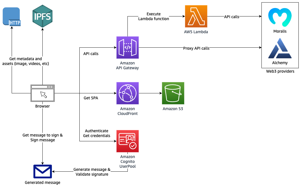
In this post, we will discuss how to help protect your APIs by building a perimeter protection layer with Amazon CloudFront, AWS WAF, and AWS Shield and putting it in front of Amazon API Gateway endpoints. Amazon API Gateway is a fully managed AWS service that you can use to create, publish, maintain, monitor, and secure REST, HTTP, and WebSocket APIs at any scale.
Solution overview
CloudFront, AWS WAF, and Shield provide a layered security perimeter that co-resides at the AWS edge and provides scalable, reliable, and high-performance protection for applications and content. For more information, see the AWS Best Practices for DDoS Resiliency whitepaper.
By using CloudFront as the front door to APIs that are hosted on API Gateway, globally distributed API clients can get accelerated API performance. API Gateway endpoints that are hosted in an AWS Region gain access to scaled distributed denial of service (DDoS) mitigation capacity across the AWS global edge network.
When you protect CloudFront distributions with AWS WAF, you can protect your API Gateway API endpoints against common web exploits and bots that can affect availability, compromise security, or consume excessive resources. AWS Managed Rules for AWS WAF help provide protection against common application vulnerabilities or other unwanted traffic, without the need for you to write your own rules. AWS WAF rate-based rules automatically block traffic from source IPs when they exceed the thresholds that you define, which helps to protect your application against web request floods, and alerts you to sudden spikes in traffic that might indicate a potential DDoS attack.
Shield mitigates infrastructure layer DDoS attacks against CloudFront distributions in real time, without observable latency. When you protect a CloudFront distribution with Shield Advanced, you gain additional detection and mitigation against large and sophisticated DDoS attacks, near real-time visibility into attacks, and integration with AWS WAF. When you configure Shield Advanced automatic application layer DDoS mitigation, Shield Advanced responds to application layer (layer 7) attacks by creating, evaluating, and deploying custom AWS WAF rules.
To take advantage of the perimeter protection layer built with CloudFront, AWS WAF, and Shield, and to help avoid exposing API Gateway endpoints directly, you can use the following approaches to restrict API access through CloudFront only. For more information about these approaches, see the Security Overview of Amazon API Gateway whitepaper.
- CloudFront can insert the X-API-Key header before it forwards the request to API Gateway, and API Gateway validates the API key when receiving the requests. For more information, see Protecting your API using Amazon API Gateway and AWS WAF — Part 2.
- CloudFront can insert a custom header (not X-API-Key) with a known secret that is shared with API Gateway. An AWS Lambda custom request authorizer that is configured in API Gateway validates the secret. For more information, see Restricting access on HTTP API Gateway Endpoint with Lambda Authorizer.
- CloudFront can sign the request with AWS Signature Version 4 by using Lambda@Edge before it sends the request to API Gateway. Configured AWS Identity and Access Management (IAM) authorization in API Gateway validates the signature and verifies the identity of the requester.
Although the X-API-Key header approach is straightforward to implement at a lower cost, it’s only applicable to customers who are using REST API endpoints. If the X-API-Key header already exists, CloudFront will overwrite it. The custom header approach addresses this limitation, but it has an additional cost due to the use of the Lambda authorizer. With both approaches, there is an operational overhead for managing keys and rotating the keys periodically. Also, it isn’t a security best practice to use long-term secrets for authorization.
By using the AWS Signature Version 4 approach, you can minimize this type of operational overhead through the use of requests signed with Signature Version 4 in Lambda@Edge. The signing uses temporary credentials that AWS Security Token Service (AWS STS) provides, and built-in API Gateway IAM authorization performs the request signature validation. There is an additional Lambda@Edge cost in this approach. This approach supports the three API endpoint types available in API Gateway — REST, HTTP, and WebSocket — and it helps secure requests by verifying the identity of the requester, protecting data in transit, and protecting against potential replay attacks. We describe this approach in detail in the next section.
Solution architecture
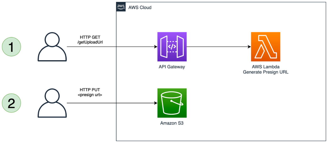
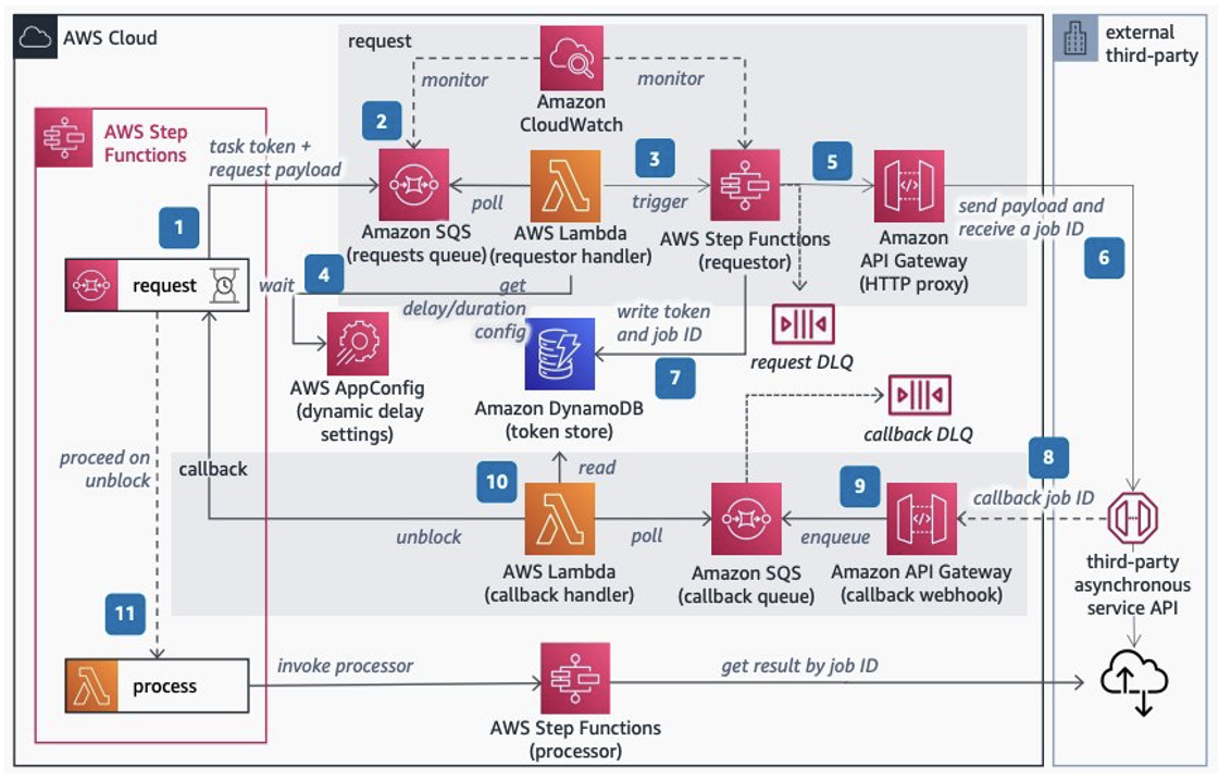
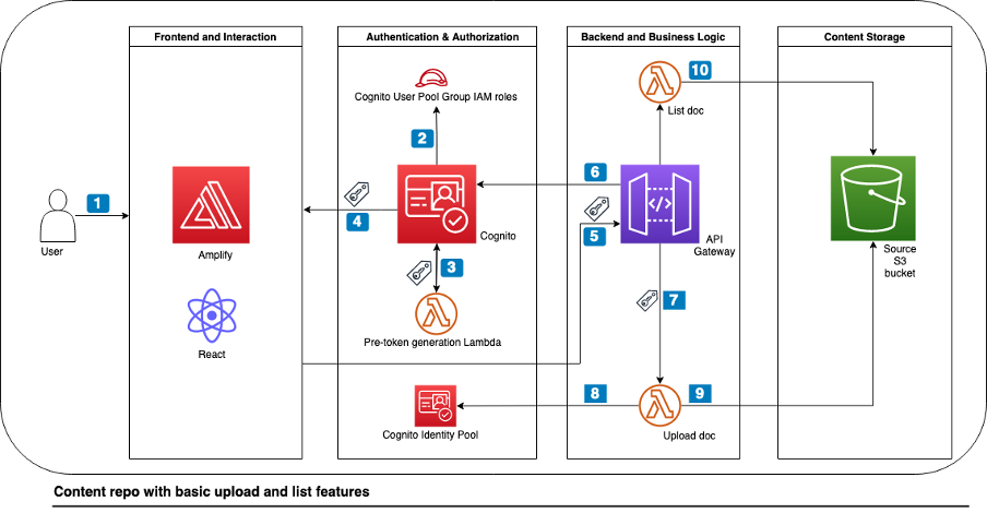
Figure 1 shows the architecture of the Signature Version 4 solution.
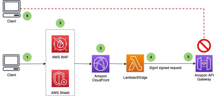
Figure 1: High-level flow of a client request with sequence of events
The sequence of events that occurs when the client sends a request is as follows:
- A client sends a request to an API endpoint that is fronted by CloudFront.
- AWS WAF inspects the request at the edge location according to the web access control list (web ACL) rules that you configured. With Shield Advanced automatic application-layer mitigation enabled, when Shield Advanced detects a DDoS attack and identifies the attack signatures, Shield Advanced creates AWS WAF rules inside an associated web ACL to mitigate the attack.
- CloudFront handles the request and invokes the Lambda@Edge function before sending the request to API Gateway.
- The Lambda@Edge function signs the request with Signature Version 4 by adding the necessary headers.
- API Gateway verifies the Lambda@Edge function with the necessary permissions and sends the request to the backend.
- An unauthorized client sends a request to an API Gateway endpoint, and it receives the HTTP 403 Forbidden message.
Solution deployment
The sample solution contains the following main steps:
- Preparation
- Deploy the CloudFormation template
- Enable IAM authorization in API Gateway
- Confirm successful viewer access to the CloudFront URL
- Confirm that direct access to the API Gateway API URL is blocked
- Review the CloudFront configuration
- Review the Lambda@Edge function and its IAM role
- Review the AWS WAF web ACL configuration
- (Optional) Protect the CloudFront distribution with Shield Advanced
Step 1: Preparation
Before you deploy the solution, you will first need to create an API Gateway endpoint.
To create an API Gateway endpoint
- Choose the following Launch Stack button to launch a CloudFormation stack in your account.

Note: The stack will launch in the US East (N. Virginia) Region (us-east-1). To deploy the solution to another Region, download the solution’s CloudFormation template, and deploy it to the selected Region.
When you launch the stack, it creates an API called PetStoreAPI that is deployed to the prod stage.
- In the Stages navigation pane, expand the prod stage, select GET on /pets/{petId}, and then copy the Invoke URL value of https://api-id.execute-api.region.amazonaws.com/prod/pets/{petId}. {petId} stands for a path variable.
- In the address bar of a browser, paste the Invoke URL value. Make sure to replace {petId} with your own information (for example, 1), and press Enter to submit the request. A 200 OK response should return with the following JSON payload:
{
  "id": 1,
  "type": "dog",
  "price": 249.99
}
In this post, we will refer to this API Gateway endpoint as the CloudFront origin.
Step 2: Deploy the CloudFormation template
The next step is to deploy the CloudFormation template of the solution.
The CloudFormation template includes the following:
- A CloudFront distribution that uses an API Gateway endpoint as the origin
- An AWS WAF web ACL that is associated with the CloudFront distribution
- A Lambda@Edge function that is used to sign the request with Signature Version 4 and that the CloudFront distribution invokes before the request is forwarded to the origin on the CloudFront distribution
- An IAM role for the Lambda@Edge function
To deploy the CloudFormation template
- Choose the following Launch Stack button to launch a CloudFormation stack in your account.
Note: The stack will launch in the US East N. Virginia Region (us-east-1). To deploy the solution to another Region, download the solution’s CloudFormation template, provide the required parameters, and deploy it to the selected Region.
- On the Specify stack details page, update with the following:
- For Stack name, enter APIProtection
- For the parameter APIGWEndpoint, enter the API Gateway endpoint in the following format. Make sure to replace <Region> with your own information.
{api-id}.execute-api.<Region>.amazonaws.com - Choose Next to continue the stack deployment.
It takes a couple of minutes to finish the deployment. After it finishes, the Output tab lists the CloudFront domain URL, as shown in Figure 2.

Figure 2: CloudFormation template output
Step 3: Enable IAM authorization in API Gateway
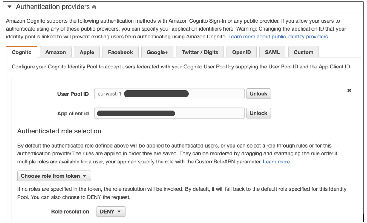
Before you verify the solution, you will enable IAM authorization on the API endpoint first, which enforces Signature Version 4 verification at API Gateway. The following steps are applied for a REST API; you could also enable IAM authorization on an HTTP API or WebSocket API.
To enable IAM authorization in API Gateway
- In the API Gateway console, choose the name of your API.
- In the Resources pane, choose the GET method for the resource /pets. In the Method Execution pane, choose Method Request.
- Under Settings, for Authorization, choose the pencil icon (Edit). Then, in the dropdown list, choose AWS_IAM, and choose the check mark icon (Update).
- Repeat steps 2 and 3 for the resource /pets/{petId}.
- Deploy your API so that the changes take effect. When deploying, choose prod as the stage.
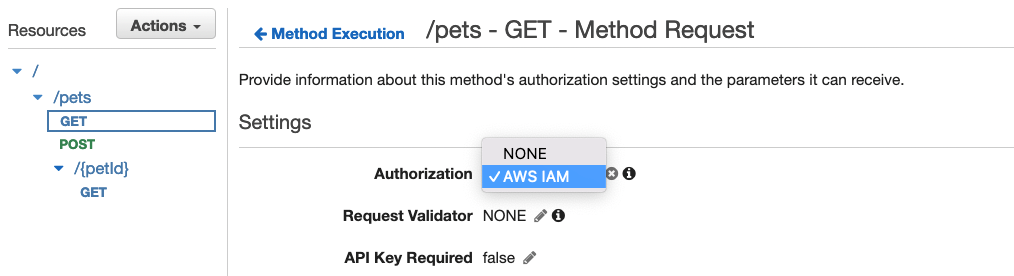
Figure 3: Enable IAM authorization in API Gateway
Step 4: Confirm successful viewer access to the CloudFront URL
Now that you’ve deployed the setup, you can verify that you are able to access the API through the CloudFront distribution.
To confirm viewer access through CloudFront
- In the CloudFormation console, choose the APIProtection stack.
- On the stack Outputs tab, copy the value for the CFDistribution entry and append /prod/pets to it, then open the URL in a new browser tab or window. The result should look similar to the following, which confirms successful viewer access through CloudFront.

Figure 4: Successful API response when accessing API through CloudFront distribution

Step 5: Confirm that direct access to the API Gateway API URL is blocked
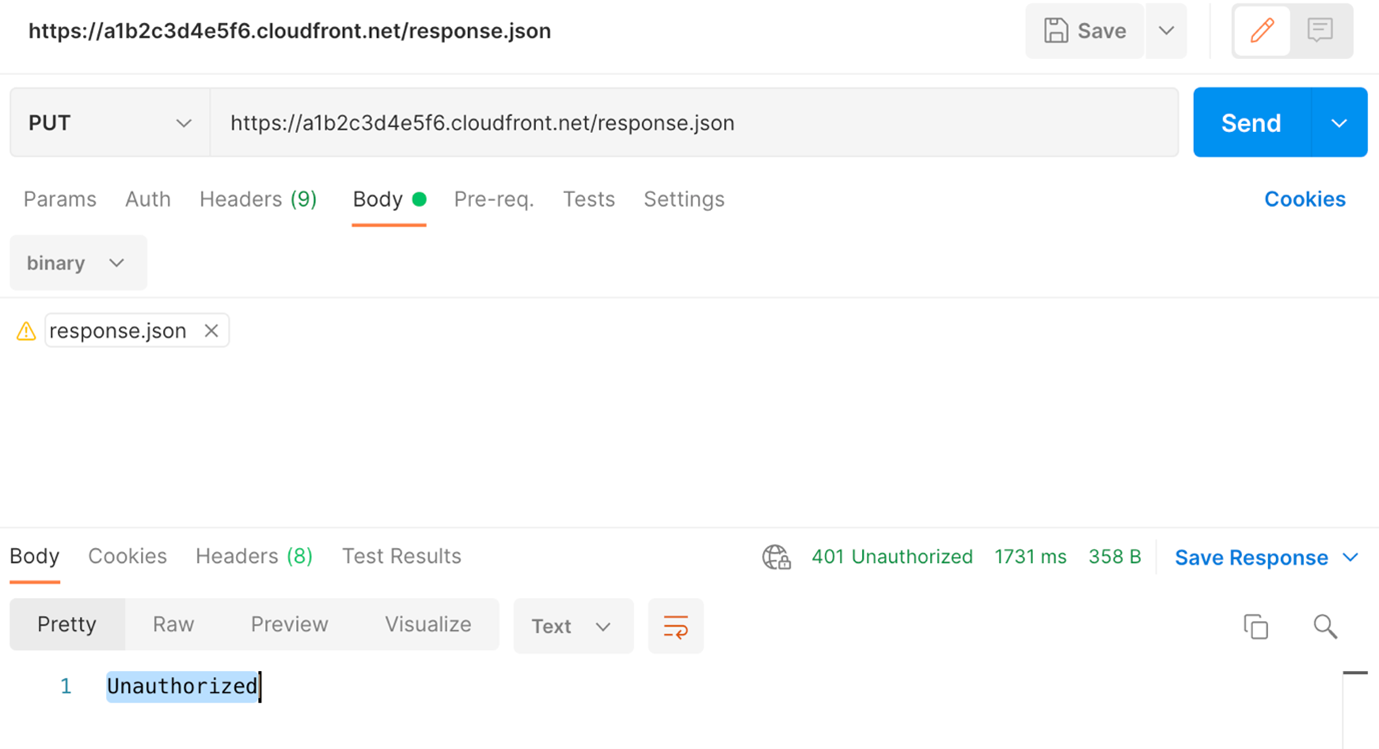
Next, verify whether direct access to the API Gateway API endpoint is blocked.
Copy your API Gateway endpoint URL and append /prod/pets to it, then open the URL in a new browser tab or window. The result should look similar to the following, which confirms that direct viewer access through API Gateway is blocked.
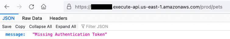
Figure 5: API error response when attempting to access API Gateway directly
Step 6: Review CloudFront configuration
Now that you’ve confirmed that access to the API Gateway endpoint is restricted to CloudFront only, you will review the CloudFront configuration that enables this restriction.
To review the CloudFront configuration
- In the CloudFormation console, choose the APIProtection stack. On the stack Resources tab, under the CFDistribution entry, copy the distribution ID.
- In the CloudFront console, select the distribution that has the distribution ID that you noted in the preceding step. On the Behaviors tab, select the behavior with path pattern Default (*).
- Choose Edit and scroll to the Cache key and origin requests section. You can see that Origin request policy is set to AllViewerExceptHostHeader, which allows CloudFront to forward viewer headers, cookies, and query strings to origins except the Host header. This policy is intended for use with the API Gateway origin.
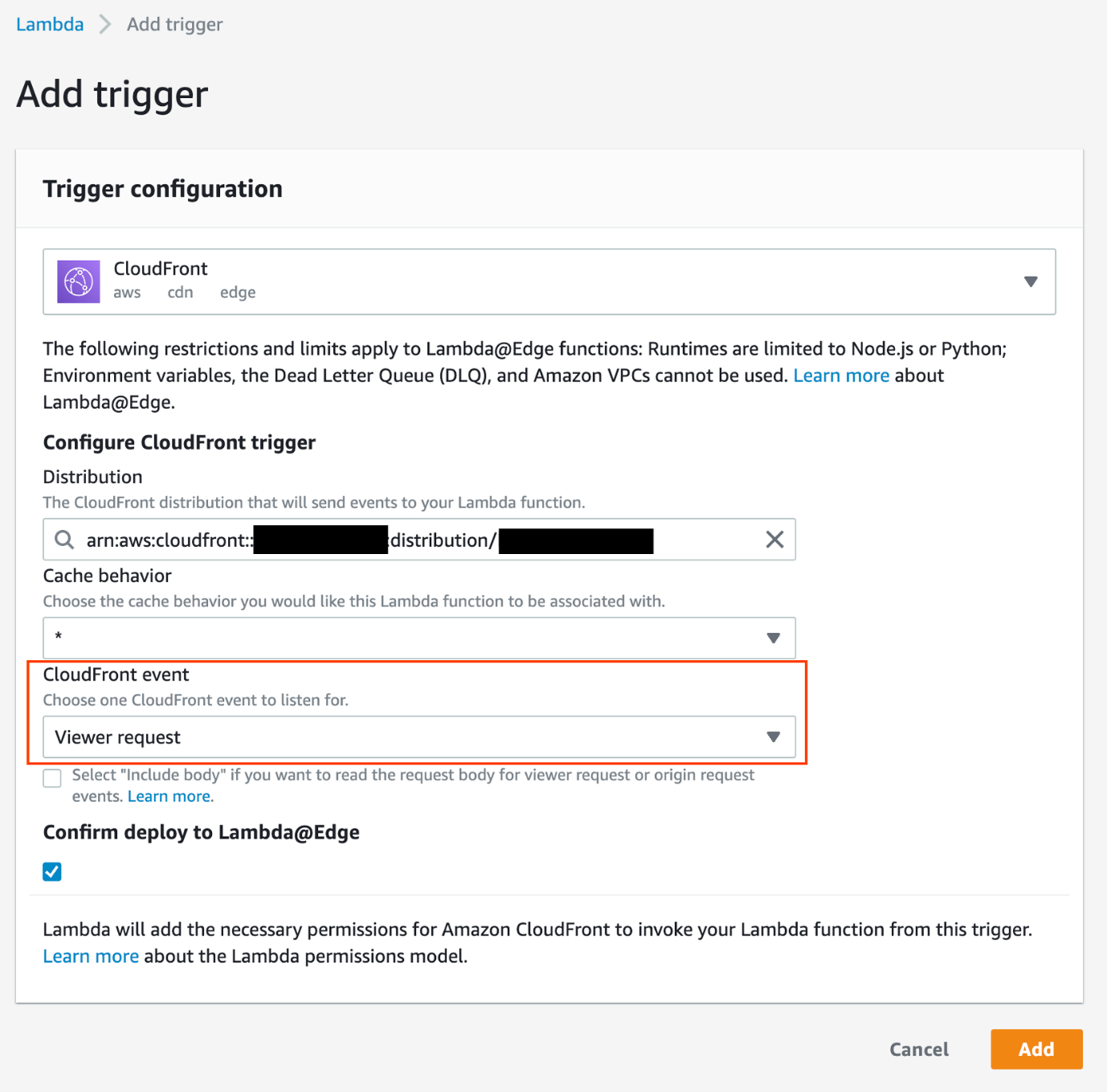
- Scroll down to the Function associations – optional section.

Figure 6: CloudFront configuration – Function association with origin request
You can see that a Lambda@Edge function is associated with the origin request event; CloudFront invokes this function before forwarding requests to the origin. You can also see that the Include body option is selected, which exposes the request body to Lambda@Edge for HTTP methods like POST/PUT, and the request payload hash will be used for Signature Version 4 signing in the Lambda@Edge function.

Step 7: Review the Lambda@Edge function and its IAM role
In this step, you will review the Lambda@Edge function code and its IAM role, and learn how the function signs the request with Signature Version 4 before forwarding to API Gateway.
To review the Lambda@Edge function code
- In the CloudFormation console, choose the APIProtection stack.
- On the stack Resources tab, choose the Sigv4RequestLambdaFunction link to go to the Lambda function, and review the function code. You can see that it follows the Signature Version 4 signing process and uses an AWS access key to calculate the signature. The AWS access key is a temporary security credential provided when the IAM role for Lambda is being assumed.
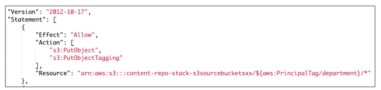
To review the IAM role for Lambda
- In the CloudFormation console, choose the APIProtection stack.
- On the stack Resources tab, choose the Sigv4RequestLambdaFunctionExecutionRole link to go to the IAM role. Expand the permission policy to review the permissions. You can see that the policy allows the API Gateway endpoint to be invoked.
Because IAM authorization is enabled, when API Gateway receives the request, it checks whether the client has execute-api:Invoke permission for the API and route before handling the request.
Step 8: Review AWS WAF web ACL configuration
In this step, you will review the web ACL configuration in AWS WAF.
AWS Managed Rules for AWS WAF helps provide protection against common application vulnerabilities or other unwanted traffic. The web ACL for this solution includes several AWS managed rule groups as an example. The Amazon IP reputation list managed rule group helps to mitigate bots and reduce the risk of threat actors by blocking problematic IP addresses. The Core rule set (CRS) managed rule group helps provide protection against exploitation of a wide range of vulnerabilities, including some of the high risk and commonly occurring vulnerabilities described in the OWASP Top 10. The Known bad inputs managed rule group helps to reduce the risk of threat actors by blocking request patterns that are known to be invalid and that are associated with exploitation or discovery of vulnerabilities, like Log4J.
AWS WAF supports rate-based rules to block requests originating from IP addresses that exceed the set threshold per 5-minute time span, until the rate of requests falls below the threshold. We have used one such rule in the following example, but you could layer the rules for better security posture. You can configure multiple rate-based rules, each with a different threshold and scope (like URI, IP list, or country) for better protection. For more information on best practices for AWS WAF rate-based rules, see The three most important AWS WAF rate-based rules.
To review the web ACL configuration
- In the CloudFormation console, choose the APIProtection stack.
- On the stack Outputs tab, choose the EdgeLayerWebACL link to go to the web ACL configuration, and then choose the Rules tab to review the rules for this web ACL. On the Rules tab, you can see that the web ACL includes the following rule and rule groups.
Figure 7: AWS WAF web ACL configuration
- Choose the Associated AWS resources tab. You should see that the CloudFront distribution is associated to this web ACL.

Step 9: (Optional) Protect the CloudFront distribution with Shield Advanced
In this optional step, you will protect your CloudFront distribution with Shield Advanced. This adds additional protection on top of the protection provided by AWS WAF managed rule groups and rate-based rules in the web ACL that is associated with the CloudFront distribution.
Note: Proceed with this step only if you have subscribed to an annual subscription to Shield Advanced.
AWS Shield is a managed DDoS protection service that is offered in two tiers: AWS Shield Standard and AWS Shield Advanced. All AWS customers benefit from the automatic protection of Shield Standard, at no additional cost. Shield Standard helps defend against the most common, frequently occurring network and transport layer DDoS attacks that target your website or applications. AWS Shield Advanced is a paid service that requires a 1-year commitment—you pay one monthly subscription fee, plus usage fees based on gigabytes (GB) of data transferred out. Shield Advanced provides expanded DDoS attack protection for your applications.
Besides providing visibility and additional detection and mitigation against large and sophisticated DDoS attacks, Shield Advanced also gives you 24/7 access to the Shield Response Team (SRT) and cost protection against spikes in your AWS bill that might result from a DDoS attack against your protected resources. When you use both Shield Advanced and AWS WAF to help protect your resources, AWS waives the basic AWS WAF fees for web ACLs, rules, and web requests for your protected resources. You can grant permission to the SRT to act on your behalf, and also configure proactive engagement so that SRT contacts you directly when the availability and performance of your application is impacted by a possible DDoS attack.
Shield Advanced automatic application-layer DDoS mitigation compares current traffic patterns to historic traffic baselines to detect deviations that might indicate a DDoS attack. When you enable automatic application-layer DDoS mitigation, if your protected resource doesn’t yet have a history of normal application traffic, we recommend that you set to Count mode until a history of normal application traffic has been established. Shield Advanced establishes baselines that represent normal traffic patterns after protecting resources for at least 24 hours and is most accurate after 30 days. To mitigate against application layer attacks automatically, change the AWS WAF rule action to Block after you’ve established a normal traffic baseline.
To help protect your CloudFront distribution with Shield Advanced
- In the WAF & Shield console, in the AWS Shield section, choose Protected Resources, and then choose Add resources to protect.
- For Resource type, select CloudFront distribution, and then choose Load resources.
- In the Select resources section, select the CloudFront distribution that you used in Step 6 of this post. Then choose Protect with Shield Advanced.
- In the Automatic application layer DDoS mitigation section, choose Enable. Leave the AWS WAF rule action as Count, and then choose Next.
- (Optional, but recommended) Under Associated health check, choose one Amazon Route 53 health check to associate with the protection, and then choose Next. The Route 53 health check is used to enable health-based detection, which can improve responsiveness and accuracy in attack detection and mitigation. Associating the protected resource with a Route 53 health check is also one of the prerequisites to be protected with proactive engagement. You can create the health check by following these best practices.
- (Optional) In the Select SNS topic to notify for DDoS detected alarms section, select the SNS topic that you want to use for notification for DDoS detected alarms, then choose Next.
- Choose Finish configuration.
With automatic application-layer DDoS mitigation configured, Shield Advanced creates a rule group in the web ACL that you have associated with your resource. Shield Advanced depends on the rule group for automatic application-layer DDoS mitigation.
To review the rule group created by Shield Advanced
- In the CloudFormation console, choose the APIProtection stack. On the stack Outputs tab, look for the EdgeLayerWebACL entry.
- Choose the EdgeLayerWebACL link to go to the web ACL configuration.
- Choose the Rules tab, and look for the rule group with the name that starts with ShieldMitigationRuleGroup, at the bottom of the rule list. This rule group is managed by Shield Advanced, and is not viewable.
Figure 8: Shield Advanced created rule group for DDoS mitigation

Considerations
Here are some further considerations as you implement this solution:
- To limit API access to only authenticated users, use the edge computing capabilities of CloudFront. For example, use Lambda@Edge to secure a CloudFront distribution by using OpenID Connect, or use CloudFront functions for JSON web token validation.
- Lambda@Edge functions are run in a regional edge cache, which is usually in the AWS Region closest to the CloudFront edge location that is reached by the client. You must pay attention to the scaling limit of Lambda@Edge, and request a higher quota if needed.
Conclusion
In this blog post, we introduced managing public-facing APIs through API Gateway, and helping protect API Gateway endpoints by using CloudFront and AWS perimeter protection services (AWS WAF and Shield Advanced). We walked through the steps to add Signature Version 4 authentication information to the CloudFront originated API requests, providing trusted access to the APIs. Together, these actions present a best practice approach to build a DDoS-resilient architecture that helps protect your application’s availability by preventing many common infrastructure and application layer DDoS attacks.
If you have feedback about this post, submit comments in the Comments section below. If you have questions about this post, contact AWS Support.
Want more AWS Security news? Follow us on Twitter.


 Corey Johnson is the Lead Data Architect at Huron, where he leads its data architecture for their Global Products Data and Analytics initiatives.
 Sakti Mishra is a Principal Data Analytics Architect at AWS, where he helps customers modernize their data architecture, help define end to end data strategy including data security, accessibility, governance, and more. He is also the author of the book


 Abhi Sodhani is a Sr. AI/ML Solutions Architect at AWS. He helps customers with a wide range of solutions, including machine leaning, artificial intelligence, data lakes, data warehousing, and data visualization. Outside of work, he is passionate about books, yoga, and travel.


 David Zhang is an AWS Data Architect in Global Financial Services. He specializes in designing and implementing serverless analytics infrastructure, data management, ETL, and big data systems. He helps customers modernize their data platforms on AWS. David is also an active speaker and contributor to AWS conferences, technical content, and open-source initiatives. During his free time, he enjoys playing volleyball, tennis, and weightlifting. Feel free to connect with him on
  Manash Deb is a Software Development Manager in the AWS Directory Service team. With over 18 years of software dev experience, his passion is designing and delivering highly scalable, secure, zero-maintenance applications in the AWS identity and data analytics space. He loves mentoring and coaching others and to act as a catalyst and force multiplier, leading highly motivated engineering teams, and building large-scale distributed systems.
 Pavan Kumar Vadupu Lakshman Manikya is an AWS Solutions Architect who helps customers design robust, scalable solutions across multiple industries. With a background in enterprise architecture and software development, Pavan has contributed in creating solutions to handle API security, API management, microservices, and geospatial information system use cases for his customers. He is passionate about learning new technologies and solving, automating, and simplifying customer problems using these solutions.


