Tag Archives: Amazon API Gateway

Invoking asynchronous external APIs with AWS Step Functions

Post Syndicated from Jorge Fonseca original https://aws.amazon.com/blogs/architecture/invoking-asynchronous-external-apis-with-aws-step-functions/

External vendor APIs can help organizations streamline operations, reduce costs, and provide better services to their customers. But many challenges exist in integrating with third-party services such as security, reliability, and cost.

Organizations must ensure their systems can handle performance issues or downtime. In some cases, calling an external API may have associated costs such as licensing fees. If a contract exists with the external API vendor to adhere to maximum Requests Per Second (RPS), the system needs to adapt accordingly.

In this blog post, we show you how to build an architecture to invoke an external vendor API using AWS Step Functions, with specific guidance on reliability.

This orchestration is applicable to any industry that relies on technology and data benefitting from external vendor API integration. Examples include e-commerce applications for online retailers integrating with third-party payment gateways, shipping carriers, or applications in the healthcare and banking sectors.

Invoking asynchronous external APIs overview

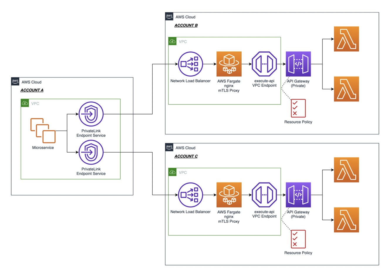
This solution outlines the use of AWS services to build an orchestrator controlling the invocation rate of third-party services that implement the service callback pattern to process long-running jobs. This architecture is also available in the AWS Reference Architecture Diagrams section of the AWS Architecture Center.

As in Figure 1, the architecture gives you the control to feed your calls to an external service according to its maximum RPS contract using Step Functions capabilities. Step Functions pauses main request workflows until you receive a callback from the external system indicating job completion.

Invoking Asynchronous External APIs architecture

Figure 1. Invoking Asynchronous External APIs architecture

Let’s explore each step.

  1. Set up Step Functions to handle the lifecycle of long-running requests to the third party. Inside the workflow, add a request step that pauses it using waitForTaskToken as a callback to continue. Set a timeout to throw a timeout error if a callback isn’t received.
  2. Send the task token and request payload to an Amazon Simple Queue Service (Amazon SQS) queue. Use Amazon CloudWatch to monitor its length. Consider adjusting the contract with the third-party service if the queue length grows beyond a soft limit determined on the maximum RPS with the third party.
  3. Use AWS Lambda to poll Amazon SQS and trigger an express Step Functions workflow. Control the invocation rate of Lambda using polling batch size, reserved concurrency, and maximum concurrency, discussed in more detail later in the blog.
  4. Optionally, add dynamic delay inside Lambda controlled by AWS AppConfig if the system still needs a lower invocation rate to comply with the contracted RPS.
  5. Step Functions invokes an Amazon API Gateway HTTP proxy API configured with rate limit to comply with the contracted RPS. API Gateway is a safeguard proxy to make sure your system is not breaking the RPS contract while dynamically adjusting the invocation rate parameters.
  6. Invoke the external third-party asynchronous service API sending the payload consumed from the requests queue and receiving the jobID from the service. Send failed requests to the Dead Letter Queue (DLQ) using Amazon SQS.
  7. Store the main workflow’s task token and jobID from the third-party service in an Amazon DynamoDB table. This is used as a mapping to correlate the jobID with the task token.
  8. When the external service completes, receive the completed jobID in a callback webhook endpoint implemented with API Gateway.
  9. Transform the external callbacks with API Gateway mapping templates, add the payload and jobID to an Amazon SQS queue, and respond immediately to the caller.
  10. Use Lambda to poll the callback Amazon SQS queue, then query the token stored. Use the token to unblock the waiting workflow by calling SendTaskSuccess and the callback DLQ to store failed messages.
  11. On the main workflow, pass the jobID to the next step and invoke a Step Functions processor to fetch the third-party results. Finally, process the external service’s results.

Controlling external API invocation rates

To comply with third-party RPS contracts, adopt a mechanism to control your system’s invocation rate. The rate of polling the messages from the request Amazon SQS (or step 3 in the architecture) directly impacts your invocation rate.

Different parameters can be used to control the invocation rate for Lambda with Amazon SQS as its trigger “event source,” such as:

  1. Batch size: The number of records to send to the function in each batch. For a standard queue, this can be up to 10,000 records. For a first-in, first-out (FIFO) queue, the maximum is 10. Using batch size on its own will not limit the invocation rate. It should be used in conjunction with other parameters such as reserved concurrency or maximum concurrency.
  2. Batch window: The maximum amount of time to gather records before invoking the function, in seconds. This applies only to standard queues.
  3. Maximum concurrency: Sets limits on the number of concurrent instances of the function that an Amazon SQS event source can invoke. Maximum concurrency is an event source-level setting.

Trigger configuration is shown in Figure 2.

Configuration parameters for triggering Lambda

Figure 2. Configuration parameters for triggering Lambda

Other Lambda configuration parameters can also be used to control the invocation rate, such as:

  1. Reserved concurrency: Guarantees the maximum number of concurrent instances for the function. When a function has reserved concurrency, no other function can use that concurrency. This can be used to limit and reduce the invocation rate.
  2. Provisioned concurrency: Initializes a requested number of execution environments so that they are prepared to respond immediately to your function’s invocations. Note that configuring provisioned concurrency incurs charges to your AWS account.

These additional Lambda configuration parameters are shown here in Figure 3.

Lambda concurrency configuration options - Reserved and Provisioned

Figure 3. Lambda concurrency configuration options – Reserved and Provisioned

Maximizing your external API architecture

During this architecture implementation, consider some use cases to ensure that you are building a mature orchestrator.

Let’s explore some examples:

  • If the external system fails to respond to the API request in step 8, a timeout exception will occur at step 1. A sensible timeout should be configured in the main state machine in step 1. The timeout value should consider the maximum response time of the external system.

The Error handling capabilities in Step Functions section of the AWS Step Functions Developer Guide provides the ability to implement your own logic for different error types. Configure timeout errors using the States.Timeout error state.

  • Dynamic delay inside the Lambda function—as mentioned in step 4—should only be used temporarily for burst traffic. If the external party has a very low RPS contract, consider other alternatives to introduce delay.

For example, Amazon EventBridge Scheduler can be used to trigger the Lambda function at regular intervals to consume the messages from Amazon SQS. This avoids costs for the idle/waiting state of your Lambda functions.

Conclusion

This blog post discusses how to build end-to-end orchestration to manage a request’s lifecycle, five different parameters to control invocation rate of third-party services, and throttle calls to external service API per maximum RPS contract.

We also consider use cases on using error handling capabilities in Step Functions and monitor systems with CloudWatch. In addition, this architecture adopts fully managed AWS Serverless services, removing the undifferentiated heavy lifting in building highly available, reliable, secure, and cost-effective systems in AWS.

Managing sessions of anonymous users in WebSocket API-based applications

Post Syndicated from James Beswick original https://aws.amazon.com/blogs/compute/managing-sessions-of-anonymous-users-in-websocket-api-based-applications/

This post is written by Alexey Paramonov, Solutions Architect, ISV.

This blog post demonstrates how to reconnect anonymous users to WebSocket API without losing their session context. You learn how to link WebSocket API connection IDs to the logical user, what to do when the connection fails, and how to store and recover session information when the user reconnects.

WebSocket APIs are common in modern interactive applications. For example, for watching stock prices, following live chat feeds, collaborating with others in productivity tools, or playing online games. Another example described in “Implementing reactive progress tracking for AWS Step Functions” blog post uses WebSocket APIs to send progress back to the client.

The backend is aware of the client’s connection ID to find the right client to send data to. But if the connection temporarily fails, the client reconnects with a new connection ID. If the backend does not have a mechanism to associate a new connection ID with the same client, the interaction context is lost and the user must start over again. In a live chat feed that could mean skipping to the most recent message with a loss of some previous messages. And in case of AWS Step Functions progress tracking the user would lose progress updates.

Overview

The sample uses Amazon API Gateway WebSocket APIs. It uses AWS Lambda for WebSocket connection management and for mocking a teleprinter to generate a stateful stream of characters for testing purposes. There are two Amazon DynamoDB tables for storing connection IDs and user sessions, as well as an optional MediaWiki API for retrieving an article.

The following diagram outlines the architecture:

Reference architecture

  1. The browser generates a random user ID and stores it locally in the session storage. The client sends the user ID inside the Sec-WebSocket-Protocol header to WebSocket API.
  2. The default WebSocket API route OnConnect invokes OnConnect Lambda function and passes the connection ID and the user ID to it. OnConnect Lambda function determines if the user ID exists in the DynamoDB table and either creates a new item or updates the existing one.
  3. When the connection is open, the client sends the Read request to the Teleprinter Lambda function.
  4. The Teleprinter Lambda function downloads an article about WebSocket APIs from Wikipedia and stores it as a string in memory.
  5. The Teleprinter Lambda function checks if there is a previous state stored in the Sessions table in DynamoDB. If it is a new user, the Teleprinter Lambda function starts sending the article from the beginning character by character back to the client via WebSocket API. If it is a returning user, the Teleprinter Lambda function retrieves the last cursor position (the last successfully sent character) from the DynamoDB table and continues from there.
  6. The Teleprinter Lambda function sends 1 character every 100ms back to the client.
  7. The client receives the article and prints it out character by character as each character arrives.
  8. If the connection breaks, the WebSocket API calls the OnDisconnect Lambda function automatically. The function marks the connection ID for the given user ID as inactive.
  9. If the user does not return within 5 minutes, Amazon EventBridge scheduler invokes the OnDelete Lambda function, which deletes items with more than 5 minutes of inactivity from Connections and Sessions tables.

A teleprinter returns data one character at a time instead of a single response. When the Lambda function fetches an article, it feeds it character by character inside the for-loop with a delay of 100ms on every iteration. This demonstrates how the user can continue reading the article after reconnecting and not starting the feed all over again. The pattern could be useful for traffic limiting by slowing down user interactions with the backend.

Understanding sample code functionality

When the user connects to the WebSocket API, the client generates a user ID and saves it in the browser’s session storage. The user ID is a random string. When the client opens a WebSocket connection, the frontend sends the user ID inside the Sec-WebSocket-Protocol header, which is standard for WebSocket APIs. When using the JavaScript WebSocket library, there is no need to specify the header manually. To initialize a new connection, use:

const newWebsocket = new WebSocket(wsUri, userId);

wsUri is the deployed WebSocket API URL and userId is a random string generated in the browser. The userId goes to the Sec-WebSocket-Protocol header because WebSocket APIs generally offer less flexibility in choosing headers compared to RESTful APIs. Another way to pass the user ID to the backend could be a query string parameter.

The backend receives the connection request with the user ID and connection ID. The WebSocket API generates the connection ID automatically. It’s important to include the Sec-WebSocket-Protocol in the backend response, otherwise the connection closes immediately:

    return {
        'statusCode': 200,
        'headers': {
            'Sec-WebSocket-Protocol': userId
        }
    }

The Lambda function stores this information in the DynamoDB Connections table:

    ddb.put_item(
        TableName=table_name,
        Item={
            'userId': {'S': userId},
            'connectionId': {'S': connection_id},
            'domainName': {'S': domain_name},
            'stage': {'S': stage},
            'active': {'S': True}
        }
    )

The active attribute indicates if the connection is up. In the case of inactivity over a specified time limit, the OnDelete Lambda function deletes the item automatically. The Put operation comes handy here because you don’t need to query the DB if the user already exists. If it is a new user, Put creates a new item. If it is a reconnection, Put updates the connectionId and sets active to True again.

The primary key for the Connections table is userId, which helps locate users faster as they reconnect. The application relies on a global secondary index (GSI) for locating connectionId. This is necessary for marking the connection inactive when WebSocket API calls OnDisconnect function automatically.

Now the application has connection management, you can retrieve session data. The Teleprinter Lambda function receives a connection ID from WebSocket API. You can query the GSI of Connections table and find if the user exists:

    def get_user_id(connection_id):
        response = ddb.query(
            TableName=connections_table_name,
            IndexName='connectionId-index',
            KeyConditionExpression='connectionId = :c',
            ExpressionAttributeValues={
                ':c': {'S': connection_id}
            }
        )

        items = response['Items']

        if len(items) == 1:
            return items[0]['userId']['S']

        return None

Another DynamoDB table called Sessions is used to check if the user has an existing session context. If yes, the Lambda function retrieves the cursor position and resumes teletyping. If it is a brand-new user, the Lambda function starts sending characters from the beginning. The function stores a new cursor position if the connection breaks. This makes it easier to detect stale connections and store the current cursor position in the Sessions table.

    Try:
        api_client.post_to_connection(
            ConnectionId=connection_id,
            Data=bytes(ch, 'utf-8')
        )
    except api_client.exceptions.GoneException as e:
        print(f"Found stale connection, persisting state")
        store_cursor_position(user_id, pos)
        return {
            'statusCode': 410
        }

    def store_cursor_position(user_id, pos):
        ddb.put_item(
            TableName=sessions_table_name,
            Item={
                'userId': {'S': user_id},
                'cursorPosition': {'N': str(pos)}
            }
        )

After this, the Teleprinter Lambda function ends.

Serving authenticated users

The same mechanism also works for authenticated users. The main difference is it takes a given ID from a JWT token or other form of authentication and uses it instead of a randomly generated user ID. The backend relies on unambiguous user identification and may require only minor changes for handling authenticated users.

Deleting inactive users

The OnDisconnect function marks user connections as inactive and adds a timestamp to ‘lastSeen’ attribute. If the user never reconnects, the application should purge inactive items from Connections and Sessions tables. Depending on your operational requirements, there are two options.

Option 1: Using EventBridge Scheduler

The sample application uses EventBridge to schedule OnDelete function execution every 5 minutes. The following code shows how AWS SAM adds the scheduler to the OnDelete function:

  OnDeleteSchedulerFunction:
    Type: AWS::Serverless::Function
    Properties:
      Handler: app.handler
      Runtime: python3.9
      CodeUri: handlers/onDelete/
      MemorySize: 128
      Environment:
        Variables:
          CONNECTIONS_TABLE_NAME: !Ref ConnectionsTable
          SESSIONS_TABLE_NAME: !Ref SessionsTable
      Policies:
      - DynamoDBCrudPolicy:
          TableName: !Ref ConnectionsTable
      - DynamoDBCrudPolicy:
          TableName: !Ref SessionsTable
      Events:
        Schedule:
          Type: ScheduleV2
          Properties:
            ScheduleExpression: rate(5 minute)

The Events section of the function definition is where AWS SAM sets up the scheduled execution. Change values in ScheduleExpression to meet your scheduling requirements.

The OnDelete function relies on the GSI to find inactive user IDs. The following code snippet shows how to query connections with more than 5 minutes of inactivity:

    five_minutes_ago = int((datetime.now() - timedelta(minutes=5)).timestamp())

    stale_connection_items = table_connections.query(
        IndexName='lastSeen-index',
        KeyConditionExpression='active = :hk and lastSeen < :rk',
        ExpressionAttributeValues={
            ':hk': 'False',
            ':rk': five_minutes_ago
        }
    )

After that, the function iterates through the list of user IDs and deletes them from the Connections and Sessions tables:

    # remove inactive connections
    with table_connections.batch_writer() as batch:
        for item in inactive_users:
            batch.delete_item(Key={'userId': item['userId']})

    # remove inactive sessions
    with table_sessions.batch_writer() as batch:
        for item in inactive_users:
            batch.delete_item(Key={'userId': item['userId']})

The sample uses batch_writer() to avoid requests for each user ID.

Option 2: Using DynamoDB TTL

DynamoDB provides a built-in mechanism for expiring items called Time to Live (TTL). This option is easier to implement. With TTL, there’s no need for EventBridge scheduler, OnDelete Lambda function and additional GSI to track time span. To set up TTL, use the ‘lastSeen’ attribute as an object creation time. TTL deletes or archives the item after a specified period of time. When using AWS SAM or AWS CloudFormation templates, add TimeToLiveSpecification to your code.

The TTL typically deletes expired items within 48 hours. If your operational requirements demand faster and more predictable timing, use option 1. For example, if your application aggregates data while the user is offline, use option 1. But if your application stores a static session data, like cursor position used in this sample, option 2 can be an easier alternative.

Deploying the sample

Prerequisites

Ensure you can manage AWS resources from your terminal.

  • AWS CLI and AWS SAM CLI installed.
  • You have an AWS account. If not, visit this page.
  • Your user has enough permissions to manage AWS resources.
  • Git is installed.
  • NPM is installed (only for local frontend deployment).

You can find the source code and README here.

The repository contains both the frontend and the backend code. To deploy the sample, follow this procedure:

  1. Open a terminal and clone the repository:
    git clone https://github.com/aws-samples/websocket-sessions-management.git
  2. Navigate to the root of the repository.
  3. Build and deploy the AWS SAM template:
    sam build && sam deploy --guided
  4. Note the value of WebSocketURL in the output. You need it later.

With the backend deployed, test it using the hosted frontend.

Testing the application

Testing the application

You can watch an animated demo here.

Notice that the app has generated a random user ID on startup. The app shows the user ID above in the header.

  1. Paste the WebSocket URL into the text field. You can find the URL in the console output after you have successfully deployed your AWS SAM template. Alternatively, you can navigate to AWS Management Console (make sure you are in the right Region), select the API you have recently deployed, go to “Stages”, select the deployed stage and copy the “WebSocket URL” value.
  2. Choose Connect. The app opens a WebSocket connection.
  3. Choose Tele-read to start receiving the Wikipedia article character by character. New characters appear in the second half of the screen as they arrive.
  4. Choose Disconnect to close WebSocket connection. Reconnect again and choose Tele-read. Your session resumes from where you stopped.
  5. Choose Reset Identity. The app closes the WebSocket connection and changes the user ID. Choose Connect and Tele-read again and your character feed starts from the beginning.

Cleaning up

To clean up the resources, in the root directory of the repository run:

sam delete

This removes all resources provisioned by the template.yml file.

Conclusion

In this post, you learn how to keep track of user sessions when using WebSockets API and not lose the session context when the user reconnects again. Apply learnings from this example to improve your user experience when using WebSocket APIs for web-frontend and mobile applications, where internet connections may be unstable.

For more serverless learning resources, visit  Serverless Land.

Access Amazon Athena in your applications using the WebSocket API

Post Syndicated from Abhi Sodhani original https://aws.amazon.com/blogs/big-data/access-amazon-athena-in-your-applications-using-the-websocket-api/

Modern applications are built with modular independent components or microservices that rely on an API framework to communicate with services. Many organizations are building data lakes to store and analyze large volumes of structured, semi-structured, and unstructured data. In addition, many teams are moving towards a data mesh architecture, which requires them to expose their data sets as easily consumable data products. To accomplish this on AWS, organizations use Amazon Simple Storage Service (Amazon S3) to provide cheap and reliable object storage to house their datasets. To enable interactive querying and analyzing their data in place using familiar SQL syntax, many teams are turning to Amazon Athena. Athena is an interactive query service that is used by modern applications to query large volumes of data on an S3 data lake using standard SQL.

When working with SQL databases, application developers and business analysts are most familiar with simple permissions management and synchronous query-response protocols—if a user has permissions to submit a query, they do so and receive the results from the server when the query is complete. Directly accessing Athena APIs, for example when integrating with a custom web application, requires an AWS Identity and Access Management (IAM) role for the applications, and requires you to build a custom process to poll for query completion asynchronously. The IAM role needs access to run Athena API calls, as well as S3 permissions to retrieve the Athena output stored on Amazon S3. Polling for Athena query completion when performed at several intervals could result in increased latency from the client perspective.

In this post, we present a solution that can integrate with your front-end application to query data from Amazon S3 using an Athena synchronous API invocation. With this solution, you can add a layer of abstraction to your application on direct Athena API calls and promote the access using the WebSocket API developed with Amazon API Gateway. The query results are returned back to the application as Amazon S3 presigned URLs.

Overview of solution

For illustration purposes, this post builds a COVID-19 data lake with a WebSocket API to handle Athena queries. Your application can invoke the WebSocket API to pull the data from Amazon S3 using an Athena SQL query, and the WebSocket API returns the JSON response with the presigned Amazon S3 URL. The application needs to parse the JSON message to read the presigned URL, download the data to local, and report the data back to the front end.

We use AWS Step Functions to poll the Athena query run. When the query is complete, Step Functions invokes an AWS Lambda function to generate the presigned URL and send the request back to the application.

The application doesn’t require direct access to Athena, just access to invoke the API. When using this solution, you should secure the API following AWS guidelines. For more information, refer to Controlling and managing access to a WebSocket API in API Gateway.

The following diagram summarizes the architecture, key components, and interactions in the solution.

Architecture diagram for the Athena WebSocket API. The user connects to the API through API Gateway. API Gateway uses Lambda and DynamoDB to store session data. SQL queries are routed to Amazon Athena and a Step Function polls for query status and returns the results back to the user.

The application is composed of the WebSocket API in API Gateway, which handles the connectivity between the client and Athena. A client application using the framework can submit the Athena SQL query and get back the presigned URL containing the query results data. The workflow includes the following steps:

  1. The application invokes the WebSocket API connection.
  2. A Lambda function is invoked to initiate the connection. The connection ID is stored in an Amazon DynamoDB
  3. When the client application is connected, it can invoke the runquery action, which invokes the RunQuery Lambda function.
  4. The function first runs the Athena query.
  5. When the query is started, the function checks the status and uses Step Functions to track the query progress.
  6. Step Functions invokes the third Lambda function to read the processed Athena results and get the presigned S3 URL. Failed messages are routed to an Amazon Simple Notification Service (Amazon SNS) topic, which you can subscribe to.
  7. The presigned URL is returned to the client application.
  8. The connection is closed using the OnDisconnect function.

The RunQuery Lambda function runs the Athena query using the start_query_execution request:

def run_query(client, query):
    """This function executes and sends the query request to Athena."""
    response = client.start_query_execution(
        QueryString=query,
        QueryExecutionContext={
            'Database': params['Database']
        },
        ResultConfiguration={
            'OutputLocation': f's3://{params["BucketName"]}/{params["OutputDir"]}/'
        },
        WorkGroup=params["WorkGroup"]
    )
    return response

The Amazon S3 presigned URL is generated by invoking the generate_presigned_url request with the bucket and key information that hosts the Athena results. The code hard codes the presigner expiration to 120 seconds, which is configurable in the function input parameter PreSignerExpireSeconds. See the following code:

def signed_get_url(event):
    s3 = boto3.client('s3', region_name=params['Region'], config=Config(signature_version='s3v4'))
    # User provided body with object info
    bodyData = json.loads(event['body'])
    try:
        url = s3.generate_presigned_url(
            ClientMethod='get_object',
            Params={
                'Bucket': params['BucketName'],
                'Key': bodyData["ObjectName"]
            },
            ExpiresIn=int(params['PreSignerExpireSeconds'])
        )
        body = {'PreSignedUrl': url, 'ExpiresIn': params['PreSignerExpireSeconds']}
        response = {
            'statusCode': 200,
			'body': json.dumps(body),
            'headers': cors.global_returns["Allow Origin Header"]
        }
        logger.info(f"[MESSAGE] Response for PreSignedURL: {response}")
    except Exception as e:
        logger.exception(f"[MESSAGE] Unable to generate URL: {str(e)}")
        response = {
            'statusCode': 502,
            'body': 'Unable to generate PreSignedUrl',
            'headers': cors.global_returns["Allow Origin Header"]
        }
    return response

Prerequisites

This post assumes you have the following:

  • Access to an AWS account
  • Permissions to create an AWS CloudFormation stack
  • Permissions to create the following resources:
    • AWS Glue catalog databases and tables
    • API Gateway
    • Lambda function
    • IAM roles
    • Step Functions state machine
    • SNS topic
    • DynamoDB table

Enable the WebSocket API

To enable the WebSocket API of API Gateway, complete the following steps:

  1. Configure the Athena dataset.

To make the data from the AWS COVID-19 data lake available in the Data Catalog in your AWS account, create a CloudFormation stack using the following template. If you’re signed in to your AWS account, the following page fills out most of the stack creation form for you. All you need to do is choose Create stack. For instructions on creating a CloudFormation stack, see Getting started with AWS CloudFormation.

You can also use an existing Athena database to query, in which case you need to update the stack parameters.

  1. Sign in to the Athena console.

If this is the first time you’re using Athena, you must specify a query result location on Amazon S3. For more information about querying and accessing the data from Athena, see A public data lake for analysis of COVID-19 data.

  1. Configure the WebSocket framework using the following page, which deploys the API infrastructure using AWS Serverless Application Model (AWS SAM).
  2. Update the parameters pBucketName with the S3 bucket (in the us-east-2 region) that stores the Athena results and also update the database if you want to query an existing database.
  3. Select the check box to acknowledge creation of IAM roles and choose Deploy.

At a high level, these are the primary resources deployed by the application template:

  • An API Gateway with routes to the connect, disconnect, and query Lambda functions. Note that the API Gateway deployed with this sample doesn’t implement authentication and authorization. We recommend that you implement authentication and authorization before deploying into a production environment. Refer to Controlling and managing access to a WebSocket API in API Gateway to understand how to implement these security controls.
  • A DynamoDB table for tracking client connections.
  • Lambda functions to manage connection states using DynamoDB.
  • A Lambda function to run the query and start the step function. The function includes an associated IAM role and policies with permissions to Step Functions, the AWS Glue Data Catalog, Athena, AWS Key Management Service (AWS KMS), and Amazon S3. Note that the Lambda execution role gives read access to the Data Catalog and S3 bucket that you specify in the deployment parameters. We recommend that you don’t include a catalog that contains sensitive data without first understanding the impacts and implementing additional security controls.
  • A Lambda function with associated permissions to poll for the query results and return the presigned URL to the client.
  • A Step Functions state machine with associated permissions to run the polling Lambda function and send API notifications using Amazon SNS.

Test the setup

To test the WebSocket API, you can use wscat, an open-source command line tool.

  1. Install NPM.
  2. Install wscat:
$ npm install -g wscat
  1. On the console, connect to your published API endpoint by running the following command. The full URI to use can be found on the AWS CloudFormation console by finding the WebSocketURI output in the serverlessrepo-aws-app-athena-websocket-integration stack that was deployed by the AWS SAM application you deployed previously.
$ wscat -c wss://{YOUR-API-ID}.execute-api.{YOUR-REGION}.amazonaws.com/{STAGE}
  1. To test the runquery function, send a JSON message like the following example. This triggers the state machine to run your SQL query using Athena and, using Lambda, return an S3 presigned URL to your client, which you can access to download the query results. Note that the API accepts any valid Athena query. Additional query validation could be added to the internal Lambda function if desired.
$ wscat -c wss://{YOUR-API-ID}.execute-api.{YOUR-REGION}.amazonaws.com/{STAGE}
Connected (press CTRL+C to quit)
> {"action":"runquery", "data":"SELECT * FROM \"covid-19\".country_codes limit 5"}
< {"pre-signed-url": "https://xxx-s3.amazonaws.com/athena_api_access_results/xxxxx.csv?"}
  1. Copy the value for pre-signed-url and enter it into your browser window to access the results.

The presigned URL provides you temporary credentials to download the query results. For more information, refer to Using presigned URLs. This process can be integrated into a front-end web application to automatically download and display the results of the query.

Clean up

To avoid incurring ongoing charges, delete the resources you provisioned by deleting the CloudFormation stacks CovidLakeStacks and serverlessrepo-AthenaWebSocketIntegration via the AWS CloudFormation console. For detailed instructions, refer to the cleanup sections in the starter kit README files in the GitHub repo.

Conclusion

In this post, we showed how to integrate your application with Athena using the WebSocket API. We have included a GitHub repo for you to understand the code and modify it per your application requirements, to get the full benefits of the solution. We encourage you to further explore the features of the API Gateway WebSocket API to add in security using authorizers, view live invocations using dashboards, and expand the framework for more routes on action request.

Let’s stay in touch via the GitHub repo.


About the Authors

Abhi Sodhani is a Sr. AI/ML Solutions Architect at AWS. He helps customers with a wide range of solutions, including machine leaning, artificial intelligence, data lakes, data warehousing, and data visualization. Outside of work, he is passionate about books, yoga, and travel.

Robin Zimmerman's HeadshotRobin Zimmerman is a Data and ML Engineer with AWS Professional Services. He works with AWS enterprise customers to develop systems to extract value from large volumes of data using AWS data, analytics, and machine learning services. When he’s not working, you’ll probably find him in the mountains—rock climbing, skiing, mountain biking, or out on whatever other adventure he can dream up.

Content Repository for Unstructured Data with Multilingual Semantic Search: Part 1

Post Syndicated from Patrik Nagel original https://aws.amazon.com/blogs/architecture/content-repository-for-unstructured-data-with-multilingual-semantic-search-part-1/

Unstructured data can make up to 80 percent of data in the day-to-day business of financial organizations. For example, these organizations typically store and read PDFs and images for claim processing, underwriting, and know your customer (KYC). Organizations need to make this ingested data accessible and searchable across different entities while logically separating data access according to role requirements.

In this two-part series, we use AWS services to build an end-to-end content repository for storing and processing unstructured data with the following features:

  • Dynamic access control-based logic over unstructured data
  • Multilingual semantic search capabilities

In part 1, we build the architectural foundation for the content repository, including the resource access control logic and a web UI to upload and list documents.

Solution overview

The content repository includes four building blocks:

Frontend and interaction: For this function, we use AWS Amplify, which is a set of purpose-built tools and features to help frontend web and mobile developers quickly build full-stack applications on AWS. The React application uses the AWS Amplify authentication feature to quickly set up a complete authentication flow integrated into Amazon Cognito. Amplify also hosts the frontend application.

Authentication and authorization: Implementing dynamic resource access control with a combination of roles and attributes is fundamental to your content repository security. Amazon Cognito provides a managed, scalable user directory, user sign-up and sign-in flows, and federation capabilities through third-party identity providers. We use Amazon Cognito user pools as the source of user identity for the content repository. You can work with user pool groups to represent different types of user collection, and you can manage their permissions using a group-associated AWS Identity and Access Management (IAM) role.

Users authenticate against the Amazon Cognito user pool. The web app will exchange the user pool tokens for AWS credentials through an Amazon Cognito identity pool in the content repository. You can complement the IAM role-based authorization model by mapping your relevant attributes to principal tags that will be evaluated as part of IAM permission policies. This allows a dynamic and flexible authorization strategy. For use cases that need federation with third-party identity providers, you can base your user collection on existing user group attributes, such as Active Directory group membership.

Backend and business logic: Authenticated users are redirected to the Amazon API Gateway. API Gateway provides managed publishing for application programming interfaces (APIs) that act as the repository’s “front door.” API Gateway also interacts with the repository’s backend through RESTful APIs. This makes the business logic of the content repository extensible for future use cases, such as transcription and translation. We use AWS Lambda as a serverless, event-driven compute service to run specific business logic code, such as uploading a document to the content repository.

Content storage: Amazon Simple Storage Service (Amazon S3) provides virtually unlimited scalability and high durability. With Amazon S3, you can cost-effectively store unstructured documents in their native formats and make it accessible in a secure and scalable way. Enriching the uploaded documents with tags simplifies data governance with fine-grained access control.

Technical architecture

The technical architecture of the content repository with these four components can be found in Figure 1.

Technical architecture of the content repository

Figure 1. Technical architecture of the content repository

Let’s explore the architecture step by step.

  1. The frontend uses the Amplify JS library to add the authentication UI component to your React app, allowing authenticated users to sign in.
  2. Once the user provides their sign-in credentials, they are redirected to Amazon Cognito user pools to be authenticated.
  3. Once the authentication is successful, Amazon Cognito invokes a pre-token generation Lambda function. This function customizes the identity (ID) token with a new claim called department. This new claim is the Amazon Cognito group name from the cognito:preferred_role claim.
  4. Amazon Cognito returns the identity, access, and refresh token in JSON format to the frontend.
  5. The Amplify client library stores the tokens and handles refreshes using the refresh token while the React frontend application calls the API Gateway with the ID token. Note: Usually, you would use the access token to grant access to authorized resources. For this architecture, we use the ID token because we have enriched it with the custom claim during step 3.
  6. API Gateway uses its native integration with Amazon Cognito and validates the ID token’s signature and expiration using Amazon Cognito user pool authorizer. For more complex authorization scenarios, you can use API Gateway Lambda authorizer with the AWS JSON Web Token (JWT) Verify library for verifying JWTs signed by Amazon Cognito.
  7. After successful validation, API Gateway passes the ID token to the backend Lambda function, which can verify and authorize upon it for access control.
  8. Upon document upload action, the backend Lambda function calls the Amazon Cognito identity pool to exchange the ID token for the temporary AWS credentials associated with the cognito:preferred_role claim.
  9. The document upload Lambda function returns a pre-signed URL with the custom department claim in the Amazon S3 path prefix as well as the object tag. The Amazon S3 pre-signed URL is used for the document upload from the frontend application directly to Amazon S3.
  10. Upon document list action, similar to step 8, the backend Lambda function exchanges the ID token for the temporary AWS credentials. The Lambda function returns only the documents based on the user’s preferred group and associated custom department claim.

Prerequisites

You must have the following prerequisites for this solution:

Walkthrough

Setup

The following steps will deploy two AWS CDK stacks into your AWS account:

  • content-repo-stack (blog-content-repo-stack.ts) creates the environment detailed in Figure 1.
  • demo-data-stack (userpool-demo-data-stack.ts) deploys sample users, groups, and role mappings.

To continue setup, use the following commands:

  1. Clone the project git repository:
    git clone https://github.com/aws-samples/content-repository-with-dynamic-access-control content-repository
  2. Install the necessary dependencies:
    cd content-repository/backend-cdk
    npm install
    
  3. Configure environment variables:
    export CDK_DEFAULT_ACCOUNT=$(aws sts get-caller-identity --query 'Account' --output text)
    export CDK_DEFAULT_REGION=$(aws configure get region)
    
  4. Bootstrap your account for AWS CDK usage:
    cdk bootstrap aws://$CDK_DEFAULT_ACCOUNT/$CDK_DEFAULT_REGION
  5. Deploy the code to your AWS account:
    cdk deploy --all

Using the repository

Once you deploy the CDK stacks in your AWS account, follow these steps:

1. Access the frontend application:

a. Copy the amplifyHostedAppUrl value shown in the AWS CDK output from the content-repo-stack.

b. Use the URL with your web browser to access the frontend application.

c. A temporary page displays until the automated build and deployment of the React application completes after 4-5 minutes.

2. Application sign-in and role-based access control (RBAC):

a. The React webpage prompts you to sign in and then change the temporary password.

b. The content repository provides two demo users with credentials as part of the demo-data-stack in the AWS CDK output. In this walkthrough, we use the sales-user user, which belongs to the sales department group to validate RBAC.

3. Upload a document to the content repository:

a. Authenticate as sales-user.

b. Select upload to upload your first document to the content repository.

c. The repository provides sample documents in the assets sub-folder.

4. List your uploaded document:

a. Select list to show the uploaded sales content.

b. To verify the dynamic access control, repeat steps 2 and 3 for the marketing-user user, which belongs to the marketing department group.

c. Sign-in to the AWS Management Console and navigate to the Amazon S3 bucket with the prefix content-repo-stack-s3sourcebucket to confirm that all the uploaded content exists.

Implementation notes

Frontend deployment and cross-origin access

The content-repo-stack contains an AwsCustomResource construct. This construct uses the Amplify API to start the release job of the Amplify hosted frontend application. The preBuild step of the Amplify application build specification dynamically configures its backend for the Amazon Cognito-based authentication. The required Amazon Cognito configuration parameters are retrieved from the AWS Systems Manager Parameter Store during build time. Similarly, the Amplify application postBuild step updates the Amazon S3 cross-origin resource sharing (CORS) rule for the Amazon S3 bucket to only allow cross-origin access from the Amplify-hosted URL of the frontend application.

Application sign-in and access control

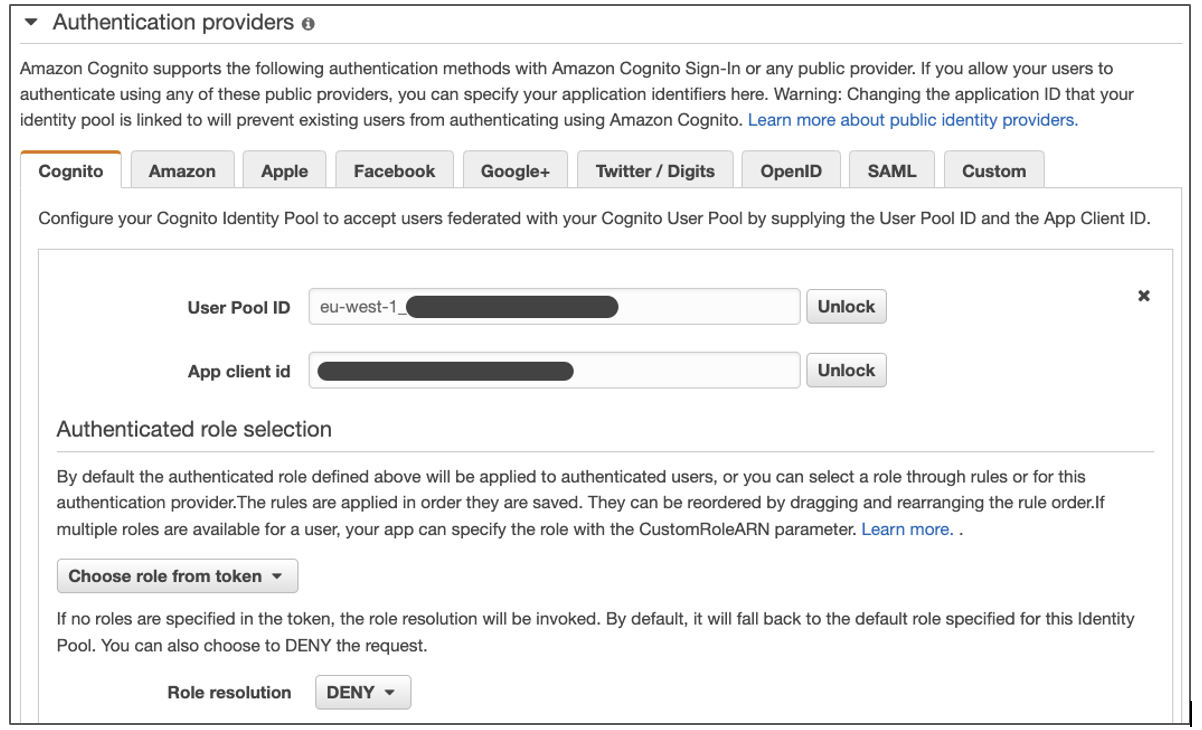
The Amazon Cognito identity pool configuration is set to Choose role from token for authenticated users, as in Figure 2. This setup permits authenticated users to pass the roles in the ID token that the Amazon Cognito user pool assigned. Backend Lambda functions use the roles that appear in the cognito:roles and cognito:preferred_role claims in the ID token for RBAC.

Amazon Cognito identity pool configuration – using tokens to assign roles to authenticated users

Figure 2. Amazon Cognito identity pool configuration – using tokens to assign roles to authenticated users

In the attributes for access control section, we configured a custom mapping from the augmented department token claim to a tag key, as in Figure 3. The backend logic uses the tag key to match the PrincipalTag condition in IAM policies to control access to AWS resources.

Amazon Cognito identity pool configuration – custom mapping from claim names to tag keys

Figure 3. Amazon Cognito identity pool configuration – custom mapping from claim names to tag keys

Document upload

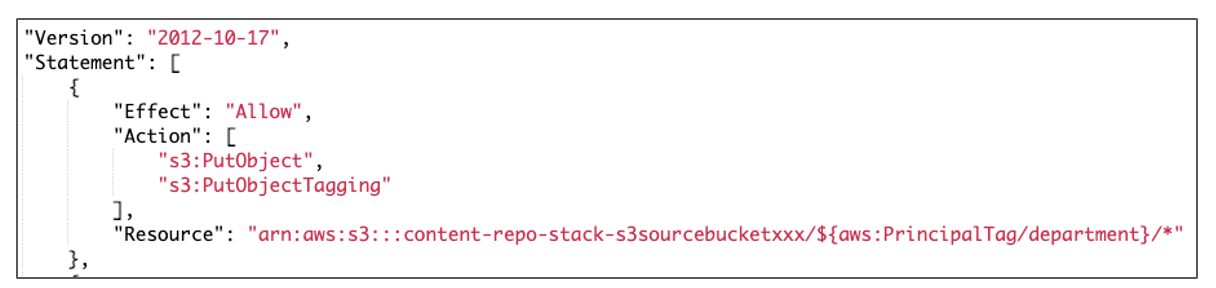
The presigned_url.py Lambda function generates a pre-signed Amazon S3 URL using the department token claim as the key. This function automatically organizes the uploaded document into a logical structure in the Amazon S3 source bucket. Accordingly, the cognito:preferred_role used for the Amazon S3 client credentials in the Lambda function has a permission policy using the PrincipalTag department to dynamically limit access to the Amazon S3 key, as in Figure 4.

Permission policy using PrincipalTag to upload documents to Amazon S3

Figure 4. Permission policy using PrincipalTag to upload documents to Amazon S3

Document listing

The list functionality only shows the uploaded content belonging to the preferred group of authenticated Amazon Cognito user pool user. To only list the files that a specific user (for example, sales-user) has access to, use the PrincipalTag s3:prefix condition, as in Figure 5.

Permission policy using s3:prefix condition with session tags to list documents

Figure 5. Permission policy using s3:prefix condition with session tags to list documents

Cleanup

In the backend-cdk subdirectory, delete the deployed resources:

cdk destroy --all

Conclusion

In this blog, we demonstrated how to build a content repository with an easy-to-use web application for unstructured data that ingests documents while maintaining dynamic access control for users within departments. These steps provide a foundation to build your own content repository to store and process documents. As next steps, based on your organization’s security requirements, you can implement more complex access control use cases by balancing IAM role and principal tags. For example, you can use Amazon Cognito user pool custom attributes for additional dimensions such as document “clearance” with optional modification in the pre-token generation Lambda.

In the next part of this blog series, we will enrich the content repository with multi-lingual semantic search features while maintaining the access control fundamentals we’ve already implemented. For additional information on how you can build a solution to search for information across multiple scanned documents, PDFs, and images with compliance capabilities, please refer our Document Understanding Solution from AWS Solutions Library.

Introducing AWS Lambda Powertools for .NET

Post Syndicated from Julian Wood original https://aws.amazon.com/blogs/compute/introducing-aws-lambda-powertools-for-net/

This blog post is written by Amir Khairalomoum, Senior Solutions Architect.

Modern applications are built with modular architectural patterns, serverless operational models, and agile developer processes. They allow you to innovate faster, reduce risk, accelerate time to market, and decrease your total cost of ownership (TCO). A microservices architecture comprises many distributed parts that can introduce complexity to application observability. Modern observability must respond to this complexity, the increased frequency of software deployments, and the short-lived nature of AWS Lambda execution environments.

The Serverless Applications Lens for the AWS Well-Architected Framework focuses on how to design, deploy, and architect your serverless application workloads in the AWS Cloud. AWS Lambda Powertools for .NET translates some of the best practices defined in the serverless lens into a suite of utilities. You can use these in your application to apply structured logging, distributed tracing, and monitoring of metrics.

Following the community’s continued adoption of AWS Lambda Powertools for Python, Java, and TypeScript, AWS Lambda Powertools for .NET is now generally available.

This post shows how to use the new open source Powertools library to implement observability best practices with minimal coding. It walks through getting started, with the provided examples available in the Powertools GitHub repository.

About Powertools

Powertools for .NET is a suite of utilities that helps with implementing observability best practices without needing to write additional custom code. It currently supports Lambda functions written in C#, with support for runtime versions .NET 6 and newer. Powertools provides three core utilities:

  • Tracing provides a simpler way to send traces from functions to AWS X-Ray. It provides visibility into function calls, interactions with other AWS services, or external HTTP requests. You can add attributes to traces to allow filtering based on key information. For example, when using the Tracing attribute, it creates a ColdStart annotation. You can easily group and analyze traces to understand the initialization process.
  • Logging provides a custom logger that outputs structured JSON. It allows you to pass in strings or more complex objects, and takes care of serializing the log output. The logger handles common use cases, such as logging the Lambda event payload, and capturing cold start information. This includes appending custom keys to the logger.
  • Metrics simplifies collecting custom metrics from your application, without the need to make synchronous requests to external systems. This functionality allows capturing metrics asynchronously using Amazon CloudWatch Embedded Metric Format (EMF) which reduces latency and cost. This provides convenient functionality for common cases, such as validating metrics against CloudWatch EMF specification and tracking cold starts.

Getting started

The following steps explain how to use Powertools to implement structured logging, add custom metrics, and enable tracing with AWS X-Ray. The example application consists of an Amazon API Gateway endpoint, a Lambda function, and an Amazon DynamoDB table. It uses the AWS Serverless Application Model (AWS SAM) to manage the deployment.

When you send a GET request to the API Gateway endpoint, the Lambda function is invoked. This function calls a location API to find the IP address, stores it in the DynamoDB table, and returns it with a greeting message to the client.

Example application

Example application

The AWS Lambda Powertools for .NET utilities are available as NuGet packages. Each core utility has a separate NuGet package. It allows you to add only the packages you need. This helps to make the Lambda package size smaller, which can improve the performance.

To implement each of these core utilities in a separate example, use the Globals sections of the AWS SAM template to configure Powertools environment variables and enable active tracing for all Lambda functions and Amazon API Gateway stages.

Sometimes resources that you declare in an AWS SAM template have common configurations. Instead of duplicating this information in every resource, you can declare them once in the Globals section and let your resources inherit them.

Logging

The following steps explain how to implement structured logging in an application. The logging example shows you how to use the logging feature.

To add the Powertools logging library to your project, install the packages from NuGet gallery, from Visual Studio editor, or by using following .NET CLI command:

dotnet add package AWS.Lambda.Powertools.Logging

Use environment variables in the Globals sections of the AWS SAM template to configure the logging library:

  Globals:
    Function:
      Environment:
        Variables:
          POWERTOOLS_SERVICE_NAME: powertools-dotnet-logging-sample
          POWERTOOLS_LOG_LEVEL: Debug
          POWERTOOLS_LOGGER_CASE: SnakeCase

Decorate the Lambda function handler method with the Logging attribute in the code. This enables the utility and allows you to use the Logger functionality to output structured logs by passing messages as a string. For example:

[Logging]
public async Task<APIGatewayProxyResponse> FunctionHandler
         (APIGatewayProxyRequest apigProxyEvent, ILambdaContext context)
{
  ...
  Logger.LogInformation("Getting ip address from external service");
  var location = await GetCallingIp();
  ...
}

Lambda sends the output to Amazon CloudWatch Logs as a JSON-formatted line.

{
  "cold_start": true,
  "xray_trace_id": "1-621b9125-0a3b544c0244dae940ab3405",
  "function_name": "powertools-dotnet-tracing-sampl-HelloWorldFunction-v0F2GJwy5r1V",
  "function_version": "$LATEST",
  "function_memory_size": 256,
  "function_arn": "arn:aws:lambda:eu-west-2:286043031651:function:powertools-dotnet-tracing-sample-HelloWorldFunction-v0F2GJwy5r1V",
  "function_request_id": "3ad9140b-b156-406e-b314-5ac414fecde1",
  "timestamp": "2022-02-27T14:56:39.2737371Z",
  "level": "Information",
  "service": "powertools-dotnet-sample",
  "name": "AWS.Lambda.Powertools.Logging.Logger",
  "message": "Getting ip address from external service"
}

Another common use case, especially when developing new Lambda functions, is to print a log of the event received by the handler. You can achieve this by enabling LogEvent on the Logging attribute. This is disabled by default to prevent potentially leaking sensitive event data into logs.

[Logging(LogEvent = true)]
public async Task<APIGatewayProxyResponse> FunctionHandler
         (APIGatewayProxyRequest apigProxyEvent, ILambdaContext context)
{
  ...
}

With logs available as structured JSON, you can perform searches on this structured data using CloudWatch Logs Insights. To search for all logs that were output during a Lambda cold start, and display the key fields in the output, run following query:

fields coldStart='true'
| fields @timestamp, function_name, function_version, xray_trace_id
| sort @timestamp desc
| limit 20
CloudWatch Logs Insights query for cold starts

CloudWatch Logs Insights query for cold starts

Tracing

Using the Tracing attribute, you can instruct the library to send traces and metadata from the Lambda function invocation to AWS X-Ray using the AWS X-Ray SDK for .NET. The tracing example shows you how to use the tracing feature.

When your application makes calls to AWS services, the SDK tracks downstream calls in subsegments. AWS services that support tracing, and resources that you access within those services, appear as downstream nodes on the service map in the X-Ray console.

You can instrument all of your AWS SDK for .NET clients by calling RegisterXRayForAllServices before you create them.

public class Function
{
  private static IDynamoDBContext _dynamoDbContext;
  public Function()
  {
    AWSSDKHandler.RegisterXRayForAllServices();
    ...
  }
  ...
}

To add the Powertools tracing library to your project, install the packages from NuGet gallery, from Visual Studio editor, or by using following .NET CLI command:

dotnet add package AWS.Lambda.Powertools.Tracing

Use environment variables in the Globals sections of the AWS SAM template to configure the tracing library.

  Globals:
    Function:
      Tracing: Active
      Environment:
        Variables:
          POWERTOOLS_SERVICE_NAME: powertools-dotnet-tracing-sample
          POWERTOOLS_TRACER_CAPTURE_RESPONSE: true
          POWERTOOLS_TRACER_CAPTURE_ERROR: true

Decorate the Lambda function handler method with the Tracing attribute to enable the utility. To provide more granular details for your traces, you can use the same attribute to capture the invocation of other functions outside of the handler. For example:

[Tracing]
public async Task<APIGatewayProxyResponse> FunctionHandler
         (APIGatewayProxyRequest apigProxyEvent, ILambdaContext context)
{
  ...
  var location = await GetCallingIp().ConfigureAwait(false);
  ...
}

[Tracing(SegmentName = "Location service")]
private static async Task<string?> GetCallingIp()
{
  ...
}

Once traffic is flowing, you see a generated service map in the AWS X-Ray console. Decorating the Lambda function handler method, or any other method in the chain with the Tracing attribute, provides an overview of all the traffic flowing through the application.

AWS X-Ray trace service view

AWS X-Ray trace service view

You can also view the individual traces that are generated, along with a waterfall view of the segments and subsegments that comprise your trace. This data can help you pinpoint the root cause of slow operations or errors within your application.

AWS X-Ray waterfall trace view

AWS X-Ray waterfall trace view

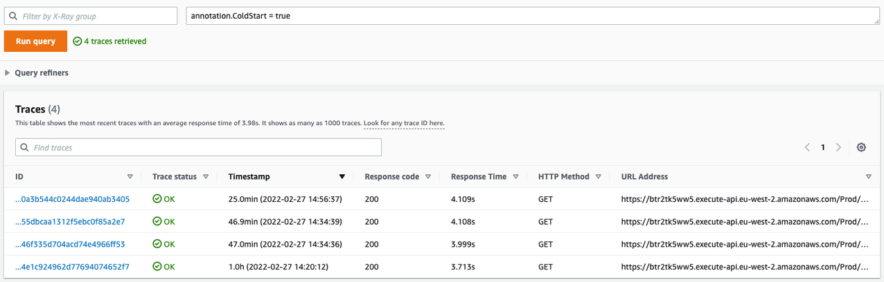
You can also filter traces by annotation and create custom service maps with AWS X-Ray Trace groups. In this example, use the filter expression annotation.ColdStart = true to filter traces based on the ColdStart annotation. The Tracing attribute adds these automatically when used within the handler method.

View trace attributes

View trace attributes

Metrics

CloudWatch offers a number of included metrics to help answer general questions about the application’s throughput, error rate, and resource utilization. However, to understand the behavior of the application better, you should also add custom metrics relevant to your workload.

The metrics utility creates custom metrics asynchronously by logging metrics to standard output using the Amazon CloudWatch Embedded Metric Format (EMF).

In the sample application, you want to understand how often your service is calling the location API to identify the IP addresses. The metrics example shows you how to use the metrics feature.

To add the Powertools metrics library to your project, install the packages from the NuGet gallery, from the Visual Studio editor, or by using the following .NET CLI command:

dotnet add package AWS.Lambda.Powertools.Metrics

Use environment variables in the Globals sections of the AWS SAM template to configure the metrics library:

  Globals:
    Function:
      Environment:
        Variables:
          POWERTOOLS_SERVICE_NAME: powertools-dotnet-metrics-sample
          POWERTOOLS_METRICS_NAMESPACE: AWSLambdaPowertools

To create custom metrics, decorate the Lambda function with the Metrics attribute. This ensures that all metrics are properly serialized and flushed to logs when the function finishes its invocation.

You can then emit custom metrics by calling AddMetric or push a single metric with a custom namespace, service and dimensions by calling PushSingleMetric. You can also enable the CaptureColdStart on the attribute to automatically create a cold start metric.

[Metrics(CaptureColdStart = true)]
public async Task<APIGatewayProxyResponse> FunctionHandler
         (APIGatewayProxyRequest apigProxyEvent, ILambdaContext context)
{
  ...
  // Add Metric to capture the amount of time
  Metrics.PushSingleMetric(
        metricName: "CallingIP",
        value: 1,
        unit: MetricUnit.Count,
        service: "lambda-powertools-metrics-example",
        defaultDimensions: new Dictionary<string, string>
        {
            { "Metric Type", "Single" }
        });
  ...
}

Conclusion

CloudWatch and AWS X-Ray offer functionality that provides comprehensive observability for your applications. Lambda Powertools .NET is now available in preview. The library helps implement observability when running Lambda functions based on .NET 6 while reducing the amount of custom code.

It simplifies implementing the observability best practices defined in the Serverless Applications Lens for the AWS Well-Architected Framework for a serverless application and allows you to focus more time on the business logic.

You can find the full documentation and the source code for Powertools in GitHub. We welcome contributions via pull request, and encourage you to create an issue if you have any feedback for the project. Happy building with AWS Lambda Powertools for .NET.

For more serverless learning resources, visit Serverless Land.

Implementing reactive progress tracking for AWS Step Functions

Post Syndicated from Benjamin Smith original https://aws.amazon.com/blogs/compute/implementing-reactive-progress-tracking-for-aws-step-functions/

This blog post is written by Alexey Paramonov, Solutions Architect, ISV and Maximilian Schellhorn, Solutions Architect ISV

This blog post demonstrates a solution based on AWS Step Functions and Amazon API Gateway WebSockets to track execution progress of a long running workflow. The solution updates the frontend regularly and users are able to track the progress and receive detailed status messages.

Websites with long-running processes often don’t provide feedback to users, leading to a poor customer experience. You might have experienced this when booking tickets, searching for hotels, or buying goods online. These sites often call multiple backend and third-party endpoints and aggregate the results to complete your request, causing the delay. In these long running scenarios, a transparent progress tracking solution can create a better user experience.

Overview

The example provided uses:

  • AWS Serverless Application Model (AWS SAM) for deployment: an open-source framework for building serverless applications.
  • AWS Step Functions for orchestrating the workflow.
  • AWS Lambda for mocking long running processes.
  • API Gateway to provide a WebSocket API for bidirectional communications between clients and the backend.
  • Amazon DynamoDB for storing connection IDs from the clients.

The example provides different options to report the progress back to the WebSocket connection by using Step Functions SDK integration, Lambda integrations, or Amazon EventBridge.

The following diagram outlines the example:

  1. The user opens a connection to WebSocket API. The OnConnect and OnDisconnect Lambda functions in the “WebSocket Connection Management” section persist this connection in DynamoDB (see documentation). The connection is bidirectional, meaning that the user can send requests through the open connection and the backend can respond with a new progress status whenever it is available.
  2. The user sends a new order through the WebSocket API. API Gateway routes the request to the “OnOrder” AWS Lambda function, which starts the state machine execution.
  3. As the request propagates through the state machine, we send progress updates back to the user via the WebSocket API using AWS SDK service integrations.
  4. For more customized status responses, we can use a centralized AWS Lambda function “ReportProgress” that updates the WebSocket API.

How to respond to the client?

To send the status updates back to the client via the WebSocket API, three options are explored:

Option 1: AWS SDK integration with API Gateway invocation

As the diagram shows, the API Gateway workflow tasks starting with the prefix “Report:” send responses directly to the client via the WebSocket API. This is an example of the state machine definition for this step:

          'Report: Workflow started':
            Type: Task
            Resource: arn:aws:states:::apigateway:invoke
            ResultPath: $.Params
            Parameters:
              ApiEndpoint: !Join [ '.',[ !Ref ProgressTrackingWebsocket, execute-api, !Ref 'AWS::Region', amazonaws.com ] ]
              Method: POST
              Stage: !Ref ApiStageName
              Path.$: States.Format('/@connections/{}', $.ConnectionId)
              RequestBody:
                Message: 🥁 Workflow started
                Progress: 10
              AuthType: IAM_ROLE
            Next: 'Mock: Inventory check'

This option reports the progress directly without using any additional Lambda functions. This limits the system complexity, reduces latency between the progress update and the response delivered to the client, and potentially reduces costs by reducing Lambda execution duration. A potential drawback is the limited customization of the response and getting familiar with the definition language.

Option 2: Using a Lambda function for reporting the progress status

To further customize response logic, create a Lambda function for reporting. As shown in point 4 of the diagram, you can also invoke a “ReportProgress” function directly from the state machine. This Python code snippet reports the progress status back to the WebSocket API:

apigw_management_api_client = boto3.client('apigatewaymanagementapi', endpoint_url=api_url)
apigw_management_api_client.post_to_connection(
            ConnectionId=connection_id,
            Data=bytes(json.dumps(event), 'utf-8')
        )

This option allows for more customizations and integration into the business logic of other Lambda functions to track progress in more detail. For example, execution of loops and reporting back on every iteration. The tradeoff is that you must handle exceptions and retries in your code. It also increases overall system complexity and additional costs associated with Lambda execution.

Option 3: Using EventBridge

You can combine option 2 with EventBridge to provide a centralized solution for reporting the progress status. The solution also handles retries with back-off if the “ReportProgress” function can’t communicate with the WebSocket API.

You can also use AWS SDK integrations from the state machine to EventBridge instead of using API Gateway. This has the additional benefit of a loosely coupled and resilient system but you could experience increased latency due to the additional services used. The combination of EventBridge and the Lambda function adds a minimal latency, but it might not be acceptable for short-lived workflows. However, if the workflow takes tens of seconds to complete and involves numerous steps, option 3 may be more suitable.

This is the architecture:

  1. As before.
  2. As before.
  3. AWS SDK integration sends the status message to EventBridge.
  4. The message propagates to the “ReportProgress” Lambda function.
  5. The Lambda function sends the processed message through the WebSocket API back to the client.

Deploying the example

Prerequisites

Make sure you can manage AWS resources from your terminal.

  • AWS CLI and AWS SAM CLI installed.
  • You have an AWS account. If not, visit this page.
  • Your user has sufficient permissions to manage AWS resources.
  • Git is installed.
  • NPM is installed (only for local frontend deployment).

To view the source code and documentation, visit the GitHub repo. This contains both the frontend and backend code.

To deploy:

  1. Clone the repository:
    git clone "https://github.com/aws-samples/aws-step-functions-progress-tracking.git"
  2. Navigate to the root of the repository.
  3. Build and deploy the AWS SAM template:
    sam build && sam deploy --guided
  4. Copy the value of WebSocketURL in the output for later.
  5. The backend is now running. To test it, use a hosted frontend.

Alternatively, you can deploy the React-based frontend on your local machine:

  1. Navigate to “progress-tracker-frontend/”:
    cd progress-tracker-frontend
  2. Launch the react app:
    npm start
  3. The command opens the React app in your default browser. If it does not happen automatically, navigate to http://localhost:3000/ manually.

Now the application is ready to test.

Testing the example application

  1. The webpage requests a WebSocket URL – this is the value from the AWS SAM template deployment. Paste it into Enter WebSocket URL in the browser and choose Connect.
  2. On the next page, choose Send Order and watch how the progress changes.

    This sends the new order request to the state machine. As it progresses, you receive status messages back through the WebSocket API.
  3. Optionally, you can inspect the raw messages arriving to the client. Open the Developer tools in your browser and navigate to the Network tab. Filter for WS (stands for WebSocket) and refresh the page. Specify the WebSocket URL, choose Connect and then choose Send Order.

Cleaning up

The services used in this solution are eligible for AWS Free Tier. To clean up the resources, in the root directory of the repository run:

sam delete

This removes all resources provisioned by the template.yml file.

Conclusion

In this post, you learn how to augment your Step Functions workflows with low latency progress tracking via API Gateway WebSockets. Consider adding the progress tracking to your long running workflows to improve the customer experience and provide a reactive look and feel for your application.

Navigate to the GitHub repository and review the implementation to see how your solution could become more user friendly and responsive. Start with examining the template.yml and the state machine’s definition and see how the frontend handles WebSocket communication and message visualization.

For more serverless learning resources, visit  Serverless Land.

Build a serverless analytics application with Amazon Redshift and Amazon API Gateway

Post Syndicated from David Zhang original https://aws.amazon.com/blogs/big-data/build-a-serverless-analytics-application-with-amazon-redshift-and-amazon-api-gateway/

Serverless applications are a modernized way to perform analytics among business departments and engineering teams. Business teams can gain meaningful insights by simplifying their reporting through web applications and distributing it to a broader audience.

Use cases can include the following:

  • Dashboarding – A webpage consisting of tables and charts where each component can offer insights to a specific business department.
  • Reporting and analysis – An application where you can trigger large analytical queries with dynamic inputs and then view or download the results.
  • Management systems – An application that provides a holistic view of the internal company resources and systems.
  • ETL workflows – A webpage where internal company individuals can trigger specific extract, transform, and load (ETL) workloads in a user-friendly environment with dynamic inputs.
  • Data abstraction – Decouple and refactor underlying data structure and infrastructure.
  • Ease of use – An application where you want to give a large set of user-controlled access to analytics without having to onboard each user to a technical platform. Query updates can be completed in an organized manner and maintenance has minimal overhead.

In this post, you will learn how to build a serverless analytics application using Amazon Redshift Data API and Amazon API Gateway WebSocket and REST APIs.

Amazon Redshift is fully managed by AWS, so you no longer need to worry about data warehouse management tasks such as hardware provisioning, software patching, setup, configuration, monitoring nodes and drives to recover from failures, or backups. The Data API simplifies access to Amazon Redshift because you don’t need to configure drivers and manage database connections. Instead, you can run SQL commands to an Amazon Redshift cluster by simply calling a secured API endpoint provided by the Data API. The Data API takes care of managing database connections and buffering data. The Data API is asynchronous, so you can retrieve your results later.

API Gateway is a fully managed service that makes it easy for developers to publish, maintain, monitor, and secure APIs at any scale. With API Gateway, you can create RESTful APIs and WebSocket APIs that enable real-time two-way communication applications. API Gateway supports containerized and serverless workloads, as well as web applications. API Gateway acts as a reverse proxy to many of the compute resources that AWS offers.

Event-driven model

Event-driven applications are increasingly popular among customers. Analytical reporting web applications can be implemented through an event-driven model. The applications run in response to events such as user actions and unpredictable query events. Decoupling the producer and consumer processes allows greater flexibility in application design and building decoupled processes. This design can be achieved with the Data API and API Gateway WebSocket and REST APIs.

Both REST API calls and WebSocket establish communication between the client and the backend. Due to the popularity of REST, you may wonder why WebSockets are present and how they contribute to an event-driven design.

What are WebSockets and why do we need them?

Unidirectional communication is customary when building analytical web solutions. In traditional environments, the client initiates a REST API call to run a query on the backend and either synchronously or asynchronously waits for the query to complete. The “wait” aspect is engineered to apply the concept of polling. Polling in this context is when the client doesn’t know when a backend process will complete. Therefore, the client will consistently make a request to the backend and check.

What is the problem with polling? Main challenges include the following:

  • Increased traffic in your network bandwidth – A large number of users performing empty checks will impact your backend resources and doesn’t scale well.
  • Cost usage – Empty requests don’t deliver any value to the business. You pay for the unnecessary cost of resources.
  • Delayed response – Polling is scheduled in time intervals. If the query is complete in-between these intervals, the user can only see the results after the next check. This delay impacts the user experience and, in some cases, may result in UI deadlocks.

For more information on polling, check out From Poll to Push: Transform APIs using Amazon API Gateway REST APIs and WebSockets.

WebSockets is another approach compared to REST when establishing communication between the front end and backend. WebSockets enable you to create a full duplex communication channel between the client and the server. In this bidirectional scenario, the client can make a request to the server and is notified when the process is complete. The connection remains open, with minimal network overhead, until the response is received.

You may wonder why REST is present, since you can transfer response data with WebSockets. A WebSocket is a light weight protocol designed for real-time messaging between systems. The protocol is not designed for handling large analytical query data and in API Gateway, each frame’s payload can only hold up to 32 KB. Therefore, the REST API performs large data retrieval.

By using the Data API and API Gateway, you can build decoupled event-driven web applications for your data analytical needs. You can create WebSocket APIs with API Gateway and establish a connection between the client and your backend services. You can then initiate requests to perform analytical queries with the Data API. Due to the Data API’s asynchronous nature, the query completion generates an event to notify the client through the WebSocket channel. The client can decide to either retrieve the query results through a REST API call or perform other follow-up actions. The event-driven architecture enables bidirectional interoperable messages and data while keeping your system components agnostic.

Solution overview

In this post, we show how to create a serverless event-driven web application by querying with the Data API in the backend, establishing a bidirectional communication channel between the user and the backend with the WebSocket feature in API Gateway, and retrieving the results using its REST API feature. Instead of designing an application with long-running API calls, you can use the Data API. The Data API allows you to run SQL queries asynchronously, removing the need to hold long, persistent database connections.

The web application is protected using Amazon Cognito, which is used to authenticate the users before they can utilize the web app and also authorize the REST API calls when made from the application.

Other relevant AWS services in this solution include AWS Lambda and Amazon EventBridge. Lambda is a serverless, event-driven compute resource that enables you to run code without provisioning or managing servers. EventBridge is a serverless event bus allowing you to build event-driven applications.

The solution creates a lightweight WebSocket connection between the browser and the backend. When a user submits a request using WebSockets to the backend, a query is submitted to the Data API. When the query is complete, the Data API sends an event notification to EventBridge. EventBridge signals the system that the data is available and notifies the client. Afterwards, a REST API call is performed to retrieve the query results for the client to view.

We have published this solution on the AWS Samples GitHub repository and will be referencing it during the rest of this post.

The following architecture diagram highlights the end-to-end solution, which you can provision automatically with AWS CloudFormation templates run as part of the shell script with some parameter variables.

The application performs the following steps (note the corresponding numbered steps in the process flow):

  1. A web application is provisioned on AWS Amplify; the user needs to sign up first by providing their email and a password to access the site.
  2. The user verifies their credentials using a pin sent to their email. This step is mandatory for the user to then log in to the application and continue access to the other features of the application.
  3. After the user is signed up and verified, they can sign in to the application and requests data through their web or mobile clients with input parameters. This initiates a WebSocket connection in API Gateway. (Flow 1, 2)
  4. The connection request is handled by a Lambda function, OnConnect, which initiates an asynchronous database query in Amazon Redshift using the Data API. The SQL query is taken from a SQL script in Amazon Simple Storage Service (Amazon S3) with dynamic input from the client. (Flow 3, 4, 6, 7)
  5. In addition, the OnConnect Lambda function stores the connection, statement identifier, and topic name in an Amazon DynamoDB database. The topic name is an extra parameter that can be used if users want to implement multiple reports on the same webpage. This allows the front end to map responses to the correct report. (Flow 3, 4, 5)
  6. The Data API runs the query, mentioned in step 2. When the operation is complete, an event notification is sent to EventBridge. (Flow 8)
  7. EventBridge activates an event rule to redirect that event to another Lambda function, SendMessage. (Flow 9)
  8. The SendMessage function notifies the client that the SQL query is complete via API Gateway. (Flow 10, 11, 12)
  9. After the notification is received, the client performs a REST API call (GET) to fetch the results. (Flow 13, 14, 15, 16)
  10. The GetResult function is triggered, which retrieves the SQL query result and returns it to the client.
  11. The user is now able to view the results on the webpage.
  12. When clients disconnect from their browser, API Gateway automatically deletes the connection information from the DynamoDB table using the onDisconnect function. (Flow 17, 18,19)

Prerequisites

Prior to deploying your event-driven web application, ensure you have the following:

  • An Amazon Redshift cluster in your AWS environment – This is your backend data warehousing solution to run your analytical queries. For instructions to create your Amazon Redshift cluster, refer to Getting started with Amazon Redshift.
  • An S3 bucket that you have access to – The S3 bucket will be your object storage solution where you can store your SQL scripts. To create your S3 bucket, refer to Create your first S3 bucket.

Deploy CloudFormation templates

The code associated to the design is available in the following GitHub repository. You can clone the repository inside an AWS Cloud9 environment in our AWS account. The AWS Cloud9 environment comes with AWS Command Line Interface (AWS CLI) installed, which is used to run the CloudFormation templates to set up the AWS infrastructure. Make sure that the jQuery library is installed; we use it to parse the JSON output during the run of the script.

The complete architecture is set up using three CloudFormation templates:

  • cognito-setup.yaml – Creates the Amazon Cognito user pool to web app client, which is used for authentication and protecting the REST API
  • backend-setup.yaml – Creates all the required Lambda functions and the WebSocket and Rest APIs, and configures them on API Gateway
  • webapp-setup.yaml – Creates the web application hosting using Amplify to connect and communicate with the WebSocket and Rest APIs.

These CloudFormation templates are run using the script.sh shell script, which takes care of all the dependencies as required.

A generic template is provided for you to customize your own DDL SQL scripts as well as your own query SQL scripts. We have created sample scripts for you to follow along.

  1. Download the sample DDL script and upload it to an existing S3 bucket.
  2. Change the IAM role value to your Amazon Redshift cluster’s IAM role with permissions to AmazonS3ReadOnlyAccess.

For this post, we copy the New York Taxi Data 2015 dataset from a public S3 bucket.

  1. Download the sample query script and upload it to an existing S3 bucket.
  2. Upload the modified sample DDL script and the sample query script into a preexisting S3 bucket that you own, and note down the S3 URI path.

If you want to run your own customized version, modify the DDL and query script to fit your scenario.

  1. Edit the script.sh file before you run it and set the values for the following parameters:
    • RedshiftClusterEndpoint (aws_redshift_cluster_ep) – Your Amazon Redshift cluster endpoint available on the AWS Management Console
    • DBUsername (aws_dbuser_name) – Your Amazon Redshift database user name
    • DDBTableName (aws_ddbtable_name) – The name of your DynamoDB table name that will be created
    • WebsocketEndpointSSMParameterName (aws_wsep_param_name) – The parameter name that stores the WebSocket endpoint in AWS Systems Manager Parameter Store.
    • RestApiEndpointSSMParameterName (aws_rapiep_param_name) – The parameter name that stores the REST API endpoint in Parameter Store.
    • DDLScriptS3Path (aws_ddl_script_path) – The S3 URI to the DDL script that you uploaded.
    • QueryScriptS3Path (aws_query_script_path) – The S3 URI to the query script that you uploaded.
    • AWSRegion (aws_region) – The Region where the AWS infrastructure is being set up.
    • CognitoPoolName (aws_user_pool_name) – The name you want to give to your Amazon Cognito user pool
    • ClientAppName (aws_client_app_name) – The name of the client app to be configured for the web app to handle the user authentication for the users

The default acceptable values are already provided as part of the downloaded code.

  1. Run the script using the following command:
./script.sh

During deployment, AWS CloudFormation creates and triggers the Lambda function SetupRedshiftLambdaFunction, which sets up an Amazon Redshift database table and populates data into the table. The following diagram illustrates this process.

Use the demo app

When the shell script is complete, you can start interacting with the demo web app:

  1. On the Amplify console, under All apps in the navigation pane, choose DemoApp.
  2. Choose Run build.

The DemoApp web application goes through a phase of Provision, Build, Deploy.

  1. When it’s complete, use the URL provided to access the web application.

The following screenshot shows the web application page. It has minimal functionality: you can sign in, sign up, or verify a user.

  1. Choose Sign Up.

  1. For Email ID, enter an email.
  2. For Password, enter a password that is at least eight characters long, has at least one uppercase and lowercase letter, at least one number, and at least one special character.
  3. Choose Let’s Enroll.

The Verify your Login to Demo App page opens.

  1. Enter your email and the verification code sent to the email you specified.
  2. Choose Verify.


You’re redirected to a login page.

  1. Sign in using your credentials.

You’re redirected to the demoPage.html website.

  1. Choose Open Connection.

You now have an active WebSocket connection between your browser and your backend AWS environment.

  1. For Trip Month, specify a month (for this example, December) and choose Submit.

You have now defined the month and year you want to query your data upon. After a few seconds, you can to see the output delivered from the WebSocket.

You may continue using the active WebSocket connection for additional queries—just choose a different month and choose Submit again.

  1. When you’re done, choose Close Connection to close the WebSocket connection.

For exploratory purposes, while your WebSocket connection is active, you can navigate to your DynamoDB table on the DynamoDB console to view the items that are currently stored. After the WebSocket connection is closed, the items stored in DynamoDB are deleted.

Clean up

To clean up your resources, complete the following steps:

  1. On the Amazon S3 console, navigate to the S3 bucket containing the sample DDL script and query script and delete them from the bucket.
  2. On the Amazon Redshift console, navigate to your Amazon Redshift cluster and delete the data you copied over from the sample DDL script.
    1. Run truncate nyc_yellow_taxi;
    2. Run drop table nyc_yellow_taxi;
  3. On the AWS CloudFormation console, navigate to the CloudFormation stacks and choose Delete. Delete the stacks in the following order:
    1. WebappSetup
    2. BackendSetup
    3. CognitoSetup

All resources created in this solution will be deleted.

Monitoring

You can monitor your event-driven web application events, user activity, and API usage with Amazon CloudWatch and AWS CloudTrail. Most areas of this solution already have logging enabled. To view your API Gateway logs, you can turn on CloudWatch Logs. Lambda comes with default logging and monitoring and can be accessed with CloudWatch.

Security

You can secure access to the application using Amazon Cognito, which is a developer-centric and cost-effective customer authentication, authorization, and user management solution. It provides both identity store and federation options that can scale easily. Amazon Cognito supports logins with social identity providers and SAML or OIDC-based identity providers, and supports various compliance standards. It operates on open identity standards (OAuth2.0, SAML 2.0, and OpenID Connect). You can also integrate it with API Gateway to authenticate and authorize the REST API calls either using the Amazon Cognito client app or a Lambda function.

Considerations

The nature of this application includes a front-end client initializing SQL queries to Amazon Redshift. An important component to consider are potential malicious activities that the client can perform, such as SQL injections. With the current implementation, that is not possible. In this solution, the SQL queries preexist in your AWS environment and are DQL statements (they don’t alter the data or structure). However, as you develop this application to fit your business, you should evaluate these areas of risk.

AWS offers a variety of security services to help you secure your workloads and applications in the cloud, including AWS Shield, AWS Network Firewall, AWS Web Application Firewall, and more. For more information and a full list, refer to Security, Identity, and Compliance on AWS.

Cost optimization

The AWS services that the CloudFormation templates provision in this solution are all serverless. In terms of cost optimization, you only pay for what you use. This model also allows you to scale without manual intervention. Review the following pages to determine the associated pricing for each service:

Conclusion

In this post, we showed you how to create an event-driven application using the Amazon Redshift Data API and API Gateway WebSocket and REST APIs. The solution helps you build data analytical web applications in an event-driven architecture, decouple your application, optimize long-running database queries processes, and avoid unnecessary polling requests between the client and the backend.

You also used severless technologies, API Gateway, Lambda, DynamoDB, and EventBridge. You didn’t have to manage or provision any servers throughout this process.

This event-driven, serverless architecture offers greater extensibility and simplicity, making it easier to maintain and release new features. Adding new components or third-party products is also simplified.

With the instructions in this post and the generic CloudFormation templates we provided, you can customize your own event-driven application tailored to your business. For feedback or contributions, we welcome you to contact us through the AWS Samples GitHub Repository by creating an issue.


About the Authors

David Zhang is an AWS Data Architect in Global Financial Services. He specializes in designing and implementing serverless analytics infrastructure, data management, ETL, and big data systems. He helps customers modernize their data platforms on AWS. David is also an active speaker and contributor to AWS conferences, technical content, and open-source initiatives. During his free time, he enjoys playing volleyball, tennis, and weightlifting. Feel free to connect with him on LinkedIn.

Manash Deb is a Software Development Manager in the AWS Directory Service team. With over 18 years of software dev experience, his passion is designing and delivering highly scalable, secure, zero-maintenance applications in the AWS identity and data analytics space. He loves mentoring and coaching others and to act as a catalyst and force multiplier, leading highly motivated engineering teams, and building large-scale distributed systems.

Pavan Kumar Vadupu Lakshman Manikya is an AWS Solutions Architect who helps customers design robust, scalable solutions across multiple industries. With a background in enterprise architecture and software development, Pavan has contributed in creating solutions to handle API security, API management, microservices, and geospatial information system use cases for his customers. He is passionate about learning new technologies and solving, automating, and simplifying customer problems using these solutions.
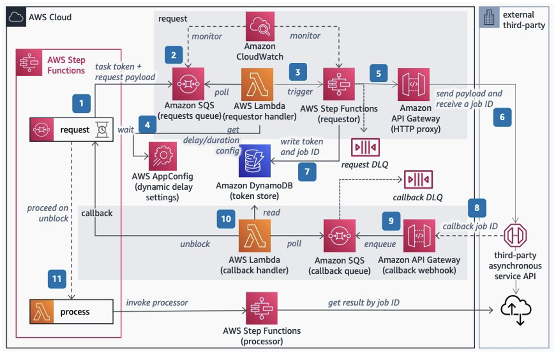
Best practices for working with the Apache Velocity Template Language in Amazon API Gateway

Post Syndicated from Benjamin Smith original https://aws.amazon.com/blogs/compute/best-practices-for-working-with-the-apache-velocity-template-language-in-amazon-api-gateway/

This post is written by Ben Freiberg, Senior Solutions Architect, and Marcus Ziller, Senior Solutions Architect.

One of the most common serverless patterns are APIs built with Amazon API Gateway and AWS Lambda. This approach is supported by many different frameworks across many languages. However, direct integration with AWS can enable customers to increase the cost-efficiency and resiliency of their serverless architecture. This blog post discusses best practices for using Apache Velocity Templates for direct service integration in API Gateway.

Deciding between integration via Velocity templates and Lambda functions

Many use cases of Velocity templates in API Gateway can also be solved with Lambda. With Lambda, the complexity of integrating with different backends is moved from the Velocity templating language (VTL) to the programming language. This allows customers to use existing frameworks and methodologies from the ecosystem of their preferred programming language.

However, many customers choose serverless on AWS to build lean architectures and using additional services such as Lambda functions can add complexity to your application. There are different considerations that customers can use to assess the trade-offs between the two approaches.

Developer experience

Apache Velocity has a number of operators that can be used when an expression is evaluated, most prominently in #if and #set directives. These operators allow you to implement complex transformations and business logic in your Velocity templates.

However, this adds complexity to multiple aspects of the development workflow:

  • Testing: Testing Velocity templates is possible but the tools and methodologies are less mature than for traditional programming languages used in Lambda functions.
  • Libraries: API Gateway offers utility functions for VTL that simplify common use cases such as data transformation. Other functionality commonly offered by programming language libraries (for example, Python Standard Library) might not be available in your template.
  • Logging: It is not possible to log information to Amazon CloudWatch from a Velocity template, so there is no option to retain this information.
  • Tracing: API Gateway supports request tracing via AWS X-Ray for native integrations with services such as Amazon DynamoDB.

You should use VTL for data mapping and transformations rather than complex business logic. There are exceptions but the drawbacks of using VTL for other use cases often outweigh the benefits.

API lifecycle

The API lifecycle is an important aspect to consider when deciding on Velocity or Lambda. In early stages, requirements are typically not well defined and can change rapidly while exploring the solution space. This often happens when integrating with databases such as Amazon DynamoDB and finding out the best way to organize data on the persistence layer.

For DynamoDB, this often means changes to attributes, data types, or primary keys. In such cases, it is a sensible decision to start with Lambda. Writing code in a programming language can give developers more leeway and flexibility when incorporating changes. This shortens the feedback loop for changes and can improve the developer experience.

When an API matures and is run in production, changes typically become less frequent and stability increases. At this point, it can make sense to evaluate if the Lambda function can be replaced by moving logic into Velocity templates. Especially for busy APIs, the one-time effort of moving Lambda logic to Velocity templates can pay off in the long run as it removes the cost of Lambda invocations.

Latency

In web applications, a major factor of user perceived performance is the time it takes for a page to load. In modern single page applications, this often means multiple requests to backend APIs. API Gateway offers features to minimize the latency for calls on the API layer. With Lambda for service integration, an additional component is added into the execution flow of the request, which inevitably introduces additional latency.

The degree of that additional latency depends on the specifics of the workload, and often is as low as a few milliseconds.

The following example measures no meaningful difference in latency other than cold starts of the execution environments for a basic CRUD API with a Node.js Lambda function that queries DynamoDB. I observe similar results for Go and Python.

Concurrency and scalability

Concurrency and scalability of an API changes when having an additional Lambda function in the execution path of the request. This is due to different Service Quotas and general scaling behaviors in different services.

For API Gateway, the current default quota is 10,000 requests per second (RPS) with an additional burst capacity provided by the token bucket algorithm, using a maximum bucket capacity of 5,000 requests. API Gateway quotas are independent of Region, while Lambda default concurrency limits depend on the Region.

After the initial burst, your functions’ concurrency can scale by an additional 500 instances each minute. This continues until there are enough instances to serve all requests, or until a concurrency limit is reached. For more details on this topic, refer to Understanding AWS Lambda scaling and throughput.

If your workload experiences sharp spikes of traffic, a direct integration with your persistence layer can lead to a better ability to handle such spikes without throttling user requests. Especially for Regions with an initial burst capacity of 1000 or 500, this can help avoid throttling and provide a more consistent user experience.

Best practices

Organize your project for tooling support

When VTL is used in Infrastructure as Code (IaC) artifacts such as AWS CloudFormation templates, it must be embedded into the IaC document as a string.

This approach has three main disadvantages:

  • Especially with multi-line Velocity templates, this leads to IaC definitions that are difficult to read or write.
  • Tools such as IDEs or Linters do not work with string representations of Velocity templates.
  • The templates cannot be easily used outside of the IaC definition, such as for local testing.

Each aspect impacts developer productivity and make the implementation more prone to errors.

You should decouple the definition of Velocity templates from the definition of IaC templates wherever possible. For the CDK, the implementation requires only a few lines of code.

// The following code is licensed under MIT-0 
import { readFileSync } from 'fs';
import * as path from 'path';

const getUserIntegrationWithVTL = new AwsIntegration({
      service: 'dynamodb',
      integrationHttpMethod: HttpMethods.POST,
      action: 'GetItem',
      options: {
        // Omitted for brevity
        requestTemplates: {
          'application/json': readFileSync(path.join('path', 'to', 'vtl', 'request.vm'), 'utf8').toString(),
        },
        integrationResponses: [
          {
            statusCode: '200',
            responseParameters: {
              'method.response.header.access-control-allow-origin': "'*'",
            },
            responseTemplates: {
              'application/json': readFileSync(path.join('path', 'to', 'vtl', 'request.vm'), 'utf8').toString(),
            },
          },
        ],
      },
    });

Another advantage of this approach is that it forces you to externalize variables in your templates. When defining Velocity templates inside of IaC documents, it is possible to refer to other resources in the same IaC document and set this value in the Velocity template through string concatenation. However, this hardcodes the value into the template as opposed to the recommended way of using Stage Variables.

Test Velocity templates locally

A frequent challenge that customers face with Velocity templates is how to shorten the feedback loop when implementing a template. A common workflow to test changes to templates is:

  1. Make changes to the template.
  2. Deploy the stack.
  3. Test the API endpoint.
  4. Evaluate the results or check logs for errors.
  5. Complete or return to step 1.

Depending on the duration of the stack deployment, this can often lead to feedback loops of several minutes. Although the test ecosystem for Velocity is far from being as extensive as it is for mainstream programming languages, there are still ways to improve the developer experience when writing VTL.

Local Velocity rendering engine with AWS SDK

When API Gateway receives a request that has an AWS integration target, the following things happen:

  1. Retrieve request context: API Gateway retrieves request parameters and stage variables.
  2. Make request: body:  API Gateway uses the template and variables from 1 to render a JSON document.
  3. Send request: API Gateway makes an API call to the respective AWS Service. It abstracts Authorization (via it’s IAM Role), Encoding and other aspects of the request away so that only the request body needs to be provided by API Gateway
  4. Retrieve response: API Gateway retrieves a JSON response from the API call.
  5. Make response body: If the call was successful the JSON response is used as input to render the response template. The result will then be sent back to the client that initiated the request to the API Gateway

To simplify our developing workflow, you can locally replicate the above flow with the AWS SDK and a Velocity rendering engine of your choice.

I recommend using Node.js for two reasons:

  • The velocityjs library is a lightweight but powerful Velocity render engine
  • The client methods (e.g. dynamoDbClient.query(jsonBody)) of the AWS SDK for JavaScript generally expect the same JSON body like the AWS REST API does. For most use cases, no transformation (e.g. camel case to Pascal case) is thus needed

The following snippet shows how to test Velocity templates for request and response of a DynamoDB Service Integration. It loads templates from files and renders them with context and parameters. Refer to the git repository for more details.

// The following code is licensed under MIT-0 
const fs = require('fs')
const Velocity = require('velocityjs');
const AWS = require('@aws-sdk/client-dynamodb');
const ddb = new AWS.DynamoDB()

const requestTemplate = fs.readFileSync('path/to/vtl/request.vm', 'utf8')
const responseTemplate = fs.readFileSync(''path/to/vtl/response.vm', 'utf8')

async function testDynamoDbIntegration() {
  const requestTemplateAsString = Velocity.render(requestTemplate, {
    // Mocks the variables provided by API Gateway
    context: {
      arguments: {
        tableName: 'MyTable'
      }
    },
    input: {
      params: function() {
        return 'someId123'
      },
    },
  });

  print(requestTemplateAsString)

  const sdkJsonRequestBody = JSON.parse(requestTemplateAsString)
  const item = await ddb.query(sdkJsonRequestBody)

  const response = Velocity.render(responseTemplate, {
    input: {
      path: function() {
        return {
          Items: item.Items
        }
      },
    },
  })

  const jsonResponse = JSON.parse(response)
}

This approach does not cover all use cases and ultimately must be validated by a deployment of the template. However, it helps to reduce the length of one feedback loop from minutes to a few seconds and allows for faster iterations in the development of Velocity templates.

Conclusion

This blog post discusses considerations and best practices for working with Velocity Templates in API Gateway. Developer experience, latency, API lifecycle, cost, and scalability are key factors when choosing between Lambda and VTL. For most use cases, we recommend Lambda as a starting point and VTL as an optimization step.

Setting up a local test environment for VTL helps shorten the feedback loop significantly and increase developer productivity. The AWS CDK is the recommended IaC framework for working with VTL projects, since it enables you to efficiently organize your infrastructure as code project for tooling support.

For more serverless learning resources, visit Serverless Land.

Running Next.js applications with serverless services on AWS

Post Syndicated from James Beswick original https://aws.amazon.com/blogs/compute/running-next-js-applications-with-serverless-services-on-aws/

This is written by Julian Bonilla, Senior Solutions Architect, and Matthew de Anda, Startup Solutions Architect.

React is a popular JavaScript library used to create single-page applications (SPAs). React focuses on helping to build UIs, but leaves it up to developers to decide how to accomplish other aspects involved with developing a SPA.

Next.js is a React framework to help provide more structure and solve common application requirements such as routing and data fetching. Next.js also provides multiple types of rendering methods – Static Site Generation (SSG), Server-Side Rendering (SSR), Incremental Static Regeneration (ISR), and Client-Side Rendering (CSR).

This post demonstrates how to build a Next.js application with Serverless services on AWS and explains Next.js Server-Side rendering. To deploy this solution and to provision the AWS resources, you can use either AWS Serverless Application Model (AWS SAM) or AWS Cloud Development Kit (CDK). Both are open-source frameworks to automate AWS deployment. AWS SAM is a declarative framework for building serverless applications and CDK is an imperative framework to define cloud application resources using familiar programming languages.

Overview

To render a Next.js application, you use Amazon S3, Amazon CloudFront, Amazon API Gateway, and AWS Lambda. Static resources are hosted in a private S3 bucket with a CloudFront distribution. Since static sources are generated at build time, this takes advantage of CloudFront so browsers can load these files cached on the network edge instead of from the server.

The Next.js application components that uses server-side rendering is rendered with a Lambda function using AWS Lambda Web Adapter. The CloudFront distribution is configured to forward requests to the API Gateway endpoint, which then calls the Lambda function.

  1. Static files (for example, CSS, JavaScript, and HTML) are mapped to /_next/static/* and /public/*.
  2. Server-side rendering is mapped with default behavior (*).
  3. The AWS Lambda Adapter runs Next.js Output File Tracing.

What’s Next.js?

Next.js is a React framework that creates a more opinionated approach to building web applications while providing additional structure and features such as Server-Side Rendering and Static Site Generation.

These additional rendering options provide more flexibility over the typical ways a React application is built, which is to render in the client’s browser with JavaScript. This can help in scenarios where customers have JavaScript disabled and can improve search engine optimization (SEO). While you can implement SSR in React applications, Next.js makes it simpler for developers.

Next.js rendering strategies

These are the different rendering strategies offered by Next.js:

  • Static Site Generation generates static resources at build time and is a good rendering strategy for static content that rarely changes and SEO.
  • Server-Side Rendering generates each page on-demand at request time and is good for pages that are dynamic. Since from the browser perspective it’s still pre-rendered, like Static Site Generation, it’s also good for SEO.
  •  Incremental Static Regeneration is a new rendering strategy that is good for apps with many pages where build times are high. With Incremental Static Regeneration, you can build page per-page without needing to rebuild the entire app.
  • Client-Side Rendering is the typical rendering strategy where the application is rendered in the browser with JavaScript. Next.js lets you choose the appropriate rendering method page-by-page. When a Next.js application is built, Next.js transforms the application to production-optimized files. You have HTML for statically generated pages, JavaScript for rendering on the server, JavaScript for rendering on the client, and CSS files.

Next.js also supports static HTML export, which has no server side component. Features that require a server are not supported with this approach. These apps can be hosted from S3 and CloudFront.

The remainder of this post focuses on Static Site Generation and Server-Side Rendering.

Next.js application project structure

Understanding how Next.js structures projects can give insight into how you deploy the application. A page is a React Component exported from files in the “pages” directory. These files are also used for routing where pages/index.js is routed to / route.

By default, these pages are pre-rendered. Static assets, such as images, are stored under “public” directory and can be referenced from /. Since these files are best stored in persistent storage and backed by a content delivery network (CDN), you can add a prefix in the implementation to distinguish these static files.

To create dynamic routes, add brackets to a page file – for example, pages/user/[id].js. This creates a statically generated page with the path /user/<id> where <id> can be dynamic.

API routes provide a way to create an API endpoint and are located in the pages/api directory. When building, Next.js generates an optimized version of your application under the .next directory. Static files not stored in the public directory are in .next/static. These static files are expected to be uploaded as _next/static to a CDN.

No other code in the .next/directory should be uploaded to a CDN because that would expose server code and other configuration.

Implementation

Next.js pre-renders HTML for every page using Static Site Generation or Server-side Rendering. For Static Site Generation, pages are rendered at build time and can be cached in CloudFront. Server-side rendered pages are rendered at request time, and typically fetch data from downstream resources on each request.

Clients connect to a CloudFront distribution, which is configured to forward requests for static resources to S3 and all other requests to API Gateway. API Gateway forwards requests to the Next.js application running on Lambda, which performs the server-side rendering.

At build time, Next.js Output File Tracing determines the minimal set of files needed for deploying to Lambda. The files are automatically copied to a standalone directory and must be enabled in next.config.js.

const nextConfig = {
  reactStrictMode: true,
  output: 'standalone',
}
module.exports = nextConfig

Since the Next.js application is essentially a webserver, this example uses the AWS Lambda Web Adapter as a Lambda layer to convert incoming events from API Gateway to HTTP requests that Next.js can process.

Once processed, the AWS Lambda Web Adapter converts the HTTP response back to a Lambda event response. The Lambda handler is configured to run the minimal server.js file created by the standalone build step.

The CloudFront distribution has two origins: one for the S3 bucket and another for the API Gateway. Two behaviors are created to specify path patterns to route static content produced by Next.js and static resources stored under the public/static directory. Next.js uses the public directory under root to serve static assets such as images.

These assets are then served under / so if you add public/me.png, it would be served at /me.png. This makes it harder to create a CloudFront behavior for these assets. One workaround is to create a static directory under the public directory and then map it to the CloudFront behavior. The default(*) path pattern behavior has the origin set to API Gateway with caching disabled.

Prerequisites and deployment

Refer to the project in its GitHub repository for instructions to deploy the solution using AWS SAM or AWS CDK. Multiple resources are provisioned for you as part of the deployment, and it takes several minutes to complete. The example Next.js application deployed is created using Create Next App.

Understanding the Next.js Application

To create a new page, you create a file under the pages directory and that creates a route based on the name (e.g. pages/hello.js creates route /hello). To create dynamic routes, create a file following the project’s example of pages/posts/[id].js to produce routes for posts/1, posts/2, and so forth.

For API routes, any file added to the directory pages/api is mapped to /api/* and becomes an API endpoint. These are server-side only bundles hosted by API Gateway and Lambda.

Conclusion

This blog shows how to run Next.js applications using S3, CloudFront, API Gateway, and Lambda. This architecture supports building Next.js applications that can use static-site generation, server-side rendering, and client-side rendering. The blog also covers how you can use open-source frameworks, AWS SAM and CDK, to build and deploy your Next.js applications.

If your organization is looking for a fully managed hosting of your Next.js applications, AWS Amplify Hosting supports Next.js. If interested in learning more about server-side rendering and micro-frontends, see Server-side rendering micro-frontends – the architecture.

For more serverless learning resources, visit Serverless Land.

Organize your AWS Serverless code to prevent merge conflicts

Post Syndicated from Mark Curtis original https://aws.amazon.com/blogs/devops/organize-your-aws-serverless-code-to-prevent-merge-conflicts/

How do you prevent the most common merge conflicts when your team is working on a Serverless application? How do you make sure that your team stays productive and avoids large merge issues while trying to update the same crucial files simultaneously? –The answer to both questions is code organization! You can use cfn-include and swagger-cli to organize, collaborate, and maintain a large serverless application as well as support a large or decentralized development team.

Real life inspiration

WRAP Technologies Inc. (WRAP) creates advanced technologies for the protection and security of public safety. Their WRAP Reality product allows law enforcement agencies to train their officers using virtual reality-based scenarios.

Too many cooks in the kitchen

When multiple developers collaborate on a serverless architecture built with AWS CloudFormation, and its extensions such as the AWS Serverless Application Model (SAM), the nature of specifying resources in both the template.yaml and the optional OpenAPI.yaml specification for Amazon API Gateway leads to merge conflicts, such as the one demonstrated in the following figure  where two developers are adding different API endpoints at the same time. These conflicts detract from the developer’s time and agility. Furthermore, navigating and maintaining the long template files required for a larger serverless architecture slows development  as the developer scans large files to find a particular resource definition.

Figure 1. The frustrating merge conflicts.

Figure 1. The frustrating merge conflicts.

By refactoring and organizing the CloudFormation and OpenAPI files, your development team can realize several benefits:

  • Improve developer efficiency by decomposing large, hard-to-manage files into a series of well-organized and single-purpose files.
  • Enhance developer productivity by allowing each developer to have ownership of their own code, thereby reducing the need to coordinate merges with teammates.
  • Eliminate potential merge issues for files that generate the most conflicts during the development of a typical Serverless API application.

Rapid development

WRAP partnered with AWS to develop and host the backend for their new officer training management platform. This entirely new platform was developed, completed, and available for use in a matter of months. Moreover, it’s a collaboration of developers spread across multiple teams worldwide, all contributing to the same code base. By instituting the norms and techniques of this post, WRAP created a large and maintainable serverless application with minimal developer code collisions.

Development of the WRAP Reality training management system was accomplished using CloudFormation for defining Infrastructure as Code (IaC), and an Amazon API Gateway OpenAPI specification for defining API contracts. The development team for the WRAP Reality training management service leveraged agile development for expediency, including the GitHub Flow branching strategy. However, since project contributors were not co-located, several considerations were put in place to make sure of consistency and speed of code development:

  • The API specifications and contracts were defined in OpenAPI (Swagger) specifications early in the development process, clearly defining the project structure up front, and allowing developers to independently build infrastructure components.
  • The two code assets central to the entire project – the CloudFormation template and the OpenAPI Specification – were decomposed into small, easily manageable components. This enabled components to be organized in a way that enhanced development productivity and practically eliminated the inevitable merge conflicts that come with large source code files that are being modified on a daily basis.

The development process was accelerated by utilizing OpenAPI integrations with AWS Services, as well as techniques for managing the OpenAPI specification and Cloudformation Template files.

Sample project

To demonstrate these techniques, we’ll explore the following sample project comprised of API endpoints for “widget” management, available on GitHub. This project provides the following end points:

  • /widget PUT: Creation of a new widget
  • /widget GET: Retrieval of a new widget
  • /reports/color GET: Retrieval of a set of widgets based on the widget color
  • /reports/filterpage GET: Retrieval of widgets based on specified filters

The overall architecture of the application is shown in the following diagram:

Figure 2. Architecture Diagram

Figure 2. Architecture Diagram

The application comprises:

  • Amazon API Gateway is a fully-managed service that makes it easy for developers to create, publish, maintain, monitor, and secure APIs at any scale. In this example, API Gateway serves as the web service for the API endpoints. The mapping of data to and from the API endpoints to the Lambda functions is formally defined by an OpenAPI specification file.
  • AWS Lambda is a serverless compute service that lets you run code without provisioning or managing servers, creating workload-aware cluster scaling logic, maintaining event integrations, or managing runtimes. In this example, four Lambda functions are used to service each of the four API calls.
  • Amazon DynamoDB is a key-value and document database that delivers single-digit millisecond performance at any scale. DynamoDB is used as a persistent data store for widgets and associated properties.

OpenAPI and AWS service integration

When using API Gateway, developers have the option of using proxy Lambda integrations, or formally defining the API interface in an OpenAPI yaml file. The OpenAPI specification can be leveraged to document the API prior to development, and the example/mock features of the OpenAPI specification facilitates concurrent development by quickly establishing a working infrastructure to build upon. Furthermore, API documentation can be automatically generated from the OpenAPI specification.

As the number of endpoints increases, the OpenAPI specification file can grow in size, reaching thousands of lines of code that must be updated and maintained regularly by multiple developers. To aid in management and usability, the OpenAPI file can be decomposed into separate files for endpoints, responses, fields, and schemas.

Start with a “skeleton” file as an entry point for the OpenAPI definition, and then add a separate file for the definition of each endpoint or construct. For example, the sample project entry point is api/apiSkeleton.yaml, which contains the global definitions and effectively defines a simple list of endpoints and the reference ($ref) file path to each endpoint’s definition.

The application comprises:

/reports/color:
    $ref: './paths/reports/reportsColor.yaml'

  /reports/filterpage:
    $ref: './paths/reports/reportsFilterPage.yaml'

Diving into a file referenced by an endpoint, we see that it contains all of the specification details for that endpoint. Looking at the reportsColor.yaml file reveals the full endpoint specification for /reports/color:

get:
  description: Get widgets by color
  parameters:
    - in: path
      $ref: '../../requestParameters/color.yaml'
  responses:
    200:
      description: Get All the Widgets of a color
      content:
        application/json:
          schema:
            $ref: '../../schemas/widgetList.yaml'
    . . .

In turn, this endpoint specification can include further references to yaml files defining common parameters, schemas, and even full gateway responses. For example, color.yaml defines the color path variable:

  type: string
    description: "The widget's color"
    example: "Red"

To paraphrase a common catch phrase, “With a great many files, comes a great responsibility for organization.” To this end, we offer the following organizational structure as a start. Place all of the related API specifications in an “api” subfolder of your project. Have child subfolders for field, metadata, and gateway response definition files. Then, create child subfolder trees for each branch of your endpoints that mirror the endpoint paths. This will result in a highly-organized directory structure, as seen in the sample project:

├── api
│   ├── apiSkeleton.yaml
│   ├── fields
│   │   ├── color.yaml
│   │   ├── metadata
│   │   │   ├── count.yaml
│   │   │   ├── message.yaml
│   │   └── widgetname.yaml
│   ├── gatewayResponses
│   │   ├── error.yaml
│   │   └── notFound.yaml
│   ├── paths
│   │   ├── reports
│   │   │   ├── reportsColor.yaml
│   │   │   └── reportsFilterPage.yaml
│   │   └── widget
│   │       ├── widgetPut.yaml
│   │       └── widgetWidgetnameGet.yaml

We still need a consolidated single OpenAPI file to provide to CloudFormation during deployment to AWS. Therefore, the multiple files are combined and validated using the swagger-cli bundle command, resulting in a single file for deployment. The bundle command must be executed before a CloudFormation build. This command can also be included as a shortcut in the Makefile as the “buildOpenApi” command:

swagger-cli bundle -o api/api.yaml --dereference --t yaml  api/apiSkeleton.yaml

or

make buildOpenApi

Once compiled, api/api.yaml is then used normally for API Gateway integrations and as a Postman  API Collection import. As api/api.yaml is dynamically compiled, it’s included in .gitignore and not checked in to AWS CodeCommit.

cfn-include and nested stacks

The CloudFormation template that defines the infrastructure for even a simple service can grow to considerable length, perhaps thousands of lines. This presents challenges from a support and continued development perspective, as specific code locations become difficult to find and merge conflicts become commonplace.

CloudFormation Nested Stacks are a method of breaking a large CloudFormation template into separate templates. When there are clear delineations between groups of resources in a stack breaking it into separate nested stacks makes sense. There is also a 500 resource limit in a single CloudFormation stack and in order to go above that nested or separate stacks are necessary. Depending on the complexity of the architecture and frequency of updates however, the Nested Stacks can also become large. Furthermore, in a serverless architecture, the logical separation of architecture layers into separate stacks may not be direct, for example when a Lambda function is triggered by an event sent to an EventBridge event bus, then that Lambda function sends a different event back to the same event bus.

In these cases, CloudFormation templates can be decomposed to further leverage cfn-include . With this technique, the top-level CloudFormation template becomes a skeleton file which contains the stack parameters, global specifications, a list of resource names without properties, and the outputs. The properties of each resource are contained in separate files, referenced by an ‘include’ directive.
CloudFormation template organization

To organize your CloudFormation template, deconstruct the template into one-file-per-resource, with one main “skeleton” file as the main entry point. This skeleton file contains the full parameters, global section, conditions, and output specification. The resources are specified by resource name in this skeleton file, and then an ‘include’ directive points to the file that contains the body of the resource declaration. See the following example of the main skeleton file with two resources:

AWSTemplateFormatVersion: '2010-09-09'
Transform: AWS::Serverless-2016-10-31
Description: >
  Widget API Service
Globals:
  Function:
    Handler: app.lambda_handler
    Runtime: python3.8
Resources:

    WidgetApi:
        !Include ./resources/apigw/widgetApiGW.yaml

    WidgetDdbTable:
        !Include ./resources/dynamodb/widgetDdbTable.yaml

Then, the resource files contain the properties of that specific resource. For example, widgetApiGW.yaml defines an API Gateway:

Type: AWS::Serverless::Api
    Properties:
      DefinitionBody:
        Fn::Transform:
          Name: AWS::Include
          Parameters:
            Location: api/api.yaml
      EndpointConfiguration:
        Type: REGIONAL
      StageName: prod
      TracingEnabled: true

This approach has the benefit of breaking the CloudFormation template into multiple small files, while still maintaining a top-level holistic view. The resource definitions, which normally comprise the majority of the content and can cause merge conflicts, are moved out of the main template.

For organization, you can create a directory in your project to contain the CloudFormation scripts. This directory also contains the entry-point skeleton file. Create further sub-folders for resources, and then further folders by resource type and architecture. We found that placing applicable AWS Identity and Access Management (IAM) role resource definitions in the same folder with the applied resource facilitated easier navigation. For example:

├── cloudformation
│   ├── resources
│   │   ├── apigw
│   │   │   └── widgetApiGW.yaml
│   │   ├── dynamodb
│   │   │   └── widgetDdbTable.yaml
│   │   └── lambda
│   │       ├── layers
│   │       │   └── lambdaDDBEnv.yaml
│   │       ├── reports
│   │       │   ├── reportsColorLambda.yaml
│   │       │   └── reportsColorLambdaRole.yaml
│   │       └── widget
│   │           ├── widgetGetLambda.yaml
│   │           └── widgetGetLambdaRole.yaml
│   └── templateSkeleton.yaml

The files must be reconstituted to a single template.yaml for CloudFormation build and deployment. This is accomplished with the cfn-include command. A convenience command can optionally be included in the Makefile.

cfn-include --yaml  cloudFormation/templateSkeleton.yaml > template.yaml

or

make buildTemplate

As the final template.yaml file is dynamically compiled, it’s included in .gitignore and not checked in to CodeCommit.

Conclusion

This post demonstrates techniques used by WRAP and AWS to rapidly develop and maintain key files in an Serverless architecture. The techniques discussed in this post allowed the WRAP and AWS team to do the following:

  • Improve developer efficiency by decomposing large, hard-to-manage files into a series of well-organized and single purpose files.
  • Enhance developer productivity by allowing each developer to have ownership of their own piece of the code without having to coordinate with teammates.
  • Eliminate potential merge issues on the files that typically generate the most conflicts during the development of a typical Serverless API application.

Applying these techniques was one of the key factors in the rapid development of the WRAP Reality training framework.

About the Authors:

 Tom Romano

Tom Romano is a Solutions Architect from Tampa, FL. Tom is a member the Service Creation team for the World Wide Public Sector, who assists GovTech and EdTech customers as they create new solutions that are cloud-native, event-driven, and serverless. He is an enthusiastic Python programmer for both application development and data analytics. In his free time, Tom flies remote control model airplanes and enjoys vacationing around Florida.

Robert Maefs

Robert Maefs is a lead technologist currently working with Wrap, Inc. developing innovative Virtual Reality training simulations for law enforcement and corrections. He is a repeat entrepreneur with expertise bringing mature technologies to under-served industries. In his personal life, Robert nerds out with board games and 3D printing.

Mark Curtis

Mark Curtis is a Senior Solutions Architect at AWS. At AWS he helps EdTech and GovTech customers architect and modernize their applications using cloud native serverless services. Prior to joining AWS, he spent 18 years developing scalable applications for both EdTech and Government customers.

Juan Peredo

Juan Peredo is a Cloud Application Architect at AWS Professional Services. He enjoys working with customers to design, migrate, and optimize cloud native applications. He is a problem solver at heart who likes using emerging technologies to solve interesting problems.

Architecture patterns for consuming private APIs cross-account

Post Syndicated from Eric Johnson original https://aws.amazon.com/blogs/compute/architecture-patterns-for-consuming-private-apis-cross-account/

This blog written by Thomas Moore, Senior Solutions Architect and Josh Hart, Senior Solutions Architect.

Amazon API Gateway allows developers to create private REST APIs that are only accessible from a virtual private cloud (VPC). Traffic to the private API uses secure connections and does not leave the AWS network, meaning AWS isolates it from the public internet. This makes private API Gateway endpoints a good fit for publishing internal APIs, such as those used by backend microservice communication.

In microservice architectures, where multiple teams build and manage components, different AWS accounts often consume private API endpoints.

This blog post shows how a service can consume a private API Gateway endpoint that is published in another AWS account securely over AWS PrivateLink.

Consuming API Gateway private endpoint cross-account via AWS PrivateLink.

Consuming API Gateway private endpoint cross-account via AWS PrivateLink.

This blog covers consuming API Gateway endpoints cross-account. For exposing cross-account resources behind an API Gateway, read this existing blog post.

Overview

To access API Gateway private endpoints, you must create an interface VPC endpoint (named execute-api) inside your VPC. This creates an AWS PrivateLink connection between your AWS account VPC and the API Gateway service VPC. The PrivateLink connection allows traffic to flow over private IP address space without traversing the internet.

PrivateLink allows access to private API Gateway endpoints in different AWS accounts, without VPC peering, VPN connections, or AWS Transit Gateway. A single execute-api endpoint is used to connect to any API Gateway, regardless of which AWS account the destination API Gateway is in. Resource policies control which VPC endpoints have access to the API Gateway private endpoint. This makes the cross-account architecture simpler, with no complex routing or inter-vpc connectivity.

The following diagram shows how interface VPC endpoints in a consumer account create a PrivateLink connection back to the API Gateway service account VPC. The resource policy applied to the private API determines which VPC endpoint can access the API. For this reason, it is critical to ensure that the resource policy is correct to prevent unintentional access from other AWS account VPC endpoints.

Access to private API Gateway endpoints requires an AWS PrivateLink connection to an AWS service account VPC.

Access to private API Gateway endpoints requires an AWS PrivateLink connection to an AWS service account VPC.

In this example, the resource policy denies all connections to the private API endpoint unless the aws:SourceVpce condition matches vpce-1a2b3c4d in account A. This means that connections from other execute-api VPC endpoints are denied. To allow access from account B, add vpce-9z8y7x6w to the resource policy. Refer to the documentation to learn about other condition keys you can use in API Gateway resource policies.

For more detail on how VPC links work, read Understanding VPC links in Amazon API Gateway private integrations.

The following sections cover three architecture patterns to consume API Gateway private endpoints cross-account:

  1. Regional API Gateway to private API Gateway
  2. Lambda function calling API Gateway in another account
  3. Container microservice calling API Gateway in another account using mTLS

Regional API Gateway to private API Gateway cross-account

When building microservices in different AWS accounts, private API Gateway endpoints are often used to allow service-to-service communication. Sometimes a portion of these endpoints must be exposed publicly for end user consumption. One pattern for this is to have a central public API Gateway, which acts as the front-door to multiple private API Gateway endpoints. This allows for central governance of authentication, logging and monitoring.

The following diagram shows how to achieve this using a VPC link. VPC links enable you to connect API Gateway integrations to private resources inside a VPC. The API Gateway VPC interface endpoint is the VPC resource that you want to connect to, as this is routing traffic to the private API Gateway endpoints in different AWS accounts.

API Gateway Regional endpoint consuming API Gateway private endpoints cross-account

API Gateway Regional endpoint consuming API Gateway private endpoints cross-account

VPC link requires the use of a Network Load Balancer (NLB). The target group of the NLB points to the private IP addresses of the VPC endpoint, normally one for each Availability Zone. The target group health check must validate the API Gateway service is online. You can use the API Gateway reserved /ping path for this, which returns an HTTP status code of 200 when the service is healthy.

You can deploy this pattern in your own account using the example CDK code found on GitHub.

Lambda function calling private API Gateway cross-account

Another popular requirement is for AWS Lambda functions to invoke private API Gateway endpoints cross-account. This enables service-to-service communication in microservice architectures.

The following diagram shows how to achieve this using interface endpoints for Lambda, which allows access to private resources inside your VPC. This allows Lambda to access the API Gateway VPC endpoint and, therefore, the private API Gateway endpoints in another account.

Consuming API Gateway private endpoints from Lambda cross-account

Consuming API Gateway private endpoints from Lambda cross-account

Unlike the previous example, there is no NLB or VPC link required. The resource policy on the private API Gateway must allow access from the VPC endpoint in the account where the consuming Lambda function is.

As the Lambda function has a VPC attachment, it will use DNS resolution from inside the VPC. This means that if you selected the Enable Private DNS Name option when creating the interface VPC endpoint for API Gateway the https://{restapi-id}.execute-api.{region}.amazonaws.com endpoint will automatically resolve to private IP addresses. Note that this DNS configuration can block access from Regional and edge-optimized API endpoints from inside the VPC. For more information, refer to the knowledge center article.

You can deploy this pattern in your own account using the sample CDK code found on GitHub.

Calling private API Gateway cross-account with mutual TLS (mTLS)

Customers that operate in regulated industries, such as open banking, must often implement mutual TLS (mTLS) for securely accessing their APIs. It is also great for Internet of Things (IoT) applications to authenticate devices using digital certificates.

Mutual TLS (mTLS) verifies both the client and server via certificates with TLS

Mutual TLS (mTLS) verifies both the client and server via certificates with TLS

Regional API Gateway has native support for mTLS but, currently, private API Gateway does not support mTLS, so you must terminate mTLS before the API Gateway. One pattern is to implement a proxy service in the producer account that resolves the mTLS handshake, terminates mTLS, and proxies the request to the private API Gateway over regular HTTPS.

The following diagram shows how to use a combination of PrivateLink, an NGINX-based proxy, and private API Gateway to implement mTLS and consume the private API across accounts.

Consuming API Gateway private endpoints cross-account with mTLS

Consuming API Gateway private endpoints cross-account with mTLS

In this architecture diagram, Amazon ECS Fargate is used to host the container task running the NGINX proxy server. This proxy validates the certificate passed by the connecting client before passing the connection to API Gateway via the execute-proxy VPC endpoint. The following sample NGINX configuration shows how the mTLS proxy service works by using ssl_verify_client and ssl_client_certificate settings to verify the connecting client’s certificate, and proxy_pass to forward the request onto API Gateway.

server {
    listen 443 ssl;

    ssl_certificate     /etc/ssl/server.crt;
    ssl_certificate_key /etc/ssl/server.key;
    ssl_protocols       TLSv1.2;
    ssl_prefer_server_ciphers on;
    ssl_ciphers ECDH+AESGCM:ECDH+AES256:ECDH+AES128:DH+3DES:!ADH:!AECDH:!MD5;

    ssl_client_certificate /etc/ssl/client.crt;
    ssl_verify_client      on;

    location / {
        proxy_pass https://{api-gateway-endpoint-api};
    }
}

The connecting client must supply the client certificate when connecting to the API via the VPC endpoint service:

curl --key client.key --cert client.crt --cacert server.crt https://{vpc-endpoint-service-url}

Use VPC security group rules on both the VPC endpoint and the NGINX proxy to prevent clients bypassing the mTLS endpoint and connecting directly to the API Gateway endpoint.

There is an example NGINX config and Dockerfile to configure this solution in the GitHub repository.

Conclusion

This post explores three solutions to consume private API Gateway across AWS accounts. A key component of all the solutions is the VPC interface endpoint. Using VPC Endpoints & PrivateLink, you can consume resources securely and even your own microservices across AWS accounts. For more details, read Enabling New SaaS Strategies with AWS PrivateLink. Visit the GitHub repository to get started implementing one of these solutions today.

For more serverless learning resources, visit Serverless Land.

Reducing Your Organization’s Carbon Footprint with Amazon CodeGuru Profiler

Post Syndicated from Isha Dua original https://aws.amazon.com/blogs/devops/reducing-your-organizations-carbon-footprint-with-codeguru-profiler/

It is crucial to examine every functional area when firms reorient their operations toward sustainable practices. Making informed decisions is necessary to reduce the environmental effect of an IT stack when creating, deploying, and maintaining it. To build a sustainable business for our customers and for the world we all share, we have deployed data centers that provide the efficient, resilient service our customers expect while minimizing our environmental footprint—and theirs. While we work to improve the energy efficiency of our datacenters, we also work to help our customers improve their operations on the AWS cloud. This two-pronged approach is based on the concept of the shared responsibility between AWS and AWS’ customers. As shown in the diagram below, AWS focuses on optimizing the sustainability of the cloud, while customers are responsible for sustainability in the cloud, meaning that AWS customers must optimize the workloads they have on the AWS cloud.

Figure 1. Shared responsibility model for sustainability

Figure 1. Shared responsibility model for sustainability

Just by migrating to the cloud, AWS customers become significantly more sustainable in their technology operations. On average, AWS customers use 77% fewer servers, 84% less power, and a 28% cleaner power mix, ultimately reducing their carbon emissions by 88% compared to when they ran workloads in their own data centers. These improvements are attributable to the technological advancements and economies of scale that AWS datacenters bring. However, there are still significant opportunities for AWS customers to make their cloud operations more sustainable. To uncover this, we must first understand how emissions are categorized.

The Greenhouse Gas Protocol organizes carbon emissions into the following scopes, along with relevant emission examples within each scope for a cloud provider such as AWS:

  • Scope 1: All direct emissions from the activities of an organization or under its control. For example, fuel combustion by data center backup generators.
  • Scope 2: Indirect emissions from electricity purchased and used to power data centers and other facilities. For example, emissions from commercial power generation.
  • Scope 3: All other indirect emissions from activities of an organization from sources it doesn’t control. AWS examples include emissions related to data center construction, and the manufacture and transportation of IT hardware deployed in data centers.

From an AWS customer perspective, emissions from customer workloads running on AWS are accounted for as indirect emissions, and part of the customer’s Scope 3 emissions. Each workload deployed generates a fraction of the total AWS emissions from each of the previous scopes. The actual amount varies per workload and depends on several factors including the AWS services used, the energy consumed by those services, the carbon intensity of the electric grids serving the AWS data centers where they run, and the AWS procurement of renewable energy.

At a high level, AWS customers approach optimization initiatives at three levels:

  • Application (Architecture and Design): Using efficient software designs and architectures to minimize the average resources required per unit of work.
  • Resource (Provisioning and Utilization): Monitoring workload activity and modifying the capacity of individual resources to prevent idling due to over-provisioning or under-utilization.
  • Code (Code Optimization): Using code profilers and other tools to identify the areas of code that use up the most time or resources as targets for optimization.

In this blogpost, we will concentrate on code-level sustainability improvements and how they can be realized using Amazon CodeGuru Profiler.

How CodeGuru Profiler improves code sustainability

Amazon CodeGuru Profiler collects runtime performance data from your live applications and provides recommendations that can help you fine-tune your application performance. Using machine learning algorithms, CodeGuru Profiler can help you find your most CPU-intensive lines of code, which contribute the most to your scope 3 emissions. CodeGuru Profiler then suggests ways to improve the code to make it less CPU demanding. CodeGuru Profiler provides different visualizations of profiling data to help you identify what code is running on the CPU, see how much time is consumed, and suggest ways to reduce CPU utilization. Optimizing your code with CodeGuru profiler leads to the following:

  • Improvements in application performance
  • Reduction in cloud cost, and
  • Reduction in the carbon emissions attributable to your cloud workload.

When your code performs the same task with less CPU, your applications run faster, customer experience improves, and your cost reduces alongside your cloud emission. CodeGuru Profiler generates the recommendations that help you make your code faster by using an agent that continuously samples stack traces from your application. The stack traces indicate how much time the CPU spends on each function or method in your code—information that is then transformed into CPU and latency data that is used to detect anomalies. When anomalies are detected, CodeGuru Profiler generates recommendations that clearly outline you should do to remediate the situation. Although CodeGuru Profiler has several visualizations that help you visualize your code, in many cases, customers can implement these recommendations without reviewing the visualizations. Let’s demonstrate this with a simple example.

Demonstration: Using CodeGuru Profiler to optimize a Lambda function

In this demonstration, the inefficiencies in a AWS Lambda function will be identified by CodeGuru Profiler.

Building our Lambda Function (10mins)

To keep this demonstration quick and simple, let’s create a simple lambda function that display’s ‘Hello World’. Before writing the code for this function, let’s review two important concepts. First, when writing Python code that runs on AWS and calls AWS services, two critical steps are required:

The Python code lines (that will be part of our function) that execute these steps listed above are shown below:

import boto3 #this will import AWS SDK library for Python
VariableName = boto3.client('dynamodb’) #this will create the AWS SDK service client

Secondly, functionally, AWS Lambda functions comprise of two sections:

  • Initialization code
  • Handler code

The first time a function is invoked (i.e., a cold start), Lambda downloads the function code, creates the required runtime environment, runs the initialization code, and then runs the handler code. During subsequent invocations (warm starts), to keep execution time low, Lambda bypasses the initialization code and goes straight to the handler code. AWS Lambda is designed such that the SDK service client created during initialization persists into the handler code execution. For this reason, AWS SDK service clients should be created in the initialization code. If the code lines for creating the AWS SDK service client are placed in the handler code, the AWS SDK service client will be recreated every time the Lambda function is invoked, needlessly increasing the duration of the Lambda function during cold and warm starts. This inadvertently increases CPU demand (and cost), which in turn increases the carbon emissions attributable to the customer’s code. Below, you can see the green and brown versions of the same Lambda function.

Now that we understand the importance of structuring our Lambda function code for efficient execution, let’s create a Lambda function that recreates the SDK service client. We will then watch CodeGuru Profiler flag this issue and generate a recommendation.

  1. Open AWS Lambda from the AWS Console and click on Create function.
  2. Select Author from scratch, name the function ‘demo-function’, select Python 3.9 under runtime, select x86_64 under Architecture.
  3. Expand Permissions, then choose whether to create a new execution role or use an existing one.
  4. Expand Advanced settings, and then select Function URL.
  5. For Auth type, choose AWS_IAM or NONE.
  6. Select Configure cross-origin resource sharing (CORS). By selecting this option during function creation, your function URL allows requests from all origins by default. You can edit the CORS settings for your function URL after creating the function.
  7. Choose Create function.
  8. In the code editor tab of the code source window, copy and paste the code below:
#invocation code
import json
import boto3

#handler code
def lambda_handler(event, context):
  client = boto3.client('dynamodb') #create AWS SDK Service client’
  #simple codeblock for demonstration purposes  
  output = ‘Hello World’
  print(output)
  #handler function return

  return output

Ensure that the handler code is properly indented.

  1. Save the code, Deploy, and then Test.
  2. For the first execution of this Lambda function, a test event configuration dialog will appear. On the Configure test event dialog window, leave the selection as the default (Create new event), enter ‘demo-event’ as the Event name, and leave the hello-world template as the Event template.
  3. When you run the code by clicking on Test, the console should return ‘Hello World’.
  4. To simulate actual traffic, let’s run a curl script that will invoke the Lambda function every 0.2 seconds. On a bash terminal, run the following command:
while true; do curl {Lambda Function URL]; sleep 0.06; done

If you do not have git bash installed, you can use AWS Cloud 9 which supports curl commands.

Enabling CodeGuru Profiler for our Lambda function

We will now set up CodeGuru Profiler to monitor our Lambda function. For Lambda functions running on Java 8 (Amazon Corretto), Java 11, and Python 3.8 or 3.9 runtimes, CodeGuru Profiler can be enabled through a single click in the configuration tab in the AWS Lambda console.  Other runtimes can be enabled following a series of steps that can be found in the CodeGuru Profiler documentation for Java and the Python.

Our demo code is written in Python 3.9, so we will enable Profiler from the configuration tab in the AWS Lambda console.

  1. On the AWS Lambda console, select the demo-function that we created.
  2. Navigate to Configuration > Monitoring and operations tools, and click Edit on the right side of the page.

  1.  Scroll down to Amazon CodeGuru Profiler and click the button next to Code profiling to turn it on. After enabling Code profiling, click Save.

Note: CodeGuru Profiler requires 5 minutes of Lambda runtime data to generate results. After your Lambda function provides this runtime data, which may need multiple runs if your lambda has a short runtime, it will display within the Profiling group page in the CodeGuru Profiler console. The profiling group will be given a default name (i.e., aws-lambda-<lambda-function-name>), and it will take approximately 15 minutes after CodeGuru Profiler receives the runtime data for this profiling group to appear. Be patient. Although our function duration is ~33ms, our curl script invokes the application once every 0.06 seconds. This should give profiler sufficient information to profile our function in a couple of hours. After 5 minutes, our profiling group should appear in the list of active profiling groups as shown below.

Depending on how frequently your Lambda function is invoked, it can take up to 15 minutes to aggregate profiles, after which you can see your first visualization in the CodeGuru Profiler console. The granularity of the first visualization depends on how active your function was during those first 5 minutes of profiling—an application that is idle most of the time doesn’t have many data points to plot in the default visualization. However, you can remedy this by looking at a wider time period of profiled data, for example, a day or even up to a week, if your application has very low CPU utilization. For our demo function, a recommendation should appear after about an hour. By this time, the profiling groups list should show that our profiling group now has one recommendation.

Profiler has now flagged the repeated creation of the SDK service client with every invocation.

From the information provided, we can see that our CPU is spending 5x more computing time than expected on the recreation of the SDK service client. The estimated cost impact of this inefficiency is also provided. In production environments, the cost impact of seemingly minor inefficiencies can scale very quickly to several kilograms of CO2 and hundreds of dollars as invocation frequency, and the number of Lambda functions increase.

CodeGuru Profiler integrates with Amazon DevOps Guru, a fully managed service that makes it easy for developers and operators to improve the performance and availability of their applications. Amazon DevOps Guru analyzes operational data and application metrics to identify behaviors that deviate from normal operating patterns. Once these operational anomalies are detected, DevOps Guru presents intelligent recommendations that address current and predicted future operational issues. By integrating with CodeGuru Profiler, customers can now view operational anomalies and code optimization recommendations on the DevOps Guru console. The integration, which is enabled by default, is only applicable to Lambda resources that are supported by CodeGuru Profiler and monitored by both DevOps Guru and CodeGuru.

We can now stop the curl loop (Control+C) so that the Lambda function stops running. Next, we delete the profiling group that was created when we enabled profiling in Lambda, and then delete the Lambda function or repurpose as needed.

Conclusion

Cloud sustainability is a shared responsibility between AWS and our customers. While we work to make our datacenter more sustainable, customers also have to work to make their code, resources, and applications more sustainable, and CodeGuru Profiler can help you improve code sustainability, as demonstrated above. To start Profiling your code today, visit the CodeGuru Profiler documentation page. To start monitoring your applications, head over to the Amazon DevOps Guru documentation page.

About the authors:

Isha Dua

Isha Dua is a Senior Solutions Architect based in San Francisco Bay Area. She helps AWS Enterprise customers grow by understanding their goals and challenges, and guiding them on how they can architect their applications in a cloud native manner while making sure they are resilient and scalable. She’s passionate about machine learning technologies and Environmental Sustainability.

Christian Tomeldan

Christian Tomeldan is a DevOps Engineer turned Solutions Architect. Operating out of San Francisco, he is passionate about technology and conveys that passion to customers ensuring they grow with the right support and best practices. He focuses his technical depth mostly around Containers, Security, and Environmental Sustainability.

Ifeanyi Okafor

Ifeanyi Okafor is a Product Manager with AWS. He enjoys building products that solve customer problems at scale.

How a blockchain startup built a prototype solution to solve the need of analytics for decentralized applications with AWS Data Lab

Post Syndicated from Dr. Quan Hoang Nguyen original https://aws.amazon.com/blogs/big-data/how-a-blockchain-startup-built-a-prototype-solution-to-solve-the-need-of-analytics-for-decentralized-applications-with-aws-data-lab/

This post is co-written with Dr. Quan Hoang Nguyen, CTO at Fantom Foundation.

Here at Fantom Foundation (Fantom), we have developed a high performance, highly scalable, and secure smart contract platform. It’s designed to overcome limitations of the previous generation of blockchain platforms. The Fantom platform is permissionless, decentralized, and open source. The majority of decentralized applications (dApps) hosted on the Fantom platform lack an analytics page that provides information to the users. Therefore, we would like to build a data platform that supports a web interface that will be made public. This will allow users to search for a smart contract address. The application then displays key metrics for that smart contract. Such an analytics platform can give insights and trends for applications deployed on the platform to the users, while the developers can continue to focus on improving their dApps.

AWS Data Lab offers accelerated, joint-engineering engagements between customers and AWS technical resources to create tangible deliverables that accelerate data and analytics modernization initiatives. Data Lab has three offerings: the Build Lab, the Design Lab, and a Resident Architect. The Build Lab is a 2–5 day intensive build with a technical customer team. The Design Lab is a half-day to 2-day engagement for customers who need a real-world architecture recommendation based on AWS expertise, but aren’t yet ready to build. Both engagements are hosted either online or at an in-person AWS Data Lab hub. The Resident Architect provides AWS customers with technical and strategic guidance in refining, implementing, and accelerating their data strategy and solutions over a 6-month engagement.

In this post, we share the experience of our engagement with AWS Data Lab to accelerate the initiative of developing a data pipeline from an idea to a solution. Over 4 weeks, we conducted technical design sessions, reviewed architecture options, and built the proof of concept data pipeline.

Use case review

The process started with us engaging with our AWS Account team to submit a nomination for the data lab. This followed by a call with the AWS Data Lab team to assess the suitability of requirements against the program. After the Build Lab was scheduled, an AWS Data Lab Architect engaged with us to conduct a series of pre-lab calls to finalize the scope, architecture, goals, and success criteria for the lab. The scope was to design a data pipeline that would ingest and store historical and real-time on-chain transactions data, and build a data pipeline to generate key metrics. Once ingested, data should be transformed, stored, and exposed via REST-based APIs and consumed by a web UI to display key metrics. For this Build Lab, we choose to ingest data for Spooky, which is a decentralized exchange (DEX) deployed on the Fantom platform and had the largest Total Value Locked (TVL) at that time. Key metrics such number of wallets that have interacted with the dApp over time, number of tokens and their value exchanged for the dApp over time, and number of transactions for the dApp over time were selected to visualize through a web-based UI.

We explored several architecture options and picked one for the lab that aligned closely with our end goal. The total historical data for the selected smart contract was approximately 1 GB since deployment of dApp on the Fantom platform. We used FTMScan, which allows us to explore and search on the Fantom platform for transactions, to estimate the rate of transfer transactions to be approximately three to four per minute. This allowed us to design an architecture for the lab that can handle this data ingestion rate. We agreed to use an existing application known as the data producer that was developed internally by the Fantom team to ingest on-chain transactions in real time. On checking transactions’ payload size, it was found to not exceed 100 kb for each transaction, which gave us the measure of number of files that will be created once ingested through the data producer application. A decision was made to ingest the past 45 days of historic transactions to populate the platform with enough data to visualize key metrics. Because the feature of backdating exists within the data producer application, we agreed to use that. The Data Lab Architect also advised us to consider using AWS Database Migration Service (AWS DMS) to ingest historic transactions data post lab. As a last step, we decided to build a React-based webpage with Material-UI that allows users to enter a smart contract address and choose the time interval, and the app fetches the necessary data to show the metrics value.

Solution overview

We collectively agreed to incorporate the following design principles for the data lab architecture:

  • Simplified data pipelines
  • Decentralized data architecture
  • Minimize latency as much as possible

The following diagram illustrates the architecture that we built in the lab.

We collectively defined the following success criteria for the Build Lab:

  • End-to-end data streaming pipeline to ingest on-chain transactions
  • Historical data ingestion of the selected smart contract
  • Data storage and processing of on-chain transactions
  • REST-based APIs to provide time-based metrics for the three defined use cases
  • A sample web UI to display aggregated metrics for the smart contract

Prior to the Build Lab

As a prerequisite for the lab, we configured the data producer application to use the AWS Software Development Kit (AWS SDK) and PUTRecords API operation to send transactions data to an Amazon Simple Storage Service (Amazon S3) bucket. For the Build Lab, we built additional logic within the application to ingest historic transactions data together with real-time transactions data. As a last step, we verified that transactions data was captured and ingested into a test S3 bucket.

AWS services used in the lab

We used the following AWS services as part of the lab:

  • AWS Identity and Access Management (IAM) – We created multiple IAM roles with appropriate trust relationships and necessary permissions that can be used by multiple services to read and write on-chain transactions data and generated logs.
  • Amazon S3 – We created an S3 bucket to store the incoming transactions data as JSON-based files. We created a separate S3 bucket to store incoming transaction data that failed to be transformed and will be reprocessed later.
  • Amazon Kinesis Data Streams – We created a new Kinesis data stream in on-demand mode, which automatically scales based on data ingestion patterns and provides hands-free capacity management. This stream was used by the data producer application to ingest historical and real-time on-chain transactions. We discussed having the ability to manage and predict cost, and therefore were advised to use the provisioned mode when reliable estimates were available for throughput requirements. We were also advised to continue to use on-demand mode until the data traffic patterns were unpredictable.
  • Amazon Kinesis Data Firehose – We created a Firehose delivery stream to transform the incoming data and writes it to the S3 bucket. To minimize latency, we set the delivery stream buffer size to 1 MiB and buffer interval to 60 seconds. This would ensure a file is written to the S3 bucket when either of the two conditions are satisfied regardless of the order. Transactions data written to the S3 bucket was in JSON Lines format.
  • Amazon Simple Queue Service (Amazon SQS) – We set up an SQS queue of the type Standard and an access policy for that SQS queue to allow incoming messages generated from S3 bucket event notifications.
  • Amazon DynamoDB – In order to pick a data store for on-chain transactions, we needed a service that can store transactions payload of unstructured data with varying schemas, provides the ability to cache query results, and is a managed service. We picked DynamoDB for those reasons. We created a single DynamoDB table that holds the incoming transactions data. After analyzing the access query patterns, we decided to use the address field of the smart contract as the partition key and the timestamp field as the sort key. The table was created with auto scaling of read and write capacity modes because the actual usage requirements would be hard to predict at that time.
  • AWS Lambda – We created the following functions:
    • A Python-based Lambda function to perform transformations on the incoming data from the data producer application to flatten the JSON structure, convert the Unix-based epoch timestamp to a date/time value, and convert hex-based string values to a decimal value representing the number of tokens.
    • A second Lambda function to parse incoming SQS queue messages. This message contained values for bucket_name and object_key, which holds the reference to a newly created object within the S3 bucket. The Lambda function logic included parsing of this value to obtain the reference to the S3 object, get the contents of the object, read it into a data frame object using the AWS SDK for pandas (awswrangler) library, convert it into a Pandas data frame object, and use the put_df API call to write a Pandas data frame object as an item into a DynamoDB table. We choose to use Pandas due to familiarity with the library and functions required to perform data transform operations.
    • Three separate Lambda functions that contains the logic to query the DynamoDB table and retrieve items to aggregate and calculate metrics values. This calculated metrics value within the Lambda function was formatted as an HTTP response to expose as REST-based APIs.
  • Amazon API Gateway – We created a REST based API endpoint that uses Lambda proxy integration to pass a smart contract address and time-based interval in minutes as a query string parameter to the backend Lambda function. The response from the Lambda function was a metrics value. We also enabled cross-origin resource sharing (CORS) support within API Gateway to successfully query from the web UI that resides in a different domain.
  • Amazon CloudWatch – We used a Lambda function in-built mechanism to send function metrics to CloudWatch. Lambda functions come with a CloudWatch Logs log group and a log stream for each instance of your function. The Lambda runtime environment sends details of each invocation to the log stream, and relays logs and other output from your function’s code.

Iterative development approach

Across 4 days of the Build Lab, we undertook iterative development. We started by developing the foundational layer and iteratively added extra features through testing and data validation. This allowed us to develop confidence of the solution being built as we tested the output of the metrics through a web-based UI and verified with the actual data. As errors got discovered, we deleted the entire dataset and reran all the jobs to verify results and resolve those errors.

Lab outcomes

In 4 days, we built an end-to-end streaming pipeline ingesting 45 days of historical data and real-time on-chain transactions data for the selected Spooky smart contract. We also developed three REST-based APIs for the selected metrics and a sample web UI that allows users to insert a smart contract address, choose a time frequency, and visualize the metrics values. In a follow-up call, our AWS Data Lab Architect shared post-lab guidance around the next steps required to productionize the solution:

  • Scaling of the proof of concept to handle larger data volumes
  • Security best practices to protect the data while at rest and in transit
  • Best practices for data modeling and storage
  • Building an automated resilience technique to handle failed processing of the transactions data
  • Incorporating high availability and disaster recovery solutions to handle incoming data requests, including adding of the caching layer

Conclusion

Through a short engagement and small team, we accelerated this project from an idea to a solution. This experience gave us the opportunity to explore AWS services and their analytical capabilities in-depth. As a next step, we will continue to take advantage of AWS teams to enhance the solution built during this lab to make it ready for the production deployment.

Learn more about how the AWS Data Lab can help your data and analytics on the cloud journey.


About the Authors

Dr. Quan Hoang Nguyen is currently a CTO at Fantom Foundation. His interests include DLT, blockchain technologies, visual analytics, compiler optimization, and transactional memory. He has experience in R&D at the University of Sydney, IBM, Capital Markets CRC, Smarts – NASDAQ, and National ICT Australia (NICTA).

Ankit Patira is a Data Lab Architect at AWS based in Melbourne, Australia.

Propagating valid mTLS client certificate identity to downstream services using Amazon API Gateway

Post Syndicated from Eric Johnson original https://aws.amazon.com/blogs/compute/propagating-valid-mtls-client-certificate-identity-to-downstream-services-using-amazon-api-gateway/

This blog written by Omkar Deshmane, Senior SA and Anton Aleksandrov, Principal SA, Serverless.

This blog shows how to use Amazon API Gateway with a custom authorizer to process incoming requests, validate the mTLS client certificate, extract the client certificate subject, and propagate it to the downstream application in a base64 encoded HTTP header.

This pattern allows you to terminate mTLS at the edge so downstream applications do not need to perform client certificate validation. With this approach, developers can focus on application logic and offload mTLS certificate management and validation to a dedicated service, such as API Gateway.

Overview

Authentication is one of the core security aspects that you must address when building a cloud application. Successful authentication proves you are who you are claiming to be. There are various common authentication patterns, such as cookie-based authentication, token-based authentication, or the topic of this blog – a certificate-based authentication.

Transport Layer Security (TLS) certificates are at the core of a secure and safe internet. TLS certificates secure the connection between the client and server by encrypting data, ensuring private communication. When using the TLS protocol, the server must prove its identity to the client using a certificate signed by a certificate authority trusted by the client.

Mutual TLS (mTLS) introduces an additional layer of security, in which both the client and server must prove their identities to each other. Developers commonly use mTLS for application-to-application authentication — using digital certificates to represent both client and server apps is a common authentication pattern for building such workflows. We highly recommended decoupling the mTLS implementation from the application business logic so that you do not have to update the application when changing the mTLS configuration. It is a common pattern to implement the mTLS authentication and termination in a network appliance at the edge, such as Amazon API Gateway.

In this solution, we show a pattern of using API Gateway with an authorizer implemented with AWS Lambda to validate the mTLS client certificate, extract the client certificate subject, and propagate it to the downstream application in a base64 encoded HTTP header.

While this blog describes how to implement this pattern for identities extracted from the mTLS client certificates, you can generalize it and apply to propagating information obtained via any other means of authentication.

mTLS Sample Application

This blog includes a sample application implemented using the AWS Serverless Application Model (AWS SAM). It creates a demo environment containing resources like API Gateway, a Lambda authorizer, and an Amazon EC2 instance, which simulates the backend application.

The EC2 instance is used for the backend application to mimic common customer scenarios. You can use any other type of compute, such as Lambda functions or containerized applications with Amazon Elastic Container Service (Amazon ECS) or Amazon Elastic Kubernetes Service (Amazon EKS), as a backend application layer as well.

The following diagram shows the solution architecture:

Example architecture diagram

Example architecture diagram

  1. Store the client certificate in a trust store in an Amazon S3 bucket.
  2. The client makes a request to the API Gateway endpoint, supplying the client certificate to establish the mTLS session.
  3. API Gateway retrieves the trust store from the S3 bucket. It validates the client certificate, matches the trusted authorities, and terminates the mTLS connection.
  4. API Gateway invokes the Lambda authorizer, providing the request context and the client certificate information.
  5. The Lambda authorizer extracts the client certificate subject. It performs any necessary custom validation, and returns the extracted subject to API Gateway as a part of the authorization context.
  6. API Gateway injects the subject extracted in the previous step into the integration request HTTP header and sends the request to a downstream endpoint.
  7. The backend application receives the request, extracts the injected subject, and uses it with custom business logic.

Prerequisites and deployment

Some resources created as part of this sample architecture deployment have associated costs, both when running and idle. This includes resources like Amazon Virtual Private Cloud (Amazon VPC), VPC NAT Gateway, and EC2 instances. We recommend deleting the deployed stack after exploring the solution to avoid unexpected costs. See the Cleaning Up section for details.

Refer to the project code repository for instructions to deploy the solution using AWS SAM. The deployment provisions multiple resources, taking several minutes to complete.

Following the successful deployment, refer to the RestApiEndpoint variable in the Output section to locate the API Gateway endpoint. Note this value for testing later.

AWS CloudFormation output

AWS CloudFormation output

Key areas in the sample code

There are two key areas in the sample project code.

In src/authorizer/index.js, the Lambda authorizer code extracts the subject from the client certificate. It returns the value as part of the context object to API Gateway. This allows API Gateway to use this value in the subsequent integration request.

const crypto = require('crypto');

exports.handler = async (event) => {
    console.log ('> handler', JSON.stringify(event, null, 4));

    const clientCertPem = event.requestContext.identity.clientCert.clientCertPem;
    const clientCert = new crypto.X509Certificate(clientCertPem);
    const clientCertSub = clientCert.subject.replaceAll('\n', ',');

    const response = {
        principalId: clientCertSub,
        context: { clientCertSub },
        policyDocument: {
            Version: '2012-10-17',
            Statement: [{
                Action: 'execute-api:Invoke',
                Effect: 'allow',
                Resource: event.methodArn
            }]
        }
    };

    console.log('Authorizer Response', JSON.stringify(response, null, 4));
    return response;
};

In template.yaml, API Gateway injects the client certificate subject extracted by the Lambda authorizer previously into the integration request as X-Client-Cert-Sub HTTP header. X-Client-Cert-Sub is a custom header name and you can choose any other custom header name instead.

SayHelloGetMethod:
    Type: AWS::ApiGateway::Method
    Properties:
      AuthorizationType: CUSTOM
      AuthorizerId: !Ref CustomAuthorizer
      HttpMethod: GET
      ResourceId: !Ref SayHelloResource
      RestApiId: !Ref RestApi
      Integration:
        Type: HTTP_PROXY
        ConnectionType: VPC_LINK
        ConnectionId: !Ref VpcLink
        IntegrationHttpMethod: GET
        Uri: !Sub 'http://${NetworkLoadBalancer.DNSName}:3000/'
        RequestParameters:
          'integration.request.header.X-Client-Cert-Sub': 'context.authorizer.clientCertSub' 

Testing the example

You create a client key and certificate during the deployment, which are stored in the /certificates directory. Use the curl command to make a request to the REST API endpoint using these files.

curl --cert certificates/client.pem --key certificates/client.key \
<use the RestApiEndpoint found in CloudFormation output>
Example flow diagram

Example flow diagram

The client request to API Gateway uses mTLS with a client certificate supplied for mutual TLS authentication. API Gateway uses the Lambda authorizer to extract the certificate subject, and inject it into the Integration request.

The HTTP server runs on the EC2 instance, simulating the backend application. It accepts the incoming request and echoes it back, supplying request headers as part of the response body. The HTTP response received from the backend application contains a simple message and a copy of the request headers sent from API Gateway to the backend.

One header is x-client-cert-sub with the Common Name value you provided to the client certificate during creation. Verify that the value matches the Common Name that you provided when generating the client certificate.

Response example

Response example

API Gateway validated the mTLS client certificate, used the Lambda authorizer to extract the subject common name from the certificate, and forwarded it to the downstream application.

Cleaning up

Use the sam delete command in the api-gateway-certificate-propagation directory to delete the sample application infrastructure:

sam delete

You can also refer to the project code repository for the clean-up instructions.

Conclusion

This blog shows how to use the API Gateway with a Lambda authorizer for mTLS client certificate validation, custom field extraction, and downstream propagation to backend systems. This pattern allows you to terminate mTLS at the edge so that downstream applications are not responsible for client certificate validation.

For additional documentation, refer to Using API Gateway with Lambda Authorizer. Download the sample code from the project code repository. For more serverless learning resources, visit Serverless Land.

Deploying Local Gateway Ingress Routing on AWS Outposts

Post Syndicated from Sheila Busser original https://aws.amazon.com/blogs/compute/deploying-local-gateway-ingress-routing-on-aws-outposts/

This post is written by Leonardo Solano, Senior Hybrid Cloud Solution Architect and Chris Lunsford, Senior Specialist Solutions Architect, AWS Outposts.

AWS Outposts lets customers use the same Amazon Virtual Private Cloud (VPC) security mechanisms, such as security groups and network access control lists, to control traffic flows for on-premises applications running on Outposts. Some customers, desiring additional security or consistency with on-premises systems, want the ability to inspect and filter incoming application traffic as it enters the Outpost. Ideally, they would like to deploy virtual appliances in front of the workloads running on Outposts.

Today, we are announcing a new feature called Outposts local lateway (LGW) ingress routing. This lets you create LGW inbound routes to redirect incoming traffic to an Amazon Elastic Compute Cloud (EC2) Elastic Network Interface (ENI) associated with an EC2 instance running on Outposts rack. The traffic is redirected for inspection before it reaches the workloads running on Outposts rack. Moreover, it lets the EC2 virtual appliance inspect, filter, or optimize the traffic in a similar way as VPC ingress routing in the Region.

Use case

A common use case for this feature is deploying a customer-preferred third-party virtual network appliance. The appliance can inspect, modify, or monitor the incoming traffic for policy compliance and forward compliant traffic on to the workloads running on the Outpost. A typical virtual appliance could be a firewall, intrusion detection system (IDS), or intrusion prevention system (IPS). The features provided by the virtual appliances vary, and they may include deep packet inspection, traffic optimization, and flow monitoring. This new Outposts rack feature modifies the default behavior of the local gateway routing table (LGW-RTB), and it lets customers redirect traffic coming into an Outposts deployment to the virtual appliance.

 Local Gateway Ingress Routing on Outposts Architecture

The new behavior?

Now you can create static routes in the LGW-RTB that target a specific ENI on the Outpost as the next hop. These static routes are propagated toward the customer network through the Border Gateway Protocol (BGP) peering sessions with the Customer Networking Devices. The on-premises network will route traffic to the specified Classless Inter-Domain Routing (CIDR) prefixes, as defined in the static routes, toward the Outposts Network Devices.

 Local Gateway Routing Table

In the preceeding diagram, the static route 198.19.33.248/29 has a longer prefix length than 198.19.33.240/28, and both routes will be propagated toward the customer network via BGP. The incoming traffic for the 198.19.33.248/29 prefix will be directed toward the ENI eni-1234example0. The architecture looks like the following diagram, where the security virtual appliance is seated between the LGW and a set of EC2 instances in Outposts.

Local Gateway Advertised routes

As ingress traffic is routed through the virtual appliance for inspection and filtering, the destination addresses of packets arriving at the ENI of the virtual appliance won’t match its ENI’s private IP address (the packets are transiting the instance). By default, the ENI will drop the inbound traffic unless you disable source/destination checking on the virtual appliance instance ENI settings. The following screenshot shows how you can disable the EC2 instance source/destination checking in the AWS console.

(aka, source-destination-check.png) . EC2 source/destination Check

Considerations for LGW ingress routing

Consider the following requirements when preparing to deploy LGW ingress routing:

  • The ENIs used as the next-hop target must be deployed in an Outposts Subnet.
  • The subnets must belong to a VPC associated with the LGW-RTB.
  • Routes with the longest matches are prioritized. If there are two with the same destination CIDR, then static routes are preferred over propagated ones.

Working with Outposts LGW ingress routing

The following output shows what the LGW route table looks like before applying the ingress routing feature:

{
    "Routes": [
        {
            "DestinationCidrBlock": "0.0.0.0/0",
            "LocalGatewayVirtualInterfaceGroupId": "lgw-vif-grp-XXX",
            "Type": "static",
            "State": "active",
            "LocalGatewayRouteTableId": "lgw-rtb-XXX",
            "LocalGatewayRouteTableArn": "arn:aws:ec2:>AWS-REGION>:<account-id>:local-gateway-route-table/lgw-rtb-XXX",
            "OwnerId": "<account-id>"
        },
        {
            "DestinationCidrBlock": "198.19.33.16/28",
            "CoipPoolId": "coip-pool-0000aaaabbbbcccc1111",
            "Type": "propagated",
            "State": "active",
            "LocalGatewayRouteTableId": "lgw-rtb-XXX",
            "LocalGatewayRouteTableArn": "arn:aws:ec2:<AWS-REGION>:<account-id>:local-gateway-route-table/lgw-XXX",
            "OwnerId": "<account-id>"
        },
        {
            "DestinationCidrBlock": "198.19.33.240/28",
            "CoipPoolId": "coip-pool-0000aaaabbbbcccc2222",
            "Type": "propagated",
            "State": "active",
            "LocalGatewayRouteTableId": "lgw-rtb-XXX",
            "LocalGatewayRouteTableArn": "arn:aws:ec2:<AWS-REGION>:<account-id>:local-gateway-route-table/lgw-XXX",
            "OwnerId": "<account-id>"
        }
     ]
}

The relevant change under an LGW-RTB before to add a local-gateway-route is the presence of the “propagated routes”. This represents the Outposts Subnets that can’t be deleted or modified with Next-Hop as specific ENIs present in Outposts. In the following section, we will cover how it will look after the creation of a local-gateway-route.

Configuring LGW ingress routing

To configure LGW ingress routing, you must provide the LGW route table ID, the ENI ID that will be utilized as a next-hop, and the destination CIDR block. Once you have identified those three parameters, you can configure LGW ingress routing via the This is shown in the following example, where the prefix 198.19.33.248/29 is routed to an Outpost. If the route points to an ENI attached to an instance, then the route will show as active. If the route points to an ENI that isn’t attached to an EC2 instance, then the route will show a blackhole state.

$ aws ec2 create-local-gateway-route \
  --local-gateway-route-table-id <lgw-rtb-id> \
  --network-interface-id <eni-id> \
  --destination-cidr-block 198.19.33.248/29
  
{
    "Route": {
        "DestinationCidrBlock": "198.19.33.248/29",
        "NetworkInterfaceId": "eni-id",
        "Type": "static",
        "State": "active",
        "LocalGatewayRouteTableId": "lgw-rtb-id",
        "LocalGatewayRouteTableArn": "arn:aws:ec2:<AWS-REGION>:<account-id>:local-gateway-route-table/<lgw-rtb-id>",
        "OwnerId": "<account-id>"
    }
}

Once LGW ingress routing has been configured, the LGW will route traffic destined to the 198.19.33.248/29 prefix to the target ENI. This must be present as part of the Outposts subnets. Note that the segment 198.19.33.248/29 is part of the Outposts CIDR range of 198.19.33.240/28. This belongs, in this case, to the Outposts customer-owned IP address (CoIP) CIDRs. When traffic follows a static route to an ENI, the packet destination address is preserved and isn’t translated to the private address of the ENI.

In this case, the new LGW-RTB will look like the following:

{
    "Routes": [
        {
            "DestinationCidrBlock": "0.0.0.0/0",
            "LocalGatewayVirtualInterfaceGroupId": "lgw-vif-grp-XXX",
            "Type": "static",
            "State": "active",
            "LocalGatewayRouteTableId": "lgw-rtb-XXX",
            "LocalGatewayRouteTableArn": "arn:aws:ec2:<AWS-REGION>:<account-id>:local-gateway-route-table/lgw-rtb-XXX",
            "OwnerId": "<account-id>"
        },
        {
            "DestinationCidrBlock": "198.19.33.16/28",
            "CoipPoolId": "coip-pool-0000aaaabbbbcccc1111",
            "Type": "propagated",
            "State": "active",
            "LocalGatewayRouteTableId": "lgw-rtb-XXX",
            "LocalGatewayRouteTableArn": "arn:aws:ec2:<AWS-REGION>:<account-id>:local-gateway-route-table/lgw-XXX",
            "OwnerId": "<account-id>"
        },
        {
            "DestinationCidrBlock": "198.19.33.240/28",
            "CoipPoolId": "coip-pool-0000aaaabbbbcccc1111",
            "Type": "propagated",
            "State": "active",
            "LocalGatewayRouteTableId": "lgw-rtb-XXX",
            "LocalGatewayRouteTableArn": "arn:aws:ec2:<AWS-REGION>:<account-id>:local-gateway-route-table/lgw-XXX",
            "OwnerId": "<account-id>"
        },
         {
            "DestinationCidrBlock": "198.19.33.248/29",
            "NetworkInterfaceId": "eni-XXX",
            "Type": "static",
            "State": "active",
            "LocalGatewayRouteTableId": "lgw-rtb-XXX",
            "LocalGatewayRouteTableArn": "arn:aws:ec2:<AWS-REGION>:<account-id>:local-gateway-route-table/lgw-rtb-XXX",
            "OwnerId": "<account-id>"
        }
     ]
}

In the AWS console, the LGW-RTB will show the new ingress routing route:

 (aka, LWG-RTB) Console Local Gateway Routing Table

Modifying LGW ingress routing

Utilize a similar AWS CLI command to the one that we used previously to create the LGW ingress routing route to modify existing routes. In this case, the command will be aws ec2 modify-local-gateway-route, and the arguments are the same as with the create command. Use this command when you want to shift inbound traffic from one EC2 instance to another – perhaps from an active to a standby network appliance while you perform required maintenance on the primary instance.

$ aws ec2 modify-local-gateway-route \
  --local-gateway-route-table-id <lgw-rtb-id> \
  --network-interface-id <new-eni-id> \
  --destination-cidr-block 198.19.33.248/29
{
    "Route": {
        "DestinationCidrBlock": "198.19.33.248/29",
        "NetworkInterfaceId": "new-eni-id",
        "Type": "static",
        "State": "active",
        "LocalGatewayRouteTableId": "lgw-rtb-id",
        "LocalGatewayRouteTableArn": "arn:aws:ec2:<AWS-REGION>:<account-id>:local-gateway-route-table/<lgw-rtb-id>",
        "OwnerId": "<account-id>"
    }
}

Conclusion

AWS Outposts LGW ingress routing allows AWS customers and partners to deploy virtual appliances on Outposts rack and direct inbound traffic through those appliances. The virtual appliance can inspect, filter, and optimize the ingress traffic before forwarding it on to the workloads running on Outposts rack, creating fine-grained network and security policies for your workloads. To learn more about AWS Outposts rack, visit the product overview page.

Sequence Diagrams enrich your understanding of distributed architectures

Post Syndicated from Kevin Hakanson original https://aws.amazon.com/blogs/architecture/sequence-diagrams-enrich-your-understanding-of-distributed-architectures/

Architecture diagrams visually communicate and document the high-level design of a solution. As the level of detail increases, so does the diagram’s size, density, and layout complexity. Using Sequence Diagrams, you can explore additional usage scenarios and enrich your understanding of the distributed architecture while continuing to communicate visually.

This post takes a sample architecture and iteratively builds out a set of Sequence Diagrams. Each diagram adds to the vocabulary and graphical notation of Sequence Diagrams, then shows how the diagram deepened understanding of the architecture. All diagrams in this post were rendered from a text-based domain specific language using a diagrams-as-code tool instead of being drawn with graphical diagramming software.

Sample architecture

The architecture is based on Implementing header-based API Gateway versioning with Amazon CloudFront from the AWS Compute Blog, which uses the AWS Lambda@Edge feature to dynamically route the request to the targeted API version.

Amazon API Gateway is a fully managed service that makes it easier for developers to create, publish, maintain, monitor, and secure APIs at any scale. Amazon CloudFront is a global content delivery network (CDN) service built for high-speed, low-latency performance, security, and developer ease-of-use. Lambda@Edge lets you run functions that customize the content that CloudFront delivers.

The numbered labels in Figure 1 correspond to the following text descriptions:

  1. User sends an HTTP request to CloudFront, including a version header.
  2. CloudFront invokes the Lambda@Edge function for the Origin Request event.
  3. The function matches the header value to data fetched from an Amazon DynamoDB table, then modifies the Host header and path of the request and returns it to CloudFront.
  4. CloudFront routes the HTTP request to the matching API Gateway.

Figure 1 architecture diagram is a free-form mixture between a structure diagram and a behavior diagram. It includes structural aspects from a high-level Deployment Diagram, which depicts network connections between AWS services. It also demonstrates behavioral aspects from a Communication Diagram, which uses messages represented by arrows labeled with chronological numbers.

High-level architecture diagram

Figure 1. High-level architecture diagram

Sequence Diagrams

Sequence Diagrams are part of a subset of behavior diagrams known as interaction diagrams, which emphasis control and data flow. Sequence Diagrams model the ordered logic of usage scenarios in a consistent visual manner and capture detailed behaviors. I use this diagram type for analysis and design purposes and to validate my assumptions about data flows in distributed architectures. Let’s investigate the system use case where the API is called without a header indicating the requested version using a Sequence Diagram.

Examining the system use case

In Figure 2, User, Web Distribution, and Origin Request are each actors or system participants. The parallel vertical lines underneath these participants are lifelines. The horizontal arrows between participants are messages, with the arrowhead indicating message direction. Messages are arranged in time sequence from top to bottom. The dashed lines represent reply messages. The text inside guillemets («like this») indicate a stereotype, which refines the meaning of a model element. The rectangle with the bent upper-right corner is a note containing additional useful information.

Missing accept-version header

Figure 2. Missing accept-version header

The message from User to Web Distribution lacks any HTTP header that indicates the version, which precipitates the choice of Accept-Version for this name. The return message requires a decision about HTTP status code for this error case (400). The interaction with the Origin Request prompts a selection of Lambda runtimes (nodejs14.x) and understanding the programming model for generating an HTTP response for this request.

Designing the interaction

Next, let’s design the interaction when the Accept-Version header is present, but the corresponding value is not found in the Version Mappings table.

Figure 3 adds new notation to the diagram. The rectangle with “opt” in the upper-left corner and bolded text inside square brackets is an interaction fragment. The “opt” indicates this operation is an option based on the constraint (or guard) that “version mappings not cached” is true.

API version not found

Figure 3. API version not found

A DynamoDB scan operation on every request consumes table read capacity. Caching Version Mappings data inside the Lambda@Edge function’s memory optimizes for on-demand capacity mode. The «on-demand» stereotype on the DynamoDB participant succinctly communicates this decision. The “API V3 not found” note on Figure 3 provides clarity to the reader. The HTTP status code for this error case is decided as 404 with a custom description of “API Version Not Found.”

Now, let’s design the interaction where the API version is found and the caller receives a successful response.

Figure 4 is similar to Figure 3 up until the note, which now indicates “API V1 found.” Consulting the documentation for Writing functions for Lambda@Edge, the request event is updated with the HTTP Host header and path for the “API V1” Amazon API Gateway.

API version found

Figure 4. API version found

Instead of three separate diagrams for these individual scenarios, a single, combined diagram can represent the entire set of use cases. Figure 5 includes two new “alt” interaction fragments that represent choices of alternative behaviors.

The first “alt” has a guard of “missing Accept-Version header” mapping to our Figure 2 use case. The “else” guard encompasses the remaining use cases containing a second “alt” splitting where Figure 3 and Figure 4 diverge. That “version not found” guard is the Figure 3 use case returning the 404, while that “else” guard is the Figure 4 success condition. The added notes improve visual clarity.

Header-based API Gateway versioning with CloudFront

Figure 5. Header-based API Gateway versioning with CloudFront

Diagrams as code

After diagrams are created, the next question is where to save them and how to keep them updated. Because diagrams-as-code use text-based files, they can be stored and versioned in the same source control system as application code. Also consider an architectural decision record (ADR) process to document and communicate architecturally significant decisions. Then as application code is updated, team members can revise both the ADR narrative and the text-based diagram source. Up-to-date documentation is important for operationally supporting production deployments, and these diagrams quickly provide a visual understanding of system component interactions.

Conclusion

This post started with a high-level architecture diagram and ended with an additional Sequence Diagram that captures multiple usage scenarios. This improved understanding of the system design across success and error use cases. Focusing on system interactions prior to coding facilitates the interface definition and emergent properties discovery, before thinking in terms of programming language specific constructs and SDKs.

Experiment to see if Sequence Diagrams improve the analysis and design phase of your next project. View additional examples of diagrams-as-code from the AWS Icons for PlantUML GitHub repository. The Workload Discovery on AWS solution can even build detailed architecture diagrams of your workloads based on live data from AWS.

For vetted architecture solutions and reference architecture diagrams, visit the AWS Architecture Center. For more serverless learning resources, visit Serverless Land.

Related information

  • The Unified Modeling Language specification provides the full definition of Sequence Diagrams. This includes notations for additional interaction frame operators, using open arrow heads to represent asynchronous messages, and more.
  • Diagrams were created for this blog post using PlantUML and the AWS Icons for PlantUML. PlantUML integrates with IDEs, wikis, and other external tools. PlantUML is distributed under multiple open-source licenses, allowing local server rendering for diagrams containing sensitive information. AWS Icons for PlantUML include the official AWS Architecture Icons.

Build a pseudonymization service on AWS to protect sensitive data, part 1

Post Syndicated from Rahul Shaurya original https://aws.amazon.com/blogs/big-data/part-1-build-a-pseudonymization-service-on-aws-to-protect-sensitive-data/

According to an article in MIT Sloan Management Review, 9 out of 10 companies believe their industry will be digitally disrupted. In order to fuel the digital disruption, companies are eager to gather as much data as possible. Given the importance of this new asset, lawmakers are keen to protect the privacy of individuals and prevent any misuse. Organizations often face challenges as they aim to comply with data privacy regulations like Europe’s General Data Protection Regulation (GDPR) and the California Consumer Privacy Act (CCPA). These regulations demand strict access controls to protect sensitive personal data.

This is a two-part post. In part 1, we walk through a solution that uses a microservice-based approach to enable fast and cost-effective pseudonymization of attributes in datasets. The solution uses the AES-GCM-SIV algorithm to pseudonymize sensitive data. In part 2, we will walk through useful patterns for dealing with data protection for varying degrees of data volume, velocity, and variety using Amazon EMR, AWS Glue, and Amazon Athena.

Data privacy and data protection basics

Before diving into the solution architecture, let’s look at some of the basics of data privacy and data protection. Data privacy refers to the handling of personal information and how data should be handled based on its relative importance, consent, data collection, and regulatory compliance. Depending on your regional privacy laws, the terminology and definition in scope of personal information may differ. For example, privacy laws in the United States use personally identifiable information (PII) in their terminology, whereas GDPR in the European Union refers to it as personal data. Techgdpr explains in detail the difference between the two. Through the rest of the post, we use PII and personal data interchangeably.

Data anonymization and pseudonymization can potentially be used to implement data privacy to protect both PII and personal data and still allow organizations to legitimately use the data.

Anonymization vs. pseudonymization

Anonymization refers to a technique of data processing that aims to irreversibly remove PII from a dataset. The dataset is considered anonymized if it can’t be used to directly or indirectly identify an individual.

Pseudonymization is a data sanitization procedure by which PII fields within a data record are replaced by artificial identifiers. A single pseudonym for each replaced field or collection of replaced fields makes the data record less identifiable while remaining suitable for data analysis and data processing. This technique is especially useful because it protects your PII data at record level for analytical purposes such as business intelligence, big data, or machine learning use cases.

The main difference between anonymization and pseudonymization is that the pseudonymized data is reversible (re-identifiable) to authorized users and is still considered personal data.

Solution overview

The following architecture diagram provides an overview of the solution.

Solution overview

This architecture contains two separate accounts:

  • Central pseudonymization service: Account 111111111111 – The pseudonymization service is running in its own dedicated AWS account (right). This is a centrally managed pseudonymization API that provides access to two resources for pseudonymization and reidentification. With this architecture, you can apply authentication, authorization, rate limiting, and other API management tasks in one place. For this solution, we’re using API keys to authenticate and authorize consumers.
  • Compute: Account 222222222222 – The account on the left is referred to as the compute account, where the extract, transform, and load (ETL) workloads are running. This account depicts a consumer of the pseudonymization microservice. The account hosts the various consumer patterns depicted in the architecture diagram. These solutions are covered in detail in part 2 of this series.

The pseudonymization service is built using AWS Lambda and Amazon API Gateway. Lambda enables the serverless microservice features, and API Gateway provides serverless APIs for HTTP or RESTful and WebSocket communication.

We create the solution resources via AWS CloudFormation. The CloudFormation stack template and the source code for the Lambda function are available in GitHub Repository.

We walk you through the following steps:

  1. Deploy the solution resources with AWS CloudFormation.
  2. Generate encryption keys and persist them in AWS Secrets Manager.
  3. Test the service.

Demystifying the pseudonymization service

Pseudonymization logic is written in Java and uses the AES-GCM-SIV algorithm developed by codahale. The source code is hosted in a Lambda function. Secret keys are stored securely in Secrets Manager. AWS Key Management System (AWS KMS) makes sure that secrets and sensitive components are protected at rest. The service is exposed to consumers via API Gateway as a REST API. Consumers are authenticated and authorized to consume the API via API keys. The pseudonymization service is technology agnostic and can be adopted by any form of consumer as long as they’re able to consume REST APIs.

As depicted in the following figure, the API consists of two resources with the POST method:

API Resources

  • Pseudonymization – The pseudonymization resource can be used by authorized users to pseudonymize a given list of plaintexts (identifiers) and replace them with a pseudonym.
  • Reidentification – The reidentification resource can be used by authorized users to convert pseudonyms to plaintexts (identifiers).

The request response model of the API utilizes Java string arrays to store multiple values in a single variable, as depicted in the following code.

Request/Response model

The API supports a Boolean type query parameter to decide whether encryption is deterministic or probabilistic.

The implementation of the algorithm has been modified to add the logic to generate a nonce, which is dependent on the plaintext being pseudonymized. If the incoming query parameters key deterministic has the value True, then the overloaded version of the encrypt function is called. This generates a nonce using the HmacSHA256 function on the plaintext, and takes 12 sub-bytes from a predetermined position for nonce. This nonce is then used for the encryption and prepended to the resulting ciphertext. The following is an example:

  • IdentifierVIN98765432101234
  • NonceNjcxMDVjMmQ5OTE5
  • PseudonymNjcxMDVjMmQ5OTE5q44vuub5QD4WH3vz1Jj26ZMcVGS+XB9kDpxp/tMinfd9

This approach is useful especially for building analytical systems that may require PII fields to be used for joining datasets with other pseudonymized datasets.

The following code shows an example of deterministic encryption.Deterministic Encryption

If the incoming query parameters key deterministic has the value False, then the encrypt method is called without the deterministic parameter and the nonce generated is a random 12 bytes. This generates a different ciphertext for the same incoming plaintext.

The following code shows an example of probabilistic encryption.

Probabilistic Encryption

The Lambda function utilizes a couple of caching mechanisms to boost the performance of the function. It uses Guava to build a cache to avoid generation of the pseudonym or identifier if it’s already available in the cache. For the probabilistic approach, the cache isn’t utilized. It also uses SecretCache, an in-memory cache for secrets requested from Secrets Manager.

Prerequisites

For this walkthrough, you should have the following prerequisites:

Deploy the solution resources with AWS CloudFormation

The deployment is triggered by running the deploy.sh script. The script runs the following phases:

  1. Checks for dependencies.
  2. Builds the Lambda package.
  3. Builds the CloudFormation stack.
  4. Deploys the CloudFormation stack.
  5. Prints to standard out the stack output.

The following resources are deployed from the stack:

  • An API Gateway REST API with two resources:
    • /pseudonymization
    • /reidentification
  • A Lambda function
  • A Secrets Manager secret
  • A KMS key
  • IAM roles and policies
  • An Amazon CloudWatch Logs group

You need to pass the following parameters to the script for the deployment to be successful:

  • STACK_NAME – The CloudFormation stack name.
  • AWS_REGION – The Region where the solution is deployed.
  • AWS_PROFILE – The named profile that applies to the AWS Command Line Interface (AWS CLI). command
  • ARTEFACT_S3_BUCKET – The S3 bucket where the infrastructure code is stored. The bucket must be created in the same account and Region where the solution lives.

Use the following commands to run the ./deployments_scripts/deploy.sh script:

chmod +x ./deployment_scripts/deploy.sh ./deployment_scripts/deploy.sh -s STACK_NAME -b ARTEFACT_S3_BUCKET -r AWS_REGION -p AWS_PROFILE AWS_REGION

Upon successful deployment, the script displays the stack outputs, as depicted in the following screenshot. Take note of the output, because we use it in subsequent steps.

Stack Output

Generate encryption keys and persist them in Secrets Manager

In this step, we generate the encryption keys required to pseudonymize the plain text data. We generate those keys by calling the KMS key we created in the previous step. Then we persist the keys in a secret. Encryption keys are encrypted at rest and in transit, and exist in plain text only in-memory when the function calls them.

To perform this step, we use the script key_generator.py. You need to pass the following parameters for the script to run successfully:

  • KmsKeyArn – The output value from the previous stack deployment
  • AWS_PROFILE – The named profile that applies to the AWS CLI command
  • AWS_REGION – The Region where the solution is deployed
  • SecretName – The output value from the previous stack deployment

Use the following command to run ./helper_scripts/key_generator.py:

python3 ./helper_scripts/key_generator.py -k KmsKeyArn -s SecretName -p AWS_PROFILE -r AWS_REGION

Upon successful deployment, the secret value should look like the following screenshot.

Encryption Secrets

Test the solution

In this step, we configure Postman and query the REST API, so you need to make sure Postman is installed in your machine. Upon successful authentication, the API returns the requested values.

The following parameters are required to create a complete request in Postman:

  • PseudonymizationUrl – The output value from stack deployment
  • ReidentificationUrl – The output value from stack deployment
  • deterministic – The value True or False for the pseudonymization call
  • API_Key – The API key, which you can retrieve from API Gateway console

Follow these steps to set up Postman:

  1. Start Postman in your machine.
  2. On the File menu, choose Import.
  3. Import the Postman collection.
  4. From the collection folder, navigate to the pseudonymization request.
  5. To test the pseudonymization resource, replace all variables in the sample request with the parameters mentioned earlier.

The request template in the body already has some dummy values provided. You can use the existing one or exchange with your own.

  1. Choose Send to run the request.

The API returns in the body of the response a JSON data type.

Reidentification

  1. From the collection folder, navigate to the reidentification request.
  2. To test the reidentification resource, replace all variables in the sample request with the parameters mentioned earlier.
  3. Pass to the response template in the body the pseudonyms output from earlier.
  4. Choose Send to run the request.

The API returns in the body of the response a JSON data type.

Pseudonyms

Cost and performance

There are many factors that can determine the cost and performance of the service. Performance especially can be influenced by payload size, concurrency, cache hit, and managed service limits on the account level. The cost is mainly influenced by how much the service is being used. For our cost and performance exercise, we consider the following scenario:

The REST API is used to pseudonymize Vehicle Identification Numbers (VINs). On average, consumers request pseudonymization of 1,000 VINs per call. The service processes on average 40 requests per second, or 40,000 encryption or decryption operations per second. The average process time per request is as follows:

  • 15 milliseconds for deterministic encryption
  • 23 milliseconds for probabilistic encryption
  • 6 milliseconds for decryption

The number of calls hitting the service per month is distributed as follows:

  • 50 million calls hitting the pseudonymization resource for deterministic encryption
  • 25 million calls hitting the pseudonymization resource for probabilistic encryption
  • 25 million calls hitting the reidentification resource for decryption

Based on this scenario, the average cost is $415.42 USD per month. You may find the detailed cost breakdown in the estimate generated via the AWS Pricing Calculator.

We use Locust to simulate a similar load to our scenario. Measurements from Amazon CloudWatch metrics are depicted in the following screenshots (network latency isn’t considered during our measurement).

The following screenshot shows API Gateway latency and Lambda duration for deterministic encryption. Latency is high at the beginning due to the cold start, and flattens out over time.

API Gateway Latency & Lamdba Duration for deterministic encryption. Latency is high at the beginning due to the cold start and flattens out over time.

The following screenshot shows metrics for probabilistic encryption.

metrics for probabilistic encryption

The following shows metrics for decryption.

metrics for decryption

Clean up

To avoid incurring future charges, delete the CloudFormation stack by running the destroy.sh script. The following parameters are required to run the script successfully:

  • STACK_NAME – The CloudFormation stack name
  • AWS_REGION – The Region where the solution is deployed
  • AWS_PROFILE – The named profile that applies to the AWS CLI command

Use the following commands to run the ./deployment_scripts/destroy.sh script:

chmod +x ./deployment_scripts/destroy.sh ./deployment_scripts/destroy.sh -s STACK_NAME -r AWS_REGION -p AWS_PROFILE

Conclusion

In this post, we demonstrated how to build a pseudonymization service on AWS. The solution is technology agnostic and can be adopted by any form of consumer as long as they’re able to consume REST APIs. We hope this post helps you in your data protection strategies.

Stay tuned for part 2, which will cover consumption patterns of the pseudonymization service.


About the authors

Edvin Hallvaxhiu is a Senior Global Security Architect with AWS Professional Services and is passionate about cybersecurity and automation. He helps customers build secure and compliant solutions in the cloud. Outside work, he likes traveling and sports.

Rahul Shaurya is a Senior Big Data Architect with AWS Professional Services. He helps and works closely with customers building data platforms and analytical applications on AWS. Outside of work, Rahul loves taking long walks with his dog Barney.

Andrea Montanari is a Big Data Architect with AWS Professional Services. He actively supports customers and partners in building analytics solutions at scale on AWS.

María Guerra is a Big Data Architect with AWS Professional Services. Maria has a background in data analytics and mechanical engineering. She helps customers architecting and developing data related workloads in the cloud.

Pushpraj is a Data Architect with AWS Professional Services. He is passionate about Data and DevOps engineering. He helps customers build data driven applications at scale.

Web application access control patterns using AWS services

Post Syndicated from Zili Gao original https://aws.amazon.com/blogs/architecture/web-application-access-control-patterns-using-aws-services/

The web application client-server pattern is widely adopted. The access control allows only authorized clients to access the backend server resources by authenticating the client and providing granular-level access based on who the client is.

This post focuses on three solution architecture patterns that prevent unauthorized clients from gaining access to web application backend servers. There are multiple AWS services applied in these architecture patterns that meet the requirements of different use cases.

OAuth 2.0 authentication code flow

Figure 1 demonstrates the fundamentals to all the architectural patterns discussed in this post. The blog Understanding Amazon Cognito user pool OAuth 2.0 grants describes the details of different OAuth 2.0 grants, which can vary the flow to some extent.

A typical OAuth 2.0 authentication code flow

Figure 1. A typical OAuth 2.0 authentication code flow

The architecture patterns detailed in this post use Amazon Cognito as the authorization server, and Amazon Elastic Compute Cloud instance(s) as resource server. The client can be any front-end application, such as a mobile application, that sends a request to the resource server to access the protected resources.

Pattern 1

Figure 2 is an architecture pattern that offloads the work of authenticating clients to Application Load Balancer (ALB).

Application Load Balancer integration with Amazon Cognito

Figure 2. Application Load Balancer integration with Amazon Cognito

ALB can be used to authenticate clients through the user pool of Amazon Cognito:

  1. The client sends HTTP request to ALB endpoint without authentication-session cookies.
  2. ALB redirects the request to Amazon Cognito authentication endpoint. The client is authenticated by Amazon Cognito.
  3. The client is directed back to the ALB with the authentication code.
  4. The ALB uses the authentication code to obtain the access token from the Amazon Cognito token endpoint and also uses the access token to get client’s user claims from Amazon Cognito UserInfo endpoint.
  5. The ALB prepares the authentication session cookie containing encrypted data and redirects client’s request with the session cookie. The client uses the session cookie for all further requests. The ALB validates the session cookie and decides if the request can be passed through to its targets.
  6. The validated request is forwarded to the backend instances with the ALB adding HTTP headers that contain the data from the access token and user-claims information.
  7. The backend server can use the information in the ALB added headers for granular-level permission control.

The key takeaway of this pattern is that the ALB maintains the whole authentication context by triggering client authentication with Amazon Cognito and prepares the authentication-session cookie for the client. The Amazon Cognito sign-in callback URL points to the ALB, which allows the ALB access to the authentication code.

More details about this pattern can be found in the documentation Authenticate users using an Application Load Balancer.

Pattern 2

The pattern demonstrated in Figure 3 offloads the work of authenticating clients to Amazon API Gateway.

Amazon API Gateway integration with Amazon Cognito

Figure 3. Amazon API Gateway integration with Amazon Cognito

API Gateway can support both REST and HTTP API. API Gateway has integration with Amazon Cognito, whereas it can also have control access to HTTP APIs with a JSON Web Token (JWT) authorizer, which interacts with Amazon Cognito. The ALB can be integrated with API Gateway. The client is responsible for authenticating with Amazon Cognito to obtain the access token.

  1. The client starts authentication with Amazon Cognito to obtain the access token.
  2. The client sends REST API or HTTP API request with a header that contains the access token.
  3. The API Gateway is configured to have:
    • Amazon Cognito user pool as the authorizer to validate the access token in REST API request, or
    • A JWT authorizer, which interacts with the Amazon Cognito user pool to validate the access token in HTTP API request.
  4. After the access token is validated, the REST or HTTP API request is forwarded to the ALB, and:
    • The API Gateway can route HTTP API to private ALB via a VPC endpoint.
    • If a public ALB is used, the API Gateway can route both REST API and HTTP API to the ALB.
  5. API Gateway cannot directly route REST API to a private ALB. It can route to a private Network Load Balancer (NLB) via a VPC endpoint. The private ALB can be configured as the NLB’s target.

The key takeaways of this pattern are:

  • API Gateway has built-in features to integrate Amazon Cognito user pool to authorize REST and/or HTTP API request.
  • An ALB can be configured to only accept the HTTP API requests from the VPC endpoint set by API Gateway.

Pattern 3

Amazon CloudFront is able to trigger AWS Lambda functions deployed at AWS edge locations. This pattern (Figure 4) utilizes a feature of Lambda@Edge, where it can act as an authorizer to validate the client requests that use an access token, which is usually included in HTTP Authorization header.

Using Amazon CloudFront and AWS Lambda@Edge with Amazon Cognito

Figure 4. Using Amazon CloudFront and AWS Lambda@Edge with Amazon Cognito

The client can have an individual authentication flow with Amazon Cognito to obtain the access token before sending the HTTP request.

  1. The client starts authentication with Amazon Cognito to obtain the access token.
  2. The client sends a HTTP request with Authorization header, which contains the access token, to the CloudFront distribution URL.
  3. The CloudFront viewer request event triggers the launch of the function at Lambda@Edge.
  4. The Lambda function extracts the access token from the Authorization header, and validates the access token with Amazon Cognito. If the access token is not valid, the request is denied.
  5. If the access token is validated, the request is authorized and forwarded by CloudFront to the ALB. CloudFront is configured to add a custom header with a value that can only be shared with the ALB.
  6. The ALB sets a listener rule to check if the incoming request has the custom header with the shared value. This makes sure the internet-facing ALB only accepts requests that are forwarded by CloudFront.
  7. To enhance the security, the shared value of the custom header can be stored in AWS Secrets Manager. Secrets Manager can trigger an associated Lambda function to rotate the secret value periodically.
  8. The Lambda function also updates CloudFront for the added custom header and ALB for the shared value in the listener rule.

The key takeaways of this pattern are:

  • By default, CloudFront will remove the authorization header before forwarding the HTTP request to its origin. CloudFront needs to be configured to forward the Authorization header to the origin of the ALB. The backend server uses the access token to apply granular levels of resource access permission.
  • The use of Lambda@Edge requires the function to sit in us-east-1 region.
  • The CloudFront-added custom header’s value is kept as a secret that can only be shared with the ALB.

Conclusion

The architectural patterns discussed in this post are token-based web access control methods that are fully supported by AWS services. The approach offloads the OAuth 2.0 authentication flow from the backend server to AWS services. The services managed by AWS can provide the resilience, scalability, and automated operability for applying access control to a web application.

How to track AWS account metadata within your AWS Organizations

Post Syndicated from Jonathan Nguyen original https://aws.amazon.com/blogs/architecture/how-to-track-aws-account-metadata-within-your-aws-organizations/

United States Automobile Association (USAA) is a San Antonio-based insurance, financial services, banking, and FinTech company supporting millions of military members and their families. USAA has partnered with Amazon Web Services (AWS) to digitally transform and build multiple USAA solutions that help keep members safe and save members’ money and time.

Why build an AWS account metadata solution?

The USAA Cloud Program developed a centralized solution for collecting all AWS account metadata to facilitate core enterprise functions, such as financial management, remediation of vulnerable and insecure configurations, and change release processes for critical application and infrastructure changes.

Companies without centralized metadata solutions may have distributed documents and wikis that contain account metadata, which has to be updated manually. Manually inputting/updating information generally leads to outdated or incorrect metadata and, in addition, requires individuals to reach out to multiple resources and teams to collect specific information.

Solution overview

USAA utilizes AWS Organizations and a series of GitLab projects to create, manage, and baseline all AWS accounts and infrastructure within the organization, including identity and access management, security, and networking components. Within their GitLab projects, each deployment uses a GitLab baseline version that determines what version of the project was provisioned within the AWS account.

During the creation and onboarding of new AWS accounts, which are created for each application team and use-case, there is specific data that is used for tracking and governance purposes, and applied across the enterprise. USAA’s Public Cloud Security team took an opportunity within a hackathon event to develop the solution depicted in Figure 1.

  1. AWS account is created conforming to a naming convention and added to AWS Organizations.

Metadata tracked per AWS account includes:

    • AWS account name
    • Points of contact
    • Line of business (LOB)
    • Cost center #
    • Application ID #
    • Status
    • Cloud governance record #
    • GitLab baseline version
  1. Amazon EventBridge rule invokes AWS Step Functions when new AWS accounts are created.
  2. Step Functions invoke an AWS Lambda function to pull AWS account metadata and load into a centralized Amazon DynamoDB table with Streams enabled to support automation.
  3. A private Amazon API Gateway is exposed to USAA’s internal network, which queries the DynamoDB table and provides AWS account metadata.
Overview of USAA architecture automation workflow to manage AWS account metadata

Figure 1. Overview of USAA architecture automation workflow to manage AWS account metadata

After the solution was deployed, USAA teams leveraged the data in multiple ways:

  1. User interface: a front-end user-interface querying the API Gateway to allow internal users on the USAA network to filter and view metadata for any AWS accounts within AWS Organizations.
  2. Event-driven automation: DynamoDB streams for any changes in the table that would invoke a Lambda function, which would check the most recent version from GitLab and the GitLab baseline version in the AWS account. For any outdated deployments, the Lambda function invokes the CI/CD pipeline for that AWS account to deploy a standardized set of IAM, infrastructure, and security resources and configurations.
  3. Incident response: the Cyber Threat Response team reduces mean-time-to-respond by developing automation to query the API Gateway to append points-of-contact, environment, and AWS account name for custom detections as well as Security Hub and Amazon GuardDuty findings.
  4. Financial management: Internal teams have integrated workflows to their applications to query the API Gateway to return cost center, LOB, and application ID to assist with financial reporting and tracking purposes. This replaces manually reviewing the AWS account metadata from an internal and manually updated wiki page.
  5. Compliance and vulnerability management: automated notification systems were developed to send consolidated reports to points-of-contact listed in the AWS account from the API Gateway to remediate non-compliant resources and configurations.

Conclusion

In this post, we reviewed how USAA enabled core enterprise functions and teams to collect, store, and distribute AWS account metadata by developing a secure and highly scalable serverless application natively in AWS. The solution has been leveraged for multiple use-cases, including internal application teams in USAA’s production AWS environment.

Adding approval notifications to EC2 Image Builder before sharing AMIs

Post Syndicated from Sheila Busser original https://aws.amazon.com/blogs/compute/adding-approval-notifications-to-ec2-image-builder-before-sharing-amis/

This blog post was written by, Glenn Chia Jin Wee, Associate Cloud Architect at AWS and Randall Han, Associate Professional Services Consultant at AWS.

In some situations, you may be required to manually validate the Amazon Machine Image (AMI) built from an Amazon Elastic Compute Cloud (Amazon EC2) Image Builder pipeline before sharing this AMI to other AWS accounts or to an AWS Organization. Currently, Image Builder provides an end-to-end pipeline that automatically shares AMIs after they’ve been built.

In this post, we will walk through the steps to enable approval notifications before AMIs are shared with other AWS accounts. Having a manual approval step could be useful if you would like to verify the AMI configurations before it is shared to other AWS accounts or an AWS Organization. This reduces the possibility of incorrectly configured AMIs being shared to other teams which in turn could lead to downstream issues if applications are installed using this AMI. This solution uses serverless resources to send an email with a link that automatically shares the AMI with the specified AWS accounts. Users select this link after they’ve verified that the AMI is built according to specifications.

Overview

Architecture Diagram

  1. In this solution, an Image Builder Pipeline is run that builds a Golden AMI in Account A. After the AMI is built, Image Builder publishes data about the AMI to an Amazon Simple Notification Service (Amazon SNS) topic.
  2. This SNS Topic passes the data to an AWS Lambda function that subscribes to it.
  3. The Lambda function that subscribes to this topic retrieves the data, formats it, and sends a customized email to another SNS Topic.
  4. The second SNS Topic has an email subscription with the Approver’s email. The approver will receive the customized email with a URL that interacts with the next set of Serverless resources.
  5. Selecting the URL makes a GET request to Amazon API Gateway, thereby passing the AMI ID in the query string.
  6. API Gateway then triggers another Lambda function and passes the AMI ID to it.
  7. The Lambda function obtains the AMI ID from the query string parameter of the API Gateway request, and then shares it with the provided target account.

Prerequisites

For this walkthrough, you will need the following:

Walkthrough

In this section, we will guide you through the steps required to deploy the Image Builder solution that utilizes Serverless resources. The solution is deployed with AWS SAM.

In this scenario, we deploy the solution within the approver’s account. The approval email will be sent to a predefined email address for manual approval, before the newly created AMI is shared to target accounts.

Once the approver selects the approval link, an email notification will be sent to the predefined target account email address, notifying that the AMI has been successfully shared.

The high-level steps we will follow are:

  1. In Account A, deploy the provided AWS SAM template. This includes an example Image Builder Pipeline, Amazon SNS topics, API Gateway, and Lambda functions.
  2. Approve the SNS subscription from your supplied email address.
  3. Run the pipeline from the Amazon EC2 Image Builder Console.
  4. [Optional] After the pipeline runs, launch an Amazon EC2 instance from the built AMI to conduct manual tests
  5. An Amazon SNS email will be sent to you with an API Gateway URL. When clicked, an AWS Lambda function shares the AMI to the Account B.
  6. Log in to Account B and verify that the AMI has been shared.

Step 1: Launch the AWS SAM template

  1. Clone the SAM templates from this GitHub repository.
  2. Run the following command to deploy the templates via SAM. Replace <approver email> with the Approver’s email and <AWS Account B ID> with the AWS Account ID of your second AWS Account.

sam deploy \

–template-file template.yaml \

–stack-name ec2-image-builder-approver-notifications \

–capabilities CAPABILITY_IAM \

–resolve-s3 \

–parameter-overrides \

ApproverEmail=<approver email> \

TargetAccountEmail=<target account email> \

TargetAccountlds=<AWS Account B ID>

Step 2: Verify your email address

  1. After running the deployment, you will receive an email prompting you to confirm the Subscription at the approver email address. Choose Confirm subscription.

Email to confirm SNS topic subscription

  1. This leads to the following screen, which shows that your subscription is confirmed.

SNS topic subscription confirmation

  1. Repeat the previous 2 steps for the target email address.

Step 3: Run the pipeline from the Image Builder console

  1. In the Image Builder console, under Image pipelines, select the checkbox next to the Pipeline created, choose Actions, and select Run pipeline.

Run the Image Builder Pipeline

Note that the pipeline takes approximately 20 to 30 minutes to complete.

Step 4: [Optional] Launch an Amazon EC2 instance from the built AMI

There could be a requirement to manually validate the AMI before sharing it to other AWS accounts or to the AWS organization. With this requirement, approvers will launch an Amazon EC2 instance from the built AMI and conduct manual tests on the EC2 instance to make sure that it is functional.

  1. In the Amazon EC2 console, under Images, choose AMIs. Validate that the AMI is created.

Validate the AMI has been built

  1. Follow AWS docs: Launching an EC2 instances from a custom AMI for steps on how to launch an Amazon EC2 instance from the AMI.

Step 5: Select the approval URL in the email sent

  1. When the pipeline is run successfully, you will receive another email with a URL to share the AMI.

Approval link to share the AMI to Account B

2. Selecting this URL results in the following screen which shows that the AMI share is successful.

Result showing the AMI was successfully shared after selecting the approval link

Step 6: Verify that the AMI is shared to Account B

  1. Log in to Account B.
  2. In the Amazon EC2 console, under Images, choose AMIs. Then, in the dropdown, choose Private images. Validate that the AMI is shared.

AMI is shared when Private images are selected from the dropdown

3. Verify that a success email notification was sent to the target account email address provided.

Successful AMI share email notification sent to Target Account Email Address

Clean up

This section provides the necessary information for deleting various resources created as part of this post.

1. Deregister the AMIs created and shared.

a. Log in to Account A and follow the steps at AWS documentation: Deregister your Linux AMI.

2. Delete the SAM stack with the following command. Replace <region> with the Region of choice.

sam delete –stack-name ec2-image-builder-approver-notifications –no-prompts –region <region>

3. Delete the CloudWatch log groups for the Lambda functions. You’ll identify it with the name `/aws/lambda/ec2-image-builder-approve*`.

4. Consider deleting the Amazon S3 bucket used to store the packaged Lambda artifact.

Conclusion

In this post, we explained how to use Serverless resources to enable approval notifications for an Image Builder pipeline before AMIs are shared to other accounts. This solution can be extended to share to more than one AWS account or even to an AWS organization. With this solution, you will be notified when new golden images are created, allowing you to verify the correctness of their configuration before sharing them to for wider use. This reduces the possibility of sharing AMIs with misconfigurations that the written tests may not have identified.

We invite you to experiment with different AMIs created using Image Builder, and with different Image Builder components. Check out this GitHub repository for various examples that use Image Builder. Also check out this blog on Image builder integrations with EC2 Auto Scaling Instance Refresh. Let us know your questions and findings in the comments, and have fun!