Tag Archives: Amazon API Gateway

Architecture patterns for consuming private APIs cross-account

Post Syndicated from Eric Johnson original https://aws.amazon.com/blogs/compute/architecture-patterns-for-consuming-private-apis-cross-account/

This blog written by Thomas Moore, Senior Solutions Architect and Josh Hart, Senior Solutions Architect.

Amazon API Gateway allows developers to create private REST APIs that are only accessible from a virtual private cloud (VPC). Traffic to the private API uses secure connections and does not leave the AWS network, meaning AWS isolates it from the public internet. This makes private API Gateway endpoints a good fit for publishing internal APIs, such as those used by backend microservice communication.

In microservice architectures, where multiple teams build and manage components, different AWS accounts often consume private API endpoints.

This blog post shows how a service can consume a private API Gateway endpoint that is published in another AWS account securely over AWS PrivateLink.

Consuming API Gateway private endpoint cross-account via AWS PrivateLink.

Consuming API Gateway private endpoint cross-account via AWS PrivateLink.

This blog covers consuming API Gateway endpoints cross-account. For exposing cross-account resources behind an API Gateway, read this existing blog post.

Overview

To access API Gateway private endpoints, you must create an interface VPC endpoint (named execute-api) inside your VPC. This creates an AWS PrivateLink connection between your AWS account VPC and the API Gateway service VPC. The PrivateLink connection allows traffic to flow over private IP address space without traversing the internet.

PrivateLink allows access to private API Gateway endpoints in different AWS accounts, without VPC peering, VPN connections, or AWS Transit Gateway. A single execute-api endpoint is used to connect to any API Gateway, regardless of which AWS account the destination API Gateway is in. Resource policies control which VPC endpoints have access to the API Gateway private endpoint. This makes the cross-account architecture simpler, with no complex routing or inter-vpc connectivity.

The following diagram shows how interface VPC endpoints in a consumer account create a PrivateLink connection back to the API Gateway service account VPC. The resource policy applied to the private API determines which VPC endpoint can access the API. For this reason, it is critical to ensure that the resource policy is correct to prevent unintentional access from other AWS account VPC endpoints.

Access to private API Gateway endpoints requires an AWS PrivateLink connection to an AWS service account VPC.

Access to private API Gateway endpoints requires an AWS PrivateLink connection to an AWS service account VPC.

In this example, the resource policy denies all connections to the private API endpoint unless the aws:SourceVpce condition matches vpce-1a2b3c4d in account A. This means that connections from other execute-api VPC endpoints are denied. To allow access from account B, add vpce-9z8y7x6w to the resource policy. Refer to the documentation to learn about other condition keys you can use in API Gateway resource policies.

For more detail on how VPC links work, read Understanding VPC links in Amazon API Gateway private integrations.

The following sections cover three architecture patterns to consume API Gateway private endpoints cross-account:

  1. Regional API Gateway to private API Gateway
  2. Lambda function calling API Gateway in another account
  3. Container microservice calling API Gateway in another account using mTLS

Regional API Gateway to private API Gateway cross-account

When building microservices in different AWS accounts, private API Gateway endpoints are often used to allow service-to-service communication. Sometimes a portion of these endpoints must be exposed publicly for end user consumption. One pattern for this is to have a central public API Gateway, which acts as the front-door to multiple private API Gateway endpoints. This allows for central governance of authentication, logging and monitoring.

The following diagram shows how to achieve this using a VPC link. VPC links enable you to connect API Gateway integrations to private resources inside a VPC. The API Gateway VPC interface endpoint is the VPC resource that you want to connect to, as this is routing traffic to the private API Gateway endpoints in different AWS accounts.

API Gateway Regional endpoint consuming API Gateway private endpoints cross-account

API Gateway Regional endpoint consuming API Gateway private endpoints cross-account

VPC link requires the use of a Network Load Balancer (NLB). The target group of the NLB points to the private IP addresses of the VPC endpoint, normally one for each Availability Zone. The target group health check must validate the API Gateway service is online. You can use the API Gateway reserved /ping path for this, which returns an HTTP status code of 200 when the service is healthy.

You can deploy this pattern in your own account using the example CDK code found on GitHub.

Lambda function calling private API Gateway cross-account

Another popular requirement is for AWS Lambda functions to invoke private API Gateway endpoints cross-account. This enables service-to-service communication in microservice architectures.

The following diagram shows how to achieve this using interface endpoints for Lambda, which allows access to private resources inside your VPC. This allows Lambda to access the API Gateway VPC endpoint and, therefore, the private API Gateway endpoints in another account.

Consuming API Gateway private endpoints from Lambda cross-account

Consuming API Gateway private endpoints from Lambda cross-account

Unlike the previous example, there is no NLB or VPC link required. The resource policy on the private API Gateway must allow access from the VPC endpoint in the account where the consuming Lambda function is.

As the Lambda function has a VPC attachment, it will use DNS resolution from inside the VPC. This means that if you selected the Enable Private DNS Name option when creating the interface VPC endpoint for API Gateway the https://{restapi-id}.execute-api.{region}.amazonaws.com endpoint will automatically resolve to private IP addresses. Note that this DNS configuration can block access from Regional and edge-optimized API endpoints from inside the VPC. For more information, refer to the knowledge center article.

You can deploy this pattern in your own account using the sample CDK code found on GitHub.

Calling private API Gateway cross-account with mutual TLS (mTLS)

Customers that operate in regulated industries, such as open banking, must often implement mutual TLS (mTLS) for securely accessing their APIs. It is also great for Internet of Things (IoT) applications to authenticate devices using digital certificates.

Mutual TLS (mTLS) verifies both the client and server via certificates with TLS

Mutual TLS (mTLS) verifies both the client and server via certificates with TLS

Regional API Gateway has native support for mTLS but, currently, private API Gateway does not support mTLS, so you must terminate mTLS before the API Gateway. One pattern is to implement a proxy service in the producer account that resolves the mTLS handshake, terminates mTLS, and proxies the request to the private API Gateway over regular HTTPS.

The following diagram shows how to use a combination of PrivateLink, an NGINX-based proxy, and private API Gateway to implement mTLS and consume the private API across accounts.

Consuming API Gateway private endpoints cross-account with mTLS

Consuming API Gateway private endpoints cross-account with mTLS

In this architecture diagram, Amazon ECS Fargate is used to host the container task running the NGINX proxy server. This proxy validates the certificate passed by the connecting client before passing the connection to API Gateway via the execute-proxy VPC endpoint. The following sample NGINX configuration shows how the mTLS proxy service works by using ssl_verify_client and ssl_client_certificate settings to verify the connecting client’s certificate, and proxy_pass to forward the request onto API Gateway.

server {
    listen 443 ssl;

    ssl_certificate     /etc/ssl/server.crt;
    ssl_certificate_key /etc/ssl/server.key;
    ssl_protocols       TLSv1.2;
    ssl_prefer_server_ciphers on;
    ssl_ciphers ECDH+AESGCM:ECDH+AES256:ECDH+AES128:DH+3DES:!ADH:!AECDH:!MD5;

    ssl_client_certificate /etc/ssl/client.crt;
    ssl_verify_client      on;

    location / {
        proxy_pass https://{api-gateway-endpoint-api};
    }
}

The connecting client must supply the client certificate when connecting to the API via the VPC endpoint service:

curl --key client.key --cert client.crt --cacert server.crt https://{vpc-endpoint-service-url}

Use VPC security group rules on both the VPC endpoint and the NGINX proxy to prevent clients bypassing the mTLS endpoint and connecting directly to the API Gateway endpoint.

There is an example NGINX config and Dockerfile to configure this solution in the GitHub repository.

Conclusion

This post explores three solutions to consume private API Gateway across AWS accounts. A key component of all the solutions is the VPC interface endpoint. Using VPC Endpoints & PrivateLink, you can consume resources securely and even your own microservices across AWS accounts. For more details, read Enabling New SaaS Strategies with AWS PrivateLink. Visit the GitHub repository to get started implementing one of these solutions today.

For more serverless learning resources, visit Serverless Land.

Reducing Your Organization’s Carbon Footprint with Amazon CodeGuru Profiler

Post Syndicated from Isha Dua original https://aws.amazon.com/blogs/devops/reducing-your-organizations-carbon-footprint-with-codeguru-profiler/

It is crucial to examine every functional area when firms reorient their operations toward sustainable practices. Making informed decisions is necessary to reduce the environmental effect of an IT stack when creating, deploying, and maintaining it. To build a sustainable business for our customers and for the world we all share, we have deployed data centers that provide the efficient, resilient service our customers expect while minimizing our environmental footprint—and theirs. While we work to improve the energy efficiency of our datacenters, we also work to help our customers improve their operations on the AWS cloud. This two-pronged approach is based on the concept of the shared responsibility between AWS and AWS’ customers. As shown in the diagram below, AWS focuses on optimizing the sustainability of the cloud, while customers are responsible for sustainability in the cloud, meaning that AWS customers must optimize the workloads they have on the AWS cloud.

Figure 1. Shared responsibility model for sustainability

Figure 1. Shared responsibility model for sustainability

Just by migrating to the cloud, AWS customers become significantly more sustainable in their technology operations. On average, AWS customers use 77% fewer servers, 84% less power, and a 28% cleaner power mix, ultimately reducing their carbon emissions by 88% compared to when they ran workloads in their own data centers. These improvements are attributable to the technological advancements and economies of scale that AWS datacenters bring. However, there are still significant opportunities for AWS customers to make their cloud operations more sustainable. To uncover this, we must first understand how emissions are categorized.

The Greenhouse Gas Protocol organizes carbon emissions into the following scopes, along with relevant emission examples within each scope for a cloud provider such as AWS:

  • Scope 1: All direct emissions from the activities of an organization or under its control. For example, fuel combustion by data center backup generators.
  • Scope 2: Indirect emissions from electricity purchased and used to power data centers and other facilities. For example, emissions from commercial power generation.
  • Scope 3: All other indirect emissions from activities of an organization from sources it doesn’t control. AWS examples include emissions related to data center construction, and the manufacture and transportation of IT hardware deployed in data centers.

From an AWS customer perspective, emissions from customer workloads running on AWS are accounted for as indirect emissions, and part of the customer’s Scope 3 emissions. Each workload deployed generates a fraction of the total AWS emissions from each of the previous scopes. The actual amount varies per workload and depends on several factors including the AWS services used, the energy consumed by those services, the carbon intensity of the electric grids serving the AWS data centers where they run, and the AWS procurement of renewable energy.

At a high level, AWS customers approach optimization initiatives at three levels:

  • Application (Architecture and Design): Using efficient software designs and architectures to minimize the average resources required per unit of work.
  • Resource (Provisioning and Utilization): Monitoring workload activity and modifying the capacity of individual resources to prevent idling due to over-provisioning or under-utilization.
  • Code (Code Optimization): Using code profilers and other tools to identify the areas of code that use up the most time or resources as targets for optimization.

In this blogpost, we will concentrate on code-level sustainability improvements and how they can be realized using Amazon CodeGuru Profiler.

How CodeGuru Profiler improves code sustainability

Amazon CodeGuru Profiler collects runtime performance data from your live applications and provides recommendations that can help you fine-tune your application performance. Using machine learning algorithms, CodeGuru Profiler can help you find your most CPU-intensive lines of code, which contribute the most to your scope 3 emissions. CodeGuru Profiler then suggests ways to improve the code to make it less CPU demanding. CodeGuru Profiler provides different visualizations of profiling data to help you identify what code is running on the CPU, see how much time is consumed, and suggest ways to reduce CPU utilization. Optimizing your code with CodeGuru profiler leads to the following:

  • Improvements in application performance
  • Reduction in cloud cost, and
  • Reduction in the carbon emissions attributable to your cloud workload.

When your code performs the same task with less CPU, your applications run faster, customer experience improves, and your cost reduces alongside your cloud emission. CodeGuru Profiler generates the recommendations that help you make your code faster by using an agent that continuously samples stack traces from your application. The stack traces indicate how much time the CPU spends on each function or method in your code—information that is then transformed into CPU and latency data that is used to detect anomalies. When anomalies are detected, CodeGuru Profiler generates recommendations that clearly outline you should do to remediate the situation. Although CodeGuru Profiler has several visualizations that help you visualize your code, in many cases, customers can implement these recommendations without reviewing the visualizations. Let’s demonstrate this with a simple example.

Demonstration: Using CodeGuru Profiler to optimize a Lambda function

In this demonstration, the inefficiencies in a AWS Lambda function will be identified by CodeGuru Profiler.

Building our Lambda Function (10mins)

To keep this demonstration quick and simple, let’s create a simple lambda function that display’s ‘Hello World’. Before writing the code for this function, let’s review two important concepts. First, when writing Python code that runs on AWS and calls AWS services, two critical steps are required:

The Python code lines (that will be part of our function) that execute these steps listed above are shown below:

import boto3 #this will import AWS SDK library for Python
VariableName = boto3.client('dynamodb’) #this will create the AWS SDK service client

Secondly, functionally, AWS Lambda functions comprise of two sections:

  • Initialization code
  • Handler code

The first time a function is invoked (i.e., a cold start), Lambda downloads the function code, creates the required runtime environment, runs the initialization code, and then runs the handler code. During subsequent invocations (warm starts), to keep execution time low, Lambda bypasses the initialization code and goes straight to the handler code. AWS Lambda is designed such that the SDK service client created during initialization persists into the handler code execution. For this reason, AWS SDK service clients should be created in the initialization code. If the code lines for creating the AWS SDK service client are placed in the handler code, the AWS SDK service client will be recreated every time the Lambda function is invoked, needlessly increasing the duration of the Lambda function during cold and warm starts. This inadvertently increases CPU demand (and cost), which in turn increases the carbon emissions attributable to the customer’s code. Below, you can see the green and brown versions of the same Lambda function.

Now that we understand the importance of structuring our Lambda function code for efficient execution, let’s create a Lambda function that recreates the SDK service client. We will then watch CodeGuru Profiler flag this issue and generate a recommendation.

  1. Open AWS Lambda from the AWS Console and click on Create function.
  2. Select Author from scratch, name the function ‘demo-function’, select Python 3.9 under runtime, select x86_64 under Architecture.
  3. Expand Permissions, then choose whether to create a new execution role or use an existing one.
  4. Expand Advanced settings, and then select Function URL.
  5. For Auth type, choose AWS_IAM or NONE.
  6. Select Configure cross-origin resource sharing (CORS). By selecting this option during function creation, your function URL allows requests from all origins by default. You can edit the CORS settings for your function URL after creating the function.
  7. Choose Create function.
  8. In the code editor tab of the code source window, copy and paste the code below:
#invocation code
import json
import boto3

#handler code
def lambda_handler(event, context):
  client = boto3.client('dynamodb') #create AWS SDK Service client’
  #simple codeblock for demonstration purposes  
  output = ‘Hello World’
  print(output)
  #handler function return

  return output

Ensure that the handler code is properly indented.

  1. Save the code, Deploy, and then Test.
  2. For the first execution of this Lambda function, a test event configuration dialog will appear. On the Configure test event dialog window, leave the selection as the default (Create new event), enter ‘demo-event’ as the Event name, and leave the hello-world template as the Event template.
  3. When you run the code by clicking on Test, the console should return ‘Hello World’.
  4. To simulate actual traffic, let’s run a curl script that will invoke the Lambda function every 0.2 seconds. On a bash terminal, run the following command:
while true; do curl {Lambda Function URL]; sleep 0.06; done

If you do not have git bash installed, you can use AWS Cloud 9 which supports curl commands.

Enabling CodeGuru Profiler for our Lambda function

We will now set up CodeGuru Profiler to monitor our Lambda function. For Lambda functions running on Java 8 (Amazon Corretto), Java 11, and Python 3.8 or 3.9 runtimes, CodeGuru Profiler can be enabled through a single click in the configuration tab in the AWS Lambda console.  Other runtimes can be enabled following a series of steps that can be found in the CodeGuru Profiler documentation for Java and the Python.

Our demo code is written in Python 3.9, so we will enable Profiler from the configuration tab in the AWS Lambda console.

  1. On the AWS Lambda console, select the demo-function that we created.
  2. Navigate to Configuration > Monitoring and operations tools, and click Edit on the right side of the page.

  1.  Scroll down to Amazon CodeGuru Profiler and click the button next to Code profiling to turn it on. After enabling Code profiling, click Save.

Note: CodeGuru Profiler requires 5 minutes of Lambda runtime data to generate results. After your Lambda function provides this runtime data, which may need multiple runs if your lambda has a short runtime, it will display within the Profiling group page in the CodeGuru Profiler console. The profiling group will be given a default name (i.e., aws-lambda-<lambda-function-name>), and it will take approximately 15 minutes after CodeGuru Profiler receives the runtime data for this profiling group to appear. Be patient. Although our function duration is ~33ms, our curl script invokes the application once every 0.06 seconds. This should give profiler sufficient information to profile our function in a couple of hours. After 5 minutes, our profiling group should appear in the list of active profiling groups as shown below.

Depending on how frequently your Lambda function is invoked, it can take up to 15 minutes to aggregate profiles, after which you can see your first visualization in the CodeGuru Profiler console. The granularity of the first visualization depends on how active your function was during those first 5 minutes of profiling—an application that is idle most of the time doesn’t have many data points to plot in the default visualization. However, you can remedy this by looking at a wider time period of profiled data, for example, a day or even up to a week, if your application has very low CPU utilization. For our demo function, a recommendation should appear after about an hour. By this time, the profiling groups list should show that our profiling group now has one recommendation.

Profiler has now flagged the repeated creation of the SDK service client with every invocation.

From the information provided, we can see that our CPU is spending 5x more computing time than expected on the recreation of the SDK service client. The estimated cost impact of this inefficiency is also provided. In production environments, the cost impact of seemingly minor inefficiencies can scale very quickly to several kilograms of CO2 and hundreds of dollars as invocation frequency, and the number of Lambda functions increase.

CodeGuru Profiler integrates with Amazon DevOps Guru, a fully managed service that makes it easy for developers and operators to improve the performance and availability of their applications. Amazon DevOps Guru analyzes operational data and application metrics to identify behaviors that deviate from normal operating patterns. Once these operational anomalies are detected, DevOps Guru presents intelligent recommendations that address current and predicted future operational issues. By integrating with CodeGuru Profiler, customers can now view operational anomalies and code optimization recommendations on the DevOps Guru console. The integration, which is enabled by default, is only applicable to Lambda resources that are supported by CodeGuru Profiler and monitored by both DevOps Guru and CodeGuru.

We can now stop the curl loop (Control+C) so that the Lambda function stops running. Next, we delete the profiling group that was created when we enabled profiling in Lambda, and then delete the Lambda function or repurpose as needed.

Conclusion

Cloud sustainability is a shared responsibility between AWS and our customers. While we work to make our datacenter more sustainable, customers also have to work to make their code, resources, and applications more sustainable, and CodeGuru Profiler can help you improve code sustainability, as demonstrated above. To start Profiling your code today, visit the CodeGuru Profiler documentation page. To start monitoring your applications, head over to the Amazon DevOps Guru documentation page.

About the authors:

Isha Dua

Isha Dua is a Senior Solutions Architect based in San Francisco Bay Area. She helps AWS Enterprise customers grow by understanding their goals and challenges, and guiding them on how they can architect their applications in a cloud native manner while making sure they are resilient and scalable. She’s passionate about machine learning technologies and Environmental Sustainability.

Christian Tomeldan

Christian Tomeldan is a DevOps Engineer turned Solutions Architect. Operating out of San Francisco, he is passionate about technology and conveys that passion to customers ensuring they grow with the right support and best practices. He focuses his technical depth mostly around Containers, Security, and Environmental Sustainability.

Ifeanyi Okafor

Ifeanyi Okafor is a Product Manager with AWS. He enjoys building products that solve customer problems at scale.

How a blockchain startup built a prototype solution to solve the need of analytics for decentralized applications with AWS Data Lab

Post Syndicated from Dr. Quan Hoang Nguyen original https://aws.amazon.com/blogs/big-data/how-a-blockchain-startup-built-a-prototype-solution-to-solve-the-need-of-analytics-for-decentralized-applications-with-aws-data-lab/

This post is co-written with Dr. Quan Hoang Nguyen, CTO at Fantom Foundation.

Here at Fantom Foundation (Fantom), we have developed a high performance, highly scalable, and secure smart contract platform. It’s designed to overcome limitations of the previous generation of blockchain platforms. The Fantom platform is permissionless, decentralized, and open source. The majority of decentralized applications (dApps) hosted on the Fantom platform lack an analytics page that provides information to the users. Therefore, we would like to build a data platform that supports a web interface that will be made public. This will allow users to search for a smart contract address. The application then displays key metrics for that smart contract. Such an analytics platform can give insights and trends for applications deployed on the platform to the users, while the developers can continue to focus on improving their dApps.

AWS Data Lab offers accelerated, joint-engineering engagements between customers and AWS technical resources to create tangible deliverables that accelerate data and analytics modernization initiatives. Data Lab has three offerings: the Build Lab, the Design Lab, and a Resident Architect. The Build Lab is a 2–5 day intensive build with a technical customer team. The Design Lab is a half-day to 2-day engagement for customers who need a real-world architecture recommendation based on AWS expertise, but aren’t yet ready to build. Both engagements are hosted either online or at an in-person AWS Data Lab hub. The Resident Architect provides AWS customers with technical and strategic guidance in refining, implementing, and accelerating their data strategy and solutions over a 6-month engagement.

In this post, we share the experience of our engagement with AWS Data Lab to accelerate the initiative of developing a data pipeline from an idea to a solution. Over 4 weeks, we conducted technical design sessions, reviewed architecture options, and built the proof of concept data pipeline.

Use case review

The process started with us engaging with our AWS Account team to submit a nomination for the data lab. This followed by a call with the AWS Data Lab team to assess the suitability of requirements against the program. After the Build Lab was scheduled, an AWS Data Lab Architect engaged with us to conduct a series of pre-lab calls to finalize the scope, architecture, goals, and success criteria for the lab. The scope was to design a data pipeline that would ingest and store historical and real-time on-chain transactions data, and build a data pipeline to generate key metrics. Once ingested, data should be transformed, stored, and exposed via REST-based APIs and consumed by a web UI to display key metrics. For this Build Lab, we choose to ingest data for Spooky, which is a decentralized exchange (DEX) deployed on the Fantom platform and had the largest Total Value Locked (TVL) at that time. Key metrics such number of wallets that have interacted with the dApp over time, number of tokens and their value exchanged for the dApp over time, and number of transactions for the dApp over time were selected to visualize through a web-based UI.

We explored several architecture options and picked one for the lab that aligned closely with our end goal. The total historical data for the selected smart contract was approximately 1 GB since deployment of dApp on the Fantom platform. We used FTMScan, which allows us to explore and search on the Fantom platform for transactions, to estimate the rate of transfer transactions to be approximately three to four per minute. This allowed us to design an architecture for the lab that can handle this data ingestion rate. We agreed to use an existing application known as the data producer that was developed internally by the Fantom team to ingest on-chain transactions in real time. On checking transactions’ payload size, it was found to not exceed 100 kb for each transaction, which gave us the measure of number of files that will be created once ingested through the data producer application. A decision was made to ingest the past 45 days of historic transactions to populate the platform with enough data to visualize key metrics. Because the feature of backdating exists within the data producer application, we agreed to use that. The Data Lab Architect also advised us to consider using AWS Database Migration Service (AWS DMS) to ingest historic transactions data post lab. As a last step, we decided to build a React-based webpage with Material-UI that allows users to enter a smart contract address and choose the time interval, and the app fetches the necessary data to show the metrics value.

Solution overview

We collectively agreed to incorporate the following design principles for the data lab architecture:

  • Simplified data pipelines
  • Decentralized data architecture
  • Minimize latency as much as possible

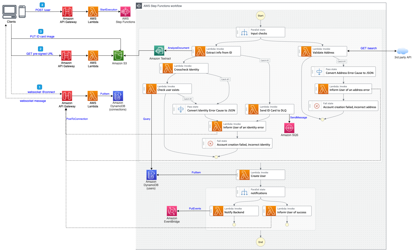
The following diagram illustrates the architecture that we built in the lab.

We collectively defined the following success criteria for the Build Lab:

  • End-to-end data streaming pipeline to ingest on-chain transactions
  • Historical data ingestion of the selected smart contract
  • Data storage and processing of on-chain transactions
  • REST-based APIs to provide time-based metrics for the three defined use cases
  • A sample web UI to display aggregated metrics for the smart contract

Prior to the Build Lab

As a prerequisite for the lab, we configured the data producer application to use the AWS Software Development Kit (AWS SDK) and PUTRecords API operation to send transactions data to an Amazon Simple Storage Service (Amazon S3) bucket. For the Build Lab, we built additional logic within the application to ingest historic transactions data together with real-time transactions data. As a last step, we verified that transactions data was captured and ingested into a test S3 bucket.

AWS services used in the lab

We used the following AWS services as part of the lab:

  • AWS Identity and Access Management (IAM) – We created multiple IAM roles with appropriate trust relationships and necessary permissions that can be used by multiple services to read and write on-chain transactions data and generated logs.
  • Amazon S3 – We created an S3 bucket to store the incoming transactions data as JSON-based files. We created a separate S3 bucket to store incoming transaction data that failed to be transformed and will be reprocessed later.
  • Amazon Kinesis Data Streams – We created a new Kinesis data stream in on-demand mode, which automatically scales based on data ingestion patterns and provides hands-free capacity management. This stream was used by the data producer application to ingest historical and real-time on-chain transactions. We discussed having the ability to manage and predict cost, and therefore were advised to use the provisioned mode when reliable estimates were available for throughput requirements. We were also advised to continue to use on-demand mode until the data traffic patterns were unpredictable.
  • Amazon Kinesis Data Firehose – We created a Firehose delivery stream to transform the incoming data and writes it to the S3 bucket. To minimize latency, we set the delivery stream buffer size to 1 MiB and buffer interval to 60 seconds. This would ensure a file is written to the S3 bucket when either of the two conditions are satisfied regardless of the order. Transactions data written to the S3 bucket was in JSON Lines format.
  • Amazon Simple Queue Service (Amazon SQS) – We set up an SQS queue of the type Standard and an access policy for that SQS queue to allow incoming messages generated from S3 bucket event notifications.
  • Amazon DynamoDB – In order to pick a data store for on-chain transactions, we needed a service that can store transactions payload of unstructured data with varying schemas, provides the ability to cache query results, and is a managed service. We picked DynamoDB for those reasons. We created a single DynamoDB table that holds the incoming transactions data. After analyzing the access query patterns, we decided to use the address field of the smart contract as the partition key and the timestamp field as the sort key. The table was created with auto scaling of read and write capacity modes because the actual usage requirements would be hard to predict at that time.
  • AWS Lambda – We created the following functions:
    • A Python-based Lambda function to perform transformations on the incoming data from the data producer application to flatten the JSON structure, convert the Unix-based epoch timestamp to a date/time value, and convert hex-based string values to a decimal value representing the number of tokens.
    • A second Lambda function to parse incoming SQS queue messages. This message contained values for bucket_name and object_key, which holds the reference to a newly created object within the S3 bucket. The Lambda function logic included parsing of this value to obtain the reference to the S3 object, get the contents of the object, read it into a data frame object using the AWS SDK for pandas (awswrangler) library, convert it into a Pandas data frame object, and use the put_df API call to write a Pandas data frame object as an item into a DynamoDB table. We choose to use Pandas due to familiarity with the library and functions required to perform data transform operations.
    • Three separate Lambda functions that contains the logic to query the DynamoDB table and retrieve items to aggregate and calculate metrics values. This calculated metrics value within the Lambda function was formatted as an HTTP response to expose as REST-based APIs.
  • Amazon API Gateway – We created a REST based API endpoint that uses Lambda proxy integration to pass a smart contract address and time-based interval in minutes as a query string parameter to the backend Lambda function. The response from the Lambda function was a metrics value. We also enabled cross-origin resource sharing (CORS) support within API Gateway to successfully query from the web UI that resides in a different domain.
  • Amazon CloudWatch – We used a Lambda function in-built mechanism to send function metrics to CloudWatch. Lambda functions come with a CloudWatch Logs log group and a log stream for each instance of your function. The Lambda runtime environment sends details of each invocation to the log stream, and relays logs and other output from your function’s code.

Iterative development approach

Across 4 days of the Build Lab, we undertook iterative development. We started by developing the foundational layer and iteratively added extra features through testing and data validation. This allowed us to develop confidence of the solution being built as we tested the output of the metrics through a web-based UI and verified with the actual data. As errors got discovered, we deleted the entire dataset and reran all the jobs to verify results and resolve those errors.

Lab outcomes

In 4 days, we built an end-to-end streaming pipeline ingesting 45 days of historical data and real-time on-chain transactions data for the selected Spooky smart contract. We also developed three REST-based APIs for the selected metrics and a sample web UI that allows users to insert a smart contract address, choose a time frequency, and visualize the metrics values. In a follow-up call, our AWS Data Lab Architect shared post-lab guidance around the next steps required to productionize the solution:

  • Scaling of the proof of concept to handle larger data volumes
  • Security best practices to protect the data while at rest and in transit
  • Best practices for data modeling and storage
  • Building an automated resilience technique to handle failed processing of the transactions data
  • Incorporating high availability and disaster recovery solutions to handle incoming data requests, including adding of the caching layer

Conclusion

Through a short engagement and small team, we accelerated this project from an idea to a solution. This experience gave us the opportunity to explore AWS services and their analytical capabilities in-depth. As a next step, we will continue to take advantage of AWS teams to enhance the solution built during this lab to make it ready for the production deployment.

Learn more about how the AWS Data Lab can help your data and analytics on the cloud journey.


About the Authors

Dr. Quan Hoang Nguyen is currently a CTO at Fantom Foundation. His interests include DLT, blockchain technologies, visual analytics, compiler optimization, and transactional memory. He has experience in R&D at the University of Sydney, IBM, Capital Markets CRC, Smarts – NASDAQ, and National ICT Australia (NICTA).

Ankit Patira is a Data Lab Architect at AWS based in Melbourne, Australia.

Propagating valid mTLS client certificate identity to downstream services using Amazon API Gateway

Post Syndicated from Eric Johnson original https://aws.amazon.com/blogs/compute/propagating-valid-mtls-client-certificate-identity-to-downstream-services-using-amazon-api-gateway/

This blog written by Omkar Deshmane, Senior SA and Anton Aleksandrov, Principal SA, Serverless.

This blog shows how to use Amazon API Gateway with a custom authorizer to process incoming requests, validate the mTLS client certificate, extract the client certificate subject, and propagate it to the downstream application in a base64 encoded HTTP header.

This pattern allows you to terminate mTLS at the edge so downstream applications do not need to perform client certificate validation. With this approach, developers can focus on application logic and offload mTLS certificate management and validation to a dedicated service, such as API Gateway.

Overview

Authentication is one of the core security aspects that you must address when building a cloud application. Successful authentication proves you are who you are claiming to be. There are various common authentication patterns, such as cookie-based authentication, token-based authentication, or the topic of this blog – a certificate-based authentication.

Transport Layer Security (TLS) certificates are at the core of a secure and safe internet. TLS certificates secure the connection between the client and server by encrypting data, ensuring private communication. When using the TLS protocol, the server must prove its identity to the client using a certificate signed by a certificate authority trusted by the client.

Mutual TLS (mTLS) introduces an additional layer of security, in which both the client and server must prove their identities to each other. Developers commonly use mTLS for application-to-application authentication — using digital certificates to represent both client and server apps is a common authentication pattern for building such workflows. We highly recommended decoupling the mTLS implementation from the application business logic so that you do not have to update the application when changing the mTLS configuration. It is a common pattern to implement the mTLS authentication and termination in a network appliance at the edge, such as Amazon API Gateway.

In this solution, we show a pattern of using API Gateway with an authorizer implemented with AWS Lambda to validate the mTLS client certificate, extract the client certificate subject, and propagate it to the downstream application in a base64 encoded HTTP header.

While this blog describes how to implement this pattern for identities extracted from the mTLS client certificates, you can generalize it and apply to propagating information obtained via any other means of authentication.

mTLS Sample Application

This blog includes a sample application implemented using the AWS Serverless Application Model (AWS SAM). It creates a demo environment containing resources like API Gateway, a Lambda authorizer, and an Amazon EC2 instance, which simulates the backend application.

The EC2 instance is used for the backend application to mimic common customer scenarios. You can use any other type of compute, such as Lambda functions or containerized applications with Amazon Elastic Container Service (Amazon ECS) or Amazon Elastic Kubernetes Service (Amazon EKS), as a backend application layer as well.

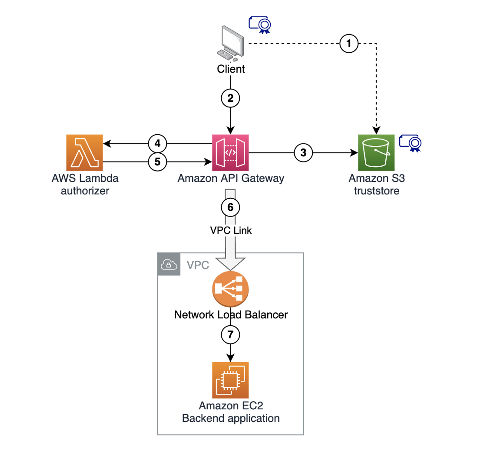
The following diagram shows the solution architecture:

Example architecture diagram

Example architecture diagram

  1. Store the client certificate in a trust store in an Amazon S3 bucket.
  2. The client makes a request to the API Gateway endpoint, supplying the client certificate to establish the mTLS session.
  3. API Gateway retrieves the trust store from the S3 bucket. It validates the client certificate, matches the trusted authorities, and terminates the mTLS connection.
  4. API Gateway invokes the Lambda authorizer, providing the request context and the client certificate information.
  5. The Lambda authorizer extracts the client certificate subject. It performs any necessary custom validation, and returns the extracted subject to API Gateway as a part of the authorization context.
  6. API Gateway injects the subject extracted in the previous step into the integration request HTTP header and sends the request to a downstream endpoint.
  7. The backend application receives the request, extracts the injected subject, and uses it with custom business logic.

Prerequisites and deployment

Some resources created as part of this sample architecture deployment have associated costs, both when running and idle. This includes resources like Amazon Virtual Private Cloud (Amazon VPC), VPC NAT Gateway, and EC2 instances. We recommend deleting the deployed stack after exploring the solution to avoid unexpected costs. See the Cleaning Up section for details.

Refer to the project code repository for instructions to deploy the solution using AWS SAM. The deployment provisions multiple resources, taking several minutes to complete.

Following the successful deployment, refer to the RestApiEndpoint variable in the Output section to locate the API Gateway endpoint. Note this value for testing later.

AWS CloudFormation output

AWS CloudFormation output

Key areas in the sample code

There are two key areas in the sample project code.

In src/authorizer/index.js, the Lambda authorizer code extracts the subject from the client certificate. It returns the value as part of the context object to API Gateway. This allows API Gateway to use this value in the subsequent integration request.

const crypto = require('crypto');

exports.handler = async (event) => {
    console.log ('> handler', JSON.stringify(event, null, 4));

    const clientCertPem = event.requestContext.identity.clientCert.clientCertPem;
    const clientCert = new crypto.X509Certificate(clientCertPem);
    const clientCertSub = clientCert.subject.replaceAll('\n', ',');

    const response = {
        principalId: clientCertSub,
        context: { clientCertSub },
        policyDocument: {
            Version: '2012-10-17',
            Statement: [{
                Action: 'execute-api:Invoke',
                Effect: 'allow',
                Resource: event.methodArn
            }]
        }
    };

    console.log('Authorizer Response', JSON.stringify(response, null, 4));
    return response;
};

In template.yaml, API Gateway injects the client certificate subject extracted by the Lambda authorizer previously into the integration request as X-Client-Cert-Sub HTTP header. X-Client-Cert-Sub is a custom header name and you can choose any other custom header name instead.

SayHelloGetMethod:
    Type: AWS::ApiGateway::Method
    Properties:
      AuthorizationType: CUSTOM
      AuthorizerId: !Ref CustomAuthorizer
      HttpMethod: GET
      ResourceId: !Ref SayHelloResource
      RestApiId: !Ref RestApi
      Integration:
        Type: HTTP_PROXY
        ConnectionType: VPC_LINK
        ConnectionId: !Ref VpcLink
        IntegrationHttpMethod: GET
        Uri: !Sub 'http://${NetworkLoadBalancer.DNSName}:3000/'
        RequestParameters:
          'integration.request.header.X-Client-Cert-Sub': 'context.authorizer.clientCertSub' 

Testing the example

You create a client key and certificate during the deployment, which are stored in the /certificates directory. Use the curl command to make a request to the REST API endpoint using these files.

curl --cert certificates/client.pem --key certificates/client.key \
<use the RestApiEndpoint found in CloudFormation output>
Example flow diagram

Example flow diagram

The client request to API Gateway uses mTLS with a client certificate supplied for mutual TLS authentication. API Gateway uses the Lambda authorizer to extract the certificate subject, and inject it into the Integration request.

The HTTP server runs on the EC2 instance, simulating the backend application. It accepts the incoming request and echoes it back, supplying request headers as part of the response body. The HTTP response received from the backend application contains a simple message and a copy of the request headers sent from API Gateway to the backend.

One header is x-client-cert-sub with the Common Name value you provided to the client certificate during creation. Verify that the value matches the Common Name that you provided when generating the client certificate.

Response example

Response example

API Gateway validated the mTLS client certificate, used the Lambda authorizer to extract the subject common name from the certificate, and forwarded it to the downstream application.

Cleaning up

Use the sam delete command in the api-gateway-certificate-propagation directory to delete the sample application infrastructure:

sam delete

You can also refer to the project code repository for the clean-up instructions.

Conclusion

This blog shows how to use the API Gateway with a Lambda authorizer for mTLS client certificate validation, custom field extraction, and downstream propagation to backend systems. This pattern allows you to terminate mTLS at the edge so that downstream applications are not responsible for client certificate validation.

For additional documentation, refer to Using API Gateway with Lambda Authorizer. Download the sample code from the project code repository. For more serverless learning resources, visit Serverless Land.

Deploying Local Gateway Ingress Routing on AWS Outposts

Post Syndicated from Sheila Busser original https://aws.amazon.com/blogs/compute/deploying-local-gateway-ingress-routing-on-aws-outposts/

This post is written by Leonardo Solano, Senior Hybrid Cloud Solution Architect and Chris Lunsford, Senior Specialist Solutions Architect, AWS Outposts.

AWS Outposts lets customers use the same Amazon Virtual Private Cloud (VPC) security mechanisms, such as security groups and network access control lists, to control traffic flows for on-premises applications running on Outposts. Some customers, desiring additional security or consistency with on-premises systems, want the ability to inspect and filter incoming application traffic as it enters the Outpost. Ideally, they would like to deploy virtual appliances in front of the workloads running on Outposts.

Today, we are announcing a new feature called Outposts local lateway (LGW) ingress routing. This lets you create LGW inbound routes to redirect incoming traffic to an Amazon Elastic Compute Cloud (EC2) Elastic Network Interface (ENI) associated with an EC2 instance running on Outposts rack. The traffic is redirected for inspection before it reaches the workloads running on Outposts rack. Moreover, it lets the EC2 virtual appliance inspect, filter, or optimize the traffic in a similar way as VPC ingress routing in the Region.

Use case

A common use case for this feature is deploying a customer-preferred third-party virtual network appliance. The appliance can inspect, modify, or monitor the incoming traffic for policy compliance and forward compliant traffic on to the workloads running on the Outpost. A typical virtual appliance could be a firewall, intrusion detection system (IDS), or intrusion prevention system (IPS). The features provided by the virtual appliances vary, and they may include deep packet inspection, traffic optimization, and flow monitoring. This new Outposts rack feature modifies the default behavior of the local gateway routing table (LGW-RTB), and it lets customers redirect traffic coming into an Outposts deployment to the virtual appliance.

 Local Gateway Ingress Routing on Outposts Architecture

The new behavior?

Now you can create static routes in the LGW-RTB that target a specific ENI on the Outpost as the next hop. These static routes are propagated toward the customer network through the Border Gateway Protocol (BGP) peering sessions with the Customer Networking Devices. The on-premises network will route traffic to the specified Classless Inter-Domain Routing (CIDR) prefixes, as defined in the static routes, toward the Outposts Network Devices.

 Local Gateway Routing Table

In the preceeding diagram, the static route 198.19.33.248/29 has a longer prefix length than 198.19.33.240/28, and both routes will be propagated toward the customer network via BGP. The incoming traffic for the 198.19.33.248/29 prefix will be directed toward the ENI eni-1234example0. The architecture looks like the following diagram, where the security virtual appliance is seated between the LGW and a set of EC2 instances in Outposts.

Local Gateway Advertised routes

As ingress traffic is routed through the virtual appliance for inspection and filtering, the destination addresses of packets arriving at the ENI of the virtual appliance won’t match its ENI’s private IP address (the packets are transiting the instance). By default, the ENI will drop the inbound traffic unless you disable source/destination checking on the virtual appliance instance ENI settings. The following screenshot shows how you can disable the EC2 instance source/destination checking in the AWS console.

(aka, source-destination-check.png) . EC2 source/destination Check

Considerations for LGW ingress routing

Consider the following requirements when preparing to deploy LGW ingress routing:

  • The ENIs used as the next-hop target must be deployed in an Outposts Subnet.
  • The subnets must belong to a VPC associated with the LGW-RTB.
  • Routes with the longest matches are prioritized. If there are two with the same destination CIDR, then static routes are preferred over propagated ones.

Working with Outposts LGW ingress routing

The following output shows what the LGW route table looks like before applying the ingress routing feature:

{
    "Routes": [
        {
            "DestinationCidrBlock": "0.0.0.0/0",
            "LocalGatewayVirtualInterfaceGroupId": "lgw-vif-grp-XXX",
            "Type": "static",
            "State": "active",
            "LocalGatewayRouteTableId": "lgw-rtb-XXX",
            "LocalGatewayRouteTableArn": "arn:aws:ec2:>AWS-REGION>:<account-id>:local-gateway-route-table/lgw-rtb-XXX",
            "OwnerId": "<account-id>"
        },
        {
            "DestinationCidrBlock": "198.19.33.16/28",
            "CoipPoolId": "coip-pool-0000aaaabbbbcccc1111",
            "Type": "propagated",
            "State": "active",
            "LocalGatewayRouteTableId": "lgw-rtb-XXX",
            "LocalGatewayRouteTableArn": "arn:aws:ec2:<AWS-REGION>:<account-id>:local-gateway-route-table/lgw-XXX",
            "OwnerId": "<account-id>"
        },
        {
            "DestinationCidrBlock": "198.19.33.240/28",
            "CoipPoolId": "coip-pool-0000aaaabbbbcccc2222",
            "Type": "propagated",
            "State": "active",
            "LocalGatewayRouteTableId": "lgw-rtb-XXX",
            "LocalGatewayRouteTableArn": "arn:aws:ec2:<AWS-REGION>:<account-id>:local-gateway-route-table/lgw-XXX",
            "OwnerId": "<account-id>"
        }
     ]
}

The relevant change under an LGW-RTB before to add a local-gateway-route is the presence of the “propagated routes”. This represents the Outposts Subnets that can’t be deleted or modified with Next-Hop as specific ENIs present in Outposts. In the following section, we will cover how it will look after the creation of a local-gateway-route.

Configuring LGW ingress routing

To configure LGW ingress routing, you must provide the LGW route table ID, the ENI ID that will be utilized as a next-hop, and the destination CIDR block. Once you have identified those three parameters, you can configure LGW ingress routing via the This is shown in the following example, where the prefix 198.19.33.248/29 is routed to an Outpost. If the route points to an ENI attached to an instance, then the route will show as active. If the route points to an ENI that isn’t attached to an EC2 instance, then the route will show a blackhole state.

$ aws ec2 create-local-gateway-route \
  --local-gateway-route-table-id <lgw-rtb-id> \
  --network-interface-id <eni-id> \
  --destination-cidr-block 198.19.33.248/29
  
{
    "Route": {
        "DestinationCidrBlock": "198.19.33.248/29",
        "NetworkInterfaceId": "eni-id",
        "Type": "static",
        "State": "active",
        "LocalGatewayRouteTableId": "lgw-rtb-id",
        "LocalGatewayRouteTableArn": "arn:aws:ec2:<AWS-REGION>:<account-id>:local-gateway-route-table/<lgw-rtb-id>",
        "OwnerId": "<account-id>"
    }
}

Once LGW ingress routing has been configured, the LGW will route traffic destined to the 198.19.33.248/29 prefix to the target ENI. This must be present as part of the Outposts subnets. Note that the segment 198.19.33.248/29 is part of the Outposts CIDR range of 198.19.33.240/28. This belongs, in this case, to the Outposts customer-owned IP address (CoIP) CIDRs. When traffic follows a static route to an ENI, the packet destination address is preserved and isn’t translated to the private address of the ENI.

In this case, the new LGW-RTB will look like the following:

{
    "Routes": [
        {
            "DestinationCidrBlock": "0.0.0.0/0",
            "LocalGatewayVirtualInterfaceGroupId": "lgw-vif-grp-XXX",
            "Type": "static",
            "State": "active",
            "LocalGatewayRouteTableId": "lgw-rtb-XXX",
            "LocalGatewayRouteTableArn": "arn:aws:ec2:<AWS-REGION>:<account-id>:local-gateway-route-table/lgw-rtb-XXX",
            "OwnerId": "<account-id>"
        },
        {
            "DestinationCidrBlock": "198.19.33.16/28",
            "CoipPoolId": "coip-pool-0000aaaabbbbcccc1111",
            "Type": "propagated",
            "State": "active",
            "LocalGatewayRouteTableId": "lgw-rtb-XXX",
            "LocalGatewayRouteTableArn": "arn:aws:ec2:<AWS-REGION>:<account-id>:local-gateway-route-table/lgw-XXX",
            "OwnerId": "<account-id>"
        },
        {
            "DestinationCidrBlock": "198.19.33.240/28",
            "CoipPoolId": "coip-pool-0000aaaabbbbcccc1111",
            "Type": "propagated",
            "State": "active",
            "LocalGatewayRouteTableId": "lgw-rtb-XXX",
            "LocalGatewayRouteTableArn": "arn:aws:ec2:<AWS-REGION>:<account-id>:local-gateway-route-table/lgw-XXX",
            "OwnerId": "<account-id>"
        },
         {
            "DestinationCidrBlock": "198.19.33.248/29",
            "NetworkInterfaceId": "eni-XXX",
            "Type": "static",
            "State": "active",
            "LocalGatewayRouteTableId": "lgw-rtb-XXX",
            "LocalGatewayRouteTableArn": "arn:aws:ec2:<AWS-REGION>:<account-id>:local-gateway-route-table/lgw-rtb-XXX",
            "OwnerId": "<account-id>"
        }
     ]
}

In the AWS console, the LGW-RTB will show the new ingress routing route:

 (aka, LWG-RTB) Console Local Gateway Routing Table

Modifying LGW ingress routing

Utilize a similar AWS CLI command to the one that we used previously to create the LGW ingress routing route to modify existing routes. In this case, the command will be aws ec2 modify-local-gateway-route, and the arguments are the same as with the create command. Use this command when you want to shift inbound traffic from one EC2 instance to another – perhaps from an active to a standby network appliance while you perform required maintenance on the primary instance.

$ aws ec2 modify-local-gateway-route \
  --local-gateway-route-table-id <lgw-rtb-id> \
  --network-interface-id <new-eni-id> \
  --destination-cidr-block 198.19.33.248/29
{
    "Route": {
        "DestinationCidrBlock": "198.19.33.248/29",
        "NetworkInterfaceId": "new-eni-id",
        "Type": "static",
        "State": "active",
        "LocalGatewayRouteTableId": "lgw-rtb-id",
        "LocalGatewayRouteTableArn": "arn:aws:ec2:<AWS-REGION>:<account-id>:local-gateway-route-table/<lgw-rtb-id>",
        "OwnerId": "<account-id>"
    }
}

Conclusion

AWS Outposts LGW ingress routing allows AWS customers and partners to deploy virtual appliances on Outposts rack and direct inbound traffic through those appliances. The virtual appliance can inspect, filter, and optimize the ingress traffic before forwarding it on to the workloads running on Outposts rack, creating fine-grained network and security policies for your workloads. To learn more about AWS Outposts rack, visit the product overview page.

Sequence Diagrams enrich your understanding of distributed architectures

Post Syndicated from Kevin Hakanson original https://aws.amazon.com/blogs/architecture/sequence-diagrams-enrich-your-understanding-of-distributed-architectures/

Architecture diagrams visually communicate and document the high-level design of a solution. As the level of detail increases, so does the diagram’s size, density, and layout complexity. Using Sequence Diagrams, you can explore additional usage scenarios and enrich your understanding of the distributed architecture while continuing to communicate visually.

This post takes a sample architecture and iteratively builds out a set of Sequence Diagrams. Each diagram adds to the vocabulary and graphical notation of Sequence Diagrams, then shows how the diagram deepened understanding of the architecture. All diagrams in this post were rendered from a text-based domain specific language using a diagrams-as-code tool instead of being drawn with graphical diagramming software.

Sample architecture

The architecture is based on Implementing header-based API Gateway versioning with Amazon CloudFront from the AWS Compute Blog, which uses the AWS Lambda@Edge feature to dynamically route the request to the targeted API version.

Amazon API Gateway is a fully managed service that makes it easier for developers to create, publish, maintain, monitor, and secure APIs at any scale. Amazon CloudFront is a global content delivery network (CDN) service built for high-speed, low-latency performance, security, and developer ease-of-use. Lambda@Edge lets you run functions that customize the content that CloudFront delivers.

The numbered labels in Figure 1 correspond to the following text descriptions:

  1. User sends an HTTP request to CloudFront, including a version header.
  2. CloudFront invokes the Lambda@Edge function for the Origin Request event.
  3. The function matches the header value to data fetched from an Amazon DynamoDB table, then modifies the Host header and path of the request and returns it to CloudFront.
  4. CloudFront routes the HTTP request to the matching API Gateway.

Figure 1 architecture diagram is a free-form mixture between a structure diagram and a behavior diagram. It includes structural aspects from a high-level Deployment Diagram, which depicts network connections between AWS services. It also demonstrates behavioral aspects from a Communication Diagram, which uses messages represented by arrows labeled with chronological numbers.

High-level architecture diagram

Figure 1. High-level architecture diagram

Sequence Diagrams

Sequence Diagrams are part of a subset of behavior diagrams known as interaction diagrams, which emphasis control and data flow. Sequence Diagrams model the ordered logic of usage scenarios in a consistent visual manner and capture detailed behaviors. I use this diagram type for analysis and design purposes and to validate my assumptions about data flows in distributed architectures. Let’s investigate the system use case where the API is called without a header indicating the requested version using a Sequence Diagram.

Examining the system use case

In Figure 2, User, Web Distribution, and Origin Request are each actors or system participants. The parallel vertical lines underneath these participants are lifelines. The horizontal arrows between participants are messages, with the arrowhead indicating message direction. Messages are arranged in time sequence from top to bottom. The dashed lines represent reply messages. The text inside guillemets («like this») indicate a stereotype, which refines the meaning of a model element. The rectangle with the bent upper-right corner is a note containing additional useful information.

Missing accept-version header

Figure 2. Missing accept-version header

The message from User to Web Distribution lacks any HTTP header that indicates the version, which precipitates the choice of Accept-Version for this name. The return message requires a decision about HTTP status code for this error case (400). The interaction with the Origin Request prompts a selection of Lambda runtimes (nodejs14.x) and understanding the programming model for generating an HTTP response for this request.

Designing the interaction

Next, let’s design the interaction when the Accept-Version header is present, but the corresponding value is not found in the Version Mappings table.

Figure 3 adds new notation to the diagram. The rectangle with “opt” in the upper-left corner and bolded text inside square brackets is an interaction fragment. The “opt” indicates this operation is an option based on the constraint (or guard) that “version mappings not cached” is true.

API version not found

Figure 3. API version not found

A DynamoDB scan operation on every request consumes table read capacity. Caching Version Mappings data inside the Lambda@Edge function’s memory optimizes for on-demand capacity mode. The «on-demand» stereotype on the DynamoDB participant succinctly communicates this decision. The “API V3 not found” note on Figure 3 provides clarity to the reader. The HTTP status code for this error case is decided as 404 with a custom description of “API Version Not Found.”

Now, let’s design the interaction where the API version is found and the caller receives a successful response.

Figure 4 is similar to Figure 3 up until the note, which now indicates “API V1 found.” Consulting the documentation for Writing functions for Lambda@Edge, the request event is updated with the HTTP Host header and path for the “API V1” Amazon API Gateway.

API version found

Figure 4. API version found

Instead of three separate diagrams for these individual scenarios, a single, combined diagram can represent the entire set of use cases. Figure 5 includes two new “alt” interaction fragments that represent choices of alternative behaviors.

The first “alt” has a guard of “missing Accept-Version header” mapping to our Figure 2 use case. The “else” guard encompasses the remaining use cases containing a second “alt” splitting where Figure 3 and Figure 4 diverge. That “version not found” guard is the Figure 3 use case returning the 404, while that “else” guard is the Figure 4 success condition. The added notes improve visual clarity.

Header-based API Gateway versioning with CloudFront

Figure 5. Header-based API Gateway versioning with CloudFront

Diagrams as code

After diagrams are created, the next question is where to save them and how to keep them updated. Because diagrams-as-code use text-based files, they can be stored and versioned in the same source control system as application code. Also consider an architectural decision record (ADR) process to document and communicate architecturally significant decisions. Then as application code is updated, team members can revise both the ADR narrative and the text-based diagram source. Up-to-date documentation is important for operationally supporting production deployments, and these diagrams quickly provide a visual understanding of system component interactions.

Conclusion

This post started with a high-level architecture diagram and ended with an additional Sequence Diagram that captures multiple usage scenarios. This improved understanding of the system design across success and error use cases. Focusing on system interactions prior to coding facilitates the interface definition and emergent properties discovery, before thinking in terms of programming language specific constructs and SDKs.

Experiment to see if Sequence Diagrams improve the analysis and design phase of your next project. View additional examples of diagrams-as-code from the AWS Icons for PlantUML GitHub repository. The Workload Discovery on AWS solution can even build detailed architecture diagrams of your workloads based on live data from AWS.

For vetted architecture solutions and reference architecture diagrams, visit the AWS Architecture Center. For more serverless learning resources, visit Serverless Land.

Related information

  • The Unified Modeling Language specification provides the full definition of Sequence Diagrams. This includes notations for additional interaction frame operators, using open arrow heads to represent asynchronous messages, and more.
  • Diagrams were created for this blog post using PlantUML and the AWS Icons for PlantUML. PlantUML integrates with IDEs, wikis, and other external tools. PlantUML is distributed under multiple open-source licenses, allowing local server rendering for diagrams containing sensitive information. AWS Icons for PlantUML include the official AWS Architecture Icons.

Build a pseudonymization service on AWS to protect sensitive data, part 1

Post Syndicated from Rahul Shaurya original https://aws.amazon.com/blogs/big-data/part-1-build-a-pseudonymization-service-on-aws-to-protect-sensitive-data/

According to an article in MIT Sloan Management Review, 9 out of 10 companies believe their industry will be digitally disrupted. In order to fuel the digital disruption, companies are eager to gather as much data as possible. Given the importance of this new asset, lawmakers are keen to protect the privacy of individuals and prevent any misuse. Organizations often face challenges as they aim to comply with data privacy regulations like Europe’s General Data Protection Regulation (GDPR) and the California Consumer Privacy Act (CCPA). These regulations demand strict access controls to protect sensitive personal data.

This is a two-part post. In part 1, we walk through a solution that uses a microservice-based approach to enable fast and cost-effective pseudonymization of attributes in datasets. The solution uses the AES-GCM-SIV algorithm to pseudonymize sensitive data. In part 2, we will walk through useful patterns for dealing with data protection for varying degrees of data volume, velocity, and variety using Amazon EMR, AWS Glue, and Amazon Athena.

Data privacy and data protection basics

Before diving into the solution architecture, let’s look at some of the basics of data privacy and data protection. Data privacy refers to the handling of personal information and how data should be handled based on its relative importance, consent, data collection, and regulatory compliance. Depending on your regional privacy laws, the terminology and definition in scope of personal information may differ. For example, privacy laws in the United States use personally identifiable information (PII) in their terminology, whereas GDPR in the European Union refers to it as personal data. Techgdpr explains in detail the difference between the two. Through the rest of the post, we use PII and personal data interchangeably.

Data anonymization and pseudonymization can potentially be used to implement data privacy to protect both PII and personal data and still allow organizations to legitimately use the data.

Anonymization vs. pseudonymization

Anonymization refers to a technique of data processing that aims to irreversibly remove PII from a dataset. The dataset is considered anonymized if it can’t be used to directly or indirectly identify an individual.

Pseudonymization is a data sanitization procedure by which PII fields within a data record are replaced by artificial identifiers. A single pseudonym for each replaced field or collection of replaced fields makes the data record less identifiable while remaining suitable for data analysis and data processing. This technique is especially useful because it protects your PII data at record level for analytical purposes such as business intelligence, big data, or machine learning use cases.

The main difference between anonymization and pseudonymization is that the pseudonymized data is reversible (re-identifiable) to authorized users and is still considered personal data.

Solution overview

The following architecture diagram provides an overview of the solution.

Solution overview

This architecture contains two separate accounts:

  • Central pseudonymization service: Account 111111111111 – The pseudonymization service is running in its own dedicated AWS account (right). This is a centrally managed pseudonymization API that provides access to two resources for pseudonymization and reidentification. With this architecture, you can apply authentication, authorization, rate limiting, and other API management tasks in one place. For this solution, we’re using API keys to authenticate and authorize consumers.
  • Compute: Account 222222222222 – The account on the left is referred to as the compute account, where the extract, transform, and load (ETL) workloads are running. This account depicts a consumer of the pseudonymization microservice. The account hosts the various consumer patterns depicted in the architecture diagram. These solutions are covered in detail in part 2 of this series.

The pseudonymization service is built using AWS Lambda and Amazon API Gateway. Lambda enables the serverless microservice features, and API Gateway provides serverless APIs for HTTP or RESTful and WebSocket communication.

We create the solution resources via AWS CloudFormation. The CloudFormation stack template and the source code for the Lambda function are available in GitHub Repository.

We walk you through the following steps:

  1. Deploy the solution resources with AWS CloudFormation.
  2. Generate encryption keys and persist them in AWS Secrets Manager.
  3. Test the service.

Demystifying the pseudonymization service

Pseudonymization logic is written in Java and uses the AES-GCM-SIV algorithm developed by codahale. The source code is hosted in a Lambda function. Secret keys are stored securely in Secrets Manager. AWS Key Management System (AWS KMS) makes sure that secrets and sensitive components are protected at rest. The service is exposed to consumers via API Gateway as a REST API. Consumers are authenticated and authorized to consume the API via API keys. The pseudonymization service is technology agnostic and can be adopted by any form of consumer as long as they’re able to consume REST APIs.

As depicted in the following figure, the API consists of two resources with the POST method:

API Resources

  • Pseudonymization – The pseudonymization resource can be used by authorized users to pseudonymize a given list of plaintexts (identifiers) and replace them with a pseudonym.
  • Reidentification – The reidentification resource can be used by authorized users to convert pseudonyms to plaintexts (identifiers).

The request response model of the API utilizes Java string arrays to store multiple values in a single variable, as depicted in the following code.

Request/Response model

The API supports a Boolean type query parameter to decide whether encryption is deterministic or probabilistic.

The implementation of the algorithm has been modified to add the logic to generate a nonce, which is dependent on the plaintext being pseudonymized. If the incoming query parameters key deterministic has the value True, then the overloaded version of the encrypt function is called. This generates a nonce using the HmacSHA256 function on the plaintext, and takes 12 sub-bytes from a predetermined position for nonce. This nonce is then used for the encryption and prepended to the resulting ciphertext. The following is an example:

  • IdentifierVIN98765432101234
  • NonceNjcxMDVjMmQ5OTE5
  • PseudonymNjcxMDVjMmQ5OTE5q44vuub5QD4WH3vz1Jj26ZMcVGS+XB9kDpxp/tMinfd9

This approach is useful especially for building analytical systems that may require PII fields to be used for joining datasets with other pseudonymized datasets.

The following code shows an example of deterministic encryption.Deterministic Encryption

If the incoming query parameters key deterministic has the value False, then the encrypt method is called without the deterministic parameter and the nonce generated is a random 12 bytes. This generates a different ciphertext for the same incoming plaintext.

The following code shows an example of probabilistic encryption.

Probabilistic Encryption

The Lambda function utilizes a couple of caching mechanisms to boost the performance of the function. It uses Guava to build a cache to avoid generation of the pseudonym or identifier if it’s already available in the cache. For the probabilistic approach, the cache isn’t utilized. It also uses SecretCache, an in-memory cache for secrets requested from Secrets Manager.

Prerequisites

For this walkthrough, you should have the following prerequisites:

Deploy the solution resources with AWS CloudFormation

The deployment is triggered by running the deploy.sh script. The script runs the following phases:

  1. Checks for dependencies.
  2. Builds the Lambda package.
  3. Builds the CloudFormation stack.
  4. Deploys the CloudFormation stack.
  5. Prints to standard out the stack output.

The following resources are deployed from the stack:

  • An API Gateway REST API with two resources:
    • /pseudonymization
    • /reidentification
  • A Lambda function
  • A Secrets Manager secret
  • A KMS key
  • IAM roles and policies
  • An Amazon CloudWatch Logs group

You need to pass the following parameters to the script for the deployment to be successful:

  • STACK_NAME – The CloudFormation stack name.
  • AWS_REGION – The Region where the solution is deployed.
  • AWS_PROFILE – The named profile that applies to the AWS Command Line Interface (AWS CLI). command
  • ARTEFACT_S3_BUCKET – The S3 bucket where the infrastructure code is stored. The bucket must be created in the same account and Region where the solution lives.

Use the following commands to run the ./deployments_scripts/deploy.sh script:

chmod +x ./deployment_scripts/deploy.sh ./deployment_scripts/deploy.sh -s STACK_NAME -b ARTEFACT_S3_BUCKET -r AWS_REGION -p AWS_PROFILE AWS_REGION

Upon successful deployment, the script displays the stack outputs, as depicted in the following screenshot. Take note of the output, because we use it in subsequent steps.

Stack Output

Generate encryption keys and persist them in Secrets Manager

In this step, we generate the encryption keys required to pseudonymize the plain text data. We generate those keys by calling the KMS key we created in the previous step. Then we persist the keys in a secret. Encryption keys are encrypted at rest and in transit, and exist in plain text only in-memory when the function calls them.

To perform this step, we use the script key_generator.py. You need to pass the following parameters for the script to run successfully:

  • KmsKeyArn – The output value from the previous stack deployment
  • AWS_PROFILE – The named profile that applies to the AWS CLI command
  • AWS_REGION – The Region where the solution is deployed
  • SecretName – The output value from the previous stack deployment

Use the following command to run ./helper_scripts/key_generator.py:

python3 ./helper_scripts/key_generator.py -k KmsKeyArn -s SecretName -p AWS_PROFILE -r AWS_REGION

Upon successful deployment, the secret value should look like the following screenshot.

Encryption Secrets

Test the solution

In this step, we configure Postman and query the REST API, so you need to make sure Postman is installed in your machine. Upon successful authentication, the API returns the requested values.

The following parameters are required to create a complete request in Postman:

  • PseudonymizationUrl – The output value from stack deployment
  • ReidentificationUrl – The output value from stack deployment
  • deterministic – The value True or False for the pseudonymization call
  • API_Key – The API key, which you can retrieve from API Gateway console

Follow these steps to set up Postman:

  1. Start Postman in your machine.
  2. On the File menu, choose Import.
  3. Import the Postman collection.
  4. From the collection folder, navigate to the pseudonymization request.
  5. To test the pseudonymization resource, replace all variables in the sample request with the parameters mentioned earlier.

The request template in the body already has some dummy values provided. You can use the existing one or exchange with your own.

  1. Choose Send to run the request.

The API returns in the body of the response a JSON data type.

Reidentification

  1. From the collection folder, navigate to the reidentification request.
  2. To test the reidentification resource, replace all variables in the sample request with the parameters mentioned earlier.
  3. Pass to the response template in the body the pseudonyms output from earlier.
  4. Choose Send to run the request.

The API returns in the body of the response a JSON data type.

Pseudonyms

Cost and performance

There are many factors that can determine the cost and performance of the service. Performance especially can be influenced by payload size, concurrency, cache hit, and managed service limits on the account level. The cost is mainly influenced by how much the service is being used. For our cost and performance exercise, we consider the following scenario:

The REST API is used to pseudonymize Vehicle Identification Numbers (VINs). On average, consumers request pseudonymization of 1,000 VINs per call. The service processes on average 40 requests per second, or 40,000 encryption or decryption operations per second. The average process time per request is as follows:

  • 15 milliseconds for deterministic encryption
  • 23 milliseconds for probabilistic encryption
  • 6 milliseconds for decryption

The number of calls hitting the service per month is distributed as follows:

  • 50 million calls hitting the pseudonymization resource for deterministic encryption
  • 25 million calls hitting the pseudonymization resource for probabilistic encryption
  • 25 million calls hitting the reidentification resource for decryption

Based on this scenario, the average cost is $415.42 USD per month. You may find the detailed cost breakdown in the estimate generated via the AWS Pricing Calculator.

We use Locust to simulate a similar load to our scenario. Measurements from Amazon CloudWatch metrics are depicted in the following screenshots (network latency isn’t considered during our measurement).

The following screenshot shows API Gateway latency and Lambda duration for deterministic encryption. Latency is high at the beginning due to the cold start, and flattens out over time.

API Gateway Latency & Lamdba Duration for deterministic encryption. Latency is high at the beginning due to the cold start and flattens out over time.

The following screenshot shows metrics for probabilistic encryption.

metrics for probabilistic encryption

The following shows metrics for decryption.

metrics for decryption

Clean up

To avoid incurring future charges, delete the CloudFormation stack by running the destroy.sh script. The following parameters are required to run the script successfully:

  • STACK_NAME – The CloudFormation stack name
  • AWS_REGION – The Region where the solution is deployed
  • AWS_PROFILE – The named profile that applies to the AWS CLI command

Use the following commands to run the ./deployment_scripts/destroy.sh script:

chmod +x ./deployment_scripts/destroy.sh ./deployment_scripts/destroy.sh -s STACK_NAME -r AWS_REGION -p AWS_PROFILE

Conclusion

In this post, we demonstrated how to build a pseudonymization service on AWS. The solution is technology agnostic and can be adopted by any form of consumer as long as they’re able to consume REST APIs. We hope this post helps you in your data protection strategies.

Stay tuned for part 2, which will cover consumption patterns of the pseudonymization service.


About the authors

Edvin Hallvaxhiu is a Senior Global Security Architect with AWS Professional Services and is passionate about cybersecurity and automation. He helps customers build secure and compliant solutions in the cloud. Outside work, he likes traveling and sports.

Rahul Shaurya is a Senior Big Data Architect with AWS Professional Services. He helps and works closely with customers building data platforms and analytical applications on AWS. Outside of work, Rahul loves taking long walks with his dog Barney.

Andrea Montanari is a Big Data Architect with AWS Professional Services. He actively supports customers and partners in building analytics solutions at scale on AWS.

María Guerra is a Big Data Architect with AWS Professional Services. Maria has a background in data analytics and mechanical engineering. She helps customers architecting and developing data related workloads in the cloud.

Pushpraj is a Data Architect with AWS Professional Services. He is passionate about Data and DevOps engineering. He helps customers build data driven applications at scale.

Web application access control patterns using AWS services

Post Syndicated from Zili Gao original https://aws.amazon.com/blogs/architecture/web-application-access-control-patterns-using-aws-services/

The web application client-server pattern is widely adopted. The access control allows only authorized clients to access the backend server resources by authenticating the client and providing granular-level access based on who the client is.

This post focuses on three solution architecture patterns that prevent unauthorized clients from gaining access to web application backend servers. There are multiple AWS services applied in these architecture patterns that meet the requirements of different use cases.

OAuth 2.0 authentication code flow

Figure 1 demonstrates the fundamentals to all the architectural patterns discussed in this post. The blog Understanding Amazon Cognito user pool OAuth 2.0 grants describes the details of different OAuth 2.0 grants, which can vary the flow to some extent.

A typical OAuth 2.0 authentication code flow

Figure 1. A typical OAuth 2.0 authentication code flow

The architecture patterns detailed in this post use Amazon Cognito as the authorization server, and Amazon Elastic Compute Cloud instance(s) as resource server. The client can be any front-end application, such as a mobile application, that sends a request to the resource server to access the protected resources.

Pattern 1

Figure 2 is an architecture pattern that offloads the work of authenticating clients to Application Load Balancer (ALB).

Application Load Balancer integration with Amazon Cognito

Figure 2. Application Load Balancer integration with Amazon Cognito

ALB can be used to authenticate clients through the user pool of Amazon Cognito:

  1. The client sends HTTP request to ALB endpoint without authentication-session cookies.
  2. ALB redirects the request to Amazon Cognito authentication endpoint. The client is authenticated by Amazon Cognito.
  3. The client is directed back to the ALB with the authentication code.
  4. The ALB uses the authentication code to obtain the access token from the Amazon Cognito token endpoint and also uses the access token to get client’s user claims from Amazon Cognito UserInfo endpoint.
  5. The ALB prepares the authentication session cookie containing encrypted data and redirects client’s request with the session cookie. The client uses the session cookie for all further requests. The ALB validates the session cookie and decides if the request can be passed through to its targets.
  6. The validated request is forwarded to the backend instances with the ALB adding HTTP headers that contain the data from the access token and user-claims information.
  7. The backend server can use the information in the ALB added headers for granular-level permission control.

The key takeaway of this pattern is that the ALB maintains the whole authentication context by triggering client authentication with Amazon Cognito and prepares the authentication-session cookie for the client. The Amazon Cognito sign-in callback URL points to the ALB, which allows the ALB access to the authentication code.

More details about this pattern can be found in the documentation Authenticate users using an Application Load Balancer.

Pattern 2

The pattern demonstrated in Figure 3 offloads the work of authenticating clients to Amazon API Gateway.

Amazon API Gateway integration with Amazon Cognito

Figure 3. Amazon API Gateway integration with Amazon Cognito

API Gateway can support both REST and HTTP API. API Gateway has integration with Amazon Cognito, whereas it can also have control access to HTTP APIs with a JSON Web Token (JWT) authorizer, which interacts with Amazon Cognito. The ALB can be integrated with API Gateway. The client is responsible for authenticating with Amazon Cognito to obtain the access token.

  1. The client starts authentication with Amazon Cognito to obtain the access token.
  2. The client sends REST API or HTTP API request with a header that contains the access token.
  3. The API Gateway is configured to have:
    • Amazon Cognito user pool as the authorizer to validate the access token in REST API request, or
    • A JWT authorizer, which interacts with the Amazon Cognito user pool to validate the access token in HTTP API request.
  4. After the access token is validated, the REST or HTTP API request is forwarded to the ALB, and:
    • The API Gateway can route HTTP API to private ALB via a VPC endpoint.
    • If a public ALB is used, the API Gateway can route both REST API and HTTP API to the ALB.
  5. API Gateway cannot directly route REST API to a private ALB. It can route to a private Network Load Balancer (NLB) via a VPC endpoint. The private ALB can be configured as the NLB’s target.

The key takeaways of this pattern are:

  • API Gateway has built-in features to integrate Amazon Cognito user pool to authorize REST and/or HTTP API request.
  • An ALB can be configured to only accept the HTTP API requests from the VPC endpoint set by API Gateway.

Pattern 3

Amazon CloudFront is able to trigger AWS Lambda functions deployed at AWS edge locations. This pattern (Figure 4) utilizes a feature of Lambda@Edge, where it can act as an authorizer to validate the client requests that use an access token, which is usually included in HTTP Authorization header.

Using Amazon CloudFront and AWS Lambda@Edge with Amazon Cognito

Figure 4. Using Amazon CloudFront and AWS Lambda@Edge with Amazon Cognito

The client can have an individual authentication flow with Amazon Cognito to obtain the access token before sending the HTTP request.

  1. The client starts authentication with Amazon Cognito to obtain the access token.
  2. The client sends a HTTP request with Authorization header, which contains the access token, to the CloudFront distribution URL.
  3. The CloudFront viewer request event triggers the launch of the function at Lambda@Edge.
  4. The Lambda function extracts the access token from the Authorization header, and validates the access token with Amazon Cognito. If the access token is not valid, the request is denied.
  5. If the access token is validated, the request is authorized and forwarded by CloudFront to the ALB. CloudFront is configured to add a custom header with a value that can only be shared with the ALB.
  6. The ALB sets a listener rule to check if the incoming request has the custom header with the shared value. This makes sure the internet-facing ALB only accepts requests that are forwarded by CloudFront.
  7. To enhance the security, the shared value of the custom header can be stored in AWS Secrets Manager. Secrets Manager can trigger an associated Lambda function to rotate the secret value periodically.
  8. The Lambda function also updates CloudFront for the added custom header and ALB for the shared value in the listener rule.

The key takeaways of this pattern are:

  • By default, CloudFront will remove the authorization header before forwarding the HTTP request to its origin. CloudFront needs to be configured to forward the Authorization header to the origin of the ALB. The backend server uses the access token to apply granular levels of resource access permission.
  • The use of Lambda@Edge requires the function to sit in us-east-1 region.
  • The CloudFront-added custom header’s value is kept as a secret that can only be shared with the ALB.

Conclusion

The architectural patterns discussed in this post are token-based web access control methods that are fully supported by AWS services. The approach offloads the OAuth 2.0 authentication flow from the backend server to AWS services. The services managed by AWS can provide the resilience, scalability, and automated operability for applying access control to a web application.

How to track AWS account metadata within your AWS Organizations

Post Syndicated from Jonathan Nguyen original https://aws.amazon.com/blogs/architecture/how-to-track-aws-account-metadata-within-your-aws-organizations/

United States Automobile Association (USAA) is a San Antonio-based insurance, financial services, banking, and FinTech company supporting millions of military members and their families. USAA has partnered with Amazon Web Services (AWS) to digitally transform and build multiple USAA solutions that help keep members safe and save members’ money and time.

Why build an AWS account metadata solution?

The USAA Cloud Program developed a centralized solution for collecting all AWS account metadata to facilitate core enterprise functions, such as financial management, remediation of vulnerable and insecure configurations, and change release processes for critical application and infrastructure changes.

Companies without centralized metadata solutions may have distributed documents and wikis that contain account metadata, which has to be updated manually. Manually inputting/updating information generally leads to outdated or incorrect metadata and, in addition, requires individuals to reach out to multiple resources and teams to collect specific information.

Solution overview

USAA utilizes AWS Organizations and a series of GitLab projects to create, manage, and baseline all AWS accounts and infrastructure within the organization, including identity and access management, security, and networking components. Within their GitLab projects, each deployment uses a GitLab baseline version that determines what version of the project was provisioned within the AWS account.

During the creation and onboarding of new AWS accounts, which are created for each application team and use-case, there is specific data that is used for tracking and governance purposes, and applied across the enterprise. USAA’s Public Cloud Security team took an opportunity within a hackathon event to develop the solution depicted in Figure 1.

  1. AWS account is created conforming to a naming convention and added to AWS Organizations.

Metadata tracked per AWS account includes:

    • AWS account name
    • Points of contact
    • Line of business (LOB)
    • Cost center #
    • Application ID #
    • Status
    • Cloud governance record #
    • GitLab baseline version
  1. Amazon EventBridge rule invokes AWS Step Functions when new AWS accounts are created.
  2. Step Functions invoke an AWS Lambda function to pull AWS account metadata and load into a centralized Amazon DynamoDB table with Streams enabled to support automation.
  3. A private Amazon API Gateway is exposed to USAA’s internal network, which queries the DynamoDB table and provides AWS account metadata.
Overview of USAA architecture automation workflow to manage AWS account metadata

Figure 1. Overview of USAA architecture automation workflow to manage AWS account metadata

After the solution was deployed, USAA teams leveraged the data in multiple ways:

  1. User interface: a front-end user-interface querying the API Gateway to allow internal users on the USAA network to filter and view metadata for any AWS accounts within AWS Organizations.
  2. Event-driven automation: DynamoDB streams for any changes in the table that would invoke a Lambda function, which would check the most recent version from GitLab and the GitLab baseline version in the AWS account. For any outdated deployments, the Lambda function invokes the CI/CD pipeline for that AWS account to deploy a standardized set of IAM, infrastructure, and security resources and configurations.
  3. Incident response: the Cyber Threat Response team reduces mean-time-to-respond by developing automation to query the API Gateway to append points-of-contact, environment, and AWS account name for custom detections as well as Security Hub and Amazon GuardDuty findings.
  4. Financial management: Internal teams have integrated workflows to their applications to query the API Gateway to return cost center, LOB, and application ID to assist with financial reporting and tracking purposes. This replaces manually reviewing the AWS account metadata from an internal and manually updated wiki page.
  5. Compliance and vulnerability management: automated notification systems were developed to send consolidated reports to points-of-contact listed in the AWS account from the API Gateway to remediate non-compliant resources and configurations.

Conclusion

In this post, we reviewed how USAA enabled core enterprise functions and teams to collect, store, and distribute AWS account metadata by developing a secure and highly scalable serverless application natively in AWS. The solution has been leveraged for multiple use-cases, including internal application teams in USAA’s production AWS environment.

Adding approval notifications to EC2 Image Builder before sharing AMIs

Post Syndicated from Sheila Busser original https://aws.amazon.com/blogs/compute/adding-approval-notifications-to-ec2-image-builder-before-sharing-amis/

This blog post was written by, Glenn Chia Jin Wee, Associate Cloud Architect at AWS and Randall Han, Associate Professional Services Consultant at AWS.

In some situations, you may be required to manually validate the Amazon Machine Image (AMI) built from an Amazon Elastic Compute Cloud (Amazon EC2) Image Builder pipeline before sharing this AMI to other AWS accounts or to an AWS Organization. Currently, Image Builder provides an end-to-end pipeline that automatically shares AMIs after they’ve been built.

In this post, we will walk through the steps to enable approval notifications before AMIs are shared with other AWS accounts. Having a manual approval step could be useful if you would like to verify the AMI configurations before it is shared to other AWS accounts or an AWS Organization. This reduces the possibility of incorrectly configured AMIs being shared to other teams which in turn could lead to downstream issues if applications are installed using this AMI. This solution uses serverless resources to send an email with a link that automatically shares the AMI with the specified AWS accounts. Users select this link after they’ve verified that the AMI is built according to specifications.

Overview

Architecture Diagram

  1. In this solution, an Image Builder Pipeline is run that builds a Golden AMI in Account A. After the AMI is built, Image Builder publishes data about the AMI to an Amazon Simple Notification Service (Amazon SNS) topic.
  2. This SNS Topic passes the data to an AWS Lambda function that subscribes to it.
  3. The Lambda function that subscribes to this topic retrieves the data, formats it, and sends a customized email to another SNS Topic.
  4. The second SNS Topic has an email subscription with the Approver’s email. The approver will receive the customized email with a URL that interacts with the next set of Serverless resources.
  5. Selecting the URL makes a GET request to Amazon API Gateway, thereby passing the AMI ID in the query string.
  6. API Gateway then triggers another Lambda function and passes the AMI ID to it.
  7. The Lambda function obtains the AMI ID from the query string parameter of the API Gateway request, and then shares it with the provided target account.

Prerequisites

For this walkthrough, you will need the following:

Walkthrough

In this section, we will guide you through the steps required to deploy the Image Builder solution that utilizes Serverless resources. The solution is deployed with AWS SAM.

In this scenario, we deploy the solution within the approver’s account. The approval email will be sent to a predefined email address for manual approval, before the newly created AMI is shared to target accounts.

Once the approver selects the approval link, an email notification will be sent to the predefined target account email address, notifying that the AMI has been successfully shared.

The high-level steps we will follow are:

  1. In Account A, deploy the provided AWS SAM template. This includes an example Image Builder Pipeline, Amazon SNS topics, API Gateway, and Lambda functions.
  2. Approve the SNS subscription from your supplied email address.
  3. Run the pipeline from the Amazon EC2 Image Builder Console.
  4. [Optional] After the pipeline runs, launch an Amazon EC2 instance from the built AMI to conduct manual tests
  5. An Amazon SNS email will be sent to you with an API Gateway URL. When clicked, an AWS Lambda function shares the AMI to the Account B.
  6. Log in to Account B and verify that the AMI has been shared.

Step 1: Launch the AWS SAM template

  1. Clone the SAM templates from this GitHub repository.
  2. Run the following command to deploy the templates via SAM. Replace <approver email> with the Approver’s email and <AWS Account B ID> with the AWS Account ID of your second AWS Account.

sam deploy \

–template-file template.yaml \

–stack-name ec2-image-builder-approver-notifications \

–capabilities CAPABILITY_IAM \

–resolve-s3 \

–parameter-overrides \

ApproverEmail=<approver email> \

TargetAccountEmail=<target account email> \

TargetAccountlds=<AWS Account B ID>

Step 2: Verify your email address

  1. After running the deployment, you will receive an email prompting you to confirm the Subscription at the approver email address. Choose Confirm subscription.

Email to confirm SNS topic subscription

  1. This leads to the following screen, which shows that your subscription is confirmed.

SNS topic subscription confirmation

  1. Repeat the previous 2 steps for the target email address.

Step 3: Run the pipeline from the Image Builder console

  1. In the Image Builder console, under Image pipelines, select the checkbox next to the Pipeline created, choose Actions, and select Run pipeline.

Run the Image Builder Pipeline

Note that the pipeline takes approximately 20 to 30 minutes to complete.

Step 4: [Optional] Launch an Amazon EC2 instance from the built AMI

There could be a requirement to manually validate the AMI before sharing it to other AWS accounts or to the AWS organization. With this requirement, approvers will launch an Amazon EC2 instance from the built AMI and conduct manual tests on the EC2 instance to make sure that it is functional.

  1. In the Amazon EC2 console, under Images, choose AMIs. Validate that the AMI is created.

Validate the AMI has been built

  1. Follow AWS docs: Launching an EC2 instances from a custom AMI for steps on how to launch an Amazon EC2 instance from the AMI.

Step 5: Select the approval URL in the email sent

  1. When the pipeline is run successfully, you will receive another email with a URL to share the AMI.

Approval link to share the AMI to Account B

2. Selecting this URL results in the following screen which shows that the AMI share is successful.

Result showing the AMI was successfully shared after selecting the approval link

Step 6: Verify that the AMI is shared to Account B

  1. Log in to Account B.
  2. In the Amazon EC2 console, under Images, choose AMIs. Then, in the dropdown, choose Private images. Validate that the AMI is shared.

AMI is shared when Private images are selected from the dropdown

3. Verify that a success email notification was sent to the target account email address provided.

Successful AMI share email notification sent to Target Account Email Address

Clean up

This section provides the necessary information for deleting various resources created as part of this post.

1. Deregister the AMIs created and shared.

a. Log in to Account A and follow the steps at AWS documentation: Deregister your Linux AMI.

2. Delete the SAM stack with the following command. Replace <region> with the Region of choice.

sam delete –stack-name ec2-image-builder-approver-notifications –no-prompts –region <region>

3. Delete the CloudWatch log groups for the Lambda functions. You’ll identify it with the name `/aws/lambda/ec2-image-builder-approve*`.

4. Consider deleting the Amazon S3 bucket used to store the packaged Lambda artifact.

Conclusion

In this post, we explained how to use Serverless resources to enable approval notifications for an Image Builder pipeline before AMIs are shared to other accounts. This solution can be extended to share to more than one AWS account or even to an AWS organization. With this solution, you will be notified when new golden images are created, allowing you to verify the correctness of their configuration before sharing them to for wider use. This reduces the possibility of sharing AMIs with misconfigurations that the written tests may not have identified.

We invite you to experiment with different AMIs created using Image Builder, and with different Image Builder components. Check out this GitHub repository for various examples that use Image Builder. Also check out this blog on Image builder integrations with EC2 Auto Scaling Instance Refresh. Let us know your questions and findings in the comments, and have fun!

Building resilient private APIs using Amazon API Gateway

Post Syndicated from Eric Johnson original https://aws.amazon.com/blogs/compute/building-resilient-private-apis-using-amazon-api-gateway/

This post written by Giedrius Praspaliauskas, Senior Solutions Architect, Serverless.

Modern architectures meet recovery objectives (recovery time objective, RTO, and recovery point objective, RPO) by being resilient to routine and unexpected infrastructure disruptions. Depending on the recovery objectives and regulatory requirements, developers must choose the disaster recovery strategy. For more on disaster recovery strategies, see this whitepaper.

AWS’ global infrastructure enables customers to support applications with near zero RTO requirements. Customers can run workloads in multiple Regions, in a multi-site active/active manner, and serve traffic from all Regions. To do so, developers often must implement private multi-regional APIs for use by the applications.

This blog describes how to implement this solution using Amazon API Gateway and Amazon Route 53.

Overview

The first step is to build a REST API that uses private API Gateway endpoints with custom domain names as described in this sample. The next step is to deploy APIs in two AWS Regions and configure Route 53, following a disaster recovery strategy.
This architecture uses the following resources in each Region:

Two region architecture example

Two region architecture example

  • API Gateway with an AWS Lambda function as integration target.
  • Amazon Virtual Private Cloud (Amazon VPC) with two private subnets, used to deploy VPC endpoint and Network Load Balancers (NLB).
  • AWS Transit Gateway to establish connectivity between the two VPCs in different Regions.
  • VPC endpoint to access API Gateway from a private VPC.
  • Elastic network interfaces (ENIs) created by the VPC endpoint.
  • A Network Load Balancer with ENIs in its target group and a TLS listener with an AWS Certificate Manager (ACM) certificate, used as a facade for the API.
  • ACM issues and manages certificates used by the NLB TLS listener and API Gateway custom domain.
  • Route 53 with private hosted zones used for DNS resolution.
  • Amazon CloudWatch with alarms used for Route 53 health checks.

This sample implementation uses a Lambda function as an integration target, though it can target on-premises resources accessible via AWS Direct Connect, and applications running on Amazon EKS. For more information on best practices designing API Gateway private APIs, see this whitepaper.

This post uses AWS Transit Gateway with inter-Region peering to establish connectivity between the two VPCs. Depending on the networking needs and infrastructure already in place, you may tailor the architecture and use a different approach. Read this whitepaper for more information on available VPC-to-VPC connectivity options.

Implementation

Prerequisites

You can use existing infrastructure to deploy private APIs. Otherwise check the sample repository for templates and detailed instructions on how to provision the necessary infrastructure.

This post uses the AWS Serverless Application Model (AWS SAM) to deploy private APIs with custom domain names. Visit the documentation to install it in your environment.

Deploying private APIs into multiple Regions

To deploy private APIs with custom domain names and CloudWatch alarms for health checks into the two AWS Regions:

  1. Download the AWS SAM template file api.yaml from the sample repository. Replace default parameter values in the template with ones that match your environment or provide them during the deployment step.
  2. Navigate to the directory containing the template. Run following commands to deploy the API stack in the us-east-1 Region:
    sam build --template-file api.yaml
    sam deploy --template-file api.yaml --guided --stack-name private-api-gateway --region us-east-1
  3. Repeat the deployment in the us-west-2 Region. Update the parameters values in the template to match the second Region (or provide them as an input during the deployment step). Run the following commands:
    sam build --template-file api.yaml
    sam deploy --template-file api.yaml --guided --stack-name private-api-gateway --region us-west-2

Setting up Route 53

With the API stacks deployed in both Regions, create health checks to use them in Route 53:

  1. Navigate to Route 53 in the AWS Management Console. Use the CloudWatch alarms created in the previous step to create health checks (one per Region):
    Configuring the health check for region 1

    Configuring the health check for region 1

    Configuring the health check for region 2

    Configuring the health check for region 2

    This Route 53 health check uses the CloudWatch alarms that are based on a static threshold of the NLB healthy host count metric in each Region. In your implementation, you may need more sophisticated API health status tracking. It can use anomaly detection, include metric math, or use a composite state of the multiple alarms. Check this documentation article for more information on CloudWatch alarms. You can also use the approach documented in this blog post as an alternative. It will help you to create a health check solution that observes the state of the private resources and creates custom metrics that are more specific to your use case. For example, such metrics could include increased database transactions’ failure rate, number of timed out requests to a downstream legacy system, status of an external system that your workload depends on, etc.

  2. Create a private Route 53 hosted zone. Associate this with the VPCs where the client applications that access private APIs reside:

    Create a private hosted zone

    Create a private hosted zone

  3. Create Route 53 private zone alias records, pointing to the NLBs in both Regions and VPCs, using the same name for both records (for example, private.internal.example.com):

    Create alias records

    Create alias records

This post uses Route 53 latency-based routing for private DNS to implement resilient active-active private API architecture. Depending on your use case and disaster recovery strategy, you can change this approach and use geolocation-based routing, failover, or weighted routing. See the documentation for more details on supported routing policies for the records in a private hosted zone.

In this implementation, client applications that connect to the private APIs reside in the VPCs and can access Route 53 private hosted zones. You may also operate an application that runs on-premises and must access the private APIs. Read this blog post for more information on how to create DNS naming that spans the entire network.

Validating the configuration

To validate this implementation, I use a bastion instance in each of the VPCs. I connect to them using SSH or AWS Systems Manager Session Manager (see this documentation article for details).

  1. Run the following command from both bastion instances:
    dig +short private.internal.com

    The response should contain IP addresses of the NLB in one VPC:

    10.2.2.188
    10.2.1.211
  2. After DNS resolution verification, run the following command in each of the VPCs:
    curl -s -XGET https://private.internal.example.com/demo

    The response should include event data as the Lambda function received it.

  3. To simulate an outage, navigate to Route 53 in the AWS Management Console. Select the health check that corresponds to the Region where you received the response, and invert the health status:
  4. After a few minutes, retry the same DNS resolution and API response validation steps. This time, it routes all your requests to the remaining healthy API stack.

Cleaning Up

To avoid incurring further charges, delete all the resources that you have created in Route 53 records, health checks, and private hosted zones.

Run the following commands to delete API stacks in both Regions:

sam delete --stack-name private-api-gateway --region us-west-2
sam delete --stack-name private-api-gateway --region us-east-1

If you used the sample templates to provision the infrastructure, follow the steps listed in the Cleanup section of the sample repository instructions.

Conclusion

This blog post walks through implementing a multi-Regional private API using API Gateway with custom domain names. This approach allows developers to make their internal applications and workloads more resilient, react to disruptions, and meet their disaster recovery scenario objectives.

For additional guidance on such architectures, including multi-Region application architecture, see this solutionblog post, re:Invent presentation.

For more serverless learning resources, visit Serverless Land.

Implementing lightweight on-premises API connectivity using inverting traffic proxy

Post Syndicated from Oleksiy Volkov original https://aws.amazon.com/blogs/architecture/implementing-lightweight-on-premises-api-connectivity-using-inverting-traffic-proxy/

This post will explore the use of lightweight application inversion proxy as a solution for multi-point hybrid or multi-cloud, API-level connectivity for cases where AWS Direct Connect or VPN may not be practical. Then, we will present a sample solution and explain how it addresses typical challenges involved in this space.

Defining the issue

Large ISV providers and integration vendors often need to have API-level integration between a central cloud-based system and a number of on-premises APIs. Use cases can range from refactoring/modernization initiatives to interfacing with legacy on-premises applications, which have no direct migration path to the cloud.

The typical approach is to use VPN or Direct Connect, as they can provide significant benefits in terms of latency and security. However, they are not always practical in situations involving multi-source systems deployed by various groups or organizations that may have significant budget, process, or timeline constraints.

Conceptual solution

An option that addresses the connectivity need is an inverting application proxy, which can be deployed as a lightweight executable on an on-premises backend. The locally deployed agent can communicate with the proxy server on AWS using an inverted communication pattern. This means that the agent will establish outbound connection to the proxy, and it will use the connection to receive inbound requests, too. Figure 1 describes a sample architecture using inverting proxy pattern using Amazon API Gateway façade.

Inverting application proxy

Figure 1. Inverting application proxy

The advantages of this approach include ease-of-deployment (drop-in executable agent) and -configuration. As the proxy inverts the direction of application connectivity to originate from on-premises servers, the local firewall does not need to be reconfigured to open additional ports needed for traditional proxy deployment.

Realizing the solution on AWS

We have built a sample traffic routing solution based on the original open-source Inverting Proxy and Agent by Ian Maddox, Jason Cooke, and Omar Janjur. The solution is written in Go and leverages multiple AWS services to provide additional telemetry, security, and discoverability capabilities that address the common needs of enterprise customers.

The solution is comprised of an inverting proxy and a forwarding agent. The inverting proxy is deployed on AWS as a stand-alone executable running on Amazon Elastic Compute Cloud (EC2) and responsible for forwarding traffic to the agent. The agent can be deployed as a binary or container within the target on-premises system.

Upon starting, the agent will establish an outbound connection with the proxy and local sever application. Once established, the proxy will use it in reverse to forward all incoming client requests through the agent and to the backend application. The connection is secured by Transport Layer Security (TLS) to protect communications between client and proxy and between agent and backend application.

This solution uses a unique backend ID and IAM user/role tags to identify different backend servers and control access to proxies. The backend ID is passed as a command-line parameter to the agent. The agent checks the IAM account or IAM role Amazon EC2 is running under for tag “AllowedBackends”. The tag contains coma-separated list of backend IDs that the agent is allowed to access. The connectivity is established only if the provided backend ID matches one of the values in the coma-separated list.

The solution supports native integration with AWS Cloud Map to enable automatic discoverability of remote API endpoints. Upon start and once the IAM access control checks are successfully validated, the agent can register the backend endpoints within AWS Cloud Map using a provided service name and service namespace ID.

Inverting proxy agent can collect telemetry and automatically publish it to Amazon CloudWatch using a custom namespace. This includes HTTP response codes and counts from server application aggregated by the backend ID.

For full list of options, features, and supported configurations, use --help command-line parameter with both agent and proxy executables.

Enabling highly resilient proxy deployment

For production scenarios that require high availability, deploy a pair of inverting proxies connecting to a pair of agents deployed on separate EC2 instances. The entire configuration is then placed behind Application Load Balancer to provide a single point of ingress, load-balancing, and health-checking functionality. Figure 2 demonstrates a highly resilient setup for critical workloads.

Highly resilient deployment diagram for inverting proxy

Figure 2. Highly resilient deployment diagram for inverting proxy

Additionally, for real-life production workloads dealing with sensitive data, we recommend following security and resilience best practices for Amazon EC2.

Deploying and running the solution

The solution includes a simple demo Node.js server application to simulate connectivity with an inverting proxy. A restrictive security group will be used to simulate on-premises data center.

Steps to deployment:

1. Create a “backend” Amazon EC2 server using Linux 2, free-tier AMI. Ensure that Port 443 (inbound port for sample server application) is blocked from external access via appropriate security group.

2. Connect by using SSH into target server run updates.

sudo yum update -y

3. Install development tools and dependencies:

sudo yum groupinstall "Development Tools" -y

4. Install Golang:

sudo yum install golang -y

5. Install node.js.

curl -o- https://raw.githubusercontent.com/nvm-sh/nvm/v0.34.0/install.sh | bash

. ~/.nvm/nvm.sh

nvm install 16

6. Clone the inverting proxy GitHub repository to the “backend” EC2 instance.

7. From inverting-proxy folder, build the application by running:

mkdir /home/ec2-user/inverting-proxy/bin

export GOPATH=/home/ec2-user/inverting-proxy/bin

make

8. From /simple-server folder, run the sample appTLS application in the background (see instructions below). Note: to enable SSL you will need to generate encryption key and certificate files (server.crt and server.key) and place them in simple-server folder.

npm install

node appTLS &

Example app listening at https://localhost:443

Confirm that the application is running by using ps -ef | grep node:

ec2-user  1700 30669  0 19:45 pts/0    00:00:00 node appTLS

ec2-user  1708 30669  0 19:45 pts/0    00:00:00 grep --color=auto node

9. For backend Amazon EC2 server, navigate to Amazon EC2 security settings and create an IAM role for the instance. Keep default permissions and add “AllowedBackends” tag with the backend ID as a tag value (the backend ID can be any string that matches the backend ID parameter in Step 13).

10. Create a proxy Amazon EC2 server using Linux AMI in a public subnet and connect by using SSH in an Amazon EC2 once online. Copy the contents of the bin folder from the agent EC2 or clone the repository and follow build instructions above (Steps 2-7).

Note: the agent will be establishing outbound connectivity to the proxy; open the appropriate port (443) in the proxy Amazon EC2 security group. The proxy server needs to be accessible by the backend Amazon EC2 and your client workstation, as you will use your local browser to test the application.

11. To enable TLS encryption on incoming connections to proxy, you will need to generate and upload the certificate and private key (server.crt and server.key) to the bin folder of the proxy deployment.

12. Navigate to /bin folder of the inverting proxy and start the proxy by running:

sudo ./proxy –port 443 -tls

2021/12/19 19:56:46 Listening on [::]:443

13. Use the SSH to connect into the backend Amazon EC2 server and configure the inverting proxy agent. Navigate to /bin folder in the cloned repository and run the command below, replacing uppercase strings with the appropriate values. Note: the required trailing slash after the proxy DNS URL.

./proxy-forwarding-agent -proxy https://YOUR_PROXYSERVER_PUBLIC_DNS/ -backend SampleBackend-host localhost:443 -scheme https

14. Use your local browser to navigate to proxy server public DNS name (https://YOUR_PROXYSERVER_PUBLIC_DNS). You should see the following response from your sample backend application:

Hello World!

Conclusion

Inverting proxy is a flexible, lightweight pattern that can be used for routing API traffic in non-trivial hybrid and multi-cloud scenarios that do not require low-latency connectivity. It can also be used for securing existing endpoints, refactoring legacy applications, and enabling visibility into legacy backends. The sample solution we have detailed can be customized to create unique implementations and provides out-of-the-box baseline integration with multiple AWS services.

Use direct service integrations to optimize your architecture

Post Syndicated from Jerome Van Der Linden original https://aws.amazon.com/blogs/architecture/use-direct-service-integrations-to-optimize-your-architecture/

When designing an application, you must integrate and combine several AWS services in the most optimized way for an effective and efficient architecture:

  • Optimize for performance by reducing the latency between services
  • Optimize for costs operability and sustainability, by avoiding unnecessary components and reducing workload footprint
  • Optimize for resiliency by removing potential point of failures
  • Optimize for security by minimizing the attack surface

As stated in the Serverless Application Lens of the Well-Architected Framework, “If your AWS Lambda function is not performing custom logic while integrating with other AWS services, chances are that it may be unnecessary.” In addition, Amazon API Gateway, AWS AppSync, AWS Step Functions, Amazon EventBridge, and Lambda Destinations can directly integrate with a number of services. These optimizations can offer you more value and less operational overhead.

This blog post will show how to optimize an architecture with direct integration.

Workflow example and initial architecture

Figure 1 shows a typical workflow for the creation of an online bank account. The customer fills out a registration form with personal information and adds a picture of their ID card. The application then validates ID and address, and scans if there is already an existing user by that name. If everything checks out, a backend application will be notified to create the account. Finally, the user is notified of successful completion.

Figure 1. Bank account application workflow

Figure 1. Bank account application workflow

The workflow architecture is shown in Figure 2 (click on the picture to get full resolution).

Figure 2. Initial account creation architecture

Figure 2. Initial account creation architecture

This architecture contains 13 Lambda functions. If you look at the code on GitHub, you can see that:

Five of these Lambda functions are basic and perform simple operations:

Additional Lambda functions perform other tasks, such as verification and validation:

  • One function generates a presigned URL to upload ID card pictures to Amazon Simple Storage Service (Amazon S3)
  • One function uses the Amazon Textract API to extract information from the ID card
  • One function verifies the identity of the user against the information extracted from the ID card
  • One function performs simple HTTP request to a third-party API to validate the address

Finally, four functions concern the websocket (connect, message, and disconnect) and notifications to the user.

Opportunities for improvement

If you further analyze the code of the five basic functions (see startWorkflow on GitHub, for example), you will notice that there are actually three lines of fundamental code that start the workflow. The others 38 lines involve imports, input validation, error handling, logging, and tracing. Remember that all this code must be tested and maintained.

import os
import json
import boto3
from aws_lambda_powertools import Tracer
from aws_lambda_powertools import Logger
import re

logger = Logger()
tracer = Tracer()

sfn = boto3.client('stepfunctions')

PATTERN = re.compile(r"^arn:(aws[a-zA-Z-]*)?:states:[a-z]{2}((-gov)|(-iso(b?)))?-[a-z]+-\d{1}:\d{12}:stateMachine:[a-zA-Z0-9-_]+$")

if ('STATE_MACHINE_ARN' not in os.environ
    or os.environ['STATE_MACHINE_ARN'] is None
    or not PATTERN.match(os.environ['STATE_MACHINE_ARN'])):
    raise RuntimeError('STATE_MACHINE_ARN env var is not set or incorrect')

STATE_MACHINE_ARN = os.environ['STATE_MACHINE_ARN']

@logger.inject_lambda_context
@tracer.capture_lambda_handler
def handler(event, context):
    try:
        event['requestId'] = context.aws_request_id

        sfn.start_execution(
            stateMachineArn=STATE_MACHINE_ARN,
            input=json.dumps(event)
        )

        return {
            'requestId': event['requestId']
        }
    except Exception as error:
        logger.exception(error)
        raise RuntimeError('Internal Error - cannot start the creation workflow') from error

After running this workflow several times and reviewing the AWS X-Ray traces (Figure 3), we can see that it takes about 2–3 seconds when functions are warmed:

Figure 3. X-Ray traces when Lambda functions are warmed

Figure 3. X-Ray traces when Lambda functions are warmed

But the process takes around 10 seconds with cold starts, as shown in Figure 4:

Figure 4. X-Ray traces when Lambda functions are cold

Figure 4. X-Ray traces when Lambda functions are cold

We use an asynchronous architecture to avoid waiting time for the user, as this can be a long process. We also use WebSockets to notify the user when it’s finished. This adds some complexity, new components, and additional costs to the architecture. Now let’s look at how we can optimize this architecture.

Improving the initial architecture

Direct integration with Step Functions

Step Functions can directly integrate with some AWS services, including DynamoDB, Amazon SQS, and EventBridge, and more than 10,000 APIs from 200+ AWS services. With these integrations, you can replace Lambda functions when they do not provide value. We recommend using Lambda functions to transform data, not to transport data from one service to another.

In our bank account creation use case, there are four Lambda functions we can replace with direct service integrations (see large arrows in Figure 5):

  • Query a DynamoDB table to search for a user
  • Send a message to an SQS queue when the extraction fails
  • Create the user in DynamoDB
  • Send an event on EventBridge to notify the backend
Figure 5. Lambda functions that can be replaced

Figure 5. Lambda functions that can be replaced

It is not as clear that we need to replace the other Lambda functions. Here are some considerations:

  • To extract information from the ID card, we use Amazon Textract. It is available through the SDK integration in Step Functions. However, the API’s response provides too much information. We recommend using a library such as amazon-textract-response-parser to parse the result. For this, you’ll need a Lambda function.
  • The identity cross-check performs a simple comparison between the data provided in the web form and the one extracted in the ID card. We can perform this comparison in Step Functions using a Choice state and several conditions. If the business logic becomes more complex, consider using a Lambda function.
  • To validate the address, we query a third-party API. Step Functions cannot directly call a third-party HTTP endpoint, but because it’s integrated with API Gateway, we can create a proxy for this endpoint.

If you only need to retrieve data from an API or make a simple API call, use the direct integration. If you need to implement some logic, use a Lambda function.

Direct integration with API Gateway

API Gateway also provides service integrations. In particular, we can start the workflow without using a Lambda function. In the console, select the integration type “AWS Service”, the AWS service “Step Functions”, the action “StartExecution”, and “POST” method, as shown in Figure 6.

Figure 6. API Gateway direct integration with Step Functions

Figure 6. API Gateway direct integration with Step Functions

After that, use a mapping template in the integration request to define the parameters as shown here:

{
  "stateMachineArn":"arn:aws:states:eu-central-1:123456789012:stateMachine: accountCreationWorkflow",
  "input":"$util.escapeJavaScript($input.json('$'))"
}

We can go further and remove the websockets and associated Lambda functions connect, message, and disconnect. By using Synchronous Express Workflows and the StartSyncExecution API, we can start the workflow and wait for the result in a synchronous fashion. API Gateway will then directly return the result of the workflow to the client.

Final optimized architecture

After applying these optimizations, we have the updated architecture shown in Figure 7. It uses only two Lambda functions out of the initial 13. The rest have been replaced by direct service integrations or implemented in Step Functions.

Figure 7. Final optimized architecture

Figure 7. Final optimized architecture

We were able to remove 11 Lambda functions and their associated fees. In this architecture, the cost is mainly driven by Step Functions, and the main price difference will be your use of Express Workflows instead of Standard Workflows. If you need to keep some Lambda functions, use AWS Lambda Power Tuning to configure your function correctly and benefit from the best price/performance ratio.

One of the main benefits of this architecture is performance. With the final workflow architecture, it now takes about 1.5 seconds when the Lambda function is warmed and 3 seconds on cold starts (versus up to 10 seconds previously), see Figure 8:

Figure 8. X-Ray traces for the final architecture

Figure 8. X-Ray traces for the final architecture

The process can now be synchronous. It reduces the complexity of the architecture and vastly improves the user experience.

An added benefit is that by reducing the overall complexity and removing the unnecessary Lambda functions, we have also reduced the risk of failures. These can be errors in the code, memory or timeout issues due to bad configuration, lack of permissions, network issues between components, and more. This increases the resiliency of the application and eases its maintenance.

Testing

Testability is an important consideration when building your workflow. Unit testing a Lambda function is straightforward, and you can use your preferred testing framework and validate methods. Adopting a hexagonal architecture also helps remove dependencies to the cloud.

When removing functions and using an approach with direct service integrations, you are by definition directly connected to the cloud. You still must verify that the overall process is working as expected, and validate these integrations.

You can achieve this kind of tests locally using Step Functions Local, and the recently announced Mocked Service Integrations. By mocking service integrations, for example, retrieving an item in DynamoDB, you can validate the different paths of your state machine.

You also have to perform integration tests, but this is true whether you use direct integrations or Lambda functions.

Conclusion

This post describes how to simplify your architecture and optimize for performance, resiliency, and cost by using direct integrations in Step Functions and API Gateway. Although many Lambda functions were reduced, some remain useful for handling more complex business logic and data transformation. Try this out now by visiting the GitHub repository.

For further reading:

Throttling a tiered, multi-tenant REST API at scale using API Gateway: Part 2

Post Syndicated from Nick Choi original https://aws.amazon.com/blogs/architecture/throttling-a-tiered-multi-tenant-rest-api-at-scale-using-api-gateway-part-2/

In Part 1 of this blog series, we demonstrated why tiering and throttling become necessary at scale for multi-tenant REST APIs, and explored tiering strategy and throttling with Amazon API Gateway.

In this post, Part 2, we will examine tenant isolation strategies at scale with API Gateway and extend the sample code from Part 1.

Enhancing the sample code

To enable this functionality in the sample code (Figure 1), we will make manual changes. First, create one API key for the Free Tier and five API keys for the Basic Tier. Currently, these API keys are private keys for your Amazon Cognito login, but we will make a further change in the backend business logic that will promote them to pooled resources. Note that all of these modifications are specific to this sample code’s implementation; the implementation and deployment of a production code may be completely different (Figure 1).

Cloud architecture of the sample code

Figure 1. Cloud architecture of the sample code

Next, in the business logic for thecreateKey(), find the AWS Lambda function in lambda/create_key.js.  It appears like this:

function createKey(tableName, key, plansTable, jwt, rand, callback) {
  const pool = getPoolForPlanId( key.planId ) 
  if (!pool) {
    createSiloedKey(tableName, key, plansTable, jwt, rand, callback);
  } else {
    createPooledKey(pool, tableName, key, jwt, callback);
  }
}

The getPoolForPlanId() function does a search for a pool of keys associated with the usage plan. If there is a pool, we “create” a kind of reference to the pooled resource, rather than a completely new key that is created by the API Gateway service directly. The lambda/api_key_pools.js should be empty.

exports.apiKeyPools = [];

In effect, all usage plans were considered as siloed keys up to now. To change that, populate the data structure with values from the six API keys that were created manually. You will have to look up the IDs of the API keys and usage plans that were created in API Gateway (Figures 2 and 3). Using the AWS console to navigate to API Gateway is the most intuitive.

A view of the AWS console when inspecting the ID for the Basic usage plan

Figure 2. A view of the AWS console when inspecting the ID for the Basic usage plan

A view of the AWS Console when looking up the API key value (not the ID)

Figure 3. A view of the AWS Console when looking up the API key value (not the ID)

When done, your code in lambda/api_key_pools.js should be the following, but instead of ellipses (), the IDs for the user plans and API keys specific to your environment will appear.

exports.apiKeyPools = [{
    planName: "FreePlan"
    planId: "...",
    apiKeys: [ "..." ]
  },
 {
    planName: "BasicPlan"
    planId: "...",
    apiKeys: [ "...", "...", "...", "...", "..." ]
  }];

After making the code changes, run cdk deploy from the command line to update the Lambda functions. This change will only affect key creation and deletion because of the system implementation. Updates affect only the user’s specific reference to the key, not the underlying resource managed by API Gateway.

When the web application is run now, it will look similar to before—tenants should not be aware what tiering strategy they have been assigned to. The only way to notice the difference would be to create two Free Tier keys, test them, and note that the value of the X-API-KEY header is unchanged between the two.

Now, you have a virtually unlimited number of users who can have API keys in the Free or Basic Tier. By keeping the Premium Tier siloed, you are subject to the 10,000-API-key maximum (less any keys allocated for the lower tiers). You may consider additional techniques to continue to scale, such as replicating your service in another AWS account.

Other production considerations

The sample code is minimal, and it illustrates just one aspect of scaling a Software-as-a-service (SaaS) application. There are many other aspects be considered in a production setting that we explore in this section.

The throttled endpoint, GET /api rely only on API key for authorization for demonstration purpose. For any production implementation consider authentication options for your REST APIs. You may explore and extend to require authentication with Cognito similar to /admin/* endpoints in the sample code.

One API key for Free Tier access and five API keys for Basic Tier access are illustrative in a sample code but not representative of production deployments. Number of API keys with service quota into consideration, business and technical decisions may be made to minimize noisy neighbor effect such as setting blast radius upper threshold of 0.1% of all users. To satisfy that requirement, each tier would need to spread users across at least 1,000 API keys. The number of keys allocated to Basic or Premium Tier would depend on market needs and pricing strategies. Additional allocations of keys could be held in reserve for troubleshooting, QA, tenant migrations, and key retirement.

In the planning phase of your solution, you will decide how many tiers to provide, how many usage plans are needed, and what throttle limits and quotas to apply. These decisions depend on your architecture and business.

To define API request limits, examine the system API Gateway is protecting and what load it can sustain. For example, if your service will scale up to 1,000 requests per second, it is possible to implement three tiers with a 10/50/40 split: the lowest tier shares one common API key with a 100 request per second limit; an intermediate tier has a pool of 25 API keys with a limit of 20 requests per second each; and the highest tier has a maximum of 10 API keys, each supporting 40 requests per second.

Metrics play a large role in continuously evolving your SaaS-tiering strategy (Figure 4). They provide rich insights into how tenants are using the system. Tenant-aware and SaaS-wide metrics on throttling and quota limits can be used to: assess tiering in-place, if tenants’ requirements are being met, and if currently used tenant usage profiles are valid (Figure 5).

Tiering strategy example with 3 tiers and requests allocation per tier

Figure 4. Tiering strategy example with 3 tiers and requests allocation per tier

An example SaaS metrics dashboard

Figure 5. An example SaaS metrics dashboard

API Gateway provides options for different levels of granularity required, including detailed metrics, and execution and access logging to enable observability of your SaaS solution. Granular usage metrics combined with underlying resource consumption leads to managing optimal experience for your tenants with throttling levels and policies per method and per client.

Cleanup

To avoid incurring future charges, delete the resources. This can be done on the command line by typing:

cd ${TOP}/cdk
cdk destroy

cd ${TOP}/react
amplify delete

${TOP} is the topmost directory of the sample code. For the most up-to-date information, see the README.md file.

Conclusion

In this two-part blog series, we have reviewed the best practices and challenges of effectively guarding a tiered multi-tenant REST API hosted in AWS API Gateway. We also explored how throttling policy and quota management can help you continuously evaluate the needs of your tenants and evolve your tiering strategy to protect your backend systems from being overwhelmed by inbound traffic.

Further reading:

Throttling a tiered, multi-tenant REST API at scale using API Gateway: Part 1

Post Syndicated from Nick Choi original https://aws.amazon.com/blogs/architecture/throttling-a-tiered-multi-tenant-rest-api-at-scale-using-api-gateway-part-1/

Many software-as-a-service (SaaS) providers adopt throttling as a common technique to protect a distributed system from spikes of inbound traffic that might compromise reliability, reduce throughput, or increase operational cost. Multi-tenant SaaS systems have an additional concern of fairness; excessive traffic from one tenant needs to be selectively throttled without impacting the experience of other tenants. This is also known as “the noisy neighbor” problem. AWS itself enforces some combination of throttling and quota limits on nearly all its own service APIs. SaaS providers building on AWS should design and implement throttling strategies in all of their APIs as well.

In this two-part blog series, we will explore tiering and throttling strategies for multi-tenant REST APIs and review tenant isolation models with hands-on sample code. In part 1, we will look at why a tiering and throttling strategy is needed and show how Amazon API Gateway can help by showing sample code. In part 2, we will dive deeper into tenant isolation models as well as considerations for production.

We selected Amazon API Gateway for this architecture since it is a fully managed service that helps developers to create, publish, maintain, monitor, and secure APIs. First, let’s focus on how Amazon API Gateway can be used to throttle REST APIs with fine granularity using Usage Plans and API Keys. Usage Plans define the thresholds beyond which throttling should occur. They also enable quotas, which sets a maximum usage per a day, week, or month. API Keys are identifiers for distinguishing traffic and determining which Usage Plans to apply for each request. We limit the scope of our discussion to REST APIs because other protocols that API Gateway supports — WebSocket APIs and HTTP APIs — have different throttling mechanisms that do not employ Usage Plans or API Keys.

SaaS providers must balance minimizing cost to serve and providing consistent quality of service for all tenants. They also need to ensure one tenant’s activity does not affect the other tenants’ experience. Throttling and quotas are a key aspect of a tiering strategy and important for protecting your service at any scale. In practice, this impact of throttling polices and quota management is continuously monitored and evaluated as the tenant composition and behavior evolve over time.

Architecture Overview

Figure 1. Cloud Architecture of the sample code.

Figure 1 – Architecture of the sample code

To get a firm foundation of the basics of throttling and quotas with API Gateway, we’ve provided sample code in AWS-Samples on GitHub. Not only does it provide a starting point to experiment with Usage Plans and API Keys in the API Gateway, but we will modify this code later to address complexity that happens at scale. The sample code has two main parts: 1) a web frontend and, 2) a serverless backend. The backend is a serverless architecture using Amazon API Gateway, AWS Lambda, Amazon DynamoDB, and Amazon Cognito. As Figure I illustrates, it implements one REST API endpoint, GET /api, that is protected with throttling and quotas. There are additional APIs under the /admin/* resource to provide Read access to Usage Plans, and CRUD operations on API Keys.

All these REST endpoints could be tested with developer tools such as curl or Postman, but we’ve also provided a web application, to help you get started. The web application illustrates how tenants might interact with the SaaS application to browse different tiers of service, purchase API Keys, and test them. The web application is implemented in React and uses AWS Amplify CLI and SDKs.

Prerequisites

To deploy the sample code, you should have the following prerequisites:

For clarity, we’ll use the environment variable, ${TOP}, to indicate the top-most directory in the cloned source code or the top directory in the project when browsing through GitHub.

Detailed instructions on how to install the code are in ${TOP}/INSTALL.md file in the code. After installation, follow the ${TOP}/WALKTHROUGH.md for step-by-step instructions to create a test key with a very small quota limit of 10 requests per day, and use the client to hit that limit. Search for HTTP 429: Too Many Requests as the signal your client has been throttled.

Figure 2: The web application (with browser developer tools enabled) shows that a quick succession of API calls starts returning an HTTP 429 after the quota for the day is exceeded.

Figure 2: The web application (with browser developer tools enabled) shows that a quick succession of API calls starts returning an HTTP 429 after the quota for the day is exceeded.

Responsibilities of the Client to support Throttling

The Client must provide an API Key in the header of the HTTP request, labelled, “X-Api-Key:”. If a resource in API Gateway has throttling enabled and that header is missing or invalid in the request, then API Gateway will reject the request.

Important: API Keys are simple identifiers, not authorization tokens or cryptographic keys. API keys are for throttling and managing quotas for tenants only and not suitable as a security mechanism. There are many ways to properly control access to a REST API in API Gateway, and we refer you to the AWS documentation for more details as that topic is beyond the scope of this post.

Clients should always test for the response to any network call, and implement logic specific to an HTTP 429 response. The correct action is almost always “try again later.” Just how much later, and how many times before giving up, is application dependent. Common approaches include:

  • Retry – With simple retry, client retries the request up to defined maximum retry limit configured
  • Exponential backoff – Exponential backoff uses progressively larger wait time between retries for consecutive errors. As the wait time can become very long quickly, maximum delay and a maximum retry limits should be specified.
  • Jitter – Jitter uses a random amount of delay between retry to prevent large bursts by spreading the request rate.

AWS SDK is an example client-responsibility implementation. Each AWS SDK implements automatic retry logic that uses a combination of retry, exponential backoff, jitter, and maximum retry limit.

SaaS Considerations: Tenant Isolation Strategies at Scale

While the sample code is a good start, the design has an implicit assumption that API Gateway will support as many API Keys as we have number of tenants. In fact, API Gateway has a quota on available per region per account. If the sample code’s requirements are to support more than 10,000 tenants (or if tenants are allowed multiple keys), then the sample implementation is not going to scale, and we need to consider more scalable implementation strategies.

This is one instance of a general challenge with SaaS called “tenant isolation strategies.” We highly recommend reviewing this white paper ‘SasS Tenant Isolation Strategies‘. A brief explanation here is that the one-resource-per-customer (or “siloed”) model is just one of many possible strategies to address tenant isolation. While the siloed model may be the easiest to implement and offers strong isolation, it offers no economy of scale, has high management complexity, and will quickly run into limits set by the underlying AWS Services. Other models besides siloed include pooling, and bridged models. Again, we recommend the whitepaper for more details.

Figure 3. Tiered multi-tenant architectures often employ different tenant isolation strategies at different tiers. Our example is specific to API Keys, but the technique generalizes to storage, compute, and other resources.

Figure 3- Tiered multi-tenant architectures often employ different tenant isolation strategies at different tiers. Our example is specific to API Keys, but the technique generalizes to storage, compute, and other resources.

In this example, we implement a range of tenant isolation strategies at different tiers of service. This allows us to protect against “noisy-neighbors” at the highest tier, minimize outlay of limited resources (namely, API-Keys) at the lowest tier, and still provide an effective, bounded “blast radius” of noisy neighbors at the mid-tier.

A concrete development example helps illustrate how this can be implemented. Assume three tiers of service: Free, Basic, and Premium. One could create a single API Key that is a pooled resource among all tenants in the Free Tier. At the other extreme, each Premium customer would get their own unique API Key. They would protect Premium tier tenants from the ‘noisy neighbor’ effect. In the middle, the Basic tenants would be evenly distributed across a set of fixed keys. This is not complete isolation for each tenant, but the impact of any one tenant is contained within “blast radius” defined.

In production, we recommend a more nuanced approach with additional considerations for monitoring and automation to continuously evaluate tiering strategy. We will revisit these topics in greater detail after considering the sample code.

Conclusion

In this post, we have reviewed how to effectively guard a tiered multi-tenant REST API hosted in Amazon API Gateway. We also explored how tiering and throttling strategies can influence tenant isolation models. In Part 2 of this blog series, we will dive deeper into tenant isolation models and gaining insights with metrics.

If you’d like to know more about the topic, the AWS Well-Architected SaaS Lens Performance Efficiency pillar dives deep on tenant tiers and providing differentiated levels of performance to each tier. It also provides best practices and resources to help you design and reduce impact of noisy neighbors your SaaS solution.

To learn more about Serverless SaaS architectures in general, we recommend the AWS Serverless SaaS Workshop and the SaaS Factory Serverless SaaS reference solution that inspired it.

Smithy Server and Client Generator for TypeScript (Developer Preview)

Post Syndicated from Adam Thomas original https://aws.amazon.com/blogs/devops/smithy-server-and-client-generator-for-typescript/

We’re excited to announce the Developer Preview of Smithy’s server and client generators for TypeScript. This enables developers to write concise, type-safe code in the same model-first manner that AWS has used to develop its services. Smithy is AWS’s open-source Interface Definition Language (IDL) for web services. AWS uses Smithy and its internal predecessor to model services, generate server scaffolding, and generate rich clients in multiple languages, such as the AWS SDKs.

If you’re unfamiliar with Smithy, check out the Smithy website and watch an introductory talk from Michael Dowling, Smithy’s Principal Engineer.

This post will demonstrate how you can write a simple Smithy model, write a service that implements the model, deploy it to AWS Lambda, and call it using a generated client.

What can the server generator do for me?

Using Smithy and its server generator unlocks model-first development. Model-first development puts your customers first. This forces you to define your interface first rather than let your API to become implicitly defined by your implementation choices.

Smithy’s server generator for TypeScript enables development at a higher level of abstraction. By making serialization, deserialization, and routing an implementation detail in generated code, service developers can focus on writing code against modeled types, rather than against raw HTTP requests. Your business logic and unit tests will be cleaner and more readable, and the way that your messages are represented on the wire is defined explicitly by a protocol, not implicitly by your JSON parser.

The server generator also lets you leverage TypeScript’s type safety. Not only is the business logic of your service written against strongly typed interfaces, but also you can reference your service’s types in your AWS Cloud Development Kit (AWS CDK) definition. This makes sure that your stack will fail at build time rather than deployment time if it’s out of sync with your model.

Finally, using Smithy for service generation lets you ship clients in Smithy’s growing portfolio of generated clients. We’re unveiling a developer preview of the client generator for TypeScript today as well, and we’ll continue to unveil more implementations in the future.

The architecture of a Smithy service

A Smithy service looks much like any other web service running on Lambda behind Amazon API Gateway. The difference lies in the code itself. Where a standard service might use a generic deserializer to parse an incoming request and bind it to an object, a Smithy service relies on code generation for deserialization, serialization, validation, and the object model itself. These functions are generated into a standalone library known as a Smithy server SDK. Using a server SDK with one of AWS’s prepackaged request converters, service developers can focus on their business logic, rather than the undifferentiated heavy lifting of parsing and generating HTTP requests and responses.

A data flow diagram for a Smithy service

Walkthrough

This post will walk you through the process of building and using a Smithy service, from modeling to deployment.

By the end, you should be able to:

  • Model a simple REST service in Smithy
  • Generate a Smithy server SDK for TypeScript
  • Implement a service in Lambda using the generated server SDK
  • Deploy the service to AWS using the AWS CDK
  • Generate a client SDK, and use it to call the deployed service

The complete example described in this post can be found here.

Prerequisites

For this walkthrough, you should have the following prerequisites:

Checking out the sample repository

Create a new repository from the template repository here.

To clone the application in your browser

  1. Open https://github.com/aws-samples/smithy-server-generator-typescript-sample in your browser
  2. Select “Use this template” in the top right-hand corner
  3. Fill out the form, and select “Create repository from template”
  4. Clone your new repository from GitHub by following the instructions in the “Code” dropdown

Exploring and setting up the sample application

The sample application is split into three separate submodules:

  • model – contains the Smithy model that defines the service
  • Server – contains the code generation setup, application logic, and CDK stack for the service
  • typescript-client – contains the code generation setup for a rich client generated in TypeScript

To bootstrap the sample application and run the initial build

  1. Open a terminal and navigate to the root of the sample application
  2. Run the following command:
    ./gradlew build && yarn install
  3. Wait until the build finishes successfully

Modeling a service using Smithy

In an IDE of your choice, open the file at model/src/main/smithy/main.smithy. This file defines the interface for the sample web service, a service that can echo strings back to the caller, as well as provide the string length.

The service definition forms the root of a Smithy model. It defines the operations that are available to clients, as well as common errors that are thrown by all of the operations in a service.


@sigv4(name: "execute-api")
@restJson1
service StringWizard {
    version: "2018-05-10",
    operations: [Echo, Length],
    errors: [ValidationException],
}

This service uses the @sigv4 trait to indicate that calls must be signed with AWS Signature V4. In the sample application, API Gateway’s Identity and Access Management (IAM) Authentication support provides this functionality.

@restJson1 indicates the protocol supported by this service. RestJson1 is Smithy’s built-in protocol for RESTful web services that use JSON for requests and responses.

This service advertises two operations: Echo and Length. Furthermore, it indicates that every operation on the service must be expected to throw ValidationException, if an invalid input is supplied.

Next, let’s look at the definition of the Length operation and its input type.

/// An operation that computes the length of a string
/// provided on the URI path
@readonly
@http(code: 200, method: "GET", uri: "/length/{string}",)
operation Length {
     input: LengthInput,
     output: LengthOutput,
     errors: [PalindromeException],
}

@input
structure LengthInput {
     @required
     @httpLabel
     string: String,
}

This operation uses the @http trait to model how requests are processed with restJson1, including the method (GET) and how the URI is formed (using a label to bind the string field from LengthInput to a path segment). HTTP binding with Smithy can be explored in depth at Smithy’s documentation page.

Note that this operation can also throw a PalindromeException, which we’ll explore in more detail when we check out the business logic.

Updating the Smithy model to add additional constraints to the input

Smithy constraint traits are used to enable additional validation for input types. Server SDKs automatically perform validation based on the Smithy constraints in the model. Let’s add a new constraint to the input for the Length operation. Moreover, let’s make sure that only alphanumeric characters can be passed in by the caller.

  1. Open model/src/main/smithy/main.smithy in an editor
  2. Add a @pattern constraint to the string member of Length input. It should look like this:
    structure LengthInput {
        @required
        @httpLabel
        @pattern(“^[a-zA-Z0-9]$”)
        string: String,
    }
  3. Open a terminal, and navigate to the root of the sample application
  4. Run the following command:
    yarn build
  5. Wait for the build to finish successfully

Using the Smithy Server Generator for TypeScript

The key component of a Smithy web service is its code generator, which translates the Smithy model into actual code. You’ve already run the code generator – it runs every time that you build the sample application.

The codegen directory inside of the server submodule is where the Smithy Server Generator for TypeScript is configured and run. The server generator uses Smithy Build to build, and it’s configured by smithy-build.json.

{
  "version" : "1.0",
  "outputDirectory" : "build/output",
  "projections" : {
      "ts-server" : {
         "plugins": {
           "typescript-ssdk-codegen" : {
              "package" : "@smithy-demo/string-wizard-service-ssdk",
              "packageVersion": "0.0.1"
           }
        }
      },
      "apigateway" : {
        "plugins" : {
          "openapi": {
             "service": "software.amazon.smithy.demo#StringWizard",
             "protocol": "aws.protocols#restJson1",
             "apiGatewayType" : "REST"
           }
         }
      }
   }
}

This smithy-build configures two projections. The ts-server projection generates the server SDK by invoking the typescript-ssdk-codegen plugin. The package and packageVersion arguments are used to generate an npm package that you can add as a dependency in your server code.

The OpenAPI projection configures Smithy’s OpenAPI converter to generate a file that can be imported into API Gateway to host this service. It uses Smithy’s ability to extend models via the imports keyword to extend the base model with an additional API Gateway configuration. The generated OpenAPI specification is used by the CDK stack, which we’ll explore later.

If you open package.json in the server submodule, then you’ll notice this line in the dependencies section:

"@smithy-demo/string-wizard-service-ssdk": "workspace:server/codegen/build/smithyprojections/server-codegen/ts-server/typescript-ssdk-codegen"

The key, @smithy-demo/string-wizard-service-ssdk, matches the package key in the smithy-build.json file. The value uses Yarn’s workspaces feature to set up a local dependency on the generated server SDK. This lets you use the server SDK as a standalone npm dependency without publishing it to a repository. Since we bundle the server application into a zip file before uploading it to Lambda, you can treat the server SDK as an implementation detail that isn’t published externally.

We won’t get into the details here, but you can see the specifics of how the code generator is invoked by looking at the regenerate:ssdk script in the server’s package.json, as well as the build.gradle file in the server’s codegen directory.

Implementing an operation using a server SDK

The server generator takes care of the undifferentiated heavy lifting of writing a Smithy service. However, there are still two tasks left for the service developer: writing the Lambda entrypoint, and implementing the operation’s business logic.

First, let’s look at the entrypoint for the Length operation. Open server/src/length_handler.ts in an editor. You should see the following content:

import { getLengthHandler } from "@smithy-demo/string-wizard-service-ssdk";
import { APIGatewayProxyHandler } from "aws-lambda";
import { LengthOperation } from "./length";
import { getApiGatewayHandler } from "./apigateway";
// This is the entry point for the Lambda Function that services the LengthOperation
export const lambdaHandler: APIGatewayProxyHandler = getApiGatewayHandler(getLengthHandler(LengthOperation));

If you’ve written a Lambda entry-point before, then exporting a function of type APIGatewayProxyHandler will be familiar to you. However, there are a few new pieces here. First, we have a function from the server SDK, called getLengthHandler, that takes a Smithy Operation type and returns a ServiceHandler. Operation is the interface that the server SDK uses to encapsulate business logic. The core task of implementing a Smithy service is to implement Operations. ServiceHandler is the interface that encapsulates the generated logic of a server SDK. It’s the black box that handles serialization, deserialization, error handling, validation, and routing.

The getApiGatewayHandler function simply invokes the request and response conversion logic, and then builds a custom context for the operation. We won’t go into their details here.

Next, let’s explore the operation implementation. Open server/src/length.ts in an editor. You should see the following content:

import { Operation } from "@aws-smithy/server-common";
import {
  LengthServerInput,
  LengthServerOutput,
  PalindromeException,
} from "@smithy-demo/string-wizard-service-ssdk";
import { HandlerContext } from "./apigateway";
import { reverse } from "./util";

// This is the implementation of business logic of the LengthOperation
export const LengthOperation: Operation<LengthServerInput, LengthServerOutput, HandlerContext> = async (
  input,
  context
) => {
  console.log(`Received Length operation from: ${context.user}`);

  if (input.string != undefined && input.string === reverse(input.string)) {
     throw new PalindromeException({ message: "Cannot handle palindrome" });
  }

  return {
     length: input.string?.length,
  };
};

Let’s look at this implementation piece-by-piece. First, the function type Operation<LengthServerInput, LengthServerOutput, HandlerContext> provides the type-safe interface for our business logic. LengthServerInput and LengthServerOutput are the code generated types that correspond to the input and output types for the Length operation in our Smithy model. If we use the wrong type arguments for the Operation, then it will fail type checks against the getLengthHandler function in the entry-point. If we try to access the incorrect properties on the input, then we’ll also see type checker failures. This is one of the core tenets of the Smithy Server Generator for TypeScript: writing a web service should be as strongly typed as writing anything else.

Next, let’s look at the section that validates that the input isn’t a palindrome:

if (input.string != undefined && input.string === reverse(input.string)) {
    throw new PalindromeException({ message: "Cannot handle palindrome" });
}

Although the server SDK can validate the input against Smithy’s constraint traits, there is no constraint trait for rejecting palindromes. Therefore, we must include this validation in our business logic. Our Smithy model includes a PalindromeException definition that includes a message member. This is generated as a standard subclass of Error with a constructor that takes in a message that your operation implementation can throw like any other error. This will be caught and properly rendered as a response by the server SDK.

Finally, there’s the return statement. Since the Smithy model defines LengthOutput as a structure containing an integer member called length, we return an object that has the same structural type here.

Note that this business logic doesn’t have to consider serialization, or the wire format of the request or response, let alone anything else related to HTTP or API Gateway. The unit tests in src/length/length.spec.ts reflect this. They’re the same standard unit tests as you would write against any other TypeScript class. The server SDK lets you write your business logic at a higher level of abstraction, thus simplifying your unit testing and letting your developers focus on their business logic rather than the messy details.

Deploying the sample application

The sample application utilizes the AWS CDK to deploy itself to your AWS account. Explore the CDK definition in server/lib/cdk-stack.ts. An in-depth exploration of the stack is out of the scope for this post, but it looks largely like any other AWS application that deploys TypeScript code to Lambda behind API Gateway.

The key difference is that the cdk stack can rely on a generated OpenAPI definition for the API Gateway resource. This makes sure that your deployed application always matches your Smithy model. Furthermore, it can use the server SDK’s generated types to make sure that every modeled operation has an implementation deployed to Lambda. This means that forgetting to wire up the implementation for a new operation becomes a compile-time failure, rather than a runtime one.

To deploy the sample application from the command line

    1. Open a terminal and navigate to the server directory of your sample application.
    2. Run the following command:
      yarn cdk deploy
    3. The cdk will display a list of security-sensitive resources that will be deployed to your account. These consist mostly of AWS Identity and Access Management (IAM) roles used by your Lambda functions for execution. Enter y to continue deploying the application to your account.
    4. When it has completed, the CDK will print your new application’s endpoint and the CloudFormation stack containing your application to the console. It will look something like the following:
      Outputs:
          StringWizardService.StringWizardApiEndpoint59072E9B
          = https://RANDOMSTRING.execute-api.us-west-2.amazonaws.com/prod/
      	
      Stack ARN:
          arn:aws:cloudformation:us-west-2:YOURACCOUNTID:stack/StringWizardService/SOME-UUID
    5. Log on to your AWS account in the AWS Management Console.
    6. Navigate to the Lambda console. You should see two new functions: one that starts with StringWizardService-EchoFunction, and one that starts with StringWizardService-EchoFunction. These are the implementations of your Smithy service’s operations.
    7. Navigate to the Amazon API Gateway console. You should see a new REST API named StringWizardAPI, with Resources POST /echo and GET /length/{string}, corresponding to your Smithy model.

    Calling the sample application with a generated client

    The last piece of the Smithy puzzle is the strongly-typed generated client generated by the Smithy Client Generator for TypeScript. It’s located in the typescript-client folder, which has a codegen folder that uses SmithyBuild to generate a client in much the same manner as the server.

    The sample application ships with a simple wrapper script for the length operation that uses the generated client to build a rudimentary CLI. Open the typescript-client/bin/length.ts file in your editor. The contents will look like the following:

    #!/usr/bin/env node
    
    import {LengthCommand, StringWizardClient} from "@smithy-demo/string-client";
    
    const client = new StringWizardClient({endpoint: process.argv[2]});
    
    client.send(new LengthCommand({
         string: process.argv[3]
    })).catch((err) => {
         console.log("Failed with error: " + err);
    process.exit(1);
    }).then((res) => {
         process.stderr.write(res.length?.toString() ?? "0");
    });

    If you’ve used the AWS SDK for JavaScript v3, this will look familiar. This is because it’s generated using the Smithy Client Generator for TypeScript!

    From the code, you can see that the CLI takes two positional arguments: the endpoint for the deployed application, and an input string. Let’s give it a spin.

    To call the deployed application using the generated client

    1. Open a terminal and navigate to the typescript-client directory.
    2. Run the following command to build the client:
      yarn build
    3. Using the endpoint output by the CDK in the Deploying the sample application section above, run the following command:
      yarn run str-length https://RANDOMSTRING.execute-api.us-west-2.amazonaws.com/prod/ foo 
    4. You should see an output of 3, the length of foo.
    5. Next, trigger anerror by calling your endpoint with a palindrome by running the following command:
      yarn run str-length https://RANDOMSTRING.execute-api.us-west-2.amazonaws.com/prod/ kayak
    6. You should see the following output:
      Failed with error: PalindromeException: Cannot handle palindrome

    Cleaning up

    To avoid incurring future charges, delete the resources.

    To delete the sample application using the CDK

    1. Open a terminal and navigate to the server directory.
    2. Run the following command:
      yarn cdk destroy StringWizardService
    3. Answer y to the prompt Are you sure you want to delete: StringWizardService (y/n)?
    4. Wait for the CDK to complete the deletion of your CloudFormation stack. You should see the following when it has completed:
      ✅ StringWizardService: destroyed

    Conclusion

    You have now used a Smithy model to define a service, explored how a generated server SDK can simplify your web service development, deployed the service to the AWS Cloud using the AWS CDK, and called the service using a strongly-typed generated client.

    If you aren’t familiar with Smithy, but you want to learn more, then don’t forget to check out the documentation or the introductory video.

    To learn more about the Smithy Server Generator for TypeScript, check out its documentation.

    If you have feature requests, bug reports, feedback of any kind, or would like to contribute, head over to the GitHub repository.

    Adam Thomas

    Adam Thomas is a Senior Software Development engineer on the Smithy team. He has been a web service developer at Amazon for over ten years. Outside of work, Adam is a passionate advocate for staying inside, playing video games, and reading fiction.

Seamlessly migrate on-premises legacy workloads using a strangler pattern

Post Syndicated from Arnab Ghosh original https://aws.amazon.com/blogs/architecture/seamlessly-migrate-on-premises-legacy-workloads-using-a-strangler-pattern/

Replacing a complex workload can be a huge job. Sometimes you need to gradually migrate complex workloads but still keep parts of the on-premises system to handle features that haven’t been migrated yet. Gradually replacing specific functions with new applications and services is known as a “strangler pattern.”

When you use a strangler pattern, monolithic workloads are broken down and individual services are scheduled for rehosting, replatforming, and even retirement. As you do this, there is value in having a uniform point of access for the various services, as well as a uniform level of security and a way to manage workloads in the cloud and on-premises.

This blog post covers how to implement a strangler architecture pattern for on-premises legacy workloads to create uniform access and security across your workloads. We walk you through how to implement this pattern, which uses an API facade to ensure your customers continue to see and use the same interface while you “strangle” the monolith by incrementally creating and deploying new microservices in the cloud.

Solution overview

API facade with connectivity to an on-premises monolith

Figure 1. API facade with connectivity to an on-premises monolith

This solution uses Amazon API Gateway to create an API facade for your on-premises monolith application. As you deploy new microservices on AWS, you can create new API resources/methods under the same API Gateway endpoint (to learn more about creating REST APIs, see Creating a REST API in Amazon API Gateway).

AWS Direct Connect, along with API Gateway private integrations that use virtual private cloud (VPC) links, provide secure network connectivity to your on-premises services.

The following sections provide more detail on these services and their functions.

On-premises Connectivity

Direct Connect provides a dedicated connection between the on-premises services and AWS. This allows you to implement a hybrid workload by securely connecting the API Gateway and the application deployed on your on-premises environment.

You can use an AWS Site-to-Site VPN to connect to on-premises environments, but Direct Connect is preferred for its reduced latency and dedicated bandwidth.

API facade

API Gateway creates the facade for customer APIs/services (the monolith and the new microservices) deployed in the on-premises environment as well as the ones migrated to AWS.

API Gateway uses private integrations to securely connect to on-premises services and resources launched into Amazon Virtual Private Cloud (Amazon VPC) like re-hosted microservices running on Amazon Elastic Compute Cloud (Amazon EC2) or modernized applications running on container services like Amazon Elastic Container Service (Amazon ECS).

The Network Load Balancer is part of the private integration for API Gateway. It acts as a high throughput, high availability resource that fronts the API backends deployed either in the on-premises environment or Amazon VPC. Network Load Balancers support different target types. Use the IP target type to target on-premises servers hosting legacy workloads and use the instance and Application Load Balancer target types for applications hosted within AWS environments.

Security

Use AWS Web Application Firewall for API Gateway REST endpoints. It provides the ability to monitor and block HTTP and HTTPS traffic according to stateless and stateful rule groups.

Amazon GuardDuty provides threat detection across your microservices.

(Optional) Enable AWS Shield Advanced for Amazon CloudFront distributions that are configured for regional API Gateway endpoints. This provides added distributed denial of service (DDoS) protection beyond AWS Shield Standard, which is automatically included.

Logging and monitoring

AWS X-Ray and Amazon CloudWatch give you visibility into your requests and assorted service metrics.

AWS CloudTrail allows you to track interactions with your infrastructure through the AWS control plane APIs.

Strangler process

The strangler pattern allows you to smoothly migrate resources from on-premises environments by placing a cloud-based API facade in front of them. The next sections show an example scenario of what a strangler pattern-based migration process could look like for a given workload.

Putting a facade in front of the monolith

First, we add our API Gateway facade in front of our on premises monolith. The API Gateway acts as a facade to the customer APIs/services (the monolith and the new microservices) deployed in the on-premises environment as well as the ones migrated to AWS. This means that as the on-premises monolith application is strangled and new microservices are created, the new services are added to the API Gateway so that they can consumed along with the monolith services, as shown in Figure 2.

API facade with connectivity to an on-premises monolith

Figure 2. API facade with connectivity to an on-premises monolith

Breaking up the monolith behind the facade

Next, let’s break up our monolith into component microservices, as shown in Figure 3. This allows us more flexibility in deciding how best to migrate individual services. With the strangler pattern, we can incrementally update sections of code and functionality of the monolith (extract as a microservice with minimum dependency to the monolith application) without needing to completely refactor the entire application. Eventually, all the monolith’s services and components will be migrated, and the legacy system can be retired. Monoliths can be decomposed by business capability, subdomain, transactions, or based on the teams that maintain them.

Microservices A and B being decomposed from a legacy monolith, component C scheduled for retirement is not broken out into a microservice

Figure 3. Microservices A and B being decomposed from a legacy monolith, component C scheduled for retirement is not broken out into a microservice

Migrating microservices into the cloud

With our monolith broken up into its component microservices, we can begin moving the microservices into the cloud.

In our example, we rehost microservice A and refactor microservice B.

  • Rehosting a microservice: Here, we take microservice A and rehost it from on-premises virtual machines onto EC2 instances in AWS. We have deployed the microservice across multiple Availability Zones with Amazon EC2 Auto Scaling group. As you see from Figure 4, even after deployment to AWS, microservice A continues to have limited dependency on the monolith application. This dependency will eventually be removed as the strangling process is completed and the monolith is completely decomposed.
Microservice A being rehosted onto EC2 instances within an Amazon EC2 Auto Scaling Group

Figure 4. Microservice A being rehosted onto EC2 instances within an Amazon EC2 Auto Scaling Group

  • Refactoring a microservice: With functionality broken out across microservices, we can opt to refactor certain services using containerization and orchestration platforms like Amazon ECS. Here, we take microservice B and containerize it using Docker and then use Amazon ECS to deploy it.
Microservice B being refactored and after containerization and being moved onto Amazon ECS

Figure 5. Microservice B being refactored and after containerization and being moved onto Amazon ECS

Retire the monolith

Finally, when ready (application users have all been migrated to the new microservice endpoints), you can retire the legacy monolith application. Figure 6 shows the end state where the monolith application is retired along with hybrid connectivity. The API facade now serves the new migrated microservices. At this point, you can decide to retire application components.

Microservices A and B after the legacy monolith retired and on-premises connectivity has ceased

Figure 6. Microservices A and B after the legacy monolith retired and on-premises connectivity has ceased

Conclusion

In this blog post, we showed you how to use a strangler pattern to smoothly transition on-premises workloads through a hybrid migration process with a uniform entry point in AWS. We walked you through the process of strangling a legacy monolith by decomposing it into microservices and bringing microservices into the cloud one by one with migration approaches that best fit each service.

Ready to get started? Learn how to implement private integration for API Gateway. See how to further integrate mediation layers to support legacy XML and other non-JSON-based API responses. Get hands-on with the Break a Monolith Application into Microservices project.

How Net at Work built an email threat report system on AWS

Post Syndicated from Florian Mair original https://aws.amazon.com/blogs/architecture/how-net-at-work-built-an-email-threat-report-system-on-aws/

Emails are often used as an entry point for malicious software like trojan horses, rootkits, or encryption-based ransomware. The NoSpamProxy offering developed by Net at Work tackles this threat, providing secure and confidential email communication.

A subservice of NoSpamProxy called 32guards is responsible for threat reports of inbound and outbound emails. With the increasing number of NoSpamProxy customers, 32guards was found to have several limitations. 32guards was previously built on a relational database. But with the growth in traffic, this database was not able to keep up with storage demands and expected query performance. Further, the relational database schema was limiting the possibilities of complex pattern detections, due to performance limitations. The NoSpamProxy team decided to rearchitect the service based on the Lake House approach.

The goal was to move away from a one-size-fits-all approach for data analytics and integrate a data lake with purpose-built data stores, unified governance, and smooth data movement.

This post shows how Net at Work modernized their 32guards service, from a relational database to a fully serverless analytics solution. With adoption of the Well-Architected Analytics Lens best practices and the use of fully managed services, the 32guards team was able to build a production-ready application within six weeks.

Architecture for email threat reports and analytics

This section gives a walkthrough of the solution’s architecture, as illustrated in Figure 1.

Figure 1. 32guards threat reports architecture

Figure 1. 32guards threat reports architecture

1. The entry point is an Amazon API Gateway, which receives email metadata in JSON format from the NoSpamProxy fleet. The message contains information about the email in general, email attachments, and URLs in the email. As an example, a subset of the data is presented in JSON as follows:

{
  ...
  "Attachments": [
    {
      "Sha256Hash": "69FB43BD7CCFD79E162B638596402AD1144DD5D762DEC7433111FC88EDD483FE",
      "Classification": 0,
      "Filename": "test.ods.tar.gz",
      "DetectedMimeType": "application/tar+gzip",
      "Size": 5895
    }
  ],
  "Urls": [
    {
      "Url": "http://www.aarhhie.work/",
      "Classification": 0,
    },        {
      "Url": "http://www.netatwork.de/",
      "Classification": 0,
    },
    {
      "Url": "http://aws.amazon.com/",
      "Classification": 0,
    }
  ]
}

2. This JSON message is forwarded to an AWS Lambda function (called “frontend”), which takes care of the further downstream processing. There are two activities the Lambda function initiates:

  • Forwarding the record for real-time analysis/storage
  • Generating a threat report based on the information derived from the data stored in the indicators of compromises (IOCs) Amazon DynamoDB table

IOCs are patterns within the email metadata that are used to determine if emails are safe or not. For example, this could be for a suspicious file attachment or domain.

Threat report for suspicious emails

In the preceding JSON message, the attachments and URLs have been classified with “0” by the email service itself, which indicates that none of them look suspicious. The frontend Lambda function uses the vast number of IOCs stored in the DynamoDB table and heuristics to determine any potential threats within the email. The use of DynamoDB enables fast lookup times to generate a threat report. For the example, the response to the API Gateway in step 2 looks like this:

{
  "ReportedOnUtc": "2021-10-14T14:33:34.5070945Z",
  "Reason": "realtimeSuspiciousOrganisationalDomain",
  "Identifier": "aarhhie.work",
  ...
}

This threat report shows that the top-level domain “aarhiie.work” has been detected as suspicious. The report is used to determine further actions for the email, such as blocking.

Real-time data processing

3. In the real-time analytics flow, the frontend Lambda function ingests email metadata into a data stream using Amazon Kinesis Data Streams. This is a massively scalable, serverless, and durable real-time data streaming service. Compared to a queue, streaming storage permits more than one consumer of the same data.

4. The first consumer is an Apache Flink application running in Amazon Kinesis Data Analytics. This application generates statistical metrics (for example, occurrences of the top-level domain “.work”). The output is stored in Apache Parquet format on Amazon S3. Parquet is a columnar storage format for row-based files like csv.

The second consumer of the streaming data is Amazon Kinesis Data Firehose. Kinesis Data Firehose is a fully managed solution to reliably load streaming data into data lakes, data stores, and analytics services. Within the 32guards service, Kinesis Data Firehose is used to store all email metadata into Amazon S3. The data is stored in Apache Parquet format, which makes queries more time and cost efficient.

IOC detection

Now that we have shown how data is ingested and threat reports are generated to respond quickly to requests, let’s look at how the IOCs are updated. These IOCs are used for generating the threat report within the “frontend” Lambda function. As attack vectors are changing over time, quickly analyzing the data for new threats, is crucial to provide high-quality reports to the NoSpamProxy service.

The incoming email metadata is stored every few minutes in Amazon S3 by Kinesis Data Firehose. To query data directly in Amazon S3, Amazon Athena is used. Athena is a serverless query service that analyzes data stored in Amazon S3, by using standard SQL syntax.

5. To be able to query data in S3, Amazon Athena uses the AWS Glue Data Catalog, which contains the structure of the email metadata stored in the data lake. The data structure is derived from the data itself using AWS Glue Crawlers. Other external downstream processing services like business intelligence applications, also use Amazon Athena to consume the data.

6. Athena queries are initiated on a predefined schedule to update or generate new IOCs. The results of these queries are stored in the DynamoDB table to enable fast lookup times for the “frontend” Lambda.

Conclusion

In this blog post, we showed how Net at Work modernized their 32guards service within their NoSpamProxy product. The previous architecture used a relational database to ingest and store email metadata. This database was running into performance and storage issues, and must be redesigned into a more performant and scalable architecture.

Amazon S3 is used as the storage layer, which can scale up to exabytes of data. With Amazon Athena as the query engine, there is no need to operate a high-performance database cluster, as compute and storage is separated. By using Amazon Kinesis Data Streams and Amazon Kinesis Data Analytics, valuable insight can be generated in real time, and acted upon more quickly.

As a serverless, fully managed solution, the 32guards service has a lower-cost footprint of as much as 50% and requires less maintenance. By moving away from a relational database model, the query runtimes decrease significantly. You can now conduct analyses that have not been feasible before.

Interested in the NoSpamProxy? Read more about NoSpamProxy or sign up for a free trial.

Looking for more architecture content? AWS Architecture Center provides reference architecture diagrams, vetted architecture solutions, Well-Architected best practices, patterns, icons, and more!

Enriching Amazon Cognito features with an Amazon API Gateway proxy

Post Syndicated from Mahmoud Matouk original https://aws.amazon.com/blogs/architecture/enriching-amazon-cognito-features-with-an-amazon-api-gateway-proxy/

This post was co-written with Geoff Baskwill, member of the Architecture Enabling Team at Trend Micro. At Trend Micro, we use AWS technologies to build secure solutions to help our customers improve their security posture.


This post builds on the architecture originally published in Protect public clients for Amazon Cognito with an Amazon CloudFront proxy. Read that post to learn more about public clients and why it is helpful to implement a proxy layer.

We’ll build on the idea of passing calls to Amazon Cognito through a lightweight proxy. This pattern allows you to augment identity flows in your system with additional processing without having to change the client or the backend. For example, you can use the proxy layer to protect public clients as explained in the original post. You can also use this layer to apply additional fraud detection logic to prevent fraudulent sign up, propagate events to downstream systems for monitoring or enhanced logging, and replicate certain events to another AWS Region (for example, to build high availability and multi-Region capabilities).

The solution in the original post used Amazon CloudFront, Lambda@Edge, and AWS WAF to implement protection of public clients, and hinted that there are multiple ways to do it. In this post, we explore one of these alternatives by using Amazon API Gateway and a proxy AWS Lambda function to implement the proxy to Amazon Cognito. This alternative offers improved performance and full access to request and response elements.

Solution overview

The focus of this solution is to protect public clients of the Amazon Cognito user pool.

The workflow is shown in Figure 1 and works as follows:

  1. Configure the client application (mobile or web client) to use the API Gateway endpoint as a proxy to an Amazon Cognito regional endpoint. You also create an application client in Amazon Cognito with a secret. This means that any unauthenticated API call must have the secret hash.
  2. Use a Lambda function to add a secret hash to the relevant incoming requests before passing them on to the Amazon Cognito endpoint. This function can also be used for other purposes like logging, propagation of events, or additional validation.
  3. In the Lambda function, you must have the app client secret to be able to calculate the secret hash and add it to the request. We recommend that you keep the secret in AWS Secrets Manager and cache it for the lifetime of the function.
  4. Use AWS WAF with API Gateway to enforce rate limiting, implement allow and deny lists, and apply other rules according to your security requirements.
  5. Clients that send unauthenticated API calls to the Amazon Cognito endpoint directly are blocked and dropped because of the missing secret.

Not shown: You may want to set up a custom domain and certificate for your API Gateway endpoint.

A proxy solution to the Amazon Cognito regional endpoint

Figure 1. A proxy solution to the Amazon Cognito regional endpoint

Deployment steps

You can use the following AWS CloudFormation template to deploy this proxy pattern for your existing Amazon Cognito user pool.

Note: This template references a Lambda code package from a bucket in the us-east-1 Region. For that reason, the template can be only created in us-east-1. If you need to create the proxy solution in another Region, download the template and Lambda code package, update the template to reference another Amazon Simple Storage Service (Amazon S3) bucket that you own in the desired Region, and upload the code package to that S3 bucket. Then you can deploy your modified template in the desired Region.

launch stack

This template requires the user pool ID as input and will create several resources in your AWS account to support the following proxy pattern:

  • A new application client with a secret will be added to your Amazon Cognito user pool
  • The secret will be stored in Secrets Manager and will be read from the proxy Lambda function
  • The proxy Lambda function will be used to intercept Amazon Cognito API calls and attach client-secret to applicable requests
  • The API Gateway project provides the custom proxy endpoint that is used as the Amazon Cognito endpoint in your client applications
  • An AWS WAF WebACL provides firewall protection to the API Gateway endpoint. The WebACL includes placeholder rules for Allow and Deny lists of IPs. It also includes a rate limiting rule that will block requests from IP addresses that exceed the number of allowed requests within a five-minute period (rate limit value is provided as input to the template)
  • Several helper resources will also be created like Lambda functions, necessary AWS IAM policies, and roles to allow the solution to function properly

After you create a successful stack, you can find the endpoint URL in the outputs section of your CloudFormation stack. This is the URL we use in the next section with client applications.

Note: The template and code has been simplified for demonstration purposes. If you plan to deploy this solution in production, make sure to review these resources for compliance with your security and performance requirements. For example, you might need to enable certain logs or log encryption or use a customer managed key for encryption.

Integrating your client with proxy solution

Integrate the client application with the proxy by changing the endpoint in your client application to use the endpoint URL for the proxy API Gateway. The endpoint URL and application client ID are located in the Outputs section of the CloudFormation stack.

Next, edit your client-side code to forward calls to Amazon Cognito through the proxy endpoint and use the new application client ID. For example, if you’re using the Identity SDK, you should change this property as follows.

var poolData = {
  UserPoolId: '<USER-POOL-ID>',
  ClientId: '<APP-CLIENT-ID>',
  endpoint: 'https://<APIGATEWAY-URL>'
};

If you’re using AWS Amplify, change the endpoint in the aws-exports.js file by overriding the property aws_cognito_endpoint. Or, if you configure Amplify Auth in your code, you can provide the endpoint as follows.

Amplify.Auth.configure({
  userPoolId: '<USER-POOL-ID>',
  userPoolWebClientId: '<APP-CLIENT-ID>',
  endpoint: 'https://<APIGATEWAY-URL>'
});

If you have a mobile application that uses the Amplify mobile SDK, override the endpoint in your configuration as follows (don’t include AppClientSecret parameter in your configuration).

Note that the Endpoint value contains the domain name only, not the full URL. This feature is available in the latest releases of the iOS and Android SDKs.

"CognitoUserPool": {
  "Default": {
    "AppClientId": "<APP-CLIENT-ID>",
    "Endpoint": "<APIGATEWAY-DOMAIN-NAME>",
    "PoolId": "<USER-POOL-ID>",
    "Region": "<REGION>"
  }
}
WARNING: If you do an amplify push or amplify pull operation, the Amplify CLI overwrites customizations to the awsconfiguration.json and amplifyconfiguration.json files. You must manually re-apply the Endpoint customization and remove the AppClientSecret if you use the CLI to modify your cloud backend.

When to use this pattern

The same guidance for using this pattern applies as in the original post.

You may prefer this solution if you are familiar with API Gateway or if you want to take advantage of the following:

  • Use CloudWatch metrics from API Gateway to monitor the behavior and health of your Amazon Cognito user pool.
  • Find and examine logs from your Lambda proxy function in the Region where you have deployed this solution.
  • Deploy your proxy function into an Amazon Virtual Private Cloud (Amazon VPC) and access sensitive data or services in the Amazon VPC or through Amazon VPC endpoints.
  • Have full access to request and response in the proxy Lambda function

Extend the proxy features

Now that you are intercepting all of the API requests to Amazon Cognito, add features to your identity layer:

  • Emit events using Amazon EventBridge when user data changes. You can do this when the proxy function receives mutating actions like UpdateUserAttribute (among others) and Amazon Cognito processes the request successfully.
  • Implement more complex rate limiting than what AWS WAF supports, like per-user rate limits regardless of where IP address requests are coming from. This can also be extended to include fraud detection, request input validation, and integration with third-party security tools.
  • Build a geo-redundant user pool that transparently mitigates regional failures by replicating mutating actions to an Amazon Cognito user pool in another Region.

Limitations

This solution has the same limitations highlighted in the original post. Keep in mind that resourceful authenticated users can still make requests to the Amazon Cognito API directly using the access token they obtained from authentication. If you want to prevent this from happening, adjust the proxy to avoid returning the access token to clients or return an encrypted version of the token.

Conclusion

In this post, we explored an alternative solution that implements a thin proxy to Amazon Cognito endpoint. This allows you to protect your application against unwanted requests and enrich your identity flows with additional logging, event propagation, validations, and more.

Ready to get started? If you have questions about this post, start a new thread on the Amazon Cognito forum or contact AWS Support.

Deploy Quarkus-based applications using AWS Lambda with AWS SAM

Post Syndicated from Joan Bonilla original https://aws.amazon.com/blogs/architecture/deploy-quarkus-based-applications-using-aws-lambda-with-aws-sam/

­Quarkus offers Java developers the capability of building native images based on GraalVM. A native image is a binary that includes everything: your code, libraries, and a smaller virtual machine (VM). This approach improves the startup time of your AWS Lambda functions, because it is optimized for container-based environments. These use cloud native and serverless architectures with a container-first philosophy.

In this blog post, you learn how to integrate the Quarkus framework with AWS Lambda functions, using the AWS Serverless Application Model (AWS SAM).

Reduce infrastructure costs and improve latency

When you develop applications with Quarkus and GraalVM with native images, the bootstrap file generated requires more time to compile, but it has a faster runtime. GraalVM is a JIT compiler that generates optimized native machine code that provides different garbage collector implementations, and uses less memory and CPU. This is achieved with a battery of advanced compiler optimizations and aggressive and sophisticated inlining techniques. By using Quarkus, you can also reduce your infrastructure costs because you need less resources.

With Quarkus and AWS SAM features, you can improve the latency performance of your Java-based AWS Lambda functions by reducing the cold-start time. A cold-start is the initialization time that a Lambda function takes before running the actual code. After the function is initialized for the first time, future requests will reuse the same execution environment without incurring the cold-start time, leading to improved performance.

Overview of solution

Figure 1 shows the AWS components and workflow of our solution.

Architecture diagram deploying an AWS SAM template using the Amazon API Gateway and AWS Lambda services with Amazon CloudWatch metrics

Figure 1. Architecture diagram for Quarkus (AWS Lambda) application

With AWS SAM, you can easily integrate external frameworks by using custom runtimes and configuring properties in the template file and the Makefile.

Prerequisites

For this walkthrough, you should have the following prerequisites:

Creating a Java-based AWS Lambda function

AWS SAM provides default templates to accelerate the development of new functions. Create a Java-based function by following these steps:

Run the following command in your terminal:

sam init -a x86_64 -r java11 -p Zip -d maven -n java11-mvn-default

These parameters select a x86 architecture, java11 as Java runtime LTS version, Zip as a build artifact, and Maven as the package and dependency tool. It also defines the project name.

Choose the first option to use a template for your base code:

1 – AWS Quick Start Templates

Finally, with the previous selection you have different templates to choose from to create the base structure of your function. In our case, select the first one, which creates an AWS Lambda function calling an external HTTPS endpoint. This will get the IP address and return it with a “Hello World” response to the user in JSON:

1 – Hello World Example

The output will yield the following, shown in Figure 2:

AWS SAM input fields to select the programming language, the build artifact, the project name and the dependency tool for our sample.

Figure 2. AWS SAM configuration input data

Integrating Quarkus framework

Using AWS SAM, you can easily integrate non-AWS custom runtimes in your AWS Lambda functions. With this feature, you can integrate the Quarkus framework. Follow the next four steps:

1. Create a Makefile file

Create a “Makefile” file in the “HelloWorldFunction” directory with this code:

  build-HelloWorldFunction:
  mvn clean package -Pnative -Dquarkus.native.container-build=true -Dquarkus.native.builder-image=quay.io/quarkus/ubi-quarkus-mandrel:21.3-java11
  @ unzip ./target/function.zip -d $(ARTIFACTS_DIR)

With this snippet, you are configuring AWS SAM to build the bootstrap runtime using Maven instructions for AWS SAM.

Using Quarkus, you can build a Linux executable without having to install GraalVM with the next option:

  -Dquarkus.native.container-build=true

For more information, you can visit the official site and learn more about building a native image.

2. Configure Maven dependencies

As a Maven project, include the necessary dependencies. Change the pom.xml file in the “HelloWorldFunction” directory to remove the default libraries:

<dependencies>
  <dependency>
    <groupId>com.amazonaws</groupId>
    <artifactId>aws-lambda-java-core</artifactId>
    <version>1.2.1</version>
  </dependency>
  <dependency>
    <groupId>com.amazonaws</groupId>
    <artifactId>aws-lambda-java-events</artifactId>
    <version>3.6.0</version>
  </dependency>
</dependencies>

Add the Quarkus libraries, profile, and plugins in the right pom.xml section as shown in the following XML configuration. At the current time, the latest version of Quarkus is 2.7.1.Final. We highly recommend using the latest versions of the libraries and plugins:

<dependencies>
  <dependency>
    <groupId>io.quarkus</groupId>
    <artifactId>quarkus-amazon-lambda</artifactId>
    <version>2.7.1.Final</version>
  </dependency>
  <dependency>
    <groupId>io.quarkus</groupId>
    <artifactId>quarkus-arc</artifactId>
    <version>2.7.1.Final</version>
  </dependency>
  <dependency>
    <groupId>junit</groupId>
    <artifactId>junit</artifactId>
    <version>4.13.1</version>
    <scope>test</scope>
  </dependency>
</dependencies>

<build>
  <finalName>function</finalName>
  <plugins>
    <plugin>
      <groupId>io.quarkus</groupId>
      <artifactId>quarkus-maven-plugin</artifactId>
      <version>2.7.1.Final</version>
      <extensions>true</extensions>
      <executions>
        <execution>
          <goals>
            <goal>build</goal>
            <goal>generate-code</goal>
            <goal>generate-code-tests</goal>
          </goals>
        </execution>
      </executions>
    </plugin>
  </plugins>
</build>

<profiles>
  <profile>
    <id>native</id>
    <activation>
      <property>
        <name>native</name>
      </property>
    </activation>
    <properties>
      <quarkus.package.type>native</quarkus.package.type>
    </properties>
  </profile>
</profiles>

3. Configure the template.yaml to use the previous Makefile

To configure the AWS SAM template to use your own Makefile configuration using Quarkus and Maven instructions correctly, edit the template.yaml file to add the following properties:

Resources:
  HelloWorldFunction:
    Metadata:
      BuildMethod: makefile
    Properties:
      Runtime: provided

4. Add a new properties file to enable SSL configuration

Finally, create an application.properties file in the directory: ../HelloWorldFunction/src/main/resources/ with the following property:

quarkus.ssl.native=true

This property is needed because the sample function uses a secure connection to https://checkip.amazonaws.com. It will get the response body in the sample you selected previously.

Now you can build and deploy your first Quarkus function with the following AWS SAM commands:

sam build

This will create the Zip artifact using the Maven tool and will build the native image to deploy on AWS Lambda based on your previous Makefile configuration. Finally, run the following AWS SAM command to deploy your function:

sam deploy -–guided

The first time you deploy an AWS SAM application, you can customize some configurations or parameters like the Stack name, the AWS Region, and more (see Figure 3). You can also accept the default one. For more information about AWS SAM deploy options, read the AWS SAM documentation.

AWS SAM input fields to configure the deployment options in our sample.

Figure 3. Lambda deployment configuration input data

This sample configuration enables you to configure the necessary IAM permissions to deploy the AWS SAM resources for this sample. After completing the task, you can see the AWS CloudFormation Stack and resources created by AWS SAM.

You have now created and deployed an HTTPS API Gateway endpoint with a Quarkus application on AWS Lambda that you can test.

Testing your Quarkus function

Finally, test your Quarkus function in the AWS Management Console by selecting the new function in the AWS Lambda functions list. Use the test feature included in the console, as shown in Figure 4:

Test Quarkus execution result succeeded showing the response body returning the IP address.

Figure 4. Lambda execution test example

You will get a response to your Lambda request and a summary. This includes information like duration, or resources needed in your new Quarkus function. For more information about testing applications on AWS SAM, you can read Testing and debugging serverless applications. You can also visit the official site to read more information using AWS SAM with Quarkus.

Cleaning up

To avoid incurring future charges, delete the resources created in your AWS Lambda stack. You can delete resources with the following command:

sam delete

Conclusion

In this post, we demonstrated how to integrate Java frameworks like Quarkus on AWS Lambda using custom runtimes with AWS SAM. This enables you to configure custom build configurations or your preferred frameworks. These tools improve the developer experience, standardizing the tool used to develop serverless applications with future requirements, showing a strong flexibility for developers.

The Quarkus native image generated and applied in the AWS Lambda function reduces the heavy Java footprint. You can use your Java skills to develop serverless applications without having to change the programming language. This is a great advantage when cold-starts or compute resources are important for business or technical requirements.