Tag Archives: Healthcare

Queue Integration with Third-party Services on AWS

Post Syndicated from Rostislav Markov original https://aws.amazon.com/blogs/architecture/queue-integration-with-third-party-services-on-aws/

Commercial off-the-shelf software and third-party services can present an integration challenge in event-driven workflows when they do not natively support AWS APIs. This is even more impactful when a workflow is subject to unpredicted usage spikes, and you want to increase decoupling and fault tolerance. Given the third-party nature of services, polling an Amazon Simple Queue Service (SQS) queue and having built-in AWS API handling logic may not be an immediate option.

In such cases, AWS Lambda helps out-task the Amazon SQS queue integration and AWS API handling to an additional layer. The success of this depends on how well exception handling is implemented across the different interacting services. In this blog post, we outline issues to consider when adopting this design pattern. We also share a reusable solution.

Design pattern for third-party integration with SQS

With this design pattern, one or more services (producers) asynchronously invoke other third-party downstream consumer services. They publish messages to an Amazon SQS queue, which acts as buffer for requests. Producers provide all commands and other parameters required for consumer service execution with the message.

As messages are written to the queue, the queue is configured to invoke a message broker (implemented as AWS Lambda) for each message. AWS Lambda can interact natively with target AWS services such as Amazon EC2, Amazon Elastic Container Service (ECS), or Amazon Elastic Kubernetes Service (EKS). It can also be configured to use an Amazon Virtual Private Cloud (VPC) interface endpoint to establish a connection to VPC resources without traversing the internet. The message broker assigns the tasks to consumer services by invoking the RunTask API of Amazon ECS and AWS Fargate (see Figure 1.)

Figure 1. On-premises and AWS queue integration for third-party services using AWS Lambda

Figure 1. On-premises and AWS queue integration for third-party services using AWS Lambda

The message broker asynchronously invokes the API in ‘fire-and-forget’ mode. Therefore, error handling must be built in to respond to API invocation errors. In an event-driven scenario, an error will be invoked if you asynchronously call the third-party service hundreds or thousands of times and reach Service Quotas. This is a potential issue with RunTask API actions, or a large volume of concurrent tasks running on AWS Fargate. Two mechanisms can help implement troubleshooting API request errors.

  1. API retries with exponential backoff. The message broker retries for a number of times with configurable sleep intervals and exponential backoff in-between. This enforces progressively longer waits between retries for consecutive error responses. If the RunTask API fails to process the request and initiate the third-party service, the message remains in the queue for a subsequent retry. The AWS General Reference provides further guidance.
  2. API error handling. Error handling and consequent logging should be implemented at every step. Since there are several services working together in tandem, crucial debugging information from errors may be lost. Additionally, error handling also provides opportunity to define automated corrective actions or notifications on event occurrence. The message broker can publish failure notifications including the root cause to an Amazon Simple Notification Service (SNS) topic.

SNS topic subscription can be configured via different protocols. You can email a distribution group for active monitoring and processing of errors. If persistence is required for messages that failed to process, error handling can be associated directly with SQS by configuring a dead letter queue.

Reference implementation for third-party integration with SQS

We implemented the design pattern in Figure 1, with Broad Institute’s Cell Painting application workflow. This is for morphological profiling from microscopy cell images running on Amazon EC2. It interacts with CellProfiler version 3.0 cell image analysis software as the downstream consumer hosted on ECS/Fargate. Every invocation of CellProfiler required approximately 1,500 tasks for a single processing step.

Resource constraints determined the rate of scale-out. In this case, it was for an Amazon ECS task creation. Address space for Amazon ECS subnets should be large enough to prevent running out of available IPs within your VPC. If Amazon ECS Service Quotas provide further constraints, a quota increase can be requested.

Exceptions must be handled both when validating and initiating requests. As part of the validation workflow, exceptions are captured as follows, also shown in Figure 2.

1. Invalid arguments exception. The message broker validates that the SQS message contains all the needed information to initiate the ECS task. This information includes subnets, security groups and container names required to start the ECS task, and else raises exception.

2. Retry limit exception. On each iteration, the message broker will evaluate whether the SQS retry limit has been reached, before invoking the RunTask API. It will then exit, by sending failure notification to SNS when the retry limit is reached.

Figure 2. Exception handling flow during request validation

Figure 2. Exception handling flow during request validation

As part of the initiation workflow, exceptions are handled as follows, shown in Figure 3:

1. ECS/Fargate API and concurrent execution limitations. The message broker catches API exceptions when calling the API RunTask operation. These exceptions can include:

    • When the call to the launch tasks exceeds the maximum allowed API request limit for your AWS account
    • When failing to retrieve security group information
    • When you have reached the limit on the number of tasks you can run concurrently

With each of the preceding exceptions, the broker will increase the retry count.

2. Networking and IP space limitations. Network interface timeouts received after initiating the ECS task set off an Amazon CloudWatch Events rule, causing the message broker to re-initiate the ECS task.

Figure 3. Exception handling flow during request initiation

Figure 3. Exception handling flow during request initiation

While we specifically address downstream consumer services running on ECS/Fargate, this solution can be adjusted for third-party services running on Amazon EC2 or EKS. With EC2, the message broker must be adjusted to interact with the RunInstances API, and include troubleshooting API request errors. Integration with downstream consumers on Amazon EKS requires that the AWS Lambda function is associated via the IAM role with a Kubernetes service account. A Python client for Kubernetes can be used to simplify interaction with the Kubernetes REST API and AWS Lambda would invoke the run API.

Conclusion

This pattern is useful when queue polling is not an immediate option. This is typical with event-driven workflows involving third-party services and vendor applications subject to unpredictable, intermittent load spikes. Exception handling is essential for these types of workflows. Offloading AWS API handling to a separate layer orchestrated by AWS Lambda can improve the resiliency of such third-party services on AWS. This pattern represents an incremental optimization until the third party provides native SQS integration. It can be achieved with the initial move to AWS, for example as part of the V1 AWS design strategy for third-party services.

Some limitations should be acknowledged. While the pattern enables graceful failure, it does not prevent the overloading of the ECS RunTask API. By invoking Amazon ECS RunTask API in ‘fire-and-forget’ mode, it does not monitor service execution once a task was successfully invoked. Therefore, it should be adopted when direct queue polling is not an option. In our example, Broad Institute’s CellProfiler application enabled direct queue polling with its subsequent product version of Distributed CellProfiler.

Further reading

The referenced deployment with consumer services on Amazon ECS can be accessed via AWSLabs.

Address Modernization Tradeoffs with Lake House Architecture

Post Syndicated from Sukhomoy Basak original https://aws.amazon.com/blogs/architecture/address-modernization-tradeoffs-with-lake-house-architecture/

Many organizations are modernizing their applications to reduce costs and become more efficient. They must adapt to modern application requirements that provide 24×7 global access. The ability to scale up or down quickly to meet demand and process a large volume of data is critical. This is challenging while maintaining strict performance and availability. For many companies, modernization includes decomposing a monolith application into a set of independently developed, deployed, and managed microservices. The decoupled nature of a microservices environment allows each service to evolve agilely and independently. While there are many benefits for moving to a microservices-based architecture, there can be some tradeoffs. As your application monolith evolves into independent microservices, you must consider the implications to your data architecture.

In this blog post we will provide example use cases, and show how Lake House Architecture on AWS can streamline your microservices architecture. A Lake house architecture embraces the decentralized nature of microservices by facilitating data movement. These transfers can be between data stores, from data stores to data lake, and from data lake to data stores (Figure 1).

Figure 1. Integrating data lake, data warehouse, and all purpose-built stores into a coherent whole

Figure 1. Integrating data lake, data warehouse, and all purpose-built stores into a coherent whole

Health and wellness application challenges

Our fictitious health and wellness customer has an application architecture comprised of several microservices backed by purpose-built data stores. User profiles, assessments, surveys, fitness plans, health preferences, and insurance claims are maintained in an Amazon Aurora MySQL-Compatible relational database. The event service monitors the number of steps walked, sleep pattern, pulse rate, and other behavioral data in Amazon DynamoDB, a NoSQL database (Figure 2).

Figure 2. Microservices architecture for health and wellness company

Figure 2. Microservices architecture for health and wellness company

With this microservices architecture, it’s common to have data spread across various data stores. This is because each microservice uses a purpose-built data store suited to its usage patterns and performance requirements. While this provides agility, it also presents challenges to deriving needed insights.

Here are four challenges that different users might face:

  1. As a health practitioner, how do I efficiently combine the data from multiple data stores to give personalized recommendations that improve patient outcomes?
  2. As a sales and marketing professional, how do I get a 360 view of my customer, when data lives in multiple data stores? Profile and fitness data are in a relational data store, but important behavioral and clickstream data are in NoSQL data stores. It’s hard for me to run targeted marketing campaigns, which can lead to revenue loss.
  3. As a product owner, how do I optimize healthcare costs when designing wellbeing programs for patients?
  4. As a health coach, how do I find patients and help them with their wellness goals?

Our remaining subsections highlight AWS Lake House Architecture capabilities and features that allow data movement and the integration of purpose-built data stores.

1. Patient care use case

In this scenario, a health practitioner is interested in historical patient data to estimate the likelihood of a future outcome. To get the necessary insights and identify patterns, the health practitioner needs event data from Amazon DynamoDB and patient profile data from Aurora MySQL-Compatible. Our health practitioner will use Amazon Athena to run an ad-hoc analysis across these data stores.

Amazon Athena provides an interactive query service for both structured and unstructured data. The federated query functionality in Amazon Athena helps with running SQL queries across data stored in relational, NoSQL, and custom data sources. Amazon Athena uses Lambda-based data source connectors to run federated queries. Figure 3 illustrates the federated query architecture.

Figure 3. Amazon Athena federated query

Figure 3. Amazon Athena federated query

The patient care team could use an Amazon Athena federated query to find out if a patient needs urgent care. It is able to detect anomalies in the combined datasets from claims processing, device data, and electronic health record (HER) as show in Figure 4.

Figure 4. Federated query result by combining data from claim, device, and EHR stores

Figure 4. Federated query result by combining data from claim, device, and EHR stores

Healthcare data from various sources, including EHRs and genetic data, helps improve personalized care. Machine learning (ML) is able to harness big data and perform predictive analytics. This creates opportunities for researchers to develop personalized treatments for various diseases, including cancer and depression.

To achieve this, you must move all the related data into a centralized repository such as an Amazon S3 data lake. For specific use cases, you also must move the data between the purpose-built data stores. Finally, you must build an ML solution that can predict the outcome. Amazon Redshift ML, combined with its federated query processing capabilities enables data analysts and database developers to create a platform to detect patterns (Figure 5). With this platform, health practitioners are able to make more accurate, data-driven decisions.

Figure 5. Amazon Redshift federated query with Amazon Redshift ML

Figure 5. Amazon Redshift federated query with Amazon Redshift ML

2. Sales and marketing use case

To run marketing campaigns, the sales and marketing team must search customer data from a relational database, with event data in a non-relational data store. We will move the data from Aurora MySQL-Compatible and Amazon DynamoDB to Amazon Elasticsearch Service (ES) to meet this requirement.

AWS Database Migration Service (DMS) helps move the change data from Aurora MySQL-Compatible to Amazon ES using Change Data Capture (CDC). AWS Lambda could be used to move the change data from DynamoDB streams to Amazon ES, as shown in Figure 6.

Figure 6. Moving and combining data from Aurora MySQL-Compatible and Amazon DynamoDB to Amazon Elasticsearch Service

Figure 6. Moving and combining data from Aurora MySQL-Compatible and Amazon DynamoDB to Amazon Elasticsearch Service

The sales and marketing team can now run targeted marketing campaigns by querying data from Amazon Elasticsearch Service, see Figure 7. They can improve sales operations by visualizing data with Amazon QuickSight.

Figure 7. Personalized search experience for ad-tech marketing team

Figure 7. Personalized search experience for ad-tech marketing team

3. Healthcare product owner use case

In this scenario, the product owner must define the care delivery value chain. They must develop process maps for patient activity and estimate the cost of patient care. They must analyze these datasets by building business intelligence (BI) reporting and dashboards with a tool like Amazon QuickSight. Amazon Redshift, a cloud scale data warehousing platform, is a good choice for this. Figure 8 illustrates this pattern.

Figure 8. Moving data from Amazon Aurora and Amazon DynamoDB to Amazon Redshift

Figure 8. Moving data from Amazon Aurora and Amazon DynamoDB to Amazon Redshift

The product owners can use integrated business intelligence reports with Amazon Redshift to analyze their data. This way they can make more accurate and appropriate decisions, see Figure 9.

Figure 9. Business intelligence for patient care processes

Figure 9. Business intelligence for patient care processes

4. Health coach use case

In this scenario, the health coach must find a patient based on certain criteria. They would then send personalized communication to connect with the patient to ensure they are following the proposed health plan. This proactive approach contributes to a positive patient outcome. It can also reduce healthcare costs incurred by insurance companies.

To be able to search patient records with multiple data points, it is important to move data from Amazon DynamoDB to Amazon ES. This also will provide a fast and personalized search experience. The health coaches can be notified and will have the information they need to provide guidance to their patients. Figure 10 illustrates this pattern.

Figure 10. Moving Data from Amazon DynamoDB to Amazon ES

Figure 10. Moving Data from Amazon DynamoDB to Amazon ES

The health coaches can use Elasticsearch to search users based on specific criteria. This helps them with counseling and other health plans, as shown in Figure 11.

Figure 11. Simplified personalized search using patient device data

Figure 11. Simplified personalized search using patient device data

Summary

In this post, we highlight how Lake House Architecture on AWS helps with the challenges and tradeoffs of modernization. A Lake House architecture on AWS can help streamline the movement of data between the microservices data stores. This offers new capabilities for various analytics use cases.

For further reading on architectural patterns, and walkthroughs for building Lake House Architecture, see the following resources:

Paging Doctor Cloud! Amazon HealthLake Is Now Generally Available

Post Syndicated from Julien Simon original https://aws.amazon.com/blogs/aws/paging-doctor-cloud-amazon-healthlake-is-now-generally-available/

At AWS re:Invent 2020, we previewed Amazon HealthLake, a fully managed, HIPAA-eligible service that allows healthcare and life sciences customers to aggregate their health information from different silos and formats into a structured, centralized AWS data lake, and extract insights from that data with analytics and machine learning (ML). Today, I’m very happy to announce that Amazon HealthLake is generally available to all AWS customers.

The ability to store, transform, and analyze health data quickly and at any scale is critical in driving high-quality health decisions. In their daily practice, doctors need a complete chronological view of patient history to identify the best course of action. During an emergency, giving medical teams the right information at the right time can dramatically improve patient outcomes. Likewise, healthcare and life sciences researchers need high-quality, normalized data that they can analyze and build models with, to identify population health trends or drug trial recipients.

Traditionally, most health data has been locked in unstructured text such as clinical notes, and stored in IT silos. Heterogeneous applications, infrastructure, and data formats have made it difficult for practitioners to access patient data, and extract insights from it. We built Amazon HealthLake to solve that problem.

If you can’t wait to get started, you can jump to the AWS console for Amazon HealthLake now. If you’d like to learn more, read on!

Introducing Amazon HealthLake
Amazon HealthLake is backed by fully-managed AWS infrastructure. You won’t have to procure, provision, or manage a single piece of IT equipment. All you have to do is create a new data store, which only takes a few minutes. Once the data store is ready, you can immediately create, read, update, delete, and query your data. HealthLake exposes a simple REST Application Programming Interface (API) available in the most popular languages, which customers and partners can easily integrate in their business applications.

Security is job zero at AWS. By default, HealthLake encrypts data at rest with AWS Key Management Service (KMS). You can use an AWS-managed key or your own key. KMS is designed so that no one, including AWS employees, can retrieve your plaintext keys from the service. For data in transit, HealthLake uses industry-standard TLS 1.2 encryption end to end.

At launch, HealthLake supports both structured and unstructured text data typically found in clinical notes, lab reports, insurance claims, and so on. The service stores this data in the Fast Healthcare Interoperability Resource (FHIR, pronounced ‘fire’) format, a standard designed to enable exchange of health data. HealthLake is compatible with the latest revision (R4) and currently supports 71 FHIR resource types, with additional resources to follow.

If your data is already in FHIR format, great! If not, you can convert it yourself, or rely on partner solutions available in AWS Marketplace. At launch, HealthLake includes validated connectors for Redox, HealthLX, Diameter Health, and InterSystems applications. They make it easy to convert your HL7v2, CCDA, and flat file data to FHIR, and to upload it to HealthLake.

As data is uploaded, HealthLake uses integrated natural language processing to extract entities present in your documents and stores the corresponding metadata. These entities include anatomy, medical conditions, medication, protected health information, test, treatments, and procedures. They are also matched to industry-standard ICD-10-CM and RxNorm entities.

After you’ve uploaded your data, you can start querying it, by assigning parameter values to FHIR resources and extracted entities. Whether you need to access information on a single patient, or want to export many documents to build a research dataset, all it takes is a single API call.

Let’s do a quick demo.

Querying FHIR Data in Amazon HealthLake
Opening the AWS console for HealthLake, I click on ‘Create a Data Store’. Then, I simply pick a name for my data store, and decide to encrypt it with an AWS managed key. I also tick the box that preloads sample synthetic data, which is a great way to quickly kick the tires of the service without having to upload my own data.

Creating a data store

After a few minutes, the data store is active, and I can send queries to its HTTPS endpoint. In the example below, I look for clinical notes (and clinical notes only) that contain the ICD-CM-10 entity for ‘hypertension’ with a confidence score of 99% or more. Under the hood, the AWS console is sending an HTTP GET request to the endpoint. I highlighted the corresponding query string.

Querying HealthLake

The query runs in seconds. Examining the JSON response in my browser, I see that it contains two documents. For each one, I can see lots of information: when it was created, which organization owns it, who the author is, and more. I can also see that HealthLake has automatically extracted a long list of entities, with names, descriptions, and confidence scores, and added them to the document.

HealthLake entities

The document is attached in the response in base64 format.

HealthLake document

Saving the string to a text file, and decoding it with a command-line tool, I see the following:

Mr Nesser is a 52 year old Caucasian male with an extensive past medical history that includes coronary artery disease , atrial fibrillation , hypertension , hyperlipidemia , presented to North ED with complaints of chills , nausea , acute left flank pain and some numbness in his left leg

This document is spot on. As you can see, it’s really easy to query and retrieve data stored in Amazon HealthLake.

Analyzing Data Stored in Amazon HealthLake
You can export data from HealthLake, store it in an Amazon Simple Storage Service (Amazon S3) bucket and use it for analytics and ML tasks. For example, you could transform your data with AWS Glue, query it with Amazon Athena, and visualize it with Amazon QuickSight. You could also use this data to build, train and deploy ML models on Amazon SageMaker.

The following blog posts show you end-to-end analytics and ML workflows based on data stored in HealthLake:

Last but not least, this self-paced workshop will show you how to import and export data with HealthLake, process it with AWS Glue and Amazon Athena, and build an Amazon QuickSight dashboard.

Now, let’s see what our customers are building with HealthLake.

Customers Are Already Using Amazon HealthLake
Based in Chicago, Rush University Medical Center is an early adopter of HealthLake. They used it to build a public health analytics platform on behalf of the Chicago Department of Public Health. The platform aggregates, combines, and analyzes multi-hospital data related to patient admissions, discharges and transfers, electronic lab reporting, hospital capacity, and clinical care documents for COVID-19 patients who are receiving care in and across Chicago hospitals. 17 of the 32 hospitals in Chicago are currently submitting data, and Rush plans to integrate all 32 hospitals by this summer. You can learn more in this blog post.

Recently, Rush launched another project to identify communities that are most exposed to high blood pressure risks, understand the social determinants of health, and improve healthcare access. For this purpose, they collect all sorts of data, such as clinical notes, ambulatory blood pressure measurements from the community, and Medicare claims data. This data is then ingested it into HealthLake and stored in FHIR format for further analysis.

Dr. Hota

Says Dr. Bala Hota, Vice President and Chief Analytics Officer at Rush University Medical Center: “We don’t have to spend time building extraneous items or reinventing something that already exists. This allows us to move to the analytics phase much quicker. Amazon HealthLake really accelerates the sort of insights that we need to deliver results for the population. We don’t want to be spending all our time building infrastructure. We want to deliver the insights.


Cortica is on a mission to revolutionize healthcare for children with autism and other developmental differences. Today, Cortica use HealthLake to store all patient data in a standardized, secured, and compliant manner. Building ML models with that data, they can track the progress of their patients with sentiment analysis, and they can share with parents the progress that their children are doing on speech development and motor skills. Cortical can also validate the effectiveness of treatment models and optimize medication regimens.

Ernesto DiMarinoErnesto DiMarino, Head of Enterprise Applications and Data at Cortica told us: “In a matter of weeks rather than months, Amazon HealthLake empowered us to create a centralized platform that securely stores patients’ medical history, medication history, behavioral assessments, and lab reports. This platform gives our clinical team deeper insight into the care progression of our patients. Using predefined notebooks in Amazon SageMaker with data from Amazon HealthLake, we can apply machine learning models to track and prognosticate each patient’s progression toward their goals in ways not otherwise possible. Through this technology, we can also share HIPAA-compliant data with our patients, researchers, and healthcare partners in an interoperable manner, furthering important research into autism treatment.

MEDHOST provides products and services to more than 1,000 healthcare facilities of all types and sizes. These customers want to develop solutions to standardize patient data in FHIR format and build dashboards and advanced analytics to improve patient care, but that is difficult and time consuming today.

Says Pandian Velayutham, Sr. Director Of Engineering at MEDHOST: “With Amazon HealthLake we can meet our customers’ needs by creating a compliant FHIR data store in just days rather than weeks with integrated natural language processing and analytics to improve hospital operational efficiency and provide better patient care.


Getting Started
Amazon HealthLake is available today in the US East (N. Virginia), US East (Ohio), and US West (Oregon) Regions.

Give our self-paced workshop a try, and let us know what you think. As always, we look forward to your feedback. You can send it through your usual AWS Support contacts, or post it on the AWS Forums.

– Julien

Architecture Monthly Magazine: Genomics

Post Syndicated from Jane Scolieri original https://aws.amazon.com/blogs/architecture/architecture-monthly-magazine-genomics/

The field of genomics has made huge strides in the last 20 years.

Genomics organizations and researchers are rising to the many challenges we face today, and seeking improved methods for future needs. Amazon Web Services (AWS) provides an array of services that can help the genomics industry with securely handling and interpreting genomics data, assisting with regulatory compliance, and supporting complex research workloads. In this issue, we have case studies from Lifebit and Fred Hutch, blogs on genomic sequencing and the Registry of Open Data, and some reference architecture and solutions to support your work.

We include videos from the Smithsonian, AstraZeneca, Genomic Discoveries, AMP lab, Illumina, and the University of Sydney.

We hope you’ll find this edition of Architecture Monthly useful. We’d like to thank Kelli Jonakin, PhD, Global Head of Life Sciences & Genomics Marketing, AWS, as well as our Experts, Ryan Ulaszek, Worldwide Tech Leader – Genomics, and Lisa McFerrin, Worldwide Tech Leader – Bioinformatics, for their contribution.

Please give us your feedback! Include your comments on the Amazon Kindle page. You can view past issues and reach out to [email protected] anytime with your questions and comments.

In this month’s Genomics issue:

  • Ask an Expert: Ryan Ulaszek & Lisa McFerrin
  • Executive Brief: Genomics on AWS: Accelerating scientific discoveries and powering business agility
  • Case Study: Fred Hutch Microbiome Researchers Use AWS to Perform Seven Years of Compute Time in Seven Days
  • Quick Start: For rapid deployment
  • Blog: NIH’s Sequence Read Archive, the world’s largest genome sequence repository: Openly accessible on AWS
  • Solutions: Genomics Secondary Analysis Using AWS Step Functions and AWS Batch
  • Reference Architecture: Genomics data transfer, analytics, and machine learning reference architecture
  • Case Study: Lifebit Powers Collaborative Research Environment for Genomics England on AWS
  • Quick Start: Illumina DRAGEN on AWS
  • Executive Brief: Genomic data security and compliance on the AWS Cloud
  • Solutions: Genomics Tertiary Analysis and Data Lakes Using AWS Glue and Amazon Athena
  • Reference Architecture: Genomics report pipeline reference architecture
  • Blog: Broad Institute gnomAD data now accessible on the Registry of Open Data on AWS
  • Quick Start: Workflow orchestration for genomics analysis on AWS
  • Solutions: Genomics Tertiary Analysis and Machine Learning Using Amazon SageMaker
  • Reference Architecture: Research data lake ingestion pipeline reference architecture
  • Videos:
    • The Smithsonian Institution Improves Genome Annotation for Biodiverse Species Using the AWS Cloud
    • AstraZeneca Genomics on AWS: A Journey from Petabytes to New Medicines
    • Accelerate Genomic Discoveries on AWS
    • UC Berkeley AMP Lab Genomics Project on AWS – Customer Success Story
    • Helix Uses Illumina’s BaseSpace Sequence Hub on AWS to Build Their Personal Genomics Platform
    • University of Sydney Accelerate Genomics Research with AWS and Ronin

Download the Magazine

How to access the magazine

View and download past issues as PDFs on the AWS Architecture Monthly webpage.
Readers in the US, UK, Germany, and France can subscribe to the Kindle version of the magazine at Kindle Newsstand.
Visit Flipboard, a personalized mobile magazine app that you can also read on your computer.
We hope you’re enjoying Architecture Monthly, and we’d like to hear from you—leave us a star rating and comment on the Amazon Kindle Newsstand page or contact us anytime at [email protected].

Using AppStream 2.0 to Deliver PACS and Image Analysis in Clinical Trials

Post Syndicated from Chris Fuller original https://aws.amazon.com/blogs/architecture/using-appstream-2-0-to-deliver-pacs-and-image-analysis-in-clinical-trials/

Hospitals and clinical trial sites manage sensitive patient data. They are often required to grant remote access to custom Windows-based applications for patient record review and medical image analysis. This typically requires providing physicians and staff with remote access to on-premises workstations over VPN, with some flavor of remote desktop software. This can be both costly and inefficient, since it requires licensing custom 3rd party remote access tools, configuring network access for each researcher, and training individuals at each site for every trial. In combination with other AWS services, Amazon AppStream 2.0 can be used to build better workflows. Applications delivered via AppStream 2.0 can be used to review patient data, such as medical images, videos, and patient records. At the same time, this approach offers greater protection of patient data, without the cost and complexity of a remote desktop solution. In this blog, we will present a high-level architecture and several example use cases for leveraging AppStream 2.0 for medical image analysis.

Background – managing patient data security

Picture archiving and communications systems (PACS) and vendor neutral archives (VNAs) are used extensively for storing and managing medical images and related metadata. These systems are critical for sharing images among modern medical teams collaborating on patient care. Furthermore, researchers and clinicians can access images from PACS and view them at a workstation in an office or clinic setting.

While data sharing is critical for healthcare and research workflows, HIPAA-covered entities are responsible for protecting patient’s personally identifiable information (PII) as protected health information (PHI). As such, HIPAA-covered entities are bound to protect any information about a patient’s healthcare, health status, and payment history for services.

Data sovereignty leads to further complications. Clinical trials play an essential role in vouching for the safety and efficacy of medical products and innovations. The increasing transparency in clinical trial data makes sharing this information among researchers, clinicians, patients, and trial subjects possible. However, this also makes it a challenge to maintain stakeholder’s control over their data. With laws like General Data Protection Regulation (GDPR) and the emphasis on data localization, data sovereignty is interpreted based on the location of the data. Further, regulations like 21 CFR Part 11 impose strict guidelines on data protection, authentication, and validation for any FDA-regulated entity or use case.

If you are a healthcare organization or software provider, you understand the struggle to innovate and drive change, while maintaining your security and compliance posture for your applications. Your end users (physicians, radiologists, researchers, and remote operators) require IT environments that are easily accessible and can automatically scale globally on demand.

The network of professionals involved in image management and review is widely distributed, yet applications for review and analysis are still largely desktop-based. This means that a common use case for the healthcare industry is to use desktop applications from anywhere. Let’s use the following example to look more closely into a use case where AppStream 2.0 is helpful.

Data flow through the image management architecture

In this use case, the hospital’s on-premises systems are connected to the AWS Cloud using a private network connection, such as AWS Direct Connect, or an AWS Site-to-Site VPN. The images and files generated from the PACS server and the Electronic Medical Record (EMR) server are placed on an Amazon Simple Storage Service (Amazon S3). Amazon S3 is an object storage service that offers scalability, availability, security, and performance. All of the images and files are read from a secure S3 bucket, accessible only by the PACS. They are then de-identified and written back to a separate bucket accessible by other systems for review.

In our workflow, text-based PII is extracted from the images using Amazon Comprehend Medical. Amazon Rekognition helps to identify and detect “burned-in” PHI data (text that is actually part of the image). In addition, Amazon Rekognition can assist with entity identification within images. For example, in a batch of thousands of shoulder MRIs, Amazon Rekognition can identify a knee. Amazon SageMaker is an end-to-end machine learning platform that enables trial administrators and data management teams to prepare training data. It can also be used to build machine learning models quickly with pre-built algorithms.  With Amazon SageMaker notebooks, the resulting de-identified image and text are written to the S3 bucket, and can then be used by the desktop applications.

AppStream 2.0 is a fully managed application streaming service that provides users with instant access to desktop applications from anywhere, regardless of what device is being used for access. An AppStream 2.0 image builder is used to install, add, and test your applications, and then create a software image or package. The software image contains applications that you can stream to your users. Default Windows and application settings allow your users to get started with their applications quickly. A fleet consists of fleet instances (also known as streaming instances) that run the software image that you specify. A stack consists of an associated fleet, user access policies, and storage configurations. A streaming instance (also known as a fleet instance) is an Amazon EC2 instance that is made available to a single user for application streaming.

Secure user interactions for image analysis and review

We’ve covered secure storage and anonymization of the image data that’s managed by the PACS, with images residing in Amazon S3. The next challenge is to provide secure, role-based access to those images for review by physicians, radiologists, or researchers. However, many of the applications used for image review and annotation are proprietary desktop applications that only run on specific operating systems. Traditionally, reviewers access these applications via remote desktop sessions to an on-premises workstation. This creates cost, management, network security, and data privacy concerns for the application hosts. Using Amazon AppStream 2.0, we can provide secure access to these proprietary applications in the cloud.

Authentication and access to the applications is as follows:

  • When end users sign in with the provided AppStream 2.0 URL, they are authenticated against Active Directory.
  • After the users are authenticated, the browser receives a Security Assertion Markup Language (SAML) assertion as an authentication response from Amazon Cognito, which controls access to AWS resources.
  • The response is then posted by the browser to the AWS sign-in SAML endpoint. Temporary security credentials are issued after the assertion and the embedded attributes are validated.
  • The temporary credentials are then used to create the sign-in URL.
  • The user is redirected to the AppStream 2.0 streaming session and is granted access permissions based on the role assigned to them. After this, they can log into the AppStream 2.0 instance and access their applications.

The application configurations are stored as persistent data using Amazon FSx, which can provide every user a unique storage drive within AppStream 2.0 streaming sessions. A user will have permissions to access only their directory. The drive is automatically mounted at the start of a streaming session. Files added or updated to the drive are automatically persisted between streaming sessions.

Figure 1. Architecture for managing, anonymizing, and analyzing medical image data

Figure 1. Architecture for managing, anonymizing, and analyzing medical image data

Conclusion

In our high-level use case, we reviewed how a combination of AWS services can be used to increase efficiency and reduce cost. While managing and reviewing patient data using custom applications such as PACS or image viewers, AWS services also provide an improved end user experience. This architecture provides a scalable, reliable, and secure foundation to develop your solution, leveraging the image analysis applications you already use. Your applications are available through a standard web browser, and you can manage users, access, and data with existing Active Directory group memberships and credentials.

AppStream 2.0 manages the AWS resources required to host and run your applications, scales automatically, and provides access to users on demand. AWS services can be managed using configuration as code best practices through AWS CloudFormation. CloudFormation lets you define text-based templates used to spin up cloud architectures. In a more complex setup, AWS Glue, Amazon CloudWatch, and AWS CloudTrail configured with a centralized logging account can be added to achieve 21 CFR Part 11 and GxP compliance.

For additional information, check out the following resources or contact your AWS account manager.

Finnish Data Theft and Extortion

Post Syndicated from Bruce Schneier original https://www.schneier.com/blog/archives/2020/12/finnish-data-theft-and-extortion.html

The Finnish psychotherapy clinic Vastaamo was the victim of a data breach and theft. The criminals tried extorting money from the clinic. When that failed, they started extorting money from the patients:

Neither the company nor Finnish investigators have released many details about the nature of the breach, but reports say the attackers initially sought a payment of about 450,000 euros to protect about 40,000 patient records. The company reportedly did not pay up. Given the scale of the attack and the sensitive nature of the stolen data, the case has become a national story in Finland. Globally, attacks on health care organizations have escalated as cybercriminals look for higher-value targets.

[…]

Vastaamo said customers and employees had “personally been victims of extortion” in the case. Reports say that on Oct. 21 and Oct. 22, the cybercriminals began posting batches of about 100 patient records on the dark web and allowing people to pay about 500 euros to have their information taken down.

Amazon HealthLake Stores, Transforms, and Analyzes Health Data in the Cloud

Post Syndicated from Harunobu Kameda original https://aws.amazon.com/blogs/aws/new-amazon-healthlake-to-store-transform-and-analyze-petabytes-of-health-and-life-sciences-data-in-the-cloud/

Healthcare organizations collect vast amounts of patient information every day, from family history and clinical observations to diagnoses and medications. They use all this data to try to compile a complete picture of a patient’s health information in order to provide better healthcare services. Currently, this data is distributed across various systems (electronic medical records, laboratory systems, medical image repositories, etc.) and exists in dozens of incompatible formats.

Emerging standards, such as Fast Healthcare Interoperability Resources (FHIR), aim to address this challenge by providing a consistent format for describing and exchanging structured data across these systems. However, much of this data is unstructured information contained in medical records (e.g., clinical records), documents (e.g., PDF lab reports), forms (e.g., insurance claims), images (e.g., X-rays, MRIs), audio (e.g., recorded conversations), and time series data (e.g., heart electrocardiogram) and it is challenging to extract this information.

It can take weeks or months for a healthcare organization to collect all this data and prepare it for transformation (tagging and indexing), structuring, and analysis. Furthermore, the cost and operational complexity of doing all this work is prohibitive for most healthcare organizations.

Many data to analyze

Today, we are happy to announce Amazon HealthLake, a fully managed, HIPAA-eligible service, now in preview, that allows healthcare and life sciences customers to aggregate their health information from different silos and formats into a centralized AWS data lake. HealthLake uses machine learning (ML) models to normalize health data and automatically understand and extract meaningful medical information from the data so all this information can be easily searched. Then, customers can query and analyze the data to understand relationships, identify trends, and make predictions.

How It Works
Amazon HealthLake supports copying your data from on premises to the AWS Cloud, where you can store your structured data (like lab results) as well as unstructured data (like clinical notes), which HealthLake will tag and structure in FHIR. All the data is fully indexed using standard medical terms so you can quickly and easily query, search, analyze, and update all of your customers’ health information.

Overview of HealthLake

With HealthLake, healthcare organizations can collect and transform patient health information in minutes and have a complete view of a patients medical history, structured in the FHIR industry standard format with powerful search and query capabilities.

From the AWS Management Console, healthcare organizations can use the HealthLake API to copy their on-premises healthcare data to a secure data lake in AWS with just a few clicks. If your source system is not configured to send data in FHIR format, you can use a list of AWS partners to easily connect and convert your legacy healthcare data format to FHIR.

HealthLake is Powered by Machine Learning
HealthLake uses specialized ML models such as natural language processing (NLP) to automatically transform raw data. These models are trained to understand and extract meaningful information from unstructured health data.

For example, HealthLake can accurately identify patient information from medical histories, physician notes, and medical imaging reports. It then provides the ability to tag, index, and structure the transformed data to make it searchable by standard terms such as medical condition, diagnosis, medication, and treatment.

Queries on tens of thousands of patient records are very simple. For example, a healthcare organization can create a list of diabetic patients based on similarity of medications by selecting “diabetes” from the standard list of medical conditions, selecting “oral medications” from the treatment menu, and refining the gender and search.

Healthcare organizations can use Juypter Notebook templates in Amazon SageMaker to quickly and easily run analysis on the normalized data for common tasks like diagnosis predictions, hospital re-admittance probability, and operating room utilization forecasts. These models can, for example, help healthcare organizations predict the onset of disease. With just a few clicks in a pre-built notebook, healthcare organizations can apply ML to their historical data and predict when a diabetic patient will develop hypertension in the next five years. Operators can also build, train, and deploy their own ML models on data using Amazon SageMaker directly from the AWS management console.

Let’s Create Your Own Data Store and Start to Test
Starting to use HealthLake is simple. You access AWS Management Console, and click select Create a datastore.

If you click Preload data, HealthLake will load test data and you can start to test its features. You can also upload your own data if you already have FHIR 4 compliant data. You upload it to S3 buckets, and import it to set its bucket name.

Once your Data Store is created, you can perform a Search, Create, Read, Update or Delete FHIR Query Operation. For example, if you need a list of every patient located in New York, your query setting looks like the screenshots below. As per the FHIR specification, deleted data is only hidden from analysis and results; it is not deleted from the service, only versioned.

Creating Query


You can choose Add search parameter for more nested conditions of the query as shown below.

Amazon HealthLake is Now in Preview
Amazon HealthLake is in preview starting today in US East (N. Virginia). Please check our web site and technical documentation for more information.

– Kame

Automate thousands of mainframe tests on AWS with the Micro Focus Enterprise Suite

Post Syndicated from Kevin Yung original https://aws.amazon.com/blogs/devops/automate-mainframe-tests-on-aws-with-micro-focus/

Micro Focus – AWS Advanced Technology Parnter, they are a global infrastructure software company with 40 years of experience in delivering and supporting enterprise software.

We have seen mainframe customers often encounter scalability constraints, and they can’t support their development and test workforce to the scale required to support business requirements. These constraints can lead to delays, reduce product or feature releases, and make them unable to respond to market requirements. Furthermore, limits in capacity and scale often affect the quality of changes deployed, and are linked to unplanned or unexpected downtime in products or services.

The conventional approach to address these constraints is to scale up, meaning to increase MIPS/MSU capacity of the mainframe hardware available for development and testing. The cost of this approach, however, is excessively high, and to ensure time to market, you may reject this approach at the expense of quality and functionality. If you’re wrestling with these challenges, this post is written specifically for you.

To accompany this post, we developed an AWS prescriptive guidance (APG) pattern for developer instances and CI/CD pipelines: Mainframe Modernization: DevOps on AWS with Micro Focus.

Overview of solution

In the APG, we introduce DevOps automation and AWS CI/CD architecture to support mainframe application development. Our solution enables you to embrace both Test Driven Development (TDD) and Behavior Driven Development (BDD). Mainframe developers and testers can automate the tests in CI/CD pipelines so they’re repeatable and scalable. To speed up automated mainframe application tests, the solution uses team pipelines to run functional and integration tests frequently, and uses systems test pipelines to run comprehensive regression tests on demand. For more information about the pipelines, see Mainframe Modernization: DevOps on AWS with Micro Focus.

In this post, we focus on how to automate and scale mainframe application tests in AWS. We show you how to use AWS services and Micro Focus products to automate mainframe application tests with best practices. The solution can scale your mainframe application CI/CD pipeline to run thousands of tests in AWS within minutes, and you only pay a fraction of your current on-premises cost.

The following diagram illustrates the solution architecture.

Mainframe DevOps On AWS Architecture Overview, on the left is the conventional mainframe development environment, on the left is the CI/CD pipelines for mainframe tests in AWS

Figure: Mainframe DevOps On AWS Architecture Overview


Best practices

Before we get into the details of the solution, let’s recap the following mainframe application testing best practices:

  • Create a “test first” culture by writing tests for mainframe application code changes
  • Automate preparing and running tests in the CI/CD pipelines
  • Provide fast and quality feedback to project management throughout the SDLC
  • Assess and increase test coverage
  • Scale your test’s capacity and speed in line with your project schedule and requirements

Automated smoke test

In this architecture, mainframe developers can automate running functional smoke tests for new changes. This testing phase typically “smokes out” regression of core and critical business functions. You can achieve these tests using tools such as py3270 with x3270 or Robot Framework Mainframe 3270 Library.

The following code shows a feature test written in Behave and test step using py3270:

# home_loan_calculator.feature
Feature: calculate home loan monthly repayment
  the bankdemo application provides a monthly home loan repayment caculator 
  User need to input into transaction of home loan amount, interest rate and how many years of the loan maturity.
  User will be provided an output of home loan monthly repayment amount

  Scenario Outline: As a customer I want to calculate my monthly home loan repayment via a transaction
      Given home loan amount is <amount>, interest rate is <interest rate> and maturity date is <maturity date in months> months 
       When the transaction is submitted to the home loan calculator
       Then it shall show the monthly repayment of <monthly repayment>

    Examples: Homeloan
      | amount  | interest rate | maturity date in months | monthly repayment |
      | 1000000 | 3.29          | 300                     | $4894.31          |


# home_loan_calculator_steps.py
import sys, os
from py3270 import Emulator
from behave import *

@given("home loan amount is {amount}, interest rate is {rate} and maturity date is {maturity_date} months")
def step_impl(context, amount, rate, maturity_date):
    context.home_loan_amount = amount
    context.interest_rate = rate
    context.maturity_date_in_months = maturity_date

@when("the transaction is submitted to the home loan calculator")
def step_impl(context):
    # Setup connection parameters
    tn3270_host = os.getenv('TN3270_HOST')
    tn3270_port = os.getenv('TN3270_PORT')
	# Setup TN3270 connection
    em = Emulator(visible=False, timeout=120)
    em.connect(tn3270_host + ':' + tn3270_port)
    em.wait_for_field()
	# Screen login
    em.fill_field(10, 44, 'b0001', 5)
    em.send_enter()
	# Input screen fields for home loan calculator
    em.wait_for_field()
    em.fill_field(8, 46, context.home_loan_amount, 7)
    em.fill_field(10, 46, context.interest_rate, 7)
    em.fill_field(12, 46, context.maturity_date_in_months, 7)
    em.send_enter()
    em.wait_for_field()    

    # collect monthly replayment output from screen
    context.monthly_repayment = em.string_get(14, 46, 9)
    em.terminate()

@then("it shall show the monthly repayment of {amount}")
def step_impl(context, amount):
    print("expected amount is " + amount.strip() + ", and the result from screen is " + context.monthly_repayment.strip())
assert amount.strip() == context.monthly_repayment.strip()

To run this functional test in Micro Focus Enterprise Test Server (ETS), we use AWS CodeBuild.

We first need to build an Enterprise Test Server Docker image and push it to an Amazon Elastic Container Registry (Amazon ECR) registry. For instructions, see Using Enterprise Test Server with Docker.

Next, we create a CodeBuild project and uses the Enterprise Test Server Docker image in its configuration.

The following is an example AWS CloudFormation code snippet of a CodeBuild project that uses Windows Container and Enterprise Test Server:

  BddTestBankDemoStage:
    Type: AWS::CodeBuild::Project
    Properties:
      Name: !Sub '${AWS::StackName}BddTestBankDemo'
      LogsConfig:
        CloudWatchLogs:
          Status: ENABLED
      Artifacts:
        Type: CODEPIPELINE
        EncryptionDisabled: true
      Environment:
        ComputeType: BUILD_GENERAL1_LARGE
        Image: !Sub "${EnterpriseTestServerDockerImage}:latest"
        ImagePullCredentialsType: SERVICE_ROLE
        Type: WINDOWS_SERVER_2019_CONTAINER
      ServiceRole: !Ref CodeBuildRole
      Source:
        Type: CODEPIPELINE
        BuildSpec: bdd-test-bankdemo-buildspec.yaml

In the CodeBuild project, we need to create a buildspec to orchestrate the commands for preparing the Micro Focus Enterprise Test Server CICS environment and issue the test command. In the buildspec, we define the location for CodeBuild to look for test reports and upload them into the CodeBuild report group. The following buildspec code uses custom scripts DeployES.ps1 and StartAndWait.ps1 to start your CICS region, and runs Python Behave BDD tests:

version: 0.2
phases:
  build:
    commands:
      - |
        # Run Command to start Enterprise Test Server
        CD C:\
        .\DeployES.ps1
        .\StartAndWait.ps1

        py -m pip install behave

        Write-Host "waiting for server to be ready ..."
        do {
          Write-Host "..."
          sleep 3  
        } until(Test-NetConnection 127.0.0.1 -Port 9270 | ? { $_.TcpTestSucceeded } )

        CD C:\tests\features
        MD C:\tests\reports
        $Env:Path += ";c:\wc3270"

        $address=(Get-NetIPAddress -AddressFamily Ipv4 | where { $_.IPAddress -Match "172\.*" })
        $Env:TN3270_HOST = $address.IPAddress
        $Env:TN3270_PORT = "9270"
        
        behave.exe --color --junit --junit-directory C:\tests\reports
reports:
  bankdemo-bdd-test-report:
    files: 
      - '**/*'
    base-directory: "C:\\tests\\reports"

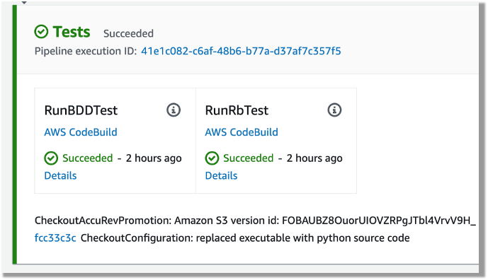
In the smoke test, the team may run both unit tests and functional tests. Ideally, these tests are better to run in parallel to speed up the pipeline. In AWS CodePipeline, we can set up a stage to run multiple steps in parallel. In our example, the pipeline runs both BDD tests and Robot Framework (RPA) tests.

The following CloudFormation code snippet runs two different tests. You use the same RunOrder value to indicate the actions run in parallel.

#...
        - Name: Tests
          Actions:
            - Name: RunBDDTest
              ActionTypeId:
                Category: Build
                Owner: AWS
                Provider: CodeBuild
                Version: 1
              Configuration:
                ProjectName: !Ref BddTestBankDemoStage
                PrimarySource: Config
              InputArtifacts:
                - Name: DemoBin
                - Name: Config
              RunOrder: 1
            - Name: RunRbTest
              ActionTypeId:
                Category: Build
                Owner: AWS
                Provider: CodeBuild
                Version: 1
              Configuration:
                ProjectName : !Ref RpaTestBankDemoStage
                PrimarySource: Config
              InputArtifacts:
                - Name: DemoBin
                - Name: Config
              RunOrder: 1  
#...

The following screenshot shows the example actions on the CodePipeline console that use the preceding code.

Screenshot of CodePipeine parallel execution tests using a same run order value

Figure – Screenshot of CodePipeine parallel execution tests

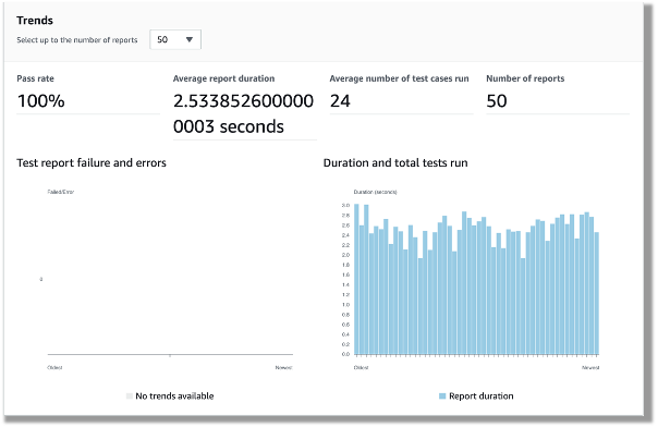
Both DBB and RPA tests produce jUnit format reports, which CodeBuild can ingest and show on the CodeBuild console. This is a great way for project management and business users to track the quality trend of an application. The following screenshot shows the CodeBuild report generated from the BDD tests.

CodeBuild report generated from the BDD tests showing 100% pass rate

Figure – CodeBuild report generated from the BDD tests

Automated regression tests

After you test the changes in the project team pipeline, you can automatically promote them to another stream with other team members’ changes for further testing. The scope of this testing stream is significantly more comprehensive, with a greater number and wider range of tests and higher volume of test data. The changes promoted to this stream by each team member are tested in this environment at the end of each day throughout the life of the project. This provides a high-quality delivery to production, with new code and changes to existing code tested together with hundreds or thousands of tests.

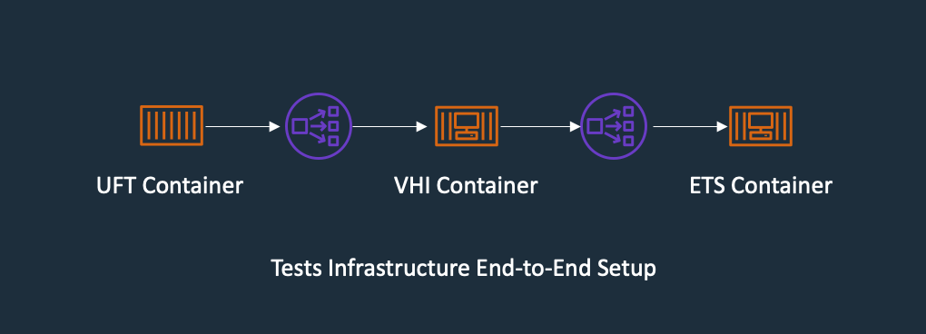
In enterprise architecture, it’s commonplace to see an application client consuming web services APIs exposed from a mainframe CICS application. One approach to do regression tests for mainframe applications is to use Micro Focus Verastream Host Integrator (VHI) to record and capture 3270 data stream processing and encapsulate these 3270 data streams as business functions, which in turn are packaged as web services. When these web services are available, they can be consumed by a test automation product, which in our environment is Micro Focus UFT One. This uses the Verastream server as the orchestration engine that translates the web service requests into 3270 data streams that integrate with the mainframe CICS application. The application is deployed in Micro Focus Enterprise Test Server.

The following diagram shows the end-to-end testing components.

Regression Test the end-to-end testing components using ECS Container for Exterprise Test Server, Verastream Host Integrator and UFT One Container, all integration points are using Elastic Network Load Balancer

Figure – Regression Test Infrastructure end-to-end Setup

To ensure we have the coverage required for large mainframe applications, we sometimes need to run thousands of tests against very large production volumes of test data. We want the tests to run faster and complete as soon as possible so we reduce AWS costs—we only pay for the infrastructure when consuming resources for the life of the test environment when provisioning and running tests.

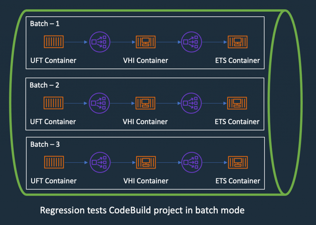
Therefore, the design of the test environment needs to scale out. The batch feature in CodeBuild allows you to run tests in batches and in parallel rather than serially. Furthermore, our solution needs to minimize interference between batches, a failure in one batch doesn’t affect another running in parallel. The following diagram depicts the high-level design, with each batch build running in its own independent infrastructure. Each infrastructure is launched as part of test preparation, and then torn down in the post-test phase.

Regression Tests in CodeBuoild Project setup to use batch mode, three batches running in independent infrastructure with containers

Figure – Regression Tests in CodeBuoild Project setup to use batch mode

Building and deploying regression test components

Following the design of the parallel regression test environment, let’s look at how we build each component and how they are deployed. The followings steps to build our regression tests use a working backward approach, starting from deployment in the Enterprise Test Server:

  1. Create a batch build in CodeBuild.
  2. Deploy to Enterprise Test Server.
  3. Deploy the VHI model.
  4. Deploy UFT One Tests.
  5. Integrate UFT One into CodeBuild and CodePipeline and test the application.

Creating a batch build in CodeBuild

We update two components to enable a batch build. First, in the CodePipeline CloudFormation resource, we set BatchEnabled to be true for the test stage. The UFT One test preparation stage uses the CloudFormation template to create the test infrastructure. The following code is an example of the AWS CloudFormation snippet with batch build enabled:

#...
        - Name: SystemsTest
          Actions:
            - Name: Uft-Tests
              ActionTypeId:
                Category: Build
                Owner: AWS
                Provider: CodeBuild
                Version: 1
              Configuration:
                ProjectName : !Ref UftTestBankDemoProject
                PrimarySource: Config
                BatchEnabled: true
                CombineArtifacts: true
              InputArtifacts:
                - Name: Config
                - Name: DemoSrc
              OutputArtifacts:
                - Name: TestReport                
              RunOrder: 1
#...

Second, in the buildspec configuration of the test stage, we provide a build matrix setting. We use the custom environment variable TEST_BATCH_NUMBER to indicate which set of tests runs in each batch. See the following code:

version: 0.2
batch:
  fast-fail: true
  build-matrix:
    static:
      ignore-failure: false
    dynamic:
      env:
        variables:
          TEST_BATCH_NUMBER:
            - 1
            - 2
            - 3 
phases:
  pre_build:
commands:
#...

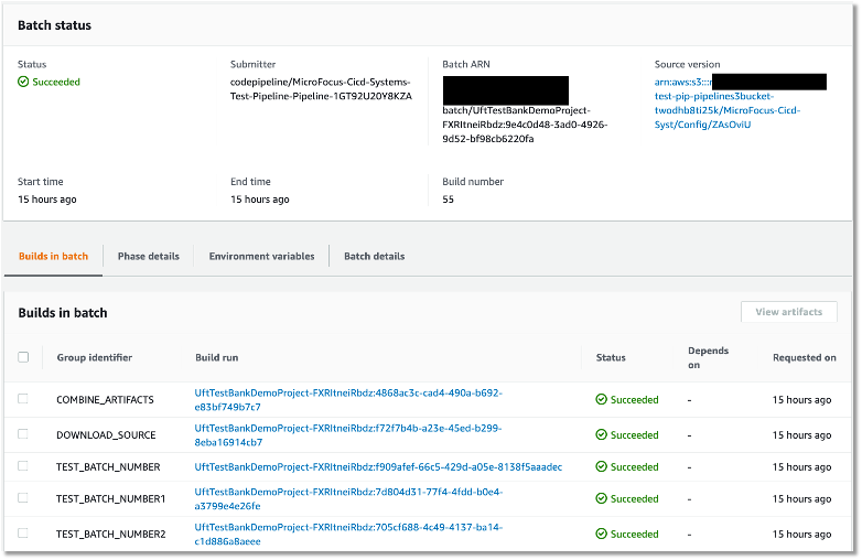
After setting up the batch build, CodeBuild creates multiple batches when the build starts. The following screenshot shows the batches on the CodeBuild console.

Regression tests Codebuild project ran in batch mode, three batches ran in prallel successfully

Figure – Regression tests Codebuild project ran in batch mode

Deploying to Enterprise Test Server

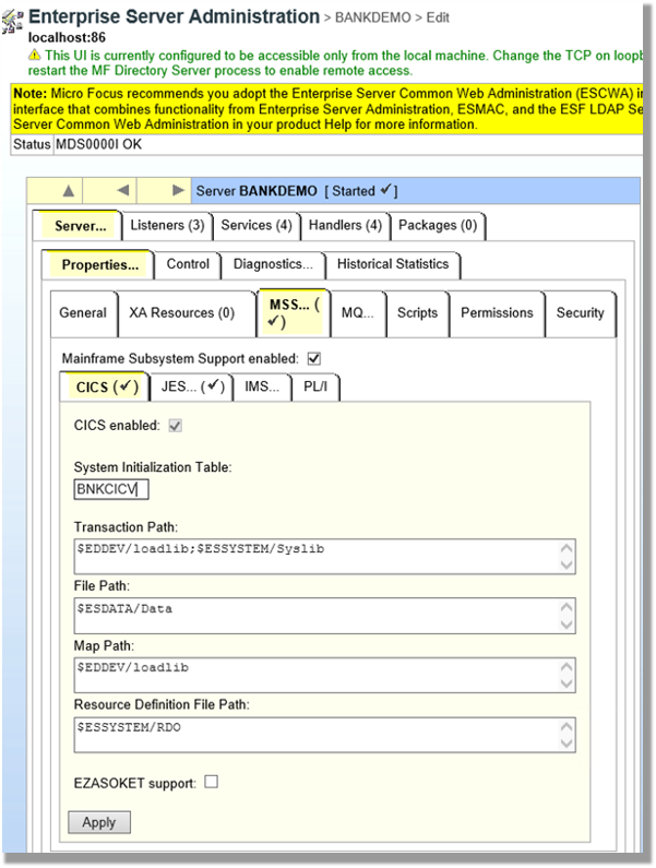
ETS is the transaction engine that processes all the online (and batch) requests that are initiated through external clients, such as 3270 terminals, web services, and websphere MQ. This engine provides support for various mainframe subsystems, such as CICS, IMS TM and JES, as well as code-level support for COBOL and PL/I. The following screenshot shows the Enterprise Test Server administration page.

Enterprise Server Administrator window showing configuration for CICS

Figure – Enterprise Server Administrator window

In this mainframe application testing use case, the regression tests are CICS transactions, initiated from 3270 requests (encapsulated in a web service). For more information about Enterprise Test Server, see the Enterprise Test Server and Micro Focus websites.

In the regression pipeline, after the stage of mainframe artifact compiling, we bake in the artifact into an ETS Docker container and upload the image to an Amazon ECR repository. This way, we have an immutable artifact for all the tests.

During each batch’s test preparation stage, a CloudFormation stack is deployed to create an Amazon ECS service on Windows EC2. The stack uses a Network Load Balancer as an integration point for the VHI’s integration.

The following code is an example of the CloudFormation snippet to create an Amazon ECS service using an Enterprise Test Server Docker image:

#...
  EtsService:
    DependsOn:
    - EtsTaskDefinition
    - EtsContainerSecurityGroup
    - EtsLoadBalancerListener
    Properties:
      Cluster: !Ref 'WindowsEcsClusterArn'
      DesiredCount: 1
      LoadBalancers:
        -
          ContainerName: !Sub "ets-${AWS::StackName}"
          ContainerPort: 9270
          TargetGroupArn: !Ref EtsPort9270TargetGroup
      HealthCheckGracePeriodSeconds: 300          
      TaskDefinition: !Ref 'EtsTaskDefinition'
    Type: "AWS::ECS::Service"

  EtsTaskDefinition:
    Properties:
      ContainerDefinitions:
        -
          Image: !Sub "${AWS::AccountId}.dkr.ecr.us-east-1.amazonaws.com/systems-test/ets:latest"
          LogConfiguration:
            LogDriver: awslogs
            Options:
              awslogs-group: !Ref 'SystemsTestLogGroup'
              awslogs-region: !Ref 'AWS::Region'
              awslogs-stream-prefix: ets
          Name: !Sub "ets-${AWS::StackName}"
          cpu: 4096
          memory: 8192
          PortMappings:
            -
              ContainerPort: 9270
          EntryPoint:
          - "powershell.exe"
          Command: 
          - '-F'
          - .\StartAndWait.ps1
          - 'bankdemo'
          - C:\bankdemo\
          - 'wait'
      Family: systems-test-ets
    Type: "AWS::ECS::TaskDefinition"
#...

Deploying the VHI model

In this architecture, the VHI is a bridge between mainframe and clients.

We use the VHI designer to capture the 3270 data streams and encapsulate the relevant data streams into a business function. We can then deliver this function as a web service that can be consumed by a test management solution, such as Micro Focus UFT One.

The following screenshot shows the setup for getCheckingDetails in VHI. Along with this procedure we can also see other procedures (eg calcCostLoan) defined that get generated as a web service. The properties associated with this procedure are available on this screen to allow for the defining of the mapping of the fields between the associated 3270 screens and exposed web service.

example of VHI designer to capture the 3270 data streams and encapsulate the relevant data streams into a business function getCheckingDetails

Figure – Setup for getCheckingDetails in VHI

The following screenshot shows the editor for this procedure and is initiated by the selection of the Procedure Editor. This screen presents the 3270 screens that are involved in the business function that will be generated as a web service.

VHI designer Procedure Editor shows the procedure

Figure – VHI designer Procedure Editor shows the procedure

After you define the required functional web services in VHI designer, the resultant model is saved and deployed into a VHI Docker image. We use this image and the associated model (from VHI designer) in the pipeline outlined in this post.

For more information about VHI, see the VHI website.

The pipeline contains two steps to deploy a VHI service. First, it installs and sets up the VHI models into a VHI Docker image, and it’s pushed into Amazon ECR. Second, a CloudFormation stack is deployed to create an Amazon ECS Fargate service, which uses the latest built Docker image. In AWS CloudFormation, the VHI ECS task definition defines an environment variable for the ETS Network Load Balancer’s DNS name. Therefore, the VHI can bootstrap and point to an ETS service. In the VHI stack, it uses a Network Load Balancer as an integration point for UFT One test integration.

The following code is an example of a ECS Task Definition CloudFormation snippet that creates a VHI service in Amazon ECS Fargate and integrates it with an ETS server:

#...
  VhiTaskDefinition:
    DependsOn:
    - EtsService
    Type: AWS::ECS::TaskDefinition
    Properties:
      Family: systems-test-vhi
      NetworkMode: awsvpc
      RequiresCompatibilities:
        - FARGATE
      ExecutionRoleArn: !Ref FargateEcsTaskExecutionRoleArn
      Cpu: 2048
      Memory: 4096
      ContainerDefinitions:
        - Cpu: 2048
          Name: !Sub "vhi-${AWS::StackName}"
          Memory: 4096
          Environment:
            - Name: esHostName 
              Value: !GetAtt EtsInternalLoadBalancer.DNSName
            - Name: esPort
              Value: 9270
          Image: !Ref "${AWS::AccountId}.dkr.ecr.us-east-1.amazonaws.com/systems-test/vhi:latest"
          PortMappings:
            - ContainerPort: 9680
          LogConfiguration:
            LogDriver: awslogs
            Options:
              awslogs-group: !Ref 'SystemsTestLogGroup'
              awslogs-region: !Ref 'AWS::Region'
              awslogs-stream-prefix: vhi

#...

Deploying UFT One Tests

UFT One is a test client that uses each of the web services created by the VHI designer to orchestrate running each of the associated business functions. Parameter data is supplied to each function, and validations are configured against the data returned. Multiple test suites are configured with different business functions with the associated data.

The following screenshot shows the test suite API_Bankdemo3, which is used in this regression test process.

the screenshot shows the test suite API_Bankdemo3 in UFT One test setup console, the API setup for getCheckingDetails

Figure – API_Bankdemo3 in UFT One Test Editor Console

For more information, see the UFT One website.

Integrating UFT One and testing the application

The last step is to integrate UFT One into CodeBuild and CodePipeline to test our mainframe application. First, we set up CodeBuild to use a UFT One container. The Docker image is available in Docker Hub. Then we author our buildspec. The buildspec has the following three phrases:

  • Setting up a UFT One license and deploying the test infrastructure
  • Starting the UFT One test suite to run regression tests
  • Tearing down the test infrastructure after tests are complete

The following code is an example of a buildspec snippet in the pre_build stage. The snippet shows the command to activate the UFT One license:

version: 0.2
batch: 
# . . .
phases:
  pre_build:
    commands:
      - |
        # Activate License
        $process = Start-Process -NoNewWindow -RedirectStandardOutput LicenseInstall.log -Wait -File 'C:\Program Files (x86)\Micro Focus\Unified Functional Testing\bin\HP.UFT.LicenseInstall.exe' -ArgumentList @('concurrent', 10600, 1, ${env:AUTOPASS_LICENSE_SERVER})        
        Get-Content -Path LicenseInstall.log
        if (Select-String -Path LicenseInstall.log -Pattern 'The installation was successful.' -Quiet) {
          Write-Host 'Licensed Successfully'
        } else {
          Write-Host 'License Failed'
          exit 1
        }
#...

The following command in the buildspec deploys the test infrastructure using the AWS Command Line Interface (AWS CLI)

aws cloudformation deploy --stack-name $stack_name `
--template-file cicd-pipeline/systems-test-pipeline/systems-test-service.yaml `
--parameter-overrides EcsCluster=$cluster_arn `
--capabilities CAPABILITY_IAM

Because ETS and VHI are both deployed with a load balancer, the build detects when the load balancers become healthy before starting the tests. The following AWS CLI commands detect the load balancer’s target group health:

$vhi_health_state = (aws elbv2 describe-target-health --target-group-arn $vhi_target_group_arn --query 'TargetHealthDescriptions[0].TargetHealth.State' --output text)
$ets_health_state = (aws elbv2 describe-target-health --target-group-arn $ets_target_group_arn --query 'TargetHealthDescriptions[0].TargetHealth.State' --output text)          

When the targets are healthy, the build moves into the build stage, and it uses the UFT One command line to start the tests. See the following code:

$process = Start-Process -Wait  -NoNewWindow -RedirectStandardOutput UFTBatchRunnerCMD.log `
-FilePath "C:\Program Files (x86)\Micro Focus\Unified Functional Testing\bin\UFTBatchRunnerCMD.exe" `
-ArgumentList @("-source", "${env:CODEBUILD_SRC_DIR_DemoSrc}\bankdemo\tests\API_Bankdemo\API_Bankdemo${env:TEST_BATCH_NUMBER}")

The next release of Micro Focus UFT One (November or December 2020) will provide an exit status to indicate a test’s success or failure.

When the tests are complete, the post_build stage tears down the test infrastructure. The following AWS CLI command tears down the CloudFormation stack:


#...
	post_build:
	  finally:
	  	- |
		  Write-Host "Clean up ETS, VHI Stack"
		  #...
		  aws cloudformation delete-stack --stack-name $stack_name
          aws cloudformation wait stack-delete-complete --stack-name $stack_name

At the end of the build, the buildspec is set up to upload UFT One test reports as an artifact into Amazon Simple Storage Service (Amazon S3). The following screenshot is the example of a test report in HTML format generated by UFT One in CodeBuild and CodePipeline.

UFT One HTML report shows regression testresult and test detals

Figure – UFT One HTML report

A new release of Micro Focus UFT One will provide test report formats supported by CodeBuild test report groups.

Conclusion

In this post, we introduced the solution to use Micro Focus Enterprise Suite, Micro Focus UFT One, Micro Focus VHI, AWS developer tools, and Amazon ECS containers to automate provisioning and running mainframe application tests in AWS at scale.

The on-demand model allows you to create the same test capacity infrastructure in minutes at a fraction of your current on-premises mainframe cost. It also significantly increases your testing and delivery capacity to increase quality and reduce production downtime.

A demo of the solution is available in AWS Partner Micro Focus website AWS Mainframe CI/CD Enterprise Solution. If you’re interested in modernizing your mainframe applications, please visit Micro Focus and contact AWS mainframe business development at [email protected].

References

Micro Focus


Peter Woods

Peter Woods

Peter has been with Micro Focus for almost 30 years, in a variety of roles and geographies including Technical Support, Channel Sales, Product Management, Strategic Alliances Management and Pre-Sales, primarily based in Europe but for the last four years in Australia and New Zealand. In his current role as Pre-Sales Manager, Peter is charged with driving and supporting sales activity within the Application Modernization and Connectivity team, based in Melbourne.

Leo Ervin

Leo Ervin

Leo Ervin is a Senior Solutions Architect working with Micro Focus Enterprise Solutions working with the ANZ team. After completing a Mathematics degree Leo started as a PL/1 programming with a local insurance company. The next step in Leo’s career involved consulting work in PL/1 and COBOL before he joined a start-up company as a technical director and partner. This company became the first distributor of Micro Focus software in the ANZ region in 1986. Leo’s involvement with Micro Focus technology has continued from this distributorship through to today with his current focus on cloud strategies for both DevOps and re-platform implementations.

Kevin Yung

Kevin Yung

Kevin is a Senior Modernization Architect in AWS Professional Services Global Mainframe and Midrange Modernization (GM3) team. Kevin currently is focusing on leading and delivering mainframe and midrange applications modernization for large enterprise customers.