In November 2021, we launched Amazon EC2 M6a instances, powered by 3rd Gen AMD EPYC (Milan) processors, running at frequencies up to 3.6 GHz, which offer you up to 35 percent improvement in price performance compared to M5a instances. Many customers who run workloads that are dependent on x86 instructions, such as SAP, are looking for ways to optimize their cloud utilization. They’re taking advantage of the compute choice that EC2 offers.
Today, we’re announcing the general availability of new, general purpose Amazon EC2 M7a instances, powered by the 4th Gen AMD EPYC (Genoa) processors with a maximum frequency of 3.7 GHz, which offer up to 50 percent higher performance compared to M6a instances. This increased performance gives you the ability to process data faster, consolidate workloads, and lower the cost of ownership.
M7a instances support AVX-512, Vector Neural Network Instructions (VNNI) and brain floating point (bfloat16). These instances feature Double Data Rate 5 (DDR5) memory, which enable high-speed access to data in-memory, and deliver 2.25 times more memory bandwidth compared to M6a instances for lower latency.
M7a instances are SAP-certified and ideal for applications that benefit from high performance and high throughput, such as financial applications, application servers, simulation modeling, gaming, mid-size data stores, application development environments, and caching fleets.
M7a instances feature sizes of up to 192 vCPUs with 768 GiB RAM. Here are the detailed specs:
Name
vCPUs
Memory (GiB)
Network Bandwidth (Gbps)
EBS Bandwidth (Gbps)
m7a.medium
1
4
Up to 12.5
Up to 10
m7a.large
2
8
Up to 12.5
Up to 10
m7a.xlarge
4
16
Up to 12.5
Up to 10
m7a.2xlarge
8
32
Up to 12.5
Up to 10
m7a.4xlarge
16
64
Up to 12.5
Up to 10
m7a.8xlarge
32
128
12.5
10
m7a.12xlarge
48
192
18.75
15
m7a.16xlarge
64
256
25
20
m7a.24xlarge
96
384
37.5
30
m7a.32xlarge
128
512
50
40
m7a.48xlarge
192
768
50
40
m7a.metal-48xl
192
768
50
40
M7a instances have up to 50 Gbps enhanced networking and 40 Gbps EBS bandwidth, which is similar to M6a instances. But you have a new medium instance size, which enables you to right-size your workloads more accurately, offering 1 vCPUs, 4 GiB, and the largest size offering 192 vCPUs, 768 GiB.
The new instances are built on the AWS Nitro System, a collection of building blocks that offloads many of the traditional virtualization functions to dedicated hardware for high performance, high availability, and highly secure cloud instances.
Now Available Amazon EC2 M7a instances are now available today in AWS Regions: US East (Ohio), US East (N. Virginia), US West (Oregon), and EU (Ireland). As usual with Amazon EC2, you only pay for what you use. For more information, see the Amazon EC2 pricing page.
“Subinterpreters”, which are separate Python interpreters running in the
same process that can be
created using
the C API, have been a part of Python since the previous century
(version 1.5 in 1997), but they are largely unknown and unused.
Eric Snow has been on something of a quest, since 2015 or so, to bring better multicore processing to Python by
way of subinterpreters (or “multiple interpreters”). He has made it part
of the way there, with the
adoption of a separate global interpreter lock (GIL) for each
subinterpreter, which
was added for Python 3.12. Back in April, Snow gave a talk (YouTube video) at
PyCon about multiple interpreters, their status, and his plans for the
feature in
the future.
Updated 10/31/2024 to include additional Brand Registration steps for “Public Profit” companies
What is 10DLC?
Ten-Digit Long Code, or more commonly shortened as 10DLC, is intended specifically for sending Application-to-Person (A2P) SMS in the United States only. If you don’t send text messages to recipients in the US, then 10DLC doesn’t apply to you. 10DLC was designed to cover the volume and throughput middle ground between toll-free numbers on the low end and short codes on the high end. All senders using 10DLC are required to register both their company and their campaign(s), which is managed by a third-party company called The Campaign Registry (TCR). TCR maintains an industry-wide database of companies and use cases that are authorized to send messages, to US registered handsets, using 10DLC phone numbers.
How to Register for 10DLC
Registration can be done within the AWS console as well as programmatic registration via the SMS V2 API.
If you have not already registered a company then select registration type “US 10DLC brand registration” as the Registration type and give it a “Registration friendly name” you will recognize later and proceed with the best practices below.
To help ensure your registration is approved during this vetting process follow these best practices when registering.
Who Should Register for a 10DLC?
The information provided during registration should be for the company from whom SMS messages will be sent from.
Examples:
Example 1: Company X wants to send their customers alerts via SMS should their account be compromised and there is a need to reset passwords.
In this example the company being registered is Company X.
Example 2: Company Y is an Independent Software Vendor(ISV) with 100s of their customers using their software platform. Company Z wants to give their customers the ability to send SMS from within their platform.
In this example each of Company Y’s customers who want to send SMS will need to provide their information. Each of these customers will need their own separate 10DLC for each use case that Company Y wants to enable for their customers.
Company Y should define very clearly for their customers the types of messages that can be sent as each of their customers will be expected to send only messages that align with the Campaign(Use-Case) that they register for.
Example 3: Company Z is an Independent Software Vendor(ISV) with 100s of their customers using their software platform. Company Z wants to provide One-Time Password(OTP) codes via SMS.
In this example the company being registered will be Company Z.
10DLC Registration Best Practices
As you progress through the steps of 10DLC registration follow these best practices to ensure a smooth process. Begin here if you have not registered your company(ies) yet.
Company Registration Info and Additional Company and Contact Info
Best practices for Company Registration and Additional Company and Contact Info
Make sure to enter all information correctly.
Dependent on the country in which you have a Tax ID, enter into the Tax ID field one of the following:
US=EIN
CA=BN
Other=VAT
If you select “PUBLIC_PROFIT” as your “Legal form of organization” you MUST fill out the following fields and complete the external brand verification shown in the screenshots below in the section titled “Public Profit Brand Verification Email Process”
Make sure to complete:
Stock symbol
Stock exchange
Brand verification email – Make sure to provide your personal company email. You will receive an email from [email protected] to complete the brand verification.
Select the vertical that most closely aligns with your business
Make sure that your website is publicly accessible. Your registration will be denied if the reviewer cannot access the site.
It is a hard requirement to have both a support email and phone number
Make sure your support email and support phone number are both active
Make sure that your Company name and Email/Website domains match
If you register the company Amazon Inc. but then list a support email of [email protected] your registration will likely be rejected if you are considered a large enough brand that should have a dedicated email domain.
Public Profit Brand Verification Email Process – Required if you selected “PUBLIC_PROFIT” as your “Legal form of organization”
Once you submit your Brand Registration you will receive an email from [email protected] to complete the brand verification. This may take 1-3 days to arrive.
Step 1: Example email you will receive below
Step 2: Form to fill out from link in email
Step 3: Brand verification complete
Once you have completed and submitted your registration, as soon as you see your Brand Registration Status show as “Complete” you are ready to move on to “Brand Vetting.” Read “Additional Company Vetting for Potential Increased Quotas” below for next steps.
Additional Company Vetting for Potential Increased Quotas
Once you have completed the initial Company registration you have the following quotas assigned to your business:
AT&T: 1.25 Messages Per Second(MPS) or 75 Transactions Per Minute(TPM)
T-Mobile = 2000 messages/day
The quotas above do not mean that you cannot message recipients who use other carriers, these are just limits that these carriers have published. If the throughput above isn’t enough for your business’s needs you can apply for US 10DLC brand vetting, for a $40 fee.
Click the “Create Registration” button again and select “US 10DLC brand vetting” as the “Registration type.”
Select the radio button for the brand you previously registered. This vetting will be applied to that brand.
If you have multiple brands you will need to do this for each of them
The Campaign Registry, a third-party provider, will then do a deeper vetting of the information you have already provided and will give your company a score that will determine the throughput and volume apportioned to you. Read here for a detailed breakdown of the possible scores and the quotas that are attached to them. Note: Vetting doesn’t guarantee that your carrier throughput or daily volume will increase. It is possible for the vetting results to decrease carrier throughput and daily volume.
Provide a clear and comprehensive overview of the campaign’s objectives and interactions the end-user would experience after opting in. Make sure to identify who the sender is, who the recipient is, and why messages are being sent to the intended recipient.
Example: One-Time Password messages are sent by Company X to its customers for purposes of authentication to log into our application.
Opt-In Workflow
The primary purpose of the Opt-in workflow is to demonstrate that the end user explicitly consents to receive text messages and understands the nature of the program. Your application is being reviewed by a 3rd party reviewer so make sure to provide clear and thorough information about how your end-users opt-in to your SMS service and any associated fees or charges. If the reviewer cannot determine how your opt-in process works then your application will be denied and returned.
Note: If you have a use case that is internal to your business, you are still required to demonstrate explicit opt-in consent from the recipients. There are no exceptions to having an opt-in workflow.
The Opt-in workflow ideally is accessible by a 3rd party reviewer. If your Opt-in process requires a log-in, is not yet published publicly, is a verbal opt-in, or if it occurs on printed sources such as fliers and paper forms then make sure to thoroughly document how this process is completed by the end-user receiving messages. Provide a screenshot of the Call to Action in such cases. Host the screen shot on a publicly accessible website (like OneDrive or Google Drive) and provide the URL
The description has to be a minimum of 40 characters
The Opt-in location must include the following:
Program (brand) name
Link to a publicly accessible Terms & Conditions page
Link to a publicly accessible Privacy Policy page
Message frequency disclosure.
Customer care contact information
Opt-out information
“Message and data rates may apply” disclosure.
Opt-in keyword
This is optional but if you plan on allowing for opt-in by texting into your originator you should indicate that keyword here
Opt-in confirmation message
Provide the exact message that will be sent back to your end-users letting them know that they have successfully registered
Example
“Welcome to AnyCo! Reply “YES” to confirm your subscription and get special offers once a month. Msg & data rates may apply. Text ‘STOP’ to opt out.”
Make sure to include:
Brand Name
It is best practice to do a “double opt-in” as seen in the example where the recipient will text back “YES” to confirm that they did want to register.
Include “Msg & data rates may apply” as seen in the example
Include opt-out language as seen in the example
Help Message
The “Help message” is the response that is required to be sent to end-users when they text the keyword “HELP” (or similar keywords). The purpose is to provide information to the end-user related to how they can get support or opt-out of the messaging program.
The message has to be a minimum of 20 characters and a maximum of 160 characters
The message must include:
Program (brand) name OR product description.
Additional customer care contact information.
It is mandatory to include a phone number and/or email for end-user support
The following is an example of a HELP response that complies with the requirements of the US mobile carriers:
ExampleCorp Account Alerts: For help call 1-888-555-0142 or go to example.com. Msg&data rates may apply. Text STOP to cancel.
Stop Message
The “Stop message” is the response that is required to be sent to end-users when they text the keyword “STOP” (or similar keywords). End-users are required to be opted out of further messages when they text the STOP (or equivalent) keyword to your number and confirms with them that they will no longer receive messages for the program.
The message has to be a minimum of 20 characters and a maximum of 160 characters
The message must include:
Program (brand) name OR product description
Confirmation that no further messages will be delivered
The following is an example of a compliant STOP response:
You are unsubscribed from ExampleCorp Account Alerts. No more messages will be sent. Reply HELP for help or call 1-888-555-0142.
Campaign Capabilities
Number capability: Choose whether or not the numbers you associate to an approved campaign can support voice outbound calling in addition to SMS. If you only require SMS you can leave the default selection of SMS-only. If you require voice calling, you should select voice as well. Selecting voice will increase the registration processing time.
Message Type: The content of your messages need to align with the Campaign Type and Message Type that you select here — if it’s misaligned your registration will be denied. You can’t change the message type on a campaign after it’s in an approved state.
Campaign Use Case
End User Messaging supports all of the standard use cases available to be sent via 10DLC and a single Special use case for communications from a non-religious registered 501(c)(3) charity aimed at providing help and raising money for those in need. For a more detailed listing of the campaign use cases supported visit this page.
Best Practices for Campaign Use Case
Select the Use case that most closely aligns to your use case.
All of the information that you provide during this process needs to align with this selection or your registration will be rejected
Make sure to ONLY select a Sub use case if you select a use case of MIXED or LOW_VOLUME
Note: The “Low Volume” and “Mixed” campaigns have lower quotas which are the same as a company that does not opt for the increased vetting detailed above:
AT&T: 1.25 Messages Per Second(MPS) or 75 Transactions Per Minute(TPM)
T-Mobile = 2000 messages/day
For each of the Yes/No drop down selections make sure to be truthful. These registrations are being done by humans who will be checking each of these. An untruthful answer can cause your registration to be rejected.
If you plan on using links within your messages remember that generic URL shorteners e.g. “bit.ly/LONGLINK” will be rejected. If you would like to use shorteners make sure that it is a branded shortener such as “any.co/LONGLINK”
Subscriber opt-in
Subscriber opt-in is automatically set to “Yes” on your behalf. Explicit opt-in is required of all end-users regardless of your use case.
Carriers require that your SMS numbers reply to the ‘HELP’ keyword or similar at all times regardless of the numbers opt-in status. More information related to HELP auto-response requirements can be found in End User Messaging best practices documentation here
Direct Lending or Loan Arrangement
If you are a 1st party lender you can get approval for transactional use cases (loan transaction receipts, OTPs, etc.). If your company is related to the lending business then you must mark this as “yes“
Embedded Link
If you have supplied messaging examples with an embedded link you must mark this as a “yes.” If this is misaligned with your content then your registration will be rejected
Note: Generic link shorteners such as Bitly or TinyURL should not be used and may cause your registration to be rejected. Make sure that any links in your sample messages are branded and consistent with your domain
Embedded Phone Number
If you have supplied messaging examples with an embedded phone number you must mark this as a “yes.” If this is misaligned with your content then your registration will be rejected
Age-Gated Content
There is a potential to be rejected or for the campaign to be suspended later if your content includes age gated material and you do not mark “yes” here
If they are do they need to do anything different here?
Message Samples
Sample messages should reflect actual messages to be sent under the campaign you are registering for. It is critical to ensure that there is consistency between the use case, your campaign description, and the content of the messages.
Best Practices for Sample Messages
Sample messages should reflect actual messages to be sent under campaign
Indicate any templated fields that are variable with brackets and make sure to be clear with what information may be replaced
Example: Hi, [FirstName] this is Amazon inc. letting you know that your delivery is ready
Each sample message has to be a minimum of 20 characters. If you plan to use multiple message templates for this 10DLC campaign, include them as well
Sample messages should identify who is sending the message (brand name)
Ensure that at least one sample message includes your business name
Include opt-out language to at least 1 sample message
Example: You are unsubscribed from ExampleCorp Account Alerts. No more messages will be sent. Reply HELP for help or call 1-888-555-0142.
Make sure your messaging does not involve prohibited content such as cannabis, hate speech, etc. and that your use case is compliant with AWS Messaging Policy
What to do if your 10DLC campaigns are rejected
If your Company registration or Campaign registration is rejected please follow the steps here to create a case and the AWS Support team will provide information about the reasons that your 10DLC campaign registration was rejected in your AWS Support case.
This blog post is written by Brian Graf, Senior Developer Advocate, Amazon Lightsail and Sophia Parafina, Senior Developer Advocate.
Amazon Lightsail is a virtual private server (VPS) for deploying both operating systems (OS) and pre-packaged applications, such as WordPress, Plesk, cPanel, PrestaShop, and more. When deploying these instances, you can run launch scripts with additional commands such as installation of applications, configuration of system files, or installing pre-requisites for your application.
Where do I add a launch script?
If you’re deploying an instance with the Lightsail console, launch scripts can be added to an instance at deployment. They are added in the ‘deploy instance’ page:
The launch script must be added before the instance is deployed, because launch scripts can’t retroactively run after deployment.
Anatomy of a Windows Launch Script
When deploying a Lightsail Windows instance, you can use a batch script or a PowerShell script in the ‘launch script’ textbox. Of the two options, PowerShell is more extensible and provides greater flexibility for configuration and control.
If you choose to write your launch script as a batch file, you must add <script> </script> tags at the beginning and end of your code respectively. Alternatively, a launch script in PowerShell, must use the <powershell></powershell> tags in a similar fashion.
After the closing </script> or </powershell> tag, you must add a <persist></persist> tag on the following line. The persist tag is used to determine if this is a run-once command or if it should run every time your instance is rebooted or changed from the ‘Stop’ to ‘Start’ state. If you want your script to run every time the instance is rebooted or started, then you must set the persist tag to ‘true’. If you want your launch script to just run once, then you would set your persist tag to ‘false’.
Anatomy of a Linux Launch Script
Like a Windows launch script, a Linux launch script requires specific code on the first row of the textbox to successfully execute during deployment. You must place ‘#!/bin/bash’ as the first line of code to set the shell that executes the rest of the script. After first line of code, you can continue adding additional commands to achieve the results you want.
How do I know if my Launch Script ran successfully?
Although running launch scripts is convenient to create a baseline instance, it’s possible that your instance doesn’t achieve the desired end-state because of an error in your script or permissions issues. You must troubleshoot to see why the launch script didn’t complete successfully. To find if the launch script ran successfully, refer to the instance logs to determine whether your launch script was successful or not.
For Windows, the launch log can be found in: C:\ProgramData\Amazon\EC2-Windows\launch\Log\UserdataExecution.log. Note that ProgramData is a hidden folder, and unless you access the file from PowerShell or Command Prompt, you must use Windows File Explorer (`View > Show > Hidden items`) folders to see it.
For Linux, the launch log can be found in: /var/log/cloud-init-output.log and can be monitored after your instance launches by tailing the log by typing the following in the terminal:
tail -f /var/log/cloud-init-output.log
If you want to see the entire log file including commands that have already run before you opened the log file, then you can type the following in the terminal:
less +F /var/log/cloud-init-output.log
On a Windows instance, an easy way to monitor the UserdataExecution.log is to add the following code in your launch script, which creates a shortcut to tail or watch the log as commands are executing:
# Create a log-monitoring script to monitor the progress of the launch script execution

$monitorlogs = @"
get-content C:\ProgramData\Amazon\EC2-Windows\launch\Log\UserdataExecution.log -wait
"@

# Save the log-monitoring script to the desktop for the user

$monitorlogs | out-file -FilePath C:\Users\Administrator\Desktop\MonitorLogs.ps1 -Encoding utf8 -Force

</powershell>
<persist>false</persist>
If the script was executed, then the last line of the log should say ‘{Timestamp}: User data script completed’.
However, if you want more detail, you can build the logging into your launch script. For example, you can append a text or log file with each command so that you can read the output in an easy-to-access location:
<powershell>
# Set the location for the log file. In this case,
# it will appear on the desktop of your Lightsail instance
$loc = "c:\Users\Administrator\Desktop\mylog.txt"

# Write text to the log file
Write-Output "Starting Script" >> $loc

# Download and install Chocolatey to do unattended installations of the rest of the apps.
iex ((New-Object System.Net.WebClient).DownloadString('https://chocolatey.org/install.ps1'))

# You could run commands like this to output the progress to the log file:

# Install vscode and all dependencies
choco install -y vscode --force --force-dependencies --verbose >> $loc

# Install git and all dependencies
choco install -y git --force --force-dependencies --verbose >> $loc

# Completed
Write-Output "Completed" >> $loc
</powershell>
<persist>false</persist>
This code creates a log file, outputs data, and appends it along the way. If there is an issue, then you can see where the logs stopped or errors appeared.
For Ubuntu and Amazon Linux 2
If the cloud-init-output.log isn’t comprehensive enough, then you can re-direct the output from your commands to a log file of your choice. In this example, we create a log file in the /tmp/ directory and push all output from our commands to this file.
# Create the log file
touch /tmp/launchscript.log

# Add text to the log file if you so choose
echo 'Starting' >> /tmp/launchscript.log

# Update package index
sudo apt update >> /tmp/launchscript.log

# Install software to manage independent software vendor sources
sudo apt -y install software-properties-common >> /tmp/launchscript.log

# Add the repository for all PHP versions
sudo add-apt-repository -y ppa:ondrej/php >> /tmp/launchscript.log

# Install Web server, mySQL client, PHP (and packages), unzip, and curl
sudo apt -y install apache2 mysql-client-core-8.0 php8.0 libapache2-mod-php8.0 php8.0-common php8.0-imap php8.0-mbstring php8.0-xmlrpc php8.0-soap php8.0-gd php8.0-xml php8.0-intl php8.0-mysql php8.0-cli php8.0-bcmath php8.0-ldap php8.0-zip php8.0-curl unzip curl >> /tmp/launchscript.log

# Any final text you want to include
echo 'Completed' >> /tmp/launchscript.log
It’s possible to check the logs before the launch script has finished executing. One way to follow along is to ‘tail’ the log file. This lets you stream all updates as they occur. You can monitor the log using:
‘tail -f /tmp/launchscript.log’. </code>
Using Launch Scripts from AWS Command Line Interface (AWS CLI)
You can deploy their Lightsail instances from the AWS Command Line Interface (AWS CLI) instead of the Lightsail console. You can add launch scripts to the AWS CLI command as a parameter by creating a variable with the script and referencing the variable, or by saving the launch script as a file and referencing the local file location on your computer.
The launch script is still written the same way as the previous examples. For a Windows instance with a PowerShell launch script, you can deploy a Lightsail instance with a launch script with the following code:
# PowerShell script saved in the Downloads folder:

$loc = "c:\Users\Administrator\Desktop\mylog.txt"

# Write text to the log file

Write-Output "Starting Script" >> $loc

# Download and install Chocolatey to do unattended installations of the rest of the apps.

iex ((New-Object System.Net.WebClient).DownloadString('https://chocolatey.org/install.ps1'))

# You could run commands like this to output the progress to the log file:

# Install vscode and all dependencies

choco install -y vscode --force --force-dependencies --verbose >> $loc

# Install git and all dependencies

choco install -y git --force --force-dependencies --verbose >> $loc

# Completed

Write-Output "Completed" >> $loc
AWS CLI code to deploy a Windows Server 2019 medium instance in the us-west-2a Availability Zone:
Remember to delete resources when you are finished using them to avoid incurring future costs.
Conclusion
You now have the understanding and examples of how to create and troubleshoot Lightsail launch scripts both through the Lightsail console and AWS CLI. As demonstrated in this blog, using launch scripts, you can increase your productivity and decrease the deployment time and configuration of your applications. For more examples of using launch scripts, check out the aws-samples GitHub repository. You now have all the foundational building blocks you need to successfully script automated instance configuration. To learn more about Lightsail, visit the Lightsail service page.
Version
5.0 (“Daedalus”) of the Debian-based Devuan distribution has been
released. “This is the result of many months of painstaking work by the
Team and detailed testing by the wider Devuan community.” The
announcement lists a couple of new features but mostly defers to the
Debian 12 (“bookworm”) release notes.
As customers accelerate their migrations to the cloud and transform their businesses, some find themselves in situations where they have to manage data analytics in a multi-cloud environment, such as acquiring a company that runs on a different cloud provider. Customers who use multi-cloud environments often face challenges in data access and compatibility that can create blockades and slow down productivity.
When managing multi-cloud environments, customers must look for services that address these gaps through features providing interoperability across clouds. With the release of the Amazon Athena data source connector for Google Cloud Storage (GCS), you can run queries within AWS to query data in Google Cloud Storage, which can be stored in relational, non-relational, object, and custom data sources, whether that be Parquet or comma-separated value (CSV) format. Athena provides the connectivity and query interface and can easily be plugged into other AWS services for downstream use cases such as interactive analysis and visualizations. Some examples include AWS data analytics services such as AWS Glue for data integration, Amazon QuickSight for business intelligence (BI), as well as third-party software and services from AWS Marketplace.
This post demonstrates how to use Athena to run queries on Parquet or CSV files in a GCS bucket.
Solution overview
The following diagram illustrates the solution architecture.
The Athena Google Cloud Storage connector uses both AWS and Google Cloud Platform (GCP), so we will be referencing both cloud providers in the architecture diagram.
We use the following AWS services in this solution:
Amazon Athena – A serverless interactive analytics service. We use Athena to run queries on data stored on Google Cloud Storage.
AWS Lambda – A serverless compute service that is event driven and manages the underlying resources for you. We deploy a Lambda function data source connector to connect AWS with Google Cloud Provider.
AWS Secrets Manager – A secrets management service that helps protect access to your applications and services. We reference the secret in Secrets Manager in the Lambda function so we can run a query on AWS and it can access the data stored on Google Cloud Provider.
AWS Glue – A serverless data analytics service for data discovery, preparation, and integration. We create an AWS Glue database and table to point to the correct bucket and files within Google Cloud Storage.
Amazon Simple Storage Service (Amazon S3) – An object storage service that stores data as objects within buckets. We create an S3 bucket to store data that exceeds the Lambda function’s response size limits.
The Google Cloud Platform portion of the architecture contains a few services as well:
Google Cloud Storage – A managed service for storing unstructured data. We use Google Cloud Storage to store data within a bucket that will be used in a query from Athena, and we upload a CSV file directly to the GCS bucket.
Google Cloud Identity and Access Management (IAM) – The central source to control and manage visibility for cloud resources. We use Google Cloud IAM to create a service account and generate a key that will allow AWS to access GCP. We create a key with the service account, which is uploaded to Secrets Manager.
Prerequisites
For this post, we create a VPC and security group that will be used in conjunction with the GCP connector. For complete steps, refer to Creating a VPC for a data source connector. The first step is to create the VPC using Amazon Virtual Private Cloud (Amazon VPC), as shown in the following screenshot.
Then we create a security group for the VPC, as shown in the following screenshot.
To begin, you must have either CSV or Parquet files stored within a GCS bucket. To create the bucket, refer to Create buckets. Make sure to note the bucket name—it will be referenced in a later step. After you create the bucket, upload your objects to the bucket. For instructions, refer to Upload objects from a filesystem.
The CSV data used in this example came from Mockaroo, which generated random test data as shown in the following screenshot. In this example, we use a CSV file, but you can also use Parquet files.
Additionally, you must create a service account to generate a key pair within Google Cloud IAM, which will be uploaded to Secrets Manager. For full instructions, refer to Create service accounts.
Now that you have a GCS bucket with a CSV file and a generated JSON key file from Google Cloud Platform, you can proceed with the rest of the steps on AWS.
On the Secrets Manager console, choose Secrets in the navigation pane.
Choose Store a new secret and specify Other type of secret.
Provide the GCP generated key file content.
The next step is to deploy the Athena Google Cloud Storage connector. For more information, refer to Using the Athena console.
On the Athena console, add a new data source.
Select Google Cloud Storage.
For Data source name, enter a name.
For Lambda function, choose Create Lambda function to be redirected to the Lambda console.
In the Application settings section, enter the information for Application name, SpillBucket, GCSSecretName, and LambdaFunctionName.
You also have to create an S3 bucket to reference the S3 spill bucket parameter in order to store data that exceeds the Lambda function’s response size limits. For more information, refer to Create your first S3 bucket.
After you provide the Lambda function’s application settings, you’re redirected to the Review and create page.
Confirm that these are the correct fields and choose Create data source.
Now that the data source connector has been created, you can connect Athena to the data source.
On the Athena console, navigate to the data source.
Under Data source details, choose the link for the Lambda function.
You can reference the Lambda function to connect to the data source. As an optional step and for validation, the variables that were put into the Lambda function can be found within the Lambda function’s environment variables on the Configuration tab.
Because the built-in GCS connector schema inference capability is limited, it’s recommended to create an AWS Glue database and table for your metadata. For instructions, refer to Setting up databases and tables in AWS Glue.
The following screenshot shows our database details.
The following screenshot shows our table details.
Query the data
Now you can run queries on Athena that will access the data stored on Google Cloud Storage.
On the Athena console, choose the correct data source, database, and table within the query editor.
RunSELECT * FROM [AWS Glue Database name].[AWS Glue Table name]in the query editor.
As shown in the following screenshot, the results will be from the bucket on Google Cloud Storage.
The data that is stored on Google Cloud Platform can be accessed through AWS and used for many use cases, such as performing business intelligence, machine learning, or data science. Doing so can help unblock developers and data scientists so they can efficiently provide results and save time.
Clean up
Complete the following steps to clean up your resources:
Delete the provisioned bucket in Google Cloud Storage.
Delete the service account under IAM & Admin.
Delete the secret GCP credentials in Secrets Manager.
Delete the S3 spill bucket.
Delete the Athena connector Lambda function.
Delete the AWS Glue database and table.
Troubleshooting
If you receive a ROLLBACK_COMPLETE state and “can not be updated error” when creating the data source in Lambda, go to AWS CloudFormation, delete the CloudFormation stack, and try recreating it.
If the AWS Glue table doesn’t appear in the Athena query editor, verify that the data source and database values are correctly selected in the Data pane on the Athena query editor console.
Conclusion
In this post, we saw how you can minimize the time and effort required to access data on Google Cloud Platform and use it efficiently on AWS. Using the data connector helps organizations become multi-cloud agnostic and helps accelerate business growth. Additionally, you can build out BI applications with the discoveries, relationships, and insights found when analyzing the data, which can further your organization’s data analysis process.
About the Author
Jonathan Wong is a Solutions Architect at AWS assisting with initiatives within Strategic Accounts. He is passionate about solving customer challenges and has been exploring emerging technologies to accelerate innovation.
Backblaze is happy to announce that Chris Opat has joined our team as senior vice president of cloud operations. Chris will oversee the strategy and operations of the Backblaze global cloud storage platform.
What Chris Brings to Backblaze
Chris expands the company’s leadership by bringing his impressive cloud and infrastructure knowledge with more than 25 years of industry experience.
Previously, Chris served as senior vice president leading platform engineering and operations at StackPath, a specialized provider in edge technology and content delivery. He also held leadership roles at CyrusOne, CompuCom, Cloudreach, and Bear Stearns/JPMorgan. Chris earned his Bachelor of Science degree in television and digital media production from Ithaca College.
Backblaze CEO, Gleb Budman, shared that Chris is a forward-thinking cloud leader with a proven track record of leading teams that are clever and bold in solving problems and creating best-in-class experiences for customers. His expertise and approach will be pivotal as more customers move to an open cloud ecosystem and will help advance Backblaze’s cloud strategy as we continue to grow.
Chris’ Role as SVP of Cloud Operations
As SVP of Cloud Operations, Chris oversees cloud strategy, platform engineering, and technology infrastructure, enabling Backblaze to further scale capacity and improve performance to meet larger-sized customers’ needs, as we continue to see success in moving up-market.
Chris says of his new role at Backblaze:
Backblaze’s vision and mission resonate with me. I’m proud to be joining a company that is supporting customers and advocating for an open cloud ecosystem. I’m looking forward to working with the amazing team at Backblaze as we continue to scale with our customers and accelerate growth.
This post is written by Joaquin Rinaudo, Principal Security Consultant and Gezim Musliaj, DevOps Consultant.
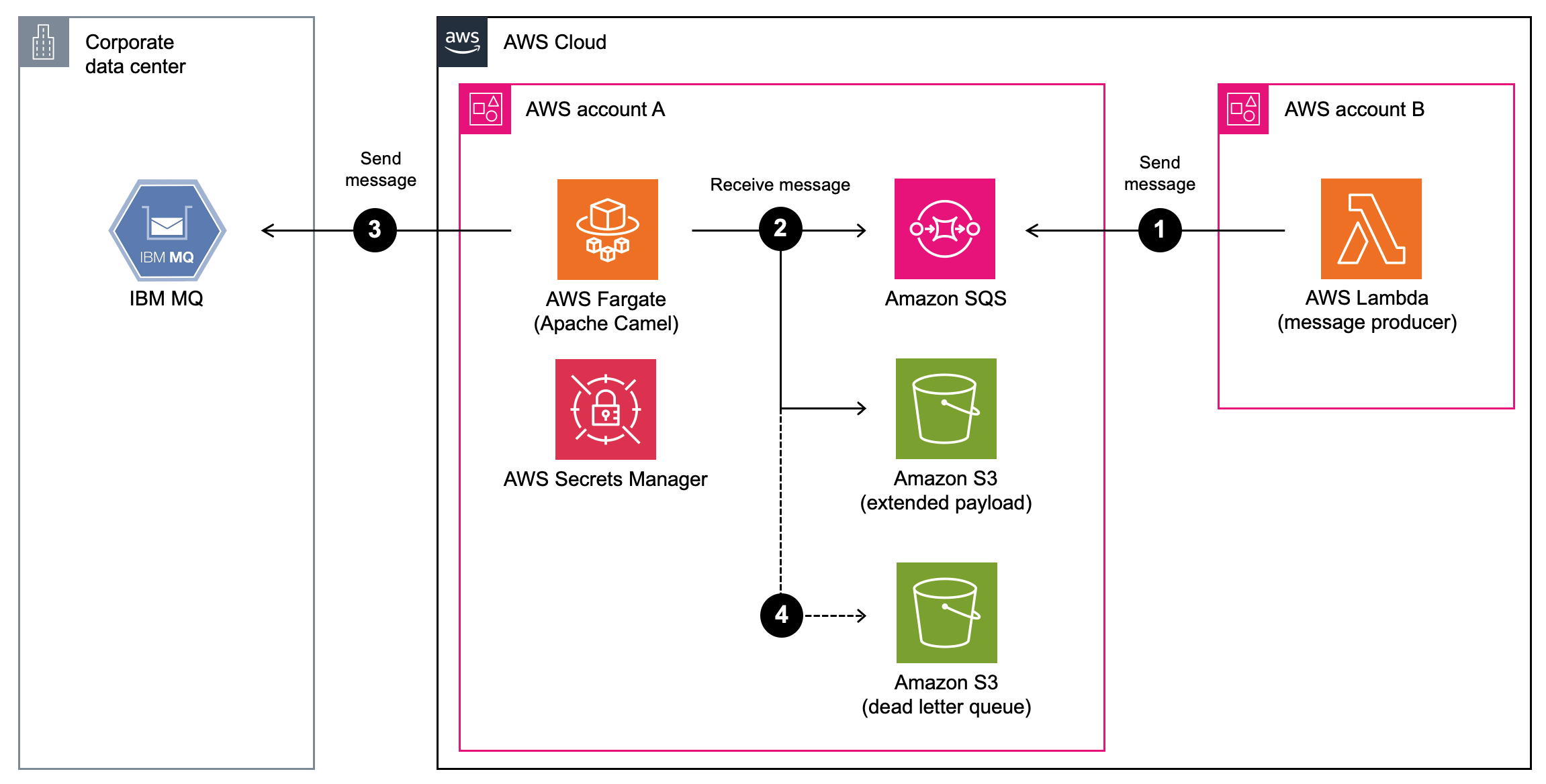
IBM MQ is a message-oriented middleware (MOM) product used by many enterprise organizations, including global banks, airlines, and healthcare and insurance companies.
Customers often ask us for guidance on how they can integrate their existing on-premises MOM systems with new applications running in the cloud. They’re looking for a cost-effective, scalable and low-effort solution that enables them to send and receive messages from their cloud applications to these messaging systems.
This allows your producer and consumer applications to integrate using fully managed AWS messaging services and Apache Camel. Learn how to deploy such a solution and how to test the running integration using SNS, SQS, and a demo IBM MQ cluster environment running on Amazon Elastic Container Service (ECS) with AWS Fargate.
The integration consists of an Apache Camel broker cluster that bi-directionally integrates an IBM MQ system and target systems, such as Amazon MQ running ActiveMQ, SNS topics, or SQS queues.
In the following example, AWS services, in this case AWS Lambda and SQS, receive messages published to IBM MQ via an SNS topic:
The cloud message consumers (Lambda and SQS) subscribe to the solution’s target SNS topic.
The Apache Camel broker connects to IBM MQ using secrets stored in AWS Secrets Manager and reads new messages from the queue using IBM MQ’s Java library. Only IBM MQ messages are supported as a source.
This demo uses IBM MQ’s mutual TLS authentication. To do this, you must generate X.509 certificates and store them in AWS Secrets Manager by running the following commands in the app folder:
Generate X.509 certificates:
./deploy.sh generate_secrets
Set up the secrets required for the Apache Camel broker (replace <integration-name> with, for example, dev):
Update the cdk.json file with the secrets ARN output from the previous commands:
IBM_MOCK_PUBLIC_CERT_ARN
IBM_MOCK_PRIVATE_CERT_ARN
IBM_MOCK_CLIENT_PUBLIC_CERT_ARN
IBMMQ_TRUSTSTORE_ARN
IBMMQ_TRUSTSTORE_PASSWORD_ARN
IBMMQ_KEYSTORE_ARN
IBMMQ_KEYSTORE_PASSWORD_ARN
If you are using your own IBM MQ system and already have X.509 certificates available, you can use the script to upload those certificates to AWS Secrets Manager after running the script.
Step 3: Configuring the broker
The solution deploys two brokers, one to read messages from the test IBM MQ system and one to send messages back. A separate Apache Camel cluster is used per integration to support better use of Auto Scaling functionality and to avoid issues across different integration operations (consuming and reading messages).
Update the cdk.json file with the following values:
accountId: AWS account ID to deploy the solution to.
region: name of the AWS Region to deploy the solution to.
defaultVPCId: specify a VPC ID for an existing VPC in the AWS account where the broker and mock are deployed.
allowedPrincipals: add your account ARN (e.g., arn:aws:iam::123456789012:root) to allow this AWS account to send messages to and receive messages from the broker. You can use this parameter to set up cross-account relationships for both SQS and SNS integrations and support multiple consumers and producers.
Step 4: Bootstrapping and deploying the solution
Make sure you have the correct AWS_PROFILE and AWS_REGION environment variables set for your development account.
Run yarn cdk bootstrap –-qualifier mq <aws://<account-id>/<region> to bootstrap CDK.
Run yarn install to install CDK dependencies.
Finally, execute yarn cdk deploy '*-dev' –-qualifier mq --require-approval never to deploy the solution to the dev environment.
In a command line terminal, make sure you have the correct AWS_PROFILE and AWS_REGION environment variables set for your development account.
In addition, set the following environment variables:
IBM_ENDPOINT: endpoint for IBM MQ. Example: network load balancer for IBM mock mqmoc-mqada-1234567890.elb.eu-west-1.amazonaws.com.
BASTION_ID: instance ID for the bastion host. You can retrieve this output from Step 4: Bootstrapping and deploying the solution listed after the mqBastionStack deployment.
Use the following command to set the environment variables:
Log in to the IBM web console via https://127.0.0.1:9443/admin using the default IBM user (admin) and the password stored in AWS Secrets Manager as mqAdapterIbmMockAdminPassword.
Sending data from IBM MQ and receiving it in SNS:
In the IBM MQ console, access the local queue manager QM1 and DEV.QUEUE.1.
Send a message with the content Hello AWS. This message will be processed by AWS Fargate and published to SNS.
Access the SQS console and choose the snsIntegrationStack-dev-2 prefix queue. This is an SQS queue subscribed to the SNS topic for testing.
Select Send and receive message.
Select Poll for messages to see the Hello AWS message previously sent to IBM MQ.
Sending data back from Amazon SQS to IBM MQ:
Access the SQS console and choose the queue with the prefix sqsPublishIntegrationStack-dev-3-dev.
Select Send and receive messages.
For Message Body, add Hello from AWS.
Choose Send message.
In the IBM MQ console, access the local queue manager QM1 and DEV.QUEUE.2 to find your message listed under this queue.
Step 6: Cleaning up
Run cdk destroy '*-dev' to destroy the resources deployed as part of this walkthrough.
Conclusion
In this blog, you learned how you can exchange messages between IBM MQ and your cloud applications using Amazon SQS and Amazon SNS.
If you’re interested in getting started with your own integration, follow the README file in the GitHub repository. If you’re migrating existing applications using industry-standard APIs and protocols such as JMS, NMS, or AMQP 1.0, consider integrating with Amazon MQ using the steps provided in the repository.
If you’re interested in running Apache Camel in Kubernetes, you can also adapt the architecture to use Apache Camel K instead.
For more serverless learning resources, visit Serverless Land.
The 2023 Maintainers Summit will be held on November 16 in Richmond, VA,
immediately after the Linux Plumbers
Conference.
As in previous years, the Maintainers Summit is invite-only, where
the primary focus will be process issues around Linux Kernel
Development. It will be limited to 30 invitees and a handful of
sponsored attendees.
The call for
topics has just gone out, with the first invitations to be sent within
a couple of weeks or so.
Security updates have been issued by Debian (samba), Red Hat (.NET 6.0, .NET 7.0, rh-dotnet60-dotnet, rust, rust-toolset-1.66-rust, and rust-toolset:rhel8), and SUSE (kernel and opensuse-welcome).
Dr Sue Sentance, Director of our Raspberry Pi Computing Education Research Centre at the University of Cambridge, shares what she learned on a recent visit in Malaysia to understand more about the approach taken to computing education in the state of Sarawak.
Dr Sue Sentance
Computing education is a challenge around the world, and it is fascinating to see how different countries and education systems approach it. I recently had the opportunity to attend an event organised by the government of Sarawak, Malaysia, to see first-hand what learners and teachers are achieving thanks to the state’s recent policies.
Raspberry Pis and training for Sarawak’s primary schools
In Sarawak, the largest state of Malaysia, the local Ministry of Education, Innovation and Talent Development is funding an ambitious project through which all of Sarawak’s primary schools are receiving sets of Raspberry Pis. Learners use these as desktop computers and to develop computer science skills and knowledge, including the skills to create digital making projects.
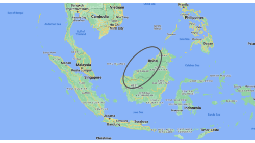
Sarawak is the largest state of Malaysia, situated on the island of Borneo
Crucially, the ministry is combining this hardware distribution initiative with a three-year programme of professional development for primary school teachers. They receive training known as the Raspberry Pi Training Programme, which starts with Scratch programming and incorporates elements of physical computing with the Raspberry Pis and sensors.
To date the project has provided 9436 kits (including Raspberry Pi computer, case, monitor, mouse, and keyboard) to schools, and training for over 1200 teachers.
The STEM Trailblazers event
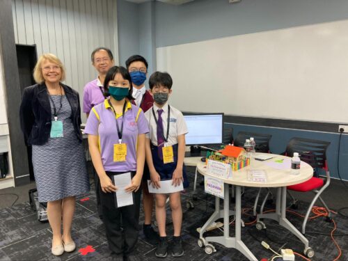
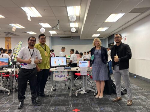
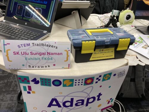
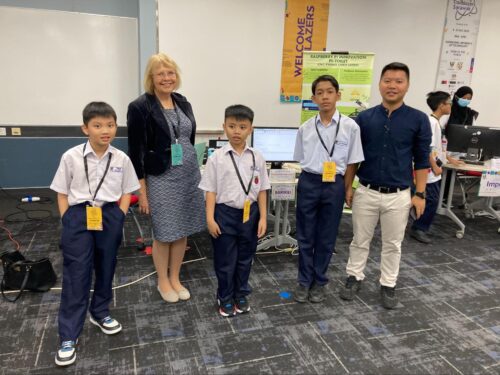
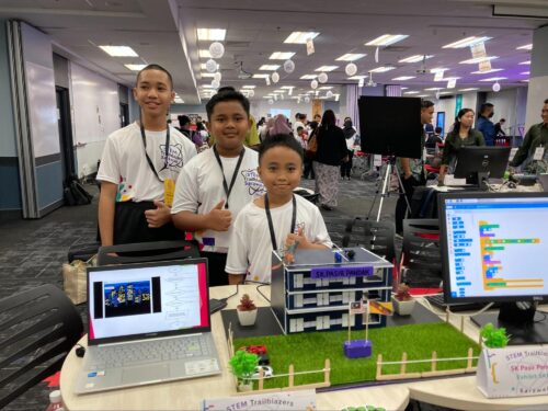
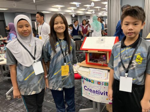
In order to showcase what has been achieved through the project so far, students and teachers were invited to use their schools’ Raspberry Pis to create projects to prototype solutions to real problems faced by their communities, and to showcase these projects at a special STEM Trailblazers event.
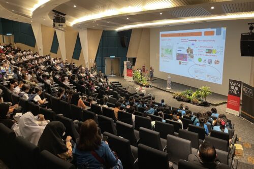
Geographically, Sarawak is Malaysia’s largest state, but it has a much smaller population than the west of the country. This means that towns and villages are very spread out and teachers and students had large distances to travel to attend the STEM Trailblazers event. To partially address this, the event was held in two locations simultaneously, Kuching and Miri, and talks were live-streamed between both venues.
STEM Trailblazers featured a host of talks from people involved in the initiative. I was very honoured to be invited as a guest speaker, representing both the University of Cambridge and the Raspberry Pi Foundation as the Director of the Raspberry Pi Computing Education Research Centre.
Solving real-world problems
The Raspberry Pi projects at STEM Trailblazers were entered into a competition, with prizes for students and teachers. Most projects had been created using Scratch to control the Raspberry Pi as well as a range of sensors.
The children and teachers who participated came from both rural and urban areas, and it was clear that the issues they had chosen to address were genuine problems in their communities.
Many of the projects I saw related to issues that schools faced around heat and hydration: a Smart Bottle project reminded children to drink regularly, a shade creator project created shade when the temperature got too high, a teachers’ project told students that they could no longer play outside when the temperature exceeded 35 degrees, and a water cooling system project set off sprinklers when the temperature rose. Other themes of the projects were keeping toilets clean, reminding children to eat healthily, and helping children to learn the alphabet. One project that especially intrigued me was an alert system for large and troublesome birds that were a problem for rural schools.
The creativity and quality of the projects on show was impressive given that all the students (and many of their teachers) had learned to program very recently, and also had to be quite innovative where they hadn’t been able to access all the hardware they needed to build their creations.
What we can learn from this initiative
Everyone involved in this project in Sarawak — including teachers, government representatives, university academics, and industry partners — is really committed to giving children the best opportunities to grow up with an understanding of digital technology. They know this is essential for their professional futures, and also fosters their creativity, independence, and problem-solving skills.
Over the last ten years, I’ve been fortunate enough to travel widely in my capacity as a computing education researcher, and I’ve seen first-hand a number of the approaches countries are taking to help their young people gain the skills and understanding of computing technologies that they need for their futures.
It’s good for us to look beyond our own context to understand how countries across the world are preparing their young people to engage with digital technology. No matter how many similarities there are between two places, we can all learn from each other’s initiatives and ideas. In 2021 the Brookings Institution published a global review of how countries are progressing with this endeavour. Organisations such as UNESCO and WEF regularly publish reports that emphasise the importance for countries to develop their citizens’ digital skills, and also advanced technological skills.
The Sarawak government’s initiative is grounded in the use of Raspberry Pis as desktop computers for schools, which run offline where schools have no access to the internet. That teachers are also trained to use the Raspberry Pis to support learners to develop hands-on digital making skills is a really important aspect of the project.
As for what the future holds for Sarawak’s computing education, at the opening ceremony of the STEM Trailblazers event, the Deputy Minister announced that the event will be an annual occasion. That means every year more students and teachers will be able to come together, share their learning, and get excited about using digital making to solve the problems that matter to them.
Zoom updated its Terms of Service in March, spelling out that the company reserves the right to train AI on user data with no mention of a way to opt out. On Monday, the company said in a blog post that there’s no need to worry about that. Zoom execs swear the company won’t actually train its AI on your video calls without permission, even though the Terms of Service still say it can.
Of course, these are Terms of Service. They can change at any time. Zoom can renege on its promise at any time. There are no rules, only the whims of the company as it tries to maximize its profits.
It’s a stupid way to run a technological revolution. We should not have to rely on the benevolence of for-profit corporations to protect our rights. It’s not their job, and it shouldn’t be.
Launched in 2019, Segmentation Platform has been Grab’s one-stop platform for user segmentation and audience creation across all business verticals. User segmentation is the process of dividing passengers, driver-partners, or merchant-partners (users) into sub-groups (segments) based on certain attributes. Segmentation Platform empowers Grab’s teams to create segments using attributes available within our data ecosystem and provides APIs for downstream teams to retrieve them.
Checking whether a user belongs to a segment (Membership Check) influences many critical flows on the Grab app:
When a passenger launches the Grab app, our in-house experimentation platform will tailor the app experience based on the segments the passenger belongs to.
When a driver-partner goes online on the Grab app, the Drivers service calls Segmentation Platform to ensure that the driver-partner is not blacklisted.
When launching marketing campaigns, Grab’s communications platform relies on Segmentation Platform to determine which passengers, driver-partners, or merchant-partners to send communication to.
This article peeks into the current design of Segmentation Platform and how the team optimised the way segments are stored to reduce read latency thus unlocking new segmentation use cases.
Architecture
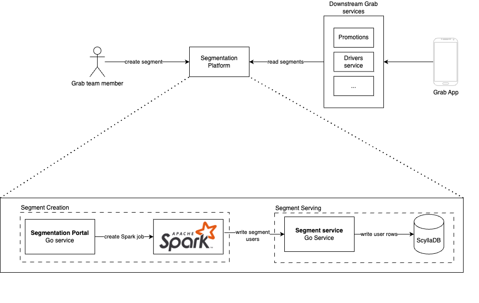
Segmentation Platform comprises two major subsystems:
Segment creation
Segment serving
Fig 1. Segmentation Platform architecture
Segment creation
Segment creation is powered by Spark jobs. When a Grab team creates a segment, a Spark job is started to retrieve data from our data lake. After the data is retrieved, cleaned, and validated, the Spark job calls the serving sub-system to populate the segment with users.
Segment serving
Segment serving is powered by a set of Go services. For persistence and serving, we use ScyllaDB as our primary storage layer. We chose to use ScyllaDB as our NoSQL store due to its ability to scale horizontally and meet our <80ms p99 SLA. Users in a segment are stored as rows indexed by the user ID. The table is partitioned by the user ID ensuring that segment data is evenly distributed across the ScyllaDB clusters.
User ID
Segment Name
Other metadata columns
1221
Segment_A
…
3421
Segment_A
…
5632
Segment_B
…
7889
Segment_B
…
With this design, Segmentation Platform handles up to 12K read and 36K write QPS, with a p99 latency of 40ms.
Problems
The existing system has supported Grab, empowering internal teams to create rich and personalised experiences. However, with the increased adoption and use, certain challenges began to emerge:
As more and larger segments are being created, the write QPS became a bottleneck leading to longer wait times for segment creation.
Grab services requested even lower latency for membership checks.
Long segment creation times
As more segments were created by different teams within Grab, the write QPS was no longer able to keep up with the teams’ demands. Teams would have to wait for hours for their segments to be created, reducing their operational velocity.
Read latency
Further, while the platform already offers sub-40ms p99 latency for reads, this was still too slow for certain services and their use cases. For example, Grab’s communications platform needed to check whether a user belongs to a set of segments before sending out communication and incurring increased latency for every communication request was not acceptable. Another use case was for Experimentation Platform, where checks must have low latency to not impact the user experience.
Thus, the team explored alternative ways of storing the segment data with the goals of:
Reducing segment creation time
Reducing segment read latency
Maintaining or reducing cost
Solution
Segments as bitmaps
One of the main engineering challenges was scaling the write throughput of the system to keep pace with the number of segments being created. As a segment is stored across multiple rows in ScyllaDB, creating a large segment incurs a huge number of writes to the database. What we needed was a better way to store a large set of user IDs. Since user IDs are represented as integers in our system, a natural solution to storing a set of integers was a bitmap.
For example, a segment containing the following user IDs: 1, 6, 25, 26, 89 could be represented with a bitmap as follows:
Fig 2. Bitmap representation of a segment
To perform a membership check, a bitwise operation can be used to check if the bit at the user ID’s index is 0 or 1. As a bitmap, the segment can also be stored as a single Blob in object storage instead of inside ScyllaDB.
However, as the number of user IDs in the system is large, a small and sparse segment would lead to prohibitively large bitmaps. For example, if a segment contains 2 user IDs 100 and 200,000,000, it will require a bitmap containing 200 million bits (25MB) where all but 2 of the bits are just 0. Thus, the team needed an encoding to handle sparse segments more efficiently.
Roaring Bitmaps
After some research, we landed on Roaring Bitmaps, which are compressed uint32 bitmaps. With roaring bitmaps, we are able to store a segment with 1 million members in a Blob smaller than 1 megabyte, compared to 4 megabytes required by a naive encoding.
Roaring Bitmaps achieve good compression ratios by splitting the set into fixed-size (216) integer chunks and using three different data structures (containers) based on the data distribution within the chunk. The most significant 16 bits of the integer are used as the index of the chunk, and the least significant 16 bits are stored in the containers.
Array containers
Array containers are used when data is sparse (<= 4096 values). An array container is a sorted array of 16-bit integers. It is memory-efficient for sparse data and provides logarithmic-time access.
Bitmap containers
Bitmap containers are used when data is dense. A bitmap container is a 216 bit container where each bit represents the presence or absence of a value. It is memory-efficient for dense data and provides constant-time access.
Run containers
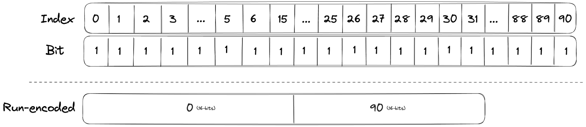
Finally, run containers are used when a chunk has long consecutive values. Run containers use run-length encoding (RLE) to reduce the storage required for dense bitmaps. Run containers store a pair of values representing the start and the length of the run. It provides good memory efficiency and fast lookups.
The diagram below shows how a dense bitmap container that would have required 91 bits can be compressed into a run container by storing only the start (0) and the length (90). It should be noted that run containers are used only if it reduces the number of bytes required compared to a bitmap.
Fig 3. A dense bitmap container compressed into a run container
By using different containers, Roaring Bitmaps are able to achieve good compression across various data distributions, while maintaining excellent lookup performance. Additionally, as segments are represented as Roaring Bitmaps, service teams are able to perform set operations (union, interaction, and difference, etc) on the segments on the fly, which previously required re-materialising the combined segment into the database.
Caching with an SDK
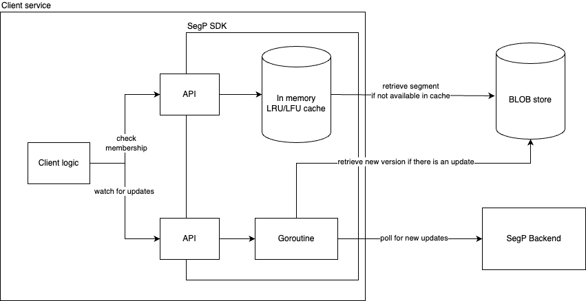
Even though the segments are now compressed, retrieving a segment from the Blob store for each membership check would incur an unacceptable latency penalty. To mitigate the overhead of retrieving a segment, we developed an SDK that handles the retrieval and caching of segments.
Fig 4. How the SDK caches segments
The SDK takes care of the retrieval, decoding, caching, and watching of segments. Users of the SDK are only required to specify the maximum size of the cache to prevent exhausting the service’s memory. The SDK provides a cache with a least-recently-used eviction policy to ensure that hot segments are kept in the cache. They are also able to watch for updates on a segment and the SDK will automatically refresh the cached segment when it is updated.
Hero teams
Communications Platform
Communications Platform has adopted the SDK to implement a new feature to control the communication frequency based on which segments a user belongs to. Using the SDK, the team is able to perform membership checks on multiple multi-million member segments, achieving peak QPS 15K/s with a p99 latency of <1ms. With the new feature, they have been able to increase communication engagement and reduce the communication unsubscribe rate.
Experimentation Platform
Experimentation Platform powers experimentation across all Grab services. Segments are used heavily in experiments to determine a user’s experience. Prior to using the SDK, Experimentation Platform limited the maximum size of the segments that could be used to prevent exhausting a service’s memory.
After migrating to the new SDK, they were able to lift this restriction due to the compression efficiency of Roaring Bitmaps. Users are now able to use any segments as part of their experiment without worrying that it would require too much memory.
Closing
This blog post discussed the challenges that Segmentation Platform faced when scaling and how the team explored alternative storage and encoding techniques to improve segment creation time, while also achieving low latency reads. The SDK allows our teams to easily make use of segments without having to handle the details of caching, eviction, and updating of segments.
Moving forward, there are still existing use cases that are not able to use the Roaring Bitmap segments and thus continue to rely on segments from ScyllaDB. Therefore, the team is also taking steps to optimise and improve the scalability of our service and database.
Special thanks to Axel, the wider Segmentation Platform team, and Data Technology team for reviewing the post.
Join us
Grab is the leading superapp platform in Southeast Asia, providing everyday services that matter to consumers. More than just a ride-hailing and food delivery app, Grab offers a wide range of on-demand services in the region, including mobility, food, package and grocery delivery services, mobile payments, and financial services across 428 cities in eight countries.
Powered by technology and driven by heart, our mission is to drive Southeast Asia forward by creating economic empowerment for everyone. If this mission speaks to you, join our team today!
The AWS Cloud Development Kit (AWS CDK) is a popular open source toolkit that allows developers to create their cloud infrastructure using high level programming languages. AWS CDK comes bundled with a construct called CDK Pipelines that makes it easy to set up continuous integration, delivery, and deployment with AWS CodePipeline. The CDK Pipelines construct does all the heavy lifting, such as setting up appropriate AWS IAM roles for deployment across regions and accounts, Amazon Simple Storage Service (Amazon S3) buckets to store build artifacts, and an AWS CodeBuild project to build, test, and deploy the app. The pipeline deploys a given CDK application as one or more AWS CloudFormation stacks.
With CloudFormation stacks, there is the possibility that someone can manually change the configuration of stack resources outside the purview of CloudFormation and the pipeline that deploys the stack. This causes the deployed resources to be inconsistent with the intent in the application, which is referred to as “drift”, a situation that can make the application’s behavior unpredictable. For example, when troubleshooting an application, if the application has drifted in production, it is difficult to reproduce the same behavior in a development environment. In other cases, it may introduce security vulnerabilities in the application. For example, an AWS EC2 SecurityGroup that was originally deployed to allow ingress traffic from a specific IP address might potentially be opened up to allow traffic from all IP addresses.
CloudFormation offers a drift detection feature for stacks and stack resources to detect configuration changes that are made outside of CloudFormation. The stack/resource is considered as drifted if its configuration does not match the expected configuration defined in the CloudFormation template and by extension the CDK code that synthesized it.
In this blog post you will see how CloudFormation drift detection can be integrated as a pre-deployment validation step in CDK Pipelines using an event driven approach.
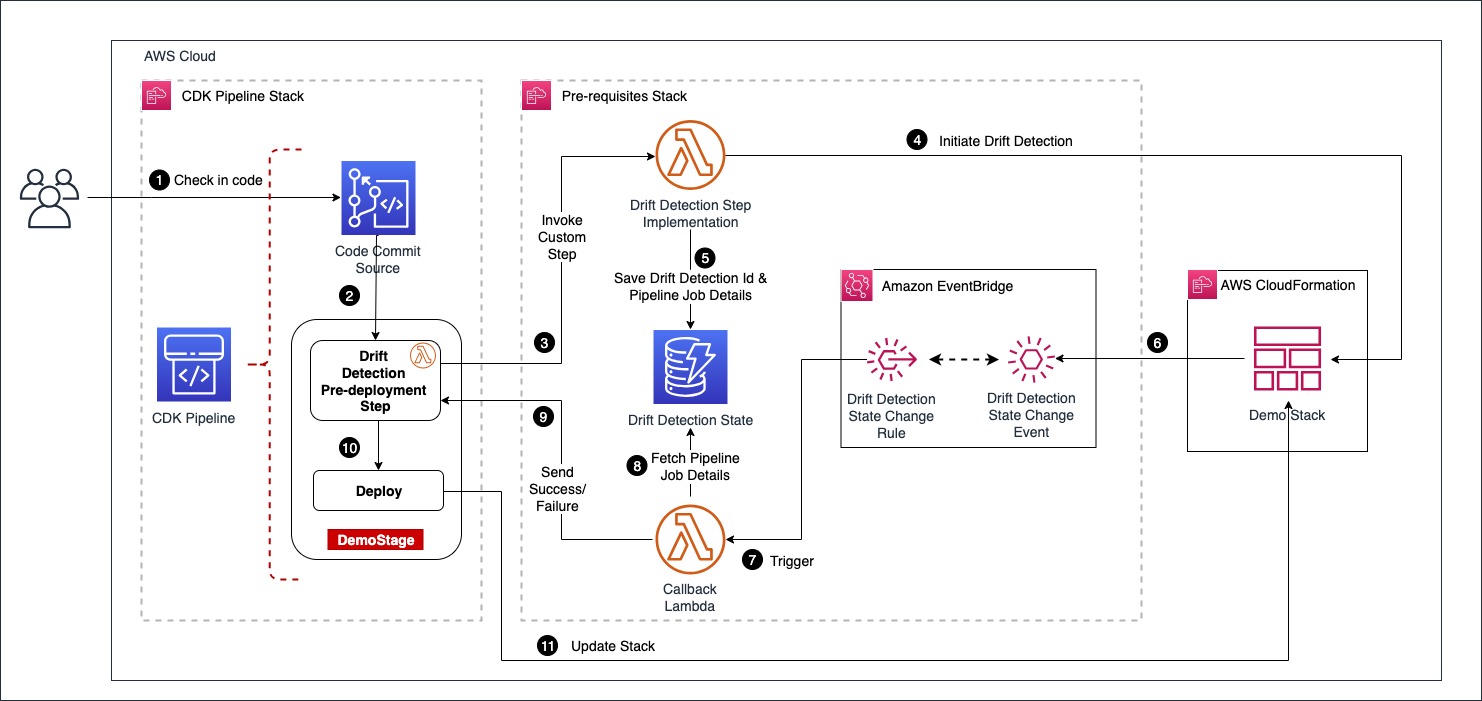
Amazon EventBridge is a serverless AWS service that offers an agile mechanism for the developers to spin up loosely coupled, event driven applications at scale. EventBridge supports routing of events between services via an event bus. EventBridge out of the box supports a default event bus for each account which receives events from AWS services. Last year, CloudFormation added a new feature that enables event notifications for changes made to CloudFormation-based stacks and resources. These notifications are accessible through Amazon EventBridge, allowing users to monitor and react to changes in their CloudFormation infrastructure using event-driven workflows. Our solution leverages the drift detection events that are now supported by EventBridge. The following architecture diagram depicts the flow of events involved in successfully performing drift detection in CDK Pipelines.
Architecture diagram
The user starts the pipeline by checking code into an AWS CodeCommit repo, which acts as the pipeline source. We have configured drift detection in the pipeline as a custom step backed by a lambda function. When the drift detection step invokes the provider lambda function, it first starts the drift detection on the CloudFormation stack Demo Stack and then saves the drift_detection_id along with pipeline_job_id in a DynamoDB table. In the meantime, the pipeline waits for a response on the status of drift detection.
The EventBridge rules are set up to capture the drift detection state change events for Demo Stack that are received by the default event bus. The callback lambda is registered as the intended target for the rules. When drift detection completes, it triggers the EventBridge rule which in turn invokes the callback lambda function with stack status as either DRIFTED or IN SYNC. The callback lambda function pulls the pipeline_job_id from DynamoDB and sends the appropriate status back to the pipeline, thus propelling the pipeline out of the wait state. If the stack is in the IN SYNC status, the callback lambda sends a success status and the pipeline continues with the deployment. If the stack is in the DRIFTED status, callback lambda sends failure status back to the pipeline and the pipeline run ends up in failure.
Solution Deep Dive
The solution deploys two stacks as shown in the above architecture diagram
CDK Pipelines stack
Pre-requisite stack
The CDK Pipelines stack defines a pipeline with a CodeCommit source and drift detection step integrated into it. The pre-requisite stack deploys following resources that are required by the CDK Pipelines stack.
A Lambda function that implements drift detection step
A DynamoDB table that holds drift_detection_id and pipeline_job_id
An Event bridge rule to capture “CloudFormation Drift Detection Status Change” event
A callback lambda function that evaluates status of drift detection and sends status back to the pipeline by looking up the data captured in DynamoDB.
The pre-requisites stack is deployed first, followed by the CDK Pipelines stack.
Defining drift detection step
CDK Pipelines offers a mechanism to define your own step that requires custom implementation. A step corresponds to a custom action in CodePipeline such as invoke lambda function. It can exist as a pre or post deployment action in a given stage of the pipeline. For example, your organization’s policies may require its CI/CD pipelines to run a security vulnerability scan as a prerequisite before deployment. You can build this as a custom step in your CDK Pipelines. In this post, you will use the same mechanism for adding the drift detection step in the pipeline.
You start by defining a class called DriftDetectionStep that extends Step and implements ICodePipelineActionFactory as shown in the following code snippet. The constructor accepts 3 parameters stackName, account, region as inputs. When the pipeline runs the step, it invokes the drift detection lambda function with these parameters wrapped inside userParameters variable. The function produceAction() adds the action to invoke drift detection lambda function to the pipeline stage.
Please note that the solution uses an SSM parameter to inject the lambda function ARN into the pipeline stack. So, we deploy the provider lambda function as part of pre-requisites stack before the pipeline stack and publish its ARN to the SSM parameter. The CDK code to deploy pre-requisites stack can be found here.
export class DriftDetectionStep
    extends Step
    implements pipelines.ICodePipelineActionFactory
{
    constructor(
        private readonly stackName: string,
        private readonly account: string,
        private readonly region: string
    ) {
        super(`DriftDetectionStep-${stackName}`);
    }

    public produceAction(
        stage: codepipeline.IStage,
        options: ProduceActionOptions
    ): CodePipelineActionFactoryResult {
        // Define the configuraton for the action that is added to the pipeline.
        stage.addAction(
            new cpactions.LambdaInvokeAction({
                actionName: options.actionName,
                runOrder: options.runOrder,
                lambda: lambda.Function.fromFunctionArn(
                    options.scope,
                    `InitiateDriftDetectLambda-${this.stackName}`,
                    ssm.StringParameter.valueForStringParameter(
                        options.scope,
                        SSM_PARAM_DRIFT_DETECT_LAMBDA_ARN
                    )
                ),
                // These are the parameters passed to the drift detection step implementaton provider lambda
                userParameters: {
                    stackName: this.stackName,
                    account: this.account,
                    region: this.region,
                },
            })
        );
        return {
            runOrdersConsumed: 1,
        };
    }
}
Configuring drift detection step in CDK Pipelines
Here you will see how to integrate the previously defined drift detection step into CDK Pipelines. The pipeline has a stage called DemoStage as shown in the following code snippet. During the construction of DemoStage, we declare drift detection as the pre-deployment step. This makes sure that the pipeline always does the drift detection check prior to deployment.
Please note that for every stack defined in the stage; we add a dedicated step to perform drift detection by instantiating the class DriftDetectionStep detailed in the prior section. Thus, this solution scales with the number of stacks defined per stage.
Here you will go through the deployment steps for the solution and see drift detection in action.
Deploy the pre-requisites stack
Clone the repo from the GitHub location here. Navigate to the cloned folder and run script script-deploy.sh You can find detailed instructions in README.md
Deploy the CDK Pipelines stack
Clone the repo from the GitHub location here. Navigate to the cloned folder and run script script-deploy.sh. This deploys a pipeline with an empty CodeCommit repo as the source. The pipeline run ends up in failure, as shown below, because of the empty CodeCommit repo.
Next, check in the code from the cloned repo into the CodeCommit source repo. You can find detailed instructions on that in README.md This triggers the pipeline and pipeline finishes successfully, as shown below.
The pipeline deploys two stacks DemoStackA and DemoStackB. Each of these stacks creates an S3 bucket.
Demonstrate drift detection
Locate the S3 bucket created by DemoStackA under resources, navigate to the S3 bucket and modify the tag aws-cdk:auto-delete-objects from true to false as shown below
Now, go to the pipeline and trigger a new execution by clicking on Release Change
The pipeline run will now end in failure at the pre-deployment drift detection step.
Cleanup
Please follow the steps below to clean up all the stacks.
Navigate to S3 console and empty the buckets created by stacks DemoStackA and DemoStackB.
Navigate to the CloudFormation console and delete stacks DemoStackA and DemoStackB, since deleting CDK Pipelines stack does not delete the application stacks that the pipeline deploys.
Delete the CDK Pipelines stack cdk-drift-detect-demo-pipeline
Delete the pre-requisites stack cdk-drift-detect-demo-drift-detection-prereq
Conclusion
In this post, I showed how to add a custom implementation step in CDK Pipelines. I also used that mechanism to integrate a drift detection check as a pre-deployment step. This allows us to validate the integrity of a CloudFormation Stack before its deployment. Since the validation is integrated into the pipeline, it is easier to manage the solution in one place as part of the overarching pipeline. Give the solution a try, and then see if you can incorporate it into your organization’s delivery pipelines.
About the author:
Damodar Shenvi Wagle is a Senior Cloud Application Architect at AWS Professional Services. His areas of expertise include architecting serverless solutions, CI/CD, and automation.
Load testing is a foundational pillar of building resilient applications. Today, load testing practices across many organizations are often based on desktop tools, where someone must manually run the performance tests and validate the results before a software release can be promoted to production. This leads to increased time to market for new features and products. Load testing applications in automated CI/CD pipelines provides the following benefits:
Early and automated feedback on performance thresholds based on clearly defined benchmarks.
Consistent and reliable load testing process for every feature release.
Reduced overall time to market due to eliminated manual load testing effort.
Improved overall resiliency of the production environment.
The ability to rapidly identify and document bottlenecks and scaling limits of the production environment.
The AWS Cloud Development Kit (AWS CDK) is an open-source software development framework to define cloud infrastructure in code and provision it through AWS CloudFormation. AWS CDK Pipelines is a construct library module for continuous delivery of AWS CDK applications, powered by AWS CodePipeline. AWS CDK Pipelines can automatically build, test, and deploy the new version of your CDK app whenever the new source code is checked in.
Distributed Load Testing is an AWS Solution that automates software applications testing at scale to help you identify potential performance issues before their release. It creates and simulates thousands of users generating transactional records at a constant pace without the need to provision servers or instances.
Prerequisites
To deploy and test this solution, you will need:
AWS Command Line Interface (AWS CLI): This tutorial assumes that you have configured the AWS CLI on your workstation. Alternatively, you can use also use AWS CloudShell.
AWS CDK V2: This tutorial assumes that you have installed AWS CDK V2 on your workstation or in the CloudShell environment.
Solution Overview
In this solution, we create a CI/CD pipeline using AWS CDK Pipelines and use it to deploy a sample RESTful CDK application in two environments; development and production. We load test the application using AWS Distributed Load Testing Solution in the development environment. Based on the load test result, we either fail the pipeline or proceed to production deployment. You may consider running the load test in a dedicated testing environment that mimics the production environment.
For demonstration purposes, we use the following metrics to validate the load test results.
Average Response Time – the average response time, in seconds, for all the requests generated by the test. In this blog post we define the threshold for average response time to 1 second.
Error Count – the total number of errors. In this blog post, we define the threshold for for total number of errors to 1.
For your application, you may consider using additional metrics from the Distributed Load Testing solution documentation to validate your load test.
The AWS Lambda (Lambda) function in the architecture contains a 500 millisecond sleep statement to add latency to the API response.
Typescript code for starting the load test and validating the test results. This code is executed in the ‘Load Test’ step of the ‘Development Deployment’ stage. It starts a load test against the sample restful application endpoint and waits for the test to finish. For demonstration purposes, the load test is started with the following parameters:
Concurrency: 1
Task Count: 1
Ramp up time: 0 secs
Hold for: 30 sec
End point to test: endpoint for the sample RESTful application.
For the purposes of this blog, we deploy the CI/CD pipeline, the RESTful application and the AWS Distributed Load Testing solution into the same AWS account. In your environment, you may consider deploying these stacks into separate AWS accounts based on your security and governance requirements.
To deploy the solution components
Follow the instructions in the the AWS Distributed Load Testing solution Automated Deployment guide to deploy the solution. Note down the value of the CloudFormation output parameter ‘DLTApiEndpoint’. We will need this in the next steps. Proceed to the next step once you are able to login to the User Interface of the solution.
Deploy the CloudFormation stack for the CI/CD pipeline. This step will also commit the AWS CDK code for the sample RESTful application stack and start the application deployment.
cd pipeline && cdk bootstrap && cdk deploy --require-approval never
Follow the below steps to view the load test results:
Open the AWS CodePipeline console.
Click on the pipeline named “blog-pipeline”.
Observe that one of the stages (named ‘LoadTest’) in the CI/CD pipeline (that was provisioned by the CloudFormation stack in the previous step) executes a load test against the application Development environment.
Click on the details of the ‘LoadTest’ step to view the test results. Notice that the load test succeeded.
Change the response time threshold
In this step, we will modify the response time threshold from 1 second to 200 milliseconds in order to introduce a load test failure. Remember from the steps earlier that the Lambda function code has a 500 millisecond sleep statement to add latency to the API response time.
From the AWS Console and then go to CodeCommit. The source for the pipeline is a CodeCommit repository named “blog-repo”.
Click on the “blog-repo” repository, and then browse to the “pipeline” folder. Click on file ‘loadTestEnvVariables.json’ and then ‘Edit’.
Set the response time threshold to 200 milliseconds by changing attribute ‘AVG_RT_THRESHOLD’ value to ‘.2’. Click on the commit button. This will start will start the CI/CD pipeline.
Go to CodePipeline from the AWS console and click on the ‘blog-pipeline’.
Observe the ‘LoadTest’ step in ‘Development-Deploy’ stage will fail in about five minutes, and the pipeline will not proceed to the ‘Production-Deploy’ stage.
Click on the details of the ‘LoadTest’ step to view the test results. Notice that the load test failed.
Log into the Distributed Load Testing Service console. You will see two tests named ‘sampleScenario’. Click on each of them to see the test result details.
Cleanup
Delete the CloudFormation stack that deployed the sample application.
From the AWS Console, go to CloudFormation and delete the stacks ‘Production-Deploy-Application’ and ‘Development-Deploy-Application’.
Delete the CI/CD pipeline.
cd pipeline && cdk destroy
Delete the Distributed Load Testing Service CloudFormation stack.
From CloudFormation console, delete the stack for Distributed Load Testing service that you created earlier.
Conclusion
In the post above, we demonstrated how to automatically load test your applications in a CI/CD pipeline using AWS CDK Pipelines and AWS Distributed Load Testing solution. We defined the performance bench marks for our application as configuration. We then used these benchmarks to automatically validate the application performance prior to production deployment. Based on the load test results, we either proceeded to production deployment or failed the pipeline.
About the Authors
The collective thoughts of the interwebz
Manage Consent
To provide the best experiences, we use technologies like cookies to store and/or access device information. Consenting to these technologies will allow us to process data such as browsing behavior or unique IDs on this site. Not consenting or withdrawing consent, may adversely affect certain features and functions.
Functional
Always active
The technical storage or access is strictly necessary for the legitimate purpose of enabling the use of a specific service explicitly requested by the subscriber or user, or for the sole purpose of carrying out the transmission of a communication over an electronic communications network.
Preferences
The technical storage or access is necessary for the legitimate purpose of storing preferences that are not requested by the subscriber or user.
Statistics
The technical storage or access that is used exclusively for statistical purposes.The technical storage or access that is used exclusively for anonymous statistical purposes. Without a subpoena, voluntary compliance on the part of your Internet Service Provider, or additional records from a third party, information stored or retrieved for this purpose alone cannot usually be used to identify you.
Marketing
The technical storage or access is required to create user profiles to send advertising, or to track the user on a website or across several websites for similar marketing purposes.


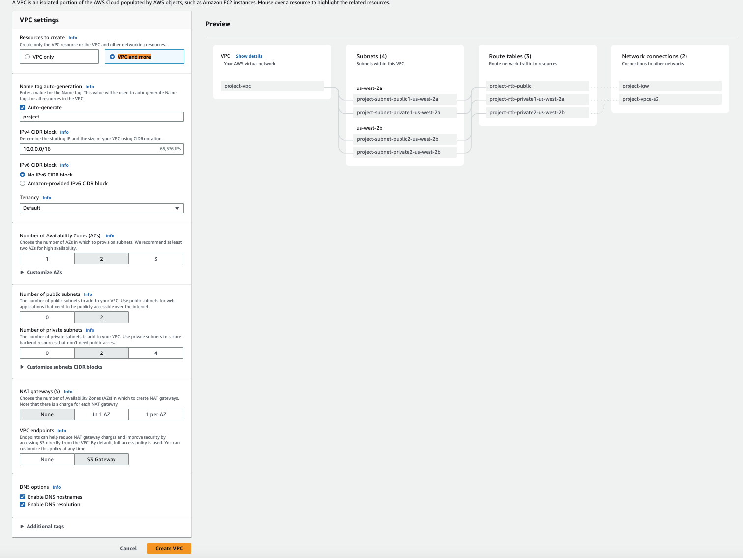
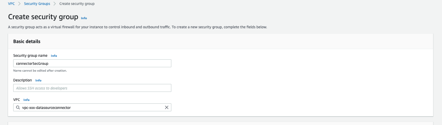
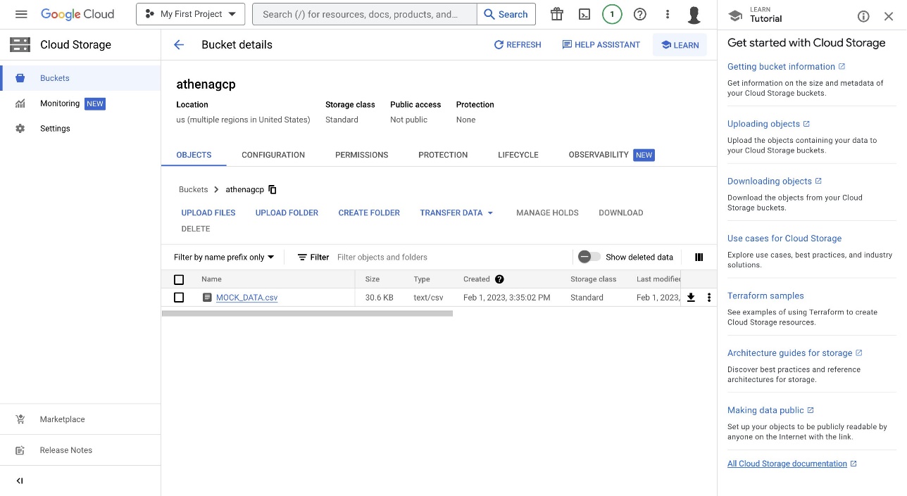
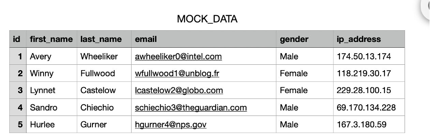
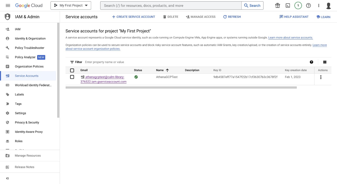
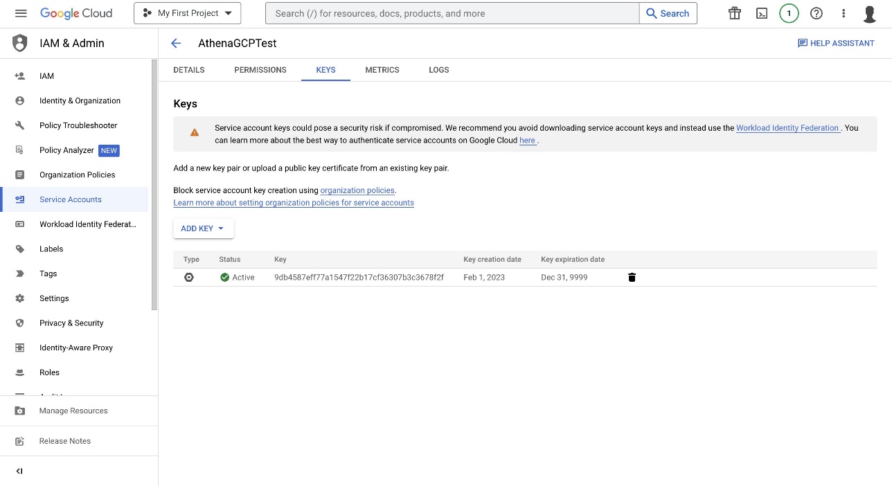
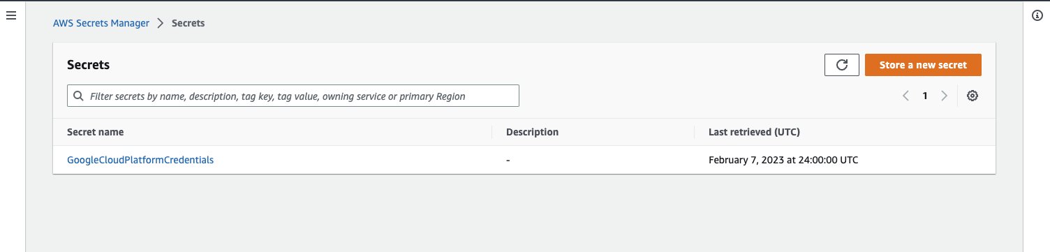
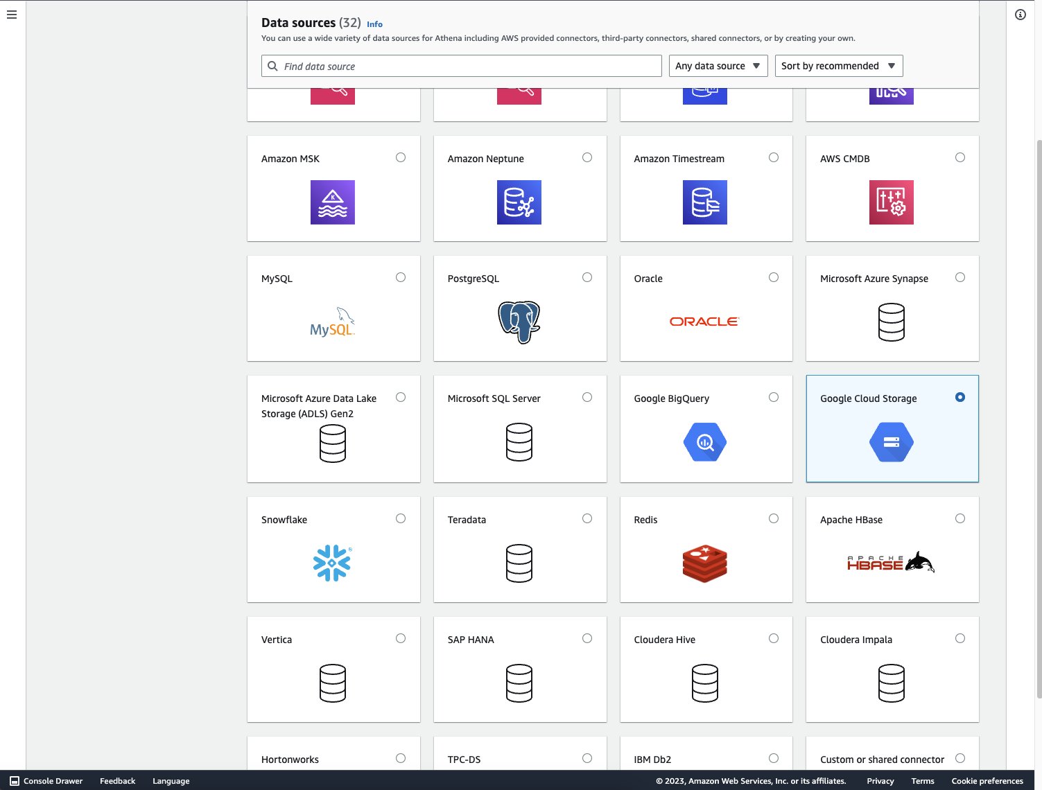
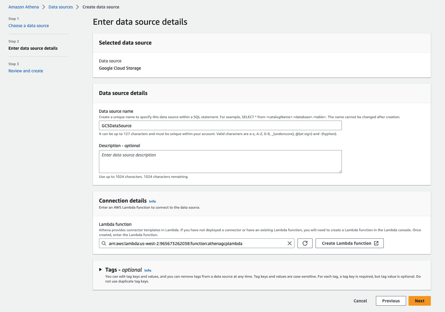
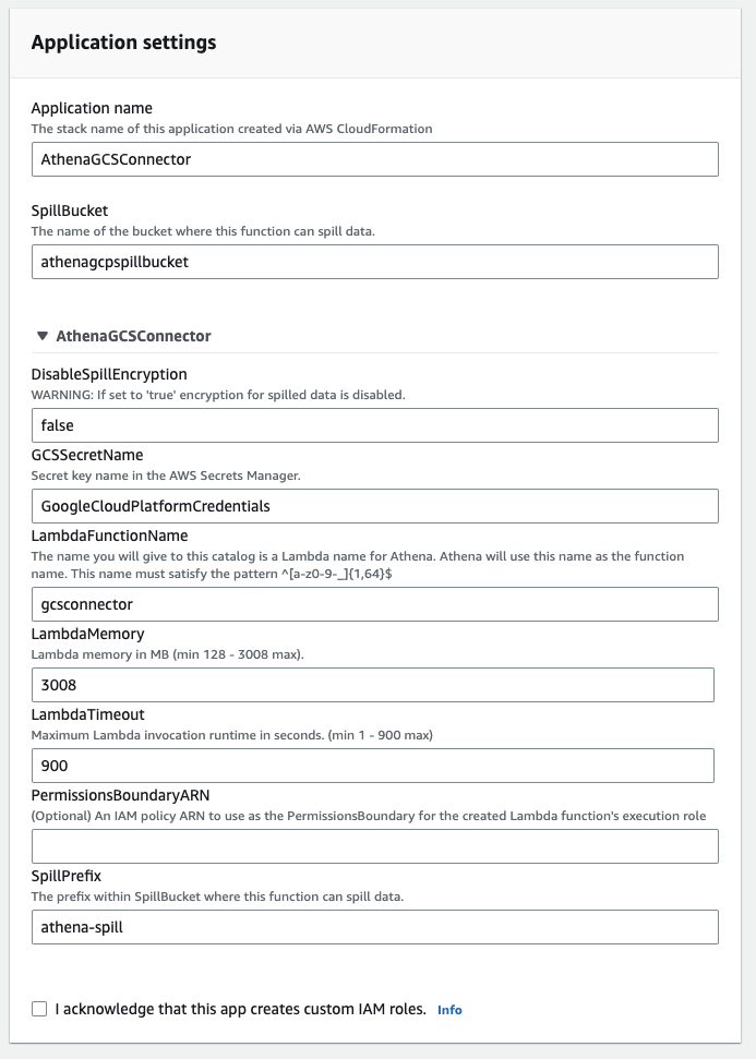
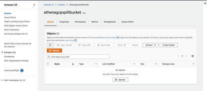
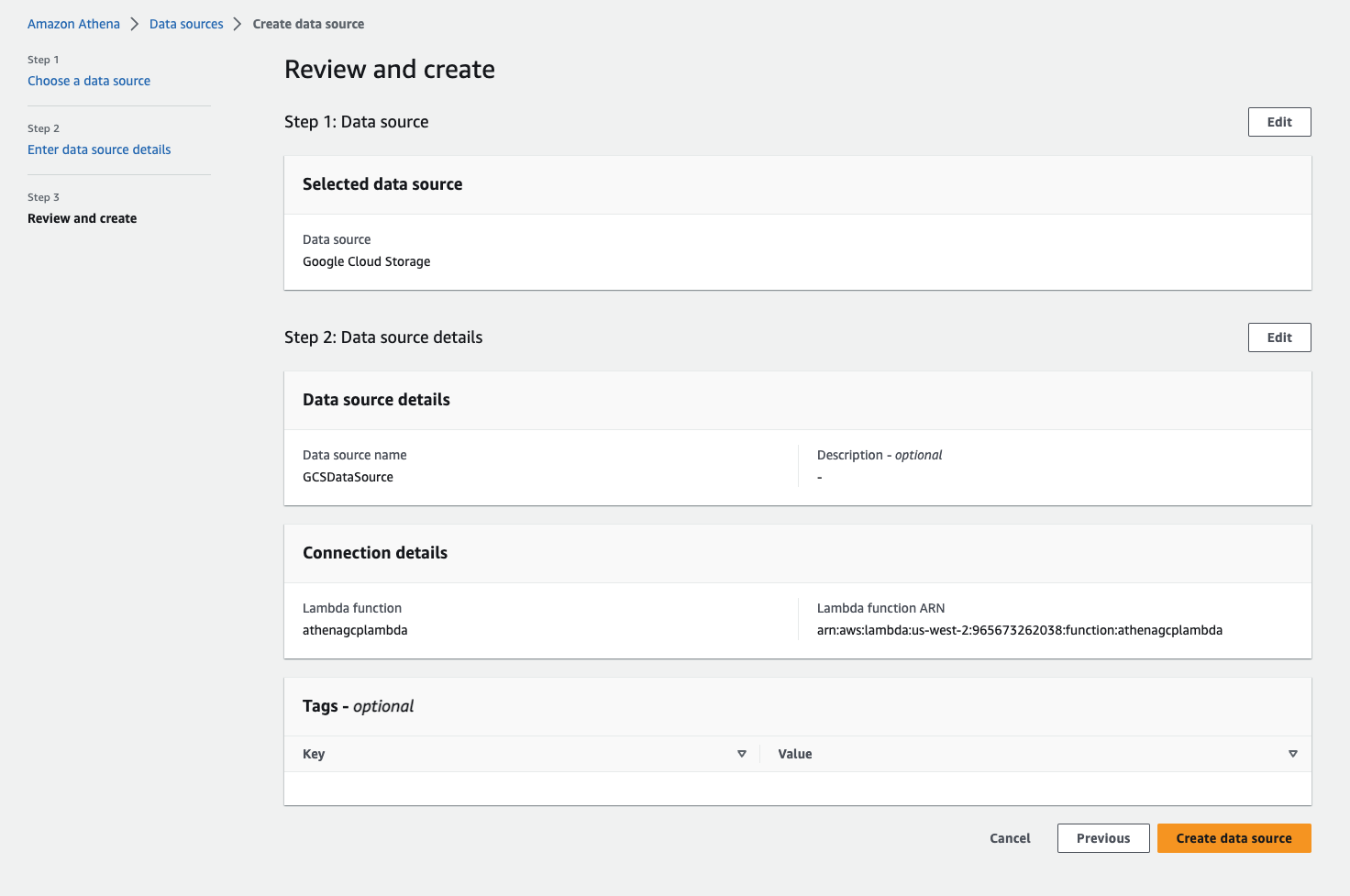
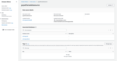

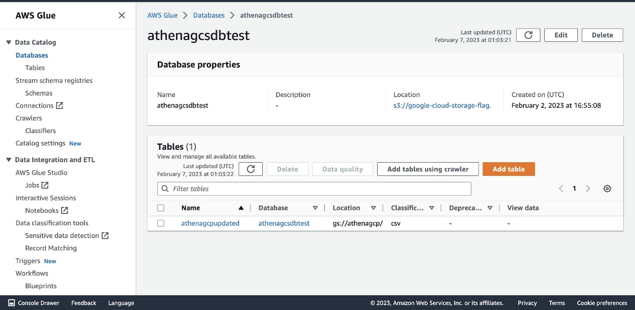
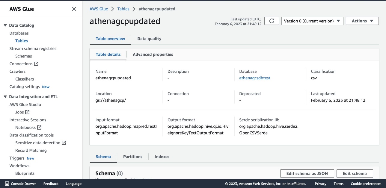
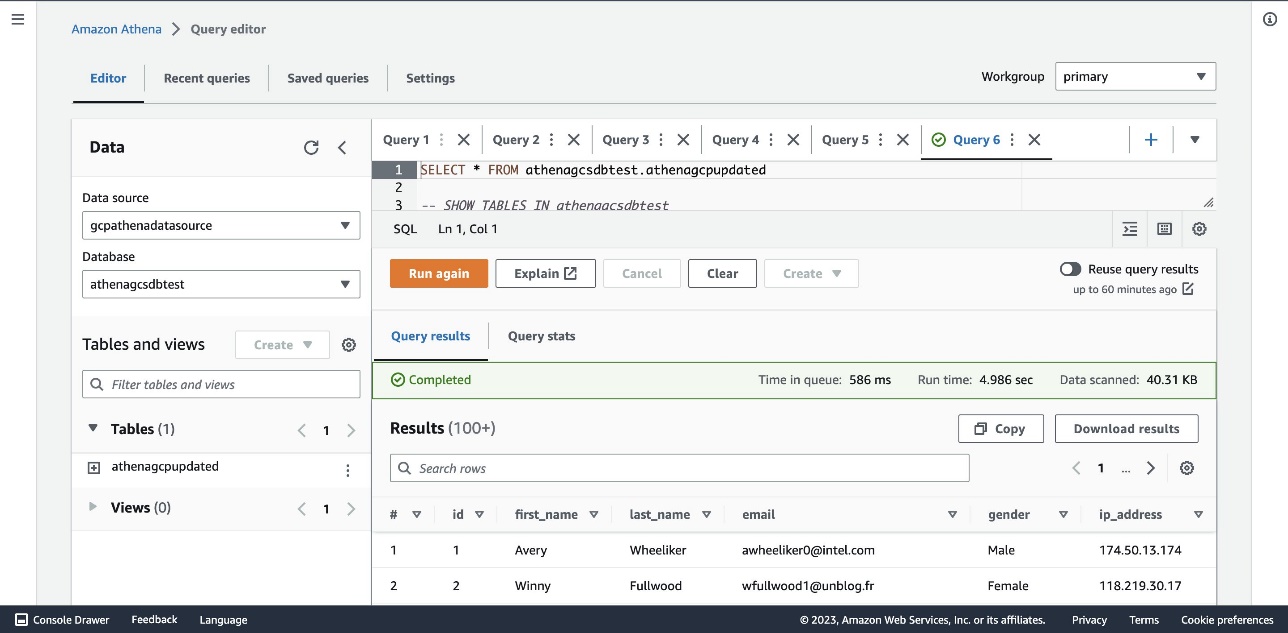
 Jonathan Wong is a Solutions Architect at AWS assisting with initiatives within Strategic Accounts. He is passionate about solving customer challenges and has been exploring emerging technologies to accelerate innovation.