In today’s fast-paced digital world, organizations are facing challenges for modernizing their applications. A common problem is the smooth shift from synchronous to asynchronous communication without substantial client or frontend alterations. When modernizing applications, it is often necessary to move from a synchronous communication model to an asynchronous one. However, this transition can be complex, especially when the client or frontend communicates synchronously. Adapting the current code for asynchronous communication demands significant time and resources.
AWS AppSync Events helps address this challenge by enabling you to build event-driven APIs that can bridge between synchronous and asynchronous communication models. With AppSync Events, you can modernize your backend architecture to leverage asynchronous patterns while maintaining compatibility with existing synchronous clients.
Overview
The solution comprises an API that converts client synchronous requests to asynchronous backend requests using AppSync Events.
For demonstrating the integration between the API and the backend, I’m simulating the backend processing using an asynchronous AWS Step Functions workflow. This workflow receives a Name and Surname event, waits 10 seconds, and posts a full-name event to the AppSync Event channel. To receive event notifications, the API subscribes to the AppSync channel. At the same time, the backend handles events asynchronously.
Figure 1: Representation of an API integrating a synchronous frontend with an asynchronous backend using AWS AppSync Events.
Lambda function starts the execution of the asynchronous workflow.
After starting the workflow execution, Lambda connects to AppSync and creates a channel to receive asynchronous notifications (channels are ephemeral and unlimited. Here it creates one channel per request using the workflow execution ID).
The workflow executes asynchronously, calling other workflows.
Upon completion of the main workflow, it sends a POST request to the AppSync events API with the processing result. The POST is made to the channel that was created by the Lambda function using the workflow execution ID.
AppSync receives the POST request and sends a notification to the subscriber, which in this case is the Lambda function. The entire process must be finished within the Lambda functions’s timeout limit you defined.
Lambda sends the response to the API Gateway, which has been waiting for the synchronous response.
To better understand the Event API WebSocket Protocol used in this solution, refer to this AppSync documentation.
With the full code, including API Gateway and Step Functions, on GitHub, this post only covers the core components: the AppSync Events API and the Lambda function.
Walkthrough
The following steps walk you through this solution.
Creating an AppSync event API with API Key Authorization
The infrastructure as code (IaC) has been created using Terraform. However, as of writing this post, there weren’t Terraform AppSync Event API resource available. Therefore, the AppSync Event API resources were made with AWS CloudFormation, which is imported and implemented by Terraform.
In the resource AWS:AppSync:Api, define the API name and Auth method:
Resources:
  #Creating the AppSync Events API
  EventAPI:
    Type: AWS::AppSync::Api
    Properties:
      Name: SyncAsyncAPI
      EventConfig:
        AuthProviders:
          - AuthType: API_KEY
        ConnectionAuthModes:
          - AuthType: API_KEY
        DefaultPublishAuthModes:
          - AuthType: API_KEY
        DefaultSubscribeAuthModes:
          - AuthType: API_KEY
#Creating the Events API Namespace
  DefaultNamespace:
    Type: AWS::AppSync::ChannelNamespace
    Properties:
      Name: AsyncEvents
      ApiId: !GetAtt EventAPI.ApiId

  #Creating the Events API APIKey
  EventAPIKey:
    Type: AWS::AppSync::ApiKey
    Properties:
      ApiId: !GetAtt EventAPI.ApiId
      Expires: 1748950672
      Description: 'API Key for Event API'

  #Creating the SecretsManager to store the APIKey
  SecretsManagerAPIKey:
    Type: AWS::SecretsManager::Secret
    Properties:
      Name: 'AppSyncEventAPIKEY'
      SecretString: !GetAtt EventAPIKey.ApiKey
To have the Host DNS, Realtime Endpoint, and Secret Manager created referenced by the Terraform template, output them:
Outputs:
  ApiARN:
    Description: 'The ARN ID'
    Value: !GetAtt EventAPI.ApiArn

  AppSyncHost:
    Description: 'The API Endpoint'
    Value: !GetAtt EventAPI.Dns.Http

  AppSyncRealTimeEndpoint:
    Description: 'The Real-time Endpoint'
    Value: !GetAtt EventAPI.Dns.Realtime

  SecretsManagerARN:
    Description: 'The ARN of the Secrets Manager entry'
    Value: !Ref SecretsManagerAPIKey
The key information needed from the AppSync Event API is:
Host DNS: This DNS is used to send events to the API Channel through HTTP Post requests.
Realtime endpoint: This endpoint is a WebSocket endpoint where the Lambda function connects to receive the events posted in the AppSync Channel.
API Key: This key is used not only in the Post HTTP requests, but also to connect and subscribe to the AppSync channel.
Lambda Sync/Async API
In this solution, the Lambda function runs two tasks:
Start an asynchronous workflow
Subscribe to an event channel through WebSocket
To handle the WebSocket connection, use the websocket-client lib, which is a powerful Python lib developed for working with WebSockets.
Request isolation is maintained by using the same UUID for workflow name and AppSync channel name.
Once the WebSocket connection is established, a first message with the type CONNECTION_INIT_TYPE must be sent.
To subscribe to the channel by which our function is notified when the Step Functions workflow finishes, send a second message with the type SUBSCRIBE_TYPE, an ID, the channel name and authorization.
For more information about types of message, read this AppSync documentation.
After receiving the message confirming the subscription, wait for messages with the type data. Whenever a message with this type arrives, execute the logic to identify if the workflow was successfully executed, and then close the connection.
def on_message(self, ws: websocket.WebSocketApp, message: str) -> None:
        """Handle incoming WebSocket messages."""
        logger.info("Message received: %s", message)
        try:
            message_dict = json.loads(message)
            required_keys = ["id", "type", "event"]

            if all(key in message_dict for key in required_keys):
                event_json = json.loads(message_dict["event"])

                if (message_dict["id"] == self.execution_name and
                    message_dict["type"] == "data"):

                    self.final_name = event_json["nome_completo"]
                    logger.info("Message received: %s", self.final_name)
                    logger.info("Successfully received return message")
                    logger.info("Ending processing")

                    self.message_queue = {
                        "status": SUCCESS_STATUS,
                        "executionID": message_dict["id"]
                    }
                    ws.close()
        except json.JSONDecodeError as e:
            logger.error("Failed to parse message: %s", str(e))
        except Exception as e:
            logger.error("Error processing message: %s", str(e))
Conclusion
In this post, you learned how to use event-driven architectures and the capabilities of AWS AppSync Events to integrate synchronous and asynchronous communication patterns in your applications. This allows you to modernize your systems without the need for extensive modifications to your existing frontend codebase. Explore the demonstrations and documentation provided in the GitHub repository to gain a deeper understanding of how AppSync Events can be applied to your specific use cases.
To learn more about serverless architectures and asynchronous invocation patterns, see Serverless Land.
In this post, you will learn how Amazon Web Services (AWS) customer, Maya, the Philippines’ leading fintech company and digital bank, built an API management platform to address the growing complexities of managing multiple APIs hosted on Amazon API Gateway. API Gateway is a fully managed service that you can use to create RESTful and WebSocket APIs.
At Maya, different teams build APIs to expose their services to merchants. As the number of applications grew, the overhead of managing APIs increased. An API platform is a set of tools to simplify and standardize across API management concerns such as security, governance, automated deployments, observability, and integrations with multiple AWS accounts. This frees up application teams to focus on features while offloading management concerns to the API platform.
Initial state
Prior to implementing the API platform, Maya used a decentralized API management approach, which created significant challenges. Individual teams operated independent API gateways, resulting in fragmented infrastructure, leading to several issues:
Lack of standardization: Implementing consistent API standards across the organization proved difficult. Each team maintained its own configurations and practices, leading to inconsistencies in security and documentation.
Security posture maintenance: While Maya maintained a strong security posture, doing so across the numerous independent gateways was unsustainable. The overhead of applying consistent security policies and updates across all gateways was becoming increasingly burdensome.
Inconsistent operational visibility: Observability wasn’t inherently limited, rather inconsistently applied. Having multiple, different gateways makes it challenging to enforce a unified observability strategy and correlate data across the entire API ecosystem.
Solution overview
To address these challenges, Maya implemented an API platform, code-named Unified API Gateway. This centralized API management helps enforce consistent standards and improve overall security and observability. The following image illustrates the architecture of the Unified API Gateway and how it integrates with backend services managed and owned by different teams across different AWS accounts.
API Platform Architecture
Maya chose to host all APIs in a central API account to centralize governance. This is managed by a dedicated shared services cloud team. Amazon CloudFront with AWS WAF and AWS Shield Advanced integration provides perimeter security. An AWS Lambda authorizer provides application security by managing authentication, authorization, and session management. This mitigates against the OWASP top 10 API security risks.
Integration to backend services is configured through API Gateway private integration and AWS Transit Gateway. In a decentralized API deployment strategy where APIs are co-hosted with the service in the respective AWS account, the integration will be simpler because you won’t need cross-account network connectivity. You will still benefit from the API management techniques covered in this post.
Standardization through structured service on-boarding
OpenAPI Specification (OAS) provides a structured definition for APIs. As shown in the following figure, service teams define the API OAS specification. This is embedded in Terraform infrastructure-as-code template for API Gateway. These are checked into source code repository and deployed using GitLab CI.
API Gateway Infrastructure-as-code (IaC) Pipeline
A configuration file used as a Terraform template supplies parameters for components of the solution such as backend integration, Lambda authorizer details, and additional headers for auditing. The following OAS snippets demonstrate this.
Integration with the backend service
x-amazon-apigateway-integration:
   type: "http_proxy"
   connectionId: "${vpc_link_id}"
   httpMethod: "GET"
   uri: "http://$${stageVariables.url}:11620/v1/api/endpoint/{id}" # double $ is not a typo
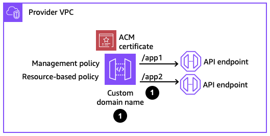
To use multi-level prefixes for custom domains with REST API Gateway, you need the Terraform module for API Gateway v2.
resource "aws_api_gateway_rest_api" "apigw" {
   name = "${var.environment}-${var.api_name}"
   body = templatefile(
     local.oasFilePath,
     {
       vpc_link_id = var.vpc_link_id
       authorizer_uri = var.authorizer_uri
       authorizer_credentials = var.authorizer_credentials
     }
  )
  description = "API Gateway for ${var.api_name}"
  endpoint_configuration {
    types = ["REGIONAL"]
  }

   # Default endpoint needs to be disabled if CloudFront is used as entry point to API Gateway
  disable_execute_api_endpoint = true
  tags = local.tags
  }

  # Use apigatewayv2 in order to have multi level base path ex. /v1/service_name
  resource "aws_apigatewayv2_api_mapping" "this" {
     domain_name = var.domain_name
    api_id = aws_api_gateway_rest_api.apigw.id
    stage = aws_api_gateway_stage.apigw.stage_name
    api_mapping_key = var.api_mapping_path
  }
Simplify API security with automation
Maya’s Unified API Gateway implements a robust, multi-layered security strategy. This approach helps ensure comprehensive protection from external threats and enforces stringent access control policies.
AWS WAF inspects and filters incoming traffic to protect against common web exploits, including OWASP Top 10, such as SQL injection and cross-site scripting attacks. A combination of custom and managed rule sets blocks malicious requests and enforces security policies. AWS Shield Advanced mitigates distributed denial of service (DDoS) attacks and provides 24/7 access to the AWS Shield Response Team (SRT) for expert support during attack events. This helps ensure high availability and resiliency.
API Gateway is integrated with a Lambda authorizer for authentication and authorization. The custom function implements fine-grained access control based on several factors such as identity, roles, and scopes.
To help ensure the consistency and integrity of the API configurations, all updates and deployments are strictly managed through an automated infrastructure-as-code (IaC) pipeline. This helps eliminate the risk of unauthorized or accidental manual changes to the API Gateway and any underlying infrastructure. The IaC pipeline makes sure that all API configurations, including security settings, are deployed through a controlled and auditable process. This prevents configuration drift and makes sure that security policies are consistently applied across all APIs. This also means that all changes are subject to code reviews and version control, adding another layer of security and traceability.
End-to-end visibility with observability
Maya’s Unified API Gateway prioritizes comprehensive observability to proactively monitor API performance, identify potential issues, and provide a seamless user experience. It uses a combination of AWS services and integrated tools to achieve this.
Amazon CloudWatch is used to monitor key performance metrics, including latency, error rates, and requests counts. CloudWatch provides real-time insights into the health and performance of APIs. Alerts on P95 and P99 values help identify and address performance bottlenecks, ensuring responsiveness.
CloudWatch metrics are streamed to Dynatrace, an application performance monitoring (APM) tool. The centralized view helps correlate data from various sources, create custom dashboards, and configure intelligent alerts based on predefined thresholds.
To help ensure complete visibility into API activity, the Lambda authorizer and API Gateway access logs are centralized in Splunk. This provides a comprehensive audit trail to track authentication and authorization events, identify security incidents, and troubleshoot API requests. Headers generated after authentication and authorization are done are passed down to the backend services for proper log correlation.
Future roadmap
The Unified API Gateway will continue to evolve to meet the growing needs of the organization and its partners and customers. The following are the key future enhancements that will further streamline API management, improve the developer experience, and enhance security.
Integration with the internal developer portal: This will provide a self-service UI for bootstrapping new APIs from scratch and further empower developers. This will also simplify documentation and discovery by cataloging all APIs
A modular, extension-based design for enhanced processing: This will introduce custom processing of requests in-line in the gateway account before integrating with backend services. Examples include digital signature verification, message transformation, and custom business logic. A modular design will offer a flexible and scalable way to enhance the functionality of Maya’s APIs without modifying backend services.
Bring your own (BYO) authorizer: Support a wider range of identity providers and authentication protocols, providing greater flexibility and control over API access.
Centralizing schema validation: Moving schema validation to API Gateway to bring consistency and improve the robustness and security of APIs by preventing malformed or malicious requests from being processed.
API monetization: Create new revenue streams by adding support for usage-based billing, tiered pricing, and subscription models.
Conclusion
This post has described the creation of Maya’s robust API management and governance solution, using a combination of native AWS services and powerful partner tools such as Terraform and Dynatrace. We’ve demonstrated how this Unified API Gateway has streamlined and automated core API processes, transforming Maya’s previously fragmented infrastructure into a secure and observable ecosystem. By establishing clear guardrails, the API solution team empowers developers to rapidly deploy APIs while maintaining consistent standards.
With the recent implementation of this solution across more teams, Maya is focused on defining and tracking key performance indicators (KPIs). We anticipate measuring critical metrics such as API onboarding efficiency, developer experience, API latency, and security incident rates. These insights will serve as a foundation for continuous improvement and optimization, ensuring the solution’s sustained effectiveness and evolution.
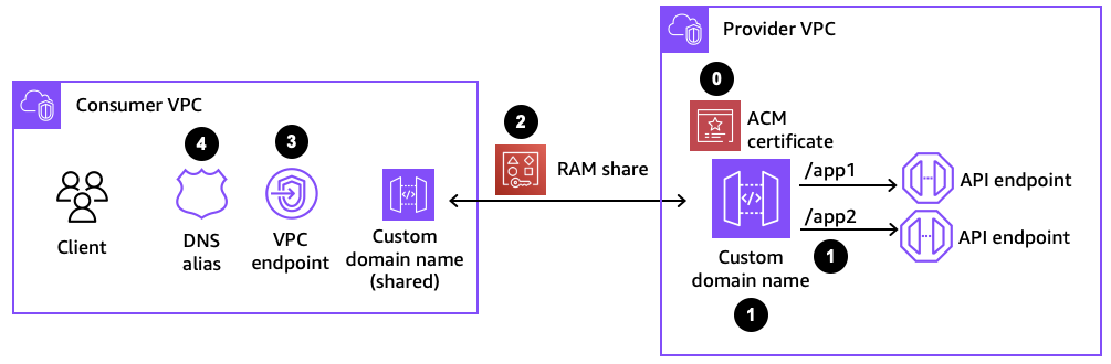
Amazon API Gateway can provide a single-entry point for all incoming API requests for Hybrid Workloads. You can use API Gateway to expose your resources in Amazon Virtual Private Cloud (VPC) and on-premises as REST APIs to external consumers. It provides a layer of abstraction between the API consumers and the backend services, allowing for centralized control. Routing all traffic through the API Gateway lets builders centrally enforce authentication, authorization, rate limiting, and other security features. This blog post describes how to configure API Gateway as an entry point to your on-premises resources.
Hybrid workloads can take advantage of API Gateway acting as single-entry point and provide a consistent interface for cloud and on-premises private API’s. You can connect API Gateway to resources within your private network through VPC link.
Figure 1 – private connectivity through VPC link
When private resources are located in different VPCs or AWS accounts, you can use AWS Transit Gateway or VPC peering to connect them.
Figure 2 – private connectivity through AWS Transit Gateway
You can also connect API Gateway to private resources hosted in your on-premises network.
Prerequisite
This blog assumes that you have an on-premises server hosting an API. Private connectivity between your AWS VPC and on-premises is needed, follow implementation step 1 for establishing private connectivity.
Solution overview
Figure 3 illustrates how to connect API Gateway’s REST API to on-premises application. The following steps detail the setup process.
Figure 3 – REST API architecture diagram for On-Premise applications
Implementation
The proposed solution can be implemented in six major steps:
Step 1. Enable VPC communication with on-premises network Step 2. Setup Network Load Balancer for private integration with API gateway Step 3. Create the VPC link Step 4. Configure the API Gateway Step 5. Create integration with VPC link Step 6. Deploy the API
Step 1. Enable VPC communication with on-premises network
In this step we setup connectivity between Amazon VPC and on-premises network
Step 2. Setup Network Load Balancer for private integration with API gateway
In this step we setup Network Load Balancer required for private integration with API Gateway
Sign in to the AWS Management Console and open the Amazon EC2 console at Amazon EC2 console
Configure target group for your Network Load Balancer. Target group is used for request routing to your application. You will register on-premises server IPs in the target group. The load balancer checks the health of targets in this target group using the health check settings defined for the target group.
In the navigation pane, under Load Balancing, choose Target Groups.
Choose Create target group.
Keep the target type as IP addresses
For Target group name, enter a name for the new target group.
For Protocol, choose TCP, and for Port, choose the port where your application is running.
For VPC, select the VPC created in PART A.
For Health checks, keep the default settings.
Choose Next.
On the Register targets page, complete the following steps:
Select the network as Other private IP address and Availability Zone as All
Enter the IP addresses and port of the on-premises application, and then choose Include as pending below.
Choose Create target group.
Figure 4 – Amazon EC2 console create target group
Configure your load balancer and listener To create a Network Load Balancer, you must first provide basic configuration information for your load balancer, such as a name, scheme, and IP address type. Then provide information about your network, and one or more listeners. A listener is a process that checks for connection requests. It is configured with a protocol and a port for connections from clients to the load balancer.
For Load balancer name, enter a name for your load balancer.
For Scheme and IP address type, keep the default values.
For Network mapping, select the VPC that was previously created. Select one subnet each in at least two availability zones for high availability. By default, AWS assigns an IPv4 address to each load balancer node from the subnet for its Availability Zone.
For Security groups, you will have a default security group associated for your VPC. Remove the default security group as it is not required for this setup.Review your configuration, and choose Create load balancer.
For Listeners and routing, select the protocol as TCP and port of your application, and select the target group from the list. This configures a listener that accepts TCP traffic on port that you specify and forwards traffic to the selected target group by default.
Review your configuration, and choose Create load balancer.
Turn off security group evaluation for PrivateLink for your Network Load Balancer.
Go to your Network Load Balancer.
Select the Security tab.
Choose Edit.
Clear “Enforce inbound rules on PrivateLink traffic”.
Save changes
Figure 6 – Amazon EC2 console -> Load Balancers -> Security; turn off security group evaluation
Step 3. Create the VPC Link
In this step we create a VPC link to connect your API and your Network Load Balancer. After you create a VPC link, you create private integrations to route traffic from your API to resources in your VPC through your VPC link and Network Load Balancer. To create VPC link, you need to do the following:
For Description(optional), provide a description for your API.
For API endpoint type, select regional from the drop-down option.
Choose Create API.
Figure 8 – Amazon API Gateway console create REST API
Step 5. Create integration with VPC link
In this step we integrate the VPC link with the API created in the previous step.
Create Resource
From API Gateway console select Create resource
Under Resource details, specify the resource path and resource name
Choose Create resource
Figure 9 – Amazon API Gateway console create resource for VPC link integration
Create Method
From API Gateway console select Create method.
For Method type, select the desired method.
For Integration type, select VPC link.
Turn on VPC proxy integration.
For HTTP method, select desired method.
For VPC link, select the VPC link from the dropdown menu that was created in the previous steps.
For Endpoint URL, enter a URL for the NLB created in the previous steps along with the port number. For eg: http://nlb-api-integration-xxxxxxxxxxxxxxxx.elb.us-east-1.amazonaws.com:80/on-prem. Assuming the endpoint is going to retrieve /on-prem resource.
Choose Create method. With the proxy integration, the API is ready for deployment. Otherwise, you need to proceed to set up appropriate method responses and integration responses.
Figure 10 – Amazon API Gateway console create method and provide method details
Figure 11 – Amazon API Gateway console create method and provide method details
Step 6. Deploy the API
Final step is to deploy the API. You can do that by using the following steps:
Choose Deploy API
For Stage, select New stage.
For Stage name, enter a stage name.
For Description(optional), enter a description.
Choose Deploy
Figure 12 – Amazon API Gateway console deploy the created API
Security
Security is the top priority at AWS and operates on a shared responsibility model between AWS and its customers. When managing hybrid APIs, implementing robust security measures is essential since these APIs serve as critical gateways to sensitive data and services. For detailed guidance on securing your REST APIs using API Gateway, please consult our documentation
Cleanup
To prevent incurring additional charges, remove the resources that were created during this walkthrough
Open the API Gateway console.
Select the APIs you created and select delete.
Go to the VPC links in the navigation pane and select the VPC link created. Delete the VPC link.
Within the EC2 console, go to load balancers in the navigation pane and delete the target group and NLB.
Conclusion
This post demonstrates how to configure API Gateway as an entry point for your on-premises resources, providing a unified API interface for your clients.
You can read more about working with API Gateway in AWS documentation and use these capabilities to create architectures to suit your specific requirements. For more serverless learning resources, visit Serverless Land.
In this post, you learn how to use AWS serverless technologies, such as Amazon EventBridge and AWS Lambda, to build an integration between Quick Service Restaurants (QSRs) and online ordering and food delivery aggregators. These aggregators have taken off as an option to QSRs to expand their consumer base, enabling them with delivery options to help grow their businesses.
QSR overview
QSRs prioritize speedy and convenient service, offering a streamlined menu. To meet evolving consumer expectations, QSRs can use API integrations with third-party aggregators. This technological synergy enables QSRs to expand their capabilities, introducing diverse payment methods and incorporating delivery services. These features have become standard in this restaurant segment.
Behind the scenes, the APIs are used to orchestrate the interaction between the aggregator and the QSR while having a consistent ordering and delivery experience.
QSR business objectives are:
Providing consistent ordering and delivery experiences
Offering personalized menu items
Retaining repeat customers
Reducing third-party delivery cancellation due to lack of delivery personalization options
This post starts with a simple architecture and adds components to solve architectural challenges.
Architecture
As a solutions architect, you’ve been approached by a thriving local restaurant business seeking technological solutions to fuel their expansion. Your task is to design an optimal integration architecture that aligns with their technical requirements, streamlines operations, and enhances customer experience.
At the core of this integration is Amazon API Gateway, which accepts the incoming orders from various delivery aggregators. The API Gateway becomes the front door, connecting the QSRs with the end customers for a streamlined and dynamic order processing system.
Driving the backend of this integration are Lambda functions. These functions validate orders and securely communicate with delivery aggregators. Lambda functions can scale dynamically based on-demand, and make sure of optimal resource usage and cost-effectiveness.
Order placement workflow
The following steps outline the serverless integration between API Gateway and Lambda functions, as shown in the following figure:
Customers can place orders either through food delivery aggregators or the business’s own ordering system.
The order request is sent to API Gateway.
This architecture works for small and simple integrations. To scale this architecture for high traffic, use asynchronous integration to reduce the coupling between API and Lambda function.
Order routing workflow
The following steps outline a serverless integration where API Gateway connects to Lambda functions through Amazon EventBridge as the event routing service, as shown in the following figure:
API Gateway receives the order request.
The API Gateway routes the customer’s order request to an EventBridge bus for processing.
EventBridge routes events (for example order status changes) to Lambda functions, making sure of resiliency during service disruptions. This eliminates manual error handling and keeps QSRs and aggregators synchronized.
EventBridge delivers the following essential capabilities:
EventBridge receives events triggered by various actions, such as new orders or menu updates.
It routes events to the relevant Lambda functions, initiating the appropriate actions.
EventBridge supports event replay, allowing recovery from Lambda deployment issues or function failures. This feature enables business continuity by storing events during service disruptions and automatically resuming processing when the system stabilizes.
To maintain order history and enable fast data retrieval, the system needs a highly performant database. Amazon DynamoDB, a serverless NoSQL database service, meets these requirements by efficiently storing and managing order information and metadata. The order processing Lambda function interacts with DynamoDB to persist order details. This approach enables asynchronous processing of the stored data by other backend processes. The database solution provides the scalability and responsiveness needed to handle growing order volumes while maintaining consistent performance, separating order intake from subsequent processing steps.
Order processing workflow
The following steps outline the order processing workflow, as shown in the following figure:
The order processing Lambda function validates the order and updates the DynamoDB database with the new order details.
The function publishes error events to EventBridge, enabling downstream processing for error handling and retry logic. These events can trigger more Lambda functions designed to manage specific error scenarios and recovery processes.
EventBridge implementation patterns: single or dual bus approaches
EventBridge offers multiple approaches for event bus topology. Architects can choose to either use a single event bus with distinct event patterns based on order status or implement a multi-bus strategy.
The single-bus approach uses one event bus for all events with routing rule patterns based on order status. For example, rules would match specific statuses (for example “new” or “processed”) to trigger appropriate Lambda functions. Although it is architecturally simple, it needs careful management of the event schema to avoid potential errors. However, a single-bus approach requires careful handling to prevent recursive processing, where messages trigger additional messages in an endless loop.
Alternatively, the multi-bus method, separating order placement and processing across different buses, effectively prevents loops and recursion issues. This approach provides better separation of transactions, albeit with a slightly more complex setup.
EventBridge can directly target external services using the API destination option, eliminating the need for Lambda functions for third party integrations.
Orchestrating order processing
In complex order processing systems for QSRs, managing multiple interdependent Lambda functions can become challenging, potentially leading to intricate code and difficult-to-maintain architectures. To address this, AWS Step Functions can be introduced as an orchestration layer.
Step Functions acts as a central coordinator for the business logic needed in QSR order flows. This service manages the progression of activities in the order processing workflow, thereby efficiently coordinating tasks such as kitchen preparation and delivery logistics. Defining and managing complex workflows allows Step Functions to optimize the overall efficiency of QSR operations, providing a structured and adaptable solution. This orchestration enhances the restaurant’s ability to handle dynamic processing, achieving a smooth and responsive integration with delivery services while streamlining the underlying architecture.
The following steps outline the orchestration of order processing, as shown in the following figure:
Order processing trigger respective Lambda function, which updates the order data in the DynamoDB database.
The updated order is made available for subsequent Lambda functions that process more business logic being performed by further Lambda functions.
In a multi-bus EventBridge architecture, the process flows are as follows:
The first EventBridge bus receives the initial order event and routes it to a Step Functions workflow.
The Step Functions workflow orchestrates the order processing, coordinating various tasks and checks.
Upon completion, the Step Functions workflow emits an event with the processing results to the second EventBridge bus.
Based on the output from the Step Function workflow, this second bus contains a rule that triggers the Aggregator API as an API destination.
User engagement workflow
When a customer places an order, there must be a way to confirm or notify them when the order is ready. For this purpose, you can use AWS End User Messaging services to push notifications for order completion and new offers to customers.
Amazon Personalize can analyze historical order data to enhance the user experience through personalized recommendations, such as optimal delivery times, preferred menu items, and tailored promotions based on individual ordering patterns.
Conclusion
This post showed how to use AWS serverless services to build a platform for your order processing without worrying about managing underlying infrastructure. The serverless services included were Amazon API Gateway, AWS Lambda, Amazon EventBridge, AWS Step Functions, AWS End User Messaging, and Amazon Personalize.
This post is a brief introduction to event-driven architectures focused on integrations of internal ordering systems with delivery aggregators and third-party ordering platforms. This can help expand the user base, and it has been a key factor in the growth of many QSRs. Making the ordering, take-out, and delivery experience more efficient translates to revenue growth, reduction of order abandonment, as well as increased recurrent customer retention and brand loyalty.
AWS Summit season starts this week! These free events are now rolling out worldwide, bringing our cloud computing community together to connect, collaborate, and learn. Whether you prefer joining us online or in-person, these gatherings offer valuable opportunities to expand your AWS knowledge. I will be attending the Summit in Paris this week, the biggest cloud conference in France, and the London Summit at the end of the month. We will have a small podcast recording studio where I will interview French and British customers to produce new episodes for the AWS Developers Podcast and le podcast AWS en .
Register today!
But for now, let’s look at last week’s new announcements.
Last week’s launches At KubeCon London, we introduced the EKS Community Add-Ons Catalog, making it simpler for Kubernetes users to enhance their Amazon EKS clusters with powerful open-source tools. This catalog streamlines the installation of essential add-ons like metrics-server, kube-state-metrics, prometheus-node-exporter, cert-manager, and external-dns. By integrating these community-driven add-ons directly into the EKS console and AWS command line interface (AWS CLI), customers can reduce operational complexity and accelerate deployment while maintaining flexibility and security. This launch reflects AWS’s commitment to the Kubernetes community, providing seamless access to trusted open-source solutions without the overhead of manual installation and maintenance.
Amazon Q Developer now integrates with Amazon OpenSearch Service to enhance operational analytics by enabling natural language exploration and AI-assisted data visualization. This integration simplifies the process of querying and visualizing operational data, reducing the learning curve associated with traditional query languages and tools. During incident responses, Amazon Q Developer offers contextual summaries and insights directly within the alerts interface, facilitating quicker analysis and resolution. This advancement allows engineers to focus more on innovation by streamlining troubleshooting processes and improving monitoring infrastructure.
Amazon SES has introduced support for email attachments in its v2 APIs, enabling users to include files like PDFs and images directly in their emails without manually constructing MIME messages. This enhancement simplifies the process of sending rich email content and reduces implementation complexity. Amazon Simple Email Service (Amazon SES) supports attachments in all AWS Regions where the service is available.
Other AWS events Check your calendar and sign up for upcoming AWS events.
AWS GenAI Lofts are collaborative spaces and immersive experiences that showcase AWS expertise in cloud computing and AI. They provide startups and developers with hands-on access to AI products and services, exclusive sessions with industry leaders, and valuable networking opportunities with investors and peers. Find a GenAI Loft location near you and don’t forget to register.
(This survey is hosted by an external company. AWS handles your information as described in the AWS Privacy Notice. AWS will own the data gathered via this survey and will not share the information collected with survey respondents.)
Today, we are launching IPv6 support for Amazon API Gateway across all endpoint types, custom domains, and management APIs, in all commercial and AWS GovCloud (US) Regions. You can now configure REST, HTTP, and WebSocket APIs, and custom domains, to accept calls from IPv6 clients alongside the existing IPv4 support. You can also call API Gateway management APIs from dual-stack (IPv6 and IPv4) clients. As organizations globally confront growing IPv4 address scarcity and increasing costs, implementing IPv6 becomes critical for future-proofing network infrastructure. This dual-stack approach helps organizations maintain future network compatibility and expand global reach. To learn more about dualstack in the Amazon Web Services (AWS) environment, see the IPv6 on AWS documentation.
When creating a new API or domain name in the console, select IPv4 only or dualstack (IPv4 and IPv6) for the IP address type.
As shown in the following image, you can select the dualstack option when creating a new REST API. For custom domain names, you can similarly configure dualstack as shown in the next image.
If you need to revert to IPv4-only for any reason, you can modify the IP address type setting, with no need to redeploy your API for the update to take effect.
REST APIs of all endpoint types (EDGE, REGIONAL and PRIVATE) support dualstack. Private REST APIs only support dualstack configuration.
AWS CDK
With AWS CDK, start by configuring a dual-stack REST API and domain name.
const api = new apigateway.RestApi(this, "Api", {
  restApiName: "MyDualStackAPI",
  endpointConfiguration: {ipAddressType: "dualstack"}
});

const domain_name = new apigateway.DomainName(this, "DomainName", {
  regionalCertificateArn: 'arn:aws:acm:us-east-1:111122223333:certificate/a1b2c3d4-5678-90ab',
  domainName: 'dualstack.example.com',
  endpointConfiguration: {
    types: ['Regional'],
    ipAddressType: 'dualstack'
  },
  securityPolicy: 'TLS_1_2'
});

const basepathmapping = new apigateway.BasePathMapping(this, "BasePathMapping", {
  domainName: domain_name,
  restApi: api
});
IPv6 Source IP and authorization
When your API begins receiving IPv6 traffic, client source IPs will be in IPv6 format. If you use resource policies, Lambda authorizers, or AWS Identity and Access Management (IAM) policies that reference source IP addresses, make sure they’re updated to accommodate IPv6 address formats.
For example, to permit traffic from a specific IPv6 range in a resource policy.
API Gateway dual-stack support helps manage IPv4 address scarcity and costs, comply with government and industry mandates, and prepare for the future of networking. The dualstack implementation provides a smooth transition path by supporting both IPv4 and IPv6 clients simultaneously.
To get started with API Gateway dual-stack support, visit the Amazon API Gateway documentation. You can configure dualstack for new APIs or update existing APIs with minimal configuration changes.
Special thanks to Ellie Frank (elliesf), Anjali Gola (anjaligl), and Pranika Kakkar (pranika) for providing resources, answering questions, and offering valuable feedback during the writing process. This blog post was made possible through the collaborative support of the service and product management teams.
(This survey is hosted by an external company. AWS handles your information as described in the AWS Privacy Notice. AWS will own the data gathered via this survey and will not share the information collected with survey respondents.)
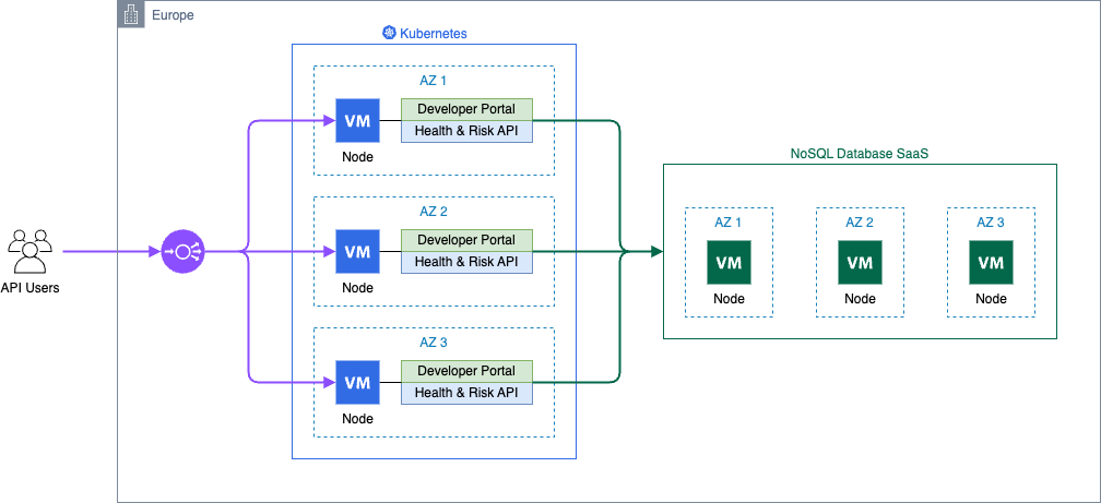
dacadoo is a global Swiss-based technology company that develops solutions for digital health engagement and health risk quantification. Their products include a software-as-a-service (SaaS)-based digital health engagement platform that uses behavioral science, AI, and gamification to help end users improve their health outcomes.
To transform a virtual machine–based API service into a globally redundant, scalable health score and risk calculation solution dacadoo chose Amazon Web Services (AWS) technology. The service handles highly sensitive health data from a global customer base and must comply with regional regulations.
The result is a cost reduction of 78% and an infrastructure maintenance effort of less than an hour per year , allowing dacadoo to deliver and operate more AWS infrastructure without scaling its site reliability engineering (SRE) team, thanks to a high level of automation and an agile mindset.
In this post, we walk you step-by-step through dacadoo’s journey of embracing managed services, highlighting their architectural decisions as we go.
Background
The solution architecture went through a three-stage journey:
Incubation – Single virtual machine on premises with disaster recovery (DR) in Switzerland
Global and scalable – Multiple global Kubernetes clusters
Operational excellence – Fully serverless and geo-redundant on AWS
Stage 1: Incubation with a virtual machine
After years of scientific research and development, the service was launched, running on a single on-premises virtual machine that used hypervisor technology to provide disaster recovery (DR). However, it had no high availability (HA) capability and it required manual recovery.
The application serving the API requests and the NoSQL database were both running on the same host. Software deployment and operating system maintenance were performed manually using Secure Shell (SSH)—a typical low-automation setup that also included downtime.
The following architecture diagram shows a virtual machine encompassing the monolithic application and its database.
Challenges
A single virtual machine was quick to set up and inexpensive to operate, but it had considerable shortcomings. The health API was only available in Switzerland, infrastructure maintenance was performed manually, and software deployment was handled manually. Additionally, database backups were done using virtual machine snapshots, uptime monitoring only, and testing was conducted on the developer workstation.
Stage 2: Global and scalable with Kubernetes
At that time, dacadoo made a strategic decision to heavily invest in Kubernetes for managing containerized workloads on a global scale. As part of this technology rollout, the health score and risk service were migrated to Kubernetes.
Due to the geographically distributed customer base and low latency requirements, three Kubernetes clusters were deployed, one on each continent. The NoSQL database was hosted in proximity to the workload to reduce service latency and keep the migration effort low.
To reduce the operational maintenance, the NoSQL database was integrated as a SaaS offering, and monitoring was centralized using Datadog.
All cloud infrastructure was provisioned exclusively with Terraform, covering the Kubernetes cluster, NoSQL database , and integration with GitLab and Datadog.
dacadoo containerized the API service and used Gitlab continuous integration and continuous deployment (CI/CD) pipelines to deploy multiple environments and clusters on a global hyperscaler.
In retrospect, this was a typical replatform modernization project from virtual machine to Kubernetes, with a high level of automation and a SaaS-first approach.
The following diagram is the architecture for the container solution with managed NoSQL database.
Challenges
The service faced several challenges, including increased costs from deploying three regional Kubernetes clusters across three environments, resulting in 27 cluster nodes and additional expenses from managing NoSQL database SaaS instances for each cluster. The complexity of CI/CD pipelines for multi-environment multi-cluster deployments added to the difficulty. Significant operational effort was required to keep infrastructure and Kubernetes components up to date.
Stage 3: Operational excellence with serverless
The Kubernetes-based architecture met the requirements, but some features in the dacadoo API service backlog needed to fit better with the application architecture at the time.
This was the right moment to take a holistic view of the infrastructure and software architecture and refactor the solution according to the latest AWS technologies and best practices, the next frontier for dacadoo’s engineering team.
Solution requirements
Requirements for the solution refactoring were as follows:
Keep the functionality of the API unmodified
Constrain data processing to a region of choice for compliance with local data protection laws
Avoid weekly patch cycles by exclusively using managed serverless services
Reduce costs by choosing services with a pay-as-you-go billing model
Delegate authentication to a dedicated service
Use an established web framework with an extensive ecosystem
Refactoring the apps
The API service has two components: a developer portal and the health score and risk calculations API. The database is only required for API keys, algorithm parameters, quotas, and usage statistics. Health data is processed regionally by the compute layer but not persisted, opening the door for a distributed database: Amazon DynamoDB global tables is the perfect fit for the solution. Writes are distributed to all connected Regions, whereas reads are local, providing low latency for complying with dacadoo service level agreements (SLAs).
The developer portal is a web UI with API documentation and API key management features. AWS Lambda is a great fit because it scales automatically and has a pay-per-request billing model.
The health and risk API uses algorithms implemented in the C programming language for short bursting, compute-intense simulations. These calls are wrapped by a REST API using the Python FastAPI framework. These characteristics make AWS Lambda a great fit.
Serverless architecture
HTTP requests are routed to the Lambda functions using Amazon API Gateway with AWS WAF for protection from malicious requests and attacks. Static assets are served from an Amazon Simple Storage Service (Amazon S3) bucket through API Gateway. The additional features of Amazon CloudFront aren’t required, and Amazon S3 reduces the complexity.
Amazon Route 53 provides a powerful feature known as latency-based routing, which allows it to direct DNS queries to the endpoint that offers the lowest latency for the requester.
This feature provides Regional high availability for API users without data processing location requirements. Alternatively, the user can call specific Regional endpoints to make sure requests are processed in the desired Region.
API authorization is HTTP header-based and is performed in the application with data stored in Amazon DynamoDB.
The following diagram is the architecture for a geo-redundant fully serverless solution.
With a dacadoo SRE team proficient in Python, they opted for Pulumi for its advanced features such as programming language flow control constructs, powerful configuration capabilities, and multi-cloud support.
For continuous integration, GitLab CI compiles the algorithm library, tests the FastAPI applications and packages everything. The application deployment is just an update of the AWS Lambda, a simple and reliable workflow.
Summary
The solution evolved from a managed infrastructure setup, where the customer held most of the responsibility, to an AWS managed service architecture.
Infrastructure provisioning evolved from manual, error-prone processes to powerful code-driven workflows in Pulumi. The SRE needed to enhance their software engineering skills to adopt Pulumi, transitioning from configuration-based approaches to designing and maintaining an infrastructure code base using object-oriented Python. This was part of dacadoo’s investment in the SRE team and broader modernization efforts. The serverless architecture enabled a GitOps engineering culture focused on productivity.
The transformation maximized scalability and availability while reducing costs and operational effort:
Virtual machine
Scalability: Low
Availability: Best effort
Infrastructure costs: Low
Maintenance effort: High
Kubernetes
Scalability: High
Availability: 99.95%
Infrastructure costs: High
Maintenance effort: Medium
Serverless
Scalability: Very high
Availability: 99.999% (with failover to another AWS Region)
Infrastructure costs: Low
Maintenance effort: Very low
The global redundancy elevates availability to an impressive 99.999% while keeping the costs low.
Conclusion
Migrating from a virtual machine to Kubernetes and ultimately to AWS Lambda demonstrates the progression of cloud engineering toward enhanced efficiency and scalability.
Each step in this journey reduced the complexity of managing resources while increasing flexibility and automation. Transitioning dacadoo’s API service to a fully serverless, geo-redundant architecture not only advanced the platform but also upskilled engineers, maintained a lean SRE team, and kept infrastructure costs low. Get started with your own AWS serverless solution.
This post is authored by Anton Aleksandrov, Principal Solution Architect, AWS Serverless and Daniel Abib, Senior Specialist Solutions Architect, AWS
Serverless application developers may commonly encounter scenarios where they need to transport large payloads, especially when building modern cloud applications that need rich data. Examples include analytics services with detailed reports, e-commerce platforms with extensive product catalogs, healthcare applications transmitting patient records, or financial services aggregating transactional data.
Many serverless services have a well-defined maximum payload size. For example, AWS Lambda maximum request/response payload size is 6 MB, and Amazon Simple Queue Service (Amazon SQS) and Amazon EventBridge maximum message size is 256 KB. In this post, you will learn how to use data compression techniques to reduce your network footprint and transport larger payloads under existing constraints.
Overview
Cloud applications evolve continuously and need to be adjusted frequently for new requirements, such as new business features or new Service Level Objectives (SLO) for higher throughput and lower latency. As new use cases and data patterns are added, it is common to see request and response payload sizes increase. At some point, you might hit the maximum service payload size limits, such as 6 MB for synchronous Lambda function invokes, 10 MB for Amazon API Gateway, and 256 KB for Amazon SQS, EventBridge, and asynchronous Lambda invokes.
There are several techniques you can apply when dealing with large payloads. If your payloads are tens of MBs or more, or you need to transport large binary objects with API Gateway, you can store the payload on Amazon Simple Storage Service (Amazon S3) and use pre-signed URLs for clients to directly upload and download from S3.
Figure 1. A sample of architecture for handling large payloads
Lambda function URLs response streaming supports up to 20 MB responses. For handling large messages with services such as SQS or EventBridge, you can store the message in S3 and pass a reference. The downstream consumer will use the reference to download the message directly from S3. One common characteristic of these techniques is that they introduce architectural complexity and may necessitate modifications to your existing solution architecture and data flow patterns.
Furthermore, as your payloads grow in size, you will see increased data transfer costs, especially if your solution is transporting data through Amazon Virtual Private Cloud (VPC)NAT Gateways, VPC endpoints, or sending data across AWS Regions. For example, it is common for VPC-based solutions to have Lambda functions in their architecture. A container running on Amazon Elastic Kubernetes Service (Amazon EKS) might need to invoke a Lambda function, or a VPC-attached Lambda function might need to reach out to the public internet.
Figure 2. Examples of using virtual network appliances with serverless applications
Both NAT Gateway and VPC Endpoint are billed per GB of data processed, which makes data compression a valuable optimization technique. Go to NAT Gateway pricing and VPC Endpoint pricing for details.
The following sections explore data compression techniques and demonstrate how to apply them in your serverless applications. You can learn how to send larger payloads within the existing payload size boundaries and reduce your network footprint without significant architectural changes. This post discusses compression techniques in the context of Lambda and API Gateway, but the same principles can be applied to other services, such as SQS, EventBridge, and AWS AppSync. Understanding compression concepts better equips you to optimize your application’s data-handling capabilities.
What is data compression?
Compression is a widely used approach to reduce data size in order to improve cost-effectiveness and performance for data storage and transmission. Many tools and frameworks incorporate data compression techniques, such as gzip or zstd. It is thoroughly documented in the official IANA specification and IETF RFC 9110. Browsers such as Chrome and Firefox, HTTP toolkits such as curl and Postman, and runtimes such as Node.js and Python natively handle compression, often without user involvement.
Consider HTTP protocol. When a client wants to send a compressed payload, it specifies it in the Content-Type header. To receive a compressed response, the client specifies supported compression methods in the Accept-Encoding request header.
The server compresses the response payload using one of the supported methods and uses the Content-Encoding response header to indicate the method to the client.
This mechanism can accelerate client-server communications by reducing the number of bytes transmitted over the network. Compression efficiency depends on the data type. Text-based formats like JSON, XML, HTML, and YAML compress well, while binary data such as PDF and JPEG generally compress less effectively.
Data compression with API Gateway
API Gateway provides built-in compression support. Use the minimumCompressionSize configuration to set the smallest payload size to compress automatically. The value can be between 0 bytes to 10 MB. Compressing very small payloads might actually increase the final payload size, and you should always test with your real payload patterns to determine the optimal threshold.
Figure 5. Handling data compression in API Gateway
API Gateway enables clients to interact with your API using compressed payloads through supported content encodings. The compression mechanism works bi-directionally. For JSON payloads, API Gateway seamlessly handles compression and decompression, maintaining compatibility with mapping templates. It decompresses incoming payloads before applying request mapping templates and compresses outgoing responses after applying response mapping templates. This automated compression optimizes data transfer:
When sending compressed data, clients supply the appropriate Content-Encoding header. API Gateway handles the decompression and applies configured mapping templates before forwarding the request to the integration.
When API Gateway receives an integration response and compression is enabled, it compresses the response payload and returns it to the client, provided that the client has included a matching Accept-Encoding header.
A sample test using the compression technique with API Gateway and JSON payload yielded the following results.
Compressing data resulted in 78% network footprint reduction and improved latency by 110 ms.
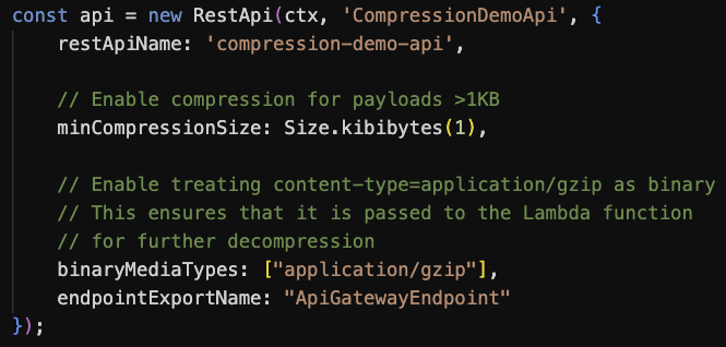
This configuration-based technique uses the API Gateway native compression. However, payloads are decompressed before being delivered to downstream integrations, thus they still remain subject to Lambda’s 6 MB max payload size. To address this, you can configure binaryMediaTypes in the API Gateway to pass compressed payloads to Lambda directly, enabling the function to handle decompression.
Figure 6. CDK code to configure API Gateway for data compression and binary data passthrough
Handling compressed data in Lambda functions
The Lambda Invoke API supports payloads in plain-text formats, such as JSON. The maximum payload size is 6 MB for synchronous invocations and 256 KB for asynchronous. Although the Invoke API supports uncompressed text-based payloads, you can introduce data compression in your function code and use API Gateway or Function URLs to facilitate content conversion, as illustrated in the following figure.
Figure 7. Transporting compressed payloads in a serverless applications
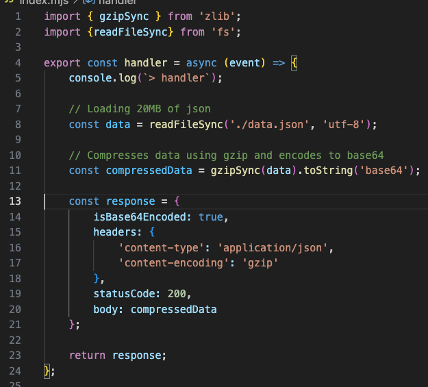
Handling data compression in your Lambda function code can be done through libraries commonly embedded in the runtime. The following code snippet shows the compressing response payload using Node.js. Similar techniques can be applied to other runtimes.
Figure 8. Sample code implementing response payload compression in a Lambda function
Line 1: Import gzip functionality from the zlib module.
Lines 11: Compress and Base64-encode data. Gzip compression, similar to many other compression methods, produces a binary stream. Base64 encoding converts it to the text-based format expected by the Lambda service
Lines 13-21: Response object is created with isBase64Encoded=true and response headers telling the client that the response is a gzip-encoded JSON object.
The following screenshot shows the result: 20 MB uncompressed JSON returned from a Lambda function as a 2.5 MB compressed response body. Network footprint reduced by over 80%.
Figure 9. A screenshot from Postman showing the original and compressed payload size
Using this technique, you can reduce your network footprint and transport payload sizes several times higher than the Lambda maximum payload size.
Using Function URLs with compressed payloads
Transporting compressed payloads through Lambda Function URLs doesn’t necessitate any extra configuration. For handler responses, your code needs to compress and Base64-encode the data as shown in the preceding figure. For invocation requests, the Function URL endpoint recognizes the incoming compressed payload as binary and passes it to your handler as a Base64 encoded string in the event body.
Figure 10. Sample code implementing request payload decompression in a Lambda function
Trade-offs and testing results
Compressing data in function code is a CPU-intensive activity, potentially increasing invocation duration and, as a result, function cost. This, however, can be balanced by the benefits of data compression. As you’ve seen in previous sections, while compressing data adds compute latency, transporting smaller payloads over the network reduces network latency. The following section summarizes a series of tests performed to estimate the impact of data compression on Lambda function invocation duration, Lambda function invocation cost, and data transfer savings with both NAT Gateway and VPC Endpoint. The tests were performed with several assumptions and randomly generated JSON data. You can see full testing results in the sample GitHub.com repo.
Test results demonstrated that the impact on function latency and cost primarily depends on two key factors: payload size and allocated memory (which determines vCPU capacity). Using a Node.js runtime with ARM architecture as an example, compressing a 1 MB JSON object in a function with 1 GB of allocated memory resulted in 124 ms of added processing time on average. For 10 million invocations, this extra processing time adds approximately $16. At the same time, the compression yielded a 70% reduction in payload size. With the same number of invocations, this translates to approximately $300 in savings when using NAT Gateway and $70 in savings when using VPC Endpoints (depending on the number of Availability Zones (AZs)).
AWS Service pricing is updated regularly, you should always consult the respective pricing pages for the latest information. Moreover, you should conduct your own performance and cost estimates using payloads that represent your workloads. Compression effectiveness varies significantly depending on the data type: payloads with low compression rates might not benefit from this technique.
Sample application
Follow the instructions in this GitHub repository to provision the sample in your AWS account. The project creates two Lambda functions to demonstrate receiving and returning compressed JSON using Function URLs and API Gateway.
The sample shows how to GET and POST JSON payloads using gzip compression to reduce the network footprint by over 80%.
Figure 11. A screenshot from Postman showing the original and compressed payload size
Conclusion
Data compression enables larger payload transfers and reduces network footprint. It can help to lower network latencies and optimize data transfer costs. When implementing compression within Lambda functions, it is important to consider its CPU-bound nature, which may increase function duration and costs. You should always evaluate the added compute cost against potential data transfer savings to make sure the technique benefits your use case.
Compression is most effective for handling large text-based payloads and when a slight increase in compute latency balanced by reduced network latency is acceptable.
To learn more about Serverless architectures and asynchronous Lambda invocation patterns, see Serverless Land.
Enterprises face many challenges when they build and manage application programming interfaces (APIs). These challenges include security controls, version management, traffic control, and usage analytics. As digital businesses expand, a mature API management (APIM) solution is crucial for ensuring scalability, security, and operational efficiency.
This blog post shows how you can use Amazon API Gateway—along with AWS Lambda, Amazon DynamoDB, and other AWS services—to create a comprehensive and customizable APIM solution. This solution addresses the complex requirements of large enterprises managing APIs at scale.
Core features of APIM
API Management (APIM) centralizes the management and publishing of APIs for the entire enterprise, acting as a hub between clients, applications, and administrators on one side, and internal services, external systems, and large language models (LLMs) on the other, as shown in the following figure.
The key features of APIM include:
Security and governance
Authentication, authorization, rate limiting, and security policy enforcement.
Helps ensure APIs meet organizational or industry standards.
Monitoring and logging
Provides monitoring, alarms, and logging to track API performance and troubleshoot issues quickly.
Customization and transformation
Offers protocol and field transformations, plus orchestration and aggregation.
Makes it easier to integrate with different systems and meet various client needs.
API lifecycle management
Publishing, rollback, version control, and documentation.
Streamlines development and maintenance throughout the API lifecycle.
Developer and business tools
Portals for developers, business owners, and administrators to manage documentation, billing, and analytics.
Integration with LLMs
Specialized adapters, proxy configurations, and switching to integrate AI models seamlessly.
Flexible deployment options
Canary releases, pipeline automation, and other advanced release strategies.
Helps ensure stable, controlled API updates.
Unified management of multiple API gateways
API Gateway enforces resource limits of 300 resources per gateway, with a hard limit of 600. For enterprises that require more resources, managing multiple gateways individually can be time-consuming and error prone. APIM simplifies this by integrating API Gateway, Lambda, and DynamoDB; creating a centralized platform for managing APIs across multiple gateways. This integration streamlines the process, making it easier to scale and maintain APIs.
API lifecycle management
Managing API versions, publishing updates, and maintaining documentation often requires separate tools and manual processes, leading to inefficiencies. APIM centralizes these tasks in one portal, offering version control, publishing workflows, and rollback options. This streamlines the API lifecycle, ensuring consistency and reducing the chances for errors.
Enhanced security
Enterprises often need to implement different authentication strategies for various clients. These configurations typically require custom Lambda logic and database lookups, adding complexity and cost. APIM introduces configurable security policies that allow client-specific authentication without the need for additional custom code, reducing both complexity and operational overhead.
Customization and transformation
Enterprises frequently handle diverse client requests that involve different formats and protocols. Traditional API management approaches might struggle to support such variations. APIM allows for seamless protocol and field transformations, enabling integrations that meet a wide range of client requirements without additional development effort.
Developer portal
Developers need clear documentation, easy testing environments, and efficient API key management to work effectively. Traditional systems often lack these features, slowing down adoption. APIM provides a developer portal that consolidates API documentation, offers sandbox environments for testing, and simplifies API key management, reducing onboarding time and improving the developer experience.
Logging and monitoring
Log management is key to maintaining API performance, diagnosing issues, and gaining insights into usage. APIM uses API Gateway custom access logging, allowing teams to define logs based on business needs; whether creating separate CloudWatch metrics for each API path or exporting data to external platforms like ELK or Grafana.
Architecture overview
The APIM architecture, shown in the following figure, includes a management state (represented by numbers) and a runtime state (represented by letters). Both parts use a serverless paradigm.
Management state
The management state includes the following elements:
Administrator portal access: Administrators access the APIM solution through a secured web portal.
API Requests to APIM Lambda: Requests from the administrator’s API go through API Gateway, which then invokes the APIM Lambda function. This function handles logic related to configuration changes and other administrative actions.
In the following example, we show you how the APIM Lambda function dynamically applies different middleware based on the route configuration. This approach allows for flexible handling of authentication, client access restrictions, and request/response transformations. Here’s a quick breakdown of the key elements:
// If the route requires OIDC (OpenID Connect) authentication,
// add the OIDC authentication middleware to the route.
if route.Auth == "OIDC" {
    r.Use(middleware.OidcAuthenticator)
}
// If the route configuration specifies a list of allowed clients
// and the list is not empty, add a middleware to restrict access
// to only the specified clients.
if route.Allow.Clients != nil && len(route.Allow.Clients) != 0 {
    r.Use(middleware.AllowClients(route.Allow.Clients, cfg.Clients))
}
// Remove specific headers injected by the API Gateway
// to reduce exposure of internal details to downstream systems.
r.Use(middleware.RemoveGatewayHeaders)

// Add additional middleware for handling outbound logic.
// This could include retries, logging, or other outbound-specific functionality.
r.Use(outboundMiddlewares)
// Dynamically constructs and applies a chain of middlewares
// based on the outbound configuration associated with the current request.
func outboundMiddlewares(next http.Handler) http.Handler {
    return http.HandlerFunc(func(w http.ResponseWriter, r *http.Request) {
        // Retrieve the outbound configuration from the request context.
        outbound, _ := r.Context().Value(selectedOutboundContext).(config.Outbound)

        // Initialize a slice to store the middlewares to be applied.
        middlewares := []func(http.Handler) http.Handler{}

        // Middleware to rewrite the HTTP request based on the outbound configuration.
        middlewares = append(middlewares, middleware.ProxyRequestRewrite(&outbound))

        // Add a middleware for mapping request data if specified in the outbound configuration.
        if len(outbound.Convert.Request) != 0 {
            middlewares = append(middlewares, middleware.RequestDataMapping(outbound.Convert.Request))
        }

        // Middleware to log the outbound response for monitoring or debugging purposes.
        middlewares = append(middlewares, middleware.OutboundResponseLog)

        // Add a middleware for mapping response data if specified in the outbound configuration.
        if len(outbound.Convert.Response) != 0 {
            middlewares = append(middlewares, middleware.ResponseDataMapping(outbound.Convert.Response))
        }

        // Add a middleware for modifying the response if a modification function is defined.
        if outbound.ModifyResponse != "" {
            f, ok := system.MODIFY[outbound.ModifyResponse]
            if ok {
                middlewares = append(middlewares, f())
            }
        }

        // Chain the constructed middlewares together and apply them to the request.
        chain := chi.Chain(middlewares...)
        chain.Handler(next).ServeHTTP(w, r)
    })
}
By using a middleware chain, you can customize how each request and response is processed on a per-route basis. This architecture not only keeps your code organized but also makes the API Gateway-integrated Lambda function far more adaptable to changing requirements. You can add or remove configurations from APIM portal as new use cases emerge—such as data transformations, custom logging, or additional security checks—without rewriting core logic.
Configuration management: Administrators set up server-side and client-side settings, such as API Gateway parameters, authentication requirements, transformations, and more.
Persistence: DynamoDB stores these configurations, providing persistent data storage and auditing capabilities.
Asynchronous resource provisioning: After administrators save configurations and release them from the APIM portal, APIM creates or updates AWS resources—such as API Gateway, Lambda functions, and AWS Identity and Access Management (IAM). Lambda runs these updates in the background, so administrators can continue working uninterrupted.
Runtime state
The runtime state includes the following elements:
A. Client request: Clients send requests to the APIM endpoint.
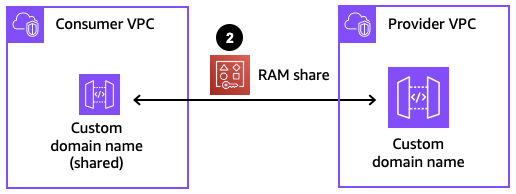
B. Routing to the correct gateway: APIM uses the URI prefix in the API mappings associated with custom domain names to route requests to the appropriate API gateway, as shown in the following figure. Each mapping defines a specific API, stage, and an optional path. When a request arrives, APIM checks the path and directs the request to the correct stage and API if it matches. Unmatched requests default to the mapping with no path defined.
C. APIM core processing: A Lambda function (APIM CORE) uses DynamoDB configurations to handle authentication, authorization, protocol conversion, field transformation, and routing.
D. Downstream service call: APIM forwards each request to the configured internal or external endpoint.
E. Logging and monitoring: API Gateway access logs and custom logs track requests in detail.
F. Alarm: Metrics and alarms detect anomalies and notify stakeholders. Use Amazon CloudWatch or self-hosted solutions such as ELK to enable real-time monitoring and alerting.
Conclusion
In this post, we’ve demonstrated how to build an enterprise API management (APIM) solution using Amazon API Gateway, AWS Lambda, Amazon DynamoDB, and other AWS services. We’ve also shown how APIM centralizes critical features—such as version management, security policies, and request/response transformations—to accommodate large-scale enterprise requirements.
You can use the APIM portal to store and manage configurations in DynamoDB, dynamically applying these settings to multiple API gateways without rewriting code. This approach ensures consistent governance across diverse client types and business scenarios, helping to keep APIs both secure and flexible.
Finally, you’ve seen how the APIM architecture unifies the management state and runtime state, streamlines administrative tasks, and provides end-to-end monitoring and alerting. By adopting these best practices, your enterprise can establish a robust, scalable, and secure API management foundation, all within a serverless paradigm.
Welcome to the 27th edition of the AWS Serverless ICYMI (in case you missed it) quarterly recap. At the end of a quarter, we share the most recent product launches, feature enhancements, blog posts, webinars, live streams, and other interesting things that you might have missed!
In case you missed our last ICYMI, check out what happened in Q2 here.
2024 Q4 calender
Serverless at re:Invent 2024
AWS re:Invent 2024 had 60,000 in-person attendees and 400,000 online viewers for the keynotes. The conference delivered 1,900 sessions from 3,500 speakers and included 546 AWS service and feature announcements.
The serverless content consisted of two tracks: Serverless (SVS) and App Integration (API). These tracks included 70 unique sessions and attracted nearly 11,000 attendees. Serverlesspresso, the coffee shop powered by serverless technology, operated in two locations during the event: the Expo Hall and the certification lounge.
AWS Lambda and Amazon Elastic Container Service (Amazon ECS) 10-year anniversary.
AWS marked significant milestones in serverless computing, celebrating 10 years of AWS Lambda and Amazon ECS. Lambda now serves over 1.5 million monthly customers and processes tens of trillions of requests each month. Amazon ECS launches more than 2.4 billion container tasks weekly and is used by over 65% of new AWS container customers.
AWS is commemorating this anniversary with insights from AWS Serverless Heroes, product leads, principal engineers, and AWS leadership sharing their perspectives on serverless evolution and future directions. These stories and insights are available at https://aws.amazon.com/serverless/10th-anniversary/.
AWS Lambda
The AWS Lambda team has spent a significant amount of time improving the Lambda development experience. Several enhancements have been made in the console as well as the local development experience.
Code-OSS as the new AWS Lambda inline editor
Lambda has launched a significant upgrade to its console by integrating Code-OSS, the open-source version of Visual Studio Code, delivering a familiar development experience directly in the cloud. The new Lambda Code Editor supports viewing larger function packages up to 50 MB, features a split-screen interface for simultaneous code editing and testing, and includes built-in Amazon Q Developer AI assistance for real-time coding suggestions. This enhancement comes at no additional cost and prioritizes accessibility with features like screen reader support and keyboard navigation. The update bridges the gap between cloud and local development by simplifying the process of downloading function code and AWS SAM templates, ultimately providing developers with a more streamlined and familiar serverless development experience. Watch the video explaining the changes in detail.
Lambda has expanded its runtime support by adding Python 3.13 and Node.js 22 as both managed runtimes and container base images, providing access to the latest language features and ensuring long-term support through October 2029 and April 2027, respectively.
Lambda introduces Provisioned Mode for Kafka event source mappings, allowing customers to optimize throughput by configuring dedicated event polling resources for applications with stringent performance requirements.
Finally, Lambda introduces an enhanced local development experience through the AWS Toolkit for Visual Studio Code, streamlining the serverless application development workflow. The update features a new Application Builder interface that guides developers through environment setup, offers sample applications, and provides quick-action buttons for common tasks like build, deploy, and invoke operations. Developers can now efficiently iterate on their code with features such as configurable build settings, step-through debugging, and the ability to sync local changes quickly to the cloud or perform full deployments. The toolkit integrates with AWS Infrastructure Composer for visual application building and includes comprehensive local testing capabilities with shareable test events. This enhancement simplifies the Lambda development process by enabling developers to author, test, debug, and deploy serverless applications without leaving their preferred IDE environment.
Local IDE getting started
Amazon ECS and AWS Fargate
AWS enhances observability for containerized applications with CloudWatch Application Signals for Amazon ECS, adding infrastructure metrics correlation to existing traces and logs monitoring, enabling operators to identify and resolve performance issues across their application stack.
Amazon ECS adds service revision and deployment history tracking, allowing customers to monitor changes, track ongoing deployments, and debug deployment failures for long-running applications deployed after October 25, 2024.
Service revisions and deployment history
Amazon ECS expands testing capabilities by supporting network fault injection experiments on AWS Fargate through AWS Fault Injection Service, enabling developers to verify application resilience using six different types of fault injection actions, including network disruptions and resource stress testing.
Amazon EventBridge
Amazon EventBridge announces significant performance improvements, reducing end-to-end latency by up to 94% from 2,235ms to 129.33ms at P99, enabling faster event processing for time-sensitive applications like fraud detection and gaming.
Step Functions also adds Variables and JSONata support to enhance workflow development. Variables allow data assignment and reference between states, simplifying payload management, while JSONata provides advanced data transformation capabilities, including date formatting and mathematical operations. These features reduce the need for custom code and intermediate states, making it easier to build distributed serverless applications. Watch the in depth video to learn more.
Amazon MQ adds support for AWS PrivateLink, enabling customers to access Amazon MQ API endpoints directly from their VPC through interface VPC endpoints, eliminating the need for internet access and providing enhanced security through AWS’s internal network infrastructure.
Amazon Finch
AWS announces general availability of Linux support for Finch, an open source container development tool that simplifies building, running, and publishing Linux containers across all major operating systems. The release includes support for the Finch Daemon with Docker API compatibility and is available through RPM packages for Amazon Linux 2 and Amazon Linux 2023.
Amazon Simple Queue Service (SQS)
Amazon SQS increases the in-flight message limit for FIFO queues from 20,000 to 120,000 messages, enabling higher concurrent message processing. This enhancement allows customers to scale their receivers and process up to six times more messages simultaneously, provided they have sufficient publish throughput.
Amazon Managed Streaming for Apache Kafka(Amazon MSK)
Amazon MSK now introduces Managed Streaming for Apache Flink blueprints to simplify real-time AI application development. The service enables vector-embedding generation through Amazon Bedrock, streamlining the integration of streaming data with generative AI models. Using a straightforward configuration process, users can generate and index vector embeddings in Amazon OpenSearch, while leveraging LangChain’s data chunking capabilities for enhanced data retrieval efficiency. The service handles all integration aspects between MSK, embedding models, and Amazon OpenSearch vector stores.
AWS Amplify
AWS Amplify launches the Amplify AI kit for Amazon Bedrock, providing fullstack developers with tools to integrate AI capabilities into web applications. The kit includes a customizable React UI component, secure Bedrock access, and context-sharing features, enabling developers to implement chat, search, and summarization functionalities without machine learning expertise.
AWS AppSync
AWS AppSync launches AppSync Events, enabling developers to broadcast real-time data to multiple subscribers through serverless WebSocket APIs. The service eliminates the need to build and manage WebSocket infrastructure while providing secure, scalable event broadcasting capabilities. Developers can create APIs that automatically scale and integrate with services like Amazon EventBridge. The system supports features such as channel namespaces, event handlers, and multiple authorization modes, and is available in all regions where AWS AppSync operates. Users only pay for API operations and real-time connection minutes used.
Creating an AppSunc Event API
Amazon API Gateway
Amazon API Gateway released a significant enhancement to Amazon API Gateway, enabling customers to manage private REST APIs using custom private DNS names. This highly requested feature allows API providers to use user-friendly domain names like private.example.com, while maintaining TLS encryption for security. The implementation process involves creating a private custom domain, configuring certificates through AWS Certificate Manager (ACM), mapping private APIs, and setting resource policies. The feature supports cross-account sharing through AWS Resource Access Manager (AWS RAM) and is now available in all AWS Regions, including AWS GovCloud (US).
The Serverless landing page has more information. The Lambda resources page contains case studies, webinars, whitepapers, customer stories, reference architectures, and even more Getting Started tutorials.
You can also follow the Serverless Developer Advocacy team on X (formerly Twitter) to see the latest news, follow conversations, and interact with the team.
Amazon Cognito is a developer-centric and security-focused customer identity and access management (CIAM) service that simplifies the process of adding user sign-up, sign-in, and access control to your mobile and web applications. Cognito is a highly available service that supports a range of use cases, from managing user authentication and authorization to enabling secure access to your APIs and workloads. It’s a managed service that can act as an identity provider (IdP) for your applications, can scale to millions of users, provides advanced security features, and can support identity federation with third-party IdPs.
A feature of Amazon Cognito is support for OAuth 2.0 client credentials grants, used for machine-to-machine (M2M) authorization. As your M2M use cases scale, it becomes important to have proper monitoring, optimization of token issuance, and awareness of security best practices and considerations. It’s a best practice for app clients to locally cache and reuse access tokens while still valid and not expired. You can customize how long issued tokens are valid, so it’s important to make sure that the timeframe is aligned with your security requirements. If caching and reusing access tokens isn’t possible at the client level or cannot be enforced, then combining your M2M use cases with a REST API proxy integration using Amazon API Gateway enables you to cache token responses. By using API Gateway caching, you can optimize the request and response of access tokens for M2M authorization. This reduces redundant calls to Cognito for access tokens, thus improving the overall performance, availability, and security of your M2M use cases.
In this post, we explore strategies to help monitor, optimize, and secure Amazon Cognito M2M authorization. You’ll first learn some effective monitoring techniques to keep track of your usage, then delve into optimization strategies using API Gateway and token caching. Lastly, we will cover security best practices and considerations to bolster the security of your M2M use cases. Let’s dive in and discover how to make the most out of your Amazon Cognito M2M implementation.
Machine-to-machine authorization
Amazon Cognito uses an OAuth 2.0 client credentials grant to handle M2M authorization. A Cognito user pool can issue a client ID and client secret to allow your service to request a JSON web token (JWT)-compliant access token to access protected resources. Figure 1 illustrates how an app client requests an access token using the client credentials grant flow with Amazon Cognito.
Figure 1: Client credentials grant flow
The client credential grant flow (Figure 1) includes the following steps:
The app client makes an HTTP POST request to the Amazon Cognito user pool /token endpoint (see The token issuer endpoint for more information), which provides an authorization header consisting of the client ID and client secret, and request parameters consisting of grant type, client ID, and scopes.
After validating the request, Cognito will return a JWT-compliant access token.
The client can make subsequent requests to a downstream resource server using the Cognito issued access token.
The resource server gets a JSON Web Key Set (JWKS) from the Cognito user pool. The JWKS contains the user pool’s public keys, which should be used to verify the token signature.
The resource server uses the public key to verify the signature of the access token is valid (proving the token has not been tampered with). The resource server also needs to verify that the token is not expired and required claims and values are present, including scopes. The resource server should use the aws-jwt-verify library to verify that the access token is valid.
After the access token is verified and the app client is authorized, the requested resource is returned to the app client.
Now, let’s dive deep into the monitoring, optimization, and security considerations around M2M authorization with Amazon Cognito.
Monitoring usage and costs
In May 2024, Amazon Cognito introduced pricing for M2M authorization to support continued growth and expand M2M features. Customer accounts using M2M with Cognito prior to May 9, 2024, are exempt from M2M pricing until May 9, 2025 (for more information, see Amazon Cognito introduces tiered pricing for machine-to-machine (M2M) usage). To get better visibility into your existing Amazon Cognito usage types, you can use the Security tab of the Cost and Usage Dashboards Operations Solution (CUDOS) dashboard. This dashboard is part of the Cloud Intelligence Dashboard, an opensource framework that provides AWS customers actionable insights and optimization opportunities at an organization scale. As shown in Figure 2, the Security tab in the CUDOS dashboard provides visuals that show the cost and spend of Amazon Cognito per usage type and the projected cost for M2M app clients and token requests after the exemption period with daily granularity. This daily breakdown allows you to track how your cost optimization efforts are trending.
Figure 2: Example Amazon Cognito spend and projected cost with daily granularity
You can also see the monthly spend per account for each usage type, as shown in Figure 3.
Figure 3: Example Amazon Cognito spend and projected cost per AWS account
You can see the usage and spend per resource ID of user pools contributing to the cost, as shown in Figure 4. This resource-level granularity enables you to identify the top spending user pool and prioritize usage and cost management efforts accordingly. An interactive demo of this dashboard is available. For more information, see Cloud Intelligence Dashboards.
Figure 4: Example Amazon Cognito resource usage and cost by resource ID, account, and AWS Region
In addition to using the CUDOS dashboard to help understand Cognito M2M usage and costs, you can also request fine-grained usage details down to the app client level. This can include the number of access tokens successfully requested per app client and the last time the app client was used to issue tokens. To understand fine-grained app client usage, you need to make sure that token requests include the client_id request query parameter. This will result in an AWS CloudTrail log event that includes the client ID within the additionalEventData JSON object that is associated with the client credentials token request, as shown in Figure 5.
Figure 5: Sample CloudTrail event log including client_id
You can also use an Amazon CloudWatch log group to capture and store your CloudTrail logs for longer retention and analysis. Then using CloudWatch Logs Insights, you can use the following sample query to gather app client usage.
fields additionalEventData.userPoolId as user_pool_id, additionalEventData.requestParameters.client_id.0 as client_id, eventName, additionalEventData.responseParameters.status
| filter additionalEventData.requestParameters.grant_type.0="client_credentials" and eventName="Token_POST" and additionalEventData.responseParameters.status="200"
| stats count(*) as count, latest(eventTime) as last_used by user_pool_id, client_id
| sort count desc
Figure 6 is an example result from the preceding CloudWatch Logs Insights query. The result includes the user_pool_id, client_id, count, and last_used columns. The total number of successful token requests grouped per user pool and client ID will be displayed in the count column and the last time the app client successfully issued an access token will be displayed in the last_used column.
Figure 6: Example screenshot result set from CloudWatch Logs Insights query
Optimizing token requests
Now that you know how to better monitor your Amazon Cognito usage and costs, let’s dive deeper into how to optimize your token requests usage. For M2M, it’s recommended that clients use mechanisms to locally cache access tokens to use for authorization. This will reduce the need for the client to request a new access token until the previously issued token is no longer valid. However, the environment where the client runs could be hosted by an external third party or owned by a different team and as the resource owner, you won’t have control over whether the third party implements token caching at the client side. If this is a scenario that you have, you can use a HTTP proxy integration to cache the access token using API Gateway. Because the M2M use case follows the client credentials grant flow of the OAuth 2.0 specification, the /token endpoint of your user pool is what will be configured with the API Gateway proxy integration. This proxy integration is where caching in API Gateway can be used. With caching, you can reduce the number of token requests made to your user pool /token endpoint and improve the latency of the client receiving a cached token in the response. With caching, you can achieve additional benefits, such as cost optimization, improved performance efficiency, higher levels of availability, and custom domain flexibility.
Solution overview
Figure 7: Token caching solution
The solution (shown in the Figure 7) includes the following steps.
The client makes an HTTP POST request to an API Gateway REST API.
The API Gateway method request caches the scope URL query string parameter and the Authorization HTTP request header as caching keys. The integration request is configured as a proxy to the /oauth2/token endpoint of your Amazon Cognito user pool.
Cognito validates the request, making sure that the client ID and client secret are correct from the authorization header, a valid client ID has been provided as a query string parameter, and the client is authorized for the requested scopes.
If the request is valid, Cognito returns an access token to the gateway through the integration response. With caching enabled, the response from the HTTP integration (Cognito token endpoint) is cached for the specified time-to-live (TTL) period.
The method response of the gateway returns the access token to the client.
Subsequent token requests with a remaining cached TTL will be returned, using the authorization header and scope as the caching keys.
To set up token caching, follow the steps in Managing user pool token expiration and caching. After a valid token request is returned through the API Gateway proxy integration and cached, subsequent token requests to the proxy that match the caching keys (authorization header and scope parameter) will return that same access token. This token will be returned to the client until the TTL of the cached token has expired. It’s recommended to set the TTL of the cache to be a few minutes less than the TTL of the access token issued from Amazon Cognito. For example, if your security posture requires access tokens to be valid for 1 hour, then set your caching TTL to be a few minutes less than the 1-hour token validity. It’s also important to understand the ideal caching capacity for your use case. The caching capacity affects the CPU, memory, and network bandwidth of the cache instance within the gateway. As a result, the cache capacity can affect the performance of your cache. See Enable Amazon API Gateway caching for more information. For information about how to determine the ideal cache capacity for your use case, see How do I select the best Amazon API Gateway Cache capacity to avoid hitting a rate limit?. Let’s now explore some security best practices and considerations to raise the security bar of your M2M use cases.
Security best practices
Now that you know how to monitor Amazon Cognito M2M usage and costs and how to optimize access token requests, let’s review some security best practices and considerations. Using OAuth 2.0 client credentials grant for M2M authorization helps protect your APIs. One of the key factors for this is that the access token used by the client to connect to the resource server is a temporary and time-bound token. The client must obtain a new access token after its previous token has expired so you won’t have to issue long-lived credentials that are used directly between the client and the resource server. The client ID and client secret remain confidential on the client and are only used between the client and the Amazon Cognito user pool to request an access token.
Use AWS Secrets Manager
If the workload is running on AWS, use AWS Secrets Manager so you don’t have to worry about hard-coding credentials into workloads and applications. If the workload is running on premises or through another provider, then use a similar secrets’ vault or privileged access management solution to house the workload credentials. The workload should retrieve credentials for authentication only at runtime.
Use AWS WAF
It’s a security best practice to use AWS WAF to protect your Amazon Cognito user pool endpoints. This can help protect your user pools from unwanted HTTP web requests by forwarding selected non-confidential headers, request body, query parameters, and other request components to an AWS WAF web access control list (ACL) associated with your user pool. By using AWS WAF, you can also add managed rule groups to your user pool, such as the AWS managed rule group for Bot Control, to add protection against automated bots that can consume excess resources, cause downtime, or perform malicious activities. Learn more about how to associate an AWS WAF Web ACL with your Cognito user pool.
Always verify tokens
After a client has obtained an access token, it’s important to make sure the client is authorized to access the requested resources. If the resource is using API Gateway and the built-in Amazon Cognito authorizer, then the integrity of the token, the signature, and token expiration are checked and validated for you. However, if you require a more custom authorization decision with API Gateway, you can use an AWS Lambda authorizer along with the aws-jwt-verify library. By doing so, you can verify that the signature of the JWT token is valid, make sure that the token isn’t expired, and that the necessary and expected claims are present (including necessary scopes). For more fine-grained authorization decisions, look into using Amazon Verified Permissions with the resource server or even within a Lambda authorizer. If the resource server is an external system that is, outside of AWS or a custom resource server, you want to make sure that the access token is validated and verified before the requested resources are returned to the client.
Define scopes at the app client level
It’s important to carefully define and constrain the scope of access for each app client to align with the principle of least privilege. By restricting each client ID to only the necessary scopes, organizations can minimize the risk of issuing access tokens with more access and permissions than is required. If your use case aligns with M2M multi-tenancy, consider creating a dedicated app client per tenant and using defined custom scopes for that tenant. Remember that the number of M2M app clients is a pricing dimension and will incur a cost. See Custom scope multi-tenancy best practices for more information.
Security considerations
If you’re using API Gateway to proxy token requests and caching access tokens, the following are some security considerations to raise the security bar of your M2M workload.
Allow token requests only through an API Gateway proxy
After your API Gateway proxy integration is configured and set up for optimization and you have AWS WAF configured for your user pool, you can add an additional layer of security by using an allow list so that only requests from your API Gateway proxy to your Amazon Cognito user pool are accepted. For this, inject a custom HTTP header within the integration request of the POST method execution and create an allow rule within your web ACL that looks for that specific header. You will also create an additional web ACL rule to block all traffic. The single allow rule will have a priority order of 0 and the block-all-traffic rule will have a priority order of 1. Ultimately, this will block all requests that go directly to your Cognito user pool /token endpoint and only allow requests that have been made through the API Gateway proxy. Figure 8 that follows is a deeper explanation of this setup.
Figure 8: Token caching solution with AWS WAF
The process shown in Figure 8 has the following steps:
The client makes a direct HTTP POST call to the /oauth2/token endpoint of the Amazon Cognito user pool. This request would be denied by the AWS WAF web ACL deny all rule.
The client initiates an OAuth2 client credentials grant (HTTP POST) against an API Gateway stage (/token).
The REST API gateway is a proxy integration to the /oauth2/token endpoint of the Cognito user pool.
Within the integration request settings, configure a custom header (for example, x-wafAuthAllowRule). Treat the value of this header as a secret that remains only within the API Gateway integration request and is not exposed outside of the gateway.
Consider using Lambda, Amazon EventBridge, and AWS Secrets Manager to automatically rotate this header value in both the API Gateway integration request and in the AWS WAF web ACL rule.
The request is proxied to the Cognito /oauth2/token endpoint and AWS WAF is configured to protect the Cognito user pool endpoints and therefore web ACL rules are evaluated.
The custom header from the integration request (the preceding step) is evaluated against the web ACL rules to allow this request.
Cognito will verify the authorization header (containing the client ID and client secret) and requested scopes.
After successful credential validation, an access token is returned to the gateway within the integration response.
The access token is cached using the following caching keys:
Authorization header.
Scope query string parameter.
The access token is returned to the client through API Gateway.
Subsequent token requests with a remaining cached TTL are returned to client immediately, using the authorization header and scope as the caching keys.
Additional authorizer with API Gateway
Using the client credentials grant is designed to obtain an access token so that an app client can access downstream resources. If you’re using API Gateway as a proxy integration to your token endpoint, as described previously, you can also use a separate authorizer with an API Gateway proxy. Therefore, to begin the OAuth 2.0 client credentials grant flow, a separate authorization takes place first. For example, if you’re in a highly regulated industry, you might require the use of mTLS authentication to obtain an access token. This might seem like a double-authentication scenario; however, this helps prevent unauthenticated attempts against your API Gateway proxy integration to get an access token from Amazon Cognito.
Encrypting the API cache
While configuring your API Gateway proxy integration and provisioning your API cache, you can enable encryption of the cached response data. Because this caches access tokens for the set TTL of your choosing, you should consider encrypting this data at rest if necessary to help meet your security requirements. You can use the default method caching or set an override stage-level caching and enable encryption at rest.
Conclusion
In this post, we shared how you can monitor, optimize, and enhance the security posture of your machine-to-machine (M2M) authorization use cases with Amazon Cognito. This involved using the Cost and Usage Dashboards Operations Solution (CUDOS) to understand your Cognito M2M token requests and costs. We also discussed using caching from Amazon API Gateway as an HTTP proxy integration to the Cognito user pool /oauth2/token endpoint. By following the guidance in this post, you can better understand your M2M usage and costs and achieve added benefits such as cost optimization, performance efficiency, and higher levels of availability. Lastly, we provided several security best practices and considerations that can be used as additional layers to elevate your security posture.
If you have feedback about this post, submit comments in the Comments section below. If you have questions about this post, start a new thread on Amazon Cognito re:Post or contact AWS Support.
This post is written by Kurt Tometich, Senior Solutions Architect, and Giedrius Praspaliauskas, Senior Solutions Architect, Serverless
Event-driven architectures face challenges with event validation due to unique domains, varying event formats, frequencies, and governance levels. Events are constantly evolving, requiring a balanced approach between speed and governance. This blog post describes approaches to consumer and producer event validation, focusing on automated solutions for producer validation using Amazon EventBridge and Amazon API Gateway.
Consumer and Producer Event Validation
In an event-driven system, events should be validated by both producers and consumers to maintain data integrity. The producers’ job is to create and send valid events before they are routed to consumers. Failing to do so can lead to data inconsistencies, downstream errors in processing and unnecessary costs. As a consumer, even if events come from a trusted source, validation should still be applied. Producers may change data format over time, data may become corrupt, or interfaces between the producer and consumer may alter it.
A common way to manage and route events is through an event bus. EventBridge is a serverless event bus that can perform discovery, versioning and consumption of event schemas. When schema discovery is enabled on an event bus, new schema versions are generated when the event structure changes. These schemas can be used to perform validation on events.
The EventBridge Schema registry stores schemas in OpenAPI or JSONSchema formats. Schemas can be added to the registry automatically through schema discovery or by manually uploading your schema to the registry through the AWS console or programmatically. Schema discovery automates the process of finding schemas and adding them to your registry. Schemas for AWS events are automatically added to the registry.
Once a schema is added to the registry, you can generate a code binding for the schema. This allows you to represent the event as a strongly typed object in your code. Code bindings are available for Golang, Java, Python, or TypeScript programming languages. If preferred language-specific bindings are not available, schemas can be downloaded and validated using third-party schema validation libraries. For example, Ajv for JavaScript or the jsonschema library for Python.
If using code bindings, you can download them using the console, API, or within a supported IDE using the AWS Toolkit. Code bindings can be used like other code artifacts. If an AWS Lambda function is used as a consumer, add the code binding as a layer dependency. Bindings are not automatically synced to any artifact repositories, such as AWS CodeArtifact. The Lambda function code in this solution can be extended to automate binding uploads to your artifact repository.
The following diagram depicts a common producer (left) and consumer (right) event architecture on AWS. Producers send events through API Gateway or directly to an EventBridge event bus. It’s common to use API Gateway as a front door to provide authorization, validation and pre-processing of incoming events. Events going directly to EventBridge may also come from SaaS Partner Integrations (Salesforce, Jira, ServiceNow, etc.) or an application running in a private subnet using the AWS private network to connect to EventBridge. For these events, you can use third-party libraries to validate events prior to them arriving on EventBridge.
Common Architecture for Producer and Consumer Event Validation
Workflow steps:
Producers send events through API Gateway or directly to EventBridge. API Gateway provides request validation, parses and sends events to EventBridge if they pass validation. Invalid events that do not match the schema in API Gateway will be rejected before reaching EventBridge. Events going directly to EventBridge are validated using third party schema validation libraries (e.g. Ajv for JavaScript and jsonschema library for Python).
With schema discovery enabled on a custom event bus, that bus will receive the event from an application and generate a new schema version in the registry. New schema versions are only created when the event structure changes. When new schema versions are created, a schema version created event is automatically emitted on the default EventBridge event bus. The default bus automatically receives AWS events. EventBridge rules can be configured to match all schema version changes or by filtering on schema name, type and other fields available on the event.
Consumers define EventBridge rules to react to schema version change events. Consumers download the schema or code bindings from EventBridge and perform validation and parsing.
Producers define EventBridge rules to react to schema version change events. The new schema is retrieved from the registry and either used in local development with third-party schema validation libraries, or a model in API Gateway is updated with the new schema directly. This step doesn’t exist as a native feature of EventBridge. The solution later in this post will demonstrate how to automate this step.
To scale this architecture to multiple event sources and API endpoints, you can create different models in API Gateway for each event schema. A model in API Gateway is a data schema that defines the structure and format of data for request and response payloads. Those models are then applied to different resources and methods defined on your APIs. The solutions below will demonstrate how event schemas can be automatically synced to models in API Gateway.
Solution Walkthrough
The following solutions use API Gateway to perform request validation and EventBridge schema discovery to automatically generate up-to-date schema versions. Both can be extended or modified to fit unique use cases. These solutions build upon the general producer and consumer validation architecture covered previously by incorporating automated solutions to downloading, processing and applying new schemas to API Gateway. Refer to the README.md file in the AWS Samples GitHub repository for pre-requisites, deployment instructions and testing.
Lambda Driven Schema Updater
The following architecture uses EventBridge schema discovery to generate new schema versions, download, process and post the schema to an API Gateway model for request validation. The Lambda schema updater function will trigger on schema version changes. The function trigger can be enabled or disabled by updating the rule in EventBridge console.
This solution is a good fit for quick updates with minimal processing. If complex testing and validation is required before updating a new schema, see the CI/CD driven schema updater solution covered later in this post. The rule in this solution triggers when a new schema version is added to the registry. To filter further, the rule can be modified or additional processing can be applied to the Lambda function. This provides flexibility in handling multiple domains or event types.
Architecture for Lambda Driven Schema Updater
Workflow Steps:
Producers send events to API Gateway endpoint or directly to EventBridge.
API Gateway performs request validation on the body, modifies the event format and sends to EventBridge. If the event does not match the schema, API Gateway will reject the request.
A custom event bus will receive the event and an optional rule based on source can log all events for tracking and troubleshooting.
With schema discovery enabled on custom event bus, new event structures generate schema versions that are stored in the registry. If a new schema version is generated, consumers can download latest schema and code bindings from the registry.
The schema version creation rule will invoke the Lambda function.
The function will download, process and update the API Gateway model with the new schema. A new schema version is only generated if the structure of the event changes.
CI/CD Driven Schema Updater
The alternative approach uses a CI/CD pipeline to control schema changes. Instead of the Lambda function directly applying the new schema to the API Gateway model, it downloads, processes, and stores the schema in a repository. The CI/CD pipeline references the stored schema, performing additional tests and checks before the schema is promoted and enforced. This provides more control over the schema update process, though it introduces some additional complexity. The following diagram describes the CI/CD driven update process. The solution can be adapted to other artifact repositories and CI/CD systems.
Architecture for CI/CD Driven Schema Updater
Workflow steps:
Producers send events to API Gateway endpoint or directly to EventBridge.
API Gateway will perform request validation against the body, modify the event format and send to EventBridge.
A custom event bus will receive event and an optional rule based on source can log all events for tracking and troubleshooting.
With discovery enabled on the custom event bus, schema versions are produced and stored in the registry.
The schema version creation rule will invoke the Lambda function.
The function will download, process and store the new schema in a repository of choice (i.e. S3, Git, Artifact Repository).
The CI/CD pipeline updates the model in API Gateway and runs any necessary tests.
The consumer downloads schema and code bindings from appropriate repositories.
Conclusion
Event validation can be challenging, but leveraging schema discovery and request validation minimizes custom logic and overhead. EventBridge can discover new schemas from events, while API Gateway validates incoming requests. This approach streamlines validation, improves data quality, and reduces the maintenance burden of manual validation.
For more information on event driven architectures, you can view additional resources on AWS Samples and Serverless Land.
This post is written by Heeki Park, Principal Solutions Architect
Amazon API Gateway is introducing custom domain name support for private REST API endpoints. Customers choose private REST API endpoints when they want endpoints that are only callable from within their Amazon VPC. Custom domain names are simpler and more intuitive URLs that you can use with your applications and were previously only supported with public REST API endpoints. Now you can use custom domain names to map to private REST APIs and share those custom domain names across accounts using AWS Resource Access Manager (AWS RAM).
Overview of API Gateway connectivity
When considering network connectivity with API Gateway, two aspects are important to keep in mind: the integration type and the connectivity type. The following diagram shows examples of those considerations.
Figure 1: Overall architecture
The first aspect is the distinction between frontend integrations and backend integrations. Frontend integrations are how API clients like mobile devices, web browsers, or client applications connect to the API endpoint. Backend integrations are the API services to which your API Gateway endpoint proxies requests, like applications running on Amazon Elastic Compute Cloud (EC2) instances, Amazon Elastic Kubernetes Service (EKS) or Amazon Elastic Container Service (ECS) containers, or as AWS Lambda functions. The second aspect is whether that connectivity is via the public internet or via your private VPC.
Calling private REST API endpoints
In order to send requests to a private REST API endpoint, clients must operate within a VPC that is configured with a VPC endpoint. Once a VPC endpoint is configured, a client has three different options within the VPC for connecting to the API endpoint, depending on how the VPC and the VPC endpoint are configured.
If the VPC endpoint has private DNS enabled, the client can send requests to the standard endpoint URL: https://{api-id}.execute-api.{region}.amazonaws.com/{stage}. These requests resolve to the VPC endpoint, which then get routed to the appropriate API Gateway endpoint.
Figure 2: VPC endpoint configured with private DNS names enabled
Alternatively, if the VPC endpoint has private DNS disabled, the client can send requests to the VPC endpoint URL: https://{vpce-id}.execute-api.{region}.amazonaws.com/{stage}. One of the following headers also needs to be sent along with that request.
Finally, if the VPC endpoint has private DNS disabled and the private REST API endpoint is associated with the VPC endpoint, the client can send requests to the following URL: https://{api-id}-{vpce-id}.execute-api.{region}.amazonaws.com/{stage}. To associate a VPC endpoint with a private API, the following property configures that association.
You can see that configuration in the console, as follows.
Figure 3: Optional VPC endpoint configuration with private REST API endpoints
To simplify access to your private REST API endpoints, you can now also configure custom domain names, which functions as a stable vanity URL for your private APIs.
Implementing custom domain names for private endpoints
Before setting up a custom domain name for your private REST API endpoints, a VPC endpoint for API Gateway, an AWS Certificate Manager (ACM) certificate, an Amazon Route 53 private hosted zone, and one or more private REST API endpoints need to be configured.
Once those pre-requisites are set up, a custom domain name can be setup with the following steps:
In the API provider account, create a custom domain name and base path mapping.
In the provider account, use AWS RAM to create a resource share for the custom domain name. In the consumer account, accept the resource share request. This step is only required if the provider and consumer are in different AWS accounts.
In the consumer account, associate the custom domain name to a VPC endpoint.
In the consumer account, create a Route 53 alias to map the custom domain to the VPC endpoint.
Figure 4: Components for configuring a custom domain name
Step 1: Creating a private custom domain name
When configuring a custom domain name, two policies are used to manage permissions to the private custom domain name resource. Management policies specify which principals are allowed to associate a private custom domain name to a VPC endpoint. Resource-based policies specify which API consumers are allowed to invoke your private custom domain name.
Figure 5: Creating a private custom domain name
This is an example CloudFormation definition for a private custom domain name.
In this example, the management policy specifies that the account 123456789012 is allowed to associate a private custom domain name with a VPC endpoint. The resource-based policy then denies any request that does not come from a particular VPC endpoint and only allows invoke requests that come from that same account 123456789012.
The private custom domain name then needs to be mapped to a private REST API.
In this example, the BasePath is set to app1. If the Stage is set as dev, then the private endpoint can be accessed via https://api.internal.example.com/app1/dev. The domain id is the identifier for the private custom domain name.
Note that with public custom domain names, the domain name has to be unique in the region, since they are resolved publicly. With private custom domain names, since they are resolved within a VPC, a private custom domain name with the same name can be created in different accounts. The private custom domain name is then resolved to the VPC endpoint in that account’s VPC.
Step 2: Sharing the private custom domain name using AWS RAM
In order for API consumers to access the private custom domain name from another account, the custom domain name needs to be shared with the consumer accounts using RAM. If the API provider and API consumer are in the same account, this step with RAM can be skipped.
Figure 6: Sharing the private custom domain name
The following CloudFormation definition creates a resource share in the provider account.
The allowed Principals for the resource share specifies the consumer account ids. The ResourceArns specify the ARN of the private custom domain name.
In the consumer account, an administrator receives a notification to accept the resource share. This request must be accepted to allow the consumer account to see the private custom domain name. This handshake acts as a mutual agreement between the accounts to allow the private custom domain name to be exposed from the provider account to the consumer account. If the provider and consumer accounts are in the same AWS Organization, the share is automatically accepted on behalf of consumers.
Step 3: Associating the private custom domain name to a VPC endpoint
The private custom domain name is now visible in the consumer account. Next, associate the private custom domain name with a VPC endpoint in the consumer account and in the VPC where the client applications reside.
Figure 7: Associating the private custom domain name to a VPC endpoint
The AccessAssociationSource is the VPC endpoint id, and the DomainNameArn is the same ARN that is used in the RAM resource share.
Step 4: Creating a Route 53 alias for the custom domain name
The final step before being able to test the custom domain name in the consumer account is setting up a Route 53 alias. That alias is configured in a private hosted zone that is associated with the VPC where the VPC endpoint and client applications reside. The alias resolves the fully qualified domain name (FQDN) to the VPC endpoint DNS name.
Figure 8: Creating a Route 53 alias
The following CloudFormation definition creates that alias.
The ResourceRecords point to the FQDN of the VPC endpoint to which our private custom domain name is associated. Once this alias is created, your client applications can test if it can successfully send requests to the private custom domain name.
Optional: Cleaning up the resources
If you’ve configured a test environment with these resources, you can clean up the deployment by following the steps in reverse order.
In the consumer account, delete the Route 53 alias.
In the consumer account, delete the association.
In both the consumer and provider account, remove the RAM resource share.
In the provider account, delete the custom domain name and base path mapping.
Conclusion
In this post, you learned about how clients can connect to private REST API endpoints with API Gateway. With custom domain names, your applications connect to stable URLs that can forward requests to many different private API backends. Furthermore, your application teams can deploy resources in separate line of business AWS accounts and access the private custom domain name as a central shared resource, using AWS RAM resource sharing. This allows your application teams to build secure, private API applications and expose them to API consumers securely and across multiple AWS accounts.
For more details, refer to the API Gateway documentation and check out patterns with API Gateway on Serverless Land.
Join AWS serverless experts and community members at the AWS Modern Apps and Open Source Zone in the AWS Expo Village. This serves as a hub for serverless discussions at re:Invent. While you are there, enjoy a free coffee and learn about serverless architectures at the Serverlesspresso booth. There are two this year, another one at the Certificate Lounge. The AWS Expo Village also includes Serverless and Serverless Containers booths.
Breakout Sessions are lecture-style presentations covering architecture, best practices, and deep dives into AWS services.
Workshops are 2-hour hands-on sessions where you work through tasks in AWS accounts using AWS services. Laptops are required and AWS credits are provided.
Chalk Talks are highly interactive 60-minute sessions with smaller audiences, focused on technical deep dives with whiteboards for architectural discussions.
Builders’ Sessions are 60-minute small-group sessions led by an AWS expert who guides you through a technical problem using AWS services.
Code Talks are 60-minute live coding sessions where AWS experts show how to build solutions using AWS services.
SVS211: Celebrating 10 years of pioneering serverless and containers – Breakout.
Explore how serverless has evolved to help organizations drive the highest performance, availability, and security at low costs.
Getting started sessions
Are you new to serverless or taking your first steps? Hear from AWS experts and customers on best practices and strategies for building serverless workloads. Get hands-on with services by attending a workshop or builders session. Create the next great “to do” app or add a new customer experience for a theme park.
SVS208: Balance consistency and developer freedom with platform engineering – Breakout
Learn how platform teams can provide opinionated security, cost, observability, reliability, and sustainability patterns while maintaining developer flexibility.
SVS209: Containers or serverless functions: A path for cloud-native success – Breakout
Explore the fundamental differences between containers and serverless functions through real-world scenarios and insights into choosing the right approach.
OPN301: Level up your serverless applications with Powertools for AWS Lambda – Workshop
Learn why Powertools for AWS Lambda can be the developer toolkit of choice for serverless workloads.
DEV341: From single to multi-tenant: Scaling a mission-critical serverless app
Explore how to transition a mission-critical application from a single-tenant to a multi-tenant architecture
Hear about a real-world project journey, from concept to production in only eight weeks. Expect practical insights, mistakes, tips, and how using the right technologies and development process can deliver results fast.
API204: Building event-driven architectures – Workshop
Learn about the basics of event-driven design using examples involving Amazon SNS, Amazon SQS, AWS Lambda, Amazon EventBridge, and more.
API206: How event-driven architectures can go wrong and how to fix them – Chalk Talk
Explore common event-driven pitfalls including YOLO events, god events, observability soup, event loops, and surprise bills.
DEV321: Choosing the right serverless compute services
Learn when to use AWS serverless compute services like AWS Lambda and Amazon ECS on AWS Fargate and how to integrate them into your application architectures.
API307: Event-driven architectures at scale: Manage millions of events – Breakout
Discover proven patterns for building high-scale event-driven systems that can be effectively managed across a distributed organization with Amazon EventBridge.
SVS206: Building an event sourcing system using AWS serverless technologies – Chalk Talk
Explore strategies for building effective event sourcing architectures using AWS serverless technologies to store application state as an append-only event log.
Join this code talk to learn best practices for collecting signals from your serverless applications. Dive deep into techniques to effectively instrument your applications to provide you with optimal observability.
API201: The AWS Step Functions workshop – Workshop
Learn about the features of AWS Step Functions through hands-on interactive modules.
API203: Building common orchestrated workflows with AWS Step Functions – Builders Session
Build three orchestrated workflows, including streamlined data processing with Distributed Map state, external system integration using callback, and implementing the saga pattern.
API207: Optimize data processing with built-in AWS Step Functions features – Chalk Talk
Learn to optimize your serverless data processing workflows at scale using AWS Step Functions features, including intrinsic functions and Distributed Map state.
API402: Building advanced workflows with AWS Step Functions – Breakout
Learn how you can use generative AI to generate state machines automatically from textual descriptions and chat with your workflow to optimize it.
API208: Building an integration strategy for the future – Breakout
Boost productivity and create better customer experiences by building a modern integration strategy using AWS application, data, and file integration services.
API306: Integration patterns for distributed systems – Breakout
Learn about common design trade-offs for distributed systems and how to navigate them with design patterns, illustrated with real-world examples.
API311: Application integration for platform builders – Breakout
Explore the implementation of application integration using serverless components in enterprise environments.
SVS203: Create your first API from scratch with OpenAPI and Amazon API Gateway – Builders Session
Learn how to design and provision complete APIs using infrastructure as code following the OpenAPI specification.
API303: Building modern API architectures: Which front door should I use? – Chalk Talk
Explore options for building modern APIs including REST, GraphQL, and real-time APIs along with their benefits and drawbacks.
API304: Building rate-limited solutions on AWS – Chalk Talk
Learn some of the best ways to build rate limiting into your systems for improved reliability.
API305: Asynchronous frontends: Building seamless event-driven experiences – Breakout
Explore patterns to enable asynchronous, event-driven integrations with the frontend designed for architects and frontend, backend, and full-stack engineers.
SVS401: Best practices for serverless developers – Breakout
Discover architectural best practices, optimizations, and useful shortcuts for building production-ready serverless workloads.
SVS403: From serverful to serverless Java – Workshop
Learn how to bring your traditional Java Spring application to AWS Lambda with minimal effort and iteratively apply optimizations.
SVS406: Scale streaming workloads with AWS Lambda – Chalk Talk
Learn how to implement parallel processing techniques for ordered and unordered use cases to address throughput limitations in streaming data processing.
Explore advanced strategies for managing multi-tenant Amazon SQS queues and effective mitigation techniques, including shuffle sharding and overflow queues.
SVS321: AWS Lambda and Apache Kafka for real-time data processing applications – Breakout
Gain practical insights into building scalable, serverless data processing applications by integrating AWS Lambda with Apache Kafka.
API209: Generative AI at scale: Serverless workflows for enterprise-ready apps – Workshop
Learn to build enterprise-ready, scalable generative AI applications that can scale from serving 100 to 100,000 users.
API310: Build a meeting summarization solution with generative AI & serverless – Code Talk
See live coding of a serverless application for producing meeting summaries with generative AI using Amazon Transcribe and Amazon Bedrock, orchestrated with AWS Step Functions.
SVS319: Unlock the power of generative AI with AWS Serverless – Breakout
Learn to harness AWS Serverless to build robust, cost-effective generative AI applications. Explore using AWS Step Functions to orchestrate complex AI workflows.
SVS325: Secure access to enterprise generative AI with serverless AI gateway – Chalk Talk
Explore how to architect a serverless AI gateway on AWS to securely integrate and consume large language models from multiple providers.
If you are attending re:Invent, connect at our AWS Modern Apps and Open Source Zone in the AWS Expo Village. The AWS Expo Village also includes Serverless and Serverless Containers booths.
If you can not join us in-person, breakout sessions will be available via our YouTube channel after the event.
We look forward to seeing you at re:Invent 2024! For more serverless learning resources, visit Serverless Land.
AWS Lambda is introducing a new code editing experience in the AWS console based on the popular Code-OSS, Visual Studio Code Open Source code editor. This brings the familiar Visual Studio Code interface and many of the features directly into the Lambda console, allowing developers to use their preferred coding environment and tools in the cloud. The Lambda Code Editor displays larger function package sizes and also integrates with Amazon Q Developer. This is an AI-powered coding assistant that provides real-time suggestions and insights to help you write, understand, and troubleshoot your Lambda functions more efficiently.
Overview
Visual Studio Code is the most popular IDE among developers according to the 2023 Stack Overflow Developer Survey. Integrating Code-OSS into the Lambda Console brings a familiar, accessible, and customizable interface to the in-browser code editing capabilities. This provides a coding experience that is substantially similar to working with function code locally. You can install selected extensions, apply preferred themes and settings, and use your familiar keyboard shortcuts and coding preferences.
The new editing experience is included as part of the standard Lambda service, at no extra cost.
Accessibility
The update also addresses important accessibility needs. With features like high color contrast, keyboard-only navigation, and screen reader support, the Code-OSS integration ensures an inclusive and accessible coding experience for all developers.
Differences from Visual Studio Code IDE
The Lambda console’s Code-OSS integration complements, rather than fully replaces, local development workflows. You can view and edit function code that uses an interpreted language, not compiled languages, which is consistent with the previous Lambda console. The terminal window is also unavailable in Code-OSS.
AWS Toolkit for Visual Studio Code extensions
Deeper integration with the AWS Toolkit for VS Code extension provides access to a subset of AWS specific functionality, including Q Developer. This ensures that the Lambda code editing experience benefits from additional developer tooling enhancements provided through the AWS Toolkit.
Larger package sizes
With Lambda, the total package size for ZIP-based functions, including code and libraries, cannot exceed 50 MB. Previously Lambda imposed a 3MB limit for editing code in the console. Now you are able to view function package sizes up to 50 MB in the console, however, there is still a single file limit of 3 MB. This allows you to view function code even when you have larger dependencies.
Using the new features
Viewing code
To experience the new Lambda Code Editor, log into the AWS Management Console and navigate to the Lambda service. Create a new function or edit an existing one. The new Lambda Code Editor is ready to use, with no additional setup required.
This example shows editing an existing function, viewing the function code in the familiar Code-OSS editor.
Viewing function code in the Lambda Code Editor
Previously, the code was not viewable as the code package size was greater than 3 MB. The update allows you to view larger files. The following image shows a package size of 13.3 MB and the Code-OSS editor allows editing of the function handler.
Viewing larger package size
Environment variables
In the left pane, the environment variables are viewable for the function. Select the pencil icon to edit, add, and remove environment variables.
Viewing and editing environment variables
Creating test events
The new split-screen view allows you to test your function and see your code and test results side-by-side, simplifying test event configuration.
Select Create test event to open the panel.
Creating test event
You can create Private test events or Shareable test events for other builders to use with access to the account.
Generate an event using an event template for the Amazon API Gateway HTTP API event trigger that the function uses. Save the test event.
Creating API Gateway test event
Invoke function
Invoke the function by selecting the Invoke button
The function results appear in the Output panel, consistent with the local VS Code IDE experience.
Function invoke result
The function logs appear below the output.
Viewing function logs
This view allows you to view and edit your code, generate and use test events, and invoke your function, all visible within the familiar Lambda Code Editor interface.
Live Tail Logs
Lambda now natively supports Amazon CloudWatchLogs Live Tail. This is an interactive log streaming and analytics capability, which allows you to view and analyze your Lambda function logs in real time.
Select the Run and Debug icon in the Activity Bar on the left-hand side of the code editor in the Code tab.
Select Open CloudWatch Live Tail. This opens the CloudWatch Logs Live Tail bottom drawer.
Select Start to start a Live Tail session and view your Lambda function logs stream in real time.
Alternatively, navigate to the Test tab and select CloudWatch Logs Live Tail to start a Live Tail session.
CloudWatch Logs Live Tail
Keyboard shortcuts
In the left pane Extensions dialog, you can see the keyboard shortcuts are installed by default.
Viewing installed extensions
Select the Manage gear icon which shows which aspects are configurable.
Viewing configuration options
The Keyboard shortcuts dialog allows you to view and change the shortcuts.
Amending keyboard shortcuts
Command Palette
Viewing the Command Palette shows available commands.
Viewing Command Palette
Configuration settings
The Settings panel allows you to configure the Lambda Code Editor to match your local IDE environment if required.
Viewing Settings panel
Navigate to Themes | Color Themes to customize the theme, including dark mode.
Lambda Console Editor dark mode
Downloading function code and template
It is now easier to download the function code and an AWS Serverless Application Model (AWS SAM) template which represents the Cloudformation resources required to set up the function, policies, and triggers. This allows you to start in the console and more easily move to using infrastructure as code, which is a serverless best practice.
Navigate to the Activity Bar Run and Debug section.
Select Download code and SAM template.
Extract the .zip file and open the folder in your local VS Code IDE.
You can continue to edit the function in your local IDE experience, which is consistent with the Lambda Console Editor.
Local VS Code IDE to continue working on function
Using your local IDE terminal or AWS Toolkit for VS Code, you can update the existing function. You can also use AWS SAM functionality to build and deploy the template as a Cloudformation stack to the cloud.
Using Amazon Q
The Amazon Q Developer AI assistant integrates directly into the code editor. This reduces the need to consult external documentation or tutorials, streamlining your development workflow.
Amazon Q provides inline suggestions or by using keyboard shortcuts for common actions you take, such as initiating Amazon Q or accepting a recommendation.
This example below adds more functionality to a new Lambda function to download an object from S3 with the help of Amazon Q. Enter a comment explaining the functionality you need.
Asking Amazon Q a question
Select tab to accept the suggestion.
Accepting an Amazon Q suggestion
You can continue to invoke Q manually to keep adding more code suggestions.
Continue adding functionality with Amazon Q
Conclusion
Lambda is introducing a new AWS console code editing experience based on the popular Code-OSS, Visual Studio Code Open Source code editor. This brings the familiar VS Code IDE interface and features directly into the Lambda console so you can use your preferred coding environment and tools in the cloud. Invoke your function using a new split-screen view to see your code and test results side-by-side, simplifying test event configuration.
The code editor displays larger function package sizes, makes environment variables more visible, and also integrates with Amazon Q Developer. This provides real-time suggestions and insights to help you write, understand, and troubleshoot your Lambda functions more efficiently.
For more serverless learning resources, visit Serverless Land.
In today’s fast-paced software as a service (SaaS) landscape, tenant portability is a critical capability for SaaS providers seeking to stay competitive. By enabling seamless movement between tiers, tenant portability allows businesses to adapt to changing needs. However, manual orchestration of portability requests can be a significant bottleneck, hindering scalability and requiring substantial resources. As tenant volumes and portability requests grow, this approach becomes increasingly unsustainable, making it essential to implement a more efficient solution.
This blog post delves into the significance of tenant portability and outlines the essential steps for its implementation, with a focus on seamless integration into the SaaS serverless reference architecture. The following diagram illustrates the tier change process, highlighting the roles of tenants and admins, as well as the impact on new and existing services in the architecture. The subsequent sections will provide a detailed walkthrough of the sequence of events shown in this diagram.
Figure 1. Incorporating tenant portability within a SaaS serverless reference architecture
Why do we need tenant portability?
Flexibility: Tier upgrades or downgrades initiated by the tenant help align with evolving customer demand, preferences, budget, and business strategies. These tier changes generally alter the service contract between the tenant and the SaaS provider.
Quality of service: Generally initiated by the SaaS admin in response to a security breach or when the tenant is reaching service limits, these incidents might require tenant migration to maintain service level agreements (SLAs).
High-level portability flow
Tenant portability is generally achieved through a well-orchestrated process that ensures seamless tier transitions. This process comprises of the following steps:
Figure 2. High-level tenant portability flow
Port identity stores: Evaluate the need for migrating the tenant’s identity store to the target tier. In scenarios where the existing identity store is incompatible with the target tier, you’ll need to provision a new destination identity store and administrative users.
Update tenant configuration: SaaS applications store tenant configuration details such as tenant identifier and tier that are required for operation.
Resource management: Initiate deployment pipelines to provision resources in the target tier and update infrastructure-tenant mapping tables.
Data migration: Migrate tenant data from the old tier to the newly provisioned target tier infrastructure.
Cutover: Redirect tenant traffic to the new infrastructure, enabling zero-downtime utilization of updated resources.
Consideration walkthrough
We’ll now delve into each step of the portability workflow, highlighting key considerations for a successful implementation.
1. Port identity stores
The key consideration for porting identity is migrating user identities while maintaining a consistent end-user experience, without requiring password resets or changes to user IDs.
Create a new identity store and associated application client that the frontend can use; after that, we’ll need a mechanism to migrate users. In the reference architecture using Amazon Cognito, a silo refers to each tenant having its own user pool, while a pool refers to multiple tenants sharing a user pool through user groups.
To ensure a smooth migration process, it’s important to communicate with users and provide them with options to avoid password resets. One approach is to notify users to log in before a deadline to avoid password resets. Employ just-in-time migration, enabling password retention during login for uninterrupted user experience with existing passwords.
However, this requires waiting for all users to migrate, potentially leading to a prolonged migration window. As a complementary measure, after the deadline, the remaining users can be migrated by using bulk import, which enforces password resets. This ensures a consistent migration within a defined timeframe, albeit inconveniencing some users.
2. Update tenant configuration
SaaS providers rely on metadata stores to maintain all tenant-related configuration. Updates to tenant metadata should be completed carefully during the porting process. When you update the tenant configuration for the new tier, two key aspects must be considered:
Retain tenant IDs throughout the porting process to ensure smooth integration of tenant logging, metrics, and cost allocation post-migration, providing a continuous record of events.
Establish new API keys and a throttling mechanism tailored to the new tier to accommodate higher usage limits for the tenants.
To handle this, a new tenant portability service can be introduced in the SaaS reference architecture. This service assigns a different AWS API Gateway usage plan to the tenant based on the requested tier change, and orchestrates calls to other downstream services. Subsequently, the existing tenant management service will need an extension to handle tenant metadata updates (tier, user-pool-id, app-client-id) based on the incoming porting request.
3. Resource management
Successful portability hinges on two crucial aspects during infrastructure provisioning:
Ensure tenant isolation constructs are respected in the porting process through mechanisms to prevent cross-tenant access. Either role-based access control (RBAC) or attribute-based-access control (ABAC) can be used to ensure this. ABAC isolation is generally easier to manage during porting if the tenant identifier is preserved, as in the previous step.
Ensure instrumentation and metric collection are set up correctly in the new tier. Recreate identical metric filters to ensure monitoring visibility for SaaS operations.
To handle infrastructure provisioning and deprovisioning in the reference architecture, extend the tenant provisioning service:
Update the tenant-stack mapping table to record migrated tenant stack details.
Initiate infrastructure provisioning or destruction pipelines as needed (for example, to run destruction pipelines after the data migration and user cutover steps).
Finally, ensure new resources comply with required compliance standards by applying relevant security configurations and deploying a compliant version of the application.
By addressing these aspects, SaaS providers can ensure a seamless transition while maintaining tenant isolation and operational continuity.
4. Data migration
The data migration strategy is heavily influenced by architectural decisions such as the storage engine and isolation approach. Minimizing user downtime during migration requires a focus on accelerating the migration process, maintaining service availability, and setting up a replication channel for incremental updates. Additionally, it’s crucial to address schema changes made by tenants in a silo model to ensure data integrity and avoid data loss when transitioning to a pool model.
Extending the reference architecture, a new data porting service can be introduced to enable Amazon DynamoDB data migration between different tiers. DynamoDB partition migration can be accomplished through multiple approaches, including AWS Glue, custom scripts, or duplicating DynamoDB tables and bulk-deleting partitions. We recommend a hybrid approach to achieve zero-downtime migration. This solution applies only when the DynamoDB schema remains consistent across tiers. If the schema has changed, a custom solution is required for data migration.
5. Cutover
The cutover phase involves redirecting users to the new infrastructure, disabling continuous data replication, and ensuring that compliance requirements are met. This includes running tests or obtaining audits/certifications, especially when moving to high-sensitivity silos. After a successful cutover, cleanup activities are necessary, including removing temporary infrastructure and deleting historical tenant data from the previous tier. However, before deleting data, ensure that audit trails are preserved and compliant with regulatory requirements, and that data deletion aligns with organizational policies.
Conclusion
In conclusion, portability is a vital feature for multi-tenant SaaS. It allows tenants to move data and configurations between tiers effortlessly and can be incorporated in reference architecture as above. Key considerations include maintaining consistent identities, staying compliant, reducing downtime and automating the process.
This post is written by Marcos Ortiz, Principal AWS Solutions Architect and Khubyar Behramsha, Sr. AWS Solutions Architect.
In this post, you learn how organizations can evolve from a single-Region architecture API Gateway to a multi-Region one, using a reliable failover mechanism without dependencies on AWS control plane operations. An AWS Well-Architected best practice is to rely on the data plane and not the control plane during recovery. Failover controls should work with no dependencies on the primary Region. This pattern shows how to independently failover discrete services deployed behind a shared public API. Additionally, there is a walkthrough on how to deploy and test the proposed architecture, using our open-source code available on GitHub.
For many organizations, running services behind a Regional Amazon API Gateway endpoint aligned to AWS Well-Architected best practices, offers the right balance of resilience, simplicity, and affordability. However, depending on business criticality, regulatory requirements, or disaster recovery objectives, some organizations must deploy their APIs using a multi-Region architecture.
When dealing with business-critical applications, organizations often want full control over how and when to trigger a failover. A manually triggered failover allows for dependencies to be failed over in a specific order. Failover actions follow the chain of approvals needed, which helps prevent failing over to an unprepared replica or other flapping issues caused by intermittent disruptions. While the failover action or trigger has a human-in-the-loop component, the recommendation is for all subsequent actions to be automated as much as possible. This approach gives application owners control over the failover process, including the ability to trigger the failover in cases of intermittent issues.
Overview
One common approach for customers is to deploy a public Regional API with a custom domain name, providing more intuitive URLs for their users. The backend uses API mappings to connect multiple API stages to a custom domain. This approach allows service owners to deploy their services independently while sharing the same top-level API domain name. Here is a typical architecture that follows this pattern:
Regional endpoint with mapping
However, when trying to evolve this to a multi-Region architecture, organizations often struggle to fail over each service independently. If the preceding architecture is deployed in two Regions as-is, it becomes an all-or-nothing scenario, where organizations must either fail over all the services behind API Gateway or none.
Evolving to a multi-Region architecture
To enable each team to manage and failover their services independently, you can implement this new approach for a multi-Region architecture. Each service has its own subdomain, using API Gateway HTTP integrations to route the request to a given service. This allows the service APIs the flexibility to be independently failed over, or all at once, with the shared public API.
Multi-Region architecture
This is the request flow:
Users access a specific service through the public shared API domain name using a URL suffix. For instance, to access service1, the end user would send a request to http://example.com/service1.
Amazon Route 53 has the top-level domain, example.com, registered with a primary and a secondary failover record. It routes the request to the API Gateway external API endpoint in the primary Region (us-east-1).
Amazon Route 53, has the domain service1.example.com registered with a primary and a secondary failover record. It routes the request to the API Gateway service1 API Regional endpoint in the primary Region (us-east-1) when healthy and routes to the service1 API Regional endpoint in the secondary Region (us-west-2) when unhealthy.
Represents the primary route for service1 configured in Amazon Route 53.
Represents the secondary route for service1 configured in Amazon Route 53.
This solution requires deploying each service API in both the primary (us-east-1) and secondary (us-west-2) Regions. Both Regions use the same custom domain configuration. For the primary Region, primary DNS records for each service point to the Regional API Gateway distribution endpoint. In the secondary Region, secondary DNS records for each service point to the Regional API Gateway distribution endpoint in the secondary Region.
Route 53 records
Active-passive manual failover
The example provided here enables a reliable failover mechanism that does not rely on the Amazon Route 53 control plane. It uses Amazon Route 53 Application Recovery Controller (Route 53 ARC), which provides a cluster with five Regional endpoints across five different AWS Regions. The failover process uses these endpoints, instead of manually editing Amazon Route 53 DNS records, which is a control plane operation. The routing controls in Route 53 ARC failover traffic from the primary Region to the secondary one.
Route 53 ARC routing controls
Routing controls are on-off switches that enable you to redirect client traffic from one instance of your workload to another. Traffic re-routing is the result of setting associated DNS health checks as healthy or unhealthy.
An AWS Certificate Manager certificate (*.example.com) for your domain name on both the primary and secondary Regions you plan to deploy the sample APIs.
Deploy the Amazon Route 53 ARC stack
Deploy the Amazon Route 53 ARC stack first, which creates a cluster and the routing controls that enable you to fail over the APIs.
Deploy the Service1 API both in the primary and secondary Regions
This deploys an API Gateway Regional endpoint in each Region, which calls an AWS Lambda function to return the service name and the current AWS Region serving the request:
Deploy the shared public API both in the primary and secondary Regions
This step configures HTTP endpoints so that when you call example.com/service1 or example.com/service2, it routes the request to the respective public DNS records you have set up for service1 and service2.
To test the deployed example, modify then run the provided test script:
Update lines 3–5 in the test.sh file to reference the domain name you configured for your APIs.
Provide execute permissions and run the script:
chmod +x ./test/sh
./test.sh
This script sends an HTTP request to each one of your three endpoints every 5 seconds. You can then use Amazon Route 53 ARC to fail over your services independently and see the responses served from different Regions.
Initially, all services are routing traffic to the us-east-1 Region:
Initial routing
With the following command, you update two routing controls for service1, setting the primary Region (us-east-1) health check state to off, and the secondary Region (us-west-2) health check state to on:
After a few seconds, the script terminal shows that service1 is now routing traffic to us-west-2, while the other services are still routing traffic to the us-east-1 Region.
Flipping service1 to backup Region
To fail back service1 to the us-east-1 Region, run this command, now setting the service1 primary Region (us-east-1) health check state to on, and the secondary Region (us-west-2) health check state to off:
This solution helps put the control back in the hands of the teams managing critical workloads using API Gateway. By decoupling the frontend and backend, this solution gives organizations granular control over failover at the service level using Amazon Route 53 ARC to remove dependencies on control plane actions.
The pattern outlined also reduces the impact to consumers of the service as it allows you to use the same public API and top-level domain when moving from a single-Region to a multi-Region architecture.
Welcome to the 26th edition of the AWS Serverless ICYMI (in case you missed it) quarterly recap. Every quarter, we share all the most recent product launches, feature enhancements, blog posts, webinars, live streams, and other interesting things that you might have missed!
In case you missed our last ICYMI, check out what happened last quarter here.
Calendar
EDA Day – London 2024
The AWS Serverless DA team hosted the third Event-Driven Architecture (EDA) Day in London on May 14th. This event brought together prominent figures in the event-driven architecture community, AWS, and customer speakers.
EDA Day covered 13 sessions, 2 workshops, and a Q&A panel. David Boyne was the keynote speaker with a talk “Complexity is the Gotcha of Event-Driven Architecture”. There were AWS speakers including Matthew Meckes, Natasha Wright, Julian Wood, Gillian Amstrong, Josh Kahn, Veda Ramen, and Uma Ramadoss. There was also an impressive lineup of guest speakers, Daniele Frasca, David Anderson, Ryan Cormack, Sarah Hamilton, Sheen Brisals, Marcin Sodkiewicz, and Ben Ellerby.
There has been a lot of talk about the future of serverless, with this year being the 10th anniversary of AWS Lambda. Eric Johnson addresses the topic in his ServerlessDays Milan keynote, “Now serverless is all grown up, what’s next”.
AWS Lambda
AWS launched support for the latest release of Ruby 3.3 is based on the new Amazon Linux 2023 runtime. The Ruby 3.3 runtime also provides access to the latest Ruby language features.
Learn how to run code after returning a response from an AWS Lambda function. This post shows how to return a synchronous function response as soon as possible, yet also perform additional asynchronous work after you send the response. For example, you may store data in a database or send information to a logging system.
See how you can use the circuit-breaker pattern with Lambda extensions and Amazon DynamoDB. The circuit breaker pattern can help prevent cascading failures and improve overall system stability.
Amazon Timestream for LiveAnalytics is now an EventBridge Pipes target. Timestream for LiveAnalytics is a fast, scalable, purpose-built time series database that makes it easy to store and analyze trillions of time series data points per day.
EventBridge has a new console dashboard which provides a centralized view of your resources, metrics, and quotas. The console has an improved Learn page and other console enhancements. When using the CloudFormation template export for Pipes, you can also generate the IAM role. There is a new Rules tab in the Event Bus detail page, and the monitoring tab in the Rule detail page now includes additional metrics.
The new Bedrock Converse API provides a consistent way to invoke Amazon Bedrock models and simplifies multi-turn conversations. There is also a JavaScript tutorial to walk you through sending requests to the Converse API using the Javascript SDK.
Amazon Q Developeris now generally available. Amazon Q Developer, part of the Amazon Q family, is a generative AI–powered assistant for software development. Amazon Q is available in the AWS Management Console and as an integrated development environment (IDE) extension for Visual Studio Code, Visual Studio, and JetBrains IDEs. Amazon Q Developer has knowledge of your AWS account resources and can help understand your costs.
Amazon API Gateway now allows you to increase the integration timeout beyond the prior limit of 29 seconds. You can raise the integration timeout for Regional and private REST APIs, but this might require a reduction in your account-level throttle quota limit. This launch can help with workloads that require longer timeouts, such as Generative AI use cases with Large Language Models (LLMs).
You can also now use Amazon Verified Permissions to secure API Gateway REST APIs when using an Open ID connect (OIDC) compliant identity provider. You can now control access based on user attributes and group memberships, without writing code.
AWS AppSync
You can now invoke your AWS AppSync data sources in an event-driven manner. Previously, you could only invoke Lambda functions synchronously from AWS AppSync. AWS AppSync can now trigger Lambda functions in Event mode, asynchronously decoupling the API response from the Lambda invocation, which helps with long-running operations.
AWS AppSync now passes application request headers to Lambda custom authorizer functions. You can make authorization decisions based on the value of the authorization header, and the value of other headers that were sent with the request from the application client.
AWS Amplify Gen 2 is now generally available. This now provides a code-first developer experience for building full-stack apps using TypeScript. Amplify Gen 2 allows you to express app requirements like the data models, business logic, and authorization rules in TypeScript.
The Serverless landing page has more information. The Lambda resources page contains case studies, webinars, whitepapers, customer stories, reference architectures, and even more Getting Started tutorials.
You can also follow the Serverless Developer Advocacy team on X (formerly Twitter) to see the latest news, follow conversations, and interact with the team.
GitHub Actions is a continuous integration and continuous deployment platform that enables the automation of build, test and deployment activities for your workload. GitHub Self-Hosted Runners provide a flexible and customizable option to run your GitHub Action pipelines. These runners allow you to run your builds on your own infrastructure, giving you control over the environment in which your code is built, tested, and deployed. This reduces your security risk and costs, and gives you the ability to use specific tools and technologies that may not be available in GitHub hosted runners. In this blog, I explore security, performance and cost best practices to take into consideration when deploying GitHub Self-Hosted Runners to your AWS environment.
Best Practices
Understand your security responsibilities
GitHub Self-hosted runners, by design, execute code defined within a GitHub repository, either through the workflow scripts or through the repository build process. You must understand that the security of your AWS runner execution environments are dependent upon the security of your GitHub implementation. Whilst a complete overview of GitHub security is outside the scope of this blog, I recommended that before you begin integrating your GitHub environment with your AWS environment, you review and understand at least the following GitHub security configurations.
Federate your GitHub users, and manage the lifecycle of identities through a directory.
Limit administrative privileges of GitHub repositories, and restrict who is able to administer permissions, write to repositories, modify repository configurations or install GitHub Apps.
Limit control over GitHub Actions runner registration and group settings
In almost all cases, you do not need long-lived AWS Identity and Access Management (IAM) credentials (access keys) even for services that do not “run” on AWS – you can extend IAM roles to workloads outside of AWS without requiring you to manage long-term credentials. With GitHub Actions, we suggest you use OpenID Connect (OIDC). OIDC is a decentralized authentication protocol that is natively supported by STS using sts:AssumeRoleWithWebIdentity, GitHub and many other providers. With OIDC, you can create least-privilege IAM roles tied to individual GitHub repositories and their respective actions. GitHub Actions exposes an OIDC provider to each action run that you can utilize for this purpose.
Short lived AWS credentials with GitHub self-hosted runners
If you have many repositories that you wish to grant an individual role to, you may run into a hard limit of the number of IAM roles in a single account. While I advocate solving this problem with a multi-account strategy, you can alternatively scale this approach by:
using attribute based access control (ABAC) to match claims in the GitHub token (such as repository name, branch, or team) to the AWS resource tags.
using role based access control (RBAC) by logically grouping the repositories in GitHub into Teams or applications to create fewer subset of roles.
use an identity broker pattern to vend credentials dynamically based on the identity provided to the GitHub workflow.
Use Ephemeral Runners
Configure your GitHub Action runners to run in “ephemeral” mode, which creates (and destroys) individual short-lived compute environments per job on demand. The short environment lifespan and per-build isolation reduces the risk of data leakage , even in multi-tenanted continuous integration environments, as each build job remains isolated from others on the underlying host.
As each job runs on a new environment created on demand, there is no need for a job to wait for an idle runner, simplifying auto-scaling. With the ability to scale runners on demand, you do not need to worry about turning build infrastructure off when it is not needed (for example out of office hours), giving you a cost-efficient setup. To optimize the setup further, consider allowing developers to tag workflows with instance type tags and launch specific instance types that are optimal for respective workflows.
There are a few considerations to take into account when using ephemeral runners:
A job will remain queued until the runner EC2 instance has launched and is ready. This can take up to 2 minutes to complete. To speed up this process, consider using an optimized AMI with all prerequisites installed.
Since each job is launched on a fresh runner, utilizing caching on the runner is not possible. For example, Docker images and libraries will always be pulled from source.
Use Runner Groups to isolate your runners based on security requirements
By using ephemeral runners in a single GitHub runner group, you are creating a pool of resources in the same AWS account that are used by all repositories sharing this runner group. Your organizational security requirements may dictate that your execution environments must be isolated further, such as by repository or by environment (such as dev, test, prod).
Runner groups allow you to define the runners that will execute your workflows on a repository-by-repository basis. Creating multiple runner groups not only allow you to provide different types of compute environments, but allow you to place your workflow executions in locations within AWS that are isolated from each other. For example, you may choose to locate your development workflows in one runner group and test workflows in another, with each ephemeral runner group being deployed to a different AWS account.
Runners by definition execute code on behalf of your GitHub users. At a minimum, I recommend that your ephemeral runner groups are contained within their own AWS account and that this AWS account has minimal access to other organizational resources. When access to organizational resources is required, this can be given on a repository-by-repository basis through IAM role assumption with OIDC, and these roles can be given least-privilege access to the resources they require.
Optimize runner start up time using Amazon EC2 warm-pools
Ephemeral runners provide strong build isolation, simplicity and security. Since the runners are launched on demand, the job will be required to wait for the runner to launch and register itself with GitHub. While this usually happens in under 2 minutes, this wait time might not be acceptable in some scenarios.
We can use a warm pool of pre-registered ephemeral runners to reduce the wait time. These runners will listen to the incoming GitHub workflow events actively and as soon as an incoming workflow event is queued, it is picked up readily by the warm pool of registered EC2 runners.
While there can be multiple strategies to manage the warm pool, I recommend the following strategy which uses AWS Lambda for scaling up and scaling down the ephemeral runners:
GitHub self-hosted runners warm pool flow
A GitHub workflow event is created on a trigger like push of code in a master repository or a merge of pull request. This event triggers a Lambda function via webhook and Amazon API Gateway endpoint. The Lambda function helps in validating the GitHub workflow event payload and log events for observability & building metrics. It can be used optionally to replenish the warm pool. There are separate backend Lambda functions to launch, scale up and scale down the warm pool of EC2 instances. The EC2 instances or runners are registered with GitHub at the time of launch. The registered runners listens for incoming GitHub work flow events using GitHub’s internal job queue and as soon as workflow events are triggered, its assigned by GitHub to one of the runners in warm pool for job execution. The runner is automatically de-registered once the job completes. A job can be a build, or deploy request as defined in your GitHub workflow.
With warm pool in place, it is expected to help reduce wait time by 70-80%.
Considerations
Increased complexity as there is a possibility of over provisioning runners. This will depend on how long a runner EC2 instance requires to launch and reach a ready state and how frequently the scale up Lambda is configured to run. For example, if the scale up Lambda runs every 1 minute and the EC2 runner requires 2 minutes to launch, then the scale up Lambda will launch 2 instances. The mitigation is to use Auto scaling groups to manage the EC2 warm pool and desired capacity with predictive scaling policies tying back to incoming GitHub workflow events i.e. build job requests.
This strategy may have to be revised when supporting Windows or Mac based runners given the spin up times can vary.
Use an optimized AMI to speed up the launch of GitHub self-hosted runners
Amazon Machine Images (AMI) provide a pre-configured, optimized image that can be used to launch the runner EC2 instance. By using AMIs, you will be able to reduce the launch time of a new runner since dependencies and tools are already installed. Consistency across builds is guaranteed due to all instances running the same version of dependencies and tools. Runners will benefit from increased stability and security compliance as images are tested and approved before being distributed for use as runner instances.
When building an AMI for use as a GitHub self-hosted runner the following considerations need to be made:
Choosing the right OS base image for the builds. This will depend on your tech stack and toolset.
Install the GitHub runner app as part of the image. Ensure automatic runner updates are enabled to reduce the overhead of managing running versions. In case a specific runner version must be used you can disable automatic runner updates to avoid untested changes. Keep in mind, if disabled, a runner will need to be updated manually within 30 days of a new version becoming available.
Install build tools and dependencies from trusted sources.
Ensure runner logs are captured and forwarded to your security information and event management (SIEM) of choice.
The runner requires internet connectivity to access GitHub. This may require configuring proxy settings on the instance depending on your networking setup.
Configure any artifact repositories the runner requires. This includes sources and authentication.
Automate the creation of the AMI using tools such as EC2 Image Builder to achieve consistency.
Use Spot instances to save costs
The cost associated with scaling up the runners as well as maintaining a hot pool can be minimized using Spot Instances, which can result in savings up to 90% compared to On-Demand prices. However, there could be requirements where we can have longer running builds or batch jobs that cannot tolerate the spot instance terminating on 2 minutes notice. So, having a mixed pool of instances will be a good option where such jobs should be routed to on-demand EC2 instances and the rest on the Spot instances to cater for diverse build needs. This can be done by assigning labels to the runner during launch /registration. In that case, the on-demand instances will be launched and we can a savings plan in place to get cost benefits.
Record runner metrics using Amazon CloudWatch for Observability
It is vital for the observability of the overall platform to generate metrics for the EC2 based GitHub self-hosted runners. Examples of the GitHub runners metrics can be: the number of GitHub workflow events queued or completed in a minute, or number of EC2 runners up and available in the warm pool etc.
We can log the triggered workflow events and runner logs in Amazon CloudWatch and then use CloudWatch embedded metrics to collect metrics such as number of workflow events queued, in progress and completed. Using elements like “started_at” and “completed_at” timings which are part of workflow event payload we can calculate build wait time.
As an example, below is the sample incoming GitHub workflow event logged in Amazon Cloud Watch Logs
In order to use the logged elements of above log into metrics by capturing \”status\”:\”queued\”,\”repository\”:\”testorg-poc/github-actions-test-repo\c, \”name\”:\”jobname-buildanddeploy\” ,and workflow \”event\” , one can build embedded metrics in the application code or AWS metrics Lambda using any of the cloud watch metrics client library Creating logs in embedded metric format using the client libraries – Amazon CloudWatch based on the language of your choice listed.c
Essentially what one of those libraries will do under the hood is map elements from Log event into dimension fields so cloud watch can then read and generate a metric using that.
The cloud watch metrics can be published to your dashboards or forwarded to any external tool based on requirements. Once we have metrics, CloudWatch alarms and notifications can be configured to manage pool exhaustion.
Conclusion
In this blog post, we outlined several best practices covering security, scalability and cost efficiency when using GitHub Actions with EC2 self-hosted runners on AWS. We covered how using short-lived credentials combined with ephemeral runners will reduce security and build contamination risks. We also showed how runners can be optimized for faster startup and job execution AMIs and warm EC2 pools. Last but not least, cost efficiencies can be maximized by using Spot instances for runners in the right scenarios.
If you have a moment, please visit their campaign pages and give your support.
Meanwhile, we’ve just finished a few AWS Summits in India, Korea and also Thailand. As always, I had so much fun working together at Developer Lounge with AWS Heroes, AWS Community Builders, and AWS User Group leaders. Here’s a photo from everyone here.
Last Week’s Launches Here are some launches that caught my attention last week:
Welcome, new AWS Heroes! — Last week, we just announced new cohort for AWS Heroes, worldwide group of AWS experts who go above and beyond to share knowledge and empower their communities.
Amazon API Gateway increased integration timeout limit — If you’re using Regional REST APIs and private REST APIs in Amazon API Gateway, now you can increase the integration timeout limit greater than 29 seconds. This allows you to run various workloads requiring longer timeouts.
Amazon Q offers inline completion in the command line — Now, Amazon Q Developer provides real-time AI-generated code suggestions as you type in your command line. As a regular command line interface (CLI) user, I’m really excited about this.
New common control library in AWS Audit Manager — This announcement helps you to save time when mapping enterprise controls into AWS Audit Manager. Check out Danilo’s post where he elaborated how that you can simplify risk and complicance assessment with the new common control library.
Upcoming AWS events Check your calendars and sign up for these AWS and AWS Community events:
AWS Summits — Join free online and in-person events that bring the cloud computing community together to connect, collaborate, and learn about AWS. Register in your nearest city: Japan (June 20), Washington, DC (June 26–27), and New York (July 10).
AWS re:Inforce — Join us for AWS re:Inforce (June 10–12) in Philadelphia, PA. AWS re:Inforce is a learning conference focused on AWS security solutions, cloud security, compliance, and identity. Connect with the AWS teams that build the security tools and meet AWS customers to learn about their security journeys.
AWS Community Days — Join community-led conferences that feature technical discussions, workshops, and hands-on labs led by expert AWS users and industry leaders from around the world: Midwest | Columbus (June 13), Sri Lanka (June 27), Cameroon (July 13), New Zealand (August 15), Nigeria (August 24), and New York (August 28).
This post is part of our Weekly Roundup series. Check back each week for a quick roundup of interesting news and announcements from AWS!
The collective thoughts of the interwebz
Manage Consent
To provide the best experiences, we use technologies like cookies to store and/or access device information. Consenting to these technologies will allow us to process data such as browsing behavior or unique IDs on this site. Not consenting or withdrawing consent, may adversely affect certain features and functions.
Functional
Always active
The technical storage or access is strictly necessary for the legitimate purpose of enabling the use of a specific service explicitly requested by the subscriber or user, or for the sole purpose of carrying out the transmission of a communication over an electronic communications network.
Preferences
The technical storage or access is necessary for the legitimate purpose of storing preferences that are not requested by the subscriber or user.
Statistics
The technical storage or access that is used exclusively for statistical purposes.The technical storage or access that is used exclusively for anonymous statistical purposes. Without a subpoena, voluntary compliance on the part of your Internet Service Provider, or additional records from a third party, information stored or retrieved for this purpose alone cannot usually be used to identify you.
Marketing
The technical storage or access is required to create user profiles to send advertising, or to track the user on a website or across several websites for similar marketing purposes.


 AWS
AWS  en
en