Post Syndicated from Julian Wood original https://aws.amazon.com/blogs/compute/building-a-low-code-speech-you-know-counter-using-aws-step-functions/
This post is written by Doug Toppin, Software Development Engineer, and Kishore Dhamodaran, Solutions Architect.
In public speaking, filler phrases can distract the audience and reduce the value and impact of what you are telling them. Reviewing recordings of presentations can be helpful to determine whether presenters are using filler phrases. Instead of manually reviewing prior recordings, automation can process media files and perform a speech-to-text function. That text can then be processed to report on the use of filler phrases.
This blog explains how to use AWS Step Functions, Amazon EventBridge, Amazon Transcribe and Amazon Athena to report on the use of the common phrase “you know” in media files. These services can automate and reduce the time required to find the use of filler phrases.
Step Functions can automate and chain together multiple activities and other Amazon services. Amazon Transcribe is a speech to text service that uses media files as input and produces textual transcripts from them. Athena is an interactive query service that makes it easier to analyze data in Amazon S3 using standard SQL. Athena enables the use of standard SQL to query data in S3.
This blog shows a low-code, configuration driven approach to implementing this solution. Low-code means writing little or no custom software to perform a function. Instead, you use a configuration drive approach using service integrations where state machine tasks call AWS services using existing SDKs, APIs, or interfaces. A configuration driven approach in this example is using Step Functions’ Amazon States Language (ASL) to tie actions together rather than writing traditional code. This requires fewer details for data management and error handling combined with a visual user interface for composing the workflow. As the actions and logic are clearly defined with the visual workflow, this reduces maintenance.
Solution overview
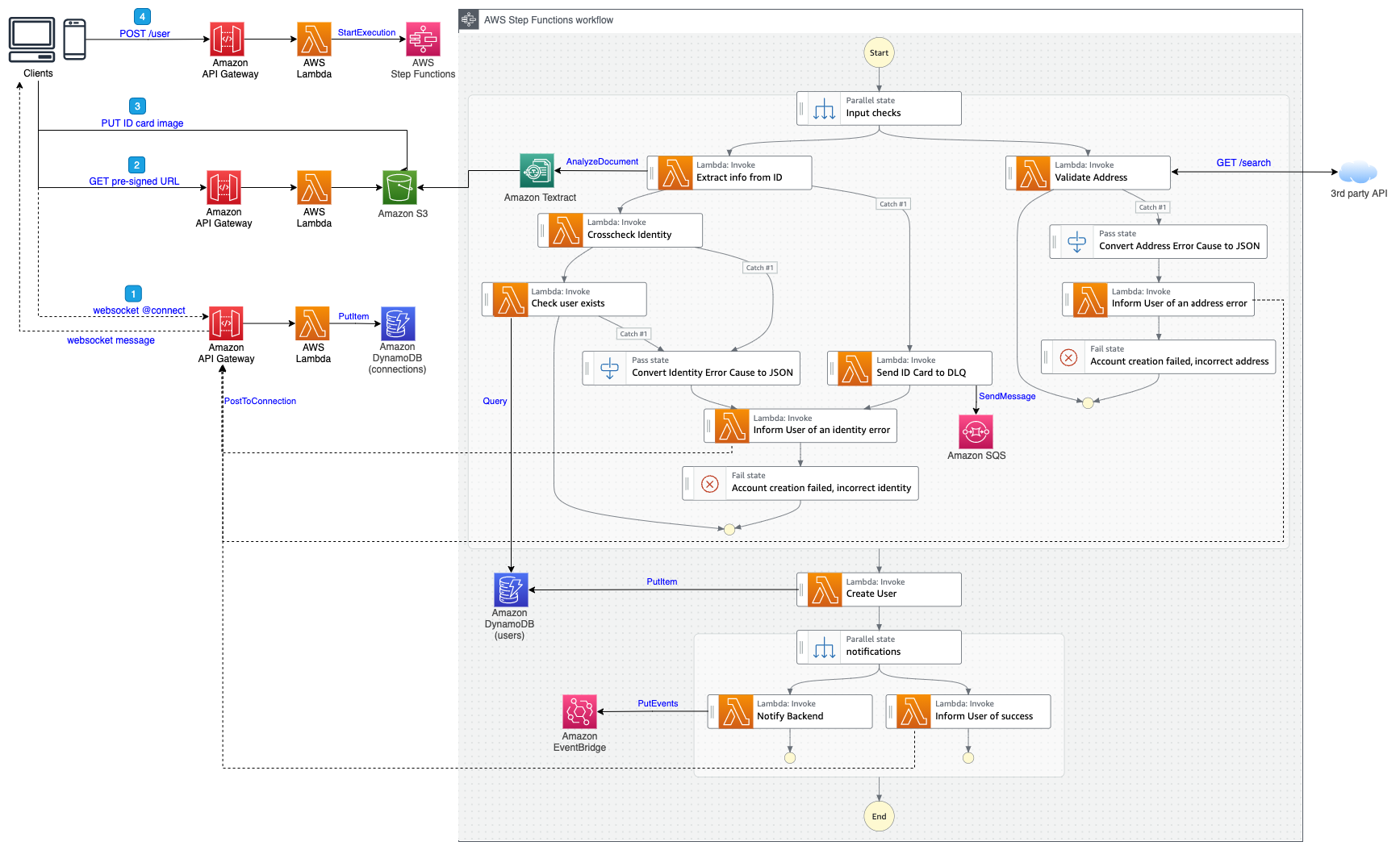
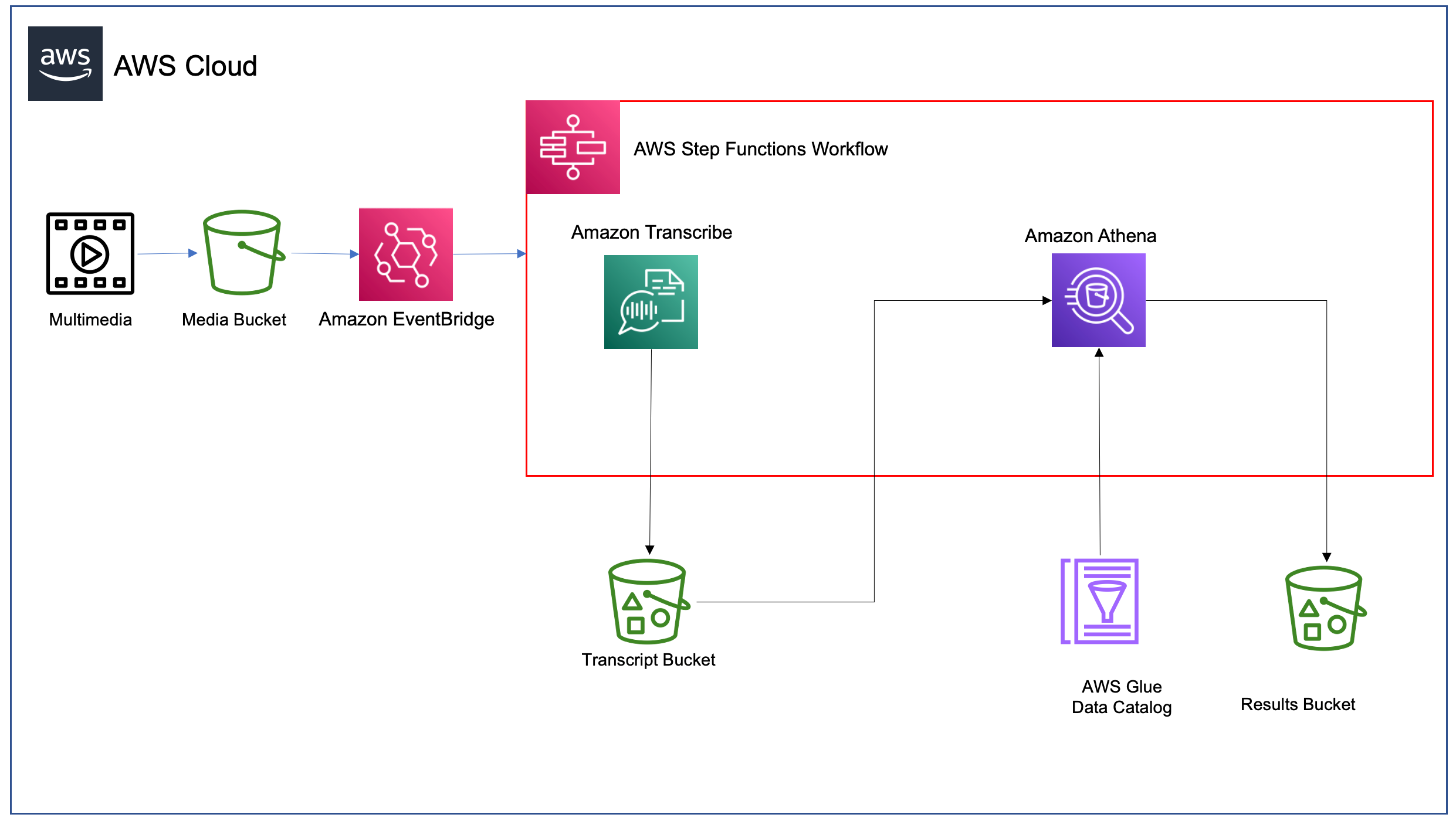
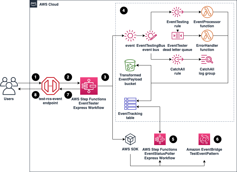
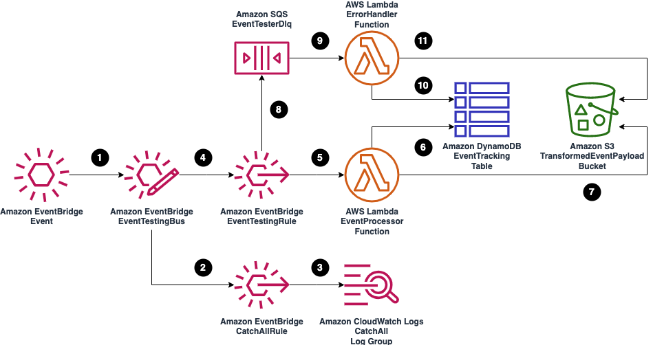
The following diagram shows the solution architecture.
Solution Overview
- You upload a media file to an Amazon S3 Media bucket.
- The media file upload to S3 triggers an EventBridge rule.
- The EventBridge rule starts the Step Functions state machine execution.
- The state machine invokes Amazon Transcribe to process the media file.
- The transcription output file is stored in the Amazon S3 Transcript bucket.
- The state machine invokes Athena to query the textual transcript for the filler phrase. This uses the AWS Glue table to describe the format of the transcription results file.
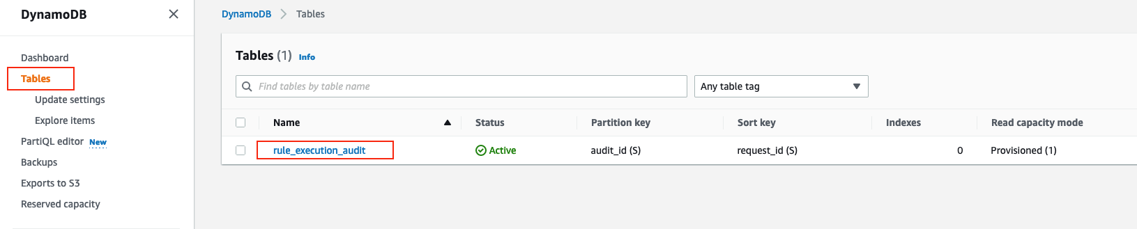
- The filler phrase count determined by Athena is returned and stored in the Amazon S3 Results bucket.
Prerequisites
- An AWS account and an AWS user or role with sufficient permissions to create the necessary resources.
- Access to the following AWS services: Step Functions, Amazon Transcribe, Athena, and Amazon S3.
- Latest version of the AWS Serverless Application Model (AWS SAM) CLI, which helps developers create and manage serverless applications in the AWS Cloud.
- Test media files (for example, the Official AWS Podcast).
Example walkthrough
- Clone the GitHub repository to your local machine.
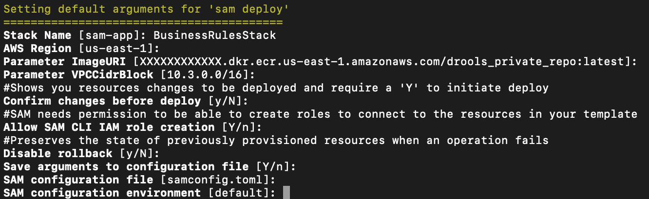
- Deploy the resources using AWS SAM. The deploy command processes the AWS SAM template file to create the necessary resources in AWS. Choose you-know as the stack name and the AWS Region that you want to deploy your solution to.
git clone https://github.com/aws-samples/aws-stepfunctions-examples.gitcd aws-stepfunctions-examples/sam/app-low-code-you-know-counter/
sam deploy --guidedUse the default parameters or replace with different values if necessary. For example, to get counts of a different filler phrase, replace the FillerPhrase parameter.
| GlueDatabaseYouKnowP | Name of the AWS Glue database to create. |
| AthenaTableName | Name of the AWS Glue table that is used by Athena to query the results. |
| FillerPhrase | The filler phrase to check. |
| AthenaQueryPreparedStatementName | Name of the Athena prepared statement used to run SQL queries on. |
| AthenaWorkgroup | Athena workgroup to use |
| AthenaDataCatalog | The data source for running the Athena queries |

SAM Deploy
Running the filler phrase counter
- Navigate to the Amazon S3 console and upload an mp3 or mp4 podcast recording to the bucket named bucket-{account number}-{Region}-you-know-media.
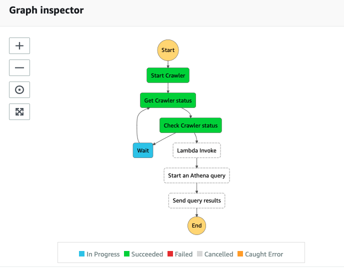
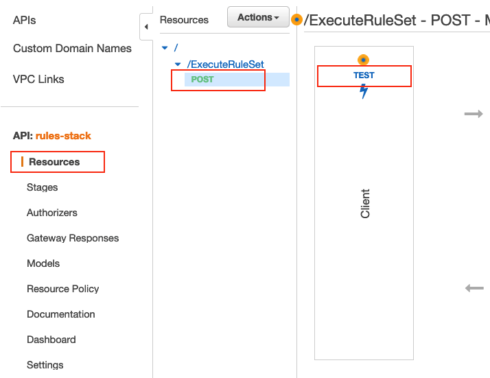
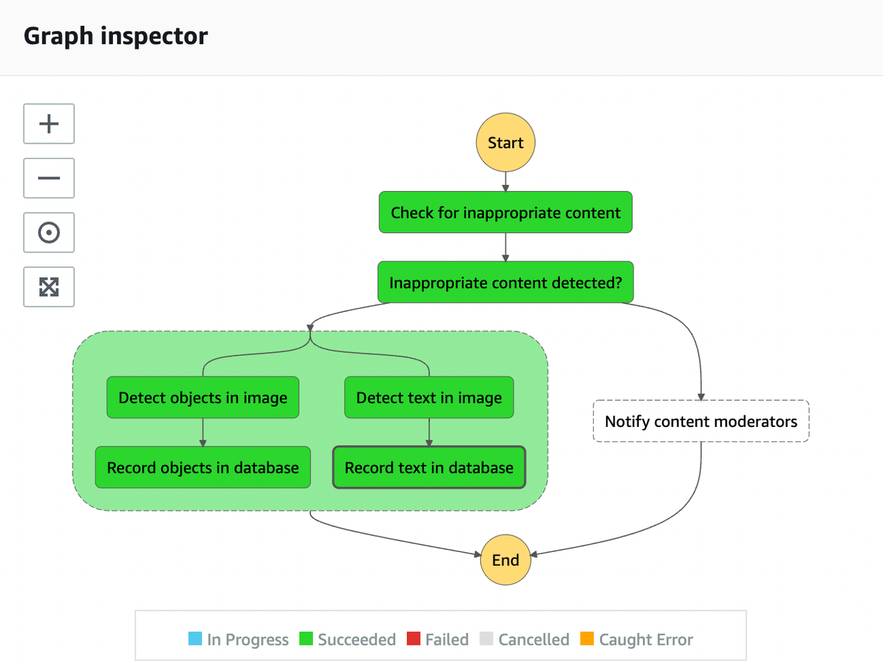
- Navigate to the Step Functions console. Choose the running state machine, and monitor the execution of the transcription state machine.
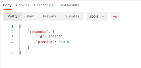
- When the execution completes successfully, select the QueryExecutionSuccess task to examine the output and see the filler phrase count.
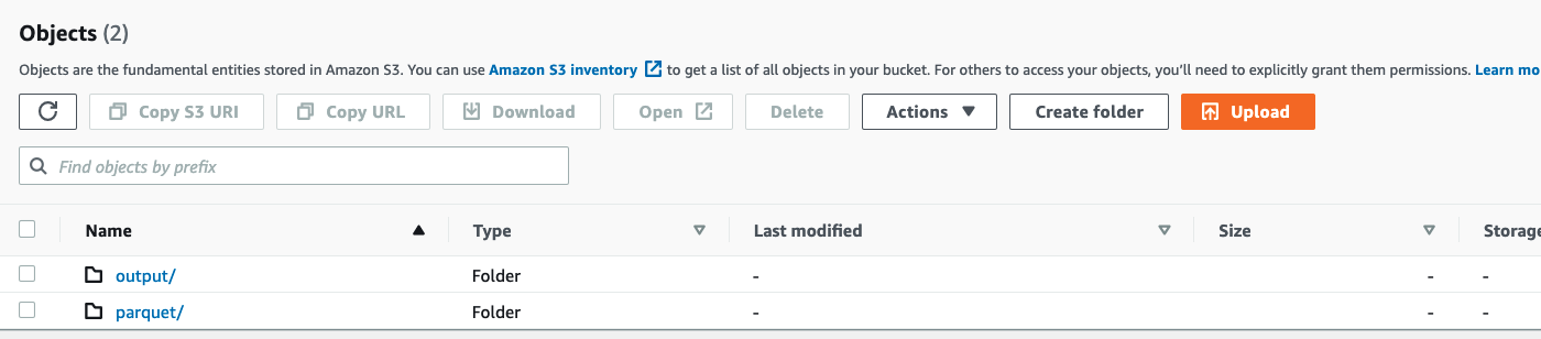
- Amazon Transcribe produces the transcript text of the media file. You can examine the output in the Results bucket. Using the S3 console, navigate to the bucket, choose the file matching the media file name and use ‘Query with S3 Select’ to view the content.
- If the transcription job does not execute, the state machine reports the failure and exits.

State Machine Execution

State Machine Output

State Machine Fail
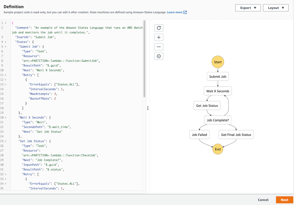
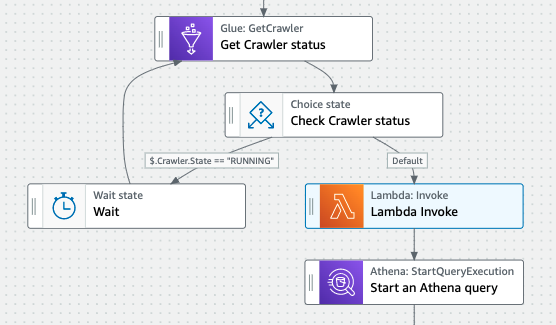
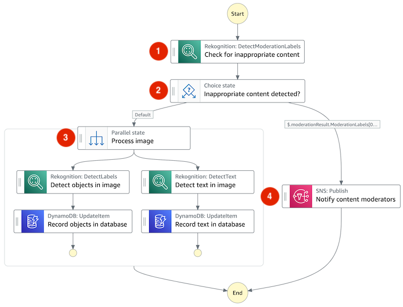
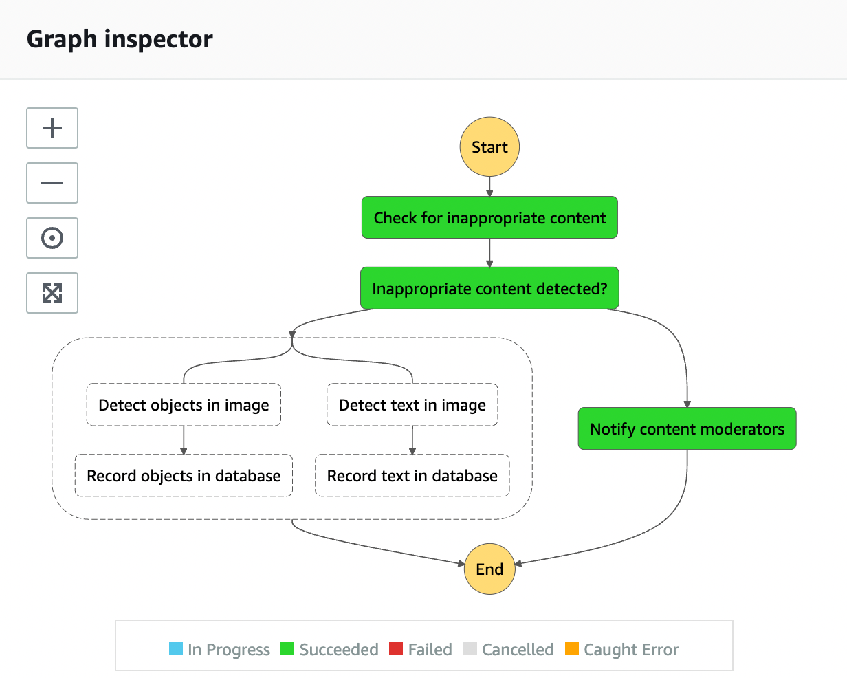
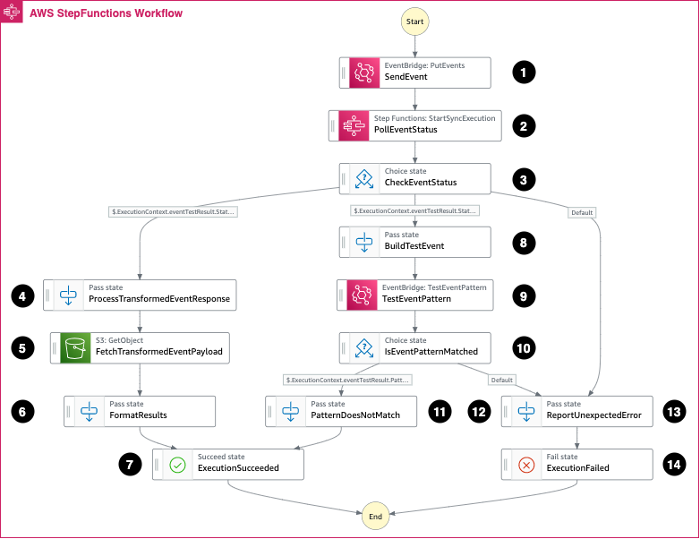
Exploring the state machine
The state machine orchestrates the transcription processing:

State Machine Explore
The StartTranscriptionJob task starts the transcription job. The Wait state adds a 60-second delay before checking the status of the transcription job. Until the status of the job changes to FAILED or COMPLETED, the choice state continues.
When the job successfully completes, the AthenaStartQueryExecutionUsingPreparedStatement task starts the Athena query, and stores the results in the S3 results bucket. The AthenaGetQueryResults task retrieves the count from the resultset.
The TranscribeMediaBucket holds the media files to be uploaded. The configuration sends the upload notification event to EventBridge:
   NotificationConfiguration:
     EventBridgeConfiguration:
       EventBridgeEnabled: true
The TranscribeResultsBucket has an associated policy to provide access to Amazon Transcribe. Athena stores the output from the queries performed by the state machine in the AthenaQueryResultsBucket .
When a media upload occurs, the YouKnowTranscribeStateMachine uses Step Functions’ native event integration to trigger an EventBridge rule. This contains an event object similar to:
{
  "version": "0",
  "id": "99a0cb40-4b26-7d74-dc59-c837f5346ac6",
  "detail-type": "Object Created",
  "source": "aws.s3",
  "account": "012345678901",
  "time": "2022-05-19T22:21:10Z",
  "region": "us-east-2",
  "resources": [
    "arn:aws:s3:::bucket-012345678901-us-east-2-you-know-media"
  ],
  "detail": {
    "version": "0",
    "bucket": {
      "name": "bucket-012345678901-us-east-2-you-know-media"
    },
    "object": {
      "key": "Podcase_Episode.m4a",
      "size": 202329,
      "etag": "624fce93a981f97d85025e8432e24f48",
      "sequencer": "006286C2D604D7A390"
    },
    "request-id": "B4DA7RD214V1QG3W",
    "requester": "012345678901",
    "source-ip-address": "172.0.0.1",
    "reason": "PutObject"
  }
}
The state machine allows you to prepare parameters and use the direct SDK integrations to start the transcription job by calling the Amazon Transcribe service’s API. This integration means you don’t have to write custom code to perform this function. The event triggering the state machine execution contains the uploaded media file location.
  StartTranscriptionJob:
	Type: Task
	Comment: Start a transcribe job on the provided media file
	Parameters:
	  Media:
		MediaFileUri.$: States.Format('s3://{}/{}', $.detail.bucket.name, $.detail.object.key)
	  TranscriptionJobName.$: "$.detail.object.key"
	  IdentifyLanguage: true
	  OutputBucketName: !Ref TranscribeResultsBucket
	Resource: !Sub 'arn:${AWS::Partition}:states:${AWS::Region}:${AWS::AccountId}:aws-sdk:transcribe:startTranscriptionJob'
The SDK uses aws-sdk:transcribe:getTranscriptionJob to get the status of the job.
  GetTranscriptionJob:
	Type: Task
	Comment: Retrieve the status of an Amazon Transcribe job
	Parameters:
	  TranscriptionJobName.$: "$.TranscriptionJob.TranscriptionJobName"
	Resource: !Sub 'arn:${AWS::Partition}:states:${AWS::Region}:${AWS::AccountId}:aws-sdk:transcribe:getTranscriptionJob'
	Next: TranscriptionJobStatus
The state machine uses a polling loop with a delay to check the status of the transcription job.
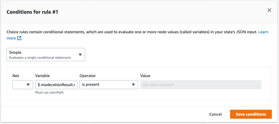
  TranscriptionJobStatus:
	Type: Choice
	Choices:
	- Variable: "$.TranscriptionJob.TranscriptionJobStatus"
	  StringEquals: COMPLETED
	  Next: AthenaStartQueryExecutionUsingPreparedStatement
	- Variable: "$.TranscriptionJob.TranscriptionJobStatus"
	  StringEquals: FAILED
	  Next: Failed
	Default: Wait
When the transcription job completes successfully, the filler phrase counting process begins.
An Athena prepared statement performs the query with the transcription job name as a runtime parameter. The AWS SDK starts the query and the state machine execution pauses, waiting for the results to return before progressing to the next state:
athena:startQueryExecution.syncWhen the query completes, Step Functions uses the SDK integration to retrieve the results using athena:getQueryResults:
athena:getQueryResultsIt creates an Athena prepared statement to pass the transcription jobname as a parameter for the query execution:
  ResultsQueryPreparedStatement:
    Type: AWS::Athena::PreparedStatement
    Properties:
      Description: Create a statement that allows the use of a parameter for specifying an Amazon Transcribe job name in the Athena query
      QueryStatement: !Sub >-
        select cardinality(regexp_extract_all(results.transcripts[1].transcript, '${FillerPhrase}')) AS item_count from "${GlueDatabaseYouKnow}"."${AthenaTableName}" where jobname like ?
      StatementName: !Ref AthenaQueryPreparedStatementName
      WorkGroup: !Ref AthenaWorkgroup
There are several opportunities to enhance this tool. For example, adding support for multiple filler phrases. You could build a larger application to upload media and retrieve the results. You could take advantage of Amazon Transcribe’s real-time transcription API to display the results while a presentation is in progress to provide immediate feedback to the presenter.
Cleaning up
- Navigate to the Amazon Transcribe console. Choose Transcription jobs in the left pane, select the jobs created by this example, and choose Delete.
- Navigate to the S3 console. In the Find buckets by name search bar, enter “you-know”. This shows the list of buckets created for this example. Choose each of the radio buttons next to the bucket individually and choose Empty.
- Use the following command to delete the stack, and confirm the stack deletion.

Cleanup Delete

Cleanup S3
sam deleteConclusion
Low-code applications can increase developer efficiency by reducing the amount of custom code required to build solutions. They can also enable non-developer roles to create automation to perform business functions by providing drag-and-drop style user interfaces.
This post shows how a low-code approach can build a tool chain using AWS services. The example processes media files to produce text transcripts and count the use of filler phrases in those transcripts. It shows how to process EventBridge data and how to invoke Amazon Transcribe and Athena using Step Functions state machines.
For more serverless learning resources, visit Serverless Land.


 ” to my colleagues, and have a coffee while asking all your serverless questions. You can find all the upcoming AWS Summits in the events section at the end of this post.