Post Syndicated from Kanti Chalasani original https://aws.amazon.com/blogs/big-data/how-the-georgia-data-analytics-center-built-a-cloud-analytics-solution-from-scratch-with-the-aws-data-lab/
This is a guest post by Kanti Chalasani, Division Director at Georgia Data Analytics Center (GDAC). GDAC is housed within the Georgia Office of Planning and Budget to facilitate governed data sharing between various state agencies and departments.
The Office of Planning and Budget (OPB) established the Georgia Data Analytics Center (GDAC) with the intent to provide data accountability and transparency in Georgia. GDAC strives to support the state’s government agencies, academic institutions, researchers, and taxpayers with their data needs. Georgia’s modern data analytics center will help to securely harvest, integrate, anonymize, and aggregate data.
In this post, we share how GDAC created an analytics platform from scratch using AWS services and how GDAC collaborated with the AWS Data Lab to accelerate this project from design to build in record time. The pre-planning sessions, technical immersions, pre-build sessions, and post-build sessions helped us focus on our objectives and tangible deliverables. We built a prototype with a modern data architecture and quickly ingested additional data into the data lake and the data warehouse. The purpose-built data and analytics services allowed us to quickly ingest additional data and deliver data analytics dashboards. It was extremely rewarding to officially release the GDAC public website within only 4 months.
A combination of clear direction from OPB executive stakeholders, input from the knowledgeable and driven AWS team, and the GDAC team’s drive and commitment to learning played a huge role in this success story. GDAC’s partner agencies helped tremendously through timely data delivery, data validation, and review.
We had a two-tiered engagement with the AWS Data Lab. In the first tier, we participated in a Design Lab to discuss our near-to-long-term requirements and create a best-fit architecture. We discussed the pros and cons of various services that can help us meet those requirements. We also had meaningful engagement with AWS subject matter experts from various AWS services to dive deeper into the best practices.
The Design Lab was followed by a Build Lab, where we took a smaller cross section of the bigger architecture and implemented a prototype in 4 days. During the Build Lab, we worked in GDAC AWS accounts, using GDAC data and GDAC resources. This not only helped us build the prototype, but also helped us gain hands-on experience in building it. This experience also helped us better maintain the product after we went live. We were able to continually build on this hands-on experience and share the knowledge with other agencies in Georgia.
Our Design and Build Lab experiences are detailed below.
Step 1: Design Lab
We wanted to stand up a platform that can meet the data and analytics needs for the Georgia Data Analytics Center (GDAC) and potentially serve as a gold standard for other government agencies in Georgia. Our objective with the AWS Data Design Lab was to come up with an architecture that meets initial data needs and provides ample scope for future expansion, as our user base and data volume increased. We wanted each component of the architecture to scale independently, with tighter controls on data access. Our objective was to enable easy exploration of data with faster response times using Tableau data analytics as well as build data capital for Georgia. This would allow us to empower our policymakers to make data-driven decisions in a timely manner and allow State agencies to share data and definitions within and across agencies through data governance. We also stressed on data security, classification, obfuscation, auditing, monitoring, logging, and compliance needs. We wanted to use purpose-built tools meant for specialized objectives.
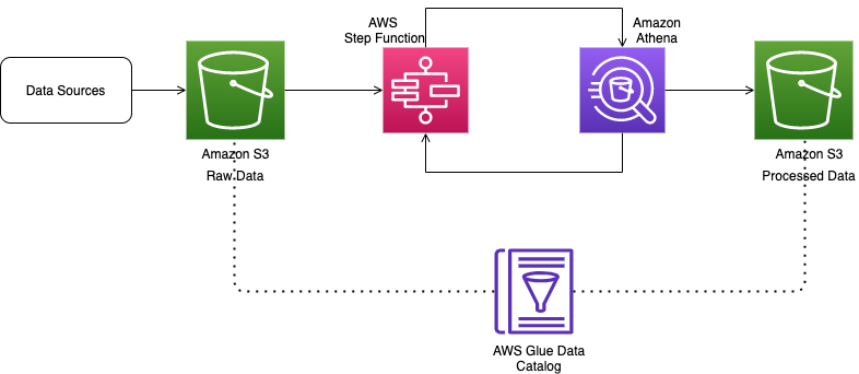
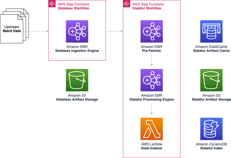
Over the course of the 2-day Design Lab, we defined our overall architecture and picked a scaled-down version to explore. The following diagram illustrates the architecture of our prototype.
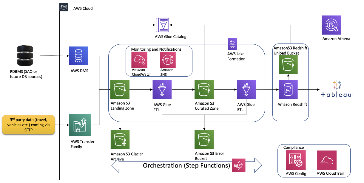
The architecture contains the following key components:
- Amazon Simple Storage Service (Amazon S3) for raw data landing and curated data staging.
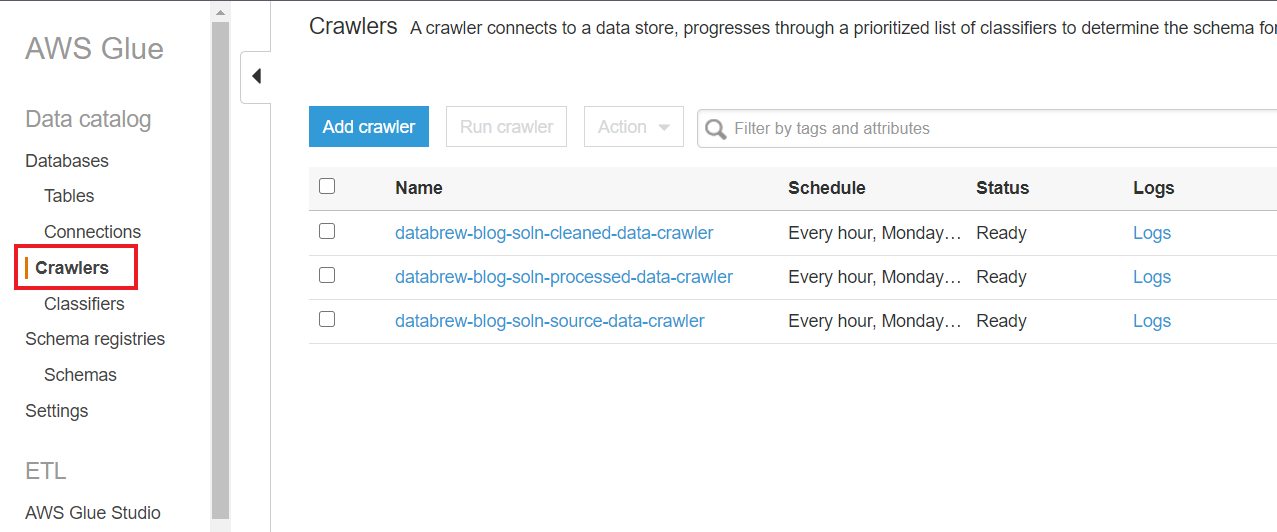
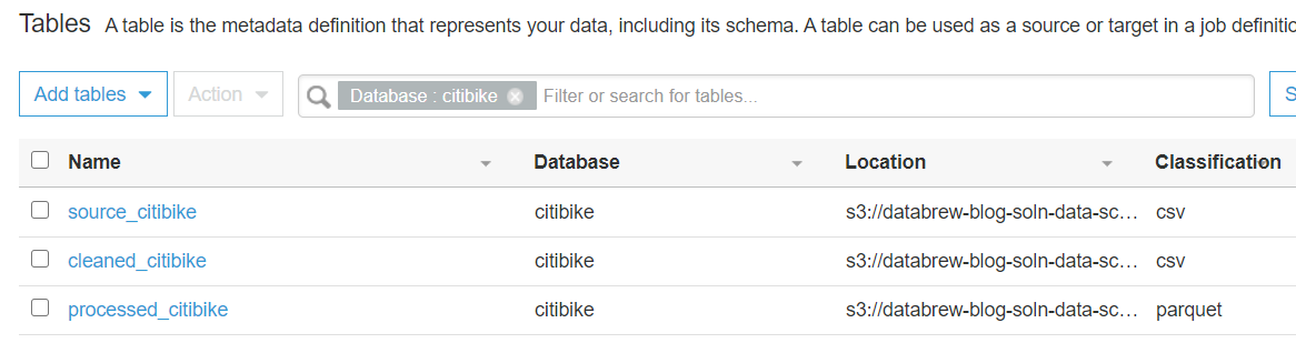
- AWS Glue for extract, transform, and load (ETL) jobs to move data from the Amazon S3 landing zone to Amazon S3 curated zone in optimal format and layout. We used an AWS Glue crawler to update the AWS Glue Data Catalog.
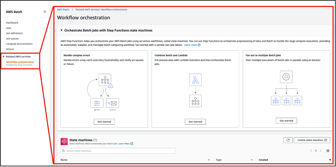
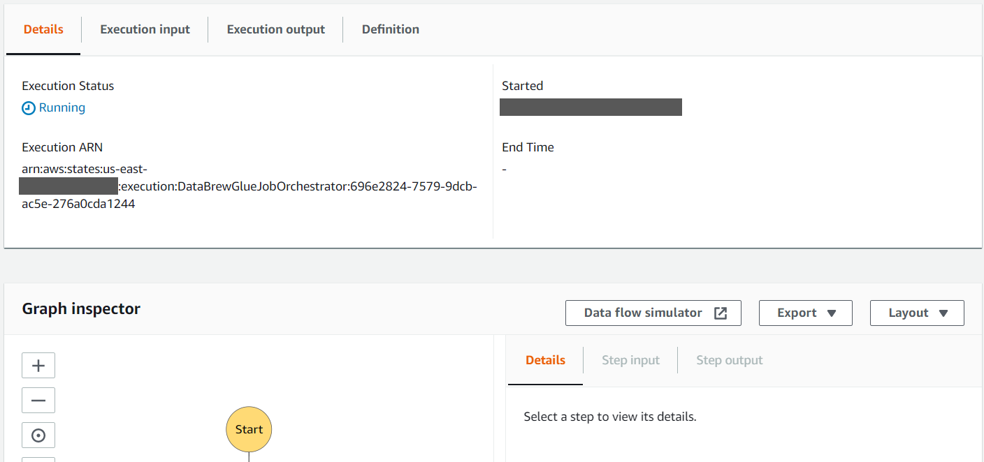
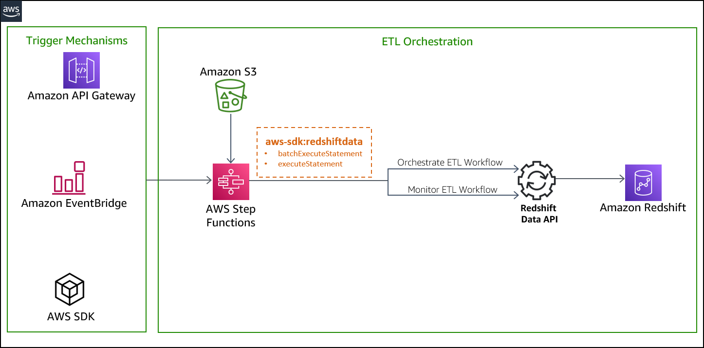
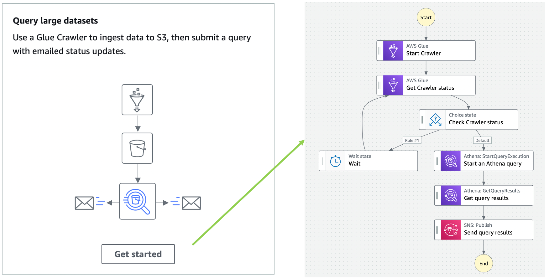
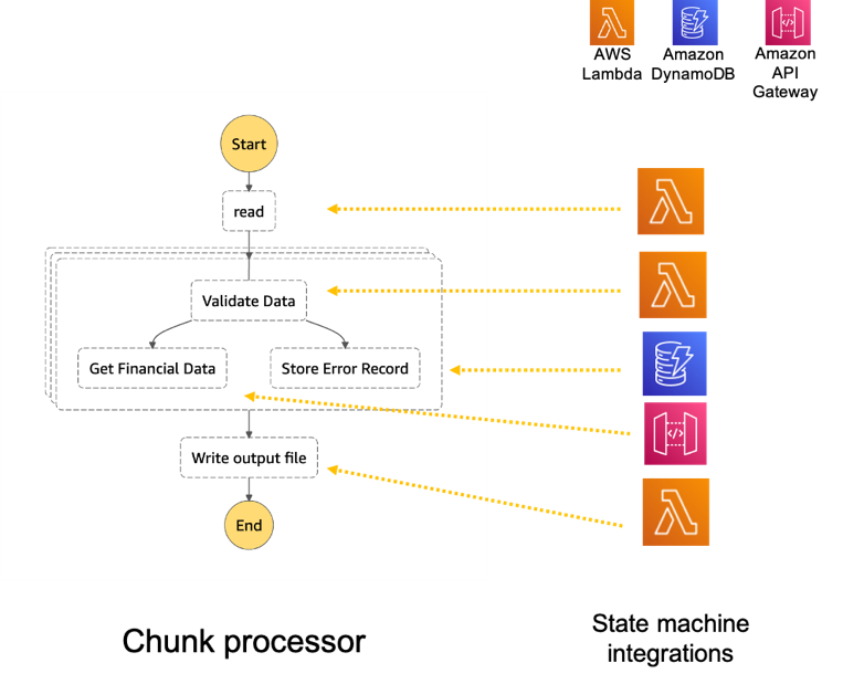
- AWS Step Functions for AWS Glue job orchestration.
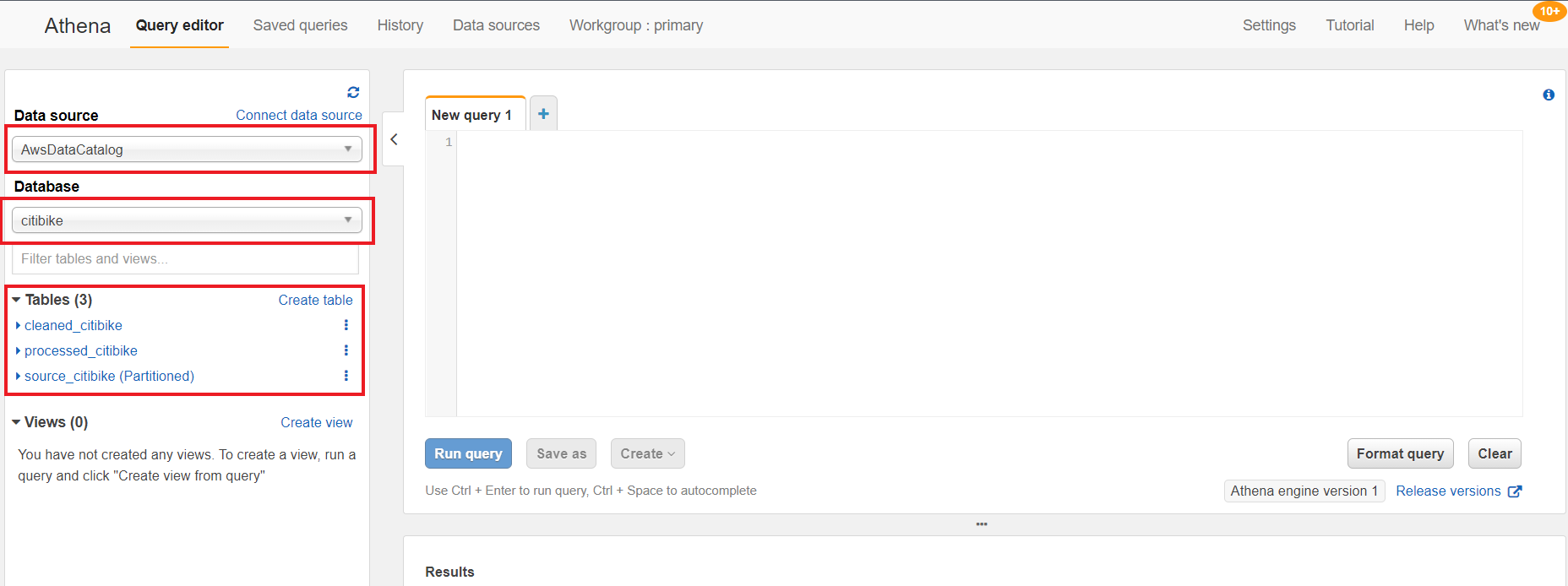
- Amazon Athena as a powerful tool for a quick and extensive SQL data analysis and to build a logical layer on the landing zone.
- Amazon Redshift to create a federated data warehouse with conformed dimensions and star schemas for consumption by Tableau data analytics.
Step 2: Pre-Build Lab
We started with planning sessions to build foundational components of our infrastructure: AWS accounts, Amazon Elastic Compute Cloud (Amazon EC2) instances, an Amazon Redshift cluster, a virtual private cloud (VPC), route tables, security groups, encryption keys, access rules, internet gateways, a bastion host, and more. Additionally, we set up AWS Identity and Access Management (IAM) roles and policies, AWS Glue connections, dev endpoints, and notebooks. Files were ingested via secure FTP, or from a database to Amazon S3 using AWS Command Line Interface (AWS CLI). We crawled Amazon S3 via AWS Glue crawlers to build Data Catalog schemas and tables for quick SQL access in Athena.
The GDAC team participated in Immersion Days for training in AWS Glue, AWS Lake Formation, and Amazon Redshift in preparation for the Build Lab.
We defined the following as the success criteria for the Build Lab:
- Create ETL pipelines from source (Amazon S3 raw) to target (Amazon Redshift). These ETL pipelines should create and load dimensions and facts in Amazon Redshift.
- Have a mechanism to test the accuracy of the data loaded through our pipelines.
- Set up Amazon Redshift in a private subnet of a VPC, with appropriate users and roles identified.
- Connect from AWS Glue to Amazon S3 to Amazon Redshift without going over the internet.
- Set up row-level filtering in Amazon Redshift based on user login.
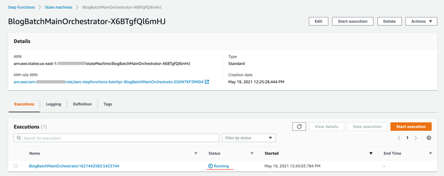
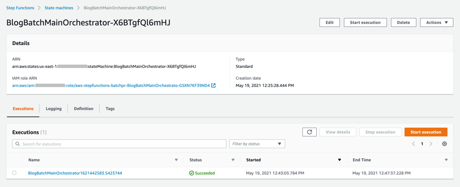
- Data pipelines orchestration using Step Functions.
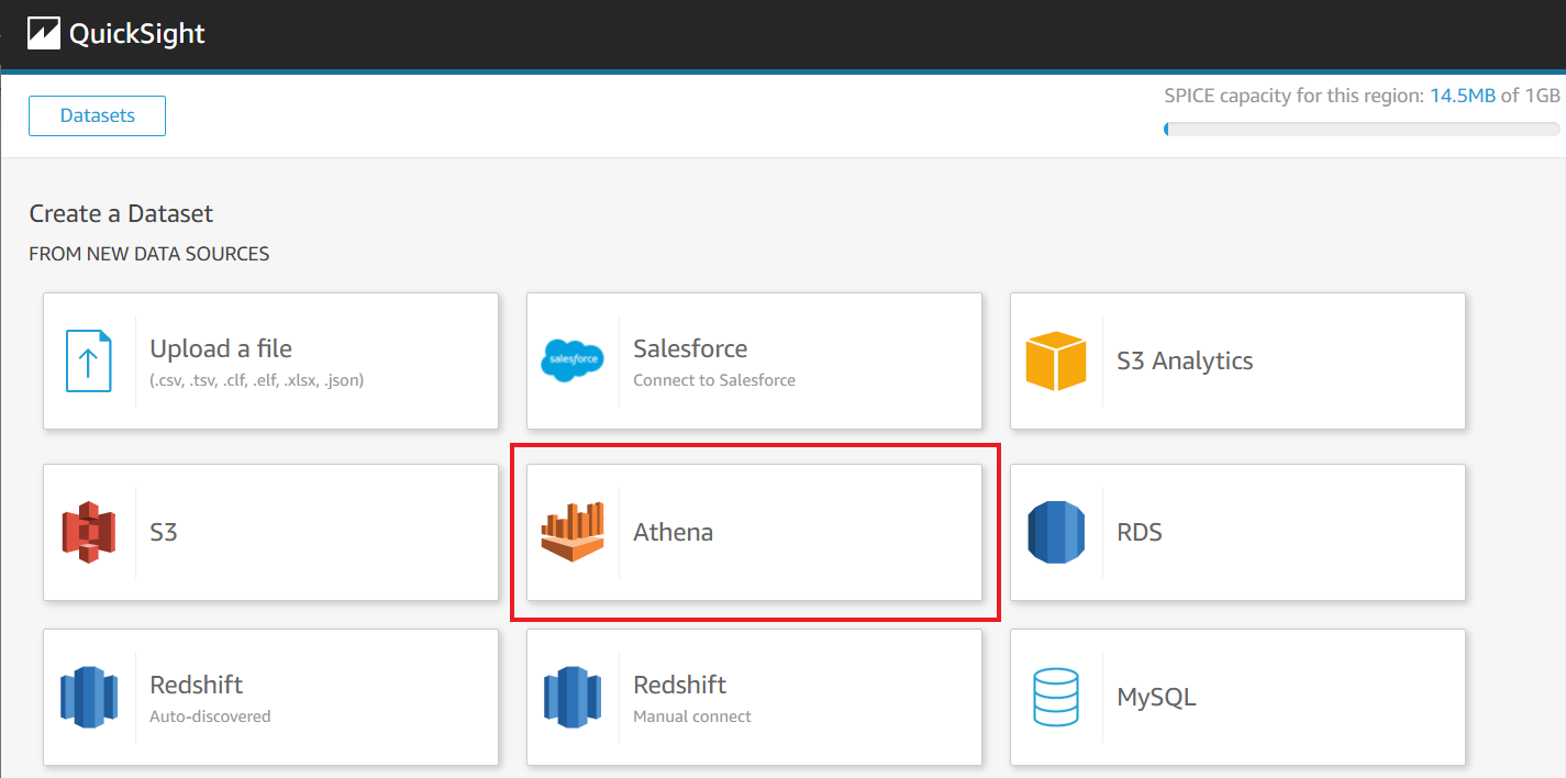
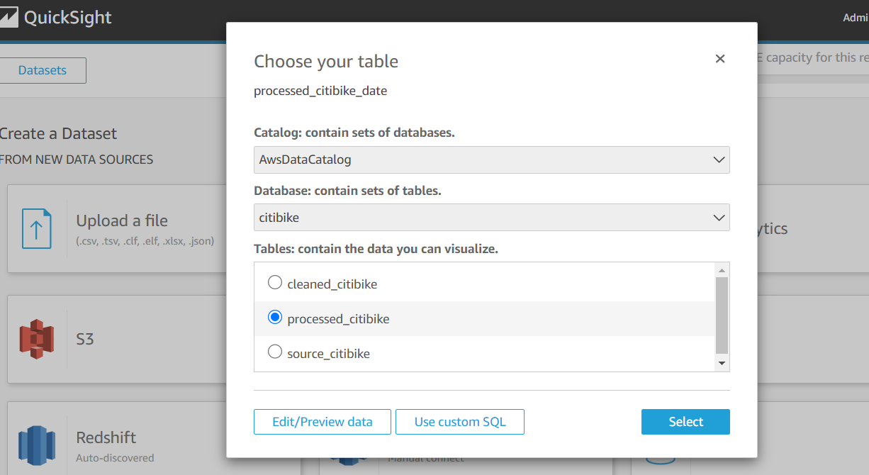
- Build and publish Tableau analytics with connections to our star schema in Amazon Redshift.
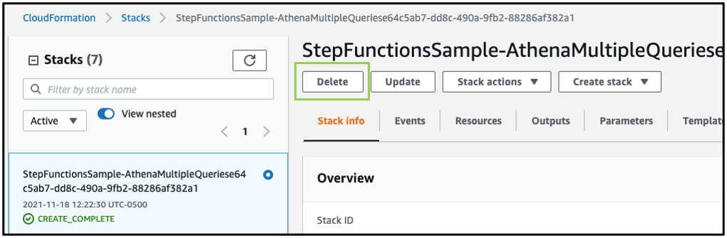
- Automate the deployment using AWS CloudFormation.
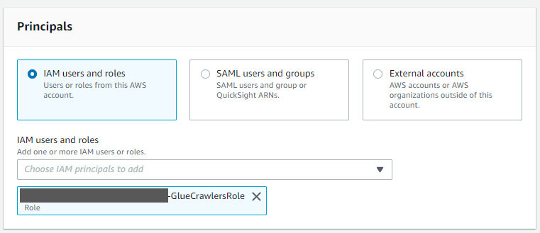
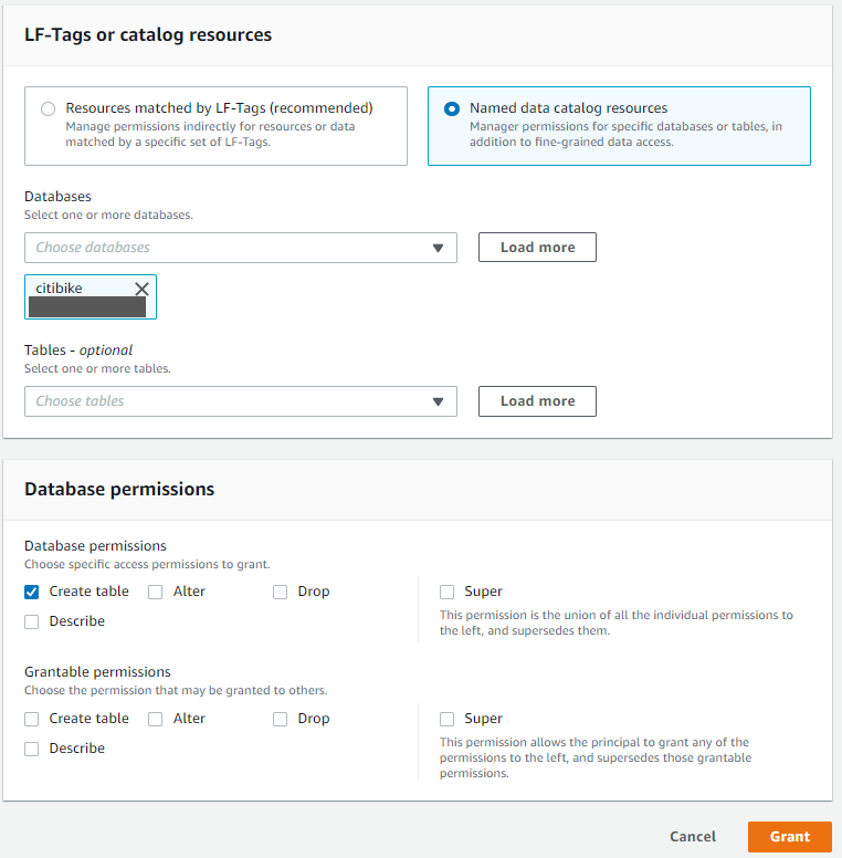
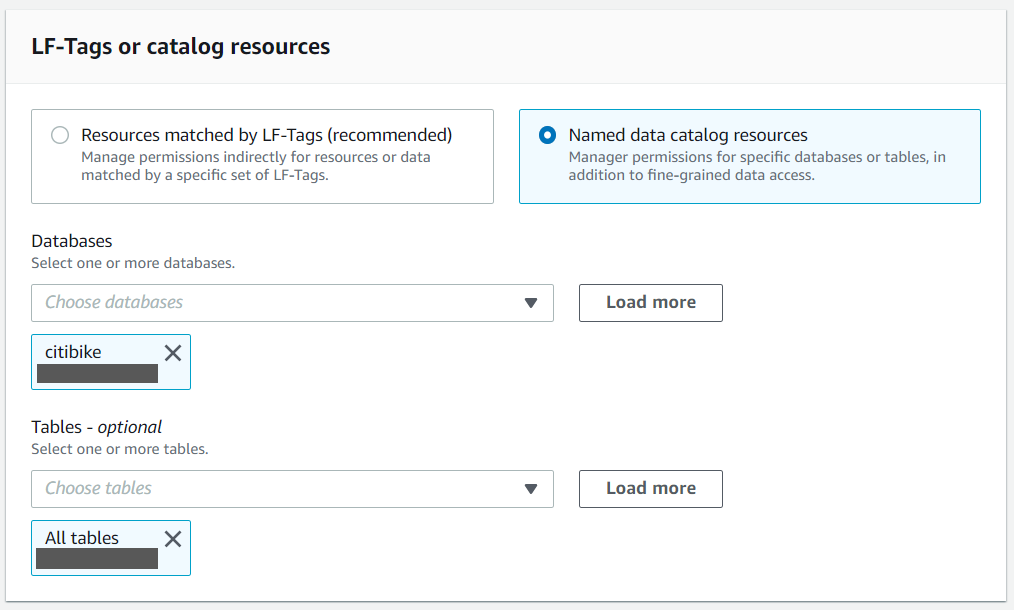
- Set up column-level security for the data in Amazon S3 using Lake Formation. This allows for differential access to data based on user roles to users using both Athena and Amazon Redshift Spectrum.
Step 3: Four-day Build Lab
Following a series of implementation sessions with our architect, we formed the GDAC data lake and organized downstream data pulls for the data warehouse with governed data access. Data was ingested in the raw data landing lake and then curated into a staging lake, where data was compressed and partitioned in Parquet format.
It was empowering for us to build PySpark Extract Transform Loads (ETL) AWS Glue jobs with our meticulous AWS Data Lab architect. We built reusable glue jobs for the data ingestion and curation using the code snippets provided. The days were rigorous and long, but we were thrilled to see our centralized data repository come into fruition so rapidly. Cataloging data and using Athena queries proved to be a fast and cost-effective way for data exploration and data wrangling.
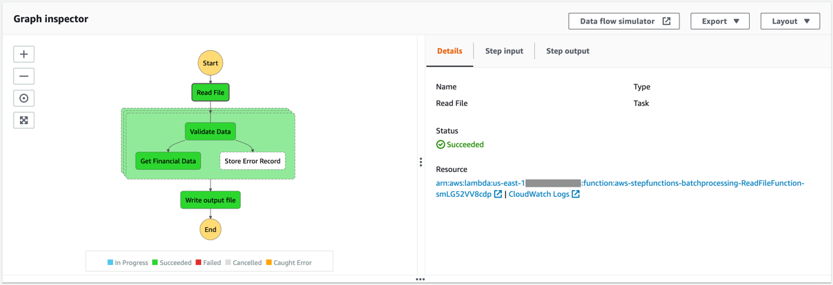
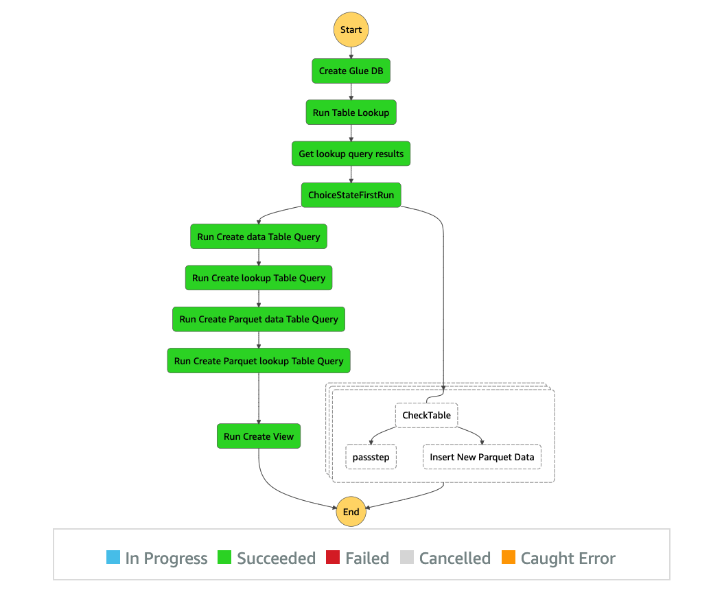
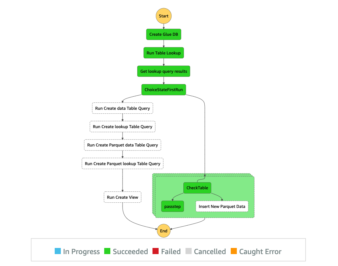
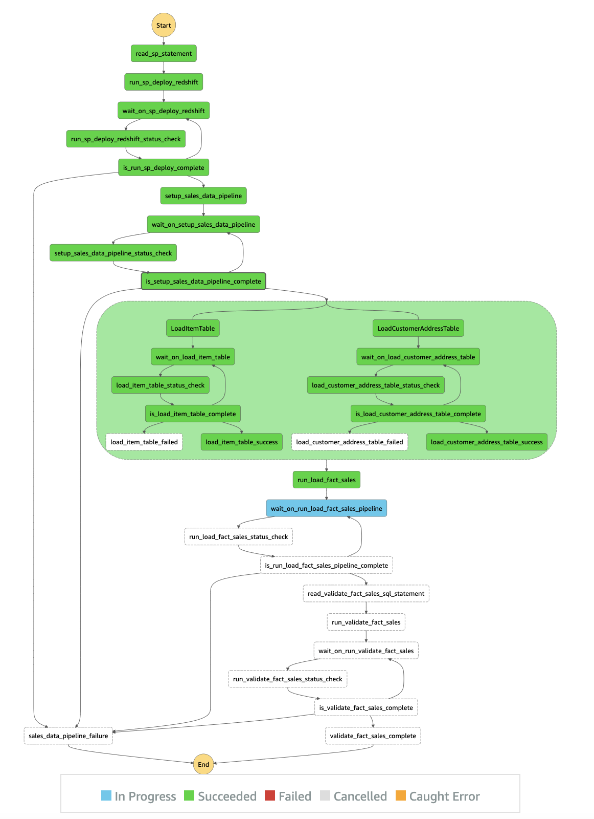
The serverless orchestration with Step Functions allowed us to put AWS Glue jobs into a simple readable data workflow. We spent time designing for performance and partitioning data to minimize cost and increase efficiency.
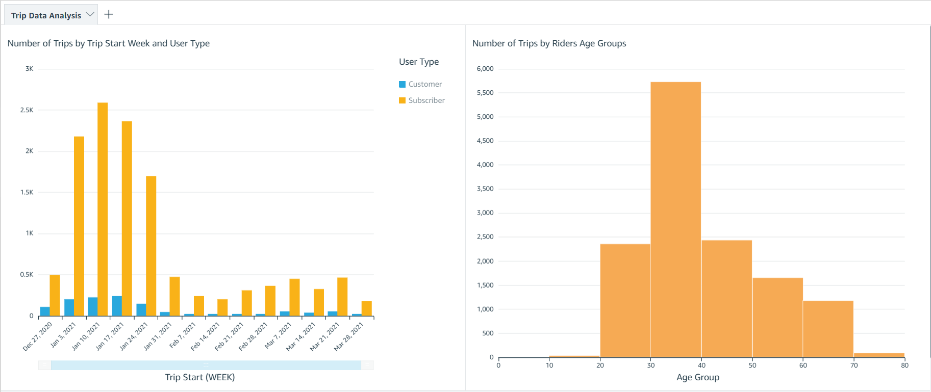
Database access from Tableau and SQL Workbench/J were set up for my team. Our excitement only grew as we began building data analytics and dashboards using our dimensional data models.
Step 4: Post-Build Lab
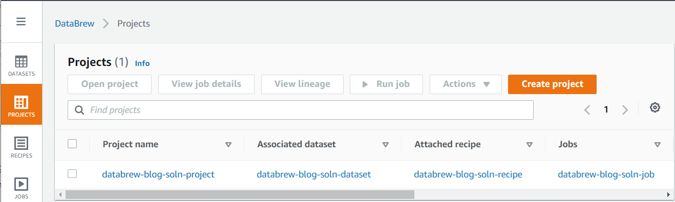
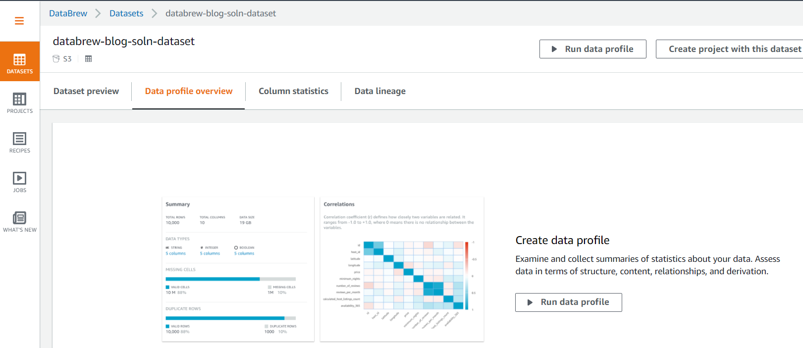
During our post-Build Lab session, we closed several loose ends and built additional AWS Glue jobs for initial and historic loads and append vs. overwrite strategies. These strategies were picked based on the nature of the data in various tables. We returned for a second Build Lab to work on building data migration tasks from Oracle Database via VPC peering, file processing using AWS Glue DataBrew, and AWS CloudFormation for automated AWS Glue job generation. If you have a team of 4–8 builders looking for a fast and easy foundation for a complete data analytics system, I would highly recommend the AWS Data Lab.
Conclusion
All in all, with a very small team we were able to set up a sustainable framework on AWS infrastructure with elastic scaling to handle future capacity without compromising quality. With this framework in place, we are moving rapidly with new data feeds. This would not have been possible without the assistance of the AWS Data Lab team throughout the project lifecycle. With this quick win, we decided to move forward and build AWS Control Tower with multiple accounts in our landing zone. We brought in professionals to help set up infrastructure and data compliance guardrails and security policies. We are thrilled to continually improve our cloud infrastructure, services and data engineering processes. This strong initial foundation has paved the pathway to endless data projects in Georgia.
About the Author
 Kanti Chalasani serves as the Division Director for the Georgia Data Analytics Center (GDAC) at the Office of Planning and Budget (OPB). Kanti is responsible for GDAC’s data management, analytics, security, compliance, and governance activities. She strives to work with state agencies to improve data sharing, data literacy, and data quality through this modern data engineering platform. With over 26 years of experience in IT management, hands-on data warehousing, and analytics experience, she thrives for excellence.
 Vishal Pathak is an AWS Data Lab Solutions Architect. Vishal works with customers on their use cases, architects solutions to solve their business problems, and helps them build scalable prototypes. Prior to his journey with AWS, Vishal helped customers implement BI, data warehousing, and data lake projects in the US and Australia.


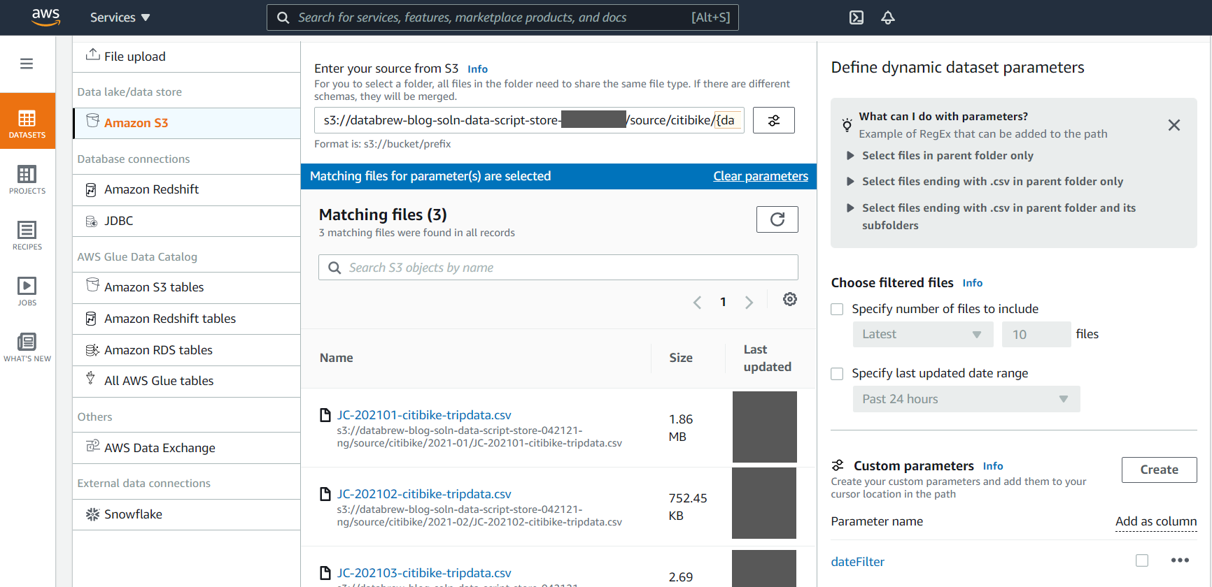
 Note the template parameters:


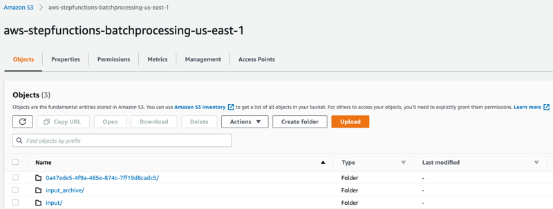
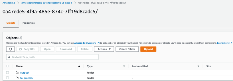
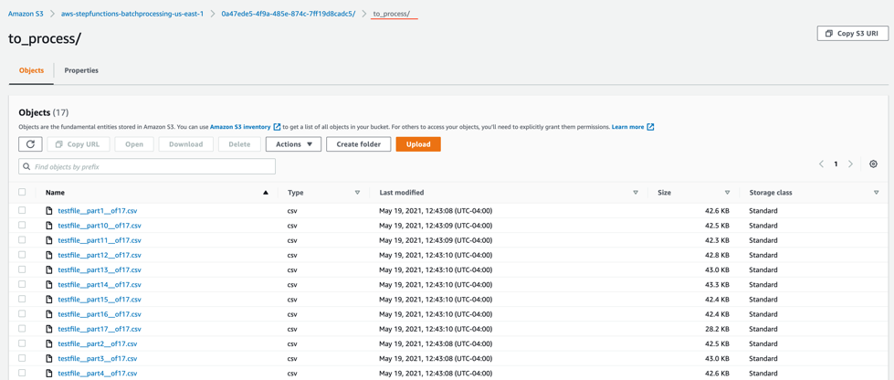
 to_process – This folder contains all the split objects from the original input file.