Tag Archives: Amazon Managed Workflows for Apache Airflow (Amazon MWAA)

Use a reusable ETL framework in your AWS lake house architecture

Post Syndicated from Ashutosh Dubey original https://aws.amazon.com/blogs/architecture/use-a-reusable-etl-framework-in-your-aws-lake-house-architecture/

Data lakes and lake house architectures have become an integral part of a data platform for any organization. However, you may face multiple challenges while developing a lake house platform and integrating with various source systems. In this blog, we will address these challenges and show how our framework can help mitigate these issues.

Lake house architecture using AWS

Figure 1 shows a typical lake house implementation in an Amazon Web Services (AWS) environment.

Typical lake house implementation in AWS

Figure 1. Typical lake house implementation in AWS

In this diagram we have five layers. The number of layers and names can vary per environmental requirements, so check recommended data layers for more details.

  1. Landing layer. This is where all source files are dropped in their original format.
  2. Raw layer. This is where all source files are converted and stored in a common parquet format.
  3. Stage layer. This is where we maintain a history of dimensional tables as Slowly Changing Dimension Type 2 (SCD2). Apache Hudi is used for SCD2 in the Amazon Simple Storage Service (Amazon S3) bucket, and an AWS Glue job is used to write to Hudi tables. AWS Glue is used to perform any extract, transform, and load (ETL) job to move, cleanse, validate, or transform files between any two layers. For details, see using the Hudi framework in AWS Glue.
  4. Presentation layer. This is where data is being cleansed, validated, and transformed, using an AWS Glue job, in accordance with business requirements.
  5. Data warehouse layer. Amazon Redshift is being used as the data warehouse where the curated or cleansed data resides. We can either copy the data using an AWS Glue python shell job, or create a Spectrum table out of the Amazon S3 location.

The data lake house architecture shows two types of data ingestion patterns, push and pull. In the pull-based ingestion, services like AWS Glue or AWS Lambda are used to pull data from sources like databases, APIs, or flat files into the data lake. In the push-based pattern, third-party sources can directly upload files into a landing Amazon S3 bucket in the data lake. Amazon Managed Workflows for Apache Airflow (Amazon MWAA) is used to orchestrate data pipelines that move data from the source systems into a data warehouse. Amazon EventBridge is used to schedule the Airflow directed acyclic graph (DAG) data pipelines. Amazon RDS for PostgreSQL is used to store metadata for configuration of the data pipelines. A data lake architecture with these capabilities provides a scalable, reliable, and efficient solution for data pipelines.

Data pipeline challenges

Maintaining data pipelines in a large lake house environment can be quite challenging. There are a number of hurdles one faces regularly. Creating individual AWS Glue jobs for each task in every Airflow DAG can lead to hundreds of AWS Glue jobs to manage. Error handling and job restarting gets increasingly more complex as the number of pipelines grows. Developing a new data pipeline from scratch takes time, due to the boilerplate code involved. The production support team can find it challenging to monitor and support such a large number of data pipelines. Data platform monitoring becomes arduous at that scale. Ensuring overall maintainability, robustness, and governability of data pipelines in a lake house is a constant struggle.

The benefits of a data pipeline framework

Having a data pipeline framework can significantly reduce the effort required to build data pipelines. This framework should be able to create a lake house environment that is easy to maintain and manage. It should also increase the reusability of code across data pipelines. Effective error handling and recovery mechanisms in the framework should make the data pipelines robust. Support for various data ingestion patterns like batch, micro batch, and streaming should make the framework versatile. A framework with such capabilities will help you build scalable, reliable, and flexible data pipelines, with reduced time and effort.

Reusable ETL framework

In a metadata-driven reusable framework, we have pre-created templates for different purposes. Metadata tables are used to configure the data pipelines.

Figure 2 shows the architecture of this framework:

Reusable ETL framework architecture

Figure 2. Reusable ETL framework architecture

In this framework, there are pre-created AWS Glue templates for different purposes, like copying files from SFTP to landing bucket, fetching rows from a database, converting file formats in landing to parquet in the raw layer, writing to Hudi tables, copying parquet files to Redshift tables, and more.

These templates are stored in a template bucket, and details of all templates are maintained in a template config table with a template_id in Amazon Relational Database Service (Amazon RDS). Each data pipeline (Airflow DAG) is represented as a flow_id in the main job config table. Each flow_id can have one or more tasks, and each task refers to a template_id. This framework can support both the type of ingestions—pull-based (scheduled pipelines) and push-based (initiated pipelines). The following steps show the detailed flow of the pipeline in Figure 2.

  1. To schedule a pipeline, the “Scheduled DAG Invoker Lambda” is scheduled in EventBridge, with flow_id of the pipeline as the parameter.
  2. The source drops files in a landing bucket.
  3. An event is initiated and calls the “Triggered DAG Invoker” Lambda. This Lambda function gets the file name from the event to call the Airflow API.
  4. A Lambda function queries an RDS metadata table with the parameter to get the DAG name.
  5. Both of the Lambda functions call the Airflow API to start the DAG.
  6. The Airflow webserver locates the DAG from the S3 location and passes it to the executor.
  7. The DAG is initiated.
  8. The DAG calls the functions in the common util python script with all required parameters.
  9. For any pipeline, the util script gets all the task details from the metadata table, along with the AWS Glue template name and location.
  10. For any database or API connectivity, the util function gets the secret credentials from AWS Secrets Manager based on the secret_id.
  11. The AWS Glue template file from the S3 location starts the AWS Glue job using Boto3 API by passing the required parameters. Once the AWS Glue job completes successfully, it deletes the job.
  12. If the pipeline contains any Lambda calls, the util script calls the Lambda function as per the configuration parameter.
  13. If the AWS Glue job fails due to any error in Step #11, the script captures the error message and sends an Amazon Simple Notification Service (Amazon SNS) notification.

For developing any new pipeline, the developer must identify the number of tasks that need to be created for the DAG. Identify which template can be used for which task, and insert configuration entries to the metadata tables accordingly. If there is no template available, create a new template to reuse later. Finally, create the Airflow DAG script and place it in the DAG location.

Conclusion

The proposed framework leverages AWS native services to provide a scalable and cost-effective solution. It allows faster development due to reusable components. You can dynamically generate and delete AWS Glue jobs as needed. This framework enables jobs tracking by configuration tables, supports error handling, and provides email notification. You can create scheduled and event-driven data pipelines to ingest data from various sources in different formats. And you can tune the performance and cost of AWS Glue jobs, by updating configuration parameters without changing any code.

A reusable framework is a great practice for any development project, as it improves time to market and standardizes development patterns in a team. This framework can be used in any AWS data lake or lake house environments with any number of data layers. This makes pipeline development faster, and error handing and support easier. You can enhance and customize even further to have more features like data reconciliation, micro-batch pipelines, and more.

Further reading:

Introducing Apache Airflow version 2.6.3 support on Amazon MWAA

Post Syndicated from Hernan Garcia original https://aws.amazon.com/blogs/big-data/introducing-apache-airflow-version-2-6-3-support-on-amazon-mwaa/

Amazon Managed Workflows for Apache Airflow (Amazon MWAA) is a managed orchestration service for Apache Airflow that makes it simple to set up and operate end-to-end data pipelines in the cloud. Trusted across various industries, Amazon MWAA helps organizations like Siemens, ENGIE, and Choice Hotels International enhance and scale their business workflows, while significantly improving security and reducing infrastructure management overhead.

Today, we are announcing the availability of Apache Airflow version 2.6.3 environments. If you’re currently running Apache Airflow version 2.x, you can seamlessly upgrade to v2.6.3 using in-place version upgrades, thereby retaining your workflow run history and environment configurations.

In this post, we delve into some of the new features and capabilities of Apache Airflow v2.6.3 and how you can set up or upgrade your Amazon MWAA environment to accommodate this version as you orchestrate your workflows in the cloud at scale.

New feature: Notifiers

Airflow now gives you an efficient way to create reusable and standardized notifications to handle systemic errors and failures. Notifiers introduce a new object in Airflow, designed to be an extensible layer for adding notifications to DAGs. This framework can send messages to external systems when a task instance or an individual DAG run changes its state. You can build notification logic from a new base object and call it directly from your DAG files. The BaseNotifier is an abstract class that provides a basic structure for sending notifications in Airflow using the various on_*__callback. It is intended for providers to extend and customize this for their specific needs.

Using this framework, you can build custom notification logic directly within your DAG files. For instance, notifications can be sent through email, Slack, or Amazon Simple Notification Service (Amazon SNS) based on the state of a DAG (on_failure, on_success, and so on). You can also create your own custom notifier that updates an API or posts a file to your storage system of choice.

For details on how to create and use a notifier, refer to Creating a notifier.

New feature: Managing tasks stuck in a queued state

Apache Airflow v2.6.3 brings a significant improvement to address the long-standing issue of tasks getting stuck in the queued state when using the CeleryExecutor. In a typical Apache Airflow workflow, tasks progress through a lifecycle, moving from the scheduled state to the queued state, and eventually to the running state. However, tasks can occasionally remain in the queued state longer than expected due to communication issues among the scheduler, the executor, and the worker. In Amazon MWAA, customers have experienced such tasks being queued for up to 12 hours due to how it utilizes the native integration of Amazon Simple Queue Service (Amazon SQS) with CeleryExecutor.

To mitigate this issue, Apache Airflow v2.6.3 introduced a mechanism that checks the Airflow database for tasks that have remained in the queued state beyond a specified timeout, defaulting to 600 seconds. This default can be modified using the environment configuration parameter scheduler.task_queued_timeout. The system then retries such tasks if retries are still available or fails them otherwise, ensuring that your data pipelines continue to function smoothly.

Notably, this update deprecates the previously used celery.stalled_task_timeout and celery.task_adoption_timeout settings, and consolidates their functionalities into a single configuration, scheduler.task_queued_timeout. This enables more effective management of tasks that remain in the queued state. Operators can also configure scheduler.task_queued_timeout_check_interval, which controls how frequently the system checks for tasks that have stayed in the queued state beyond the defined timeout.

For details on how to use task_queued_timeout, refer to the official Airflow documentation.

New feature: A new continuous timetable and support for continuous schedule

With prior versions of Airflow, to run a DAG continuously in a loop, you had to use the TriggerDagRunOperator to rerun the DAG after the last task is finished. With Apache Airflow v2.6.3, you can now run a DAG continuously with a predefined timetable. The simplifies scheduling for continual DAG runs. The new ContinuousTimetable construct will create one continuous DAG run, respecting start_date and end_date, with the new run starting as soon as the previous run has completed, regardless of whether the previous run has succeeded or failed. Using a continuous timetable is especially useful when sensors are used to wait for highly irregular events from external data tools.

You can bound the degree of parallelism to ensure that only one DAG is running at any given time with the max_active_runs parameter:

@dag(
    start_date=datetime(2023, 5, 9),
    schedule="@continuous",
    max_active_runs=1,  
    catchup=False,
)

New feature: Trigger the DAG UI extension with flexible user form concept

Prior to Apache Airflow v2.6.3, you could provide parameters in JSON structure through the Airflow UI for custom workflow runs. You had to model, check, and understand the JSON and enter parameters manually without the option to validate them before triggering a workflow. With Apache Airflow v2.6.3, when you choose Trigger DAG w/ config, a trigger UI form is rendered based on the predefined DAG Params. For your ad hoc, testing, or custom runs, this simplifies the DAG’s parameter entry. If the DAG has no parameters defined, a JSON entry mask is shown. The form elements can be defined with the Param class and attributes define how a form field is displayed.

For an example DAG the following form is generated by DAG Params.

Set Up a New Apache Airflow v2.6.3 Environment

You can set up a new Apache Airflow v2.6.3 environment in your account and preferred Region using the AWS Management Console, API, or AWS Command Line Interface (AWS CLI). If you’re adopting infrastructure as code (IaC), you can automate the setup using either AWS CloudFormation, the AWS Cloud Development Kit (AWS CDK), or Terraform scripts.

When you have successfully created an Apache Airflow v2.6.3 environment in Amazon MWAA, the following packages are automatically installed on the scheduler and worker nodes along with other provider packages:

apache-airflow-providers-amazon==8.2.0

python==3.10.8

For a complete list of provider packages installed, refer to Apache Airflow provider packages installed on Amazon MWAA environments.

Upgrade from older versions of Apache Airflow to Apache Airflow v2.6.3

You can perform in-place version upgrades of your existing Amazon MWAA environments to update your older Apache Airflow v2.x-based environments to v2.6.3. To learn more about in-place version upgrades, refer to Upgrading the Apache Airflow version or Introducing in-place version upgrades with Amazon MWAA.

Conclusion

In this post, we talked about some of the new features of Apache Airflow v2.6.3 and how you can get started using them in Amazon MWAA. Try out these new features like notifiers and continuous timetables, and other enhancements to improve your data orchestration pipelines.

For additional details and code examples on Amazon MWAA, visit the Amazon MWAA User Guide  and the Amazon MWAA examples GitHub repo.

Apache, Apache Airflow, and Airflow are either registered trademarks or trademarks of the Apache Software Foundation in the United States and/or other countries.


About the Authors

Hernan Garcia is a Senior Solutions Architect at AWS, based out of Amsterdam, working in the Financial Services Industry since 2018. He specializes in application modernization and supports his customers in the adoption of cloud operating models and serverless technologies.

Parnab Basak is a Solutions Architect and a Serverless Specialist at AWS. He specializes in creating new solutions that are cloud native using modern software development practices like serverless, DevOps, and analytics. Parnab works closely in the analytics and integration services space helping customers adopt AWS services for their workflow orchestration needs.

Shubham Mehta is an experienced product manager with over eight years of experience and a proven track record of delivering successful products. In his current role as a Senior Product Manager at AWS, he oversees Amazon Managed Workflows for Apache Airflow (Amazon MWAA) and spearheads the Apache Airflow open-source contributions to further enhance the product’s functionality.

Automate secure access to Amazon MWAA environments using existing OpenID Connect single-sign-on authentication and authorization

Post Syndicated from Ajay Vohra original https://aws.amazon.com/blogs/big-data/automate-secure-access-to-amazon-mwaa-environments-using-existing-openid-connect-single-sign-on-authentication-and-authorization/

Customers use Amazon Managed Workflows for Apache Airflow (Amazon MWAA) to run Apache Airflow at scale in the cloud. They want to use their existing login solutions developed using OpenID Connect (OIDC) providers with Amazon MWAA; this allows them to provide a uniform authentication and single sign-on (SSO) experience using their adopted identity providers (IdP) across AWS services. For ease of use for end-users of Amazon MWAA, organizations configure a custom domain endpoint to their Apache Airflow UI endpoint. For teams operating and managing multiple Amazon MWAA environments, securing and customizing each environment is a repetitive but necessary task. Automation through infrastructure as code (IaC) can alleviate this heavy lifting to achieve consistency at scale.

This post describes how you can integrate your organization’s existing OIDC-based IdPs with Amazon MWAA to grant secure access to your existing Amazon MWAA environments. Furthermore, you can use the solution to provision new Amazon MWAA environments with the built-in OIDC-based IdP integrations. This approach allows you to securely provide access to your new or existing Amazon MWAA environments without requiring AWS credentials for end-users.

Overview of Amazon MWAA environments

Managing multiple user names and passwords can be difficult—this is where SSO authentication and authorization comes in. OIDC is a widely used standard for SSO, and it’s possible to use OIDC SSO authentication and authorization to access Apache Airflow UI across multiple Amazon MWAA environments.

When you provision an Amazon MWAA environment, you can choose public or private Apache Airflow UI access mode. Private access mode is typically used by customers that require restricting access from only within their virtual private cloud (VPC). When you use public access mode, the access to the Apache Airflow UI is available from the internet, in the same way as an AWS Management Console page. Internet access is needed when access is required outside of a corporate network.

Regardless of the access mode, authorization to the Apache Airflow UI in Amazon MWAA is integrated with AWS Identity and Access Management (IAM). All requests made to the Apache Airflow UI need to have valid AWS session credentials with an assumed IAM role that has permissions to access the corresponding Apache Airflow environment. For more details on the permissions policies needed to access the Apache Airflow UI, refer to Apache Airflow UI access policy: AmazonMWAAWebServerAccess.

Different user personas such as developers, data scientists, system operators, or architects in your organization may need access to the Apache Airflow UI. In some organizations, not all employees have access to the AWS console. It’s fairly common that employees who don’t have AWS credentials may also need access to the Apache Airflow UI that Amazon MWAA exposes.

In addition, many organizations have multiple Amazon MWAA environments. It’s common to have an Amazon MWAA environment setup per application or team. Each of these Amazon MWAA environments can be run in different deployment environments like development, staging, and production. For large organizations, you can easily envision a scenario where there is a need to manage multiple Amazon MWAA environments. Organizations need to provide secure access to all of their Amazon MWAA environments using their existing OIDC provider.

Solution Overview

The solution architecture integrates an existing OIDC provider to provide authentication for accessing the Amazon MWAA Apache Airflow UI. This allows users to log in to the Apache Airflow UI using their OIDC credentials. From a system perspective, this means that Amazon MWAA can integrate with an existing OIDC provider rather than having to create and manage an isolated user authentication and authorization through IAM internally.

The solution architecture relies on an Application Load Balancer (ALB) setup with a fully qualified domain name (FQDN) with public (internet) or private access. This ALB provides SSO access to multiple Amazon MWAA environments. The user-agent (web browser) call flow for accessing an Apache Airflow UI console to the target Amazon MWAA environment includes the following steps:

  1. The user-agent resolves the ALB domain name from the Domain Name System (DNS) resolver.
  2. The user-agent sends a login request to the ALB path /aws_mwaa/aws-console-sso with a set of query parameters populated. The request uses the required parameters mwaa_env and rbac_role as placeholders for the target Amazon MWAA environment and the Apache Airflow role-based access control (RBAC) role, respectively.
  3. Once it receives the request, the ALB redirects the user-agent to the OIDC IdP authentication endpoint. The user-agent authenticates with the OIDC IdP with the existing user name and password.
  4. If user authentication is successful, the OIDC IdP redirects the user-agent back to the configured ALB with a redirect_url with the authorization code included in the URL.
  5. The ALB uses the authorization code received to obtain the access_token and OpenID JWT token with openid email scope from the OIDC IdP. It then forwards the login request to the Amazon MWAA authenticator AWS Lambda function with the JWT token included in the request header in the x-amzn-oidc-data parameter.
  6. The Lambda function verifies the JWT token found in the request header using ALB public keys. The function subsequently authorizes the authenticated user for the requested mwaa_env and rbac_role stored in an Amazon DynamoDB table. The use of DynamoDB for authorization here is optional; the Lambda code function is_allowed can be customized to use other authorization mechanisms.
  7. The Amazon MWAA authenticator Lambda function redirects the user-agent to the Apache Airflow UI console in the requested Amazon MWAA environment with the login token in the redirect URL. Additionally, the function provides the logout functionality.

Amazon MWAA public network access mode

For the Amazon MWAA environments configured with public access mode, the user agent uses public routing over the internet to connect to the ALB hosted in a public subnet.

The following diagram illustrates the solution architecture with a numbered call flow sequence for internet network reachability.

Amazon MWAA public network access mode architecture diagram

Amazon MWAA private network access mode

For Amazon MWAA environments configured with private access mode, the user agent uses private routing over a dedicated AWS Direct Connect or AWS Client VPN to connect to the ALB hosted in a private subnet.

The following diagram shows the solution architecture for Client VPN network reachability.

Amazon MWAA private network access mode architecture diagram

Automation through infrastructure as code

To make setting up this solution easier, we have released a pre-built solution that automates the tasks involved. The solution has been built using the AWS Cloud Development Kit (AWS CDK) using the Python programming language. The solution is available in our GitHub repository and helps you achieve the following:

  • Set up a secure ALB to provide OIDC-based SSO to your existing Amazon MWAA environment with default Apache Airflow Admin role-based access.
  • Create new Amazon MWAA environments along with an ALB and an authenticator Lambda function that provides OIDC-based SSO support. With the customization provided, you can define the number of Amazon MWAA environments to create. Additionally, you can customize the type of Amazon MWAA environments created, including defining the hosting VPC configuration, environment name, Apache Airflow UI access mode, environment class, auto scaling, and logging configurations.

The solution offers a number of customization options, which can be specified in the cdk.context.json file. Follow the setup instructions to complete the integration to your existing Amazon MWAA environments or create new Amazon MWAA environments with SSO enabled. The setup process creates an ALB with an HTTPS listener that provides the user access endpoint. You have the option to define the type of ALB that you need. You can define whether your ALB will be public facing (internet accessible) or private facing (only accessible within the VPC). It is recommended to use a private ALB with your new or existing Amazon MWAA environments configured using private UI access mode.

The following sections describe the specific implementation steps and customization options for each use case.

Prerequisites

Before you continue with the installation steps, make sure you have completed all prerequisites and run the setup-venv script as outlined within the README.md file of the GitHub repository.

Integrate to a single existing Amazon MWAA environment

If you’re integrating with a single existing Amazon MWAA environment, follow the guides in the Quick start section. You must specify the same ALB VPC as that of your existing Amazon MWAA VPC. You can specify the default Apache Airflow RBAC role that all users will assume. The ALB with an HTTPS listener is configured within your existing Amazon MWAA VPC.

Integrate to multiple existing Amazon MWAA environments

To connect to multiple existing Amazon MWAA environments, specify only the Amazon MWAA environment name in the JSON file. The setup process will create a new VPC with subnets hosting the ALB and the listener. You must define the CIDR range for this ALB VPC such that it doesn’t overlap with the VPC CIDR range of your existing Amazon MWAA VPCs.

When the setup steps are complete, implement the post-deployment configuration steps. This includes adding the ALB CNAME record to the Amazon Route 53 DNS domain.

For integrating with Amazon MWAA environments configured using private access mode, there are additional steps that need to be configured. These include configuring VPC peering and subnet routes between the new ALB VPC and the existing Amazon MWAA VPC. Additionally, you need to configure network connectivity from your user-agent to the private ALB endpoint resolved by your DNS domain.

Create new Amazon MWAA environments

You can configure the new Amazon MWAA environments you want to provision through this solution. The cdk.context.json file defines a dictionary entry in the MwaaEnvironments array. Configure the details that you need for each of the Amazon MWAA environments. The setup process creates an ALB VPC, ALB with an HTTPS listener, Lambda authorizer function, DynamoDB table, and respective Amazon MWAA VPCs and Amazon MWAA environments in them. Furthermore, it creates the VPC peering connection between the ALB VPC and the Amazon MWAA VPC.

If you want to create Amazon MWAA environments with private access mode, the ALB VPC CIDR range specified must not overlap with the Amazon MWAA VPC CIDR range. This is required for the automatic peering connection to succeed. It can take between 20–30 minutes for each Amazon MWAA environment to finish creating.

When the environment creation processes are complete, run the post-deployment configuration steps. One of the steps here is to add authorization records to the created DynamoDB table for your users. You need to define the Apache Airflow rbac_role for each of your end-users, which the Lambda authorizer function matches to provide the requisite access.

Verify access

Once you’ve completed with the post-deployment steps, you can log in to the URL using your ALB FQDN. For example, If your ALB FQDN is alb-sso-mwaa.example.com, you can log in to your target Amazon MWAA environment, named Env1, assuming a specific Apache Airflow RBAC role (such as Admin), using the following URL: https://alb-sso-mwaa.example.com/aws_mwaa/aws-console-sso?mwaa_env=Env1&rbac_role=Admin. For the Amazon MWAA environments that this solution created, you need to have appropriate Apache Airflow rbac_role entries in your DynamoDB table.

The solution also provides a logout feature. To log out from an Apache Airflow console, use the normal Apache Airflow console logout. To log out from the ALB, you can, for example, use the URL https://alb-sso-mwaa.example.com/logout.

Clean up

Follow the readme documented steps in the section Destroy CDK stacks in the GitHub repo, which shows how to clean up the artifacts created via the AWS CDK deployments. Remember to revert any manual configurations, like VPC peering connections, that you might have made after the deployments.

Conclusion

This post provided a solution to integrate your organization’s OIDC-based IdPs with Amazon MWAA to grant secure access to multiple Amazon MWAA environments. We walked through the solution that solves this problem using infrastructure as code. This solution allows different end-user personas in your organization to access the Amazon MWAA Apache Airflow UI using OIDC SSO.

To use the solution for your own environments, refer to Application load balancer single-sign-on for Amazon MWAA. For additional code examples on Amazon MWAA, refer to Amazon MWAA code examples.


About the Authors

Ajay Vohra is a Principal Prototyping Architect specializing in perception machine learning for autonomous vehicle development. Prior to Amazon, Ajay worked in the area of massively parallel grid-computing for financial risk modeling.

Jaswanth Kumar is a customer-obsessed Cloud Application Architect at AWS in NY. Jaswanth excels in application refactoring and migration, with expertise in containers and serverless solutions, coupled with a Masters Degree in Applied Computer Science.

Aneel Murari is a Sr. Serverless Specialist Solution Architect at AWS based in the Washington, D.C. area. He has over 18 years of software development and architecture experience and holds a graduate degree in Computer Science. Aneel helps AWS customers orchestrate their workflows on Amazon Managed Apache Airflow (MWAA) in a secure, cost effective and performance optimized manner.

Parnab Basak is a Solutions Architect and a Serverless Specialist at AWS. He specializes in creating new solutions that are cloud native using modern software development practices like serverless, DevOps, and analytics. Parnab works closely in the analytics and integration services space helping customers adopt AWS services for their workflow orchestration needs.

Introducing in-place version upgrades with Amazon MWAA

Post Syndicated from Parnab Basak original https://aws.amazon.com/blogs/big-data/introducing-in-place-version-upgrades-with-amazon-mwaa/

Today, AWS is announcing the availability of in-place version upgrades for Amazon Managed Workflow for Apache Airflow (Amazon MWAA). This enhancement allows you to seamlessly upgrade your existing Apache Airflow version 2.x environments to newer available versions while retaining the workflow run history and environment configurations. You can now take advantage of the latest capabilities of the Apache Airflow platform without having to create an entirely new Amazon MWAA environment.

Until now, if you wanted to upgrade your Amazon MWAA environment to a different Apache Airflow version, you had to follow the Amazon MWAA environment migration instructions. This involved creating a new Amazon MWAA environment and then migrating all of your configurations and Directed Acyclic Graphs (DAGs) to it. If you also needed to preserve the history of DAG runs, you had to take a backup of your metadata database and then restore that backup on the newly created environment. This process was error prone, manual, and involved additional costs to maintain two separate Amazon MWAA environments until you could verify the new and decommission the old.

In this post, we provide an overview of the in-place version upgrade feature, explore applicable use cases, detail the steps to use it, and provide additional guidance on its capabilities.

Overview of solution

The newly introduced in-place version upgrades by Amazon MWAA provide a streamlined transition from your existing Apache Airflow version 2.x-based environments to newer available Apache Airflow versions. Amazon MWAA manages the entire upgrade process, from provisioning new Apache Airflow versions to upgrading the metadata database. In the event of an upgrade failure, Amazon MWAA is designed to roll back to the previous stable version using the associated metadata database snapshot.

Upgrading your existing environments on Amazon MWAA is a straightforward process. You can upgrade your existing Apache Airflow 2.0 and later environments on Amazon MWAA with just a few clicks on the Amazon MWAA console, by using the Amazon MWAA API, the AWS Command Line Interface (AWS CLI), or by using tools like AWS CloudFormation, the AWS Cloud Development Kit (AWS CDK), or Terraform. This feature is available in all currently supported Amazon MWAA Regions.

On the Amazon MWAA console, simply edit the environment and select an available Apache Airflow version higher than the current version of your existing environment. You can also use the UpdateEnvironment API and specify the new Apache Airflow version to trigger an upgrade process. To learn more about in-place version upgrades, refer to Upgrading the Apache Airflow version from Amazon MWAA documentation.

During an upgrade, Amazon MWAA first creates a snapshot of the existing environment’s metadata database, which then serves as the basis for a new database. Subsequently, all Apache Airflow components—web server, scheduler, and workers—are upgraded. Finally, the newly created metadata database is upgraded, effectively completing the transition to the new environment.

Applicable use cases

You should consider upgrading your Apache Airflow version on Amazon MWAA if your existing workflows can accommodate the change and a new version is available with features or improvements that align with your use case. By upgrading, you can take advantage of the latest capabilities of the Apache Airflow platform and maintain compatibility with new features and best practices like data-driven scheduling and new Amazon provider packages released in Apache Airflow 2.4.3. The upgrade process involves an environment downtime that can take up to 2 hours to complete depending on the environment size and can be performed on demand at a time that best suits you. If your existing environment is heavily used such that you can’t afford a downtime, consider creating a new environment instead.

Prerequisites

When preparing for the upgrade, make sure you complete the following prerequisite steps:

  1. Verify Apache Airflow changes between your existing and new versions of the environment. Review the Apache Airflow release notes to understand the impact of new features, significant changes, and bug fixes that all intermediate Apache Airflow releases made between your source and destination versions.
  2. Review your existing requirements.txt file to verify the correct set of dependencies required for your target environment. Additionally, verify that your requirements.txt file has the correct constraints file added at the top of the file to match your target environment. The Apache Airflow constraints file specifies the dependent modules and provider versions available at the time of an Apache Airflow release. Adding a constraints file prevents incompatible libraries from being installed to your environment. In the following example, replace {Airflow-version} with your target environment’s version number, and {Python-version} with the version of Python that’s compatible with your environment: --constraint "https://raw.githubusercontent.com/apache/airflow/constraints-{Airflow-version}/constraints-{Python-version}.txt"
  3. Review the compatibility of additional Python libraries mentioned in your requirements.txt file to match your target environment. Apache Airflow v2.4.3 and above use Python v3.10, while older Apache Airflow versions use Python v3.7. Therefore, if you are trying to upgrade your existing Apache Airflow v2.0.2/2.2.2-based environment to Apache Airflow v2.4.3 or higher, you should update your additional Python libraries to match Python v3.10.
  4. With Apache Airflow v2.4.3 and above, the list of provider packages Amazon MWAA installs by default for your environment has changed. Note that some imports and operator names have changed in the new provider package in Apache Airflow in order to standardize the naming convention across the provider packages. Compare the list of provider packages installed by default in Apache Airflow v2.2.2 or v2.0.2, and configure any additional packages you might need for your new Apache Airflow v2.4.3 and higher environment.
  5. Make sure that your DAGs and other workflow resources are compatible with the new Apache Airflow version you are upgrading to.
  6. Use the aws-mwaa-local-runner utility to test out your existing DAGs, requirements, plugins, and dependencies locally before deploying to Amazon MWAA. You can create a target Apache Airflow environment that’s similar to an Amazon MWAA production image locally using aws-mwaa-local-runner and verify all your components work before attempting to upgrade your Amazon MWAA environment. Additionally, test the new environment upgrade process in lower Amazon MWAA environments like dev or staging before rolling out the upgrade in production environments.

Upgrade process

When an upgrade has been initiated, Amazon MWAA stops the existing underlying Apache Airflow components (web server, scheduler, and workers). This process halts any worker tasks that are currently running. The status of your environment at this stage will show as UPDATING. The upgrade process then creates a database snapshot of the metadata database, marked by the status CREATING_SNAPSHOT. When the snapshot is complete, the environment status returns to UPDATING as Amazon MWAA triggers the creation of a new Apache Airflow environment that matches your version selection and applies the necessary schema changes to the existing metadata database to align it with the target Apache Airflow environment. During this phase, your specified requirements, plugins, and other dependencies are installed.

Upon completion, your new environment is marked as AVAILABLE, indicating that the upgrade process has been successful and the environment is ready for testing. You can now log in to your Apache Airflow UI to verify the presence of your existing DAGs, their historical runs, configured connections, and more.

However, if there are failures in installing your specified requirements, plugins, and dependencies files, the environment initiates a rollback to the previous stable version. During this process, your environment status will show as ROLLING_BACK. If the rollback is successful, your previous stable environment will be available and the status will display as UPDATE_FAILED until a new update is attempted and succeeds. If the rollback fails, the status will show as UNAVAILABLE, indicating that your environment is not functional.

If your environment upgrade process fails, it is likely that the underlying Amazon Elastic Container Service (Amazon ECS) AWS Fargate clusters had stabilization issues caused by conflicting requirements and plugins, networking issues, or DB migration issues after the Apache Airflow component upgrade. To mitigate these issues, ensure that your DAGs and requirements work without issues using the aws-mwaa-local-runner utility and, ideally, test in a staging Amazon MWAA environment.

Additional considerations

Keep in mind the following additional information of this feature:

  • The upgrade process is available on demand, and will be limited to moving to newer versions. In-place version upgrades on Amazon MWAA are not supported for version 1.10.z. To perform a major version upgrade, for example from version 1.y.z to 2.y.z, you must create a new environment and migrate your resources.
  • You can only select applicable higher versions that you can upgrade to. Downgrading to a lower version is not available.
  • The rollback process can take additional time and, if you have Amazon Simple Storage Service (Amazon S3) bucket versioning enabled, Amazon MWAA is designed to revert the environment to the previous working configuration, including plugins and requirements. However, any manual changes made to your DAGs will not be reverted during this process.
  • After the upgrade process has completed successfully and the environment is available, any running DAGs that were interrupted during the upgrade are scheduled for a retry, depending on the way you configure retries for your DAGs. You can also trigger them manually or wait for the next scheduled run.
  • You should iteratively upgrade your environments starting with the least critical ones first.

Conclusion

In this post, we talked about the new feature of Amazon MWAA that allows you to upgrade your existing Amazon MWAA environment to higher Apache Airflow versions. This feature is supported on new and existing Amazon MWAA environments running Apache Airflow 2.x and above. Use this feature to upgrade your Apache Airflow versions while retaining your existing workflow run histories and environment configurations. By upgrading, you can take advantage of the latest capabilities of the Apache Airflow platform and maintain compatibility with new features and adhere to best practices.

For additional details and code examples on Amazon MWAA, visit the Amazon MWAA User Guide and the Amazon MWAA examples GitHub repo.

Apache, Apache Airflow, and Airflow are either registered trademarks or trademarks of the Apache Software Foundation in the United States and/or other countries.


About the Authors

Parnab Basak is a Solutions Architect and a Serverless Specialist at AWS. He specializes in creating new solutions that are cloud native using modern software development practices like serverless, DevOps, and analytics. Parnab works closely in the analytics and integration services space helping customers adopt AWS services for their workflow orchestration needs.

Fernando Gamero is a Senior Solutions Architect engineer at AWS, having more than 25 years of experience in the technology industry, from telecommunications, banking to startups. He is now helping customers with building Event Driven Architectures, adopting IoT solutions at the Edge, and transforming their data and machine learning pipelines at scale.

Shubham Mehta is an experienced product manager with over eight years of experience and a proven track record of delivering successful products. In his current role as a Senior Product Manager at AWS, he oversees Amazon Managed Workflows for Apache Airflow (Amazon MWAA) and spearheads the Apache Airflow open-source contributions to further enhance the product’s functionality.

Simplify AWS Glue job orchestration and monitoring with Amazon MWAA

Post Syndicated from Rushabh Lokhande original https://aws.amazon.com/blogs/big-data/simplify-aws-glue-job-orchestration-and-monitoring-with-amazon-mwaa/

Organizations across all industries have complex data processing requirements for their analytical use cases across different analytics systems, such as data lakes on AWS, data warehouses (Amazon Redshift), search (Amazon OpenSearch Service), NoSQL (Amazon DynamoDB), machine learning (Amazon SageMaker), and more. Analytics professionals are tasked with deriving value from data stored in these distributed systems to create better, secure, and cost-optimized experiences for their customers. For example, digital media companies seek to combine and process datasets in internal and external databases to build unified views of their customer profiles, spur ideas for innovative features, and increase platform engagement.

In these scenarios, customers looking for a serverless data integration offering use AWS Glue as a core component for processing and cataloging data. AWS Glue is well integrated with AWS services and partner products, and provides low-code/no-code extract, transform, and load (ETL) options to enable analytics, machine learning (ML), or application development workflows. AWS Glue ETL jobs may be one component in a more complex pipeline. Orchestrating the run of and managing dependencies between these components is a key capability in a data strategy. Amazon Managed Workflows for Apache Airflows (Amazon MWAA) orchestrates data pipelines using distributed technologies including on-premises resources, AWS services, and third-party components.

In this post, we show how to simplify monitoring an AWS Glue job orchestrated by Airflow using the latest features of Amazon MWAA.

Overview of solution

This post discusses the following:

  • How to upgrade an Amazon MWAA environment to version 2.4.3.
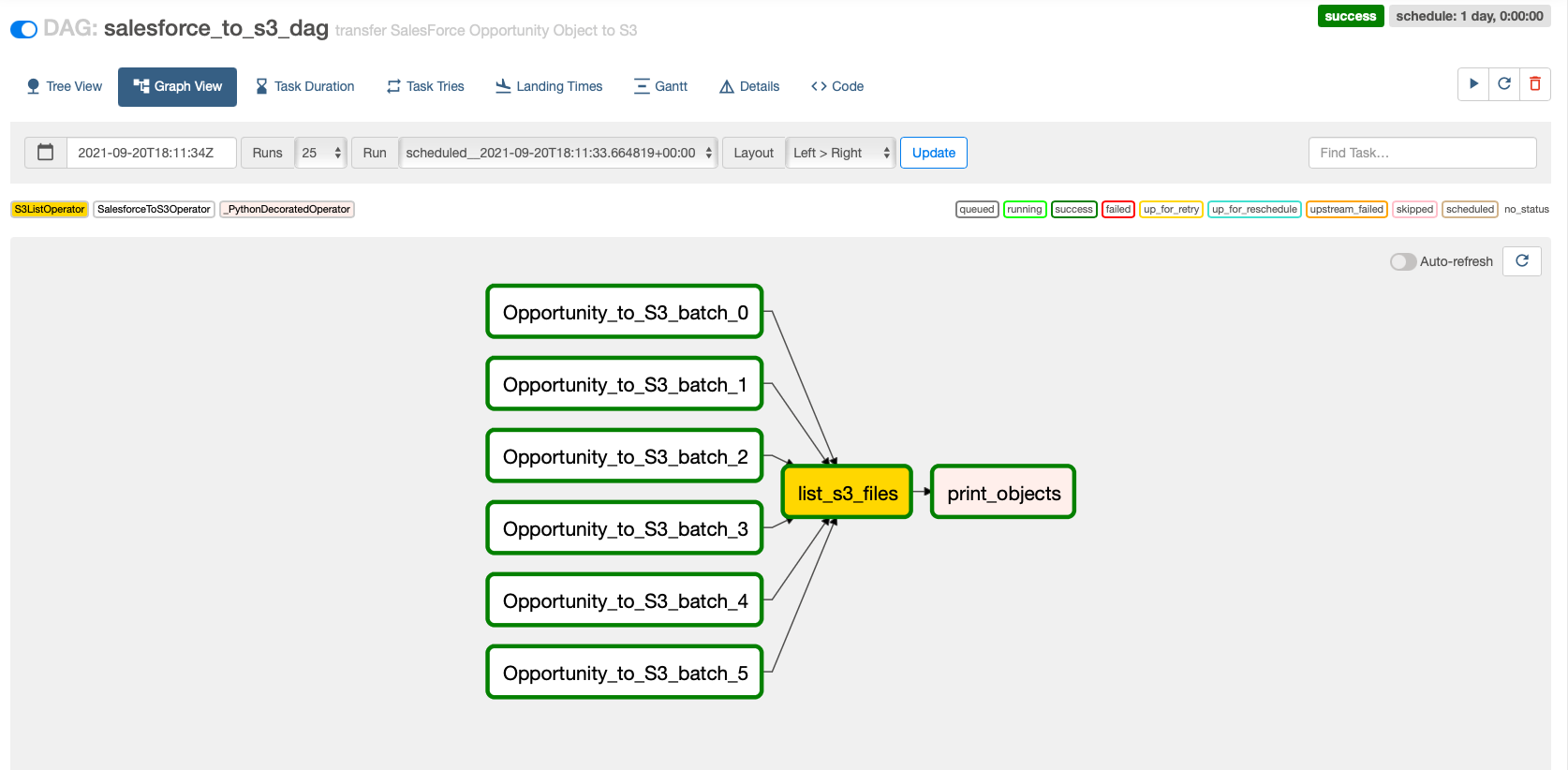
  • How to orchestrate an AWS Glue job from an Airflow Directed Acyclic Graph (DAG).
  • The Airflow Amazon provider package’s observability enhancements in Amazon MWAA. You can now consolidate run logs of AWS Glue jobs on the Airflow console to simplify troubleshooting data pipelines. The Amazon MWAA console becomes a single reference to monitor and analyze AWS Glue job runs. Previously, support teams needed to access the AWS Management Console and take manual steps for this visibility. This feature is available by default from Amazon MWAA version 2.4.3.

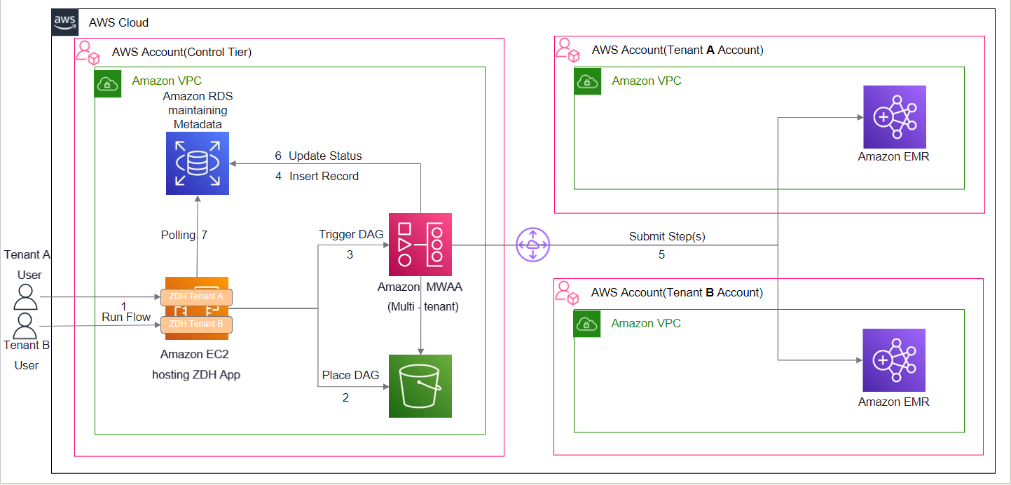
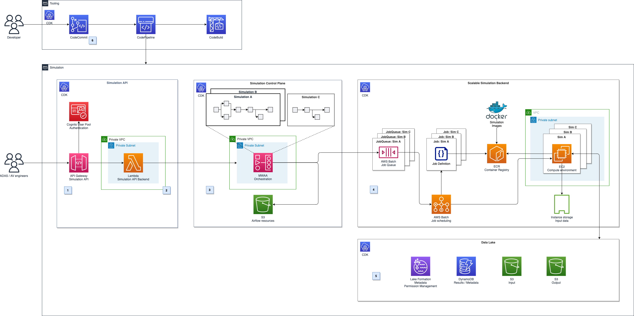
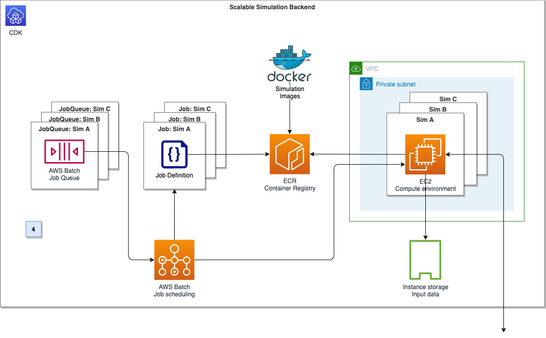
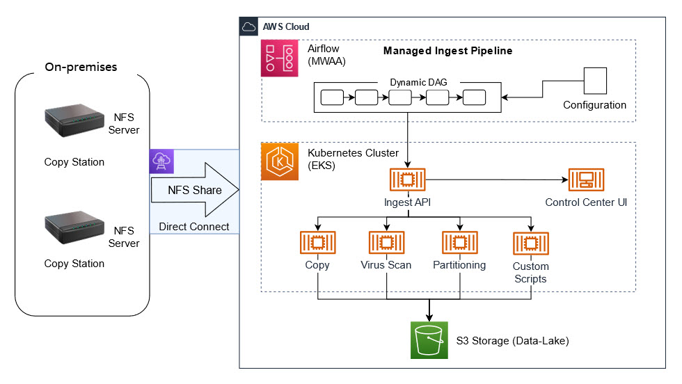
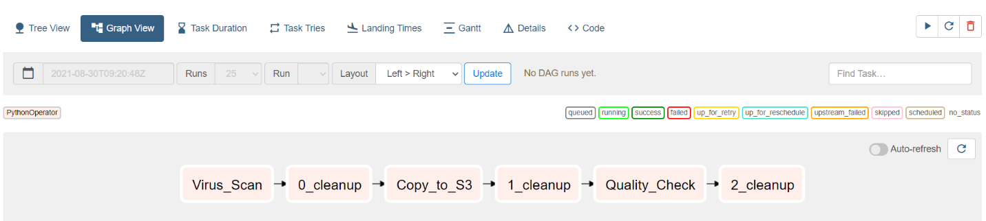
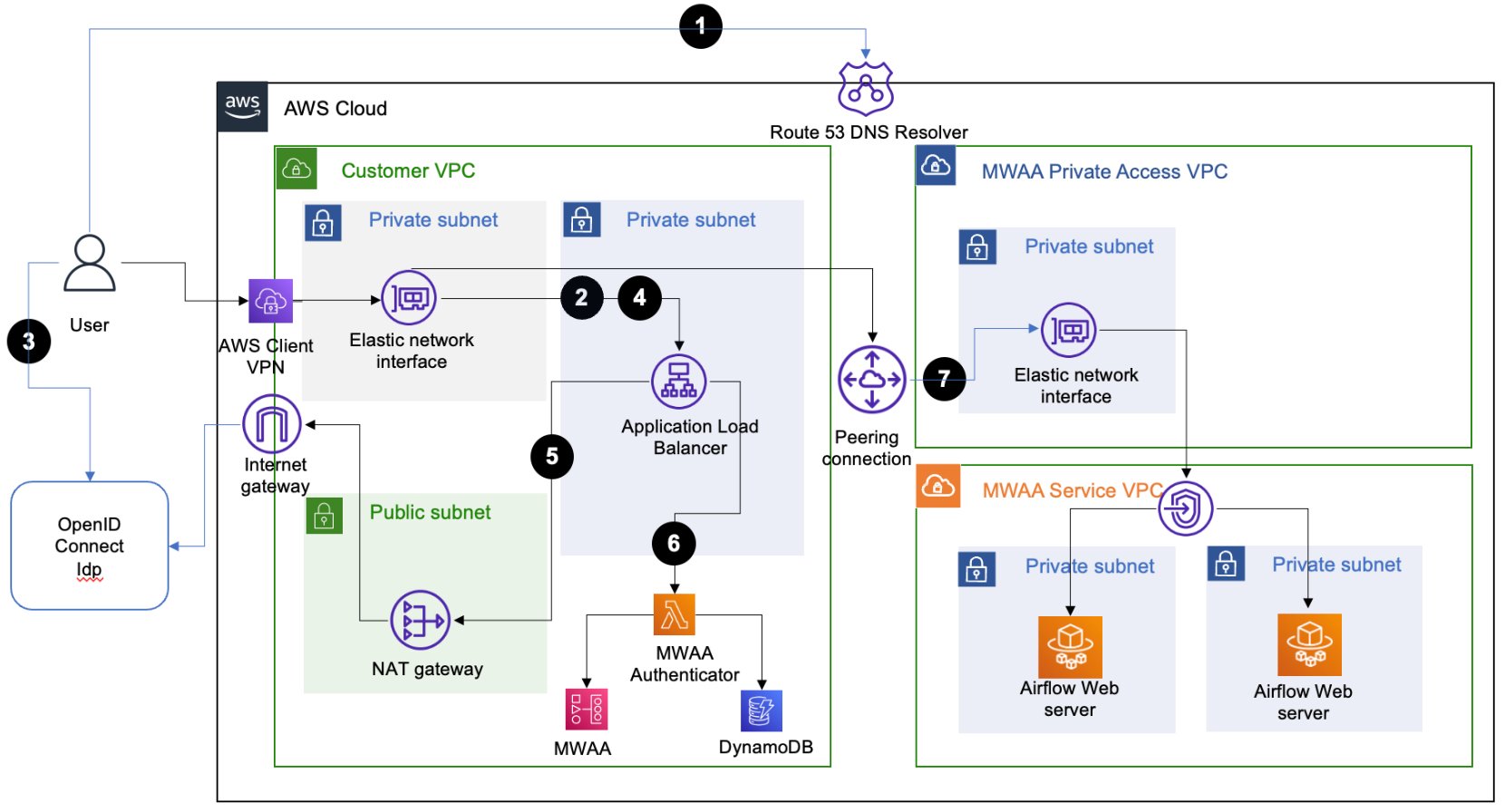
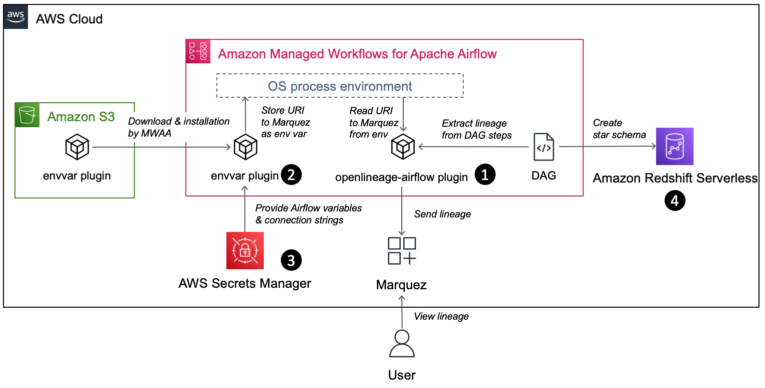
The following diagram illustrates our solution architecture.

Prerequisites

You need the following prerequisites:

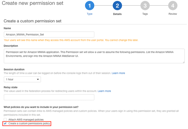
Set up the Amazon MWAA environment

For instructions on creating your environment, refer to Create an Amazon MWAA environment. For existing users, we recommend upgrading to version 2.4.3 to take advantage of the observability enhancements featured in this post.

The steps to upgrade Amazon MWAA to version 2.4.3 differ depending on whether the current version is 1.10.12 or 2.2.2. We discuss both options in this post.

Prerequisites for setting up an Amazon MWAA environment

You must meet the following prerequisites:

Upgrade from version 1.10.12 to 2.4.3

If you’re using Amazon MWAA version 1.10.12, refer to Migrating to a new Amazon MWAA environment to upgrade to 2.4.3.

Upgrade from version 2.0.2 or 2.2.2 to 2.4.3

If you’re using Amazon MWAA environment version 2.2.2 or lower, complete the following steps:

  1. Create a requirements.txt for any custom dependencies with specific versions required for your DAGs.
  2. Upload the file to Amazon S3 in the appropriate location where the Amazon MWAA environment points to the requirements.txt for installing dependencies.
  3. Follow the steps in Migrating to a new Amazon MWAA environment and select version 2.4.3.

Update your DAGs

Customers who upgraded from an older Amazon MWAA environment may need to make updates to existing DAGs. In Airflow version 2.4.3, the Airflow environment will use the Amazon provider package version 6.0.0 by default. This package may include some potentially breaking changes, such as changes to operator names. For example, the AWSGlueJobOperator has been deprecated and replaced with the GlueJobOperator. To maintain compatibility, update your Airflow DAGs by replacing any deprecated or unsupported operators from previous versions with the new ones. Complete the following steps:

  1. Navigate to Amazon AWS Operators.
  2. Select the appropriate version installed in your Amazon MWAA instance (6.0.0. by default) to find a list of supported Airflow operators.
  3. Make the necessary changes in the existing DAG code and upload the modified files to the DAG location in Amazon S3.

Orchestrate the AWS Glue job from Airflow

This section covers the details of orchestrating an AWS Glue job within Airflow DAGs. Airflow eases the development of data pipelines with dependencies between heterogeneous systems such as on-premises processes, external dependencies, other AWS services, and more.

Orchestrate CloudTrail log aggregation with AWS Glue and Amazon MWAA

In this example, we go through a use case of using Amazon MWAA to orchestrate an AWS Glue Python Shell job that persists aggregated metrics based on CloudTrail logs.

CloudTrail enables visibility into AWS API calls that are being made in your AWS account. A common use case with this data would be to gather usage metrics on principals acting on your account’s resources for auditing and regulatory needs.

As CloudTrail events are being logged, they are delivered as JSON files in Amazon S3, which aren’t ideal for analytical queries. We want to aggregate this data and persist it as Parquet files to allow for optimal query performance. As an initial step, we can use Athena to do the initial querying of the data before doing additional aggregations in our AWS Glue job. For more information about creating an AWS Glue Data Catalog table, refer to Creating the table for CloudTrail logs in Athena using partition projection data. After we’ve explored the data via Athena and decided what metrics we want to retain in aggregate tables, we can create an AWS Glue job.

Create an CloudTrail table in Athena

First, we need to create a table in our Data Catalog that allows CloudTrail data to be queried via Athena. The following sample query creates a table with two partitions on the Region and date (called snapshot_date). Be sure to replace the placeholders for your CloudTrail bucket, AWS account ID, and CloudTrail table name:

create external table if not exists `<<<CLOUDTRAIL_TABLE_NAME>>>`(
  `eventversion` string comment 'from deserializer', 
  `useridentity` struct<type:string,principalid:string,arn:string,accountid:string,invokedby:string,accesskeyid:string,username:string,sessioncontext:struct<attributes:struct<mfaauthenticated:string,creationdate:string>,sessionissuer:struct<type:string,principalid:string,arn:string,accountid:string,username:string>>> comment 'from deserializer', 
  `eventtime` string comment 'from deserializer', 
  `eventsource` string comment 'from deserializer', 
  `eventname` string comment 'from deserializer', 
  `awsregion` string comment 'from deserializer', 
  `sourceipaddress` string comment 'from deserializer', 
  `useragent` string comment 'from deserializer', 
  `errorcode` string comment 'from deserializer', 
  `errormessage` string comment 'from deserializer', 
  `requestparameters` string comment 'from deserializer', 
  `responseelements` string comment 'from deserializer', 
  `additionaleventdata` string comment 'from deserializer', 
  `requestid` string comment 'from deserializer', 
  `eventid` string comment 'from deserializer', 
  `resources` array<struct<arn:string,accountid:string,type:string>> comment 'from deserializer', 
  `eventtype` string comment 'from deserializer', 
  `apiversion` string comment 'from deserializer', 
  `readonly` string comment 'from deserializer', 
  `recipientaccountid` string comment 'from deserializer', 
  `serviceeventdetails` string comment 'from deserializer', 
  `sharedeventid` string comment 'from deserializer', 
  `vpcendpointid` string comment 'from deserializer')
PARTITIONED BY ( 
  `region` string,
  `snapshot_date` string)
ROW FORMAT SERDE 
  'com.amazon.emr.hive.serde.CloudTrailSerde' 
STORED AS INPUTFORMAT 
  'com.amazon.emr.cloudtrail.CloudTrailInputFormat' 
OUTPUTFORMAT 
  'org.apache.hadoop.hive.ql.io.HiveIgnoreKeyTextOutputFormat'
LOCATION
  's3://<<<CLOUDTRAIL_BUCKET>>>/AWSLogs/<<<ACCOUNT_ID>>>/CloudTrail/'
TBLPROPERTIES (
  'projection.enabled'='true', 
  'projection.region.type'='enum',
  'projection.region.values'='us-east-2,us-east-1,us-west-1,us-west-2,af-south-1,ap-east-1,ap-south-1,ap-northeast-3,ap-northeast-2,ap-southeast-1,ap-southeast-2,ap-northeast-1,ca-central-1,eu-central-1,eu-west-1,eu-west-2,eu-south-1,eu-west-3,eu-north-1,me-south-1,sa-east-1',
  'projection.snapshot_date.format'='yyyy/mm/dd', 
  'projection.snapshot_date.interval'='1', 
  'projection.snapshot_date.interval.unit'='days', 
  'projection.snapshot_date.range'='2020/10/01,now', 
  'projection.snapshot_date.type'='date',
  'storage.location.template'='s3://<<<CLOUDTRAIL_BUCKET>>>/AWSLogs/<<<ACCOUNT_ID>>>/CloudTrail/${region}/${snapshot_date}')

Run the preceding query on the Athena console, and note the table name and AWS Glue Data Catalog database where it was created. We use these values later in the Airflow DAG code.

Sample AWS Glue job code

The following code is a sample AWS Glue Python Shell job that does the following:

  • Takes arguments (which we pass from our Amazon MWAA DAG) on what day’s data to process
  • Uses the AWS SDK for Pandas to run an Athena query to do the initial filtering of the CloudTrail JSON data outside AWS Glue
  • Uses Pandas to do simple aggregations on the filtered data
  • Outputs the aggregated data to the AWS Glue Data Catalog in a table
  • Uses logging during processing, which will be visible in Amazon MWAA
import awswrangler as wr
import pandas as pd
import sys
import logging
from awsglue.utils import getResolvedOptions
from datetime import datetime, timedelta

# Logging setup, redirects all logs to stdout
LOGGER = logging.getLogger()
formatter = logging.Formatter('%(asctime)s.%(msecs)03d %(levelname)s %(module)s - %(funcName)s: %(message)s')
streamHandler = logging.StreamHandler(sys.stdout)
streamHandler.setFormatter(formatter)
LOGGER.addHandler(streamHandler)
LOGGER.setLevel(logging.INFO)

LOGGER.info(f"Passed Args :: {sys.argv}")

sql_query_template = """
select
region,
useridentity.arn,
eventsource,
eventname,
useragent

from "{cloudtrail_glue_db}"."{cloudtrail_table}"
where snapshot_date='{process_date}'
and region in ('us-east-1','us-east-2')
"""

required_args = ['CLOUDTRAIL_GLUE_DB',
                'CLOUDTRAIL_TABLE',
                'TARGET_BUCKET',
                'TARGET_DB',
                'TARGET_TABLE',
                'ACCOUNT_ID']
arg_keys = [*required_args, 'PROCESS_DATE'] if '--PROCESS_DATE' in sys.argv else required_args
JOB_ARGS = getResolvedOptions ( sys.argv, arg_keys)

LOGGER.info(f"Parsed Args :: {JOB_ARGS}")

# if process date was not passed as an argument, process yesterday's data
process_date = (
    JOB_ARGS['PROCESS_DATE']
    if JOB_ARGS.get('PROCESS_DATE','NONE') != "NONE" 
    else (datetime.today() - timedelta(days=1)).strftime("%Y-%m-%d") 
)

LOGGER.info(f"Taking snapshot for :: {process_date}")

RAW_CLOUDTRAIL_DB = JOB_ARGS['CLOUDTRAIL_GLUE_DB']
RAW_CLOUDTRAIL_TABLE = JOB_ARGS['CLOUDTRAIL_TABLE']
TARGET_BUCKET = JOB_ARGS['TARGET_BUCKET']
TARGET_DB = JOB_ARGS['TARGET_DB']
TARGET_TABLE = JOB_ARGS['TARGET_TABLE']
ACCOUNT_ID = JOB_ARGS['ACCOUNT_ID']

final_query = sql_query_template.format(
    process_date=process_date.replace("-","/"),
    cloudtrail_glue_db=RAW_CLOUDTRAIL_DB,
    cloudtrail_table=RAW_CLOUDTRAIL_TABLE
)

LOGGER.info(f"Running Query :: {final_query}")

raw_cloudtrail_df = wr.athena.read_sql_query(
    sql=final_query,
    database=RAW_CLOUDTRAIL_DB,
    ctas_approach=False,
    s3_output=f"s3://{TARGET_BUCKET}/athena-results",
)

raw_cloudtrail_df['ct']=1

agg_df = raw_cloudtrail_df.groupby(['arn','region','eventsource','eventname','useragent'],as_index=False).agg({'ct':'sum'})
agg_df['snapshot_date']=process_date

LOGGER.info(agg_df.info(verbose=True))

upload_path = f"s3://{TARGET_BUCKET}/{TARGET_DB}/{TARGET_TABLE}"

if not agg_df.empty:
    LOGGER.info(f"Upload to {upload_path}")
    try:
        response = wr.s3.to_parquet(
            df=agg_df,
            path=upload_path,
            dataset=True,
            database=TARGET_DB,
            table=TARGET_TABLE,
            mode="overwrite_partitions",
            schema_evolution=True,
            partition_cols=["snapshot_date"],
            compression="snappy",
            index=False
        )
        LOGGER.info(response)
    except Exception as exc:
        LOGGER.error("Uploading to S3 failed")
        LOGGER.exception(exc)
        raise exc
else:
    LOGGER.info(f"Dataframe was empty, nothing to upload to {upload_path}")

The following are some key advantages in this AWS Glue job:

  • We use an Athena query to ensure initial filtering is done outside of our AWS Glue job. As such, a Python Shell job with minimal compute is still sufficient for aggregating a large CloudTrail dataset.
  • We ensure the analytics library-set option is turned on when creating our AWS Glue job to use the AWS SDK for Pandas library.

Create an AWS Glue job

Complete the following steps to create your AWS Glue job:

  1. Copy the script in the preceding section and save it in a local file. For this post, the file is called script.py.
  2. On the AWS Glue console, choose ETL jobs in the navigation pane.
  3. Create a new job and select Python Shell script editor.
  4. Select Upload and edit an existing script and upload the file you saved locally.
  5. Choose Create.

  1. On the Job details tab, enter a name for your AWS Glue job.
  2. For IAM role, choose an existing role or create a new role that has the required permissions for Amazon S3, AWS Glue, and Athena. The role needs to query the CloudTrail table you created earlier and write to an output location.

You can use the following sample policy code. Replace the placeholders with your CloudTrail logs bucket, output table name, output AWS Glue database, output S3 bucket, CloudTrail table name, AWS Glue database containing the CloudTrail table, and your AWS account ID.

{
    "Version": "2012-10-17",
    "Statement": [
        {
            "Action": [
                "s3:List*",
                "s3:Get*"
            ],
            "Resource": [
                "arn:aws:s3:::<<<CLOUDTRAIL_LOGS_BUCKET>>>/*",
                "arn:aws:s3:::<<<CLOUDTRAIL_LOGS_BUCKET>>>*"
            ],
            "Effect": "Allow",
            "Sid": "GetS3CloudtrailData"
        },
        {
            "Action": [
                "glue:Get*",
                "glue:BatchGet*"
            ],
            "Resource": [
                "arn:aws:glue:us-east-1:<<<YOUR_AWS_ACCT_ID>>>:catalog",
                "arn:aws:glue:us-east-1:<<<YOUR_AWS_ACCT_ID>>>:database/<<<GLUE_DB_WITH_CLOUDTRAIL_TABLE>>>",
                "arn:aws:glue:us-east-1:<<<YOUR_AWS_ACCT_ID>>>:table/<<<GLUE_DB_WITH_CLOUDTRAIL_TABLE>>>/<<<CLOUDTRAIL_TABLE>>>*"
            ],
            "Effect": "Allow",
            "Sid": "GetGlueCatalogCloudtrailData"
        },
        {
            "Action": [
                "s3:PutObject*",
                "s3:Abort*",
                "s3:DeleteObject*",
                "s3:GetObject*",
                "s3:GetBucket*",
                "s3:List*",
                "s3:Head*"
            ],
            "Resource": [
                "arn:aws:s3:::<<<OUTPUT_S3_BUCKET>>>",
                "arn:aws:s3:::<<<OUTPUT_S3_BUCKET>>>/<<<OUTPUT_GLUE_DB>>>/<<<OUTPUT_TABLE_NAME>>>/*"
            ],
            "Effect": "Allow",
            "Sid": "WriteOutputToS3"
        },
        {
            "Action": [
                "glue:CreateTable",
                "glue:CreatePartition",
                "glue:UpdatePartition",
                "glue:UpdateTable",
                "glue:DeleteTable",
                "glue:DeletePartition",
                "glue:BatchCreatePartition",
                "glue:BatchDeletePartition",
                "glue:Get*",
                "glue:BatchGet*"
            ],
            "Resource": [
                "arn:aws:glue:us-east-1:<<<YOUR_AWS_ACCT_ID>>>:catalog",
                "arn:aws:glue:us-east-1:<<<YOUR_AWS_ACCT_ID>>>:database/<<<OUTPUT_GLUE_DB>>>",
                "arn:aws:glue:us-east-1:<<<YOUR_AWS_ACCT_ID>>>:table/<<<OUTPUT_GLUE_DB>>>/<<<OUTPUT_TABLE_NAME>>>*"
            ],
            "Effect": "Allow",
            "Sid": "AllowOutputToGlue"
        },
        {
            "Action": [
                "logs:CreateLogGroup",
                "logs:CreateLogStream",
                "logs:PutLogEvents"
            ],
            "Resource": "arn:aws:logs:*:*:/aws-glue/*",
            "Effect": "Allow",
            "Sid": "LogsAccess"
        },
        {
            "Action": [
                "s3:GetObject*",
                "s3:GetBucket*",
                "s3:List*",
                "s3:DeleteObject*",
                "s3:PutObject",
                "s3:PutObjectLegalHold",
                "s3:PutObjectRetention",
                "s3:PutObjectTagging",
                "s3:PutObjectVersionTagging",
                "s3:Abort*"
            ],
            "Resource": [
                "arn:aws:s3:::<<<ATHENA_RESULTS_BUCKET>>>",
                "arn:aws:s3:::<<<ATHENA_RESULTS_BUCKET>>>/*"
            ],
            "Effect": "Allow",
            "Sid": "AccessToAthenaResults"
        },
        {
            "Action": [
                "athena:StartQueryExecution",
                "athena:StopQueryExecution",
                "athena:GetDataCatalog",
                "athena:GetQueryResults",
                "athena:GetQueryExecution"
            ],
            "Resource": [
                "arn:aws:glue:us-east-1:<<<YOUR_AWS_ACCT_ID>>>:catalog",
                "arn:aws:athena:us-east-1:<<<YOUR_AWS_ACCT_ID>>>:datacatalog/AwsDataCatalog",
                "arn:aws:athena:us-east-1:<<<YOUR_AWS_ACCT_ID>>>:workgroup/primary"
            ],
            "Effect": "Allow",
            "Sid": "AllowAthenaQuerying"
        }
    ]
}

For Python version, choose Python 3.9.

  1. Select Load common analytics libraries.
  2. For Data processing units, choose 1 DPU.
  3. Leave the other options as default or adjust as needed.

  1. Choose Save to save your job configuration.

Configure an Amazon MWAA DAG to orchestrate the AWS Glue job

The following code is for a DAG that can orchestrate the AWS Glue job that we created. We take advantage of the following key features in this DAG:

"""Sample DAG"""
import airflow.utils
from airflow.providers.amazon.aws.operators.glue import GlueJobOperator
from airflow import DAG
from datetime import timedelta
import airflow.utils

# allow backfills via DAG run parameters
process_date = '{{ dag_run.conf.get("process_date") if dag_run.conf.get("process_date") else "NONE" }}'

dag = DAG(
    dag_id = "CLOUDTRAIL_LOGS_PROCESSING",
    default_args = {
        'depends_on_past':False, 
        'start_date':airflow.utils.dates.days_ago(0),
        'retries':1,
        'retry_delay':timedelta(minutes=5),
        'catchup': False
    },
    schedule_interval = None, # None for unscheduled or a cron expression - E.G. "00 12 * * 2" - at 12noon Tuesday
    dagrun_timeout = timedelta(minutes=30),
    max_active_runs = 1,
    max_active_tasks = 1 # since there is only one task in our DAG
)

## Log ingest. Assumes Glue Job is already created
glue_ingestion_job = GlueJobOperator(
    task_id="<<<some-task-id>>>",
    job_name="<<<GLUE_JOB_NAME>>>",
    script_args={
        "--ACCOUNT_ID":"<<<YOUR_AWS_ACCT_ID>>>",
        "--CLOUDTRAIL_GLUE_DB":"<<<GLUE_DB_WITH_CLOUDTRAIL_TABLE>>>",
        "--CLOUDTRAIL_TABLE":"<<<CLOUDTRAIL_TABLE>>>",
        "--TARGET_BUCKET": "<<<OUTPUT_S3_BUCKET>>>",
        "--TARGET_DB": "<<<OUTPUT_GLUE_DB>>>", # should already exist
        "--TARGET_TABLE": "<<<OUTPUT_TABLE_NAME>>>",
        "--PROCESS_DATE": process_date
    },
    region_name="us-east-1",
    dag=dag,
    verbose=True
)

glue_ingestion_job

Increase observability of AWS Glue jobs in Amazon MWAA

The AWS Glue jobs write logs to Amazon CloudWatch. With the recent observability enhancements to Airflow’s Amazon provider package, these logs are now integrated with Airflow task logs. This consolidation provides Airflow users with end-to-end visibility directly in the Airflow UI, eliminating the need to search in CloudWatch or the AWS Glue console.

To use this feature, ensure the IAM role attached to the Amazon MWAA environment has the following permissions to retrieve and write the necessary logs:

{
  "Version": "2012-10-17",
  "Statement": [
    {
      "Effect": "Allow",
      "Action": [
        "logs:CreateLogGroup",
        "logs:CreateLogStream",
        "logs:PutLogEvents",
        "logs:GetLogEvents",
        "logs:GetLogRecord",
        "logs:DescribeLogStreams",
        "logs:FilterLogEvents",
        "logs:GetLogGroupFields",
        "logs:GetQueryResults",
        
      ],
      "Resource": [
        "arn:aws:logs:*:*:log-group:airflow-243-<<<Your environment name>>>-*"--Your Amazon MWAA Log Stream Name
      ]
    }
  ]
}

If verbose=true, the AWS Glue job run logs show in the Airflow task logs. The default is false. For more information, refer to Parameters.

When enabled, the DAGs read from the AWS Glue job’s CloudWatch log stream and relay them to the Airflow DAG AWS Glue job step logs. This provides detailed insights into an AWS Glue job’s run in real time via the DAG logs. Note that AWS Glue jobs generate an output and error CloudWatch log group based on the job’s STDOUT and STDERR, respectively. All logs in the output log group and exception or error logs from the error log group are relayed into Amazon MWAA.

AWS admins can now limit a support team’s access to only Airflow, making Amazon MWAA the single pane of glass on job orchestration and job health management. Previously, users needed to check AWS Glue job run status in the Airflow DAG steps and retrieve the job run identifier. They then needed to access the AWS Glue console to find the job run history, search for the job of interest using the identifier, and finally navigate to the job’s CloudWatch logs to troubleshoot.

Create the DAG

To create the DAG, complete the following steps:

  1. Save the preceding DAG code to a local .py file, replacing the indicated placeholders.

The values for your AWS account ID, AWS Glue job name, AWS Glue database with CloudTrail table, and CloudTrail table name should already be known. You can adjust the output S3 bucket, output AWS Glue database, and output table name as needed, but make sure the AWS Glue job’s IAM role that you used earlier is configured accordingly.

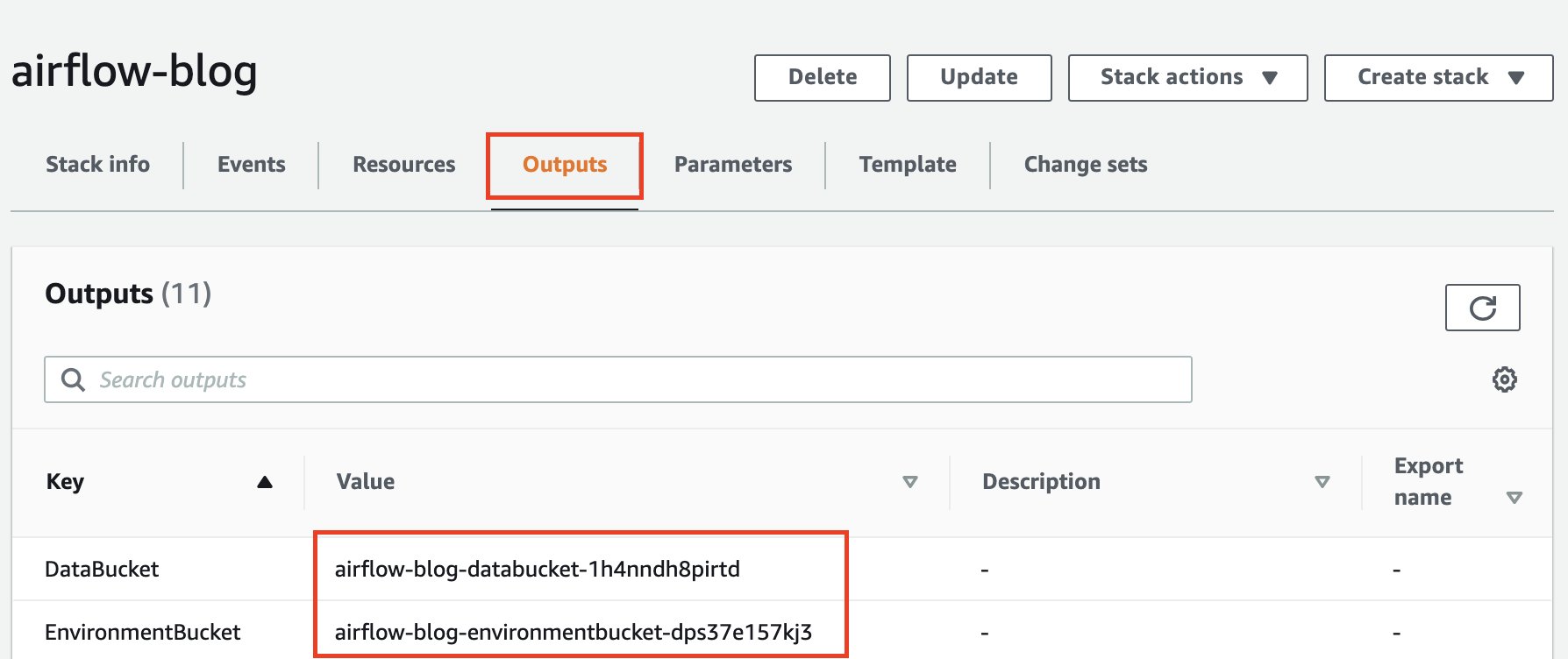
  1. On the Amazon MWAA console, navigate to your environment to see where the DAG code is stored.

The DAGs folder is the prefix within the S3 bucket where your DAG file should be placed.

  1. Upload your edited file there.

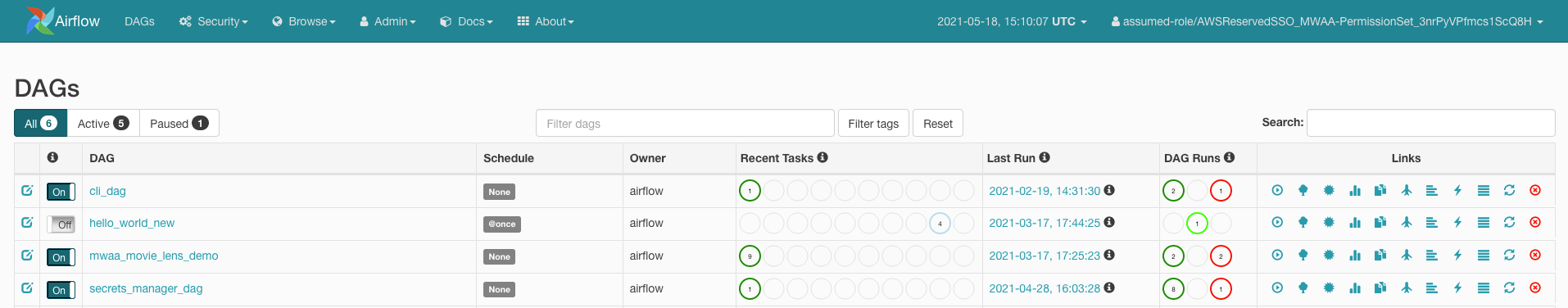
  1. Open the Amazon MWAA console to confirm that the DAG appears in the table.

Run the DAG

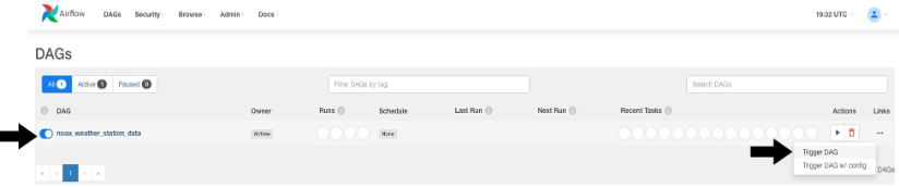
To run the DAG, complete the following steps:

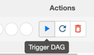
  1. Choose from the following options:
    • Trigger DAG – This causes yesterday’s data to be used as the data to process
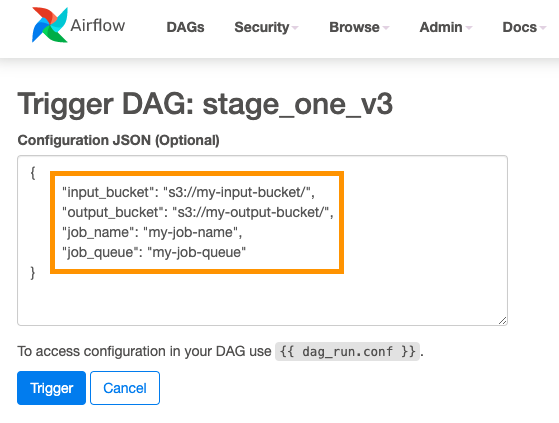
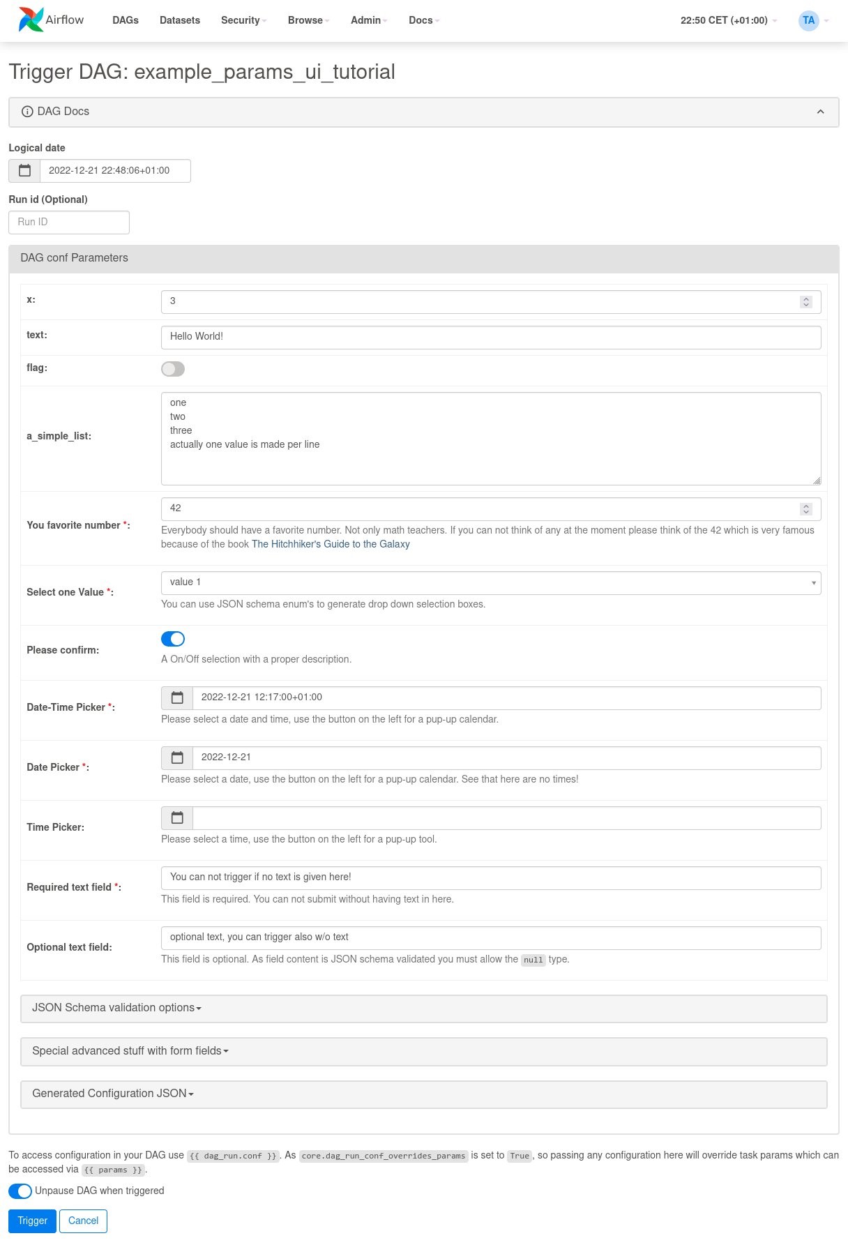
    • Trigger DAG w/ config – With this option, you can pass in a different date, potentially for backfills, which is retrieved using dag_run.conf in the DAG code and then passed into the AWS Glue job as a parameter

The following screenshot shows the additional configuration options if you choose Trigger DAG w/ config.

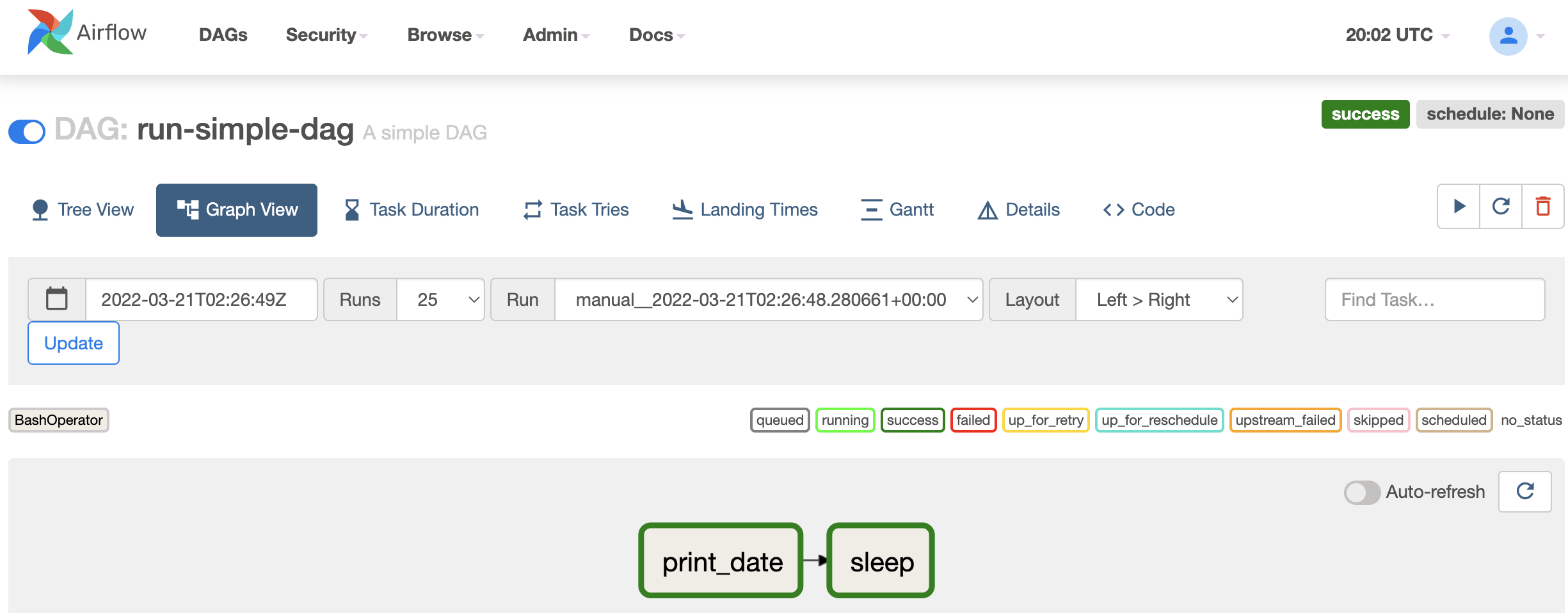
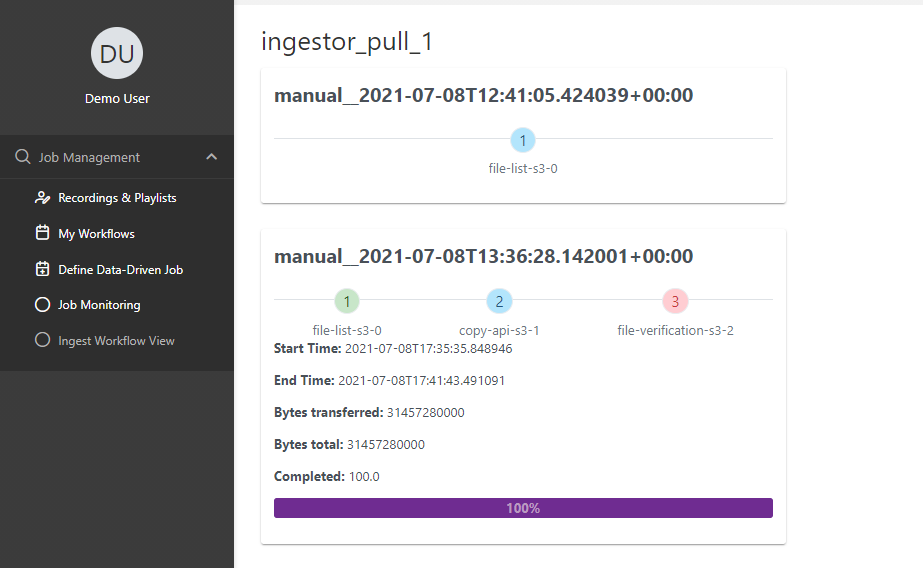
  1. Monitor the DAG as it runs.
  2. When the DAG is complete, open the run’s details.

On the right pane, you can view the logs, or choose Task Instance Details for a full view.

  1. View the AWS Glue job output logs in Amazon MWAA without using the AWS Glue console thanks to the GlueJobOperator verbose flag.

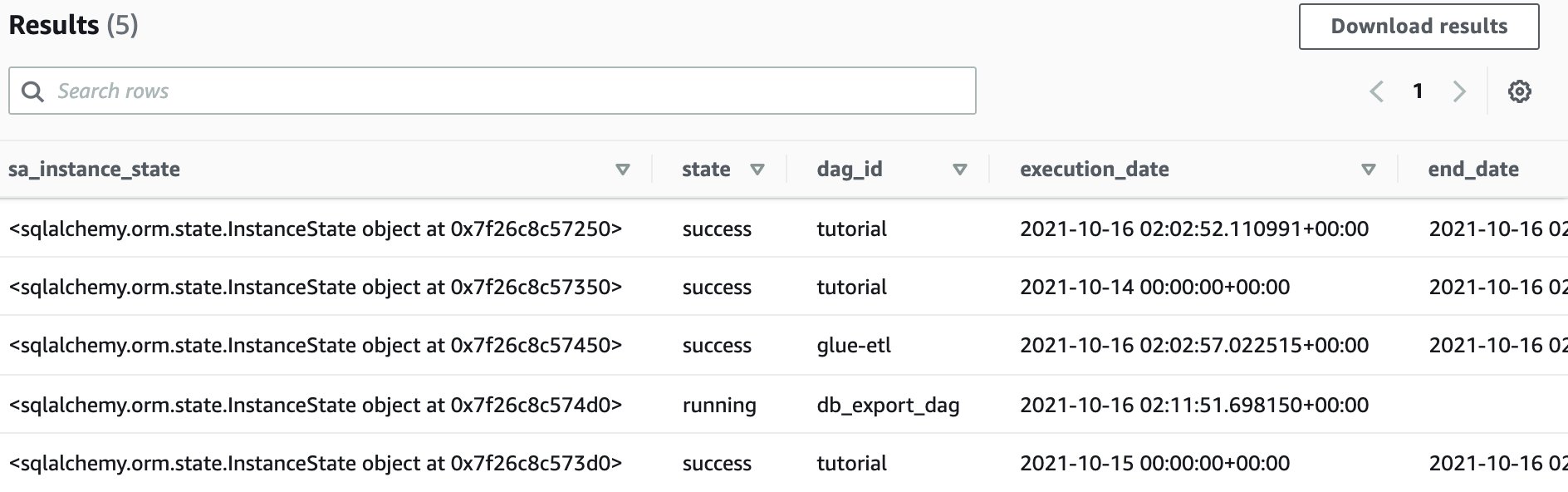
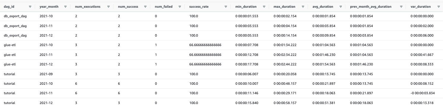
The AWS Glue job will have written results to the output table you specified.

  1. Query this table via Athena to confirm it was successful.

Summary

Amazon MWAA now provides a single place to track AWS Glue job status and enables you to use the Airflow console as the single pane of glass for job orchestration and health management. In this post, we walked through the steps to orchestrate AWS Glue jobs via Airflow using GlueJobOperator. With the new observability enhancements, you can seamlessly troubleshoot AWS Glue jobs in a unified experience. We also demonstrated how to upgrade your Amazon MWAA environment to a compatible version, update dependencies, and change the IAM role policy accordingly.

For more information about common troubleshooting steps, refer to Troubleshooting: Creating and updating an Amazon MWAA environment. For in-depth details of migrating to an Amazon MWAA environment, refer to Upgrading from 1.10 to 2. To learn about the open-source code changes for increased observability of AWS Glue jobs in the Airflow Amazon provider package, refer to the relay logs from AWS Glue jobs.

Finally, we recommend visiting the AWS Big Data Blog for other material on analytics, ML, and data governance on AWS.


About the Authors

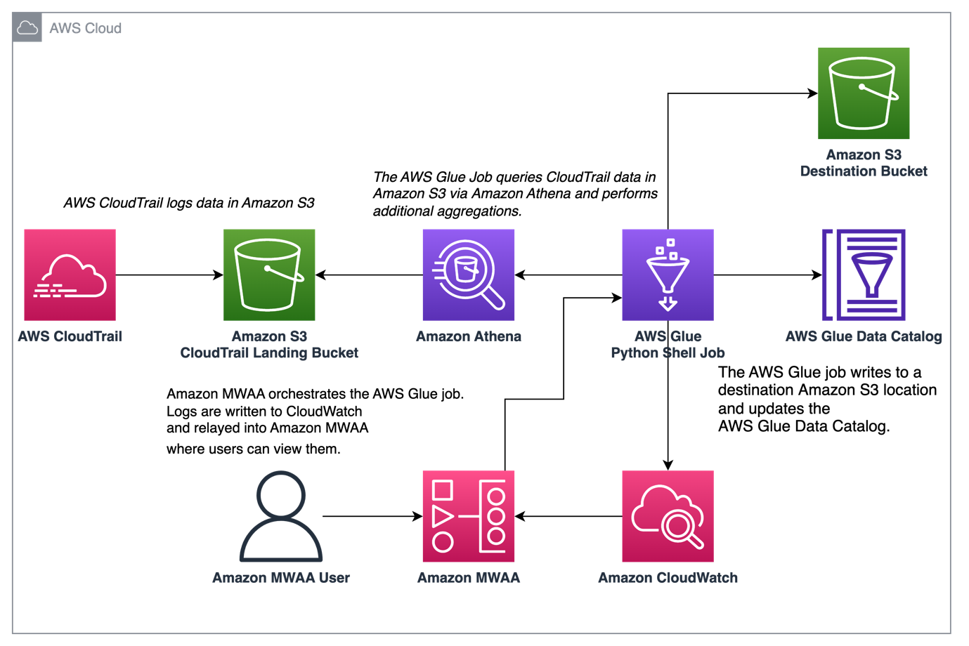
Rushabh Lokhande is a Data & ML Engineer with the AWS Professional Services Analytics Practice. He helps customers implement big data, machine learning, and analytics solutions. Outside of work, he enjoys spending time with family, reading, running, and golf.

Ryan Gomes is a Data & ML Engineer with the AWS Professional Services Analytics Practice. He is passionate about helping customers achieve better outcomes through analytics and machine learning solutions in the cloud. Outside of work, he enjoys fitness, cooking, and spending quality time with friends and family.

Vishwa Gupta is a Senior Data Architect with the AWS Professional Services Analytics Practice. He helps customers implement big data and analytics solutions. Outside of work, he enjoys spending time with family, traveling, and trying new food.

What’s new with Amazon MWAA support for startup scripts

Post Syndicated from Parnab Basak original https://aws.amazon.com/blogs/big-data/whats-new-with-amazon-mwaa-support-for-startup-scripts/

Amazon Managed Workflow for Apache Airflow (Amazon MWAA) is a managed service for Apache Airflow that lets you use the same familiar Apache Airflow environment to orchestrate your workflows and enjoy improved scalability, availability, and security without the operational burden of having to manage the underlying infrastructure.

In April 2023, Amazon MWAA added support for shell launch scripts for environment versions Apache Airflow 2.x and later. With this feature, you can customize the Apache Airflow environment by launching a custom shell launch script at startup to work better with existing integration infrastructure and help with your compliance needs. You can use this shell launch script to install custom Linux runtimes, set environment variables, and update configuration files. Amazon MWAA runs this script during startup on every individual Apache Airflow component (worker, scheduler, and web server) before installing requirements and initializing the Apache Airflow process.

In this post, we provide an overview of the features, explore applicable use cases, detail the steps to use it, and provide additional facts on the capabilities of this shell launch script.

Solution overview

To run Apache Airflow, Amazon MWAA builds Amazon Elastic Container Registry (Amazon ECR) images that bundle Apache Airflow releases with other common binaries and Python libraries. These images then get used by the AWS Fargate containers in the Amazon MWAA environment. You can bring in additional libraries through the requirements.txt and plugins.zip files and pass the Amazon Simple Storage Service (Amazon S3) paths as a parameter during environment creation or update.

However, this method to install packages didn’t cover all of your use cases to tailor your Apache Airflow environments. Customers asked us for a way to customize the Apache Airflow container images by specifying custom libraries, runtimes, and supported files.

Applicable use cases

The new feature adds the ability to customize your Apache Airflow image by launching a custom specified shell launch script at startup. You can use the shell launch script to perform actions such as the following:

  • Install runtimes – Install or update Linux runtimes required by your workflows and connections. For example, you can install libaio as a custom library for Oracle.
  • Configure environment variables – Set environment variables for the Apache Airflow scheduler, web server, and worker components. You can overwrite common variables such as PATH, PYTHONPATH, and LD_LIBRARY_PATH. For example, you can set LD_LIBRARY_PATH to instruct Python to look for binaries in the paths that you specify.
  • Manage keys and tokens – Pass access tokens for your private PyPI/PEP-503 compliant custom repositories to requirements.txt and configure security keys.

How it works

The shell script runs Bash commands at startup, so you can install using yum and other tools similar to how Amazon Elastic Cloud Compute Cloud (Amazon EC2) offers user data and shell scripts support. You can define a custom shell script with the .sh extension and place it in the same S3 bucket as requirements.txt and plugins.zip. You can define an S3 file version of the shell script during the environment creation or update via the Amazon MWAA console, API, or AWS Command Line Interface (AWS CLI). For details on how to configure the startup script, refer to Using a startup script with Amazon MWAA.

During the environment creation or update process, Amazon MWAA copies the plugins.zip, requirements.txt, shell script, and your Apache Airflow Directed Acrylic Graphs (DAGs) to the container images on the underlying Amazon Elastic Container Service (Amazon ECS) Fargate clusters. The Amazon MWAA instance extracts these contents and runs the startup script file that you specified. The startup script is run from the /usr/local/airflow/startup Apache Airflow directory as the airflow user. When it’s complete, the setup process will install the requirements.txt and plugins.zip files, followed by the Apache Airflow process associated with the container.

The following screenshot shows you the new optional Startup script file field on the Amazon MWAA console.

For monitoring and observability, you can view the output of the script in your Amazon MWAA environment’s Amazon CloudWatch log groups. To view the logs, you need to enable logging for the log group. If enabled, Amazon MWAA creates a new log stream starting with the prefix startup_script_exection_ip. You can retrieve log events to verify that the script is working as expected.

You can also use Amazon MWAA local-runner to test this feature on your local development environments. You can now specify your custom startup script in the startup_script directory in the local-runner. It’s recommended that you locally test your script before applying changes to your Amazon MWAA setup.

You can reference files that you package within plugins.zip or your DAGs folder from your startup script. This can be beneficial if you require installing Linux runtimes on a private web server from a local package. It’s also useful to be able to skip installation of Python libraries on a web server that doesn’t have access, either due to private web server mode or for libraries hosted on a private repository accessible only from your VPC, such as in the following example:

#!/bin/sh
export ENVIRONMENT_STAGE=”development”
echo “$ENVIRONMENT_STAGE”

if [“${MWAA_AIRFLOW_COMPONENT} != “webserver”
then
pip3 install -r /usr/local/airflow/dags/requirements.txt
fi

The MWAA_AIRFLOW_COMPONENT variable used in the script identifies each Apache Airflow scheduler, web server, and worker component that the script runs on.

Additional considerations

Keep in mind the following additional information of this feature:

  • Specifying a startup shell script file is optional. You can pick a specific S3 file version of your script.
  • Updating the startup script to an existing Amazon MWAA environment will lead to a restart of the environment. Amazon MWAA runs the startup script as each component in your environment restarts. Environment updates can take 10–30 minutes. We suggest using the Amazon MWAA local-runner to test and reduce the feedback loop.
  • You can make several changes to the Apache Airflow environment, such as setting non-reserved AIRFLOW__ environment variables and installing custom Python libraries. For a detailed list of reserved and unreserved environment variables that you can set or update, refer to Set environment variables using a startup script.
  • Upgrading Apache Airflow core libraries and dependencies or Python versions is not supported. This is because there are constraints used for the base Apache Airflow configuration in Amazon MWAA that will lead to version incompatibility with different installs of the Python runtime and dependent library versions. Amazon MWAA runs validations prior to your custom startup script run to prevent Python or Apache Airflow installs from including triggering workflows.
  • A failure during the startup script run results in an unsuccessful task stabilization of the underlying Amazon ECS Fargate containers. This can impact your Amazon MWAA environment’s ability to successfully create or update.
  • The startup script runtime is limited to 5 minutes, after which it will automatically time out.
  • To revert a startup script that is failing or is no longer required, edit your Amazon MWAA environment to reference a blank .sh file.

Conclusion

In this post, we talked about the new feature of Amazon MWAA that allows you to configure a startup shell launch script. This feature is supported on new and existing Amazon MWAA environments running Apache Airflow 2.x and above. Use this feature to install Linux runtimes, configure environment variables, and manage keys and tokens. You now have an additional option to customize your base Apache Airflow image to meet your specific needs.

For additional details and code examples on Amazon MWAA, visit the Amazon MWAA User Guide and the Amazon MWAA examples GitHub repo.


About the Authors

Parnab Basak is a Solutions Architect and a Serverless Specialist at AWS. He specializes in creating new solutions that are cloud native using modern software development practices like serverless, DevOps, and analytics. Parnab works closely in the analytics and integration services space helping customers adopt AWS services for their workflow orchestration needs.

Vishal Vijayvargiya is a Software Engineer working on Amazon MWAA at Amazon Web Services. He is passionate about building distributed and scalable software systems. Vishal also enjoys playing badminton and cricket.

Automating stopping and starting Amazon MWAA environments to reduce cost

Post Syndicated from James Beswick original https://aws.amazon.com/blogs/compute/automating-stopping-and-starting-amazon-mwaa-environments-to-reduce-cost/

This was written by Uma Ramadoss, Specialist Integration Services, and Chandan Rupakheti, Solutions Architect.

This blog post shows how you can save cost by automating the stopping and starting of an Amazon Managed Workflows for Apache Airflow (Amazon MWAA) environment. It describes how you can retain the data stored in a metadata database and presents an automated solution you can use in your AWS account.

Customers run end to end data pipelines at scale with MWAA. It is a common best practice to run non-production environments for development and testing. A nonproduction environment often does not need to run throughout the day due to factors such as working hours of the development team. As there is no automatic way to stop an MWAA environment when not in use and deleting an environment causes metadata loss, customers often run it continually and pay the full cost.

Overview

Amazon MWAA has a distributed architecture with multiple components such as scheduler, worker, webserver, queue, and database. Customers build data pipelines as Directed Acyclic Graphs (DAGs) and run in Amazon MWAA. The DAGs use variables and connections from the Amazon MWAA metadata database. The history of DAG runs and related data are stored in the same metadata database. The database also stores other information such as user roles and permissions.

When you delete the Amazon MWAA environment, all the components including the database are deleted so that you do not incur any cost. As this normal deletion results in loss of metadata, you need a customized solution to back up the data and to automate the deletion and recreation.

The sample application deletes and recreates your MWAA environment at a scheduled interval defined by you using Amazon EventBridge Scheduler. It exports all metadata into an Amazon S3 bucket before deletion and imports the metadata back to the environment after creation. As this is a managed database and you cannot access the database outside the Amazon MWAA environment, it uses DAGs to import and export the data. The entire process is orchestrated using AWS Step Functions.

Deployment architecture

The sample application is in a GitHub repository. Use the instructions in the readme to deploy the application.

Sample architecture

The sample application deploys the following resources –

  1. A Step Functions state machine to orchestrate the steps needed to delete the MWAA environment.
  2. A Step Functions state machine to orchestrate the steps needed to recreate the MWAA environment.
  3. EventBridge Scheduler rules to trigger the state machines at the scheduled time.
  4. An S3 bucket to store metadata database backup and environment details.
  5. Two DAG files uploaded to the source S3 bucket configured with the MWAA environment. The export DAG exports metadata from the MWAA metadata database to backup S3 bucket. The import DAG restores the metadata from the backup S3 bucket to the newly created MWAA environment.
  6. AWS Lambda functions for triggering the DAGs using MWAA CLI API.
  7. A Step Functions state machine to wait for the long-running MWAA creation and deletion process.
  8. Amazon EventBridge rule to notify on state machine failures.
  9. Amazon Simple Notification Service (Amazon SNS) topic as a target to the EventBridge rule for failure notifications.
  10. Amazon Interface VPC Endpoint for Step Functions for MWAA environment deployed in the private mode.

Stop workflow

At a scheduled time, Amazon EventBridge Scheduler triggers a Step Functions state machine to stop the MWAA environment. The state machine performs the following actions:

Stop workflow

  1. Fetch Amazon MWAA environment details such as airflow configurations, IAM execution role, logging configurations and VPC details.
  2. If the environment is not in the “AVAILABLE” status, it fails the workflow by branching to the “Pausing unsuccessful” state.
  3. Otherwise, it runs the normal workflow and stores the environment details in an S3 bucket so that Start workflow can recreate the environment with this data.
  4. Trigger an MWAA DAG using AWS Lambda function to export metadata to the Amazon S3 bucket. This step uses Step Functions to wait for callback token integration.
  5. Resume the workflow when the task token is returned from the MWAA DAG.
  6. Delete Amazon MWAA environment.
  7. Wait to confirm the deletion.

Start workflow

At a scheduled time, EventBridge Scheduler triggers the Step Functions state machine to recreate the MWAA environment. The steps in the state machine perform the following actions:

Start workflow

  1. Retrieve the environment details stored in Amazon S3 bucket by the stop workflow.
  2. Create an MWAA environment with the same configuration as the original.
  3. Trigger an MWAA DAG through the Lambda function to restore the metadata from the S3 bucket to the newly created environment.

Cost savings

Consider a small MWAA environment in us-east-2 with a minimum of one worker, a maximum of one worker, and 1GB data storage. At the time of this writing, the monthly cost of the environment is $357.80. Let’s assume you use this environment between 6 am and 6 pm on weekdays.

The schedule in the env file of the sample application looks like:

MWAA_PAUSE_CRON_SCHEDULE=’0 18 ? * MON-FRI *’
MWAA_RESUME_CRON_SCHEDULE=’30 5 ? * MON-FRI *’

As MWAA environment creation takes anywhere between 20 and 30 minutes, the MWAA_RESUME_CRON_SCHEDULE is set at 5.30 pm.

Assuming 21 weekdays per month, the monthly cost of the environment is $123.48 and is 65.46% less compared to running the environment continuously:

  • 21 weekdays * 12 hours * 0.49 USD per hour = $123.48

Additional considerations

The sample application only restores at-store data. Though the deletion process pauses all the DAGs before making the backup, it cannot stop any running tasks or in-flight messages in the queue. It also does not backup tasks that are not in completed state. This can result in task history loss for the tasks that were running during the backup.

Over time, the metadata grows in size, which can increase latency in query performance. You can use a DAG as shown in the example to clean up the database regularly.

Avoid setting the catchup by default configuration flag in the environment setting to true or in the DAG definition unless it is required. Catch up feature runs all the DAG runs that are missed for any data interval. When the environment is created again, if the flag is true, it catches up with the missed DAG runs and can overload the environment.

Conclusion

Automating the deletion and recreation of Amazon MWAA environments is a powerful solution for cost optimization and efficient management of resources. By following the steps outlined in this blog post, you can ensure that your MWAA environment is deleted and recreated without losing any of the metadata or configurations. This allows you to deploy new code changes and updates more quickly and easily, without having to configure your environment each time manually.

The potential cost savings of running your MWAA environment for only 12 hours on weekdays are significant. The example shows how you can save up to 65% of your monthly costs by choosing this option. This makes it an attractive solution for organizations that are looking to reduce cost while maintaining a high level of performance.

Visit the samples repository to learn more about Amazon MWAA. It contains a wide variety of examples and templates that you can use to build your own applications.

For more serverless learning resources, visit Serverless Land.

What’s new with Amazon MWAA support for Apache Airflow version 2.4.3

Post Syndicated from Parnab Basak original https://aws.amazon.com/blogs/big-data/whats-new-with-amazon-mwaa-support-for-apache-airflow-version-2-4-3/

Amazon Managed Workflows for Apache Airflow (Amazon MWAA) is a managed orchestration service for Apache Airflow that makes it simple to set up and operate end-to-end data pipelines in the cloud at scale. Amazon MWAA supports multiple versions of Apache Airflow (v1.10.12, v2.0.2, and v2.2.2). Earlier in 2023, we added support for Apache Airflow v2.4.3 so you can enjoy the same scalability, availability, security, and ease of management with Airflow’s most recent improvements. Additionally, with Apache Airflow v2.4.3 support, Amazon MWAA has upgraded to Python v3.10.8, which supports newer Python libraries like OpenSSL 1.1.1 as well as major new features and improvements.

In this post, we provide an overview of the features and capabilities of Apache Airflow v2.4.3 and how you can set up or upgrade your Amazon MWAA environment to accommodate Apache Airflow v2.4.3 as you orchestrate using workflows in the cloud at scale.

New feature: Data-aware scheduling using datasets

With the release of Apache Airflow v2.4.0, Airflow introduced datasets. An Airflow dataset is a stand-in for a logical grouping of data that can trigger a Directed Acyclic Graph (DAG) in addition to regular DAG triggering mechanisms such as cron expressions, timedelta objects, and Airflow timetables. The following are some of the attributes of a dataset:

  • Datasets may be updated by upstream producer tasks, and updates to such datasets contribute to scheduling downstream consumer DAGs.
  • You can create smaller, more self-contained DAGs, which chain together into a larger data-based workflow using datasets.
  • You have an additional option now to create inter-DAG dependencies using datasets besides ExternalTaskSensor or TriggerDagRunOperator. You should consider using this dependency if you have two DAGs related via an irregular dataset update. This type of dependency also provides you with increased observability into the dependencies between your DAGs and datasets in the Airflow UI.

How data-aware scheduling works

You need to define three things:

  • A dataset, or multiple datasets
  • The tasks that will update the dataset
  • The DAG that will be scheduled when one or more datasets are updated

The following diagram illustrates the workflow.

The producer DAG has a task that creates or updates the dataset defined by a Uniform Resource Identifier (URI). Airflow schedules the consumer DAG after the dataset has been updated. A dataset will be marked as updated only if the producer task completes successfully—if the task fails or if it’s skipped, no update occurs, and the consumer DAG will not be scheduled. If your updates to a dataset triggers multiple subsequent DAGs, then you can use the Airflow metric max_active_tasks_per_dag to control the parallelism of the consumer DAG and reduce the chance of overloading the system.

Let’s demonstrate this with a code example.

Prerequisites to build a data-aware scheduled DAG

You must have the following prerequisites:

  • An Amazon Simple Storage Service (Amazon S3) bucket to upload datasets in. This can be a separate prefix in your existing S3 bucket configured for your Amazon MWAA environment, or it can be a completely different S3 bucket that you identify to store your data in.
  • An Amazon MWAA environment configured with Apache Airflow v2.4.3. The Amazon MWAA execution role should have access to read and write to the S3 bucket configured to upload datasets. The latter is only needed if it’s a different bucket than the Amazon MWAA bucket.

The following diagram illustrates the solution architecture.

The workflow steps are as follows:

  1. The producer DAG makes an API call to a publicly hosted API to retrieve data.
  2. After the data has been retrieved, it’s stored in the S3 bucket.
  3. The update to this dataset subsequently triggers the consumer DAG.

You can access the producer and consumer code in the GitHub repo.

Test the feature

To test this feature, run the producer DAG. After it’s complete, verify that a file named test.csv is generated in the specified S3 folder. Verify in the Airflow UI that the consumer DAG has been triggered by updates to the dataset and that it runs to completion.

There are two restrictions on the dataset URI:

  • It must be a valid URI, which means it must be composed of only ASCII characters
  • The URI scheme can’t be an Airflow scheme (this is reserved for future use)

Other notable changes in Apache Airflow v2.4.3:

Apache Airflow v2.4.3 has the following additional changes:

  1. Deprecation of schedule_interval and timetable arguments. Airflow v2.4.0 added a new DAG argument schedule that can accept a cron expression, timedelta object, timetable object, or list of dataset objects.
  2. Removal of experimental Smart Sensors. Smart Sensors were added in v2.0 and were deprecated in favor of deferrable operators in v2.2, and have now been removed. Deferrable operators are not yet supported on Amazon MWAA, but will be offered in a future release.
  3. Implementation of ExternalPythonOperator that can help you run some of your tasks with a different set of Python libraries than other tasks (and other than the main Airflow environment).

For detailed release documentation with sample code, visit the Apache Airflow v2.4.0 Release Notes.

New feature: Dynamic task mapping

Dynamic task mapping was a new feature introduced in Apache Airflow v2.3, which has also been extended in v2.4. Dynamic task mapping lets DAG authors create tasks dynamically based on current data. Previously, DAG authors needed to know how many tasks were needed in advance.

This is similar to defining your tasks in a loop, but instead of having the DAG file fetch the data and do that itself, the scheduler can do this based on the output of a previous task. Right before a mapped task is run, the scheduler will create n copies of the task, one for each input. The following diagram illustrates this workflow.

It’s also possible to have a task operate on the collected output of a mapped task, commonly known as map and reduce. This feature is particularly useful if you want to externally process various files, evaluate multiple machine learning models, or extraneously process a varied amount of data based on a SQL request.

How dynamic task mapping works

Let’s see an example using the reference code available in the Airflow documentation.

The following code results in a DAG with n+1 tasks, with n mapped invocations of count_lines, each called to process line counts, and a total that is the sum of each of the count_lines. Here n represents the number of input files uploaded to the S3 bucket.

With n=4 files uploaded, the resulting DAG would look like the following figure.

Prerequisites to build a dynamic task mapped DAG

You need the following prerequisites:

  • An S3 bucket to upload files in. This can be a separate prefix in your existing S3 bucket configured for your Amazon MWAA environment, or it can be a completely different bucket that you identify to store your data in.
  • An Amazon MWAA environment configured with Apache Airflow v2.4.3. The Amazon MWAA execution role should have access to read to the S3 bucket configured to upload files. The latter is only needed if it’s a different bucket than the Amazon MWAA bucket.

You can access the code in the GitHub repo.

Test the feature

Upload the four sample text files from the local data folder to an S3 bucket data folder. Run the dynamic_task_mapping DAG. When it’s complete, verify from the Airflow logs that the final sum is equal to the sum of the count lines of the individual files.

There are two limits that Airflow allows you to place on a task:

  • The number of mapped task instances that can be created as the result of expansion
  • The number of mapped tasks that can run at once

For detailed documentation with sample code, visit the Apache Airflow v2.3.0 Release Notes.

New feature: Upgraded Python version

With Apache Airflow v2.4.3 support, Amazon MWAA has upgraded to Python v3.10.8, providing support for newer Python libraries, features, and improvements. Python v3.10 has slots for data classes, match statements, clearer and better Union typing, parenthesized context managers, and structural pattern matching. Upgrading to Python v3.10 should also help you align with security standards by mitigating the risk of older versions of Python such as 3.7, which is fast approaching its end of security support.

With structural pattern matching in Python v3.10, you can now use switch-case statements instead of using if-else statements and dictionaries to simplify the code. Prior to Python v3.10, you might have used if statements, isinstance calls, exceptions and membership tests against objects, dictionaries, lists, tuples, and sets to verify that the structure of the data matches one or more patterns. The following code shows what an ad hoc pattern matching engine might have looked like prior to Python v3.10:

def http_error(status):
        if status == 200:
           return 'OK'
        elif status == 400:
            return 'Bad request'
 	    elif status == 401:
      	    return 'Not allowed'
	    elif status == 403:
      	    return 'Not allowed'
 	    elif status == 404:
      	    return 'Not allowed'
 	    else:
	        return 'Something is wrong'

With structural pattern matching in Python v3.10, the code is as follows:

def http_error(status):
    match status:
        case 200:
            return 'OK'
        case 400:
            return 'Bad request'
        case 401 | 403 | 404:
            return 'Not allowed'
        case _:
            return 'Something is wrong'

Python v3.10 also carries forward the performance improvements introduced in Python v3.9 using the vectorcall protocol. vectorcall makes many common function calls faster by minimizing or eliminating temporary objects created for the call. In Python 3.9, several Python built-ins—range, tuple, set, frozenset, list, dict—use vectorcall internally to speed up runs. The second big performance enhancer is more efficient in the parsing of Python source code using the new parser for the CPython runtime.

For a full list of Python v3.10 release highlights, refer to What’s New In Python 3.10.

The code is available in the GitHub repo.

Set up a new Apache Airflow v2.4.3 environment

You can set up a new Apache Airflow v2.4.3 environment in your account and preferred Region using either the AWS Management Console, API, or AWS Command Line Interface (AWS CLI). If you’re adopting infrastructure as code (IaC), you can automate the setup using either AWS CloudFormation, the AWS Cloud Development Kit (AWS CDK), or Terraform.

When you have successfully created an Apache Airflow v2.4.3 environment in Amazon MWAA, the following packages are automatically installed on the scheduler and worker nodes along with other provider packages:

  • apache-airflow-providers-amazon==6.0.0
  • python==3.10.8

For a complete list of provider packages installed, refer to Apache Airflow provider packages installed on Amazon MWAA environments. Note that some imports and operator names have changed in the new provider package in order to standardize the naming convention across the provider package. For a complete list of provider package changes, refer to the package changelog.

Upgrade from Apache Airflow v2.0.2 or v2.2.2 to Apache Airflow v2.4.3

Currently, Amazon MWAA doesn’t support in-place upgrades of existing environments for older Apache Airflow versions. In this section, we show how you can transfer your data from your existing Apache Airflow v2.0.2 or v2.2.2 environment to Apache Airflow v2.4.3:

  1. Create a new Apache Airflow v2.4.3 environment.
  2. Copy your DAGs, custom plugins, and requirements.txt resources from your existing v2.0.2 or v2.2.2 S3 bucket to the new environment’s S3 bucket.
    • If you use requirements.txt in your environment, you need to update the --constraint to v2.4.3 constraints and verify that the current libraries and packages are compatible with Apache Airflow v2.4.3
    • With Apache Airflow v2.4.3, the list of provider packages Amazon MWAA installs by default for your environment has changed. Note that some imports and operator names have changed in the new provider package in order to standardize the naming convention across the provider package. Compare the list of provider packages installed by default in Apache Airflow v2.2.2 or v2.0.2, and configure any additional packages you might need for your new v2.4.3 environment. It’s advised to use the aws-mwaa-local-runner utility to test out your new DAGs, requirements, plugins, and dependencies locally before deploying to Amazon MWAA.
  3. Test your DAGs using the new Apache Airflow v2.4.3 environment.
  4. After you have confirmed that your tasks completed successfully, delete the v2.0.2 or v2.2.2 environment.

Conclusion

In this post, we talked about the new features of Apache Airflow v2.4.3 and how you can get started using it in Amazon MWAA. Try out these new features like data-aware scheduling, dynamic task mapping, and other enhancements along with Python v.3.10.


About the authors

Parnab Basak is a Solutions Architect and a Serverless Specialist at AWS. He specializes in creating new solutions that are cloud native using modern software development practices like serverless, DevOps, and analytics. Parnab works closely in the analytics and integration services space helping customers adopt AWS services for their workflow orchestration needs.

Serverless ICYMI Q1 2023

Post Syndicated from Julian Wood original https://aws.amazon.com/blogs/compute/serverless-icymi-q1-2023/

Welcome to the 21st edition of the AWS Serverless ICYMI (in case you missed it) quarterly recap. Every quarter, we share all the most recent product launches, feature enhancements, blog posts, webinars, live streams, and other interesting things that you might have missed!

ICYMI2023Q1

In case you missed our last ICYMI, check out what happened last quarter here.

Artificial intelligence (AI) technologies, ChatGPT, and DALL-E are creating significant interest in the industry at the moment. Find out how to integrate serverless services with ChatGPT and DALL-E to generate unique bedtime stories for children.

Example notification of a story hosted with Next.js and App Runner

Example notification of a story hosted with Next.js and App Runner

Serverless Land is a website maintained by the Serverless Developer Advocate team to help you build serverless applications and includes workshops, code examples, blogs, and videos. There is now enhanced search functionality so you can search across resources, patterns, and video content.

SLand-search

ServerlessLand search

AWS Lambda

AWS Lambda has improved how concurrency works with Amazon SQS. You can now control the maximum number of concurrent Lambda functions invoked.

The launch blog post explains the scaling behavior of Lambda using this architectural pattern, challenges this feature helps address, and a demo of maximum concurrency in action.

Maximum concurrency is set to 10 for the SQS queue.

Maximum concurrency is set to 10 for the SQS queue.

AWS Lambda Powertools is an open-source library to help you discover and incorporate serverless best practices more easily. Lambda Powertools for .NET is now generally available and currently focused on three observability features: distributed tracing (Tracer), structured logging (Logger), and asynchronous business and application metrics (Metrics). Powertools is also available for Python, Java, and Typescript/Node.js programming languages.

To learn more:

Lambda announced a new feature, runtime management controls, which provide more visibility and control over when Lambda applies runtime updates to your functions. The runtime controls are optional capabilities for advanced customers that require more control over their runtime changes. You can now specify a runtime management configuration for each function with three settings, Automatic (default), Function update, or manual.

There are three new Amazon CloudWatch metrics for asynchronous Lambda function invocations: AsyncEventsReceived, AsyncEventAge, and AsyncEventsDropped. You can track the asynchronous invocation requests sent to Lambda functions to monitor any delays in processing and take corrective actions if required. The launch blog post explains the new metrics and how to use them to troubleshoot issues.

Lambda now supports Amazon DocumentDB change streams as an event source. You can use Lambda functions to process new documents, track updates to existing documents, or log deleted documents. You can use any programming language that is supported by Lambda to write your functions.

There is a helpful blog post suggesting best practices for developing portable Lambda functions that allow you to port your code to containers if you later choose to.

AWS Step Functions

AWS Step Functions has expanded its AWS SDK integrations with support for 35 additional AWS services including Amazon EMR Serverless, AWS Clean Rooms, AWS IoT FleetWise, AWS IoT RoboRunner and 31 other AWS services. In addition, Step Functions also added support for 1000+ new API actions from new and existing AWS services such as Amazon DynamoDB and Amazon Athena. For the full list of added services, visit AWS SDK service integrations.

Amazon EventBridge

Amazon EventBridge has launched the AWS Controllers for Kubernetes (ACK) for EventBridge and Pipes . This allows you to manage EventBridge resources, such as event buses, rules, and pipes, using the Kubernetes API and resource model (custom resource definitions).

EventBridge event buses now also support enhanced integration with Service Quotas. Your quota increase requests for limits such as PutEvents transactions-per-second, number of rules, and invocations per second among others will be processed within one business day or faster, enabling you to respond quickly to changes in usage.

AWS SAM

The AWS Serverless Application Model (SAM) Command Line Interface (CLI) has added the sam list command. You can now show resources defined in your application, including the endpoints, methods, and stack outputs required to test your deployed application.

AWS SAM has a preview of sam build support for building and packaging serverless applications developed in Rust. You can use cargo-lambda in the AWS SAM CLI build workflow and AWS SAM Accelerate to iterate on your code changes rapidly in the cloud.

You can now use AWS SAM connectors as a source resource parameter. Previously, you could only define AWS SAM connectors as a AWS::Serverless::Connector resource. Now you can add the resource attribute on a connector’s source resource, which makes templates more readable and easier to update over time.

AWS SAM connectors now also support multiple destinations to simplify your permissions. You can now use a single connector between a single source resource and multiple destination resources.

In October 2022, AWS released OpenID Connect (OIDC) support for AWS SAM Pipelines. This improves your security posture by creating integrations that use short-lived credentials from your CI/CD provider. There is a new blog post on how to implement it.

Find out how best to build serverless Java applications with the AWS SAM CLI.

AWS App Runner

AWS App Runner now supports retrieving secrets and configuration data stored in AWS Secrets Manager and AWS Systems Manager (SSM) Parameter Store in an App Runner service as runtime environment variables.

AppRunner also now supports incoming requests based on HTTP 1.0 protocol, and has added service level concurrency, CPU and Memory utilization metrics.

Amazon S3

Amazon S3 now automatically applies default encryption to all new objects added to S3, at no additional cost and with no impact on performance.

You can now use an S3 Object Lambda Access Point alias as an origin for your Amazon CloudFront distribution to tailor or customize data to end users. For example, you can resize an image depending on the device that an end user is visiting from.

S3 has introduced Mountpoint for S3, a high performance open source file client that translates local file system API calls to S3 object API calls like GET and LIST.

S3 Multi-Region Access Points now support datasets that are replicated across multiple AWS accounts. They provide a single global endpoint for your multi-region applications, and dynamically route S3 requests based on policies that you define. This helps you to more easily implement multi-Region resilience, latency-based routing, and active-passive failover, even when data is stored in multiple accounts.

Amazon Kinesis

Amazon Kinesis Data Firehose now supports streaming data delivery to Elastic. This is an easier way to ingest streaming data to Elastic and consume the Elastic Stack (ELK Stack) solutions for enterprise search, observability, and security without having to manage applications or write code.

Amazon DynamoDB

Amazon DynamoDB now supports table deletion protection to protect your tables from accidental deletion when performing regular table management operations. You can set the deletion protection property for each table, which is set to disabled by default.

Amazon SNS

Amazon SNS now supports AWS X-Ray active tracing to visualize, analyze, and debug application performance. You can now view traces that flow through Amazon SNS topics to destination services, such as Amazon Simple Queue Service, Lambda, and Kinesis Data Firehose, in addition to traversing the application topology in Amazon CloudWatch ServiceLens.

SNS also now supports setting content-type request headers for HTTPS notifications so applications can receive their notifications in a more predictable format. Topic subscribers can create a DeliveryPolicy that specifies the content-type value that SNS assigns to their HTTPS notifications, such as application/json, application/xml, or text/plain.

EDA Visuals collection added to Serverless Land

The Serverless Developer Advocate team has extended Serverless Land and introduced EDA visuals. These are small bite sized visuals to help you understand concept and patterns about event-driven architectures. Find out about batch processing vs. event streaming, commands vs. events, message queues vs. event brokers, and point-to-point messaging. Discover bounded contexts, migrations, idempotency, claims, enrichment and more!

EDA-visuals

EDA Visuals

To learn more:

Serverless Repos Collection on Serverless Land

There is also a new section on Serverless Land containing helpful code repositories. You can search for code repos to use for examples, learning or building serverless applications. You can also filter by use-case, runtime, and level.

Serverless Repos Collection

Serverless Repos Collection

Serverless Blog Posts

January

Jan 12 – Introducing maximum concurrency of AWS Lambda functions when using Amazon SQS as an event source

Jan 20 – Processing geospatial IoT data with AWS IoT Core and the Amazon Location Service

Jan 23 – AWS Lambda: Resilience under-the-hood

Jan 24 – Introducing AWS Lambda runtime management controls

Jan 24 – Best practices for working with the Apache Velocity Template Language in Amazon API Gateway

February

Feb 6 – Previewing environments using containerized AWS Lambda functions

Feb 7 – Building ad-hoc consumers for event-driven architectures

Feb 9 – Implementing architectural patterns with Amazon EventBridge Pipes

Feb 9 – Securing CI/CD pipelines with AWS SAM Pipelines and OIDC

Feb 9 – Introducing new asynchronous invocation metrics for AWS Lambda

Feb 14 – Migrating to token-based authentication for iOS applications with Amazon SNS

Feb 15 – Implementing reactive progress tracking for AWS Step Functions

Feb 23 – Developing portable AWS Lambda functions

Feb 23 – Uploading large objects to Amazon S3 using multipart upload and transfer acceleration

Feb 28 – Introducing AWS Lambda Powertools for .NET

March

Mar 9 – Server-side rendering micro-frontends – UI composer and service discovery

Mar 9 – Building serverless Java applications with the AWS SAM CLI

Mar 10 – Managing sessions of anonymous users in WebSocket API-based applications

Mar 14 –
Implementing an event-driven serverless story generation application with ChatGPT and DALL-E

Videos

Serverless Office Hours – Tues 10AM PT

Weekly office hours live stream. In each session we talk about a specific topic or technology related to serverless and open it up to helping you with your real serverless challenges and issues. Ask us anything you want about serverless technologies and applications.

January

Jan 10 – Building .NET 7 high performance Lambda functions

Jan 17 – Amazon Managed Workflows for Apache Airflow at Scale

Jan 24 – Using Terraform with AWS SAM

Jan 31 – Preparing your serverless architectures for the big day

February

Feb 07- Visually design and build serverless applications

Feb 14 – Multi-tenant serverless SaaS

Feb 21 – Refactoring to Serverless

Feb 28 – EDA visually explained

March

Mar 07 – Lambda cookbook with Python

Mar 14 – Succeeding with serverless

Mar 21 – Lambda Powertools .NET

Mar 28 – Server-side rendering micro-frontends

FooBar Serverless YouTube channel

Marcia Villalba frequently publishes new videos on her popular serverless YouTube channel. You can view all of Marcia’s videos at https://www.youtube.com/c/FooBar_codes.

January

Jan 12 – Serverless Badge – A new certification to validate your Serverless Knowledge

Jan 19 – Step functions Distributed map – Run 10k parallel serverless executions!

Jan 26 – Step Functions Intrinsic Functions – Do simple data processing directly from the state machines!

February

Feb 02 – Unlock the Power of EventBridge Pipes: Integrate Across Platforms with Ease!

Feb 09 – Amazon EventBridge Pipes: Enrichment and filter of events Demo with AWS SAM

Feb 16 – AWS App Runner – Deploy your apps from GitHub to Cloud in Record Time

Feb 23 – AWS App Runner – Demo hosting a Node.js app in the cloud directly from GitHub (AWS CDK)

March

Mar 02 – What is Amazon DynamoDB? What are the most important concepts? What are the indexes?

Mar 09 – Choreography vs Orchestration: Which is Best for Your Distributed Application?

Mar 16 – DynamoDB Single Table Design: Simplify Your Code and Boost Performance with Table Design Strategies

Mar 23 – 8 Reasons You Should Choose DynamoDB for Your Next Project and How to Get Started

Sessions with SAM & Friends

SAMFiends

AWS SAM & Friends

Eric Johnson is exploring how developers are building serverless applications. We spend time talking about AWS SAM as well as others like AWS CDK, Terraform, Wing, and AMPT.

Feb 16 – What’s new with AWS SAM

Feb 23 – AWS SAM with AWS CDK

Mar 02 – AWS SAM and Terraform

Mar 10 – Live from ServerlessDays ANZ

Mar 16 – All about AMPT

Mar 23 – All about Wing

Mar 30 – SAM Accelerate deep dive

Still looking for more?

The Serverless landing page has more information. The Lambda resources page contains case studies, webinars, whitepapers, customer stories, reference architectures, and even more Getting Started tutorials.

You can also follow the Serverless Developer Advocacy team on Twitter to see the latest news, follow conversations, and interact with the team.

Improve observability across Amazon MWAA tasks

Post Syndicated from Payal Singh original https://aws.amazon.com/blogs/big-data/improve-observability-across-amazon-mwaa-tasks/

Amazon Managed Workflows for Apache Airflow (Amazon MWAA) is a managed orchestration service for Apache Airflow that makes it simple to set up and operate end-to-end data pipelines in the cloud at scale. A data pipeline is a set of tasks and processes used to automate the movement and transformation of data between different systems.­ The Apache Airflow open-source community provides over 1,000 pre-built operators (plugins that simplify connections to services) for Apache Airflow to build data pipelines. The Amazon provider package for Apache Airflow comes with integrations for over 31 AWS services, such as Amazon Simple Storage Service (Amazon S3), Amazon Redshift, Amazon EMR, AWS Glue, Amazon SageMaker, and more.

The most common use case for Airflow is ETL (extract, transform, and load). Nearly all Airflow users implement ETL pipelines ranging from simple to complex. Operationalizing machine learning (ML) is another growing use case, where data has to be transformed and normalized before it can be loaded into an ML model. In both use cases, the data pipeline is preparing the data for consumption by ingesting data from different sources and transforming it through a series of steps.

Observability across the different processes within the data pipeline is a key component to monitor the success or failure of the pipeline. Although scheduling the runs of tasks within the data pipeline is controlled by Airflow, the run of the task itself (transforming, normalizing, and aggregating data) is done by different services based on the use case. Having an end-to-end view of the data flow is a challenge due to multiple touch points in the data pipeline.

In this post, we provide an overview of logging enhancements when working with Amazon MWAA, which is one of the pillars of observability. We then discuss a solution to further enhance end-to-end observability by modifying the task definitions that make up the data pipeline. For this post, we focus on task definitions for two services: AWS Glue and Amazon EMR­, however the same method can be applied across different services.

Challenge

Many customers’ data pipelines start simple, orchestrating a few tasks, and over time grow to be more complex, consisting of a large number of tasks and dependencies between them. As the complexity increases, it becomes increasingly hard to operate and debug in case of failure, which creates a need for a single pane of glass to provide end-to-end data pipeline orchestration and health management. For data pipeline orchestration, the Apache Airflow UI is a user-friendly tool that provides detailed views into your data pipeline. When it comes to pipeline health management, each service that your tasks are interacting with could be storing or publishing logs to different locations, such as an S3 bucket or Amazon CloudWatch logs. As the number of integration touch points increases, stitching the distributed logs generated by different services in various locations can be challenging.

One solution provided by Amazon MWAA to consolidate the Airflow and task logs within the directed acyclic graph (DAG) is to forward the logs to CloudWatch log groups. A separate log group is created for each enabled Airflow logging option (For example, DAGProcessing, Scheduler, Task, WebServer, and Worker). These logs can be queried across log groups using CloudWatch Logs Insights.

A common approach in distributed tracing is to use a correlation ID to stitch and query distributed logs. A correlation ID is a unique identifier that is passed through a request flow for tracking a sequence of activities throughout the lifetime of the workflow. When each service in the workflow needs to log information, it can include this correlation ID, thereby ensuring you can track a full request from start to finish.

The Airflow engine passes a few variables by default that are accessible to all templates. run_id is one such variable, which is a unique identifier for a DAG run. The run_id can be used as the correlation ID to query against different log groups within CloudWatch to capture all the logs for a particular DAG run.

However, be aware that services that your tasks are interacting with will use a separate log group and won’t log the run_id as part of their output. This will prevent you from getting an end-to-end view across the DAG run.

For example, if your data pipeline consists of an AWS Glue task running a Spark job as part of the pipeline, then the Airflow task logs will be available in one CloudWatch log group and the AWS Glue job logs will be in a different CloudWatch log group. However, the Spark job that is run as part of the AWS Glue job doesn’t have access to the correlation ID and can’t be tied back to a particular DAG run. So even if you use the correlation ID to query the different CloudWatch log groups, you won’t get any information about the run of the Spark job.

Solution overview

As you now know, run_id is a variable that is a unique identifier for a DAG run. The run_id is present as part of the Airflow task logs. To use the run_id effectively and increase the observability across the DAG run, we use run_id as the correlation ID and pass it to different tasks with the DAG. The correlation ID is then be consumed by the scripts used within the tasks.

The following diagram illustrates the solution architecture.

Architecture Diagram

The data pipeline that we focus on consists of the following components:

  • An S3 bucket that contains the source data
  • An AWS Glue crawler that creates the table metadata in the Data Catalog from the source data
  • An AWS Glue job that transforms the raw data into a processed data format while performing file format conversions
  • An EMR job that generates reporting datasets

For details on the architecture and complete steps on how to run the DAG refer, to Amazon MWAA for Analytics Workshop.

In the next sections, we explore the following topics:

  • The DAG file, in order to understand how to define and then pass the correlation ID in the AWS Glue and EMR tasks
  • The code needed in the Python scripts to output information based on the correlation ID

Refer to the GitHub repo for the detailed DAG definition and Spark scripts. To run the scripts, refer to the Amazon MWAA analytics workshop.

DAG definitions

In this section, we look at snippets of the additions needed to the DAG file. We also discuss how to pass the correlation ID to the AWS Glue and EMR jobs. Refer to the GitHub repo for the complete DAG code.

The DAG file begins by defining the variables:

# Variables

correlation_id = “{{ run_id }}” 
dag_name = “data_pipeline” 
S3_BUCKET_NAME = “airflow_data_pipeline_bucket”

Next, let’s look at how to pass the correlation ID to the AWS Glue job using the AWS Glue operator. Operators are the building blocks of Airflow DAGs. They contain the logic of how data is processed in the data pipeline. Each task in a DAG is defined by instantiating an operator.

Airflow provides operators for different tasks. For this post, we use the AWS Glue operator.

The AWS Glue task definition contains the following:

  • The Python Spark job script (raw_to_tranform.py) to run the job
  • The DAG name, task ID, and correlation ID, which are passed as arguments
  • The AWS Glue service role assigned, which has permissions to run the crawler and the jobs

See the following code:

# Glue Task definition

glue_task = AwsGlueJobOperator(
    task_id=’glue_task’,
    job_name=’raw_to_transform’,
    iam_role_name=’AWSGlueServiceRoleDefault’,
    script_args={‘--dag_name’: dag_name,
                 ‘--task_id’: ‘glue_task’,
                 ‘--correlation_id’: correlation_id},
)

Next, we pass the correlation ID to the EMR job using the EMR operator. This includes the following steps:

  1. Define the configuration of an EMR cluster.
  2. Create the EMR cluster.
  3. Define the steps to be run by the EMR job.
  4. Run the EMR job:
    1. We use the Python Spark job script aggregations.py.
    2. We pass the DAG name, task ID, and correlation ID as arguments to the steps for the EMR task.

Let’s start with defining the configuration for the EMR cluster. The correlation_id is passed in the name of the cluster to easily identify the cluster corresponding to a DAG run. The logs generated by EMR jobs are published to a S3 bucket; the correlation_id is part of the LogUri as well. See the following code:

# Define the EMR cluster configuration

emr_task_id=’create_emr_cluster’
JOB_FLOW_OVERRIDES = {
    "Name": dag_name + "." + emr_task_id + "-" + correlation_id,
    "ReleaseLabel": "emr-5.29.0",
    "LogUri": "s3://{}/logs/emr/{}/{}/{}".format(S3_BUCKET_NAME, dag_name, emr_task_id, correlation_id),
    "Instances": {
      "InstanceGroups": [{
         "Name": "Master nodes",
         "Market": "ON_DEMAND",
         "InstanceRole": "MASTER",
         "InstanceType": "m5.xlarge",
         "InstanceCount": 1
       },{
         "Name": "Slave nodes",
         "Market": "ON_DEMAND",
         "InstanceRole": "CORE",
         "InstanceType": "m5.xlarge",
         "InstanceCount": 2
       }],
       "TerminationProtected": False,
       "KeepJobFlowAliveWhenNoSteps": True
}}

Now let’s define the task to create the EMR cluster based on the configuration:

# Create the EMR cluster

cluster_creator = EmrCreateJobFlowOperator(
    task_id= emr_task_id,
    job_flow_overrides=JOB_FLOW_OVERRIDES,
    aws_conn_id=’aws_default’,
    emr_conn_id=’emr_default’,
    dag=dag
)

Next, let’s define the steps needed to run as part of the EMR job. The input and output data processed by the EMR job is stored in an S3 bucket passed as arguments. Dag_name, task_id, and correlation_id are also passed in as arguments. The task_id used can be the name of your choice; here we use add_steps:

# EMR steps to be executed by EMR cluster

SPARK_TEST_STEPS = [{
    'Name': 'Run Spark',
    'ActionOnFailure': 'CANCEL_AND_WAIT',
    'HadoopJarStep': {
        'Jar': 'command-runner.jar',
        'Args': ['spark-submit',
        '/home/hadoop/aggregations.py',
            's3://{}/data/transformed/green'.format(S3_BUCKET_NAME),
            's3://{}/data/aggregated/green'.format(S3_BUCKET_NAME),
             dag_name,
             'add_steps',
             correlation_id]
}]

Next, let’s add a task to run the steps on the EMR cluster. The job_flow_id is the ID of the JobFlow, which is passed down from the EMR create task described earlier using Airflow XComs. See the following code:

#Run the EMR job

step_adder = EmrAddStepsOperator(
    task_id='add_steps',
    job_flow_id="{{ task_instance.xcom_pull('create_emr_cluster', key='return_value') }}",      
    aws_conn_id='aws_default',
    steps=SPARK_TEST_STEPS,
)

This completes the steps needed to pass the correlation ID within the DAG task definition.

In the next section, we use this ID within the script run to log details.

Job script definitions

In this section, we review the changes required to log information based on the correlation_id. Let’s start with the AWS Glue job script (for the complete code, refer to the following file in GitHub):

# Script changes to file ‘raw_to_transform’

## @params: [JOB_NAME]
args = getResolvedOptions(sys.argv, ['JOB_NAME','dag_name','task_id','correlation_id'])

sc = SparkContext()
glueContext = GlueContext(sc)
spark = glueContext.spark_session
job = Job(glueContext)
job.init(args['JOB_NAME'], args)
logger = glueContext.get_logger()
correlation_id = args['dag_name'] + "." + args['task_id'] + " " + args['correlation_id']
logger.info("Correlation ID from GLUE job: " + correlation_id)

Next, we focus on the EMR job script (for the complete code, refer to the file in GitHub):

# Script changes to file ‘nyc_aggregations’

from __future__ import print_function
import sys
from pyspark.sql import SparkSession
from pyspark.sql.functions import sum

if __name__ == "__main__":
    if len(sys.argv) != 6:
        print("""
        Usage: nyc_aggregations.py <s3_input_path> <s3_output_path> <dag_name> <task_id> <correlation_id>
        """, file=sys.stderr)
        sys.exit(-1)
    input_path = sys.argv[1]
    output_path = sys.argv[2]
    dag_task_name = sys.argv[3] + "." + sys.argv[4]
    correlation_id = dag_task_name + " " + sys.argv[5]
    spark = SparkSession\
        .builder\
        .appName(correlation_id)\
        .getOrCreate()
    sc = spark.sparkContext
    log4jLogger = sc._jvm.org.apache.log4j
    logger = log4jLogger.LogManager.getLogger(dag_task_name)
    logger.info("Spark session started: " + correlation_id)

This completes the steps for passing the correlation ID to the script run.

After we complete the DAG definitions and script additions, we can run the DAG. Logs for a particular DAG run can be queried using the correlation ID. The correlation ID for a DAG run can be found via the Airflow UI. An example of a correlation ID is manual__2022-07-12T00:22:36.111190+00:00. With this unique string, we can run queries on the relevant CloudWatch log groups using CloudWatch Logs Insights. The result of the query includes the logging provided by the AWS Glue and EMR scripts, along with other logs associated with the correlation ID.

Example query for DAG level logs : manual__2022-07-12T00:22:36.111190+00:00

We can also obtain task-level logs by using the format <dag_name.task_id correlation_id>:

Example query : data_pipeline.glue_task manual__2022-07-12T00:22:36.111190+00:00

Clean up

If you created the setup to run and test the scripts using the Amazon MWAA analytics workshop, perform the cleanup steps to avoid incurring charges.

Conclusion

In this post, we showed how to send Amazon MWAA logs to CloudWatch log groups. We then discussed how to tie in logs from different tasks within a DAG using the unique correlation ID. The correlation ID can be outputted with as much or as little information needed by your job to provide more details across your entire DAG run. You can then use CloudWatch Logs Insights to query the logs.

With this solution, you can use Amazon MWAA as a single pane of glass for data pipeline orchestration and CloudWatch logs for data pipeline health management. The unique identifier improves the end-to-end observability for a DAG run and helps reduce the time needed for troubleshooting.

To learn more and get hands-on experience, start with the Amazon MWAA analytics workshop and then use the scripts in the GitHub repo to gain more observability of your DAG run.


About the Author

Payal Singh is a Partner Solutions Architect at Amazon Web Services, focused on the Serverless platform. She is responsible for helping partner and customers modernize and migrate their applications to AWS.

Automate data lineage on Amazon MWAA with OpenLineage

Post Syndicated from Stephen Said original https://aws.amazon.com/blogs/big-data/automate-data-lineage-on-amazon-mwaa-with-openlineage/

In modern data architectures, datasets are combined across an organization using a variety of purpose-built services to unlock insights. As a result, data governance becomes a key component for data consumers and producers to know that their data-driven decisions are based on trusted and accurate datasets. One aspect of data governance is data lineage, which captures the flow of data as it goes through various systems and allows consumers to understand how a dataset was derived.

In order to capture data lineage consistently across various analytical services, you need to use a common lineage model and a robust job orchestration that is able to tie together diverse data flows. One possible solution is the open-source OpenLineage project. It provides a technology-agnostic metadata model for capturing data lineage and integrates with widely used tools. For job orchestration, it integrates with Apache Airflow, which you can run on AWS conveniently through the managed service Amazon Managed Workflows for Apache Airflow (Amazon MWAA). OpenLineage provides a plugin for Apache Airflow that extracts data lineage from Directed Acyclic Graphs (DAGs).

In this post, we show how to get started with data lineage on AWS using OpenLineage. We provide a step-by-step configuration guide for the openlineage-airflow plugin on Amazon MWAA. Additionally, we share an AWS Cloud Development Kit (AWS CDK) project that deploys a pre-configured demo environment for evaluating and experiencing OpenLineage first-hand.

OpenLineage on Apache Airflow

In the following example, Airflow turns OLTP data into a star schema on Amazon Redshift Serverless.

After staging and preparing source data from Amazon Simple Storage Service (Amazon S3), fact and dimension tables are eventually created. For this, Airflow orchestrates the execution of SQL statements that create and populate tables on Redshift Serverless.

Overview on DAGs in Amazon MWAA

The openlineage-airflow plugin collects metadata about creation of datasets and dependencies between them. This allows us to move from a jobs-centric approach of Airflow to a datasets-centric approach, improving the observability of workflows.

The following screenshot shows parts of the captured lineage for the previous example. It’s displayed in Marquez, an open-source metadata service for collection and visualization of data lineage with support for the OpenLineage standard. In Marquez, you can analyze the upstream datasets and transformations that eventually create the user dimension table on the right.

Data lineage graph in marquez

The example in this post is based on SQL and Amazon Redshift. OpenLineage also supports other transformation engines and data stores such as Apache Spark and dbt.

Solution overview

The following diagram shows the AWS setup required to capture data lineage using OpenLineage.

Solution overview

The workflow includes the following components:

  1. The openlineage-airflow plugin is configured on Airflow as a lineage backend. Metadata about the DAG runs is passed by Airflow core to the plugin, which converts it into OpenLineage format and sends it to an external metadata store. In our demo setup, we use Marquez as the metadata store.
  2. The openlineage-airflow plugin receives its configuration from environment variables. To populate these variables on Amazon MWAA, a custom Airflow plugin is used. First, the plugin reads source values from AWS Secrets Manager. Then, it creates environment variables.
  3. Secrets Manager is configured as a secrets backend. Typically, this type of configuration is stored in Airflow’s native metadata database. However, this approach has limitations. For instance, in case of multiple Airflow environments, you need to track and store credentials across multiple environments, and updating credentials requires you to update all the environments. With a secrets backend, you can centralize configuration.
  4. For demo purposes, we collect data lineage from a data pipeline, which creates a star schema in Redshift Serverless.

In the following sections, we walk you through the steps for end-to-end configuration.

Install the openlineage-airflow plugin

Specify the following dependency in the requirements.txt file of the Amazon MWAA environment. Note that the latest Airflow version currently available on Amazon MWAA is 2.4.3; for this post, use the compatible version 0.19.2 of the plugin:

openlineage-airflow==0.19.2

For more details on installing Python dependencies on Amazon MWAA, refer to Installing Python dependencies.

For Airflow < 2.3, configure the plugin’s lineage backend through the following configuration overrides on the Amazon MWAA environment and load it immediately at Airflow start by disabling lazy load of plugins:

AirflowConfigurationOptions:
    core.lazy_load_plugins: False
    lineage.backend: openlineage.lineage_backend.OpenLineageBackend

For more information on configuration overrides, refer to Configuration options overview.

Configure the Secrets Manager backend with Amazon MWAA

Using Secrets Manager as a secrets backend for Amazon MWAA is straightforward. First, provide the execution role of Amazon MWAA with read permission to Secrets Manager. You can use the following policy template as a starting point:

{
  "Version": "2012-10-17",
  "Statement": [
    {
      "Effect": "Allow",
      "Action": [
        "secretsmanager:GetResourcePolicy",
        "secretsmanager:GetSecretValue",
        "secretsmanager:DescribeSecret",
        "secretsmanager:ListSecretVersionIds"
      ],
      "Resource": "arn:aws:secretsmanager:AWS_REGION:<YOUR_ACCOUNT_ID>:secret:"
    },
    {
      "Effect": "Allow",
      "Action": "secretsmanager:ListSecrets",
      "Resource": ""
    }
  ]
}

Second, configure Secrets Manager as a backend in Amazon MWAA through the following configuration overrides:

AirflowConfigurationOptions:
secrets.backend: airflow.contrib.secrets.aws_secrets_manager.SecretsManagerBackend
secrets.backend_kwargs: '{"connections_prefix" : "airflow/connections", "variables_prefix" : "airflow/variables"}'

For more information configuring a secrets backend in Amazon MWAA, refer to Configuring an Apache Airflow connection using a Secrets Manager secret and Move your Apache Airflow connections and variables to AWS Secrets Manager.

Deploy a custom envvar plugin to Amazon MWAA

Apache Airflow has a built-in plugin manager through which it can be extended with custom functionality. In our case, this functionality is to populate OpenLineage-specific environment variables based on values in Secrets Manager. Natively, Amazon MWAA allows environment variables with the prefix AIRFLOW__, but the openlineage-airflow plugin expects the prefix OPENLINEAGE__.

The following Python code is used in the plugin. We assume the file is called envvar_plugin.py:

from airflow.plugins_manager import AirflowPlugin
from airflow.models import Variable
import os

os.environ["OPENLINEAGE_URL"] = Variable.get('OPENLINEAGE_URL', default_var='')

class EnvVarPlugin(AirflowPlugin):
  name = "env_var_plugin"

Amazon MWAA has a mechanism to install a plugin through a zip archive. You zip your code, upload the archive to an S3 bucket, and pass the URL to the file to Amazon MWAA:

zip plugins.zip envvar_plugin.py

Upload plugins.zip to an S3 bucket and configure the URL in Amazon MWAA. The following screenshot shows the configuration via the Amazon MWAA console.

Configuration of a custom plugin in Amazon MWAA

For more information on installing custom plugins on Amazon MWAA, refer to Creating a custom plugin that generates runtime environment variables.

Configure connectivity between the openlineage-airflow plugin and Marquez

As a last step, store the URL to Marquez in Secrets Manager. For this, create a secret called airflow/variables/OPENLINEAGE_URL with value <protocol>://<hostname/ip>:<port> (for example, https://marquez.mysite.com:5000).

Configuration of OPENLINEAGE_URL as secret

In case you need to spin up Marquez on AWS, you have multiple options to host, including running it on Amazon Elastic Kubernetes Service (Amazon EKS) or Amazon Elastic Compute Cloud (Amazon EC2). Refer to Running Marquez on AWS or check out our infrastructure template in the next section to deploy Marquez on AWS.

Deploy with an AWS CDK-based solution template

Assuming you want to set up a demo infrastructure for all of the above in one step, you can use the following template based on the AWS CDK.

The template has the following prerequisites:

Complete the following steps to deploy the template:

  1. Clone GitHub repository and install Python dependencies. Bootstrap the AWS CDK if required.
    git clone https://github.com/aws-samples/aws-mwaa-openlineage 
    	cd aws-mwaa-openlineage
    	python3 -m venv .env && source .env/bin/activate
    	python3 -m pip install -r requirements.txt
    	cdk bootstrap

  2. Update the value for the variable EXTERNAL_IP in constants.py to your outbound IP for connecting to the internet:
    # Set variable to outbound IP for connecting to the internet.
    EXTERNAL_IP = "255.255.255.255"

    This configures security groups so that you can access Marquez but block other clients. constants.py is found in the root folder of the cloned repository.

  3. Deploy the VPC_S3 stack to provision a new VPC dedicated for this solution as well as the security groups that are used by the different components:
    cdk deploy vpc-s3

    It creates a new S3 bucket and uploads the source raw data based on the TICKIT sample database. This serves as the landing area from the OLTP database. We then need to parse the metadata of these files through an AWS Glue crawler, which facilitates the native integration between Amazon Redshift and the S3 data lake.

  4. Deploy the lineage stack to create an EC2 instance that hosts Marquez:
    cdk deploy marquez

    Access the Marquez web UI through https://{ec2.public_dns_name}:3000/. This URL is also available as part of the AWS CDK outputs for the lineage stack.

  5. Deploy the Amazon Redshift stack to create a Redshift Serverless endpoint:
    cdk deploy redshift

  6. Deploy the Amazon MWAA stack to create an Amazon MWAA environment:
    cdk deploy mwaa

    You can access the Amazon MWAA UI through the URL provided in the AWS CDK output.

Test a sample data pipeline

On Amazon MWAA, you can see an example data pipeline deployed that consists of two DAGs. It builds a star schema on top of the TICKIT sample database. One DAG is responsible for loading data from the S3 data lake into an Amazon Redshift staging layer; the second DAG loads data from the staging layer to the dimensional model.

Datamodel of star schema

Open the Amazon MWAA UI through the URL obtained in the deployment steps and launch the following DAGs: rs_source_to_staging and rs_staging_to_dm. As part of the run, the lineage metadata is sent to Marquez.

After the DAG has been run, open the Marquez URL obtained in the deployment steps. In Marquez, you can find the lineage metadata for the computed star schema and related data assets on Amazon Redshift.

Clean up

Delete the AWS CDK stacks to avoid ongoing charges for the resources that you created. Run the following command in the aws-mwaa-openlineage project directory so that all resources are undeployed:

cdk destroy --all

Summary

In this post, we showed you how to automate data lineage with OpenLineage on Amazon MWAA. As part of this, we covered how to install and configure the openlineage-airflow plugin on Amazon MWAA. Additionally, we provided a ready-to-use infrastructure template for a complete demo environment.

We encourage you to explore what else can be achieved with OpenLineage. A job orchestrator like Apache Airflow is only one piece of a data platform and not all possible data lineage can be captured on it. We recommend exploring OpenLineage’s integration with other platforms like Apache Spark or dbt. For more information, refer to Integrations.

Additionally, we recommend you visit the AWS Big Data Blog for other useful blog posts on Amazon MWAA and data governance on AWS.


About the Authors

Stephen Said is a Senior Solutions Architect and works with Digital Native Businesses. His areas of interest are data analytics, data platforms and cloud-native software engineering.

Vishwanatha Nayak is a Senior Solutions Architect at AWS. He works with large enterprise customers helping them design and build secure, cost-effective, and reliable modern data platforms using the AWS cloud. He is passionate about technology and likes sharing knowledge through blog posts and twitch sessions.

Paul Villena is an Analytics Solutions Architect with expertise in building modern data and analytics solutions to drive business value. He works with customers to help them harness the power of the cloud. His areas of interests are infrastructure-as-code, serverless technologies and coding in Python.

Introducing container, database, and queue utilization metrics for the Amazon MWAA environment

Post Syndicated from David Boyne original https://aws.amazon.com/blogs/compute/introducing-container-database-and-queue-utilization-metrics-for-the-amazon-mwaa-environment/

This post is written by Uma Ramadoss (Senior Specialist Solutions Architect), and Jeetendra Vaidya (Senior Solutions Architect).

Today, AWS is announcing the availability of container, database, and queue utilization metrics for Amazon Managed Workflows for Apache Airflow (Amazon MWAA). This is a new collection of metrics published by Amazon MWAA in addition to existing Apache Airflow metrics in Amazon CloudWatch. With these new metrics, you can better understand the performance of your Amazon MWAA environment, troubleshoot issues related to capacity, delays, and get insights on right-sizing your Amazon MWAA environment.

Previously, customers were limited to Apache Airflow metrics such as DAG processing parse times, pool running slots, and scheduler heartbeat to measure the performance of the Amazon MWAA environment. While these metrics are often effective in diagnosing Airflow behavior, they lack the ability to provide complete visibility into the utilization of the various Apache Airflow components in the Amazon MWAA environment. This could limit the ability for some customers to monitor the performance and health of the environment effectively.

Overview

Amazon MWAA is a managed service for Apache Airflow. There are a variety of deployment techniques with Apache Airflow. The Amazon MWAA deployment architecture of Apache Airflow is carefully chosen to allow customers to run workflows in production at scale.

Amazon MWAA has distributed architecture with multiple schedulers, auto-scaled workers, and load balanced web server. They are deployed in their own Amazon Elastic Container Service (ECS) cluster using AWS Fargate compute engine. Amazon Simple Queue Service (SQS) queue is used to decouple Airflow workers and schedulers as part of Celery Executor architecture. Amazon Aurora PostgreSQL-Compatible Edition is used as the Apache Airflow metadata database. From today, you can get complete visibility into the scheduler, worker, web server, database, and queue metrics.

In this post, you can learn about the new metrics published for Amazon MWAA environment, build a sample application with a pre-built workflow, and explore the metrics using CloudWatch dashboard.

Container, database, and queue utilization metrics

  1. In the CloudWatch console, in Metrics, select All metrics.
  2. From the metrics console that appears on the right, expand AWS namespaces and select MWAA tile.
  3. MWAA metrics

    MWAA metrics

  4. You can see a tile of dimensions, each corresponding to the container (cluster), database, and queue metrics.
  5. MWAA metrics drilldown

    MWAA metrics drilldown

Cluster metrics

The base MWAA environment comes up with three Amazon ECS clusters – scheduler, one worker (BaseWorker), and a web server. Workers can be configured with minimum and maximum numbers. When you configure more than one minimum worker, Amazon MWAA creates another ECS cluster (AdditionalWorker) to host the workers from 2 up to n where n is the max workers configured in your environment.

When you select Cluster from the console, you can see the list of metrics for all the clusters. To learn more about the metrics, visit the Amazon ECS product documentation.

MWAA metrics list

MWAA metrics list

CPU usage is the most important factor for schedulers due to DAG file processing. When you have many DAGs, CPU usage can be higher. You can improve the performance by setting min_file_process_interval higher. Similarly, you can apply other techniques described in the Apache Airflow Scheduler page to fine tune the performance.

Higher CPU or memory utilization in the worker can be due to moving large files or doing computation on the worker itself. This can be resolved by offloading the compute to purpose-built services such as Amazon ECS, Amazon EMR, and AWS Glue.

Database metrics

Amazon Aurora DB clusters used by Amazon MWAA come up with a primary DB instance and a read replica to support the read operations. Amazon MWAA publishes database metrics for both READER and WRITER instances. When you select Database tile, you can view the list of metrics available for the database cluster.

Database metrics

Database metrics

Amazon MWAA uses connection pooling technique so the database connections from scheduler, workers, and web servers are taken from the connection pool. If you have many DAGs scheduled to start at the same time, it can overload the scheduler and increase the number of database connections at a high frequency. This can be minimized by staggering the DAG schedule.

SQS metrics

An SQS queue helps decouple scheduler and worker so they can independently scale. When workers read the messages, they are considered in-flight and not available for other workers. Messages become available for other workers to read if they are not deleted before the 12 hours visibility timeout. Amazon MWAA publishes in-flight message count (RunningTasks), messages available for reading count (QueuedTasks) and the approximate age of the earliest non-deleted message (ApproximateAgeOfOldestTask).

Database metrics

Database metrics

Getting started with container, database and queue utilization metrics for Amazon MWAA

The following sample project explores some key metrics using an Amazon CloudWatch dashboard to help you find the number of workers running in your environment at any given moment.

The sample project deploys the following resources:

  • Amazon Virtual Private Cloud (Amazon VPC).
  • Amazon MWAA environment of size small with 2 minimum workers and 10 maximum workers.
  • A sample DAG that fetches NOAA Global Historical Climatology Network Daily (GHCN-D) data, uses AWS Glue Crawler to create tables and AWS Glue Job to produce an output dataset in Apache Parquet format that contains the details of precipitation readings for the US between year 2010 and 2022.
  • Amazon MWAA execution role.
  • Two Amazon S3 buckets – one for Amazon MWAA DAGs, one for AWS Glue job scripts and weather data.
  • AWSGlueServiceRole to be used by AWS Glue Crawler and AWS Glue job.

Prerequisites

There are a few tools required to deploy the sample application. Ensure that you have each of the following in your working environment:

Setting up the Amazon MWAA environment and associated resources

  1. From your local machine, clone the project from the GitHub repository.
  2. git clone https://github.com/aws-samples/amazon-mwaa-examples

  3. Navigate to mwaa_utilization_cw_metric directory.
  4. cd usecases/mwaa_utilization_cw_metric

  5. Run the makefile.
  6. make deploy

  7. Makefile runs the terraform template from the infra/terraform directory. While the template is being applied, you are prompted if you want to perform these actions.
  8. MWAA utilization terminal

    MWAA utilization terminal

This provisions the resources and copies the necessary files and variables for the DAG to run. This process can take approximately 30 minutes to complete.

Generating metric data and exploring the metrics

  1. Login into your AWS account through the AWS Management Console.
  2. In the Amazon MWAA environment console, you can see your environment with the Airflow UI link in the right of the console.
  3. MMQA environment console

    MMQA environment console

  4. Select the link Open Airflow UI. This loads the Apache Airflow UI.
  5. Apache Airflow UI

    Apache Airflow UI

  6. From the Apache Airflow UI, enable the DAG using Pause/Unpause DAG toggle button and run the DAG using the Trigger DAG link.
  7. You can see the Treeview of the DAG run with the tasks running.
  8. Navigate to the Amazon CloudWatch dashboard in another browser tab. You can see a dashboard by the name, MWAA_Metric_Environment_env_health_metric_dashboard.
  9. Access the dashboard to view different key metrics across cluster, database, and queue.
  10. MWAA dashboard

    MWAA dashboard

  11. After the DAG run is complete, you can look into the dashboard for worker count metrics. Worker count started with 2 and increased to 4.

When you trigger the DAG, the DAG runs 13 tasks in parallel to fetch weather data from 2010-2022. With two small size workers, the environment can run 10 parallel tasks. The rest of the tasks wait for either the running tasks to complete or automatic scaling to start. As the tasks take more than a few minutes to finish, MWAA automatic scaling adds additional workers to handle the workload. Worker count graph now plots higher with AdditionalWorker count increased to 3 from 1.

Cleanup

To delete the sample application infrastructure, use the following command from the usecases/mwaa_utilization_cw_metric directory.

make undeploy

Conclusion

This post introduces the new Amazon MWAA container, database, and queue utilization metrics. The example shows the key metrics and how you can use the metrics to solve a common question of finding the Amazon MWAA worker counts. These metrics are available to you from today for all versions supported by Amazon MWAA at no additional cost.

Start using this feature in your account to monitor the health and performance of your Amazon MWAA environment, troubleshoot issues related to capacity and delays, and to get insights into right-sizing the environment

Build your own CloudWatch dashboard using the metrics data JSON and Airflow metrics. To deploy more solutions in Amazon MWAA, explore the Amazon MWAA samples GitHub repo.

For more serverless learning resources, visit Serverless Land.

Apache, Apache Airflow, and Airflow are either registered trademarks or trademarks of the Apache Software Foundation in the United States and/or other countries.

How ZS created a multi-tenant self-service data orchestration platform using Amazon MWAA

Post Syndicated from Manish Mehra original https://aws.amazon.com/blogs/big-data/how-zs-created-a-multi-tenant-self-service-data-orchestration-platform-using-amazon-mwaa/

This is post is co-authored by Manish Mehra, Anirudh Vohra, Sidrah Sayyad, and Abhishek I S (from ZS), and Parnab Basak (from AWS). The team at ZS collaborated closely with AWS to build a modern, cloud-native data orchestration platform.

ZS is a management consulting and technology firm focused on transforming global healthcare and beyond. We leverage our leading-edge analytics, plus the power of data, science, and products, to help our clients make more intelligent decisions, deliver innovative solutions, and improve outcomes for all. Founded in 1983, ZS has more than 12,000 employees in 35 offices worldwide.

ZAIDYNTM by ZS is an intelligent, cloud-native platform that helps life sciences organizations shape the future. Its analytics, algorithms, and workflows empower people, transform processes, and unlock real value. Designed to learn and grow with our clients, the platform is modular, future-ready, and fueled by global connectivity. And as more people engage, share, and build, our platform gets smarter—helping organizations fuel discovery, connect with customers, deliver treatments, and improve lives. ZAIDYN is helping companies of all sizes gain fluency in the full spectrum of life sciences so they can move faster, together through its Data & Analytics, Customer Engagement, Field Performance and Clinical Development offerings.

ZAIDYN Data & Analytics apps provide business users with self-service tools to innovate and scale insights delivery across the enterprise. ZAIDYN Data Hub (a part of the Data & Analytics product category) provides self-service options for guided workflows, data connectors, quality checks, and more. The elastic data processing offered by AWS helps prioritize processing speeds.

Data Hub customers wanted a one-stop solution for managing their data pipelines. A solution that does not require end users to gain additional knowledge about the nitty-gritties of the tool, one which is easy for users to get onboarded on, thereby increasing the demand for data orchestration capabilities within the application. A few of the sophisticated asks like start and stop of workflows, maintaining history of past runs, and providing real-time status updates for individual tasks of the workflow became increasingly important for end clients. We needed a mature orchestration tool, which led us to Amazon Managed Workflows for Apache Airflow (Amazon MWAA).

Amazon MWAA is a managed orchestration service for Apache Airflow that makes it easier to set up and operate end-to-end data pipelines in the cloud at scale.

In this post, we share how ZS created a multi-tenant self-service data orchestration platform using Amazon MWAA.

Why we chose Amazon MWAA

Choosing the right orchestration tool was critical for us because we had to ensure that the service was operationally efficient and cost-effective, provided high availability, had extensive features to support our business cases, and yet was easy to adapt for our end-users (data engineers). We evaluated and experimented among Amazon MWAA, Azkaban on Amazon EMR, and AWS Step Functions before project initiation.

The following benefits of Amazon MWAA convinced us to adopt it:

  • AWS managed service – With Amazon MWAA, we don’t have to manage the underlying infrastructure for scalability and availability to maintain quality of service. The built-in autoscaling mechanism of Amazon MWAA automatically increases the number of Apache Airflow workers in response to running and queued tasks, and disposes of extra workers when there are no more tasks queued or running. The default environment is already built for high availability with multiple Airflow schedulers and workers, and the metadata database distributed across multiple Availability Zones. We also evaluated hosting open-source Airflow on our ZS infrastructure. However, due to infrastructure maintenance overhead and the high investment needed to make and maintain it at production grade, we decided to drop that option.
  • Security – With Amazon MWAA, our data is secure by default because workloads run in our own isolated and secure cloud environment using Amazon Virtual Private Cloud (Amazon VPC), and data is automatically encrypted using AWS Key Management Service (AWS KMS). We can control role-based authentication and authorization for Apache Airflow’s user interface via AWS Identity and Access Management (IAM), providing users single sign-on (SSO) access for scheduling and viewing workflow runs.
  • Compatibility and active community support – Amazon MWAA hosts the same open-source Apache Airflow version without any forks. The open-source community for Apache Airflow is very active with multiple commits, files changes, issue resolutions, and community advice.
  • Language and connector support – The flow definitions for Apache Airflow are based on Python, which is easy for our engineers to adapt. An extensive list of features and connectors is available out of the box in Amazon MWAA, including connectors for Hive, Amazon EMR, Livy, and Kubernetes. We needed to run all our Data Hub jobs (ingestion, applying custom rules and quality checks, or exporting data to third-party systems) on Amazon EMR. The necessary Amazon EMR operators are already available as a part of the Amazon-provided package for Airflow (apache-airflow-providers-amazon), which we could supplement rather than construct one from the ground up.
  • Cost – Cost was the most important aspect for us when adopting Amazon MWAA. Amazon MWAA is useful for those who are running thousands of tasks in the prod environment, which is why we decided to the make the Amazon MWAA environment multi-tenant such that the cost can be shared among clients. With our large Amazon MWAA environment, we only pay for what we use, with no minimum fees or upfront commitments. We estimated paying less than $1,000 per month, combined for our environment usage and additional worker instance pricing, yet achieve the scale of being able to run 200 concurrent tasks running 3 hours per day over 10 concurrent workers. This meant reduced operational costs and engineering overhead while meeting the on-demand monitoring needs of end-to-end data pipeline orchestration.

Solution overview

The following diagram illustrates the solution architecture.

We have a common control tier account where we host our software as a service application (Data Hub) on Amazon Elastic Compute Cloud (Amazon EC2) instances. Each client has their own version of this application deployed on this shared infrastructure. Amazon MWAA is also hosted in the same common control tier account. The control tier account has connectivity with tenant-specific AWS accounts. This is to maintain strong physical isolation of client data by segregating the AWS accounts for each client. Each client-specific account hosts EMR clusters where data processing takes place. When a processing job is complete, data may reside on Amazon EMR (an HDFS cluster) or on Amazon Simple Storage Service (Amazon S3), an EMRFS cluster, depending on configuration. The DAG files generated by our Data Hub application contain metadata of the processes, and don’t contain any sensitive client information. When a job is submitted from Data Hub, the API request contains tenant-specific information needed to pull up the corresponding AWS connection details, which are stored as Airflow connection objects. These connection details are consumed by our custom implementation of Airflow EMR step operators (add and watch) to perform operations on the tenant EMR clusters.

Because the data orchestration capability is an application offering, the client teams create their processes on the Data Hub UI and don’t have access to the underlying Amazon MWAA environment.

The following screenshot shows how an end-user can configure Data Hub process on the application UI.

How Data Hub processes map to Amazon MWAA DAGs

Data Hub processes map to Amazon MWAA DAGs as follows:

  • Each process in Data Hub corresponds to a DAG in Amazon MWAA, and each component is a task (denoted by Sn​) that is submitted as a step on the client EMR clusters.
  • The application generates the DAG file dynamically and updates it on the S3 bucket linked to the Amazon MWAA environment.
  • Parsing dedicated structures representing a given process and submitting or tracking the Amazon EMR steps is abstracted from the end-user. Dynamic DAG generation is responsible for using the latest version of the underlying components and helps in managing the DAG schedule.
  • Some Airflow tasks are created as a part of the DAG, which take care of interacting with the application APIs to ensure that the required metadata is captured in a separate Amazon Relational Database Service (Amazon RDS) database instance.

A user can trigger a given process to run from the Data Hub UI or can schedule it to run at a specified time. Because a single Amazon MWAA environment is responsible for the data orchestration needs of multiple clients, our DAG decode logic ensures that the correct EMR cluster ID and Airflow connection ID are picked up at runtime. The configs responsible for storing these details are placed and updated on the S3 buckets via an automated deployment pipeline. A dedicated connection ID is created per client in Airflow, which is then utilized in our custom implementation of EmrAddStepsOperator. The connection ID captures the Region and role ARN to be assumed to interact with the EMR cluster in the client account. These cross-account roles have access to limited resources in each client account, following the principle of least privilege.

Generating a DAG from a process defined on Data Hub UI

Our front-end application is built using Angular (version 11) and uses a third-party library that facilitates drag-and-drop of components from the left pane on a canvas. Components are stitched together with connections defining dependencies to form a process. This process is translated by our custom engine to generate a dynamic Airflow DAG. A sample DAG generated from the preceding example process defined on the UI looks like the following figure.

We wrap the DAG by PEntry and PExit Python operators, and for each of the components on the Data Hub UI, we create two tasks: Cn and Wn.

The relevant terms for this solution are as follows:

  • PEntry​ – The Python operator used to insert an entry in the RDS database that the process run has started via API call.​
  • Cn– The ZS custom implementation of EMRAddStepsOperator used to submit a job (Data Hub component) on a running EMR cluster.​ This is followed by an API call to insert an entry in the database that the component job has started.​
  • Wn– The custom implementation of Airflow Watcher (EmrStepSensor), which checks the status of the step from our metadata database.​
  • PExit​ – The Python operator used to update an entry in the RDS database (more of a finally block) via API call.​

Lessons learned during the implementation

When implementing this solution, we learned the following:

  • We faced challenges in being able to consistently predict when a DAG will be parsed and made available in the Airflow UI in Amazon MWAA after the DAG file is synced to the linked S3 bucket. Depending on how complex the DAG is, it could happen within seconds or several minutes. Due to the lack of availability of an API or AWS Command Line Interface (AWS CLI) command to ascertain this, we put in some blanket restrictions (delay) on user operations from our UI to overcome this limitation.
  • Within Airflow, data pipelines are represented by DAGs, and these DAGs change over time as business needs evolve. A key challenge faced by Airflow users is looking at how a DAG was run in the past, and when it was replaced by a newer version of the DAG. This is because within Airflow (as of this writing), only the current (latest) version of the DAG is represented within the user interface, without any reference to prior versions of the DAG. To overcome this limitation, we implemented a backend way of generating a DAG from the available metadata, and use it to version control over runs.
  • Airflow CLI commands when invoked in DAGs always return an HTTP 200 response. You can’t solely rely on the HTTP response code to ascertain the status of commands. We applied additional parsing logic (particularly to analyze the errors on failure) to determine the true status of commands.
  • Airflow doesn’t have a command to gracefully stop a DAG that is currently running. You can stop a DAG (unmark as running) and clear the task’s state or even delete it in the UI. The actual running tasks in the executor won’t stop, but might be stopped if the executor realizes that it’s not in the database anymore.

Conclusion

Amazon MWAA sets up Apache Airflow for you using the same Apache Airflow user interface and open-source code. With Amazon MWAA, you can use Airflow and Python to create workflows without having to manage the underlying infrastructure for scalability, availability, and security. Amazon MWAA automatically scales its workflow run capacity to meet your needs, and is integrated with AWS security services to help provide you with fast and secure access to your data. In this post, we discussed how you can build a bridge tenancy isolation model with a central Amazon MWAA orchestrating task against independent infrastructure stacks in dedicated accounts deployed for each of your tenants. Through a custom UI, you can enable self-service workflow runs via Airflow dynamic DAGs using the power and flexibility of Python. This enables you to achieve economies of scale and operational efficiency while meeting your regulatory, security, and cost considerations.


About the Authors

Manish Mehra is a Software Architect, working with the SD group in ZS. He has more than 11 years of experience working in banking, gaming, and life science domains. He is currently looking into the architecture of the Data & Analytics product category of the ZAIDYN Platform. He has expertise in full-stack application development and building robust, scalable, enterprise-grade big data applications.

Anirudh Vohra is a Director of Cloud Architecture, working within the Cloud Center of Excellence space at ZS. He is passionate about being a developer advocate for internal engineering teams, also designing and building cloud platforms and abstractions to empower developers and troubleshoot complex systems.

Abhishek I S is Associate Cloud Architect at ZS Associates working within the Cloud Centre of Excellence space. He has diverse experience ranging from application development to cloud engineering. Currently, he is primarily focusing on architecture design and automation for the cloud-native solutions of various ZS products.

Sidrah Sayyad is an Associate Software Architect at ZS working within the Software Development (SD) group. She has 9 years of experience, which includes working on identity management, infrastructure management, and ETL applications. She is passionate about coding and helps architect and build applications to achieve business outcomes.

Parnab Basak is a Solutions Architect and a Serverless Specialist at AWS. He specializes in creating new solutions that are cloud native using modern software development practices like serverless, DevOps, and analytics. Parnab was closely involved with the engagement with ZS, providing architectural guidance as well as helping the team overcome technical challenges during the implementation.

How GE Proficy Manufacturing Data Cloud replatformed to improve TCO, data SLA, and performance

Post Syndicated from Jyothin Madari original https://aws.amazon.com/blogs/big-data/how-ge-proficy-manufacturing-data-cloud-replatformed-to-improve-tco-data-sla-and-performance/

This is post is co-authored by Jyothin Madari, Madhusudhan Muppagowni and Ayush Srivastava from GE.

GE Proficy Manufacturing Data Cloud (MDC), part of the GE Digital’s Manufacturing Execution Systems (MES) suite of solutions, allows GED’s customers to increase the derived value easily and quickly from the MES by reliably bringing enterprise-wide manufacturing data into the cloud and transforming it into a structured dataset for advanced analytics and deeper insights into the manufacturing processes.

In this post, we share how MDC modernized the hybrid cloud strategy by replatforming. This solution improved scalability, their data availability Service Level Agreement (SLA), and performance.

Challenge

MDC v1 was built on Predix services using industrial use case-optimized Predix services such as Predix Columnar Store (Cassandra) and Predix Insights (Amazon EMR). MDC evolved in both features and the underlying platform over the past year with a goal to improve TCO, data SLA, and performance. MDC’s customer base grew and the number of sites from customers grew to over 100 in the past couple of years. The increased number of sites needed more compute and storage capacity. This increased infrastructure and operational cost significantly, while introducing increased data latency and lowering the data freshness interval from the cloud.

How we started

MDC evaluated several vendors for their storage and compute capabilities using various measurements: security, performance, scalability, ease of management and operation, reduction of overall cost and increase in ROI, partnership, and migration help (technology assistance). The MDC team saw opportunities to improve the product by using native AWS services such as Amazon Redshift, AWS Glue, and Amazon Managed Workflows for Apache Airflow (Amazon MWAA), which made the product more performant and scalable while reducing operation costs and making it future-ready for advanced analytics and new customer use cases.

The GE Digital team, comprised of domain experts, developers, and QA, worked shoulder to shoulder with the AWS ProServe team, comprised of Solution Architects, Data Architects, and Big Data Experts, in determining the key architectural changes required and solutions to implementation challenges.

Overview of solution

The following diagram illustrates the high-level architecture of the solution.

This is a broad overview, and the specifics of networking and security between components are out of scope for this post.

The solution includes the following main steps and components:

  1. CDC and log collector – Compressed CSV data is collected from over 100 Manufacturing Data Sources Proficy Plant Applications and sinked into an Amazon Simple Storage Service (Amazon S3) bucket.
  2. S3 raw bucket – Our data lands in Amazon S3 without any transformation, but appropriately partitioned (tenant, site, date, and so on) for the ease of future processing.
  3. AWS Lambda – When the file lands in the S3 raw bucket, it triggers an S3 event notification, which invokes AWS Lambda. Lambda extracts metadata (bucket name, key name, date, and so on) from the event and saves it in Amazon DynamoDB.
  4. AWS Glue – Our goal is now to take CSV files, with varying schemas, and convert them into Apache Parquet format. An AWS Glue extract, transform, and load (ETL) job reads a list of files to be processed from the DynamoDB table and fetches them from the S3 raw bucket. We have preconfigured unified AVRO schemas in the AWS Glue Schema Registry for schema conversion. Converted data lands in the S3 raw Parquet bucket.
  5. S3 raw Parquet bucket – Data in this bucket is still raw and unmodified; only the format was changed. This intermediary storage is required due to schema and column order mismatch in CSV files.
  6. Amazon Redshift – The majority of transformations and data enrichment happens in this step. Amazon Redshift Spectrum consumes data from the S3 raw Parquet bucket and external PostgreSQL dimension tables (through a federated query). Transformations are performed via stored procedures, where we encapsulate logic for data transformation, data validation, and business-specific logic. The Amazon Redshift cluster is configured with concurrency scaling, auto workload management (WLM) with caching, and the latest RA3 instance types.
  7. MDC API – These custom-built, web-based, REST API microservices talk on the backend with Amazon Redshift and expose data to external users, business intelligence (BI) tools, and partners.
  8. Amazon Redshift data export and archival – On a scheduled basis, Amazon Redshift exports (UNLOAD command) contextualized and business-defined aggregated data. Exports are landed in the S3 bucket as Apache Parquet files.
  9. S3 Parquet export bucket – This bucket stores the exported data (hundreds of TBs) used by external users who need to run extensive, heavy analytics and AI or machine learning (ML) with various tools (such as Amazon EMR, Amazon Athena, Apache Spark, and Dremio).
  10. End-users – External users consume data from the API. The main use case here is reporting and visual analytics.
  11. Amazon MWAA – The orchestrator of the solution, Amazon MWAA is used for scheduling Amazon Redshift stored procedures, AWS Glue ETL jobs, and Amazon Redshift exports at regular intervals with error handling and retries built in.

Bringing it all together

MDC replaced both Predix Columnar Store (Cassandra) and Predix Insights (Amazon EMR) with Amazon Redshift for both storage of the MDC data models and compute (ELT). Amazon MWAA is used to schedule the workloads that do the bulk of the ELT. Lambda, AWS Glue, and DynamoDB are used to normalize the schema differences between sites. It was important not to disrupt MDC customers while replatforming. To achieve this, MDC used a phased approach to migrate the data models to Amazon Redshift. They used federated queries to query existing PostgreSQL for dimensional data, which facilitated having some of the data models in Amazon Redshift, while the others were in Cassandra with no interruption to MDC customers. Redshift Spectrum facilitated querying the raw data in Amazon S3 directly both for ETL and data validation.

75% of the MDC team along with the AWS ProServe team and AWS Solution Architects collaborated with the GE Digital Security Team and Platform Team to implement the architecture with AWS native services. It took approximately 9 months to implement, secure, and performance tune the architecture and migrate data models in three phases. Each phase has gone through a GE Digital internal security review. Amazon Redshift Auto WLM, short query acceleration, and tuning the sort keys to optimize querying patterns improved the Proficy MDC API performance. Because the unload of the data from Amazon Redshift was fast, Proficy MDC is now able to export the data much more frequently to our end customers.

Conclusion

With replatforming, Proficy MDC was able to improve ETL performance by approximately 75%. Data latency and freshness improved by approximately 87%. The solution reduced TCO of the platform by approximately 50%. Proficy MDC was also able reduce the infrastructure and operational cost. Improved performance and reduced latency has allowed us to speed up the next steps in our journey to modernize the enterprise data architecture and hybrid cloud data platform.


About the Authors

Jyothin Madari leads the Manufacturing Data Cloud (MDC) engineering team; part of the manufacturing suite of products at GE Digital. He has 18 years of experience, 4 of which is with GE Digital. Most recently he has been working on data migration projects with an aim to reduce costs and improve performance. He is an AWS Certified Cloud Practitioner, a keen learner and loves solving interesting problems. Connect with him on LinkedIn.

Madhusudhan (Madhu) Muppagowni is a Technical Architect and Principal Software Developer based in Silicon Valley, Bay Area, California.  He is passionate about Software Development and Architecture. He thrives on producing Well-Architected and Secure SaaS Products, Data Pipelines that can make a real impact.  He loves outdoors and an avid hiker and backpacker. Connect with him on LinkedIn.

Ayush Srivastava is a Senior Staff Engineer and Technical Anchor based in Hyderabad, India. He is passionate about Software Development and Architecture. He has Demonstrated track record of successfully technical anchoring small to large Secure SaaS Products, Data Pipelines from start to finish. He loves exploring different places and he says “I’m in love with cities I have never been to and people I have never met.” Connect with him on LinkedIn.

Karen Grygoryan is Data Architect with AWS ProServe. Connect with him on LinkedIn.

Gnanasekaran Kailasam is a Data Architect at AWS. He has worked with building data warehouses and big data solutions for over 16 years. He loves to learn new technologies and solving, automating, and simplifying customer problems with easy-to-use cloud data solutions on AWS. Connect with him on LinkedIn.

Persist and analyze metadata in a transient Amazon MWAA environment

Post Syndicated from Praveen Kumar original https://aws.amazon.com/blogs/big-data/persist-and-analyze-metadata-in-a-transient-amazon-mwaa-environment/

Customers can harness sophisticated orchestration capabilities through the open-source tool Apache Airflow. Airflow can be installed on Amazon EC2 instances or can be dockerized and deployed as a container on AWS container services. Alternatively, customers can also opt to leverage Amazon Managed Workflows for Apache Airflow (MWAA).

Amazon MWAA is a fully managed service that enables customers to focus more of their efforts on high-impact activities such as programmatically authoring data pipelines and workflows, as opposed to maintaining or scaling the underlying infrastructure. Amazon MWAA offers auto-scaling capabilities where it can respond to surges in demand by scaling the number of Airflow workers out and back in.

With Amazon MWAA, there are no upfront commitments and you only pay for what you use based on instance uptime, additional auto-scaling capacity, and storage of the Airflow back-end metadata database. This database is provisioned and managed by Amazon MWAA and contains the necessary metadata to support the Airflow application.  It hosts key data points such as historical execution times for tasks and workflows and is valuable in understanding trends and behaviour of your data pipelines over time. Although the Airflow console does provide a series of visualisations that help you analyse these datasets, these are siloed from other Amazon MWAA environments you might have running, as well as the rest of your business data.

Data platforms encompass multiple environments. Typically, non-production environments are not subject to the same orchestration demands and schedule as those of production environments. In most instances, these non-production environments are idle outside of business hours and can be spun down to realise further cost-efficiencies. Unfortunately, terminating Amazon MWAA instances results in the purging of that critical metadata.

In this post, we discuss how to export, persist and analyse Airflow metadata in Amazon S3 enabling you to run and perform pipeline monitoring and analysis. In doing so, you can spin down Airflow instances without losing operational metadata.

Benefits of Airflow metadata

Persisting the metadata in the data lake enables customers to perform pipeline monitoring and analysis in a more meaningful manner:

  • Airflow operational logs can be joined and analysed across environments
  • Trend analysis can be conducted to explore how data pipelines are performing over time, what specific stages are taking the most time, and how is performance effected as data scales
  • Airflow operational data can be joined with business data for improved record level lineage and audit capabilities

These insights can help customers understand the performance of their pipelines over time and guide focus towards which processes need to be optimised.

The technique described below to extract metadata is applicable to any Airflow deployment type, but we will focus on Amazon MWAA in this blog.

Solution Overview

The below diagram illustrates the solution architecture. Please note, Amazon QuickSight is NOT included as part of the CloudFormation stack and is not covered in this tutorial. It has been placed in the diagram to illustrate that metadata can be visualised using a business intelligence tool.

As part of this tutorial, you will be performing the below high-level tasks:

  • Run CloudFormation stack to create all necessary resources
  • Trigger Airflow DAGs to perform sample ETL workload and generate operational metadata in back-end database
  • Trigger Airflow DAG to export operational metadata into Amazon S3
  • Perform analysis with Amazon Athena

This post comes with an AWS CloudFormation stack that automatically provisions the necessary AWS resources and infrastructure, including an active Amazon MWAA instance, for this solution. The entire code is available in the GitHub repository.

The Amazon MWAA instance will already have three directed-acyclic graphs (DAGs) imported:

  1. glue-etl – This ETL workflow leverages AWS Glue to perform transformation logic on a CSV file (customer_activity.csv). This file will be loaded as part of the CloudFormation template into the s3://<DataBucket>/raw/ prefix.

The first task glue_csv_to_parquet converts the ‘raw’ data to parquet format and stores the data in location s3://<DataBucket>/optimised/.  By converting the data in parquet format, you can achieve faster query performance and lower query costs.

The second task glue_transform runs an aggregation over the newly created parquet format and stores the aggregated data in location s3://<DataBucket>/conformed/.

  1. db_export_dag – This DAG consists of one task, export_db, which exports the data from the back-end Airflow database into Amazon S3 in the location s3://<DataBucket>/export/.

Please note that you may experience time-out issues when extracting large amounts of data. On busy Airflow instances, our recommendation will be to set up frequent extracts in small chunks.

  1. run-simple-dag – This DAG does not perform any data transformation or manipulation. It is used in this blog for the purposes of populating the back-end Airflow database with sufficient operational data.

Prerequisites

To implement the solution outlined in this blog, you will need following :

Steps to run a data pipeline using Amazon MWAA and saving metadata to s3:

  1. Choose Launch Stack:
  2. Choose Next.
  3. For Stack name, enter a name for your stack.
  4. Choose Next.
  5. Keep the default settings on the ‘Configure stack options’ page, and choose Next.
  6. Acknowledge that the template may create AWS Identity and Access Management (IAM) resources.
  7. Choose Create stack. The stack can take up to 30 mins to complete.

The CloudFormation template generates the following resources:

    • VPC infrastructure that uses Public routing over the Internet.
    • Amazon S3 buckets required to support Amazon MWAA, detailed below:
      • The Data Bucket, refered in this blog as s3://<DataBucket>, holds the data which will be optimised and transformed for further analytical consumption. This bucket will also hold the data from the Airflow back-end metadata database once extracted.
      • The Environment Bucket, refered in this blog as s3://<EnvironmentBucket>, stores your DAGs, as well as any custom plugins, and Python dependencies you may have.
    • Amazon MWAA environment that’s associated to the  s3://<EnvironmentBucket>/dags location.
    • AWS Glue jobs for data processing and help generate airflow metadata.
    • AWS Lambda-backed custom resources to upload to Amazon S3 the sample data, AWS Glue scripts and DAG configuration files,
    • AWS Identity and Access Management (IAM) users, roles, and policies.
  1. Once the stack creation is successful, navigate to the Outputs tab of the CloudFormation stack and make note of DataBucket and EnvironmentBucket name. Store your Apache Airflow Directed Acyclic Graphs (DAGs), custom plugins in a plugins.zip file, and Python dependencies in a requirements.txt file.
  2. Open the Environments page on the Amazon MWAA console.
  3. Choose the environment created above. (The environment name will include the stack name). Click on Open Airflow UI.
  4. Choose glue-etl DAG , unpause by clicking the radio button next to the name of the DAG and click on the Play Button on Right hand side to Trigger DAG. It may take up to a minute for DAG to appear.
  5. Leave Configuration JSON as empty and hit Trigger.
  6. Choose run-simple-dag DAG, unpause and click on Trigger DAG.
  7. Once both DAG executions have completed, select the db_export_dag DAG, unpause and click on Trigger DAG. Leave Configuration JSON as empty and hit Trigger.

This step will extract the dag and task metadata to a S3 location. This is a sample list of tables and more tables can be added as required. The exported metadata will be located in s3://<DataBucket>/export/ folder.

Visualise using Amazon QuickSight and Amazon Athena

Amazon Athena is a serverless interactive query service that can be used to run exploratory analysis on data stored in Amazon S3.

If you are using Amazon Athena for the first time, please find the steps here to setup query location. We can use Amazon Athena to explore and analyse the metadata generated from airflow dag runs.

  1. Navigate to Athena Console and click explore the query editor.
  2. Hit View Settings.
  3. Click Manage.
  4. Replace with s3://<DataBucket>/logs/athena/. Once completed, return to the query editor.
  5. Before we can perform our pipeline analysis, we need to create the below DDLs. Replace the <DataBucket> as part of the LOCATION clause with the parameter value as defined in the CloudFormation stack (noted in Step 8 above).
    CREATE EXTERNAL TABLE default.airflow_metadata_dagrun (
            sa_instance_state STRING,
            dag_id STRING,
            state STRING,
            start_date STRING,
            run_id STRING,
            external_trigger STRING,
            conf_name STRING,
            dag_hash STRING,
             id STRING,
            execution_date STRING,
            end_date STRING,
            creating_job_id STRING,
            run_type STRING,
            last_scheduling_decision STRING
       )
    PARTITIONED BY (dt string)
    ROW FORMAT DELIMITED
    FIELDS TERMINATED BY ','
    LOCATION 's3://<DataBucket>/export/dagrun/'
    TBLPROPERTIES ("skip.header.line.count"="1");
    MSCK REPAIR TABLE default.airflow_metadata_dagrun;
    
    CREATE EXTERNAL TABLE default.airflow_metadata_taskinstance (
            sa_instance_state STRING,
            start_date STRING,
            job_id STRING,
            pid STRING,
            end_date STRING,
            pool STRING,
            executor_config STRING,
            duration STRING,
            pool_slots STRING,
            external_executor_id STRING,
            state STRING,
            queue STRING,
            try_number STRING,
            max_tries STRING,
            priority_weight STRING,
            task_id STRING,
            hostname STRING,
            operator STRING,
            dag_id STRING,
            unixname STRING,
            queued_dttm STRING,
            execution_date STRING,
            queued_by_job_id STRING,
            test_mode STRING
       )
    PARTITIONED BY (dt string)
    ROW FORMAT DELIMITED
    FIELDS TERMINATED BY ','
    LOCATION 's3://<DataBucket>/export/taskinstance/'
    TBLPROPERTIES ("skip.header.line.count"="1");
    MSCK REPAIR TABLE default.airflow_metadata_taskinstance;

  6. You can preview the table in the query editor of Amazon Athena.

  7. With the metadata persisted, you can perform pipeline monitoring and derive some powerful insights on the performance of your data pipelines overtime. As an example to illustrate this, execute the below SQL query in Athena.

This query returns pertinent metrics at a monthly grain which include number of executions of the DAG in that month, success rate, minimum/maximum/average duration for the month and a variation compared to the previous months average.

Through the below SQL query, you will be able to understand how your data pipelines are performing over time.

select dag_run_prev_month_calcs.*
        , avg_duration - prev_month_avg_duration as var_duration
from
    (
select dag_run_monthly_calcs.*
            , lag(avg_duration, 1, avg_duration) over (partition by dag_id order by year_month) as prev_month_avg_duration
    from
        (
            select dag_id
                    , year_month
                    , sum(counter) as num_executions
                    , sum(success_ind) as num_success
                    , sum(failed_ind) as num_failed
                    , (cast(sum(success_ind) as double)/ sum(counter))*100 as success_rate
                    , min(duration) as min_duration
                    , max(duration) as max_duration
                    , avg(duration) as avg_duration
            from
                (
                    select dag_id
                            , 1 as counter
                            , case when state = 'success' then 1 else 0 end as success_ind
                            , case when state = 'failed' then 1 else 0 end as failed_ind
                            , date_parse(start_date,'%Y-%m-%d %H:%i:%s.%f+00:00') as start_date
                            , date_parse(end_date,'%Y-%m-%d %H:%i:%s.%f+00:00') as end_date
                            , date_parse(end_date,'%Y-%m-%d %H:%i:%s.%f+00:00') - date_parse(start_date,'%Y-%m-%d %H:%i:%s.%f+00:00') as duration
                            , date_format(date_parse(start_date,'%Y-%m-%d %H:%i:%s.%f+00:00'), '%Y-%m') as year_month
                    from "default"."airflow_metadata_dagrun"
                    where state <> 'running'
                )  dag_run_counters
            group by dag_id, year_month
        ) dag_run_monthly_calcs
    ) dag_run_prev_month_calcs
order by dag_id, year_month

  1. You can also visualize this data using your BI tool of choice. While step by step details of creating a dashboard is not covered in this blog, please refer the below dashboard built on Amazon QuickSight as an example of what can be built based on the metadata extracted above. If you are using Amazon QuickSight for the first time, please find the steps here on how to get started.

Through QuickSight, we can quickly visualise and derive that our data pipelines are completing successfully, but on average are taking a longer time to complete over time.

Clean up the environment

  1. Navigate to the S3 console and click on the <DataBucket> noted in step 8 above.
  2. Click on Empty bucket.
  3. Confirm the selection.
  4. Repeat this step for bucket <EnvironmentBucket> (noted in step 8 above) and Empty bucket.
  5. Run the below statements in the query editor to drop the two Amazon Athena tables. Run statements individually.
    DROP TABLE default.airflow_metadata_dagrun;
    DROP TABLE default.airflow_metadata_taskinstance;

  6. On the AWS CloudFormation console, select the stack you created and choose Delete.

Summary

In this post, we presented a solution to further optimise the costs of Amazon MWAA by tearing down instances whilst preserving the metadata. Storing this metadata in your data lake enables you to better perform pipeline monitoring and analysis. This process can be scheduled and orchestrated programatically and is applicable to all Airflow deployments, such as Amazon MWAA, Apache Airflow installed on Amazon EC2, and even on-premises installations of Apache Airflow.

To learn more, please visit Amazon MWAA and Getting Started with Amazon MWAA.


About the Authors

Praveen Kumar is a Specialist Solution Architect at AWS with expertise in designing, building, and implementing modern data and analytics platforms using cloud-native services. His areas of interests are serverless technology, streaming applications, and modern cloud data warehouses.

Avnish Jain is a Specialist Solution Architect in Analytics at AWS with experience designing and implementing scalable, modern data platforms on the cloud for large scale enterprises. He is passionate about helping customers build performant and robust data-driven solutions and realise their data & analytics potential.

How to Run Massively Scalable ADAS Simulation Workloads on CAEdge

Post Syndicated from Hendrik Schoeneberg original https://aws.amazon.com/blogs/architecture/how-to-run-massively-scalable-adas-simulation-workloads-on-caedge/

This post was co-written by Hendrik Schoeneberg, Sr. Global Big Data Architect, The An Binh Nguyen, Product Owner for Cloud Simulation at Continental, Autonomous Mobility – Engineering Platform, Rumeshkrishnan Mohan, Global Big Data Architect, and Junjie Tang, Principal Consultant at AWS Professional Services.

AV/ADAS simulations processing large-scale field sensor data such as radar, lidar, and high-resolution video come with many challenges. Typically, the simulation workloads are spiky with occasional, but high compute demands, so the platform must scale up or down elastically to match the compute requirements. The platform must be flexible enough to integrate specialized ADAS simulation software, use distributed computing or HPC frameworks, and leverage GPU accelerated compute resources where needed.

Continental created the Continental Automotive Edge (CAEdge) Framework to address these challenges. It is a modular multi-tenant hardware and software framework that connects the vehicle to the cloud. You can learn more about this in Developing a Platform for Software-defined Vehicles with Continental Automotive Edge (CAEdge) and Developing a platform for software-defined vehicles (re:Invent session-AUT304).

In this blog post, we’ll illustrate how the CAEdge Framework orchestrates ADAS simulation workloads with Amazon Managed Workflows for Apache Airflow (MWAA). We’ll show how it delegates the high-performance workloads to AWS Batch for elastic, highly scalable, and customizable compute needs. We’ll showcase the “bring your own software-in-the-loop” (BYO-SIL) pattern, detailing how to leverage specialized and proprietary simulation software in your workflow. We’ll also demonstrate how to integrate the simulation platform with tenant data in the CAEdge framework. This orchestrate and delegate pattern has previously been introduced in Field Notes: Deploying Autonomous Driving and ADAS Workloads at Scale with Amazon Managed Workflows for Apache Airflow and the Reference Architecture for Autonomous Driving Data Lake.

Solution overview for autonomous driving simulation

The following diagram shows a high-level overview of this solution.

Figure 1. Architecture diagram for autonomous driving simulation

Figure 1. Architecture diagram for autonomous driving simulation

It can be broken down into five major parts, illustrated in Figure 1.

  1. Simulation API: Amazon API Gateway (label 1) provides a REST API for authenticated users to schedule or monitor simulation. It runs on Amazon Managed Workflows for Apache Airflow (MWAA) using AWS Lambda (label 2).
  2. Simulation control plane: The simulation control plane (label 3) built on MWAA enables users to design and initiate workflows and integrate with AWS services.
  3. Scalable compute backend: We leverage the parallelization and elastic scalability capabilities of AWS Batch to distribute the workload (label 4). Additionally, we want to be able to run proprietary software components as part of the simulation workflows and use highly customizable Amazon EC2 compute environments. For example, we can use GPU acceleration or Graviton-based instances for workloads that must run on ARM, instead of x86 architectures.
  4. Autonomous Driving Data Lake (ADDL) integration: The simulations’ input and output data will be stored in a data lake (label 5) on Amazon S3. To provide efficient read and write access, data gets copied before each simulation run using RAID0 bundled ephemeral instance storage drives. After the simulation, results are written back to the data lake and are ready for reporting and analytics. We use AWS Lake Formation for metadata storage, data cataloging, and permission handling.
  5. Automated deployment: The solution architecture’s deployment is fully automated using a CI/CD pipeline in AWS CodePipeline and AWS CodeBuild (label 6). We can then perform automated testing and deployment to multiple target environments.

In this blog we will focus on the simulation control plane, scalable compute backend, and ADDL integration.

Simulation control plane

In a typical simulation, there are tasks like data movement (copying input data and persisting the results). These steps can require high levels of parallelization or GPU support. In addition, they can involve third-party or proprietary software, specialized runtime environments, or architectures like ARM. To facilitate all task requirements, we will delegate task initiation to the AWS services that best match the requirements. Correct sequence of tasks is achieved by an orchestration layer. Decoupling the simulation orchestration from task initiation follows the key design pattern to separate concerns. This enables the architecture to be adapted to specific requirements.

For the high-level task orchestration, we’ll introduce a simulation control plane built on MWAA. Modeling all simulation tasks in a directed acyclic graph (DAG), MWAA performs scheduling and task initiation in the correct sequence. It also handles the integration with AWS’ services. You can intuitively monitor and debug the progress of a simulation run across different services and networks. For the workflow within CAEdge, we’ll use AWS Batch to run simulations that are packaged as Docker containers.

Parameterizable workflows: Airflow supports parameterization of DAGs by providing a JSON object when triggering a DAG run that can be accessed at runtime. This enables us to create a simulation execution framework in which we model the simulation steps. It lets you specify the simulations’ parameters such as which Docker container to execute, runtime configuration, or input and output data locations, see Figures 2 and 3.

Figure 2. Specify simulations’ parameters in JSON

Figure 2. Specify simulations’ parameters in JSON

Figure 3. Read simulations’ parameters from JSON

Figure 3. Read simulations’ parameters from JSON

Scalable compute backend

Publishing the Docker image: To run a simulation, you must provide a Docker container in Amazon Elastic Container Registry (ECR). Manually push Docker images to ECR using the command line interface (CLI) or using CI/CD pipeline automation.

Choosing the compute option: Containers at AWS describes the services options for developers. Various factors can contribute to your decision-making. For the CAEdge platform, we want to run thousands of containers with fine-grained control over the underlying compute instance’s configuration. We also want to run containers in privileged mode, so AWS Batch on EC2 is a great match. Figure 4 outlines the compute backend’s architecture.

Figure 4. Compute backend architecture diagram

Figure 4. Compute backend architecture diagram

To run a Docker container on AWS Batch, we need three components: A job definition, a compute environment, and a job queue. The AWS Batch job definition specifies which job to run and how to run it. For example, we can define the Docker image to use, and specify the vCPU and memory configuration. The job definition will be submitted to a job queue, which in turn is linked to one or more compute environments. The compute environment specifies the compute configuration used to run a containerized workload, in addition to instance types and storage configurations. Creating a compute environment describes this more in detail. In the section ‘ADDL integration,’ we’ll describe how to select and configure the EC2 container instances to maximize network and disk I/O.

The AWS Batch array job feature can spin up thousands of independent, but similarly configured jobs. Instead of submitting a single job for each input file from the simulation control plane, we can instead submit a single array job. This provides the collection of input files as input. AWS Batch can spin up child jobs to process each entry of the collection in parallel, reducing operational overhead drastically.

With these components, we can now submit a job definition to a job queue from the simulation control plane, which will initiate on the corresponding compute environment.

ADDL integration

In the CAEdge platform, all simulation recordings and their metadata are stored and cataloged in the data lake. On average, single recordings are around 100 GB in size with simulation requests containing 100–300 recordings. A simulation request can therefore require 10–30 TB of data movement from S3 to the containers before the simulation starts. The containers’ performance will directly depend on I/O performance, as the input data is read and processed during execution. To provide the highest performance of data transfer and simulation workload, we need data storage options that maximize network and disk I/O throughput.

Choosing the storage option: For CAEdge’s simulation workloads, the storage solution acts as a temporary scratch space for the simulation containers’ input data. It should maximize I/O throughput. These requirements are met in the most cost-efficient way by choosing EC2 instances of the M5d family and their attached instance storage.

The M5d are general-purpose instances with NVMe-based SSDs, which are physically connected to the host server and provide block-level storage coupled to the lifetime of the instance. As described in the previous section, we configured AWS Batch to create compute environments using EC2’s M5d instances. While other storage options like Amazon Elastic File System (EFS) and Amazon Elastic Block Storage (EBS) can scale to match even demanding throughput scenarios, the simulation benefits from a high-performance, temporary storage location that is directly attached to the host.

Bundling the volumes: M5d instances can have multiple NVMe drives attached, depending on their size and storage configuration. To provide a single stable storage location for the simulation containers, bundle all attached NVMe SSDs into a single RAID0 volume during the instance’s launch, using a modified user data script. With this, we can provide a fixed storage location that can be accessed from the simulation containers. Additionally, we are distributing I/O operations evenly across all disks in the RAID0 configuration, which improves the read and write performance.

KPIs used for measurement

The SIL factor tells you how long the simulation takes compared to the duration of the recorded data.

SIL factor example:

  • For a recording with 60 minutes of data and a simulation duration of 120 minutes, the resulting SIL factor is 120 / 60 = 2. The simulation runs twice as long as real time.
  • For a recording with 60 minutes of data and a simulation duration of 60 minutes, the resulting SIL factor is 60 / 60 = 1. The simulation runs in real time.

Similarly, the aggregated SIL factor tells you how long the simulation for multiple recordings takes compared to the duration of the recorded data. It also factors in the horizontal scaling capabilities.

Aggregated SIL factor example:

  • For 3 recordings with 60 minutes of data and an overall simulation duration of 120 minutes, the resulting SIL factor is 120 / 3 * 60 = 0.67. The overall simulation is a third faster than real time.

Performance results

The storage optimizations described in the ADDL integration KPI section preceding, led to an improvement of the overall simulation duration of 50%. To benchmark the overall simulation platform’s performance, we created a simulation run with 15 recordings. The simulation run completed successfully with an aggregated SIL factor of 0.363, or, alternatively put, the simulation was roughly three times faster than real time. During production use, the platform will handle simulation runs with an average of 100-300 recordings. For these runs, the aggregated SIL factor is expected to be even smaller, as more simulations can be processed in parallel.

Conclusion

In this post, we showed how to design a platform for ADAS simulation workloads using the Bring Your Own Software-In-the-Loop (BYO-SIL) concept. We covered the key components including simulation control plane, scalable compute backend, and ADDL integration based on Continental Automotive Edge (CAEdge). We discussed the key performance benefits due to horizontal scalability and how to choose an optimized storage integration pattern. This led to an improvement of the overall simulation duration of 50%.

How ENGIE scales their data ingestion pipelines using Amazon MWAA

Post Syndicated from Anouar Zaaber original https://aws.amazon.com/blogs/big-data/how-engie-scales-their-data-ingestion-pipelines-using-amazon-mwaa/

ENGIE—one of the largest utility providers in France and a global player in the zero-carbon energy transition—produces, transports, and deals electricity, gas, and energy services. With 160,000 employees worldwide, ENGIE is a decentralized organization and operates 25 business units with a high level of delegation and empowerment. ENGIE’s decentralized global customer base had accumulated lots of data, and it required a smarter, unique approach and solution to align its initiatives and provide data that is ingestible, organizable, governable, sharable, and actionable across its global business units.

In 2018, the company’s business leadership decided to accelerate its digital transformation through data and innovation by becoming a data-driven company. Yves Le Gélard, chief digital officer at ENGIE, explains the company’s purpose: “Sustainability for ENGIE is the alpha and the omega of everything. This is our raison d’être. We help large corporations and the biggest cities on earth in their attempts to transition to zero carbon as quickly as possible because it is actually the number one question for humanity today.”

ENGIE, as with any other big enterprise, is using multiple extract, transform, and load (ETL) tools to ingest data into their data lake on AWS. Nevertheless, they usually have expensive licensing plans. “The company needed a uniform method of collecting and analyzing data to help customers manage their value chains,” says Gregory Wolowiec, the Chief Technology Officer who leads ENGIE’s data program. ENGIE wanted a free-license application, well integrated with multiple technologies and with a continuous integration, continuous delivery (CI/CD) pipeline to more easily scale all their ingestion process.

ENGIE started using Amazon Managed Workflows for Apache Airflow (Amazon MWAA) to solve this issue and started moving various data sources from on-premise applications and ERPs, AWS services like Amazon Redshift, Amazon Relational Database Service (Amazon RDS), Amazon DynamoDB, external services like Salesforce, and other cloud providers to a centralized data lake on top of Amazon Simple Storage Service (Amazon S3).

Amazon MWAA is used in particular to collect and store harmonized operational and corporate data from different on-premises and software as a service (SaaS) data sources into a centralized data lake. The purpose of this data lake is to create a “group performance cockpit” that enables an efficient, data-driven analysis and thoughtful decision-making by the Engie Management board.

In this post, we share how ENGIE created a CI/CD pipeline for an Amazon MWAA project template using an AWS CodeCommit repository and plugged it into AWS CodePipeline to build, test, and package the code and custom plugins. In this use case, we developed a custom plugin to ingest data from Salesforce based on the Airflow Salesforce open-source plugin.

Solution overview

The following diagrams illustrate the solution architecture defining the implemented Amazon MWAA environment and its associated pipelines. It also describes the customer use case for Salesforce data ingestion into Amazon S3.

The following diagram shows the architecture of the deployed Amazon MWAA environment and the implemented pipelines.

The preceding architecture is fully deployed via infrastructure as code (IaC). The implementation includes the following:

  • Amazon MWAA environment – A customizable Amazon MWAA environment packaged with plugins and requirements and configured in a secure manner.
  • Provisioning pipeline – The admin team can manage the Amazon MWAA environment using the included CI/CD provisioning pipeline. This pipeline includes a CodeCommit repository plugged into CodePipeline to continuously update the environment and its plugins and requirements.
  • Project pipeline – This CI/CD pipeline comes with a CodeCommit repository that triggers CodePipeline to continuously build, test and deploy DAGs developed by users. Once deployed, these DAGs are made available in the Amazon MWAA environment.

The following diagram shows the data ingestion workflow, which includes the following steps:

  1. The DAG is triggered by Amazon MWAA manually or based on a schedule.
  2. Amazon MWAA initiates data collection parameters and calculates batches.
  3. Amazon MWAA distributes processing tasks among its workers.
  4. Data is retrieved from Salesforce in batches.
  5. Amazon MWAA assumes an AWS Identity and Access Management (IAM) role with the necessary permissions to store the collected data into the target S3 bucket.

This AWS Cloud Development Kit (AWS CDK) construct is implemented with the following security best practices:

  • With the principle of least privilege, you grant permissions to only the resources or actions that users need to perform tasks.
  • S3 buckets are deployed with security compliance rules: encryption, versioning, and blocking public access.
  • Authentication and authorization management is handled with AWS Single Sign-On (AWS SSO).
  • Airflow stores connections to external sources in a secure manner either in Airflow’s default secrets backend or an alternative secrets backend such as AWS Secrets Manager or AWS Systems Manager Parameter Store.

For this post, we step through a use case using the data from Salesforce to ingest it into an ENGIE data lake in order to transform it and build business reports.

Prerequisites for deployment

For this walkthrough, the following are prerequisites:

  • Basic knowledge of the Linux operating system
  • Access to an AWS account with administrator or power user (or equivalent) IAM role policies attached
  • Access to a shell environment or optionally with AWS CloudShell

Deploy the solution

To deploy and run the solution, complete the following steps:

  1. Install AWS CDK.
  2. Bootstrap your AWS account.
  3. Define your AWS CDK environment variables.
  4. Deploy the stack.

Install AWS CDK

The described solution is fully deployed with AWS CDK.

AWS CDK is an open-source software development framework to model and provision your cloud application resources using familiar programming languages. If you want to familiarize yourself with AWS CDK, the AWS CDK Workshop is a great place to start.

Install AWS CDK using the following commands:

npm install -g aws-cdk
# To check the installation
cdk --version

Bootstrap your AWS account

First, you need to make sure the environment where you’re planning to deploy the solution to has been bootstrapped. You only need to do this one time per environment where you want to deploy AWS CDK applications. If you’re unsure whether your environment has been bootstrapped already, you can always run the command again:

cdk bootstrap aws://YOUR_ACCOUNT_ID/YOUR_REGION

Define your AWS CDK environment variables

On Linux or MacOS, define your environment variables with the following code:

export CDK_DEFAULT_ACCOUNT=YOUR_ACCOUNT_ID
export CDK_DEFAULT_REGION=YOUR_REGION

On Windows, use the following code:

setx CDK_DEFAULT_ACCOUNT YOUR_ACCOUNT_ID
setx CDK_DEFAULT_REGION YOUR_REGION

Deploy the stack

By default, the stack deploys a basic Amazon MWAA environment with the associated pipelines described previously. It creates a new VPC in order to host the Amazon MWAA resources.

The stack can be customized using the parameters listed in the following table.

To pass a parameter to the construct, you can use the AWS CDK runtime context. If you intend to customize your environment with multiple parameters, we recommend using the cdk.json context file with version control to avoid unexpected changes to your deployments. Throughout our example, we pass only one parameter to the construct. Therefore, for the simplicity of the tutorial, we use the the --context or -c option to the cdk command, as in the following example:

cdk deploy -c paramName=paramValue -c paramName=paramValue ...
Parameter Description Default Valid values
vpcId VPC ID where the cluster is deployed. If none, creates a new one and needs the parameter cidr in that case. None VPC ID
cidr The CIDR for the VPC that is created to host Amazon MWAA resources. Used only if the vpcId is not defined. 172.31.0.0/16 IP CIDR
subnetIds Comma-separated list of subnets IDs where the cluster is deployed. If none, looks for private subnets in the same Availability Zone. None Subnet IDs list (coma separated)
envName Amazon MWAA environment name MwaaEnvironment String
envTags Amazon MWAA environment tags None See the following JSON example: '{"Environment":"MyEnv", "Application":"MyApp", "Reason":"Airflow"}'
environmentClass Amazon MWAA environment class mw1.small mw1.small, mw1.medium, mw1.large
maxWorkers Amazon MWAA maximum workers 1 int
webserverAccessMode Amazon MWAA environment access mode (private or public) PUBLIC_ONLY PUBLIC_ONLY, PRIVATE_ONLY
secretsBackend Amazon MWAA environment secrets backend Airflow SecretsManager

Clone the GitHub repository:

git clone https://github.com/aws-samples/cdk-amazon-mwaa-cicd

Deploy the stack using the following command:

cd mwaairflow && \
pip install . && \
cdk synth && \
cdk deploy -c vpcId=YOUR_VPC_ID

The following screenshot shows the stack deployment:

The following screenshot shows the deployed stack:

Create solution resources

For this walkthrough, you should have the following prerequisites:

If you don’t have a Salesforce account, you can create a SalesForce developer account:

  1. Sign up for a developer account.
  2. Copy the host from the email that you receive.
  3. Log in into your new Salesforce account
  4. Choose the profile icon, then Settings.
  5. Choose Reset my Security Token.
  6. Check your email and copy the security token that you receive.

After you complete these prerequisites, you’re ready to create the following resources:

  • An S3 bucket for Salesforce output data
  • An IAM role and IAM policy to write the Salesforce output data on Amazon S3
  • A Salesforce connection on the Airflow UI to be able to read from Salesforce
  • An AWS connection on the Airflow UI to be able to write on Amazon S3
  • An Airflow variable on the Airflow UI to store the name of the target S3 bucket

Create an S3 bucket for Salesforce output data

To create an output S3 bucket, complete the following steps:

  1. On the Amazon S3 console, choose Create bucket.

The Create bucket wizard opens.

  1. For Bucket name, enter a DNS-compliant name for your bucket, such as airflow-blog-post.
  2. For Region, choose the Region where you deployed your Amazon MWAA environment, for example, US East (N. Virginia) us-east-1.
  3. Choose Create bucket.

For more information, see Creating a bucket.

Create an IAM role and IAM policy to write the Salesforce output data on Amazon S3

In this step, we create an IAM policy that allows Amazon MWAA to write on your S3 bucket.

  1. On the IAM console, in the navigation pane, choose Policies.
  2. Choose Create policy.
  3. Choose the JSON tab.
  4. Enter the following JSON policy document, and replace airflow-blog-post with your bucket name:
    {
      "Version": "2012-10-17",
      "Statement": [
        {
          "Effect": "Allow",
          "Action": ["s3:ListBucket"],
          "Resource": ["arn:aws:s3:::airflow-blog-post"]
        },
        {
          "Effect": "Allow",
          "Action": [
            "s3:PutObject",
            "s3:GetObject",
            "s3:DeleteObject"
          ],
          "Resource": ["arn:aws:s3:::airflow-blog-post/*"]
        }
      ]
    }

  5. Choose Next: Tags.
  6. Choose Next: Review.
  7. For Name, choose a name for your policy (for example, airflow_data_output_policy).
  8. Choose Create policy.

Let’s attach the IAM policy to a new IAM role that we use in our Airflow connections.

  1. On the IAM console, choose Roles in the navigation pane and then choose Create role.
  2. In the Or select a service to view its use cases section, choose S3.
  3. For Select your use case, choose S3.
  4. Search for the name of the IAM policy that we created in the previous step (airflow_data_output_role) and select the policy.
  5. Choose Next: Tags.
  6. Choose Next: Review.
  7. For Role name, choose a name for your role (airflow_data_output_role).
  8. Review the role and then choose Create role.

You’re redirected to the Roles section.

  1. In the search box, enter the name of the role that you created and choose it.
  2. Copy the role ARN to use later to create the AWS connection on Airflow.

Create a Salesforce connection on the Airflow UI to be able to read from Salesforce

To read data from Salesforce, we need to create a connection using the Airflow user interface.

  1. On the Airflow UI, choose Admin.
  2. Choose Connections, and then the plus sign to create a new connection.
  3. Fill in the fields with the required information.

The following table provides more information about each value.

Field Mandatory Description Values
Conn Id Yes Connection ID to define and to be used later in the DAG For example, salesforce_connection
Conn Type Yes Connection type HTTP
Host Yes Salesforce host name host-dev-ed.my.salesforce.com or host.lightning.force.com. Replace the host with your Salesforce host and don’t add the http:// as prefix.
Login Yes The Salesforce user name. The user must have read access to the salesforce objects. [email protected]
Password Yes The corresponding password for the defined user. MyPassword123
Port No Salesforce instance port. By default, 443. 443
Extra Yes Specify the extra parameters (as a JSON dictionary) that can be used in the Salesforce connection. security_token is the Salesforce security token for authentication. To get the Salesforce security token in your email, you must reset your security token. {"security_token":"AbCdE..."}

Create an AWS connection in the Airflow UI to be able to write on Amazon S3

An AWS connection is required to upload data into Amazon S3, so we need to create a connection using the Airflow user interface.

  1. On the Airflow UI, choose Admin.
  2. Choose Connections, and then choose the plus sign to create a new connection.
  3. Fill in the fields with the required information.

The following table provides more information about the fields.

Field Mandatory Description Value
Conn Id Yes Connection ID to define and to be used later in the DAG For example, aws_connection
Conn Type Yes Connection type Amazon Web Services
Extra Yes It is required to specify the Region. You also need to provide the role ARN that we created earlier.
{
"region":"eu-west-1",
"role_arn":"arn:aws:iam::123456789101:role/airflow_data_output_role "
}

Create an Airflow variable on the Airflow UI to store the name of the target S3 bucket

We create a variable to set the name of the target S3 bucket. This variable is used by the DAG. So, we need to create a variable using the Airflow user interface.

  1. On the Airflow UI, choose Admin.
  2. Choose Variables, then choose the plus sign to create a new variable.
  3. For Key, enter bucket_name.
  4. For Val, enter the name of the S3 bucket that you created in a previous step (airflow-blog-post).

Create and deploy a DAG in Amazon MWAA

To be able to ingest data from Salesforce into Amazon S3, we need to create a DAG (Directed Acyclic Graph). To create and deploy the DAG, complete the following steps:

  1. Create a local Python DAG.
  2. Deploy your DAG using the project CI/CD pipeline.
  3. Run your DAG on the Airflow UI.
  4. Display your data in Amazon S3 (with S3 Select).

Create a local Python DAG

The provided SalesForceToS3Operator allows you to ingest data from Salesforce objects to an S3 bucket. Refer to standard Salesforce objects for the full list of objects you can ingest data from with this Airflow operator.

In this use case, we ingest data from the Opportunity Salesforce object. We retrieve the last 6 months’ data in monthly batches and we filter on a specific list of fields.

The DAG provided in the sample in GitHub repository imports the last 6 months of the Opportunity object (one file by month) by filtering the list of retrieved fields.

This operator takes two connections as parameters:

  • An AWS connection that is used to upload ingested data into Amazon S3.
  • A Salesforce connection to read data from Salesforce.

The following table provides more information about the parameters.

Parameter Type Mandatory Description
sf_conn_id string Yes Name of the Airflow connection that has the following information:

  • user name
  • password
  • security token
sf_obj string Yes Name of the relevant Salesforce object (Account, Lead, Opportunity)
s3_conn_id string Yes The destination S3 connection ID
s3_bucket string Yes The destination S3 bucket
s3_key string Yes The destination S3 key
sf_fields string No The (optional) list of fields that you want to get from the object (Id, Name, and so on).
If none (the default), then this gets all fields for the object.
fmt string No The (optional) format that the S3 key of the data should be in.
Possible values include CSV (default), JSON, and NDJSON.
from_date date format No A specific date-time (optional) formatted input to run queries from for incremental ingestion.
Evaluated against the SystemModStamp attribute.
Not compatible with the query parameter and should be in date-time format (for example, 2021-01-01T00:00:00Z).
Default: None
to_date date format No A specific date-time (optional) formatted input to run queries to for incremental ingestion.
Evaluated against the SystemModStamp attribute.
Not compatible with the query parameter and should be in date-time format (for example, 2021-01-01T00:00:00Z).
Default: None
query string No A specific query (optional) to run for the given object.
This overrides default query creation.
Default: None
relationship_object string No Some queries require relationship objects to work, and these are not the same names as the Salesforce object.
Specify that relationship object here (optional).
Default: None
record_time_added boolean No Set this optional value to true if you want to add a Unix timestamp field to the resulting data that marks when the data was fetched from Salesforce.
Default: False
coerce_to_timestamp boolean No Set this optional value to true if you want to convert all fields with dates and datetimes into Unix timestamp (UTC).
Default: False

The first step is to import the operator in your DAG:

from operators.salesforce_to_s3_operator import SalesforceToS3Operator

Then define your DAG default ARGs, which you can use for your common task parameters:

# These args will get passed on to each operator
# You can override them on a per-task basis during operator initialization
default_args = {
    'owner': '[email protected]',
    'depends_on_past': False,
    'start_date': days_ago(2),
    'retries': 0,
    'retry_delay': timedelta(minutes=1),
    'sf_conn_id': 'salesforce_connection',
    's3_conn_id': 'aws_connection',
    's3_bucket': 'salesforce-to-s3',
}
...

Finally, you define the tasks to use the operator.

The following examples illustrate some use cases.

Salesforce object full ingestion

This task ingests all the content of the Salesforce object defined in sf_obj. This selects all the object’s available fields and writes them into the defined format in fmt. See the following code:

...
salesforce_to_s3 = SalesforceToS3Operator(
    task_id="Opportunity_to_S3",
    sf_conn_id=default_args["sf_conn_id"],
    sf_obj="Opportunity",
    fmt="ndjson",
    s3_conn_id=default_args["s3_conn_id"],
    s3_bucket=default_args["s3_bucket"],
    s3_key=f"salesforce/raw/dt={s3_prefix}/{table.lower()}.json",
    dag=salesforce_to_s3_dag,
)
...

Salesforce object partial ingestion based on fields

This task ingests specific fields of the Salesforce object defined in sf_obj. The selected fields are defined in the optional sf_fields parameter. See the following code:

...
salesforce_to_s3 = SalesforceToS3Operator(
    task_id="Opportunity_to_S3",
    sf_conn_id=default_args["sf_conn_id"],
    sf_obj="Opportunity",
    sf_fields=["Id","Name","Amount"],
    fmt="ndjson",
    s3_conn_id=default_args["s3_conn_id"],
    s3_bucket=default_args["s3_bucket"],
    s3_key=f"salesforce/raw/dt={s3_prefix}/{table.lower()}.json",
    dag=salesforce_to_s3_dag,
)
...

Salesforce object partial ingestion based on time period

This task ingests all the fields of the Salesforce object defined in sf_obj. The time period can be relative using from_date or to_date parameters or absolute by using both parameters.

The following example illustrates relative ingestion from the defined date:

...
salesforce_to_s3 = SalesforceToS3Operator(
    task_id="Opportunity_to_S3",
    sf_conn_id=default_args["sf_conn_id"],
    sf_obj="Opportunity",
    from_date="YESTERDAY",
    fmt="ndjson",
    s3_conn_id=default_args["s3_conn_id"],
    s3_bucket=default_args["s3_bucket"],
    s3_key=f"salesforce/raw/dt={s3_prefix}/{table.lower()}.json",
    dag=salesforce_to_s3_dag,
)
...

The from_date and to_date parameters support Salesforce date-time format. It can be either a specific date or literal (for example TODAY, LAST_WEEK, LAST_N_DAYS:5). For more information about date formats, see Date Formats and Date Literals.

For the full DAG, refer to the sample in GitHub repository.

This code dynamically generates tasks that run queries to retrieve the data of the Opportunity object in the form of 1-month batches.

The sf_fields parameter allows us to extract only the selected fields from the object.

Save the DAG locally as salesforce_to_s3.py.

Deploy your DAG using the project CI/CD pipeline

As part of the CDK deployment, a CodeCommit repository and CodePipeline pipeline were created in order to continuously build, test, and deploy DAGs into your Amazon MWAA environment.

To deploy the new DAG, the source code should be committed to the CodeCommit repository. This triggers a CodePipeline run that builds, tests, and deploys your new DAG and makes it available in your Amazon MWAA environment.

  1. Sign in to the CodeCommit console in your deployment Region.
  2. Under Source, choose Repositories.

You should see a new repository mwaaproject.

  1. Push your new DAG in the mwaaproject repository under dags. You can either use the CodeCommit console or the Git command line to do so:
    1. CodeCommit console:
      1. Choose the project CodeCommit repository name mwaaproject and navigate under dags.
      2. Choose Add file and then Upload file and upload your new DAG.
    2. Git command line:
      1. To be able to clone and access your CodeCommit project with the Git command line, make sure Git client is properly configured. Refer to Setting up for AWS CodeCommit.
      2. Clone the repository with the following command after replacing <region> with your project Region:
        git clone https://git-codecommit.<region>.amazonaws.com/v1/repos/mwaaproject

      3. Copy the DAG file under dags and add it with the command:
        git add dags/salesforce_to_s3.py

      4. Commit your new file with a message:
        git commit -m "add salesforce DAG"

      5. Push the local file to the CodeCommit repository:
        git push

The new commit triggers a new pipeline that builds, tests, and deploys the new DAG. You can monitor the pipeline on the CodePipeline console.

  1. On the CodePipeline console, choose Pipeline in the navigation pane.
  2. On the Pipelines page, you should see mwaaproject-pipeline.
  3. Choose the pipeline to display its details.

After checking that the pipeline run is successful, you can verify that the DAG is deployed to the S3 bucket and therefore available on the Amazon MWAA console.

  1. On the Amazon S3 console, look for a bucket starting with mwaairflowstack-mwaaenvstackne and go under dags.

You should see the new DAG.

  1. On the Amazon MWAA console, choose DAGs.

You should be able to see the new DAG.

Run your DAG on the Airflow UI

Go to the Airflow UI and toggle on the DAG.

This triggers your DAG automatically.

Later, you can continue manually triggering it by choosing the run icon.

Choose the DAG and Graph View to see the run of your DAG.

If you have any issue, you can check the logs of the failed tasks from the task instance context menu.

Display your data in Amazon S3 (with S3 Select)

To display your data, complete the following steps:

  1. On the Amazon S3 console, in the Buckets list, choose the name of the bucket that contains the output of the Salesforce data (airflow-blog-post).
  2. In the Objects list, choose the name of the folder that has the object that you copied from Salesforce (opportunity).
  3. Choose the raw folder and the dt folder with the latest timestamp.
  4. Select any file.
  5. On the Actions menu, choose Query with S3 Select.
  6. Choose Run SQL query to preview the data.

Clean up

To avoid incurring future charges, delete the AWS CloudFormation stack and the resources that you deployed as part of this post.

  1. On the AWS CloudFormation console, delete the stack MWAAirflowStack.

To clean up the deployed resources using the AWS Command Line Interface (AWS CLI), you can simply run the following command:

cdk destroy MWAAirflowStack

Make sure you are in the root path of the project when you run the command.

After confirming that you want to destroy the CloudFormation stack, the solution’s resources are deleted from your AWS account.

The following screenshot shows the process of deploying the stack:

The following screenshot confirms the stack is undeployed.

  1. Navigate to the Amazon S3 console and locate the two buckets containing mwaairflowstack-mwaaenvstack and mwaairflowstack-mwaaproj that were created during the deployment.
  2. Select each bucket delete its contents, then delete the bucket.
  3. Delete the IAM role created to write on the S3 buckets.

Conclusion

ENGIE discovered significant value by using Amazon MWAA, enabling its global business units to ingest data in more productive ways. This post presented how ENGIE scaled their data ingestion pipelines using Amazon MWAA. The first part of the post described the architecture components and how to successfully deploy a CI/CD pipeline for an Amazon MWAA project template using a CodeCommit repository and plug it into CodePipeline to build, test, and package the code and custom plugins. The second part walked you through the steps to automate the ingestion process from Salesforce using Airflow with an example. For the Airflow configuration, you used Airflow variables, but you can also use Secrets Manager with Amazon MWAA using the secretsBackend parameter when deploying the stack.

The use case discussed in this post is just one example of how you can use Amazon MWAA to make it easier to set up and operate end-to-end data pipelines in the cloud at scale. For more information about Amazon MWAA, check out the User Guide.


About the Authors

Anouar Zaaber is a Senior Engagement Manager in AWS Professional Services. He leads internal AWS, external partner, and customer teams to deliver AWS cloud services that enable the customers to realize their business outcomes.

Amine El Mallem is a Data/ML Ops Engineer in AWS Professional Services. He works with customers to design, automate, and build solutions on AWS for their business needs.

Armando Segnini is a Data Architect with AWS Professional Services. He spends his time building scalable big data and analytics solutions for AWS Enterprise and Strategic customers. Armando also loves to travel with his family all around the world and take pictures of the places he visits.

Mohamed-Ali Elouaer is a DevOps Consultant with AWS Professional Services. He is part of the AWS ProServe team, helping enterprise customers solve complex problems related to automation, security, and monitoring using AWS services. In his free time, he likes to travel and watch movies.

Julien Grinsztajn is an Architect at ENGIE. He is part of the Digital & IT Consulting ENGIE IT team working on the definition of the architecture for complex projects related to data integration and network security. In his free time, he likes to travel the oceans to meet sharks and other marine creatures.

Ingesting Automotive Sensor Data using DXC RoboticDrive Ingestor on AWS

Post Syndicated from Bryan Berezdivin original https://aws.amazon.com/blogs/architecture/ingesting-automotive-sensor-data-using-dxc-roboticdrive-ingestor-on-aws/

This post was co-written by Pawel Kowalski, a Technical Product Manager for DXC RoboticDrive and Dr. Max Böhm, a software and systems architect and DXC Distinguished Engineer.

To build the first fully autonomous vehicle, L5 standard per SAE, auto-manufacturers collected sensor data from test vehicle fleets across the globe in their testing facilities and driving circuits. It wasn’t easy collecting, ingesting and managing massive amounts of data, and that’s before it’s used for any meaningful processing, and training the AI self-driving algorithms. In this blog post, we outline a solution using DCX RoboticDrive Ingestor to address the following challenges faced by automotive original equipment manufacturers (OEMs) when ingesting sensor data from the car to the data lake:

  • Each test drive alone can gather hundreds of terabytes of data per fleet. A few vehicles doing test fleets can produce petabyte(s) worth of data in a day.
  • Vehicles collect data from all the sensors into local storage with fast disks. Disks must offload data to a buffer station and then to a data lake as soon as possible to be reused in the test drives.
  • Data is stored in binary file formats like ROSbag, ADTF or MDF4, that are difficult to read for any pre-ingest checks and security scans.
  • On-premises (ingest location) to Cloud data ingestion requires a hybrid solution with reliable connectivity to the cloud.
  • Ingesting process depositing files into a data lake without organizing them first can cause discovery and read performance issues later in the analytics phase.
  • Orchestrating and scaling an ingest solution can involve several steps, such as copy, security scans, metadata extraction, anonymization, annotation, and more.

Overview of the RoboticDrive Ingestor solution

The DXC RoboticDrive Ingestor (RDI) solution addresses the core requirements as follows:

  • Cloud ready:  Implements a recommended architectural pattern where data from globally located logger copy stations are ingested into the cloud data lake in one or more AWS Regions over AWS Direct Connect or Site-to-Site VPN connections.
  • Scalable: Runs multiple steps as defined in an Ingest Pipeline, containerized on Amazon EKS based Amazon EC2 compute nodes that can auto-scale horizontally and vertically on AWS. Steps can be for example, Virus Scan, Copy to Amazon S3, Quality Check, Metadata Extraction, and others.
  • Performant: Uses the Apache Spark-based DXC RoboticDrive Analyzer component to process large amounts of sensor data files efficiently in parallel, which will be described in a future blog post. Analyzer can read and processes native automotive file formats, extract and prepare metadata, and populate metadata into the DXC RoboticDrive Meta Data Store. The maximum throughput of network and disk is leveraged and data files are placed on the data lake following a hierarchical prefix domain model, that aligns with the best practices around S3 performance.
  • Operations ready: Containerized deployment, custom monitoring UI, visual workflow management with MWAA, Amazon CloudWatch based monitoring for virtual infrastructure and cloud native services.
  • Modular: Programmatically add or customize steps into the managed Ingest Pipeline DAG, defined in Amazon Managed Workflows for Apache Airflow (MWAA).
  • Security: IAM based access policy and technical roles, Amazon Cognito based UI authentication, virus scan, and an optional data anonymization step.

The ingest pipeline copies new files to S3 followed by user configurable steps, such as Virus Scan or Integrity Checks. When new files have been uploaded, cloud native S3 event notifications generate messages in an Amazon SQS queue. These are then consumed by serverless AWS Lambda functions or by containerized workloads in the EKS cluster, to asynchronously perform metadata extraction steps.

Walkthrough

There are two main areas of the ingest solution:

  1. On-Premises devices – these are dedicated copy stations in the automotive OEM’s data center where data cartridges are physically connected. Copy stations are easily configurable devices that automatically mount inserted data cartridges and share its content via NFS. At the end of the mounting process, they call an HTTP post API to trigger the ingest process.
  2. Managed Ingest Pipeline – this is a Managed service in the cloud to orchestrate the ingest process. As soon as a cartridge is inserted into the Copy Station, mounted and shared via NFS, the ingest process can be started.
Figure 1 - Architecture showing the DXC RoboticDrive Ingestor (RDI) solution

Figure 1 – Architecture showing the DXC RoboticDrive Ingestor (RDI) solution

Depending on the customer’s requirements, the ingest process may differ. It can be easily modified using predefined Docker images. A configuration file defines what features from the Ingest stack should be used. It can be a simple copy from the source to the cloud but we can easily extend it with additional steps, such as a virus scan, special data partitioning, data quality checks on even scripts provided by the automotive OEM.

The ingest process is orchestrated by a dedicated MWAA pipeline built dynamically from the configuration file. We can easily track the progress, see the logs and, if required, stop or restart the process. Progress is tracked at a detailed level, including the number and volume of data uploaded, remaining files, estimated finish time, and ingest summary, all visualized in a dedicated ingest UI.

Prerequisites

Ingest pipeline

To build an MWAA pipeline, we need to choose from prebuilt components of the ingestor and add them into the JSON configuration, which is stored in an Airflow variable:

{
    "tasks" : [
        {
            "name" : "Virus_Scan",
            "type" : "copy",
            "srcDir" : "file:///mnt/ingestor/CopyStation1/",
            "quarantineDir" : "s3a://k8s-ingestor/CopyStation1/quarantine/”
        },
        {
            "name" : "Copy_to_S3",
            "type" : "copy",
            "srcDir" : "file:///mnt/ingestor/car01/test.txt",
            "dstDir" : "s3a://k8s-ingestor/copy_dest/",
            "integrity_check" : false
        },
        {
            "name" : "Quality_Check",
            "type" : "copy",
            "srcDir" : "file:///mnt/ingestor/car01/test.txt",
            "InvalidFilesDir" : "s3a://k8s-ingestor/CopyStation1/invalid/",
        }
    ]
}

The final ingest pipeline, a Directed Acyclic Graph (DAG), is built automatically from the configuration and changes are visible within seconds:

Figure 2 - Screenshot showing the final ingest pipeline, a Directed Acyclic Graph (DAG)

Figure 2 – Screenshot showing the final ingest pipeline, a Directed Acyclic Graph (DAG)

If required, external tools or processes can also call ingest components using the Ingest API, which is shown in the following screenshot:

Figure 3 - Screenshot showing a tool being used to call ingest components using the Ingest API

Figure 3 – Screenshot showing a tool being used to call ingest components using the Ingest API

The usual ingest process consists of the following steps:

  1. Ingest data source (cartridge) into the Copy Station

2. Wait for Copy Station to report proper cartridge mounting. In case a dedicated device (Copy Station) is not used, and you want to use an external disc as your data source, it can be mounted manually:

mount -o ro /dev/sda /media/disc

Here, /dev/sda is the disc containing your data and /media/disc is the mountpoint, which must also be added to /etc/exports.

3. Every time the MWAA ingest pipeline (DAG) is triggered, a Kubernetes job is created through a Helm template and Helm values which add the above data source as a persistent volume (PV) mount inside the job.

Helm template is as follows:

apiVersion: v1

kind: PersistentVolume

metadata:

 name: {{ .name }}

 namespace: {{ .Values.namespace }}

spec:

 capacity:

  storage: {{ .storage }}

 accessModes:

  - {{ .accessModes }}

nfs:

 server: {{ .server }}

 path: {{ .path }}

Helm values:

name: "YourResourceName"

server: 10.1.1.44

path: "/cardata"

mountPath: "/media/disc"

storage: 100Mi

accessModes: ReadOnlyMany

4.  Trigger ingest manually from MWAA UI – this can also be automatically triggered from a Copy Station by calling MWAA API:

curl -X POST "https://roboticdrive/api/v1/dags/ingest_dag/dagRuns" -H "accept: application/json" -H "Content-Type: application/json" -d "{\"dag_run_id\":\"IngestDAG\"}"

5.  Watch ingest progress – this can be omitted as the ingest results, such as success, failure, can be notified by email or reported to a ticketing system.

6.  Once successfully uploaded, turn off the Copy Station manually or it can be the last task of a flow in the following ingest DAG:

(…)

def ssh_operator(task_identifier: str, cmd: str):

    return SSHOperator(task_id=task_identifier,

                       command=cmd + ' ',

                       remote_host=CopyStation,

                       ssh_hook=sshHook,

                       trigger_rule=TriggerRule.NONE_FAILED,

                       do_xcom_push=True,

                       dag= IngestDAG)

host_shutdown = ssh_operator(task_identifier='host_shutdown', \

                             cmd='sudo shutdown –h +5 &')

When launched, you can track the progress and basic KPIs on the Monitoring UI:

Figure 5 - Screenshot basic KPIs on the Monitoring UI

Figure 4 – Screenshot basic KPIs on the Monitoring UI

Conclusion

In this blog post, we showed how to set up the DXC RoboticDrive Ingestor. This solution was designed to overcome several data ingestion challenges and resulted in the following positive results:

  • Time-to-Analyze KPI decreased by 30% in our tests, local offload steps become obsolete, and data offloaded from cars were accessible on a globally accessible data-lake (S3) for further processing and analysis.
  • MWAA integrated with EKS made the solution flexible, fault tolerant, as well as easy to manage and maintain.
  • Autoscaling the compute capacity as needed for any pre-processing steps within ingestion, helped with boosting performance and productivity.
  • On-premises to AWS cloud connectivity options provided flexibility in configuring and scaling (up and down), and provides optimal performance and bandwidth.

We hope you found this solution insightful and look forward to hearing your feedback in the comments!

Dr. Max Böhm

Dr. Max Böhm

Dr. Max Böhm is a software and systems architect and DXC Distinguished Engineer with over 20 years’ experience in the IT industry and 9 years of research and teaching at universities. He advises customers across industries on their digital journeys, and has created innovative solutions, including real-time management views for global IT infrastructures and data correlation tools that simplify consumption-based billing. He currently works as a solution architect for DXC Robotic Drive. Max has authored or co-authored over 20 research papers and four patents. He has participated in key industry-research collaborations including projects at CERN.

Pawel Kowalski

Pawel Kowalski

Pawel Kowalski is a Technical Product Manager for DXC RoboticDrive where he leads the Data Value Services stream. His current area of focus is to drive solution development for large-scale (PB) end-to-end data ingestion use cases, ensuring performance and reliability. With over 10 years of experience in Big Data Analytics & Business Intelligence, Pawel has designed and delivered numerous customer tailored solutions.

Batch Inference at Scale with Amazon SageMaker

Post Syndicated from Ramesh Jetty original https://aws.amazon.com/blogs/architecture/batch-inference-at-scale-with-amazon-sagemaker/

Running machine learning (ML) inference on large datasets is a challenge faced by many companies. There are several approaches and architecture patterns to help you tackle this problem. But no single solution may deliver the desired results for efficiency and cost effectiveness. In this blog post, we will outline a few factors that can help you arrive at the most optimal approach for your business. We will illustrate a use case and architecture pattern with Amazon SageMaker to perform batch inference at scale.

ML inference can be done in real time on individual records, such as with a REST API endpoint. Inference can also be done in batch mode as a processing job on a large dataset. While both approaches push data through a model, each has its own target goal when running inference at scale.

With real-time inference, the goal is usually to optimize the number of transactions per second that the model can process. With batch inference, the goal is usually tied to time constraints and the service-level agreement (SLA) for the job. Table 1 shows the key attributes of real-time, micro-batch, and batch inference scenarios.

Real Time Micro Batch Batch
Execution Mode
Synchronous Synchronous/Asynchronous Asynchronous
Prediction Latency
Subsecond Seconds to minutes Indefinite
Data Bounds Unbounded/stream Bounded Bounded
Execution Frequency
Variable Variable Variable/fixed
Invocation Mode
Continuous stream/API calls Event-based Event-based/scheduled
Examples Real-time REST API endpoint Data analyst running a SQL UDF Scheduled inference job

Table 1. Key characteristics of real-time, micro-batch, and batch inference scenarios

Key considerations for batch inference jobs

Batch inference tasks are usually good candidates for horizontal scaling. Each worker within a cluster can operate on a different subset of data without the need to exchange information with other workers. AWS offers multiple storage and compute options that enable horizontal scaling. Table 2 shows some key considerations when architecting for batch inference jobs.

  • Model type and ML framework. Models built with frameworks such as XGBoost and SKLearn require smaller compute instances. Those built with deep learning frameworks, such as TensorFlow and PyTorch require larger ones.
  • Complexity of the model. Simple models can run on CPU instances while more complex ensemble models and large-scale deep learning models can benefit from GPU instances.
  • Size of the inference data. While all approaches work on small datasets, larger datasets come with a unique set of challenges. The storage system must provide sufficient throughput and I/O to reliably run the inference workload.
  • Inference frequency and job concurrency. The volume of jobs within a fixed interval of time is an important consideration to address Service Quotas. The frequency and SLA requirements also proportionally impact the number of concurrent jobs. This might create additional pressure on the underlying Service Quotas.
ML Framework Model Complexity
Inference Data Size
Inference Frequency
Job Concurrency
  • Traditional
    • XGBoost
    • SKLearn
  • Deep Learning
    • Tensorflow
    • PyTorch
  • Low (linear models)
  • Medium (complex ensemble models)
  • High (large scale DL models)
  • Small (<1 GB)
  • Medium (<100 GB)
  • Large (<1 TB)
  • Hyperscale (>1 TB)
  • Hourly
  • Daily
  • Weekly
  • Monthly
  • 1
  • <10
  • <100
  • >100

Table 2. Key considerations when architecting for batch inference jobs

Real world Batch Inference use case and architecture

Often customers in certain domains such as advertising and marketing or healthcare must make predictions on hyperscale datasets. This requires deploying an inference pipeline that can complete several thousand inference jobs on extremely large datasets. The individual models used are typically of low complexity from a compute perspective. They could include a combination of various algorithms implemented in scikit-learn, XGBoost, and TensorFlow, for example. Most of the complexity in these use cases stems from large volumes of data and the number of concurrent jobs that must run to meet the service level agreement (SLA).

The batch inference architecture for these requirements typically is composed of three layers:

  • Orchestration layer. Manages the submission, scheduling, tracking, and error handling of individual jobs or multi-step pipelines
  • Storage layer. Stores the data that will be inferenced upon
  • Compute layer. Runs the inference job

There are several AWS services available that can be used for each of these architectural layers. The architecture in Figure 1 illustrates a real world implementation. Amazon SageMaker Processing and training services are used for compute layer and Amazon S3 for the storage layer. Amazon Managed Workflows for Apache Airflow (MWAA) and Amazon DynamoDB are used for the orchestration and job control layer.

Figure 1. Architecture for batch inference at scale with Amazon SageMaker

Figure 1. Architecture for batch inference at scale with Amazon SageMaker

Orchestration and job control layer. Apache Airflow is used to orchestrate the training and inference pipelines with job metadata captured into DynamoDB. At each step of the pipeline, Airflow updates the status of each model run. A custom Airflow sensor polls the status of each pipeline. It advances the pipeline with the successful completion of each step, or resubmits a job in case of failure.

Compute layer. SageMaker processing is used as the compute option for running the inference workload. SageMaker has a purpose-built batch transform feature for running batch inference jobs. However, this feature often requires additional pre and post-processing steps to get the data into the appropriate input and output format. SageMaker Processing offers a general purpose managed compute environment to run a custom batch inference container with a custom script. In the architecture, the processing script takes the input location of the model artifact generated by a SageMaker training job and the location of the inference data, and performs pre and post-processing along with model inference.

Storage layer. Amazon S3 is used to store the large input dataset and the output inference data. The ShardedByS3Key data distribution strategy distributes the files across multiple nodes within a processing cluster. With this option enabled, SageMaker Processing will automatically copy a different subset of input files into each node of the processing job. This way you can horizontally scale batch inference jobs by requesting a higher number of instances when configuring the job.

One caveat of this approach is that while many ML algorithms utilize multiple CPU cores during training, only one core is utilized during inference. This can be rectified by using Python’s native concurrency and parallelism frameworks such concurrent.futures. The following pseudo-code illustrates how you can distribute the inference workload across all instance cores. This assumes the SageMaker Processing job has been configured to copy the input files into the /opt/ml/processing/input directory.

from concurrent.futures import ProcessPoolExecutor, as_completed
from multiprocessing import cpu_count
import os
from glob import glob
import pandas as pd

def inference_fn(model_dir, file_path, output_dir):

model = joblib.load(f"{model_dir}/model.joblib")
data = pd.read_parquet(file_path)
data["prediction"] = model.predict(data)

output_path = f"{output_dir}/{os.path.basename(file_path)}"

data.to_parquet(output_path)

return output_path

input_files = glob("/opt/ml/processing/input/*")
model_dir = "/opt/ml/model"
output_dir = "/opt/ml/output"

with ProcessPoolExecutor(max_workers=cpu_count()) as executor:
futures = [executor.submit(inference_fn, model_dir, file_path, output_dir) for file in input_files]

results =[]
for future in as_completed(futures):
results.append(future.result())

Conclusion

In this blog post, we described ML inference options and use cases. We primarily focused on batch inference and reviewed key challenges faced when performing batch inference at scale. We provided a mental model of some key considerations and best practices to consider as you make various architecture decisions. We illustrated these considerations with a real world use case and an architecture pattern to perform batch inference at scale. This pattern can be extended to other choices of compute, storage, and orchestration services on AWS to build large-scale ML inference solutions.

More information:

Using Okta as an identity provider with Amazon MWAA

Post Syndicated from James Beswick original https://aws.amazon.com/blogs/compute/using-okta-as-an-identity-provider-with-amazon-mwaa/

This post is written by Henry Robalino, Solutions Architect.

Amazon Managed Workflows for Apache Airflow (Amazon MWAA), is a fully managed service that allows data engineers and data scientists to run data processing workflows in the cloud. Okta is a third-party identity provider (IdP) that allows customers to use AWS Single Sign-On (AWS SSO) for their employees to be able to log in quickly and securely.

This blog post shows how to integrate Okta with AWS SSO to access Amazon MWAA using single sign-on.

Overview

Customers use Amazon MWAA to run workflows at scale on the cloud. They want to use their existing login solutions and investments the business made on their current IdP, in this case Okta.

AWS SSO does not yet provide APIs to automate creation and configuration of custom SAML 2.0 applications. As a result, many of the steps in this blog are manual and require using the AWS Management Console.

Prerequisites

Deploying this solution requires:

Creating an Amazon MWAA application in AWS SSO

Create a custom SAML 2.0 application for Amazon MWAA

  1. Sign into the AWS Management Console, using an account with the appropriate permissions to modify AWS SSO.
  2. In the AWS SSO console, navigate to Applications. Select “Add a new application”.
    Add a new application
  3. On the Add New Application page, select “Add a custom SAML 2.0 application”:
    Add a custom SAML 2.0 application
  4. On the Configure Custom SAML 2.0 application:
    1. For Display name, enter AWS_SSO_Amazon_MWAA.
    2. For Description, enter AWS SSO Application for Amazon MWAA.
      Configuration
  5. In the Application metadata section, select the option to manually type in the metadata values.
    Before:
    Application metadata
    After:
    After entries
  6. Enter the Application properties and Application metadata sections:
    • Application start URL: This is the Amazon MWAA WebLogin URL, which you can locate in the Amazon MWAA console.
      • For example: https://123456a0-0101-2020-9e11-1b159eec9000.c2.us-east-1.airflow.amazonaws.com
    • Application ACS URL: This is the Assertion Consumer Service (ACS) URL that AWS SSO provides.
      • For example: https://us-east-1.signin.aws.amazon.com/platform/saml/acs/012345678-0102-0304-0506-EXAMPLE01
    • Application SAML audience: This is the SAML audience that AWS SSO provides.
      • For example: https://us-east-1.signin.aws.amazon.com/platform/saml/d-012345678E
  7. The Application properties and Application metadata now look like this:
    Resulting dialog
  8. Choose Save changes. A custom SAML 2.0 application for Amazon MWAA is created. You are now redirected to the AWS_SSO_Amazon_MWAA application page.
  9. On the Attribute mappings tab, modify the existing Subject attribute to “${user:subject}” and a Format of “unspecified.” Choose Save changes.
    Subject field
  10. On the Assigned users tab, add the previously created Amazon MWAA Okta user. Select Assign users and the user. Choose Save changes.
    Assign users

You have now created a custom application for Amazon MWAA in AWS SSO. You have added a user and configured the attribute mappings.

Configuring an Amazon MWAA Permission Sets in AWS SSO

Assign IAM permissions to the newly created Amazon MWAA application by using a permissions set. A permission set is a collection of administrator-defined policies that AWS SSO uses to determine a user’s effective permissions to access a given AWS account.

  1. Navigate to the AWS SSO console. Select on AWS accounts on the left-hand side. Select the Permission sets tab and choose the Create permission set button.
    Create permission set
  2. Select the Create a custom permission set option.
    Create permission set workflow
  3. Provide a name for the Custom Permission Set and an optional description. Choose the Create a custom permissions policy check box.
    Workflow step 2
  4. In the new text field, add the IAM policy below. This set of permissions is associated with the AWS_SSO_Amazon_MWAA application. Make sure to use the correct Amazon Resource Names (ARN) for your Amazon MWAA environment in the below sample text.Sample IAM policy:
    {
        "Version": "2012-10-17",
        "Statement": [
            {
                "Effect": "Allow",
                "Action": [
                    "airflow:GetEnvironment",
                    "airflow:CreateCliToken"
                ],
                "Resource": "arn:aws:airflow:us-east-1:111222333444:environment/MY-MWAA-ENV"
            },
            {
                "Effect": "Allow",
                "Action": "airflow:CreateWebLoginToken",
                "Resource": "arn:aws:airflow:us-east-1:111222333444:role/MY-MWAA-ENV/viewer"
            }
        ]
    }
    

    The policy enables the following permissions:

    • GetEnvironment – retrieves the details of an Amazon MWAA environment
    • CreateCLIToken – creates a CLI token request for an MWAA environment.
    • CreateWebLoginToken – creates an Airflow web UI login token request for the Amazon MWAA environment.

5. Follow the prompts to fill out tags as necessary. Choose Proceed to AWS accounts.
Proceed to AWS accounts

You have now finished configuring the Amazon MWAA application inside of AWS SSO.

Testing and validation

To test and validate the configuration:

  1. Navigate to your Okta SSO portal. Sign in with the appropriate account that is assigned to the Amazon MWAA application.
    Single sign-on
  2. To access Amazon MWAA, select the AWS Account application. This opens up the AWS Management Console in another window. Once this window opens, close it. As of this writing Amazon MWAA does not support “Auth Mode: SSO”, hence this workaround.
  3. Next, select the AWS_SSO_Amazon_MWAA application. You are redirected to the Amazon MWAA SSO Page.
  4. Choose the Sign in with AWS Management Console SSO.
    Sign in to Airflow
  5. You are redirected to the Amazon MWAA web server UI.
    Amazon MWAA web server UI

In this page, you can see all the DAGs available to you and view the DAG history. In the top-right corner, you can see that you are logged in using the AWS SSO assumed role.

Conclusion

This blog post shows you how to integrate Amazon MWAA with Okta as your managed AWS SSO implementation. You can use this solution for your own use cases and enable Okta SSO and Amazon MWAA.

To stay up to date with AWS Identity launches, see: https://aws.amazon.com/blogs/security/highlights-from-the-latest-aws-identity-launches/.

For more serverless learning resources, visit Serverless Land.