Post Syndicated from Sebastian Vlad original https://aws.amazon.com/blogs/big-data/simplify-data-streaming-ingestion-for-analytics-using-amazon-msk-and-amazon-redshift/
Towards the end of 2022, AWS announced the general availability of real-time streaming ingestion to Amazon Redshift for Amazon Kinesis Data Streams and Amazon Managed Streaming for Apache Kafka (Amazon MSK), eliminating the need to stage streaming data in Amazon Simple Storage Service (Amazon S3) before ingesting it into Amazon Redshift.
Streaming ingestion from Amazon MSK into Amazon Redshift, represents a cutting-edge approach to real-time data processing and analysis. Amazon MSK serves as a highly scalable, and fully managed service for Apache Kafka, allowing for seamless collection and processing of vast streams of data. Integrating streaming data into Amazon Redshift brings immense value by enabling organizations to harness the potential of real-time analytics and data-driven decision-making.
This integration enables you to achieve low latency, measured in seconds, while ingesting hundreds of megabytes of streaming data per second into Amazon Redshift. At the same time, this integration helps make sure that the most up-to-date information is readily available for analysis. Because the integration doesn’t require staging data in Amazon S3, Amazon Redshift can ingest streaming data at a lower latency and without intermediary storage cost.
You can configure Amazon Redshift streaming ingestion on a Redshift cluster using SQL statements to authenticate and connect to an MSK topic. This solution is an excellent option for data engineers that are looking to simplify data pipelines and reduce the operational cost.
In this post, we provide a complete overview on how to configure Amazon Redshift streaming ingestion from Amazon MSK.
Solution overview
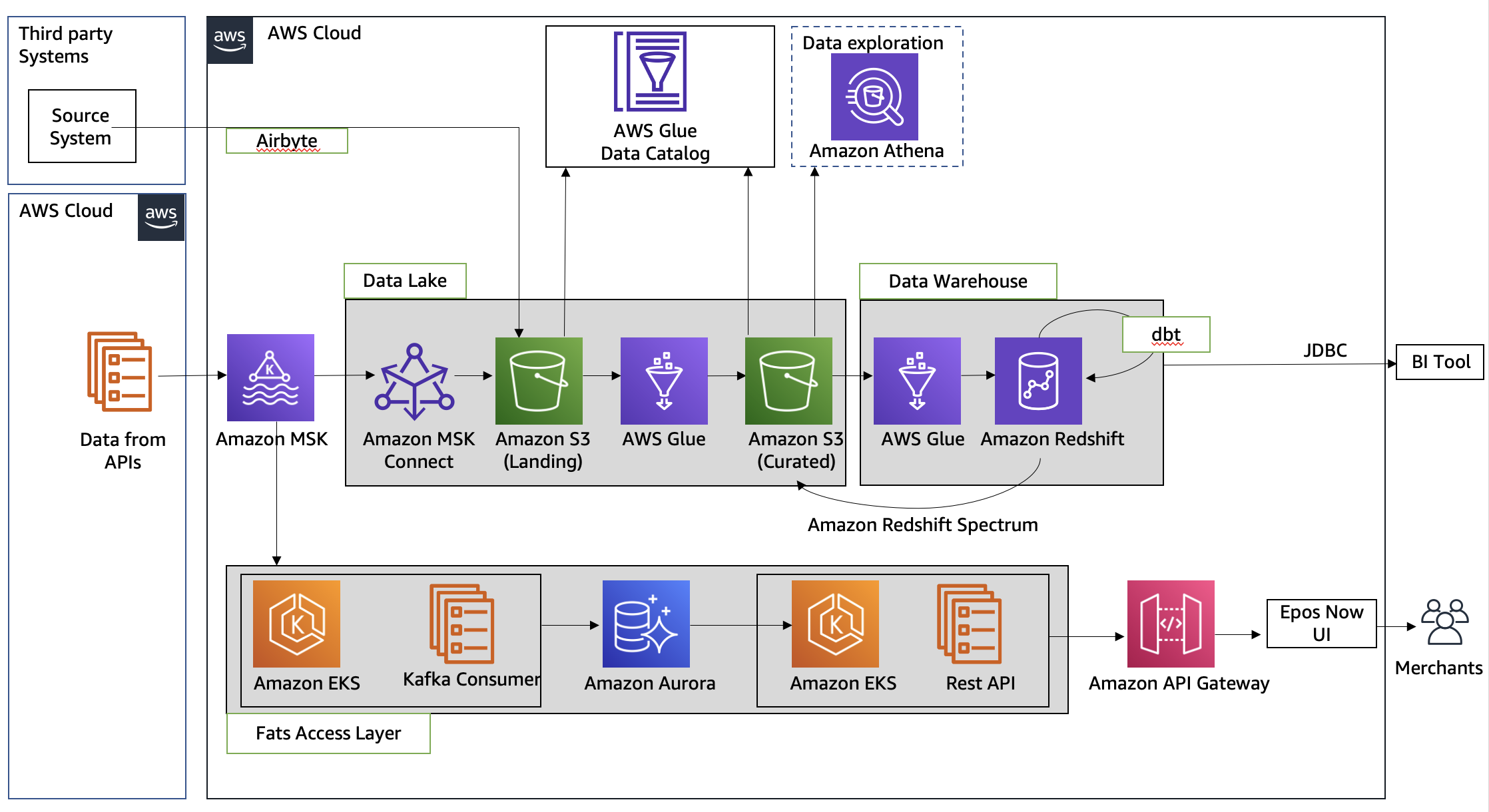
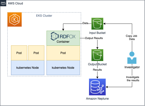
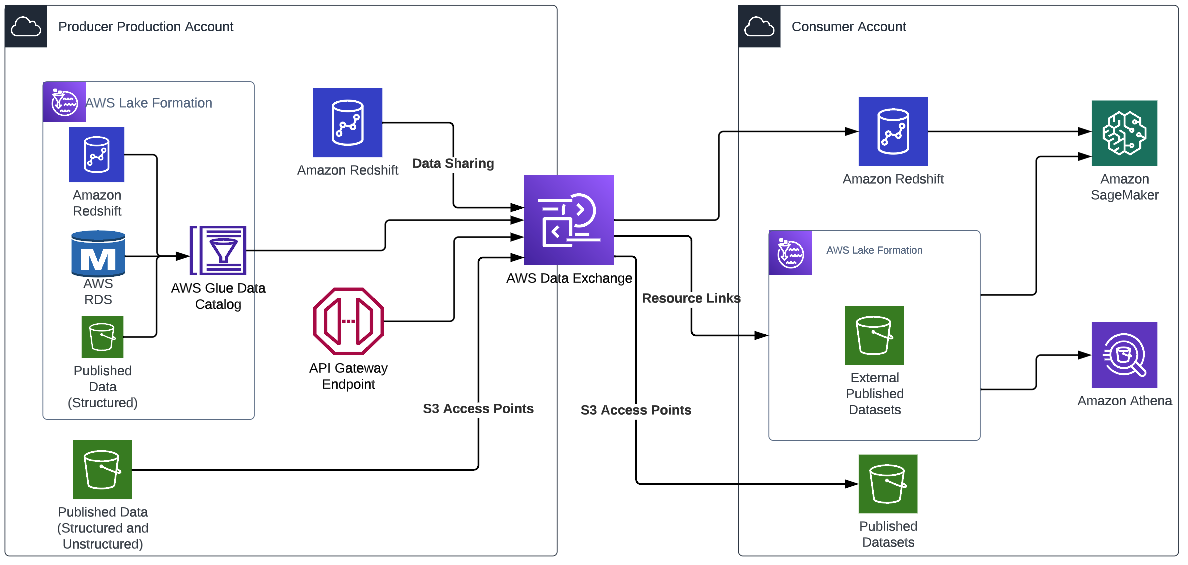
The following architecture diagram describes the AWS services and features you will be using.

The workflow includes the following steps:
- You start with configuring an Amazon MSK Connect source connector, to create an MSK topic, generate mock data, and write it to the MSK topic. For this post, we work with mock customer data.
- The next step is to connect to a Redshift cluster using the Query Editor v2.
- Finally, you configure an external schema and create a materialized view in Amazon Redshift, to consume the data from the MSK topic. This solution does not rely on an MSK Connect sink connector to export the data from Amazon MSK to Amazon Redshift.
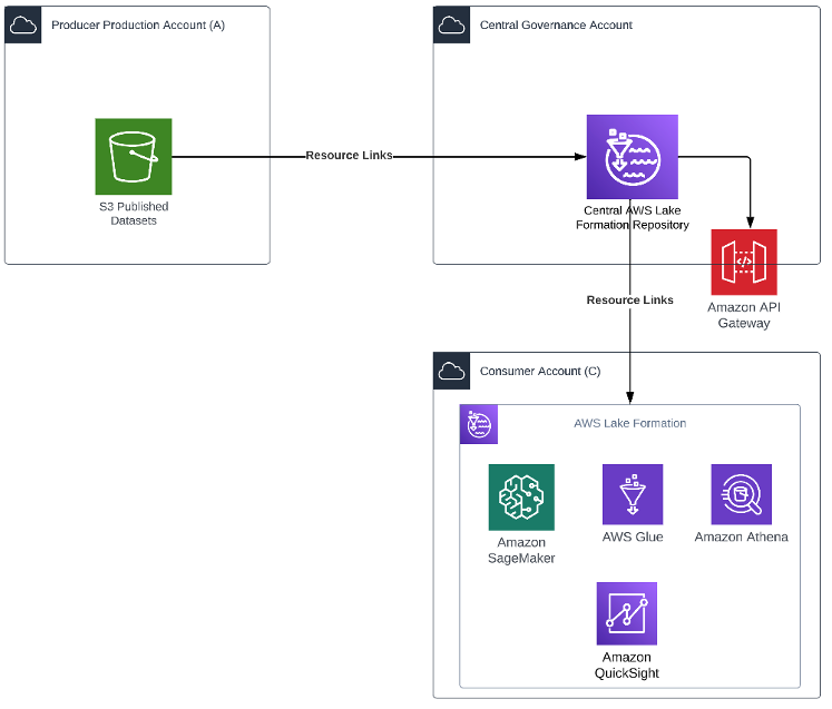
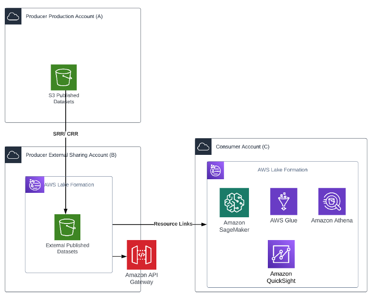
The following solution architecture diagram describes in more detail the configuration and integration of the AWS services you will be using.

The workflow includes the following steps:
- You deploy an MSK Connect source connector, an MSK cluster, and a Redshift cluster within the private subnets on a VPC.
- The MSK Connect source connector uses granular permissions defined in an AWS Identity and Access Management (IAM) in-line policy attached to an IAM role, which allows the source connector to perform actions on the MSK cluster.
- The MSK Connect source connector logs are captured and sent to an Amazon CloudWatch log group.
- The MSK cluster uses a custom MSK cluster configuration, allowing the MSK Connect connector to create topics on the MSK cluster.
- The MSK cluster logs are captured and sent to an Amazon CloudWatch log group.
- The Redshift cluster uses granular permissions defined in an IAM in-line policy attached to an IAM role, which allows the Redshift cluster to perform actions on the MSK cluster.
- You can use the Query Editor v2 to connect to the Redshift cluster.
Prerequisites
To simplify the provisioning and configuration of the prerequisite resources, you can use the following AWS CloudFormation template:
![]()
Complete the following steps when launching the stack:
- For Stack name, enter a meaningful name for the stack, for example,
prerequisites. - Choose Next.
- Choose Next.
- Select I acknowledge that AWS CloudFormation might create IAM resources with custom names.
- Choose Submit.
The CloudFormation stack creates the following resources:
- A VPC
custom-vpc, created across three Availability Zones, with three public subnets and three private subnets:- The public subnets are associated with a public route table, and outbound traffic is directed to an internet gateway.
- The private subnets are associated with a private route table, and outbound traffic is sent to a NAT gateway.
- An internet gateway attached to the Amazon VPC.
- A NAT gateway that is associated with an elastic IP and is deployed in one of the public subnets.
- Three security groups:
msk-connect-sg, which will be later associated with the MSK Connect connector.redshift-sg, which will be later associated with the Redshift cluster.msk-cluster-sg, which will be later associated with the MSK cluster. It allows inbound traffic frommsk-connect-sg, andredshift-sg.
- Two CloudWatch log groups:
msk-connect-logs, to be used for the MSK Connect logs.msk-cluster-logs, to be used for the MSK cluster logs.
- Two IAM Roles:
msk-connect-role, which includes granular IAM permissions for MSK Connect.redshift-role, which includes granular IAM permissions for Amazon Redshift.
- A custom MSK cluster configuration, allowing the MSK Connect connector to create topics on the MSK cluster.
- An MSK cluster, with three brokers deployed across the three private subnets of
custom-vpc. Themsk-cluster-sgsecurity group and thecustom-msk-cluster-configurationconfiguration are applied to the MSK cluster. The broker logs are delivered to themsk-cluster-logsCloudWatch log group. - A Redshift cluster subnet group, which is using the three private subnets of
custom-vpc. - A Redshift cluster, with one single node deployed in a private subnet within the Redshift cluster subnet group. The
redshift-sgsecurity group andredshift-roleIAM role are applied to the Redshift cluster.
Create an MSK Connect custom plugin
For this post, we use an Amazon MSK data generator deployed in MSK Connect, to generate mock customer data, and write it to an MSK topic.
Complete the following steps:
- Download the Amazon MSK data generator JAR file with dependencies from GitHub.

- Upload the JAR file into an S3 bucket in your AWS account.

- On the Amazon MSK console, choose Custom plugins under MSK Connect in the navigation pane.
- Choose Create custom plugin.
- Choose Browse S3, search for the Amazon MSK data generator JAR file you uploaded to Amazon S3, then choose Choose.
- For Custom plugin name, enter
msk-datagen-plugin. - Choose Create custom plugin.


When the custom plugin is created, you will see that its status is Active, and you can move to the next step.

Create an MSK Connect connector
Complete the following steps to create your connector:
- On the Amazon MSK console, choose Connectors under MSK Connect in the navigation pane.
- Choose Create connector.
- For Custom plugin type, choose Use existing plugin.
- Select
msk-datagen-plugin, then choose Next. - For Connector name, enter
msk-datagen-connector. - For Cluster type, choose Self-managed Apache Kafka cluster.
- For VPC, choose
custom-vpc. - For Subnet 1, choose the private subnet within your first Availability Zone.
For the custom-vpc created by the CloudFormation template, we are using odd CIDR ranges for public subnets, and even CIDR ranges for the private subnets:
-
- The CIDRs for the public subnets are 10.10.1.0/24, 10.10.3.0/24, and 10.10.5.0/24
- The CIDRs for the private subnets are 10.10.2.0/24, 10.10.4.0/24, and 10.10.6.0/24
- For Subnet 2, select the private subnet within your second Availability Zone.
- For Subnet 3, select the private subnet within your third Availability Zone.
- For Bootstrap servers, enter the list of bootstrap servers for TLS authentication of your MSK cluster.
To retrieve the bootstrap servers for your MSK cluster, navigate to the Amazon MSK console, choose Clusters, choose msk-cluster, then choose View client information. Copy the TLS values for the bootstrap servers.
- For Security groups, choose Use specific security groups with access to this cluster, and choose
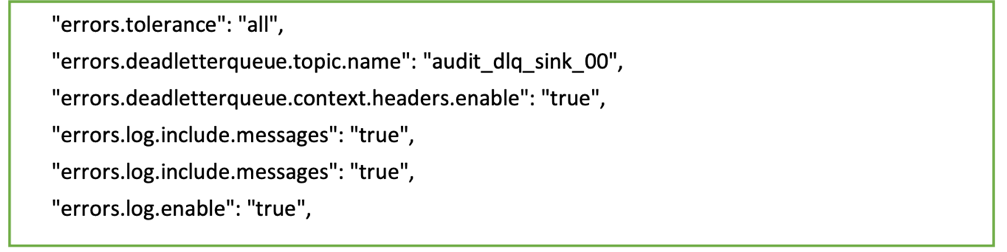
msk-connect-sg. - For Connector configuration, replace the default settings with the following:
- For Connector capacity, choose Provisioned.
- For MCU count per worker, choose 1.
- For Number of workers, choose 1.
- For Worker configuration, choose Use the MSK default configuration.
- For Access permissions, choose
msk-connect-role. - Choose Next.
- For Encryption, select TLS encrypted traffic.
- Choose Next.
- For Log delivery, choose Deliver to Amazon CloudWatch Logs.
- Choose Browse, select
msk-connect-logs, and choose Choose. - Choose Next.
- Review and choose Create connector.
After the custom connector is created, you will see that its status is Running, and you can move to the next step.

Configure Amazon Redshift streaming ingestion for Amazon MSK
Complete the following steps to set up streaming ingestion:
- Connect to your Redshift cluster using Query Editor v2, and authenticate with the database user name
awsuser, and passwordAwsuser123. - Create an external schema from Amazon MSK using the following SQL statement.
In the following code, enter the values for the redshift-role IAM role, and the msk-cluster cluster ARN.
- Choose Run to run the SQL statement.

- Create a materialized view using the following SQL statement:
- Choose Run to run the SQL statement.

- You can now query the materialized view using the following SQL statement:
- Choose Run to run the SQL statement.

- To monitor the progress of records loaded via streaming ingestion, you can take advantage of the SYS_STREAM_SCAN_STATES monitoring view using the following SQL statement:
- Choose Run to run the SQL statement.

- To monitor errors encountered on records loaded via streaming ingestion, you can take advantage of the SYS_STREAM_SCAN_ERRORS monitoring view using the following SQL statement:
- Choose Run to run the SQL statement.


Clean up
After following along, if you no longer need the resources you created, delete them in the following order to prevent incurring additional charges:
- Delete the MSK Connect connector
msk-datagen-connector. - Delete the MSK Connect plugin
msk-datagen-plugin. - Delete the Amazon MSK data generator JAR file you downloaded, and delete the S3 bucket you created.
- After you delete your MSK Connect connector, you can delete the CloudFormation template. All the resources created by the CloudFormation template will be automatically deleted from your AWS account.
Conclusion
In this post, we demonstrated how to configure Amazon Redshift streaming ingestion from Amazon MSK, with a focus on privacy and security.
The combination of the ability of Amazon MSK to handle high throughput data streams with the robust analytical capabilities of Amazon Redshift empowers business to derive actionable insights promptly. This real-time data integration enhances the agility and responsiveness of organizations in understanding changing data trends, customer behaviors, and operational patterns. It allows for timely and informed decision-making, thereby gaining a competitive edge in today’s dynamic business landscape.
This solution is also applicable for customers that are looking to use Amazon MSK Serverless and Amazon Redshift Serverless.
We hope this post was a good opportunity to learn more about AWS service integration and configuration. Let us know your feedback in the comments section.
About the authors
 Sebastian Vlad is a Senior Partner Solutions Architect with Amazon Web Services, with a passion for data and analytics solutions and customer success. Sebastian works with enterprise customers to help them design and build modern, secure, and scalable solutions to achieve their business outcomes.
 Sharad Pai is a Lead Technical Consultant at AWS. He specializes in streaming analytics and helps customers build scalable solutions using Amazon MSK and Amazon Kinesis. He has over 16 years of industry experience and is currently working with media customers who are hosting live streaming platforms on AWS, managing peak concurrency of over 50 million. Prior to joining AWS, Sharad’s career as a lead software developer included 9 years of coding, working with open source technologies like JavaScript, Python, and PHP.


 Satesh Sonti is a Sr. Analytics Specialist Solutions Architect based out of Atlanta, specialized in building enterprise data platforms, data warehousing, and analytics solutions. He has over 18 years of experience in building data assets and leading complex data platform programs for banking and insurance clients across the globe.
 Alket Memushaj works as a Principal Architect in the Financial Services Market Development team at AWS. Alket is responsible for technical strategy for capital markets, working with partners and customers to deploy applications across the trade lifecycle to the AWS Cloud, including market connectivity, trading systems, and pre- and post-trade analytics and research platforms.
 Ruben Falk is a Capital Markets Specialist focused on AI and data & analytics. Ruben consults with capital markets participants on modern data architecture and systematic investment processes. He joined AWS from S&P Global Market Intelligence where he was Global Head of Investment Management Solutions.
 Jeff Wilson is a World-wide Go-to-market Specialist with 15 years of experience working with analytic platforms. His current focus is sharing the benefits of using Amazon Redshift, Amazon’s native cloud data warehouse. Jeff is based in Florida and has been with AWS since 2019.


 Pramod Nayak is the Director of Product Management of the Low Latency Group at LSEG. Pramod has over 10 years of experience in the financial technology industry, focusing on software development, analytics, and data management. Pramod is a former software engineer and passionate about market data and quantitative trading.
 LakshmiKanth Mannem is a Product Manager in the Low Latency Group of LSEG. He focuses on data and platform products for the low-latency market data industry. LakshmiKanth helps customers build the most optimal solutions for their market data needs.
 Vivek Aggarwal is a Senior Data Engineer in the Low Latency Group of LSEG. Vivek works on developing and maintaining data pipelines for processing and delivery of captured market data feeds and reference data feeds.


 Venkata Sistla is a Cloud Architect – Data & Analytics at AWS. He specializes in building data processing capabilities and helping customers remove constraints that prevent them from leveraging their data to develop business insights.
 Santosh Chiplunkar is a Principal Resident Architect at AWS. He has over 20 years of experience helping customers solve their data challenges. He helps customers develop their data and analytics strategy and provides them with guidance on how to make it a reality.
 Martin Zoellner is an IT Specialist at BMW Group. His role in the project is Subject Matter Expert for DevOps and ETL/SW Architecture.
 Thomas Ehrlich is the functional maintenance manager of Regulatory Reporting application in one of the European BMW market.
 Veronika Bogusch is an IT Specialist at BMW. She initiated the rebuild of the Financial Services Batch Integration Layer via the Cloud Data Hub. The ingested data assets are the base for the Regulatory Reporting use case described in this article.
 George Komninos is a solutions architect for the Amazon Web Services (AWS) Data Lab. He helps customers convert their ideas to a production-ready data product. Before AWS, he spent three years at Alexa Information domain as a data engineer. Outside of work, George is a football fan and supports the greatest team in the world, Olympiacos Piraeus.
 Rahul Shaurya is a Senior Big Data Architect with AWS Professional Services. He helps and works closely with customers building data platforms and analytical applications on AWS. Outside of work, Rahul loves taking long walks with his dog Barney.