Tag Archives: Financial Services

OSPAR 2022 report now available with 142 services in scope

Post Syndicated from Joseph Goh original https://aws.amazon.com/blogs/security/ospar-2022-report-now-available-with-142-services-in-scope/

We’re excited to announce the completion of our annual Outsourced Service Provider’s Audit Report (OSPAR) audit cycle on July 1, 2022. The 2022 OSPAR certification cycle includes the addition of 15 new services in scope, bringing the total number of services in scope to 142 in the AWS Asia Pacific (Singapore) Region.

Newly added services in scope include the following:

Successful completion of the OSPAR assessment demonstrates that AWS has a system of controls in place that meet the Association of Banks in Singapore (ABS) Guidelines on Control Objectives and Procedures for Outsourced Service Providers. Our alignment with the ABS guidelines demonstrates our commitment to meet the security expectations for cloud service providers set by the financial services industry in Singapore. Customers can use the OSPAR assessment to conduct due diligence, and to help reduce the effort and costs required for compliance. An independent third-party auditor, selected from the ABS list of approved auditors, performs the OSPAR assessment.

You can download the latest OSPAR report from AWS Artifact, a self-service portal for on-demand access to AWS compliance reports. Sign in to AWS Artifact in the AWS Management Console, or learn more at Getting Started with AWS Artifact. The list of services in scope for OSPAR is available in the report, and is also available on the AWS Services in Scope by Compliance Program webpage.

As always, we’re committed to bringing new services into the scope of our OSPAR program based on your architectural and regulatory needs. If you have questions about the OSPAR report, contact your AWS account team.

 
If you have feedback about this post, submit comments in the Comments section below.

Want more AWS Security how-to content, news, and feature announcements? Follow us on Twitter.

Joseph Goh

Joseph Goh

Joseph is the APJ ASEAN Lead at AWS based in Singapore. He leads security audits, certifications and compliance programs across the Asia Pacific region. Joseph is passionate about delivering programs that build trust with customers and provide them assurance on cloud security.

New AWS whitepaper: AWS User Guide to Financial Services Regulations and Guidelines in New Zealand

Post Syndicated from Julian Busic original https://aws.amazon.com/blogs/security/new-aws-whitepaper-aws-user-guide-to-financial-services-regulations-and-guidelines-in-new-zealand/

Amazon Web Services (AWS) has released a new whitepaper to help financial services customers in New Zealand accelerate their use of the AWS Cloud.

The new AWS User Guide to Financial Services Regulations and Guidelines in New Zealand—along with the existing AWS Workbook for the RBNZ’s Guidance on Cyber Resilience—continues our efforts to help AWS customers navigate the regulatory expectations of the Reserve Bank of New Zealand (RBNZ) in a shared responsibility environment.

This whitepaper is intended for RBNZ-regulated institutions that are looking to run material workloads in the AWS Cloud, and is particularly useful for leadership, security, risk, and compliance teams that need to understand RBNZ requirements and guidance.

The whitepaper summarizes RBNZ requirements and guidance related to outsourcing, cyber resilience, and the cloud. It also gives RBNZ-regulated institutions information they can use to commence their due diligence and assess how to implement the appropriate programs for their use of AWS cloud services.

This document joins existing guides for other jurisdictions in the Asia Pacific region, such as Australia, India, Singapore, and Hong Kong. As the regulatory environment continues to evolve, we’ll provide further updates on the AWS Security Blog and the AWS Compliance page. You can find more information on cloud-related regulatory compliance at the AWS Compliance Center. You can also reach out to your AWS account manager for help finding the resources you need.

 
If you have feedback about this post, submit comments in the Comments section below. If you have questions about this post, contact AWS Support.

Want more AWS Security news? Follow us on Twitter.

Author

Julian Busic

Julian is a Security Solutions Architect with a focus on regulatory engagement. He works with our customers, their regulators, and AWS teams to help customers raise the bar on secure cloud adoption and usage. Julian has over 15 years of experience working in risk and technology across the financial services industry in Australia and New Zealand.

Monitoring and alerting break-glass access in an AWS Organization

Post Syndicated from Haresh Nandwani original https://aws.amazon.com/blogs/architecture/monitoring-and-alerting-break-glass-access-in-an-aws-organization/

Organizations building enterprise-scale systems require the setup of a secure and governed landing zone to deploy and operate their systems. A landing zone is a starting point from which your organization can quickly launch and deploy workloads and applications with confidence in your security and infrastructure environment as described in What is a landing zone?. Nationwide Building Society (Nationwide) is the world’s largest building society. It is owned by its 16 million members and exists to serve their needs. The Society is one of the UK’s largest providers for mortgages, savings and current accounts, as well as being a major provider of ISAs, credit cards, personal loans, insurance, and investments.

For one of its business initiatives, Nationwide utilizes AWS Control Tower to build and operate their landing zone which provides a well-established pattern to set up and govern a secure, multi-account AWS environment. Nationwide operates in a highly regulated industry and our governance assurance requires adequate control of any privileged access to production line-of-business data or to resources which have access to them. We chose for this specific business initiative to deploy our landing zone using AWS Organizations, to benefit from ongoing account management and governance as aligned with AWS implementation best practices. We also utilized AWS Single Sign-On (AWS SSO) to create our workforce identities in AWS once and manage access centrally across our AWS Organization. In this blog, we describe the integrations required across AWS Control Tower and AWS SSO to implement a break-glass mechanism that makes access reporting publishable to system operators as well as to internal audit systems and processes. We will outline how we used AWS SSO for our setup as well as the three architecture options we considered, and why we went with the chosen solution.

Sourcing AWS SSO access data for near real-time monitoring

In our setup, we have multiple AWS Accounts and multiple trails on each of these accounts. Users will regularly navigate across multiple accounts as they operate our infrastructure, and their journeys are marked across these multiple trails. Typically, AWS CloudTrail would be our chosen resource to clearly and unambiguously identify account or data access.  The key challenge in this scenario was to design an efficient and cost-effective solution to scan these trails to help identify and report on break-glass user access to account and production data. To address this challenge, we developed the following two architecture design options.

Option 1: A decentralized approach that uses AWS CloudFormation StackSets, Amazon EventBridge and AWS Lambda

Our solution entailed a decentralized approach by deploying a CloudFormation StackSet to create, update, or delete stacks across multiple accounts and AWS Regions with a single operation. The Stackset created Amazon EventBridge rules and target AWS Lambda functions. These functions post to EventBridge in our audit account. Our audit account has a set of Lambda functions running off EventBridge to initiate specific events, format the event message and post to Slack, our centralized communication platform for this implementation. Figure 1 depicts the overall architecture for this option.

De-centralized logging using Amazon EventBridge and AWS Lambda

Figure 1. De-centralized logging using Amazon EventBridge and AWS Lambda

Option 2: Use an organization trail in the Organization Management account

This option uses the centralized organization trail in the Organization Management account to source audit data. Details of how to create an organization trail can be found in the AWS CloudTrail User Guide. CloudTrail was configured to send log events to CloudWatch Logs. These events are then sent via Lambda functions to Slack using webhooks. We used a public terraform module in this GitHub repository to build this Lambda Slack integration. Figure 2 depicts the overall architecture for this option.

Centralized logging pattern using Amazon CloudWatch

Figure 2. Centralized logging pattern using Amazon CloudWatch

This was our preferred option and is the one we finally implemented.

We also evaluated a third option which was to use centralized logging and auditing feature enabled by Control Tower. Users authenticate and federate to target accounts from a central location so it seemed possible to source this info from the centralized logs. These log events arrive as .gz compressed json objects, which meant having to expand these archives repeatedly for inspection. We therefore decided against this option.

A centralized, economic, extensible solution to alert of SSO break-glass

Our requirement was to identify break-glass access across any of the access mechanisms supported by AWS, including CLI and User Portal access. To ensure we have comprehensive coverage across all access mechanisms, we identified all the events initiated for each access mechanism:

  1. User Portal/AWS Console access events
    • Authenticate
    • ListApplications
    • ListApplicationProfiles
    • Federate – this event contains the role that the user is federating into
  2. CLI access events
    • CreateToken
    • ListAccounts
    • ListAccountRoles
    • GetRoleCredentials – this event contains the role that the user is federating into

EventBridge is able to initiate actions after events only when the event is trying to perform changes (when the “readOnly” attribute on the event record body equals “false”).

The AWS support team was aware of this attribute and recommended that we, change the data flow we were using to one able to initiate actions after any kind of event, regardless of the value on its readOnly attribute. The solution in our case was to send the CloudTrail logs to CloudWatch Logs. This then and initiates the Lambda function through a filter subscription that detects the desired event names on the log content.

The filter used is as follows:

{($.eventSource = sso.amazonaws.com) && ($.eventName = Federate||$.eventName = GetRoleCredentials)}

Due to the query size in the CloudWatch Log queries we had to remove the subscription filters and do the parsing of the content of the log lines inside the lambda function. In order to determine what accounts would initiate the notifications, we sent the list of accounts and roles to it as an environment variable at runtime.

Considerations with cross-account SSO access

With direct federation users get an access token. This is most obvious in AWS single sign on at the chiclet page as “Command line or programmatic access”. SSO tokens have a limited lifetime (we use the default 1-hour). A user does not have to get a new token to access a target resource until the one they are using is expired. This means that a user may repeatedly access a target account using the same token during its lifetime. Although the token is made available at the chiclet page, the GetRoleCredentials event does not occur until it is used to authenticate an API call to the target AWS account.

Conclusion

In this blog, we discussed how AWS Control Tower and AWS Single Sign-on enabled Nationwide to build and govern a secure, multi-account AWS environment for one of their business initiatives and centralize access management across our implementation. The integration was important for us to accurately and comprehensively identify and audit break-glass access for our implementation. As a result, we were able to satisfy our security and compliance audit requirements for privileged access to our AWS accounts.

AWS User Guide to Financial Services Regulations and Guidelines in Switzerland and FINMA workbooks publications

Post Syndicated from Margo Cronin original https://aws.amazon.com/blogs/security/aws-user-guide-to-financial-services-regulations-and-guidelines-in-switzerland-and-finma/

AWS is pleased to announce the publication of the AWS User Guide to Financial Services Regulations and Guidelines in Switzerland whitepaper and workbooks.

This guide refers to certain rules applicable to financial institutions in Switzerland, including banks, insurance companies, stock exchanges, securities dealers, portfolio managers, trustees and other financial entities which are overseen (directly or indirectly) by the Swiss Financial Market Supervisory Authority (FINMA).

Amongst other topics, this guide covers requirements created by the following regulations and publications of interest to Swiss financial institutions:

  • Federal Laws – including Article 47 of the Swiss Banking Act (BA). Banks and Savings Banks are overseen by FINMA and governed by the BA (Bundesgesetz über die Banken und Sparkassen, Bankengesetz, BankG). Article 47 BA holds relevance in the context of outsourcing.
  • Response on Cloud Guidelines for Swiss Financial institutions produced by the Swiss Banking Union, Schweizerische Bankiervereinigung SBVg.
  • Controls outlined by FINMA, Switzerland’s independent regulator of financial markets, that may be applicable to Swiss banks and insurers in the context of outsourcing arrangements to the cloud.

In combination with the AWS User Guide to Financial Services Regulations and Guidelines in Switzerland whitepaper, customers can use the detailed AWS FINMA workbooks and ISAE 3000 report available from AWS Artifact.

The five core FINMA circulars are intended to assist Swiss-regulated financial institutions in understanding approaches to due diligence, third-party management, and key technical and organizational controls that should be implemented in cloud outsourcing arrangements, particularly for material workloads. The AWS FINMA workbooks and ISAE 3000 report scope covers, in detail, requirements of the following FINMA circulars:

  • 2018/03 Outsourcing – banks and insurers (04.11.2020)
  • 2008/21 Operational Risks – Banks – Principle 4 Technology Infrastructure (31.10.2019)
  • 2008/21 Operational Risks – Banks – Appendix 3 Handling of electronic Client Identifying Data (31.10.2019)
  • 2013/03 Auditing – Information Technology (04.11.2020)
  • 2008/10 Self-regulation as a minimum standard – Minimum Business Continuity Management (BCM) minimum standards proposed by the Swiss Insurance Association (01.06.2015) and Swiss Bankers Association (29.08.2013)

Customers can use the detailed FINMA workbooks, which include detailed control mappings for each FINMA control, covering both the AWS control activities and the Customer User Entity Controls. Where applicable, under the AWS Shared Responsibility Model, these workbooks provide industry standard practices, incorporating AWS Well-Architected, to assist Swiss customers in their own preparation for FINMA circular alignment.

This whitepaper follows the issuance of the second Swiss Financial Market Supervisory Authority (FINMA) ISAE 3000 Type 2 attestation report. The latest report covers the period from October 1, 2020 to September 30, 2021, with a total of 141 AWS services and 23 global AWS Regions included in the scope. Customers can download the report from AWS Artifact. A full list of certified services and Regions is presented within the published FINMA report.

As always, AWS is committed to bringing new services into the scope of our FINMA program in the future based on customers’ architectural and regulatory needs. Please reach out to your AWS account team if you have any questions or feedback. If you have questions about this post, contact AWS Support.

Want more AWS Security news? Follow us on Twitter.

Author

Margo Cronin

Margo is a Principal Security Specialist at Amazon Web Services based in Zurich, Switzerland. She spends her days working with customers, from startups to the largest of enterprises, helping them build new capabilities and accelerating their cloud journey. She has a strong focus on security, helping customers improve their security, risk, and compliance in the cloud.

Doing more with less: Moving from transactional to stateful batch processing

Post Syndicated from Tom Jin original https://aws.amazon.com/blogs/big-data/doing-more-with-less-moving-from-transactional-to-stateful-batch-processing/

Amazon processes hundreds of millions of financial transactions each day, including accounts receivable, accounts payable, royalties, amortizations, and remittances, from over a hundred different business entities. All of this data is sent to the eCommerce Financial Integration (eCFI) systems, where they are recorded in the subledger.

Ensuring complete financial reconciliation at this scale is critical to day-to-day accounting operations. With transaction volumes exhibiting double-digit percentage growth each year, we found that our legacy transactional-based financial reconciliation architecture proved too expensive to scale and lacked the right level of visibility for our operational needs.

In this post, we show you how we migrated to a batch processing system, built on AWS, that consumes time-bounded batches of events. This not only reduced costs by almost 90%, but also improved visibility into our end-to-end processing flow. The code used for this post is available on GitHub.

Legacy architecture

Our legacy architecture primarily utilized Amazon Elastic Compute Cloud (Amazon EC2) to group related financial events into stateful artifacts. However, a stateful artifact could refer to any persistent artifact, such as a database entry or an Amazon Simple Storage Service (Amazon S3) object.

We found this approach resulted in deficiencies in the following areas:

  • Cost – Individually storing hundreds of millions of financial events per day in Amazon S3 resulted in high I/O and Amazon EC2 compute resource costs.
  • Data completeness – Different events flowed through the system at different speeds. For instance, while a small stateful artifact for a single customer order could be recorded in a couple of seconds, the stateful artifact for a bulk shipment containing a million lines might require several hours to update fully. This made it difficult to know whether all the data had been processed for a given time range.
  • Complex retry mechanisms – Financial events were passed between legacy systems using individual network calls, wrapped in a backoff retry strategy. Still, network timeouts, throttling, or traffic spikes could result in some events erroring out. This required us to build a separate service to sideline, manage, and retry problematic events at a later date.
  • Scalability – Bottlenecks occurred when different events competed to update the same stateful artifact. This resulted in excessive retries or redundant updates, making it less cost-effective as the system grew.
  • Operational support – Using dedicated EC2 instances meant that we needed to take valuable development time to manage OS patching, handle host failures, and schedule deployments.

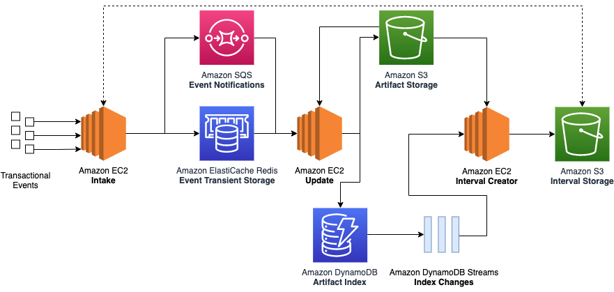
The following diagram illustrates our legacy architecture.

Transactional-based legacy architecture

Evolution is key

Our new architecture needed to address the deficiencies while preserving the core goal of our service: update stateful artifacts based on incoming financial events. In our case, a stateful artifact refers to a group of related financial transactions used for reconciliation. We considered the following as part of the evolution of our stack:

  • Stateless and stateful separation
  • Minimized end-to-end latency
  • Scalability

Stateless and stateful separation

In our transactional system, each ingested event results in an update to a stateful artifact. This became a problem when thousands of events came in all at once for the same stateful artifact.

However, by ingesting batches of data, we had the opportunity to create separate stateless and stateful processing components. The stateless component performs an initial reduce operation on the input batch to group together related events. This meant that the rest of our system could operate on these smaller stateless artifacts and perform fewer write operations (fewer operations means lower costs).

The stateful component would then join these stateless artifacts with existing stateful artifacts to produce an updated stateful artifact.

As an example, imagine an online retailer suddenly received thousands of purchases for a popular item. Instead of updating an item database entry thousands of times, we can first produce a single stateless artifact that summaries the latest purchases. The item entry can now be updated one time with the stateless artifact, reducing the update bottleneck. The following diagram illustrates this process.

Batch visualization

Minimized end-to-end latency

Unlike traditional extract, transform, and load (ETL) jobs, we didn’t want to perform daily or even hourly extracts. Our accountants need to be able to access the updated stateful artifacts within minutes of data arriving in our system. For instance, if they had manually sent a correction line, they wanted to be able to check within the same hour that their adjustment had the intended effect on the targeted stateful artifact instead of waiting until the next day. As such, we focused on parallelizing the incoming batches of data as much as possible by breaking down the individual tasks of the stateful component into subcomponents. Each subcomponent could run independently of each other, which allowed us to process multiple batches in an assembly line format.

Scalability

Both the stateless and stateful components needed to respond to shifting traffic patterns and possible input batch backlogs. We also wanted to incorporate serverless compute to better respond to scale while reducing the overhead of maintaining an instance fleet.

This meant we couldn’t simply have a one-to-one mapping between the input batch and stateless artifact. Instead, we built flexibility into our service so the stateless component could automatically detect a backlog of input batches and group multiple input batches together in one job. Similar backlog management logic was applied to the stateful component. The following diagram illustrates this process.

Batch scalability

Current architecture

To meet our needs, we combined multiple AWS products:

  • AWS Step Functions – Orchestration of our stateless and stateful workflows
  • Amazon EMR – Apache Spark operations on our stateless and stateful artifacts
  • AWS Lambda – Stateful artifact indexing and orchestration backlog management
  • Amazon ElastiCache – Optimizing Amazon S3 request latency
  • Amazon S3 – Scalable storage of our stateless and stateful artifacts
  • Amazon DynamoDB – Stateless and stateful artifact index

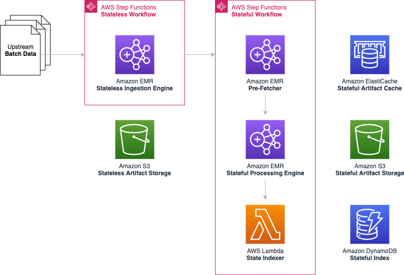
The following diagram illustrates our current architecture.

Current architecture

The following diagram shows our stateless and stateful workflow.

Flowchart

The AWS CloudFormation template to render this architecture and corresponding Java code is available in the following GitHub repo.

Stateless workflow

We used an Apache Spark application on a long-running Amazon EMR cluster to simultaneously ingest input batch data and perform reduce operations to produce the stateless artifacts and a corresponding index file for the stateful processing to use.

We chose Amazon EMR for its proven highly available data-processing capability in a production setting and also its ability to horizontally scale when we see increased traffic loads. Most importantly, Amazon EMR had lower cost and better operational support when compared to a self-managed cluster.

Stateful workflow

Each stateful workflow performs operations to create or update millions of stateful artifacts using the stateless artifacts. Similar to the stateless workflows, all stateful artifacts are stored in Amazon S3 across a handful of Apache Spark part-files. This alone resulted in a huge cost reduction, because we significantly reduced the number of Amazon S3 writes (while using the same amount of overall storage). For instance, storing 10 million individual artifacts using the transactional legacy architecture would cost $50 in PUT requests alone, whereas 10 Apache Spark part-files would cost only $0.00005 in PUT requests (based on $0.005 per 1,000 requests).

However, we still needed a way to retrieve individual stateful artifacts, because any stateful artifact could be updated at any point in the future. To do this, we turned to DynamoDB. DynamoDB is a fully managed and scalable key-value and document database. It’s ideal for our access pattern because we wanted to index the location of each stateful artifact in the stateful output file using its unique identifier as a primary key. We used DynamoDB to index the location of each stateful artifact within the stateful output file. For instance, if our artifact represented orders, we would use the order ID (which has high cardinality) as the partition key, and store the file location, byte offset, and byte length of each order as separate attributes. By passing the byte-range in Amazon S3 GET requests, we can now fetch individual stateful artifacts as if they were stored independently. We were less concerned about optimizing the number of Amazon S3 GET requests because the GET requests are over 10 times cheaper than PUT requests.

Overall, this stateful logic was split across three serial subcomponents, which meant that three separate stateful workflows could be operating at any given time.

Pre-fetcher

The following diagram illustrates our pre-fetcher subcomponent.

Prefetcher architecture

The pre-fetcher subcomponent uses the stateless index file to retrieve pre-existing stateful artifacts that should be updated. These might be previous shipments for the same customer order, or past inventory movements for the same warehouse. For this, we turn once again to Amazon EMR to perform this high-throughput fetch operation.

Each fetch required a DynamoDB lookup and an Amazon S3 GET partial byte-range request. Due to the large number of external calls, fetches were highly parallelized using a thread pool contained within an Apache Spark flatMap operation. Pre-fetched stateful artifacts were consolidated into an output file that was later used as input to the stateful processing engine.

Stateful processing engine

The following diagram illustrates the stateful processing engine.

Stateful processor architecture

The stateful processing engine subcomponent joins the pre-fetched stateful artifacts with the stateless artifacts to produce updated stateful artifacts after applying custom business logic. The updated stateful artifacts are written out across multiple Apache Spark part-files.

Because stateful artifacts could have been indexed at the same time that they were pre-fetched (also called in-flight updates), the stateful processor also joins recently processed Apache Spark part-files.

We again used Amazon EMR here to take advantage of the Apache Spark operations that are required to join the stateless and stateful artifacts.

State indexer

The following diagram illustrates the state indexer.

State Indexer architecture

This Lambda-based subcomponent records the location of each stateful artifact within the stateful part-file in DynamoDB. The state indexer also caches the stateful artifacts in an Amazon ElastiCache for Redis cluster to provide a performance boost in the Amazon S3 GET requests performed by the pre-fetcher.

However, even with a thread pool, a single Lambda function isn’t powerful enough to index millions of stateful artifacts within the 15-minute time limit. Instead, we employ a cluster of Lambda functions. The state indexer begins with a single coordinator Lambda function, which determines the number of worker functions that are needed. For instance, if 100 part-files are generated by the stateful processing engine, then the coordinator might assign five part-files for each of the 20 Lambda worker functions to work on. This method is highly scalable because we can dynamically assign more or fewer Lambda workers as required.

Each Lambda worker then performs the ElastiCache and DynamoDB writes for all the stateful artifacts within each assigned part-file in a multi-threaded manner. The coordinator function monitors the health of each Lambda worker and restarts workers as needed.

Distributed Lambda architecture

Orchestration

We used Step Functions to coordinate each of the stateless and stateful workflows, as shown in the following diagram.

Step Function Workflow

Every time a new workflow step ran, the step was recorded in a DynamoDB table via a Lambda function. This table not only maintained the order in which stateful batches should be run, but it also formed the basis of the backlog management system, which directed the stateless ingestion engine to group more or fewer input batches together depending on the backlog.

We chose Step Functions for its native integration with many AWS services (including triggering by an Amazon CloudWatch scheduled event rule and adding Amazon EMR steps) and its built-in support for backoff retries and complex state machine logic. For instance, we defined different backoff retry rates based on the type of error.

Conclusion

Our batch-based architecture helped us overcome the transactional processing limitations we originally set out to resolve:

  • Reduced cost – We have been able to scale to thousands of workflows and hundreds of million events per day using only three or four core nodes per EMR cluster. This reduced our Amazon EC2 usage by over 90% when compared with a similar transactional system. Additionally, writing out batches instead of individual transactions reduced the number of Amazon S3 PUT requests by over 99.8%.
  • Data completeness guarantees – Because each input batch is associated with a time interval, when a batch has finished processing, we know that all events in that time interval have been completed.
  • Simplified retry mechanisms – Batch processing means that failures occur at the batch level and can be retried directly through the workflow. Because there are far fewer batches than transactions, batch retries are much more manageable. For instance, in our service, a typical batch contains about two million entries. During a service outage, only a single batch needs to be retried, as opposed to two million individual entries in the legacy architecture.
  • High scalability – We’ve been impressed with how easy it is to scale our EMR clusters on the fly if we detect an increase in traffic. Using Amazon EMR instance fleets also helps us automatically choose the most cost-effective instances across different Availability Zones. We also like the performance achieved by our Lambda-based state indexer. This subcomponent not only dynamically scales with no human intervention, but has also been surprisingly cost-efficient. A large portion of our usage has fallen within the free tier.
  • Operational excellence – Replacing traditional hosts with serverless components such as Lambda allowed us to spend less time on compliance tickets and focus more on delivering features for our customers.

We are particularly excited about the investments we have made moving from a transactional-based system to a batch processing system, especially our shift from using Amazon EC2 to using serverless Lambda and big data Amazon EMR services. This experience demonstrates that even services originally built on AWS can still achieve cost reductions and improve performance by rethinking how AWS services are used.

Inspired by our progress, our team is moving to replace many other legacy services with serverless components. Likewise, we hope that other engineering teams can learn from our experience, continue to innovate, and do more with less.

Find the code used for this post in the following GitHub repository.

Special thanks to development team: Ryan Schwartz, Abhishek Sahay, Cecilia Cho, Godot Bian, Sam Lam, Jean-Christophe Libbrecht, and Nicholas Leong.


About the Authors


Tom Jin is a Senior Software Engineer for eCommerce Financial Integration (eCFI) at Amazon. His interests include building large-scale systems and applying machine learning to healthcare applications. He is based in Vancouver, Canada and is a fan of ocean conservation.

Karthik Odapally is a Senior Solutions Architect at AWS supporting our Gaming Customers. He loves presenting at external conferences like AWS Re:Invent, and helping customers learn about AWS. His passion outside of work is to bake cookies and bread for family and friends here in the PNW. In his spare time, he plays Legend of Zelda (Link’s Awakening) with his 4 yr old daughter.

Financial Crime Discovery using Amazon EKS and Graph Databases

Post Syndicated from Severin Gassauer-Fleissner original https://aws.amazon.com/blogs/architecture/financial-crime-discovery-using-amazon-eks-and-graph-databases/

Discovering and solving financial crimes has become a challenge due to an increasing amount of financial data. While storing transactional payment data in a structured table format is useful for searching, filtering, and calculations, it is not always an ideal way to represent transactional data. For example, determining if there is a suspicious financial relationship between entity A and entity B is difficult to visualize in a table. Using tables, we would have to do SQL joins for every possible transaction from entity A to every possible subsequent transaction. We would then have to iterate this process until we found a relationship to entity B. Moreover, certain queries are challenging to run on a relational database management system (RDBMS). For example, it can be quite time consuming to discover which account received a minimum amount of $10,000,000 from other accounts.

Graph databases such as Amazon Neptune can be helpful with performing queries, because they can traverse the data and perform calculations simultaneously. Graphs enable us to represent transactions and parties over a multi-connected network, and discover patterns and chains of connections. It is common to use them in anti-money laundering (AML) applications, as they can help find patterns of suspicious transactions.

We needed a solution that could scale and process millions of transactions, by effectively using high memory and CPU configurations to perform complex queries quickly. As part of our customer demonstration to show how graph databases can help discover financial crimes, we also sourced a large dataset on which to test the solution. We used a graph database, Amazon Elastic Kubernetes Service (EKS), and Amazon Neptune, to search for suspicious financial chains across large amounts of transactional data in minutes.

Overview of our conceptual financial crime discovery solution

Figure 1. Workflow for financial crime discovery

Figure 1. Workflow for financial crime discovery

We first needed to find a rules engine that could perform transaction inferencing and reasoning. It had to be able to process various rules on our data, be efficient, and able to scale. Next, we needed a straightforward way to ingest data into the solution. Once we had the data available, we needed to initiate a task to begin our inference job. Finally, we needed a location to store the result for further analysis and persistence, see Figure 1.

Using the AWS Cloud to scale up a graph database

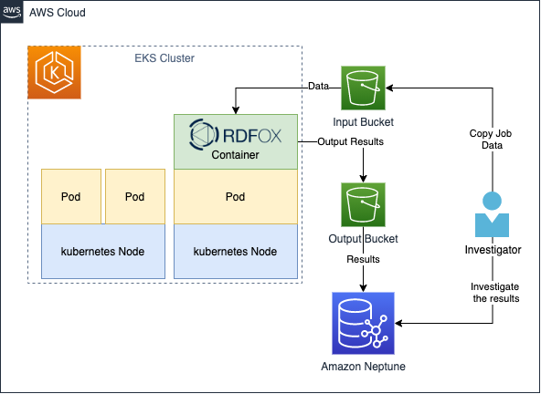
We used multiple AWS services to create a fully automated end-to-end batch-based transaction process, shown in Figure 2. We used RDFox, which is an AWS Marketplace product, created by Oxford Semantic Technologies. RDFox is a high-performance in-memory graph database and semantic reasoner. To orchestrate RDFox, we used Amazon EKS Autoscaler to spin up a cluster to instantiate the RDFox container. Amazon EKS can spin up multiple containers for difference inference jobs and recycle the resources when the job finishes. We also used Amazon Neptune, an Amazon managed distributed graph database that can store up to 64 TiB of the results for diagnosis and long-term retention.

The data is stored in Amazon S3 buckets, which provide a streamlined way to feed a large dataset for processing.

Figure 2. Architecture diagram for financial crime discovery

Figure 2. Architecture diagram for financial crime discovery

Financial crimes rules

The power of graphs can help discover financial crimes that are reflected in relationships and monetary transactions. To demonstrate this, we will write two rules to detect two scenarios:

  1. Given two suspicious parties X and Y, find out if there is a transactional relationship between them, and if so, provide the chain that connects them. This is a common scenario that financial institutions must detect.
  2. Given a chain identifying suspicious behavior, find out if the minimum transaction amount that reached the beneficiary exceeds a threshold of Z dollars.

Generating data

To generate data for testing, we used a synthetic data generator written in Python (see GitHub repo in References). The generator built two sets of graph artifacts – parties and transactions. Every transaction is being paired with two random parties, and this iterative process creates a network of connected transactions and parties.

We created a dataset with a small percentage (0.01%) of parties tagged as “Suspicious Party,” to simulate the preceding business scenario. Note that those parties will have transactions going both in and out. In some cases, this will collide with other suspicious parties and establish a chain. This method enables us to get simulated data without engineering the suspicious chains.
The test dataset used with this solution comprises 1M transactions and thousands of parties.
For more information on generating data, see GitHub: Transaction Chains Data Generator.

Walkthrough of the financial investigator workflow

Once deployed, this solution can assist investigators as follows:

  1. An investigator places the transactions and party data (nt triples) in a subdirectory within the input bucket. Typically, subdirectories can be named as a date or range of dates. In addition, the investigator uploads the particular rules (dlog files) and queries (rq files) that must be processed on the data.
  2. Once the data is ready, the investigator uploads a job spec file (simple JSON, see References section). This contains the description of what resources the job requires (CPUs and memory), along with other configurations for the job.
  3. Once the job spec has been uploaded to the bucket’s subdirectory, the job is automatically initiated. The Kubernetes scheduler will allocate enough resources to initiate the RDFox pod. The containers in the pod will then load, process, query results, and upload them to the output bucket.
  4. Once the data reaches the output bucket, an AWS Lambda function is initiated. This invokes the Amazon Neptune Bulk Loader, which asynchronously loads the results to the Neptune cluster in a parallelized manner.
  5. Once the load completes, the investigator gets an email notification that the job has been completed, and the results are ready for view.

Additionally:

  • The investigator can upload multiple rules and queries, they will all be processed automatically.
  • The investigator can launch multiple jobs with different/same data, and with different rules and queries at the same time.
  • All jobs outputs are saved in a unique job ID subdirectory in the output bucket.

To create the solution in your account, follow the instruction here: GitHub repo

Prerequisites

For this walkthrough, you should have the following prerequisites:

Rules

We create two materialization rule sets to fetch the two scenarios described.

1. detect-suspicious-parties-pair.dlog

The purpose of this first set of rules is to detect chains that might exist between two suspicious parties. The idea of these chains is to represent all the possible relationships that contain monetary transfers between a suspicious originator and the beneficiary. This will include non-suspicious parties in the chain. The rule tags these chains with the “SuspiciousChain” flag.

2. detect-chains-exceed-100-dollars.dlog

This set of rules is designed to tag the chains identified by the first set of rules. It also contains a minimum amount of $100 passed to the beneficiary. We can change the amount to check for different compliance requirements. We tag those chains as “HighValueChain.”

Run the job and check your results

Now we can run our job, with the given data, rules, and two additional queries (to extract “SuspiciousChain” and “HighValueChain” respectively). The result of the queries will be loaded to Amazon Neptune automatically for persistent storage, and is made durably available for further analysis.

Let’s look at the results. The following query can be initiated against RDFox console or Amazon Neptune.

Visualization

PREFIX : <http://oxfordsemantic.tech/transactions/entities#>

PREFIX prop: <http://oxfordsemantic.tech/transactions/properties#>

PREFIX type: <http://oxfordsemantic.tech/transactions/classes#>

PREFIX tt: <http://oxfordsemantic.tech/transactions/tupletables#>

SELECT ?S ?P ?O WHERE {

            ?S a type:SuspiciousChain .

            ?S ?P ?O .

}

Figure 3. Visualizing suspicious chains

Figure 3. Visualizing suspicious chains

Whoa! Figure 3 might look complicated at first, but this is because we are visualizing every pair of suspicious parties that have a relationship with another suspicious party. Let’s filter the query to look only at a single particular chain, which exceeds a minimum of $100 to the beneficiary. The following query can be executed against RDFox console or Amazon Neptune.

PREFIX : <http://oxfordsemantic.tech/transactions/entities#>
PREFIX prop: <http://oxfordsemantic.tech/transactions/properties#>
PREFIX type: <http://oxfordsemantic.tech/transactions/classes#>
PREFIX tt: <http://oxfordsemantic.tech/transactions/tupletables#>

SELECT * WHERE {
?S ?P ?O
{
SELECT ?S WHERE {
?S a type:HighValueChain .

} Limit 1

}

Figure 4. Visualizing a particular chain

Figure 4. Visualizing a particular chain

In Figure 4, we can see that Allison, the suspicious originator of the chain, has sent a transaction to Troy. Troy, who is not suspicious, sent the transaction to Karina. Karina is the suspicious beneficiary. We can also see additional information, such as the transaction amount that Karina received, and the chain length of 2 in this case.

In our testing, we were able to scale up to 500M transactions with 50M parties and process this in less than two hours! And we performed this at a significant lower cost when compared to running constant, fixed similar hardware.

Cleaning up

Follow Terraform cleanup instructions.

Conclusion

Graph databases are a powerful tool to apply reasoning on complex financial relationships. The combination of Amazon Web Services and the RDFox engine results in an automated, scalable, and cost-effective, thanks to the dynamic Kubernetes Cluster Autoscaler. Customers can use this solution and provide their investigators with a tool they can experiment and reason on financial transactions. This solution simplifies the process, and makes it easier to try different rules and queries on complex large data collections.

This blog post is written with Oxford Semantic.

Oxford Semantic Logo

References

Solution:

Further reading

RDFox:

Other:

Comprehensive Cyber Security Framework for Primary (Urban) Cooperative Banks (UCBs)

Post Syndicated from Vikas Purohit original https://aws.amazon.com/blogs/security/comprehensive-cyber-security-framework-for-primary-urban-cooperative-banks/

We are pleased to announce a new Amazon Web Services (AWS) workbook designed to help India Primary (UCBs) customers align with the Reserve Bank of India (RBI) guidance in Comprehensive Cyber Security Framework for Primary (Urban) Cooperative Banks (UCBs) – A Graded Approach.

In addition to RBI’s basic cyber security framework for Primary (Urban) Cooperative Banks (UCBs), RBI issued guidance on its comprehensive cyber security framework, which sets the expectations for the Indian Primary UCBs regarding their cyber security frameworks. This guidance divides the framework into four levels, starting with a common level that applies to all UCBs; the remaining levels apply to specific UCBs based upon their digital depth, and interconnectedness to the payment systems landscape based on RBI-defined criteria. The guidance aims to increase the awareness among the Primary UCBs in India of the controls they should look for as they progress on their digital journey.

Security and compliance is a shared responsibility between AWS and the customer. This differentiation of responsibility is commonly referred to as the AWS Shared Responsibility Model, in which AWS is responsible for security of the cloud, and the customer is responsible for their security in the cloud.

The new AWS Comprehensive Cyber Security Framework for Primary (Urban) Cooperative Banks (UCBs) – A Graded Approach workbook helps customers align with the RBI cyber security framework by providing control mappings for the following:

The downloadable AWS RBI Comprehensive Cyber Security Framework for Primary UCBs workbook is available in AWS Artifact, a self-service portal for on-demand access to AWS Compliance Reports, and it contains two embedded formats:

  • Microsoft Excel: Coverage includes AWS responsibility control statements and Well-Architected Framework best practices
  • Dynamic HTML: Coverage is the same as in the Microsoft Excel format, with the added feature that the Well Architected Framework best practices are mapped to AWS Config managed rules and Amazon GuardDuty findings, where available or applicable.

The AWS RBI Comprehensive Cyber Security Framework for Primary UCBs and AWS RBI Basic Cyber Security Framework for Primary UCBs Workbook are available for download in AWS Artifact. Sign into AWS Artifact via the AWS Management Console, or learn more at Getting Started with AWS Artifact.

If you have feedback about this post, submit comments in the Comments section below.

Want more AWS Security news? Follow us on Twitter.

Vikas Purohit

Vikas Purohit

Vikas works as a Partner Solution Architect with AISPL, India. He helps about helping customers and partners in their cloud journeys. He is particularly passionate in Cloud Security, hybrid networking and migrations.

2021 FINMA ISAE 3000 Type 2 attestation report for Switzerland now available on AWS Artifact

Post Syndicated from Niyaz Noor original https://aws.amazon.com/blogs/security/2021-finma-isae-3000-type-2-attestation-report-for-switzerland-now-available-on-aws-artifact/

AWS is pleased to announce the issuance of a second Swiss Financial Market Supervisory Authority (FINMA) ISAE 3000 Type 2 attestation report. The latest report covers the period from October 1, 2020 to September 30, 2021, with a total of 141 AWS services and 23 global AWS Regions included in the scope.

A full list of certified services and Regions are presented within the published FINMA report; customers can download the latest report from AWS Artifact.

The FINMA ISAE 3000 Type 2 report, conducted by an independent third-party audit firm, provides Swiss financial industry customers with the assurance that the AWS control environment is appropriately designed and implemented to address key operational risks, as well as risks related to outsourcing and business continuity management.

FINMA circulars

The report covers the five core FINMA circulars applicable to Swiss banks and insurers in the context of outsourcing arrangements to the cloud. These FINMA circulars are intended to assist Swiss-regulated financial institutions in understanding approaches to due diligence, third-party management, and key technical and organizational controls that should be implemented in cloud outsourcing arrangements, particularly for material workloads.

The report’s scope covers, in detail, the requirements of the following FINMA circulars:

  • 2018/03 Outsourcing – banks, insurance companies and selected financial institutions under FinIA;
  • 2008/21 Operational Risks – Banks – Principle 4 Technology Infrastructure (31.10.2019);
  • 2008/21 Operational Risks – Banks – Appendix 3 Handling of electronic Client Identifying Data (31.10.2019);
  • 2013/03 Auditing – Information Technology (04.11.2020);
  • 2008/10 Self-regulation as a minimum standard – Minimum Business Continuity Management (BCM) minimum standards proposed by the Swiss Insurance Association (01.06.2015) and Swiss Bankers Association (29.08.2013);

Customers can continue to use the detailed FINMA workbooks that include detailed control mappings for each FINMA circular covered under this audit report; these workbooks are available on AWS Artifact. Where applicable, under the AWS shared responsibility model, these workbooks provide best practices guidance using AWS Well-Architected to assist Swiss customers in their own preparation for alignment with FINMA circulars.

As always, AWS is committed to bringing new services into the future scope of our FINMA program based on customers’ architectural and regulatory needs. Please reach out to your AWS account team if you have questions or feedback about the FINMA report.

If you have feedback about this post, submit comments in the Comments section below.

Want more AWS Security news? Follow us on Twitter.

Author

Niyaz Noor

Niyaz is the Security Audit Program Manager at AWS. Niyaz leads multiple security certification programs across Europe and other regions. During his professional career, he has helped multiple cloud service providers in obtaining global and regional security certification. He is passionate about delivering programs that build customers’ trust and provide them assurance on cloud security.

New AWS workbook for New Zealand financial services customers

Post Syndicated from Julian Busic original https://aws.amazon.com/blogs/security/new-aws-workbook-for-new-zealand-financial-services-customers/

We are pleased to announce a new AWS workbook designed to help New Zealand financial services customers align with the Reserve Bank of New Zealand (RBNZ) Guidance on Cyber Resilience.

The RBNZ Guidance on Cyber Resilience sets out the RBNZ expectations for its regulated entities regarding cyber resilience, and aims to raise awareness and promote the cyber resilience of the financial sector, especially at board and senior management level. The guidance applies to all entities regulated by the RBNZ, including registered banks, licensed non-bank deposit takers, licensed insurers, and designated financial market infrastructures.

While the RBNZ describes its guidance as “a set of recommendations rather than requirements” which are not legally enforceable, it also states that it expects regulated entities to “proactively consider how their current approach to cyber risk management lines up with the recommendations in [the] guidance and look for [opportunities] for improvement as early as possible.”

Security and compliance is a shared responsibility between AWS and the customer. This differentiation of responsibility is commonly referred to as the AWS Shared Responsibility Model, in which AWS is responsible for security of the cloud, and the customer is responsible for their security in the cloud. The new AWS Reserve Bank of New Zealand Guidance on Cyber Resilience (RBNZ-GCR) Workbook helps customers align with the RBNZ Guidance on Cyber Resilience by providing control mappings for the following:

  • Security in the cloud by mapping RBNZ Guidance on Cyber Resilience practices to the five pillars of the AWS Well-Architected Framework.
  • Security of the cloud by mapping RBNZ Guidance on Cyber Resilience practices to control statements from the AWS Compliance Program.

The downloadable AWS RBNZ-GCR Workbook contains two embedded formats:

  • Microsoft Excel – Coverage includes AWS responsibility control statements and Well-Architected Framework best practices.
  • Dynamic HTML – Coverage is the same as in the Microsoft Excel format, with the added feature that the Well-Architected Framework best practices are mapped to AWS Config managed rules and Amazon GuardDuty findings, where available or applicable.

The AWS RBNZ-GCR Workbook is available for download in AWS Artifact, a self-service portal for on-demand access to AWS compliance reports. Sign in to AWS Artifact in the AWS Management Console, or learn more at Getting Started with AWS Artifact.

If you have feedback about this post, submit comments in the Comments section below.

Want more AWS Security how-to content, news, and feature announcements? Follow us on Twitter.

Author

Julian Busic

Julian is a Security Solutions Architect with a focus on regulatory engagement. He works with our customers, their regulators, and AWS teams to help customers raise the bar on secure cloud adoption and usage. Julian has over 15 years of experience working in risk and technology across the financial services industry in Australia and New Zealand.

Build Your Own Game Day to Support Operational Resilience

Post Syndicated from Lewis Taylor original https://aws.amazon.com/blogs/architecture/build-your-own-game-day-to-support-operational-resilience/

Operational resilience is your firm’s ability to provide continuous service through people, processes, and technology that are aware of and adaptive to constant change. Downtime of your mission-critical applications can not only damage your reputation, but can also make you liable to multi-million-dollar financial fines.

One way to test operational resilience is to simulate life-like system failures. An effective way to do this is by running events in your organization known as game days. Game days test systems, processes, and team responses and help evaluate your readiness to react and recover from operational issues. The AWS Well-Architected Framework recommends game days as a key strategy to develop and operate highly resilient systems because they focus not only on technology resilience issues but identify people and process gaps.

This blog post will explain how you can apply game day concepts to your workloads to help achieve a highly resilient workload.

Why does operational resilience matter from a regulatory perspective?

In March 2021, the Bank of England, Prudential Regulation Authority, and Financial Conduct Authority published their Building operational resilience: Feedback to CP19/32 and final rules policy. In this policy, operational resilience refers to a firm’s ability to prevent, adapt, and respond to and return to a steady system state when a disruption occurs. Further, firms are expected to learn and implement process improvements from prior disruptions.

This policy will not apply to everyone. However, across the board if you don’t establish operational resilience strategies, you are likely operating at an increased risk. If you have a service disruption, you may incur lost revenue and reputational damage.

What does it mean to be operationally resilient?

The final policy provides guidance on how firms should achieve operational resilience, which includes but is not limited to the following:

  • Identify and prioritize services based on the potential of intolerable harm to end consumers or risk to market integrity.
  • Define appropriate maximum impact tolerance of an important business service. This is reviewed annually using metrics to measure impact tolerance and answers questions like, “How long (in hours) can a service be offline before causing intolerable harm to end consumers?”
  • Document a complete view of all the aspects required to deliver each important service. This includes people, processes, technology, facilities, and information (resources). Firms should also test their ability to remain within the impact tolerances and provide assurance of resilience along with areas that need to be addressed.

What is a game day?

The AWS Well-Architected Framework defines a game day as follows:

“A game day simulates a failure or event to test systems, processes, and team responses. The purpose is to actually perform the actions the team would perform as if an exceptional event happened. These should be conducted regularly so that your team builds “muscle memory” on how to respond. Your game days should cover the areas of operations, security, reliability, performance, and cost.

In AWS, your game days can be carried out with replicas of your production environment using AWS CloudFormation. This enables you to test in a safe environment that resembles your production environment closely.”

Running game days that simulate system failure helps your organization evaluate and build operational resilience.

How can game days help build operational resilience?

Running a game day alone is not sufficient to ensure operational resilience. However, by navigating the following process to set up and perform a game day, you will establish a best practice-based approach for operating resilient systems.

Stage 1 – Identify key services

As part of setting up a game day event, you will catalog and identify business-critical services.

Game days are performed to test services where operational failure could result in significant financial, customer, and/or reputational impact to the firm. Game days can also evaluate other key factors, like the impact of a failure on the wider market where your firm operates.

For example, a firm may identify its digital banking mobile application from which their customers can initiate payments as one of its important business services.

Stage 2 – Map people, process, and technology supporting the business service

Game days are holistic events. To get a full picture of how the different aspects of your workload operate together, you’ll generate a detailed map of people and processes as they interact and operate the technical and non-technical components of the system. This mapping also helps your end consumers understand how you will provide them reliable support during a failure.

Stage 3 – Define and perform failure scenarios

Systems fail, and failures often happen when a system is operating at scale because various services working together can introduce complexity. To ensure operational resilience, you must understand how systems react and adapt to failures. To do this, you’ll identify and perform failure scenarios so you can understand how your systems will react and adapt and build “muscle memory” for actual events.

AWS builds to guard against outages and incidents, and accounts for them in the design of AWS services—so when disruptions do occur, their impact on customers and the continuity of services is as minimal as possible. At AWS, we employ compartmentalization throughout our infrastructure and services. We have multiple constructs that provide different levels of independent, redundant components.

Stage 4 – Observe and document people, process, and technology reactions

In running a failure scenario, you’ll observe how technological and non-technological components react to and recover from failure. This helps you identify failures and fix them as they cascade through impacted components across your workload. This also helps identify technical and operational challenges that might not otherwise be obvious.

Stage 5 – Conduct lessons learned exercises

Game days generate information on people, processes, and technology and also capture data on customer impact, incident response and remediation timelines, contributing factors, and corrective actions. By incorporating these data points into the system design process, you can implement continuous resilience for critical systems.

How to run your own game day in AWS

You may have heard of AWS GameDay events. This is an AWS organized event for our customers. In this team-based event, AWS provides temporary AWS accounts running fictional systems. Failures are injected into these systems and teams work together on completing challenges and improving the system architecture.

However, the method and tooling and principles we use to conduct AWS GameDays are agnostic and can be applied to your systems using the following services:

  • AWS Fault Injection Simulator is a fully managed service that runs fault injection experiments on AWS, which makes it easier to improve an application’s performance, observability, and resiliency.
  • Amazon CloudWatch is a monitoring and observability service that provides you with data and actionable insights to monitor your applications, respond to system-wide performance changes, optimize resource utilization, and get a unified view of operational health.
  • AWS X-Ray helps you analyze and debug production and distributed applications (such as those built using a microservices architecture). X-Ray helps you understand how your application and its underlying services are performing to identify and troubleshoot the root cause of performance issues and errors.

Please note you are not limited to the tools listed for simulating failure scenarios. For complete coverage of failure scenarios, we encourage you to explore additional tools and strategies.

Figure 1 shows a reference architecture example that demonstrates conducting a game day for an Open Banking implementation.

Game day reference architecture example

Figure 1. Game day reference architecture example

Game day operators use Fault Injection Simulator to catalog and perform failure scenarios to be included in your game day. For example, in our Open Banking use case in Figure 1, a failure scenario might be for the business API functions servicing Open Banking requests to abruptly stop working. You can also combine such simple failure scenarios into a more complex one with failures injected across multiple components of the architecture.

Game day participants use CloudWatch, X-Ray, and their own custom observability and monitoring tooling to identify failures as they cascade through systems.

As you go through the process of identifying, communicating, and fixing issues, you’ll also document impact of failures on end-users. From there, you’ll generate lessons learned to holistically improve your workload’s resilience.

Conclusion

In this blog, we discussed the significance of ensuring operational resilience. We demonstrated how to set up game days and how they can supplement your efforts to ensure operational resilience. We discussed how using AWS services such as Fault Injection Simulator, X-Ray, and CloudWatch can be used to facilitate and implement game day failure scenarios.

Ready to get started? For more information, check out our AWS Fault Injection Simulator User Guide.

Related information:

Disaster recovery compliance in the cloud, part 2: A structured approach

Post Syndicated from Dan MacKay original https://aws.amazon.com/blogs/security/disaster-recovery-compliance-in-the-cloud-part-2-a-structured-approach/

Compliance in the cloud is fraught with myths and misconceptions. This is particularly true when it comes to something as broad as disaster recovery (DR) compliance where the requirements are rarely prescriptive and often based on legacy risk-mitigation techniques that don’t account for the exceptional resilience of modern cloud-based architectures. For regulated entities subject to principles-based supervision such as many financial institutions (FIs), the responsibility lies with the FI to determine what’s necessary to adequately recover from a disaster event. Without clear instructions, FIs are susceptible to making incorrect assumptions regarding their compliance requirements for DR.

In Part 1 of this two-part series, I provided some examples of common misconceptions FIs have about compliance requirements for disaster recovery in the cloud. In Part 2, I outline five steps you can take to avoid these misconceptions when architecting DR-compliant workloads for deployment on Amazon Web Services (AWS).

1. Identify workloads planned for deployment

It’s common for FIs to have a portfolio of workloads they are considering deploying to the cloud and often want to know that they can be compliant across the board. But compliance isn’t a one-size-fits-all domain—it’s based on the characteristics of each workload. For example, does the workload contain personally identifiable information (PII)? Will it be used to store, process, or transmit credit card information? Compliance is dependent on the answers to questions such as these and must be assessed on a case-by-case basis. Therefore, the first step in architecting for compliance is to identify the specific workloads you plan to deploy to the cloud. This way, you can assess the requirements of these specific workloads and not be distracted by aspects of compliance that might not be relevant.

2. Define the workload’s resiliency requirements

Resiliency is the ability of a workload to recover from infrastructure or service disruptions. DR is an important part of your resiliency strategy and concerns how your workload responds to a disaster event. DR strategies on AWS range from simple, low cost options such as backup and restore, to more complex options such as multi-site active-active, as shown in Figure 1.
 

For more information, I encourage you to read Seth Eliot’s blog series on DR Architecture on AWS as well as the AWS whitepaper Disaster Recovery of Workloads on AWS: Recovery in the Cloud.

The DR strategy you choose for a particular workload is dependent on your organization’s requirements for avoiding loss of data—known as the recovery point objective (RPO)—and reducing downtime where the workload isn’t available —known as the recovery time objective (RTO). RPO and RTO are key factors for determining the minimum architectural specifications necessary to meet the workload’s resiliency requirements. For example, can the workload’s RPO and RTO be achieved using a multi-AZ architecture in a single AWS Region, or do the resiliency requirements necessitate deploying the workload across multiple AWS Regions? Even if your workload is not subject to explicit compliance requirements for resiliency, understanding these requirements is necessary for assessing other aspects of DR compliance, including data residency and geodiversity.

3. Confirm the workload’s data residency requirements

As I mentioned in Part 1, data residency requirements might restrict which AWS Region or Regions you can deploy your workload to. Therefore, you need to confirm whether the workload is subject to any data residency requirements within applicable laws and regulations, corporate policies, or contractual obligations.

In order to properly assess these requirements, you must review the explicit language of the requirements so as to understand the specific constraints they impose. You should also consult legal, privacy, and compliance subject-matter specialists to help you interpret these requirements based on the characteristics of the workload. For example, do the requirements specifically state that the data cannot leave the country, or can the requirement be met so long as the data can be accessed from that country? Does the requirement restrict you from storing a copy of the data in another country—for example, for backup and recovery purposes? What if the data is encrypted and can only be read using decryption keys kept within the home country? Consulting subject-matter specialists to help interpret these requirements can help you avoid making overly restrictive assumptions and imposing unnecessary constraints on the workload’s architecture.

4. Confirm the workload’s geodiversity requirements

A single Region, multiple-AZ architecture is often sufficient to meet a workload’s resiliency requirements. However, if the workload is subject to geodiversity requirements, the distance between the AZs in an AWS Region might not conform to the minimum distance between individual data centers specified by the requirements. Therefore, it’s critical to confirm whether any geodiversity requirements apply to the workload.

Like data residency, it’s important to assess the explicit language of geodiversity requirements. Are they written down in a regulation or corporate policy, or are they just a recommended practice? Can the requirements be met if the workload is deployed across three or more AZs even if the minimum distance between those AZs is less than the specified minimum distance between the primary and backup data centers? If it’s a corporate policy, does it allow for exceptions if an alternative method provides equal or greater resiliency than asynchronous replication between two geographically distant data centers? Or perhaps the corporate policy is outdated and should be revised to reflect modern risk mitigation techniques. Understanding these parameters can help you avoid unnecessary constraints as you assess architectural options for your workloads.

5. Assess architectural options to meet the workload’s requirements

Now that you understand the workload’s requirements for resiliency, data residency, and geodiversity, you can assess the architectural options that meet these requirements in the cloud.

As per AWS Well-Architected best practices, you should strive for the simplest architecture necessary to meet your requirements. This includes assessing whether the workload can be accommodated within a single AWS Region. If the workload is constrained by explicit geographic diversity requirements or has resiliency requirements that cannot be accommodated by a single AWS Region, then you might need to architect the workload for deployment across multiple AWS Regions. If the workload is also constrained by explicit data residency requirements, then it might not be possible to deploy to multiple AWS Regions. In cases such as these, you can work with our AWS Solution Architects to assess hybrid options that might meet your compliance requirements, such as using AWS Outposts, Amazon Elastic Container Service (Amazon ECS) Anywhere, or Amazon Elastic Kubernetes Service (Amazon EKS) Anywhere. Another option may be to consider a DR solution in which your on-premises infrastructure is used as a backup for a workload running on AWS. In some cases, this might be a long-term solution. In others, it might be an interim solution until certain constraints can be removed—for example, a change to corporate policy or the introduction of additional AWS Regions in a particular country.

Conclusion

Let’s recap by summarizing some guiding principles for architecting compliant DR workloads as outlined in this two-part series:

  • Avoid assumptions; confirm the facts. If it’s not written down, it’s unlikely to be considered a mandatory compliance requirement.
  • Consult the experts. Legal, privacy, and compliance, as well as AWS Solution Architects, AWS security and compliance specialists, and other subject-matter specialists.
  • Avoid generalities; focus on the specifics. There is no one-size-fits-all approach.
  • Strive for simplicity, not zero risk. Don’t use multiple AWS Regions when one will suffice.
  • Don’t get distracted by exceptions. Focus on your current requirements, not workloads you’re not yet prepared to deploy to the cloud.

If you have feedback about this post, submit comments in the Comments section below.

Want more AWS Security how-to content, news, and feature announcements? Follow us on Twitter.

Author

Dan MacKay

Dan is the Financial Services Compliance Specialist for AWS Canada. As a member of the Worldwide Financial Services Security & Compliance team, Dan advises financial services customers on best practices and practical solutions for cloud-related governance, risk, and compliance. He specializes in helping AWS customers navigate financial services and privacy regulations applicable to the use of cloud technology in Canada.

Disaster recovery compliance in the cloud, part 1: Common misconceptions

Post Syndicated from Dan MacKay original https://aws.amazon.com/blogs/security/disaster-recovery-compliance-in-the-cloud-part-1-common-misconceptions/

Compliance in the cloud can seem challenging, especially for organizations in heavily regulated sectors such as financial services. Regulated financial institutions (FIs) must comply with laws and regulations (often in multiple jurisdictions), global security standards, their own corporate policies, and even contractual obligations with their customers and counterparties. These various compliance requirements may impose constraints on how their workloads can be architected for the cloud, and may require interpretation on what FIs must do in order to be compliant. It’s common for FIs to make assumptions regarding their compliance requirements, which can result in unnecessary costs and increased complexity, and might not align with their strategic objectives. A modern, rationalized approach to compliance can help FIs avoid imposing unnecessary constraints while meeting their mandatory requirements.

In my role as an Amazon Web Services (AWS) Compliance Specialist, I work with our financial services customers to identify, assess, and determine solutions to address their compliance requirements as they move to the cloud. One of the most common challenges customers ask me about is how to comply with disaster recovery (DR) requirements for workloads they plan to run in the cloud. In this blog post, I share some of the typical misconceptions FIs have about DR compliance in the cloud. In Part 2, I outline a structured approach to designing compliant architectures for your DR workloads. As my primary market is Canada, the examples in this blog post largely pertain to FIs operating in Canada, but the principles and best practices are relevant to regulated organizations in any country.

“Why isn’t there a checklist for compliance in the cloud?”

Compliance requirements are sometimes prescriptive: “if X, then you must do Y.” When requirements are prescriptive, it’s usually clear what you must do in order to be compliant. For example, the Payment Card Industry Data Security Standard (PCI DSS) requirement 8.2.4 obliges companies that process, store, or transmit credit card information to “change user passwords/passphrases at least once every 90 days.” But in the financial services sector, compliance requirements for managing operational risks can be subjective. When regulators take what is known as a principles-based approach to setting regulatory expectations, each FI is required to assess their specific risks and determine the mitigating controls necessary to conform with the organization’s tolerance for operational risk. Because the rules aren’t prescriptive, there is no “checklist for achieving compliance.” Instead, principles-based requirements are guidelines that FIs are expected to consider as they design and implement technology solutions. They are, by definition, subject to interpretation and can be prone to myths and misconceptions among FIs and their service providers. To illustrate this, let’s look at two aspects of DR that are frequently misunderstood within the Canadian financial services industry: data residency and geodiversity.

“My data has to stay in country X”

Data residency or data localization is a requirement for specific data-sets processed and stored in an IT system to remain within a specific jurisdiction (for example, a country). As discussed in our Policy Perspectives whitepaper, contrary to historical perspectives, data residency doesn’t provide better security. Most cyber-attacks are perpetrated remotely and attackers aren’t deterred by the physical location of their victims. In fact, data residency can run counter to an organization’s objectives for security and resilience. For example, data residency requirements can limit the options our customers have when choosing the AWS Region or Regions in which to run their production workloads. This is especially challenging for customers who want to use multiple Regions for backup and recovery purposes.

It’s common for FIs operating in Canada to assume that they’re required to keep their data—particularly customer data—in Canada. In reality, there’s very little from a statutory perspective that imposes such a constraint. None of the private sector privacy laws include data residency requirements, nor do any of the financial services regulatory guidelines. There are some place of records requirements in Canadian federal financial services legislation such as The Bank Act and The Insurance Companies Act, but these are relatively narrow in scope and apply primarily to corporate records. For most Canadian FIs, their requirements are more often a result of their own corporate policies or contractual obligations, not externally imposed by public policies or regulations.

“My data centers have to be X kilometers apart”

Geodiversity—short for geographic diversity—is the concept of maintaining a minimum distance between primary and backup data processing sites. Geodiversity is based on the principle that requiring a certain distance between data centers mitigates the risk of location-based disruptions such as natural disasters. The principle is still relevant in a cloud computing context, but is not the only consideration when it comes to planning for DR. The cloud allows FIs to define operational resilience requirements instead of limiting themselves to antiquated business continuity planning and DR concepts like physical data center implementation requirements. Legacy disaster recovery solutions and architectures, and lifting and shifting such DR strategies into the cloud, can diminish the potential benefits of using the cloud to improve operational resilience. Modernizing your information technology also means modernizing your organization’s approach to DR.

In the cloud, vast physical distance separation is an anti-pattern—it’s an arbitrary metric that does little to help organizations achieve availability and recovery objectives. At AWS, we design our global infrastructure so that there’s a meaningful distance between the Availability Zones (AZs) within an AWS Region to support high availability, but close enough to facilitate synchronous replication across those AZs (an AZ being a cluster of data centers). Figure 1 shows the relationship between Regions, AZs, and data centers.
 

Synchronous replication across multiple AZs enables you to minimize data loss (defined as the recovery point objective or RPO) and reduce the amount of time that workloads are unavailable (defined as the recovery time objective or RTO). However, the low latency required for synchronous replication becomes less achievable as the distance between data centers increases. Therefore, a geodiversity requirement that mandates a minimum distance between data centers that’s too far for synchronous replication might prohibit you from taking advantage of AWS’s multiple-AZ architecture. A multiple-AZ architecture can achieve RTOs and RPOs that aren’t possible with a simple geodiversity mitigation strategy. For more information, refer to the AWS whitepaper Disaster Recovery of Workloads on AWS: Recovery in the Cloud.

Again, it’s a common perception among Canadian FIs that the disaster recovery architecture for their production workloads must comply with specific geodiversity requirements. However, there are no statutory requirements applicable to FIs operating in Canada that mandate a minimum distance between data centers. Some FIs might have corporate policies or contractual obligations that impose geodiversity requirements, but for most FIs I’ve worked with, geodiversity is usually a recommended practice rather than a formal policy. Informal corporate guidelines can have some value, but they aren’t absolute rules and shouldn’t be treated the same as mandatory compliance requirements. Otherwise, you might be unintentionally restricting yourself from taking advantage of more effective risk management techniques.

“But if it is a compliance requirement, doesn’t that mean I have no choice?”

Both of the previous examples illustrate the importance of not only confirming your compliance requirements, but also recognizing the source of those requirements. It might be infeasible to obtain an exception to an externally-imposed obligation such as a regulatory requirement, but exceptions or even revisions to corporate policies aren’t out of the question if you can demonstrate that modern approaches provide equal or greater protection against a particular risk—for example, the high availability and rapid recoverability supported by a multiple-AZ architecture. Consider whether your compliance requirements provide for some level of flexibility in their application.

Also, because many of these requirements are principles-based, they might be subject to interpretation. You have to consider the specific language of the requirement in the context of the workload. For example, a data residency requirement might not explicitly prohibit you from storing a copy of the content in another country for backup and recovery purposes. For this reason, I recommend that you consult applicable specialists from your legal, privacy, and compliance teams to aid in the interpretation of compliance requirements. Once you understand the legal boundaries of your compliance requirements, AWS Solutions Architects and other financial services industry specialists such as myself can help you assess viable options to meet your needs.

Conclusion

In this first part of a two-part series, I provided some examples of common misconceptions FIs have about compliance requirements for disaster recovery in the cloud. The key is to avoid making assumptions that might impose greater constraints on your architecture than are necessary. In Part 2, I show you a structured approach for architecting compliant DR workloads that can help you to avoid these preventable missteps.

If you have feedback about this post, submit comments in the Comments section below.

Want more AWS Security how-to content, news, and feature announcements? Follow us on Twitter.

Author

Dan MacKay

Dan is the Financial Services Compliance Specialist for AWS Canada. As a member of the Worldwide Financial Services Security & Compliance team, Dan advises financial services customers on best practices and practical solutions for cloud-related governance, risk, and compliance. He specializes in helping AWS customers navigate financial services and privacy regulations applicable to the use of cloud technology in Canada.

Analyze daily trading activity using transaction data from Amazon Redshift in Amazon FinSpace

Post Syndicated from Mariia Berezina original https://aws.amazon.com/blogs/big-data/analyze-daily-trading-activity-using-transaction-data-from-amazon-redshift-in-amazon-finspace/

Financial services organizations use data from various sources to discover new insights and improve trading decisions. Finding the right dataset and getting access to the data can frequently be a time-consuming process. For example, to analyze daily trading activity, analysts need to find a list of available databases and tables, identify its owner’s contact information, get access, understand the table schema, and load the data. They repeat this process for every additional dataset needed for the analysis.

Amazon FinSpace makes it easy for analysts and quants to discover, analyze, and share data, reducing the time it takes to find and access financial data from months to minutes. To get started, FinSpace admins create a category and an attribute set to capture relevant external reference information such as database type and table name. After connecting to data source or uploading it directly through the FinSpace user interface (UI), you can create datasets in FinSpace that include schema and other relevant information. Analysts can then search the catalog for necessary datasets and connect to them using the FinSpace web interface or through the FinSpace JupyterLab notebook.

Amazon Redshift is a popular choice for storing and querying exabytes of structured and semi-structured data such as trade transactions. In this post, we explore how to connect to an Amazon Redshift data warehouse from FinSpace through a Spark SQL JDBC connection and populate the FinSpace catalog with metadata such as schema details, dataset owner, and description. We then show how simple it is to use the FinSpace catalog to discover available data and to connect to an Amazon Redshift cluster from a Jupyter notebook in FinSpace to read daily trades for Amazon (AMZN) stock. Finally, we will evaluate how well-executed were our stock purchases. We will do it by comparing our transactions stored in Amazon Redshift to trading history for the stock stored in FinSpace.

Solution overview

The blog post covers the following steps:

  1. Configure your FinSpace catalog to describe your Amazon Redshift tables.
  2. Use FinSpace notebooks to connect to Amazon Redshift.
  3. Populate the FinSpace catalog with tables from Amazon Redshift. Add description, owner, and attributes to each dataset to help with data discovery and access control.
  4. Search the FinSpace catalog for data.
  5. Use FinSpace notebooks to analyze data from both FinSpace and Amazon Redshift to evaluate trade performance based on the daily price for AMZN stock.

The diagram below provides the complete solution overview.

Prerequisites

Before you get started, make sure you have the following prerequisites:

  • Download Jupyter notebooks covering Amazon Redshift dataset import and analysis. Import them into FinSpace by cloning the GitHub repo or by dropping them into FinSpace. The code provided in this blog post should be run from the FinSpace notebooks.
  • Setup a FinSpace environment. For instructions on creating a new environment, see Create an Amazon FinSpace Environment.
  • Install Capital Markets sample data bundle, as explained in the “Sample Data Bundle” guide.
  • Ensure you have permissions to manage categories and controlled vocabularies and manage attribute sets in FinSpace.
  • Create an Amazon Redshift cluster in the same AWS account as the FinSpace environment. For instructions, see Create a cluster. Additionally, create a superuser and ensure that the cluster is publicly accessible.
  • Create a table in Amazon Redshift and insert trading transaction data using these SQL queries.

Configure your FinSpace catalog to describe your Amazon Redshift tables

FinSpace users can discover relevant datasets by using search or by navigating across categories under the Browse Data menu. Categories allow for cataloging of datasets by commonly used business terms (such as source, data class, type, industry, and so on). An attribute set holds additional metadata for each dataset, including categories and table details to enable you to connect to the data source directly from a FinSpace notebook. Analysts can browse and search attributes to find datasets based on the values assigned to them.

Complete the following steps to create a new subcategory called Redshift under the Source category, and create an attribute set called Redshift Table Attributes. In the following section, we use the subcategory and attribute set to tag datasets from Amazon Redshift. FinSpace users can then browse for the data from the Amazon Redshift source from the Browse Data menu and filter datasets in FinSpace for the tables that are located in the company’s Amazon Redshift data warehouse.

  1. On the FinSpace console, choose Settings (gear icon).
  2. Choose Categories.
  3. Hover over the Source category and choose Edit this Category.

  4. On the Edit Category page, hover over the Source category again and choose Add Sub-Category.
  5. Add Redshift as a source subcategory and Financial data from company's Amazon Redshift data warehouse as the description.

Next, create an attribute set called Redshift Table Attributes to capture additional business context for each dataset.

  1. On the FinSpace console, choose Settings (gear icon).
  2. Choose Attribute Sets.
  3. Choose CREATE ATTRIBUTE SET.
  4. Create a new attribute set called Redshift Table Attributes.
  5. Add the following fields:
    1. Catalog – Data String type
    2. Schema – Data String type
    3. Table – Data String type
    4. Source – Categorization Source type

Use FinSpace notebooks to connect to Amazon Redshift

The notebooks downloaded as part of the prerequisite provide the integration between FinSpace and Amazon Redshift. The steps below explain the code so you can run and extend as needed.
  1. Connect to the Spark cluster by running the following code:
%local
from aws.finspace.cluster import FinSpaceClusterManager

# if this was already run, no need to run again
if 'finspace_clusters' not in globals():
    finspace_clusters = FinSpaceClusterManager()
    finspace_clusters.auto_connect()
else:
    print(f'connected to cluster: {finspace_clusters.get_connected_cluster_id()}')

After the connection is established, you see a connected to cluster message. It may take 5–8 minutes for the cluster connection to establish.

  1. Add the JDBC driver to Spark jars by running the following code:
%%configure -f
{ "conf":{
          "spark.jars": "https://s3.amazonaws.com/redshift-downloads/drivers/jdbc/2.0.0.7/redshift-jdbc42-2.0.0.7.jar"
         }
}

In this example, we use the latest driver version available (2.0). To download the latest JDBC driver, see Download the Amazon Redshift JDBC driver, version 2.0.

  1. Run cells 1.3–1.4 in the notebook (collapsed to improved readability) to add FinSpace helper classes found in public GitHub examples and to add utility functions.

Python helper classes help with schema and table creation, cluster management, and more. The utility functions help translate Amazon Redshift data to a FinSpace schema.

Next, you update the user group ID that should get access to the datasets, and update the Amazon Redshift connection parameters.

  1. On the FinSpace console, choose Settings (gear icon).
  2. Chose Users and User Groups.
  3. Select a group and copy the group ID from the URL.
  4. On the Amazon Redshift console, open your cluster.
  5. Note the cluster endpoint information from the General information section.
  6. Note your database name, port, and admin user name in the Database configurations section.

If you don’t know your user name or password, contact your Amazon Redshift administrator.

Populate the FinSpace catalog with tables from Amazon Redshift

Now we’re ready to import table metadata from Amazon Redshift into FinSpace. For each table, we create a FinSpace dataset, populate the attribute set we created with the metadata about the table (catalog, schema, table names, and Redshift subcategory for the Source category), and associate the populated attribute set to the created dataset.

  1. Use spark.read to retrieve a list of tables and columns as a Spark DataFrame:
spark.read.format("jdbc").option("driver","com.amazon.redshift.jdbc42.Driver").option("url", urlStr).option("query", Query).load()

As a result, you get two DataFrames, tablesDF and schemaDF, containing a list of tables and associated metadata (database, schema, table names, and comments) as shown in the following screenshot.

  1. Get the attribute set Redshift Table Attributes that we created earlier by running finspace.attribute_set(att_name). We use its identifiers for populating the metadata for each dataset we create in FinSpace.
# Get the attribute set
sfAttrSet = finspace.attribute_set(att_name)

att_def = None
att_fields = None

# Get the fields of the attribute set
att_resp = finspace.describe_attribute_set(sfAttrSet['id'])

if 'definition' in att_resp: 
    att_def = att_resp['definition']
    
if 'fields' in att_def:
    att_fields = att_def['fields']
  1. Get an ID for the Redshift subcategory to populate the attribute set and identify the datasets with the Amazon Redshift source:
source_cls = finspace.classification('Source')

source_fields = finspace.describe_classification(source_cls['id'])
source_key = None

for n in source_fields['definition']['nodes']:
    if n['fields']['name'] == source_name: 
        source_key = n['key']

# this is the key for source in the Category
print(f'Source: {source_name} Key: {source_key}')

As an output, you get the source_key ID for the Redshift subcategory.

  1. Use list_dataset_metadata_by_taxonomy_node(taxonomyId, source_key) to get the list of existing datasets in FinSpace to avoid duplicating the data if an Amazon Redshift table already exists in FinSpace:
# Get all the datasets from Redshift (classification type Source, with values ‘Redshift’)
resp = finspace.client.list_dataset_metadata_by_taxonomy_node(taxonomyId=source_cls['id'], taxonomyNodeKey=source_key)

# Get a list of datasets to iterate over
datasets = resp['datasetMetadataSummaries']

# Build the lookup table for existing datasets from Redshift to avoid creating duplicates
types_list = []

for s in datasets:

        # end of the arn is the dataset ID
        dataset_id = os.path.basename(s['datasetArn'])

        # get the details of the dataset (name, description, etc)
        dataset_details_resp = finspace.client.describe_dataset_details(datasetId=dataset_id)

        dataset_details = None
        dataset_types   = None
        owner_info = None
        taxonomy_info = None
        
        if 'dataset' in dataset_details_resp:
            dataset_details = dataset_details_resp["dataset"]

        if 'datasetTypeContexts' in dataset_details_resp:
            dataset_types = dataset_details_resp["datasetTypeContexts"]

        if 'ownerinfo' in dataset_details_resp:
            owner_info = dataset_details_resp["ownerinfo"]

        if 'taxonomyNodesinfo' in dataset_details_resp:
            taxonomy_info = dataset_details_resp["taxonomyNodesinfo"]
            
        # Pull Redshift attribute set from the list of dataset_types

        # first check the definition, then extract the values against the definition
        # have the keys of values/labels as the column header?
        for dt in dataset_types:
            if (dt['definition']['name'] != att_name):
                continue

            dd = {
                'dataset_id' : dataset_id
            }

            # used to map the field name (id) to the tile seen in the UI
            field_map = {}

            # get the field titles for name
            for f in dt['definition']['fields']:
                field_map[f['name']] = f['title']

            # human readable, else the keys would be numbers
            for v in dt['values']:
                dd[field_map[v['field']]] = v['values']

            types_list.append(dd)

types_pdf = pd.DataFrame(types_list)

If you already have tables tagged with Redshift as a source, your output looks similar to the following screenshot.

  1. Set permissions and owner details by updating the following code with your desired values:
basicPermissions = [
"ViewDatasetDetails",
"ReadDatasetData",
"AddDatasetData",
"CreateSnapshot",
"EditDatasetMetadata",
"ManageDatasetPermissions",
"DeleteDataset"
]

# All datasets have ownership
basicOwnerInfo = {
"phoneNumber" : "12125551000",
"email" : "[email protected]",
"name" : "Jane Doe"
}
  1. Create a DataFrame with a list of tables in Amazon Redshift to iterate over:
tablesPDF = tablesDF.select('TABLE_CATALOG', 'TABLE_SCHEMA', 'TABLE_NAME', 'COMMENT').toPandas()
  1. Run the following code to:
    1. Check if a table already exists in FinSpace;
    2. If it doesn’t exist, get table’s schema and create an attribute set;
    3. Add the description and the attribute set to the dataset (Catalog, Schema, Table names, and Source).
c = 0
create=True

# For each table, create a dataset with the necessary attribute set populated and associated to the dataset
for index, row in tablesPDF.iterrows():
    
    c = c + 1
        
    catalog = row.TABLE_CATALOG
    schema  = row.TABLE_SCHEMA
    table   = row.TABLE_NAME
    
    # do we already have this dataset?
    exist_i = None
    for ee_i, ee in types_pdf.iterrows():
        if catalog in ee.Catalog:
            if schema in ee.Schema:
                if table in ee.Table:
                    exist_i = ee_i

    if exist_i is not None:
        print(f"Table exists in FinSpace: \n{types_pdf.iloc[[exist_i]]}")
        continue

    # Attributes and their populated values
    att_values = [
        { 'field' : get_field_by_name(att_fields, 'Catalog'), 'type' : get_field_by_name(att_fields, 'Catalog', 'type')['name'], 'values' : [ catalog ] },
        { 'field' : get_field_by_name(att_fields, 'Schema'),  'type' : get_field_by_name(att_fields, 'Schema', 'type')['name'],  'values' : [ schema ] },
        { 'field' : get_field_by_name(att_fields, 'Table'),   'type' : get_field_by_name(att_fields, 'Table', 'type')['name'],   'values' : [ table ] },
        { 'field' : get_field_by_name(att_fields, 'Source'),  'type' : get_field_by_name(att_fields, 'Source', 'type')['name'],  'values' : [ source_key ] },
    ]

    # get this table's schema from Redshift
    tableSchemaPDF = schemaDF.filter(schemaDF.table_name == table).filter(schemaDF.table_schema == schema).select('ORDINAL_POSITION', 'COLUMN_NAME', 'IS_NULLABLE', 'DATA_TYPE', 'COMMENT').orderBy('ORDINAL_POSITION').toPandas()

    print(tableSchemaPDF)
    # translate Redshift schema to FinSpace Schema
    fs_schema = get_finspace_schema(tableSchemaPDF)

    # name and description of the dataset to create
    name = f'{table}'
    description = f'Redshift table from catalog: {catalog}'
    
    if row.COMMENT is not None:
        description = row.COMMENT
    
    print(f'name: {name}')
    print(f'description: {description}')

    print("att_values:")
    for i in att_values:
        print(i)

    print("schema:")
    for i in fs_schema['columns']:
        print(i)
    
    if (create):
        # create the dataset
        dataset_id = finspace.create_dataset(
            name = name,
            description = description,
            permission_group_id = group_id,
            dataset_permissions = basicPermissions,
            kind = "TABULAR",
            owner_info = basicOwnerInfo,
            schema = fs_schema
        )

        print(f'Created, dataset_id: {dataset_id}')

        time.sleep(20)

        # associate tha attributes to the dataset
        if (att_name is not None and att_values is not None):
            print(f"Associating values to attribute set: {att_name}")
            finspace.associate_attribute_set(att_name=att_name, att_values=att_values, dataset_id=dataset_id) 

Search the FinSpace catalog for data

Analysts can search for datasets available to them in FinSpace and refine the results using category filters. To analyze our trading activity in the next section, we need to find two datasets: all trades of AMZN stock, and the buy and sell orders from the Amazon Redshift database.

  1. Search for “AMZN” or “US Equity TAQ Sample” to find the “US Equity TAQ Sample – 14 Symbols 6 Months – Sample” dataset provided as part of the Capital Markets Sample Data Bundle.

You can explore the dataset schema and review the attribute set.

  1. Copy the dataset ID and data view ID on the Data View Details page.

We use these IDs in the next section to connect to the data view in FinSpace and analyze our trading activity.

Next, we find the trade_history dataset that we created from the Amazon Redshift table and copy its dataset ID.

  1. On the FinSpace console, choose Source under BROWSE DATA and choose Redshift.
  2. Open the trade_history table.
  3. Copy the dataset ID located in the URL.

Users with permissions to create datasets can also update the dataset with additional information, including a description and owner contact information if those details have changed since the dataset was created in FinSpace.

Use FinSpace notebooks to analyze data from both FinSpace and Amazon Redshift

We’re now ready to analyze the data.

  1. Import the analysis notebook to JupyterLab in FinSpace.
  2. Follow the steps covered in the previous section, Connect to Amazon Redshift from a FinSpace Jupyter notebook using JDBC, to connect to the FinSpace cluster and add a JDBC driver to Spark jars. Add helper and utility functions.
  3. Set up your database connection and date parameters. In this scenario, we analyze trading activity for January 2, 2021.
  4. Connect to Amazon Redshift and query the table directly. Import the data as a Spark DataFrame.
myTrades  = get_dataframe_from_database(dataset_id = dataset_id_db, att_name = db_att_name)

As a result, you get the data stored in the Amazon Redshift database as a Spark DataFrame.

  1. Filter for stock purchase transactions (labeled as P) and calculate an average price paid:
avgPrice = (myTrades.filter( myTrades.trans_date == aDate )
                    .filter(myTrades.trans_type == "P")
                    .select('price')
                    .agg({'price':'avg'}))
  1. Get trading data from the FinSpace Capital Markets dataset:
df = finspace.read_view_as_spark(dataset_id = dataset_id, view_id = view_id)
  1. Apply date, ticker, and trade type filters:
import datetime as dt
import pandas as pd

fTicker = 'AMZN'

pDF = (
    df.filter( df.date == aDate )
    .filter(df.eventtype == "TRADE NB")
    .filter(df.ticker == fTicker)
    .select('price', 'quantity')
).toPandas()
  1. Compare the average purchase price to the daily trading price and plot them to compare how close we got to the lowest price.
import matplotlib.pyplot as plt

fig, ax = plt.subplots(1, 1, figsize=(12, 6))

pDF["price"].plot(kind="hist", weights=pDF["quantity"], bins=50, figsize=(12,6))
plt.axvline(x=avgPrice.toPandas(), color='red')

# Add labels
plt.title(f"{fTicker} Price Distribution vs Avg Purchase Price")
plt.ylabel('Trades')
plt.xlabel('Price')
plt.subplots_adjust(bottom=0.2)

%matplot plt

As a result, you get a distribution of AMZN stock prices traded on January 2, 2021, which we got from a dataset in FinSpace. The red line in the following graph is the average price we paid for the stock calculated from the transaction data stored in Amazon Redshift. Although we didn’t pay the highest price traded that day, we performed average, paying $1,877 per share versus the lowest price of $1,865.

Clean up

If your work with FinSpace or Amazon Redshift is complete, delete the Amazon Redshift cluster or the FinSpace environment to avoid incurring additional fees.

Conclusion

In this post, we reviewed how to connect the Amazon Redshift database and FinSpace in order to create new datasets in FinSpace using the table metadata from Amazon Redshift. We then explored how to look for available data in the FinSpace web app to find two datasets that can help us evaluate how close we got to the best daily price. Finally, we used FinSpace dataset details to import the data into two DataFrames and plot price distribution versus the average price we paid. As a result, we reduced the time it takes to discover and connect to datasets needed for analyzing trading transactions.

Download the import and analysis Jupyter notebooks discussed in this blog post on GitHub.

Visit the FinSpace user guide to learn more about the service, or contact us to discuss FinSpace or Amazon Redshift in more detail.


About the Authors

Mariia Berezina is a Sr. Launch Manager at AWS. She is passionate about building new products to help customers get the most out of data. When not working, she enjoys mentoring women in technology, diving, and traveling the world.

Vincent Saulys is a Principal Solutions Architect at AWS working on FinSpace. Vincent has over 25 years of experience solving some of the world’s most difficult technical problems in the financial services industry. He is a launcher and leader of many mission-critical breakthroughs in data science and technology on behalf of Goldman Sachs, FINRA, and AWS.

Integrating Redaction of FinServ Data into a Machine Learning Pipeline

Post Syndicated from Ravikant Gupta original https://aws.amazon.com/blogs/architecture/integrating-redaction-of-finserv-data-into-a-machine-learning-pipeline/

Financial companies process hundreds of thousands of documents every day. These include loan and mortgage statements that contain large amounts of confidential customer information.

Data privacy requires that sensitive data be redacted to protect the customer and the institution. Redacting digital and physical documents is time-consuming and labor-intensive. The accidental or inadvertent release of personal information can be devastating for the customer and the institution. Having automated processes in place reduces the likelihood of a data breach.

In this post, we discuss how to automatically redact personally identifiable information (PII) data fields from your financial services (FinServ) data through machine learning (ML) capabilities of Amazon Comprehend and Amazon Athena. This will ensure you comply with federal regulations and meet customer expectations.

Protecting data and complying with regulations

Protecting PII is crucial to complying with regulations like the California Consumer Privacy Act (CCPA), Europe’s General Data Protection Regulation (GDPR), and Payment Card Industry’s data security standards (PCI DSS).

In Figure 1, we show how structured and non-structured sensitive data stored in AWS data stores can be redacted before it is made available to data engineers and data scientists for feature engineering and building ML models in compliance with organizations data security policies.

How to redact confidential information in your ML pipeline

Figure 1. How to redact confidential information in your ML pipeline

Architecture walkthrough

This section explains each step presented in Figure 1 and the AWS services used:

  1. By using services like AWS DataSync, AWS Storage Gateway, and AWS Transfer Family, data can be ingested into AWS using batch or streaming pattern. This data lands in an Amazon Simple Storage Service (Amazon S3) bucket, we call this “raw data” in Figure 1.
  2. To detect if the raw data bucket has any sensitive data, use Amazon Macie. Macie is a fully managed data security and data privacy service that uses ML and pattern matching to discover and protect your sensitive data in AWS. When Macie discovers sensitive data, you can configure it to tag the objects with an Amazon S3 object tag to identify that sensitive data was found in the object before progressing to the next stage of the pipeline. Refer to the Use Macie to discover sensitive data as part of automated data pipelines blog post for detailed instruction on building such pipeline.
  3.  This tagged data lands in a “scanned data” bucket, where we use Amazon Comprehend, a natural language processing (NLP) service that uses ML to uncover information in unstructured data. Amazon Comprehend works for unstructured text document data and redacts sensitive fields like credit card numbers, date of birth, social security number, passport number, and more. Refer to the Detecting and redacting PII using Amazon Comprehend blog post for step-by-step instruction on building such a capability.
  4. If your pipeline requires redaction for specific use cases only, you can use the information in Introducing Amazon S3 Object Lambda – Use Your Code to Process Data as It Is Being Retrieved from S3 to redact sensitive data. Using this operation, an AWS Lambda function will intercept each GET request. It will redact data as necessary before it goes back to the requestor. This allows you to keep one copy of all the data and redact the data as it is requested for a specific workload. For further details, refer to the Amazon S3 Object Lambda Access Point to redact personally identifiable information (PII) from documents developer guide.
  5. When you want to join multiple datasets from different data sources, use an Athena federated query. Using user-defined functions (UDFs) with Athena federated query will help you redact data in Amazon S3 or from other data sources such as an online transaction store like Amazon Relational Database Service (Amazon RDS), a data warehouse solution like Amazon Redshift, or a NoSQL store like Amazon DocumentDB. Athena supports UDFs, which enable you to write custom functions and invoke them in SQL queries. UDFs allow you to perform custom processing such as redacting sensitive data, compressing, and decompressing data or applying customized decryption. To read further on how you can get this set up refer to the Redacting sensitive information with user-defined functions in Amazon Athena blog post.
  6. Redacted data lands in another S3 bucket that is now ready for any ML pipeline consumption.
  7. Using AWS Glue DataBrew, the data preparation without writing any code. You can choose reusable recipes from over 250 pre-built transformations to automate data preparation tasks by jobs that can be scheduled based on your requirements.
  8. Data is then used by Amazon SageMaker Data Wrangler to do feature engineering on curated data in data preparation (step 6). SageMaker Data Wrangler offers over 300 pre-configured data transformations, such as convert column type, one hot encoding, impute missing data with mean or median, rescale columns, and data/time embedding, so you can transform your data into formats that can be effectively used for models without writing a single line of code.
  9. The output of the SageMaker Data Wrangler job is stored in Amazon SageMaker Feature Store, a purpose-built repository where you can store and access features to name, organize, and reuse them across teams. SageMaker Feature Store provides a unified store for features during training and real-time inference without the need to write additional code or create manual processes to keep features consistent.
  10. Use ML features in SageMaker notebooks or SageMaker Studio for ML training on your redacted data. SageMaker notebook instance is an ML compute instance running the Jupyter Notebook App. Amazon SageMaker Studio is a web-based, integrated development environment for ML that lets you build, train, debug, deploy, and monitor your ML models. SageMaker Studio is integrated with SageMaker Data Wrangler.

Conclusion

Federal regulations require that financial institutions protect customer data. To achieve this, redact sensitive fields in your data.

In this post, we showed you how to use AWS services to meet these requirements with Amazon Comprehend and Amazon Athena. These services allow data engineers and data scientist in your organization to safely consume this data for machine learning pipelines.

OSPAR 2021 report now available with 127 services in scope

Post Syndicated from Clara Lim original https://aws.amazon.com/blogs/security/ospar-2021-report-now-available-with-127-services-in-scope/

We are excited to announce the completion of the third Outsourced Service Provider Audit Report (OSPAR) audit cycle on July 1, 2021. The latest OSPAR certification includes the addition of 19 new services in scope, bringing the total number of services to 127 in the Asia Pacific (Singapore) Region.

You can download our latest OSPAR report in AWS Artifact, a self-service portal for on-demand access to AWS compliance reports. Sign in to AWS Artifact in the AWS Management Console, or learn more at Getting Started with AWS Artifact. The list of services in scope for OSPAR is available in the report, and is also available on the AWS Services in Scope by Compliance Program webpage.

Some of the newly added services in scope include the following:

  • AWS Outposts, a fully managed service that extends AWS infrastructure, AWS services, APIs, and tools to any datacenter, co-location space, or an on-premises facility for a consistent hybrid experience.
  • Amazon Connect, an easy to use omnichannel cloud contact center that helps customers provide superior customer service across voice, chat, and tasks at lower cost than traditional contact center systems.
  • Amazon Lex, a service for building conversational interfaces into any application using voice and text.
  • Amazon Macie, a fully managed data security and data privacy service that uses machine learning and pattern matching to help customers discover, monitor, and protect customers’ sensitive data in AWS.
  • Amazon Quantum Ledger Database (QLDB), a fully managed ledger database that provides a transparent, immutable and cryptographically verifiable transaction log owned by a central trusted authority.

The OSPAR assessment is performed by an independent third-party auditor, selected from the ABS list of approved auditors. The assessment demonstrates that AWS has a system of controls in place that meet the Association of Banks in Singapore (ABS) Guidelines on Control Objectives and Procedures for Outsourced Service Providers. Our alignment with the ABS guidelines demonstrates to customers, our commitment to meet the security expectations for cloud service providers set by the financial services industry in Singapore. You can leverage the OSPAR assessment report to conduct due diligence, and to help reduce the effort and costs required for compliance. AWS OSPAR reporting period is now updated in the ABS list of OSPAR Audited Outsourced Service Providers.

As always, we are committed to bringing new services into the scope of our OSPAR program based on your architectural and regulatory needs. Please reach out to your AWS account team if you have questions about the OSPAR report.

If you have feedback about this post, submit comments in the Comments section below.

Want more AWS Security how-to content, news, and feature announcements? Follow us on Twitter.

Author

Clara Lim

Clara is the Audit Program Manager for the Asia Pacific Region, leading multiple security certification programs. Clara is passionate about leveraging her decade-long experience to deliver compliance programs that provide assurance and build trust with customers.

How Banks Can Use AWS to Meet Compliance

Post Syndicated from Jiwan Panjiker original https://aws.amazon.com/blogs/architecture/how-banks-can-use-aws-to-meet-compliance/

Since the 2008 financial crisis, banking supervisory institutions such as the Basel Committee on Banking Supervision (BCBS) have strengthened regulations. There is now increased oversight over the financial services industry. For banks, making the necessary changes to comply with these rules is a challenging, multi-year effort.

Basel IV, a massive update to existing rules, is due for implementation in January 2023. Basel IV standardizes the approach to calculating credit risk, increases the impact of risk-weighted assets (RWAs) and emphasizes data transparency.

Given the complexity of data, modeling, and numerous assumptions that have to be made, compliance under Basel IV implementation will be challenging. Standardization omits nuances unique to your business, which can drive up costs, but violating guidelines will result in steep penalties.

This post will address these challenges by outlining a mechanism that facilitates a healthy, data-driven dialogue between banks and regulators to better achieve compliance objectives. The reference architecture will focus on enabling fast, iterative releases with the help of serverless AWS services.

There are four key actions to take in order to support this mechanism:

  1. Automate data management
  2. Establish a continuous integration/continuous delivery (CI/CD) pipeline
  3. Enable fast, point-in-time audit replays
  4. Set up proactive monitoring and notifications

Automate data management

Due to frequent merger activity, banks are typically comprised of a web of integrated systems and siloed business units, making it difficult to consolidate data. Under Basel IV guidelines, auditors want banks to provide detailed data in a presentable way.

You can tackle this first challenge by establishing a data pipeline as shown in Figure 1. Take inventory of each data source as it is incorporated into the pipeline. Identify the critical internal and external data sources that will be used to populate the initial landing area. Amazon Simple Storage Service (S3) is a great choice for this.

Figure 1. Data pipeline that cleans, processes, and segments data

Figure 1. Data pipeline that cleans, processes, and segments data

Amazon S3 is a highly available, durable service that is a popular data lake solution. S3 offers WORM storage capabilities like S3 Glacier Vault and S3 Object Lock to protect the integrity of your archived data in accordance with U.S. SEC and FINRA rules.

Basel IV regulations also require banks to use many attributes to develop accurate credit risk models. The attributes can be a mix of datasets such as financial statements, internal balanced scorecards, macro-economic data, and credit ratings. The risk models themselves can also be segmented by portfolio types, industry segments, asset types and much more.

You can split data into different domains and designate data owners with separate S3 buckets. Credit risk model developers, analyst, and data scientists can then use the structure of the S3 buckets to pull together relevant datasets. They can then store the outputs into S3 buckets.

To support fast, automated data retrieval, store object metadata in a highly scalable, and queryable database. You can set up Amazon S3 so that an event can initiate a function to populate Amazon DynamoDB. Developers can use AWS Lambda to write these functions using popular languages like Python.

With AWS Glue, you can automate Extract/Load/Transform (ETL) processes to clean and move data to the different S3 buckets. AWS Glue can also support data operations by automatically cataloging your various data sources.

Taking on a structured approach will simplify data governance and transparency as the business continues to grow and operate.

Establish a CI/CD pipeline

Adopt tools that machine learning teams can use to build a streamlined CI/CD solution as demonstrated in Figure 2.

Figure 2. An end-to-end machine learning development and deployment pipeline

Figure 2. An end-to-end machine learning development and deployment pipeline

Using tightly integrated AWS services, your teams can minimize time spent managing tools and deployment processes, and instead, focus on tuning the models and analyzing the results.

Amazon SageMaker brings together a powerful set of machine learning capabilities on the AWS Cloud. It helps data scientists and engineers build insightful models. Figure 2 depicts the high-level architecture and shows how Amazon SageMaker Pipelines helps teams orchestrate the automation and deployment processes.

The core of the pipeline uses a set of AWS deployment services so that your teams can collaborate and review effectively. With AWS CodeCommit, your teams can set up git-based repository to store and version models for data processing, training, and evaluation. The repository can also store code and configuration files using AWS CloudFormation for deployment. You can use AWS CodePipeline and AWS CodeBuild to create and update a model endpoint based on the approved/reviewed changes.

Any updates detected in the AWS CodeCommit repository initiate a deployment whenever a new model version is added to the Model Registry. Amazon S3 can be used to store generated model artifacts, historical data, and models.

Enable fast, point-in-time audit replays

Figure 3. Containers offer a lightweight, powerful solution to run audits using historical assets

Figure 3. Containers offer a lightweight, powerful solution to run audits using historical assets

One of the main themes of Basel IV is transparency. Figure 3 illustrates a solution to build trust with regulators by allowing them to verify and understand modeling activity.

A lightweight application is hosted in AWS Fargate and enables auditors to re-run Basel credit risk models under specified conditions. With AWS Fargate, you don’t need to manually manage instances or container orchestration. Configure the CPU or memory specifications at the task level and set guidelines around scalability for your service. Your tasks then scale up and down automatically, based on demand, and will optimize cost efficiency and availability.

Figure 3 shows the following:

  1. The application takes inputs such as date, release version, and model type.
  2. It then queries DynamoDB with this information.
  3. The query will return the data necessary to retrieve model artifacts from previous CI/CD deployments and relevant datasets from historical S3 buckets.
  4. Using this information, it can spin up as many containers as needed to run the model.
  5. It then stores the outputs in a separate S3 bucket.
  6. Auditors will have a detailed trace of all the attributes, assumptions, and data that went into the modeling effort. To streamline this process, the app can also compare the outputs of the historical runs to the recent replay and highlight any significant deviations.

Though internal models will be de-emphasized under Basel IV, banks will continue to run internal models as a benchmark against the broader standards. Schedule AWS Fargate tasks to run these models regularly to capitalize on highly performant compute services while minimizing costs.

Set up proactive monitoring and notifications

Figure 4. Scheduled jobs can send out notifications using Amazon SNS when certain thresholds are breached

Figure 4. Scheduled jobs can send out notifications using Amazon SNS when certain thresholds are breached

The last principle is based around establishing an early warning system, enabling banks to take on a more proactive role in maintaining compliance.

With automated monitoring and notifications, banks will be able to respond quickly to potential concerns. For instance, there can be a daily scheduled job that launches containers and runs the models against the latest data. If any thresholds are breached, alerts can be sent out via SMS or email. Operational teams can be subscribed to certain message topics using Amazon Simple Notification Service (SNS). They can then respond before actual compliance issues emerge.

Conclusion

With a Well-Architected approach, AWS helps you control your data, deploy new features, and embrace a serverless approach. This frees you to innovate quickly and address regulatory challenges.

You can iterate with new AWS services and bring machine learning to bear on various streams of data to identify high impact pools of value. You can get a clearer picture of the data to make it easier to identify areas where you can reduce RWAs. Using Amazon S3, you can turn on AWS analytics services such as Amazon QuickSight and Amazon Athena to visualize the data. You’ll be able to fulfill reporting requirements such as those found in regulatory studies like CCAR, DFAST, CECL, and IFRS9.

For more information about establishing a data pipeline, read Lake House Formation Architecture. It is a powerful pattern that combines a few concepts that will help bring your data together cohesively. To set up a robust CI/CD pipeline, explore the AWS Serverless CI/CD Reference Architecture.

AWS publishes FINMA ISAE 3000 Type 2 attestation report for the Swiss financial industry

Post Syndicated from Niyaz Noor original https://aws.amazon.com/blogs/security/aws-publishes-finma-isae-3000-type-2-attestation-report-for-the-swiss-financial-industry/

Gaining and maintaining customer trust is an ongoing commitment at Amazon Web Services (AWS). Our customers’ industry security requirements drive the scope and portfolio of compliance reports, attestations, and certifications we pursue. Following up on our announcement in November 2020 of the new EU (Zurich) Region, AWS is pleased to announce the issuance of the Swiss Financial Market Supervisory Authority (FINMA) ISAE 3000 Type 2 attestation report.

The FINMA ISAE 3000 Type 2 report, conducted by an independent third-party audit firm, provides Swiss financial industry customers with the assurance that the AWS control environment is appropriately designed and implemented to address key operational risks, as well as risks related to outsourcing and business continuity management. Additionally, the report provides customers with important guidance on complementary user entity controls (CUECs), which customers should consider implementing as part of the shared responsibility model to help them comply with FINMA’s control objectives. The report covers the period from 4/1/2020 to 9/30/2020, with a total of 124 AWS services and 22 global Regions included in the scope. A full list of certified services and Regions are presented within the published FINMA report.

The report covers the five core FINMA circulars that are applicable to Swiss banks and insurers in the context of outsourcing arrangements to the cloud. These FINMA circulars are intended to assist regulated financial institutions in understanding approaches to due diligence, third-party management, and key technical and organizational controls that should be implemented in cloud outsourcing arrangements, particularly for material workloads. The report’s scope covers, in detail, the requirements of the following FINMA circulars:

  • 2018/03 “Outsourcing – banks and insurers” (31.10.2019);
  • 2008/21 “Operational Risks – Banks” – Principle 4 Technology Infrastructure (31.10.2019);
  • 2008/21 “Operational Risks – Banks” – Appendix 3 Handling of electronic Client Identifying Data (31.10.2019);
  • 2013/03 “Auditing” (04.11.2020) – Information Technology (21.04.2020);
  • Business Continuity Management (BCM) minimum standards proposed by the Swiss Insurance Association (01.06.2015) and Swiss Bankers Association (29.08.2013);

The alignment of AWS with FINMA requirements demonstrates our continuous commitment to meeting the heightened expectations for cloud service providers set by Swiss financial services regulators and customers. Customers can use the FINMA report to conduct their due diligence, which may minimize the effort and costs required for compliance. The FINMA report for AWS is now available free of charge to AWS customers within the AWS Artifact. More information on how to download the FINMA report is available here.

Some useful resources related to FINMA:

As always, AWS is committed to bringing new services into the scope of our FINMA program in the future based on customers’ architectural and regulatory needs. Please reach out to your AWS account team if you have questions about the FINMA report.

If you have feedback about this post, submit comments in the Comments section below.

Want more AWS Security how-to content, news, and feature announcements? Follow us on Twitter.

Author

Niyaz Noor

Niyaz is a Security Audit Program Manager at AWS, leading multiple security certification programs across the Asia Pacific, Japan, and Europe Regions. During his career, he has helped multiple cloud service providers obtain global and regional security certification. He is passionate about delivering programs that build customers’ trust and provide them assurance on cloud security.

Automate thousands of mainframe tests on AWS with the Micro Focus Enterprise Suite

Post Syndicated from Kevin Yung original https://aws.amazon.com/blogs/devops/automate-mainframe-tests-on-aws-with-micro-focus/

Micro Focus – AWS Advanced Technology Parnter, they are a global infrastructure software company with 40 years of experience in delivering and supporting enterprise software.

We have seen mainframe customers often encounter scalability constraints, and they can’t support their development and test workforce to the scale required to support business requirements. These constraints can lead to delays, reduce product or feature releases, and make them unable to respond to market requirements. Furthermore, limits in capacity and scale often affect the quality of changes deployed, and are linked to unplanned or unexpected downtime in products or services.

The conventional approach to address these constraints is to scale up, meaning to increase MIPS/MSU capacity of the mainframe hardware available for development and testing. The cost of this approach, however, is excessively high, and to ensure time to market, you may reject this approach at the expense of quality and functionality. If you’re wrestling with these challenges, this post is written specifically for you.

To accompany this post, we developed an AWS prescriptive guidance (APG) pattern for developer instances and CI/CD pipelines: Mainframe Modernization: DevOps on AWS with Micro Focus.

Overview of solution

In the APG, we introduce DevOps automation and AWS CI/CD architecture to support mainframe application development. Our solution enables you to embrace both Test Driven Development (TDD) and Behavior Driven Development (BDD). Mainframe developers and testers can automate the tests in CI/CD pipelines so they’re repeatable and scalable. To speed up automated mainframe application tests, the solution uses team pipelines to run functional and integration tests frequently, and uses systems test pipelines to run comprehensive regression tests on demand. For more information about the pipelines, see Mainframe Modernization: DevOps on AWS with Micro Focus.

In this post, we focus on how to automate and scale mainframe application tests in AWS. We show you how to use AWS services and Micro Focus products to automate mainframe application tests with best practices. The solution can scale your mainframe application CI/CD pipeline to run thousands of tests in AWS within minutes, and you only pay a fraction of your current on-premises cost.

The following diagram illustrates the solution architecture.

Mainframe DevOps On AWS Architecture Overview, on the left is the conventional mainframe development environment, on the left is the CI/CD pipelines for mainframe tests in AWS

Figure: Mainframe DevOps On AWS Architecture Overview


Best practices

Before we get into the details of the solution, let’s recap the following mainframe application testing best practices:

  • Create a “test first” culture by writing tests for mainframe application code changes
  • Automate preparing and running tests in the CI/CD pipelines
  • Provide fast and quality feedback to project management throughout the SDLC
  • Assess and increase test coverage
  • Scale your test’s capacity and speed in line with your project schedule and requirements

Automated smoke test

In this architecture, mainframe developers can automate running functional smoke tests for new changes. This testing phase typically “smokes out” regression of core and critical business functions. You can achieve these tests using tools such as py3270 with x3270 or Robot Framework Mainframe 3270 Library.

The following code shows a feature test written in Behave and test step using py3270:

# home_loan_calculator.feature
Feature: calculate home loan monthly repayment
  the bankdemo application provides a monthly home loan repayment caculator 
  User need to input into transaction of home loan amount, interest rate and how many years of the loan maturity.
  User will be provided an output of home loan monthly repayment amount

  Scenario Outline: As a customer I want to calculate my monthly home loan repayment via a transaction
      Given home loan amount is <amount>, interest rate is <interest rate> and maturity date is <maturity date in months> months 
       When the transaction is submitted to the home loan calculator
       Then it shall show the monthly repayment of <monthly repayment>

    Examples: Homeloan
      | amount  | interest rate | maturity date in months | monthly repayment |
      | 1000000 | 3.29          | 300                     | $4894.31          |


# home_loan_calculator_steps.py
import sys, os
from py3270 import Emulator
from behave import *

@given("home loan amount is {amount}, interest rate is {rate} and maturity date is {maturity_date} months")
def step_impl(context, amount, rate, maturity_date):
    context.home_loan_amount = amount
    context.interest_rate = rate
    context.maturity_date_in_months = maturity_date

@when("the transaction is submitted to the home loan calculator")
def step_impl(context):
    # Setup connection parameters
    tn3270_host = os.getenv('TN3270_HOST')
    tn3270_port = os.getenv('TN3270_PORT')
	# Setup TN3270 connection
    em = Emulator(visible=False, timeout=120)
    em.connect(tn3270_host + ':' + tn3270_port)
    em.wait_for_field()
	# Screen login
    em.fill_field(10, 44, 'b0001', 5)
    em.send_enter()
	# Input screen fields for home loan calculator
    em.wait_for_field()
    em.fill_field(8, 46, context.home_loan_amount, 7)
    em.fill_field(10, 46, context.interest_rate, 7)
    em.fill_field(12, 46, context.maturity_date_in_months, 7)
    em.send_enter()
    em.wait_for_field()    

    # collect monthly replayment output from screen
    context.monthly_repayment = em.string_get(14, 46, 9)
    em.terminate()

@then("it shall show the monthly repayment of {amount}")
def step_impl(context, amount):
    print("expected amount is " + amount.strip() + ", and the result from screen is " + context.monthly_repayment.strip())
assert amount.strip() == context.monthly_repayment.strip()

To run this functional test in Micro Focus Enterprise Test Server (ETS), we use AWS CodeBuild.

We first need to build an Enterprise Test Server Docker image and push it to an Amazon Elastic Container Registry (Amazon ECR) registry. For instructions, see Using Enterprise Test Server with Docker.

Next, we create a CodeBuild project and uses the Enterprise Test Server Docker image in its configuration.

The following is an example AWS CloudFormation code snippet of a CodeBuild project that uses Windows Container and Enterprise Test Server:

  BddTestBankDemoStage:
    Type: AWS::CodeBuild::Project
    Properties:
      Name: !Sub '${AWS::StackName}BddTestBankDemo'
      LogsConfig:
        CloudWatchLogs:
          Status: ENABLED
      Artifacts:
        Type: CODEPIPELINE
        EncryptionDisabled: true
      Environment:
        ComputeType: BUILD_GENERAL1_LARGE
        Image: !Sub "${EnterpriseTestServerDockerImage}:latest"
        ImagePullCredentialsType: SERVICE_ROLE
        Type: WINDOWS_SERVER_2019_CONTAINER
      ServiceRole: !Ref CodeBuildRole
      Source:
        Type: CODEPIPELINE
        BuildSpec: bdd-test-bankdemo-buildspec.yaml

In the CodeBuild project, we need to create a buildspec to orchestrate the commands for preparing the Micro Focus Enterprise Test Server CICS environment and issue the test command. In the buildspec, we define the location for CodeBuild to look for test reports and upload them into the CodeBuild report group. The following buildspec code uses custom scripts DeployES.ps1 and StartAndWait.ps1 to start your CICS region, and runs Python Behave BDD tests:

version: 0.2
phases:
  build:
    commands:
      - |
        # Run Command to start Enterprise Test Server
        CD C:\
        .\DeployES.ps1
        .\StartAndWait.ps1

        py -m pip install behave

        Write-Host "waiting for server to be ready ..."
        do {
          Write-Host "..."
          sleep 3  
        } until(Test-NetConnection 127.0.0.1 -Port 9270 | ? { $_.TcpTestSucceeded } )

        CD C:\tests\features
        MD C:\tests\reports
        $Env:Path += ";c:\wc3270"

        $address=(Get-NetIPAddress -AddressFamily Ipv4 | where { $_.IPAddress -Match "172\.*" })
        $Env:TN3270_HOST = $address.IPAddress
        $Env:TN3270_PORT = "9270"
        
        behave.exe --color --junit --junit-directory C:\tests\reports
reports:
  bankdemo-bdd-test-report:
    files: 
      - '**/*'
    base-directory: "C:\\tests\\reports"

In the smoke test, the team may run both unit tests and functional tests. Ideally, these tests are better to run in parallel to speed up the pipeline. In AWS CodePipeline, we can set up a stage to run multiple steps in parallel. In our example, the pipeline runs both BDD tests and Robot Framework (RPA) tests.

The following CloudFormation code snippet runs two different tests. You use the same RunOrder value to indicate the actions run in parallel.

#...
        - Name: Tests
          Actions:
            - Name: RunBDDTest
              ActionTypeId:
                Category: Build
                Owner: AWS
                Provider: CodeBuild
                Version: 1
              Configuration:
                ProjectName: !Ref BddTestBankDemoStage
                PrimarySource: Config
              InputArtifacts:
                - Name: DemoBin
                - Name: Config
              RunOrder: 1
            - Name: RunRbTest
              ActionTypeId:
                Category: Build
                Owner: AWS
                Provider: CodeBuild
                Version: 1
              Configuration:
                ProjectName : !Ref RpaTestBankDemoStage
                PrimarySource: Config
              InputArtifacts:
                - Name: DemoBin
                - Name: Config
              RunOrder: 1  
#...

The following screenshot shows the example actions on the CodePipeline console that use the preceding code.

Screenshot of CodePipeine parallel execution tests using a same run order value

Figure – Screenshot of CodePipeine parallel execution tests

Both DBB and RPA tests produce jUnit format reports, which CodeBuild can ingest and show on the CodeBuild console. This is a great way for project management and business users to track the quality trend of an application. The following screenshot shows the CodeBuild report generated from the BDD tests.

CodeBuild report generated from the BDD tests showing 100% pass rate

Figure – CodeBuild report generated from the BDD tests

Automated regression tests

After you test the changes in the project team pipeline, you can automatically promote them to another stream with other team members’ changes for further testing. The scope of this testing stream is significantly more comprehensive, with a greater number and wider range of tests and higher volume of test data. The changes promoted to this stream by each team member are tested in this environment at the end of each day throughout the life of the project. This provides a high-quality delivery to production, with new code and changes to existing code tested together with hundreds or thousands of tests.

In enterprise architecture, it’s commonplace to see an application client consuming web services APIs exposed from a mainframe CICS application. One approach to do regression tests for mainframe applications is to use Micro Focus Verastream Host Integrator (VHI) to record and capture 3270 data stream processing and encapsulate these 3270 data streams as business functions, which in turn are packaged as web services. When these web services are available, they can be consumed by a test automation product, which in our environment is Micro Focus UFT One. This uses the Verastream server as the orchestration engine that translates the web service requests into 3270 data streams that integrate with the mainframe CICS application. The application is deployed in Micro Focus Enterprise Test Server.

The following diagram shows the end-to-end testing components.

Regression Test the end-to-end testing components using ECS Container for Exterprise Test Server, Verastream Host Integrator and UFT One Container, all integration points are using Elastic Network Load Balancer

Figure – Regression Test Infrastructure end-to-end Setup

To ensure we have the coverage required for large mainframe applications, we sometimes need to run thousands of tests against very large production volumes of test data. We want the tests to run faster and complete as soon as possible so we reduce AWS costs—we only pay for the infrastructure when consuming resources for the life of the test environment when provisioning and running tests.

Therefore, the design of the test environment needs to scale out. The batch feature in CodeBuild allows you to run tests in batches and in parallel rather than serially. Furthermore, our solution needs to minimize interference between batches, a failure in one batch doesn’t affect another running in parallel. The following diagram depicts the high-level design, with each batch build running in its own independent infrastructure. Each infrastructure is launched as part of test preparation, and then torn down in the post-test phase.

Regression Tests in CodeBuoild Project setup to use batch mode, three batches running in independent infrastructure with containers

Figure – Regression Tests in CodeBuoild Project setup to use batch mode

Building and deploying regression test components

Following the design of the parallel regression test environment, let’s look at how we build each component and how they are deployed. The followings steps to build our regression tests use a working backward approach, starting from deployment in the Enterprise Test Server:

  1. Create a batch build in CodeBuild.
  2. Deploy to Enterprise Test Server.
  3. Deploy the VHI model.
  4. Deploy UFT One Tests.
  5. Integrate UFT One into CodeBuild and CodePipeline and test the application.

Creating a batch build in CodeBuild

We update two components to enable a batch build. First, in the CodePipeline CloudFormation resource, we set BatchEnabled to be true for the test stage. The UFT One test preparation stage uses the CloudFormation template to create the test infrastructure. The following code is an example of the AWS CloudFormation snippet with batch build enabled:

#...
        - Name: SystemsTest
          Actions:
            - Name: Uft-Tests
              ActionTypeId:
                Category: Build
                Owner: AWS
                Provider: CodeBuild
                Version: 1
              Configuration:
                ProjectName : !Ref UftTestBankDemoProject
                PrimarySource: Config
                BatchEnabled: true
                CombineArtifacts: true
              InputArtifacts:
                - Name: Config
                - Name: DemoSrc
              OutputArtifacts:
                - Name: TestReport                
              RunOrder: 1
#...

Second, in the buildspec configuration of the test stage, we provide a build matrix setting. We use the custom environment variable TEST_BATCH_NUMBER to indicate which set of tests runs in each batch. See the following code:

version: 0.2
batch:
  fast-fail: true
  build-matrix:
    static:
      ignore-failure: false
    dynamic:
      env:
        variables:
          TEST_BATCH_NUMBER:
            - 1
            - 2
            - 3 
phases:
  pre_build:
commands:
#...

After setting up the batch build, CodeBuild creates multiple batches when the build starts. The following screenshot shows the batches on the CodeBuild console.

Regression tests Codebuild project ran in batch mode, three batches ran in prallel successfully

Figure – Regression tests Codebuild project ran in batch mode

Deploying to Enterprise Test Server

ETS is the transaction engine that processes all the online (and batch) requests that are initiated through external clients, such as 3270 terminals, web services, and websphere MQ. This engine provides support for various mainframe subsystems, such as CICS, IMS TM and JES, as well as code-level support for COBOL and PL/I. The following screenshot shows the Enterprise Test Server administration page.

Enterprise Server Administrator window showing configuration for CICS

Figure – Enterprise Server Administrator window

In this mainframe application testing use case, the regression tests are CICS transactions, initiated from 3270 requests (encapsulated in a web service). For more information about Enterprise Test Server, see the Enterprise Test Server and Micro Focus websites.

In the regression pipeline, after the stage of mainframe artifact compiling, we bake in the artifact into an ETS Docker container and upload the image to an Amazon ECR repository. This way, we have an immutable artifact for all the tests.

During each batch’s test preparation stage, a CloudFormation stack is deployed to create an Amazon ECS service on Windows EC2. The stack uses a Network Load Balancer as an integration point for the VHI’s integration.

The following code is an example of the CloudFormation snippet to create an Amazon ECS service using an Enterprise Test Server Docker image:

#...
  EtsService:
    DependsOn:
    - EtsTaskDefinition
    - EtsContainerSecurityGroup
    - EtsLoadBalancerListener
    Properties:
      Cluster: !Ref 'WindowsEcsClusterArn'
      DesiredCount: 1
      LoadBalancers:
        -
          ContainerName: !Sub "ets-${AWS::StackName}"
          ContainerPort: 9270
          TargetGroupArn: !Ref EtsPort9270TargetGroup
      HealthCheckGracePeriodSeconds: 300          
      TaskDefinition: !Ref 'EtsTaskDefinition'
    Type: "AWS::ECS::Service"

  EtsTaskDefinition:
    Properties:
      ContainerDefinitions:
        -
          Image: !Sub "${AWS::AccountId}.dkr.ecr.us-east-1.amazonaws.com/systems-test/ets:latest"
          LogConfiguration:
            LogDriver: awslogs
            Options:
              awslogs-group: !Ref 'SystemsTestLogGroup'
              awslogs-region: !Ref 'AWS::Region'
              awslogs-stream-prefix: ets
          Name: !Sub "ets-${AWS::StackName}"
          cpu: 4096
          memory: 8192
          PortMappings:
            -
              ContainerPort: 9270
          EntryPoint:
          - "powershell.exe"
          Command: 
          - '-F'
          - .\StartAndWait.ps1
          - 'bankdemo'
          - C:\bankdemo\
          - 'wait'
      Family: systems-test-ets
    Type: "AWS::ECS::TaskDefinition"
#...

Deploying the VHI model

In this architecture, the VHI is a bridge between mainframe and clients.

We use the VHI designer to capture the 3270 data streams and encapsulate the relevant data streams into a business function. We can then deliver this function as a web service that can be consumed by a test management solution, such as Micro Focus UFT One.

The following screenshot shows the setup for getCheckingDetails in VHI. Along with this procedure we can also see other procedures (eg calcCostLoan) defined that get generated as a web service. The properties associated with this procedure are available on this screen to allow for the defining of the mapping of the fields between the associated 3270 screens and exposed web service.

example of VHI designer to capture the 3270 data streams and encapsulate the relevant data streams into a business function getCheckingDetails

Figure – Setup for getCheckingDetails in VHI

The following screenshot shows the editor for this procedure and is initiated by the selection of the Procedure Editor. This screen presents the 3270 screens that are involved in the business function that will be generated as a web service.

VHI designer Procedure Editor shows the procedure

Figure – VHI designer Procedure Editor shows the procedure

After you define the required functional web services in VHI designer, the resultant model is saved and deployed into a VHI Docker image. We use this image and the associated model (from VHI designer) in the pipeline outlined in this post.

For more information about VHI, see the VHI website.

The pipeline contains two steps to deploy a VHI service. First, it installs and sets up the VHI models into a VHI Docker image, and it’s pushed into Amazon ECR. Second, a CloudFormation stack is deployed to create an Amazon ECS Fargate service, which uses the latest built Docker image. In AWS CloudFormation, the VHI ECS task definition defines an environment variable for the ETS Network Load Balancer’s DNS name. Therefore, the VHI can bootstrap and point to an ETS service. In the VHI stack, it uses a Network Load Balancer as an integration point for UFT One test integration.

The following code is an example of a ECS Task Definition CloudFormation snippet that creates a VHI service in Amazon ECS Fargate and integrates it with an ETS server:

#...
  VhiTaskDefinition:
    DependsOn:
    - EtsService
    Type: AWS::ECS::TaskDefinition
    Properties:
      Family: systems-test-vhi
      NetworkMode: awsvpc
      RequiresCompatibilities:
        - FARGATE
      ExecutionRoleArn: !Ref FargateEcsTaskExecutionRoleArn
      Cpu: 2048
      Memory: 4096
      ContainerDefinitions:
        - Cpu: 2048
          Name: !Sub "vhi-${AWS::StackName}"
          Memory: 4096
          Environment:
            - Name: esHostName 
              Value: !GetAtt EtsInternalLoadBalancer.DNSName
            - Name: esPort
              Value: 9270
          Image: !Ref "${AWS::AccountId}.dkr.ecr.us-east-1.amazonaws.com/systems-test/vhi:latest"
          PortMappings:
            - ContainerPort: 9680
          LogConfiguration:
            LogDriver: awslogs
            Options:
              awslogs-group: !Ref 'SystemsTestLogGroup'
              awslogs-region: !Ref 'AWS::Region'
              awslogs-stream-prefix: vhi

#...

Deploying UFT One Tests

UFT One is a test client that uses each of the web services created by the VHI designer to orchestrate running each of the associated business functions. Parameter data is supplied to each function, and validations are configured against the data returned. Multiple test suites are configured with different business functions with the associated data.

The following screenshot shows the test suite API_Bankdemo3, which is used in this regression test process.

the screenshot shows the test suite API_Bankdemo3 in UFT One test setup console, the API setup for getCheckingDetails

Figure – API_Bankdemo3 in UFT One Test Editor Console

For more information, see the UFT One website.

Integrating UFT One and testing the application

The last step is to integrate UFT One into CodeBuild and CodePipeline to test our mainframe application. First, we set up CodeBuild to use a UFT One container. The Docker image is available in Docker Hub. Then we author our buildspec. The buildspec has the following three phrases:

  • Setting up a UFT One license and deploying the test infrastructure
  • Starting the UFT One test suite to run regression tests
  • Tearing down the test infrastructure after tests are complete

The following code is an example of a buildspec snippet in the pre_build stage. The snippet shows the command to activate the UFT One license:

version: 0.2
batch: 
# . . .
phases:
  pre_build:
    commands:
      - |
        # Activate License
        $process = Start-Process -NoNewWindow -RedirectStandardOutput LicenseInstall.log -Wait -File 'C:\Program Files (x86)\Micro Focus\Unified Functional Testing\bin\HP.UFT.LicenseInstall.exe' -ArgumentList @('concurrent', 10600, 1, ${env:AUTOPASS_LICENSE_SERVER})        
        Get-Content -Path LicenseInstall.log
        if (Select-String -Path LicenseInstall.log -Pattern 'The installation was successful.' -Quiet) {
          Write-Host 'Licensed Successfully'
        } else {
          Write-Host 'License Failed'
          exit 1
        }
#...

The following command in the buildspec deploys the test infrastructure using the AWS Command Line Interface (AWS CLI)

aws cloudformation deploy --stack-name $stack_name `
--template-file cicd-pipeline/systems-test-pipeline/systems-test-service.yaml `
--parameter-overrides EcsCluster=$cluster_arn `
--capabilities CAPABILITY_IAM

Because ETS and VHI are both deployed with a load balancer, the build detects when the load balancers become healthy before starting the tests. The following AWS CLI commands detect the load balancer’s target group health:

$vhi_health_state = (aws elbv2 describe-target-health --target-group-arn $vhi_target_group_arn --query 'TargetHealthDescriptions[0].TargetHealth.State' --output text)
$ets_health_state = (aws elbv2 describe-target-health --target-group-arn $ets_target_group_arn --query 'TargetHealthDescriptions[0].TargetHealth.State' --output text)          

When the targets are healthy, the build moves into the build stage, and it uses the UFT One command line to start the tests. See the following code:

$process = Start-Process -Wait  -NoNewWindow -RedirectStandardOutput UFTBatchRunnerCMD.log `
-FilePath "C:\Program Files (x86)\Micro Focus\Unified Functional Testing\bin\UFTBatchRunnerCMD.exe" `
-ArgumentList @("-source", "${env:CODEBUILD_SRC_DIR_DemoSrc}\bankdemo\tests\API_Bankdemo\API_Bankdemo${env:TEST_BATCH_NUMBER}")

The next release of Micro Focus UFT One (November or December 2020) will provide an exit status to indicate a test’s success or failure.

When the tests are complete, the post_build stage tears down the test infrastructure. The following AWS CLI command tears down the CloudFormation stack:


#...
	post_build:
	  finally:
	  	- |
		  Write-Host "Clean up ETS, VHI Stack"
		  #...
		  aws cloudformation delete-stack --stack-name $stack_name
          aws cloudformation wait stack-delete-complete --stack-name $stack_name

At the end of the build, the buildspec is set up to upload UFT One test reports as an artifact into Amazon Simple Storage Service (Amazon S3). The following screenshot is the example of a test report in HTML format generated by UFT One in CodeBuild and CodePipeline.

UFT One HTML report shows regression testresult and test detals

Figure – UFT One HTML report

A new release of Micro Focus UFT One will provide test report formats supported by CodeBuild test report groups.

Conclusion

In this post, we introduced the solution to use Micro Focus Enterprise Suite, Micro Focus UFT One, Micro Focus VHI, AWS developer tools, and Amazon ECS containers to automate provisioning and running mainframe application tests in AWS at scale.

The on-demand model allows you to create the same test capacity infrastructure in minutes at a fraction of your current on-premises mainframe cost. It also significantly increases your testing and delivery capacity to increase quality and reduce production downtime.

A demo of the solution is available in AWS Partner Micro Focus website AWS Mainframe CI/CD Enterprise Solution. If you’re interested in modernizing your mainframe applications, please visit Micro Focus and contact AWS mainframe business development at [email protected].

References

Micro Focus


Peter Woods

Peter Woods

Peter has been with Micro Focus for almost 30 years, in a variety of roles and geographies including Technical Support, Channel Sales, Product Management, Strategic Alliances Management and Pre-Sales, primarily based in Europe but for the last four years in Australia and New Zealand. In his current role as Pre-Sales Manager, Peter is charged with driving and supporting sales activity within the Application Modernization and Connectivity team, based in Melbourne.

Leo Ervin

Leo Ervin

Leo Ervin is a Senior Solutions Architect working with Micro Focus Enterprise Solutions working with the ANZ team. After completing a Mathematics degree Leo started as a PL/1 programming with a local insurance company. The next step in Leo’s career involved consulting work in PL/1 and COBOL before he joined a start-up company as a technical director and partner. This company became the first distributor of Micro Focus software in the ANZ region in 1986. Leo’s involvement with Micro Focus technology has continued from this distributorship through to today with his current focus on cloud strategies for both DevOps and re-platform implementations.

Kevin Yung

Kevin Yung

Kevin is a Senior Modernization Architect in AWS Professional Services Global Mainframe and Midrange Modernization (GM3) team. Kevin currently is focusing on leading and delivering mainframe and midrange applications modernization for large enterprise customers.

Mercado Libre: How to Block Malicious Traffic in a Dynamic Environment

Post Syndicated from Gaston Ansaldo original https://aws.amazon.com/blogs/architecture/mercado-libre-how-to-block-malicious-traffic-in-a-dynamic-environment/

Blog post contributors: Pablo Garbossa and Federico Alliani of Mercado Libre

Introduction

Mercado Libre (MELI) is the leading e-commerce and FinTech company in Latin America. We have a presence in 18 countries across Latin America, and our mission is to democratize commerce and payments to impact the development of the region.

We manage an ecosystem of more than 8,000 custom-built applications that process an average of 2.2 million requests per second. To support the demand, we run between 50,000 to 80,000 Amazon Elastic Cloud Compute (EC2) instances, and our infrastructure scales in and out according to the time of the day, thanks to the elasticity of the AWS cloud and its auto scaling features.

Mercado Libre

As a company, we expect our developers to devote their time and energy building the apps and features that our customers demand, without having to worry about the underlying infrastructure that the apps are built upon. To achieve this separation of concerns, we built Fury, our platform as a service (PaaS) that provides an abstraction layer between our developers and the infrastructure. Each time a developer deploys a brand new application or a new version of an existing one, Fury takes care of creating all the required components such as Amazon Virtual Private Cloud (VPC), Amazon Elastic Load Balancing (ELB), Amazon EC2 Auto Scaling group (ASG), and EC2) instances. Fury also manages a per-application Git repository, CI/CD pipeline with different deployment strategies, such like blue-green and rolling upgrades, and transparent application logs and metrics collection.

Fury- MELI PaaS

For those of us on the Cloud Security team, Fury represents an opportunity to enforce critical security controls across our stack in a way that’s transparent to our developers. For instance, we can dictate what Amazon Machine Images (AMIs) are vetted for use in production (such as those that align with the Center for Internet Security benchmarks). If needed, we can apply security patches across all of our fleet from a centralized location in a very scalable fashion.

But there are also other attack vectors that every organization that has a presence on the public internet is exposed to. The AWS recent Threat Landscape Report shows a 23% YoY increase in the total number of Denial of Service (DoS) events. It’s evident that organizations need to be prepared to quickly react under these circumstances.

The variety and the number of attacks are increasing, testing the resilience of all types of organizations. This is why we started working on a solution that allows us to contain application DoS attacks, and complements our perimeter security strategy, which is based on services such as AWS Shield and AWS Web Application Firewall (WAF). In this article, we will walk you through the solution we built to automatically detect and block these events.

The strategy we implemented for our solution, Network Behavior Anomaly Detection (NBAD), consists of four stages that we repeatedly execute:

  1. Analyze the execution context of our applications, like CPU and memory usage
  2. Learn their behavior
  3. Detect anomalies, gather relevant information and process it
  4. Respond automatically

Step 1: Establish a baseline for each application

End user traffic enters through different AWS CloudFront distributions that route to multiple Elastic Load Balancers (ELBs). Behind the ELBs, we operate a fleet of NGINX servers from where we connect back to the myriad of applications that our developers create via Fury.

MELI Architecture - nomaly detection project-step 1

Step 1: MELI Architecture – Anomaly detection project

We collect logs and metrics for each application that we ship to Amazon Simple Storage Service (S3) and Datadog. We then partition these logs using AWS Glue to make them available for consumption via Amazon Athena. On average, we send 3 terabytes (TB) of log files in parquet format to S3.

Based on this information, we developed processes that we complement with commercial solutions, such as Datadog’s Anomaly Detection, which allows us to learn the normal behavior or baseline of our applications and project expected adaptive growth thresholds for each one of them.

Anomaly detection

Step 2: Anomaly detection

When any of our apps receives a number of requests that fall outside the limits set by our anomaly detection algorithms, an Amazon Simple Notification Service (SNS) event is emitted, which triggers a workflow in the Anomaly Analyzer, a custom-built component of this solution.

Upon receiving such an event, the Anomaly Analyzer starts composing the so-called event context. In parallel, the Data Extractor retrieves vital insights via Athena from the log files stored in S3.

The output of this process is used as the input for the data enrichment process. This is responsible for consulting different threat intelligence sources that are used to further augment the analysis and determine if the event is an actual incident or not.

At this point, we build the context that will allow us not only to have greater certainty in calculating the score, but it will also help us validate and act quicker. This context includes:

  • Application’s owner
  • Affected business metrics
  • Error handling statistics of our applications
  • Reputation of IP addresses and associated users
  • Use of unexpected URL parameters
  • Distribution by origin of the traffic that generated the event (cloud providers, geolocation, etc.)
  • Known behavior patterns of vulnerability discovery or exploitation
Step 2: MELI Architecture - Anomaly detection project

Step 2: MELI Architecture – Anomaly detection project

Step 3: Incident response

Once we reconstruct the context of the event, we calculate a score for each “suspicious actor” involved.

Step 3: MELI Architecture - Anomaly detection project

Step 3: MELI Architecture – Anomaly detection project

Based on these analysis results we carry out a series of verifications in order to rule out false positives. Finally, we execute different actions based on the following criteria:

Manual review

If the outcome of the automatic analysis results in a medium risk scoring, we activate a manual review process:

  1. We send a report to the application’s owners with a summary of the context. Based on their understanding of the business, they can activate the Incident Response Team (IRT) on-call and/or provide feedback that allows us to improve our automatic rules.
  2. In parallel, our threat analysis team receives and processes the event. They are equipped with tools that allow them to add IP addresses, user-agents, referrers, or regular expressions into Amazon WAF to carry out temporary blocking of “bad actors” in situations where the attack is in progress.

Automatic response

If the analysis results in a high risk score, an automatic containment process is triggered. The event is sent to our block API, which is responsible for adding a temporary rule designed to mitigate the attack in progress. Behind the scenes, our block API leverages AWS WAF to create IPSets. We reference these IPsets from our custom rule groups in our web ACLs, in order to block IPs that source the malicious traffic. We found many benefits in the new release of AWS WAF, like support for Amazon Managed Rules, larger capacity units per web ACL as well as an easier to use API.

Conclusion

By leveraging the AWS platform and its powerful APIs, and together with the AWS WAF service team and solutions architects, we were able to build an automated incident response solution that is able to identify and block malicious actors with minimal operator intervention. Since launching the solution, we have reduced YoY application downtime over 92% even when the time under attack increased over 10x. This has had a positive impact on our users and therefore, on our business.

Not only was our downtime drastically reduced, but we also cut the number of manual interventions during this type of incident by 65%.

We plan to iterate over this solution to further reduce false positives in our detection mechanisms as well as the time to respond to external threats.

About the authors

Pablo Garbossa is an Information Security Manager at Mercado Libre. His main duties include ensuring security in the software development life cycle and managing security in MELI’s cloud environment. Pablo is also an active member of the Open Web Application Security Project® (OWASP) Buenos Aires chapter, a nonprofit foundation that works to improve the security of software.

Federico Alliani is a Security Engineer on the Mercado Libre Monitoring team. Federico and his team are in charge of protecting the site against different types of attacks. He loves to dive deep into big architectures to drive performance, scale operational efficiency, and increase the speed of detection and response to security events.

Fundbox: Simplifying Ways to Query and Analyze Data by Different Personas

Post Syndicated from Annik Stahl original https://aws.amazon.com/blogs/architecture/fundbox-simplifying-ways-to-query-and-analyze-data-by-different-personas/

Fundbox is a leading technology platform focused on disrupting the $21 trillion B2B commerce market by building the world’s first B2B payment and credit network. With Fundbox, sellers of all sizes can quickly increase average order volumes (AOV) and improve close rates by offering more competitive net terms and payment plans to their SMB buyers. With heavy investments in machine learning and the ability to quickly analyze the transactional data of SMB’s, Fundbox is reimagining B2B payments and credit products in new category-defining ways.
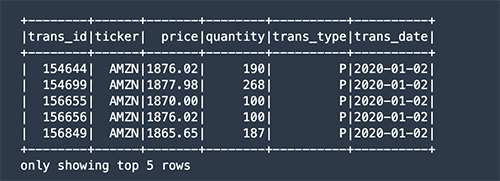
Learn how how the company simplified the way different personas in the organization query and analyze data by building a self-service data orchestration platform. The platform architecture is entirely serverless, which simplifies the ability to scale and adopt to unpredictable demand. The platform was built using AWS Step Functions, AWS Lambda, Amazon API Gateway, Amazon DynamoDB, AWS Fargate, and other AWS Serverless managed services.
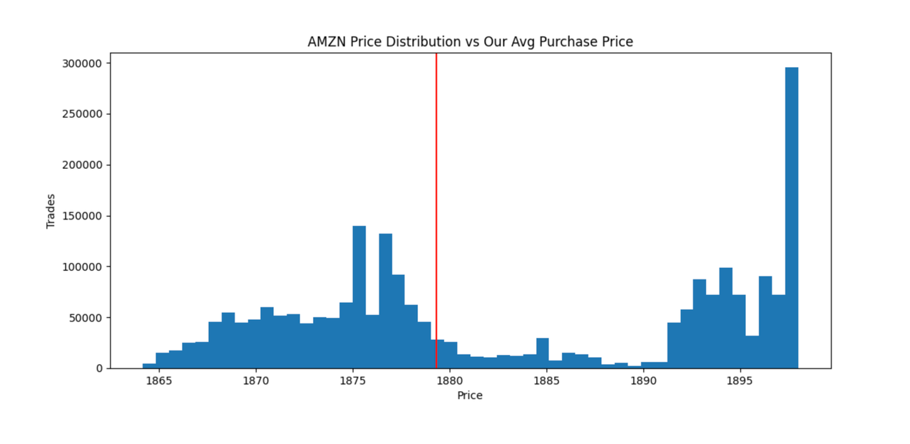
For more content like this, subscribe to our YouTube channels This is My Architecture, This is My Code, and This is My Model, or visit the This is My Architecture on AWS, which has search functionality and the ability to filter by industry, language, and service.