Post Syndicated from Rafael Ramos original https://aws.amazon.com/blogs/devops/building-a-centralized-codeguru-profiler-dashboard-multi-account/
Amazon CodeGuru is a machine learning service for development teams who want to automate code reviews, identify the most expensive lines of code in their applications, and receive intelligent recommendations on how to fix or improve their code. CodeGuru has two components: CodeGuru Profiler and CodeGuru Reviewer.
CodeGuru Profiler searches for application performance optimizations and recommends ways to fix issues such as excessive recreation of expensive objects, expensive deserialization, usage of inefficient libraries, and excessive logging. CodeGuru Profiler runs continuously, consuming minimal CPU capacity so it doesn’t significantly impact application performance. You can run an agent or import libraries into your application and send the data collected to CodeGuru, and review the findings on the CodeGuru console.
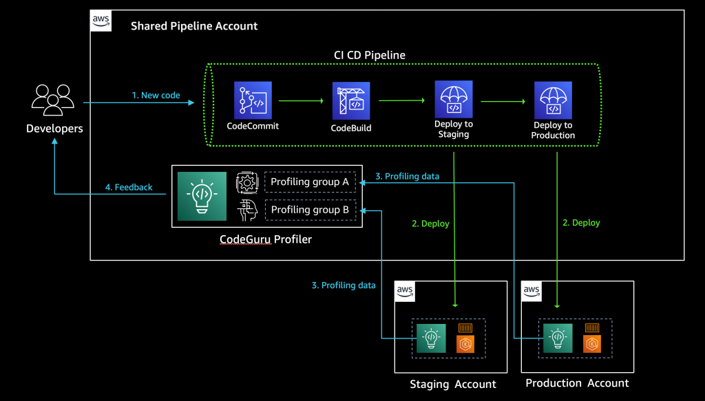
As a best practice, AWS recommends a multi-account strategy for your cloud environment. See Benefits of using multiple AWS accounts for additional details. In this scenario, your CI/CD pipeline deploys your application on the multiple software development lifecycle (SDLC) and production accounts. As a consequence, you’d have one CodeGuru Profiler dashboard per account, which makes it hard for developers to analyze the applications’ performance. This post shows you how to configure CodeGuru Profiler to collect multiple applications’ profiling data into a central account and review the applications’ performance data on one dashboard.
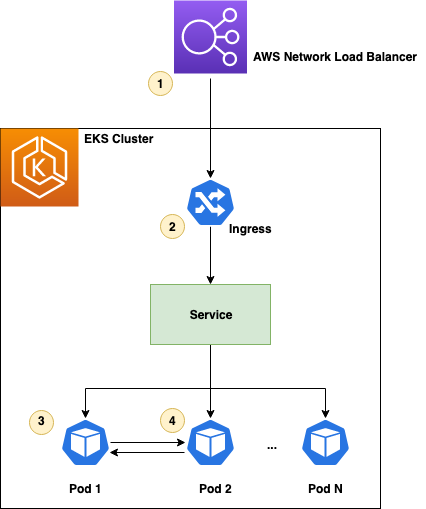
See the diagram below for a typical CI/CD pipeline on multi-account environment, and a central CodeGuru Profiler dashboard:
Solution overview
The benefits of sending CodeGuru profiling data to a central AWS account within the same region is that it gives you a single pane of glass to review all of CodeGuru Profiler’s findings and recommendations in one place. At the time of this writing, we don’t recommend sending CodeGuru profiling data across regions. Additionally, we show you how to configure the AWS Identity and Access Management (IAM) roles to assume a cross-account role when running pods on Amazon Elastic Kubernetes Service (Amazon EKS) with OpenID Connect (OIDC), as well as how to configure IAM roles to allow access when using other resources, such as Amazon Elastic Compute Cloud (EC2). On this solution we discuss how to enable the CodeGuru agent within your code, but it’s also possible enable the agent with no code changes. For more information, see Enable the agent from the command line.
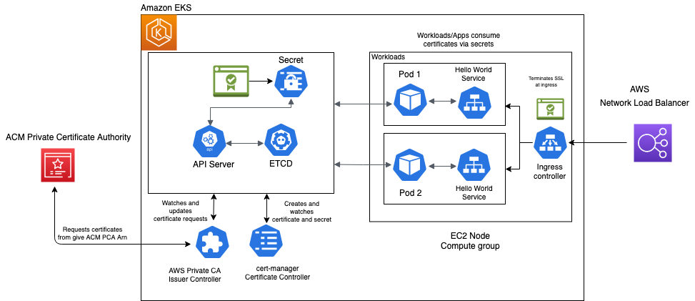
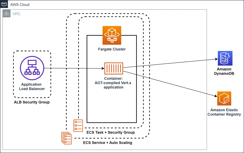
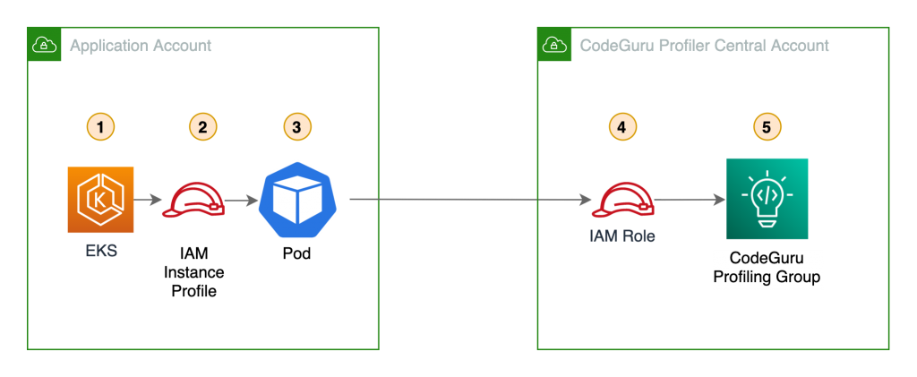
The following diagram illustrates our architecture.
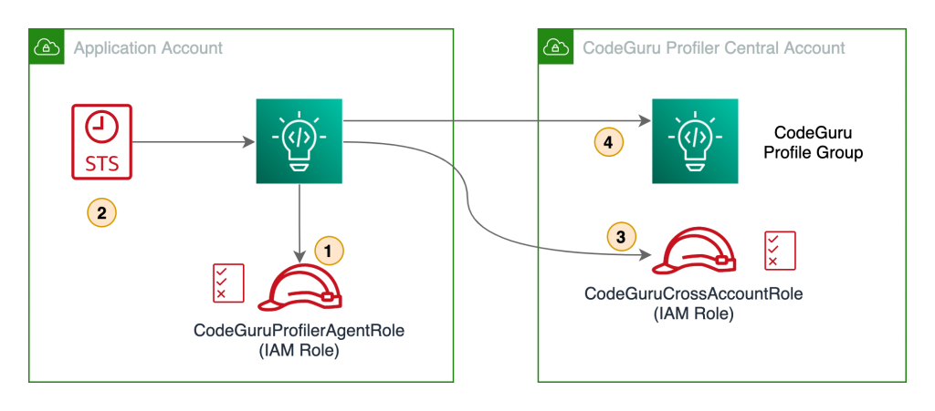
Our solution has the following components:
- The application in the application account assumes the
CodeGuruProfilerAgentRoleIAM role. This IAM role has a policy that allows the application to assume the role in the CodeGuru Profiler central account. - AWS Security Token Service (AWS STS) returns temporary credentials required to assume the IAM role in the central account.
- The application assumes the
CodeGuruCrossAccountRoleIAM role in the central account. - The application using the
CodeGuruCrossAccountRolerole sends CodeGuru Profiler data to the central account.
Prerequisites
Before getting started, you must have the following requirements:
- Two AWS accounts:
- Central account – Where the single pane of glass to review all of CodeGuru Profiler’s findings and recommendations resides. The applications from all the other AWS accounts send profiling data to CodeGuru Profiler in the central account.
- Application account – The dedicated account where the profiled application resides.
- Install and authenticate the AWS Command Line Interface (AWS CLI). You can authenticate with an IAM user or AWS STS token.
- If you’re using Amazon EKS, you need the following installed:
Walkthrough overview
At the time of this writing, CodeGuru supports two programming languages: Python and Java. Each language has a different configuration for sending CodeGuru profiling data to a different AWS account.
Let’s consider a use case where we have two applications that we want to configure to send CodeGuru profiling data to a centralized account. The first application is running Python 3.x and the other application is running Java on JRE 1.8. We need to configure two IAM roles, one in the application account and one in the central account.
We complete the following steps:
- Configure the IAM roles and policies.
- Configure the CodeGuru profiling groups.
- Configure your Java application to send profiling data to the central account.
- Configure your Python application to send profiling data to the central account.
- Configure IAM with Amazon EKS.
- Review findings and recommendations on the CodeGuru Profiler dashboard.
Configuring IAM roles and policies
To allow a CodeGuru Profiler agent on the application account to send profiling information to CodeGuru Profiler on the central account, we need to create a cross-account IAM role in the central account that the CodeGuru Profiler agent can assume. We also need to attach a policy with the necessary privileges to the cross-account role, and configure a role in the application account to allow assuming the cross-account role in the central account.
First, we must configure a cross-account IAM role in the central account that the CodeGuru Profiler agent in the application account assumes. We can create a role called CodeGuruCrossAccountRole on the central account, and assign the IAM trusted entity to allow the CodeGuru Profiler agent to assume the role from the application account. For more information, see IAM tutorial: Delegate access across AWS accounts using IAM roles. The CodeGuruCrossAccountRole trust relationship should look like the following code:
{
  "Version": "2012-10-17",
  "Statement": [
    {
      "Effect": "Allow",
      "Principal": {
        "AWS": "arn:aws:iam::<APPLICATION_ACCOUNT_ID>:role/<CODEGURU_PROFILER_AGENT_ROLE_NAME>"
      },
      "Action": "sts:AssumeRole"
    }
  ]
}
After that, we need to attach an AWS managed policy called AmazonCodeGuruProfilerAgentAccess to the CodeGuruCrossAccountRole role. It allows the CodeGuru Profiler agent to send data to the two profiling groups we configure in the next step. For more fine-grained access control, you can create your own IAM policy to allow sending data only to the two specific profiling groups we create. The following code is an example IAM policy that allows a CodeGuru Profiler agent to send profiler data to two profiling groups:
{
  "Version": "2012-10-17",
  "Statement": [{
    "Effect": "Allow",
    "Action": [
      "codeguru-profiler:ConfigureAgent",
      "codeguru-profiler:PostAgentProfile"
    ],
    "Resource": [
        "arn:aws:codeguru-profiler:eu-west-1:<CODEGURU_CENTRAL_ACCOUNT_ID>:profilingGroup/
        JavaAppProfilingGroup",
        "arn:aws:codeguru-profiler:eu-west-1:<CODEGURU_CENTRAL_ACCOUNT_ID>:profilingGroup/
        PythonAppProfilingGroup"
    ]
  }]
}
Here are the IAM policy actions that CodeGuru Profiler requires:
codeguru-profiler:ConfigureAgentgrants permission for an agent to register with the orchestration service and retrieve profiling configuration information.codeguru-profiler:PostAgentProfilegrants permission to submit a profile collected by an agent belonging to a specific profiling group for aggregation.
Last, we need to configure the CodeGuruProfilerAgentRole IAM role in the application account with an IAM policy that allows the application to assume the role in the central account:
{
  "Version": "2012-10-17",
  "Statement": [{
    "Effect": "Allow",
    "Action": "sts:AssumeRole",
    "Resource": "arn:aws:iam::<CODEGURU_CENTRAL_ACCOUNT_ID>:role/CodeGuruCrossAccountRole
  }]
}
To apply this IAM policy to the CodeGuruProfilerAgentRole IAM role, the IAM role needs to be created depending on the platform you are running, such as Amazon Elastic Compute Cloud (Amazon EC2), AWS Lambda, or Amazon EKS. In this post, we discuss how to configure IAM roles for Amazon EKS. For information about IAM roles for Amazon EC2 and Lambda, see IAM roles for Amazon EC2 and AWS Lambda execution role, respectively.
Configuring the CodeGuru profiling groups
Now we need to create two CodeGuru profiling groups on the central account: one for our Java application and one for our Python application. For this post, we just demonstrate the steps for configuring the Python application.
- On the CodeGuru console, under Profiler, choose Profiling groups.
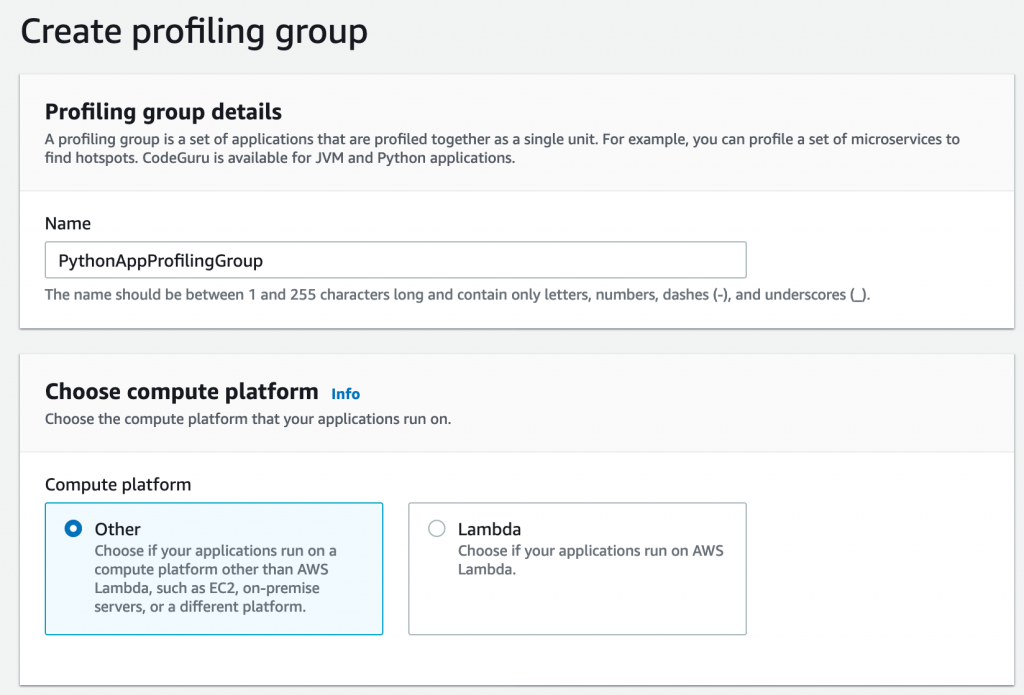
- Choose Create profiling group.
- For Name, enter a name (for this post, we use PythonAppProfilingGroup).
- For Compute platform, select Other.
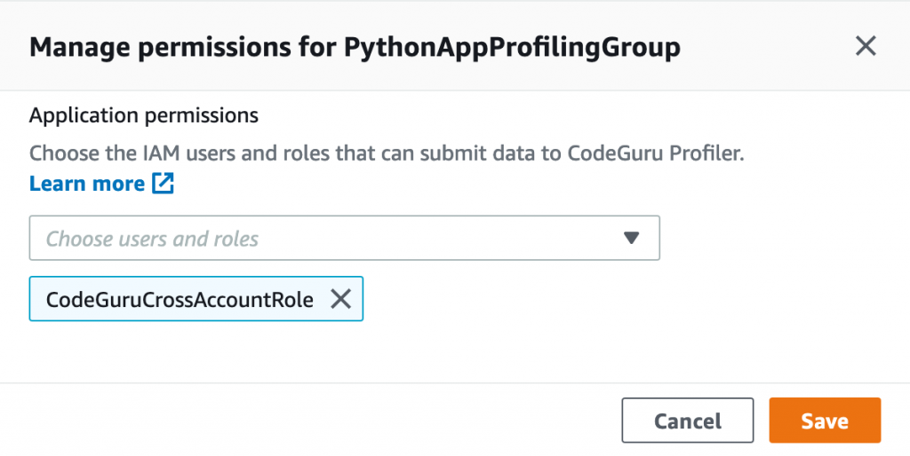
After you create your profiling group, you need to provide some additional settings.
- Select the profiling group you created.
- On the Actions menu, choose Manage permissions.
- Choose the IAM role
CodeGuruCrossAccountRoleyou created before. - Choose Save.
When you complete the configuration, the status of the profiling group shows as Setup required. This is because we need to configure the CodeGuru profiling agent to send data to the profiling group. We cover how to do this for both the Java and Python agent in the next section.
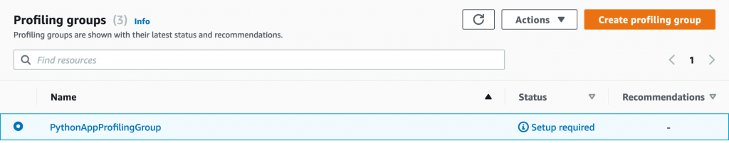
After we configure the agent, we see the status change from Pending to Profiling approximately 15 minutes after CodeGuru Profiler starts sending data.
Configuring your Java application to send profiling data to the central account
To send CodeGuru profiling data to a centralized account when running the agent within the application code, we need to import the CodeGuru agent JAR file into your Java application.
For more information on how to enable the agent, see Enabling the agent with code.
The following table shows the Java types and API calls for each type.
| Type | API call |
| Profiling group name (required) | .profilingGroupName(String) |
| AWS Credentials Provider | .awsCredentialsProvider(AwsCredentialsProvider) |
| Region (optional) | .awsRegionToReportTo(Region) |
| Heap summary data collection (optional) | .withHeapSummary(Boolean) |
As part of the CodeGuru Profiler.Builder class, we have an option to provide an AWS credentials provider type, which also includes an AWS role ARN, as follows:
import software.amazon.codeguruprofilerjavaagent.Profiler;
...

class MyApplication{

    static String roleArn =
        "arn:aws:iam::<CODEGURU_CENTRAL_ACCOUNT_ID>:role/CodeGuruCrossAccountRole";
    static String sessionName = "codeguru-java-session";

    public static void main(String[] args) {
        ...
        Profiler.builder()
            .profilingGroupName("JavaAppProfilingGroup")
            .awsCredentialsProvider(AwsCredsProvider.getCredentials(
                                        roleArn,
                                        sessionName))
            .withHeapSummary(true)
            .build()
            .start();
        ...
    }
}
The awsCredentialsProvider API call allows you to provide an interface for loading AwsCredentials that are used for authentication. For this post, I create an AwsCredsProvider class with the getCredentials method.
The following code shows the AwsCredsProvider class in more detail:
import software.amazon.awssdk.auth.credentials.AwsCredentialsProvider;
import software.amazon.awssdk.auth.credentials.DefaultCredentialsProvider;
import software.amazon.awssdk.services.sts.StsClient;
import software.amazon.awssdk.services.sts.auth.StsAssumeRoleCredentialsProvider;
import software.amazon.awssdk.services.sts.model.AssumeRoleRequest;


public class AwsCredsProvider {

    public static AwsCredentialsProvider getCredentials(
                                            String roleArn,
                                            String sessionName){

        final AssumeRoleRequest assumeRoleRequest = AssumeRoleRequest.builder()
                .roleArn(roleArn)
                .roleSessionName(sessionName)
                .build();


        return StsAssumeRoleCredentialsProvider
                .builder()
                        .stsClient(StsClient.builder()
                        .credentialsProvider(DefaultCredentialsProvider.create())
                        .build())
                .refreshRequest(assumeRoleRequest)
                .build();
    }
}
Configuring your Python application to send profiling data to the central account
You can run the CodeGuru Profiler library in your Python codebase by installing the CodeGuru agent using pip install codeguru_profiler_agent.
You can configure the agent by passing different parameters to the Profiler object, as summarized in the following table.
| Option | Constructor Argument |
| Profiling group name (required) | profiling_group_name="MyProfilingGroup" |
| Region | region_name="eu-west-2" |
| AWS session | aws_session=boto3.session.Session() |
We use the same concepts as with the Java app to assume a role in the CodeGuru central account. The following Python snippet shows you how to instantiate the CodeGuru Profiler object:
import boto3
from codeguru_profiler_agent import Profiler

def assume_role(iam_role):

    sts_client = boto3.client('sts')
    assumed_role = sts_client.assume_role(RoleArn =  iam_role,
                                      RoleSessionName = "codeguru-python-session",
                                      DurationSeconds = 900)

    codeguru_session = boto3.Session(
        aws_access_key_id     = assumed_role['Credentials']['AccessKeyId'],
        aws_secret_access_key = assumed_role['Credentials']['SecretAccessKey'],
        aws_session_token     = assumed_role['Credentials']['SessionToken']
    )

    return codeguru_session


if __name__ == "__main__":

    iam_role = "arn:aws:iam::<CODEGURU_CENTRAL_ACCOUNT_ID>:role/CodeGuruCrossAccountRole"
    codeguru_session = assume_role(iam_role)
    Profiler(profiling_group_name="PythonAppProfilingGroup",
             region_name="<YOUR REGION>",
             aws_session=codeguru_session).start()
    ...
Configuring IAM with Amazon EKS
You can use two different methods to configure the IAM role to allow the CodeGuru Profiler agent to send data from the application account to the CodeGuru Profiler central account:
- Associate an IAM role with a Kubernetes service account; this account can then provide AWS permissions to the containers in any pod that uses that service account
- Provide an IAM instance profile to the EKS node so that all pods running on this node have access to this role
For more information about configuring either option, see Enabling cross-account access to Amazon EKS cluster resources.
You can use the same CodeGuru codebase to assume a role by either using an IAM role for service accounts or an adding IAM instance profile to an EKS node.
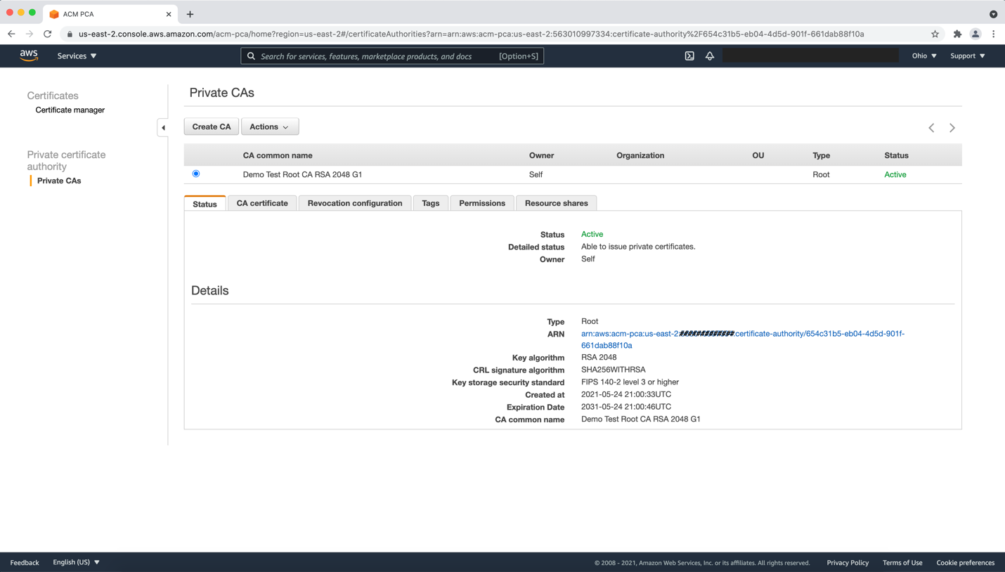
The following diagram shows our architecture for a cross-account profiler using IAM roles for service accounts.
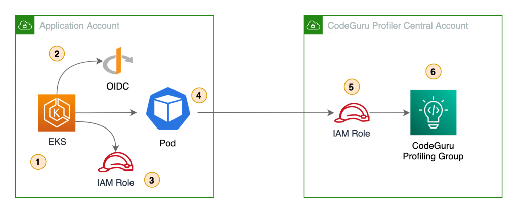
In this architecture, the pods use Amazon web identity to get credentials for the IAM role assigned to the pod via the Kubernetes service account. This role needs permission to assume the IAM role in the CodeGuru central account.
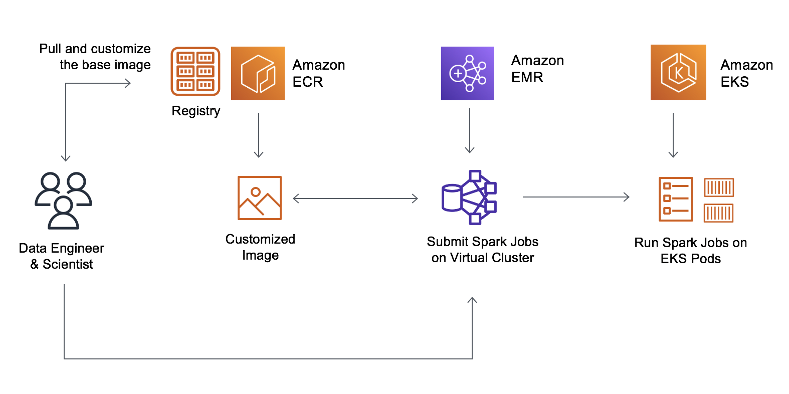
The following diagram shows the architecture of a cross-account profiler using an EKS node IAM instance profile.
In this scenario, the pods use the IAM role assigned to the EKS node. This role needs permission to assume the IAM role in the central account.
In either case, the code doesn’t change and you can assume the IAM role in the central account.
Reviewing findings and recommendations on the CodeGuru Profiler dashboard
Approximately 15 minutes after the CodeGuru Profiler agent starts sending application data to the profiler on the central account, the profiling group changes its status to Profiling. You can visualize the application performance data on the central account’s CodeGuru Profiler dashboard.
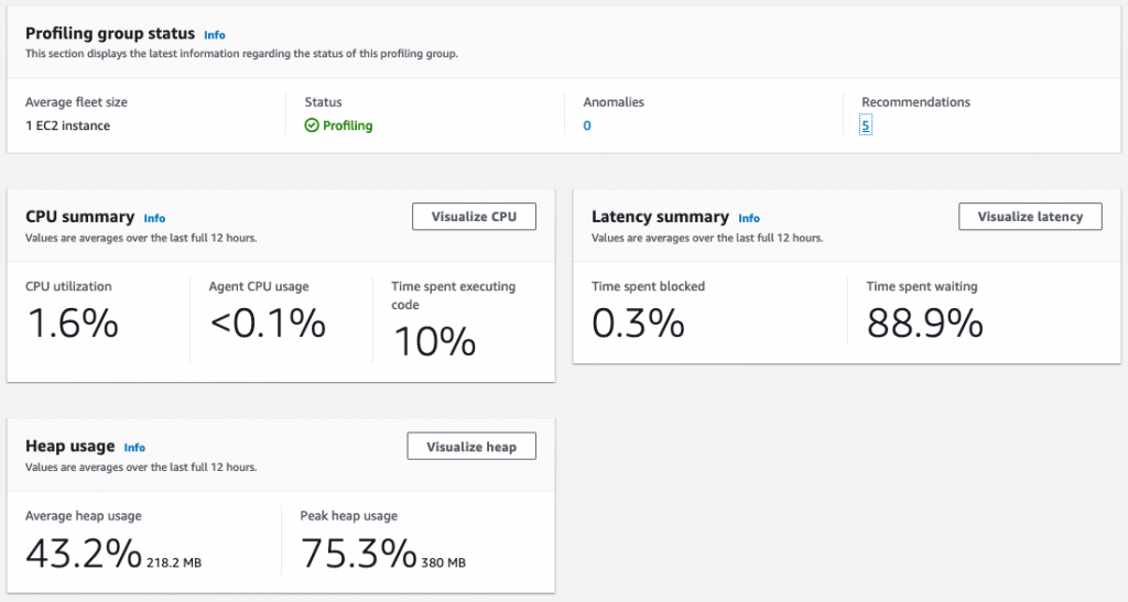
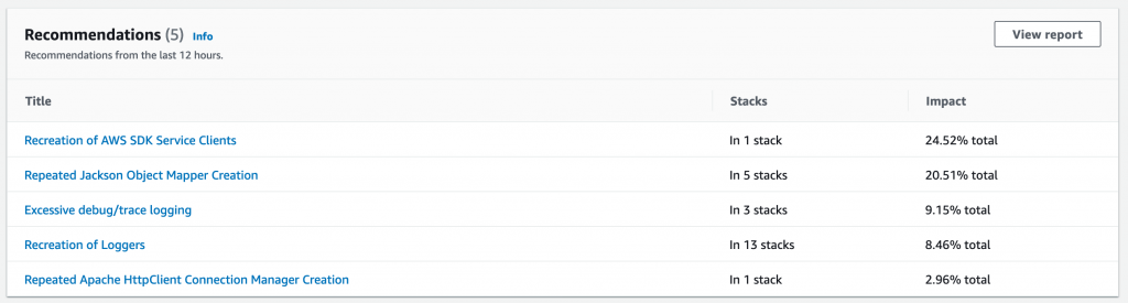
In addition, the dashboard provides recommendations on how to improve your application performance based on the data the agent is collecting.
Conclusion
In this post, you learned how to configure CodeGuru Profiler to collect multiple applications’ profiling data into a central account. This approach makes profiling dashboards more accessible on multi-account setups, and facilitates how developers can analyze the behavior of their distributed workloads. Moreover, because developers only need access to the central account, you can follow the least privilege best practice and isolate the other accounts.
You also learned how to initiate the CodeGuru Profiler agent from both Python and Java applications using cross-account IAM roles, as well as how to use IAM roles for service accounts on Amazon EKS for fine-grained access control and enhanced security. Although CodeGuru Profiler supports Lambda functions profiling, at the time of this writing, it’s only possible to send profiling data to the same AWS account where the Lambda function runs.
For more details regarding how CodeGuru Profiler can help improve application performance, see Optimizing application performance with Amazon CodeGuru Profiler.

Oli Leach
Oli is a Global Solutions Architect at Amazon Web Services, and works with Financial Services customers to help them architect, build, and scale applications to achieve their business goals.

Rafael Ramos
Rafael is a Solutions Architect at AWS, where he helps ISVs on their journey to the cloud. He spent over 13 years working as a software developer, and is passionate about DevOps and serverless. Outside of work, he enjoys playing tabletop RPG, cooking and running marathons.