Tag Archives: Analytics

Run a Spark SQL-based ETL pipeline with Amazon EMR on Amazon EKS

Post Syndicated from Melody Yang original https://aws.amazon.com/blogs/big-data/run-a-spark-sql-based-etl-pipeline-with-amazon-emr-on-amazon-eks/

This blog post has been translated into the following languages:

Increasingly, a business’s success depends on its agility in transforming data into actionable insights, which requires efficient and automated data processes. In the previous post – Build a SQL-based ETL pipeline with Apache Spark on Amazon EKS, we described a common productivity issue in a modern data architecture. To address the challenge, we demonstrated how to utilize a declarative approach as the key enabler to improve efficiency, which resulted in a faster time to value for businesses.

Generally speaking, managing applications declaratively in Kubernetes is a widely adopted best practice. You can use the same approach to build and deploy Spark applications with open-source or in-house build frameworks to achieve the same productivity goal.

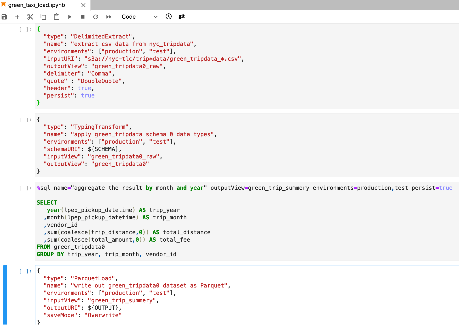
For this post, we use the open-source data processing framework Arc, which is abstracted away from Apache Spark, to transform a regular data pipeline to an “extract, transform, and load (ETL) as definition” job. The steps in the data pipeline are simply expressed in a declarative definition (JSON) file with embedded declarative language SQL scripts.

The job definition in an Arc Jupyter notebook looks like the following screenshot.

This representation makes ETL much easier for a wider range of personas: analysts, data scientists, and any SQL authors who can fully express their data workflows without the need to write code in a programming language like Python.

In this post, we explore some key advantages of the latest Amazon EMR deployment option Amazon EMR on Amazon EKS to run Spark applications. We also explain its major difference from the commonly used Spark resource manager YARN, and demonstrate how to schedule a declarative ETL job with EMR on EKS. Building and testing the job on a custom Arc Jupyter kernel is out of scope for this post. You can find more tutorials on the Arc website.

Why choose Amazon EMR on Amazon EKS?

The following are some of the benefits of EMR on EKS:

  • Simplified architecture by unifying workloads – EMR on EKS enables us to run Apache Spark workloads on Amazon Elastic Kubernetes Service (Amazon EKS) without provisioning dedicated EMR clusters. If you have an existing Amazon EKS landscape in your organization, it makes sense to unify analytical workloads with other Kubernetes-based applications on the same Amazon EKS cluster. It improves resource utilization and significantly simplifies your infrastructure management.
  • More resources to share with a smaller JVM footprint – A major difference in this deployment option is the resource manager shift from YARN to Kubernetes and from a Hadoop cluster manager to a generic containerized application orchestrator. As shown in the following diagram, each Spark executor runs as a YARN container (compute and memory unit) in Hadoop. Broadly, YARN creates a JVM in each container requested by Hadoop applications, such as Apache Hive. When you run Spark on Kubernetes, it keeps your JVM footprint minimal, so that the Amazon EKS cluster can accommodate more applications, resulting in more spare resources for your analytical workloads.

  • Efficient resource sharing and cost savings – With the YARN cluster manager, if you want to reuse the same EMR cluster for concurrent Spark jobs to reduce cost, you have to compromise on resource isolation. Additionally, you have to pay for compute resources that aren’t fully utilized, such as a master node, because only Amazon EMR can use these unused compute resources. With EMR on EKS, you can enjoy the optimized resource allocation feature by sharing them across all your applications, which reduces cost.
  • Faster EMR runtime for Apache Spark – One of the key benefits of running Spark with EMR on EKS is the faster EMR runtime for Apache Spark. The runtime is a performance-optimized environment, which is available and turned on by default on Amazon EMR release 5.28.0 and later. In our performance tests using TPC-DS benchmark queries at 3 TB scale, we found EMR runtime for Apache Spark 3.0 provides a 1.7 times performance improvement on average, and up to 8 times improved performance for individual queries over open-source Apache Spark 3.0.0. It means you can run your Apache Spark applications faster and cheaper without requiring any changes to your applications.
  • Minimum setup to support multi-tenancy – While taking advantage of Spark’s Dynamic Resource Allocation, auto scaling in Amazon EKS, high availability with multiple Availability Zones, you can isolate your workloads for multi-tenancy use cases, with a minimum configuration required. Additionally, without any infrastructure setup, you can use an Amazon EKS cluster to run a single application that requires different Apache Spark versions and configurations, for example for development vs test environments.

Cost effectiveness

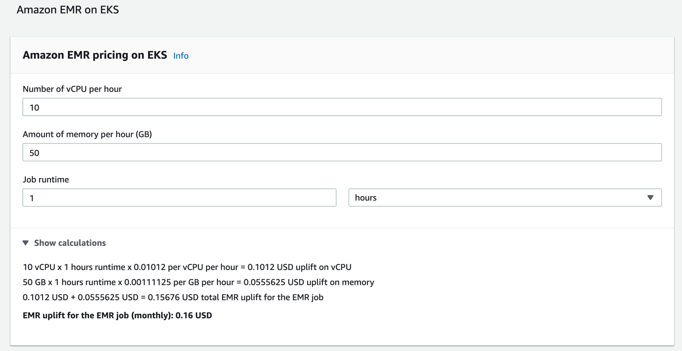
EMR on EKS pricing is calculated based on the vCPU and memory resources used from the time you start to download your Amazon EMR application image until the Spark pod on Amazon EKS stops, rounded up to the nearest second. The following screenshot is an example of the cost in the us-east-1 Region.

The Amazon EMR uplift price is in addition to the Amazon EKS pricing and any other services used by Amazon EKS, such as EC2 instances and EBS volumes. You pay $0.10 per hour for each Amazon EKS cluster that you use. However, you can use a single Amazon EKS cluster to run multiple applications by taking advantage of Kubernetes namespaces and AWS Identity and Access Management (IAM) security policies.

While the application runs, your resources are allocated and removed automatically by the Amazon EKS auto scaling feature, in order to eliminate over-provisioning or under-utilization of these resources. It enables you to lower costs because you only pay for the resources you use.

To further reduce the running cost for jobs that aren’t time-critical, you can schedule Spark executors on Spot Instances to save up to 90% over On-Demand prices. In order to maintain the resiliency of your Spark cluster, it is recommended to run driver on a reliable On-Demand Instance, because the driver is responsible for requesting new executors to replace failed ones when an unexpected event happens.

Kubernetes comes with a YAML specification called a pod template that can help you to assign Spark driver and executor pods to Spot or On-Demand EC2 instances. You define nodeSelector rules in pod templates, then upload to Amazon Simple Storage Service (Amazon S3). Finally, at the job submission, specify the Spark properties spark.kubernetes.driver.podTemplateFile and spark.kubernetes.executor.podTemplateFile to point to the pod templates in Amazon S3.

For example, the following is the code for executor_pod_template.yaml:

apiVersion: v1
kind: Pod
spec:
  nodeSelector:
    eks.amazonaws.com/capacityType: SPOT

The following is the code for driver_pod_template.yaml:

apiVersion: v1
kind: Pod
spec:
  nodeSelector:
    eks.amazonaws.com/capacityType: ON_DEMAND

The following is the code for the Spark job submission:

aws emr-containers start-job-run \
--virtual-cluster-id ${EMR_EKS_CLUSTER_ID} \
--name spark-pi-pod-template \
--execution-role-arn ${EMR_EKS_ROLE_ARN} \
--release-label emr-5.33.0-latest \
--job-driver '{
    "sparkSubmitJobDriver": {
        "entryPoint": "s3://'${s3DemoBucket}'/someAppCode.py",
        "sparkSubmitParameters": "--conf spark.kubernetes.driver.podTemplateFile=\"s3://'${s3DemoBucket}'/pod_templates/driver_pod_template.yaml\" --conf spark.kubernetes.executor.podTemplateFile=\"s3://'${s3DemoBucket}'/pod_templates/executor_pod_template.yaml\" --conf spark.executor.instances=2 --conf spark.executor.memory=2G --conf spark.executor.cores=2"
	}
    }'

Beginning with Amazon EMR versions 5.33.0 or 6.3.0, Amazon EMR on EKS supports the Amazon S3-based pod template feature. If you’re using an unsupported Amazon EMR version, such as EMR 6.1.0, you can use the pod template feature without Amazon S3 support. Make sure your Spark version is 3.0 or later, and copy the template files into your custom Docker image. The job submit script is changed to the following:

"--conf spark.kubernetes.driver.podTemplateFile=/local/path/to/driver_pod_template.yaml" 
"--conf spark.kubernetes.executor.podTemplateFile=/local/path/to/executor_pod_template.yaml"

Serverless compute option: AWS Fargate

The sample solution runs on an Amazon EKS cluster with AWS Fargate. Fargate is a serverless compute engine for Amazon EKS and Amazon ECS. It makes it easy for you to focus on building applications because it removes the need to provision and manage EC2 instances or managed node groups in EKS. Fargate runs each task or pod in its own kernel, providing its own isolated compute environment. This enables your application to have resource isolation and enhanced security by design.

With Fargate, you don’t need to be an expert in Kubernetes operations. It automatically allocates the right amount of compute, eliminating the need to choose instances and scale cluster capacity, so the Kubernetes Cluster Autoscaler is no longer required to increase your cluster’s compute capacity.

In our instance, each Spark executor or driver is provisioned by a separate Fargate pod, to form a Spark cluster dedicated to an ETL pipeline. You only need to specify and pay for resources required to run the application—no more concerns about complex cluster management, queues, and isolation trade-offs.

Other Amazon EC2 options

In addition to the serverless choice, EMR on EKS can operate on all types of EKS clusters. For example, Amazon EKS managed node groups with Amazon Elastic Compute Cloud (Amazon EC2) On-Demand and Spot Instances.

Previously, we mentioned placing a Spark driver pod on an On-Demand Instance to reduce interruption risk. To further improve your cluster stability, it’s important to understand the Kubernetes high availability and restart policy features. These allow for exciting new possibilities, not only in computational multi-tenancy, but also in the ability of application self-recovery, for example relaunching a Spark driver on Spot or On-Demand instances. For more information and an example, see the GitHub repo.

As of this writing, our test result shows that a Spark driver can’t restart on failure with the EMR on EKS deployment type. So be mindful when designing a Spark application with the minimum downtime need, especially for a time-critical job. We recommend the following:

  • Diversify your Spot requests – Similar to Amazon EMR’s instance fleet, EMR on EKS allows you to deploy a single application across multiple instance types to further enhance availability. With Amazon EC2 Spot best practices, such as capacity rebalancing, you can diversify the Spot request across multiple instance types within each Availability Zone. It limits the impact of Spot interruptions on your workload, if a Spot Instance is reclaimed by Amazon EC2. For more details, see Running cost optimized Spark workloads on Kubernetes using EC2 Spot Instances.
  • Increase resilience – Repeatedly restarting a Spark application compromises your application performance or the length of your jobs, especially for time-sensitive data processes. We recommend the following best practice to increase your application resilience:
    • Ensure your job is stateless so that it can self-recover without waiting for a dependency.
    • If a checkpoint is required, for example in a stateful Spark streaming ETL, make sure your checkpoint storage is decoupled from the Amazon EKS compute resource, which can be detached and attached to your Kubernetes cluster via the persistent volume claims (PVCs), or simply use S3 Cloud Storage.
    • Run the Spark driver on the On-Demand Instance defined by a pod template. It adds an extra layer of resiliency to your Spark application with EMR on EKS.

Security

EMR on EKS inherits the fine-grained security feature IAM roles for service accounts, (IRSA), offered by Amazon EKS. This means your data access control is no longer at the compute instance level, instead it’s granular at the container or pod level and controlled by an IAM role. The token-based authentication approach allows us to use one of the AWS default credential providers WebIdentityTokenCredentialsProvider to exchange the Kubernetes-issued token for IAM role credentials. It makes sure our applications deployed with EMR on EKS can communicate to other AWS services in a secure and private channel, without the need to store a long-lived AWS credential pair as a Kubernetes secret.

To learn more about the implementation details, see the GitHub repo.

Solution overview

In this example, we introduce a quality-aware design with the open-source declarative data processing Arc framework to abstract Spark technology away from you. It makes it easy for you to focus on business outcomes, not technologies.

We walk through the steps to run a predefined Arc ETL job with the EMR on EKS approach. For more information, see the GitHub repo.

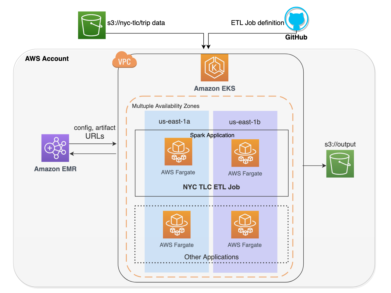
The sample solution launches a serverless Amazon EKS cluster, loads TLC green taxi trip records from a public S3 bucket, applies dataset schema, aggregates the data, and outputs to an S3 bucket as Parquet file format. The sample Spark application is defined as a Jupyter notebook green_taxi_load.ipynb powered by Arc, and the metadata information is defined in green_taxi_schema.json.

The following diagram illustrates our solution architecture.

Launch Amazon EKS

Provisioning takes approximately 20 minutes.

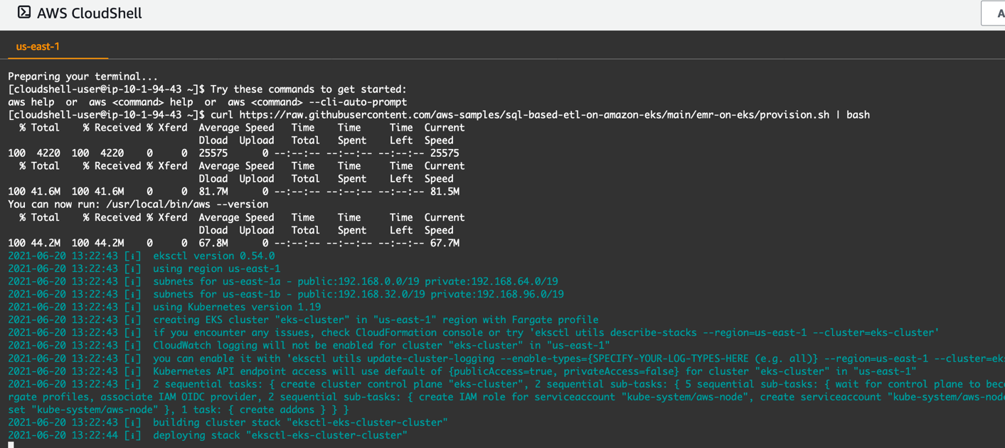
To get started, open AWS CloudShell in the us-east-1 Region. Run the following command to provision the new cluster eks-cluster, backed by Fargate. Then build the EMR virtual cluster emr-on-eks-cluster:

curl https://raw.githubusercontent.com/aws-samples/sql-based-etl-on-amazon-eks/main/emr-on-eks/provision.sh | bash

At the end of the provisioning, the shell script automatically creates an EMR virtual cluster by the following command. It registers Amazon EMR with the newly created Amazon EKS cluster. The dedicated namespace on the EKS is called emr.

Deploy the sample ETL job

  1. When provisioning is complete, submit the sample ETL job to EMR on EKS with a serverless virtual cluster called emr-on-eks-cluster:
curl https://raw.githubusercontent.com/aws-samples/sql-based-etl-on-amazon-eks/main/emr-on-eks/submit_arc_job.sh | bash

It runs the following job summit command:

The declarative ETL job can be found on the blogpost’s GitHub repository. This is a screenshot of the job specification:

  1. Check your job progress and auto scaling status:
kubectl get pod -n emr
kubectl get node --label-columns=topology.kubernetes.io/zone
  1. As the job requested 10 executors, it automatically scales the Spark application from 0 to 10 pods (executors) on the EKS cluster. The Spark application automatically removes itself from the EKS when the job is done.

  1. Navigate to your Amazon EMR console to view application logs on the Spark History Server.

  1. You can also check the logs in CloudShell, as long as your Spark Driver is running:
driver_name=$(kubectl get pod -n emr | grep "driver" | awk '{print $1}')
kubectl logs ${driver_name} -n emr -c spark-kubernetes-driver | grep 'event'

Clean up

To clean up the AWS resources you created, run the following code:

curl https://raw.githubusercontent.com/aws-samples/sql-based-etl-on-amazon-eks/main/emr-on-eks/deprovision.sh | bash

Region support

At the time of this writing, Amazon EMR on EKS is available in US East (N. Virginia), US West (Oregon), US West (N. California), US East (Ohio), Canada (Central), Europe (Ireland, Frankfurt, and London), and Asia Pacific (Mumbai, Seoul, Singapore, Sydney, and Tokyo) Regions. If you want to use EMR on EKS in a Region that isn’t available yet, check out the open-source Apache Spark on Amazon EKS alternative on aws-samples GitHub. You can deploy the sample solution to your Region as long as Amazon EKS is available. Migrating a Spark workload on Amazon EKS to the fully managed EMR on EKS is easy and straightforward, with minimum changes required. Because the self-contained Spark application remains the same, only the deployment implementation differs.

Conclusion

This post introduces Amazon EMR on Amazon EKS and provides a walkthrough of a sample solution to demonstrate the “ETL as definition” concept. A declarative data processing framework enables you to build and deploy your Spark workloads with enhanced efficiency. With EMR on EKS, running applications built upon a declarative framework maximizes data process productivity, performance, reliability, and availability at scale. This pattern abstracts Spark technology away from you, and helps you to focus on deliverables that optimize business outcomes.

The built-in optimizations provided by the managed EMR on EKS can help not only data engineers with analytical skills, but also analysts, data scientists, and any SQL authors who can fully express their data workflows declaratively in Spark SQL. You can use this architectural pattern to drive your data ownership shift in your organization, from IT to non-IT stakeholders who have a better understanding of business operations and needs.


About the Authors

Melody Yang is a Senior Analytics Specialist Solution Architect at AWS with expertise in Big Data technologies. She is an experienced analytics leader working with AWS customers to provide best practice guidance and technical advice in order to assist their success in data transformation. Her areas of interests are open-source frameworks and automation, data engineering and DataOps.


Shiva Achari is a Senior Data Lab Architect at AWS. He helps AWS customers to design and build data and analytics prototypes via the AWS Data Lab engagement. He has over 14 years of experience working with enterprise customers and startups primarily in the Data and Big Data Analytics space.


Daniel Maldonado is an AWS Solutions Architect, specialist in Microsoft workloads and Big Data technologies, focused on helping customers to migrate their applications and data to AWS. Daniel has over 12 years of experience working with Information Technologies and enjoys helping clients reap the benefits of running their workloads in the cloud.


Igor Izotov is an AWS enterprise solutions architect, and he works closely with Australia’s largest financial services organizations. Prior to AWS, Igor held solution architecture and engineering roles with tier-1 consultancies and software vendors. Igor is passionate about all things data and modern software engineering. Outside of work, he enjoys writing and performing music, a good audiobook, or a jog, often combining the latter two.

How to Accelerate Building a Lake House Architecture with AWS Glue

Post Syndicated from Raghavarao Sodabathina original https://aws.amazon.com/blogs/architecture/how-to-accelerate-building-a-lake-house-architecture-with-aws-glue/

Customers are building databases, data warehouses, and data lake solutions in isolation from each other, each having its own separate data ingestion, storage, management, and governance layers. Often these disjointed efforts to build separate data stores end up creating data silos, data integration complexities, excessive data movement, and data consistency issues. These issues are preventing customers from getting deeper insights. To overcome these issues and easily move data around, a Lake House approach on AWS was introduced.

In this blog post, we illustrate the AWS Glue integration components that you can use to accelerate building a Lake House architecture on AWS. We will also discuss how to derive persona-centric insights from your Lake House using AWS Glue.

Components of the AWS Glue integration system

AWS Glue is a serverless data integration service that facilitates the discovery, preparation, and combination of data. It can be used for analytics, machine learning, and application development. AWS Glue provides all of the capabilities needed for data integration. So you can start analyzing your data and putting it to use in minutes, rather than months.

The following diagram illustrates the various components of the AWS Glue integration system.

Figure 1. AWS Glue integration components

Figure 1. AWS Glue integration components

Connect – AWS Glue allows you to connect to various data sources anywhere

Glue connector: AWS Glue provides built-in support for the most commonly used data stores. You can use Amazon Redshift, Amazon RDS, Amazon Aurora, Microsoft SQL Server, MySQL, MongoDB, or PostgreSQL using JDBC connections. AWS Glue also allows you to use custom JDBC drivers in your extract, transform, and load (ETL) jobs. For data stores that are not natively supported such as SaaS applications, you can use connectors. You can also subscribe to several connectors offered in the AWS Marketplace.

Glue crawlers: You can use a crawler to populate the AWS Glue Data Catalog with tables. A crawler can crawl multiple data stores in a single pass. Upon completion, the crawler creates or updates one or more tables in your Data Catalog. Extract, transform, and load (ETL) jobs that you define in AWS Glue use these Data Catalog tables as sources and targets.

Catalog – AWS Glue simplifies data discovery and governance

Glue Data Catalog: The Data Catalog serves as the central metadata catalog for the entire data landscape.

Glue Schema Registry: The AWS Glue Schema Registry allows you to centrally discover, control, and evolve data stream schemas. With AWS Glue Schema Registry, you can manage and enforce schemas on your data streaming applications.

Data quality – AWS Glue helps you author and monitor data quality rules

Glue DataBrew: AWS Glue DataBrew allows data scientists and data analysts to clean and normalize data. You can use a visual interface, reducing the time it takes to prepare data by up to 80%. With Glue DataBrew, you can visualize, clean, and normalize data directly from your data lake, data warehouses, and databases.

Curate data: You can use either Glue development endpoint or AWS Glue Studio to curate your data.

AWS Glue development endpoint is an environment that you can use to develop and test your AWS Glue scripts. You can choose either Amazon SageMaker notebook or Apache Zeppelin notebook as an environment.

AWS Glue Studio is a new visual interface for AWS Glue that supports extract-transform-and-load (ETL) developers. You can author, run, and monitor AWS Glue ETL jobs. You can now use a visual interface to compose jobs that move and transform data, and run them on AWS Glue.

AWS Data Exchange makes it easy for AWS customers to securely exchange and use third-party data in AWS. This is for data providers who want to structure their data across multiple datasets or enrich their products with additional data. You can publish additional datasets to your products using the AWS Data Exchange.

Deequ is an open-source data quality library developed internally at Amazon, for data quality. It provides multiple features such as automatic constraint suggestions and verification, metrics computation, and data profiling.

Build a Lake House architecture faster, using AWS Glue

Figure 2 illustrates how you can build a Lake House using AWS Glue components.

Figure 2. Building lake house architectures with AWS Glue

Figure 2. Building Lake House architectures with AWS Glue

The architecture flow follows these general steps:

  1. Glue crawlers scan the data from various data sources and populate the Data Catalog for your Lake House.
  2. The Data Catalog serves as the central metadata catalog for the entire data landscape.
  3. Once data is cataloged, fine-grained access control is applied to the tables through AWS Lake Formation.
  4. Curate your data with business and data quality rules by using Glue Studio, Glue development endpoints, or Glue DataBrew. Place transformed data in a curated Amazon S3 for purpose built analytics downstream.
  5. Facilitate data movement with AWS Glue to and from your data lake, databases, and data warehouse by using Glue connections. Use AWS Glue Elastic views to replicate the data across the Lake House.

Derive persona-centric insights from your Lake House using AWS Glue

Many organizations want to gather observations from increasingly larger volumes of acquired data. These insights help them make data-driven decisions with speed and agility. They must use a central data lake, a ring of purpose-built data services, and data warehouses based on persona or job function.

Figure 3 illustrates the Lake House inside-out data movement with AWS Glue DataBrew, Amazon Athena, Amazon Redshift, and Amazon QuickSight to perform persona-centric data analytics.

Figure 3. Lake house persona-centric data analytics using AWS Glue

Figure 3. Lake House persona-centric data analytics using AWS Glue

This shows how Lake House components serve various personas in an organization:

  1. Data ingestion: Data is ingested to Amazon Simple Storage Service (S3) from different sources.
  2. Data processing: Data curators and data scientists use DataBrew to validate, clean, and enrich the data. Amazon Athena is also used to run improvised queries to analyze the data in the lake. The transformation is shared with data engineers to set up batch processing.
  3. Batch data processing: Data engineers or developers set up batch jobs in AWS Glue and AWS Glue DataBrew. Jobs can be initiated by an event, or can be scheduled to run periodically.
  4. Data analytics: Data/Business analysts can now analyze prepared dataset in Amazon Redshift or in Amazon S3 using Athena.
  5. Data visualizations: Business analysts can create visuals in QuickSight. Data curators can enrich data from multiple sources. Admins can enforce security and data governance. Developers can embed QuickSight dashboard in applications.

Conclusion

Using a Lake House architecture will help you get persona-centric insights quickly from all of your data based on user role or job function. In this blog post, we describe several AWS Glue components and AWS purpose-built services that you can use to build Lake House architectures on AWS. We have also presented persona-centric Lake House analytics architecture using AWS Glue, to help you derive insights from your Lake House.

Read more and get started on building Lake House Architectures on AWS.

How MEDHOST’s cardiac risk prediction successfully leveraged AWS analytic services

Post Syndicated from Pandian Velayutham original https://aws.amazon.com/blogs/big-data/how-medhosts-cardiac-risk-prediction-successfully-leveraged-aws-analytic-services/

MEDHOST has been providing products and services to healthcare facilities of all types and sizes for over 35 years. Today, more than 1,000 healthcare facilities are partnering with MEDHOST and enhancing their patient care and operational excellence with its integrated clinical and financial EHR solutions. MEDHOST also offers a comprehensive Emergency Department Information System with business and reporting tools. Since 2013, MEDHOST’s cloud solutions have been utilizing Amazon Web Services (AWS) infrastructure, data source, and computing power to solve complex healthcare business cases.

MEDHOST can utilize the data available in the cloud to provide value-added solutions for hospitals solving complex problems, like predicting sepsis, cardiac risk, and length of stay (LOS) as well as reducing re-admission rates. This requires a solid foundation of data lake and elastic data pipeline to keep up with multi-terabyte data from thousands of hospitals. MEDHOST has invested a significant amount of time evaluating numerous vendors to determine the best solution for its data needs. Ultimately, MEDHOST designed and implemented machine learning/artificial intelligence capabilities by leveraging AWS Data Lab and an end-to-end data lake platform that enables a variety of use cases such as data warehousing for analytics and reporting.

Since you’re reading this post, you may also be interested in the following:

Getting started

MEDHOST’s initial objectives in evaluating vendors were to:

  • Build a low-cost data lake solution to provide cardiac risk prediction for patients based on health records
  • Provide an analytical solution for hospital staff to improve operational efficiency
  • Implement a proof of concept to extend to other machine learning/artificial intelligence solutions

The AWS team proposed AWS Data Lab to architect, develop, and test a solution to meet these objectives. The collaborative relationship between AWS and MEDHOST, AWS’s continuous innovation, excellent support, and technical solution architects helped MEDHOST select AWS over other vendors and products. AWS Data Lab’s well-structured engagement helped MEDHOST define clear, measurable success criteria that drove the implementation of the cardiac risk prediction and analytical solution platform. The MEDHOST team consisted of architects, builders, and subject matter experts (SMEs). By connecting MEDHOST experts directly to AWS technical experts, the MEDHOST team gained a quick understanding of industry best practices and available services allowing MEDHOST team to achieve most of the success criteria at the end of a four-day design session. MEDHOST is now in the process of moving this work from its lower to upper environment to make the solution available for its customers.

Solution

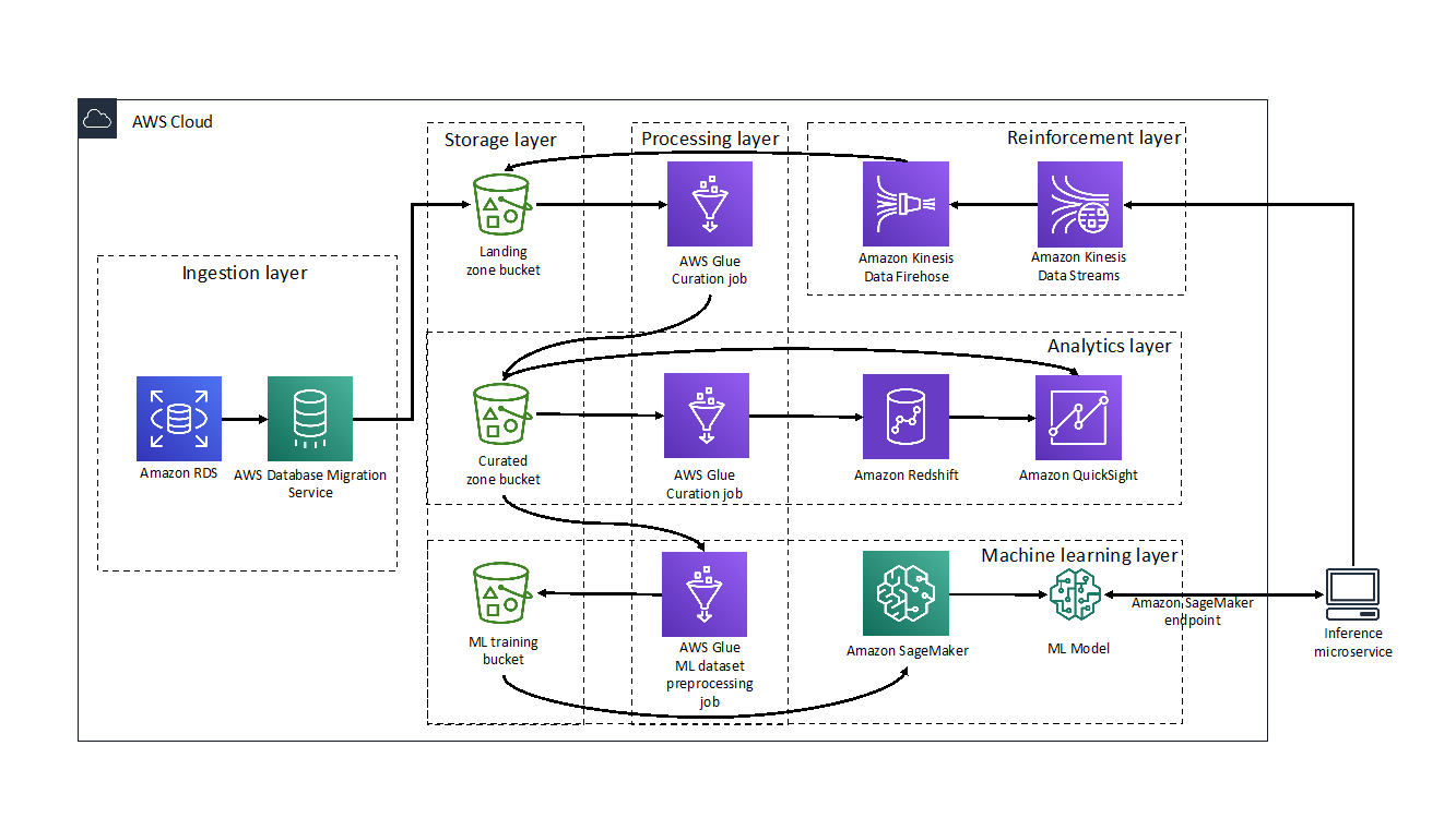
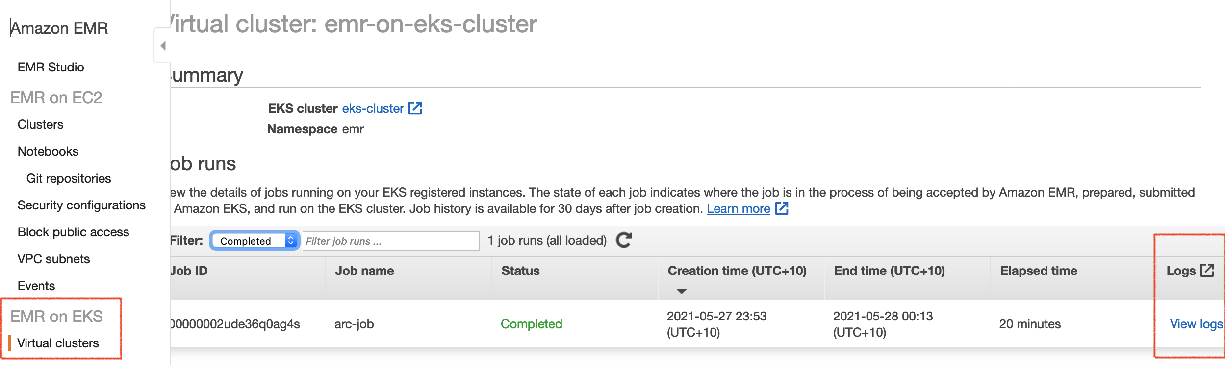
For this solution, MEDHOST and AWS built a layered pipeline consisting of ingestion, processing, storage, analytics, machine learning, and reinforcement components. The following diagram illustrates the Proof of Concept (POC) that was implemented during the four-day AWS Data Lab engagement.

Ingestion layer

The ingestion layer is responsible for moving data from hospital production databases to the landing zone of the pipeline.

The hospital data was stored in an Amazon RDS for PostgreSQL instance and moved to the landing zone of the data lake using AWS Database Migration Service (DMS). DMS made migrating databases to the cloud simple and secure. Using its ongoing replication feature, MEDHOST and AWS implemented change data capture (CDC) quickly and efficiently so MEDHOST team could spend more time focusing on the most interesting parts of the pipeline.

Processing layer

The processing layer was responsible for performing extract, tranform, load (ETL) on the data to curate them for subsequent uses.

MEDHOST used AWS Glue within its data pipeline for crawling its data layers and performing ETL tasks. The hospital data copied from RDS to Amazon S3 was cleaned, curated, enriched, denormalized, and stored in parquet format to act as the heart of the MEDHOST data lake and a single source of truth to serve any further data needs. During the four-day Data Lab, MEDHOST and AWS targeted two needs: powering MEDHOST’s data warehouse used for analytics and feeding training data to the machine learning prediction model. Even though there were multiple challenges, data curation is a critical task which requires an SME. AWS Glue’s serverless nature, along with the SME’s support during the Data Lab, made developing the required transformations cost efficient and uncomplicated. Scaling and cluster management was addressed by the service, which allowed the developers to focus on cleaning data coming from homogenous hospital sources and translating the business logic to code.

Storage layer

The storage layer provided low-cost, secure, and efficient storage infrastructure.

MEDHOST used Amazon S3 as a core component of its data lake. AWS DMS migration tasks saved data to S3 in .CSV format. Crawling data with AWS Glue made this landing zone data queryable and available for further processing. The initial AWS Glue ETL job stored the parquet formatted data to the data lake and its curated zone bucket. MEDHOST also used S3 to store the .CSV formatted data set that will be used to train, test, and validate its machine learning prediction model.

Analytics layer

The analytics layer gave MEDHOST pipeline reporting and dashboarding capabilities.

The data was in parquet format and partitioned in the curation zone bucket populated by the processing layer. This made querying with Amazon Athena or Amazon Redshift Spectrum fast and cost efficient.

From the Amazon Redshift cluster, MEDHOST created external tables that were used as staging tables for MEDHOST data warehouse and implemented an UPSERT logic to merge new data in its production tables. To showcase the reporting potential that was unlocked by the MEDHOST analytics layer, a connection was made to the Redshift cluster to Amazon QuickSight. Within minutes MEDHOST was able to create interactive analytics dashboards with filtering and drill-down capabilities such as a chart that showed the number of confirmed disease cases per US state.

Machine learning layer

The machine learning layer used MEDHOST’s existing data sets to train its cardiac risk prediction model and make it accessible via an endpoint.

Before getting into Data Lab, the MEDHOST team was not intimately familiar with machine learning. AWS Data Lab architects helped MEDHOST quickly understand concepts of machine learning and select a model appropriate for its use case. MEDHOST selected XGBoost as its model since cardiac prediction falls within regression technique. MEDHOST’s well architected data lake enabled it to quickly generate training, testing, and validation data sets using AWS Glue.

Amazon SageMaker abstracted underlying complexity of setting infrastructure for machine learning. With few clicks, MEDHOST started Jupyter notebook and coded the components leading to fitting and deploying its machine learning prediction model. Finally, MEDHOST created the endpoint for the model and ran REST calls to validate the endpoint and trained model. As a result, MEDHOST achieved the goal of predicting cardiac risk. Additionally, with Amazon QuickSight’s SageMaker integration, AWS made it easy to use SageMaker models directly in visualizations. QuickSight can call the model’s endpoint, send the input data to it, and put the inference results into the existing QuickSight data sets. This capability made it easy to display the results of the models directly in the dashboards. Read more about QuickSight’s SageMaker integration here.

Reinforcement layer

Finally, the reinforcement layer guaranteed that the results of the MEDHOST model were captured and processed to improve performance of the model.

The MEDHOST team went beyond the original goal and created an inference microservice to interact with the endpoint for prediction, enabled abstracting of the machine learning endpoint with the well-defined domain REST endpoint, and added a standard security layer to the MEDHOST application.

When there is a real-time call from the facility, the inference microservice gets inference from the SageMaker endpoint. Records containing input and inference data are fed to the data pipeline again. MEDHOST used Amazon Kinesis Data Streams to push records in real time. However, since retraining the machine learning model does not need to happen in real time, the Amazon Kinesis Data Firehose enabled MEDHOST to micro-batch records and efficiently save them to the landing zone bucket so that the data could be reprocessed.

Conclusion

Collaborating with AWS Data Lab enabled MEDHOST to:

  • Store single source of truth with low-cost storage solution (data lake)
  • Complete data pipeline for a low-cost data analytics solution
  • Create an almost production-ready code for cardiac risk prediction

The MEDHOST team learned many concepts related to data analytics and machine learning within four days. AWS Data Lab truly helped MEDHOST deliver results in an accelerated manner.


About the Authors

Pandian Velayutham is the Director of Engineering at MEDHOST. His team is responsible for delivering cloud solutions, integration and interoperability, and business analytics solutions. MEDHOST utilizes modern technology stack to provide innovative solutions to our customers. Pandian Velayutham is a technology evangelist and public cloud technology speaker.


George Komninos is a Data Lab Solutions Architect at AWS. He helps customers convert their ideas to a production-ready data product. Before AWS, he spent 3 years at Alexa Information domain as a data engineer. Outside of work, George is a football fan and supports the greatest team in the world, Olympiacos Piraeus.

Orchestrating and Monitoring Multichannel Messaging with Amazon Pinpoint

Post Syndicated from Hamilton Oliveira original https://aws.amazon.com/blogs/messaging-and-targeting/orchestrating-and-monitoring-multichannel-messaging-with-amazon-pinpoint/

The union of marketing and technology (MarTech) has contributed to making communications and customers interactions more dynamic and personalized. In a multichannel environment with increasingly connected customers, it is essential for a MarTech system to orchestrate a digital marketing strategy using customers’ preferred channels in addition to monitoring their effectiveness during these engagements.

Companies in a variety of industries, from financial and retail to manufacturing seek to communicate with customers in the most efficient way, at the right time and channels. One way to facilitate this communication is to engage the customer in a personalized multi-step experience, or journeys. Amazon Pinpoint is a tool that gives marketers the flexibility to create multi-channel campaigns and monitor end user interactions such as email opens and clicks.

In this blog post we’ll go deeper into how Amazon Pinpoint can be configured for customer interactions and orchestration. We’ll also learn how to monitor and observe the results of these interactions through other AWS services that complement the MarTech stack.

Enabling Multi-Channel on Amazon Pinpoint

Sign in to the Amazon Pinpoint console and choose a region where the service is available. To organize the settings, campaigns, segments, and data, marketers can create a project on Amazon Pinpoint. To do this, simply specify a name for the project in the Get started box and select Create a Project.

After creating the project, a number of options related to the newly created project will appear on the menu on the left.

The first step to getting a project running is to activate the desired channels. A channel represents the platform through which you engage your audience segment with messages.  Currently Amazon Pinpoint supports push notifications, email, SMS, voice and the creation of custom channels such as WhatsApp, Facebook Messenger or any other service that allows API integrations. In this blog post we will use the native Amazon Pinpoint channels: email, push notifications and SMS.

Let’s start by configuring the e-mail channel. From the menu related to the newly created project, navigate to Settings → Email and follow step 5 of the Creating an Amazon Pinpoint project with email support.

After configuring the email channel, we will start with configuring the SMS channel by navigating to Settings → SMS and Voice. Follow the walkthrough available in Setting up the Amazon Pinpoint SMS channel from the step 5. Then activate a phone number for the SMS service by following the steps on Requesting a number.

Note that Amazon Pinpoint supports more types of phone numbers in the United States than in other countries. Please review the available numbers within the United States and other countries. For testing in the United States a Toll Free Number (TFN) can be provisioned to the account immediately.

Remember that the usage of AWS services may incur costs and for detailed information about the costs regarding each service, by region, please visit this .

(Optional) Activate the push notification channel by going to, Settings → Push notifications and follow from Step 5 of the guide Setting up Amazon Pinpoint mobile push channels.

At the end of the settings, when accessing the Settings menu of the created project, you will see a similar screen like the following image.

We’ve now finished the channel configuration and are ready to move onto building Amazon Pinpoint Journeys.

Configuring Multi-Channel Experiences on Amazon Pinpoint Journeys

Now, let’s create a multichannel journey based on an external event. A journey is a personalized engagement experience made up of multiple steps across multiple channels. For example, in the case of a financial institution that wants to communicate with a customer over their preferred channel to notify the customer to activate a travel notice.

To simulate this use case, we will insert some endpoints. An Endpoint represents a destination that you can send messages, and a user can have one or more endpoints.

The example below is a json-document with 4 endpoints for 3 users, since the same user has two endpoints for two different channels. You should change the addresses to your own test email addresses, phone numbers, and push tokens, before using the example below.

Note that if your account is still in the sandbox these will need to be verified email addresses.

If you only have access to a single email address you can use labels by adding a plus sign (+) followed by a string of text after the local part of the address and before the at (@) sign.  For example: [email protected] and [email protected]

Then, the following steps:

  1. Create a json file based on the example below.
  2. Update the Address fields with your test email addresses and phone numbers.
  3. Run AWS CLI to import the JSON file created in step 1.
{
    "Item": [
        {
            "ChannelType": "EMAIL",
            "Address": "[email protected]",
            "Attributes": {
                "PreferredChannel": ["N"]
            },
            "Id": "example_endpoint_1",
            "User": {
                "UserId": "example_user_1",
                "UserAttributes": {
                    "FirstName": ["Richard"],
                    "LastName": ["Roe"]
                }
            }
        },
        {
            "ChannelType": "SMS",
            "Address": "+16145550100",
            "Attributes": {
                "PreferredChannel": ["Y"]
            },
            "Id": "example_endpoint_1b",
            "User": {
                "UserId": "example_user_1",
                "UserAttributes": {
                    "FirstName": ["Richard"],
                    "LastName": ["Roe"]
                }
            }
        },
        {
            "ChannelType": "SMS",
            "Address": "+16145550102",
            "Attributes": {
                "PreferredChannel": ["Y"]
            },
            "Id": "example_endpoint_2",
            "User": {
                "UserId": "example_user_2",
                "UserAttributes": {
                    "FirstName": ["Mary"],
                    "LastName": ["Major"]
                }
            }
        },
        {
            "ChannelType": "APNS",
            "Address": "1a2b3c4d5e6f7g8h9i0j1k2l3m4n5o6p7q8r9s0t1u2v3w4x5y6z7a8b9c0d1e2f",
            "Attributes": {
                "PreferredChannel": ["Y"]
            },
            "Id": "example_endpoint_3",
            "User": {
                "UserId": "example_user_3",
                "UserAttributes": {
                    "FirstName": ["Wang"],
                    "LastName": ["Xiulan"]
                }
            }
        }
    ]
}

Once the endpoints are inserted, let’s create 3 segments to represent each preferred channel — Email, Push Notifications, and SMS:

  1. Navigate to your project in the Amazon Pinpoint Console, choose Segments and then Create a segment.
  2. Select Build a segment.
  3. Provide a name for your segment, for example, SMS Preferred.
  4. Configure Segment Group 1 following the steps below to filter the endpoints where the preferred channel is SMS.
    1. Under Base segments, select Include any audiences
    2. Choose Add criteria and choose Channel Types → SMS.
    3. Choose Add filter, select Custom Endpoint Attributes → PreferredChannel, Operator Is, and on the dropdown choose Y.

Follow the same steps above for the Push and Email channels, choosing each of these channels in step 4.2. When you finish the configuration, you will have a result similar to the one presented below.

Next, let’s create the message templates for each of the channels. Follow the step-by-step in the User Guide for each of the following channels:

You should see the following:

Next, lets create the journey to notify users when a travel notice event occurs.

  1. Under your project Amazon Pinpoint Console, navigate to Journeys and choose Create journey.
    1. If this is your first time creating a Journey, click through the help messages
  2. Name your journey Travel Notice.
  3. Choose Set entry condition
    1. In Choose how to start the journey, select: Add participants when they perform an activity.
    2. In the field Events enter TravelNoticeAlert
    3. Choose Save.
  4. Click Add activity under the Journey Entry box and select Multivariate split
    1. Add 2 new branches by selecting Add Another Branch
    2. For the Branch A, under Choose a condition type, select Segment and for Segments choose E-mail Preferred
    3. For the Branch B, under Choose a condition type select Segment and for Segments choose SMSPreferred
    4. For the Branch C, under Choose a condition type select Segment and for Segments choose Push Preferred
    5. Leave everything else as the default values and select Save
  5. Finally, add a message sending activity for each segment.
    1. Under Branch A, select Add Activity, choose Send an email, then Choose an email template and select the template you created before for email channel.
    2. Choose Save.
    3. Under Branch B, select Add Activity, choose Send an SMS message, then Choose an SMS template and select the template you created before for SMS channel.
    4. Under Origination phone number, select the phone you configured when creating the SMS Channel
    5. Choose Save.
    6. Under Branch C, select Add Activity, choose Send a push notification activity, then Choose a push notification template and select the template you created before for push channel.
    7. Choose Save.
    8. When you complete these steps your journey will have a similar structure to the one presented below.
  6. Choose
    1. Under Review your journey choose Next, Mark as reviewed and finally Publish.
    2. Wait for the Journey to begin before continuing.

Installing Event Monitoring Components on Amazon Pinpoint

We can monitor and analysys the events generated by Amazon Pinpoint in real time by installing the Digital User Engagement Events Database solution, which is a reference implementation that installs the necessary services to track and query Amazon Pinpoint events.

To install this solution, follow the walkthrough available at Digital User Engagement Events Database Automated Deployment making sure to select the same region you used to configure Pinpoint earlier.

In Step 1. Launch the stack, for the Amazon Pinpoint Project ID field enter the Project ID that you created earlier, and leave the other fields as default. Wait for the end of the solution deployment. It will create a bucket in Amazon S3, a delivery stream in Amazon Kinesis Firehose, and a database and views in Amazon Athena, plus an AWS Lambda function responsible for partitioning the data.

Remember that the usage of AWS services may incur costs and for detailed information about the costs regarding the Digital User Engagement Events Database, please refer to the solution cost page.

Validating Your Multi-Channel Journey

Finally, we will use the commands below, to validate the event that triggers the journey and monitoring.

Note that we are using an Endpoint ID and not User ID.  Amazon Pinpoint will see that the endpoint is associated with a user and as such use the appropriate Preferred Channel for that user.

For the following commands you can use AWS CLI.

aws pinpoint put-events\
--application-id application-id\
--events-request '{"BatchItem": { "example_endpoint_1": { "Endpoint": {}, "Events": { "TravelNoticeAlert": {"EventType": "TravelNoticeAlert", "Timestamp": "2021-03-09T08:00:00Z"}}}}}'
aws pinpoint put-events\
--application-id application-id\
--events-request '{"BatchItem": { "example_endpoint_2": { "Endpoint": {}, "Events": { "TravelNoticeAlert": {"EventType": "TravelNoticeAlert", "Timestamp": "2021-03-09T08:00:00Z"}}}}}'
aws pinpoint put-events\
--application-id application-id\
--events-request '{"BatchItem": { "example_endpoint_3": { "Endpoint": {}, "Events": { "TravelNoticeAlert": {"EventType": "TravelNoticeAlert", "Timestamp": "2021-03-09T08:00:00Z"}}}}}'

application-id is your Amazon Pinpoint project ID. It can be accessed within AWS Pinpoint Console.

The value for the EventType parameter is the same you defined during the configuration of the Event field within the journey. In our example the value is TravelNoticeAlert.

Monitoring the Events of Your Multi-Channel Journey

Amazon Pinpoint natively offers a set of dashboards that can be accessed through the Analytics menu. However, with the architecture proposed in this blogpost it is possible to extract more detailed analysis. Navigate to the Amazon Athena console.

  1. Choose the Database due_eventdb that was configured by the solution above.
  2. Under New query tab copy and paste the statement below and choose Run query. The statement below creates a view that returns all endpoints to which SMS messages have been sent, with the status of sending at the telephone carrier. For more information about Views, access the topic Working With Views in Amazon Athena User Guide. Note that you may need to configure an S3 Bucket to store Athena Query Results.
    CREATE OR REPLACE VIEW sms_carrier_delivery AS
    SELECT event_type,
            client.client_id,
            from_unixtime(event_timestamp/1000) event_date,
            attributes['journey_activity_id'] journey_activity_id,
            attributes['destination_phone_number'] destination_phone_number, 
            attributes['record_status'] record_status
    FROM "due_eventdb"."all_events"
    WHERE event_type = '_SMS.SUCCESS'
    ORDER BY event_timestamp
  3. Open a new tab, copy and paste the following query, and select Run query. The command below creates a view that returns all endpoints to which SMS were sent, the message type (transactional or promotional), and the cost of sending.
    CREATE OR REPLACE VIEW sms_pricing AS
    SELECT event_type,
            client.client_id,
            from_unixtime(event_timestamp/1000) event_date,
            attributes['destination_phone_number'] destination_phone_number, 
            attributes['message_type'] message_type,
            metrics.price_in_millicents_usd/100000 sms_message_price
    FROM "due_eventdb"."all_events"
    WHERE event_type = '_SMS.SUCCESS'
    ORDER BY event_timestamp

To see all of the events available please refer to the Events Database Data Dictionary.

Finally, let’s further explore other monitoring options by creating dashboards in Amazon Quicksight.

From the AWS console, go to Amazon Quicksight and, if necessary, sign up.

  1. Select the top left menu where your username is and then Manage QuickSight.
    1. Select Security & permissions
    2. On QuickSight access to AWS services, select Add or remove.
    3. Check the option Amazon Athena, access Next and in S3 → S3 Buckets Linked To QuickSight Account.
      1. If the check box is clear, enable the check box next to Amazon S3.
      2. If the check box is already enabled, choose Details, and then choose Select S3 buckets.
    4. Check the S3 bucket created by the Digital User Engagement Events Database solution. If you have questions about the bucket name, check the Outputs tab for the value for the Dues3DataLakeName key of the CloudFormation stack you created.
    5. Select Finish and Update.
  2. Go back to the Amazon QuickSight home screen and select Datasets and then New dataset.
  3. Choose Athena.
  4. In Data source name field enter Pinpoint Dataset.
  5. Choose Validate connection, and Create data source.
    1. In the window Choose your table, in the Database: contain sets of tables select due_eventdb and the table sms_carrier_delivery.
    2. Select Edit/Preview data
    3. On the dataset definition screen press Save button.
  6. Choose Dataset
    1. Press the button New dataset.
    2. Scroll down to FROM EXISTING DATA SOURCES and access Pinpoint Dataset.
    3. Select Create dataset
    4. In the window Choose your table, in the Database: contain sets of tables select due_eventdb and the table sms_pricing.
    5. Select Edit/Preview data
    6. On the dataset definition screen press Save
    7. Repeat these steps again but select the journey_send table for the step
  7. Choose Analyses
    1. Press the button New analysis.
    2. For Your Datasets, choose journey_send and then access Create analysis. This view was created by Digital User Engagement Events Database solution.
    3. Under Field lists choose journey_send_status. Amazon QuickSight will draw a chart showing journeys events by status.
    4. Select the pen symbol next to Dataset and press the button Add dataset.
    5. Choose sms_carrier_delivery and Select.
    6. Choose the field record_status.
    7. Under Visual types, choose Pie chart. This chart will display message delivery status on your carrier.
    8. Press the pencil symbol next to Dataset and press the button Add dataset.
    9. Check sms_pricing and
    10. Choose sms_message_price and message_type
    11. Under Visual types, select Donut chart. This graph will display costs by transactional or promotional message type.

The final result will be something close to the one shown in the image below:

Conclusion

In this blogpost we walked through how to set up Amazon Pinpoint for an end-to-end scenario. We defined the basic components to a multichannel journey and monitoring, introduced AWS services as a MarTech solution that allows companies to send notifications to their customers preferred channels and also monitor their engagement data using Amazon Pinpoint events.

Clean up

  1. Choose AWS CloudFormation.
    1. Delete and Delete stack
  2. Navigate to Amazon Pinpoint console.
    1. Go to Settings → SMS and voice, select the number created during the execution of this blogpost and choose Remove phone number.
    2. Under All projects, open the created project and then in the menu on the left select Settings → General settings. Choose Delete project and confirm the deletion by filling “delete” in the indicated field and select Delete.
  3. Choose Amazon Quicksight.
    1. Delete your user.

Cross-Account Data Sharing for Amazon Redshift

Post Syndicated from Martin Beeby original https://aws.amazon.com/blogs/aws/cross-account-data-sharing-for-amazon-redshift/

To be successful in today’s fast-moving world, businesses need to analyze data quickly and take meaningful action. Many of our customers embrace this concept to become data-driven organizations.

Data-driven organizations treat data as an asset and use it to improve their insights and make better decisions. They unleash the power of data by using secure systems to collect, store, and process data and share it with people in their organization. Some even offer their data and analytics as a service, to their customers, partners, and external parties to create new revenue streams.

All stakeholders want to share and consume the same accurate data as a single source of truth. They want to be able to query live views of the data concurrently while experiencing no performance degradation and access the right information exactly when it’s needed.

Amazon Redshift, the first data warehouse built for the cloud, has become popular as the data warehouse component of many of our customers’ data architecture.

Amazon Redshift users can share data with users in an AWS account, but to share and collaborate on data with other AWS accounts, they needed to extract it from one system and load it into another.

There is a lot of manual work involved in building and maintaining the different extract, transform, and load jobs required to make this work. As your data sharing scales and more stakeholders need data, the complexity increases. As a result, it can become hard to maintain the monitoring, compliance, and security best practices required to keep your data safe.

This way of sharing does not provide complete and up-to-date views of the data, either, because the manual processes introduce delays and data inconsistencies that result in stale data, lower-quality business results, and slow responses to customers.

That’s why we created cross-account data sharing for Amazon Redshift.

Introducing Cross-Account Data Sharing for Amazon Redshift
This new feature gives you a simple and secure way to share fresh, complete, and consistent data in your Amazon Redshift data warehouse with any number of stakeholders across AWS accounts. It makes it possible for you to share data across organizations and collaborate with external parties while meeting compliance and security requirements.

Amazon Redshift offers comprehensive security controls and auditing capabilities using IAM integration, system tables and AWS CloudTrail. These allow customers to control and monitor data sharing permissions and usage across consumers and revoke access instantly when necessary.

You can share data at many levels, including databases, schemas, tables, views, columns, and user-defined functions, to provide fine-grained access controls tailored to users and businesses who need access to Amazon Redshift data.

Let’s take a look at how cross-account data sharing works.

Sharing Data Across Two Accounts

Cross-account data sharing is a two-step process. First, a producer cluster administrator creates a datashare, adds objects, and gives access to the consumer account. Second, the producer account administrator authorizes sharing data for the specified consumer. You can do this from the Amazon Redshift console.

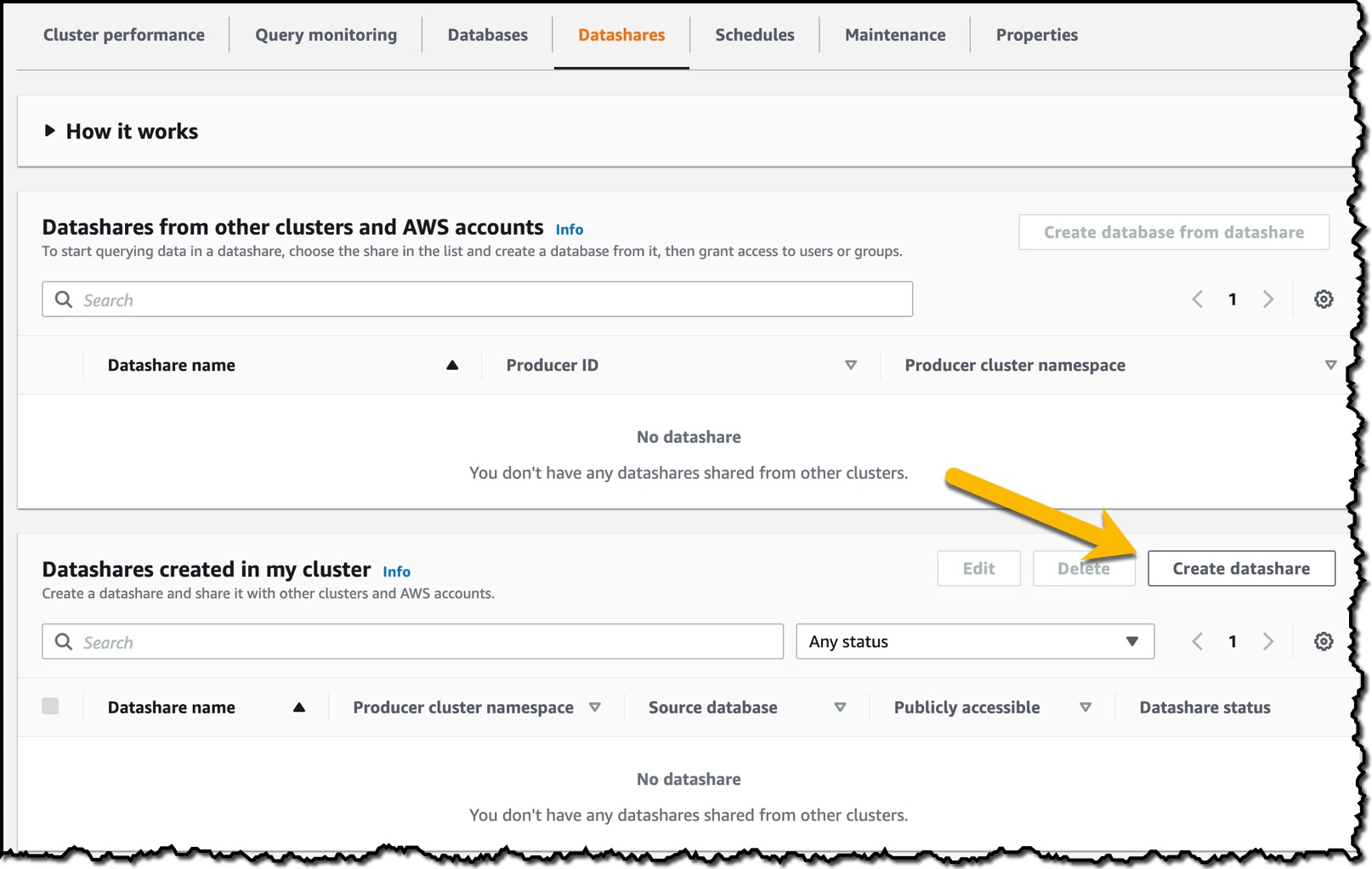
To get started, in the Amazon Redshift console, I create an Amazon Redshift cluster and then import some sample data. When the cluster is available, I navigate to the cluster details page, choose the Datashares tab, and then choose Create datashare.


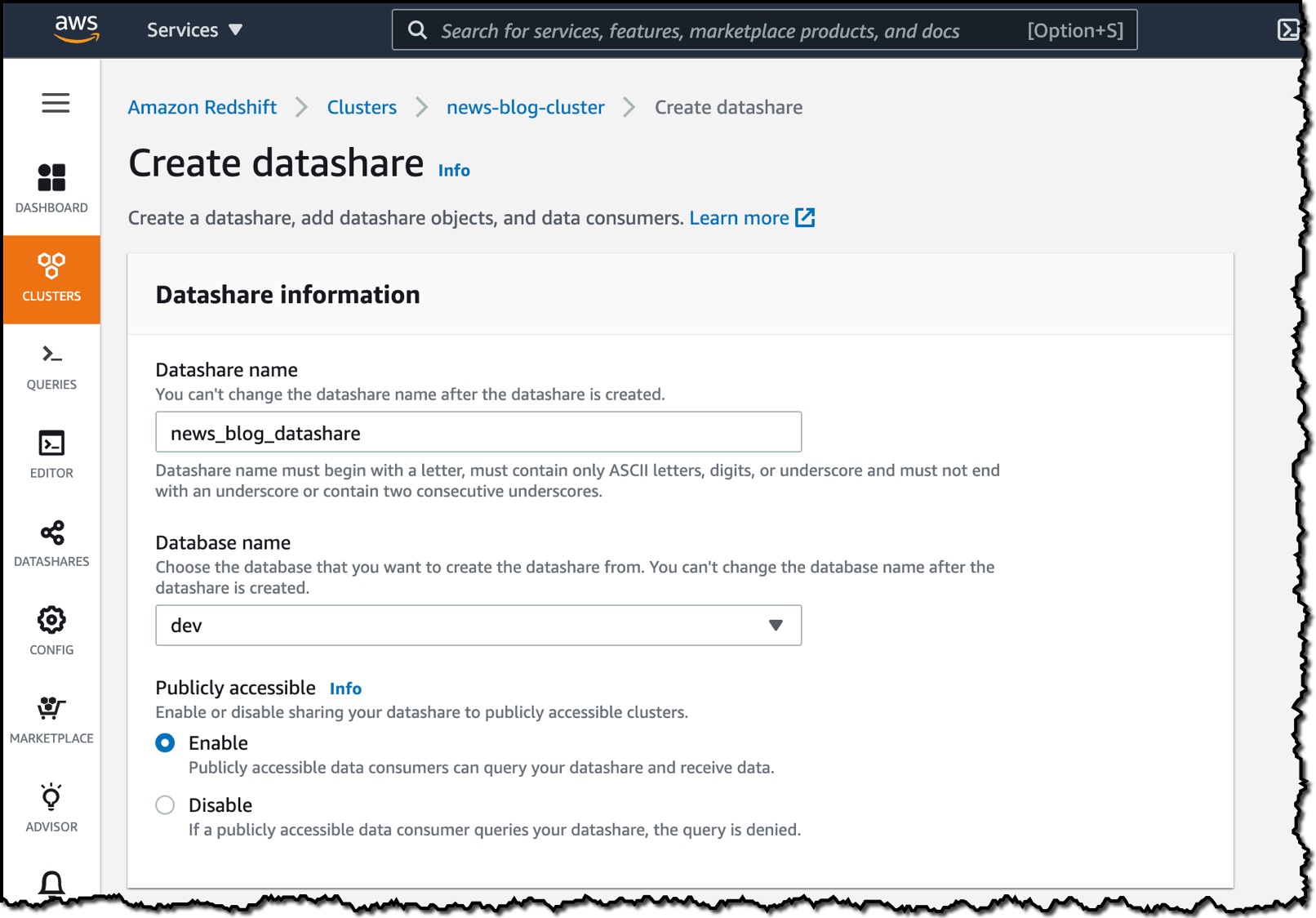
On the Create datashare page, I enter a datashare name and then choose a database. Under Publicly accessible, I choose Enable because I want the datashare to be shared with publicly accessible clusters.

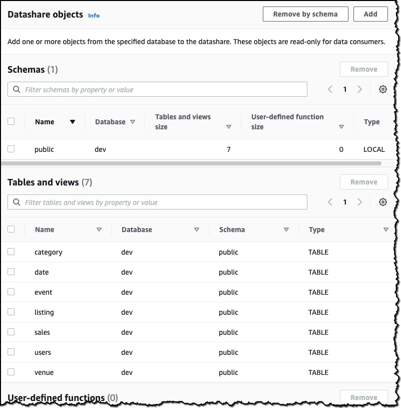
I then choose the objects from the database I want to include in the datashare. I have granular control of what I choose to share with others. For simplicity, I will share all the tables. In practice, though, you might choose one or more tables, views, or user-defined functions.

The last thing I need to do is add an AWS account to the datashare. I add my second AWS account ID and then choose Create datashare.

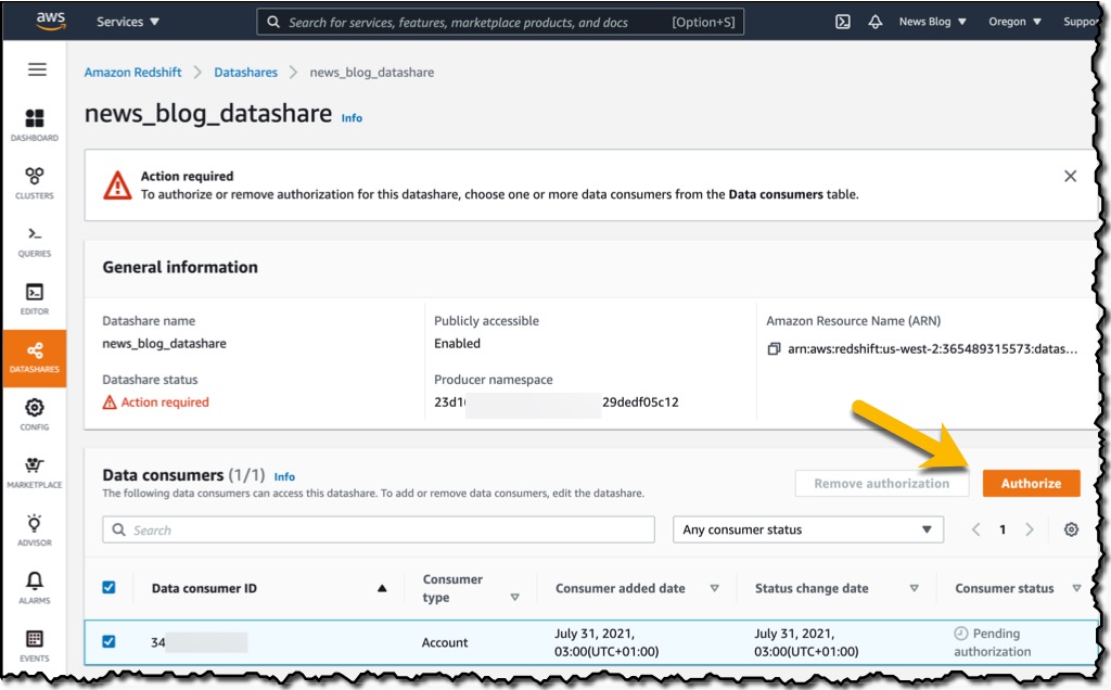
To authorize the data consumer I just created, in the Datashares section of the console, I choose Authorize. The Consumer status will change from Pending authorization to Authorized. Now that the datashare is set up, I’ll switch to my secondary account to show you how to consume the datashare in the consumer AWS account. It’s important to note that I need to use the same Region in the secondary account, as cross-account data sharing does not work across Regions.

Similar to the producer, there is a process for consuming data. First, you need to associate the data share with one or more clusters in the consumer account. You can also associate the data share to the entire consumer account so that the current and future clusters in the consumer account get access to the share.

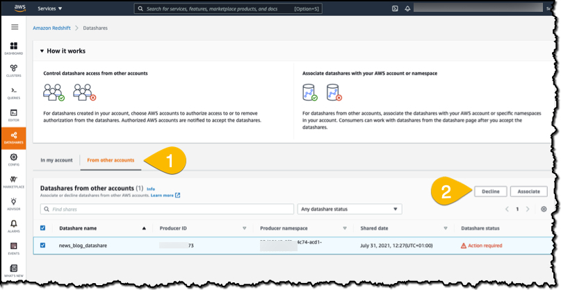
I sign in to my secondary account and go to the Datashares section of the console.  I choose the From other accounts tab and then select the news_blog_datashare that I shared from the producer AWS account. I then choose Associate to associate the datashare with a cluster in my account.

On the details page of the cluster, I choose Create database from datashare and then enter a name for my new database.

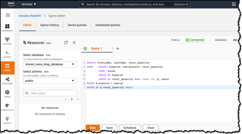
In the query editor, I select my database and run queries against all the objects that have been made available as part of the datashare.

When I choose Run, data is returned from the query. What’s important to remember is that this is a live view of the data. Any changes in the producer database will be reflected in my queries. No copying or manual transfers are required.

Things to Know

Here are a couple of interesting facts about cross-account data sharing:

Security – All of the permissions required for authorization and association are managed with AWS Identity and Access Management (IAM), so you can create IAM policies to control which operations each user can complete. For security considerations, see Controlling access for cross-account datashares.

Encryption – Both the producer and consumer clusters must be encrypted and in the same AWS Region.

Regions – Cross-account data sharing is available for all Amazon Redshift RA3 node types in US East (N. Virginia), US East (Ohio), US West (N. California), US West (Oregon), Asia Pacific (Mumbai), Asia Pacific (Seoul), Asia Pacific (Singapore), Asia Pacific (Sydney), Asia Pacific (Tokyo), Canada (Central), Europe (Frankfurt), Europe (Ireland), Europe (London), Europe (Paris), Europe (Stockholm), and South America (São Paulo).

Pricing – Cross-account data sharing is available across clusters that are in the same Region. There is no cost to share data. Customers just pay for the Redshift clusters that participate in sharing.

Try Cross-Account Data Sharing for Amazon Redshift today.

This new feature is available right now so why not create a cluster and take cross-account data sharing for a spin? For information about how to get started, see Sharing data across AWS accounts. Don’t forget to let me know how you get on.

Happy sharing!

— Martin

Address Modernization Tradeoffs with Lake House Architecture

Post Syndicated from Sukhomoy Basak original https://aws.amazon.com/blogs/architecture/address-modernization-tradeoffs-with-lake-house-architecture/

Many organizations are modernizing their applications to reduce costs and become more efficient. They must adapt to modern application requirements that provide 24×7 global access. The ability to scale up or down quickly to meet demand and process a large volume of data is critical. This is challenging while maintaining strict performance and availability. For many companies, modernization includes decomposing a monolith application into a set of independently developed, deployed, and managed microservices. The decoupled nature of a microservices environment allows each service to evolve agilely and independently. While there are many benefits for moving to a microservices-based architecture, there can be some tradeoffs. As your application monolith evolves into independent microservices, you must consider the implications to your data architecture.

In this blog post we will provide example use cases, and show how Lake House Architecture on AWS can streamline your microservices architecture. A Lake house architecture embraces the decentralized nature of microservices by facilitating data movement. These transfers can be between data stores, from data stores to data lake, and from data lake to data stores (Figure 1).

Figure 1. Integrating data lake, data warehouse, and all purpose-built stores into a coherent whole

Figure 1. Integrating data lake, data warehouse, and all purpose-built stores into a coherent whole

Health and wellness application challenges

Our fictitious health and wellness customer has an application architecture comprised of several microservices backed by purpose-built data stores. User profiles, assessments, surveys, fitness plans, health preferences, and insurance claims are maintained in an Amazon Aurora MySQL-Compatible relational database. The event service monitors the number of steps walked, sleep pattern, pulse rate, and other behavioral data in Amazon DynamoDB, a NoSQL database (Figure 2).

Figure 2. Microservices architecture for health and wellness company

Figure 2. Microservices architecture for health and wellness company

With this microservices architecture, it’s common to have data spread across various data stores. This is because each microservice uses a purpose-built data store suited to its usage patterns and performance requirements. While this provides agility, it also presents challenges to deriving needed insights.

Here are four challenges that different users might face:

  1. As a health practitioner, how do I efficiently combine the data from multiple data stores to give personalized recommendations that improve patient outcomes?
  2. As a sales and marketing professional, how do I get a 360 view of my customer, when data lives in multiple data stores? Profile and fitness data are in a relational data store, but important behavioral and clickstream data are in NoSQL data stores. It’s hard for me to run targeted marketing campaigns, which can lead to revenue loss.
  3. As a product owner, how do I optimize healthcare costs when designing wellbeing programs for patients?
  4. As a health coach, how do I find patients and help them with their wellness goals?

Our remaining subsections highlight AWS Lake House Architecture capabilities and features that allow data movement and the integration of purpose-built data stores.

1. Patient care use case

In this scenario, a health practitioner is interested in historical patient data to estimate the likelihood of a future outcome. To get the necessary insights and identify patterns, the health practitioner needs event data from Amazon DynamoDB and patient profile data from Aurora MySQL-Compatible. Our health practitioner will use Amazon Athena to run an ad-hoc analysis across these data stores.

Amazon Athena provides an interactive query service for both structured and unstructured data. The federated query functionality in Amazon Athena helps with running SQL queries across data stored in relational, NoSQL, and custom data sources. Amazon Athena uses Lambda-based data source connectors to run federated queries. Figure 3 illustrates the federated query architecture.

Figure 3. Amazon Athena federated query

Figure 3. Amazon Athena federated query

The patient care team could use an Amazon Athena federated query to find out if a patient needs urgent care. It is able to detect anomalies in the combined datasets from claims processing, device data, and electronic health record (HER) as show in Figure 4.

Figure 4. Federated query result by combining data from claim, device, and EHR stores

Figure 4. Federated query result by combining data from claim, device, and EHR stores

Healthcare data from various sources, including EHRs and genetic data, helps improve personalized care. Machine learning (ML) is able to harness big data and perform predictive analytics. This creates opportunities for researchers to develop personalized treatments for various diseases, including cancer and depression.

To achieve this, you must move all the related data into a centralized repository such as an Amazon S3 data lake. For specific use cases, you also must move the data between the purpose-built data stores. Finally, you must build an ML solution that can predict the outcome. Amazon Redshift ML, combined with its federated query processing capabilities enables data analysts and database developers to create a platform to detect patterns (Figure 5). With this platform, health practitioners are able to make more accurate, data-driven decisions.

Figure 5. Amazon Redshift federated query with Amazon Redshift ML

Figure 5. Amazon Redshift federated query with Amazon Redshift ML

2. Sales and marketing use case

To run marketing campaigns, the sales and marketing team must search customer data from a relational database, with event data in a non-relational data store. We will move the data from Aurora MySQL-Compatible and Amazon DynamoDB to Amazon Elasticsearch Service (ES) to meet this requirement.

AWS Database Migration Service (DMS) helps move the change data from Aurora MySQL-Compatible to Amazon ES using Change Data Capture (CDC). AWS Lambda could be used to move the change data from DynamoDB streams to Amazon ES, as shown in Figure 6.

Figure 6. Moving and combining data from Aurora MySQL-Compatible and Amazon DynamoDB to Amazon Elasticsearch Service

Figure 6. Moving and combining data from Aurora MySQL-Compatible and Amazon DynamoDB to Amazon Elasticsearch Service

The sales and marketing team can now run targeted marketing campaigns by querying data from Amazon Elasticsearch Service, see Figure 7. They can improve sales operations by visualizing data with Amazon QuickSight.

Figure 7. Personalized search experience for ad-tech marketing team

Figure 7. Personalized search experience for ad-tech marketing team

3. Healthcare product owner use case

In this scenario, the product owner must define the care delivery value chain. They must develop process maps for patient activity and estimate the cost of patient care. They must analyze these datasets by building business intelligence (BI) reporting and dashboards with a tool like Amazon QuickSight. Amazon Redshift, a cloud scale data warehousing platform, is a good choice for this. Figure 8 illustrates this pattern.

Figure 8. Moving data from Amazon Aurora and Amazon DynamoDB to Amazon Redshift

Figure 8. Moving data from Amazon Aurora and Amazon DynamoDB to Amazon Redshift

The product owners can use integrated business intelligence reports with Amazon Redshift to analyze their data. This way they can make more accurate and appropriate decisions, see Figure 9.

Figure 9. Business intelligence for patient care processes

Figure 9. Business intelligence for patient care processes

4. Health coach use case

In this scenario, the health coach must find a patient based on certain criteria. They would then send personalized communication to connect with the patient to ensure they are following the proposed health plan. This proactive approach contributes to a positive patient outcome. It can also reduce healthcare costs incurred by insurance companies.

To be able to search patient records with multiple data points, it is important to move data from Amazon DynamoDB to Amazon ES. This also will provide a fast and personalized search experience. The health coaches can be notified and will have the information they need to provide guidance to their patients. Figure 10 illustrates this pattern.

Figure 10. Moving Data from Amazon DynamoDB to Amazon ES

Figure 10. Moving Data from Amazon DynamoDB to Amazon ES

The health coaches can use Elasticsearch to search users based on specific criteria. This helps them with counseling and other health plans, as shown in Figure 11.

Figure 11. Simplified personalized search using patient device data

Figure 11. Simplified personalized search using patient device data

Summary

In this post, we highlight how Lake House Architecture on AWS helps with the challenges and tradeoffs of modernization. A Lake House architecture on AWS can help streamline the movement of data between the microservices data stores. This offers new capabilities for various analytics use cases.

For further reading on architectural patterns, and walkthroughs for building Lake House Architecture, see the following resources:

Easily manage your data lake at scale using AWS Lake Formation Tag-based access control

Post Syndicated from Nivas Shankar original https://aws.amazon.com/blogs/big-data/easily-manage-your-data-lake-at-scale-using-tag-based-access-control-in-aws-lake-formation/

Thousands of customers are building petabyte-scale data lakes on AWS. Many of these customers use AWS Lake Formation to easily build and share their data lakes across the organization. As the number of tables and users increase, data stewards and administrators are looking for ways to manage permissions on data lakes easily at scale. Customers are struggling with “role explosion” and need to manage hundreds or even thousands of user permissions to control data access. For example, for an account with 1,000 resources and 100 principals, the data steward would have to create and manage up to 100,000 policy statements. Furthermore, as new principals and resources get added or deleted, these policies have to be updated to keep the permissions current.

Lake Formation Tag-based access control solves this problem by allowing data stewards to create LF-tags (based on their data classification and ontology) that can then be attached to resources. You can create policies on a smaller number of logical tags instead of specifying policies on named resources. LF-tags enable you to categorize and explore data based on taxonomies, which reduces policy complexity and scales permissions management. You can create and manage policies with tens of logical tags instead of the thousands of resources. LF-tags access control decouples policy creation from resource creation, which helps data stewards manage permissions on a large number of databases, tables, and columns by removing the need to update policies every time a new resource is added to the data lake. Finally, LF-tags access allows you to create policies even before the resources come into existence. All you have to do is tag the resource with the right LF-tags to ensure it is managed by existing policies.

This post focuses on managing permissions on data lakes at scale using LF-tags in Lake Formation. When it comes to managing data lake catalog tables from AWS Glue and administering permission to Lake Formation, data stewards within the producing accounts have functional ownership based on the functions they support, and can grant access to various consumers, external organizations, and accounts. You can now define LF-tags; associate at the database, table, or column level; and then share controlled access across analytic, machine learning (ML), and extract, transform, and load (ETL) services for consumption. LF-tags ensures that governance can be scaled easily by replacing the policy definitions of thousands of resources with a small number of logical tags.

LF-tags access has three main components:

  • Tag ontology and classification – Data stewards can define a LF-tag ontology based on data classification and grant access based on LF-tags to AWS Identity and Access Management (IAM) principals and SAML principals or groups
  • Tagging resources – Data engineers can easily create, automate, implement, and track all LF-tags and permissions against AWS Glue catalogs through the Lake Formation API
  • Policy evaluation – Lake Formation evaluates the effective permissions based on LF-tags at query time and allows access to data through consuming services such as Amazon Athena, Amazon Redshift Spectrum, Amazon SageMaker Data Wrangler, and Amazon EMR Studio, based on the effective permissions granted across multiple accounts or organization-level data shares

Solution overview

The following diagram illustrates the architecture of the solution described in this post.

In this post, we demonstrate how you can set up a Lake Formation table and create Lake Formation tag-based policies using a single account with multiple databases. We walk you through the following high-level steps:

  1. The data steward defines the tag ontology with two LF-tags: Confidential and Sensitive. Data with “Confidential = True” has tighter access controls. Data with “Sensitive = True” requires specific analysis from the analyst.
  2. The data steward assigns different permission levels to the data engineer to build tables with different LF-tags.
  3. The data engineer builds two databases: tag_database and col_tag_database. All tables in tag_database are configured with “Confidential = True”. All tables in the col_tag_database are configured with “Confidential = False”. Some columns of the table in col_tag_database are tagged with “Sensitive = True” for specific analysis needs.
  4. The data engineer grants read permission to the analyst for tables with specific expression condition “Confidential = True” and  “Confidential = False , Sensitive = True”.
  5. With this configuration, the data analyst can focus on performing analysis with the right data.

Provision your resources

This post includes an AWS CloudFormation template for a quick setup. You can review and customize it to suit your needs. The template creates three different personas to perform this exercise and copies the nyc-taxi-data dataset to your local Amazon Simple Storage Service (Amazon S3) bucket.

To create these resources, complete the following steps:

  1. Sign in to the AWS CloudFormation console in the us-east-1 Region.
  2. Choose Launch Stack:
  3. Choose Next.
  4. In the User Configuration section, enter password for three personas: DataStewardUserPassword, DataEngineerUserPassword and DataAnalystUserPassword.
  5. Review the details on the final page and select I acknowledge that AWS CloudFormation might create IAM resources.
  6. Choose Create.

The stack takes up to 5 minutes and creates all the required resources, including:

  • An S3 bucket
  • The appropriate Lake Formation settings
  • The appropriate Amazon Elastic Compute Cloud (Amazon EC2) resources
  • Three user personas with user ID credentials:
    • Data steward (administrator) – The lf-data-steward user has the following access:
      • Read access to all resources in the Data Catalog
      • Can create LF-tags and associate to the data engineer role for grantable permission to other principals
    • Data engineer – The lf-data-engineer user has the following access:
      • Full read, write, and update access to all resources in the Data Catalog
      • Data location permissions in the data lake
      • Can associate LF-tags and associate to the Data Catalog
      • Can attach LF-tags to resources, which provides access to principals based on any policies created by data stewards
    • Data analyst – The lf-data-analyst user has the following access:
      • Fine-grained access to resources shared by Lake Formation Tag-based access policies

Register your data location and create an LF-tag ontology

We perform this first step as the data steward user (lf-data-steward) to verify the data in Amazon S3 and the Data Catalog in Lake Formation.

  1. Sign in to the Lake Formation console as lf-data-steward with the password used while deploying the CloudFormation stack.
  2. In the navigation pane, under Permissions¸ choose Administrative roles and tasks.
  3. For IAM users and roles, choose the user lf-data-steward.
  4. Choose Save to add lf-data-steward as a Lake Formation admin.

    Next, we will update the Data catalog settings to use Lake Formation permission to control catalog resources instead of IAM based access control.
  5. In the navigation pane, under Data catalog¸ choose Settings.
  6. Uncheck Use only IAM access control for new databases.
  7. Uncheck Use only IAM access control for new tables in new databases.
  8. Click Save.

    Next, we need to register the data location for the data lake.
  9. In the navigation pane, under Register and ingest, choose Data lake locations.
  10. For Amazon S3 path, enter s3://lf-tagbased-demo-<<Account-ID>>.
  11. For IAM role¸ leave it as the default value AWSServiceRoleForLakeFormationDataAccess.
  12. Choose Register location.
    Next, we create the ontology by defining a LF-tag.
  13. Under Permissions in the navigation pane, under Administrative roles, choose LF-Tags.
  14. Choose Add LF-tags.
  15. For Key, enter Confidential.
  16. For Values, add True and False.
  17. Choose Add LF-tag.
  18. Repeat the steps to create the LF-tag Sensitive with the value True.
    You have created all the necessary LF-tags for this exercise.Next, we give specific IAM principals the ability to attach newly created LF-tags to resources.
  19. Under Permissions in the navigation pane, under Administrative roles, choose LF-tag permissions.
  20. Choose Grant.
  21. Select IAM users and roles.
  22. For IAM users and roles, search for and choose the lf-data-engineer role.
  23. In the LF-tag permission scope section, add the key Confidential with values True and False, and the key Sensitive with value True.
  24. Under Permissions¸ select Describe and Associate for LF-tag permissions and Grantable permissions.
  25. Choose Grant.

    Next, we grant permissions to lf-data-engineer to create databases in our catalog and on the underlying S3 bucket created by AWS CloudFormation.
  26. Under Permissions in the navigation pane, choose Administrative roles.
  27. In the Database creators section, choose Grant.
  28. For IAM users and roles, choose the lf-data-engineer role.
  29. For Catalog permissions, select Create database.
  30. Choose Grant.

    Next, we grant permissions on the S3 bucket (s3://lf-tagbased-demo-<<Account-ID>>) to the lf-data-engineer user.
  31. In the navigation pane, choose Data locations.
  32. Choose Grant.
  33. Select My account.
  34. For IAM users and roles, choose the lf-data-engineer role.
  35. For Storage locations, enter the S3 bucket created by the CloudFormation template (s3://lf-tagbased-demo-<<Account-ID>>).
  36. Choose Grant.
    Next, we grant lf-data-engineer grantable permissions on resources associated with the LF-tag expression Confidential=True.
  37. In the navigation pane, choose Data permissions.
  38. Choose Grant.
  39. Select IAM users and roles.
  40. Choose the role lf-data-engineer.
  41. In the LF-tag or catalog resources section, Select Resources matched by LF-Tags.
  42. Choose Add LF-Tag.
  43. Add the key Confidential with the values True.
  44. In the Database permissions section, select Describe for Database permissions and Grantable permissions.
  45. In the Table and column permissions section, select Describe, Select, and Alter for both Table permissions and Grantable permissions.
  46. Choose Grant.
    Next, we grant lf-data-engineer grantable permissions on resources associated with the LF-tag expression Confidential=False.
  47. In the navigation pane, choose Data permissions.
  48. Choose Grant.
  49. Select IAM users and roles.
  50. Choose the role lf-data-engineer.
  51. Select Resources matched by LF-tags.
  52. Choose Add LF-tag.
  53. Add the key Confidential with the values False.
  54. In the Database permissions section, select Describe for Database permissions and Grantable permissions.
  55. In the Table and column permissions section, do not select anything.
  56. Choose Grant.
    Next, we grant lf-data-engineer grantable permissions on resources associated with the LF-tag expression Confidential=False and Sensitive=True.
  57. In the navigation pane, choose Data permissions.
  58. Choose Grant.
  59. Select IAM users and roles.
  60. Choose the role lf-data-engineer.
  61. Select Resources matched by LF-tags.
  62. Choose Add LF-tag.
  63. Add the key Confidential with the values False.
  64. Choose Add LF-tag.
  65. Add the key Sensitive with the values True.
  66. In the Database permissions section, select Describe for Database permissions and Grantable permissions.
  67. In the Table and column permissions section, select Describe, Select, and Alter for both Table permissions and Grantable permissions.
  68. Choose Grant.

Create the Lake Formation databases

Now, sign in as lf-data-engineer with the password used while deploying the CloudFormation stack. We create two databases and attach LF-tags to the databases and specific columns for testing purposes.

Create your database and table for database-level access

We first create the database tag_database, the table source_data, and attach appropriate LF-tags.

  1. On the Lake Formation console, choose Databases.
  2. Choose Create database.
  3. For Name, enter tag_database.
  4. For Location, enter the S3 location created by the CloudFormation template (s3://lf-tagbased-demo-<<Account-ID>>/tag_database/).
  5. Deselect Use only IAM access control for new tables in this database.
  6. Choose Create database.

Next, we create a new table within tag_database.

  1. On the Databases page, select the database tag_database.
  2. Choose View Tables and click Create table.
  3. For Name, enter source_data.
  4. For Database, choose the database tag_database.
  5. For Data is located in, select Specified path in my account.
  6. For Include path, enter the path to tag_database created by the CloudFormation template (s3://lf-tagbased-demo-<<Account-ID>>/tag_database/).
  7. For Data format, select CSV.
  8. Under Upload schema, enter the following schema JSON:
    [
                   {
                        "Name": "vendorid",
                        "Type": "string"
                        
                        
                   },
                   {
                        "Name": "lpep_pickup_datetime",
                        "Type": "string"
                        
                        
                   },
                   {
                        "Name": "lpep_dropoff_datetime",
                        "Type": "string"
                        
                        
                   },
                      {
                        "Name": "store_and_fwd_flag",
                        "Type": "string"
                        
                        
                   },
                      {
                        "Name": "ratecodeid",
                        "Type": "string"
                        
                        
                   },
                      {
                        "Name": "pulocationid",
                        "Type": "string"
                        
                        
                   },
                   {
                        "Name": "dolocationid",
                        "Type": "string"
                        
                        
                   },
                      {
                        "Name": "passenger_count",
                        "Type": "string"
                        
                        
                   },
                   {
                        "Name": "trip_distance",
                        "Type": "string"
                        
                        
                   }, 
                      {
                        "Name": "fare_amount",
                        "Type": "string"
                        
                        
                   },
                   {
                        "Name": "extra",
                        "Type": "string"
                        
                        
                   },
                      {
                        "Name": "mta_tax",
                        "Type": "string"
                        
                        
                   },
                   {
                        "Name": "tip_amount",
                        "Type": "string"
                        
                        
                   },
                      {
                        "Name": "tolls_amount",
                        "Type": "string"
                        
                        
                   },
                   {
                        "Name": "ehail_fee",
                        "Type": "string"
                        
                        
                   }, 
                   {
                        "Name": "improvement_surcharge",
                        "Type": "string"
                        
                        
                   },
                   {
                        "Name": "total_amount",
                        "Type": "string"
                        
                        
                   },
                   {
                        "Name": "payment_type",
                        "Type": "string"
                        
                        
                   }
     
    ]
    

  9. Choose Upload.

After uploading the schema, the table schema should look like the following screenshot.

  1. Choose Submit.

Now we’re ready to attach LF-tags at the database level.

  1. On the Databases page, find and select tag_database.
  2. On the Actions menu, choose Edit LF-tags.
  3. Choose Assign new LF-tag.
  4. For Assigned keys¸ choose the Confidential LF-tag you created earlier.
  5. For Values, choose True.
  6. Choose Save.

This completes the LF-tag assignment to the tag_database database.

Create your database and table for column-level access

Now we repeat these steps to create the database col_tag_database and table source_data_col_lvl, and attach LF-tags at the column level.

  1. On the Databases page, choose Create database.
  2. For Name, enter col_tag_database.
  3. For Location, enter the S3 location created by the CloudFormation template (s3://lf-tagbased-demo-<<Account-ID>>/col_tag_database/).
  4. Deselect Use only IAM access control for new tables in this database.
  5. Choose Create database.
  6. On the Databases page, select your new database (col_tag_database).
  7. Choose View tables and Click Create table.
  8. For Name, enter source_data_col_lvl.
  9. For Database, choose your new database (col_tag_database).
  10. For Data is located in, select Specified path in my account.
  11. Enter the S3 path for col_tag_database (s3://lf-tagbased-demo-<<Account-ID>>/col_tag_database/).
  12. For Data format, select CSV.
  13. Under Upload schema, enter the following schema JSON:
    [
                   {
                        "Name": "vendorid",
                        "Type": "string"
                        
                        
                   },
                   {
                        "Name": "lpep_pickup_datetime",
                        "Type": "string"
                        
                        
                   },
                   {
                        "Name": "lpep_dropoff_datetime",
                        "Type": "string"
                        
                        
                   },
                      {
                        "Name": "store_and_fwd_flag",
                        "Type": "string"
                        
                        
                   },
                      {
                        "Name": "ratecodeid",
                        "Type": "string"
                        
                        
                   },
                      {
                        "Name": "pulocationid",
                        "Type": "string"
                        
                        
                   },
                   {
                        "Name": "dolocationid",
                        "Type": "string"
                        
                        
                   },
                      {
                        "Name": "passenger_count",
                        "Type": "string"
                        
                        
                   },
                   {
                        "Name": "trip_distance",
                        "Type": "string"
                        
                        
                   }, 
                      {
                        "Name": "fare_amount",
                        "Type": "string"
                        
                        
                   },
                   {
                        "Name": "extra",
                        "Type": "string"
                        
                        
                   },
                      {
                        "Name": "mta_tax",
                        "Type": "string"
                        
                        
                   },
                   {
                        "Name": "tip_amount",
                        "Type": "string"
                        
                        
                   },
                      {
                        "Name": "tolls_amount",
                        "Type": "string"
                        
                        
                   },
                   {
                        "Name": "ehail_fee",
                        "Type": "string"
                        
                        
                   }, 
                   {
                        "Name": "improvement_surcharge",
                        "Type": "string"
                        
                        
                   },
                   {
                        "Name": "total_amount",
                        "Type": "string"
                        
                        
                   },
                   {
                        "Name": "payment_type",
                        "Type": "string"
                        
                        
                   }
     
    ]
    

  14. Choose Upload.

After uploading the schema, the table schema should look like the following screenshot.

  1. Choose Submit to complete the creation of the table

Now you associate the  Sensitive=True LF-tag to the columns vendorid and fare_amount.

  1. On the Tables page, select the table you created (source_data_col_lvl).
  2. On the Actions menu, choose Edit Schema.
  3. Select the column vendorid and choose Edit LF-tags.
  4. For Assigned keys, choose Sensitive.
  5. For Values, choose True.
  6. Choose Save.

Repeat the steps for the Sensitive LF-tag update for fare_amount column.

  1. Select the column fare_amount and choose Edit LF-tags.
  2. Add the Sensitive key with value True.
  3. Choose Save.
  4. Choose Save as new version to save the new schema version with tagged columns.The following screenshot shows column properties with the LF-tags updated.
    Next we associate the Confidential=False LF-tag to col_tag_database. This is required for lf-data-analyst to be able to describe the database col_tag_database when logged in from Athena.
  5. On the Databases page, find and select col_tag_database.
  6. On the Actions menu, choose Edit LF-tags.
  7. Choose Assign new LF-tag.
  8. For Assigned keys¸ choose the Confidential LF-tag you created earlier.
  9. For Values, choose False.
  10. Choose Save.

Grant table permissions

Now we grant permissions to data analysts for consumption of the database tag_database and the table col_tag_database.

  1. Sign in to the Lake Formation console as lf-data-engineer.
  2. On the Permissions page, select Data Permissions
  3. Choose Grant.
  4. Under Principals, select IAM users and roles.
  5. For IAM users and roles, choose lf-data-analyst.
  6. Select Resources matched by LF-tags.
  7. Choose Add LF-tag.
  8. For Key, choose Confidential.
  9. For Values¸ choose True.
  10. For Database permissions, select Describe
  11. For Table permissions, choose Select and Describe.
  12. Choose Grant.

    This grants permissions to the lf-data-analyst user on the objects associated with the LF-tag Confidential=True (Database : tag_database)  to describe the database and the select permission on tables.Next, we repeat the steps to grant permissions to data analysts for LF-tag expression for Confidential=False . This LF-tag is used for describing the col_tag_database and the table source_data_col_lvl when logged in as lf-data-analyst from Athena. And so, we only grant describe access to the resources through this LF-tag expression.
  13. Sign in to the Lake Formation console as lf-data-engineer.
  14. On the Databases page, select the database col_tag_database.
  15. Choose Action and Grant.
  16. Under Principals, select IAM users and roles.
  17. For IAM users and roles, choose lf-data-analyst.
  18. Select Resources matched by LF-tags.
  19. Choose Add LF-tag.
  20. For Key, choose Confidential.
  21. For Values¸ choose False.
  22. For Database permissions, select Describe.
  23. For Table permissions, do not select anything.
  24. Choose Grant.

    Next, we repeat the steps to grant permissions to data analysts for LF-tag expression for Confidential=False and Sensitive=True. This LF-tag is used for describing the col_tag_database and the table source_data_col_lvl (Column level) when logged in as lf-data-analyst from Athena.
  25. Sign in to the Lake Formation console as lf-data-engineer.
  26. On the Databases page, select the database col_tag_database.
  27. Choose Action and Grant.
  28. Under Principals, select IAM users and roles.
  29. For IAM users and roles, choose lf-data-analyst.
  30. Select Resources matched by LF-tags.
  31. Choose Add LF-tag.
  32. For Key, choose Confidential.
  33. For Values¸ choose False.
  34. Choose Add LF-tag.
  35. For Key, choose Sensitive.
  36. For Values¸ choose True.
  37. For Database permissions, select Describe.
  38. For Database permissions, select Describe.
  39. For Table permissions, select Select and Describe.
  40. Choose Grant.

Run a query in Athena to verify the permissions

For this step, we sign in to the Athena console as lf-data-analyst and run SELECT queries against the two tables (source_data and source_data_col_lvl). We use our S3 path as the query result location (s3://lf-tagbased-demo-<<Account-ID>>/athena-results/).

  1. In the Athena query editor, choose tag_database in the left panel.
  2. Choose the additional menu options icon (three vertical dots) next to source_data and choose Preview table.
  3. Choose Run query.

The query should take a few minutes to run. The following screenshot shows our query results.

The first query displays all the columns in the output because the LF-tag is associated at the database level and the source_data table automatically inherited the LF-tag from the database tag_database.

  1. Run another query using col_tag_database and source_data_col_lvl.

The second query returns just the two columns that were tagged (Non-Confidential and Sensitive).

As a thought experiment, you can also check to see the Lake Formation Tag-based access policy behavior on columns to which the user doesn’t have policy grants.

When an untagged column is selected from the table source_data_col_lvl, Athena returns an error. For example, you can run the following query to choose untagged columns geolocationid:

SELECT geolocationid FROM "col_tag_database"."source_data_col_lvl" limit 10;

Extend the solution to cross-account scenarios

You can extend this solution to share catalog resources across accounts. The following diagram illustrates a cross-account architecture.

We describe this in more detail in a subsequent post.

Clean up

To help prevent unwanted charges to your AWS account, you can delete the AWS resources that you used for this walkthrough.

  1. Sign in as lf-data-engineer Delete the databases tag_database and col_tag_database
  2. Now, Sign in as lf-data-steward and clean up all the LF-tag Permissions, Data Permissions and Data Location Permissions that were granted above that were granted lf-data-engineer and lf-data-analyst.
  3. Sign in to the Amazon S3 console as the account owner (the IAM credentials you used to deploy the CloudFormation stack).
  4. Delete the following buckets:
    1. lf-tagbased-demo-accesslogs-<acct-id>
    2. lf-tagbased-demo-<acct-id>
  5. On the AWS CloudFormation console, delete the stack you created.
  6. Wait for the stack status to change to DELETE_COMPLETE.

Conclusion

In this post, we explained how to create a LakeFormation Tag-based access control policy in Lake Formation using an AWS public dataset. In addition, we explained how to query tables, databases, and columns that have LakeFormation Tag-based access policies associated with them.

You can generalize these steps to share resources across accounts. You can also use these steps to grant permissions to SAML identities. In subsequent posts, we highlight these use cases in more detail.


About the Authors

Sanjay Srivastava is a principal product manager for AWS Lake Formation. He is passionate about building products, in particular products that help customers get more out of their data. During his spare time, he loves to spend time with his family and engage in outdoor activities including hiking, running, and gardening.



Nivas Shankar is a Principal Data Architect at Amazon Web Services. He helps and works closely with enterprise customers building data lakes and analytical applications on the AWS platform. He holds a master’s degree in physics and is highly passionate about theoretical physics concepts.


Pavan Emani is a Data Lake Architect at AWS, specialized in big data and analytics solutions. He helps customers modernize their data platforms on the cloud. Outside of work, he likes reading about space and watching sports.
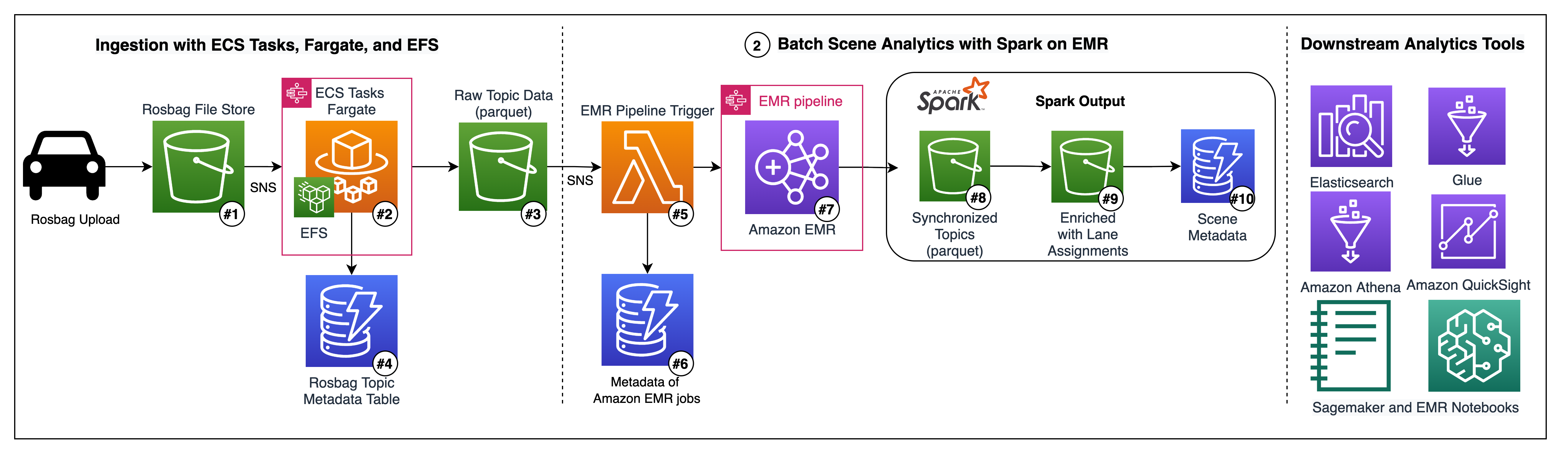
 

Field Notes: Building an automated scene detection pipeline for Autonomous Driving – ADAS Workflow

Post Syndicated from Kevin Soucy original https://aws.amazon.com/blogs/architecture/field-notes-building-an-automated-scene-detection-pipeline-for-autonomous-driving/

This Field Notes blog post in 2020 explains how to build an Autonomous Driving Data Lake using this Reference Architecture. Many organizations face the challenge of ingesting, transforming, labeling, and cataloging massive amounts of data to develop automated driving systems. In this re:Invent session, we explored an architecture to solve this problem using Amazon EMR, Amazon S3, Amazon SageMaker Ground Truth, and more. You learn how BMW Group collects 1 billion+ km of anonymized perception data from its worldwide connected fleet of customer vehicles to develop safe and performant automated driving systems.

Architecture Overview

The objective of this post is to describe how to design and build an end-to-end Scene Detection pipeline which:

This architecture integrates an event-driven ROS bag ingestion pipeline running Docker containers on Elastic Container Service (ECS). This includes a scalable batch processing pipeline based on Amazon EMR and Spark. The solution also leverages AWS Fargate, Spot Instances, Elastic File System, AWS Glue, S3, and Amazon Athena.

reference architecture - build automated scene detection pipeline - Autonomous Driving

Figure 1 – Architecture Showing how to build an automated scene detection pipeline for Autonomous Driving

The data included in this demo was produced by one vehicle across four different drives in the United States. As the ROS bag files produced by the vehicle’s on-board software contains very complex data, such as Lidar Point Clouds, the files are usually very large (1+TB files are not uncommon).

These files usually need to be split into smaller chunks before being processed, as is the case in this demo. These files also may need to have post-processing algorithms applied to them, like lane detection or object detection.

In our case, the ROS bag files are split into approximately 10GB chunks and include topics for post-processed lane detections before they land in our S3 bucket. Our scene detection algorithm assumes the post processing has already been completed. The bag files include object detections with bounding boxes, and lane points representing the detected outline of the lanes.

Prerequisites

This post uses an AWS Cloud Development Kit (CDK) stack written in Python. You should follow the instructions in the AWS CDK Getting Started guide to set up your environment so you are ready to begin.

You can also use the config.json to customize the names of your infrastructure items, to set the sizing of your EMR cluster, and to customize the ROS bag topics to be extracted.

You will also need to be authenticated into an AWS account with permissions to deploy resources before executing the deploy script.

Deployment

The full pipeline can be deployed with one command: * `bash deploy.sh deploy true` . The progress of the deployment can be followed on the command line, but also in the CloudFormation section of the AWS console. Once deployed, the user must upload 2 or more bag files to the rosbag-ingest bucket to initiate the pipeline.

The default configuration requires two bag files to be processed before an EMR Pipeline is initiated. You would also have to manually initiate the AWS  Glue Crawler to be able to explore the parquet data with tools like Athena or Quicksight.

ROS bag ingestion with ECS Tasks, Fargate, and EFS

This solution provides an end-to-end scene detection pipeline for ROS bag files, ingesting the ROS bag files from S3, and transforming the topic data to perform scene detection in PySpark on EMR. This then exposes scene descriptions via DynamoDB to downstream consumers.

The pipeline starts with an S3 bucket (Figure 1 – #1) where incoming ROS bag files can be uploaded from local copy stations as needed. We recommend, using Amazon Direct Connect for a private, high-throughout connection to the cloud.

This ingestion bucket is configured to initiate S3 notifications each time an object ending in the prefix “.bag” is created. An AWS Lambda function then initiates a Step Function for orchestrating the ECS Task. This passes the bucket and bag file prefix to the ECS task as environment variables in the container.

The ECS Task (Figure 1 – #2) runs serverless leveraging Fargate as the capacity provider, This avoids the need to provision and autoscale EC2 instances in the ECS cluster. Each ECS Task processes exactly one bag file. We use Elastic FileStore to provide virtually unlimited file storage to the container, in order to easily work with larger bag files. The container uses the open-source bagpy python library to extract structured topic data (for example, GPS, detections, inertial measurement data,). The topic data is uploaded as parquet files to S3, partitioned by topic and source bag file. The application writes metadata about each file, such as the topic names found in the file and the number of messages per topic, to a DynamoDB table (Figure 1 – #4).

This module deploys an AWS  Glue Crawler configured to crawl this bucket of topic parquet files. These files populate the AWS Glue Catalog with the schemas of each topic table and make this data accessible in Athena, Glue jobs, Quicksight, and Spark on EMR.  We use the AWS Glue Catalog (Figure 1 – #5) as a permanent Hive Metastore.

Glue Data Catalog of parquet datasets on S3

Figure 2 – Glue Data Catalog of parquet datasets on S3


Run ad-hoc queries against the Glue tables using Amazon Athena

Figure 3 – Run ad-hoc queries against the Glue tables using Amazon Athena

The topic parquet bucket also has an S3 Notification configured for all newly created objects, which is consumed by an EMR-Trigger Lambda (Figure 1 – #5). This Lambda function is responsible for keeping track of bag files and their respective parquet files in DynamoDB (Figure 1 – #6). Once in DynamoDB, bag files are assigned to batches, initiating the EMR batch processing step function. Metadata is stored about each batch including the step function execution ARN in DynamoDB.

EMR pipeline orchestration with AWS Step Functions

Figure 4 – EMR pipeline orchestration with AWS Step Functions

The EMR batch processing step function (Figure 1 – #7) orchestrates the entire EMR pipeline, from provisioning an EMR cluster using the open-source EMR-Launch CDK library to submitting Pyspark steps to the cluster, to terminating the cluster and handling failures.

Batch Scene Analytics with Spark on EMR

There are two PySpark applications running on our cluster. The first performs synchronization of ROS bag topics for each bagfile. As the various sensors in the vehicle have different frequencies, we synchronize the various frequencies to a uniform frequency of 1 signal per 100 ms per sensor. This makes it easier to work with the data.

We compute the minimum and maximum timestamp in each bag file, and construct a unified timeline. For each 100 ms we take the most recent signal per sensor and assign it to the 100 ms timestamp. After this is performed, the data looks more like a normal relational table and is easier to query and analyze.

Batch Scene Analytics with Spark on EMR

Figure 5 – Batch Scene Analytics with Spark on EMR

Scene Detection and Labeling in PySpark

The second spark application enriches the synchronized topic dataset (Figure 1 – #8), analyzing the detected lane points and the object detections. The goal is to perform a simple lane assignment algorithm for objects detected by the on-board ML models and to save this enriched dataset (Figure 1 – #9) back to S3 for easy-access by analysts and data scientists.

Object Lane Assignment Example

Figure 9 – Object Lane Assignment example


Synchronized topics enriched with object lane assignments

Figure 9 – Synchronized topics enriched with object lane assignments

Finally, the last step takes this enriched dataset (Figure 1 – #9) to summarize specific scenes or sequences where a person was identified as being in a lane. The output of this pipeline includes two new tables as parquet files on S3 – the synchronized topic dataset (Figure 1 – #8) and the synchronized topic dataset enriched with object lane assignments (Figure 1 – #9), as well as a DynamoDB table with scene metadata for all person-in-lane scenarios (Figure 1 – #10).

Scene Metadata

The Scene Metadata DynamoDB table (Figure 1 – #10) can be queried directly to find sequences of events, as will be covered in a follow up post for visually debugging scene detection algorithms using WebViz/RViz. Using WebViz, we were able to detect that the on-board object detection model labels Crosswalks and Walking Signs as “person” even when a person is not crossing the street, for example:

Example DynamoDB item from the Scene Metadata table

Example DynamoDB item from the Scene Metadata table

Figure 10 – Example DynamoDB item from the Scene Metadata table

These scene descriptions can also be converted to Open Scenario format and pushed to an ElasticSearch cluster to support more complex scenario-based searches. For example, downstream simulation use cases or for visualization in QuickSight. An example of syncing DynamoDB tables to ElasticSearch using DynamoDB streams and Lambda can be found here (https://aws.amazon.com/blogs/compute/indexing-amazon-dynamodb-content-with-amazon-elasticsearch-service-using-aws-lambda/). As DynamoDB is a NoSQL data store, we can enrich the Scene Metadata table with scene parameters. For example, we can identify the maximum or minimum speed of the car during the identified event sequence, without worrying about breaking schema changes. It is also straightforward to save a dataframe from PySpark to DynamoDB using open-source libraries.

As a final note, the modules are built to be exactly that, modular. The three modules that are easily isolated are:

  1. the ECS Task pipeline for extracting ROS bag topic data to parquet files
  2. the EMR Trigger Lambda for tracking incoming files, creating batches, and initiating a batch processing step function
  3. the EMR Pipeline for running PySpark applications leveraging Step Functions and EMR Launch

Clean Up

To clean up the deployment, you can run bash deploy.sh destroy false. Some resources like S3 buckets and DynamoDB tables may have to be manually emptied and deleted via the console to be fully removed.

Limitations

The bagpy library used in this pipeline does not yet support complex or non-structured data types like images or LIDAR data. Therefore its usage is limited to data that can be stored in a tabular csv format before being converted to parquet.

Conclusion

In this post, we showed how to build an end-to-end Scene Detection pipeline at scale on AWS to perform scene analytics and scenario detection with Spark on EMR from raw vehicle sensor data. In a subsequent blog post, we will cover how how to extract and catalog images from ROS bag files, create a labelling job with SageMaker GroundTruth and then train a Machine Learning Model to detect cars.

Recommended Reading: Field Notes: Building an Autonomous Driving and ADAS Data Lake on AWS

How Comcast uses AWS to rapidly store and analyze large-scale telemetry data

Post Syndicated from Asser Moustafa original https://aws.amazon.com/blogs/big-data/how-comcast-uses-aws-to-rapidly-store-and-analyze-large-scale-telemetry-data/

This blog post is co-written by Russell Harlin from Comcast Corporation.

Comcast Corporation creates incredible technology and entertainment that connects millions of people to the moments and experiences that matter most. At the core of this is Comcast’s high-speed data network, providing tens of millions of customers across the country with reliable internet connectivity. This mission has become more important now than ever.

This post walks through how Comcast used AWS to rapidly store and analyze large-scale telemetry data.

Background

At Comcast, we’re constantly looking for ways to gain new insights into our network and improve the overall quality of service. Doing this effectively can involve scaling solutions to support analytics across our entire network footprint. For this particular project, we wanted an extensible and scalable solution that could process, store, and analyze telemetry reports, one per network device every 5 minutes. This data would then be used to help measure quality of experience and determine where network improvements could be made.

Scaling big data solutions is always challenging, but perhaps the biggest challenge of this project was the accelerated timeline. With 2 weeks to deliver a prototype and an additional month to scale it, we knew we couldn’t go through the traditional bake-off of different technologies, so we had to either go with technologies we were comfortable with or proven managed solutions.

For the data streaming pipeline, we already had the telemetry data coming in on an Apache Kafka topic, and had significant prior experience using Kafka combined with Apache Flink to implement and scale streaming pipelines, so we decided to go with what we knew. For the data storage and analytics, we needed a suite of solutions that could scale quickly, had plenty of support, and had an ecosystem of well-integrated tools to solve any problem that might arise. This is where AWS was able to meet our needs with technologies like Amazon Simple Storage Service (Amazon S3), AWS Glue, Amazon Athena, and Amazon Redshift.

Initial architecture

Our initial prototype architecture for the data store needed to be fast and simple so that we could unblock the development of the other elements of the budding telemetry solution. We needed three key things out of it:

  • The ability to easily fetch raw telemetry records and run more complex analytical queries
  • The capacity to integrate seamlessly with the other pieces of the pipeline
  • The possibility that it could serve as a springboard to a more scalable long-term solution

The first instinct was to explore solutions we used in the past. We had positive experiences with using nosql databases, like Cassandra, to store and serve raw data records, but it was clear these wouldn’t meet our need for running ad hoc analytical queries. Likewise, we had experience with more flexible RDBMs, like Postgres, for handling more complicated queries, but we knew that those wouldn’t scale to meet our requirement to store tens to hundreds of billions of rows. Therefore, any prototyping with one of these approaches would be considered throwaway work.

After moving on from these solutions, we quickly settled on using Amazon S3 with Athena. Amazon S3 provides low-cost storage with near-limitless scaling, so we knew we could store as much historical data as required and Athena would provide serverless, on-demand querying of our data. Additionally, Amazon S3 is known to be a launching pad to many other data store solutions both inside and outside the AWS ecosystem. This was perfect for the exploratory prototyping phase.

Integrating it into the rest of our pipeline would also prove simple. Writing the data to Amazon S3 from our Flink job was straightforward and could be done using the readily available Flink streaming file sink with an Amazon S3 bucket as the destination. When the data was available in Amazon S3, we ran AWS Glue to index our Parquet-formatted data and generate schemas in the AWS Glue metastore for searching using Athena with standard SQL.

The following diagram illustrates this architecture.

Using Amazon S3 and Athena allowed us to quickly unblock development of our Flink pipeline and ensure that the data being passed through was correct. Additionally, we used the AWS SDK to connect to Athena from our northbound Golang microservice and provide REST API access to our data for our custom web application. This allowed us to prove out an end-to-end solution with almost no upfront cost and very minimal infrastructure.

Updated architecture

As application and service development proceeded, it became apparent that Amazon Athena performed for developers running ad hoc queries, but wasn’t going to work as a long-term responsive backend for our microservices and user interface requirements.

One of the primary use cases of this solution was to look at device-level telemetry reports for a period of time and plot and track different aspects of their quality of experience. Because this most often involves solving problems happening in the now, we needed an improved data store for the most recent hot data.

This led us to Amazon Redshift. Amazon Redshift requires loading the data into a dedicated cluster and formulating a schema tuned for your use cases.

The following diagram illustrates this updated architecture.

Data loading and storage requirements

For loading and storing the data in Amazon Redshift, we had a few fundamental requirements:

  • Because our Amazon Redshift solution would be for querying data to troubleshoot problems happening as recent as the current hour, we needed to minimize the latency of the data load and keep up with our scale while doing it. We couldn’t live with nightly loads.
  • The pipeline had to be robust and recover from failures automatically.

There’s a lot of nuance that goes into making this happen, and we didn’t want to worry about handling these basic things ourselves, because this wasn’t where we were going to add value. Luckily, because we were already loading the data into Amazon S3, AWS Glue ETL satisfied these requirements and provided a fast, reliable, and scalable solution to do periodic loads from our Amazon S3 data store to our Amazon Redshift cluster.

A huge benefit of AWS Glue ETL is that it provides many opportunities to tune your ETL pipeline to meet your scaling needs. One of our biggest challenges was that we write multiple files to Amazon S3 from different regions every 5 minutes, which results in many small files. If you’re doing infrequent nightly loads, this may not pose a problem, but for our specific use case, we wanted to load data at least every hour and multiple times an hour if possible. This required some specific tuning of the default ETL job:

  • Amazon S3 list implementation – This allows the Spark job to handle files in batches and optimizes reads for a large number of files, preventing out of memory issues.
  • Pushdown predicates – This tells the load to skip listing any partitions in Amazon S3 that you know won’t be a part of the current run. For frequent loads, this can mean skipping a lot of unnecessary file listing during each job run.
  • File grouping – This allows the read from Amazon S3 to group files together in batches when reading from Amazon S3. This greatly improves performance when reading from a large number of small files.
  • AWS Glue 2.0 – When we were starting our development, only AWS Glue 1.0 was available, and we’d frequently see Spark cluster start times of over 10 minutes. This becomes problematic if you want to run the ETL job more frequently because you have to account for the cluster startup time in your trigger timings. When AWS Glue 2.0 came out, those start times consistently dropped to under 1 minute and they became a afterthought.

With these tunings, as well as increasing the parallelism of the job, we could meet our requirement of loading data multiple times an hour. This made relevant data available for analysis sooner.

Modeling, distributing, and sorting the data

Aside from getting the data into the Amazon Redshift cluster in a timely manner, the next consideration was how to model, distribute, and sort the data when it was in the cluster. For our data, we didn’t have a complex setup with tens of tables requiring extensive joins. We simply had two tables: one for the device-level telemetry records and one for records aggregated at a logical grouping.

The bulk of the initial query load would be centered around serving raw records from these tables to our web application. These types of raw record queries aren’t difficult to handle from a query standpoint, but do present challenges when dealing with tens of millions of unique devices and a report granularity of 5 minutes. So we knew we had to tune the database to handle these efficiently. Additionally, we also needed to be able to run more complex ad hoc queries, like getting daily summaries of each table so that higher-level problem areas could be more easily tracked and spotted in the network. These queries, however, were less time sensitive and could be run on an ad hoc, batch-like basis where responsiveness wasn’t as important.

The schema fields themselves were more or less one-to-one mappings from the respective Parquet schemas. The challenge came, however, in picking partition keys and sorting columns. For partition keys, we identified a logical device grouping column present in both our tables as the one column we were likely to join on. This seemed like a natural fit to partition on and had good enough cardinality that our distribution would be adequate.

For the sorting keys, we knew we’d be searching by the device identifier and the logical grouping; for the respective tables, and we knew we’d be searching temporally. So the primary identifier column of each table and the timestamp made sense to sort on. The documented sort key order suggestion was to use the timestamp column as the first value in the sort key, because it could provide dataset filtering on a specific time period. This initially worked well enough and we were able to get a performance improvement over Athena, but as we scaled and added more data, our raw record retrieval queries were rapidly slowing down. To help with this, we made two adjustments.

The first adjustment came with a change to the sort key. The first part of this involved swapping the order of the timestamp and the primary identifier column. This allowed us to filter down to the device and then search through the range of timestamps on just that device, skipping over all irrelevant devices. This provided significant performance gains and cut our raw record query times by several multiples. The second part of the sort key adjustment involved adding another column (a node-level identifier) to the beginning of the sort key. This allowed us to have one more level of data filtering, which further improved raw record query times.

One trade-off made while making these sort key adjustments was that our more complex aggregation queries had a noticeable decline in performance. This was because they were typically run across the entire footprint of devices and could no longer filter as easily based on time being the first column in the sort key. Fortunately, because these were less frequent and could be run offline if necessary, this performance trade-off was considered acceptable.

If the frequency of these workloads increases, we can use materialized views in Amazon Redshift, which can help avoid unnecessary reruns of the complex aggregations if minimal-to-no data changes in the underlying base tables have occurred since the last run.

The final adjustment was cluster scaling. We chose to use the Amazon Redshift next-generation RA3 nodes for a number of benefits, but three especially key benefits:

  • RA3 clusters allow for practically unlimited storage in our cluster.
  • The RA3 ability to scale storage and compute independently paired really well with our expectations and use cases. We fully expected our Amazon Redshift storage footprint to continue to grow, as well as the number, shape, and sizes of our use cases and users, but data and workloads wouldn’t necessarily grow in lockstep. Being able to scale the cluster’s compute power independent of storage (or vice versa) was a key technical requirement and cost-optimization for us.
  • RA3 clusters come with Amazon Redshift managed storage, which places the burden on Amazon Redshift to automatically situate data based on its temperature for consistently peak performance. With managed storage, hot data was cached on a large local SSD cache in each node, and cold data was kept in the Amazon Redshift persistent store on Amazon S3.

After conducting performance benchmarks, we determined that our cluster was under-powered for the amount of data and workloads it was serving, and we would benefit from greater distribution and parallelism (compute power). We easily resized our Amazon Redshift cluster to double the number of nodes within minutes, and immediately saw a significant performance boost. With this, we were able to recognize that as our data and workloads scaled, so too should our cluster.

Looking forward, we expect that there will be a relatively small population of ad hoc and experimental workloads that will require access to additional datasets sitting in our data lake, outside of Amazon Redshift in our data lake—workloads similar to the Athena workloads we previously observed. To serve that small customer base, we can leverage Amazon Redshift Spectrum, which empowers users to run SQL queries on external tables in our data lake, similar to SQL queries on any other table within Amazon Redshift, while allowing us to keep costs as lean as possible.

This final architecture provided us with the solid foundation of price, performance, and flexibility for our current set of analytical use cases—and, just as important, the future use cases that haven’t shown themselves yet.

Summary

This post details how Comcast leveraged AWS data store technologies to prototype and scale the serving and analysis of large-scale telemetry data. We hope to continue to scale the solution as our customer base grows. We’re currently working on identifying more telemetry-related metrics to give us increased insight into our network and deliver the best quality of experience possible to our customers.


About the Authors

Russell Harlin is a Senior Software Engineer at Comcast based out of the San Francisco Bay Area. He works in the Network and Communications Engineering group designing and implementing data streaming and analytics solutions.


Asser Moustafa is an Analytics Specialist Solutions Architect at AWS based out of Dallas, Texas. He advises customers in the Americas on their Amazon Redshift and data lake architectures and migrations, starting from the POC stage to actual production deployment and maintenance


Amit Kalawat is a Senior Solutions Architect at Amazon Web Services based out of New York. He works with enterprise customers as they transform their business and journey to the cloud.

Secure connectivity patterns to access Amazon MSK across AWS Regions

Post Syndicated from Sam Mokhtari original https://aws.amazon.com/blogs/big-data/secure-connectivity-patterns-to-access-amazon-msk-across-aws-regions/

AWS customers often segment their workloads across accounts and Amazon Virtual Private Cloud (Amazon VPC) to streamline access management while being able to expand their footprint. As a result, in some scenarios you, as an AWS customer, need to make an Amazon Managed Streaming for Apache Kafka (Amazon MSK) cluster accessible to Apache Kafka clients not only in the same Amazon VPC as the cluster but also in a remote Amazon VPC. A guest post by Goldman Sachs presented cross-account connectivity patterns to an MSK cluster using AWS PrivateLink. Inspired by the work of Goldman Sachs, this post demonstrates additional connectivity patterns that can support both cross-account and cross-Region connectivity to an MSK cluster. We also developed sample code that supports the automation of the creation of resources for the connectivity pattern based on AWS PrivateLink.

Overview

Amazon MSK makes it easy to run Apache Kafka clusters on AWS. It’s a fully managed streaming service that automatically configures, and maintains Apache Kafka clusters and Apache Zookeeper nodes for you. Amazon MSK lets you focus on building your streaming solutions and supports familiar Apache Kafka ecosystem tools (such as MirrorMaker, Kafka Connect, and Kafka streams) and helps avoid the challenges of managing the Apache Kafka infrastructure and operations.

If you have workloads segmented across several VPCs and AWS accounts, there may be scenarios in which you need to make Amazon MSK cluster accessible to Apache Kafka clients across VPCs.  To provide secure connection between resources across multiple VPCs, AWS provides several networking constructs. Let’s get familiar with these before discussing the different connectivity patterns:

  • Amazon VPC peering is the simplest networking construct that enables bidirectional connectivity between two VPCs. You can use this connection type to enable between VPCs across accounts and AWS Regions to communicate with each other using private IP addresses.
  • AWS Transit Gateway provides a highly available and scalable design for connecting VPCs. Unlike VPC peering that can go cross-Region, AWS Transit Gateway is a regional service, but you can use inter-Region peering between transit gateways to route traffic across Regions.

AWS PrivateLink is an AWS networking service that provides private access to a specific service instead of all resources within a VPC and without traversing the public internet. You can use this service to expose your own application in a VPC to other users or applications in another VPC via an AWS PrivateLink-powered service (referred to as an endpoint service). Other AWS principals can then create a connection from their VPC to your endpoint service using an interface VPC endpoint.

Amazon MSK networking

When you create an MSK cluster, either via the AWS Management Console or AWS Command Line Interface (AWS CLI), it’s deployed into a managed VPC with brokers in private subnets (one per Availability Zone) as shown in the following diagram. Amazon MSK also creates the Apache ZooKeeper nodes in the same private subnets.

The brokers in the cluster are made accessible to clients in the customer VPC through elastic network interfaces (ENIs) that appear in the customer account. The security groups on the ENIs dictate the source and type of ingress and egress traffic allowed on the brokers.

IP addresses from the customer VPC are attached to the ENIs, and all network traffic stays within the AWS network and is not accessible to the internet.

Connections between clients and an MSK cluster are always private.

This blog demonstrates four connectivity patterns to securely access an MSK cluster from a remote VPC. The following table lists these patterns and their key characteristics. Each pattern aligns with the networking constructs discussed earlier.

VPC Peering AWS Transit Gateway AWS PrivateLink with a single NLB


WS PrivateLink multiple NLB


Bandwidth Limited by instance network performance and flow limits. Up to 50 Gbps

10 Gbps per AZ


10 Gbps per AZ


Pricing Data transfer charge (free if data transfer is within AZs) Data transfer charge + hourly charge per attachment Data transfer charge + interface endpoint charge + Network load balancer charge Data transfer charge + interface endpoint charge + Network load balancer charge
Scalability Recommended for smaller number of VPCs No limit on number of VPCs No limit on number of VPCs No limit on number of VPCs

Let’s explore these connectivity options in more detail.

VPC peering

To access an MSK cluster from a remote VPC, the first option is to create a peering connection between the two VPCs.

Let’s say you use Account A to provision an MSK cluster in us-east-1 Region, as shown in the following diagram. Now, you have an Apache Kafka client in the customer VPC in Account B that needs to access this MSK cluster. To enable this connectivity, you just need to create a peering connection between the VPC in Account A and the VPC in Account B. You should also consider implementing fine-grained network access controls with security groups to make sure that only specific resources are accessible between the peered VPCs.

Because VPC peering works across Regions, you can extend this architecture to provide access to Apache Kafka clients in another Region. As shown in the following diagram, to provide access to Kafka clients in the VPC of Account C, you just need to create another peering connection between the VPC in Account C with the VPC in Account A. The same networking principles apply to make sure only specific resources are reachable. In the following diagram, a solid line indicates a direct connection from the Kafka client to MSK cluster, whereas a dotted line indicates a connection flowing via VPC peering.

VPC peering has the following benefits:*

  • Simplest connectivity option.
  • Low latency.
  • No bandwidth limits (it is just limited by instance network performance and flow limits).
  • Lower overall cost compared to other VPC-to-VPC connectivity options.

However, it has some drawbacks:

  • VPC peering doesn’t support transitive peering, which means that only directly peered VPCs can communicate with each other.
  • You can’t use this connectivity pattern when there are overlapping IPv4 or IPv6 CIDR blocks in the VPCs.
  • Managing access can become challenging as the number of peered VPCs grows.

You can use VPC peering when the number of VPCs to be peered is less than 10.

AWS Transit Gateway

AWS Transit Gateway can provide scalable connectivity to MSK clusters. The following diagram demonstrates how to use this service to provide connectivity to MSK cluster. Let’s again consider a VPC in Account A running an MSK cluster, and an Apache Kafka client in a remote VPC in Account B is looking to connect to this MSK cluster. You set up AWS Transit Gateway to connect these VPCs and use route tables on the transit gateway to control the routing.

To extend this architecture to support access from a VPC in another Region, you need to use another transit gateway because this service can’t span Regions. In other words, for the Apache Kafka client in Account C in us-west-2 to connect to the MSK cluster, you need to peer another transit gateway in us-west-2 with the transit gateway in us-east-1 and work with the route tables to manage access to the MSK cluster. If you need to connect another account in us-west-2, you don’t need an additional transit gateway. The Apache Kafka clients in the new account (Account D) simply require a connection to the existing transit gateway in us-west-2 and the appropriate route tables.

The hub and spoke model for AWS Transit Gateway simplifies management at scale because VPCs only need to connect to one transit gateway per Region to gain access to the MSK cluster in the attached VPCs. However, this setup has some drawbacks:

  • Unlike VPC peering in which you only pay for data transfer charges, Transit Gateway has an hourly charge per attachment in addition to the data transfer fee.
  • This connectivity pattern doesn’t support transitive routing.
  • Unlike VPC peering, Transit Gateway is an additional hop between VPCs which may cause more latency.
  • It has higher latency (an additional hop between VPCs) comparing to VPC Peering.
  • The maximum bandwidth (burst) per Availability Zone per VPC connection is 50 Gbps.

You can use AWS Transit Gateway when you need to provide scalable access to the MSK cluster.

AWS PrivateLink

To provide private, unidirectional access from an Apache Kafka client to an MSK cluster across VPCs, you can use AWS PrivateLink. This also eliminates the need to expose the entire VPC or subnet and prevents issues like having to deal with overlapping CIDR blocks between the VPC that hosts the MSK cluster ENIs and the remote Apache Kafka client VPC.

Let’s do a quick recap of the architecture as explained in blog post How Goldman Sachs builds cross-account connectivity to their Amazon MSK clusters with AWS PrivateLink.

Let’s assume Account A has a VPC with three private subnets and an MSK cluster with three broker nodes in a 3-AZ deployment. You have three ENIs, one for each broker node in each subnet representing the broker nodes, and each ENI gets a private IPv4 address from its subnet’s CIDR block, and an MSK broker DNS endpoint. To expose the MSK cluster in Account A to other accounts via AWS PrivateLink, you have to create a VPC endpoint service in Account A. The VPC endpoint service requires the entity, in this case the MSK cluster, to be fronted by a Network Load Balancer (NLB).

You can choose from two patterns using AWS PrivateLink to provide cross-account access to Amazon MSK: with a single NLB or multiple NLBs.

AWS PrivateLink connectivity pattern with a single NLB

The following diagram illustrates access to an MSK cluster via an AWS PrivateLink connectivity pattern with a single NLB.

In this pattern, you have a single dedicated internal NLB in Account A. The NLB has a separate listener for each MSK broker. Because this pattern has a single NLB endpoint, each of the listeners need to listen on unique port. In the preceding diagram, the ports are depicted as 8443, 8444, and 8445. Correspondingly, for each listener, you have a unique target group, each of which has a single registered target: the IP address of an MSK broker ENI. Because the ports are different from the advertised listeners defined in the MSK cluster for each of the broker nodes, the advertised listeners configuration for each of the broker nodes in the cluster should be updated. Additionally, one target group has all the broker ENI IPs as targets and a corresponding listener (on port 9094), which means a request coming to the NLB on port 9094 can be routed to any of the MSK brokers.

In Account B, you need to create a corresponding VPC endpoint for the VPC endpoint service in Account A. Apache Kafka clients in Account B can connect to the MSK cluster in Account B by directing their requests to the VPC endpoint. For Transport Layer Security (TLS) to work, you also need an Amazon Route 53 private hosted zone with the domain name kafka.<region of the amazon msk cluster>.amazonaws.com, with alias resource record sets for each of the broker endpoints pointing to the VPC endpoint in Account B.

In this pattern, for the Apache Kafka clients local to the VPC with the Amazon MSK broker ENIs in Account A to connect to the MSK cluster, you need to set up a Route 53 private hosted zone, similar to Account B, with alias resource record sets for each of the broker endpoints pointing to the NLB endpoint. This is because the ports in the advertised.listener configuration have been changed for the brokers and the default Amazon MSK broker endpoints won’t work.

To extend this connectivity pattern and provide access to Apache Kafka clients in a remote Region, you need to create a peering connection (which can be via VPC peering or AWS Transit Gateway) between the VPC in Account B and the VPC in the remote Region. The same networking principles apply to make sure only specific intended resources are reachable.

AWS PrivateLink connectivity pattern with multiple NLBs

In the second pattern, you don’t share one VPC endpoint service or NLB across multiple MSK brokers. Instead, you have an independent set for each broker. Each NLB has only one listener listening on the same port (9094) for requests to each Amazon MSK broker. Correspondingly, you have a separate VPC endpoint service for each NLB and each broker. Just like in the first pattern, in Account B, you need a Route53 hosted private zone to alias broker DNS endpoints to VPC endpoints—in this case, they’re aliased to their own specific VPC endpoint.

This pattern has the advantage of not having to modify the advertised listeners configuration in the MSK cluster. However, there is an additional cost of deploying more NLBs, one for each broker. Furthermore, in this pattern, Apache Kafka clients that are local to the VPC with the MSK broker ENIs in Account A can connect to the cluster as usual with no additional setup needed. The following diagram illustrates this setup.

To extend this connectivity pattern and provide access to Apache Kafka clients in a remote Region, you need to create a peering connection between the VPC in Account B and the VPC in the remote Region.

You can use the sample code provided on GitHub to set up the AWS PrivateLink connectivity pattern with multiple NLBs for an MSK cluster. The intent of the code is to automate the creation of multiple resources instead of wiring it manually.

These patterns have the following benefits:

  • They are scalable solutions and do not limit the number of consumer VPCs.
  • AWS PrivateLink allows for VPC CIDR ranges to overlap.
  • You don’t need path definitions or a route table (access only to the MSK cluster), therefore it’s easier to manage

 The drawbacks are as follows:

  • The VPC endpoint and service must be in the same Region.
  • The VPC endpoints support IPv4 traffic only.
  • The endpoints can’t be transferred from one VPC to another.

You can use either connectivity pattern when you need your solution to scale to a large number of Amazon VPCs that can consume each service. You can also use either pattern when the cluster and client VPCs have overlapping IP addresses and when you want to restrict access to only the MSK cluster instead of the VPC itself. The single NLB pattern adds relevant complexity to the architecture because you need to maintain an additional target group and listener that has all brokers registered as well as keep the advertised.listeners property up to date. You can offset that complexity with the multiple NLB pattern but at an additional cost for the increased number of NLBs.

Conclusion

In this post, we explored different secure connectivity patterns to access an MSK cluster from a remote VPC. We also discussed the advantages, challenges, and limitations of each connectivity pattern. You can use this post as guidance to help you identify an appropriate connectivity pattern to address your requirements for accessing an MSK cluster. You can also use a combination of connectivity patterns to address your use case.

References

To read more about the solutions that inspired this post, see How Goldman Sachs builds cross-account connectivity to their Amazon MSK clusters with AWS PrivateLink and the webinar Cross-Account Connectivity Options for Amazon MSK.


About the Authors

Dr. Sam Mokhtari is a Senior Solutions Architect in AWS. His main area of depth is data and analytics, and he has published more than 30 influential articles in this field. He is also a respected data and analytics advisor who led several large-scale implementation projects across different industries including energy, health, telecom, and transport.


Pooja Chikkala is a Solutions Architect in AWS. Big data and analytics is her area of interest. She has 13 years of experience leading large-scale engineering projects with expertise in designing and managing both on-premises and cloud-based infrastructures.


Rajeev Chakrabarti is a Principal Developer Advocate with the Amazon MSK team. He has worked for many years in the big data and data streaming space. Before joining the Amazon MSK team, he was a Streaming Specialist SA helping customers build streaming pipelines.


Imtiaz (Taz) Sayed is the WW Tech Leader for Analytics at AWS. He enjoys engaging with the community on all things data and analytics, and can be reached at IN.


Effective data lakes using AWS Lake Formation, Part 5: Securing data lakes with row-level access control

Post Syndicated from Noritaka Sekiyama original https://aws.amazon.com/blogs/big-data/effective-data-lakes-using-aws-lake-formation-part-5-secure-data-lakes-with-row-level-access-control/

Increasingly, customers are looking at data lakes as a core part of their strategy to democratize data access across the organization. Data lakes enable you to handle petabytes and exabytes of data coming from a multitude of sources in varying formats, and gives users the ability to access it from their choice of analytics and machine learning tools. Fine-grained access controls are needed to ensure data is protected and access is granted to only those who require it.

AWS Lake Formation is a fully managed service that helps you build, secure, and manage data lakes, and provide access control for data in the data lake. Lake Formation row-level permissions allow you to restrict access to specific rows based on data compliance and governance policies. Lake Formation also provides centralized auditing and compliance reporting by identifying which principals accessed what data, when, and through which services.

Effective data lakes using AWS Lake Formation

This post demonstrates how row-level access controls work in Lake Formation, and how to set them up.

If you have large fact tables storing billions of records, you need a way to enable different users and teams to access only the data they’re allowed to see. Row-level access control is a simple and performant way to protect data, while giving users access to the data they need to perform their job. In the retail industry for instance, you may want individual departments to only see their own transactions, but allow regional managers access to transactions from every department.

Traditionally you can achieve row-level access control in a data lake through two common approaches:

  • Duplicate the data, redact sensitive information, and grant coarse-grained permissions on the redacted dataset
  • Load data into a database or a data warehouse, create a view with a WHERE clause to select only specific records, and grant permission on the resulting view

These solutions work well when dealing with a small number of tables, principals, and permissions. However, they make it difficult to audit and maintain because access controls are spread across multiple systems and methods. To make it easier to manage and enforce fine-grained access controls in a data lake, we announced a preview of Lake Formation row-level access controls. With this preview feature, you can create row-level filters and attach them to tables to restrict access to data for AWS Identity and Access Management (IAM) and SAMLv2 federated identities.

How data filters work for row-level security

Granting permissions on a table with row-level security (row filtering) restricts access to only specific rows in the table. The filtering is based on the values of one or more columns. For example, a salesperson analyzing sales opportunities should only be allowed to see those opportunities in their assigned territory and not others. We can define row-level filters to restrict access where the value of the territory column matches the assigned territory of the user.

With row-level security, we introduced the concept of data filters. Data filters make it simpler to manage and assign a large number of fine-grained permissions. You can specify the row filter expression using the WHERE clause syntax described in the PartiQL dialect.

Example use case

In this post, a fictional ecommerce company sells many different products, like books, videos, and toys. Customers can leave reviews and star ratings for each product, so other customers can make informed decisions about what they should buy. We use the Amazon Customer Reviews Dataset, which includes different products and customer reviews.

To illustrate the different roles and responsibilities of a data owner and a data consumer, we assume two personas: a data lake administrator and a data analyst. The administrator is responsible for setting up the data lake, creating data filters, and granting permissions to data analysts. Data analysts residing in different countries (for our use case, the US and Japan) can only analyze product reviews for customers located in their own country and for compliance reasons, shouldn’t be able to see data for customers located in other countries. We have two data analysts: one responsible for the US marketplace and another for the Japanese marketplace. Each analyst uses Amazon Athena to analyze customer reviews for their specific marketplace only.

Set up resources with AWS CloudFormation

This post includes an AWS CloudFormation template for a quick setup. You can review and customize it to suit your needs.

The CloudFormation template generates the following resources:

  • An AWS Lambda function (for Lambda-backed AWS CloudFormation custom resources). We use the function to copy sample data files from the public S3 bucket to your Amazon Simple Storage Service (Amazon S3) bucket.
  • An S3 bucket to serve as our data lake.
  • IAM users and policies:
    • DataLakeAdmin
    • DataAnalystUS
    • DataAnalystJP
  • An AWS Glue Data Catalog database, table, and partition.
  • Lake Formation data lake settings and permissions.

When following the steps in this section, use either us-east-1 or us-west-2 Regions (where the preview functionality is currently available).

Before launching the CloudFormation template, you need to ensure that you disabled Use only IAM access control for new databases/tables by following steps:

  1. Sign in to the Lake Formation console in the us-east-1 or us-west-2 Region.
  2. Under Data catalog, choose Settings.
  3. Deselect Use only IAM access control for new databases and Use only IAM access control for new tables in new databases.
  4. Choose Save.

To launch the CloudFormation stack, complete the following steps:

  1. Sign in to the CloudFormation console in the same Region.
  2. Choose Launch Stack:
  3. Choose Next.
  4. For DatalakeAdminUserName and DatalakeAdminUserPassword, enter the user name and password you want for the data lake admin IAM user.
  5. For DataAnalystUsUserName and DataAnalystUsUserPassword, enter the user name and password you want for the data analyst user who is responsible for the US marketplace.
  6. For DataAnalystJpUserName and DataAnalystJpUserPassword, enter the user name and password you want for the data analyst user who is responsible for the Japanese marketplace.
  7. For DataLakeBucketName, enter the name of your data lake bucket.
  8. For DatabaseName and TableName, leave as the default.
  9. Choose Next.
  10. On the next page, choose Next.
  11. Review the details on the final page and select I acknowledge that AWS CloudFormation might create IAM resources.
  12. Choose Create.

Stack creation can take about 1 minute.

Query without data filters

After you set up the environment, you can query the product reviews table. Let’s first query the table without row-level access controls to make sure we can see the data. If you’re running queries in Athena for the first time, you need to configure the query result location.

Sign in to the Athena console using the DatalakeAdmin user, and run the following query:

SELECT * 
FROM lakeformation_tutorial_row_security.amazon_reviews
LIMIT 10

The following screenshot shows the query result. This table has only one partition, product_category=Video, so each record is a review comment for a video product.

Let’s run an aggregation query to retrieve the total number of records per marketplace:

SELECT marketplace, count(*) as total_count
FROM lakeformation_tutorial_row_security.amazon_reviews
GROUP BY marketplace

The following screenshot shows the query result. The marketplace column has five different values. In the subsequent steps, we set up row-based filters using the marketplace column.

Set up data filters

Let’s start by creating two different data filters, one for the analyst responsible for the US marketplace, and another for the one responsible for the Japanese marketplace. The we grant the users their respective permissions.

Create a filter for the US marketplace data

Let’s first set up a filter for the US marketplace data.

  1. As the DatalakeAdmin user, open the Lake Formation console.
  2. Choose Data filters.
  3. Choose Create new filter.
  4. For Data filter name, enter amazon_reviews_US.
  5. For Target database, choose the database lakeformation_tutorial_row_security.
  6. For Target table, choose the table amazon_reviews.
  7. For Column-level access, leave as the default.
  8. For Row filter expression, enter marketplace='US'.
  9. Choose Create filter.

Create a filter for the Japanese marketplace data

Let’s create another data filter to restrict access to the Japanese marketplace data.

  1. On the Data filters page, choose Create new filter.
  2. For Data filter name, enter amazon_reviews_JP.
  3. For Target database, choose the database lakeformation_tutorial_row_security.
  4. For Target table, choose the table amazon_reviews.
  5. For Column-level access, leave as the default.
  6. For Row filter expression, enter marketplace='JP'.
  7. Choose Create filter.

Grant permissions to the US data analyst

Now we have two data filters. Next, we need to grant permissions using these data filters to our analysts. We start by granting permissions to the DataAnalystUS user.

  1. On the Data permissions page, choose Grant.
  2. For Principals, choose IAM users and roles, and choose the user DataAnalystUS.
  3. For Policy tags or catalog resources, choose Named data catalog resources.
  4. For Database, choose the database lakeformation_tutorial_row_security.
  5. For Table, choose the table amazon_reviews.
  6. For Table permissions, select Select.
  7. For Data permissions, select Advanced cell-level filters.
  8. Select the filter amazon_reviews_US.
  9. Choose Grant.

The following screenshot show the available data filters you can attach to a table when configuring permissions.

Grant permissions to the Japanese data analyst

Next, complete the following steps to configure permissions for the user DataAnalystJP:

  1. On the Data permissions page, choose Grant.
  2. For Principals, choose IAM users and roles, and choose the user DataAnalystJP.
  3. For Policy tags or catalog resources, choose Named data catalog resources.
  4. For Database, choose the database lakeformation_tutorial_row_security.
  5. For Table, choose the table amazon_reviews.
  6. For Table permissions, select Select.
  7. For Data permissions, select Advanced cell-level filters.
  8. Select the filter amazon_reviews_JP.
  9. Choose Grant.

Query with data filters

With the data filters attached to the product reviews table, we’re ready to run some queries and see how permissions are enforced by Lake Formation. Because row-level security is in preview as of this writing, we need to create a special Athena workgroup named AmazonAthenaLakeFormationPreview, and switch to using it. For more information, see Managing Workgroups.

Sign in to the Athena console using the DataAnalystUS user and switch to the AmazonAthenaLakeFormationPreview workgroup. Run the following query to retrieve a few records, which are filtered based on the row-level permissions we defined:

SELECT * 
FROM lakeformation.lakeformation_tutorial_row_security.amazon_reviews
LIMIT 10

Note the prefix of lakeformation. before the database name; this is required for the preview only.

The following screenshot shows the query result.

Similarly, run a query to count the total number of records per marketplace:

SELECT marketplace, count(*) as total_count
FROM lakeformation.lakeformation_tutorial_row_security.amazon_reviews
GROUP BY marketplace 

The following screenshot shows the query result. Only the marketplace US shows in the results. This is because our user is only allowed to see rows where the marketplace column value is equal to US.

Switch to the DataAnalystJP user and run the same query:

SELECT * 
FROM lakeformation.lakeformation_tutorial_row_security.amazon_reviews
LIMIT 10

The following screenshot shows the query result. All of the records belong to the JP marketplace.

Run the query to count the total number of records per marketplace:

SELECT marketplace, count(*) as total_count
FROM lakeformation.lakeformation_tutorial_row_security.amazon_reviews
GROUP BY marketplace

The following screenshot shows the query result. Again, only the row belonging to the JP marketplace is returned.

Clean up

Now to the final step, cleaning up the resources.

  1. Delete the CloudFormation stack.
  2. Delete the Athena workgroup AmazonAthenaLakeFormationPreview.

Conclusion

In this post, we covered how row-level security in Lake Formation enables you to control data access without needing to duplicate it or manage complicated alternatives such as views. We demonstrated how Lake Formation data filters can make creating, managing, and enforcing row-level permissions simple and easy.

When you want to grant permission on specific cell, you can include or exclude columns in the data filters in addition to the row filter expression. You can learn more about the cell filters in Part 4: Implementing cell-level and row-level security.

You can get started with Lake Formation today by visiting the AWS Lake Formation product page. If you want to try out row-level security, as well as the other exciting new features like ACID transactions and acceleration currently available for preview in the US East (N. Virginia) and the US West (Oregon) Regions, sign up for the preview.


About the Authors

Noritaka Sekiyama is a Senior Big Data Architect on the AWS Glue and AWS Lake Formation team. He has 11 years of experience working in the software industry. Based in Tokyo, Japan, he is responsible for implementing software artifacts, building libraries, troubleshooting complex issues and helping guide customer architectures.


Sanjay Srivastava is a Principal Product Manager for AWS Lake Formation. He is passionate about building products, in particular products that help customers get more out of their data. During his spare time, he loves to spend time with his family and engage in outdoor activities including hiking, running, and gardening.


Build a centralized granular access control to manage assets and data access in Amazon QuickSight

Post Syndicated from Ying Wang original https://aws.amazon.com/blogs/big-data/build-a-centralized-granular-access-control-to-manage-assets-and-data-access-in-amazon-quicksight/

A large business intelligence (BI) project with many users and teams and sensitive information demands a multi-faceted security architecture. Such architecture should provide BI administrators and architects with the capability to minimize the amount of information accessible to users. For a straightforward solution to manage Amazon QuickSight user and asset access permissions, you can use the AWS Command Line Interface (AWS CLI) or AWS Management Console to manually edit QuickSight user role and dashboard access. However, in specific cases, an enterprise can easily have hundreds or thousands of users and groups, and these access management methods aren’t efficient. We have received a large number of requests to provide an advanced programmable approach to deploy and manage a centralized QuickSight security architecture.

This post describes the best practices for QuickSight authentication and authorization granular access control, and provides a centralized cloud application with an AWS Cloud Development Kit (AWS CDK) stack to download. One of the advantages of our solution is enterprises can deploy the security framework to administer access control of their BI without leaving AWS.

All configurations are saved in the AWS Systems Manager Parameter Store. Parameter Store provides secure, hierarchical storage for configuration data management and secrets management. You can store data such as user name, user permissions, passwords, and database strings as parameter values. You can reference AWS Systems Manager parameters in your scripts and configuration and automation workflows by using the unique name that you specified when you created the parameter.

The AWS CDK application template fits into the continuous integration and continuous deployment (CI/CD) infrastructure and grants or revokes all authentications and authorizations based on a defined policy prescribed by AWS. This avoids possible human errors made by BI developers or administrators. BI developers can edit configuration parameters to release new dashboards to end-users. At the same time, BI administrators can edit another set of parameters to manage users or groups. This AWS CDK CI/CD design bridges the gaps between development and operation activities by enforcing automation in building and deploying BI applications.

Security requirements

In enterprise BI application design, multi-tenancy is a common use case, which serves multiple sets of users with one infrastructure. Tenants could either be different customers of an independent software vendor (ISV), or different departments of an enterprise. In a multi-tenancy design, each tenant shares the dashboards, analyses, and other QuickSight assets. Each user, who can see all other users belonging to the same tenant (for example, when sharing content), remains invisible to other tenants. Within each tenant, the BI admin team has to create different user groups to control the data authorization, including asset access permissions and granular-level data access.

Let’s discuss some use cases of asset access permissions in detail. In a BI application, different assets are usually categorized according to business domains (such as an operational dashboard or executive summary dashboard) and data classification (critical, highly confidential, internal only, and public). For example, you can have two dashboards for analyzing sales results data. The look and feel of both dashboards are similar, but the security classification of the data is different. One dashboard, named Sales Critical Dashboard, contains critical columns and rows of data. The other dashboard, called Sales Highly-Confidential Dashboard, contains highly confidential columns and rows of data. Some users are granted permission to view both dashboards, and others have lower security level permission and can only access Sales Highly-Confidential Dashboard.

In the following use case, we address granular-level data access as follows:

  • Row-level access (RLS) – For the users who can access Sales Critical Dashboard, some of them can only view US data. However, some global users can view the data of all countries, including the US and UK.
  • Column-level access (CLS) – Some users can only view non-personally identifiable information (PII) data columns of a dataset, whereas the HR team can view all the columns of the same dataset.

Large projects might have several tenants, hundreds of groups, and thousands of users in one QuickSight account. The data leader team wants to deploy one protocol for user creation and authentication in order to reduce the maintenance cost and security risk. The architecture and workflow described in this post help the data leader achieve this goal.

Additionally, to avoid human errors in daily operation, we want these security permissions to be granted and revoked automatically, and fit into the CI/CD infrastructure. The details are explained later in this post.

Architecture overview

The following diagram shows the QuickSight account architecture of this solution.

  • Authors create dashboards and update AWS Systems Manager Parameter Store to release dashboards to different groups
  • Admins approve the requests from authors
  • Admins update user management (roles, namespace,) by editing AWS Systems ManagerParameter Store
  • DevOps deploy the updates with AWS CDK

*Groups: Object access permission groups control the owner/viewer of the objects. Data segment groups combined with RLS/CLS control data access.

*Datasets: Contain all data, restricted by row-level security (RLS) and column-level security (CLS)

The following diagram illustrates the authentication workflow of the architecture:

*First time log in QuickSight: If the QuickSight user is not registered before first time log in, a reader is created and this reader only can view the landing page dashboard, which shares to all users of this account. The landing page provides the reports list that this user can view.

The following diagram illustrates the authorization workflow of the architecture.

Authorization diagram details:

  1. User information (department, team, geographic location) is stored in Amazon Redshift, Amazon Athena, or any other database. Combined with group-user mapping, RLS databases are built for control data access.
  2. Hourly permissions assignment:
    1. According to group-employee name (user) mapping (membership.csv) and group-role mapping (/qs/console/roles), an AWS Lambda function creates groups, registers, users, assigns group members, removes group memberships, promotes readers to author or admin, and deletes users if they’re demoted from author or admin to reader.
    2. According to group-dashboard mapping in /qs/config/access, an AWS Lambda function updates dashboard permissions to QuickSight groups.
    3. According to group-namespace mapping in membership.csv, an AWS Lambda function creates QuickSight groups in the specified namespace.
  3. Sample parameters of objects access permissions and data segments:

  1. Sample parameters of QuickSight user role:

  1. Sample data of membership.csv:

In this solution, custom namespaces are deployed to support multi-tenancy. The default namespace is for all internal users of a company (we call it OkTank). OkTank creates the 3rd-Party namespace for external users. If we have to support more tenants, we can create more custom namespaces. By default, we’re limited to 100 namespaces per AWS account. To increase this limit, contact the QuickSight product team. For more information about multi-tenancy, see Embed multi-tenant analytics in applications with Amazon QuickSight.

In each namespace, we create different types of groups. For example, in the default namespace, we create the BI-Admin and BI-Developer groups for the admin and author users. For reader, we deploy two types of QuickSight groups to control asset access permissions and data access: object access permission groups and data segment groups.

The following table summarizes how the object access permission groups control permissions.

Group Name Namespace Permission Notes
critical Default View both dashboards (containing the critical data and highly confidential data)
highlyconfidential Default Only view Sales Highly-Confidential Dashboard
BI-Admin Default Account management and edit all assets Users in the BI-Admin group are assigned the Admin QuickSight user role.
BI-Developer Default Edit all assets Users in the BI-Developer group are assigned the Author QuickSight user role.
Power-reader Default View all assets and create ad hoc analysis to run self-service analytics reports

Users in the Power-reader group are assigned the Author QuickSight user role.

However, this group can’t save or share their ad hoc reports.

3rd-party Non-default namespaces (3rd-party namespace, for example) Can only share with readers (3rd-party-reader group, for example) in the same namespace In non-default namespaces, we can also create other object access permission groups, which is similar to the critical group in the default namespace.

For more information about QuickSight groups, users, and user roles, see Managing User Access Inside Amazon QuickSight, Provisioning Users for Amazon QuickSight, and Using administrative dashboards for a centralized view of Amazon QuickSight objects.

The second type of groups (data segment groups), combined with row-level security datasets and column-level security, control data access as described in the following table.

Group Name Namespace Permission Scope
USA Default Only view US data on any dashboard Row-level
GBR Default Only view UK data on any dashboard Row-level
All countries Default View data of all countries on any dashboard Row-level
non-PII Default Can’t view Social Security numbers, annual income, and all other columns of PII data Column-level
PII Default Can view all columns including PII data Column-level

We can set up similar groups in non-default namespaces.

These different groups can overlap each other. For example, if a user belongs to the groups USA, Critical, and PII, they can view US data on both dashboards, with all columns. The following Venn diagram illustrates the relationships between these groups.

In summary, we can define a multi-faceted security architecture by combining QuickSight features, including namespace, group, user, RLS, and CLS. All related configurations are saved in the Parameter Store. The QuickSight users list and group-user mapping information are in an Amazon Simple Storage Service (Amazon S3) bucket as a CSV file (named membership.csv). This CSV file could be output results of LDAP queries. Several AWS Lambda functions are scheduled to run hourly (you can also invoke these functions on demand, such as daily, weekly, or any time granularity that fits your requirements) to read the parameters and the membership.csv. According to the configuration defined, the Lambda functions create, update, or delete groups, users, and asset access permissions.

When the necessary security configurations are complete, a Lambda function calls the QuickSight APIs to get the updated information and record the results in an S3 bucket as CSV files. The BI admin team can build datasets with these files and visualize the results with dashboards. For more information, see Using administrative dashboards for a centralized view of Amazon QuickSight objects and Building an administrative console in Amazon QuickSight to analyze usage metrics.

In addition, the errors of Lambda functions and the user deletion events are stored in this S3 bucket for the admin team to review.

Automation

The following diagram illustrates the overall workflow of the Lambda functions.

We use a programmable method to create and configure the groups and users automatically. For any ad hoc user registration request (such as the user isn’t recorded in membership.csv yet due to latency), as long as the user can be authenticated, they can assume the AWS Identity and Access Management (IAM) role quicksight-fed-user to self-provision as a QuickSight reader. This self-provisioned reader can only view a landing page dashboard, which provides the list of dashboards and corresponding groups. According to the dashboard-group mapping, this new reader can apply for membership of a given group to access the dashboards. If the group owner approves the application, the hourly Lambda functions add the new user into the group the next time they run.

The CI/CD pipeline starts from AWS CDK. The BI administrator and author can update the Systems Manager parameters to release new dashboards or other QuickSight assets in the AWS CDK stack granular_access_stack.py. The BI administrator can update the Systems Manager parameters in the same stack to create, update, or delete namespaces, groups, or users. Then the DevOps team can deploy the updated AWS CDK stack to apply these changes to the Systems Manager parameters or other AWS resources. The Lambda functions are triggered hourly to call APIs to apply changes to the related QuickSight account.

Scale

The Lambda functions are restricted by the maximum runtime of 15 minutes. To overcome this limitation, we can convert the Lambda functions to AWS Glue Python shell scripts with the following high-level steps:

  1. Download Boto3 wheel files from pypi.org.
  2. Upload the wheel file into an S3 bucket.
  3. Download the Lambda functions and merge them into one Python script and create an AWS Glue Python shell script.
  4. Add the S3 path of the Boto3 wheel file into the Python library path. If you have multiple files to add, separate them with a comma.
  5. Schedule this AWS Glue job to run daily.

For more information, see Program AWS Glue ETL Scripts in Python and Using Python Libraries with AWS Glue.

Prerequisites

You must have the following prerequisites to implement this solution:

  • A QuickSight Enterprise account
  • Basic knowledge of Python
  • Basic knowledge of SQL
  • Basic knowledge of BI

Create the resources

Create your resources by downloading the AWS CDK stack from the GitHub repo.

In the granular_access folder, run the command cdk deploy granular-access to deploy the resources. For more information, see AWS CDK Intro Workshop: Python Workshop.

Deploy the solution

When you deploy the AWS CDK stack, it creates five Lambda functions, as shown in the following screenshot.

The stack also creates additional supportive resources in your account.

The granular_user_governance function is triggered by the Amazon CloudWatch event rule qs-gc-everyhour. The information of groups and users is defined in the file membership.csv. The S3 bucket name is stored in the parameter store /qs/config/groups. The following diagram shows the flowchart of this function.

  1. Set the destination of granular_user_governance to another Lambda function, downgrade_user, with source=Asynchronous invocation and condition=On Success.

The following diagram is a flowchart of this function.

To avoid breaking critical access to QuickSight assets governed by Admin or Author, we demote an admin or author by deleting the admin or author user and creating a new reader user with the Lambda function downgrade_user. The granular_user_governance function handles downgrading admin to author, or upgrading author to admin.

  1. Set the destination of downgrade_user to the Lambda function granular_access_assets_govenance with source=Asynchronous invocation and condition=On Success.

The following diagram shows a flowchart of this function.

  1. Set the destination of downgrade_user to the Lambda function check_team_members with source=Asynchronous invocation and condition=On Failure.

The check_team_members function simply calls QuickSight APIs to get the namespaces, groups, users, and assets information, and saves the results in the S3 bucket. The S3 key is monitoring/quicksight/group_membership/group_membership.csv and monitoring/quicksight/object_access/object_access.csv.

Besides the two output files of the previous step, the error logs and user deletion logs (logs of downgrade_user) are also saved in the monitoring/quicksight folder.

  1. Set the destination of granular_access_assets_govenance to the Lambda function check_team_members with source=Asynchronous invocation and condition=On Success or condition=On Failure.

Create row-level security datasets

As a final step, we create RLS datasets. This allows you to change the dashboard records based on the users that view the dashboards.

QuickSight supports RLS by applying a system-managed dataset that sub-selects records from the dashboard dataset. The mechanism allows the administrator to provide a filtering dataset (the RLS dataset) with username or groupname columns, which are automatically filtered to the user that is logged in. For example, a user named YingWang belongs to QuickSight group BI, so all the rows of the RLS dataset that correspond to the username YingWang or group name BI are filtered. The rows that remain in the RLS after applying the username and the group name filters are then used to filter the dashboard datasets further by matching columns with the same names. For more information about row-level security, see Using Row-Level Security (RLS) to Restrict Access to a Dataset.

In this solution, we export the sample user information into the file membership.csv, which is stored in an S3 bucket. In this file, we provide some sample groups for RLS dataset definition. These groups are the data segment groups, as described in the overall architecture design. The following screenshot shows some of the groups and the users in those groups.

The granular_user_governance function creates these groups and adds the related users to be members of these groups.

How do we create the RLS dataset? Let’s say we have a table called employee_information in our organization’s HR database. The following screenshot shows some sample data.

Based on the employee_information table, we create a view called rls for an RLS dataset. See the following SQL code:

create view
rls(groupname, username, country, city)
as
(SELECT 
concat('quicksight-fed-'::text, lower(employee_information.country::text)) AS groupname,
concat(concat('quicksight-fed-us-users/'::text, employee_information.employee_login::text),'@oktank.com'::text) AS username,
employee_information.country,
employee_information.city
FROM 
employee_information)

The following screenshot shows our sample data.

Now we have the table ready, we can create the RLS dataset with the following custom SQL:

select distinct 
r.groupname as GroupName,
null as UserName,
r.country,
null as city 
from 
rls as r 
join fact_revenue as f 
on r.country=f.country
union
select distinct 'quicksight-fed-all-countries' as GroupName,
null as UserName,
null as country,
null as city
from rls as r
union
select distinct null as GroupName,
r.username as UserName,
r.country,
r.city 
from 
rls as r
join fact_revenue as f 
on r.country=f.country 
and 
r.city=f.city

The following screenshot shows our sample data.

For the group quicksight-fed-all-countries, we set the username, country, and city as null, which means that all the users in this group can view the data of all countries.

For country level, only the security rules defined in the groupname and country columns are used for filtering. The username and city columns are set as null. The users in the quicksight-fed-usa group can view the data of USA, and the users in the quicksight-fed-gbr group can view the data of GBR.

For each user with groupname set as null, they can only view the specific country and city assigned to their username. For example, TerryRigaud can only view data of Austin, in the US.

In QuickSight, multiple rules in an RLS dataset are combined together with OR.

With these multi-faceted RLS rules, we can define a comprehensive data access pattern.

Clean up

To avoid incurring future charges, delete the resources you created by running the following command:

cdk destroy granular_access 

Conclusion

This post discussed how BI administrators can design and automate QuickSight authentication and authorization granular access control. We combined QuickSight security features like row-level and column-level security, groups, and namespaces to provide a comprehensive solution. Managing these changes through “BIOps” ensures a robust, scalable mechanism for managing QuickSight security. To learn more, sign up for a QuickSight demo.


About the Authors

Ying Wang is a Senior Data Visualization Engineer with the Data & Analytics Global Specialty Practice in AWS Professional Services.
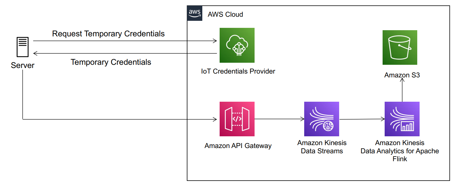


Amir Bar Or is a Principal Data Architect at AWS Professional Services. After 20 years leading software organizations and developing data analytics platforms and products, he is now sharing his experience with large enterprise customers and helping them scale their data analytics in the cloud.

Calculated fields, level-aware aggregations, and evaluation order in Amazon QuickSight

Post Syndicated from Ian Liao original https://aws.amazon.com/blogs/big-data/calculated-fields-level-aware-aggregations-and-evaluation-order-in-amazon-quicksight/

Amazon QuickSight is a fast, cloud-native, serverless, business intelligence service that makes it easy to deliver insights to everyone. QuickSight has carefully designed concepts and features that enable analysis builders, such as QuickSight authors, to design content-rich, interactive, and dynamic dashboards to share with dashboard viewers. As authors build an analysis, QuickSight transforms, filters, and aggregates data from tabular datasets into result sets to answer business questions. You can implement sophisticated data analytics in QuickSight in minutes by using calculated fields, then share within QuickSight in your organization, or embedded into apps or portals to share with thousands of users without any servers or infrastructure to set up.

This post gives you an end-to-end overview of how to perform various calculations in QuickSight and introduces you to the concepts of evaluation order and level-aware aggregation, which allow you to build more advanced analytics that use scalar, aggregate, and table functions. We also explain these approaches using an analogy to SQL.

This post assumes that you have a basic knowledge of analytics, SQL, and QuickSight.

Sample dataset and the business question

For this post, we use the Patient-Info dataset, which holds fictional transactional records for inpatient services. It contains dummy data that is randomly generated by AWS for demonstration purposes. The tabular table has the following columns:

  • Patient ID – ID of the patient
  • Admit Date – Date when the patient is admitted
  • Hospital – Name of the hospital
  • Service – Service item provided during inpatient visit
  • Category – Category of the service during inpatient visit
  • Subcategory – Subcategory of the service during inpatient visit
  • Revenue – Revenue from the service rendered
  • Profit – Profit from the service rendered

For instructions on creating a SPICE dataset in QuickSight with this dataset, see Prepare Data.

We use QuickSight to answer the following business question and variations of it from the dataset: What is the average profit ratio across all categories?

This question has a two-step calculation logic, which is common in use cases like goal completion analysis:

  1. Find the profit ratio per category.
  2. Find the average profit ratio across category.

In the process of answering this, we explore potential solutions in different approaches while discussing different features QuickSight has to offer:

  • Scalar functions – Return a single value computed for every row of input data, such as Plus, Division
  • Aggregation functions – Operate against a collection of values and return a single summarized value, such as Avg()
  • Table functions – Operate against a collection of rows and return a collection of rows, such as Rank(), avgOver(), sumOver()
  • Level-aware aggregation – A special type of table function that is evaluated before aggregation or before filtering

Some of these potential solutions don’t lead to the desired answer. But you will have a deep understanding of these QuickSight function types by thinking about why they don’t work. You can also jump to the definition of the calculated field Average Profit Ratio M to see the final solution.

Scalar functions

After the SPICE dataset is created with Patient-Info, let’s create an analysis from the dataset, and then try to find the answer to the business question using scalar functions.

  1. In the analysis editor, on the + Add menu, choose Add calculated field.

  1. In the calculated field editor, enter the name and formula:
Profit Ratio = profit / revenue
  1. Choose Save.

  1. Add Profit Ratio to a KPI visual. Remember to set the aggregate function to Average because we want to find the average profit ratio.

  1. Add category and Profit Ratio to a table visual. Again, we want to set the aggregate function to Average.

What is calculated here? Our dataset is at transactional level, so QuickSight calculates the profit ratio for every transaction and aggregates the results to the desired level defined in Visuals.

The calculation QuickSight has performed is similar to the following code:

select avg(profit/revenue)                                                                      
from dataset                -- to calculate the KPI visual         

select category, avg(profit/revenue)                                                            
from dataset                                                           
group by category                -- to calculate the table visual

This isn’t the answer we’re looking for because the profit ratio for a category is defined as the total profit of the category divided by the total revenue of the category.

Aggregate functions

Let’s try a different approach using aggregate functions:

Profit Ratio with Agg Func = sum(profit)/sum(revenue)

QuickSight is smart enough to figure out that author wants to aggregate data to the visual level first, and then use the division.

When we compare the results with Profit Ratio we created earlier, the numbers are quite different! This is because Profit Ratio calculates the transactional-level ratio first and then finds the average; whereas Profit Ratio with Agg Func calculates the category-level totals of the numerator and denominator first and then finds the ratio. Therefore, Profit Ratio is skewed by some big percentage loss in certain transactions, whereas Profit Ratio with Agg Func returns more meaningful data.

The calculation can be modeled in SQL as the following:

select category                                                                                   
, avg(profit/revenue) as "Profit Ratio"                          
, sum(profit)/sum(revenue) as "Profit Ratio with Agg Func"       
from dataset                                                      
group by category   

Profit Ratio with Agg Func returns the category-level profit ratio we wanted. The next step is to find an average of the ratios.

Table functions

Now let’s look for help from table functions. A table function outputs the same number of rows as input, and by default it has to be used on top of another aggregation function. To find the average of profit ratios, we can try avgOver():

avgOver of Profit Ratio = avgOver({Profit Ratio with Agg Func})

The following code is the corresponding SQL:

with aggregation_step as (                                                       
select category                                                  
, sum(profit)/sum(revenue) as "Profit Ratio with Agg Func"       
from dataset                                                     
group by category                                                 
),                                                                                                                                     
select category                                                  
, "Profit Ratio with Agg Func"                                    
, avg("Profit Ratio with Agg Func") over()                                                        
    as "avgOver of Profit Ratio"                                 
from aggregation_step

This example is complicated enough that QuickSight has to follow a sequence of steps to calculate a single visual. By default, QuickSight goes through up to six stages to complete the calculations for a visual:

  1. Simple calculations – Scalar calculations that can be applied before filter and aggregation
  2. Analysis filters – Apply filters on dimensions and measures with no aggregation option selected
  3. Top/bottom N filters – A special type of filter that is defined on a dimension, and sorted by a field that doesn’t contain table functions
  4. ON-VISUAL – Aggregations (evaluate group by and aggregations) and filters (apply filters with aggregation in the having clause)
  5. Table calculations – Calculate table functions and evaluate filters with table functions
  6. Totals and subtotals – Calculate totals and subtotals

With avgOver(), we’ve got the answer we’re looking for: 6.94%. However, the number is displayed for every category, which is not preferred. Actually, we can only get this number when the category is on the visual.

When the category is removed, Profit Ratio with Agg Func is aggregated to the grand total level in the aggregation step, therefore its avgOver remains the same number, as shown in the following screenshot.

To avoid these drawbacks, we need a new tool.

Level-aware aggregations

QuickSight introduced a type of calculation mechanism called level-aware aggregation (LAA) to meet more analytical requirements. Like table functions, LAAs operate against a collection of rows and return the same number of rows. Regular table functions can only be evaluated after the aggregation and filter stage in QuickSight. With LAA, authors can evaluate a group of functions before aggregations or even before filters.

The following diagram illustrates the evaluation order of LAA.

Because LAA is evaluated before aggregation, both its input and output are at the dataset level. Calculated fields with LAA behave similarly to calculated fields with scalar functions. It can be specified as a dimension or a measure. An aggregation function needs to be applied on top of LAA when the calculated field is used as a measure in visuals. When you want to filter on a calculated filed with LAA, QuickSight asks you to choose between no aggregation or one aggregation function. Also, duplicated rows are likely populated within the partition groups because the output level of LAA remains at the dataset level.

Let’s return to the business question: What is the average profit ratio across category?

It seems that we can use sumOver with category as the partition group, and then use average as the aggregate function to find the answer:

sumOver(profit) = sumOver(profit,[category],PRE_AGG)
sumOver(revenue) = sumOver(reveune,[category],PRE_AGG)
countOver(profit) = countOver(profit,[category],PRE_AGG)

Average Profit Ratio = avg({sumOver(profit)}/{sumOver(revenue)})

The following screenshot shows the aggregation functions defined for each measure. countOver(profit)with min() as aggregate simply returns transaction counts per category. It’s also the number of duplicated rows sumOver(profit) and sumOver(revenue) output.

8.12% is not the correct answer to the business question. The correct average should be 6.94%, as we saw earlier. How does QuickSight come up with the number?

For Average Profit Ratio, QuickSight tried to calculate the following:

with LAA as (
select category
, sum(profit) over (partition by category) as "sumOver(profit)"
, sum(revenue) over (partition by category) as "sumOver(revenue)"
, count(profit) over (partition by category) as "countOver(profit)"
from dataset 
),                       -- notice that LAA is at the same level of dataset

select category,
, avg("sumOver(profit)" / "sumOver(revenue)") as "Average Profit Ratio"
from LAA
group by category;       -- for data at category level

select avg("sumOver(profit)" / "sumOver(revenue)") as "Average Profit Ratio"
from LAA;                --  for data at total level

This is a smart approach. But each category has a different number of transactions, therefore each category-level Profit Ratio has a different number of duplicated rows. The average in the last step is equivalent to a weighted average of category-level Profit Ratio—weighted by the number of duplicates.

We want to modify Average Profit Ratio to offset the weights. We start with the following formula:

Average Profit Ratio M = Sum(Profit Ratio per Category)/number of Categories

We know the following:

Profit Ratio from LAA = sumOver(profit) / sumOver(revenue)
number of Categories = distinct_count(category)

How can we handle the duplicated rows? We can divide Profit Ratio by the number of duplicates before summing them up:

Sum(Profit Ratio per Category) = Sum(Profit Ratio from LAA / # of duplicate rows per Category)

# of duplicate rows per Category = countOver(profit)

Put them together, and we can create the following:

Average Profit Ratio M = sum( sumOver(profit) / sumOver(revenue) / countOver(profit) ) / distinct_count(category)

In this dataset, countOver(profit) are large numbers in which intermediate results may be dimmed to zero because they’re smaller than QuickSight’s precision, so we can add another factor 10000 to inflate intermediate results and deflate the final output:

Average Profit Ratio M = sum( 10000 * sumOver(profit) / sumOver(revenue) / countOver(profit) ) / distinct_count(category) / 10000

6.94% in total is what is expected!

For Average Profit Ratio M, QuickSight tried to calculate in the following steps:

with LAA as (
select category
, sum(profit) over (partition by category) as "sumOver(profit)"
, sum(revenue) over (partition by category) as "sumOver(revenue)"
, count(profit) over (partition by category) as "countOver(profit)"
from dataset 
),                       -- notice that LAA is at the same level of dataset

select category,
, sum(10000 * "sumOver(profit)" / "sumOver(revenue)" / "countOver(profit)") 
/ count(distinct category) / 10000 as "Average Profit Ratio"
from LAA
group by category;       -- for data at category level

select sum(10000 * "sumOver(profit)" / "sumOver(revenue)" / "countOver(profit)") 
/ count(distinct category) / 10000 as "Average Profit Ratio"
from LAA;                -- for data at total level

Conclusion

This post discussed how you can build powerful and complicated data analytics using QuickSight. We also used SQL-like scripts to help you better understand QuickSight concepts and features.

Thanks for reading!


About the Author

Ian Liao is a Data Visualization Engineer with the Data & Analytics Global Specialty Practice in AWS Professional Services.

Secure multi-tenant data ingestion pipelines with Amazon Kinesis Data Streams and Kinesis Data Analytics for Apache Flink

Post Syndicated from Abhinav Krishna Vadlapatla original https://aws.amazon.com/blogs/big-data/secure-multi-tenant-data-ingestion-pipelines-with-amazon-kinesis-data-streams-and-kinesis-data-analytics-for-apache-flink/

When designing multi-tenant streaming ingestion pipelines, there are myriad ways to design and build your streaming solution, each with its own set of trade-offs. The first decision you have to make is the strategy that determines how you choose to physically or logically separate one tenant’s data from another.

Sharing compute and storage resources helps reduce costs; however, it requires strong security measures to prevent cross-tenant data access. This strategy is known as a pool model. In contrast, a silo model helps reduce security complexity by having each tenant have its own set of isolated resources. However, this increases cost and operational overhead. A more detailed review of tenant isolation models is covered in the SaaS Storage Strategies whitepaper. In this post, we focus on the pool model to optimize for cost when supporting a multi-tenant streaming ingestion architecture.

Consider a retail industry data as a service (DaaS) company that ingests point of sale (POS) data from multiple customers and curates reports that blend sale transactions with third-party data in near-real time. The DaaS company can benefit from sharing compute and storage resources to reduce costs and stay competitive. For security, the DaaS company needs to authenticate each customer request and, to support a pool model, also needs to guarantee that data issues from one tenant don’t affect reports consumed by other customers. Similar scenarios apply to other industries that need to ingest data from semi-trusted servers. For example, in supply chain, a company could be streaming data from multiple suppliers to maintain a near-real-time status of SKUs and purchase orders. In the education industry, a third-party company could ingest data from servers at multiple schools and provide aggregated data to government agencies.

To build a multi-tenant streaming ingestion pipeline with shared resources, we walk you through an architecture that allows semi-trusted servers to use Amazon Kinesis Data Streams using the AWS IoT credentials provider feature for authentication, Amazon API Gateway as a proxy for authorization, and an Amazon Kinesis Data Analytics for Apache Flink application to aggregate and write data partitioned by the tenant in near-real time into an Amazon Simple Storage Service (Amazon S3) data lake. With this architecture, you remove the operational overhead of maintaining multiple Kinesis data streams (one per customer) and allow for cost optimization opportunities by performing better utilization of your provisioned Kinesis data stream shards.

The following architecture diagram illustrates the data ingestion pipeline.

In this architecture, authorized servers from one or multiple third-party companies send messages to an API Gateway endpoint. The endpoint puts messages into the proper partition of a shared Kinesis data stream. Finally, a Kinesis Data Analytics consumer application aggregates, compresses, and writes data into the proper partition of an S3 data lake.

The following sections describe in more detail the multi-tenant architecture considerations and implementation details for this architecture.

Authentication

First, you need to decide on the desired authentication mechanisms. To simplify onboarding new customers and eliminate the need for hardcoded credentials on customers servers, we recommend looking into the credentials provider feature of AWS IoT. Each tenant can use a provisioned x.509 certificate to securely retrieve temporary credentials and authenticate against AWS services using an AWS Identity and Access Management (IAM) role. For more information on how this works, see How to Eliminate the Need for Hardcoded AWS Credentials in Devices by Using the AWS IoT Credentials Provider.

For additional authentication mechanisms directly with API Gateway, see Controlling and managing access to a REST API in API Gateway.

Authorization

After you’re authenticated with IAM, the next step is authorization. Simply put, make sure each tenant can only write to their respective data lake partition. One of the key risks to mitigate in a multi-tenant steaming ingestion workflow is the scenario where a tenant server is compromised and it attempts to impersonate other tenants sending bogus data. To guarantee isolation of data ingest and reduce the blast radius of bad data, you could consider the following options:

  • Use a silo model and provision one Kinesis data stream per tenant – Kinesis Data Streams provides access control at the stream level. This approach provides you with complete isolation and the ability to scale your stream capacity up or down on a per-tenant basis. However, there is operational overhead in maintaining multiple streams, and optimizing for cost has limitations. Each data stream is provisioned by increments of one shard or 1 MB/sec of ingestion capacity with up to 1,000 PUT records per second. Pricing is based on shards per hour. One shard could be well beyond your tenant requirements and tenant onboarding costs could scale rapidly.
  • Use AWS IoT Core with one topic per tenant using topic filters and an AWS IoT rule to push data into a shared data stream – AWS IoT Core gives access control at the topic level. Each tenant can send data to only their respective topic (for example, tenantID topic) based on their IAM credentials. We can then use an AWS IoT rule to extract the tenantID from the topic and push data into a shared data stream using tenantID as the partition key.
  • Use API Gateway as a proxy with mapping templates and a shared data stream – Kinesis Data Streams doesn’t provide access control at the data partition level. However, API Gateway provides access control at the method and path level. With API Gateway as a proxy, you can use mapping templates to programmatically fetch the tenant UUID from the path and set it as the partition key before pushing the data to Kinesis Data Streams.

Optimize for costs

The last two preceding options use a pool model and share a single Kinesis data stream to reduce operational overhead and costs. To optimize costs even further, you need to consider the pricing model of each of these services (API Gateway vs. AWS IoT Core) and three factors in your use case: the average size for each message, the rate at which the data is being ingested, and the data latency requirements.

Consider an example where you have 1,000 tenants (devices) and each produces data at the rate of one request per second with an average payload of 8 KB. AWS IoT Core is priced per million messages and per million rules. Each message is metered at 5 KB increments, so you’re charged for two messages per payload. If you have small payloads and very low latency requirements, AWS IoT Core is likely your best choice. If you can introduce some latency and buffer your messages at each tenant, then API Gateway is your best option because the pricing model for REST APIs requests is on a per-API call basis and not metered by KB. You can use the AWS Pricing Calculator to quickly decide which option offers the best price for your use case.

For example, with API Gateway, you can optimize your cost even further by reducing the number of API requests. Instead of each tenant sending 8 KB of data per second, you can send 240 KB every 30 seconds and reduce costs considerably. We can explore a sample cost calculation for API Gateway considering this scenario: average size of message: 240 KB, REST API request units per month: 2 request per minute x 60 min x 24 hrs. x 30 days = 86,400 requests x 1,000 tenants = 86,400,000.

The following sections walk you through the configuration of API Gateway and Kinesis to prevent cross-data access when you support a multi-tenant streaming ingestion pipeline architecture.

Enable API Gateway as a Kinesis Data Streams proxy

API Gateway is a fully managed service that makes it easy for developers to publish, maintain, monitor, and secure APIs at any scale. You can create an API Gateway endpoint to expose other AWS services, such as Amazon Simple Notification Service (Amazon SNS), Amazon S3, Kinesis, and even AWS Lambda. All AWS services support dedicated APIs to expose their features. However, the application protocols or programming interfaces are likely to differ from service to service. An API Gateway API with the AWS integration has the advantage of providing a consistent application protocol for your client to access different AWS services. In our use case, we use API Gateway as a proxy to Kinesis in order to handle IAM authentication and authorize clients to invoke URL paths with their unique tenant ID. API Gateway has additional features that are beneficial for multi-tenant applications, like rate limiting API calls per tenant, requests and response transformations, logging and monitoring, and more.

When you configure API Gateway with IAM resource-level permissions, you can make sure each tenant can only make requests to a unique URL path. For example, if the tenant invokes the API Gateway URL with their tenant ID in the path (for example, https://api-id.execute-api.us-east-2.amazonaws.com/{tenantId}), IAM validates that the tenant is authorized to invoke this URL only. For more details on how to set up an IAM policy to a specific API Gateway URL path, see Control access for invoking an API.

Then, to ensure no authorized customer can impersonate other tenant by sending bogus data, API Gateway extracts the tenant ID from the URL path programmatically using the API Gateway mapping template feature. API Gateway allows developers to transform payloads before passing it to backend resources using mapping templates written with JSONPath expressions. With this feature, we can extract the tenant ID from the URL and pass it as the partition key of the shared data stream. The following is a sample mapping template:

{
    "StreamName": "$input.params('stream-name')",
    "Data": "$util.base64Encode($input.json('$.Data'))",
    "PartitionKey": "$input.params('partition')"
}

In the preceding code, partition is the parameter name you specify in your API Gateway resource path. The following screenshot shows what the configuration looks like on the API Gateway console.

After messages in the data stream use the proper partition, the next step is to transform, enrich, and aggregate messages before writing them into an S3 data lake. For this workflow, we use Kinesis Data Analytics for Apache Flink to have full control of the data lake partition configuration. The following section describes the approach to ensure data is written in the proper partition.

Use Kinesis Data Analytics for Apache Flink to process and write data into an S3 data lake

After we guarantee that messages within the data stream have the right tenant ID as the partition key, we can use Kinesis Data Analytics for Apache Flink to continuously process messages in near-real time and store them in Amazon S3. Kinesis Data Analytics for Apache Flink is an easy way to transform and analyze streaming data in real time. Apache Flink is an open-source framework and engine for processing data streams. Kinesis Data Analytics reduces the complexity of building, managing, and integrating Apache Flink applications with other AWS services. Because this solution is also serverless, there are no servers to manage, it scales automatically to match the volume and throughput of your incoming data, and you only pay for the resources your streaming applications consume.

In this scenario, we want to extract the partition key (tenantId) from each Kinesis data stream message, then process all messages within a time window and use the tenant ID as the file prefix of the files we write into the destination S3 bucket. In other words, we write the data into the proper tenant partition. The result writes data in files that look like the following:

s3://mybucket/year=2020/month=1/day=1/tenant=A01/part-0-0
s3://mybucket/year=2020/month=1/day=1/tenant=A02/part-0-1
s3://mybucket/year=2020/month=1/day=1/tenant=A03/part-0-3

To achieve this, we need to implement two custom classes within the Apache Flink application code.

First, we use a custom deserializer class to extract the partition key from the data stream and append it to the body of the message. We can achieve this by overriding the deserialize method of the KinesisDeserializationSchema class:

class CustomKinesisDeserializer implements  KinesisDeserializationSchema<String> {
    private static final Logger log = LogManager.getLogger(CustomKinesisDeserializer.class);
   @Override
    public String deserialize(byte[] bytes, String partitionKey, String seqNum,
                              long approxArrivalTimeStamp, String stream, String shardId) throws IOException {
        log.debug("deserialize - enter");
        String s = new String(bytes);
        JSONObject json = new JSONObject(s);
        json.put("tenantid", partitionKey);
        return json.toString();
    }
    @Override
    public TypeInformation<String> getProducedType() {
        return BasicTypeInfo.STRING_TYPE_INFO;
    }
}

Next, we use a customBucketAssignerclass to use the partition key in the body of the message (in our case, the tenant ID) as the bucket prefix:

private static final BucketAssigner<String, String> assigner = new BucketAssigner<String, String> () {

        @Override
        public String getBucketId(String element, BucketAssigner.Context context) {
            log.debug("getBucketId - enter");
            JSONObject json = new JSONObject(element);
            if (json.has("tenantid")) {
                String tenantId = json.getString("tenantid");
                return "tenantid=" + tenantId;
            }
            return "tenantid=unknown";
        }

        @Override
        public SimpleVersionedSerializer<String> getSerializer() {
            return SimpleVersionedStringSerializer.INSTANCE;
        }
};

The following code is the full sample class for the Kinesis Data Analytics with Apache Flink application. The purpose of the sample code is to illustrate how you can obtain the partition key from the data stream and use it as your bucket prefix via the BucketAssigner class. Your implementation might require additional windowing logic to enrich, aggregate, and transform your data before writing it into an S3 bucket. In this post, we write data into a tenantId partition, but your code might require additional partition fields (such as by date). For additional code examples, see Kinesis Data Analytics for Apache Flink: Examples.

package com.amazonaws.services.kinesisanalytics;

import com.amazonaws.services.kinesisanalytics.runtime.KinesisAnalyticsRuntime;
import org.apache.flink.api.common.serialization.SimpleStringEncoder;
import org.apache.flink.api.common.typeinfo.TypeInformation;
import org.apache.flink.core.fs.Path;
import org.apache.flink.core.io.SimpleVersionedSerializer;
import org.apache.flink.streaming.api.datastream.DataStream;
import org.apache.flink.streaming.api.environment.StreamExecutionEnvironment;
import org.apache.flink.streaming.api.functions.sink.filesystem.BucketAssigner;
import org.apache.flink.streaming.api.functions.sink.filesystem.StreamingFileSink;
import org.apache.flink.streaming.api.functions.sink.filesystem.bucketassigners.SimpleVersionedStringSerializer;
import org.apache.flink.streaming.connectors.kinesis.FlinkKinesisConsumer;
import org.apache.flink.streaming.connectors.kinesis.config.ConsumerConfigConstants;
import org.apache.flink.streaming.connectors.kinesis.serialization.KinesisDeserializationSchema;
import org.apache.logging.log4j.LogManager;
import org.apache.logging.log4j.Logger;
import org.json.JSONObject;

import java.io.IOException;
import java.util.Map;
import java.util.Properties;

public class S3StreamingSinkWithPartitionsJob {

    private static final Logger log = LogManager.getLogger(S3StreamingSinkWithPartitionsJob.class);
    private static String s3SinkPath;
    private static String inputStreamName;
    private static String region;

    /**
     * Custom BucketAssigner to specify the bucket path/prefix with the Kinesis Stream partitionKey.
     *
     * Sample code. Running application with debug mode with this implementation will expose data into log files
     */
    private static final BucketAssigner<String, String> assigner = new BucketAssigner<String, String> () {

        @Override
        public String getBucketId(String element, BucketAssigner.Context context) {
            log.debug("getBucketId - enter");
            JSONObject json = new JSONObject(element);
            if (json.has("tenantid")) {
                String tenantId = json.getString("tenantid");
                return "tenantid=" + tenantId;
            }
            return "tenantid=unknown";
        }

        @Override
        public SimpleVersionedSerializer<String> getSerializer() {
            return SimpleVersionedStringSerializer.INSTANCE;
        }
    };


    private static DataStream<String> createSourceFromStaticConfig(StreamExecutionEnvironment env) throws IOException {
        log.debug("createSourceFromStaticConfig - enter - variables: {region:" + region +
                ", inputStreamName:" + inputStreamName + "}");
        Properties inputProperties = new Properties();
        inputProperties.setProperty(ConsumerConfigConstants.AWS_REGION, region);
        inputProperties.setProperty(ConsumerConfigConstants.STREAM_INITIAL_POSITION, "LATEST");

        /*
         * Implementinga custom serializer class that extends KinesisDeserializationSchema interface
         * to get additional values from partition keys.
         */
        return env.addSource(new FlinkKinesisConsumer<>(inputStreamName,
                new CustomKinesisDeserializer(),
                inputProperties
        ));
    }

    private static StreamingFileSink<String> createS3SinkFromStaticConfig() {
        log.debug("createS3SinkFromStaticConfig - enter - variables: { s3SinkPath:" + s3SinkPath + "}");
        final StreamingFileSink<String> sink = StreamingFileSink
                .forRowFormat(new Path(s3SinkPath), new SimpleStringEncoder<String>("UTF-8"))
                .withBucketAssigner(assigner)
                .build();
        return sink;
    }

    public static void main(String[] args) throws Exception {

        Map<String, Properties> applicationProperties = KinesisAnalyticsRuntime.getApplicationProperties();
        Properties consumerProperties = applicationProperties.get("ConsumerConfigProperties");
        region = consumerProperties.getProperty("Region","us-west-2");
        inputStreamName = consumerProperties.getProperty("InputStreamName");
        s3SinkPath = "s3a://" + consumerProperties.getProperty("S3SinkPath") + "/data";

        final StreamExecutionEnvironment env = StreamExecutionEnvironment.getExecutionEnvironment();
        DataStream<String> input = createSourceFromStaticConfig(env);
        input.addSink(createS3SinkFromStaticConfig());
        env.execute("Flink S3 Streaming with Partitions Sink Job");
    }

}

/**
 * Custom deserializer to pass partitionKey from KDS into the record value. The partition key can be used
 * by the bucket assigner to leverage it as the s3 path/prefix/partition.
 *
 * Sample code. Running application with debug mode with this implementation will expose data into log files
 */

class CustomKinesisDeserializer implements  KinesisDeserializationSchema<String> {

    private static final Logger log = LogManager.getLogger(CustomKinesisDeserializer.class);

    @Override
    public String deserialize(byte[] bytes, String partitionKey, String seqNum,
                              long approxArrivalTimeStamp, String stream, String shardId) throws IOException {
        log.debug("deserialize - enter");
        String s = new String(bytes);
        JSONObject json = new JSONObject(s);
        json.put("tenantid", partitionKey);
        return json.toString();
    }

    @Override
    public TypeInformation<String> getProducedType() {
        return TypeInformation.of(String.class);
    }

}

To test and build this multi-tenant stream ingestion pipeline, you can deploy an AWS CloudFormation template in your AWS environment. The following section provides step-by-step instructions on how to deploy and test the sample template.

Deploy a sample multi-tenant streaming ingestion pipeline

AWS CloudFormation simplifies provisioning and managing infrastructure and services on AWS via JSON or .yaml templates. Follow these instructions to deploy and test the sample workflow described in this post. The instructions assume a basic understanding of AWS Cloud concepts, the AWS Management Console, and working with REST APIs.

  1. Create a destination S3 bucket.
  2. Deploy the CloudFormation template.

The template has only been tested in the us-west-2 Region, and creates IAM roles and users with limited access scope. This template doesn’t register CA certificates or implement the AWS IoT credentials provider feature for authentication. To test the pipeline, the template creates an IAM user for authentication with API Gateway. If you want to test the AWS IoT credentials provider feature with this implementation, follow the instructions in How to Eliminate the Need for Hardcoded AWS Credentials in Devices by Using the AWS IoT Credentials Provider.

  1. For Stack name¸ enter a name (for example, flinkapp).
  2. For KDAS3DestinationBucket, enter the name of the S3 bucket you created.
  3. Leave the other parameters as default.

  1. Accept all other options, including acknowledging the template will create IAM principals on your behalf.
  2. Wait until the stack shows the status CREATE_COMPLETE.

Now you can start your Kinesis Data Analytics for Apache Flink application.

  1. On the Kinesis Data Analytics console, choose Analytics applications.
  2. Select the application that starts with KinesisAnalyticsFI_*.
  3. Choose Run.

  1. Choose Run without snapshot.
  2. Wait for the application to show the status Running.

Now you can test sending messages to your API Gateway endpoint. Remember requests should be authenticated. The CloudFormation template created an IAM test user for this purpose. We recommend using a development API tool for this step. For this post, we use Postman.

  1. On the AWS CloudFormation console, navigate to the Outputs tab of your stack.
  2. Note the API Gateway endpoint (InvokeURL) and the name of the IAM test user.

  1. Create and retrieve the access key and secret key of your test user. For instructions, see Programmatic access.

AWS recommends using temporary keys when authenticating requests to AWS services. For testing purposes, we use a long-lived access key from this limited scope test user.

  1. Use your API development tool to build a POST request to your API Gateway endpoint using your IAM test user secrets.

The following screenshot shows the Authorization tab of the request using Postman.

The following screenshot shows the Body tab of the request using Postman.

  1. For the body of the request, you can use the following payload:
{
    Data: {
        "key1": "value1",
        "key2": "value2",
        "key3": "value3"
    }
}

You should get a response from the data stream that looks as follows:

{
 "EncryptionType": "KMS",
 "SequenceNumber": "49619151594519161991565402527623825830782609999622307842",
 "ShardId": "shardId-000000000000"
}

  1. Try to make a request to a different tenant by changing the path from /prod/T001 to /prod/T002.

Because the user isn’t authorized to send data to this endpoint, you get the following error message:

{
    "Message": "User: arn:aws:iam::*******4205:user/flinkapp-MultiTenantStreamTestUser-EWUSMWR0T5I5 is not authorized to perform: execute-api:Invoke on resource: arn:aws:execute-api:us-west-2:********4205:fktw02penb/prod/POST/T002"
}

  1. Browse to your destination S3 bucket.

You should be able to see a new file within your T001 tenant’s folder or partition.

  1. Download and open your file (part-*-*).

The content should look like the following data (in this scenario, we made six requests to the tenant’s API Gateway endpoint):

{"key1":"value1","key2":"value2","key3":"value3","tenantid":"T001"}

Clean up

After you finalize your testing, delete the CloudFormation stack and any data written into your destination S3 bucket to prevent incurring unnecessary charges.

Conclusion

Sharing resources in multi-tenant architectures allows organizations to optimize for costs while providing controls for proper tenant isolation and security. In this post, we showed you how to use API Gateway as a proxy to authorize tenants to a specific partition in your shared Kinesis data stream and prevent cross-tenant data access when performing data ingestion from semi-trusted servers. We also showed you how buffering data and sharing a single data stream with multiple tenants reduces operational overhead and optimizes for costs by taking advantage of better resource utilization. Check out the Kinesis Data Streams and Kinesis Data Analytics quick starts to evaluate them for your multi-tenant ingestion use case.


About the Authors

Abhinav Krishna Vadlapatla is a Solutions Architect with Amazon Web Services. He supports startups and small businesses with their cloud adoption to build scalable and secure solutions using AWS. In his free time, he likes to cook and travel.


Pablo Redondo Sanchez is a Senior Solutions Architect at Amazon Web Services. He is a data enthusiast and works with customers to help them achieve better insights and faster outcomes from their data analytics workflows. In his spare time, Pablo enjoys woodworking and spending time outdoor with his family in Northern California.

Query a Teradata database using Amazon Athena Federated Query and join with data in your Amazon S3 data lake

Post Syndicated from Navnit Shukla original https://aws.amazon.com/blogs/big-data/query-a-teradata-database-using-amazon-athena-federated-query-and-join-with-data-in-your-amazon-s3-data-lake/

If you use data lakes in Amazon Simple Storage Service (Amazon S3) and use Teradata as your transactional data store, you may need to join the data in your data lake with Teradata in the cloud, Teradata running on Amazon Elastic Compute Cloud (Amazon EC2), or with an on-premises Teradata database, for example to build a dashboard or create consolidated reporting.

In these use cases, the Amazon Athena Federated Query feature allows you to seamlessly access the data from Teradata database without having to move the data to your S3 data lake. This removes the overhead in managing such jobs.

In this post, we will walk you through a step-by-step configuration to set up Athena Federated Query using AWS Lambda to access data in a Teradata database running on premises.

For this post, we will be using the Oracle Athena Federated Query connector developed by Trianz. The runtime includes a Teradata instance on premises. Your Teradata instance can be on the cloud, on Amazon EC2, or on premises. You can deploy the Trianz Oracle Athena Federated Query connector from the AWS Serverless Application Repository.

Let’s start with discussing the solution and then detailing the steps involved.

Solution overview

Data federation is the capability to integrate data in another data store using a single interface (Athena). The following diagram depicts how Athena Federated Query works by using Lambda to integrate with a federated data source.

Athena is an interactive query service that makes it easy to analyze data in Amazon S3 using standard SQL. If you have data in sources other than Amazon S3, you can use Athena Federated Query to query the data in place or build pipelines to extract data from multiple data sources and store them in Amazon S3. With Athena Federated Query, you can run SQL queries across data stored in relational, non-relational, object, and custom data sources.

When a federated query is run, Athena identifies the parts of the query that should be routed to the data source connector and executes them with Lambda. The data source connector makes the connection to the source, runs the query, and returns the results to Athena. If the data doesn’t fit into Lambda RAM runtime memory, it spills the data to Amazon S3 and is later accessed by Athena.

Athena uses data source connectors which internally use Lambda to run federated queries. Data source connectors are pre-built and can be deployed from the Athena console or from the Serverless Application Repository. Based on the user submitting the query, connectors can provide or restrict access to specific data elements.

To implement this solution, we complete the following steps:

  1. Create a secret for the Teradata instance using AWS Secrets Manager.
  2. Create an S3 bucket and subfolder for Lambda to use.
  3. Configure Athena federation with the Teradata instance.
  4. Run federated queries with Athena.

Prerequisite

Before you start this walkthrough, make sure your Teradata database is up and running.

Create a secret for the Teradata instance

Our first step is to create a secret for the Teradata instance with a username and password using Secrets Manager.

  1. On the Secrets Manager console, choose Secrets.
  2. Choose Store a new secret.
  3. Select Other types of secrets.
  4. Set the credentials as key-value pairs (username, password) for your Teradata instance.

  1. For Secret name, enter a name for your secret. Use the prefix TeradataAFQ so it’s easy to find.
  2. Leave the remaining fields at their defaults and choose Next.
  3. Complete your secret creation.

Set up your S3 bucket for Lambda

On the Amazon S3 console, create a new S3 bucket and subfolder for Lambda to use. For this post, we create athena-accelerator/teradata.

Configure Athena federation with the Teradata instance

To configure Athena federation with Teradata instance, complete the following steps:

  1. On the AWS Serverless Application Repository console, choose Available applications.
  2. Select Show apps that create custom IAM roles or resource policies.
  3. In the search field, enter TrianzTeradataAthenaJDBC.
  4. Choose the application.

  1. For SecretNamePrefix, enter TeradataAFQ.
  2. For SpillBucket, enter Athena-accelerator/teradata.
  3. For JDBCConnectorConfig, use the format teradata://jdbc:teradata://hostname/user=testUser&password=testPassword.
  4. For DisableSpillEncryption, enter false.
  5. For LambdaFunctionName, enter teradataconnector.
  6. For SecurityGroupID, enter the security group ID where the Teradata instance is deployed.

Make sure to apply valid inbound and outbound rules based on your connection.

  1. For SpillPrefix, create a folder under the S3 bucket you created and specify the name (for example, athena-spill).
  2. For Subnetids, use the subnets where the Teradata instance is running with comma separation.

Make sure the subnet is in a VPC and has NAT gateway and internet gateway attached.

  1. Select the I acknowledge check box.
  2. Choose Deploy.

Make sure that the AWS Identity and Access Management (IAM) roles have permissions to access AWS Serverless Application Repository, AWS CloudFormation, Amazon S3, Amazon CloudWatch, Amazon CloudTrail, Secrets Manager, Lambda, and Athena. For more information about Athena IAM access, see Example IAM Permissions Policies to Allow Athena Federated Query.

Run federated queries with Athena

Run your queries using lambda:teradataconnector to run against tables in the Teradata database. teradataconnector is the name of lambda function which we have created in step 7 of previous section of this blog.

lambda:teradataconnector references a data source connector Lambda function using the format lambda:MyLambdaFunctionName. For more information, see Writing Federated Queries.

The following screenshot shows the query that joins the dataset between Teradata and the S3 data lake.

Key performance best practices

If you’re considering Athena Federated Query with Teradata, we recommend the following best practices:

  • Athena Federated query works great for queries with predicate filtering because the predicates are pushed down to the Teradata database. Use filter and limited-range scans in your queries to avoid full table scans.
  • If your SQL query requires returning a large volume of data from the Teradata database to Athena (which could lead to query timeouts or slow performance), you may consider moving data from Teradata to your S3 data lake.
  • The star schema is a commonly used data model in Teradata. In the star schema model, unload your large fact tables into your S3 data lake and leave the dimension tables in Teradata. If large dimension tables are contributing to slow performance or query timeouts, unload those tables to your S3 data lake.
  • When you run federated queries, Athena spins up multiple Lambda functions, which causes a spike in database connections. It’s important to monitor the Teradata database WLM queue slots to ensure there is no queuing. Additionally, you can use concurrency scaling on your Teradata database cluster to benefit from concurrent connections to queue up.

Conclusion

In this post, you learned how to configure and use Athena Federated Query with Teradata. Now you don’t need to wait for all the data in your Teradata data warehouse to be unloaded to Amazon S3 and maintained on a day-to-day basis to run your queries.

You can use the best practices outlined in the post to help minimize the data transferred from Teradata for better performance. When queries are well written for Athena Federated Query, the performance penalties are negligible.

For more information, see the Athena User Guide and Using Amazon Athena Federated Query.


About the Author

Navnit Shukla is an AWS Specialist Solution Architect in Analytics. He is passionate about helping customers uncover insights from their data. He has been building solutions to help organizations make data-driven decisions.

Query an Apache Hudi dataset in an Amazon S3 data lake with Amazon Athena part 1: Read-optimized queries

Post Syndicated from Dhiraj Thakur original https://aws.amazon.com/blogs/big-data/part-1-query-an-apache-hudi-dataset-in-an-amazon-s3-data-lake-with-amazon-athena-part-1-read-optimized-queries/

On July 16, 2021, Amazon Athena upgraded its Apache Hudi integration with new features and support for Hudi’s latest 0.8.0 release. Hudi is an open-source storage management framework that provides incremental data processing primitives for Hadoop-compatible data lakes. This upgraded integration adds the latest community improvements to Hudi along with important new features including snapshot queries, which provide near real-time views of table data, and reading bootstrapped tables which provide efficient migration of existing table data.

In this series of posts on Athena and Hudi, we will provide a short overview of key Hudi capabilities along with detailed procedures for using read-optimized queries, snapshot queries, and bootstrapped tables.

Overview

With Apache Hudi, you can perform record-level inserts, updates, and deletes on Amazon S3, allowing you to comply with data privacy laws, consume real-time streams and change data captures, reinstate late-arriving data, and track history and rollbacks in an open, vendor neutral format. Apache Hudi uses Apache Parquet and Apache Avro storage formats for data storage, and includes built-in integrations with Apache Spark, Apache Hive, and Apache Presto, which enables you to query Apache Hudi datasets using the same tools that you use today with near-real-time access to fresh data.

An Apache Hudi dataset can be one of the following table types:

  • Copy on Write (CoW) – Data is stored in columnar format (Parquet), and each update creates a new version of the base file on a write commit. A CoW table type typically lends itself to read-heavy workloads on data that changes less frequently.
  • Merge on Read (MoR) – Data is stored using a combination of columnar (Parquet) and row-based (Avro) formats. Updates are logged to row-based delta files and are compacted as needed to create new versions of the columnar files. A MoR table type is typically suited for write-heavy or change-heavy workloads with fewer reads.

Apache Hudi provides three logical views for accessing data:

  • Read-optimized – Provides the latest committed dataset from CoW tables and the latest compacted dataset from MoR tables
  • Incremental – Provides a change stream between two actions out of a CoW dataset to feed downstream jobs and extract, transform, load (ETL) workflows
  • Real-time – Provides the latest committed data from a MoR table by merging the columnar and row-based files inline

As of this writing, Athena supports read-optimized and real-time views.

Using read-optimized queries

In this post, you will use Athena to query an Apache Hudi read-optimized view on data residing in Amazon S3. The walkthrough includes the following high-level steps:

  1. Store raw data in an S3 data lake.
  2. Transform the raw data to Apache Hudi CoW and MoR tables using Apache Spark on Amazon EMR.
  3. Query and analyze the tables on Amazon S3 with Athena on a read-optimized view.
  4. Perform an update to a row in the Apache Hudi dataset.
  5. Query and analyze the updated dataset using Athena.

Architecture

The following diagram illustrates our solution architecture.

In this architecture, you have high-velocity weather data stored in an S3 data lake. This raw dataset is processed on Amazon EMR and stored in an Apache Hudi dataset in Amazon S3 for further analysis by Athena. If the data is updated, Apache Hudi performs an update on the existing record, and these updates are reflected in the results fetched by the Athena query.

Let’s build this architecture.

Prerequisites

Before getting started, we set up our resources. For this post, we use the us-east-1 Region.

  1. Create an Amazon Elastic Compute Cloud (Amazon EC2) key pair. For instructions, see Create a key pair using Amazon EC2.
  2. Create a S3 bucket for storing the raw weather data (for this post, we call it weather-raw-bucket).
  3. Create two folders in the S3 bucket: parquet_file and delta_parquet.
  4. Download all the data files, Apache Scala scripts (data_insertion_cow_delta_script, data_insertion_cow_script, data_insertion_mor_delta_script, and data_insertion_mor_script), and Athena DDL code (athena_weather_hudi_cow.sql and athena_weather_hudi_mor.sql) from the GitHub repo.
  5. Upload the weather_oct_2020.parquet file to weather-raw-bucket/parquet_file.
  6. Upload the file weather_delta.parquet to weather-raw-bucket/delta_parquet. We update an existing weather record from a relative_humidity of 81 to 50 and a temperature of 6.4 to 10.
  7. Create another S3 bucket for storing the Apache Hudi dataset. For this post, we create a bucket with a corresponding subfolder named athena-hudi-bucket/hudi_weather.
  8. Deploy the EMR cluster using the provided AWS CloudFormation template:
  9. Enter a name for your stack.
  10. Choose a pre-created key pair name.

This is required to connect to the EMR cluster nodes. For more information, see Connect to the Master Node Using SSH.

  1. Accept all the defaults and choose Next.
  2. Acknowledge that AWS CloudFormation might create AWS Identity and Access Management (IAM) resources.
  3. Choose Create stack.

Use Apache Hudi with Amazon EMR

When the cluster is ready, you can use the provided key pair to SSH into the primary node.

  1. Use the following bash command to load the spark-shell to work with Apache Hudi:
    spark-shell --conf "spark.serializer=org.apache.spark.serializer.KryoSerializer" --conf "spark.sql.hive.convertMetastoreParquet=false" --jars /usr/lib/hudi/hudi-spark-bundle.jar,/usr/lib/spark/external/lib/spark-avro.jar

  2. On the spark-shell, run the following Scala code in the script data_insertion_cow_script to import weather data from the S3 data lake to an Apache Hudi dataset using the CoW storage type:
    import org.apache.spark.sql.SaveMode
    import org.apache.spark.sql.functions._
    import org.apache.hudi.DataSourceWriteOptions
    import org.apache.hudi.config.HoodieWriteConfig
    import org.apache.hudi.hive.MultiPartKeysValueExtractor
    
    //Set up various input values as variables
    val inputDataPath = "s3://weather-raw-bucket/parquet_file/"
    val hudiTableName = "weather_hudi_cow"
    val hudiTablePath = "s3://athena-hudi-bucket/hudi_weather/" + hudiTableName
    
    // Set up our Hudi Data Source Options
    val hudiOptions = Map[String,String](
        DataSourceWriteOptions.RECORDKEY_FIELD_OPT_KEY -> "city_id",
    	DataSourceWriteOptions.RECORDKEY_FIELD_OPT_KEY -> "timestamp",
        DataSourceWriteOptions.PARTITIONPATH_FIELD_OPT_KEY -> "date", 
        HoodieWriteConfig.TABLE_NAME -> hudiTableName, 
        DataSourceWriteOptions.OPERATION_OPT_KEY ->
            DataSourceWriteOptions.INSERT_OPERATION_OPT_VAL, 
        DataSourceWriteOptions.PRECOMBINE_FIELD_OPT_KEY -> "timestamp", 
        DataSourceWriteOptions.HIVE_SYNC_ENABLED_OPT_KEY -> "true", 
        DataSourceWriteOptions.HIVE_TABLE_OPT_KEY -> hudiTableName, 
        DataSourceWriteOptions.HIVE_PARTITION_FIELDS_OPT_KEY -> "date", 
        DataSourceWriteOptions.HIVE_PARTITION_EXTRACTOR_CLASS_OPT_KEY ->
            classOf[MultiPartKeysValueExtractor].getName)
    
    // Read data from S3 and create a DataFrame with Partition and Record Key
    val inputDF = spark.read.format("parquet").load(inputDataPath)
    
    // Write data into the Hudi dataset
    inputDF.write.format("org.apache.hudi").options(hudiOptions).mode(SaveMode.Append).save(hudiTablePath)

Replace the S3 bucket path for inputDataPath and hudiTablePath in the preceding code with your S3 bucket.

For more information about DataSourceWriteOptions, see Work with a Hudi Dataset.

  1. In the spark-shell, count the total number of records in the Apache Hudi dataset:
    scala> inputDF.count()
    res1: Long = 1000

  2. Repeat the same step for creating an MoR table using data_insertion_mor_script (the default is COPY_ON_WRITE).
  3. Run the spark.sql("show tables").show(); query to list three tables, one for CoW and two queries, _rt and _ro, for MoR.

The following screenshot shows our output.

Let’s check the processed Apache Hudi dataset in the S3 data lake.

  1. On the Amazon S3 console, confirm the subfolders weather_hudi_cow and weather_hudi_mor are in athena-hudi-bucket.
  1. Navigate to the weather_hudi_cow subfolder to see the Apache Hudi dataset that is partitioned using the date key—one for each date in our dataset.
  2. On the Athena console, create a hudi_athena_test database using following command:
    create database hudi_athena_test;

You use this database to create all your tables.

  1. Create an Athena table using the athena_weather_hudi_cow.sql script:
    CREATE EXTERNAL TABLE weather_partition_cow(
      `_hoodie_commit_time` string,
      `_hoodie_commit_seqno` string,
      `_hoodie_record_key` string,
      `_hoodie_partition_path` string,
      `_hoodie_file_name` string,
      `city_id` string,
      `timestamp` string,
      `relative_humidity` decimal(3,1),
      `temperature` decimal(3,1),
      `absolute_humidity` decimal(5,4)
      )
      PARTITIONED BY ( 
      `date` string)
    ROW FORMAT SERDE
      'org.apache.hadoop.hive.ql.io.parquet.serde.ParquetHiveSerDe'
    STORED AS INPUTFORMAT
      'org.apache.hudi.hadoop.HoodieParquetInputFormat'
    OUTPUTFORMAT
      'org.apache.hadoop.hive.ql.io.parquet.MapredParquetOutputFormat'
    LOCATION
      's3://athena-hudi-bucket/hudi_weather/weather_hudi_cow'
    

Replace the S3 bucket path in the preceding code with your S3 bucket (Hudi table path) in LOCATION.

  1. Add partitions to the table by running the following query from the athena_weather_judi_cow.sql script on the Athena console:
    ALTER TABLE weather_partition_cow ADD
    PARTITION (date = '2020-10-01') LOCATION 's3://athena-hudi-bucket/hudi_weather/weather_hudi_cow/2020-10-01/'
    PARTITION (date = '2020-10-02') LOCATION 's3://athena-hudi-bucket/hudi_weather/weather_hudi_cow/2020-10-02/'
    PARTITION (date = '2020-10-03') LOCATION 's3://athena-hudi-bucket/hudi_weather/weather_hudi_cow/2020-10-03/'
    PARTITION (date = '2020-10-04') LOCATION 's3://athena-hudi-bucket/hudi_weather/weather_hudi_cow/2020-10-04/';

Replace the S3 bucket path in the preceding code with your S3 bucket (Hudi table path) in LOCATION.

  1. Confirm the total number of records in the Apache Hudi dataset with the following query:
    SELECT count(*) FROM "hudi_athena_test"."weather_partition_cow";

It should return a single row with a count of 1,000.

Now let’s check the record that we want to update.

  1. Run the following query on the Athena console:
    SELECT * FROM "hudi_athena_test"."weather_partition_cow"
    where city_id ='1'
    and date ='2020-10-04'
    and timestamp = '2020-10-04T07:19:12Z';

The output should look like the following screenshot. Note the value of relative_humidity and temperature.

  1. Return to the Amazon EMR primary node and run the following code in the data_insertion_cow_delta_script script on the spark-shell prompt to update the data:
    import org.apache.spark.sql.SaveMode
    import org.apache.spark.sql.functions._
    import org.apache.hudi.DataSourceWriteOptions
    import org.apache.hudi.config.HoodieWriteConfig
    import org.apache.hudi.hive.MultiPartKeysValueExtractor
    
    //Set up various input values as variables
    val inputDataPath = "s3://weather-raw-bucket/delta_parquet/"
    val hudiTableName = "weather_hudi_cow"
    val hudiTablePath = "s3://athena-hudi-bucket/hudi_weather/" + hudiTableName
    
    // Set up our Hudi Data Source Options
    val hudiOptions = Map[String,String](
        DataSourceWriteOptions.RECORDKEY_FIELD_OPT_KEY -> "city_id",
    	DataSourceWriteOptions.RECORDKEY_FIELD_OPT_KEY -> "timestamp",
        DataSourceWriteOptions.PARTITIONPATH_FIELD_OPT_KEY -> "date", 
        HoodieWriteConfig.TABLE_NAME -> hudiTableName, 
        DataSourceWriteOptions.OPERATION_OPT_KEY ->
            DataSourceWriteOptions.INSERT_OPERATION_OPT_VAL, 
        DataSourceWriteOptions.PRECOMBINE_FIELD_OPT_KEY -> "timestamp", 
        DataSourceWriteOptions.HIVE_SYNC_ENABLED_OPT_KEY -> "true", 
        DataSourceWriteOptions.HIVE_TABLE_OPT_KEY -> hudiTableName, 
        DataSourceWriteOptions.HIVE_PARTITION_FIELDS_OPT_KEY -> "date", 
        DataSourceWriteOptions.HIVE_PARTITION_EXTRACTOR_CLASS_OPT_KEY ->
            classOf[MultiPartKeysValueExtractor].getName)
    
    // Read data from S3 and create a DataFrame with Partition and Record Key
    val inputDF = spark.read.format("parquet").load(inputDataPath)
    
    // Write data into the Hudi dataset
    inputDF.write.format("org.apache.hudi").options(hudiOptions).mode(SaveMode.Append).save(hudiTablePath)
    

Replace the S3 bucket path for inputDataPath and hudiTablePath in the preceding code with your S3 bucket.

  1. Run the following query on the Athena console to confirm no change occurred to the total number of records:
SELECT count(*) FROM "hudi_athena_test"."weather_partition_cow";

The following screenshot shows our query results.

  1. Run the following query again on the Athena console to check for the update:
SELECT * FROM "hudi_athena_test"."weather_partition_cow"
where city_id ='1'
and date ='2020-10-04'
and timestamp = '2020-10-04T07:19:12Z'

The relative_humidity and temperature values for the relevant record are updated.

  1. Repeat similar steps for the MoR table.

Clean up the resources

You must clean up the resources you created earlier to avoid ongoing charges.

  1. On the AWS CloudFormation console, delete the stack you launched.
  2. On the Amazon S3 console, empty the buckets weather-raw-bucket and athena-hudi-bucket and delete the buckets.

Conclusion

As you have learned in this post, we used Apache Hudi support in Amazon EMR to develop a data pipeline to simplify incremental data management use cases that require record-level insert and update operations. We used Athena to read the read-optimized view of an Apache Hudi dataset in an S3 data lake.


About the Authors

Dhiraj Thakur is a Solutions Architect with Amazon Web Services. He works with AWS customers and partners to provide guidance on enterprise cloud adoption, migration and strategy. He is passionate about technology and enjoys building and experimenting in Analytics and AI/ML space.


Sameer Goel is a Solutions Architect in The Netherlands, who drives customer success by building prototypes on cutting-edge initiatives. Prior to joining AWS, Sameer graduated with a master’s degree from NEU Boston, with a Data Science concentration. He enjoys building and experimenting with creative projects and applications.


Imtiaz (Taz) Sayed is the WW Tech Master for Analytics at AWS. He enjoys engaging with the community on all things data and analytics.


How Jobcase is using Amazon Redshift ML to recommend job search content at scale

Post Syndicated from Clay Martin original https://aws.amazon.com/blogs/big-data/how-jobcase-is-using-amazon-redshift-ml-to-recommend-job-search-content-at-scale/

This post is co-written with Clay Martin and Ajay Joshi from Jobcase as the lead authors.

Jobcase is an online community dedicated to empowering and advocating for the world’s workers. We’re the third-largest destination for job search in the United States, and connect millions of Jobcasers to relevant job opportunities, companies, and other resources on a daily basis. Recommendation is central to everything we do.

In this post, Jobcase data scientists discuss how Amazon Redshift ML helped us generate billions of job search recommendations in record time and with improved relevance.

The challenge: Scaling job recommendations

At Jobcase, we have used Amazon Redshift as our primary data warehouse for 8 years. Over the years, we built up a significant amount of historical job seeker and job content interaction data, which is stored in highly optimized compressed tables.

Our recommender system applies machine learning (ML) models to these big datasets, which poses a familiar problem: the data and ML models aren’t colocated on the same compute clusters, which involves moving large amounts of data across networks. In many cases, at batch inference time, data must be shuttled out of—and eventually brought back into—a data warehouse, which can be a time-consuming, expensive, and sometimes error-prone process. This also requires data engineering resources to set up data pipelines, and often becomes a bottleneck for data scientists to perform quick experimentation and drive business value. Until now, this data/model colocation issue has proven to be a big obstacle to applying ML to batch recommendation at scale.

How Amazon Redshift ML helped solve this challenge

Amazon Redshift ML, powered by Amazon SageMaker Autopilot, makes it easy for data analysts and database developers to create, train, and apply ML models using familiar SQL commands in Amazon Redshift data warehouses.

Amazon Redshift ML has proven to be a great solution to some of these problems at Jobcase. With Amazon Redshift ML’s in-database local inference capability, we now perform model inference on billions of records in a matter of minutes, directly in our Amazon Redshift data warehouse. In this post, we talk about our journey to Amazon Redshift ML, our previous attempts to use ML for recommendations, and where we go from here.

What we’re trying to solve

Job search is a unique and challenging domain for recommender system design and implementation. There are extraordinary variables to consider. For instance, many job openings only last for days or weeks, and they must be within a reasonable commute for job seekers. Some jobs require skills that only a subset of our members possess. These constraints don’t necessarily apply to, say, movie recommendations. On the other hand, job preferences are relatively stable; if a member is interested in truck driver jobs on Monday, there’s a good chance they’re still interested on Tuesday.

The Jobcase recommender system is responsible for generating job search content for over 10 million active Jobcasers per day. On average, every day we have about 20–30 million unique job listings in the eligible pool for recommendations. The system runs overnight and generates predictions in batch mode, and is expected to be completed by early morning hours. These recommendations are used throughout the day to engage with Jobcase members through various communication channels like email, SMS, and push notifications.

Our recommendation system

Each communication channel has its own peculiarities and deliverability constraints. To handle these constraints, our recommender system is broken into multiple steps and phases, where the final step is used to fine-tune the model for a particular channel. All of this multi-channel job seeker interaction data resides in our Amazon Redshift cluster.

In phase one, we apply unsupervised learning techniques to reduce the candidate set of items per member. We calculate item-item similarity scores from members’ engagement histories, and use these scores to generate the N most similar items per user. This collaborative filtering phase poses an important design trade-off: filter out too many relevant candidate items, and member engagement drops; filter out too few, and downstream inference remains computationally infeasible.

The second phase is a channel-specific supervised learning phase. It uses the similarity score from the first phase along with other predicted metrics as features and attributes, and tries to directly predict member engagement for that channel. In this example, let’s assume email is the channel and member engagement is captured by the dependent variable email click-through rate (CTR) = email clicks/email sends.

Here we also include job seeker features, such as educational attainment, commute preferences, location, and so on, as well as item or job content features, such as channel-specific historical macro or local engagement rates. Generating predictions for over 10 million job seekers paired to 200–300 items per member requires 2–3 billion predictions for just one channel.

Simplifying ML from within Amazon Redshift without any data movement

Until now, our data/model colocation problem has been challenging to solve from a cost and performance perspective. This is where Amazon Redshift ML has been instrumental in significantly improving the recommender system by enabling billions of non-linear model predictions in just a few minutes.

Before Amazon Redshift ML, we needed to write custom data pipelines to get data out of the data warehouse to Amazon Simple Storage Service (Amazon S3), then to ML inference instances, and finally pipe predictions back into the data warehouse for consumption. This added additional time delays and cost. Historically, it has been a challenge to improve this phase, and we had to rely on relatively simple linear models, optimized via A/B testing and hard-coded into SQL statements.

With Amazon Redshift ML, we were able to bring cutting-edge model classes with in-database local inference capabilities directly into our data warehouse. Therefore, the expressive power of the models that we could fit vastly increased. The following architecture diagram shows how we simplified our data pipeline with Amazon Redshift ML.

Our success story with Amazon Redshift ML

We have previously attempted to move one or both phases of our system out of Amazon Redshift. To improve our collaborative filtering phase, we tried using open-source libraries on Amazon Elastic Compute Cloud (Amazon EC2) instances that implement matrix factorization algorithms and natural language processing (NLP) inspired techniques such as Global Vectors (GloVe), which are distributed word representations. None of these solutions generated enough improvement in terms of member engagement to justify the increased data pipeline complexity, operational time delays, and operational expense. Pipelines to improve supervised user-item scoring had similar difficulties.

When Amazon Redshift ML was released in preview mode December 2020, we spun up a small Amazon Redshift cluster to test its capabilities against our use cases. We were immediately struck by the fact that Amazon Redshift ML makes fitting an XGBoost model or feed-forward neural network as easy as writing a SQL query. When Amazon Redshift ML became GA at the end of May 2021, we set it up in production within a day, and deployed a production model within a week. The following is a sample model that we trained and predicted with Amazon Redshift ML.

The following is the training code:

CREATE MODEL
f_ml_predict_email_content1_ctr
FROM (SELECT * FROM
Email_content1_click_history)
TARGET is_click
FUNCTION f_ml_predict_email_content1_ctr
PROBLEM_TYPE REGRESSION
OBJECTIVE 'MSE';

The following is the prediction code:

UPDATE email_content1_new_data
SET ctr_score = 
f_ml_predict_email_content1_ctr(
 feature1
,feature2,
 . . .
,feature_n)

Now we have several models in production, each performing billions of predictions in Amazon Redshift. The following are some of the key benefits we realized with Amazon Redshift ML:

  • Running model predictions at scale, performing billions of predictions in minutes, which we couldn’t achieve before implementing Amazon Redshift ML
  • Significant reduction in the model development cycle by eliminating the data pipelines
  • Significant reduction in model testing cycles by testing bigger cohort sizes, which helped reach our desired statistical significance quickly
  • Reduced cost by using Amazon Redshift ML’s local in-database inference capability, which saved cost on external ML frameworks and compute cost
  • 5–10% improvement in member engagement rates across several different email template types, resulting in increased revenue

Conclusion

In this post, we described how Amazon Redshift ML helped Jobcase effectively match millions of jobs to over 10 million active Jobcase members on a daily basis.

If you’re an Amazon Redshift user, Amazon Redshift ML provides an immediate and significant value add, with local in-database inference at no additional cost. It gives data scientists the ability to experiment quickly without data engineering dependencies. Amazon Redshift ML currently supports regression and classification model types, but is still able to achieve a great balance between speed, accuracy, complexity, and cost.


About Authors

Clay Martin is a Data Scientist at Jobcase Inc. He designs recommender systems to connect Jobcase members with the most relevant job content.


Ajay Joshi is Senior Software Engineer at Jobcase Inc. Ajay supports the data analytics and machine learning infrastructure at Jobcase and helps them design and maintain data warehouses powered by Amazon Redshift, Amazon SageMaker, and other AWS services.


Manash Deb is a Senior Analytics Specialist Solutions Architect at AWS. He has worked on building end-to-end data-driven solutions in different database and data warehousing technologies for over 15 years. He loves to learn new technologies and solving, automating, and simplifying customer problems with easy-to-use cloud data solutions on AWS.


Debu Panda, a Principal Product Manager at AWS, is an industry leader in analytics, application platform, and database technologies, and has more than 25 years of experience in the IT world.

Query Snowflake using Athena Federated Query and join with data in your Amazon S3 data lake

Post Syndicated from Navnit Shukla original https://aws.amazon.com/blogs/big-data/query-snowflake-using-athena-federated-query-and-join-with-data-in-your-amazon-s3-data-lake/

If you use data lakes in Amazon Simple Storage Service (Amazon S3) and use Snowflake as your data warehouse solution, you may need to join your data in your data lake with Snowflake. For example, you may want to build a dashboard by joining historical data in your Amazon S3 data lake and the latest data in your Snowflake data warehouse or create consolidated reporting.

In such use cases, Amazon Athena Federated Query allows you to seamlessly access the data from Snowflake without building ETL pipelines to copy or unload the data to the S3 data lake or Snowflake. This removes the overhead of creating additional extract, transform, and load (ETL) processes and shortens the development cycle.

In this post, we will walk you through a step-by-step configuration to set up Athena Federated Query using AWS Lambda to access data in a Snowflake data warehouse.

For this post, we are using the Snowflake connector for Amazon Athena developed by Trianz.

Let’s start with discussing the solution and then detailing the steps involved.

Solution overview

Data Federation refers to the capability to query data in another data store using a single interface (Amazon Athena). The following diagram depicts how a single Amazon Athena federated query uses Lambda to query the underlying data source and parallelizes execution across many workers.

Athena is an interactive query service that makes it easy to analyze data in Amazon S3 using standard SQL. If you have data in sources other than Amazon S3, you can use Athena Federated Query to query the data in place or build pipelines to extract data from multiple data sources and store them in Amazon S3. With Athena Federated Query, you can run SQL queries across data stored in relational, non-relational, object, and custom data sources.

When a federated query is run, Athena identifies the parts of the query that should be routed to the data source connector and executes them with Lambda. The data source connector makes the connection to the source, runs the query, and returns the results to Athena. If the data doesn’t fit into Lambda RAM runtime memory, it spills the data to Amazon S3 and is later accessed by Athena.

Athena uses data source connectors which internally use Lambda to run federated queries. Data source connectors are pre-built and can be deployed from the Athena console or from the Serverless Application Repository. Based on the user submitting the query, connectors can provide or restrict access to specific data elements.

To implement this solution, we complete the following steps:

  1. Create a secret for the Snowflake instance using AWS Secrets Manager.
  2. Create an S3 bucket and subfolder for Lambda to use.
  3. Configure Athena federation with the Snowflake instance.
  4. Run federated queries with Athena.

Prerequisites

Before getting started, make sure you have a Snowflake data warehouse up and running.

Create a secret for the Snowflake instance

Our first step is to create a secret for the Snowflake instance with a username and password using Secrets Manager.

  1. On the Secrets Manager console, choose Secrets.
  2. Choose Store a new secret.
  3. Select Other types of secrets.
  4. Enter the credentials as key-value pairs (username, password) for your Snowflake instance.
  5. For Secret name, enter a name for your secret. Use the prefix snowflake so it’s easy to find.

  1. Leave the remaining fields at their defaults and choose Next.
  2. Complete your secret creation.

Create an S3 bucket for Lambda

On the Amazon S3 console, create a new S3 bucket and subfolder for Lambda to use. For this post, we use athena-accelerator/snowflake.

Configure Athena federation with the Snowflake instance

To configure Athena data source connector for Snowflake with your Snowflake instance, complete the following steps:

  1. On the AWS Serverless Application Repository console, choose Available applications.
  2. In the search field, enter TrianzSnowflakeAthenaJDBC.

  1. For Application name, enter TrianzSnowflakeAthenaJDBC.
  2. For SecretNamePrefix, enter trianz-snowflake-athena.
  3. For SpillBucket, enter Athena-accelerator/snowflake.
  4. For JDBCConnectorConfig, use the format snowflake://jdbc:snowflake://{snowflake_instance_url}/?warehouse={warehousename}&db={databasename}&schema={schemaname}&${secretname}

For example, we enter snowflake://jdbc:snowflake://trianz.snowflakecomputing.com/?warehouse=ATHENA_WH&db=ATHENA_DEV&schema=ATHENA&${trianz-snowflake-athena}DisableSpillEncyption – False

  1. For LambdaFunctionName, enter trsnowflake.
  2. For SecurityGroupID, enter the security group ID where the Snowflake instance is deployed.

Make sure to apply valid inbound and outbound rules based on your connection.

  1. For SpillPrefix, create a folder under the S3 bucket you created and specify the name (for example, athena-spill).
  2. For Subnetids, use the subnets where the Snowflake instance is running with comma separation.

Make sure the subnet is in a VPC and has NAT gateway and internet gateway attached.

  1. Select the I acknowledge check box.
  2. Choose Deploy.

Make sure that the AWS Identity and Access Management (IAM) roles have permissions to access AWS Serverless Application Repository, AWS CloudFormation, Amazon S3, Amazon CloudWatch, AWS CloudTrail, Secrets Manager, Lambda, and Athena. For more information, see Example IAM Permissions Policies to Allow Athena Federated Query.

Run federated queries with Athena

Before running your federated query, be sure that you have selected Athena engine version 2. The current Athena engine version for any workgroup can be found in the Athena console page.

Run your federated queries using lambda:trsnowflake to run against tables in the Snowflake database. This is the name of lambda function which we have created in step 7 of previous section of this blog.

lambda:trsnowflake is a reference data source connector Lambda function using the format lambda:MyLambdaFunctionName. For more information, see Writing Federated Queries.

The following screenshot is a unionall query example of data in Amazon S3 with a table in the AWS Glue Data Catalog and a table in Snowflake.

Key performance best practices

If you’re considering Athena Federated Query with Snowflake, we recommend the following best practices:

  • Athena Federated query works great for queries with predicate filtering because the predicates are pushed down to the Snowflake database. Use filter and limited-range scans in your queries to avoid full table scans.
  • If your SQL query requires returning a large volume of data from Snowflake to Athena (which could lead to query timeouts or slow performance), you may consider copying data from Snowflake to your S3 data lake.
  • The Snowflake schema, which is an extension of the star schema, is used as a data model in Snowflake. In the Snowflake schema model, unload your large fact tables into your S3 data lake and leave the dimension tables in Snowflake. If large dimension tables are contributing to slow performance or query timeouts, unload those tables to your S3 data lake.
  • When you run federated queries, Athena spins up multiple Lambda functions, which causes a spike in database connections. It’s important to monitor the Snowflake database WLM queue slots to ensure there is no queuing. Additionally, you can use concurrency scaling on your Snowflake database cluster to benefit from concurrent connections to queue up.

Conclusion

In this post, you learned how to configure and use Athena federated with Snowflake using Lambda. With Athena Federated query user can leverage all of their data to produce analytics, derive business value without building ETL pipelines to bring data from different datastore such as Snowflake to Data Lake.

You can use the best practice considerations outlined in the post to help minimize the data transferred from Snowflake for better performance. When queries are well written for federation, the performance penalties are negligible.

For more information, see the Athena User Guide and Using Amazon Athena Federated Query.


About the Author

Navnit Shukla is AWS Specialist Solution Architect in Analytics. He is passionate about helping customers uncover insights from their data. He has been building solutions to help organizations make data-driven decisions.

Data Engineers of Netflix — Interview with Kevin Wylie

Post Syndicated from Netflix Technology Blog original https://netflixtechblog.com/data-engineers-of-netflix-interview-with-kevin-wylie-7fb9113a01ea

Data Engineers of Netflix — Interview with Kevin Wylie

This post is part of our “Data Engineers of Netflix” series, where our very own data engineers talk about their journeys to Data Engineering @ Netflix.

Kevin Wylie is a Data Engineer on the Content Data Science and Engineering team. In this post, Kevin talks about his extensive experience in content analytics at Netflix since joining more than 10 years ago.

Kevin grew up in the Washington, DC area, and received his undergraduate degree in Mathematics from Virginia Tech. Before joining Netflix, he worked at MySpace, helping implement page categorization, pathing analysis, sessionization, and more. In his free time he enjoys gardening and playing sports with his 4 kids.

His favorite TV shows: Ozark, Breaking Bad, Black Mirror, Barry, and Chernobyl

Since I joined Netflix back in 2011, my favorite project has been designing and building the first version of our entertainment knowledge graph. The knowledge graph enabled us to better understand the trends of movies, TV shows, talent, and books. Building the knowledge graph offered many interesting technical challenges such as entity resolution (e.g., are these two movie names in different languages really the same?), and distributed graph algorithms in Spark. After we launched the product, analysts and scientists began surfacing new insights that were previously hidden behind difficult-to-use data. The combination of overcoming technical hurdles and creating new opportunities for analysis was rewarding.

Kevin, what drew you to data engineering?

I stumbled into data engineering rather than making an intentional career move into the field. I started my career as an application developer with basic familiarity with SQL. I was later hired into my first purely data gig where I was able to deepen my knowledge of big data. After that, I joined MySpace back at its peak as a data engineer and got my first taste of data warehousing at internet-scale.

What keeps me engaged and enjoying data engineering is giving super-suits and adrenaline shots to analytics engineers and data scientists.

When I make something complex seem simple, or create a clean environment for my stakeholders to explore, research and test, I empower them to do more impactful business-facing work. I like that data engineering isn’t in the limelight, but instead can help create economies of scale for downstream analytics professionals.

What drew you to Netflix?

My wife came across the Netflix job posting in her effort to keep us in Los Angeles near her twin sister’s family. As a big data engineer, I found that there was an enormous amount of opportunity in the Bay Area, but opportunities were more limited in LA where we were based at the time. So the chance to work at Netflix was exciting because it allowed me to live closer to family, but also provided the kind of data scale that was most common for Bay Area companies.

The company was intriguing to begin with, but I knew nothing of the talent, culture, or leadership’s vision. I had been a happy subscriber of Netflix’s DVD-rental program (no late fees!) for years.

After interviewing, it became clear to me that this company culture was different than any I had experienced.

I was especially intrigued by the trust they put in each employee. Speaking with fellow employees allowed me to get a sense for the kinds of people Netflix hires. The interview panel’s humility, curiosity and business acumen was quite impressive and inspired me to join them.

I was also excited by the prospect of doing analytics on movies and TV shows, which was something I enjoyed exploring outside of work. It seemed fortuitous that the area of analytics that I’d be working in would align so well with my hobbies and interests!

Kevin, you’ve been at Netflix for over 10 years now, which is pretty incredible. Over the course of your time here, how has your role evolved?

When I joined Netflix back in 2011, our content analytics team was just 3 people. We had a small office in Los Angeles focused on content, and significantly more employees at the headquarters in Los Gatos. The company was primarily thought of as a tech company.

At the time, the data engineering team mainly used a data warehouse ETL tool called Ab Initio, and an MPP (Massively Parallel Processing) database for warehousing. Both were appliances located in our own data center. Hadoop was being lightly tested, but only in a few high-scale areas.

Fast forward 10 years, and Netflix is now the leading streaming entertainment service — serving members in over 190 countries. In the data engineering space, very little of the same technology remains. Our data centers are retired, Hadoop has been replaced by Spark, Ab Initio and our MPP database no longer fits our big data ecosystem.

In addition to the company and tech shifting, my role has evolved quite a bit as our company has grown. When we were a smaller company, the ability to span multiple functions was valued for agility and speed of delivery. The sooner we could ingest new data and create dashboards and reports for non-technical users to explore and analyze, the sooner we could deliver results. But now, we have a much more mature business, and many more analytics stakeholders that we serve.

For a few years, I was in a management role, leading a great team of people with diverse backgrounds and skill sets. However, I missed creating data products with my own hands so I wanted to step back into a hands-on engineering role. My boss was gracious enough to let me make this change and focus on impacting the business as an individual contributor.

As I think about my future at Netflix, what motivates me is largely the same as what I’ve always been passionate about. I want to make the lives of data consumers easier and to enable them to be more impactful. As the company scales and as we continue to invest in storytelling, the opportunity grows for me to influence these decisions through better access to information and insights. The biggest impact I can make as a data engineer is creating economies of scale by producing data products that will serve a diverse set of use cases and stakeholders.

If I can build beautifully simple data products for analytics engineers, data scientists, and analysts, we can all get better at Netflix’s goal: entertaining the world.

Learning more

Interested in learning more about data roles at Netflix? You’re in the right place! Keep an eye out for our open roles in Data Science and Engineering by visiting our jobs site here. Our culture is key to our impact and growth: read about it here. To learn more about our Data Engineers, check out our chats with Dhevi Rajendran and Samuel Setegne.


Data Engineers of Netflix — Interview with Kevin Wylie was originally published in Netflix TechBlog on Medium, where people are continuing the conversation by highlighting and responding to this story.

Build a serverless event-driven workflow with AWS Glue and Amazon EventBridge

Post Syndicated from Noritaka Sekiyama original https://aws.amazon.com/blogs/big-data/build-a-serverless-event-driven-workflow-with-aws-glue-and-amazon-eventbridge/

Customers are adopting event-driven-architectures to improve the agility and resiliency of their applications. As a result, data engineers are increasingly looking for simple-to-use yet powerful and feature-rich data processing tools to build pipelines that enrich data, move data in and out of their data lake and data warehouse, and analyze data. AWS Glue is a serverless data integration service that makes it easy to discover, prepare, and combine data for analytics, machine learning, and application development. AWS Glue provides all the capabilities needed for data integration so that you can start analyzing your data and putting it to use in minutes instead of months.

Data integration jobs have varying degrees of priority and time sensitivity. For example, you can use batch processing to process weekly sales data but in some cases, data needs to be processed immediately. Fraud detection applications, for example, require near-real-time processing of security logs. Or if a partner uploads product information to your Amazon Simple Storage Service (Amazon S3) bucket, it needs to be processed right away to ensure that your website has the latest product information.

This post discusses how to configure AWS Glue workflows to run based on real-time events. You no longer need to set schedules or build complex solutions to trigger jobs based on events; AWS Glue event-driven workflows manage it all for you.

Get started with AWS Glue event-driven workflows

As a business requirement, most companies need to hydrate their data lake and data warehouse with data in near-real time. They run their pipelines on a schedule (hourly, daily, or even weekly) or trigger the pipeline through an external system. It’s difficult to predict the frequency at which upstream systems generate data, which makes it difficult to plan and schedule ETL pipelines to run efficiently. Scheduling ETL pipelines to run too frequently can be expensive, whereas scheduling pipelines to run infrequently can lead to making decisions based on stale data. Similarly, triggering pipelines from an external process can increase complexity, cost, and job startup time.

AWS Glue now supports event-driven workflows, a capability that lets developers start AWS Glue workflows based on events delivered by Amazon EventBridge. With this new feature, you can trigger a data integration workflow from any events from AWS services, software as a service (SaaS) providers, and any custom applications. For example, you can react to an S3 event generated when new buckets are created and when new files are uploaded to a specific S3 location. In addition, if your environment generates many events, AWS Glue allows you to batch them either by time duration or by the number of events. Event-driven workflows make it easy to start an AWS Glue workflow based on real-time events.

To get started, you simply create a new AWS Glue trigger of type EVENT and place it as the first trigger in your workflow. You can optionally specify a batching condition. Without event batching, the AWS Glue workflow is triggered every time an EventBridge rule matches which may result in multiple concurrent workflow runs. In some environments, starting many concurrent workflow runs could lead to throttling, reaching service quota limits, and potential cost overruns. This can also result in workflow execution failures in case the concurrency limit specified on the workflow and the jobs within the workflow do not match. Event batching allows you to configure the number of events to buffer or the maximum elapsed time before firing the particular trigger. Once the batching condition is met, a workflow run is started. For example, you can trigger your workflow when 100 files are uploaded in S3 or 5 minutes after the first upload. We recommend configuring event batching to avoid too many concurrent workflow runs, and optimize resource usage and cost.

Overview of the solution

In this post, we walk through a solution to set up an AWS Glue workflow that listens to S3 PutObject data events captured by AWS CloudTrail. This workflow is configured to run when five new files are added or the batching window time of 900 seconds expires after first file is added. The following diagram illustrates the architecture.

The steps in this solution are as follows:

  1. Create an AWS Glue workflow with a starting trigger of EVENT type and configure the batch size on the trigger to be five and batch window to be 900 seconds.
  2. Configure Amazon S3 to log data events, such as PutObject API calls to CloudTrail.
  3. Create a rule in EventBridge to forward the PutObject API events to AWS Glue when they are emitted by CloudTrail.
  4. Add an AWS Glue event-driven workflow as a target to the EventBridge rule.
  5. To start the workflow, upload files to the S3 bucket. Remember you need to have at least five files before the workflow is triggered.

Deploy the solution with AWS CloudFormation

For a quick start of this solution, you can deploy the provided AWS CloudFormation stack. This creates all the required resources in your account.

The CloudFormation template generates the following resources:

  • S3 bucket – This is used to store data, CloudTrail logs, job scripts, and any temporary files generated during the AWS Glue ETL job run.
  • CloudTrail trail with S3 data events enabled – This enables EventBridge to receive PutObject API call data on specific bucket.
  • AWS Glue workflow – A data processing pipeline that is comprised of a crawler, jobs, and triggers. This workflow converts uploaded data files into Apache Parquet format.
  • AWS Glue database – The AWS Glue Data Catalog database that is used to hold the tables created in this walkthrough.
  • AWS Glue table – The Data Catalog table representing the Parquet files being converted by the workflow.
  • AWS Lambda function – This is used as an AWS CloudFormation custom resource to copy job scripts from an AWS Glue-managed GitHub repository and an AWS Big Data blog S3 bucket to your S3 bucket.
  • IAM roles and policies – We use the following AWS Identity and Access Management (IAM) roles:
    • LambdaExecutionRole – Runs the Lambda function that has permission to upload the job scripts to the S3 bucket.
    • GlueServiceRole – Runs the AWS Glue job that has permission to download the script, read data from the source, and write data to the destination after conversion.
    • EventBridgeGlueExecutionRole – Has permissions to invoke the NotifyEvent API for an AWS Glue workflow.

To launch the CloudFormation stack, complete the following steps:

  1. Sign in to the AWS CloudFormation console.
  2. Choose Launch Stack:

  1. Choose Next.
  2. For S3BucketName, enter the unique name of your new S3 bucket.
  3. For WorkflowName, DatabaseName, and TableName, leave as the default.
  4. Choose Next.

  1. On the next page, choose Next.
  2. Review the details on the final page and select I acknowledge that AWS CloudFormation might create IAM resources.
  3. Choose Create.

It takes a few minutes for the stack creation to complete; you can follow the progress on the Events tab.

By default, the workflow runs whenever a single file is uploaded to the S3 bucket, resulting in a PutObject API call. In the next section, we configure the event batching to change this behavior.

Review the AWS Glue trigger and add event batching conditions

The CloudFormation template provisioned an AWS Glue workflow including a crawler, jobs, and triggers. The first trigger in the workflow is configured as an event-based trigger. Next, we update this trigger to batch five events or wait for 900 seconds after the first event before it starts the workflow.

Before we make any changes, let’s review the trigger on the AWS Glue console:

  1. On the AWS Glue console, under ETL, choose Triggers.
  2. Choose <Workflow-name>_pre_job_trigger.
  3. Choose Edit.

We can see the trigger’s type is set to EventBridge event, which means it’s an event-based trigger. Let’s change the event batching condition to run the workflow after five files are uploaded to Amazon S3.

  1. For Number of events, enter 5.
  2. For Time delay (sec), enter 900.
  3. Choose Next.

  1. On the next screen, under Choose jobs to trigger, leave as the default and choose Next.
  2. Choose Finish.

Review the EventBridge rule

The CloudFormation template created an EventBridge rule to forward S3 PutObject API events to AWS Glue. Let’s review the configuration of the EventBridge rule:

  1. On the EventBridge console, under Events, choose Rules.
  2. Choose s3_file_upload_trigger_rule-<CloudFormation-stack-name>.
  3. Review the information in the Event pattern section.

The event pattern shows that this rule is triggered when an S3 object is uploaded to s3://<bucket_name>/data/products_raw/. CloudTrail captures the PutObject API calls made and relays them as events to EventBridge.

  1. In the Targets section, you can verify that this EventBridge rule is configured with an AWS Glue workflow as a target.

Trigger the AWS Glue workflow by uploading files to Amazon S3

To test your workflow, we upload files to Amazon S3 using the AWS Command Line Interface (AWS CLI). If you don’t have the AWS CLI, see Installing, updating, and uninstalling the AWS CLI.

Let’s upload some small files to your S3 bucket.

  1. Run the following command to upload the first file to your S3 bucket:
$ echo '{"product_id": "00001", "product_name": "Television", "created_at": "2021-06-01"}' > product_00001.json
$ aws s3 cp product_00001.json s3://<bucket-name>/data/products_raw/
  1. Run the following command to upload the second file:
$ echo '{"product_id": "00002", "product_name": "USB charger", "created_at": "2021-06-02"}' > product_00002.json
$ aws s3 cp product_00002.json s3://<bucket-name>/data/products_raw/
  1. Run the following command to upload the third file:
$ echo '{"product_id": "00003", "product_name": "USB charger", "created_at": "2021-06-03"}' &gt; product_00003.json<br />
$ aws s3 cp product_00003.json s3://<bucket-name>/data/products_raw/
  1. Run the following command to upload the fourth file:
$ echo '{"product_id": "00004", "product_name": "USB charger", "created_at": "2021-06-04"}' &gt; product_00004.json<br />
$ aws s3 cp product_00004.json s3://<bucket-name>/data/products_raw/

These events didn’t trigger the workflow because it didn’t meet the batch condition of five events.

  1. Run the following command to upload the fifth file:
$ echo '{"product_id": "00005", "product_name": "USB charger", "created_at": "2021-06-05"}' > product_00005.json
$ aws s3 cp product_00005.json s3://<bucket-name>/data/products_raw/

Now the five JSON files have been uploaded to Amazon S3.

Verify the AWS Glue workflow is triggered successfully

Now the workflow should be triggered. Open the AWS Glue console to validate that your workflow is in the RUNNING state.

To view the run details, complete the following steps:

  1. On the History tab of the workflow, choose the current or most recent workflow run.
  2. Choose View run details.

When the workflow run status changes to Completed, let’s see the converted files in your S3 bucket.

  1. Switch to the Amazon S3 console, and navigate to your bucket.

You can see the Parquet files under s3://<bucket-name>/data/products/.

Congratulations! Your workflow ran successfully based on S3 events triggered by uploading files to your bucket. You can verify everything works as expected by running a query against the generated table using Amazon Athena.

Verify the metrics for the EventBridge rule

Optionally, you can use Amazon CloudWatch metrics to validate the events were sent to the AWS Glue workflow.

  1. On the EventBridge console, in the navigation pane, choose Rules.
  2. Select your EventBridge rule s3_file_upload_trigger_rule-<Workflow-name> and choose Metrics for the rule.

When the target workflow is invoked by the rule, the metrics Invocations and TriggeredRules are published.

The metric FailedInvocations is published if the EventBridge rule is unable to trigger the AWS Glue workflow. In that case, we recommend you check the following configurations:

  • Verify the IAM role provided to the EventBridge rule allows the glue:NotifyEvent permission on the AWS Glue workflow.
  • Verify the trust relationship on the IAM role provides the events.amazonaws.com service principal the ability to assume the role.
  • Verify the starting trigger on your target AWS Glue workflow is an event-based trigger.

Clean up

Now to the final step, cleaning up the resources. Delete the CloudFormation stack to remove any resources you created as part of this walkthrough.

Conclusion

AWS Glue event-driven workflows enable data engineers to easily build event driven ETL pipelines that respond in near-real time, delivering fresh data to business users. In this post, we demonstrated how to configure a rule in EventBridge to forward events to AWS Glue. We also saw how to create an event-based trigger that either immediately, or after a set number of events or period of time, starts a Glue ETL workflow. Migrating your existing AWS Glue workflows to make them event-driven is easy. This can be simply done by replacing the first trigger in the workflow to be of type EVENT and adding this workflow as a target to an EventBridge rule that captures events of your interest.

For more information about event-driven AWS Glue workflows, see Starting an AWS Glue Workflow with an Amazon EventBridge Event.


About the Authors

Noritaka Sekiyama is a Senior Big Data Architect on the AWS Glue and AWS Lake Formation team. In his spare time, he enjoys playing with his children. They are addicted to grabbing crayfish and worms in the park, and putting them in the same jar to observe what happens.


Karan Vishwanathan is a Software Development Engineer on the AWS Glue team. He enjoys working on distributed systems problems and playing golf.


Keerthi Chadalavada is a Software Development Engineer on the AWS Glue team. She is passionate about building fault tolerant and reliable distributed systems at scale.