Post Syndicated from Eric Johnson original https://aws.amazon.com/blogs/compute/developing-a-serverless-slack-app-using-aws-step-functions-and-aws-lambda/
This blog was written by Sam Wilson, Cloud Application Architect and John Lopez, Cloud Application Architect.
Slack, as an enterprise collaboration and communication service, presents opportunities for builders to improve efficiency through implementing custom-written Slack Applications (apps). One such opportunity is to expose existing AWS resources to your organization without your employees needing AWS Management Console or AWS CLI access.
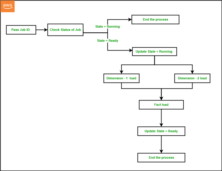
For example, a member of your data analytics team needs to trigger an AWS Step Functions workflow to reprocess a batch data job. Instead of granting the user direct access to the Step Functions workflow in the AWS Management Console or AWS CLI, you can provide access to invoke the workflow from within a designated Slack channel.
This blog covers how serverless architecture lets Slack users invoke AWS resources such as AWS Lambda functions and Step Functions via the Slack Desktop UI and Mobile UI using Slack apps. Serverless architecture is ideal for a Slack app because of its ability to scale. It can process thousands of concurrent requests for Slack users without the burden of managing operational overhead.
This example supports integration with other AWS resources via Step Functions. Visit the documentation for more information on integrations with other AWS resources.
This post explains the serverless example architecture, and walks through how to deploy the example in your AWS account. It demonstrates the example and discusses constraints discovered during development.
Overview
The code included in this post creates a Slack app built with a variety of AWS serverless services:
- Amazon API Gateway receives all incoming requests from Slack. Step Functions coordinates request activities such as user validation, configuration retrieval, request routing, and response formatting.
- A Lambda Function invokes Slack-specific authentication functionality and sends responses to the Slack UI.
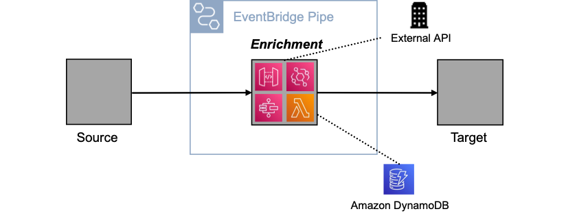
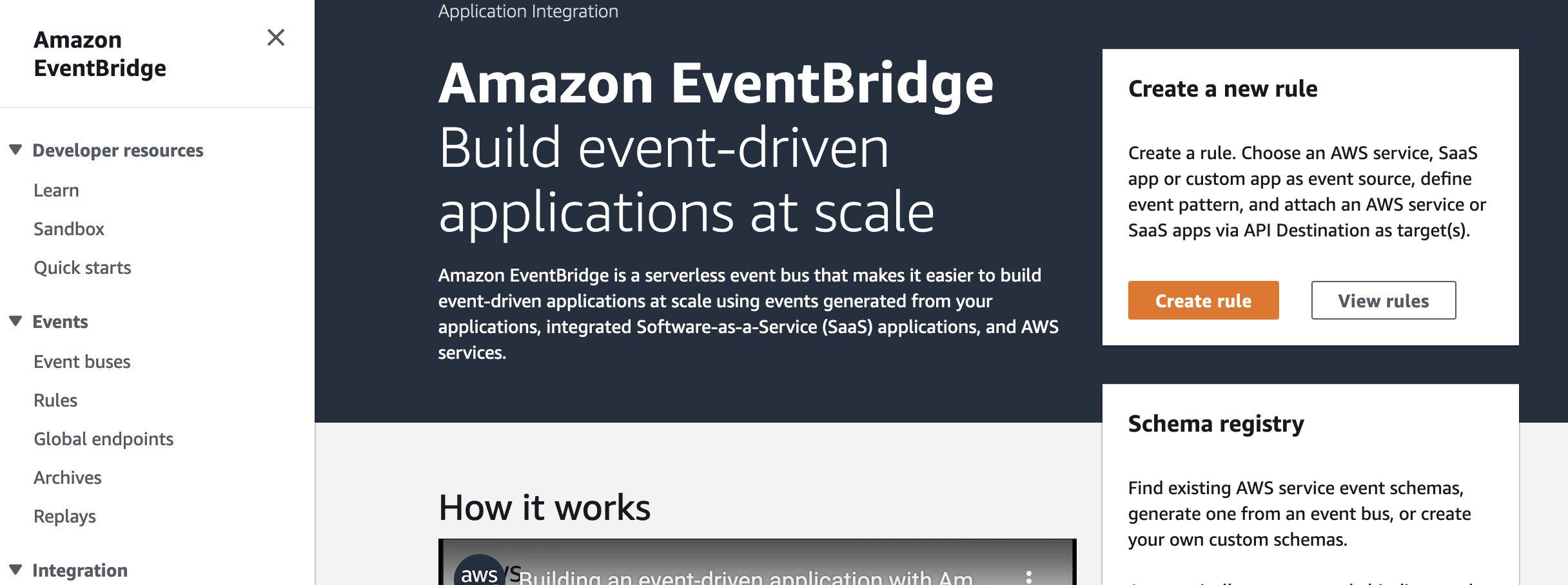
- Amazon EventBridge serves as a pub-sub integration between a request and the request processor.
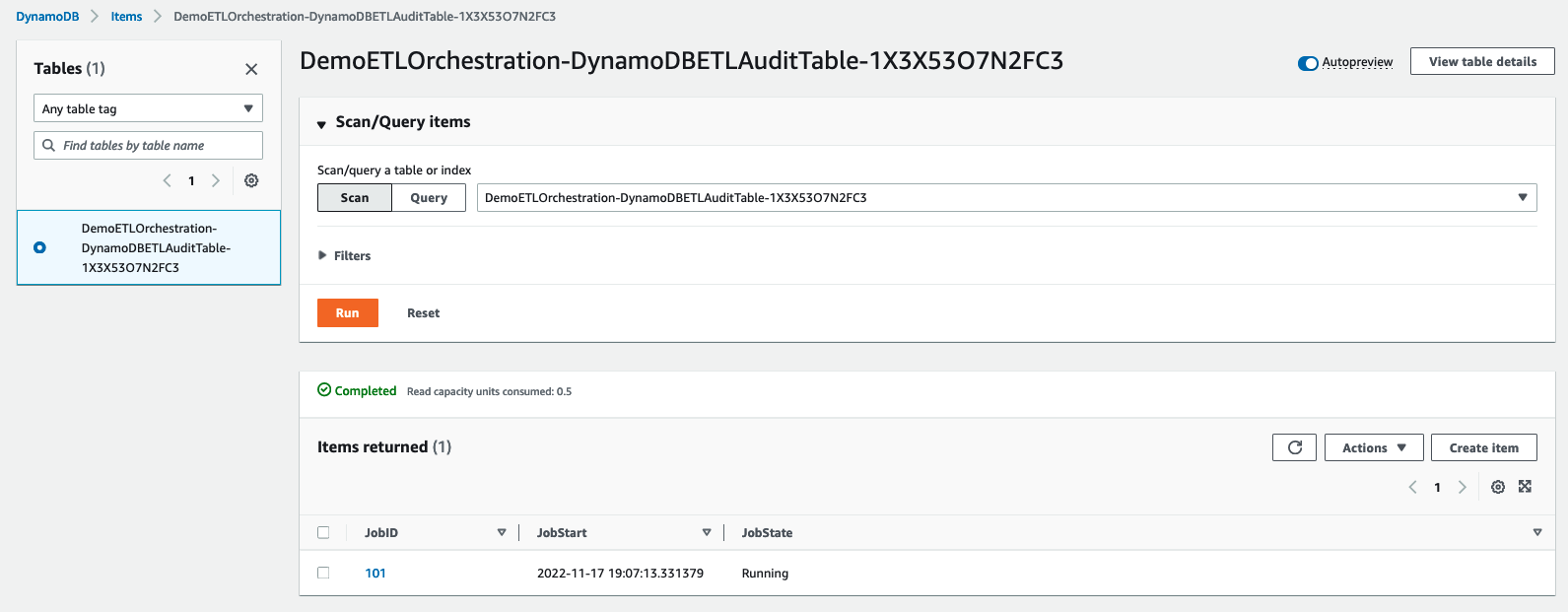
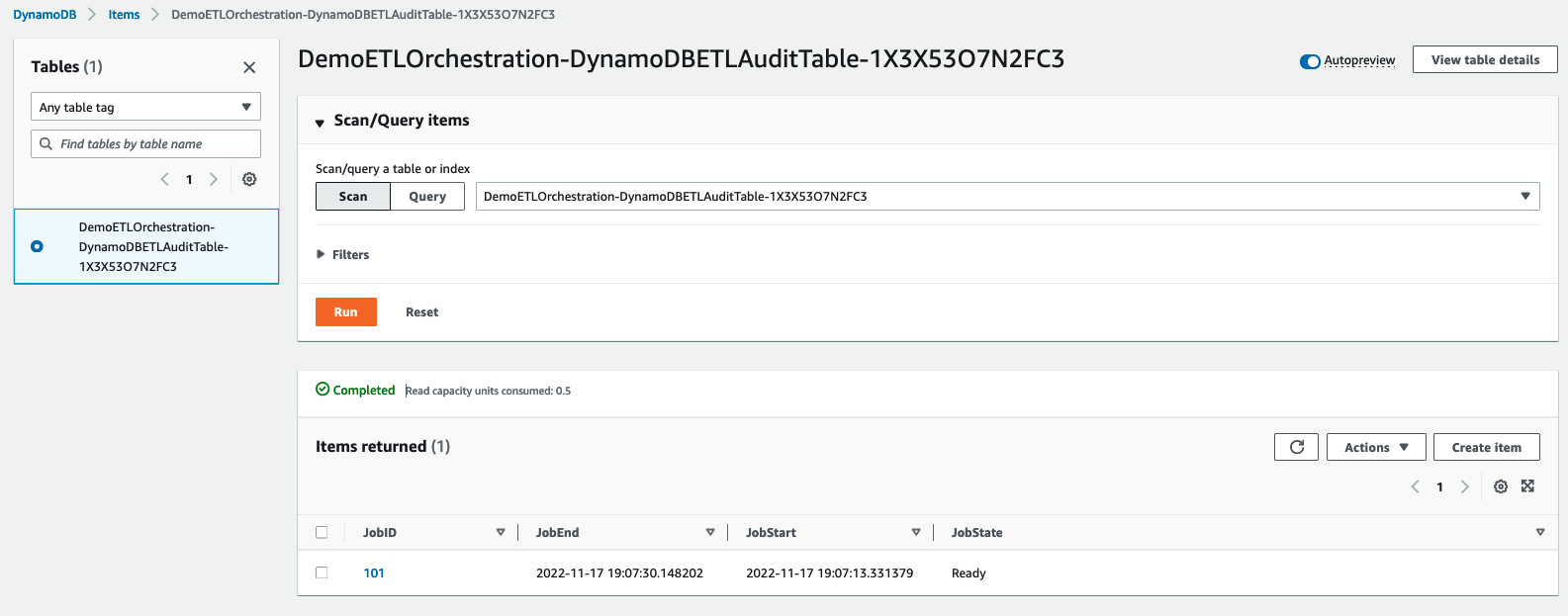
- Amazon DynamoDB stores permissions for each Slack user to ensure they only have access to resources you designate.
- AWS Systems Manager stores the specific Slack channel where you use the Slack app.
- AWS Secrets Manager stores the Slack app signing secret and bot token used for authentication.
AWS Cloud Development Kit (AWS CDK) deploys the AWS resources. This example can plug into any existing CI/CD platform of your choice.

Architectural overview
- The desktop or mobile Slack user starts requests by using /my-slack-bot slash command or by interacting with a Slack Block Kit UI element.
- API Gateway proxies the request and transforms the payload into a format that the request validator Step Functions workflow can accept.
- The request validator triggers the Slack authentication Lambda function to verify that the request originates from the configured Slack organization. This Lambda function uses the Slack Bolt library for TypeScript to perform request authentication and extract request details into a consistent payload. Also, Secrets Manager stores a signing secret, which the Slack Bolt API uses during authentication.
- The request validator queries the Authorized Users DynamoDB table with the username extracted from the request payload. If the user does not exist, the request ends with an unauthorized response.
- The request validator retrieves the permitted channel ID and compares it to the channel ID found in the request. If the two channel IDs do not match, the request ends with an unauthorized response.
- The request validator sends the request to the Command event bus in EventBridge.
- The Command event bus uses the request’s action property to route the request to a request processor Step Functions workflow.
- Each processor Step Functions workflow may build Slack Block Kit UI elements, send updates to existing UI elements, or invoke existing Lambda functions and Step Functions workflows.
- The Slack desktop or mobile application displays new UI elements or presents updates to an existing request as it is processed. Users may interact with new UI elements to further a request or start over with an additional request.
This application architecture scales for production loads, providing capacity for processing thousands of concurrent Slack users (through the Slack platform itself), bypassing the need for direct AWS Management Console access. This architecture provides for easier extensibility of the chat application to support new commands as consumer needs arise.
Finally, the application’s architecture and implementation follow the AWS Well-Architected guidance for Operational Excellence, Security, Reliability, and Performance Efficiency.
- CDK manages application infrastructure for the Operational Excellence Pillar.
- Secrets Manager and DynamoDB encrypt data at rest for the Security Pillar.
- This architecture scales horizontally with Lambda functions and Step Functions for the Reliability Pillar.
- Serverless architecture removes the need to maintain physical servers for the Performance Efficiency Pillar.
Step Functions is suited for this example because the service supports integrations with many other AWS services. Step Functions allows this example to orchestrate interactions with Lambda functions, DynamoDB tables, and EventBridge event busses with minimal code.
This example takes advantage of Step Functions Express Workflows to support the high-volume, event-driven actions generated by the Slack app. The result of using Express Workflows is a responsive, scalable request processor capable of handling tens of thousands requests per second. To learn more, review the differences between standard and Express Workflows.
The presented example uses AWS Secrets Manager for storing and retrieving application credentials securely. AWS Secrets Manager provides the following benefits:
- Central, secure storage of secrets via encryption-at-rest.
- Ease of access management through AWS Identity and Access Management (IAM) permissions policies.
- Out-of-the-box integration support with all AWS services comprising the architecture
In addition, this example uses the AWS Systems Manager Parameter Store service for persisting our application’s configuration data for the Slack Channel ID. Among the benefits offered by AWS System Manager, this example takes advantage of storing encrypted configuration data with versioning support.
This example features a variety of interactions for the Slack Mobile or Desktop application, including displaying a welcome screen, entering form information, and reporting process status. EventBridge enables this example to route requests from the Request Validator Step Function using the serverless Event Bus and decouple each action from one another. We configure Rules to associate an event to a request processor Step Function.
Walkthrough
As prerequisites, you need the following:
- AWS CDK version 2.19.0 or later.
- Node version 16+.
- Docker-cli.
- Git.
- A personal or company Slack account with permissions to create applications.
- The Slack Channel ID of a channel in your Workspace for integration with the Slack App.

Slack channel details
To get the Channel ID, open the context menu on the Slack channel and select View channel details. The modal displays your Channel ID at the bottom:

Slack bot channel details
To learn more, visit Slack’s Getting Started with Bolt for JavaScript page.
The README document for the GitHub Repository titled, Amazon Interactive Slack App Starter Kit, contains a comprehensive walkthrough, including detailed steps for:
- Slack API configuration
- Application deployment via AWS Cloud Development Kit (CDK)
- Required updates for AWS Systems Manager Parameters and secrets
Demoing the Slack app
- Start the Slack app by invoking the /my-slack-bot slash command.

Start sample Lambda invocation
- From the My Slack Bot action menu, choose Sample Lambda.

Choosing sample Lambda
Choosing sample Lambda
- Enter command input, choose Submit, then observe the response (this input value applies to the sample Lambda function).

Sample Lambda submit

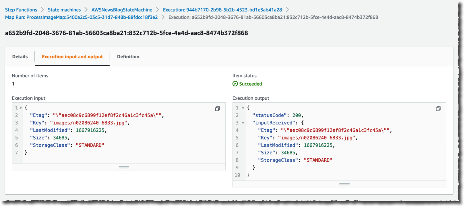
Sample Lambda results
- Start the Slack App by invoking the /my-slack-bot slash command, then select Sample State Machine:

Start sample state machine invocation

Select Sample State Machine
- Enter command input, choose Submit, then observe the response (this input value applies to the downstream state machine)

Sample state machine submit

Sample state machine results


Constraints in this example
Slack has constraints for sending and receiving requests, but API Gateway’s mapping templates provide mechanisms for integrating with a variety of request constraints.
Slack uses application/x-www-form-urlencoded to send requests to a custom URL. We designed a request template to format the input from Slack into a consistent format for the Request Validator Step Function. Headers such as X-Slack-Signature and X-Slack-Request-Timestamp needed to be passed along to ensure the request from Slack was authentic.
Here is the request mapping template needed for the integration:
{
  "stateMachineArn": "arn:aws:states:us-east-1:827819197510:stateMachine:RequestValidatorB6FDBF18-FACc7f2PzNAv",
  "input": "{\"body\": \"$input.path('$')\", \"headers\": {\"X-Slack-Signature\": \"$input.params().header.get('X-Slack-Signature')\", \"X-Slack-Request-Timestamp\": \"$input.params().header.get('X-Slack-Request-Timestamp')\", \"Content-Type\": \"application/x-www-form-urlencoded\"}}"
}
Slack sends the message payload in two different formats: URL-encoded and JSON. Fortunately, the Slack Bolt for JavaScript library can merge the two request formats into a single JSON payload and handle verification.
Slack requires a 204 status response along with an empty body to recognize that a request was successful. An integration response template overrides the Step Function response into a format that Slack accepts.
Here is the response mapping template needed for the integration:
#set($context.responseOverride.status = 204)
{}
Conclusion
In this blog post, you learned how you can let your organization’s Slack users with the ability to invoke your existing AWS resources with no AWS Management Console or AWS CLI access. This serverless example lets you build your own custom workflows to meet your organization’s needs.
To learn more about the concepts discussed in this blog, visit:
- AWS Lambda Node.js library
- Using TypeScript — Slack Bolt for JavaScript
- AWS Secrets Manager construct library
- Using AWS Step Functions with other services
For more serverless learning resources, visit Serverless Land.


 Debaprasun Chakraborty is an AWS Solutions Architect, specializing in the analytics domain. He has around 20 years of software development and architecture experience. He is passionate about helping customers in cloud adoption, migration and strategy.
 Suraj Subramani Vineet is a Senior Cloud Architect at Amazon Web Services (AWS) Professional Services in Sydney, Australia. He specializes in designing and building scalable and cost-effective data platforms and AI/ML solutions in the cloud. Outside of work, he enjoys playing soccer on weekends.


 Victor Gu is a Containers and Serverless Architect at AWS. He works with AWS customers to design microservices and cloud native solutions using Amazon EKS/ECS and AWS serverless services. His specialties are Kubernetes, Spark on Kubernetes, MLOps and DevOps.
 Michael Gasch is a Senior Product Manager for AWS EventBridge, driving innovations in event-driven architectures. Prior to AWS, Michael was a Staff Engineer at the VMware Office of the CTO, working on open-source projects, such as Kubernetes and Knative, and related distributed systems research.
 Peter Dalbhanjan is a Solutions Architect for AWS based in Herndon, VA. Peter has a keen interest in evangelizing AWS solutions and has written multiple blog posts that focus on simplifying complex use cases. At AWS, Peter helps with designing and architecting variety of customer workloads.


 Amazon EventBridge Scheduler | Schedule tasks over +200 targets!