Tag Archives: AWS Step Functions

The serverless attendee’s guide to AWS re:Invent 2023

Post Syndicated from Marcia Villalba original https://aws.amazon.com/blogs/compute/the-serverless-attendees-guide-to-aws-reinvent-2023/

AWS re:Invent 2023 is fast approaching, bringing together tens of thousands of Builders in Las Vegas in November. However, even if you can’t attend in person, you can catch up with sessions on-demand.

Breakout sessions are lecture-style 60-minute informative sessions presented by AWS experts, customers, or partners. These sessions cover beginner (100 level) topics to advanced and expert (300–400 level) topics. The sessions are recorded and uploaded a few days after to the AWS Events YouTube channel.

This post shares the “must watch” breakout sessions related to serverless architectures and services.

Sessions related to serverless architecture

SVS401

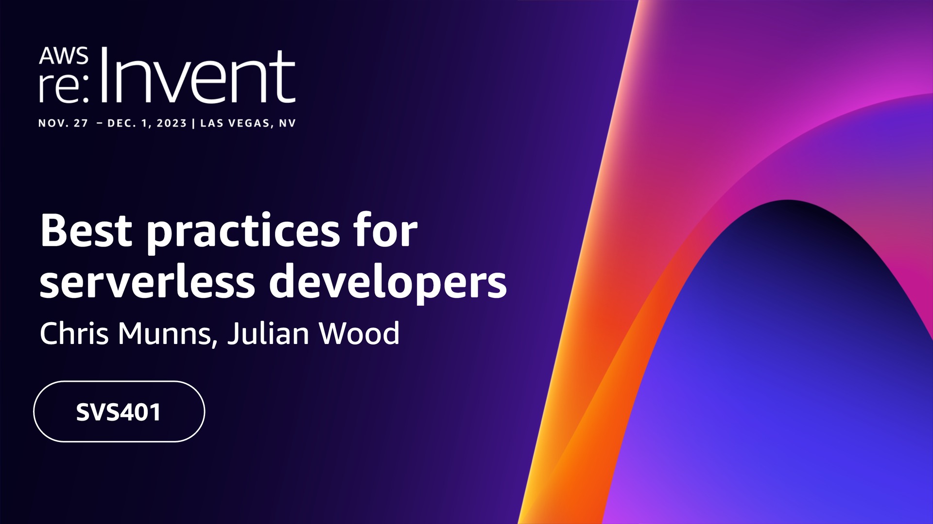
SVS401 | Best practices for serverless developers
Provides architectural best practices, optimizations, and useful shortcuts that experts use to build secure, high-scale, and high-performance serverless applications.

Chris Munns, Startup Tech Leader, AWS
Julian Wood, Principal Developer Advocate, AWS

SVS305 | Refactoring to serverless
Shows how you can refactor your application to serverless with real-life examples.

Gregor Hohpe, Senior Principal Evangelist, AWS
Sindhu Pillai, Senior Solutions Architect, AWS

SVS308 | Building low-latency, event-driven applications
Explores building serverless web applications for low-latency and event-driven support. Marvel Snap share how they achieve low-latency in their games using serverless technology.

Marcia Villalba, Principal Developer Advocate, AWS
Brenna Moore, Second Dinner

SVS309 | Improve productivity by shifting more responsibility to developers
Learn about approaches to accelerate serverless development with faster feedback cycles, exploring best practices and tools. Watch a live demo featuring an improved developer experience for building serverless applications while complying with enterprise governance requirements.

Heeki Park, Principal Solutions Architect, AWS
Sam Dengler, Capital One

GBL203-ES | Building serverless-first applications with MAPFRE
This session is delivered in Spanish. Learn what modern, serverless-first applications are and how to implement them with services such as AWS Lambda or AWS Fargate. Find out how MAPFRE have adopted and implemented a serverless strategy.

Jesus Bernal, Senior Solutions Architect, AWS
Iñigo Lacave, MAPFRE
Mat Jovanovic, MAPFRE

Sessions related to AWS Lambda

BOA311

BOA311 | Unlocking serverless web applications with AWS Lambda Web Adapter
Learn about the AWS Lambda Web Adapter and how it integrates with familiar frameworks and tools. Find out how to migrate existing web applications to serverless or create new applications using AWS Lambda.

Betty Zheng, Senior Developer Advocate, AWS
Harold Sun, Senior Solutions Architect, AWS

OPN305 | The pragmatic serverless Python developer
Covers an opinionated approach to setting up a serverless Python project, including testing, profiling, deployments, and operations. Learn about many open source tools, including Powertools for AWS Lambda—a toolkit that can help you implement serverless best practices and increase developer velocity.

Heitor Lessa, Principal Solutions Architect, AWS
Ran Isenberg, CyberArk

XNT301 | Build production-ready serverless .NET apps with AWS Lambda
Explores development and architectural best practices when building serverless applications with .NET and AWS Lambda, including when to run ASP.NET on Lambda, code structure, and using native AOT to massively increase performance.

James Eastham, Senior Cloud Architect, AWS
Craig Bossie, Solutions Architect, AWS

COM306 | “Rustifying” serverless: Boost AWS Lambda performance with Rust
Discover how to deploy Rust functions using AWS SAM and cargo-lambda, facilitating a smooth development process from your local machine. Explore how to integrate Rust into Python Lambda functions effortlessly using tools like PyO3 and maturin, along with the AWS SDK for Rust. Uncover how Rust can optimize Lambda functions, including the development of Lambda extensions, all without requiring a complete rewrite of your existing code base.

Efi Merdler-Kravitz, Cloudex

COM305 | Demystifying and mitigating AWS Lambda cold starts
Examines the Lambda initialization process at a low level, using benchmarks comparing common architectural patterns, and then benchmarking various RAM configurations and payload sizes. Next, measure and discuss common mistakes that can increase initialization latency, explore and understand proactive initialization, and learn several strategies you can use to thaw your AWS Lambda cold starts.

AJ Stuyvenberg, Datadog

Sessions related to event-driven architecture

API302

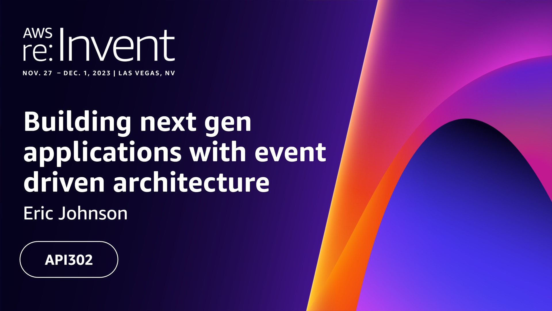
API302 | Building next gen applications with event driven architecture
Learn about common integration patterns and discover how you can use AWS messaging services to connect microservices and coordinate data flow using minimal custom code. Learn and plan for idempotency, handling duplicating events and building resiliency into your architectures.

Eric Johnson, Principal Developer Advocate, AWS

API303 | Navigating the journey of serverless event-driven architecture
Learn about the journey businesses undertake when adopting EDAs, from initial design and implementation to ongoing operation and maintenance. The session highlights the many benefits EDAs can offer organizations and focuses on areas of EDA that are challenging and often overlooked. Through a combination of patterns, best practices, and practical tips, this session provides a comprehensive overview of the opportunities and challenges of implementing EDAs and helps you understand how you can use them to drive business success.

David Boyne, Senior Developer Advocate, AWS

API309 | Advanced integration patterns and trade-offs for loosely coupled apps
In this session, learn about common design trade-offs for distributed systems, how to navigate them with design patterns, and how to embed those patterns in your cloud automation.

Dirk Fröhner, Principal Solutions Architect, AWS
Gregor Hohpe, Senior Principal Evangelist, AWS

SVS205 | Getting started building serverless event-driven applications
Learn about the process of prototyping a solution from concept to a fully featured application that uses Amazon API Gateway, AWS Lambda, Amazon EventBridge, AWS Step Functions, Amazon DynamoDB, AWS Application Composer, and more. Learn why serverless is a great tool set for experimenting with new ideas and how the extensibility and modularity of serverless applications allow you to start small and quickly make your idea a reality.

Emily Shea, Head of Application Integration Go-to-Market, AWS
Naren Gakka, Solutions Architect, AWS

API206 | Bringing workloads together with event-driven architecture
Attend this session to learn the steps to bring your existing container workloads closer together using event-driven architecture with minimal code changes and a high degree of reusability. Using a real-life business example, this session walks through a demo to highlight the power of this approach.

Dhiraj Mahapatro, Principal Solutions Architect, AWS
Nicholas Stumpos, JPMorgan Chase & Co

COM301 | Advanced event-driven patterns with Amazon EventBridge
Gain an understanding of the characteristics of EventBridge and how it plays a pivotal role in serverless architectures. Learn the primary elements of event-driven architecture and some of the best practices. With real-world use cases, explore how the features of EventBridge support implementing advanced architectural patterns in serverless.

Sheen Brisals, The LEGO Group

Sessions related to serverless APIs

SVS301

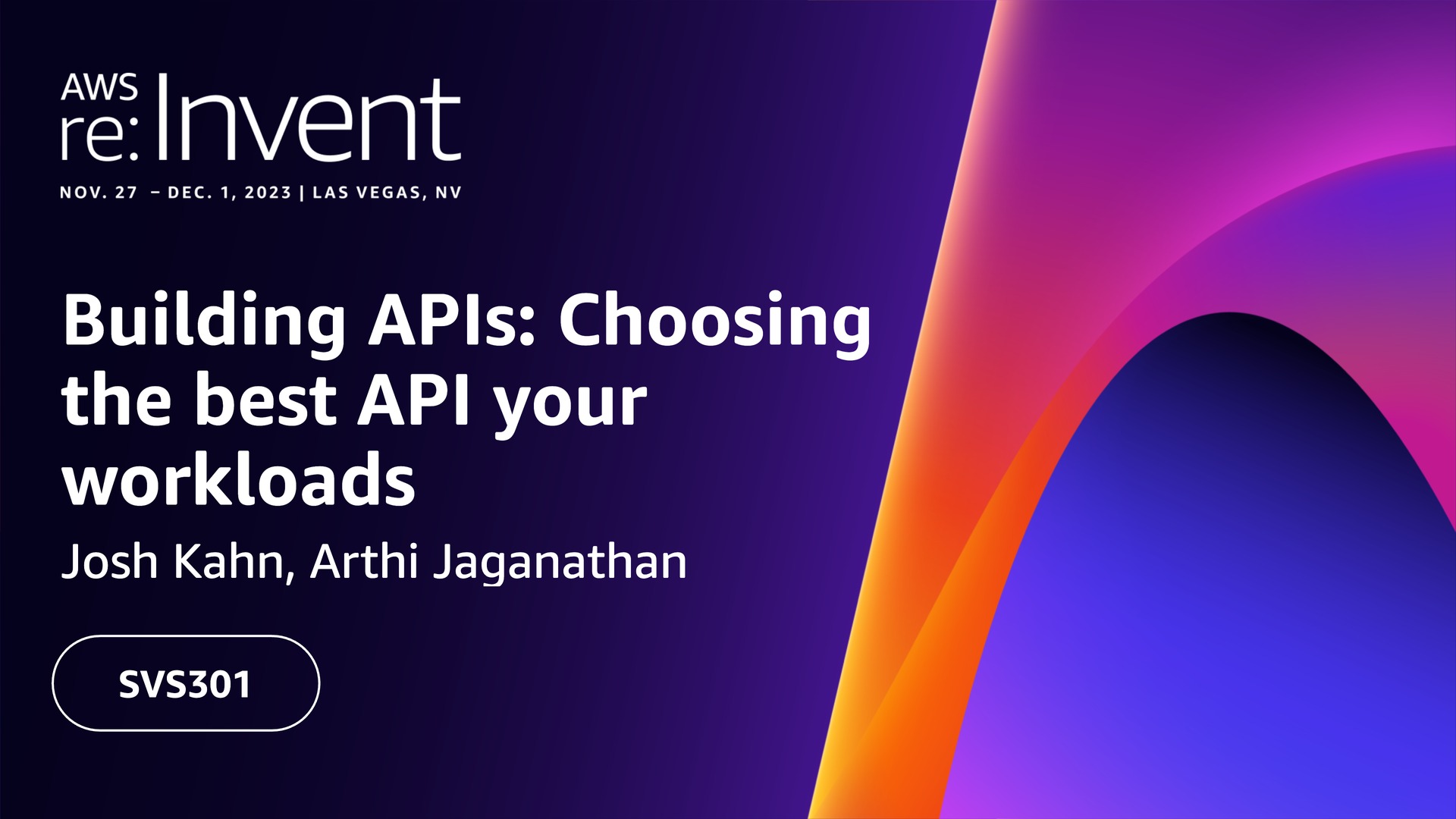
SVS301 | Building APIs: Choosing the best API solution and strategy for your workloads
Learn about access patterns and how to evaluate the best API technology for your applications. The session considers the features and benefits of Amazon API Gateway, AWS AppSync, Amazon VPC Lattice, and other options.

Josh Kahn, Tech Leader Serverless, AWS
Arthi Jaganathan, Principal Solutions Architect, AWS

SVS323 | I didn’t know Amazon API Gateway did that
This session provides an introduction to Amazon API Gateway and the problems it solves. Learn about the moving parts of API Gateway and how it works, including common and not-so-common use cases. Discover why you should use API Gateway and what it can do.

Eric Johnson, Principal Developer Advocate, AWS

FWM201 | What’s new with AWS AppSync for enterprise API developers
Join this session to learn about all the exciting new AWS AppSync features released this year that make it even more seamless for API developers to realize the benefits of GraphQL for application development.

Michael Liendo, Senior Developer Advocate, AWS
Brice Pellé, Principal Product Manager, AWS

FWM204 | Implement real-time event patterns with WebSockets and AWS AppSync
Learn how the PGA Tour uses AWS AppSync to deliver real-time event updates to their app users; review new features, like enhanced filtering options and native integration with Amazon EventBridge; and provide a sneak peek at what’s coming next.

Ryan Yanchuleff, Senior Solutions Architect, AWS
Bill Fine, Senior Product Manager, AWS
David Provan, PGA Tour

Sessions related to AWS Step Functions

API401

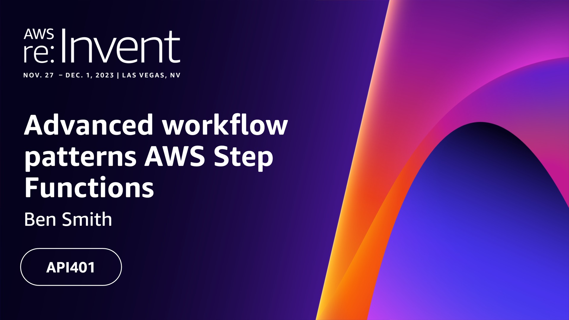
API401 | Advanced workflow patterns and business processes with AWS Step Functions
Learn about architectural best practices and repeatable patterns for building workflows and cost optimizations, and discover handy cheat codes that you can use to build secure, high-scale, high-performance serverless applications

Ben Smith, Principal Developer Advocate, AWS

BOA304 | Using AI and serverless to automate video production
Learn how to use Step Functions to build workflows using AI services and how to use Amazon EventBridge real-time events.

Marcia Villalba, Principal Developer Advocate, AWS

SVS204 | Building Serverlesspresso: Creating event-driven architectures
This session explores the design decisions that were made when building Serverlesspresso, how new features influenced the development process, and lessons learned when creating a production-ready application using this approach. Explore useful patterns and options for extensibility that helped in the design of a robust, scalable solution that costs about one dollar per day to operate. This session includes examples you can apply to your serverless applications and complex architectural challenges for larger applications.

James Beswick, Senior Manager Developer Advocacy, AWS

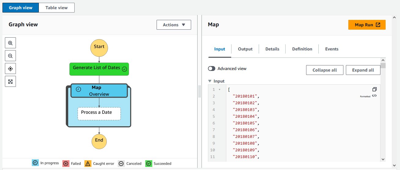
API310 | Scale interactive data analysis with Step Functions Distributed Map
Learn how to build a data processing or other automation once and readily scale it to thousands of parallel processes with serverless technologies. Explore how this approach simplifies development and error handling while improving speed and lowering cost. Hear from an AWS customer that refactored an existing machine learning application to use Distributed Map and the lessons they learned along the way.

Adam Wagner, Principal Solutions Architect, AWS
Roberto Iturralde, Vertex Pharmaceuticals

Sessions related to handling data using serverless services and serverless databases

SVS307

SVS307 | Scaling your serverless data processing with Amazon Kinesis and Kafka
Explore how to build scalable data processing applications using AWS Lambda. Learn practical insights into integrating Lambda with Amazon Kinesis and Apache Kafka using their event-driven models for real-time data streaming and processing.

Julian Wood, Principal Developer Advocate, AWS

DAT410 | Advanced data modeling with Amazon DynamoDB
This session shows you advanced techniques to get the most out of DynamoDB. Learn how to “think in DynamoDB” by learning the DynamoDB foundations and principles for data modeling. Learn practical strategies and DynamoDB features to handle difficult use cases in your application.

Alex De Brie – Independent consultant

COM308 | Serverless data streaming: Amazon Kinesis Data Streams and AWS Lambda
Explore the intricacies of creating scalable, production-ready data streaming architectures using Kinesis Data Streams and Lambda. Delve into tips and best practices essential to navigating the challenges and pitfalls inherent to distributed systems that arise along the way, and observe how AWS services work and interact.

Anahit Pogosova, Solita

Additional resources

If you are attending the event, there are many chalk talks, workshops, and other sessions to visit. See ServerlessLand for a full list of all the serverless sessions and also the Serverless Hero, Danielle Heberling’s Serverless re:Invent attendee guide for her top picks.

Visit us in the AWS Village in the Expo Hall where you can find the Serverless and Containers booth and enjoy a free cup of coffee at Serverlesspresso.

For more serverless learning resources, visit Serverless Land.

Orchestrating dependent file uploads with AWS Step Functions

Post Syndicated from Benjamin Smith original https://aws.amazon.com/blogs/compute/orchestrating-dependent-file-uploads-with-aws-step-functions/

This post is written by Nelson Assis, Enterprise Support Lead, Serverless and Jevon Liburd, Technical Account Manager, Serverless

Amazon S3 is an object storage service that many customers use for file storage. With the use of Amazon S3 Event Notifications or Amazon EventBridge customers can create workloads with event-driven architecture (EDA). This architecture responds to events produced when changes occur to objects in S3 buckets.

EDA involves asynchronous communication between system components. This serves to decouple the components allowing each component to be autonomous.

Some scenarios may introduce coupling in the architecture due to dependency between events. This blog post presents a common example of this coupling and how it can be handled using AWS Step Functions.

Overview

In this example, an organization has two distributed autonomous teams, the Sales team and the Warehouse team. Each team is responsible for uploading a monthly data file to an S3 bucket so it can be processed.

The files generate events when they are uploaded, initiating downstream processes. The processing of the Warehouse file cleans the data and joins it with data from the Shipping team. The processing of the Sales file correlates the data with the combined Warehouse and Shipping data. This enables analysts to perform forecasting and gain other insights.

For this correlation to happen, the Warehouse file must be processed before the Sales file. As the two teams are autonomous, there is no coordination among the teams. This means that the files can be uploaded at any time with no assurance that the Warehouse file is processed before the Sales file.

For scenarios like these, the Aggregator pattern can be used. The pattern collects and stores the events, and triggers a new event based on the combined events. In the described scenario, the combined events are the processed Warehouse file and the uploaded Sales file.

The requirements of the aggregator pattern are:

  1. Correlation – A way to group the related events. This is fulfilled by a unique identifier in the file name.
  2. Event aggregator – A stateful store for the events.
  3. Completion check and trigger – A condition when the combined events have been received and a way to publish the resulting event.

Architecture overview

The architecture uses the following AWS services:

  1. File upload: The Sales and Warehouse teams upload their respective files to S3.
  2. EventBridge: The ObjectCreated event is sent to EventBridge where there is a rule with a target of the main workflow.
  3. Main state machine: This state machine orchestrates the aggregator operations and the processing of the files. It encapsulates the workflows for each file to separate the aggregator logic from the files’ workflow logic.
  4. File parser and correlation: The business logic to identify the file and its type is run in this Lambda function.
  5. Stateful store: A DynamoDB table stores information about the file such as the name, type, and processing status. The state machine reads from and writes to the DynamoDB table. Task tokens are also stored in this table.
  6. File processing: Depending on the file type and any pre-conditions, state machines corresponding to the file type are run. These state machines contain the logic to process the specific file.
  7. Task Token & Callback: The task token is generated when the dependent file tries to be processed before the independent file. The Step Functions “Wait for a Callback” pattern continues the execution of the dependent file after the independent file is processed.

Walkthrough

You need the following prerequisites:

  • AWS CLI and AWS SAM CLI installed.
  • An AWS account.
  • Sufficient permissions to manage the AWS resources.
  • Git installed.

To deploy the example, follow the instructions in the GitHub repo.

This walkthrough shows what happens if the dependent file (Sales file) is uploaded before the independent one (Warehouse file).

  1. The workflow starts with the uploading of the Sales file to the dedicated Sales S3 bucket. The example uses separate S3 buckets for the two files as it assumes that the Sales and Warehouse teams are distributed and autonomous. You can find sample files in the code repository.
  2. Uploading the file to S3 sends an event to EventBridge, which the aggregator state machine acts on. The event pattern used in the EventBridge rule is:
    {
      "detail-type": ["Object Created"],
      "source": ["aws.s3"],
      "detail": {
        "bucket": {
          "name": ["sales-mfu-eda-09092023", "warehouse-mfu-eda-09092023"]
        },
        "reason": ["PutObject"]
      }
    }
  3. The aggregator state machine starts by invoking the file parser Lambda function. This function parses the file type and uses the identifier to correlate the files. In this example, the name of the file contains the file type and the correlation identifier (the year_month). To use other ways of representing the file type and correlation identifier, you can modify this function to parse that information.
  4. The next step in the state machine inserts a record for the event in the event aggregator DynamoDB table. The table has a composite primary key with the correlation identifier as the partition key and the file type as the sort key. The processing status of the file is tracked to give feedback on the state of the workflow.
  5. Based on the file type, the state machine determines which branch to follow. In the example, the Sales branch is run. The state machine tries to get the status of the (dependent) Warehouse file from DynamoDB using the correlation identifier. Using the result of this query, the state machine determines if the corresponding Warehouse file has already been processed.
  6. Since the Warehouse file is not processed yet, the waitForTaskToken integration pattern is used. The state machine waits at this step and creates a task token, which the external services use to trigger the state machine to continue its execution. The Sales record in the DynamoDB table is updated with the Task Token.
  7. Navigate to the S3 console and upload the sample Warehouse file to the Warehouse S3 bucket. This invokes a new instance of the Step Functions workflow, which flows through the other branch after the file type choice step. In this branch, the Warehouse state machine is run and the processing status of the file is updated in DynamoDB.

When the status of the Warehouse file is changed to “Completed”, the Warehouse state machine checks DynamoDB for a pending Sales file. If there is one, it retrieves the task token and calls the SendTaskSuccess method. This triggers the Sales state machine, which is in a waiting state to continue. The Sales state machine is started and the processing status is updated.

Conclusion

This blog post shows how to handle file dependencies in event driven architectures. You can customize the sample provided in the code repository for your own use case.

This solution is specific to file dependencies in event driven architectures. For more information on solving event dependencies and aggregators read the blog post: Moving to event-driven architectures with serverless event aggregators.

To learn more about event driven architectures, visit the event driven architecture section on Serverless Land.

Sending and receiving webhooks on AWS: Innovate with event notifications

Post Syndicated from James Beswick original https://aws.amazon.com/blogs/compute/sending-and-receiving-webhooks-on-aws-innovate-with-event-notifications/

This post is written by Daniel Wirjo, Solutions Architect, and Justin Plock, Principal Solutions Architect.

Commonly known as reverse APIs or push APIs, webhooks provide a way for applications to integrate to each other and communicate in near real-time. It enables integration for business and system events.

Whether you’re building a software as a service (SaaS) application integrating with your customer workflows, or transaction notifications from a vendor, webhooks play a critical role in unlocking innovation, enhancing user experience, and streamlining operations.

This post explains how to build with webhooks on AWS and covers two scenarios:

  • Webhooks Provider: A SaaS application that sends webhooks to an external API.
  • Webhooks Consumer: An API that receives webhooks with capacity to handle large payloads.

It includes high-level reference architectures with considerations, best practices and code sample to guide your implementation.

Sending webhooks

To send webhooks, you generate events, and deliver them to third-party APIs. These events facilitate updates, workflows, and actions in the third-party system. For example, a payments platform (provider) can send notifications for payment statuses, allowing ecommerce stores (consumers) to ship goods upon confirmation.

AWS reference architecture for a webhook provider

The architecture consists of two services:

  • Webhook delivery: An application that delivers webhooks to an external endpoint specified by the consumer.
  • Subscription management: A management API enabling the consumer to manage their configuration, including specifying endpoints for delivery, and which events for subscription.

AWS reference architecture for a webhook provider

Considerations and best practices for sending webhooks

When building an application to send webhooks, consider the following factors:

Event generation: Consider how you generate events. This example uses Amazon DynamoDB as the data source. Events are generated by change data capture for DynamoDB Streams and sent to Amazon EventBridge Pipes. You then simplify the DynamoDB response format by using an input transformer.

With EventBridge, you send events in near real time. If events are not time-sensitive, you can send multiple events in a batch. This can be done by polling for new events at a specified frequency using EventBridge Scheduler. To generate events from other data sources, consider similar approaches with Amazon Simple Storage Service (S3) Event Notifications or Amazon Kinesis.

Filtering: EventBridge Pipes support filtering by matching event patterns, before the event is routed to the target destination. For example, you can filter for events in relation to status update operations in the payments DynamoDB table to the relevant subscriber API endpoint.

Delivery: EventBridge API Destinations deliver events outside of AWS using REST API calls. To protect the external endpoint from surges in traffic, you set an invocation rate limit. In addition, retries with exponential backoff are handled automatically depending on the error. An Amazon Simple Queue Service (SQS) dead-letter queue retains messages that cannot be delivered. These can provide scalable and resilient delivery.

Payload Structure: Consider how consumers process event payloads. This example uses an input transformer to create a structured payload, aligned to the CloudEvents specification. CloudEvents provides an industry standard format and common payload structure, with developer tools and SDKs for consumers.

Payload Size: For fast and reliable delivery, keep payload size to a minimum. Consider delivering only necessary details, such as identifiers and status. For additional information, you can provide consumers with a separate API. Consumers can then separately call this API to retrieve the additional information.

Security and Authorization: To deliver events securely, you establish a connection using an authorization method such as OAuth. Under the hood, the connection stores the credentials in AWS Secrets Manager, which securely encrypts the credentials.

Subscription Management: Consider how consumers can manage their subscription, such as specifying HTTPS endpoints and event types to subscribe. DynamoDB stores this configuration. Amazon API Gateway, Amazon Cognito, and AWS Lambda provide a management API for operations.

Costs: In practice, sending webhooks incurs cost, which may become significant as you grow and generate more events. Consider implementing usage policies, quotas, and allowing consumers to subscribe only to the event types that they need.

Monetization: Consider billing consumers based on their usage volume or tier. For example, you can offer a free tier to provide a low-friction access to webhooks, but only up to a certain volume. For additional volume, you charge a usage fee that is aligned to the business value that your webhooks provide. At high volumes, you offer a premium tier where you provide dedicated infrastructure for certain consumers.

Monitoring and troubleshooting: Beyond the architecture, consider processes for day-to-day operations. As endpoints are managed by external parties, consider enabling self-service. For example, allow consumers to view statuses, replay events, and search for past webhook logs to diagnose issues.

Advanced Scenarios: This example is designed for popular use cases. For advanced scenarios, consider alternative application integration services noting their Service Quotas. For example, Amazon Simple Notification Service (SNS) for fan-out to a larger number of consumers, Lambda for flexibility to customize payloads and authentication, and AWS Step Functions for orchestrating a circuit breaker pattern to deactivate unreliable subscribers.

Receiving webhooks

To receive webhooks, you require an API to provide to the webhook provider. For example, an ecommerce store (consumer) may rely on notifications provided by their payment platform (provider) to ensure that goods are shipped in a timely manner. Webhooks present a unique scenario as the consumer must be scalable, resilient, and ensure that all requests are received.

AWS reference architecture for a webhook consumer

In this scenario, consider an advanced use case that can handle large payloads by using the claim-check pattern.

AWS reference architecture for a webhook consumer

At a high-level, the architecture consists of:

  • API: An API endpoint to receive webhooks. An event-driven system then authorizes and processes the received webhooks.
  • Payload Store: S3 provides scalable storage for large payloads.
  • Webhook Processing: EventBridge Pipes provide an extensible architecture for processing. It can batch, filter, enrich, and send events to a range of processing services as targets.

Considerations and best practices for receiving webhooks

When building an application to receive webhooks, consider the following factors:

Scalability: Providers typically send events as they occur. API Gateway provides a scalable managed endpoint to receive events. If unavailable or throttled, providers may retry the request, however, this is not guaranteed. Therefore, it is important to configure appropriate rate and burst limits. Throttling requests at the entry point mitigates impact on downstream services, where each service has its own quotas and limits. In many cases, providers are also aware of impact on downstream systems. As such, they send events at a threshold rate limit, typically up to 500 transactions per second (TPS).

Considerations and best practices for receiving webhooks

In addition, API Gateway allows you to validate requests, monitor for any errors, and protect against distributed denial of service (DDoS). This includes Layer 7 and Layer 3 attacks, which are common threats to webhook consumers given public exposure.

Authorization and Verification: Providers can support different authorization methods. Consider a common scenario with Hash-based Message Authentication Code (HMAC), where a shared secret is established and stored in Secrets Manager. A Lambda function then verifies integrity of the message, processing a signature in the request header. Typically, the signature contains a timestamped nonce with an expiry to mitigate replay attacks, where events are sent multiple times by an attacker. Alternatively, if the provider supports OAuth, consider securing the API with Amazon Cognito.

Payload Size: Providers may send a variety of payload sizes. Events can be batched to a single larger request, or they may contain significant information. Consider payload size limits in your event-driven system. API Gateway and Lambda have limits of 10 Mb and 6 Mb. However, DynamoDB and SQS are limited to 400kb and 256kb (with extension for large messages) which can represent a bottleneck.

Instead of processing the entire payload, S3 stores the payload. It is then referenced in DynamoDB, via its bucket name and object key. This is known as the claim-check pattern. With this approach, the architecture supports payloads of up to 6mb, as per the Lambda invocation payload quota.

Considerations and best practices for receiving webhooks

Idempotency: For reliability, many providers prioritize delivering at-least-once, even if it means not guaranteeing exactly once delivery. They can transmit the same request multiple times, resulting in duplicates. To handle this, a Lambda function checks against the event’s unique identifier against previous records in DynamoDB. If not already processed, you create a DynamoDB item.

Ordering: Consider processing requests in its intended order. As most providers prioritize at-least-once delivery, events can be out of order. To indicate order, events may include a timestamp or a sequence identifier in the payload. If not, ordering may be on a best-efforts basis based on when the webhook is received. To handle ordering reliably, select event-driven services that ensure ordering. This example uses DynamoDB Streams and EventBridge Pipes.

Flexible Processing: EventBridge Pipes provide integrations to a range of event-driven services as targets. You can route events to different targets based on filters. Different event types may require different processors. For example, you can use Step Functions for orchestrating complex workflows, Lambda for compute operations with less than 15-minute execution time, SQS to buffer requests, and Amazon Elastic Container Service (ECS) for long-running compute jobs. EventBridge Pipes provide transformation to ensure only necessary payloads are sent, and enrichment if additional information is required.

Costs: This example considers a use case that can handle large payloads. However, if you can ensure that providers send minimal payloads, consider a simpler architecture without the claim-check pattern to minimize cost.

Conclusion

Webhooks are a popular method for applications to communicate, and for businesses to collaborate and integrate with customers and partners.

This post shows how you can build applications to send and receive webhooks on AWS. It uses serverless services such as EventBridge and Lambda, which are well-suited for event-driven use cases. It covers high-level reference architectures, considerations, best practices and code sample to assist in building your solution.

For standards and best practices on webhooks, visit the open-source community resources Webhooks.fyi and CloudEvents.io.

For more serverless learning resources, visit Serverless Land.

Unstructured data management and governance using AWS AI/ML and analytics services

Post Syndicated from Sakti Mishra original https://aws.amazon.com/blogs/big-data/unstructured-data-management-and-governance-using-aws-ai-ml-and-analytics-services/

Unstructured data is information that doesn’t conform to a predefined schema or isn’t organized according to a preset data model. Unstructured information may have a little or a lot of structure but in ways that are unexpected or inconsistent. Text, images, audio, and videos are common examples of unstructured data. Most companies produce and consume unstructured data such as documents, emails, web pages, engagement center phone calls, and social media. By some estimates, unstructured data can make up to 80–90% of all new enterprise data and is growing many times faster than structured data. After decades of digitizing everything in your enterprise, you may have an enormous amount of data, but with dormant value. However, with the help of AI and machine learning (ML), new software tools are now available to unearth the value of unstructured data.

In this post, we discuss how AWS can help you successfully address the challenges of extracting insights from unstructured data. We discuss various design patterns and architectures for extracting and cataloging valuable insights from unstructured data using AWS. Additionally, we show how to use AWS AI/ML services for analyzing unstructured data.

Why it’s challenging to process and manage unstructured data

Unstructured data makes up a large proportion of the data in the enterprise that can’t be stored in a traditional relational database management systems (RDBMS). Understanding the data, categorizing it, storing it, and extracting insights from it can be challenging. In addition, identifying incremental changes requires specialized patterns and detecting sensitive data and meeting compliance requirements calls for sophisticated functions. It can be difficult to integrate unstructured data with structured data from existing information systems. Some view structured and unstructured data as apples and oranges, instead of being complementary. But most important of all, the assumed dormant value in the unstructured data is a question mark, which can only be answered after these sophisticated techniques have been applied. Therefore, there is a need to being able to analyze and extract value from the data economically and flexibly.

Solution overview

Data and metadata discovery is one of the primary requirements in data analytics, where data consumers explore what data is available and in what format, and then consume or query it for analysis. If you can apply a schema on top of the dataset, then it’s straightforward to query because you can load the data into a database or impose a virtual table schema for querying. But in the case of unstructured data, metadata discovery is challenging because the raw data isn’t easily readable.

You can integrate different technologies or tools to build a solution. In this post, we explain how to integrate different AWS services to provide an end-to-end solution that includes data extraction, management, and governance.

The solution integrates data in three tiers. The first is the raw input data that gets ingested by source systems, the second is the output data that gets extracted from input data using AI, and the third is the metadata layer that maintains a relationship between them for data discovery.

The following is a high-level architecture of the solution we can build to process the unstructured data, assuming the input data is being ingested to the raw input object store.

Unstructured Data Management - Block Level Architecture Diagram

The steps of the workflow are as follows:

  1. Integrated AI services extract data from the unstructured data.
  2. These services write the output to a data lake.
  3. A metadata layer helps build the relationship between the raw data and AI extracted output. When the data and metadata are available for end-users, we can break the user access pattern into additional steps.
  4. In the metadata catalog discovery step, we can use query engines to access the metadata for discovery and apply filters as per our analytics needs. Then we move to the next stage of accessing the actual data extracted from the raw unstructured data.
  5. The end-user accesses the output of the AI services and uses the query engines to query the structured data available in the data lake. We can optionally integrate additional tools that help control access and provide governance.
  6. There might be scenarios where, after accessing the AI extracted output, the end-user wants to access the original raw object (such as media files) for further analysis. Additionally, we need to make sure we have access control policies so the end-user has access only to the respective raw data they want to access.

Now that we understand the high-level architecture, let’s discuss what AWS services we can integrate in each step of the architecture to provide an end-to-end solution.

The following diagram is the enhanced version of our solution architecture, where we have integrated AWS services.

Unstructured Data Management - AWS Native Architecture

Let’s understand how these AWS services are integrated in detail. We have divided the steps into two broad user flows: data processing and metadata enrichment (Steps 1–3) and end-users accessing the data and metadata with fine-grained access control (Steps 4–6).

  1. Various AI services (which we discuss in the next section) extract data from the unstructured datasets.
  2. The output is written to an Amazon Simple Storage Service (Amazon S3) bucket (labeled Extracted JSON in the preceding diagram). Optionally, we can restructure the input raw objects for better partitioning, which can help while implementing fine-grained access control on the raw input data (labeled as the Partitioned bucket in the diagram).
  3. After the initial data extraction phase, we can apply additional transformations to enrich the datasets using AWS Glue. We also build an additional metadata layer, which maintains a relationship between the raw S3 object path, the AI extracted output path, the optional enriched version S3 path, and any other metadata that will help the end-user discover the data.
  4. In the metadata catalog discovery step, we use the AWS Glue Data Catalog as the technical catalog, Amazon Athena and Amazon Redshift Spectrum as query engines, AWS Lake Formation for fine-grained access control, and Amazon DataZone for additional governance.
  5. The AI extracted output is expected to be available as a delimited file or in JSON format. We can create an AWS Glue Data Catalog table for querying using Athena or Redshift Spectrum. Like the previous step, we can use Lake Formation policies for fine-grained access control.
  6. Lastly, the end-user accesses the raw unstructured data available in Amazon S3 for further analysis. We have proposed integrating Amazon S3 Access Points for access control at this layer. We explain this in detail later in this post.

Now let’s expand the following parts of the architecture to understand the implementation better:

  • Using AWS AI services to process unstructured data
  • Using S3 Access Points to integrate access control on raw S3 unstructured data

Process unstructured data with AWS AI services

As we discussed earlier, unstructured data can come in a variety of formats, such as text, audio, video, and images, and each type of data requires a different approach for extracting metadata. AWS AI services are designed to extract metadata from different types of unstructured data. The following are the most commonly used services for unstructured data processing:

  • Amazon Comprehend – This natural language processing (NLP) service uses ML to extract metadata from text data. It can analyze text in multiple languages, detect entities, extract key phrases, determine sentiment, and more. With Amazon Comprehend, you can easily gain insights from large volumes of text data such as extracting product entity, customer name, and sentiment from social media posts.
  • Amazon Transcribe – This speech-to-text service uses ML to convert speech to text and extract metadata from audio data. It can recognize multiple speakers, transcribe conversations, identify keywords, and more. With Amazon Transcribe, you can convert unstructured data such as customer support recordings into text and further derive insights from it.
  • Amazon Rekognition – This image and video analysis service uses ML to extract metadata from visual data. It can recognize objects, people, faces, and text, detect inappropriate content, and more. With Amazon Rekognition, you can easily analyze images and videos to gain insights such as identifying entity type (human or other) and identifying if the person is a known celebrity in an image.
  • Amazon Textract – You can use this ML service to extract metadata from scanned documents and images. It can extract text, tables, and forms from images, PDFs, and scanned documents. With Amazon Textract, you can digitize documents and extract data such as customer name, product name, product price, and date from an invoice.
  • Amazon SageMaker – This service enables you to build and deploy custom ML models for a wide range of use cases, including extracting metadata from unstructured data. With SageMaker, you can build custom models that are tailored to your specific needs, which can be particularly useful for extracting metadata from unstructured data that requires a high degree of accuracy or domain-specific knowledge.
  • Amazon Bedrock – This fully managed service offers a choice of high-performing foundation models (FMs) from leading AI companies like AI21 Labs, Anthropic, Cohere, Meta, Stability AI, and Amazon with a single API. It also offers a broad set of capabilities to build generative AI applications, simplifying development while maintaining privacy and security.

With these specialized AI services, you can efficiently extract metadata from unstructured data and use it for further analysis and insights. It’s important to note that each service has its own strengths and limitations, and choosing the right service for your specific use case is critical for achieving accurate and reliable results.

AWS AI services are available via various APIs, which enables you to integrate AI capabilities into your applications and workflows. AWS Step Functions is a serverless workflow service that allows you to coordinate and orchestrate multiple AWS services, including AI services, into a single workflow. This can be particularly useful when you need to process large amounts of unstructured data and perform multiple AI-related tasks, such as text analysis, image recognition, and NLP.

With Step Functions and AWS Lambda functions, you can create sophisticated workflows that include AI services and other AWS services. For instance, you can use Amazon S3 to store input data, invoke a Lambda function to trigger an Amazon Transcribe job to transcribe an audio file, and use the output to trigger an Amazon Comprehend analysis job to generate sentiment metadata for the transcribed text. This enables you to create complex, multi-step workflows that are straightforward to manage, scalable, and cost-effective.

The following is an example architecture that shows how Step Functions can help invoke AWS AI services using Lambda functions.

AWS AI Services - Lambda Event Workflow -Unstructured Data

The workflow steps are as follows:

  1. Unstructured data, such as text files, audio files, and video files, are ingested into the S3 raw bucket.
  2. A Lambda function is triggered to read the data from the S3 bucket and call Step Functions to orchestrate the workflow required to extract the metadata.
  3. The Step Functions workflow checks the type of file, calls the corresponding AWS AI service APIs, checks the job status, and performs any postprocessing required on the output.
  4. AWS AI services can be accessed via APIs and invoked as batch jobs. To extract metadata from different types of unstructured data, you can use multiple AI services in sequence, with each service processing the corresponding file type.
  5. After the Step Functions workflow completes the metadata extraction process and performs any required postprocessing, the resulting output is stored in an S3 bucket for cataloging.

Next, let’s understand how can we implement security or access control on both the extracted output as well as the raw input objects.

Implement access control on raw and processed data in Amazon S3

We just consider access controls for three types of data when managing unstructured data: the AI-extracted semi-structured output, the metadata, and the raw unstructured original files. When it comes to AI extracted output, it’s in JSON format and can be restricted via Lake Formation and Amazon DataZone. We recommend keeping the metadata (information that captures which unstructured datasets are already processed by the pipeline and available for analysis) open to your organization, which will enable metadata discovery across the organization.

To control access of raw unstructured data, you can integrate S3 Access Points and explore additional support in the future as AWS services evolve. S3 Access Points simplify data access for any AWS service or customer application that stores data in Amazon S3. Access points are named network endpoints that are attached to buckets that you can use to perform S3 object operations. Each access point has distinct permissions and network controls that Amazon S3 applies for any request that is made through that access point. Each access point enforces a customized access point policy that works in conjunction with the bucket policy that is attached to the underlying bucket. With S3 Access Points, you can create unique access control policies for each access point to easily control access to specific datasets within an S3 bucket. This works well in multi-tenant or shared bucket scenarios where users or teams are assigned to unique prefixes within one S3 bucket.

An access point can support a single user or application, or groups of users or applications within and across accounts, allowing separate management of each access point. Every access point is associated with a single bucket and contains a network origin control and a Block Public Access control. For example, you can create an access point with a network origin control that only permits storage access from your virtual private cloud (VPC), a logically isolated section of the AWS Cloud. You can also create an access point with the access point policy configured to only allow access to objects with a defined prefix or to objects with specific tags. You can also configure custom Block Public Access settings for each access point.

The following architecture provides an overview of how an end-user can get access to specific S3 objects by assuming a specific AWS Identity and Access Management (IAM) role. If you have a large number of S3 objects to control access, consider grouping the S3 objects, assigning them tags, and then defining access control by tags.

S3 Access Points - Unstructured Data Management - Access Control

If you are implementing a solution that integrates S3 data available in multiple AWS accounts, you can take advantage of cross-account support for S3 Access Points.

Conclusion

This post explained how you can use AWS AI services to extract readable data from unstructured datasets, build a metadata layer on top of them to allow data discovery, and build an access control mechanism on top of the raw S3 objects and extracted data using Lake Formation, Amazon DataZone, and S3 Access Points.

In addition to AWS AI services, you can also integrate large language models with vector databases to enable semantic or similarity search on top of unstructured datasets. To learn more about how to enable semantic search on unstructured data by integrating Amazon OpenSearch Service as a vector database, refer to Try semantic search with the Amazon OpenSearch Service vector engine.

As of writing this post, S3 Access Points is one of the best solutions to implement access control on raw S3 objects using tagging, but as AWS service features evolve in the future, you can explore alternative options as well.


About the Authors

Sakti Mishra is a Principal Solutions Architect at AWS, where he helps customers modernize their data architecture and define their end-to-end data strategy, including data security, accessibility, governance, and more. He is also the author of the book Simplify Big Data Analytics with Amazon EMR. Outside of work, Sakti enjoys learning new technologies, watching movies, and visiting places with family.

Bhavana Chirumamilla is a Senior Resident Architect at AWS with a strong passion for data and machine learning operations. She brings a wealth of experience and enthusiasm to help enterprises build effective data and ML strategies. In her spare time, Bhavana enjoys spending time with her family and engaging in various activities such as traveling, hiking, gardening, and watching documentaries.

Sheela Sonone is a Senior Resident Architect at AWS. She helps AWS customers make informed choices and trade-offs about accelerating their data, analytics, and AI/ML workloads and implementations. In her spare time, she enjoys spending time with her family—usually on tennis courts.

Daniel Bruno is a Principal Resident Architect at AWS. He had been building analytics and machine learning solutions for over 20 years and splits his time helping customers build data science programs and designing impactful ML products.

Serverless ICYMI Q3 2023

Post Syndicated from Benjamin Smith original https://aws.amazon.com/blogs/compute/serverless-icymi-q3-2023/

Welcome to the 23rd edition of the AWS Serverless ICYMI (in case you missed it) quarterly recap. Every quarter, we share all the most recent product launches, feature enhancements, blog posts, webinars, live streams, and other interesting things that you might have missed!

In case you missed our last ICYMI, check out what happened last quarter here.

AWS announces the general availability of Amazon Bedrock

Amazon Web Services (AWS) unveils five generative artificial intelligence (AI) innovations to democratize generative AI applications. Amazon Bedrock, now generally available, enables experimentation with top foundation models (FMs) and allows customization with proprietary data.

It supports creating managed agents for complex tasks without code and ensures security and privacy. Amazon Titan Embeddings, another FM, is generally available for various language-related use cases. Meta’s Llama 2, coming soon, enhances dialogue scenarios.

The upcoming Amazon CodeWhisperer customization capability enables secure customization using private code bases. Generative BI authoring capabilities in Amazon QuickSight simplify visualization creation for business analysts.

AWS Lambda

AWS Lambda now detects and stops recursive loops in Lambda functions. AWS Lambda now detects and halts functions caught in recursive or infinite loops, guarding against unexpected costs. Lambda identifies recursive behavior, discontinuing requests after 16 invocations. The feature addresses pitfalls stemming from misconfiguration or coding bugs, introducing detailed error messaging, and allowing users to set maximum limits on retry intervals. Notifications about recursive occurrences are relayed through the AWS Health Dashboard, emails, and CloudWatch Alarms for streamlined troubleshooting. Lambda uses AWS X-Ray trace headers for invocation tracking, requiring supported AWS SDK versions.

AWS simplifies writing .NET 6 Lambda functions. The Lambda Annotations Framework for .NET. A new programming model makes the experience of writing Lambda functions in C# feel more natural for .NET developers by using C# source generator technology. This streamlines the development workflow for .NET developers, making it easier to create serverless applications using the latest version of the .NET framework.

AWS Lambda and Amazon EventBridge Pipes now support enhanced filtering. Additional filtering capabilities include the ability to match against characters at the end of a value (suffix filtering), ignore case sensitivity (equals-ignore-case), and have a single rule match if any conditions across multiple separate fields are true (OR matching).

AWS Lambda Functions powered by AWS Graviton2 are now available in 6 additional Regions. Graviton2 processors are known for their performance benefits, and this expansion provides users with more choices for running serverless workloads.

AWS Lambda adds support for Python 3.11 allowing developers to take advantage of the latest features and improvements in the Python programming language for their serverless functions.

AWS Step Functions

AWS Step Functions enhances Workflow Studio, focusing on an Advanced Starter Template and Code Mode for efficient AWS Step Functions workflow creation. Users benefit from streamlined design-to-code transitions, pasting Amazon States Language (ASL) definitions directly into Workflow Studio, speeding up adjustments. Enhanced workflow execution and configuration allow direct execution and setting adjustments within Workflow Studio, improving user experience.

AWS Step Functions launches enhanced error handling This update helps users to identify errors with precision and refine retry strategies. Step Functions now enables detailed error messages in Fail states and precise control over retry intervals. Use the new maximum limits and jitter functionality to ensure efficient and controlled retries, preventing service overload in recovery scenarios.

AWS Step Functions distributed map is now available in the AWS GovCloud (US) Regions. This release highlights the availability of the distributed map feature in Step Functions specifically tailored for the AWS GovCloud (US) Regions. The distributed map feature is a powerful capability for orchestrating parallel and distributed processing in serverless workflows.

AWS SAM

AWS SAM CLI announces local testing and debugging support on Terraform projects.

Developers can now use AWS SAM CLI to locally test and debug AWS Lambda functions and Amazon API Gateway defined in their Terraform projects. AWS SAM CLI reads infrastructure resource information from the Terraform application, allowing users to start Lambda functions and API Gateway endpoints locally in a Docker container.

This update enables faster development cycles for Terraform users, who can use AWS SAM CLI commands like `AWS SAM local start-api`, `sam local start-lambda`, and `sam local invoke`, along with `sam local generate` for generating mock test events.

Amazon EventBridge

Amazon EventBridge Scheduler adds schedule deletion after completion. This feature offers enhanced functionality by supporting the automatic deletion of schedules upon completion of their last invocation. It is applicable to various scheduling types, including one-time, cron, and rate schedules with an end date. Amazon EventBridge Scheduler, a centralized and highly scalable service, enables the creation, execution, and management of schedules.

With the ability to schedule millions of tasks invoking over 270 AWS services and 6,000 API operations. This update streamlines the process of managing completed schedules. The automatic deletion feature reduces the need for manual intervention or custom code, saving time and simplifying scalability for users leveraging EventBridge Scheduler.

Amazon EventBridge Pipes now available in three additional Regions. This update extends the availability of Amazon EventBridge Pipes, a powerful event-routing service, to three additional Regions.

Amazon EventBridge API Destinations is now available in additional Regions. Providing users with more options for building scalable and decoupled applications.

Amazon EventBridge Schema Registry and Schema Discovery now in additional Regions. This expansion allows you to discover and store event structure – or schema – in a shared, central location. You can download code bindings for those schemas for Java, Python, TypeScript, and Golang so it’s easier to use events as objects in your code.

Amazon SNS

To enhance message privacy and security, Amazon Simple Notification Service (SNS) implemented Message Data Protection, allowing users to de-identify outbound messages via redaction or masking. Amazon SNS FIFO topics now support message delivery to Amazon SQS Standard queues. This provides users with increased flexibility in managing message delivery and ordering.

Expanding its monitoring capabilities, Amazon SNS introduced Additional Usage Metrics in Amazon CloudWatch. This enhancement allows users to gain more comprehensive insights into the performance and utilization of their SNS resources. SNS extended its global SMS sending capabilities to Israel (Tel Aviv), providing users in that Region with additional options for SMS notifications. SNS also expanded its reach by supporting Mobile Push Notifications in twelve new AWS Regions. This expansion aligns with the growing demand for mobile notification capabilities, offering a broader coverage for users across diverse Regions.

Amazon SQS

Amazon Simple Queue Service (SQS) introduced a number of updates. Attribute-Based Access Control (ABAC) was implemented for scalable access permissions, while message data protection can now de-identify outbound messages via redaction or masking. SQS FIFO topics now support message delivery to Amazon SQS Standard queues, providing enhanced flexibility. Addressing throughput demands, SQS increased the quota for FIFO High Throughput mode. JSON protocol support was previewed, offering improved message format flexibility. These updates underscore SQS’s commitment to advanced security and flexibility.

Amazon API Gateway

Amazon API Gateway undergoes a console refresh, aligning with Cloudscape Design System guidelines. Notable enhancements include improved usability, sortable tables, enhanced API key management, and direct API deployment from the Resource view. The update introduces dark mode, accessibility improvements, and visual alignment with HTTP APIs and AWS Services.

GOTO EDA day Nashville 2023

Join GOTO EDA Day in Nashville on October 26 for insights on event-driven architectures. Learn from industry leaders at Music City Center with talks, panels, and Hands-On Labs. Limited tickets available.

Serverless blog posts

July 2023

July 5- Implementing AWS Lambda error handling patterns

July 6 – Implementing AWS Lambda error handling patterns

July 7 – Understanding AWS Lambda’s invoke throttling limits

July 10 – Detecting and stopping recursive loops in AWS Lambda functions

July 11 – Implementing patterns that exit early out of a parallel state in AWS Step Functions

July 26 – Migrating AWS Lambda functions from the Go1.x runtime to the custom runtime on Amazon Linux 2

July 27 – Python 3.11 runtime now available in AWS Lambda

August 2023

August 2 – Automatically delete schedules upon completion with Amazon EventBridge Scheduler

August 7 – Using response streaming with AWS Lambda Web Adapter to optimize performance

August 15 – Integrating IBM MQ with Amazon SQS and Amazon SNS using Apache Camel

August 15 – Implementing the transactional outbox pattern with Amazon EventBridge Pipes

August 23 – Protecting an AWS Lambda function URL with Amazon CloudFront and Lambda@Edge

August 29 – Enhancing file sharing using Amazon S3 and AWS Step Functions

August 31 – Enhancing Workflow Studio with new features for streamlined authoring

September 2023

September 5 – AWS SAM support for HashiCorp Terraform now generally available

September 14 – Building a secure webhook forwarder using an AWS Lambda extension and Tailscale

September 18 – Building resilient serverless applications using chaos engineering

September 19 – Implementing idempotent AWS Lambda functions with Powertools for AWS Lambda (TypeScript)

September 19 – Centralizing management of AWS Lambda layers across multiple AWS Accounts

September 26 – Architecting for scale with Amazon API Gateway private integrations

September 26 – Visually design your application with AWS Application Composer

Videos

Serverless Office Hours – Tues 10AM PT

July 2023

July 4 – Benchmarking Lambda cold starts

July 11 – Lambda testing: AWS SAM remote invoke

July 18 – Using DynamoDB global tables

July 25 – Serverless observability with SLIC-watch

August 2023

August 1 – Step Functions versions and aliases

August 8 – Deploying Lambda with EKS and Crossplane / Managing Lambda with Kubernetes

August 15 – Serverless caching with Momento

September 2023

September 5 – Run any web app on Lambda

September 12 – Building an API platform on AWS

September 19 – Idempotency: exactly once processing

September 26 – AWS Amplify Studio + GraphQL

FooBar Serverless YouTube channel

July 2023

July 27 – Generative AI and Serverless to create a new story everyday

August 2023

August 3Getting started with Data Streaming

August 10 – Amazon Kinesis Data Streams – Shards? Provisioned? On-demand? What does all this mean?

August 17 – Put and consume events with AWS Lambda, Amazon Kinesis Data Stream and Event Source Mapping

August 24 – Create powerful data pipelines with Amazon Kinesis and EventBridge Pipes

August 31 – New Step Functions versions and alias!

September 2023

September 7 – Amazon Kinesis Data Firehose – What is this service for?

September 14 – Kinesis Data Firehose with AWS CDK – Lambda transformations

September 21 – Advanced Event Source Mapping configuration | AWS Lambda and Amazon Kinesis Data Streams

September 28 – Data Streaming Patterns

Still looking for more?

The Serverless landing page has more information. The Lambda resources page contains case studies, webinars, whitepapers, customer stories, reference architectures, and even more Getting Started tutorials.

You can also follow the Serverless Developer Advocacy team on Twitter to see the latest news, follow conversations, and interact with the team.

Automate legacy ETL conversion to AWS Glue using Cognizant Data and Intelligence Toolkit (CDIT) – ETL Conversion Tool

Post Syndicated from Deepak Singh original https://aws.amazon.com/blogs/big-data/automate-legacy-etl-conversion-to-aws-glue-using-cognizant-data-and-intelligence-toolkit-cdit-etl-conversion-tool/

This blog post is co-written with Govind Mohan and Kausik Dhar from Cognizant. 

Migrating on-premises data warehouses to the cloud is no longer viewed as an option but a necessity for companies to save cost and take advantage of what the latest technology has to offer. Although we have seen a lot of focus toward migrating data from legacy data warehouses to the cloud and multiple tools to support this initiative, data is only part of the journey. Successful migration of legacy extract, transform, and load (ETL) processes that acquire, enrich, and transform the data plays a key role in the success of any end-to-end data warehouse migration to the cloud.

The traditional approach of manually rewriting a large number of ETL processes to cloud-native technologies like AWS Glue is time consuming and can be prone to human error. Cognizant Data & Intelligence Toolkit (CDIT) – ETL Conversion Tool automates this process, bringing in more predictability and accuracy, eliminating the risk associated with manual conversion, and providing faster time to market for customers.

Cognizant is an AWS Premier Tier Services Partner with several AWS Competencies. With its industry-based, consultative approach, Cognizant helps clients envision, build, and run more innovative and efficient businesses.

In this post, we describe how Cognizant’s Data & Intelligence Toolkit (CDIT)- ETL Conversion Tool can help you automatically convert legacy ETL code to AWS Glue quickly and effectively. We also describe the main steps involved, the supported features, and their benefits.

Solution overview

Cognizant Data & Intelligence Toolkit (CDIT): ETL Conversion Tool automates conversion of ETL pipelines and orchestration code from legacy tools to AWS Glue and AWS Step Functions and eliminates the manual processes involved in a customer’s ETL cloud migration journey.

It comes with an intuitive user interface (UI). You can use these accelerators by selecting the source and target ETL tool for conversion and then uploading an XML file of the ETL mapping to be converted as input.

The tool also supports continuous monitoring of the overall progress, and alerting mechanisms are in place in the event of any failures, errors, or operational issues.

Cognizant Data & Intelligence Toolkit (CDIT): ETL Conversion Tool internally uses many native AWS services, such as Amazon Simple Storage Service (Amazon S3) and Amazon Relational Database Service (Amazon RDS) for storage and metadata management; Amazon Elastic Compute Cloud (Amazon EC2) and AWS Lambda for processing; Amazon CloudWatch, AWS Key Management Service (AWS KMS), and AWS IAM Identity Center (successor to AWS Single Sign-On) for monitoring and security; and AWS CloudFormation for infrastructure management. The following diagram illustrates this architecture.

How to use CDIT: ETL Conversion Tool for ETL migration.

Cognizant Data & Intelligence Toolkit (CDIT): ETL Conversion Tool supports the following legacy ETL tools as source and supports generating corresponding AWS Glue ETL scripts in both Python and Scala:

  • Informatica
  • DataStage
  • SSIS
  • Talend

Let’s look at the migration steps in more detail.

Assess the legacy ETL process

Cognizant Data & Intelligence Toolkit (CDIT): ETL Conversion Tool enables you to assess in bulk the potential automation percentage and complexity of a set of ETL jobs and workflows that are in scope for migration to AWS Glue. The assessment option helps you understand what kind of saving can be achieved using Cognizant Data & Intelligence Toolkit (CDIT): ETL Conversion Tool, the complexity of the ETL mappings, and the extent of manual conversion needed, if any. You can upload a single ETL mapping or a folder containing multiple ETL mappings as input for assessment and generate an assessment report, as shown in the following figure.

Convert the ETL code to AWS Glue

To convert legacy ETL code, you upload the XML file of the ETL mapping as input to the tool. User inputs are stored in the internal metadata repository of the tool and Cognizant Data & Intelligence Toolkit (CDIT): ETL Conversion Tool parses these XML input files and breaks them down to a patented canonical model, which is then forward engineered into the target AWS Glue scripts in Python or Scala. The following screenshot shows an example of the Cognizant Data & Intelligence Toolkit (CDIT): ETL Conversion Tool GUI and Output Console pane.

If any part of the input ETL job couldn’t be converted completely to the equivalent AWS Glue script, it’s tagged between comment lines in the output so that it can be manually fixed.

Convert the workflow to Step Functions

The next logical step after converting the legacy ETL jobs is to orchestrate the run of these jobs in the logical order. Cognizant Data & Intelligence Toolkit (CDIT): ETL Conversion Tool lets you automate the conversion of on-premises ETL workflows by converting them to corresponding Step Functions workflows. The following figure illustrates a sample input Informatica workflow.

Workflow conversion follows the similar pattern as that of the ETL mapping. XML files for ETL workflows are uploaded as input and Cognizant Data & Intelligence Toolkit (CDIT): ETL Conversion Tool it generates the equivalent Step Functions JSON file based on the input XML file data.

Benefits of using Cognizant Data & Intelligence Toolkit (CDIT): ETL Conversion Tool

The following are the key benefits of using Cognizant Data & Intelligence Toolkit (CDIT): ETL Conversion Tool to automate legacy ETL conversion:

  • Cost reduction – You can reduce the overall migration effort by as much as 80% by automating the conversion of ETL and workflows to AWS Glue and Step Functions
  • Better planning and implementation – You can assess the ETL scope and determine automation percentage, complexity, and unsupported patterns before the start of the project, resulting in accurate estimation and timelines
  • Completeness – Cognizant Data & Intelligence Toolkit (CDIT): ETL Conversion Tool offers one solution with support for multiple legacy ETL tools like Informatica, DataStage, Talend, and more.
  • Improved customer experience – You can achieve migration goals seamlessly without errors caused by manual conversion and with high automation percentage

Case study: Cognizant Data & Intelligence Toolkit (CDIT): ETL Conversion Tool proposed implementation

A large US-based insurance and annuities company wanted to migrate their legacy ETL process in Informatica to AWS Glue as part of their cloud migration strategy.

As part of this engagement, Cognizant helped the customer successfully migrate their Informatica based data acquisition and integration ETL jobs and workflows to AWS. A proof of concept (PoC) using Cognizant Data & Intelligence Toolkit (CDIT): ETL Conversion Tool was completed first to showcase and validate automation capabilities.

Cognizant Data & Intelligence Toolkit (CDIT): ETL Conversion Tool was used to automate the conversion of over 300 Informatica mappings and workflows to equivalent AWS Glue jobs and Step Functions workflows, respectively. As a result, the customer was able to migrate all legacy ETL code to AWS as planned and retire the legacy application.

The following are key highlights from this engagement:

  • Migration of over 300 legacy Informatica ETL jobs to AWS Glue
  • Automated conversion of over 6,000 transformations from legacy ETL to AWS Glue
  • 85% automation achieved using CDIT: ETL Conversion Tool
  • The customer saved licensing fees and retired their legacy application as planned

Conclusion

In this post, we discussed how migrating legacy ETL processes to the cloud is critical to the success of a cloud migration journey. Cognizant Data & Intelligence Toolkit (CDIT): ETL Conversion Tool enables you to perform an assessment of the existing ETL process to derive complexity and automation percentage for better estimation and planning. We also discussed the ETL technologies supported by Cognizant Data & Intelligence Toolkit (CDIT): ETL Conversion Tool and how ETL jobs can be converted to corresponding AWS Glue scripts. Lastly, we demonstrated how to use existing ETL workflows to automatically generate corresponding Step Functions orchestration jobs.

To learn more, please reach out to Cognizant.


About the Authors

Deepak Singh is a Senior Solutions Architect at Amazon Web Services with 20+ years of experience in Data & AIA. He enjoys working with AWS partners and customers on building scalable analytical solutions for their business outcomes. When not at work, he loves spending time with family or exploring new technologies in analytics and AI space.

Piyush Patra is a Partner Solutions Architect at Amazon Web Services where he supports partners with their Analytics journeys and is the global lead for strategic Data Estate Modernization and Migration partner programs.

Govind Mohan is an Associate Director with Cognizant with over 18 year of experience in data and analytics space, he has helped design and implement multiple large-scale data migration, application lift & shift and legacy modernization projects and works closely with customers in accelerating the cloud modernization journey leveraging Cognizant Data and Intelligence Toolkit (CDIT) platform.

Kausik Dhar is a technology leader having more than 23 years of IT experience – primarily focused on Data & Analytics, Data Modernization, Application Development, Delivery Management, and Solution Architecture. He has played a pivotal role in guiding clients through the designing and executing large-scale data and process migrations, in addition to spearheading successful cloud implementations. Kausik possesses expertise in formulating migration strategies for complex programs and adeptly constructing data lake/Lakehouse architecture employing a wide array of tools and technologies.

Best Practices for Writing Step Functions Terraform Projects

Post Syndicated from Patrick Guha original https://aws.amazon.com/blogs/devops/best-practices-for-writing-step-functions-terraform-projects/

Terraform by HashiCorp is one of the most popular infrastructure-as-code (IaC) platforms. AWS Step Functions is a visual workflow service that helps developers use AWS services to build distributed applications, automate processes, orchestrate microservices, and create data and machine learning (ML) pipelines. In this blog, we showcase best practices for users leveraging Terraform to deploy workflows, also known as Step Functions state machines. We will create a state machine using Workflow Studio for AWS Step Functions, deploy the state machine with Terraform, and introduce best operating practices on topics such as project structure, modules, parameter substitution, and remote state.

We recommend that you have a working understanding of both Terraform and Step Functions before going through this blog. If you are brand new to Step Functions and/or Terraform, please visit the Introduction to Terraform on AWS Workshop and the Terraform option in the Managing State Machines with Infrastructure as Code section of The AWS Step Functions Workshop to learn more.

Step Functions and Terraform Project Structure

One of the most important parts of any software project is its structure. It must be clear and well-organized for yourself or any member of your team to pick up and start coding efficiently. A Step Functions project using Terraform can potentially have many moving parts and components, so it is especially important to modularize and label wherever possible. Let’s take a look at a project structure that will allow for modularization, re-usability, and extensibility:

mkdir sfn-tf-example
cd sfn-tf-example
mkdir -p -- statemachine modules functions/first-function/src
touch main.tf outputs.tf variables.tf .gitignore functions/first-function/src/lambda.py
tree

Before moving forward, let’s analyze the directory, subdirectories, and files created above:

  • /statemachine will hold our Amazon States Language (ASL) JSON code describing the Step Functions state machine definition. This is where the orchestration logic will reside, so it is prudent to keep it separated from the infrastructure code. If you are deploying multiple state machines in your project, each definition will have its own JSON file. If you prefer, you can specify separate folders for each state machine to further modularize and isolate the logic.
  • /functions subdirectory includes the actual code for AWS Lambda functions used in our state machine. Keeping this code here will be much easier to read than writing it inline in our main.tf file.
  • The last subdirectory we have is /modules. Terraform modules are higher level abstracts explaining new concepts in your architecture. However, do not fall into the trap of making a custom module for everything. Doing so will make your code harder to maintain, and AWS provider resources will often suffice. There are also very popular modules that you can use from the Terraform Registry, such as Terraform AWS modules. Whenever possible, one should re-use modules to avoid code duplication in your project.
  • The remaining files in the root of the project are common to all Terraform projects. There are going to be hidden files created by your Terraform project after running terraform init, so we will include a .gitignore. What you include in .gitignore is largely dependent on your codebase and what your tools silently create in the background. In a later section, we will explicitly call out *.tfstate files in our .gitignore, and go over best practices for managing Terraform state securely and remotely.

Initial Code and Project Setup

We are going to create a simple Step Functions state machine that will only execute a single Lambda function. However, we will need to create the Lambda function that the state machine will reference. We first need to create our Lambda function code and save it in the following the directory structure and file mentioned above: functions/first-function/src/lambda.py.

import boto3

def lambda_handler(event, context):
# Minimal function for demo purposes
	return True

In Terraform, the main configuration file is named main.tf. This is the file that the Terraform CLI will look for in the local directory. Although you can break down your template into multiple .tf files, main.tf must be one of them. In this file, we will define the required providers and their minimum version, along with the resource definition of our template. In the example below, we define the minimum resources needed for a simple state machine that only executes a Lambda function. We define the two AWS Identity and Access Management (IAM) roles that our Lambda function and state machine will use, respectively. We define a data resource that zips the Lambda function code, which is then used in the Lambda function definition. Also notice that we use the aws_iam_policy_document data source throughout. Using the official IAM policy document means both your integrated development environment (IDE) and Terraform can see if your policy is malformed before running terraform apply. Finally, we define an Amazon CloudWatch Log group that will be used by the Lambda function to store its execution logs.

Terraform {
  required_providers {
    aws = {
      source  = "hashicorp/aws"
      version = "~>4.0"
    }
  }
}

provider "aws" {}

provider "random" {}

data "aws_caller_identity" "current_account" {}

data "aws_region" "current_region" {}

resource "random_string" "random" {
  length  = 4
  special = false
}

data "aws_iam_policy_document" "lambda_assume_role_policy" {
  statement {
    effect = "Allow"

    principals {
      type        = "Service"
      identifiers = ["lambda.amazonaws.com"]
    }

    actions = [
      "sts:AssumeRole",
    ]
  }
}

resource "aws_iam_role" "function_role" {
  assume_role_policy  = data.aws_iam_policy_document.lambda_assume_role_policy.json
  managed_policy_arns = ["arn:aws:iam::aws:policy/service-role/AWSLambdaBasicExecutionRole"]
}

# Create the function
data "archive_file" "lambda" {
  type        = "zip"
  source_file = "functions/first-function/src/lambda.py"
  output_path = "functions/first-function/src/lambda.zip"
}

resource "aws_kms_key" "log_group_key" {}

resource "aws_kms_key_policy" "log_group_key_policy" {
  key_id = aws_kms_key.log_group_key.id
  policy = jsonencode({
    Id = "log_group_key_policy"
    Statement = [
      {
        Action = "kms:*"
        Effect = "Allow"
        Principal = {
          AWS = "arn:aws:iam::${data.aws_caller_identity.current_account.account_id}:root"
        }

        Resource = "*"
        Sid      = "Enable IAM User Permissions"
      },
      {
        Effect = "Allow",
        Principal = {
          Service : "logs.${data.aws_region.current_region.name}.amazonaws.com"
        },
        Action = [
          "kms:Encrypt*",
          "kms:Decrypt*",
          "kms:ReEncrypt*",
          "kms:GenerateDataKey*",
          "kms:Describe*"
        ],
        Resource = "*"
      }
    ]
    Version = "2012-10-17"
  })
}

resource "aws_lambda_function" "test_lambda" {
  function_name    = "HelloFunction-${random_string.random.id}"
  role             = aws_iam_role.function_role.arn
  handler          = "lambda.lambda_handler"
  runtime          = "python3.9"
  filename         = "functions/first-function/src/lambda.zip"
  source_code_hash = data.archive_file.lambda.output_base64sha256
}

# Explicitly create the function’s log group to set retention and allow auto-cleanup
resource "aws_cloudwatch_log_group" "lambda_function_log" {
  retention_in_days = 1
  name              = "/aws/lambda/${aws_lambda_function.test_lambda.function_name}"
  kms_key_id        = aws_kms_key.log_group_key.arn
}

# Create an IAM role for the Step Functions state machine
data "aws_iam_policy_document" "state_machine_assume_role_policy" {
  statement {
    effect = "Allow"

    principals {
      type        = "Service"
      identifiers = ["states.amazonaws.com"]
    }

    actions = [
      "sts:AssumeRole",
    ]
  }
}

resource "aws_iam_role" "StateMachineRole" {
  name               = "StepFunctions-Terraform-Role-${random_string.random.id}"
  assume_role_policy = data.aws_iam_policy_document.state_machine_assume_role_policy.json
}

data "aws_iam_policy_document" "state_machine_role_policy" {
  statement {
    effect = "Allow"

    actions = [
      "logs:CreateLogStream",
      "logs:PutLogEvents",
      "logs:DescribeLogGroups"
    ]

    resources = ["${aws_cloudwatch_log_group.MySFNLogGroup.arn}:*"]
  }

  statement {
    effect = "Allow"
    actions = [
      "cloudwatch:PutMetricData",
      "logs:CreateLogDelivery",
      "logs:GetLogDelivery",
      "logs:UpdateLogDelivery",
      "logs:DeleteLogDelivery",
      "logs:ListLogDeliveries",
      "logs:PutResourcePolicy",
      "logs:DescribeResourcePolicies",
    ]
    resources = ["*"]
  }

  statement {
    effect = "Allow"

    actions = [
      "lambda:InvokeFunction"
    ]

    resources = ["${aws_lambda_function.test_lambda.arn}"]
  }

}

# Create an IAM policy for the Step Functions state machine
resource "aws_iam_role_policy" "StateMachinePolicy" {
  role   = aws_iam_role.StateMachineRole.id
  policy = data.aws_iam_policy_document.state_machine_role_policy.json
}

# Create a Log group for the state machine
resource "aws_cloudwatch_log_group" "MySFNLogGroup" {
  name_prefix       = "/aws/vendedlogs/states/MyStateMachine-"
  retention_in_days = 1
  kms_key_id        = aws_kms_key.log_group_key.arn
}

Workflow Studio and Terraform Integration

It is important to understand the recommended steps given the different tools we have available for creating Step Functions state machines. You should use a combination of Workflow Studio and local development with Terraform. This workflow assumes you will define all resources for your application within the same Terraform project, and that you will be leveraging Terraform for managing your AWS resources.

Workflow for creating Step Functions state machine via Terraform

Figure 1 – Workflow for creating Step Functions state machine via Terraform

  1. You will write the Terraform definition for any resources you intend to call with your state machine, such as Lambda functions, Amazon Simple Storage Service (Amazon S3) buckets, or Amazon DynamoDB tables, and deploy them using the terraform apply command. Doing this prior to using Workflow Studio will be useful in designing the first version of the state machine. You can define additional resources after importing the state machine into your local Terraform project.
  2. You can use Workflow Studio to visually design the first version of the state machine. Given that you should have created the necessary resources already, you can drag and drop all of the actions and states, link them, and see how they look. Finally, you can execute the state machine for testing purposes.
  3. Once your initial design is ready, you will export the ASL file and save it in your Terraform project. You can use the Terraform resource type aws_sfn_state_machine and reference the saved ASL file in the definition field.
  4. You will then need to parametrize the ASL file given that Terraform will dynamically name the resources, and the Amazon Resource Name (ARN) may eventually change. You do not want to hardcode an ARN in your ASL file, as this will make updating and refactoring your code more difficult.
  5. Finally, you deploy the state machine via Terraform by running terraform apply.

Simple changes should be made directly in the parametrized ASL file in your Terraform project instead of going back to Workflow Studio. Having the ASL file versioned as part of your project ensures that no manual changes break the state machine. Even if there is a breaking change, you can easily roll back to a previous version. One caveat to this is if you are making major changes to the state machine. In this case, taking advantage of Workflow Studio in the console is preferable.

However, you will most likely want to continue seeing a visual representation of the state machine while developing locally. The good news is that you have another option directly integrated into Visual Studio Code (VS Code) that visually renders the state machine, similar to Workflow Studio. This functionality is part of the AWS Toolkit for VS Code. You can learn more about the state machine integration with the AWS Toolkit for VS Code here. Below is an example of a parametrized ASL file and its rendered visualization in VS Code.

Step Functions state machine displayed visually in VS Code

Figure 2 – Step Functions state machine displayed visually in VS Code

Parameter Substitution

In the Terraform template, when you define the Step Functions state machine, you can either include the definition in the template or in an external file. Leaving the definition in the template can cause the template to be less readable and difficult to manage. As a best practice, it is recommended to keep the definition of the state machine in a separate file. This raises the question of how to pass parameters to the state machine. In order to do this, you can use the templatefile function of Terraform. The templatefile function reads a file and renders its content with the supplied set of variables. As shown in the code snippet below, we will use the templatefile function to render the state machine definition file with the Lambda function ARN and any other parameters to pass to the state machine.

resource "aws_sfn_state_machine" "sfn_state_machine" {
  name     = "MyStateMachine-${random_string.random.id}"
  role_arn = aws_iam_role.StateMachineRole.arn
  definition = templatefile("${path.module}/statemachine/statemachine.asl.json", {
    ProcessingLambda = aws_lambda_function.test_lambda.arn
    }
  )
  logging_configuration {
    log_destination        = "${aws_cloudwatch_log_group.MySFNLogGroup.arn}:*"
    include_execution_data = true
    level                  = "ALL"
  }
}

Inside the state machine definition, you have to specify a string template using the interpolation sequences delimited with ${}. Similar to the code snippet below, you will define the state machine with the variable name that will be passed by the templatefile function.

"Lambda Invoke": {
    "Type": "Task",
    "Resource": "arn:aws:states:::lambda:invoke",
    "Parameters": {
        "Payload.$": "$",
        "FunctionName": "${ProcessingLambda}"
    },
    "End": true
}

After the templatefile function runs, it will replace the variable ${ProcessingLambda} with the actual Lambda function ARN generated when the template is deployed.

Remote Terraform State Management

Every time you run Terraform, it stores information about the managed infrastructure and configuration in a state file. By default, Terraform creates the state file called terraform.tfstate in the local directory. As mentioned earlier, you will want to include any .tfstate files in your .gitignore file. This will ensure you do not commit it to source control, which could potentially expose secrets and would most likely lead to errors in state. If you accidentally delete this local file, Terraform cannot track the infrastructure that was previously created. In that case, if you run terraform apply on an updated configuration, Terraform will create it from scratch, which will lead to conflicts. It is recommended that you store the Terraform state remotely in secure storage to enable versioning, encryption, and sharing. Terraform supports storing state in S3 buckets by using the backend configuration block. In order to configure Terraform to write the state file to an S3 bucket, you need to specify the bucket name, the region, and the key name.

It is also recommended that you enable versioning in the S3 bucket and MFA delete to protect the state file from accidental deletion. In addition, you need to make sure that Terraform has the right IAM permissions on the target S3 bucket. In case you have multiple developers working with the same infrastructure simultaneously, Terraform can also use state locking to prevent concurrent runs against the same state. You can use a DynamoDB table to control locking. The DynamoDB table you use must have a partition key named LockID with type String, and Terraform must have the right IAM permissions on the table.

terraform {
    backend "s3" {
        bucket         = "mybucket"
        key            = "path/to/state/file"
        region         = "us-east-1"
        attach_deny_insecure_transport_policy = true # only allow HTTPS connections 
        encrypt        = true
        dynamodb_table = "Table-Name"
    }
}

With this remote state configuration, you will maintain the state securely stored in S3. With every change you apply to your infrastructure, Terraform will automatically pull the latest state from the S3 bucket, lock it using the DynamoDB table, apply the changes, push the latest state again to the S3 bucket and then release the lock.

Cleanup

If you were following along and deployed resources such as the Lambda function, the Step Functions state machine, the S3 bucket for backend state storage, or any of the other associated resources by running terraform apply, to avoid incurring charges on your AWS account, please run terraform destroy to tear these resources down and clean up your environment.

Conclusion

In conclusion, this blog provides a comprehensive guide to leveraging Terraform for deploying AWS Step Functions state machines. We discussed the importance of a well-structured project, initial code setup, integration between Workflow Studio and Terraform, parameter substitution, and remote state management. By following these best practices, developers can create and manage their state machines more effectively while maintaining clean, modular, and reusable code. Embracing infrastructure-as-code and using the right tools, such as Workflow Studio, VS Code, and Terraform, will enable you to build scalable and maintainable distributed applications, automate processes, orchestrate microservices, and create data and ML pipelines with AWS Step Functions.

If you would like to learn more about using Step Functions with Terraform, please check out the following patterns and workflows on Serverless Land and view the Step Functions Developer Guide.

About the authors

Ahmad Aboushady

Ahmad Aboushady is a Senior Technical Account Manager at AWS based in UAE. He works with Enterprise Support customers across the region to help them optimize their workloads on AWS and make the best out of their cloud journey.

Patrick Guha

Patrick Guha is a Solutions Architect at AWS based in Austin, TX. He supports non-profit, research customers focused on genomics, healthcare, and high-performance compute workloads in the cloud. Patrick has a BS in Electrical and Computer Engineering, and is currently working towards an MS in Engineering Management.

Aryam Gutierrez

Aryam Gutierrez is a Senior Partner Solutions Architect at AWS based in Madrid. He supports strategic partners to either build highly-scalable solutions or navigate through the various partner programs to differentiate their business, with the ultimate goal of growing business with AWS.

Simplify operational data processing in data lakes using AWS Glue and Apache Hudi

Post Syndicated from Ravi Itha original https://aws.amazon.com/blogs/big-data/simplify-operational-data-processing-in-data-lakes-using-aws-glue-and-apache-hudi/

The Analytics specialty practice of AWS Professional Services (AWS ProServe) helps customers across the globe with modern data architecture implementations on the AWS Cloud. A modern data architecture is an evolutionary architecture pattern designed to integrate a data lake, data warehouse, and purpose-built stores with a unified governance model. It focuses on defining standards and patterns to integrate data producers and consumers and move data between data lakes and purpose-built data stores securely and efficiently. Out of the many data producer systems that feed data to a data lake, operational databases are most prevalent, where operational data is stored, transformed, analyzed, and finally used to enhance business operations of an organization. With the emergence of open storage formats such as Apache Hudi and its native support from AWS Glue for Apache Spark, many AWS customers have started adding transactional and incremental data processing capabilities to their data lakes.

AWS has invested in native service integration with Apache Hudi and published technical contents to enable you to use Apache Hudi with AWS Glue (for example, refer to Introducing native support for Apache Hudi, Delta Lake, and Apache Iceberg on AWS Glue for Apache Spark, Part 1: Getting Started). In AWS ProServe-led customer engagements, the use cases we work on usually come with technical complexity and scalability requirements. In this post, we discuss a common use case in relation to operational data processing and the solution we built using Apache Hudi and AWS Glue.

Use case overview

AnyCompany Travel and Hospitality wanted to build a data processing framework to seamlessly ingest and process data coming from operational databases (used by reservation and booking systems) in a data lake before applying machine learning (ML) techniques to provide a personalized experience to its users. Due to the sheer volume of direct and indirect sales channels the company has, its booking and promotions data are organized in hundreds of operational databases with thousands of tables. Of those tables, some are larger (such as in terms of record volume) than others, and some are updated more frequently than others. In the data lake, the data to be organized in the following storage zones:

  1. Source-aligned datasets – These have an identical structure to their counterparts at the source
  2. Aggregated datasets – These datasets are created based on one or more source-aligned datasets
  3. Consumer-aligned datasets – These are derived from a combination of source-aligned, aggregated, and reference datasets enriched with relevant business and transformation logics, usually fed as inputs to ML pipelines or any consumer applications

The following are the data ingestion and processing requirements:

  1. Replicate data from operational databases to the data lake, including insert, update, and delete operations.
  2. Keep the source-aligned datasets up to date (typically within the range of 10 minutes to a day) in relation to their counterparts in the operational databases, ensuring analytics pipelines refresh consumer-aligned datasets for downstream ML pipelines in a timely fashion. Moreover, the framework should consume compute resources as optimally as possible per the size of the operational tables.
  3. To minimize DevOps and operational overhead, the company wanted to templatize the source code wherever possible. For example, to create source-aligned datasets in the data lake for 3,000 operational tables, the company didn’t want to deploy 3,000 separate data processing jobs. The smaller the number of jobs and scripts, the better.
  4. The company wanted the ability to continue processing operational data in the secondary Region in the rare event of primary Region failure.

As you can guess, the Apache Hudi framework can solve the first requirement. Therefore, we will put our emphasis on the other requirements. We begin with a Data lake reference architecture followed by an overview of operational data processing framework. By showing you our open-source solution on GitHub, we delve into framework components and walk through their design and implementation aspects. Finally, by testing the framework, we summarize how it meets the aforementioned requirements.

Data lake reference architecture

Let’s begin with a big picture: a data lake solves a variety of analytics and ML use cases dealing with internal and external data producers and consumers. The following diagram represents a generic data lake architecture. To ingest data from operational databases to an Amazon Simple Storage Service (Amazon S3) staging bucket of the data lake, either AWS Database Migration Service (AWS DMS) or any AWS partner solution from AWS Marketplace that has support for change data capture (CDC) can fulfill the requirement. AWS Glue is used to create source-aligned and consumer-aligned datasets and separate AWS Glue jobs to do feature engineering part of ML engineering and operations. Amazon Athena is used for interactive querying and AWS Lake Formation is used for access controls.

Data Lake Reference Architecture

Operational data processing framework

The operational data processing (ODP) framework contains three components: File Manager, File Processor, and Configuration Manager. Each component runs independently to solve a portion of the operational data processing use case. We have open-sourced this framework on GitHub—you can clone the code repo and inspect it while we walk you through the design and implementation of the framework components. The source code is organized in three folders, one for each component, and if you customize and adopt this framework for your use case, we recommend promoting these folders as separate code repositories in your version control system. Consider using the following repository names:

  1. aws-glue-hudi-odp-framework-file-manager
  2. aws-glue-hudi-odp-framework-file-processor
  3. aws-glue-hudi-odp-framework-config-manager

With this modular approach, you can independently deploy the components to your data lake environment by following your preferred CI/CD processes. As illustrated in the preceding diagram, these components are deployed in conjunction with a CDC solution.

Component 1: File Manager

File Manager detects files emitted by a CDC process such as AWS DMS and tracks them in an Amazon DynamoDB table. As shown in the following diagram, it consists of an Amazon EventBridge event rule, an Amazon Simple Queue Service (Amazon SQS) queue, an AWS Lambda function, and a DynamoDB table. The EventBridge rule uses Amazon S3 Event Notifications to detect the arrival of CDC files in the S3 bucket. The event rule forwards the object event notifications to the SQS queue as messages. The File Manager Lambda function consumes those messages, parses the metadata, and inserts the metadata to the DynamoDB table odpf_file_tracker. These records will then be processed by File Processor, which we discuss in the next section.

ODPF Component: File Manager

Component 2: File Processor

File Processor is the workhorse of the ODP framework. It processes files from the S3 staging bucket, creates source-aligned datasets in the raw S3 bucket, and adds or updates metadata for the datasets (AWS Glue tables) in the AWS Glue Data Catalog.

We use the following terminology when discussing File Processor:

  1. Refresh cadence – This represents the data ingestion frequency (for example, 10 minutes). It usually goes with AWS Glue worker type (one of G.1X, G.2X, G.4X, G.8X, G.025X, and so on) and batch size.
  2. Table configuration – This includes the Hudi configuration (primary key, partition key, pre-combined key, and table type (Copy on Write or Merge on Read)), table data storage mode (historical or current snapshot), S3 bucket used to store source-aligned datasets, AWS Glue database name, AWS Glue table name, and refresh cadence.
  3. Batch size – This numeric value is used to split tables into smaller batches and process their respective CDC files in parallel. For example, a configuration of 50 tables with a 10-minute refresh cadence and a batch size of 5 results in a total of 10 AWS Glue job runs, each processing CDC files for 5 tables.
  4. Table data storage mode – There are two options:
    • Historical – This table in the data lake stores historical updates to records (always append).
    • Current snapshot – This table in the data lake stores latest versioned records (upserts) with the ability to use Hudi time travel for historical updates.
  5. File processing state machine – It processes CDC files that belong to tables that share a common refresh cadence.
  6. EventBridge rule association with the file processing state machine – We use a dedicated EventBridge rule for each refresh cadence with the file processing state machine as target.
  7. File processing AWS Glue job – This is a configuration-driven AWS Glue extract, transform, and load (ETL) job that processes CDC files for one or more tables.

File Processor is implemented as a state machine using AWS Step Functions. Let’s use an example to understand this. The following diagram illustrates running File Processor state machine with a configuration that includes 18 operational tables, a refresh cadence of 10 minutes, a batch size of 5, and an AWS Glue worker type of G.1X.

ODP framework component: File Processor

The workflow includes the following steps:

  1. The EventBridge rule triggers the File Processor state machine every 10 minutes.
  2. Being the first state in the state machine, the Batch Manager Lambda function reads configurations from DynamoDB tables.
  3. The Lambda function creates four batches: three of them will be mapped to five operational tables each, and the fourth one is mapped to three operational tables. Then it feeds the batches to the Step Functions Map state.
  4. For each item in the Map state, the File Processor Trigger Lambda function will be invoked, which in turn runs the File Processor AWS Glue job.
  5. Each AWS Glue job performs the following actions:
    • Checks the status of an operational table and acquires a lock when it is not processed by any other job. The odpf_file_processing_tracker DynamoDB table is used for this purpose. When a lock is acquired, it inserts a record in the DynamoDB table with the status updating_table for the first time; otherwise, it updates the record.
    • Processes the CDC files for the given operational table from the S3 staging bucket and creates a source-aligned dataset in the S3 raw bucket. It also updates technical metadata in the AWS Glue Data Catalog.
    • Updates the status of the operational table to completed in the odpf_file_processing_tracker table. In case of processing errors, it updates the status to refresh_error and logs the stack trace.
    • It also inserts this record into the odpf_file_processing_tracker_history DynamoDB table along with additional details such as insert, update, and delete row counts.
    • Moves the records that belong to successfully processed CDC files from odpf_file_tracker to the odpf_file_tracker_history table with file_ingestion_status set to raw_file_processed.
    • Moves to the next operational table in the given batch.
    • Note: a failure to process CDC files for one of the operational tables of a given batch does not impact the processing of other operational tables.

Component 3: Configuration Manager

Configuration Manager is used to insert configuration details to the odpf_batch_config and odpf_raw_table_config tables. To keep this post concise, we provide two architecture patterns in the code repo and leave the implementation details to you.

Solution overview

Let’s test the ODP framework by replicating data from 18 operational tables to a data lake and creating source-aligned datasets with 10-minute refresh cadence. We use Amazon Relational Database Service (Amazon RDS) for MySQL to set up an operational database with 18 tables, upload the New York City Taxi – Yellow Trip Data dataset, set up AWS DMS to replicate data to Amazon S3, process the files using the framework, and finally validate the data using Amazon Athena.

Create S3 buckets

For instructions on creating an S3 bucket, refer to Creating a bucket. For this post, we create the following buckets:

  1. odpf-demo-staging-EXAMPLE-BUCKET – You will use this to migrate operational data using AWS DMS
  2. odpf-demo-raw-EXAMPLE-BUCKET – You will use this to store source-aligned datasets
  3. odpf-demo-code-artifacts-EXAMPLE-BUCKET – You will use this to store code artifacts

Deploy File Manager and File Processor

Deploy File Manager and File Processor by following instructions from this README and this README, respectively.

Set up Amazon RDS for MySQL

Complete the following steps to set up Amazon RDS for MySQL as the operational data source:

  1. Provision Amazon RDS for MySQL. For instructions, refer to Create and Connect to a MySQL Database with Amazon RDS.
  2. Connect to the database instance using MySQL Workbench or DBeaver.
  3. Create a database (schema) by running the SQL command CREATE DATABASE taxi_trips;.
  4. Create 18 tables by running the SQL commands in the ops_table_sample_ddl.sql script.

Populate data to the operational data source

Complete the following steps to populate data to the operational data source:

  1. To download the New York City Taxi – Yellow Trip Data dataset for January 2021 (Parquet file), navigate to NYC TLC Trip Record Data, expand 2021, and choose Yellow Taxi Trip records. A file called yellow_tripdata_2021-01.parquet will be downloaded to your computer.
  2. On the Amazon S3 console, open the bucket odpf-demo-staging-EXAMPLE-BUCKET and create a folder called nyc_yellow_trip_data.
  3. Upload the yellow_tripdata_2021-01.parquet file to the folder.
  4. Navigate to the bucket odpf-demo-code-artifacts-EXAMPLE-BUCKET and create a folder called glue_scripts.
  5. Download the file load_nyc_taxi_data_to_rds_mysql.py from the GitHub repo and upload it to the folder.
  6. Create an AWS Identity and Access Management (IAM) policy called load_nyc_taxi_data_to_rds_mysql_s3_policy. For instructions, refer to Creating policies using the JSON editor. Use the odpf_setup_test_data_glue_job_s3_policy.json policy definition.
  7. Create an IAM role called load_nyc_taxi_data_to_rds_mysql_glue_role. Attach the policy created in the previous step.
  8. On the AWS Glue console, create a connection for Amazon RDS for MySQL. For instructions, refer to Adding a JDBC connection using your own JDBC drivers and Setting up a VPC to connect to Amazon RDS data stores over JDBC for AWS Glue. Name the connection as odpf_demo_rds_connection.
  9. In the navigation pane of the AWS Glue console, choose Glue ETL jobs, Python Shell script editor, and Upload and edit an existing script under Options.
  10. Choose the file load_nyc_taxi_data_to_rds_mysql.py and choose Create.
  11. Complete the following steps to create your job:
    • Provide a name for the job, such as load_nyc_taxi_data_to_rds_mysql.
    • For IAM role, choose load_nyc_taxi_data_to_rds_mysql_glue_role.
    • Set Data processing units to 1/16 DPU.
    • Under Advanced properties, Connections, select the connection you created earlier.
    • Under Job parameters, add the following parameters:
      • input_sample_data_path = s3://odpf-demo-staging-EXAMPLE-BUCKET/nyc_yellow_trip_data/yellow_tripdata_2021-01.parquet
      • schema_name = taxi_trips
      • table_name = table_1
      • rds_connection_name = odpf_demo_rds_connection
    • Choose Save.
  12. On the Actions menu, run the job.
  13. Go back to your MySQL Workbench or DBeaver and validate the record count by running the SQL command select count(1) row_count from taxi_trips.table_1. You will get an output of 1369769.
  14. Populate the remaining 17 tables by running the SQL commands from the populate_17_ops_tables_rds_mysql.sql script.
  15. Get the row count from the 18 tables by running the SQL commands from the ops_data_validation_query_rds_mysql.sql script. The following screenshot shows the output.
    Record volumes (for 18 Tables) in Operational Database

Configure DynamoDB tables

Complete the following steps to configure the DynamoDB tables:

  1. Download file load_ops_table_configs_to_ddb.py from the GitHub repo and upload it to the folder glue_scripts in the S3 bucket odpf-demo-code-artifacts-EXAMPLE-BUCKET.
  2. Create an IAM policy called load_ops_table_configs_to_ddb_ddb_policy. Use the odpf_setup_test_data_glue_job_ddb_policy.json policy definition.
  3. Create an IAM role called load_ops_table_configs_to_ddb_glue_role. Attach the policy created in the previous step.
  4. On the AWS Glue console, choose Glue ETL jobs, Python Shell script editor, and Upload and edit an existing script under Options.
  5. Choose the file load_ops_table_configs_to_ddb.py and choose Create.
  6. Complete the following steps to create a job:
    • Provide a name, such as load_ops_table_configs_to_ddb.
    • For IAM role, choose load_ops_table_configs_to_ddb_glue_role.
    • Set Data processing units to 1/16 DPU.
    • Under Job parameters, add the following parameters
      • batch_config_ddb_table_name = odpf_batch_config
      • raw_table_config_ddb_table_name = odpf_demo_taxi_trips_raw
      • aws_region = e.g., us-west-1
    • Choose Save.
  7. On the Actions menu, run the job.
  8. On the DynamoDB console, get the item count from the tables. You will find 1 item in the odpf_batch_config table and 18 items in the odpf_demo_taxi_trips_raw table.

Set up a database in AWS Glue

Complete the following steps to create a database:

  1. On the AWS Glue console, under Data catalog in the navigation pane, choose Databases.
  2. Create a database called odpf_demo_taxi_trips_raw.

Set up AWS DMS for CDC

Complete the following steps to set up AWS DMS for CDC:

  1. Create an AWS DMS replication instance. For Instance class, choose dms.t3.medium.
  2. Create a source endpoint for Amazon RDS for MySQL.
  3. Create target endpoint for Amazon S3. To configure the S3 endpoint settings, use the JSON definition from dms_s3_endpoint_setting.json.
  4. Create an AWS DMS task.
    • Use the source and target endpoints created in the previous steps.
    • To create AWS DMS task mapping rules, use the JSON definition from dms_task_mapping_rules.json.
    • Under Migration task startup configuration, select Automatically on create.
  5. When the AWS DMS task starts running, you will see a task summary similar to the following screenshot.
    DMS Task Summary
  6. In the Table statistics section, you will see an output similar to the following screenshot. Here, the Full load rows and Total rows columns are important metrics whose counts should match with the record volumes of the 18 tables in the operational data source.
    DMS Task Statistics
  7. As a result of successful full load completion, you will find Parquet files in the S3 staging bucket—one Parquet file per table in a dedicated folder, similar to the following screenshot. Similarly, you will find 17 such folders in the bucket.
    DMS Output in S3 Staging Bucket for Table 1

File Manager output

The File Manager Lambda function consumes messages from the SQS queue, extracts metadata for the CDC files, and inserts one item per file to the odpf_file_tracker DynamoDB table. When you check the items, you will find 18 items with file_ingestion_status set to raw_file_landed, as shown in the following screenshot.

CDC Files in File Tracker DynamoDB Table

File Processor output

  1. On the subsequent tenth minute (since the activation of the EventBridge rule), the event rule triggers the File Processor state machine. On the Step Functions console, you will notice that the state machine is invoked, as shown in the following screenshot.
    File Processor State Machine Run Summary
  2. As shown in the following screenshot, the Batch Generator Lambda function creates four batches and constructs a Map state for parallel running of the File Processor Trigger Lambda function.
    File Processor State Machine Run Details
  3. Then, the File Processor Trigger Lambda function runs the File Processor Glue Job, as shown in the following screenshot.
    File Processor Glue Job Parallel Runs
  4. Then, you will notice that the File Processor Glue Job runs create source-aligned datasets in Hudi format in the S3 raw bucket. For Table 1, you will see an output similar to the following screenshot. There will be 17 such folders in the S3 raw bucket.
    Data in S3 raw bucket
  5. Finally, in AWS Glue Data Catalog, you will notice 18 tables created in the odpf_demo_taxi_trips_raw database, similar to the following screenshot.
    Tables in Glue Database

Data validation

Complete the following steps to validate the data:

  1. On the Amazon Athena console, open the query editor, and select a workgroup or create a new workgroup.
  2. Choose AwsDataCatalog for Data source and odpf_demo_taxi_trips_raw for Database.
  3. Run the raw_data_validation_query_athena.sql SQL query. You will get an output similar to the following screenshot.
    Raw Data Validation via Amazon Athena

Validation summary: The counts in Amazon Athena match with the counts of the operational tables and it proves that the ODP framework has processed all the files and records successfully. This concludes the demo. To test additional scenarios, refer to Extended Testing in the code repo.

Outcomes

Let’s review how the ODP framework addressed the aforementioned requirements.

  1. As discussed earlier in this post, by logically grouping tables by refresh cadence and associating them to EventBridge rules, we ensured that the source-aligned tables are refreshed by the File Processor AWS Glue jobs. With the AWS Glue worker type configuration setting, we selected the appropriate compute resources while running the AWS Glue jobs (the instances of the AWS Glue job).
  2. By applying table-specific configurations (from odpf_batch_config and odpf_raw_table_config) dynamically, we were able to use one AWS Glue job to process CDC files for 18 tables.
  3. You can use this framework to support a variety of data migration use cases that require quicker data migration from on-premises storage systems to data lakes or analytics platforms on AWS. You can reuse File Manager as is and customize File Processor to work with other storage frameworks such as Apache Iceberg, Delta Lake, and purpose-built data stores such as Amazon Aurora and Amazon Redshift.
  4. To understand how the ODP framework met the company’s disaster recovery (DR) design criterion, we first need to understand the DR architecture strategy at a high level. The DR architecture strategy has the following aspects:
    • One AWS account and two AWS Regions are used for primary and secondary environments.
    • The data lake infrastructure in the secondary Region is kept in sync with the one in the primary Region.
    • Data is stored in S3 buckets, metadata data is stored in the AWS Glue Data Catalog, and access controls in Lake Formation are replicated from the primary to secondary Region.
    • The data lake source and target systems have their respective DR environments.
    • CI/CD tooling (version control, CI server, and so on) are to be made highly available.
    • The DevOps team needs to be able to deploy CI/CD pipelines of analytics frameworks (such as this ODP framework) to either the primary or secondary Region.
    • As you can imagine, disaster recovery on AWS is a vast subject, so we keep our discussion to the last design aspect.

By designing the ODP framework with three components and externalizing operational table configurations to DynamoDB global tables, the company was able to deploy the framework components to the secondary Region (in the rare event of a single-Region failure) and continue to process CDC files from the point it last processed in the primary Region. Because the CDC file tracking and processing audit data is replicated to the DynamoDB replica tables in the secondary Region, the File Manager microservice and File Processor can seamlessly run.

Clean up

When you’re finished testing this framework, you can delete the provisioned AWS resources to avoid any further charges.

Conclusion

In this post, we took a real-world operational data processing use case and presented you the framework we developed at AWS ProServe. We hope this post and the operational data processing framework using AWS Glue and Apache Hudi will expedite your journey in integrating operational databases into your modern data platforms built on AWS.


About the authors

Ravi-IthaRavi Itha is a Principal Consultant at AWS Professional Services with specialization in data and analytics and generalist background in application development. Ravi helps customers with enterprise data strategy initiatives across insurance, airlines, pharmaceutical, and financial services industries. In his 6-year tenure at Amazon, Ravi has helped the AWS builder community by publishing approximately 15 open-source solutions (accessible via GitHub handle), four blogs, and reference architectures. Outside of work, he is passionate about reading India Knowledge Systems and practicing Yoga Asanas.

srinivas-kandiSrinivas Kandi is a Data Architect at AWS Professional Services. He leads customer engagements related to data lakes, analytics, and data warehouse modernizations. He enjoys reading history and civilizations.

AWS Weekly Roundup: Farewell EC2-Classic, EBS at 15 Years, and More (Sept. 4, 2023)

Post Syndicated from Channy Yun original https://aws.amazon.com/blogs/aws/aws-weekly-roundup-farewell-ec2-classic-ebs-at-15-years-and-more-sept-4-2023/

Last week, there was some great reading about Amazon Elastic Compute Cloud (Amazon EC2) and Amazon Elastic Block Store (Amazon EBS) written by AWS tech leaders.

Dr. Werner Vogels wrote Farewell EC2-Classic, it’s been swell, celebrating the 17 years of loyal duty of the original version that started what we now know as cloud computing. You can read how it made the process of acquiring compute resources simple, even though the stack running behind the scenes was incredibly complex.

We have come a long way since 2006, and we’re not done innovating for our customers. As celebrated in this year’s AWS Storage Day, Amazon EBS was launched 15 years ago this month. James Hamilton, SVP and distinguished engineer at Amazon, wrote Amazon EBS at 15 Years, about how the service has evolved to handle over 100 trillion I/O operations a day, and transfers over 13 exabytes of data daily.

As Dr. Werner said in his piece, “it’s a reminder that building evolvable systems is a strategy, and revisiting your architectures with an open mind is a must.” Our innovation efforts driven by customer feedback continue today, and this week is no different.

Last Week’s Launches
Here are some launches that got my attention:

Renaming Amazon Kinesis Data Analytics to Amazon Managed Service for Apache Flink – You can now use Amazon Managed Service for Apache Flink, a fully managed and serverless service for you to build and run real-time streaming applications using Apache Flink. All your existing running applications in Kinesis Data Analytics will work as-is, without any changes. To learn more, see my blog post.

Extended Support for Amazon Aurora and Amazon RDS – You can now get more time for support, up to three years, for Amazon Aurora and Amazon RDS database instances running MySQL 5.7, PostgreSQL 11, and higher major versions. This e will allow you time to upgrade to a new major version to help you meet your business requirements even after the community ends support for these versions.

Enhanced Starter Template for AWS Step Functions Workflow Studio – You can now use starter templates to streamline the process of creating and prototyping workflows swiftly, plus a new code mode, which enables builders to move easily between design and code authoring views. With the improved authoring experience in Workflow Studio, you can seamlessly alternate between a drag-and-drop visual builder experience or the new code editor so that you can pick your preferred tool to accelerate development.

To learn more, see Enhancing Workflow Studio with new features for streamlined authoring in the AWS Compute Blog.

Email Delivery History for Every Email in Amazon SES – You can now troubleshoot individual email delivery problems, confirm delivery of critical messages, and identify engaged recipients on a granular, single email basis. Email senders can investigate trends in delivery performance and see delivery and engagement status for each email sent using Amazon SES Virtual Deliverability Manager.

Response Streaming through Amazon SageMaker Real-time Inference – You can now continuously stream inference responses back to the client to help you build interactive experiences for various generative AI applications such as chatbots, virtual assistants, and music generators.

For more details on how to use response streaming along with examples, see Invoke to Stream an Inference Response and How containers should respond in the AWS documentation, and Elevating the generative AI experience: Introducing streaming support in Amazon SageMaker hosting in the AWS Machine Learning Blog.

For a full list of AWS announcements, be sure to keep an eye on the What’s New at AWS page.

Other AWS News
Some other updates and news that you might have missed:

AI & Sports: How AWS & the NFL are Changing the Game – Over the last 5 years, AWS has partnered with the National Football League (NFL), helping fans better understand the game, helping broadcasters tell better stories, and helping teams use data to improve operations and player safety. Watch AWS CEO, Adam Selipsky, former NFL All-Pro Larry Fitzgerald, and the NFL Network’s Cynthia Frelund during their earlier livestream discussing the intersection of artificial intelligence and machine learning in sports.

Amazon Bedrock Story from Amazon Science – This is a good article explaining the benefits of using Amazon Bedrock to build and scale generative AI applications with leading foundation models, including Amazon’s Titan FMs, which focus on responsible AI to avoid toxic content.

Amazon EC2 Flexibility Score – This is an open source tool developed by AWS to assess any configuration used to launch instances through an Auto Scaling Group (ASG) against the recommended EC2 best practices. It converts the best practice adoption into a “flexibility score” that can be used to identify, improve, and monitor the configurations.

To learn more open-source news and updates, see this newsletter curated by my colleague Ricardo to bring you the latest open source projects, posts, events, and more.

Upcoming AWS Events
Check your calendars and sign up for these AWS events:

AWS re:InventAWS re:Invent 2023Ready to start planning your re:Invent? Browse the session catalog now. Join us to hear the latest from AWS, learn from experts, and connect with the global cloud community.

AWS Global SummitsAWS Summits – The last in-person AWS Summit will be held in Johannesburg on Sept. 26.

AWS Community Days AWS Community Day– Join a community-led conference run by AWS user group leaders in your region: Aotearoa (Sept. 6), Lebanon (Sept. 9), Munich (Sept. 14), Argentina (Sept. 16), Spain (Sept. 23), and Chile (Sept. 30). Visit the landing page to check out all the upcoming AWS Community Days.

CDK Day – A community-led fully virtual event on Sept. 29 with tracks in English and Spanish about CDK and related projects. Learn more at the website.

You can browse all upcoming AWS-led in-person and virtual events, and developer-focused events such as AWS DevDay.

Channy

This post is part of our Weekly Roundup series. Check back each week for a quick roundup of interesting news and announcements from AWS!

Build an ETL process for Amazon Redshift using Amazon S3 Event Notifications and AWS Step Functions

Post Syndicated from Ziad Wali original https://aws.amazon.com/blogs/big-data/build-an-etl-process-for-amazon-redshift-using-amazon-s3-event-notifications-and-aws-step-functions/

Data warehousing provides a business with several benefits such as advanced business intelligence and data consistency. It plays a big role within an organization by helping to make the right strategic decision at the right moment which could have a huge impact in a competitive market. One of the major and essential parts in a data warehouse is the extract, transform, and load (ETL) process which extracts the data from different sources, applies business rules and aggregations and then makes the transformed data available for the business users.

This process is always evolving to reflect new business and technical requirements, especially when working in an ambitious market. Nowadays, more verification steps are applied to source data before processing them which so often add an administration overhead. Hence, automatic notifications are more often required in order to accelerate data ingestion, facilitate monitoring and provide accurate tracking about the process.

Amazon Redshift is a fast, fully managed, cloud data warehouse that allows you to process and run your complex SQL analytics workloads on structured and semi-structured data. It also helps you to securely access your data in operational databases, data lakes or third-party datasets with minimal movement or copying. AWS Step Functions is a fully managed service that gives you the ability to orchestrate and coordinate service components. Amazon S3 Event Notifications is an Amazon S3 feature that you can enable in order to receive notifications when specific events occur in your S3 bucket.

In this post we discuss how we can build and orchestrate in a few steps an ETL process for Amazon Redshift using Amazon S3 Event Notifications for automatic verification of source data upon arrival and notification in specific cases. And we show how to use AWS Step Functions for the orchestration of the data pipeline. It can be considered as a starting point for teams within organizations willing to create and build an event driven data pipeline from data source to data warehouse that will help in tracking each phase and in responding to failures quickly. Alternatively, you can also use Amazon Redshift auto-copy from Amazon S3 to simplify data loading from Amazon S3 into Amazon Redshift.

Solution overview

The workflow is composed of the following steps:

  1. A Lambda function is triggered by an S3 event whenever a source file arrives at the S3 bucket. It does the necessary verifications and then classifies the file before processing by sending it to the appropriate Amazon S3 prefix (accepted or rejected).
  2. There are two possibilities:
    • If the file is moved to the rejected Amazon S3 prefix, an Amazon S3 event sends a message to Amazon SNS for further notification.
    • If the file is moved to the accepted Amazon S3 prefix, an Amazon S3 event is triggered and sends a message with the file path to Amazon SQS.
  3. An Amazon EventBridge scheduled event triggers the AWS Step Functions workflow.
  4. The workflow executes a Lambda function that pulls out the messages from the Amazon SQS queue and generates a manifest file for the COPY command.
  5. Once the manifest file is generated, the workflow starts the ETL process using stored procedure.

The following image shows the workflow.

Prerequisites

Before configuring the previous solution, you can use the following AWS CloudFormation template to set up and create the infrastructure

  • Give the stack a name, select a deployment VPC and define the master user for the Amazon Redshift cluster by filling in the two parameters MasterUserName and MasterUserPassword.

The template will create the following services:

  • An S3 bucket
  • An Amazon Redshift cluster composed of two ra3.xlplus nodes
  • An empty AWS Step Functions workflow
  • An Amazon SQS queue
  • An Amazon SNS topic
  • An Amazon EventBridge scheduled rule with a 5-minute rate
  • Two empty AWS Lambda functions
  • IAM roles and policies for the services to communicate with each other

The names of the created services are usually prefixed by the stack’s name or the word blogdemo. You can find the names of the created services in the stack’s resources tab.

Step 1: Configure Amazon S3 Event Notifications

Create the following four folders in the S3 bucket:

  • received
  • rejected
  • accepted
  • manifest

In this scenario, we will create the following three Amazon S3 event notifications:

  1. Trigger an AWS Lambda function on the received folder.
  2. Send a message to the Amazon SNS topic on the rejected folder.
  3. Send a message to Amazon SQS on the accepted folder.

To create an Amazon S3 event notification:

  1. Go to the bucket’s Properties tab.
  2. In the Event Notifications section, select Create Event Notification.
  3. Fill in the necessary properties:
    • Give the event a name.
    • Specify the appropriate prefix or folder (accepted/, rejected/ or received/).
    • Select All object create events as an event type.
    • Select and choose the destination (AWS lambda, Amazon SNS or Amazon SQS).
      Note: for an AWS Lambda destination, choose the function that starts with ${stackname}-blogdemoVerify_%

At the end, you should have three Amazon S3 events:

  • An event for the received prefix with an AWS Lambda function as a destination type.
  • An event for the accepted prefix with an Amazon SQS queue as a destination type.
  • An event for the rejected prefix with an Amazon SNS topic as a destination type.

The following image shows what you should have after creating the three Amazon S3 events:

Step 2: Create objects in Amazon Redshift

Connect to the Amazon Redshift cluster and create the following objects:

  1. Three schemas:
    create schema blogdemo_staging; -- for staging tables
    create schema blogdemo_core; -- for target tables
    create schema blogdemo_proc; -- for stored procedures

  2. A table in the blogdemo_staging and blogdemo_core schemas:
    create table ${schemaname}.rideshare
    (
      id_ride bigint not null,
      date_ride timestamp not null,
      country varchar (20),
      city varchar (20),
      distance_km smallint,
      price decimal (5,2),
      feedback varchar (10)
    ) distkey(id_ride);

  3. A stored procedure to extract and load data into the target schema:
    create or replace procedure blogdemo_proc.elt_rideshare (bucketname in varchar(200),manifestfile in varchar (500))
    as $$
    begin
    -- purge staging table
    truncate blogdemo_staging.rideshare;
    
    -- copy data from s3 bucket to staging schema
    execute 'copy blogdemo_staging.rideshare from ''s3://' + bucketname + '/' + manifestfile + ''' iam_role default delimiter ''|'' manifest;';
    
    -- apply transformation rules here
    
    -- insert data into target table
    insert into blogdemo_core.rideshare
    select * from blogdemo_staging.rideshare;
    
    end;
    $$ language plpgsql;

  4. Set the role ${stackname}-blogdemoRoleRedshift_% as a default role:
    1. In the Amazon Redshift console, go to clusters and click on the cluster blogdemoRedshift%.
    2. Go to the Properties tab.
    3. In the Cluster permissions section, select the role ${stackname}-blogdemoRoleRedshift%.
    4. Click on Set default then Make default.

Step 3: Configure Amazon SQS queue

The Amazon SQS queue can be used as it is; this means with the default values. The only thing you need to do for this demo is to go to the created queue ${stackname}-blogdemoSQS% and purge the test messages generated (if any) by the Amazon S3 event configuration. Copy its URL in a text file for further use (more precisely, in one of the AWS Lambda functions).

Step 4: Setup Amazon SNS topic

  1. In the Amazon SNS console, go to the topic ${stackname}-blogdemoSNS%
  2. Click on the Create subscription button.
  3. Choose the blogdemo topic ARN, email protocol, type your email and then click on Create subscription.
  4. Confirm your subscription in your email that you received.

Step 5: Customize the AWS Lambda functions

  1. The following code verifies the name of a file. If it respects the naming convention, it will move it to the accepted folder. If it does not respect the naming convention, it will move it to the rejected one. Copy it to the AWS Lambda function ${stackname}-blogdemoLambdaVerify and then deploy it:
    import boto3
    import re
    
    def lambda_handler (event, context):
        objectname = event['Records'][0]['s3']['object']['key']
        bucketname = event['Records'][0]['s3']['bucket']['name']
        
        result = re.match('received/rideshare_data_20[0-5][0-9]((0[1-9])|(1[0-2]))([0-2][1-9]|3[0-1])\.csv',objectname)
        targetfolder = ''
        
        if result: targetfolder = 'accepted'
        else: targetfolder = 'rejected'
        
        s3 = boto3.resource('s3')
        copy_source = {
            'Bucket': bucketname,
            'Key': objectname
        }
        target_objectname=objectname.replace('received',targetfolder)
        s3.meta.client.copy(copy_source, bucketname, target_objectname)
        
        s3.Object(bucketname,objectname).delete()
        
        return {'Result': targetfolder}

  2. The second AWS Lambda function ${stackname}-blogdemonLambdaGenerate% retrieves the messages from the Amazon SQS queue and generates and stores a manifest file in the S3 bucket manifest folder. Copy the following content, replace the variable ${sqs_url} by the value retrieved in Step 3 and then click on Deploy.
    import boto3
    import json
    import datetime
    
    def lambda_handler(event, context):
    
        sqs_client = boto3.client('sqs')
        queue_url='${sqs_url}'
        bucketname=''
        keypath='none'
        
        manifest_content='{\n\t"entries": ['
        
        while True:
            response = sqs_client.receive_message(
                QueueUrl=queue_url,
                AttributeNames=['All'],
                MaxNumberOfMessages=1
            )
            try:
                message = response['Messages'][0]
            except KeyError:
                break
            
            message_body=message['Body']
            message_data = json.loads(message_body)
            
            objectname = message_data['Records'][0]['s3']['object']['key']
            bucketname = message_data['Records'][0]['s3']['bucket']['name']
    
            manifest_content = manifest_content + '\n\t\t{"url":"s3://' +bucketname + '/' + objectname + '","mandatory":true},'
            receipt_handle = message['ReceiptHandle']
    
            sqs_client.delete_message(
                QueueUrl=queue_url,
                ReceiptHandle=receipt_handle
            )
            
        if bucketname != '':
            manifest_content=manifest_content[:-1]+'\n\t]\n}'
            s3 = boto3.resource("s3")
            encoded_manifest_content=manifest_content.encode('utf-8')
            current_datetime=datetime.datetime.now()
            keypath='manifest/files_list_'+current_datetime.strftime("%Y%m%d-%H%M%S")+'.manifest'
            s3.Bucket(bucketname).put_object(Key=keypath, Body=encoded_manifest_content)
    
        sf_tasktoken = event['TaskToken']
        
        step_function_client = boto3.client('stepfunctions')
        step_function_client.send_task_success(taskToken=sf_tasktoken,output='{"manifestfilepath":"' + keypath + '",\"bucketname":"' + bucketname +'"}')

Step 6: Add tasks to the AWS Step Functions workflow

Create the following workflow in the state machine ${stackname}-blogdemoStepFunctions%.

If you would like to accelerate this step, you can drag and drop the content of the following JSON file in the definition part when you click on Edit. Make sure to replace the three variables:

  • ${GenerateManifestFileFunctionName} by the ${stackname}-blogdemoLambdaGenerate% arn.
  • ${RedshiftClusterIdentifier} by the Amazon Redshift cluster identifier.
  • ${MasterUserName} by the username that you defined while deploying the CloudFormation template.

Step 7: Enable Amazon EventBridge rule

Enable the rule and add the AWS Step Functions workflow as a rule target:

  1. Go to the Amazon EventBridge console.
  2. Select the rule created by the Amazon CloudFormation template and click on Edit.
  3. Enable the rule and click Next.
  4. You can change the rate if you want. Then select Next.
  5. Add the AWS Step Functions state machine created by the CloudFormation template blogdemoStepFunctions% as a target and use an existing role created by the CloudFormation template ${stackname}-blogdemoRoleEventBridge%
  6. Click on Next and then Update rule.

Test the solution

In order to test the solution, the only thing you should do is upload some csv files in the received prefix of the S3 bucket. Here are some sample data; each file contains 1000 rows of rideshare data.

If you upload them in one click, you should receive an email because the ridesharedata2022.csv does not respect the naming convention. The other three files will be loaded in the target table blogdemo_core.rideshare. You can check the Step Functions workflow to verify that the process finished successfully.

Clean up

  1. Go to the Amazon EventBridge console and delete the rule ${stackname}-blogdemoevenbridge%.
  2. In the Amazon S3 console, select the bucket created by the CloudFormation template ${stackname}-blogdemobucket% and click on Empty.
  3. Go to Subscriptions in the Amazon SNS console and delete the subscription created in Step 4.
  4. In the AWS CloudFormation console, select the stack and delete it.

Conclusion

In this post, we showed how different AWS services can be easily implemented together in order to create an event-driven architecture and automate its data pipeline, which targets the cloud data warehouse Amazon Redshift for business intelligence applications and complex queries.


About the Author

Ziad WALI is an Acceleration Lab Solutions Architect at Amazon Web Services. He has over 10 years of experience in databases and data warehousing where he enjoys building reliable, scalable and efficient solutions. Outside of work, he enjoys sports and spending time in nature.

Enhancing Workflow Studio with new features for streamlined authoring

Post Syndicated from Benjamin Smith original https://aws.amazon.com/blogs/compute/enhancing-workflow-studio-with-new-features-for-streamlined-authoring/

AWS Step Functions is emerging as a foundational tool for building scalable and distributed serverless applications through workflows. In 2021, the Step Functions team launched Workflow Studio, a low-code visual tool for creating Step Functions workflows in the AWS Management Console. This made workflow building accessible even to those with limited coding experience.

In response to feedback from customers, today the Step Functions team introduces a comprehensive set of new features. Addressing some of the most common requests, these make the authoring experience even more intuitive, versatile, and aligned with your specific development approach.

What’s new?

The latest release includes three new components:

1. Enhanced Starter Template Experience: This update offers developers and business users an advanced foundational point, streamlining the process of creating and prototyping workflows swiftly.

2. Code Mode for Workflow Studio: Today, Workflow Studio introduces a new code mode, enabling builders to alternate between design and code authoring views. This feature expedites workflow construction by reducing the need for context switching. For instance, you can seamlessly paste an Amazon States Language (ASL) workflow definition from the Step Functions workflows collection directly into Workflow Studio. You can then transition to the design view to continue your workflow development. Alternatively, opt for a starter template from the new authoring experience. If necessary, you can switch to the new code mode for meticulous adjustments.

3. Enhanced Workflow Execution and Configuration: This version of Workflow Studio also incorporates the capability to execute your workflows directly from the authoring view within Workflow Studio. Additionally, you can configure supplementary workflow settings such as permissions, logging, and tracing to enhance your workflow management.

Introducing the starter template experience

A standout feature is the introduction of the improved starter template experience. This is a new interface designed to expedite the workflow creation process.

By allowing you to filter templates by use-case or service, this feature provides a curated selection that aligns with your project’s needs. The starter template experience serves as a powerful stepping stone, equipping you with a robust foundation to build upon.

To create a workflow from a template:

  1. Navigate to the Step Functions state machines page in the AWS Management Console.
  2. Choose Create state machine.
  3. This presents you with the new template selection. Search by keyword, or filter by use-case and service:
  4. Choose “Distributed Map to Process a CSV file in S3” and choose Select.
  5. The following view shows a visual representation of the workflow, along with a detailed description.

    There are two usage options for each template:

    • Run a demo: Step Functions automatically deploys an AWS CloudFormation stack to your account, equipped with the state machine and all related resources. This ready-to-run demo workflow not only showcases the capabilities of your chosen template, but also serves as a springboard for your unique creations. Building upon this foundation, customize, fine tune, and tailor workflows to meet your exact specifications.
    • Build on it: This places the workflow’s ASL into the new Workflow Studio code view. Importantly, this transition does not deploy any associated resources. The goal is to let you with an expedited workflow creation process that uses best practices templates, while allowing you to customize and adapt them to your specific needs without the need to build from scratch.
  6. Choose Run a demo, and then choose Use template. This places the workflow template into Workflow Studio in Read-only mode. Allowing you to inspect the workflow definition further before deploying the demo resources.
  7. To deploy the demo, choose Deploy and run:

    After a few moments, the demo application is deployed to your account.

Seamless transitions between drag-and-drop design and code mode

Another enhancement in Workflow Studio is the ability to switch seamlessly between the drag-and-drop design view and the new code mode. This versatility allows you to transition between visual design and code-based authoring, catering to varying preferences and skill sets. While the design view offers an intuitive approach to creating workflows, the code mode provides a dynamic space akin to familiar coding environments.

Open up the previously deployed workflow demo by selecting it from the state machines console and choosing Edit:

Choose the Code button to switch to the code authoring view:

Here you are presented with an interface reminiscent of industry standard coding environments such as Visual Studio Code. This transformation lets experienced developers use the full potential of ASL enabling intricate customization and fine-tuning. It also allows you to use the graph visualization on the right to re-order easily and quickly, duplicate, or delete steps.

Chose the Design button to toggle back to the low code editor:

This is ideal for builders that are less experienced in ASL or for experienced developers needing to build workflow mocks rapidly, templates for further editing or prototype workflows.

Execute workflows directly from Workflow Studio

Workflow Studio now enables you to start a workflow from within the interface. This feature bridges the gap between design and execution, allowing developers to start their workflow from the Workflow Studio authoring environment.

To start a workflow from within Workflow Studio, choose the Execute button:

This takes you directly to the Step Functions executions interface where you can enter an input payload and inspect the workflow execution. This feature reduces the need to switch between interfaces, enabling developers to iterate more swiftly and efficiently. Choose Edit to jump directly back into Workflow Studio and continue iteratively refining your workflow.

Workflow Studio can now also view and edit execution role permissions, configure logging, and adjust additional parameters. To access this view, choose the Config button from Workflow Studio:

Availability for existing workflows

The new features are automatically available for all your existing workflows at no additional cost. This ensures that you can use the enhanced capabilities of Workflow Studio without any additional steps or configuration.

Workflow Studio’s new features allow developers to amplify their efforts. By simplifying the creation and execution of workflows, developers can channel more time and energy into the creative aspects of application development. Workflow Studio’s enhancements not only boost productivity but also provide a platform for turning creative designs into tangible, impactful applications.

Conclusion

Workflow Studio continues to evolve with the ongoing goal of simplifying and enhancing the process of building Step Functions workflows. The introduction of seamless authoring mode transitions, direct execution capabilities, and the improved starter template experience represents a pragmatic step towards improving authoring efficiency and flexibility, establishing Workflow Studio as the default authoring experience to Step Functions.

For additional starter templates, patterns, and best practices, visit the Serverless Workflows Collection on Serverless land.

Enhancing file sharing using Amazon S3 and AWS Step Functions

Post Syndicated from James Beswick original https://aws.amazon.com/blogs/compute/enhancing-file-sharing-using-amazon-s3-and-aws-step-functions/

This post is written by Islam Elhamaky, Senior Solutions Architect and Adrian Tadros, Senior Solutions Architect.

Amazon S3 is a cloud storage service that many customers use for secure file storage. S3 offers a feature called presigned URLs to generate temporary download links, which are effective and secure way to upload and download data to authorized users.

There are times when customers need more control over how data is accessed. For example, they may want to limit downloads based on IAM roles instead of presigned URLs, or limit the number of downloads per object to control data access costs. Additionally, it can be useful to track individuals access those download URLs.

This blog post presents an example application that can provide this extra functionality, using AWS serverless services.

Overview

The code included in this example uses a variety of serverless services:

  • Amazon API Gateway receives all incoming requests from users and authorizes access using Amazon Cognito.
  • AWS Step Functions coordinates file sharing and downloading activities such as user validation, checking download eligibility, recording events, request routing, and response formatting.
  • AWS Lambda implements admin activities such as retrieving metadata, listing files and deletion.
  • Amazon DynamoDB stores permissions to ensure users only have access to files that have been shared with them.
  • Amazon S3 provides durable storage for users to upload and download files.
  • Amazon Athena provides an efficient way to query S3 Access Logs to extract download and bandwidth usage.
  • Amazon QuickSight provides a visual dashboard to view download and bandwidth analytics.

AWS Cloud Development Kit (AWS CDK) deploys the AWS resources and can plug into your preferred CI/CD process.

Architecture Overview

Architecture

  1. User Interface: The front end is a static React single page application hosted on S3 and served via Amazon CloudFront. The UI uses AWS NorthStar and Cloudscape design components. Amplify UI simplifies interactions with Amazon Cognito such as providing the ability to log in, sign up, and perform email verification.
  2. API Gateway: Users interact via an API Gateway REST API.
  3. Authentication:  Amazon Cognito manages user identities and access. Users sign up using their email address and then verify their email address. Requests to the API include an access token, which is verified using a Amazon Cognito authorizer.
  4. Microservices: The core operations are built with Lambda. The primary workflows allow users to share and download files and Step Functions orchestrates multiple steps in the process. These can include validating requests, authorizing that users have the correct permissions to access files, sending notifications, auditing, and keeping tracking of who is accessing files.
  5. Permission store: DynamoDB stores essential information about files such as ownership details and permissions for sharing. It tracks who owns a file and who has been granted access to download it.
  6. File store: An S3 bucket is the central file repository. Each user has a dedicated folder within the S3 bucket to store files.
  7. Notifications: The solution uses Amazon Simple Notification Service (SNS) to send email notifications to recipients when a file is shared.
  8. Analytics: S3 Access Logs are generated whenever users download or upload files to the file storage bucket. Amazon Athena filters these logs to generate a download report, extracting key information (such as the identity of the users who downloaded files and the total bandwidth consumed during the downloads).
  9. Reporting: Amazon QuickSight provides an interface for administrators to view download reports and dashboards.

Walkthrough

As prerequisites, you need:

  • Node.js version 16+.
  • AWS CLI version 2+.
  • An AWS account and a profile set up on your computer.

Follow the instructions in the code repository to deploy the example to your AWS account. Once the application is deployed, you can access the user interface.

In this example, you walk through the steps to create upload a file and share it with a recipient:

  1. The example requires users to identify themselves using an email address. Choose Create Account then Sign In with your credentials.
    Create account
  2. Select Share a file.
    Share a file
  3. Select Choose file to browse and select file to share. Choose Next.
    Choose file
  4. You must populate at least one recipient. Choose Add recipient to add more recipients. Choose Next.
    Step 4
  5. Set Expire date and Limit downloads to configure share expiry date and limit the number of allowed downloads. Choose Next.
    Step 5
  6. Review the share request details. You can navigate to previous screens to modify. Choose Submit once done.
    Step 6
  7. Choose My files to view your shared file.
    Step 7

Extending the solution

The example uses Step Functions to allow you to extend and customize the workflows. This implements a default workflow, providing you with the ability to override logic or introduce new steps to meet your requirements.

This section walks through the default behavior of the Share File and Download File Step Functions workflows.

The Share File workflow

Share File workflow

The share file workflow consists of the following steps:

  1. Validate: check that the share request contains all mandatory fields.
  2. Get User Info: retrieve the logged in user’s information such as name and email address from Amazon Cognito.
  3. Authorize: check the permissions stored in DynamoDB to verify if the user owns the file and has permission to share the file.
  4. Audit: record the share attempt for auditing purposes.
  5. Process: update the permission store in DynamoDB.
  6. Send notifications: send email notifications to recipients to let them know that a new file has been shared with them.

The Download File workflow

Download File workflow

The download file workflow consists of the following steps:

  1. Validate: check that the download request contains the required fields (for example, user ID and file ID).
  2. Get user info: retrieve the user’s information from Amazon Cognito such as their name and email address.
  3. Authorize: check the permissions store in DynamoDB to check if the user owns the file or is valid recipient with permissions to download the file.
  4. Audit: record the download attempt.
  5. Process: generate a short-lived S3 pre-signed download URL and return to the user.

Step Functions API data mapping

The example uses API Gateway request and response data mappings to allow the REST API to communicate directly with Step Functions. This section shows how to customize the mapping based on your use case.

Request data mapping

The API Gateway REST API uses Apache VTL templates to transform and construct requests to the underlying service. This solution abstracts the construction of these templates using a CDK construct:

api.root
.addResource('share')
.addResource('{fileId}')
.addMethod(
  'POST',
   StepFunctionApiIntegration(shareStepFunction, [
      { name: 'fileId', sourceType: 'params' },
      { name: 'recipients', sourceType: 'body' },
      /* your custom input fields */
   ]),
   authorizerSettings,
);

The StepFunctionApiIntegration construct handles the request mapping allowing you to extract fields from the incoming API request and pass these as inputs to a Step Functions workflow. This generates the following VTL template:

{
  "name": "$context.requestId",
  "input": "{\"userId\":\"$context.authorizer.claims.sub\",\"fileId\":\"$util.escap eJavaScript($input.params('fileId'))\",\"recipients\":$util.escapeJavaScript($input.json('$.recipients'))}",
  "stateMachineArn": "...stateMachineArn"
}

In this scenario, fields are extracted from the API request parameters, body, and authorization header and passed to the workflow. You can customize the configuration to meet your requirements.

Response data mapping

The example has response mapping templates using Apache VTL. The output of the last step in a workflow is mapped as a JSON response and returned to the user through API Gateway. The response also includes CORS headers:

#set($context.responseOverride.header.Access-Control-Allow-Headers = '*')
#set($context.responseOverride.header.Access-Control-Allow-Origin = '*')
#set($context.responseOverride.header.Access-Control-Allow-Methods = '*')
#if($input.path('$.status').toString().equals("FAILED"))
#set($context.responseOverride.status = 500)
{
  "error": "$input.path('$.error')",
  "cause": "$input.path('$.cause')"
}
#else
  $input.path('$.output')
#end

You can customize this response template to meet your requirements. For example, you may provide custom behavior for different response codes.

Conclusion

In this blog post, you learn how you can securely share files with authorized external parties and track their access using AWS serverless services. The sample application presented uses Step Functions to allow you to extend and customize the workflows to meet your use case requirements.

To learn more about the concepts discussed, visit:

For more serverless learning resources, visit Serverless Land. Learn about data processing in Step Functions by reading the guide: Introduction to Distributed Map for Serverless Data Processing.

Empower your Jira data in a data lake with Amazon AppFlow and AWS Glue

Post Syndicated from Tom Romano original https://aws.amazon.com/blogs/big-data/empower-your-jira-data-in-a-data-lake-with-amazon-appflow-and-aws-glue/

In the world of software engineering and development, organizations use project management tools like Atlassian Jira Cloud. Managing projects with Jira leads to rich datasets, which can provide historical and predictive insights about project and development efforts.

Although Jira Cloud provides reporting capability, loading this data into a data lake will facilitate enrichment with other business data, as well as support the use of business intelligence (BI) tools and artificial intelligence (AI) and machine learning (ML) applications. Companies often take a data lake approach to their analytics, bringing data from many different systems into one place to simplify how the analytics are done.

This post shows you how to use Amazon AppFlow and AWS Glue to create a fully automated data ingestion pipeline that will synchronize your Jira data into your data lake. Amazon AppFlow provides software as a service (SaaS) integration with Jira Cloud to load the data into your AWS account. AWS Glue is a serverless data discovery, load, and transformation service that will prepare data for consumption in BI and AI/ML activities. Additionally, this post strives to achieve a low-code and serverless solution for operational efficiency and cost optimization, and the solution supports incremental loading for cost optimization.

Solution overview

This solution uses Amazon AppFlow to retrieve data from the Jira Cloud. The data is synchronized to an Amazon Simple Storage Service (Amazon S3) bucket using an initial full download and subsequent incremental downloads of changes. When new data arrives in the S3 bucket, an AWS Step Functions workflow is triggered that orchestrates extract, transform, and load (ETL) activities using AWS Glue crawlers and AWS Glue DataBrew. The data is then available in the AWS Glue Data Catalog and can be queried by services such as Amazon Athena, Amazon QuickSight, and Amazon Redshift Spectrum. The solution is completely automated and serverless, resulting in low operational overhead. When this setup is complete, your Jira data will be automatically ingested and kept up to date in your data lake!

The following diagram illustrates the solution architecture.

The Jira Appflow Architecture is shown. The Jira Cloud data is retrieved by Amazon AppFlow and is stored in Amazon S3. This triggers an Amazon EventBridge event that runs an AWS Step Functions workflow. The workflow uses AWS Glue to catalog and transform the data, The data is then queried with QuickSight.

The Step Functions workflow orchestrates the following ETL activities, resulting in two tables:

  • An AWS Glue crawler collects all downloads into a single AWS Glue table named jira_raw. This table is comprised of a mix of full and incremental downloads from Jira, with many versions of the same records representing changes over time.
  • A DataBrew job prepares the data for reporting by unpacking key-value pairs in the fields, as well as removing depreciated records as they are updated in subsequent change data captures. This reporting-ready data will available in an AWS Glue table named jira_data.

The following figure shows the Step Functions workflow.

A diagram represents the AWS Step Functions workflow. It contains the steps to run an AWS Crawler, wait for it's completion, and then run a AWS Glue DataBrew data transformation job.

Prerequisites

This solution requires the following:

  • Administrative access to your Jira Cloud instance, and an associated Jira Cloud developer account.
  • An AWS account and a login with access to the AWS Management Console. Your login will need AWS Identity and Access Management (IAM) permissions to create and access the resources in your AWS account.
  • Basic knowledge of AWS and working knowledge of Jira administration.

Configure the Jira Instance

After logging in to your Jira Cloud instance, you establish a Jira project with associated epics and issues to download into a data lake. If you’re starting with a new Jira instance, it helps to have at least one project with a sampling of epics and issues for the initial data download, because it allows you to create an initial dataset without errors or missing fields. Note that you may have multiple projects as well.

An image show a Jira Cloud example, with several issues arranged in a Kansan board.

After you have established your Jira project and populated it with epics and issues, ensure you also have access to the Jira developer portal. In later steps, you use this developer portal to establish authentication and permissions for the Amazon AppFlow connection.

Provision resources with AWS CloudFormation

For the initial setup, you launch an AWS CloudFormation stack to create an S3 bucket to store data, IAM roles for data access, and the AWS Glue crawler and Data Catalog components. Complete the following steps:

  1. Sign in to your AWS account.
  2. Click Launch Stack:
  3. For Stack name, enter a name for the stack (the default is aws-blog-jira-datalake-with-AppFlow).
  4. For GlueDatabaseName, enter a unique name for the Data Catalog database to hold the Jira data table metadata (the default is jiralake).
  5. For InitialRunFlag, choose Setup. This mode will scan all data and disable the change data capture (CDC) features of the stack. (Because this is the initial load, the stack needs an initial data load before you configure CDC in later steps.)
  6. Under Capabilities and transforms, select the acknowledgement check boxes to allow IAM resources to be created within your AWS account.
  7. Review the parameters and choose Create stack to deploy the CloudFormation stack. This process will take around 5–10 minutes to complete.
    An image depicts the Amazon CloudFormation configuration steps, including setting a stack name, setting parameters to "jiralake" and "Setup" mode, and checking all IAM capabilities requested.
  8. After the stack is deployed, review the Outputs tab for the stack and collect the following values to use when you set up Amazon AppFlow:
    • Amazon AppFlow destination bucket (o01AppFlowBucket)
    • Amazon AppFlow destination bucket path (o02AppFlowPath)
    • Role for Amazon AppFlow Jira connector (o03AppFlowRole)
      An image demonstrating the Amazon Cloudformation "Outputs" tab, highlighting the values to add to the Amazon AppFlow configuration.

Configure Jira Cloud

Next, you configure your Jira Cloud instance for access by Amazon AppFlow. For full instructions, refer to Jira Cloud connector for Amazon AppFlow. The following steps summarize these instructions and discuss the specific configuration to enable OAuth in the Jira Cloud:

  1. Open the Jira developer portal.
  2. Create the OAuth 2 integration from the developer application console by choosing Create an OAuth 2.0 Integration. This will provide a login mechanism for AppFlow.
  3. Enable fine-grained permissions. See Recommended scopes for the permission settings to grant AppFlow appropriate access to your Jira instance.
  4. Add the following permission scopes to your OAuth app:
    1. manage:jira-configuration
    2. read:field-configuration:jira
  5. Under Authorization, set the Call Back URL to return to Amazon AppFlow with the URL https://us-east-1.console.aws.amazon.com/AppFlow/oauth.
  6. Under Settings, note the client ID and secret to use in later steps to set up authentication from Amazon AppFlow.

Create the Amazon AppFlow Jira Cloud connection

In this step, you configure Amazon AppFlow to run a one-time full data fetch of all your data, establishing the initial data lake:

  1. On the Amazon AppFlow console, choose Connectors in the navigation pane.
  2. Search for the Jira Cloud connector.
  3. Choose Create flow on the connector tile to create the connection to your Jira instance.
    An image of Amazon AppFlor, showing the search for the "Jira Cloud" connector.
  4. For Flow name, enter a name for the flow (for example, JiraLakeFlow).
  5. Leave the Data encryption setting as the default.
  6. Choose Next.
    The Amazon AppFlow Jira connector configuration, showing the Flow name set to "JiraLakeFlow" and clicking the "next" button.
  7. For Source name, keep the default of Jira Cloud.
  8. Choose Create new connection under Jira Cloud connection.
  9. In the Connect to Jira Cloud section, enter the values for Client ID, Client secret, and Jira Cloud Site that you collected earlier. This provides the authentication from AppFlow to Jira Cloud.
  10. For Connection Name, enter a connection name (for example, JiraLakeCloudConnection).
  11. Choose Connect. You will be prompted to allow your OAuth app to access your Atlassian account to verify authentication.
    An image of the Amazon AppFlow conflagration, reflecting the completion of the prior steps.
  12. In the Authorize App window that pops up, choose Accept.
  13. With the connection created, return to the Configure flow section on the Amazon AppFlow console.
  14. For API version, choose V2 to use the latest Jira query API.
  15. For Jira Cloud object, choose Issue to query and download all issues and associated details.
    An image of the Amazon AppFlow configuration, reflecting the completion of the prior steps.
  16. For Destination Name in the Destination Details section, choose Amazon S3.
  17. For Bucket details, choose the S3 bucket name that matches the Amazon AppFlow destination bucket value that you collected from the outputs of the CloudFormation stack.
  18. Enter the Amazon AppFlow destination bucket path to complete the full S3 path. This will send the Jira data to the S3 bucket created by the CloudFormation script.
  19. Leave Catalog your data in the AWS Glue Data Catalog unselected. The CloudFormation script uses an AWS Glue crawler to update the Data Catalog in a different manner, grouping all the downloads into a common table, so we disable the update here.
  20. For File format settings, select Parquet format and select Preserve source data types in Parquet output. Parquet is a columnar format to optimize subsequent querying.
  21. Select Add a timestamp to the file name for Filename preference. This will allow you to easily find data files downloaded at a specific date and time.
    An image of the Amazon AppFlow configuration, reflecting the completion of the prior steps.
  22. For now, select Run on Demand for the Flow trigger to run the full load flow manually. You will schedule downloads in a later step when implementing CDC.
  23. Choose Next.
    An image of the Amazon AppFlow Flow Trigger configuration, reflecting the completion of the prior steps.
  24. On the Map data fields page, select Manually map fields.
  25. For Source to destination field mapping, choose the drop-down box under Source field name and select Map all fields directly. This will bring down all fields as they are received, because we will instead implement data preparation in later steps.
    An image of the Amazon AppFlow configuration, reflecting the completion of steps 24 & 25.
  26. Under Partition and aggregation settings, you can set up the partitions in a way that works for your use case. For this example, we use a daily partition, so select Date and time and choose Daily.
  27. For Aggregation settings, leave it as the default of Don’t aggregate.
  28. Choose Next.
    An image of the Amazon AppFlow configuration, reflecting the completion of steps 26-28.
  29. On the Add filters page, you can create filters to only download specific data. For this example, you download all the data, so choose Next.
  30. Review and choose Create flow.
  31. When the flow is created, choose Run flow to start the initial data seeding. After some time, you should receive a banner indicating the run finished successfully.
    An image of the Amazon AppFlow configuration, reflecting the completion of step 31.

Review seed data

At this stage in the process, you now have data in your S3 environment. When new data files are created in the S3 bucket, it will automatically run an AWS Glue crawler to catalog the new data. You can see if it’s complete by reviewing the Step Functions state machine for a Succeeded run status. There is a link to the state machine on the CloudFormation stack’s Resources tab, which will redirect you to the Step Functions state machine.

A image showing the CloudFormation resources tab of the stack, with a link to the AWS Step Functions workflow.

When the state machine is complete, it’s time to review the raw Jira data with Athena. The database is as you specified in the CloudFormation stack (jiralake by default), and the table name is jira_raw. If you kept the default AWS Glue database name of jiralake, the Athena SQL is as follows:

SELECT * FROM "jiralake"."jira_raw" limit 10;

If you explore the data, you’ll notice that most of the data you would want to work with is actually packed into a column called fields. This means the data is not available as columns in your Athena queries, making it harder to select, filter, and sort individual fields within an Athena SQL query. This will be addressed in the next steps.

An image demonstrating the Amazon Athena query SELECT * FROM "jiralake"."jira_raw" limit 10;

Set up CDC and unpack the fields columns

To add the ongoing CDC and reformat the data for analytics, we introduce a DataBrew job to transform the data and filter to the most recent version of each record as changes come in. You can do this by updating the CloudFormation stack with a flag that includes the CDC and data transformation steps.

  1. On the AWS CloudFormation console, return to the stack.
  2. Choose Update.
  3. Select Use current template and choose Next.
    An image showing Amazon CloudFormation, with steps 1-3 complete.
  4. For SetupOrCDC, choose CDC, then choose Next. This will enable both the CDC steps and the data transformation steps for the Jira data.
    An image showing Amazon CloudFormation, with step 4 complete.
  5. Continue choosing Next until you reach the Review section.
  6. Select I acknowledge that AWS CloudFormation might create IAM resources, then choose Submit.
    An image showing Amazon CloudFormation, with step 5-6 complete.
  7. Return to the Amazon AppFlow console and open your flow.
  8. On the Actions menu, choose Edit flow. We will now edit the flow trigger to run an incremental load on a periodic basis.
  9. Select Run flow on schedule.
  10. Configure the desired repeats, as well as start time and date. For this example, we choose Daily for Repeats and enter 1 for the number of days you’ll have the flow trigger. For Starting at, enter 01:00.
  11. Select Incremental transfer for Transfer mode.
  12. Choose Updated on the drop-down menu so that changes will be captured based on when the records were updated.
  13. Choose Save. With these settings in our example, the run will happen nightly at 1:00 AM.
    An image showing the Flow Trigger, with incremental transfer selected.

Review the analytics data

When the next incremental load occurs that results in new data, the Step Functions workflow will start the DataBrew job and populate a new staged analytical data table named jira_data in your Data Catalog database. If you don’t want to wait, you can trigger the Step Functions workflow manually.

The DataBrew job performs data transformation and filtering tasks. The job unpacks the key-values from the Jira JSON data and the raw Jira data, resulting in a tabular data schema that facilitates use with BI and AI/ML tools. As Jira items are changed, the changed item’s data is resent, resulting in multiple versions of an item in the raw data feed. The DataBrew job filters the raw data feed so that the resulting data table only contains the most recent version of each item. You could enhance this DataBrew job to further customize the data for your needs, such as renaming the generic Jira custom field names to reflect their business meaning.

When the Step Functions workflow is complete, we can query the data in Athena again using the following query:

SELECT * FROM "jiralake"."jira_data" limit 10;

You can see that in our transformed jira_data table, the nested JSON fields are broken out into their own columns for each field. You will also notice that we’ve filtered out obsolete records that have been superseded by more recent record updates in later data loads so the data is fresh. If you want to rename custom fields, remove columns, or restructure what comes out of the nested JSON, you can modify the DataBrew recipe to accomplish this. At this point, the data is ready to be used by your analytics tools, such as Amazon QuickSight.

An image demonstrating the Amazon Athena query SELECT * FROM "jiralake"."jira_data" limit 10;

Clean up

If you would like to discontinue this solution, you can remove it with the following steps:

  1. On the Amazon AppFlow console, deactivate the flow for Jira, and optionally delete it.
  2. On the Amazon S3 console, select the S3 bucket for the stack, and empty the bucket to delete the existing data.
  3. On the AWS CloudFormation console, delete the CloudFormation stack that you deployed.

Conclusion

In this post, we created a serverless incremental data load process for Jira that will synchronize data while handling custom fields using Amazon AppFlow, AWS Glue, and Step Functions. The approach uses Amazon AppFlow to incrementally load the data into Amazon S3. We then use AWS Glue and Step Functions to manage the extraction of the Jira custom fields and load them in a format to be queried by analytics services such as Athena, QuickSight, or Redshift Spectrum, or AI/ML services like Amazon SageMaker.

To learn more about AWS Glue and DataBrew, refer to Getting started with AWS Glue DataBrew. With DataBrew, you can take the sample data transformation in this project and customize the output to meet your specific needs. This could include renaming columns, creating additional fields, and more.

To learn more about Amazon AppFlow, refer to Getting started with Amazon AppFlow. Note that Amazon AppFlow supports integrations with many SaaS applications in addition to the Jira Cloud.

To learn more about orchestrating flows with Step Functions, see Create a Serverless Workflow with AWS Step Functions and AWS Lambda. The workflow could be enhanced to load the data into a data warehouse, such as Amazon Redshift, or trigger a refresh of a QuickSight dataset for analytics and reporting.

In future posts, we will cover how to unnest parent-child relationships within the Jira data using Athena and how to visualize the data using QuickSight.


About the Authors

Tom Romano is a Sr. Solutions Architect for AWS World Wide Public Sector from Tampa, FL, and assists GovTech and EdTech customers as they create new solutions that are cloud native, event driven, and serverless. He is an enthusiastic Python programmer for both application development and data analytics, and is an Analytics Specialist. In his free time, Tom flies remote control model airplanes and enjoys vacationing with his family around Florida and the Caribbean.

Shane Thompson is a Sr. Solutions Architect based out of San Luis Obispo, California, working with AWS Startups. He works with customers who use AI/ML in their business model and is passionate about democratizing AI/ML so that all customers can benefit from it. In his free time, Shane loves to spend time with his family and travel around the world.

Implementing patterns that exit early out of a parallel state in AWS Step Functions

Post Syndicated from Benjamin Smith original https://aws.amazon.com/blogs/compute/implementing-patterns-that-exit-early-out-of-a-parallel-state-in-aws-step-functions/

This post is written by Madhav Vishnubhatta, Senior Technical Account Manager, Enterprise Support.

This blog post explains how to implement patterns in AWS Step Functions that control the break out of a parallel state as soon as a minimum requirement is met. The parallel state usually completes only when all the parallel flows inside it are completed. But if you do not want to wait for all of the parallel flows to complete before moving to the next step, this post provides patterns to help implement this functionality.

You can use AWS Step Functions to set up visual serverless workflows that orchestrate and coordinate multiple AWS services into a serverless workflow. This allows you to build complex, stateful, and scalable applications without managing the underlying infrastructure. In Step Functions, the individual steps are called states.

Step Functions offers multiple types of states. Some states help control the logic of the workflow. For example, the choice state enables conditional logic to control the flow to any one of the multiple possible next states, depending on the conditions defined in the state. The parallel state helps control the logic, but rather than choose one of multiple next states (as the choice state does), the parallel state allows all the branches to run as parallel flows concurrently. When all the parallel flows are complete, control moves on to the Parallel state’s next state.

Patterns that do not need to wait for all parallel flows to finish

Consider a scenario where the Step Functions workflow represents the process of an employee requesting a laptop in your organization. The process begins with a request from the employee as the first step, but the approval of this request could come from either of two IT managers.

In this case there could be two parallel flows, each waiting for an approval from one IT manager. But, as soon as one person provides approval, the workflow can move forward to the next step of actually issuing a laptop to the employee. This is an “either-or” pattern.

Consider a similar use-case but with a slightly different requirement. Instead of just one person’s approval being enough to issue a laptop, what if approval is needed from a minimum of two out of three IT managers before the laptop is issued. This is the “quorum” pattern.

The parallel state does not directly support these two patterns because the state waits for all the flows to complete. In this case, that means all the managers must provide an approval before a laptop can be issued.

Solution overview

Step Functions provides an error handling mechanism with the fail state, which can be used to fail the workflow with an error. This error can be caught downstream in the workflow and handled as needed. Both the either-or and the quorum patterns can be implemented with this fail state along with the error handling capability.

In case of either-or, as soon as the parallel flow is finished, the fail state can throw an error, which is caught outside the parallel state for further processing. Even though it is the fail state, it might not represent an error scenario in your use-case.

The quorum pattern needs an additional mechanism to store the status of each parallel flow, using an Amazon DynamoDB table. The quorum pattern creates an item in the DynamoDB table at the beginning of the workflow that is updated by each parallel flow as soon as it has completed. Each parallel flow checks the DynamoDB table to look at the number of processes that have completed and compare it against the quorum. If the quorum is met, that flow raises an error with a fail state that can be caught outside the parallel step.

Prerequisites

Both of these patterns are published on Serverless Land:

To deploy and use these patterns, you need:

  1. An AWS Account
  2. Access to login as a user or assume a role that can:
  3. Familiarity with AWS Serverless Application Model (AWS SAM).
  4. AWS SAM Command Line Interface installed.

Example walkthrough

Either-or pattern

To deploy the Either-or pattern, follow the deployment Instructions section in the GitHub repo. This deployment creates the following resources:

  1. A Step Functions workflow.
  2. An IAM role that is assumed by the Step Functions workflow during execution.

Navigate to the AWS CloudFormation page in the AWS Management Console and choose the stack with the name provided during deployment. Choose the State Machine resource in the Resources section of the CloudFormation stack to go to the Step Functions console. Choose Edit and then choose WorkflowStudio to see a visual representation of the workflow.

You can see the exported workflow in the GitHub repo. This is the logic of the workflow:

Either-or patter. Conceptual flow.

  1. There are three (numbered) parallel flows in this workflow.
  2. Flows #1 and #2 are the main parallel flows, one of which completing should move the control to outside the Parallel state.
  3. Flow #3 is the time out flow so that the workflow can exit after a set amount of time if neither of the other two parallel flows complete by then.
  4. Each of the two main parallel flows follows the following logic:
    • Wait for the process to complete. This is a filler and can be replaced with your business logic on how to monitor process completion. This could be a human approval, or any other job that needs to finish.
    • Once process is complete, throw a dummy error, which moves control to outside the parallel state.
  5. The dummy errors for the two flows are caught outside the parallel state with corresponding catch condition.
  6. The errors from the two flows need not be caught separately. You might just do the same action no matter which of the parallel flows finished, but I show separate steps in case you need to do something different based on which parallel flow finished.

To test the workflow, follow the instructions provided in the Testing section of the README file at the GitHub repo.

To clean up the resources created, run:

sam delete

Quorum pattern

To deploy the Quorum pattern, follow the Deployment Instructions section in the GitHub repo. This deployment creates the following resources:

  1. A Step Functions workflow.
  2. An IAM role that is assumed by the Step Functions workflow during execution.
  3. A DynamoDB Table called “QuorumWorkflowTable”.

Navigate to CloudFormation in the AWS Management Console and choose the stack with the name provided during deployment. Choose the state machine resource in the Resources section of the CloudFormation stack to go to the Step Functions console.

Choose Edit and then choose WorkflowStudio to see a visual representation of the workflow.

You can see the the exported workflow in the GitHub repo. This is the logic of the workflow:

Quorum pattern. Conceptual flow.

  1. The first step creates an entry in the DynamoDB table with the execution ID of the workflow’s execution. This item in the table tracks the completion of processes.
  2. The next state is the parallel state, which has three parallel flows and a fourth time out flow. All the four flows are numbered.
  3. Flow #1, #2, and #3 are the main parallel flows, two of which completing should move the control to outside the parallel state.
  4. Flow #4 is the timeout flow so that the workflow can exit after a set amount of time, if neither of the other two parallel flows complete by then.
  5. Each of the three main parallel flows uses the following logic:
    • Wait for the process to complete.
    • Once complete, update the DynamoDB table entry to mark the completion of the process.
    • After the update, query the item from DynamoDB to get the list of processes that have completed and check if the quorum has been met.
    • If the quorum has been met, raise an “Error” (which is actually a success criterion in terms of business case), to move the control to outside the parallel state.

To test the workflow, follow the instructions provided in the Testing section of the README file at the GitHub repo.

To clean up the resources created, run:

sam delete

Conclusion

This blog post shows how you can implement patterns that must exit early out of a parallel state in an AWS Step Functions workflow.

The use-cases for this approach are not limited to these two patterns. More complicated use-cases like having different combinations of conditions to exit a parallel state can all be implemented using parallel and fail states.

Visit Serverless Land for more Step Functions workflow patterns.

Extract time series from satellite weather data with AWS Lambda

Post Syndicated from Lior Perez original https://aws.amazon.com/blogs/big-data/extract-time-series-from-satellite-weather-data-with-aws-lambda/

Extracting time series on given geographical coordinates from satellite or Numerical Weather Prediction data can be challenging because of the volume of data and of its multidimensional nature (time, latitude, longitude, height, multiple parameters). This type of processing can be found in weather and climate research, but also in applications like photovoltaic and wind power. For instance, time series describing the quantity of solar energy reaching specific geographical points can help in designing photovoltaic power plants, monitoring their operation, and detecting yield loss.

A generalization of the problem could be stated as follows: how can we extract data along a dimension that is not the partition key from a large volume of multidimensional data? For tabular data, this problem can be easily solved with AWS Glue, which you can use to create a job to filter and repartition the data, as shown at the end of this post. But what if the data is multidimensional and provided in a domain-specific format, like in the use case that we want to tackle?

AWS Lambda is a serverless compute service that lets you run code without provisioning or managing servers. With AWS Step Functions, you can launch parallel runs of Lambda functions. This post shows how you can use these services to run parallel tasks, with the example of time series extraction from a large volume of satellite weather data stored on Amazon Simple Storage Service (Amazon S3). You also use AWS Glue to consolidate the files produced by the parallel tasks.

Note that Lambda is a general purpose serverless engine. It has not been specifically designed for heavy data transformation tasks. We are using it here after having confirmed the following:

  • Task duration is predictable and is less than 15 minutes, which is the maximum timeout for Lambda functions
  • The use case is simple, with low compute requirements and no external dependencies that could slow down the process

We work on a dataset provided by EUMESAT: the MSG Total and Diffuse Downward Surface Shortwave Flux (MDSSFTD). This dataset contains satellite data at 15-minute intervals, in netcdf format, which represents approximately 100 GB for 1 year.

We process the year 2018 to extract time series on 100 geographical points.

Solution overview

To achieve our goal, we use parallel Lambda functions. Each Lambda function processes 1 day of data: 96 files representing a volume of approximately 240 MB. We then have 365 files containing the extracted data for each day, and we use AWS Glue to concatenate them for the full year and split them across the 100 geographical points. This workflow is shown in the following architecture diagram.

Deployment of this solution: In this post, we provide step-by-step instructions to deploy each part of the architecture manually. If you prefer an automatic deployment, we have prepared for you a Github repository containing the required infrastructure as code template.

The dataset is partitioned by day, with YYYY/MM/DD/ prefixes. Each partition contains 96 files that will be processed by one Lambda function.

We use Step Functions to launch the parallel processing of the 365 days of the year 2018. Step Functions helps developers use AWS services to build distributed applications, automate processes, orchestrate microservices, and create data and machine learning (ML) pipelines.

But before starting, we need to download the dataset and upload it to an S3 bucket.

Prerequisites

Create an S3 bucket to store the input dataset, the intermediate outputs, and the final outputs of the data extraction.

Download the dataset and upload it to Amazon S3

A free registration on the data provider website is required to download the dataset. To download the dataset, you can use the following command from a Linux terminal. Provide the credentials that you obtained at registration. Your Linux terminal could be on your local machine, but you can also use an AWS Cloud9 instance. Make sure that you have at least 100 GB of free storage to handle the entire dataset.

wget -c --no-check-certificate -r -np -nH --user=[YOUR_USERNAME] --password=[YOUR_PASSWORD] \
     -R "*.html, *.tmp" \
     https://datalsasaf.lsasvcs.ipma.pt/PRODUCTS/MSG/MDSSFTD/NETCDF/2018/

Because the dataset is quite large, this download could take a long time. In the meantime, you can prepare the next steps.

When the download is complete, you can upload the dataset to an S3 bucket with the following command:

aws s3 cp ./PRODUCTS/ s3://[YOUR_BUCKET_NAME]/ --recursive

If you use temporary credentials, they might expire before the copy is complete. In this case, you can resume by using the aws s3 sync command.

Now that the data is on Amazon S3, you can delete the directory that has been downloaded from your Linux machine.

Create the Lambda functions

For step-by-step instructions on how to create a Lambda function, refer to Getting started with Lambda.

The first Lambda function in the workflow generates the list of days that we want to process:

from datetime import datetime
from datetime import timedelta

def lambda_handler(event, context):
    '''
    Generate a list of dates (string format)
    '''
    
    begin_date_str = "20180101"
    end_date_str = "20181231"
    
    # carry out conversion between string 
    # to datetime object
    current_date = datetime.strptime(begin_date_str, "%Y%m%d")
    end_date = datetime.strptime(end_date_str, "%Y%m%d")

    result = []

    while current_date <= end_date:
        current_date_str = current_date.strftime("%Y%m%d")

        result.append(current_date_str)
            
        # adding 1 day
        current_date += timedelta(days=1)
      
    return result

We then use the Map state of Step Functions to process each day. The Map state will launch one Lambda function for each element returned by the previous function, and will pass this element as an input. These Lambda functions will be launched simultaneously for all the elements in the list. The processing time for the full year will therefore be identical to the time needed to process 1 single day, allowing scalability for long time series and large volumes of input data.

The following is an example of code for the Lambda function that processes each day:

import boto3
import netCDF4 as nc
import numpy as np
import pandas as pd
from datetime import datetime
import time
import os
import random

# Bucket containing input data
INPUT_BUCKET_NAME = "[INPUT_BUCKET_NAME]" # example: "my-bucket-name"
LOCATION = "[PREFIX_OF_INPUT_DATA_WITH_TRAILING_SLASH]" # example: "MSG/MDSSFTD/NETCDF/"

# Local output files
TMP_FILE_NAME = "/tmp/tmp.nc"
LOCAL_OUTPUT_FILE = "/tmp/dataframe.parquet"

# Bucket for output data
OUTPUT_BUCKET = "[OUTPUT_BUCKET_NAME]"
OUTPUT_PREFIX = "[PREFIX_OF_OUTPUT_DATA_WITH_TRAILING_SLASH]" # example: "output/intermediate/"

# Create 100 random coordinates
random.seed(10)
coords = [(random.randint(1000,2500), random.randint(1000,2500)) for _ in range(100)]

client = boto3.resource('s3')
bucket = client.Bucket(INPUT_BUCKET_NAME)

def date_to_partition_name(date):
    '''
    Transform a date like "20180302" to partition like "2018/03/02/"
    '''
    d = datetime.strptime(date, "%Y%m%d")
    return d.strftime("%Y/%m/%d/")

def lambda_handler(event, context):
    # Get date from input    
    date = str(event)
    print("Processing date: ", date)
    
    # Initialize output dataframe
    COLUMNS_NAME = ['time', 'point_id', 'DSSF_TOT', 'FRACTION_DIFFUSE']
    df = pd.DataFrame(columns = COLUMNS_NAME)
    
    prefix = LOCATION + date_to_partition_name(date)
    print("Loading files from prefix: ", prefix)
    
    # List input files (weather files)
    objects = bucket.objects.filter(Prefix=prefix)    
    keys = [obj.key for obj in objects]
           
    # For each file
    for key in keys:
        # Download input file from S3
        bucket.download_file(key, TMP_FILE_NAME)
        
        print("Processing: ", key)    
    
        try:
            # Load the dataset with netcdf library
            dataset = nc.Dataset(TMP_FILE_NAME)
            
            # Get values from the dataset for our list of geographical coordinates
            lats, lons = zip(*coords)
            data_1 = dataset['DSSF_TOT'][0][lats, lons]
            data_2 = dataset['FRACTION_DIFFUSE'][0][lats, lons]
    
            # Prepare data to add it into the output dataframe
            nb_points = len(lats)
            data_time = dataset.__dict__['time_coverage_start']
            time_list = [data_time for _ in range(nb_points)]
            point_id_list = [i for i in range(nb_points)]
            tuple_list = list(zip(time_list, point_id_list, data_1, data_2))
            
            # Add data to the output dataframe
            new_data = pd.DataFrame(tuple_list, columns = COLUMNS_NAME)
            df = pd.concat ([df, new_data])
        except OSError:
            print("Error processing file: ", key)
        
    # Replace masked by NaN (otherwise we cannot save to parquet)
    df = df.applymap(lambda x: np.NaN if type(x) == np.ma.core.MaskedConstant else x)    
        
    
    # Save to parquet
    print("Writing result to tmp parquet file: ", LOCAL_OUTPUT_FILE)
    df.to_parquet(LOCAL_OUTPUT_FILE)
    
    # Copy result to S3
    s3_output_name = OUTPUT_PREFIX + date + '.parquet'
    s3_client = boto3.client('s3')
    s3_client.upload_file(LOCAL_OUTPUT_FILE, OUTPUT_BUCKET, s3_output_name)

You need to associate a role to the Lambda function to authorize it to access the S3 buckets. Because the runtime is about a minute, you also have to configure the timeout of the Lambda function accordingly. Let’s set it to 5 minutes. We also increase the memory allocated to the Lambda function to 2048 MB, which is needed by the netcdf4 library for extracting several points at a time from satellite data.

This Lambda function depends on the pandas and netcdf4 libraries. They can be installed as Lambda layers. The pandas library is provided as an AWS managed layer. The netcdf4 library will have to be packaged in a custom layer.

Configure the Step Functions workflow

After you create the two Lambda functions, you can design the Step Functions workflow in the visual editor by using the Lambda Invoke and Map blocks, as shown in the following diagram.

In the Map state block, choose Distributed processing mode and increase concurrency limit to 365 in Runtime settings. This will enable parallel processing of all the days.

The number of Lambda functions that can run concurrently is limited for each account. Your account may have insufficient quota. You can request a quota increase.

Launch the state machine

You can now launch the state machine. On the Step Functions console, navigate to your state machine and choose Start execution to run your workflow.

This will trigger a popup in which you can enter optional input for your state machine. For this post, you can leave the defaults and choose Start execution.

The state machine should take 1–2 minutes to run, during which time you will be able to monitor the progress of your workflow. You can select one of the blocks in the diagram and inspect its input, output, and other information in real time, as shown in the following screenshot. This can be very useful for debugging purposes.

When all the blocks turn green, the state machine is complete. At this step, we have extracted the data for 100 geographical points for a whole year of satellite data.

In the S3 bucket configured as output for the processing Lambda function, we can check that we have one file per day, containing the data for all the 100 points.

Transform data per day to data per geographical point with AWS Glue

For now, we have one file per day. However, our goal is to get time series for every geographical point. This transformation involves changing the way the data is partitioned. From a day partition, we have to go to a geographical point partition.

Fortunately, this operation can be done very simply with AWS Glue.

  1. On the AWS Glue Studio console, create a new job and choose Visual with a blank canvas.

For this example, we create a simple job with a source and target block.

  1. Add a data source block.
  2. On the Data source properties tab, select S3 location for S3 source type.
  3. For S3 URL, enter the location where you created your files in the previous step.
  4. For Data format, keep the default as Parquet.
  5. Choose Infer schema and view the Output schema tab to confirm the schema has been correctly detected.

  1. Add a data target block.
  2. On the Data target properties tab, for Format, choose Parquet.
  3. For Compression type, choose Snappy.
  4. For S3 Target Location, enter the S3 target location for your output files.

We now have to configure the magic!

  1. Add a partition key, and choose point_id.

This tells AWS Glue how you want your output data to be partitioned. AWS Glue will automatically partition the output data according to the point_id column, and therefore we’ll get one folder for each geographical point, containing the whole time series for this point as requested.

To finish the configuration, we need to assign an AWS Identity and Access Management (IAM) role to the AWS Glue job.

  1. Choose Job details, and for IAM role¸ choose a role that has permissions to read from the input S3 bucket and to write to the output S3 bucket.

You may have to create the role on the IAM console if you don’t already have an appropriate one.

  1. Enter a name for our AWS Glue job, save it, and run it.

We can monitor the run by choosing Run details. It should take 1–2 minutes to complete.

Final results

After the AWS Glue job succeeds, we can check in the output S3 bucket that we have one folder for each geographical point, containing some Parquet files with the whole year of data, as expected.

To load the time series for a specific point into a pandas data frame, you can use the awswrangler library from your Python code:

import awswrangler as wr
import pandas as pd

# Retrieving the data directly from Amazon S3
df = wr.s3.read_parquet("s3://[BUCKET]/[PREFIX]/", dataset=True)

If you want to test this code now, you can create a notebook instance in Amazon SageMaker, and then open a Jupyter notebook. The following screenshot illustrates running the preceding code in a Jupyter notebook.

As we can see, we have successfully extracted the time series for specific geographical points!

Clean up

To avoid incurring future charges, delete the resources that you have created:

  • The S3 bucket
  • The AWS Glue job
  • The Step Functions state machine
  • The two Lambda functions
  • The SageMaker notebook instance

Conclusion

In this post, we showed how to use Lambda, Step Functions, and AWS Glue for serverless ETL (extract, transform, and load) on a large volume of weather data. The proposed architecture enables extraction and repartitioning of the data in just a few minutes. It’s scalable and cost-effective, and can be adapted to other ETL and data processing use cases.

Interested in learning more about the services presented in this post? You can find hands-on labs to improve your knowledge with AWS Workshops. Additionally, check out the official documentation of AWS Glue, Lambda, and Step Functions. You can also discover more architectural patterns and best practices at AWS Whitepapers & Guides.


About the Author

Lior Perez is a Principal Solutions Architect on the Enterprise team based in Toulouse, France. He enjoys supporting customers in their digital transformation journey, using big data and machine learning to help solve their business challenges. He is also personally passionate about robotics and IoT, and constantly looks for new ways to leverage technologies for innovation.

Implementing AWS Lambda error handling patterns

Post Syndicated from Julian Wood original https://aws.amazon.com/blogs/compute/implementing-aws-lambda-error-handling-patterns/

This post is written by Jeff Chen, Principal Cloud Application Architect, and Jeff Li, Senior Cloud Application Architect

Event-driven architectures are an architecture style that can help you boost agility and build reliable, scalable applications. Splitting an application into loosely coupled services can help each service scale independently. A distributed, loosely coupled application depends on events to communicate application change states. Each service consumes events from other services and emits events to notify other services of state changes.

Handling errors becomes even more important when designing distributed applications. A service may fail if it cannot handle an invalid payload, dependent resources may be unavailable, or the service may time out. There may be permission errors that can cause failures. AWS services provide many features to handle error conditions, which you can use to improve the resiliency of your applications.

This post explores three use-cases and design patterns for handling failures.

Overview

AWS Lambda, Amazon Simple Queue Service (Amazon SQS), Amazon Simple Notification Service (Amazon SNS), and Amazon EventBridge are core building blocks for building serverless event-driven applications.

The post Understanding the Different Ways to Invoke Lambda Functions lists the three different ways of invoking a Lambda function: synchronous, asynchronous, and poll-based invocation. For a list of services and which invocation method they use, see the documentation.

Lambda’s integration with Amazon API Gateway is an example of a synchronous invocation. A client makes a request to API Gateway, which sends the request to Lambda. API Gateway waits for the function response and returns the response to the client. There are no built-in retries or error handling. If the request fails, the client attempts the request again.

Lambda’s integration with SNS and EventBridge are examples of asynchronous invocations. SNS, for example, sends an event to Lambda for processing. When Lambda receives the event, it places it on an internal event queue and returns an acknowledgment to SNS that it has received the message. Another Lambda process reads events from the internal queue and invokes your Lambda function. If SNS cannot deliver an event to your Lambda function, the service automatically retries the same operation based on a retry policy.

Lambda’s integration with SQS uses poll-based invocations. Lambda runs a fleet of pollers that poll your SQS queue for messages. The pollers read the messages in batches and invoke your Lambda function once per batch.

You can apply this pattern in many scenarios. For example, your operational application can add sales orders to an operational data store. You may then want to load the sales orders to your data warehouse periodically so that the information is available for forecasting and analysis. The operational application can batch completed sales as events and place them on an SQS queue. A Lambda function can then process the events and load the completed sale records into your data warehouse.

If your function processes the batch successfully, the pollers delete the messages from the SQS queue. If the batch is not successfully processed, the pollers do not delete the messages from the queue. Once the visibility timeout expires, the messages are available again to be reprocessed. If the message retention period expires, SQS deletes the message from the queue.

The following table shows the invocation types and retry behavior of the AWS services mentioned.

AWS service example Invocation type Retry behavior
Amazon API Gateway Synchronous No built-in retry, client attempts retries.

Amazon SNS

Amazon EventBridge

Asynchronous Built-in retries with exponential backoff.
Amazon SQS Poll-based Retries after visibility timeout expires until message retention period expires.

There are a number of design patterns to use for poll-based and asynchronous invocation types to retain failed messages for additional processing. These patterns can help you recover from delivery or processing failures.

You can explore the patterns and test the scenarios by deploying the code from this repository which uses the AWS Cloud Development Kit (AWS CDK) using Python.

Lambda poll-based invocation pattern

When using Lambda with SQS, if Lambda isn’t able to process the message and the message retention period expires, SQS drops the message. Failure to process the message can be due to function processing failures, including time-outs or invalid payloads. Processing failures can also occur when the destination function does not exist, or has incorrect permissions.

You can configure a separate dead-letter queue (DLQ) on the source queue for SQS to retain the dropped message. A DLQ preserves the original message and is useful for analyzing root causes, handling error conditions properly, or sending notifications that require manual interventions. In the poll-based invocation scenario, the Lambda function itself does not maintain a DLQ. It relies on the external DLQ configured in SQS. For more information, see Using Lambda with Amazon SQS.

The following shows the design pattern when you configure Lambda to poll events from an SQS queue and invoke a Lambda function.

Lambda synchronously polling catches of messages from SQS

Lambda synchronously polling batches of messages from SQS

To explore this pattern, deploy the code in this repository. Once deployed, you can use this instruction to test the pattern with the happy and unhappy paths.

Lambda asynchronous invocation pattern

With asynchronous invokes, there are two failure aspects to consider when using Lambda. The event source cannot deliver the message to Lambda and the Lambda function errors when processing the event.

Event sources vary in how they handle failures delivering messages to Lambda. If SNS or EventBridge cannot send the event to Lambda after exhausting all their retry attempts, the service drops the event. You can configure a DLQ on an SNS topic or EventBridge event bus to hold the dropped event. This works in the same way as the poll-based invocation pattern with SQS.

Lambda functions may then error due to input payload syntax errors, duration time-outs, or the function throws an exception such as a data resource not available.

For asynchronous invokes, you can configure how long Lambda retains an event in its internal queue, up to 6 hours. You can also configure how many times Lambda retries when the function errors, between 0 and 2. Lambda discards the event when the maximum age passes or all retry attempts fail. To retain a copy of discarded events, you can configure either a DLQ or, preferably, a failed-event destination as part of your Lambda function configuration.

A Lambda destination enables you to specify what to do next if an asynchronous invocation succeeds or fails. You can configure a destination to send invocation records to SQS, SNS, EventBridge, or another Lambda function. Destinations are preferred for failure processing as they support additional targets and include additional information. A DLQ holds the original failed event. With a destination, Lambda also passes details of the function’s response in the invocation record. This includes stack traces, which can be useful for analyzing the root cause.

Using both a DLQ and Lambda destinations

You can apply this pattern in many scenarios. For example, many of your applications may contain customer records. To comply with the California Consumer Privacy Act (CCPA), different organizations may need to delete records for a particular customer. You can set up a consumer delete SNS topic. Each organization creates a Lambda function, which processes the events published by the SNS topic and deletes customer records in its managed applications.

The following shows the design pattern when you configure an SNS topic as the event source for a Lambda function, which uses destination queues for success and failure process.

SNS topic as event source for Lambda

SNS topic as event source for Lambda

You configure a DLQ on the SNS topic to capture messages that SNS cannot deliver to Lambda. When Lambda invokes the function, it sends details of the successfully processed messages to an on-success SQS destination. You can use this pattern to route an event to multiple services for simpler use cases. For orchestrating multiple services, AWS Step Functions is a better design choice.

Lambda can also send details of unsuccessfully processed messages to an on-failure SQS destination.

A variant of this pattern is to replace an SQS destination with an EventBridge destination so that multiple consumers can process an event based on the destination.

To explore how to use an SQS DLQ and Lambda destinations, deploy the code in this repository. Once deployed, you can use this instruction to test the pattern with the happy and unhappy paths.

Using a DLQ

Although destinations is the preferred method to handle function failures, you can explore using DLQs.

The following shows the design pattern when you configure an SNS topic as the event source for a Lambda function, which uses SQS queues for failure process.

Lambda invoked asynchonously

Lambda invoked asynchonously

You configure a DLQ on the SNS topic to capture the messages that SNS cannot deliver to the Lambda function. You also configure a separate DLQ for the Lambda function. Lambda saves an unsuccessful event to this DLQ after Lambda cannot process the event after maximum retry attempts.

To explore how to use a Lambda DLQ, deploy the code in this repository. Once deployed, you can use this instruction to test the pattern with happy and unhappy paths.

Conclusion

This post explains three patterns that you can use to design resilient event-driven serverless applications. Error handling during event processing is an important part of designing serverless cloud applications.

You can deploy the code from the repository to explore how to use poll-based and asynchronous invocations. See how poll-based invocations can send failed messages to a DLQ. See how to use DLQs and Lambda destinations to route and handle unsuccessful events.

Learn more about event-driven architecture on Serverless Land.

Serverless ICYMI Q2 2023

Post Syndicated from Benjamin Smith original https://aws.amazon.com/blogs/compute/serverless-icymi-q2-2023/

Welcome to the 22nd edition of the AWS Serverless ICYMI (in case you missed it) quarterly recap. Every quarter, we share all the most recent product launches, feature enhancements, blog posts, webinars, live streams, and other interesting things that you might have missed!

In case you missed our last ICYMI, check out what happened last quarter here.

Serverless Innovation Day

AWS recently hosted the Serverless Innovation Day, a day of live streams that showcased AWS serverless technologies such as AWS Lambda, Amazon ECS with AWS Fargate, Amazon EventBridge, and AWS Step Functions. The event included insights from AWS leaders such as Holly Mesrobian, Ajay Nair, and Usman Khalid, as well as prominent customers and our serverless Developer Advocate team. It provided insights into serverless modernization success stories, use cases, and best practices. If you missed the event, you can catch up on the recorded sessions here.

Serverless Land, your go-to resource for all things serverless, expanded to include a new Serverless Testing section. This provides valuable insights, patterns, and best practices for testing integrations using AWS SAM and CDK templates.

Serverless Land also launched a new learning page featuring a collection of resources, including blog posts, videos, workshops, and training materials, allowing users to choose a learning path from a variety of topics. “EventBridge Visuals“, small, easily digestible visuals focused on EventBridge have also been added.

AWS Lambda

Lambda introduced support for response payload streaming allowing functions to progressively stream response data to clients. This feature significantly improves performance by reducing the time to first byte (TTFB) latency, benefiting web and mobile applications.

Response streaming is particularly useful for applications with large payloads such as images, videos, documents, or database results. It eliminates the need to buffer the entire payload in memory and enables the transfer of responses larger than Lambda’s 6 MB limit, up to a soft limit of 20 MB.

By configuring the Function URL to use the InvokeWithResponseStream API, streaming responses can be accessed through an HTTP client that supports incremental response data. This enhancement expands Lambda’s capabilities, allowing developers to handle larger payloads more efficiently and enhance the overall performance and user experience of their web and mobile applications.

Lambda now supports Java 17 with Amazon Corretto distribution, providing long-term support and improved performance. Java 17 introduces new language features like records, sealed classes, and multi-line strings. The runtime uses ZGC and Shenandoah garbage collectors to reduce latency. Default JVM configuration changes optimize tiered compilation for reduced startup latency. Developers can use Java 17 in Lambda through AWS Management Console, AWS SAM, and AWS CDK. Popular frameworks like Spring Boot 3 and Micronaut 4 require Java 17 as a minimum. Micronaut provides a web service to generate example projects using Java 17 and AWS CDK infrastructure.

Lambda now supports the Ruby 3.2 runtime, enabling you to write serverless functions using the latest version of the Ruby programming language. This update enhances developer productivity and brings new features and improvements to your Ruby-based Lambda functions.

Lambda introduced support for Kafka and Amazon MQ event sources in four additional Regions. This expanded availability allows developers to build event-driven architectures using these messaging systems in more regions around the world, providing greater flexibility and scalability. It also supports Kafka and Amazon MQ event sources in AWS GovCloud (US) Regions, allowing government organizations to leverage the benefits of event-driven architectures in their cloud environments.

Lambda also added support for starting from a specific timestamp for Kafka event sources, allowing for precise message processing and useful scenarios like Disaster Recovery, without any additional charges.

Serverless Land has launched new learning paths for Lambda to help you level up your serverless skills:

  • The Java Replatforming learning path guides Java developers through the process of migrating existing Java applications to a serverless architecture.
  • The Lift and Shift to Serverless learning path provides guidance on migrating traditional applications to a serverless environment.
  • Lambda Fundamentals is a 23-part video series providing practical examples and tips to help you get started with serverless development using Lambda.

The new AWS Tech Talk, Best practices for building interactive applications with AWS Lambda, helps you learn best practices and architectural patterns for building web and mobile backends as well as API-driven microservices on Lambda. Explore how to take advantage of features in Lambda, Amazon API Gateway, Amazon DynamoDB, and more to easily build highly scalable serverless web applications.

AWS Step Functions

The latest update to AWS Step Functions introduces versions and aliases, allows users to run specific state machine revisions, ensuring reliable deployments, reducing risks, and providing version visibility. Appending version numbers to the state machine ARN enables selection of desired versions, even after updates. Aliases distribute execution requests based on weights, supporting incremental deployment patterns.

This enhances confidence in state machine updates, improves observability, auditing, and can be managed through the Step Functions console or AWS CloudFormation. Versions and aliases are available in all supported AWS Regions at no extra cost.

AWS SAM

AWS SAM CLI has introduced a new feature called remote invoke that allows developers to test Lambda functions in the AWS Cloud. This feature enables developers to invoke Lambda functions from their local development environment and provides options for event payloads, output formats, and logging.

It can be used with or without AWS SAM and can be combined with AWS SAM Accelerate for streamlined development and testing. Overall, the remote invoke feature simplifies serverless application testing in the AWS Cloud.

Amazon EventBridge

EventBridge announced an open-source connector for Kafka Connect, providing seamless integration between EventBridge and Kafka Connect. This connector simplifies the process of streaming events from Kafka topics to EventBridge, enabling you to build event-driven architectures with ease.

EventBridge has improved end-to-end latencies for event buses, delivering events up to 80% faster. This enables broader use in latency-sensitive applications such as industrial and medical applications, with the lower latencies applied by default across all AWS Regions at no extra cost.

Amazon Aurora Serverless v2

Amazon Aurora Serverless v2 is now available in four additional Regions, expanding the reach of this scalable and cost-effective serverless database option. With Aurora Serverless v2, you can benefit from automatic scaling, pause-and-resume capability, and pay-per-use pricing, enabling you to optimize costs and manage your databases more efficiently.

Amazon SNS

Amazon SNS now supports message data protection in five additional Regions, ensuring the security and integrity of your message payloads. With this feature, you can encrypt sensitive message data at rest and in transit, meeting compliance requirements and safeguarding your data.

Serverless Blog Posts

April 2023

Apr 27 – AWS Lambda now supports Java 17

Apr 27 – Optimizing Amazon EC2 Spot Instances with Spot Placement Scores

Apr 26 – Building private serverless APIs with AWS Lambda and Amazon VPC Lattice

Apr 25 – Implementing error handling for AWS Lambda asynchronous invocations

Apr 20 – Understanding techniques to reduce AWS Lambda costs in serverless applications

Apr 18 – Python 3.10 runtime now available in AWS Lambda

Apr 13 – Optimizing AWS Lambda extensions in C# and Rust

Apr 7 – Introducing AWS Lambda response streaming

May 2023

May 24 – Developing a serverless Slack app using AWS Step Functions and AWS Lambda

May 11 – Automating stopping and starting Amazon MWAA environments to reduce cost

May 10 – Monitor Amazon SNS-based applications end-to-end with AWS X-Ray active tracing

May 10 – Debugging SnapStart-enabled Lambda functions made easy with AWS X-Ray

May 10 – Implementing cross-account CI/CD with AWS SAM for container-based Lambda functions

May 3 – Extending a serverless, event-driven architecture to existing container workloads

May 3 – Patterns for building an API to upload files to Amazon S3

June 2023

Jun 7 – Ruby 3.2 runtime now available in AWS Lambda

Jun 5 – Implementing custom domain names for Amazon API Gateway private endpoints using a reverse proxy

June 22 – Deploying state machines incrementally with versions and aliases in AWS Step Functions

June 22 – Testing AWS Lambda functions with AWS SAM remote invoke

Videos

Serverless Office Hours – Tues 10AM PT

Weekly live virtual office hours. In each session we talk about a specific topic or technology related to serverless and open it up to helping you with your real serverless challenges and issues.

YouTube: youtube.com/serverlessland
Twitch: twitch.tv/aws

LinkedIn:  linkedin.com/company/serverlessland

April 2023

Apr 4 – Serverless AI with ChatGPT and DALL-E

Apr 11 – Building Java apps with AWS SAM

Apr 18 – Managing EventBridge with Kubernetes

Apr 25 – Lambda response streaming

May 2023

May 2 – Automating your life with serverless 

May 9 – Building real-life asynchronous architectures

May 16 – Testing Serverless Applications

May 23 – Build faster with Amazon CodeCatalyst 

May 30 – Serverless networking with VPC Lattice

June 2023

June 6 – AWS AppSync: Private APIs and Merged APIs 

June 13 – Integrating EventBridge and Kafka

June 20 – AWS Copilot for serverless containers

June 27 – Serverless high performance modeling

FooBar Serverless YouTube channel

April 2023

Apr 6 – Designing a DynamoDB Table in 4 Steps: From Entities to Access Patterns

Apr 14 – Amazon CodeWhisperer – Improve developer productivity using machine learning (ML)

Apr 20 – Beginner’s Guide to DynamoDB with AWS CDK: Step-by-Step Tutorial for provisioning NoSQL Databases

Apr 27 – Build a WebApp that uses DynamoDB in 6 steps | DynamoDB Expressions

May 2023

May 4 – How to Migrate Data to DynamoDB?

May 11 – Load Testing DynamoDB: Observability and Performance tuning

May 18 – DynamoDB Streams – THE most powerful feature from DynamoDB for event-driven applications

May 25 – Track Application Events with DynamoDB streams and Email Notifications using EventBridge Pipes

June 2023

Jun 1 – How to filter messages based on the payload using Amazon SNS

June 8 – Getting started with Amazon Kinesis

Still looking for more?

The Serverless landing page has more information. The Lambda resources page contains case studies, webinars, whitepapers, customer stories, reference architectures, and even more Getting Started tutorials.

You can also follow the Serverless Developer Advocacy team on Twitter to see the latest news, follow conversations, and interact with the team.

AWS Week in Review – Step Functions Versions and Aliases, EC2 Instances with Graviton3E Processors, and More – June 26, 2023

Post Syndicated from Danilo Poccia original https://aws.amazon.com/blogs/aws/aws-week-in-review-step-functions-versions-and-aliases-ec2-instances-with-graviton3e-processors-and-more-june-26-2023/

It’s now summer in the northern hemisphere, and you can feel it in London where I live. But let’s not get distracted by the nice weather and go through your AWS updates from the previous seven days.

Last Week’s Launches
Another interesting week with many announcements! Here are some that got more of my attention:

Architectural diagram for AWS Step Functions versioning and aliasesAWS Step FunctionsYou can now use versions and aliases to maintain multiple versions of your workflows, track which version was used for each execution, and create aliases that route traffic between workflow versions. To learn more, refer to this blog post.

AWS SAM – You can now simplify the way you define an AppSync GraphQL API in AWS SAM with the new a resource abstraction that includes everything necessary for a typical AppSync GraphQL API definition, including the API schema, the resolver pipeline functions, and data sources.

AWS Amplify – With the new Amplify UI Builder Figma plugin, you can theme your components, upgrade to new Amplify UI kit versions, and generate and preview React code from your designs directly in Figma.

AWS Local ZonesNow available in Manila, Philippines. You can use AWS Local Zones for applications that require single-digit millisecond latency or local data processing.

AWS Control Tower – The integration with Security Hub is now generally available. You can now enable over 170 Security Hub detective controls that map to related control objectives from AWS Control Tower. AWS Control Tower also detects drifts when you disable a control from Security Hub.

Amazon Kinesis Data Firehose – You can now deliver streaming data to Amazon Redshift Serverless. In this way, you can build an analytics platform without having to manage ingestion infrastructure or data warehouse clusters.

Amazon CloudWatch Internet MonitorNow available in all standard AWS Regions. Internet Monitor helps you diagnose internet issues between your AWS hosted applications and your application’s end users.

AWS Verified Access – Now provides improved logging functionality. With that, It’s easier to author and troubleshoot application access policies by reviewing the end-user context received from third-party services.

Amazon Managed Grafana – Now supports Trace Analytics with the OpenSearch Grafana data source plugin in addition to the existing support for Log Analytics. You can simplify the correlation and analysis of logs and trace data stored in OpenSearch along with metrics from other data sources.

Amazon CloudWatch Logs Insights – You can now use the new dedup command in your queries to view unique results based on one or more fields. Duplicates are discarded based on the sort order so that only the first result is kept.

AWS Config – Now supports 21 more resource types for services such as AWS Amplify, AWS App Mesh, AWS App Runner, Amazon Kinesis Data Firehose, and Amazon SageMaker.

Amazon EC2 – Announcing the new EC2 C7gn and Hpc7g instances that use Graviton3E processors. The Graviton3E processor delivers higher memory bandwidth and compute performance than Graviton2, and higher vector instruction performance than Graviton3. Read more in Jeff’s C7gn and Channy’s Hpc7g blog posts.

Amazon EFS – Provisioned Throughput now supports up to 10 GiB/s (from 3 GiB/s) for reads and 3 GiB/s (from 1 GiB/s) for writes.

For a full list of AWS announcements, be sure to keep an eye on the What’s New at AWS page.

Other AWS News
Architecture diagram for AWS Distro for OpenTelemetry sample app.A few more news items and blog posts you might have missed:

Good tipsMitigate Common Web Threats with One Click in Amazon CloudFront

A nice seriesLet’s Architect! Open-source technologies on AWS

An interesting solutionDeploy a serverless ML inference endpoint of large language models using FastAPI, AWS Lambda, and AWS CDK

For AWS open-source news and updates, check out the latest newsletter curated by Ricardo to bring you the most recent updates on open-source projects, posts, events, and more.

Upcoming AWS Events
Here are some opportunities to meet and learn:

AWS Applications Innovation Day (June 27) – Learn how product teams across applications, security, and artificial intelligence (AI) are collaborating with AWS Partners like Asana, Slack, Splunk, Atlassian, Okta, and more to help organizations work smarter together. For more information on the event, refer to this blog post.

AWS Summits – Get together to connect, collaborate, and learn about AWS in Hong Kong (July 20), New York (July 26), Taiwan (Aug 2 & 3), Sao Paulo (Aug 3).

AWS re:Invent (Nov 27 – Dec 1) – Join us to hear the latest from AWS, learn from experts, and connect with the global cloud community. Registration is now open.

Amazon Prime Day (July 11-12) is coming, and you can learn more in this blog post. We should keep an eye out for Jeff’s annual Prime Day post following the event.

That’s all from me for this week. Come back next Monday for another Week in Review!

Danilo

This post is part of our Week in Review series. Check back each week for a quick roundup of interesting news and announcements from AWS!

Deploying state machines incrementally with versions and aliases in AWS Step Functions

Post Syndicated from Benjamin Smith original https://aws.amazon.com/blogs/compute/deploying-state-machines-incrementally-with-versions-and-aliases-in-aws-step-functions/

This post is written by Peter Smith, Principal Engineer for AWS Step Functions

This blog post explains the new versions and aliases feature in AWS Step Functions, allowing you to run specific revisions of the state machine instead of always using the latest. This allows for more reliable deployments that help control risk, and provide visibility into exactly which version is run. This post describes how to use this feature, with incremental deployment patterns such as blue/green, canary, and linear deployments, each providing greater assurance that your state machine updates are sufficiently tested.

Step Functions is a low-code, visual workflow service to build distributed applications. Developers use the service to automate IT and business processes, and orchestrate AWS services with minimal code. It uses the Amazon States Language (ASL) to describe state machines and you can modify their definition over time. Until now, when a state machine was run, it used the ASL definition from the most recent update. If the latest change contained defects, disruptions could occur. The resolution either required another ASL update to fix the problem, or an explicit action to revert the state machine to a previous definition.

Using versions and aliases

Every update to a state machine’s ASL definition can now be versioned, either via the Step Functions console, the AWS SDK, the AWS CLI, AWS CloudFormation, or a similar tool. You must choose to publish a new version explicitly, usually at the same time your ASL definition is updated. Version numbers are automatically assigned, starting with version 1.

To control which version of a state machine runs, you can now append a version number to the state machine ARN:

aws stepfunctions start-execution –-state-machine-arn \ 
    arn:aws:states:us-east-1:123456789012:stateMachine:demo:5

This example starts version 5 of the demo state machine. Even if the state machine has since been updated, qualifying the state machine ARN ensures that version 5’s definition is used. You can now test newer versions (such as version 6) with confidence that executions of version 5 continue without interruption.

To ease the management of versions, symbolic aliases can be assigned to a specific version, but then be updated at any time to refer to a different version. It’s also possible for an alias to split execution requests between two different versions. For example, 90% of executions use version 5, and 10% use version 6.

To start a state machine execution using an alias, you can now append the alias name (such as prod) to the state machine ARN:

aws stepfunctions start-execution –-state-machine-arn \ 
    arn:aws:states:us-east-1:123456789012:stateMachine:demo:prod

This example runs the state machine version that the prod alias currently refers to. If prod splits executions between two versions, one of them is selected based on the assigned weights. For example, version 5 is chosen 90% of the time, and version 6 is chosen 10% of the time.

Incremental deployment use cases

Using common deployment patterns helps avoid the pitfalls of traditional “big bang” updates, such as all executions failing when new software is deployed. By using an alias to gradually transition state machine executions to the newly published version (for example, 10% at a time), newly introduced bugs have limited impact. Once there’s confidence in the new version, it can be used for the entire production workload.

Blue/green deployments

In this approach, the existing state machine version (currently used in production) is the “blue” version, whereas a newly deployed state machine is the “green” version. As a rule, you should deploy the blue version in production, while testing the newer green version in a separate environment. Once the green version is validated, use it in production (it becomes the new blue version).

If version 6 causes issues in production, roll back the “blue” alias to the previous value so that executions revert to version 5.

This approach provides a higher degree of quality assurance for state machines. However, unless your test suite provides an accurate representation of your production workload, you should also consider canary or linear (or rolling) deployments to validate with real data.

Canary and linear deployments

With canary deployments, configure the prod alias to split traffic between the earlier version (for example, 95% of requests) and the new version (5% of requests). If there’s no resulting increase in failures, you can adjust the alias to direct 100% of requests to the new version. On failure, revert the alias to send 100% of requests to the earlier version.

A linear deployment takes a similar approach, but incrementally adjusts the weights over time until the new version receives 100% of requests. For example, start with 10%/90%, then 20%/80%, continuing at regular intervals until you reach 100%/0%. If an elevated number of failures is detected, immediately rollback to the earlier version.

Deploying a full application

Another scenario is when state machines are deployed as part of a larger application, with the application code and state machine being updated in lock-step. The following example shows a blue/green deployment where the application version 56 uses state machine version 5, and application version 64 uses version 6.

The application must use the correct version ARN when invoking the state machine. This avoids unexpected behavior changes in the blue version when the green version (still to be tested) is first deployed. If you unintentionally use the unqualified ARN (without the version number), the outdated application (version 56) would incorrectly use the latest state machine definition (version 6) instead of the previously deployed version 5.

Observability and auditing use cases

A significant benefit of using version ARNs is seen when examining execution history, especially with long-running executions. State machines can run for up to one year, accessing other AWS resources (such as AWS Lambda functions) throughout this time. For the sake of auditing resources, it’s important to know the version of each running state machine. Once all executions have completed, you can remove the resources they depend on (in the following example, the ProcessInventory Lambda function).

Depending on your use case, you may have other auditing or compliance needs where it’s important to know exactly which version of the state machine you’re running.

Feature walkthrough

To create a new state machine version in the Step Functions console, choose Publish Version immediately after saving your state machine definition. You are prompted to enter an optional description, such as “Initial Implementation”.

You can also choose Publish Version after updating an existing state machine, adding an optional description for the recent changes, such as “Add retry logic”.

On the main state machine detail page, there are two new tabs: Aliases and Versions. The Versions tab shows a list of state machine versions, their descriptions, when each was last run, and which aliases refer to that version. This example shows several new versions.

To start running a specific version, select the radio button to the left of the version number, then choose Start execution.

On the state machine detail page, choose the Executions tab to see the completed and in-progress executions. Additional columns indicate which version or alias started each execution. You can filter the execution list by version or alias to refine the list.

To create a state machine alias, return to the state machine detail page, select the Alias tab, then choose Create Alias. Provide an alias name, an optional description, and a routing configuration. For the simple case, select a single version to use (100% of executions) whenever an execution is started using the alias.

To create an alias that routes traffic to two versions (as seen in the incremental-deployment examples), provide a routing configuration with two different version numbers. Specify the percentage of the state machine executions for each of the versions.

Implementing CI/CD Deployments with AWS CloudFormation

To support incremental deployments, new AWS CloudFormation resources are able to publish state machine versions, define aliases, and to incrementally deploy state machine updates using a blue/green, canary, or linear approach.

The following example shows the AWS::StepFunctions::StateMachine, AWS::StepFunctions::StateMachineVersion, and AWS::StepFunctions::StateMachineAlias resources used to define a state machine, to publish a single version, and to deploy using the prod alias linearly.

Description: "Example of Linear Deployment of a State Machine"

Parameters:
  StateMachineBucket:
    Type: "String"
  StateMachineKey:
    Type: "String"
  StateMachineRole:
    Type: "String"

Resources:
  DemoStateMachine:
    Type: "AWS::StepFunctions::StateMachine"
    Properties:
      StateMachineName: DemoStateMachine
      DefinitionS3Location:
        Bucket: !Ref StateMachineBucket
        Key: !Ref StateMachineKey
      RoleArn: !Ref StateMachineRole

  DemoStateMachineVersion:
    Type: "AWS::StepFunctions::StateMachineVersion"
    Properties:
      StateMachineArn: !Ref DemoStateMachine
      StateMachineRevisionId: !GetAtt DemoStateMachine.StateMachineRevisionId

  DemoAlias:
    Type: "AWS::StepFunctions::StateMachineAlias"
    Properties:
      Name: prod
      DeploymentPreference:
        StateMachineVersionArn: !Ref DemoStateMachineVersion
        Type: LINEAR
        Interval: 2
        Percentage: 20
        Alarms:
          - !Ref DemoCloudWatchAlarm

Each time you modify the state machine, update the StateMachineKey parameter with a new date-stamped file, such as state_machine-202305251336.asl.json, then redeploy the CloudFormation template. Executions of this state machine linearly transition from the previous version to the new version over a ten-minute period, using five equal intervals of two minutes each. If the specified Amazon CloudWatch Alarm is triggered, the alias automatically rolls back to the previous state machine version.

Additionally, for users of common third-party CI/CD tools, such as Jenkins or Spinnaker, or even your custom systems, a reference implementation demonstrates how to implement incremental deployments using the AWS SDK or AWS CLI, complete with automated rollback if a CloudWatch alarm is triggered.

Pricing and availability

Customers can use Step Functions versions and aliases within all Regions where Step Functions is available. Step Functions versions and aliases is included in Step Functions pricing at no additional fee.

Conclusion

The new Step Functions versions and aliases feature allows you to run specific revisions of the state machine, instead of always using the latest. This allows for more reliable deployments that help control deployment risks, and also provide visibility into exactly which version was run. After updating your state machine definition, you may optionally publish a version of that state machine, then run the version by using a versioned state machine ARN.

Likewise, an alias (such as test or prod) can reference state machine versions that change over time. For example, starting an execution using the prod alias ensures that you only use well-tested revisions of the state machine, even if newer non-production-ready revisions are present.

Aliases can split executions between two different versions, using percentage weights to choose between them. This feature supports incremental-deployment patterns such as blue/green, canary, and linear deployments, each providing greater assurance that your state machine updates deploy successfully.

For more serverless learning resources, visit Serverless Land.

How organizations are modernizing for cloud operations

Post Syndicated from Adam Keller original https://aws.amazon.com/blogs/devops/how-organizations-are-modernizing-for-cloud-operations/

Over the past decade, we’ve seen a rapid evolution in how IT operations teams and application developers work together. In the early days, there was a clear division of responsibilities between the two teams, with one team focused on providing and maintaining the servers and various components (i.e., storage, DNS, networking, etc.) for the application to run, while the other primarily focused on developing the application’s features, fixing bugs, and packaging up their artifacts for the operations team to deploy. Ultimately, this division led to a siloed approach which presented glaring challenges. These siloes hindered communication between the teams, which would often result in developers being ready to ship code and passing it over to the operations teams with little to no collaboration prior. In turn, operations teams were often left scrambling trying to deliver on the requirements at the last minute. This would lead to bottlenecks in software delivery, delaying features and bug fixes from being shipped. Aside from software delivery, operations teams were primarily responsible for handling on-call duties, which encompassed addressing issues arising from both applications and infrastructure. Consequently, when incidents occurred, the operations teams were the ones receiving alerts, irrespective of the source of the problem. This raised the question: what motivates the software developers to create resilient and dependable software? Terms such as “throw it over the wall” and “it works on my laptop” were coined because of this and are still commonly referenced in discussion today.

The DevOps movement emerged in response to these challenges, aiming to build a bridge between developers and operations teams. DevOps focuses on collaboration between the two teams through communication and integration by fostering a culture of shared responsibility. This approach promotes the use of automation of infrastructure and application code leveraging continuous integration (CI) and continuous delivery (CD), microservices architectures, and visibility through monitoring, logging and tracing. The end result of operating in a DevOps model provides quicker and more reliable release cycles. While the ideology is well intentioned, implementing a DevOps practice is not easy as organizations struggle to adapt and adhere to the cultural expectations. In addition, teams can struggle to find the right balance between speed and stability, which often times results in reverting back to old behaviors due to fear of downtime and instability of their environments. While DevOps is very focused on culture through collaboration and automation, not all developers want to be involved in operations and vice versa. This poses the question: how do organizations centralize a frictionless developer experience, with guardrails and best practices baked in, while providing a golden path for developers to self serve? This is where platform engineering comes in.

Platform engineering has emerged as a critical discipline for organizations, which is driving the next evolution of infrastructure and operations, while simultaneously empowering developers to create and deliver robust, scalable applications. It aims to improve developer experience by providing self service mechanisms that provide some level of abstraction for provisioning resources, with good practices baked in. This builds on top of DevOps practices by enabling the developer to have full control of their resources through self service, without having to throw it over the wall. There are various ways that platform engineering teams implement these self service interfaces, from leveraging a GitOps focused strategy to building Internal Developer Platforms with a UI and/or API. With the increasing demand for faster and more agile development, many organizations are adopting this model to streamline their operations, gain visibility, reduce costs, and lower the friction of onboarding new applications.

In this blog post, we will explore the common operational models used within organizations today, where platform engineering fits within these models, the common patterns used to build and develop these self-service platforms, and what lies ahead for this emerging field.

Operational Models

It’s important for us to start by understanding how we see technology teams operate today and the various ways they support development teams from instantiating infrastructure to defining pipelines and deploying application code. In the below diagram we highlight the four common operational models and will discuss each to understand the benefits and challenges they bring. This is also critical in understanding where platform teams fit, and where they don’t.

This image shows a sliding scale of the various provisioning models. For each model it shows the interaction between developers and the platform team.

Centralized Provisioning

In a centralized provisioning model, the responsibility for architecting, deploying, and managing infrastructure falls primarily on a centralized team. Organizations assign enforcement of controls into specific roles with narrow scope, including release management, process management, and segmentation of siloed teams (networking, compute, pipelines, etc). The request model generally requires a ticket or request to be sent to the central or dedicated siloed team, ticket enters a backlog, and the developers wait until resources can be provisioned on their behalf. In an ideal world, the central teams can quickly provision the resources and pipelines to get the developers up and running; but, in reality these teams are busy with work and have to prioritize accordingly which often times leaves development teams waiting or having to predict what they need well in advance.

While this model provides central control over resource provisioning, it introduces bottlenecks into the delivery process and generally results in slower deployment cycles and feedback loops. This model becomes especially challenging when supporting a large number of development teams with varying requirements and use cases. Ultimately this model can lead to frustration and friction between teams and hence why organizations after some time look to move away from operating in this model. This leads us to segue into the next model, which is the Platform-enabled Golden Path.

Platform-enabled Golden Path

The platform-enabled golden path model is an approach that allows for developer to have some form of customization while still maintaining consistency by following a set of standards. In this model, platform engineers clearly lay out “preferred” standards with sane defaults, guardrails, and good practices based on common architectures that development teams can use as-is. Sophisticated platform teams may implement their own customizations on top of this framework in the following ways:

The platform engineering team is responsible for creating and updating the templates, with maintenance responsibilities typically being shared. This approach strikes a balance between consistency and flexibility, allowing for some customization while still maintaining standards. However, it can be challenging to maintain visibility across the organization, as development teams have more freedom to customize their infrastructure. This becomes especially challenging when platform teams want a change to propagate across resources deployed by the various development teams building on top of these patterns.

Embedded DevOps

Embedded DevOps is a model in which DevOps engineers are directly aligned with development teams to define, provision, and maintain their infrastructure. There are a couple of common patterns around how organizations use this model.

  • Floating model: A central DevOps team can leverage a floating model where a DevOps engineer will be directly embedded onto a development team early in the development process to help build out the required pipelines and infrastructure resources, and jump to another team once everything is up and running.
  • Permanent embedded model: Alternatively, a development team can have a permanent DevOps engineer on the team to help support early iterations as well as maintenance as the application evolves. The DevOps engineer is ideally there from the beginning of the project and continues to support and improve the infrastructure and automation based on feature requests and bug fixes.

A central platform and/or architecture team may define the acceptable configurations and resources, while DevOps engineers decide how to best use them to meet the needs of their development team. Individual teams are responsible for maintenance and updating of the templates and pipelines. This model offers greater agility and flexibility, but also requires the funding to hire DevOps engineers per development team, which can become costly as development teams scale. It’s important that when operating in this model to maintain collaboration between members of the DevOps team to ensure that best practices can be shared.

Decentralized DevOps

Lastly, the decentralized DevOps model gives development teams full end-to-end ownership and responsibility for defining and managing their infrastructure and pipelines. A central team may be focused on building out guardrails and boundaries to ensure that they limit the blast radius within the boundaries. They can also create a process to ensure that infrastructure deployed meets company standards, while ensuring development teams are free to make design decisions and remain autonomous. This approach offers the greatest agility and flexibility, but also the highest risk of inconsistency, errors, and security vulnerabilities. Additionally, this model requires a cultural shift in the organization because the development teams now own the entire stack, which results in more responsibility. This model can be a deterrent to developers, especially if they are unfamiliar with building resources in the cloud and/or don’t want to do it.

Overall, each model has its strengths and weaknesses, and the purpose of this blog is to educate on the patterns that are emerging. Ultimately the right approach depends on the organization’s specific needs and goals as well as their willingness to shift culturally. Of the above patterns, the two that are emerging as the most common are Platform-enabled Golden Path and Decentralized DevOps. Furthermore, we’re seeing that more often than not platform teams are finding themselves going back and forth between the two patterns within the same organization. This is in part due to technology making infrastructure creation in the cloud more accessible through abstraction and automation (think of tools like the AWS Cloud Development Kit (CDK), AWS Serverless Application Model (SAM) CLI, AWS Copilot, Serverless framework, etc). Let’s now look at the technology patterns that are emerging to support these use cases.

Emerging patterns

Of the trends that are on the rise, Internal Developer Platforms and GitOps practices are becoming increasingly popular in the industry due to their ability to streamline the software development process and improve collaboration between development and platform teams. Internal Developer Platforms provide a centralized platform for developers to access resources and tools needed to build, test, deploy, and monitor applications and associated infrastructure resources. By providing a self-service interface with pre-approved patterns (via UI, API, or Git), internal developer platforms empower development teams to work independently and collaborate with one another more effectively. This reduces the burden on IT and operations teams while also increasing the agility and speed of development as developers aren’t required to wait in line to get resources provisioned. The paradigm shifts with Internal Developer Platforms because the platform teams are focused on building the blueprints and defining the standards for backend resources that development teams centrally consume via the provided interfaces. The platform team should view the internal developer platform as a product and look at developers as their customer.

While internal developer platforms provide a lot of value and abstraction through a UI and API’s, some organizations prefer to use Git as the center of deployment orchestration, and this is where leveraging GitOps can help. GitOps is a methodology that leverages Git as the source of orchestrating and managing the deployment of infrastructure and applications. With GitOps, infrastructure is defined declaratively as code, and changes are tracked in Git, allowing for a more standardized and automated deployment process. Using git for deployment orchestration is not new, but there are some concepts with GitOps that take Git orchestration to a new level.

Let’s look at the principles of GitOps, as defined by OpenGitOps:

  • Declarative
    • A system managed by GitOps must have its desired state expressed declaratively.
  • Versioned and Immutable
    • Desired state is stored in a way that enforces immutability, versioning and retains a complete version history.
  • Pulled Automatically
    • Software agents automatically pull the desired state declarations from the source.
  • Continuously Reconciled
    • Software agents continuously observe actual system state and attempt to apply the desired state.

GitOps helps to reduce the risk of errors and improve consistency across the organization as all change is tracked centrally. Additionally this provides developers with a familiar interface in git as well as the ability to store the desired state of their infrastructure and applications in one place. Lastly, GitOps is focused on ensuring that the desired state in git is always maintained, and if drift occurs, an external process will reconcile the state of the resources. GitOps was born in the Kubernetes ecosystem using tools like Flux and ArgoCD.

The final emerging trend to discuss is particularly relevant to teams functioning within a decentralized DevOps model, possessing end-to-end responsibility for the stack, encompassing infrastructure and application delivery. The amount of cognitive load required to connect the underlying cloud resources together while also being an expert in building out business logic for the application is extremely high, and hence why teams look to harness the power of abstraction and automation for infrastructure provisioning. While this may appear analogous to previously mentioned practices, the key distinction lies in the utilization of tools specifically designed to enhance the developer experience. By abstracting various components (such as networking, identity, and stitching everything together), these tools eliminate the necessity for interaction with centralized teams, empowering developers to operate autonomously and assume complete ownership of the infrastructure. This trend is exemplified by the adoption of innovative tools such as AWS App Composer, AWS CodeCatalyst, SAM CLI, AWS Copilot CLI, and the AWS Cloud Development Kit (CDK).

Looking ahead

If there is one thing that we can ascertain it’s that the journey to successful developer enablement is ongoing, and it’s clear that finding that balance of speed, security, and flexibility can be difficult to achieve. Throughout all of these evolutionary trends in technology, Git has remained as the nucleus of infrastructure and application deployment automation. This is not new; however, the processes being built around Git such as GitOps are. The industry continues to gravitate towards this model, and at AWS we are looking at ways to enable builders to leverage git as the source of truth with simple integrations. For example, AWS Proton has built integrations with git for central template storage with a feature called template sync and recently released a feature called service sync, which allows developers to configure and deploy their Proton services using Git. These features empower the platform team and developers to seamlessly store their templates and desired infrastructure resource states within Git, requiring no additional effort beyond the initial setup.

We also see that interest in building internal developer platforms is on a sharp incline, and it’s still in the early days. With tools like AWS Proton, AWS Service Catalog, Backstage, and other SaaS providers, platform teams are able to define patterns centrally for developers to self serve patterns via a library or “shopping cart”. As mentioned earlier, it’s vital that the teams building out the internal developer platforms think of ways to enable the developer to deploy supplemental resources that aren’t defined in the central templates. While the developer platform can solve the majority of the use cases, it’s nearly impossible to solve them all. If you can’t enable developers to deploy resources on top of their platform deployed services, you’ll find that you’re back to the original problem statement outlined in the beginning of this blog which can ultimately result in a failed implementation. AWS Proton solves this through a feature we call components, which enables developers to bring their own IaC templates to deploy on top of their services deployed through Proton.

The rising popularity of the aforementioned patterns reveals an unmet need for developers who seek to tailor their cloud resources according to the specific requirements of their applications and the demands of platform/central teams that require governance. This is particularly prevalent in serverless workloads, where developers often integrate their application and infrastructure code, utilizing services such as AWS Step Functions to transfer varying degrees of logic from the application layer to the managed service itself. Centralizing these resources becomes increasingly challenging due to their dynamic nature, which adapts to the evolving requirements of business logic. Consequently, it is nearly impossible to consolidate these patterns into a universally applicable blueprint for reuse across diverse business scenarios.

As the distinction between cloud resources and application code becomes increasingly blurred, developers are compelled to employ tools that streamline the underlying logic, enabling them to achieve their desired outcomes swiftly and securely. In this context, it is crucial for platform teams to identify and incorporate these tools, ensuring that organizational safeguards and expectations are upheld. By doing so, they can effectively bridge the gap between developers’ preferences and the essential governance required by the platform or central team.

Wrapping up

We’ve explored the various operating models and emerging trends designed to facilitate these models. Platform Engineering represents the ongoing evolution of DevOps, aiming to enhance the developer experience for rapid and secure deployments. It is crucial to recognize that developers possess varying skill sets and preferences, even within the same organization. As previously discussed, some developers prefer complete ownership of the entire stack, while others concentrate solely on writing code without concerning themselves with infrastructure. Consequently, the platform engineering practice must continuously adapt to accommodate these patterns in a manner that fosters enablement rather than posing as obstacles. To achieve this, the platform must be treated as a product, with developers as its customers, ensuring that their needs and preferences are prioritized and addressed effectively.

To determine where your organization fits within the discussed operational models, we encourage you to initiate a self-assessment and have internal discussions. Evaluate your current infrastructure provisioning, deployment processes, and development team support. Consider the benefits and challenges of each model and how they align with your organization’s specific needs, goals, and cultural willingness to shift.

To facilitate this process, gather key stakeholders from various teams, including leadership, platform engineering, development, and DevOps, for a collaborative workshop. During this workshop, review the four operational models (Centralized Provisioning, Platform-enabled Golden Path, Embedded DevOps, and Decentralized DevOps) and discuss the following:

  • How closely does each model align with your current organizational structure and processes?
  • What are the potential benefits and challenges of adopting or transitioning to each model within your organization?
  • What challenges are you currently facing with the model that you operate under?
  • How can technology be leveraged to optimize infrastructure creation and deployment automation?

By conducting this self-assessment and engaging in open dialogue, your organization can identify the most suitable operational model and develop a strategic plan to optimize collaboration, efficiency, and agility within your technology teams. If a more guided approach is preferred, reach out to our solutions architects and/or AWS partners to assist.

Adam Keller

Adam is a Senior Developer Advocate @ AWS working on all things related to IaC, Platform Engineering, DevOps, and modernization. Reach out to him on twitter @realadamjkeller.