Maintaining bitcoin and other cryptocurrencies causes about 0.3 percent of global CO2 emissions. That may not sound like a lot, but it’s more than the emissions of Switzerland, Croatia, and Norway combined. As many cryptocurrencies crash and the FTX bankruptcy moves into the litigation stage, regulators are likely to scrutinize the cryptocurrency world more than ever before. This presents a perfect opportunity to curb their environmental damage.
The good news is that cryptocurrencies don’t have to be carbon intensive. In fact, some have near-zero emissions. To encourage polluting currencies to reduce their carbon footprint, we need to force buyers to pay for their environmental harms through taxes.
The difference in emissions among cryptocurrencies comes down to how they create new coins. Bitcoin and other high emitters use a system called “proof of work“: to generate coins, participants, or “miners,” have to solve math problems that demand extraordinary computing power. This allows currencies to maintain their decentralized ledger—the blockchain—but requires enormous amounts of energy.
Greener alternatives exist. Most notably, the “proof of stake” system enables participants to maintain their blockchain by depositing cryptocurrency holdings in a pool. When the second-largest cryptocurrency, Ethereum, switched from proof of work to proof of stake earlier this year, its energy consumption dropped by more than 99.9% overnight.
Bitcoin and other cryptocurrencies probably won’t follow suit unless forced to, because proof of work offers massive profits to miners—and they’re the ones with power in the system. Multiple legislative levers could be used to entice them to change.
The most blunt solution is to ban cryptocurrency mining altogether. China did this in 2018, but it only made the problem worse; mining moved to other countries with even less efficient energy generation, and emissions went up. The only way for a mining ban to meaningfully reduce carbon emissions is to enact it across most of the globe. Achieving that level of international consensus is, to say the least, unlikely.
A second solution is to prohibit the buying and selling of proof-of-work currencies. The European Parliament’s Committee on Economic and Monetary Affairs considered making such a proposal, but voted against it in March. This is understandable; as with a mining ban, it would be both viewed as paternalistic and difficult to implement politically.
Employing a tax instead of an outright ban would largely skirt these issues. As with taxes on gasoline, tobacco, plastics, and alcohol, a cryptocurrency tax could reduce real-world harm by making consumers pay for it.
Most ways of taxing cryptocurrencies would be inefficient, because they’re easy to circumvent and hard to enforce. To avoid these pitfalls, the tax should be levied as a fixed percentage of each proof-of-work-cryptocurrency purchase. Cryptocurrency exchanges should collect the tax, just as merchants collect sales taxes from customers before passing the sum on to governments. To make it harder to evade, the tax should apply regardless of how the proof-of-work currency is being exchanged—whether for a fiat currency or another cryptocurrency. Most important, any state that implements the tax should target all purchases by citizens in its jurisdiction, even if they buy through exchanges with no legal presence in the country.
This sort of tax would be transparent and easy to enforce. Because most people buy cryptocurrencies from one of only a few large exchanges—such as Binance, Coinbase, and Kraken—auditing them should be cheap enough that it pays for itself. If an exchange fails to comply, it should be banned.
Even a small tax on proof-of-work currencies would reduce their damage to the planet. Imagine that you’re new to cryptocurrency and want to become a first-time investor. You’re presented with a range of currencies to choose from: bitcoin, ether, litecoin, monero, and others. You notice that all of them except ether add an environmental tax to your purchase price. Which one do you buy?
Countries don’t need to coordinate across borders for a proof-of-work tax on their own citizens to be effective. But early adopters should still consider ways to encourage others to come on board. This has precedent. The European Union is trying to influence global policy with its carbon border adjustments, which are designed to discourage people from buying carbon-intensive products abroad in order to skirt taxes. Similar rules for a proof-of-work tax could persuade other countries to adopt one.
Of course, some people will try to evade the tax, just as people evade every other tax. For example, people might buy tax-free coins on centralized exchanges and then swap them for polluting coins on decentralized exchanges. To some extent, this is inevitable; no tax is perfect. But the effort and technical know-how needed to evade a proof-of-work tax will be a major deterrent.
Even if only a few countries implement this tax—and even if some people evade it—the desirability of bitcoin will fall globally, and the environmental benefit will be significant. A high enough tax could also cause a self-reinforcing cycle that will drive down these cryptocurrencies’ prices. Because the value of many cryptocurrencies rely largely on speculation, they are dependent on future buyers. When speculators are deterred by the tax, the lack of demand will cause the price of bitcoin to fall, which could prompt more current holders to sell—further lowering prices and accelerating the effect. Declining prices will pressure the bitcoin community to abandon proof of work altogether.
Taxing proof-of-work exchanges might hurt them in the short run, but it would not hinder blockchain innovation. Instead, it would redirect innovation toward greener cryptocurrencies. This is no different than how government incentives for electric vehicles encourage carmakers to improve green alternatives to the internal combustion engine. These incentives don’t restrict innovation in automobiles—they promote it.
Taxing environmentally harmful cryptocurrencies can gain support across the political spectrum, from people with varied interests. It would benefit blockchain innovators and cryptocurrency researchers by shifting focus from environmental harm to beneficial uses of the technology. It has the potential to make our planet significantly greener. It would increase government revenues.
Even bitcoin maximalists have reason to embrace the proposal: it would offer the bitcoin community a chance to prove it can survive and grow sustainably.
This essay was written with Christos Porios, and previously appeared in the Atlantic.
A group of Chinese researchers have just published a paper claiming that they can—although they have not yet done so—break 2048-bit RSA. This is something to take seriously. It might not be correct, but it’s not obviously wrong.
We have long known from Shor’s algorithm that factoring with a quantum computer is easy. But it takes a big quantum computer, on the orders of millions of qbits, to factor anything resembling the key sizes we use today. What the researchers have done is combine classical lattice reduction factoring techniques with a quantum approximate optimization algorithm. This means that they only need a quantum computer with 372 qbits, which is well within what’s possible today. (The IBM Osprey is a 433-qbit quantum computer, for example. Others are on their way as well.)
The Chinese group didn’t have that large a quantum computer to work with. They were able to factor 48-bit numbers using a 10-qbit quantum computer. And while there are always potential problems when scaling something like this up by a factor of 50, there are no obvious barriers.
Honestly, most of the paper is over my head—both the lattice-reduction math and the quantum physics. And there’s the nagging question of why the Chinese government didn’t classify this research. But…wow…maybe…and yikes! Or not.
Abstract: Shor’s algorithm has seriously challenged information security based on public key cryptosystems. However, to break the widely used RSA-2048 scheme, one needs millions of physical qubits, which is far beyond current technical capabilities. Here, we report a universal quantum algorithm for integer factorization by combining the classical lattice reduction with a quantum approximate optimization algorithm (QAOA). The number of qubits required is O(logN/loglogN ), which is sublinear in the bit length of the integer N , making it the most qubit-saving factorization algorithm to date. We demonstrate the algorithm experimentally by factoring integers up to 48 bits with 10 superconducting qubits, the largest integer factored on a quantum device. We estimate that a quantum circuit with 372 physical qubits and a depth of thousands is necessary to challenge RSA-2048 using our algorithm. Our study shows great promise in expediting the application of current noisy quantum computers, and paves the way to factor large integers of realistic cryptographic significance.
In email, Roger Grimes told me: “Apparently what happened is another guy who had previously announced he was able to break traditional asymmetric encryption using classical computers…but reviewers found a flaw in his algorithm and that guy had to retract his paper. But this Chinese team realized that the step that killed the whole thing could be solved by small quantum computers. So they tested and it worked.”
EDITED TO ADD: One of the issues with the algorithm is that it relies on a recent factoring paper by Claus Schnorr. It’s a controversial paper; and despite the “this destroys the RSA cryptosystem” claim in the abstract, it does nothing of the sort. Schnorr’s algorithm works well with smaller moduli—around the same order as ones the Chinese group has tested—but falls apart at larger sizes. At this point, nobody understands why. The Chinese paper claims that their quantum techniques get around this limitation (I think that’s what’s behind Grimes’s comment) but don’t give any details—and they haven’t tested it with larger moduli. So if it’s true that the Chinese paper depends on this Schnorr technique that doesn’t scale, the techniques in this Chinese paper won’t scale, either. (On the other hand, if it does scale then I think it also breaks a bunch of lattice-based public-key cryptosystems.)
I am much less worried that this technique will work now. But this is something the IBM quantum computing people can test right now.
EDITED TO ADD (1/4): A reporter just asked me my gut feel about this. I replied that I don’t think this will break RSA. Several times a year the cryptography community received “breakthroughs” from people outside the community. That’s why we created the RSA Factoring Challenge: to force people to provide proofs of their claims. In general, the smart bet is on the new techniques not working. But someday, that bet will be wrong. Is it today? Probably not. But it could be. We’re in the worst possible position right now: we don’t have the facts to know. Someone needs to implement the quantum algorithm and see.
EDITED TO ADD (1/5): Scott Aaronson’s take is a “no”:
In the new paper, the authors spend page after page saying-without-saying that it might soon become possible to break RSA-2048, using a NISQ (i.e., non-fault-tolerant) quantum computer. They do so via two time-tested strategems:
the detailed exploration of irrelevancies (mostly, optimization of the number of qubits, while ignoring the number of gates), and
complete silence about the one crucial point.
Then, finally, they come clean about the one crucial point in a single sentence of the Conclusion section:
It should be pointed out that the quantum speedup of the algorithm is unclear due to the ambiguous convergence of QAOA.
“Unclear” is an understatement here. It seems to me that a miracle would be required for the approach here to yield any benefit at all, compared to just running the classical Schnorr’s algorithm on your laptop. And if the latter were able to break RSA, it would’ve already done so.
All told, this is one of the most actively misleading quantum computing papers I’ve seen in 25 years, and I’ve seen … many.
EDITED TO ADD (1/7): More commentary. Again: no need to panic.
While writing code to develop applications, developers must keep up with multiple programming languages, frameworks, software libraries, and popular cloud services from providers such as AWS. Even though developers can find code snippets on developer communities, to either learn from them or repurpose the code, manually searching for the snippets with an exact or even similar use case is a distracting and time-consuming process. They have to do all of this while making sure that they’re following the correct programming syntax and best coding practices.
Amazon CodeWhisperer, a machine learning (ML) powered coding aide for developers, lets you overcome those challenges. Developers can simply write a comment that outlines a specific task in plain English, such as “upload a file to S3.” Based on this, CodeWhisperer automatically determines which cloud services and public libraries are best-suited for the specified task, it creates the specific code on the fly, and then it recommends the generated code snippets directly in the IDE. And this isn’t about copy-pasting code from the web, but generating code based on the context of your file, such as which libraries and versions you have, as well as the existing code. Moreover, CodeWhisperer seamlessly integrates with your Visual Studio Code and JetBrains IDEs so that you can stay focused and never leave the development environment. At the time of this writing, CodeWhisperer supports Java, Python, JavaScript, C#, and TypeScript.
To make our application easier to digest, we’ll split it into three segments:
Image download – The user provides an image URL to the first API. A Lambda function downloads the image from the URL and stores it on an S3 bucket. Amazon S3 automatically sends a notification to an Amazon SNS topic informing that a new image is ready for processing. Amazon SNS then delivers the message to an Amazon SQS queue.
Image recognition – A second Lambda function handles the orchestration and processing of the image. It receives the message from the Amazon SQS queue, sends the image for Amazon Rekognition to process, stores the recognition results on a DynamoDB table, and sends a message with those results as JSON to a second Amazon SNS topic used in section three. A user can list the images and the objects present on each image by calling a second API which queries the DynamoDB table.
3rd-party integration – The last Lambda function reads the message from the second Amazon SQS queue. At this point, the Lambda function must deliver that message to a fictitious external e-mail server HTTP API that supports only XML payloads. Because of that, the Lambda function converts the JSON message to XML. Lastly, the function sends the XML object via HTTP POST to the e-mail server.
The following diagram depicts the architecture of our application:
Figure 1. Architecture diagram depicting the application architecture. It contains the service icons with the component explained on the text above.
Prerequisites
Before getting started, you must have the following prerequisites:
We already created the scaffolding for the application that we’ll build, which you can find on this Git repository. This application is represented by a CDK app that describes the infrastructure according to the architecture diagram above. However, the actual business logic of the application isn’t provided. You’ll implement it using CodeWhisperer. This means that we already declared using AWS CDK components, such as the API Gateway endpoints, DynamoDB table, and topics and queues. If you’re new to AWS CDK, then we encourage you to go through the CDK workshop later on.
Deploying AWS CDK apps into an AWS environment (a combination of an AWS account and region) requires that you provision resources that the AWS CDK needs to perform the deployment. These resources include an Amazon S3 bucket for storing files and IAM roles that grant permissions needed to perform deployments. The process of provisioning these initial resources is called bootstrapping. The required resources are defined in an AWS CloudFormation stack, called the bootstrap stack, which is usually named CDKToolkit. Like any CloudFormation stack, it appears in the CloudFormation console once it has been deployed.
After cloning the repository, let’s deploy the application (still without the business logic, which we’ll implement later on using CodeWhisperer). For this post, we’ll implement the application in Python. Therefore, make sure that you’re under the python directory. Then, use the cdk bootstrap command to bootstrap an AWS environment for AWS CDK. Replace {AWS_ACCOUNT_ID} and {AWS_REGION} with corresponding values first:
cdk bootstrap aws://{AWS_ACCOUNT_ID}/{AWS_REGION}
For more information about bootstrapping, refer to the documentation.
Let’s get started by implementing the first Lambda function, which is responsible for downloading an image from the provided URL and storing that image in an S3 bucket. Open the get_save_image.py file from the python/api/runtime/ directory. This file contains an empty Lambda function handler and the needed inputs parameters to integrate this Lambda function.
url is the URL of the input image provided by the user,
name is the name of the image provided by the user, and
S3_BUCKET is the S3 bucket name defined by our application infrastructure.
Write a comment in natural language that describes the required functionality, for example:
# Function to get a file from url
To trigger CodeWhisperer, hit the Enter key after entering the comment and wait for a code suggestion. If you want to manually trigger CodeWhisperer, then you can hit Option + C on MacOS or Alt + C on Windows. You can browse through multiple suggestions (if available) with the arrow keys. Accept a code suggestion by pressing Tab. Discard a suggestion by pressing Esc or typing a character.
You should get a suggested implementation of a function that downloads a file using a specified URL. The following image shows an example of the code snippet that CodeWhisperer suggests:
Figure 2. Screenshot of the code generated by CodeWhisperer on VS Code. It has a function called get_file_from_url with the implementation suggestion to download a file using the requests lib.
Be aware that CodeWhisperer uses artificial intelligence (AI) to provide code recommendations, and that this is non-deterministic. The result you get in your IDE may be different from the one on the image above. If needed, fine-tune the code, as CodeWhisperer generates the core logic, but you might want to customize the details depending on your requirements.
Let’s try another action, this time to upload the image to an S3 bucket:
# Function to upload image to S3
As a result, CodeWhisperer generates a code snippet similar to the following one:
Figure 3. Screenshot of the code generated by CodeWhisperer on VS Code. It has a function called upload_image with the implementation suggestion to download a file using the requests lib and upload it to S3 using the S3 client.
Now that you have the functions with the functionalities to download an image from the web and upload it to an S3 bucket, you can wire up both functions in the Lambda handler function by calling each function with the correct inputs.
Image recognition
Now let’s implement the Lambda function responsible for sending the image to Amazon Rekognition for processing, storing the results in a DynamoDB table, and sending a message with those results as JSON to a second Amazon SNS topic. Open the image_recognition.py file from the python/recognition/runtime/ directory. This file contains an empty Lambda and the needed inputs parameters to integrate this Lambda function.
queue_url is the URL of the Amazon SQS queue to which this Lambda function is subscribed,
table_name is the name of the DynamoDB table, and
topic_arn is the ARN of the Amazon SNS topic to which this Lambda function is published.
Using CodeWhisperer, implement the business logic of the next Lambda function as you did in the previous section. For example, to detect the labels from an image using Amazon Rekognition, write the following comment:
# Detect labels from image with Rekognition
And as a result, CodeWhisperer should give you a code snippet similar to the one in the following image:
Figure 4. Screenshot of the code generated by CodeWhisperer on VS Code. It has a function called detect_labels with the implementation suggestion to use the Rekognition SDK to detect labels on the given image.
You can continue generating the other functions that you need to fully implement the business logic of your Lambda function. Here are some examples that you can use:
# Save labels to DynamoDB
# Publish item to SNS
# Delete message from SQS
Following the same approach, open the list_images.py file from the python/recognition/runtime/ directory to implement the logic to list all of the labels from the DynamoDB table. As you did previously, type a comment in plain English:
# Function to list all items from a DynamoDB table
Other frequently used code
Interacting with AWS isn’t the only way that you can leverage CodeWhisperer. You can use it to implement repetitive tasks, such as creating unit tests and converting message formats, or to implement algorithms like sorting and string matching and parsing. The last Lambda function that we’ll implement as part of this post is to convert a JSON payload received from Amazon SQS to XML. Then, we’ll POST this XML to an HTTP endpoint.
Open the send_email.py file from the python/integration/runtime/ directory. This file contains an empty Lambda function handler. An event is a JSON-formatted document that contains data for a Lambda function to process. Type a comment with your intent to get the code snippet:
# Transform json to xml
As CodeWhisperer uses the context of your files to generate code, depending on the imports that you have on your file, you’ll get an implementation such as the one in the following image:
Figure 5. Screenshot of the code generated by CodeWhisperer on VS Code. It has a function called json_to_xml with the implementation suggestion to transform JSON payload into XML payload.
Repeat the same process with a comment such as # Send XML string with HTTP POST to get the last function implementation. Note that the email server isn’t part of this implementation. You can mock it, or simply ignore this HTTP POST step. Lastly, wire up both functions in the Lambda handler function by calling each function with the correct inputs.
Deploy and test the application
To deploy the application, run the command cdk deploy --all. You should get a confirmation message, and after a few minutes your application will be up and running on your AWS account. As outputs, the APIStack and RekognitionStack will print the API Gateway endpoint URLs. It will look similar to this example:
The first endpoint expects two string parameters: url (the image file URL to download) and name (the target file name that will be stored on the S3 bucket). Use any image URL you like, but remember that you must encode an image URL before passing it as a query string parameter to escape the special characters. Use an online URL encoder of your choice for that. Then, use the curl command to invoke the API Gateway endpoint:
curl -X GET 'https://examp1eid0.execute-api.eu-east-
2.amazonaws.com/prod?url={encoded-image-URL}&name={file-name}'
Replace {encoded-image-URL} and {file-name} with the corresponding values. Also, make sure that you use the correct API endpoint that you’ve noted from the AWS CDK deploy command output as mentioned above.
It will take a few seconds for the processing to happen in the background. Once it’s ready, see what has been stored in the DynamoDB table by invoking the List Images API (make sure that you use the correct URL from the output of your deployed AWS CDK stack):
curl -X GET 'https://examp1eid7.execute-api.eu-east-2.amazonaws.com/prod'
After you’re done, to avoid unexpected charges to your account, make sure that you clean up your AWS CDK stacks. Use the cdk destroy command to delete the stacks.
Conclusion
In this post, we’ve seen how to get a significant productivity boost with the help of ML. With that, as a developer, you can stay focused on your IDE and reduce the time that you spend searching online for code snippets that are relevant for your use case. Writing comments in natural language, you get context-based snippets to implement full-fledged applications. In addition, CodeWhisperer comes with a mechanism called reference tracker, which detects whether a code recommendation might be similar to particular CodeWhisperer training data. The reference tracker lets you easily find and review that reference code and see how it’s used in the context of another project. Lastly, CodeWhisperer provides the ability to run scans on your code (generated by CodeWhisperer as well as written by you) to detect security vulnerabilities.
During the preview period, CodeWhisperer is available to all developers across the world for free. Get started with the free preview on JetBrains, VS Code or AWS Cloud9.
The Speranza Marie, carrying 16,000 pounds of squid and some 1,000 gallons of diesel fuel, hit the shoreline near Chinese Harbor at about 2 a.m. on Dec. 15.
Six crew members were on board, and all were rescued without injury by another fishing boat.
[…]
However, large swells caused by the recent storm caused the Speranza Marie to pull loose from it anchored position and drift about 100 yards from from its original grounded location in Chinese Harbor, according to the Coast Guard.
As usual, you can also use this squid post to talk about the security stories in the news that I haven’t covered.
Abstract: Eavesdropping from the user’s smartphone is a well-known threat to the user’s safety and privacy. Existing studies show that loudspeaker reverberation can inject speech into motion sensor readings, leading to speech eavesdropping. While more devastating attacks on ear speakers, which produce much smaller scale vibrations, were believed impossible to eavesdrop with zero-permission motion sensors. In this work, we revisit this important line of reach. We explore recent trends in smartphone manufacturers that include extra/powerful speakers in place of small ear speakers, and demonstrate the feasibility of using motion sensors to capture such tiny speech vibrations. We investigate the impacts of these new ear speakers on built-in motion sensors and examine the potential to elicit private speech information from the minute vibrations. Our designed system EarSpy can successfully detect word regions, time, and frequency domain features and generate a spectrogram for each word region. We train and test the extracted data using classical machine learning algorithms and convolutional neural networks. We found up to 98.66% accuracy in gender detection, 92.6% detection in speaker detection, and 56.42% detection in digit detection (which is 5X more significant than the random selection (10%)). Our result unveils the potential threat of eavesdropping on phone conversations from ear speakers using motion sensors.
Albanian prosecutors on Wednesday asked for the house arrest of five public employees they blame for not protecting the country from a cyberattack by alleged Iranian hackers.
Prosecutors said the five IT officials of the public administration department had failed to check the security of the system and update it with the most recent antivirus software.
The next step would be to arrest managers at software companies for not releasing patches fast enough. And maybe programmers for writing buggy code. I don’t know where this line of thinking ends.
Last August, LastPass reported a security breach, saying that no customer information—or passwords—were compromised. Turns out the full story is worse:
While no customer data was accessed during the August 2022 incident, some source code and technical information were stolen from our development environment and used to target another employee, obtaining credentials and keys which were used to access and decrypt some storage volumes within the cloud-based storage service.
[…]
To date, we have determined that once the cloud storage access key and dual storage container decryption keys were obtained, the threat actor copied information from backup that contained basic customer account information and related metadata including company names, end-user names, billing addresses, email addresses, telephone numbers, and the IP addresses from which customers were accessing the LastPass service.
The threat actor was also able to copy a backup of customer vault data from the encrypted storage container which is stored in a proprietary binary format that contains both unencrypted data, such as website URLs, as well as fully-encrypted sensitive fields such as website usernames and passwords, secure notes, and form-filled data.
That’s bad. It’s not an epic disaster, though.
These encrypted fields remain secured with 256-bit AES encryption and can only be decrypted with a unique encryption key derived from each user’s master password using our Zero Knowledge architecture. As a reminder, the master password is never known to LastPass and is not stored or maintained by LastPass.
So, according to the company, if you chose a strong master password—here’s my advice on how to do it—your passwords are safe. That is, you are secure as long as your password is resilient to a brute-force attack. (That they lost customer data is another story….)
Fair enough, as far as it goes. My guess is that many LastPass users do not have strong master passwords, even though the compromise of your encrypted password file should be part of your threat model. But, even so, note this unverified tweet:
I think the situation at @LastPass may be worse than they are letting on. On Sunday the 18th, four of my wallets were compromised. The losses are not significant. Their seeds were kept, encrypted, in my lastpass vault, behind a 16 character password using all character types.
If that’s true, it means that LastPass has some backdoor—possibly unintentional—into the password databases that the hackers are accessing. (Or that @Cryptopathic’s “16 character password using all character types” is something like “P@ssw0rdP@ssw0rd.”)
My guess is that we’ll learn more during the coming days. But this should serve as a cautionary tale for anyone who is using the cloud: the cloud is another name for “someone else’s computer,” and you need to understand how much or how little you trust that computer.
If you’re changing password managers, look at my own Password Safe. Its main downside is that you can’t synch between devices, but that’s because I don’t use the cloud for anything.
Two men have been convicted of hacking the taxi dispatch system at the JFK airport. This enabled them to reorder the taxis on the list; they charged taxi drivers $10 to cut the line.
This blog post is written by Jack Chen, Telco Solutions Architect, and Robert Belson, Developer Advocate.
AWS Wavelength embeds AWS compute and storage services within 5G networks, providing mobile edge computing infrastructure for developing, deploying, and scaling ultra-low-latency applications. AWS recently introduced support for Application Load Balancer (ALB) in AWS Wavelength zones. Although ALB addresses Layer-7 load balancing use cases, some low latency applications that get deployed in AWS Wavelength Zones rely on UDP-based protocols, such as QUIC, WebRTC, and SRT, which can’t be load-balanced by Layer-7 Load Balancers. In this post, we’ll review popular load-balancing patterns on AWS Wavelength, including a proposed architecture demonstrating how DNS-based load balancing can address customer requirements for load-balancing non-HTTP(s) traffic across multiple Amazon Elastic Compute Cloud (Amazon EC2) instances. This solution also builds a foundation for automatic scale-up and scale-down capabilities for workloads running in an AWS Wavelength Zone.
Load balancing use cases in AWS Wavelength
In the AWS Regions, customers looking to deploy highly-available edge applications often consider Amazon Elastic Load Balancing (Amazon ELB) as an approach to automatically distribute incoming application traffic across multiple targets in one or more Availability Zones (AZs). However, at the time of this publication, AWS-managed Network Load Balancer (NLB) isn’t supported in AWS Wavelength Zones and ALB is being rolled out to all AWS Wavelength Zones globally. As a result, this post will seek to document general architectural guidance for load balancing solutions on AWS Wavelength.
As one of the most prominent AWS Wavelength use cases, highly-immersive video streaming over UDP using protocols such as WebRTC at scale often require a load balancing solution to accommodate surges in traffic, either due to live events or general customer access patterns. These use cases, relying on Layer-4 traffic, can’t be load-balanced from a Layer-7 ALB. Instead, Layer-4 load balancing is needed.
To date, two infrastructure deployments involving Layer-4 load balancers are most often seen:
Amazon EC2-based deployments: Often the environment of choice for earlier-stage enterprises and ISVs, a fleet of EC2 instances will leverage a load balancer for high-throughput use cases, such as video streaming, data analytics, or Industrial IoT (IIoT) applications
Amazon EKS deployments: Customers looking to optimize performance and cost efficiency of their infrastructure can leverage containerized deployments at the edge to manage their AWS Wavelength Zone applications. In turn, external load balancers could be configured to point to exposed services via NodePort objects. Furthermore, a more popular choice might be to leverage the AWS Load Balancer Controller to provision an ALB when you create a Kubernetes Ingress.
Regardless of deployment type, the following design constraints must be considered:
Target registration: For load balancing solutions not managed by AWS, seamless solutions to load balancer target registration must be managed by the customer. As one potential solution, visit a recent HAProxyConf presentation, Practical Advice for Load Balancing at the Network Edge.
Edge Discovery: Although DNS records can be populated into Amazon Route 53 for each carrier-facing endpoint, DNS won’t deterministically route mobile clients to the most optimal mobile endpoint. When available, edge discovery services are required to most effectively route mobile clients to the lowest latency endpoint.
Cross-zone load balancing: Given the hub-and-spoke design of AWS Wavelength, customer-managed load balancers should proxy traffic only to that AWS Wavelength Zone.
Solution overview – Amazon EC2
In this solution, we’ll present a solution for a highly-available load balancing solution in a single AWS Wavelength Zone for an Amazon EC2-based deployment. In a separate post, we’ll cover the needed configurations for the AWS Load Balancer Controller in AWS Wavelength for Amazon Elastic Kubernetes Service (Amazon EKS) clusters.
The proposed solution introduces DNS-based load balancing, a technique to abstract away the complexity of intelligent load-balancing software and allow your Domain Name System (DNS) resolvers to distribute traffic (equally, or in a weighted distribution) to your set of endpoints.
Our solution leverages the weighted routing policy in Route 53 to resolve inbound DNS queries to multiple EC2 instances running within an AWS Wavelength zone. As EC2 instances for a given workload get deployed in an AWS Wavelength zone, Carrier IP addresses can be assigned to the network interfaces at launch.
Through this solution, Carrier IP addresses attached to AWS Wavelength instances are automatically added as DNS records for the customer-provided public hosted zone.
To determine how Route 53 responds to queries, given an arbitrary number of records of a public hosted zone, Route53 offers numerous routing policies:
Simple routing policy – In the event that you must route traffic to a single resource in an AWS Wavelength Zone, simple routing can be used. A single record can contain multiple IP addresses, but Route 53 returns the values in a random order to the client.
Weighted routing policy – To route traffic more deterministically using a set of proportions that you specify, this policy can be selected. For example, if you would like Carrier IP A to receive 50% of the traffic and Carrier IP B to receive 50% of the traffic, we’ll create two individual A records (one for each Carrier IP) with a weight of 50 and 50, respectively. Learn more about Route 53 routing policies by visiting the Route 53 Developer Guide.
The proposed solution leverages weighted routing policy in Route 53 DNS to route traffic to multiple EC2 instances running within an AWS Wavelength zone.
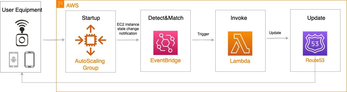
Reference architecture
The following diagram illustrates the load-balancing component of the solution, where EC2 instances in an AWS Wavelength zone are assigned Carrier IP addresses. A weighted DNS record for a host (e.g., www.example.com) is updated with Carrier IP addresses.
When a device makes a DNS query, it will be returned to one of the Carrier IP addresses associated with the given domain name. With a large number of devices, we expect a fair distribution of load across all EC2 instances in the resource pool. Given the highly ephemeral mobile edge environments, it’s likely that Carrier IPs could frequently be allocated to accommodate a workload and released shortly thereafter. However, this unpredictable behavior could yield stale DNS records, resulting in a “blackhole” – routes to endpoints that no longer exist.
Time-To-Live (TTL) is a DNS attribute that specifies the amount of time, in seconds, that you want DNS recursive resolvers to cache information about this record.
In our example, we should set to 30 seconds to force DNS resolvers to retrieve the latest records from the authoritative nameservers and minimize stale DNS responses. However, a lower TTL has a direct impact on cost, as a result of increased number of calls from recursive resolvers to Route53 to constantly retrieve the latest records.
The core components of the solution are as follows:
AWS Auto Scaling Group– a collection of EC2 instances logically grouped together for the purpose of automatic scaling.
Alongside the services above in the AWS Wavelength Zone, the following services are also leveraged in the AWS Region:
AWS Lambda – a serverless event-driven function that makes API calls to the Route 53 service to update DNS records.
Amazon EventBridge– a serverless event bus that reacts to EC2 instance lifecycle events and invokes the Lambda function to make DNS updates.
Route 53– cloud DNS service with a domain record pointing to AWS Wavelength-hosted resources.
In this post, we intentionally leave the specific load balancing software solution up to the customer. Customers can leverage various popular load balancers available on the AWS Marketplace, such as HAProxy and NGINX. To focus our solution on the auto-registration of DNS records to create functional load balancing, this solution is designed to support stateless workloads only. To support stateful workloads, sticky sessions – a process in which routes requests to the same target in a target group – must be configured by the underlying load balancer solution and are outside of the scope of what DNS can provide natively.
Automation overview
Using the aforementioned components, we can implement the following workflow automation:
Amazon CloudWatchalarm can trigger the Auto Scaling group Scale out or Scale in event by adding or removing EC2 instances. Eventbridge will detect the EC2 instance state change event and invoke the Lambda function. This function will update the DNS record in Route53 by either adding (scale out) or deleting (scale in) a weighted A record associated with the EC2 instance changing state.
Configuration of the automatic auto scaling policy is out of the scope of this post. There are many auto scaling triggers that you can consider using, based on predefined and custom metrics such as memory utilization. For the demo purposes, we will be leveraging manual auto scaling.
Amazon Virtual Private Cloud (Amazon VPC), subnets, Carrier Gateway, and Route Tables are foundational building blocks for AWS-based networking infrastructure. In our deployment, we are creating a new VPC, one subnet in an AWS Wavelength zone of your choice, a Carrier Gateway, and updating the route table for this subnet to point the default route to the Carrier Gateway.
Deployment prerequisites
The following are prerequisites to deploy the described solution in your account:
Access to an AWS Wavelength zone. If your account is not allow-listed to use AWS Wavelength zones, then opt-in to AWS Wavelength zones here.
Public DNS Hosted Zone hosted in Route 53. You must have access to a registered public domain to deploy this solution. The zone for this domain should be hosted in the same account where you plan to deploy AWS Wavelength workloads. If you don’t have a public domain, then you can register a new one. Note that there will be a service charge for the domain registration.
Amazon S3 bucket. For the Lambda function that updates DNS records in Route 53, store the source code as a .zip file in an Amazon S3 bucket.
Amazon EC2 Key pair. You can use an existing Key pair for the deployment. If you don’t have a KeyPair in the region where you plan to deploy this solution, then create one by following these instructions.
4G or 5G-connected device. Although the infrastructure can be deployed independent of the underlying connected devices, testing the connectivity will require a mobile device on one of the Wavelength partner’s networks. View the complete list of Telecommunications providers and Wavelength Zone locations to learn more.
Conclusion
In this post, we demonstrated how to implement DNS-based load balancing for workloads running in an AWS Wavelength zone. We deployed the solution that used the EventBridge Rule and the Lambda function to update DNS records hosted by Route53. If you want to learn more about AWS Wavelength, subscribe to AWS Compute Blog channel here.
A critical code-execution vulnerability in Microsoft Windows was patched in September. It seems that researchers just realized how serious it was (and is):
Like EternalBlue, CVE-2022-37958, as the latest vulnerability is tracked, allows attackers to execute malicious code with no authentication required. Also, like EternalBlue, it’s wormable, meaning that a single exploit can trigger a chain reaction of self-replicating follow-on exploits on other vulnerable systems. The wormability of EternalBlue allowed WannaCry and several other attacks to spread across the world in a matter of minutes with no user interaction required.
But unlike EternalBlue, which could be exploited when using only the SMB, or server message block, a protocol for file and printer sharing and similar network activities, this latest vulnerability is present in a much broader range of network protocols, giving attackers more flexibility than they had when exploiting the older vulnerability.
[…]
Microsoft fixed CVE-2022-37958 in September during its monthly Patch Tuesday rollout of security fixes. At the time, however, Microsoft researchers believed the vulnerability allowed only the disclosure of potentially sensitive information. As such, Microsoft gave the vulnerability a designation of “important.” In the routine course of analyzing vulnerabilities after they’re patched, Palmiotti discovered it allowed for remote code execution in much the way EternalBlue did. Last week, Microsoft revised the designation to critical and gave it a severity rating of 8.1, the same given to EternalBlue.
“You still have a lot of soldiers bringing cellphones to the frontline who want to talk to their families and they are either being intercepted as they go through a Ukrainian telecommunications provider or intercepted over the air,” said Alperovitch. “That doesn’t pose too much difficulty for the Ukrainian security services.”
[…]
“Security has always been a mess, both in the army and among defence officials,” the source said. “For example, in 2013 they tried to get all the staff at the ministry of defence to replace our iPhones with Russian-made Yoto smartphones.
“But everyone just kept using the iPhone as a second mobile because it was much better. We would just keep the iPhone in the car’s glove compartment for when we got back from work. In the end, the ministry gave up and stopped caring. If the top doesn’t take security very seriously, how can you expect any discipline in the regular army?”
This isn’t a new problem and it isn’t a Russian problem. Here’s a more general article on the problem from 2020.
Mandiant is reporting on a trojaned Windows installer that targets Ukrainian users. The installer was left on various torrent sites, presumably ensnaring people downloading pirated copies of the operating system:
Mandiant uncovered a socially engineered supply chain operation focused on Ukrainian government entities that leveraged trojanized ISO files masquerading as legitimate Windows 10 Operating System installers. The trojanized ISOs were hosted on Ukrainian- and Russian-language torrent file sharing sites. Upon installation of the compromised software, the malware gathers information on the compromised system and exfiltrates it. At a subset of victims, additional tools are deployed to enable further intelligence gathering. In some instances, we discovered additional payloads that were likely deployed following initial reconnaissance including the STOWAWAY, BEACON, and SPAREPART backdoors.
One obvious solution would be for Microsoft to give the Ukrainians Windows licenses, so they don’t have to get their software from sketchy torrent sites.
The Ukrainian army has released an instructional video explaining how Russian soldiers should surrender to a drone:
“Seeing the drone in the field of view, make eye contact with it,” the video instructs. Soldiers should then raise their arms and signal they’re ready to follow.
After that the drone will move up and down a few meters, before heading off at walking pace in the direction of the nearest representatives of Ukraine’s army, it says.
The video also warns that the drone’s battery may run low, in which case it will head back to base and the soldiers should stay put and await a fresh one.
That one, too, should be met with eye contact and arms raised, it says.
How do you prevent the most common merge conflicts when your team is working on a Serverless application? How do you make sure that your team stays productive and avoids large merge issues while trying to update the same crucial files simultaneously? –The answer to both questions is code organization! You can use cfn-include and swagger-cli to organize, collaborate, and maintain a large serverless application as well as support a large or decentralized development team.
Real life inspiration
WRAP Technologies Inc. (WRAP) creates advanced technologies for the protection and security of public safety. Their WRAP Reality product allows law enforcement agencies to train their officers using virtual reality-based scenarios.
Too many cooks in the kitchen
When multiple developers collaborate on a serverless architecture built with AWS CloudFormation, and its extensions such as the AWS Serverless Application Model (SAM), the nature of specifying resources in both the template.yaml and the optional OpenAPI.yaml specification for Amazon API Gateway leads to merge conflicts, such as the one demonstrated in the following figure where two developers are adding different API endpoints at the same time. These conflicts detract from the developer’s time and agility. Furthermore, navigating and maintaining the long template files required for a larger serverless architecture slows development as the developer scans large files to find a particular resource definition.
Figure 1. The frustrating merge conflicts.
By refactoring and organizing the CloudFormation and OpenAPI files, your development team can realize several benefits:
Improve developer efficiency by decomposing large, hard-to-manage files into a series of well-organized and single-purpose files.
Enhance developer productivity by allowing each developer to have ownership of their own code, thereby reducing the need to coordinate merges with teammates.
Eliminate potential merge issues for files that generate the most conflicts during the development of a typical Serverless API application.
Rapid development
WRAP partnered with AWS to develop and host the backend for their new officer training management platform. This entirely new platform was developed, completed, and available for use in a matter of months. Moreover, it’s a collaboration of developers spread across multiple teams worldwide, all contributing to the same code base. By instituting the norms and techniques of this post, WRAP created a large and maintainable serverless application with minimal developer code collisions.
Development of the WRAP Reality training management system was accomplished using CloudFormation for defining Infrastructure as Code (IaC), and an Amazon API Gateway OpenAPI specification for defining API contracts. The development team for the WRAP Reality training management service leveraged agile development for expediency, including the GitHub Flow branching strategy. However, since project contributors were not co-located, several considerations were put in place to make sure of consistency and speed of code development:
The API specifications and contracts were defined in OpenAPI (Swagger) specifications early in the development process, clearly defining the project structure up front, and allowing developers to independently build infrastructure components.
The two code assets central to the entire project – the CloudFormation template and the OpenAPI Specification – were decomposed into small, easily manageable components. This enabled components to be organized in a way that enhanced development productivity and practically eliminated the inevitable merge conflicts that come with large source code files that are being modified on a daily basis.
The development process was accelerated by utilizing OpenAPI integrations with AWS Services, as well as techniques for managing the OpenAPI specification and Cloudformation Template files.
Sample project
To demonstrate these techniques, we’ll explore the following sample project comprised of API endpoints for “widget” management, available on GitHub. This project provides the following end points:
/widget PUT: Creation of a new widget
/widget GET: Retrieval of a new widget
/reports/color GET: Retrieval of a set of widgets based on the widget color
/reports/filterpage GET: Retrieval of widgets based on specified filters
The overall architecture of the application is shown in the following diagram:
Figure 2. Architecture Diagram
The application comprises:
Amazon API Gateway is a fully-managed service that makes it easy for developers to create, publish, maintain, monitor, and secure APIs at any scale. In this example, API Gateway serves as the web service for the API endpoints. The mapping of data to and from the API endpoints to the Lambda functions is formally defined by an OpenAPI specification file.
AWS Lambda is a serverless compute service that lets you run code without provisioning or managing servers, creating workload-aware cluster scaling logic, maintaining event integrations, or managing runtimes. In this example, four Lambda functions are used to service each of the four API calls.
Amazon DynamoDB is a key-value and document database that delivers single-digit millisecond performance at any scale. DynamoDB is used as a persistent data store for widgets and associated properties.
OpenAPI and AWS service integration
When using API Gateway, developers have the option of using proxy Lambda integrations, or formally defining the API interface in an OpenAPI yaml file. The OpenAPI specification can be leveraged to document the API prior to development, and the example/mock features of the OpenAPI specification facilitates concurrent development by quickly establishing a working infrastructure to build upon. Furthermore, API documentation can be automatically generated from the OpenAPI specification.
As the number of endpoints increases, the OpenAPI specification file can grow in size, reaching thousands of lines of code that must be updated and maintained regularly by multiple developers. To aid in management and usability, the OpenAPI file can be decomposed into separate files for endpoints, responses, fields, and schemas.
Start with a “skeleton” file as an entry point for the OpenAPI definition, and then add a separate file for the definition of each endpoint or construct. For example, the sample project entry point is api/apiSkeleton.yaml, which contains the global definitions and effectively defines a simple list of endpoints and the reference ($ref) file path to each endpoint’s definition.
Diving into a file referenced by an endpoint, we see that it contains all of the specification details for that endpoint. Looking at the reportsColor.yaml file reveals the full endpoint specification for /reports/color:
get:
  description: Get widgets by color
  parameters:
    - in: path
      $ref: '../../requestParameters/color.yaml'
  responses:
    200:
      description: Get All the Widgets of a color
      content:
        application/json:
          schema:
            $ref: '../../schemas/widgetList.yaml'
    . . .
In turn, this endpoint specification can include further references to yaml files defining common parameters, schemas, and even full gateway responses. For example, color.yaml defines the color path variable:
  type: string
    description: "The widget's color"
    example: "Red"
To paraphrase a common catch phrase, “With a great many files, comes a great responsibility for organization.” To this end, we offer the following organizational structure as a start. Place all of the related API specifications in an “api” subfolder of your project. Have child subfolders for field, metadata, and gateway response definition files. Then, create child subfolder trees for each branch of your endpoints that mirror the endpoint paths. This will result in a highly-organized directory structure, as seen in the sample project:
We still need a consolidated single OpenAPI file to provide to CloudFormation during deployment to AWS. Therefore, the multiple files are combined and validated using the swagger-cli bundle command, resulting in a single file for deployment. The bundle command must be executed before a CloudFormation build. This command can also be included as a shortcut in the Makefile as the “buildOpenApi” command:
Once compiled, api/api.yaml is then used normally for API Gateway integrations and as a Postman API Collection import. As api/api.yaml is dynamically compiled, it’s included in .gitignore and not checked in to AWS CodeCommit.
cfn-include and nested stacks
The CloudFormation template that defines the infrastructure for even a simple service can grow to considerable length, perhaps thousands of lines. This presents challenges from a support and continued development perspective, as specific code locations become difficult to find and merge conflicts become commonplace.
CloudFormation Nested Stacks are a method of breaking a large CloudFormation template into separate templates. When there are clear delineations between groups of resources in a stack breaking it into separate nested stacks makes sense. There is also a 500 resource limit in a single CloudFormation stack and in order to go above that nested or separate stacks are necessary. Depending on the complexity of the architecture and frequency of updates however, the Nested Stacks can also become large. Furthermore, in a serverless architecture, the logical separation of architecture layers into separate stacks may not be direct, for example when a Lambda function is triggered by an event sent to an EventBridge event bus, then that Lambda function sends a different event back to the same event bus.
In these cases, CloudFormation templates can be decomposed to further leverage cfn-include . With this technique, the top-level CloudFormation template becomes a skeleton file which contains the stack parameters, global specifications, a list of resource names without properties, and the outputs. The properties of each resource are contained in separate files, referenced by an ‘include’ directive. CloudFormation template organization
To organize your CloudFormation template, deconstruct the template into one-file-per-resource, with one main “skeleton” file as the main entry point. This skeleton file contains the full parameters, global section, conditions, and output specification. The resources are specified by resource name in this skeleton file, and then an ‘include’ directive points to the file that contains the body of the resource declaration. See the following example of the main skeleton file with two resources:
This approach has the benefit of breaking the CloudFormation template into multiple small files, while still maintaining a top-level holistic view. The resource definitions, which normally comprise the majority of the content and can cause merge conflicts, are moved out of the main template.
For organization, you can create a directory in your project to contain the CloudFormation scripts. This directory also contains the entry-point skeleton file. Create further sub-folders for resources, and then further folders by resource type and architecture. We found that placing applicable AWS Identity and Access Management (IAM) role resource definitions in the same folder with the applied resource facilitated easier navigation. For example:
The files must be reconstituted to a single template.yaml for CloudFormation build and deployment. This is accomplished with the cfn-include command. A convenience command can optionally be included in the Makefile.
As the final template.yaml file is dynamically compiled, it’s included in .gitignore and not checked in to CodeCommit.
Conclusion
This post demonstrates techniques used by WRAP and AWS to rapidly develop and maintain key files in an Serverless architecture. The techniques discussed in this post allowed the WRAP and AWS team to do the following:
Improve developer efficiency by decomposing large, hard-to-manage files into a series of well-organized and single purpose files.
Enhance developer productivity by allowing each developer to have ownership of their own piece of the code without having to coordinate with teammates.
Eliminate potential merge issues on the files that typically generate the most conflicts during the development of a typical Serverless API application.
Applying these techniques was one of the key factors in the rapid development of the WRAP Reality training framework.
About the Authors:
The collective thoughts of the interwebz
Manage Consent
To provide the best experiences, we use technologies like cookies to store and/or access device information. Consenting to these technologies will allow us to process data such as browsing behavior or unique IDs on this site. Not consenting or withdrawing consent, may adversely affect certain features and functions.
Functional
Always active
The technical storage or access is strictly necessary for the legitimate purpose of enabling the use of a specific service explicitly requested by the subscriber or user, or for the sole purpose of carrying out the transmission of a communication over an electronic communications network.
Preferences
The technical storage or access is necessary for the legitimate purpose of storing preferences that are not requested by the subscriber or user.
Statistics
The technical storage or access that is used exclusively for statistical purposes.The technical storage or access that is used exclusively for anonymous statistical purposes. Without a subpoena, voluntary compliance on the part of your Internet Service Provider, or additional records from a third party, information stored or retrieved for this purpose alone cannot usually be used to identify you.
Marketing
The technical storage or access is required to create user profiles to send advertising, or to track the user on a website or across several websites for similar marketing purposes.